Capital Prospect WDGSMT2 Remote Transmitter User Manual
Capital Prospect Ltd Remote Transmitter Users Manual
User Manual
GS-MT2 Series
INSTALLATION INSTRUCTIONS
Wireless Garage Door Sensor
Model : GS-MT2
Congratulations on your purchase of the
Skylink Wireless Garage Door Sensor model
GS-MT2. The sensor is designed to monitor the
status of your garage door and work with the
Skylink M series Receiver. You will find the
installation to be simple and be able to get the
system up and running with little effort.
ONE YEAR WARRANTY
This product is guaranteed to be free of defects
in materials and workmanship for 1 year from
the date of purchase. If this product is defective,
call 1-800-304-1187 for repair or replacement
parts. Guarantee does not include normal wear
and tear or batteries.
If you have any questions, problems or missing
parts, please call Skylink Customer Support:
9:00am – 5:00pm EST, Monday-Friday.
1-800-304-1187
Or e-mail us at support@skylinkhome.com
www.skylinkhome.com
P/N:101Yxxx Rev0
SAFETY INFORMATION
This device complies with Part 15 of the FCC Rules.
Operation is subject to the following two conditions: (1)
This device may not cause harmful interference, and (2)
This device must accept any interference received,
including interference that may cause undesired
operation.
WARNING:
Changes or modifications to this unit not expressly
approved by the party responsible for compliance
could void the user’s authority to operate the
equipment.
This device complies with Industry Canada
license-exempt RSS standard(s). Operation is subject to
the following two conditions: (1) this device may not
cause interference, and (2) this device must accept any
interference, including interference that may cause
undesired operation of the device.
Cet appareil est conforme aux CNR exempts de licence
d'Industrie Canada. Le fonctionnement est soumis aux
deux conditions suivantes:
(1) Cet dispositif ne peut causer des interférences; et
(2) Cet appareil doit accepter toute interférence, y
compris les interférences qui peuvent causer un
mauvais fonctionnement de l'appareil.
CE
Declaration of Conformity
This equipment complies with the requirements
relating to electromagnetic compatibility, EN 301489-1,
EN301489-3, EN300220-1, EN300220-2 and EN60950-1.
This equipment conforms to the essential requirement
of the 1999/5/EC R&TTE Directive.
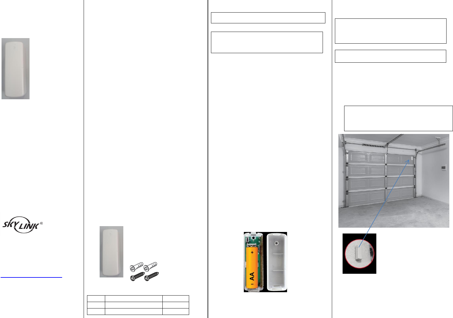
Package Contents
Parts
Description
Quantity
A
Garage Door Sensor
1
B
Mounting Accessories
1
Section 1- Programming the Sensor
Note: Battery for the sensor is not included.
Note: Each zone can program up to 4 sensors.
If you try to program a fifth sensor into a zone,
the first programmed sensor will be erased.
The sensor must be programmed to the Control
Panel before they can communication. You may
program the sensor to one of the 4 zones in the
Control Panel. Follow the steps below to program
a sensor to a specific zone;
1. Insert one AA type battery (optional) to the
Sensor based on the polarity specified in the
Sensor.
2. Refer the details of the user’s instructions to
power up the Control Panel.
3. Press and hold the Learn Button on the
Control Panel for 5 seconds until the zone 1
red LED stays on. You may release the Learn
Button.
4. If you would like to program the sensor to
zone 1, activate the sensor while the zone 1
red LED is flashing. Tilt the sensor from
vertical to horizontal to activate it.
5. If you would like to program the sensor to
other zones, press the Learn Button again,
until the red LED flashes at the zone you want
to program the sensor to, then activate the
sensor.
6. Once the sensor is programmed, the
corresponding zone red LED will be off.
Section 2 – Installation of the
Sensor
WARNING : Unplug the power cord of
your garage door opener before
installation to ensure power is not
connected.
Note: Ensure the mounting surface is smooth
and clean.
1. Mount the sensor near the top panel of your
garage door or the appropriate location by
either double sided tape or screws.
Note: Screw the mounting plate to the
frame or the panel of the garage door if
the mounting surface is not flat enough.
Then apply the double sided tape.
GS-MT2 Series
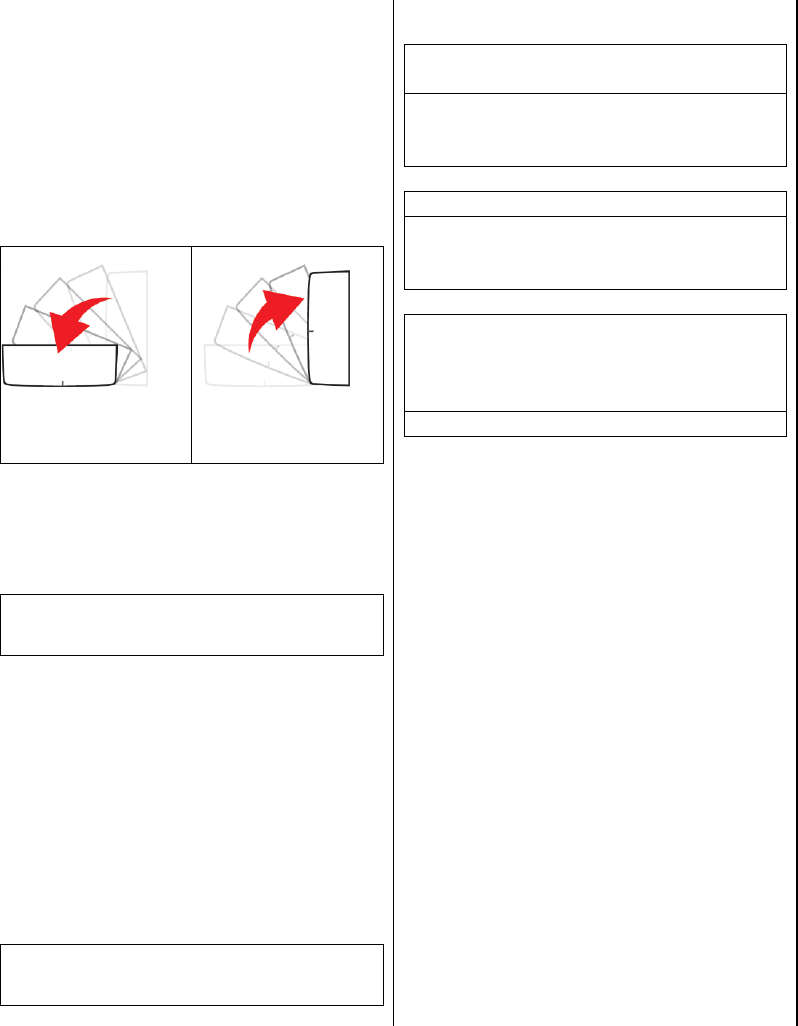
Section 3- Operation of the Sensor
The sensor is used to monitor the status of your
garage door. Once detect the door is open, the
sensor will transmit signal to the Control Panel to
notify the user.
1. The sensor will transmit the signal to the
Control Panel when detect the door is open,
the Control Panel will beep / alarm and the
corresponding zone LED will flash.
The garage door is
opening
The garage door is
closing
Section 4- Sensor Failure / Low
Battery Indication
Note: The corresponding zone LED in the
Control Panel will flash if the sensor failure or
low battery is occurred.
When the sensor failure occurs, try the following:
1. Check if the sensor is located at where it
should be.
2. Check if there is any physical damage to the
sensor.
3. Move the Control Panel closer to the sensor, if
the red LED stops flashing, that means the
Control Panel or sensor needs to be relocated.
4. Replace the battery of the sensor if the
Control Panel does not respond when the
sensor is activated within short range.
Note: Risk of explosion if battery is replaced by
an incorrect type. Dispose used batteries
according to local authority.
Section 5- FAQ
Q: The control panel does not respond to
the sensor.
A: You must program the sensor to the
control panel before they can work
together.
Q: Can I erase just one sensor from a zone?
A: You must erase all the sensors in that
zone and then program the sensor you want
to keep.
Q: I have multiple sensors in a zone and the
zone LED keep flashing that is a sensor
failure or low battery, how do I know which
sensor is having the problem?
A: You need to test each sensor individually.
WD-MT2 Series
INSTALLATION INSTRUCTIONS
Wireless Door/Window Sensor
Model : WD-MT2
Congratulations on your purchase of the
Skylink Wireless Door/Window Sensor model
WD-MT2. The sensor is designed to monitor the
status of your windows or door and work with
the Skylink M series Receiver. You will find the
installation to be simple and be able to get the
system up and running with little effort.
ONE YEAR WARRANTY
This product is guaranteed to be free of defects
in materials and workmanship for 1 year from
the date of purchase. If this product is defective,
call 1-800-304-1187 for repair or replacement
parts. Guarantee does not include normal wear
and tear or batteries.
If you have any questions, problems or missing
parts, please call Skylink Customer Support:
9:00am – 5:00pm EST, Monday-Friday.
1-800-304-1187
Or e-mail us at support@skylinkhome.com
www.skylinkhome.com
P/N:101Yxxx Rev0
SAFETY INFORMATION
This device complies with Part 15 of the FCC Rules.
Operation is subject to the following two conditions: (1)
This device may not cause harmful interference, and (2)
This device must accept any interference received,
including interference that may cause undesired
operation.
WARNING:
Changes or modifications to this unit not expressly
approved by the party responsible for compliance
could void the user’s authority to operate the
equipment.
This device complies with Industry Canada
license-exempt RSS standard(s). Operation is subject to
the following two conditions: (1) this device may not
cause interference, and (2) this device must accept any
interference, including interference that may cause
undesired operation of the device.
Cet appareil est conforme aux CNR exempts de licence
d'Industrie Canada. Le fonctionnement est soumis aux
deux conditions suivantes:
(1) Cet dispositif ne peut causer des interférences; et
(2) Cet appareil doit accepter toute interférence, y
compris les interférences qui peuvent causer un
mauvais fonctionnement de l'appareil.
CE
Declaration of Conformity
This equipment complies with the requirements
relating to electromagnetic compatibility, EN 301489-1,
EN301489-3, EN300220-1, EN300220-2 and EN60950-1.
This equipment conforms to the essential requirement
of the 1999/5/EC R&TTE Directive.
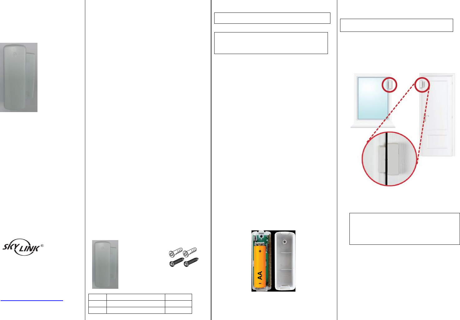
Package Contents
Parts
Description
Quantity
A
Door/Window Sensor
1
B
Mounting Accessories
1
Section 1- Programming the Sensor
Note: Battery for the sensor is not included.
Note: Each zone can program up to 4 sensors.
If you try to program a fifth sensor into a zone,
the first programmed sensor will be erased.
The sensor must be programmed to the Control
Panel before they can communication. You may
program the sensor to one of the 4 zones in the
Control Panel. Follow the steps below to program
a sensor to a specific zone;
1. Insert one AA type battery (optional) to the
Sensor based on the polarity specified in the
Sensor.
2. Refer the details of the user’s instructions to
power up the Control Panel.
3. Press and hold the Learn Button on the
Control Panel for 5 seconds until the zone 1
red LED stays on. You may release the Learn
Button.
4. If you would like to program the sensor to
zone 1, activate the sensor while the zone 1
red LED is flashing. Tilt the sensor from
vertical to horizontal to activate it.
5. If you would like to program the sensor to
other zones, press the Learn Button again,
until the red LED flashes at the zone you want
to program the sensor to, then activate the
sensor.
6. Once the sensor is programmed, the
corresponding zone red LED will be off.
Section 2 – Installation of the
Sensor
Note: Ensure the mounting surface is smooth
and clean.
1. Place the sensor in the appropriate location:
i.e. Window or Door. Mount the
Door/Window sensor on your window or door
with the provide screws or double sided tape.
Note: Screw the mounting plate to the
frame or the panel of the window or
door if the mounting surface is not flat
enough. Then apply the double sided
tape.
WD-MT2 Series
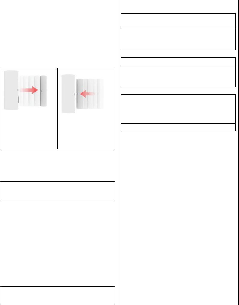
Section 3- Operation of the Sensor
The sensor is used to monitor the status of your
window or door. Once detect the window or
door is open, the sensor will transmit signal to
the Control Panel to notify the user.
1. The sensor will transmit the signal to the
Control Panel when detect the door is open,
the Control Panel will beep / alarm and the
corresponding zone LED will flash.
Activate the sensor by
separating the
magnetic contact of
the sensor.
Move the magnetic
contact back to the
sensor.
Section 4- Sensor Failure / Low
Battery Indication
Note: The corresponding zone LED in the
Control Panel will flash if the sensor failure or
low battery is occurred.
When the sensor failure occurs, try the following:
1. Check if the sensor is located at where it
should be.
2. Check if there is any physical damage to the
sensor.
3. Move the Control Panel closer to the sensor, if
the red LED stops flashing, that means the
Control Panel or sensor needs to be relocated.
4. Replace the battery of the sensor if the
Control Panel does not respond when the
sensor is activated within short range.
Note: Risk of explosion if battery is replaced by
an incorrect type. Dispose used batteries
according to local authority.
Section 5- FAQ
Q: The control panel does not respond to
the sensor.
A: You must program the sensor to the
control panel before they can work
together.
Q: Can I erase just one sensor from a zone?
A: You must erase all the sensors in that
zone and then program the sensor you want
to keep.
Q: I have multiple sensors in a zone and the
zone LED keep flashing that is a sensor
failure or low battery, how do I know which
sensor is having the problem?
A: You need to test each sensor individually.