Capricorn Electronics TM1 Wireless Tank Monitor User Manual
Capricorn Electronics Ltd Wireless Tank Monitor
User manual
TM1 Wireless Tank Monitor
Instruction Manual
Nov 2018
Description
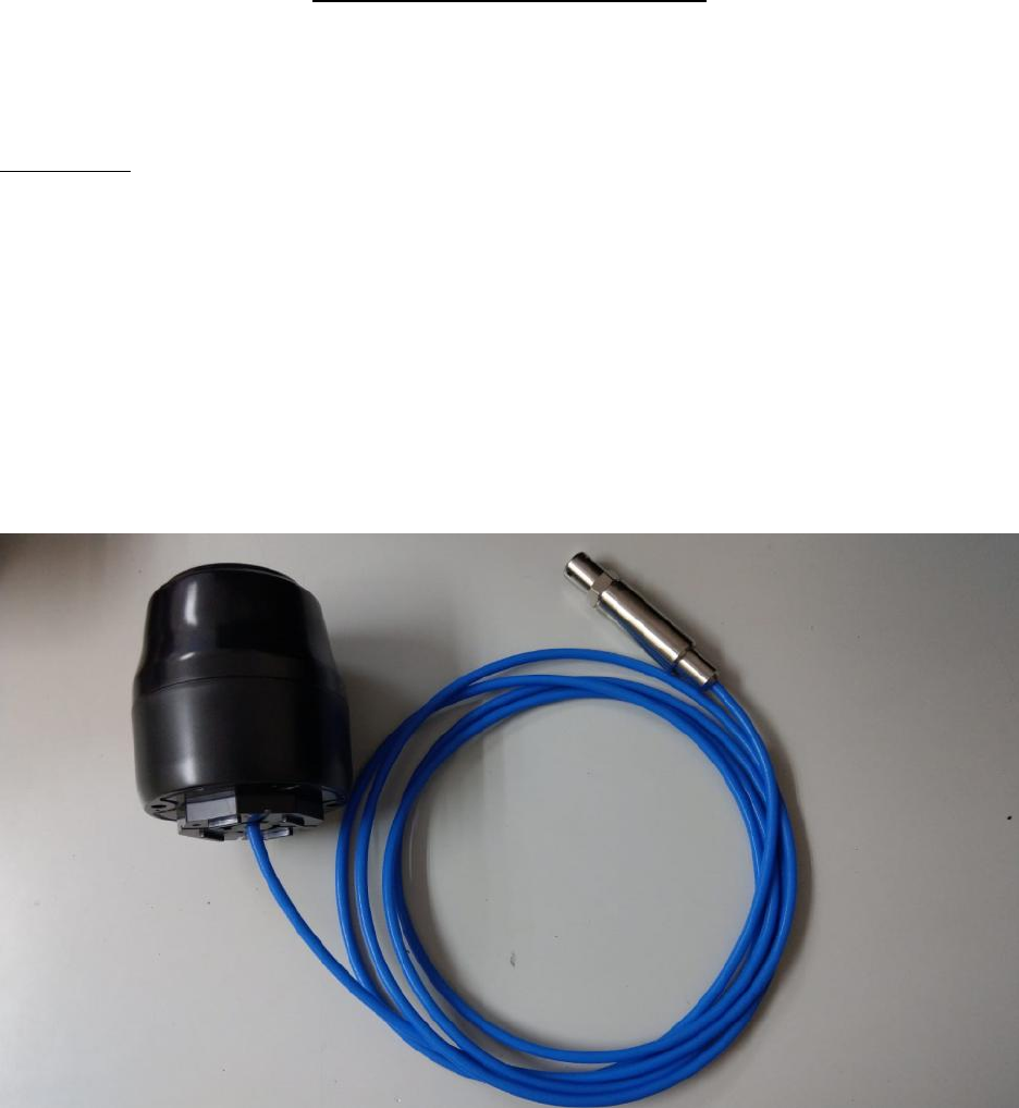
The TM1 Remote Tank level Monitor consists of a self contained battery operated
cellular transceiver fitted into an enclosure with batteries, having a submersible
pressure transducer attached, that is lowered into a tank of liquid to be monitored for
level.
The plastic enclosure has a lower threaded mounting at its base that allows it to be
fitted through a hole atop a tank, or onto an external flange.
A chemical resistant cable extends from the sensor to a lower entry point in the TM1
underbody.
A set of three “D” cells are enclosed that power the electronics and the Cellular modem.
The TM1 utilizes the LTE CAT M1 service provided by Verizon Wireless in the USA that
operates in the 750 MHz cellular 4G band.

The TM1 can be used to send a tank level report over the cellular link at repeated time
intervals and on a schedule. The number of reports can be altered by command but is
typically set to once every 4 hours.
Contact your supplier, agent or FLEET data service provider for changes to reporting
schedules and times.
The data packet it sends is only several hundred bytes in length and includes pressure
reading, battery health, temperature and signal level information.
It utilizes a CAT M1 Modem that allows transmissions over the Cellular network,
permitting short burst data transfers to conserve battery life.
Installation and Activation
The TM1 must always be mounted upright, in the open, clear of any metallic shields or
obstructions and within the propagation footprint of a Verizon LTE cell tower.
Drill a mounting hole that is 1.75” ( 45 mm) Diameter at the top of the tank such that it is
at the highest point or above the maximum liquid level.
NOTE: The TM1 has slots at its mounting flange that will allow liquid to drain to the
outside of the tank if the liquid level is above the lowest point on the TM1 body. This is
to stop any liquid forcing its way past the gasket and into the TM1 body. If the filling port
is above this level, fit an extension tube or fitting to the tank so that it holds the TM1
above the refilling port level.
Lower the transducer into the tank and as it feeds through the hole feed it through the
tightening nut provided.
Allow the transducer to lay horizontally flat at the lowest part of the tank.
Tighten the mounting nut onto the TM1 mounting flange.
Once the TM1 is in place, remove the small magnetic keeper from the side of the TM1
body. This will initiate the transmission and registration with the FLEET server and
should bring up a reading on the device page or dashboard on FLEET.
The Magnet can be used at any time to disable the TM1 for transporting or trouble
shooting. To reboot the TM1 insert the magnetic keeper with the engagement slot facing
downwards. Hold it there for about 15 seconds and then remove it.
Save the magnet for future use.

Servicing the TM1
From time to time, depending on the reporting frequency, local cell tower signal strength
and climatic conditions, the three “D” cell batteries will require replacement.
(i) If the TM1 is in a Hazardous location, remove it to a safe location first.
(ii) Then insert the magnetic Keeper.
(iii) Remove the four screws holding the base and the upper cover using a Philips
screwdriver.
(iv) With the top cover removed, observe the location of the batteries and the way
they are held in place.
(v) Cut away any zip ties allowing the batteries to be carefully removed.
OBSERVE the battery polarity. Two on one side have POSITIVE facing UP and
the single battery on the opposite side of the board should have the Negative
facing DOWN.
(vi) Replace the three “D” cells with top quality long life batteries such as
Duracell “Quantum” or Energizer “Ultimate”.
Select ones having at least 5 years shelf life.
Do NOT use rechargeable batteries.
Do NOT use old batteries.
Do NOT mix battery types or old ones with new.
(vii) Make sure polarity is correct and use two zip ties thro holes in PCB provided to
hold the three cells in place. Make sure the ties are clear of other components
when tightened. Cut off any excess zip tie.
(viii) With the two-battery set facing you, carefully refit the top cover with the magnetic
keeper to your left. Screw the 4 screws tightly ensuring proper engagement of
the top and the base.
(ix) Make sure the magnetic keeper is installed correctly for 15 secs before removing
for activation.
DO NOT TAMPER or ATTEMPT ANY REPAIRS YOURSELF.
Always contact your supplier for service, repairs or changing device factory settings.
FCC Compliance
Section 15.21 Information to user
Changes or modifications not expressly approved by the party responsible for
compliance could void the user's authority to operate the equipment
Section 15.19 Labeling requirements:
This device complies with Part 15 of the FCC Rules. Operation is subject to the
following two conditions:
(1) this device may not cause harmful interference, and
(2) this device must accept any interference received, including interference that may
cause undesired operation.
Section 15.105 (b)
Note: This equipment has been tested and found to comply with the limits for a Class B
digital device, pursuant to part 15 of the FCC Rules. These limits are designed to
provide reasonable protection against harmful interference in a residential installation.
This equipment generates, uses and can radiate radio frequency energy and, if not
installed and used in accordance with the instructions, may cause harmful interference
to radio communications. However, there is no guarantee that interference will not occur
in a particular installation. If this equipment does cause harmful interference to radio or
television reception, which can be determined by turning the equipment off and on, the
user is encouraged to try to correct the interference by one or more of the following
measures:
--Reorient or relocate the receiving antenna.
--Increase the separation between the equipment and receiver.
--Connect the equipment into an outlet on a circuit different from that to which the
receiver is connected.
--Consult the dealer or an experienced radio/TV technician for help.
IMPORTANT NOTE:
To comply with FCC RF exposure compliance requirements, the antenna used for this
transmitter must be installed to provide a separation distance of at least 20 cm from all
persons and must not be co-located or operating in conjunction with any other antenna
or transmitter”
ooOoo