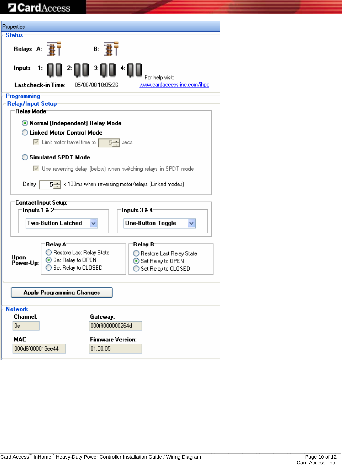
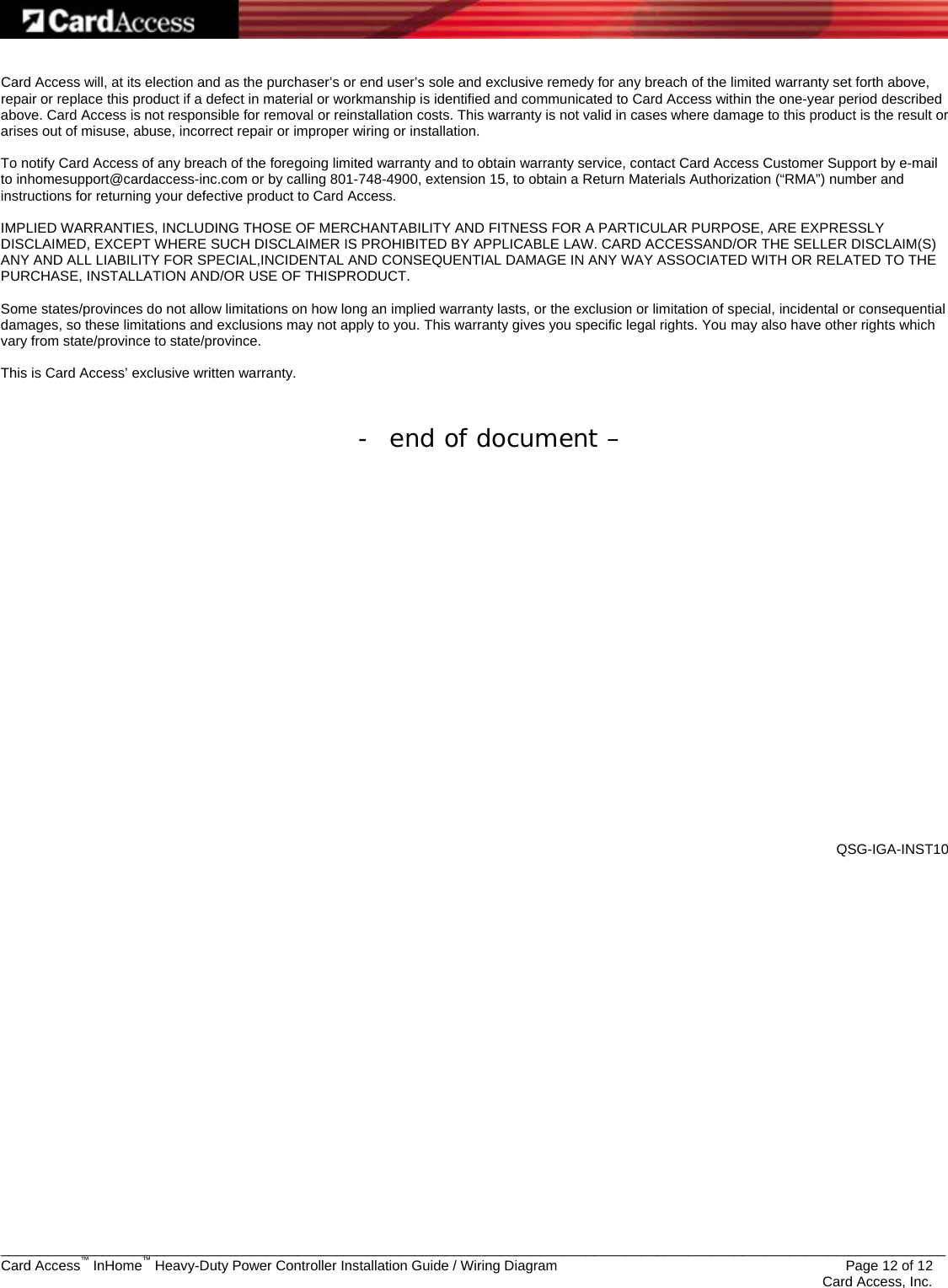
Card Access HPC10 Heavy-Duty Power Controller User Manual Exhibit 8

Card Access Inc Heavy-Duty Power Controller Exhibit 8

Exhibit 8

  _________________________________________________________________________________________________________________________ Card Access™ InHome™ Heavy-Duty Power Controller Installation Guide / Wiring Diagram                 Page 1 of 12    Card Access, Inc.    InHome™ Heavy-Duty Power Controller Model Number: HPC10A  Installation Guide / Wiring Diagram                      The information contained in this document represents current information and views of Card Access, Inc. as of the date of publication. Card Access cannot guarantee the accuracy of any information presented after the date of this document’s publication.  COPYRIGHT ©2008 Card Access, Inc. All rights reserved. Any previously copyrighted contents contained herein remain the property of the respective creators.  Card Access, InHome, Wires Not Included, and The Wire Stops Here are trademarks of Card Access, Inc. Control4 is a registered trademark and 4Sight is a trademark of Control4 Inc. ZigBee is a trademark of the ZigBee Alliance. GE is a trademark of General Electric Company. CEDIA is a trademark of the Custom Electronic Design & Installation Association. Other marks may be the property of their respective owners.
  _________________________________________________________________________________________________________________________ Card Access™ InHome™ Heavy-Duty Power Controller Installation Guide / Wiring Diagram                 Page 2 of 12    Card Access, Inc. Card Access InHome™ Heavy-Duty Power Controller Installation Guide Enable Automation Events for High-Voltage Systems in the Control4® Automated Home  Introduction The Card Access™ InHome™ Heavy-Duty Power Controller (HPC10A) is a wirelessly controlled power controller specifically designed for use with the Control4® home automation system and is Control4 Certified.  This gives the Control4-automated homeowners the ability to turn high-voltage items on or off based on the time of day, and even operate them from a remote location with Control4’s 4Sight™ service.  The InHome Heavy-Duty Power Controller can also be operated independent of the home automation system by ‘hard-wiring’ in switches and controls in Stand-Alone configuration.  The device consists of two high voltage 100-240VAC 30 Amp relays that can be independently configured to control the following types of loads:  • motors • resistive loads •  ballast type loads  in residential or commercial applications.  The control and configuration of these relays can occur through the Control4 Composer application (Control4 Operating Mode), or directly on the device, (Stand-Alone Operating Mode).  Control4 Operating Mode: To operate in Control4 mode the device must be identified into the project. This is done by tapping of the ID button (the method common to other devices in Control4 projects.)  Once the device is identified, its four contact inputs and two independently controlled high-voltage relays are available to the project for configuration and control.  Device control is accomplished through one of three methods:  •  Through an IEEE 802.15.4 ZigBee-based wireless radio signal •  Through the four local switch inputs •  Through a combination of both methods  Using both methods provides for failsafe independent operation.  The InHome Heavy-Duty Power Controller’s Control4 driver supports complete device configuration and operation through user selectable options.  The device utilizes Control4’s proxies for control of blind motors, lifts, screens, gate motors, fountain and pool pump motors, lighting loads, and appliance loads, etc.  The device also includes several easy-to-use diagnostic modes to help installers set the device up for proper operation.  Stand-Alone Operating Mode: In Stand-Alone Operating Mode, the device uses the four dry contact closure inputs to control the two high-voltage power relays in a one (1), two (2), or 3 button control configuration.  This allows for a wide variation of configurations and homeowner operation.  The InHome Heavy-Duty Power Controller’s onboard switches enable ease of setup, easy diagnostic test, and easy troubleshooting for installers.  LEDs indicate relay status and radio functionality.   A relay disable switch is provided to allow functional test by the installer without sending power to connected high-power devices, allowing easy testing of the system.  The InHome Heavy-Duty Power Controller is powered by one of two methods:
  _________________________________________________________________________________________________________________________ Card Access™ InHome™ Heavy-Duty Power Controller Installation Guide / Wiring Diagram                 Page 3 of 12    Card Access, Inc. 1.  Connecting a 100-240VAC line power to the High Voltage terminals of the device 2.  Connecting a 12VDC power supply to the power inputs of the Low Voltage terminal connector   No power jumpers or setting are required just connect one or the other (line power or external DC power supply in).    The device is designed to be permanently mounted in a fixed location.  Power cables can be connected to the device using conduit or by connecting flexible power lines to the device with feed through cable clamps.  Figure 1 below shows you where the InHome Heavy-Duty Power Controller is placed in a typical installation.     GRAPHIC TBD – show fixed mounting by conduit and by cable clamp   Figure 1 – InHome Heavy-Duty Power Controller in a Typical Installation  Specifications Specifications for the InHome Heavy-Duty Power Controller are as follows:   HPC10A Specifications   Dimensions  4.6” x 10.5” x 2.1” Weight  3.5 Lbs Maximum Ambient Operational Temperature  75 C Power Input  100-240VAC at 50/60Hz,  0.1 Amps  Or 12VDC, 200mAmps Relay Contact Ratings (per relay)  Voltage  Load Type  Contact Rating 240VAC General Purpose  30 Amps 240VAC  UL Resistive  25 Amps 120VAC Motor  1 HP 240VAC Motor  2 HP 277VAC Ballast  10 Amps  HV wiring  8 – 14 Gauge wiring depending on Load* * An accessible disconnect device shall be installed into the fixed wiring.   Device must be wired by an authorized electrician in accordance with the National Electrical Code, ANSI/NFPA 70-1987.  In the European community, the unit must be wired by an authorized electrician in accordance with all applicable European codes Operational Environment  Device shall be mounted in a dry moisture protected location in accordance with National Electrical Code
  _________________________________________________________________________________________________________________________ Card Access™ InHome™ Heavy-Duty Power Controller Installation Guide / Wiring Diagram                 Page 4 of 12    Card Access, Inc.        !!! WARNING !!!: <warning verbiage here>    Control4 Compatibility    NOTE:  <note verbiage here>   Site Requirements and Wiring Options <This Section TBD – be sure that the device is placed in a safe moisture free location as specified in accordance with all local and national electrical codes.  Ensure that appropriate accessible disconnect devices (circuit breaker) are installed into the fixed wiring of the device.  Ensure that the devices cover is securely replaced after device setup and configuration.>    Low-Voltage Wiring Diagram Option   High-Voltage Wiring Diagram Options Option 1:  Used where a single external breaker to the device is used and the load is powered from this power source.
  _________________________________________________________________________________________________________________________ Card Access™ InHome™ Heavy-Duty Power Controller Installation Guide / Wiring Diagram                 Page 5 of 12    Card Access, Inc. Option 2:  Used where each load uses its own external circuit breaker  Option 3:  Used where a combination of power sources are used; load “A” is powered by an external breaker in the load path and load “B” is powered by the devices external breaker or power source.       For a Control4 Operating Mode installation of the InHome Heavy-Duty Power Controller, you must perform the following steps:   Control4 Operating Mode Installation Hardware Installation Instructions     !!! WARNING !!!: An accessible disconnect device shall be installed
  _________________________________________________________________________________________________________________________ Card Access™ InHome™ Heavy-Duty Power Controller Installation Guide / Wiring Diagram                 Page 6 of 12    Card Access, Inc.  into the fixed wiring.   Device must be wired by an authorized electrician in accordance with the National Electrical Code, ANSI/NFPA 70-1987.  In the European community, the unit must be wired by an authorized electrician in accordance with all applicable European codes.     Step One Choose an appropriate location to place the InHome Heavy-Duty Power Controller which ensures the following:  •  Device will be appropriately protected from environmental conditions •  Device can be screw mounted to a stable surface  •  Location provides easy access to any externally connected wires •  Location ensures a good wireless connection into your ZigBee mesh network if using with a Control4 system. •      NOTE:  Make sure the InHome Heavy-Duty Power Controller is positioned for good ZigBee wireless reception by (1) ensuring it is within 150 feet of another ZigBee device and (2) avoiding other electrical equipment that may cause interference with the ZigBee signal (such as cordless telephones that operate on the 2.4 GHz frequency).      NOTE:  We recommend you not place the InHome Heavy-Duty Power Controller ?????.  Step Two Thread the low voltage (Class B) external contact input control wires, and the low voltage power supply wires through the wall of the enclosure which is opposite and on the same end as the Antenna connector.  These wires can be secured to the enclosure using conduit or feed through clamps.  Secure the wiring to the terminal strip as illustrated in the Low Voltage wiring diagram  Step Three Thread the High Voltage wires through the wall of the enclosure on either side of the high voltage terminal end of the device.  These wires can be secured to the enclosure using conduit or feed through clamps.  Secure the wiring to the terminal strip using an appropriate option as illustrated in the High Voltage wiring   Step Four Insert and tighten the mounting screws.   Step Five   Step Six Select the desired operational mode by setting the dip switches located on the PCB to the appropriate position.  The operational modes are described below:   Figure 2 below shows describes the dip switch settings available to configure the electrical characteristics of InHome Heavy-Duty Power Controller when controlling specific types of target devices.  Dip Switches 1 | 2 | 3| 4  Type Input 1  Input 2  Input 3  Input 4  Default Settings OFF|OFF|OFF|OFF  Control4 Mode  Configured through Control4® Automation System  Normal (Independent Relay) Modes
  _________________________________________________________________________________________________________________________ Card Access™ InHome™ Heavy-Duty Power Controller Installation Guide / Wiring Diagram                 Page 7 of 12    Card Access, Inc. OFF|OFF|OFF|ON  2 Button, Latched  Relay A Close  Relay A Open Relay B Close  Relay B Open ON|OFF|OFF|ON 1 Button, Momentary  Press: Relay A Close Release: Relay A Open   Press: Relay B Close Release: Relay B Open  OFF|ON|OFF|ON  1 Button, Toggle  1st: Relay A Close 2nd: Relay A Open    1st: Relay B Close 2nd: Relay B Open   ON|ON|OFF|ON  1 Button: Toggle Relay A Momentary Relay B 1st: Relay A Close 2nd: Relay A Open   Press: Relay B Close Release: Relay B Open   Linked (Motor Control) Modes OFF|OFF|ON|OFF  1 Button, Toggle  1st: Relay A Close.   2nd: Both Open 3rd: Relay B Close.   4th: Both Open     ON|OFF|ON|OFF 2 Button, Momentary  Press: Relay A Close Release: Both Open   Press: Relay B Close Release: Both Open  OFF|ON|ON|OFF  2 Button, Toggle  1st: Relay A Close 2nd: Both Open    1st: Relay B Close 2nd: Both Open   ON|ON|ON|OFF  3 Button, Latched  Relay A Close  Both Open  Relay B Close   OFF|OFF|ON|ON Delay Learning Mode  1st: Relay A Close.   Release: Both Open 2nd: Relay B Close.   Release: Both Open      Linked (Simulated SPDT) Modes ON|OFF|OFF|OFF 1 Button, Momentary  Press: Relay A Close Release: Relay B Close      OFF|ON|OFF|OFF  1 Button, Toggle  1st: Relay A Close 2nd: Relay B Close      ON|ON|OFF|OFF  2 Button, Latched  Relay A Close    Relay B Close    1st = “First Press” or “First Contact Input Closure,”   2nd = “Second Press” or “Second Contact Input Closure,”   etc. Card Access and InHome are trademarks of Card Access, Inc.  Control4 is a registered trademark of Control4, Inc. STK-HPC-10  Figure 2 – InHome Heavy-Duty Power Controller Dip Switch Configuration  •  Normal (Independent Relay) Mode:  o  In Normal Mode the relays do just what you tell them to do without regard to anything else that may be involved.  They act completely independent of each other.  The 4 inputs can be wired to different types of closure devices and are set up to control the individual relays in following configurations:    Two button, Latched (Dip switch setting OFF OFF OFF ON)  Hooking up a toggle switch between inputs 1 and 2 will open and close relay A as you switch between one side or the other of the toggle switch.  Hooking a toggle switch between inputs 3 and 4 will open and close relay B.  Latched refers to the switch stays in that position until moved by the user.   1 Button, Momentary.  This allows the user to wire up a momentary pushbutton switch to control the relays as described in the table    1 Button, Toggle.  This allows the user to wire up a single switch, usually a momentary contact switch and then to toggle through the relay conditions defined in the table as the switch closure is activated.
  _________________________________________________________________________________________________________________________ Card Access™ InHome™ Heavy-Duty Power Controller Installation Guide / Wiring Diagram                 Page 8 of 12    Card Access, Inc.   1 Button: Toggle Relay A, Momentary Relay B.  This gives the user the option of having 1 relay controlled by a toggle switch and the other relay controlled by a momentary pushbutton switch  o  The reason that it is labeled Normal Mode is to indicate the individual nature of the relay operation.  The user can do whatever they want with the switch inputs and the relays will follow according to the Type of switch connected to the input.  No relay protection, relay timing or any other specialized relay operation is added  •  Linked Mode (Motor Control)  o  This mode is used for controlling motors that do not have built in motor controllers.  Many motors assemblies already have a built in motor controller that governs operation.  If your motor assembly has a built in motor controller we recommend using Normal mode to control your motor assembly.  If your application does not have a built in motor controller you can use this mode to control your motor.  In linked mode the two relays operate such that both relays cannot be activated at the same time.  This protects the motor assembly from being energized to operate in opposing directions. The relays are also governed by a “motor travel time” values which allows the motor to be turned off, after initial activation, in a preset amount of time.  Typical applications for Linked Mode – Motor Control use are: Gate open/close control, Screen up/down control, Blinds open/closed control, or other applications that require two motor direction operations without a built in motor controller.    1 button, Toggle mode.  This mode links the two relays together not allowing one relay to close while the other is closed and visa versa.  (both relays cannot be closed at the same time)  A single button can control the direction of a motor.  Press once and relay A closes – (screen comes down until the motor travel time is reached). Press again and both relays open – (screen stops). Press again and relay B closes – (screen goes up until motor travel time is reached).  Press again and screen stops.  Press again and the cycle repeats.    2 button momentary – as described in the table    3 button latched – as described in the table    Delay Learning Mode. This mode allows you to set or change the Maximum Motor Travel time limit.  The Default time limit is set to 15 seconds.  A new time limit can be stored by the user, and once stored, is then used in all future Linked (Motor Control) Mode operations.  The user sets this time by pressing and holding the Input 1 Switch for the desired time delay.  This is accomplished as follows:  Upon pressing Input 1, Relay “A” closes and the LED will turn yellow and will begin blinking at a 1 second rate (screen is going down).  When the Input 1 button is released, Relay “A” opens and the LED turns to red (screen stops) and the delay time is temporarily saved.  The time is then permanently stored in the device by pressing and holding the ID button for 4 seconds.  Holding the ID button for 4 seconds will cause the LED to flash yellow 3 times indicating that a new default time value has been permanently stored in the device.  The Maximum Motor Travel time is limited to 255 seconds.  The user can now switch to any other Linked (Motor Control) Mode dip switch setting and the newly saved time will be applied to all relay operations. The user can disable the Maximum Motor Travel time limit (setting value to zero) by pressing and holding the ID button without previously activating any relay (not pressing and holding Input Switch 1).  Pressing and holding the ID button for 4 seconds two times in a row will set the Maximum Motor Travel time limit to zero and disable all timed operations.  •  Linked (Simulated SPDT) Mode  o  This mode allows the user to link the two SPST relays together in order to simulate a single SPDT relay.  Essentially what this means is that when relay A is open relay B will always be shut and when relay B is open relay A will always be shut.  This mode will operate in SPDT mode as long as the device has power.  If power is lost the relays will default to the normally open position.      Software Installation Instructions  Step Seven Add the InHome Heavy-Duty Power Controller to your Composer project. When prompted to identify the unit, press the ID button, located on the PC board, four times. The InHome Wireless Contact Relay LED will blink the green LED twice to confirm the ID has been sent to the Control4 system. To set up the 2 relay outputs and the 4 contact inputs in the Composer project, refer to your system setup documentation.   Step Eight (Optional) Configure advanced properties.
  _________________________________________________________________________________________________________________________ Card Access™ InHome™ Heavy-Duty Power Controller Installation Guide / Wiring Diagram                 Page 9 of 12    Card Access, Inc. • The two SPST relays can optionally be linked to simulate a single SPDT relay by selecting the option box in the InHome Wireless Contact Relay’s properties page.   IMPORTANT! Unlike a true SPDT relay, both relays will open during a power failure. • If you use the InHome Heavy-Duty Power Controller’s temperature sensing capabilities, you may need to enter a temperature offset into the InHome Heavy-Duty Power Controller’s properties page in order to accommodate for variances in thermistors. (When multiple temperature sensors are located in the same room, you may notice each sensor shows a slightly different reading. This results from normal manufacturing variances in temperature sensors.) A correction can be entered so the product’s reported temperatures match those reported by other devices.  Step Nine The InHome Heavy-Duty Power Controller provides diagnostics to aid proper installation. Sliding the relay switch to the disable position to disconnect the relays from being energized.  This allows diagnostsic operational testing without engaging the power devices connected to the relays.  Once you have validated device operation do a full check by engaging the actual devices that are being controlled.  You can also check radio operation by entering Radio Test mode.  To enter test mode push and hold the ID button for one-half second. <describe radio test mode> To exit Test Mode, simply allow the Test Mode to time out (approximately five minutes)—the unit will continue to function correctly while still in Test Mode. This is the recommended procedure. You may also exit Test Mode early by removing all power sources from the unit for at least 10 seconds.    Product Support If you have any difficulties, please contact Card Access Product Support at +1.801.748.4900, extension 15 weekdays from 8am to 5pm Mountain Time for technical assistance.
  _________________________________________________________________________________________________________________________ Card Access™ InHome™ Heavy-Duty Power Controller Installation Guide / Wiring Diagram                 Page 10 of 12    Card Access, Inc.
  _________________________________________________________________________________________________________________________ Card Access™ InHome™ Heavy-Duty Power Controller Installation Guide / Wiring Diagram                 Page 11 of 12    Card Access, Inc.  Product Registration Please visit www.cardaccess-inc.com/inhome/registration to register your new product. Along with your contact information, you must provide the following additional information:  • Product Name (Card Access InHome Heavy-Duty Power Controller)  • Model Number (HPC10A)  • Date of Purchase  • Place of Purchase  • Serial Number (this is the “MAC ID” located on the sticker attached to the radio/logic board inside the Cover Assembly of either one of the InHome Wireless Contact Switches included in the Package) Please refer to the One-Year Limited Warranty for complete warranty information.  Regulatory Statements The Card Access InHome Heavy-Duty Power Controller complies with standards established by the following regulatory bodies: Federal Communications Commission (FCC), Conformité Européene (CE), and Restriction of Hazardous Substances (RoHS).  FCC ID: MHIHPC10 This device complies with Part 15 of the FCC Rules. Operation is subject to the following two conditions:  (1) this device may not cause harmful interference, and (2) this device must accept any interference received, including interference that may cause undesired operation.  This equipment has been tested and found to comply with the limits for a Class B digital device, pursuant to Part 15 of the FCC Rules. These limits are designed to provide reasonable protection against harmful interference in a residential installation. This equipment generates, uses, and can radiate radio frequency energy and, if not installed and used in accordance with the instructions, may cause harmful interference to radio communications. However, there is no guarantee that interference will not occur in a particular installation. If this equipment does cause harmful interference to radio or television reception, which can be determined by turning the equipment off and on, the user is encouraged to try to correct the interference by one or more of the following measures:  • Reorient or relocate the receiving antenna. • Increase the separation between the equipment and receiver. • Connect the equipment into an outlet on a circuit different from that to which the receiver is connected. • Consult the dealer or an experienced radio/TV technician for help.  IMPORTANT! Changes or modifications not expressly approved by Card Access, Inc. void the user’s authority to operate the equipment.  CE  We, Card Access, Inc. of 11778 South Election Road, Suite 260, Salt Lake City, Utah, 84020 USA, declare under our sole responsibility that the Card Access’ InHome Heavy-Duty Controller, Model Number HPC10A, to which this declaration relates, are in conformity with the following standards and / or other normative documents:   EN60950, EN55022, EN55024  We hereby declare that the above named product is in conformity with the essential requirements and other relevant provisions of Directive 1999/5/EC. The conformity assessment procedure referred to in Article 10(3) and detailed in Annex II of Directive 1999/5/EC has been followed.   One-Year Limited Warranty This product is warranted to be free of defects in material and workmanship for one year from date of original purchase from Card Access, Inc. (“Card Access”).
  _________________________________________________________________________________________________________________________ Card Access™ InHome™ Heavy-Duty Power Controller Installation Guide / Wiring Diagram                 Page 12 of 12    Card Access, Inc.  Card Access will, at its election and as the purchaser’s or end user’s sole and exclusive remedy for any breach of the limited warranty set forth above, repair or replace this product if a defect in material or workmanship is identified and communicated to Card Access within the one-year period described above. Card Access is not responsible for removal or reinstallation costs. This warranty is not valid in cases where damage to this product is the result or arises out of misuse, abuse, incorrect repair or improper wiring or installation.   To notify Card Access of any breach of the foregoing limited warranty and to obtain warranty service, contact Card Access Customer Support by e-mail to inhomesupport@cardaccess-inc.com or by calling 801-748-4900, extension 15, to obtain a Return Materials Authorization (“RMA”) number and instructions for returning your defective product to Card Access.  IMPLIED WARRANTIES, INCLUDING THOSE OF MERCHANTABILITY AND FITNESS FOR A PARTICULAR PURPOSE, ARE EXPRESSLY DISCLAIMED, EXCEPT WHERE SUCH DISCLAIMER IS PROHIBITED BY APPLICABLE LAW. CARD ACCESSAND/OR THE SELLER DISCLAIM(S) ANY AND ALL LIABILITY FOR SPECIAL,INCIDENTAL AND CONSEQUENTIAL DAMAGE IN ANY WAY ASSOCIATED WITH OR RELATED TO THE PURCHASE, INSTALLATION AND/OR USE OF THISPRODUCT.   Some states/provinces do not allow limitations on how long an implied warranty lasts, or the exclusion or limitation of special, incidental or consequential damages, so these limitations and exclusions may not apply to you. This warranty gives you specific legal rights. You may also have other rights which vary from state/province to state/province.  This is Card Access’ exclusive written warranty.   - end of document –               QSG-IGA-INST10

Navigation menu