Cardin Elettronica RM-S435 Automatic alarm opening system User Manual
Cardin Elettronica spa Automatic alarm opening system
User Manual

ZVL378.00 MOD:20-10-2000
L378.00 S435 20-10-2000AM
CARDIN ELETTRONICA spa
Via Raffaello, 36- 31020 San
Vendemiano Treviso (TV) Italy
Tel: +39/0438.401818
Fax: +39/0438.401831
email (Italy): Sales.office.it@cardin.it
email (Europe): Sales.office@cardin.it
Http: www.cardin.it
Warning: Changes or alterations made to this device which have not been expressly approved by the
party responsible for compliance with the local standards and regulations could cancel the user's
authority to operate the equipment.
NOTE: This equipment has been tested and found to comply with the limits for a class B digital device,
according to part 15 of the FCC rules. These limits are designed to provide reasonable protection against
harmful interference to radio communications.
However, there is no guarantee that interference will not occur in a particular installation. If this equipment
does cause harmful interference to radio or television reception, which can be determined by turning the
equipment off and on, the user is advised to try to correct the situation by taking one or more of the
following measures:
• Reorientate or relocate the receiving antenna
• Increase the distance between the equipment and the receiver
• Connect the equipment to a wall socket which is on a different ring circuit to that of the receiver
• Consult your dealer or an experienced radio/TV technician for help.
Description
The S435 radio control system consists of one or more transmitters and one or more receivers
which can be combined to meet the specific needs of the system.
The S435 system uses a highly reliable encoding system guaranteed by the use of dynamic
codes. The code is changed for each encoding transmission through the use of an encoding
algorithm which only the receiver is able to recognise and therefore decide whether or not the
code transmitted corresponds to the original code. The code is generated for each channel in
the transmitter using the random arbitrary method with 2
36
combinations. The generated code is
memorised in the receiver via radio. The receiver is able to memorise 128 different codes. During
the transfer stage the codes are memorised in a non volatile memory module which can be
moved to another receiver without having to reprogram it. As this is a system based on dynamic
codes each code is processed individually by the receiver.
Important
This is a device which uses a high security encoding system it follows therefore that if you
lose one or more transmitters you will have to reprogram the system codes. The transmit-
ted code changes for each command (rolling code). Disturbance during the transmission will
deactivate the relay, at this point the relay can only be activated by first releasing and then
pressing the transmitter channel button a second time.
Use
The S435 radio control allows the remote activation of electrical and electronic appliances with
its best use in the following areas: automatic opening systems, alarm systems, and in all systems
which require remote control activation (without wires) using secret codes.
Transmitter versions
TRS435200.0US Miniaturised transmitters 2 buttons
TRS435400.0US Miniaturised transmitters 4 buttons
TRS435120.0US Miniaturised transmitters with switch (12 channels) 4 buttons
TRS43540M.0US Wall mounted transmitter 4 buttons
Receiver versions
RCS435128 Modular receiver + container 4 channels
RSS435100 Slot-in receiver card 1 channel
RSS435200 Slot-in receiver card 2 channels
RMS435100.0US Mini receiver 1 channel
RMS435200.0US Mini receiver 2 channels
Memory module
This is extractable, furnished with a non volatile EEPROM type memory and contains the system
code. The programmed code is maintained in this module even in the absence of power. This
component can be ordered as an accessory with s.p.n. code:
-YMCC66128 up to 128 codes.
Receiver antenna installation
Minimum and maximum range of the radio controls. ‘Range’ is intended to mean the working
distance, measured in free space, between the receiver and the transmitter with the antenna
installed. The range is therefore closely linked to the technical characteristics of the system (power
and sensibility) and varies according to the characteristics of the site in which the system is
located. It therefore follows that to obtain the best results from the radio control the installation
sites for the receiver and the antenna should be carefully chosen.
You are not advised to install 2 receivers at a distance of less than 1.5 m from each other and
it is also good practise to position the receiver away from computer systems, alarm systems
and other possible sources of disturbance.
(A bad choice of positioning could compromise the correct performance of the
receiver).
Antenna
The installation of the antenna is fundamental, connected to the receiver it represents the
reception point for the radio control.
When installing the antenna the following points should be observed:
• The receiver is supplied with its own antenna which consists of a piece of rigid wire 170 mm
in length. In alternative it is possible to connect an ANS400 tuned antenna using a coaxial cable
RG58 (impedance 50
Ω
) with a maximum length of 15 m.
Outdoor receivers (fig.9)
The receiver could be:
-in a case fitted with a 14-way terminal board (printed circuit CS926) with the following electrical
connections:
12V ac/dc between binding posts 11-12
24V ac/dc between binding posts 10-12
The case type receiver is fitted using "fast-fitting" brackets. The bracket should be fixed to the wall
using two raw plugs (check that it is in square).
After connecting the wiring the case should be slid onto the bracket therefore fixing it to the wall.
If any repair work is necessary the case can be easily extracted by pushing upwards the action
of which will separate it from the bracket.
Interchangeable channel modules
In the receivers the channel functions are printed on the circuit board. The interchangeable
channel modules can only have the following configurations and must not be mixed:
- from 1 to 4 impulsive relay strips MCC0381R0 1 -2 Channels
- one memory relay strip MCC0381M0 (On/Off) ON-OFF
- one timer relay strip MCC0381T0 0,5 to 120 Sec.
DIGITAL RADIO CONTROLS WITH DYNAMIC CODES S435
Slot-in receiver cards (fig.10)
- The receiver card (printed circuit CS939) is inserted directly into an appliance which is designed
to receive and has the following electrical connections:
12V ac/dc with jumper "12V" in position "B"
24V ac/dc with jumper "24V" in position "A"
The receiver cards can either be fitted with one relay (single channel) or two relays (double channel)
the outputs of which are marked CH1 (normally open contact) and CH2 (normally open/normally
closed contact)
The relays CH1 and CH2 can be activated by selecting the functions A-B-C-D and made to
correspond with the transmitter channels CHA-CHB-CHC-CHD by setting the jumpers situated
on the circuit board.
Mini receivers (fig.11)
- The mini receiver (printed circuit CS938) is housed in an indoor container, it is fitted with an 10-
way terminal board and has the following electrical connections:
12V ac/dc between binding posts 7-8.
24V ac/dc between binding posts 6-8.
The mini receiver can either be fitted with one relay (single channel) or two relays (double channel)
the outputs of which are marked CH1 (normally open contact) and CH2 (normally open/normally
closed contact). The relays CH1 and CH2 can be activated by selecting the functions A-B-C-D
and made to correspond with the transmitter channels CHA-CHB-CHC-CHD by setting the
jumpers situated on the circuit board.
Generating the user code in the transmitters (fig. 1-6)
1) Open the access door (fig.1)
2) For the version equipped with a channel block selection switch choose the desired block of
channels by moving the switch ("Y1" fig.1,2)
Y1 in position "1" = A,B,C,D
Y1 in position "2" = E,F,G,H
Y1 in position "3" = I,L,M,N
3) Press the button "J1" (fig.3)
4) While keeping button "J1" pressed down press the button "CH" corresponding to the required
channel which is to be memorised (Led "L1" will start to flash) (fig.4).
5) Release the channel button "CH" and the led will carry on flashing (fig.5).
6) Release the button "J1", the led will turn off and the transmitter will memorise the last code
which was transmitted (fig.6).
7) Repeat points 3-4-5-6 for any successive channels
8) To memorise another block of channels move the switch ("Y1" fig.2) to the required position and
repeat the operations 3-4-5-6.
If a code is not generated it could be due to the fact that the memory is empty and it is therefore
impossible to transfer the code to the receiver.
Memorising the user code in the receiver (fig. 9-10-11)
•Attention! Before memorising the transmitters for the first time remember to cancel the
entire memory content.
1) Keep button "P1" pressed down and the led "L1" will start to flash
2) Transmit the channel which is to be memorised, the led will flash rapidly and the channel will
be memorised. Only one code can be inserted at a time. To insert successive codes repeat
steps 1 and 2.
If the code is not memorised:
- The memory is full (128 codes already memorised) and the led remains lit. If this is the case you
can only insert a new code after you have first cancelled an existing one or after wiping the entire
memory (see memory cancelling procedure);
- The code may already exist in memory;
- You have not generated a channel code in the transmitter.
Memory cancelling procedure
To cancel a code proceed as follows:
1) Keep the button "P2" pressed down and the led "L1" will flash slowly.
2) Transmit the channel which is to be cancelled for at least 3 seconds until the led starts to flash
quickly then repeat points 1 and 2 for any successive channels.
To wipe all the code from memory:
3) Keep buttons "P1" and "P2" pressed down simultaneously for at least 5 seconds until "L1"
flashes quickly.
Channel functions for the S435 radio controls
Channel "A" of the transmitter must always correspond to channel "A" of the receiver and so forth
for all four of the available channels.
Attention! The receiver can only respond to one signal at a time, it therefore follows that several
channels cannot be activated simultaneously.
Selecting channel groups ("J1", fig.9-10-11)
The receiver can decode up to 12 different channels in blocks of 3 (A,B,C,D - E,F,G,H - I,L,M,N.)
by inserting the jumper "J1" in the right position.
J1 not inserted = A,B,C,D
J1 in position "1" = E,F,G,H
J1 in position "2" = I,L,M,N
TECHNICAL SPECIFICATIONS
RECEIVER
- reception frequency............................................................................................... 433,92 MHz
- local oscillation emission ................................................................................ <57dBm (<2nW)
- antenna impedance in input .............................................................................................. 50
Ω
- sensitivity (finely tuned signal) ........................................................................................... 1 µV
- power supply ..................................................................................................... 12-24 V ac/dc
- maximum power consumption at rest/activated ...................................................... 20/50 mA
- maximum commutable power at the relay with resistive load:
load ac/dc................................................................................................................ 60VA/28W
maximum voltage ................................................................................................... 42.4Vac/dc
- excitation delay/dropout delay ..................................................................................... 150 ms
- operating temperature range ............................................................................... -20°…+60°C
TRASMITTERS
- carrier frequency ................................................................................................... 433.92 MHz
- carrier frequency tolerance .......................................................................................... ±75 kHz
- band width ................................................................................................................... >25 kHz
- modulation.................................................................................................................. AM/ASK
- power supply (Alkaline battery GP23A) .................................................................. 12V ± 10%
- maximum power consumption ....................................................................................... 25 mA
- operating temperature range ................................................................................ - 10…+55°C
MODELLO DATA
CODICE SERIE
This product has been tried and tested in the manufacturer's laboratory,
during the installation of the product follow the supplied indications carefully.
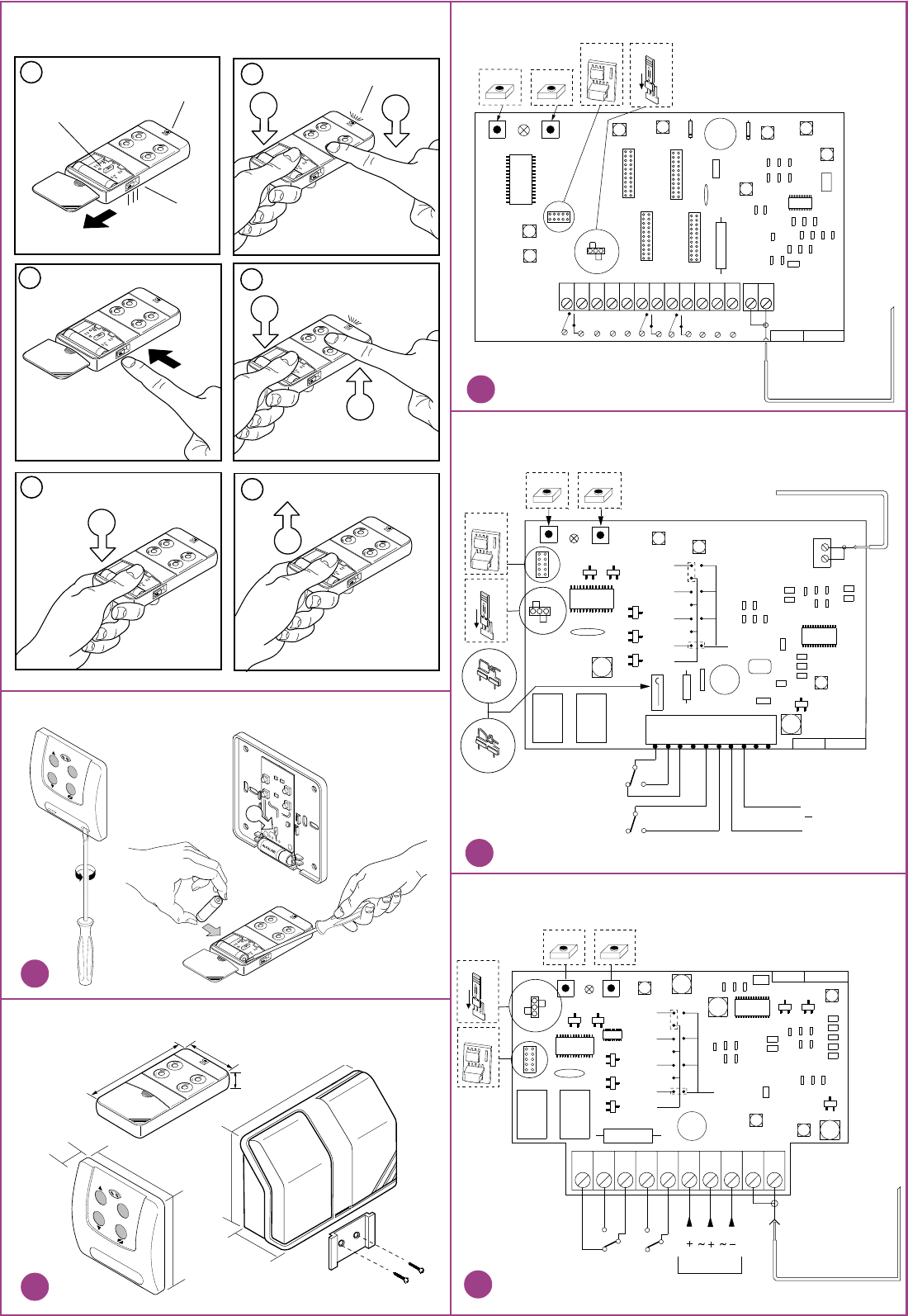
Modular receivers
Slot-in receiver cards
Mini receivers 1 -2 channels
GENERATING THE TRANSMITTER CODE
ALKALINE
3
J1
ALKALINE
123
J1
Y1
1L1
4
ALKALINE
J1 CH
L1
ALKALINE
6
J1
ALKALINE
2
Y1
ALKALINE
5
J1
CH
12
39
80
ALKALINE
ALKALINE
External dimensions
Changing the battery
116
138
45
11
7
8
9
10
CH D-H-N
CH C-G-M
CH A-E-I
CH B-F-L
+24
NA NC C
~
+12
~
-0
~
1 2 3 4 5 6 7 8 9 10 11 12 13 14
M1
P1 P2
1
2
J1
J1
L1
J1/J2 OFF A-B-C-D
J1 ON E-F-G-H
J2 ON I-L-M-N
ASAGSH Q
DFER 139
KJHG 1254
DC0217 CS926A/B
Antenna filo rigido 17cm
17 cm rigid wire antenna
Antenne fil rigide 17 cm
Starres Antennen Kabel 17 cm
Antena cable rígido 17 cm.
P1 P2
2
1
J1
J1
ASAGSH Q
DFER 139
KJHG 1254
CH 1
CH-D
CH-C
CH-B
CH-A
CH-2
CH-1
CH 2
RELAY CONTACT
CH2
RELAY CONTACT
CH1 POWER SUPPLY
+ 12 - 24 V ac/dc
12
0
~
Antenna filo rigido 17cm
Antenna rigid wire 17cm
M1
L1
24V
12V
Pos.A
Pos.B
DC0220 CS939A/B
P1 P2
2
1
J1
J1
ASAGSH Q
DFER 139
KJHG 1254
CH 2
CH-A
CH-B
CH-C
CH-D
CH-2
CH-1
CH 1
CH2
M1
L1
12345678910
OUT
CH1
OUT
DC0181 CS938A/B
24V 012V
Alimentazione
Power supply
Antenna filo rigido 17cm
17 cm rigid wire antenna
Antenne fil rigide 17 cm
Starres Antennen Kabel 17 cm
Antena cable rígido 17 cm.
ALKALINE
STOP
J1
82
20
82
STOP
MOD:20-10-2000
ZVL379.00 S435 20-10-2000
RXPR
CARDIN ELETTRONICA spa
Via Raffaello, 36- 31020 San Vendemiano (TV) Italy
Tel: +39/0438.401818
Fax: +39/0438.401831
email (Italy): Sales.office.it@cardin.it
email (Europe): Sales.office@cardin.it
Http: www.cardin.it
Warning: Changes or alterations made to this device which have not been expressly approved by the party
responsible for compliance with the local standards and regulations could cancel the user's authority to
operate the equipment.
NOTE: This equipment has been tested and found to comply with the limits for a class B digital device,
according to part 15 of the FCC rules. These limits are designed to provide reasonable protection against
harmful interference to radio communications.
However, there is no guarantee that interference will not occur in a particular installation. If this equipment
does cause harmful interference to radio or television reception, which can be determined by turning the
equipment off and on, the user is advised to try to correct the situation by taking one or more of the following
measures:
• Reorientate or relocate the receiving antenna
• Increase the distance between the equipment and the receiver
• Connect the equipment to a wall socket which is on a different ring circuit to that of the receiver
• Consult your dealer or an experienced radio/TV technician for help.
Description
The S435 radioprogramming system consists of one or more transmitters and one or more
receivers which can be combined to meet the specific needs of the system.
The S435 system uses a highly reliable encoding system guaranteed by the use of dynamic
codes. The code is changed for each encoding transmission through the use of an encoding
algorithm which only the receiver is able to recognise and therefore decide whether or not the
code transmitted corresponds to the original code. The code is generated for each channel in
the transmitter using the random arbitrary method with 236 combinations. The generated code
is memorised in the receiver via radio. The receiver is able to memorise up to 24 different
codes. During the transfer stage the codes are memorised in a non volatile memory module
which can be moved to another receiver without having to reprogram it. As this is a system
based on dynamic codes each code is processed individually by the receiver.
Important
Disturbance during the transmission will disactivate the relay, at this point the relay can only be
activated by first releasing and then pressing the transmitter channel button a second time.
Use
The radioprogrammer is best used in systems controlling automatic rolling shutters and allows
the remote activation of a single phase 115Vac 350W motor using dynamic commands Open-
Stop-Close-Stop or the same commands by cable. During the code memorisation phase the
channel can be associated (using the Dipswitch SW1) with one of the following functions: stop
command only; open command only or sequential dynamic commands "Open-Stop-Close-
Stop". This allows you to either control one motor or more than one motor contemporaneously
using one channel for the complete opening command, one channel for the complete closing
command and one channel for the single movement command.
Transmitter versions
TRS435200.0US Miniaturised transmitters 2 Buttons
TRS435400.0US Miniaturised transmitters 4 Buttons
TRS435120.0US Miniaturised transmitters with switch (12 channels) 4 Buttons
TRS43540M.0US Wall mounted transmitters 4 buttons
Receiver version
RPS435000.0US Radioprogrammer
Memory module
This is extractable, furnished with a non volatile EEPROM type memory and contains the system
codes. The programmed code is maintained in this module even in the absence of power. This
component can be ordered as an accessory with s.p.n. code: MCC46320
Receiver antenna installation
Minimum and maximum range of the radio controls. ‘Range’ is intended to mean the working
distance, measured in free space, between the receiver and the transmitter with the antenna
installed. The range is therefore closely linked to the technical characteristics of the system
(power and sensibility) and varies according to the characteristics of the site in which the system
is located. To obtain the best results from the device the installation sites for the receiver and
the antenna should be carefully chosen.
It is not possible to install 2 receivers at a distance of less than 1.5 m. from each other.
It is good practise to position the receiver away from computer systems, alarm systems and
other possible sources of disturbance. (A bad choice of positioning could compromise
the correct performance of the receiver).
Antenna
The installation of the antenna is fundamental, connected to the receiver it represents the
reception point for the radio control. When installing the antenna consider the following points:
The receiver is supplied with its own antenna which consists of a piece of rigid wire 170 mm
in length. In alternative it is possible to connect an ANS400 tuned antenna using a coaxial cable
RG58 (impedance 50Ω) with a maximum length of 15 m. The antenna should be positioned out
of doors in the highest possible point, visible and away from metal structures.
Receiver
The receiver is installed using “fast-fitting” brackets. The bracket should be fixed to the wall
using two raw plugs ( check that it is square to the wall), the case can be then slid onto the bracket
therefore fixing it to the wall. The slot-in circuit located towards the bottom of the case can be
easily extracted to facilitate wiring up the device. If any repair work is necessary the case can
be easily extracted by pushing upwards the action of which will separate it from the bracket.
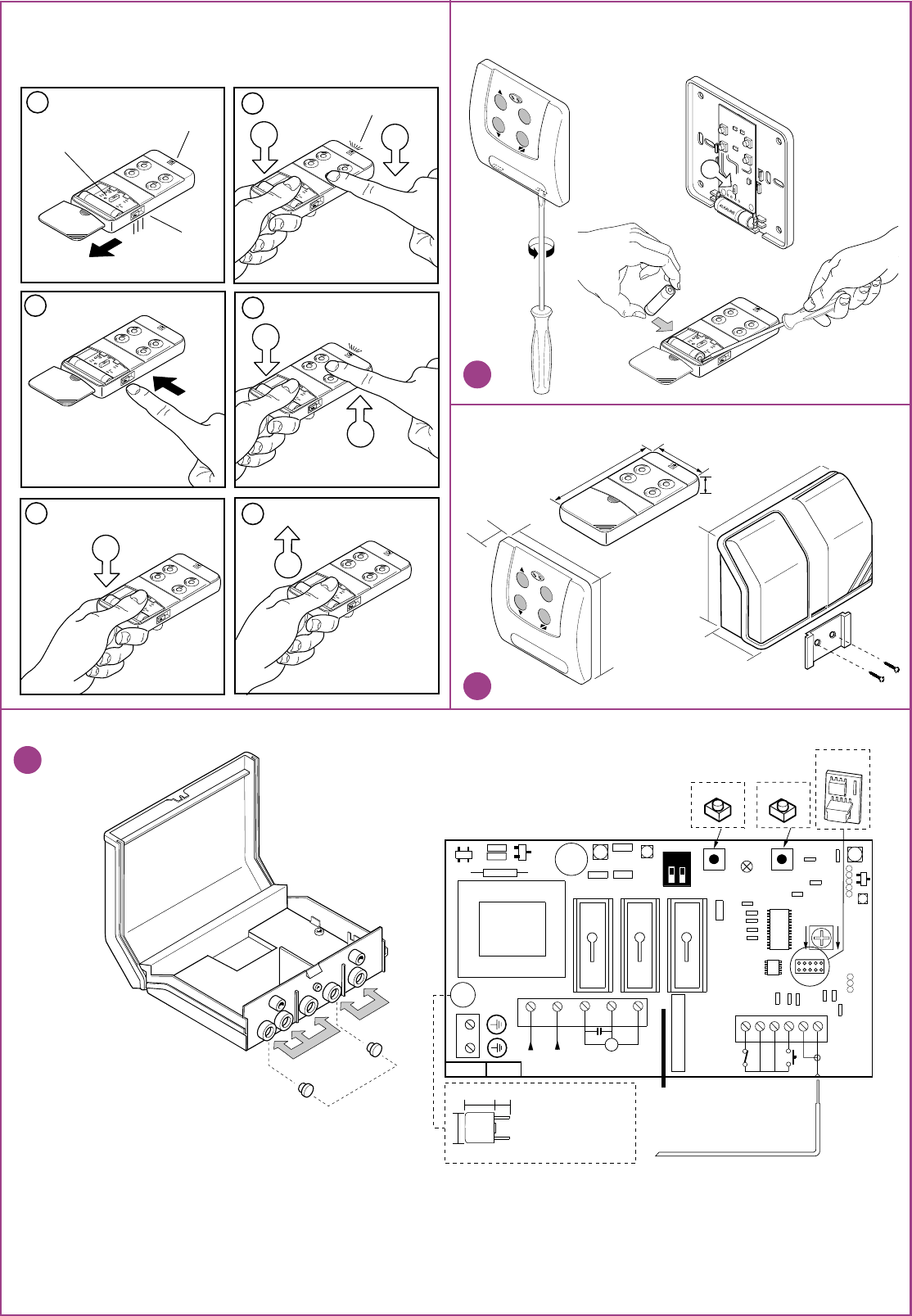
Electrical connection (fig.9)
Before connecting the device to the mains make sure that:
- the voltage and frequency rated on the data plate conform to those of the mains supply;
- an omnipolar circuit breaker which leaves at least 3mm between the contacts has been
installed between the device and the mains;
- the high voltage 115V wires pass through the holes marked "A" and are routed separately
from the low voltage 24V wires which pass through the holes marked "B";
- the wires are fastened down using a cable clamp;
- once the wiring is complete the holes through which the wires have passed have been sealed
using silicon;
- the holes which are not used are blocked by inserting the caps "D".
- the appliance must be earthed, to this end use the binding post marked with the symbol
which can be found on the wiring box.
Terminal board connections (fig. 9)
1-2 Earth connection
3-4 Radioprogrammer power supply 115Vac 50-60Hz.
5-6-7 Motor control in output "Open-Close-Common" 350W.
8 -9 N.C. input for safety devices with travel direction inversion during the closing cycle. If you
connect a pair of photocells an external power circuit will be required.
DIGITAL RADIOPROGRAMMER WITH DYNAMIC CODES S435
10-11 Dynamic button in input (contact N.O.) with Open-Stop-Close-Stop functions
12 Antenna ground.
13 Antenna connection 17cm rigid wire (as an alternative it is possible to connect an
ANS400 antenna using a coaxial cable RG58 (imp. 50Ω) with a maximum length of 15m).
Settings (fig. 9)
TL Work cycle regulation trimmer (15…80 secs).
The timer countdown starts after an opening or closing command has been received
and is set to zero after the preset work cycle time has expired. It cannot be set while
the motor is in movement.
PW Power on LED
F1 Fuse 4A delayed
Generating the user code in the transmitters (fig. 1-6)
• Once the container has been opened (see fig.7) the programming procedure for the wall
mounted transmitter is the same as for the hand held transmitter (the circuit is the same).
1) Open the access door (fig.1)
2) For the version equipped with a channel block selection switch choose the desired block of
channels by moving the switch ("Y1" fig.1,2)
Y1 in position "1" = A,B,C,D
Y1 in position "2" = E,F,G,H
Y1 in position "3" = I,L,M,N
3) Press the button "J1" (fig.3)
4) While keeping button "J1" pressed down press the button "CH" corresponding to the
required channel which is to be memorised. Led "L1" will start to flash (fig.4).
5) Release the channel button "CH" and the led will carry on flashing (fig.5).
6) Release the button "J1", the led will turn off and the transmitter will memorise the last code
which was transmitted (fig.6).
7) Repeat points 3-4-5-6 for any successive channels
8) To memorise another block of channels move the switch ("Y1" fig.2) to the required position
and repeat the operations 3-4-5-6.
If a code is not generated it could be due to the fact that the memory is empty and it is
therefore impossible to transfer the code to the receiver.
Generating the user code in the receiver (fig.9)
Attention! Before memorising the transmitters for the first time remember to cancel the
entire memory content.
Dipswitch SW1 functions
DIP1-DIP2 OFF
Code memorisation is not possible
DIP1 ON/ DIP2 OFF
The memorised code is associated with the opening command
DIP1 OFF/ DIP2 ON
The memorised code is associated with the closing command
DIP1 ON/ DIP2 ON
The memorised code is associated with the dynamic function
Open-Stop-Close-Stop
Memorising the user code in the receiver
1) Using dipswitch "SW1" select the function to be associated with the channel
2) Keep button "P1" pressed down and the led "LD" will start to flash
3) Transmit the channel which is to be memorised, the led will flash rapidly and the channel will
be memorised. Only one code can be inserted at a time. To insert successive codes repeat
steps 2 and 3.
- When you have finished memorising the codes remember to replace dips 1-2 in the off
position on "SW1".
If the code is not memorised it could be due to the following:
- The memory is full (24 codes already memorised) and the led remains lit. If this is the case
you can only insert a new code after you have first cancelled an existing one or after wiping
the entire memory (see memory cancelling procedure);
- The code may already exist in memory;
- You have not generated a channel code in the transmitter.
Memory cancelling procedure:
1) Keep the button "P2" pressed down and the led "LD" will flash slowly.
2) Transmit the channel which is to be cancelled for at least 3 seconds until the led starts to
flash quickly then repeat points 1 and 2 for any successive channels.
To wipe all the codes from memory:
3) Keep buttons "P1" and "P2" pressed down simultaneously for at least 5 seconds until the led
"LD" flashes rapidly .
Receivers
The receiver can decode up to 12 different channels in blocks of 3 (A,B,C,D - E,F,G,H - I,L,M,N.)
without a selection.
TECHNICAL SPECIFICATIONS
RECEIVER
- reception frequency ........................................................................................... 433,92 MHz
- local oscillation emission ........................................................................... <-57dBm (<2nW)
- antenna impedance in input ........................................................................................... 50Ω
- sensitivity (finely tuned signal) ....................................................................................... 1 µV
- power supply .............................................................................................115Vac 50-60 Hz
- operating temperature range ............................................................................ -20°…+60°C
TRANSMITTERS
- carrier frequency ................................................................................................ 433.92 MHz
- carrier frequency tolerance ...................................................................................... ±75 kHz
- band width ............................................................................................................... >25 kHz
- modulation ............................................................................................................... AM/ASK
- power supply (alkaline battery GP23A)................................................................12V ± 10%
- maximum power consumption ................................................................................... 25 mA
- operating temperature range ............................................................................ - 10…+55°C
MODEL DATE
CODE Nr. SERIES
This product has been tried and tested in the manufacturer's laboratory,
during the installation of the product follow the supplied indications
carefully.
2
1
2
1
2
1
2
1
GENERATING THE TRANSMITTER CODE
ALKALINE
3
J1
ALKALINE
123
J1
Y1
1L1
4
ALKALINE
J1 CH
L1
ALKALINE
6
J1
ALKALINE
2
Y1
ALKALINE
5
J1
CH
RADIOPROGRAMMER ELECTRICAL CONNECTION
Legend
A: Entry holes for 110V~ mains wiring
B: Entry holes for low voltage 12/24V wiring + antenna
C: Separator wall
D: Hole sealing plugs
LD: Signal led
M1: Memory module
P1: Memorising button
P2: Delete button
PW: Power on led
SW1: Function selection dip
TL: Work cycle setting trimmer
+
-TL
34567
M8 9 10 11 12 13
PW
FUSE
3.15
A
FTC
TD
AP.
COM
CH.
8,4
8,4
4.3
P1 P2
DC0225 CS951
M1
ASAGSH Q
DFER 139
KJHG 1254
12
F
N
220/230V~
c
1 2
ON
SW1
Antenna filo rigido 17cm
17 cm rigid wire antenna
Antenne fil rigide 17 cm
Starres Antennen Kabel 17 cm
Antena cable rígido 17 cm.
LD
F1
F1: Fuse type
Current T3,15A
Code MT785231
I2t A2S 60
Voltage drop mV 100
12
39
80
ALKALINE
ALKALINE
EXTERNAL DIMENSIONS
BATTERY REPLACEMENT
116
138
45
ALKALINE
STOP
J1
82
20
82
STOP
7
8
B
A
C
D
9