Carestream Health 5700 DRYVIEW 5700 Laser Imager User Manual 9G3886 en A
Carestream Health, Inc. DRYVIEW 5700 Laser Imager 9G3886 en A
Contents
- 1. User Manual 1
- 2. User Manual 2
User Manual 1
User’s Guide

Carestream Health, Inc.
150 Verona Street
Rochester, New York 14608
© Carestream Health, Inc., 2011
Pub No. 9G3886_en
Rev. A

i
Table of Contents
1 Overview
Major internal assemblies............................................................................................................................... 1-2
How the laser imager works ............................................................................................................................1-3
Film sizes ........................................................................................................................................................1-4
Automatic image quality and processing ..........................................................................................................1-4
Configuring and monitoring the system (using the Web Portal) .......................................................................1-4
Enhancing serviceability with remote monitoring ............................................................................................1-5
Agency compliance ......................................................................................................................................... 1-5
User guide conventions ...................................................................................................................................1-5
2 Basic Operating Tasks
Understanding the display screen ....................................................................................................................2-2
Turning the power on and off ..........................................................................................................................2-3
Working with film cartridges ...........................................................................................................................2-5
Deleting pending jobs .....................................................................................................................................2-8
Making a test print ..........................................................................................................................................2-8
Calibrating the laser imager for the installed film ............................................................................................2-9
Opening or removing a cover ..........................................................................................................................2-9
Using the Web Portal to access additional functionality .................................................................................2-10
3 Maintenance and Troubleshooting
Overview: Status and error messages and codes ..............................................................................................3-1
Preventive maintenance ...................................................................................................................................3-2
Error indicators on the display screen ............................................................................................................3-4
Using the Web Portal to gain more information on errors .............................................................................. 3-5
Subsystem error codes and messages ..............................................................................................................3-5
Condition codes ..............................................................................................................................................3-9
Correcting film jams ......................................................................................................................................3-14
Display Screen is not functional ....................................................................................................................3-18
Calling for support ........................................................................................................................................3-18
4 Film Technical Information
General description .........................................................................................................................................4-1

ii
5 Specifications
Equipment Specifications ................................................................................................................................5-1
Operating Space Requirements .......................................................................................................................5-1
Environmental Requirements ..........................................................................................................................5-1
Environmental Effects .....................................................................................................................................5-2
Power Requirements .......................................................................................................................................5-2
Network Requirements ...................................................................................................................................5-2
Overview
2011-03-31 9G3886_en 1-1
1
Overview
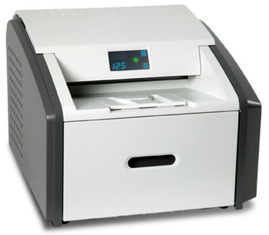
The Laser Imaging System is a continuous-tone laser imager with an
internal photothermographic film processor. Heat, rather than photo
chemicals, is used to develop the film. This easy-to-use and reliable laser
imager provides high quality prints. Use the prints from this system for:
• Diagnostic purposes to determine patient treatments
• Referral, sharing, or educational purposes
The system receives and prints from image sources such as medical
electrical equipment (modalities) and workstations over the network.
You can send print jobs simultaneously from multiple image sources.
The open design lets you connect to modalities of all types and vendors.
IMPORTANT: Install the printing system in a secure location to protect
patient privacy rights if required by local regulations.
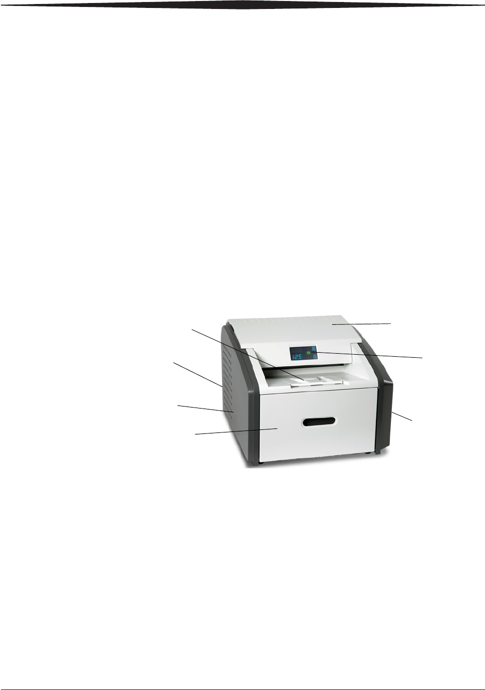
1Top cover. Covers the processor rollers. The top cover is interlocked.
2 Display screen. Your interface to the laser imager. Provides status and
error information.
3Right cover. Protects sensitive electronic equipment. The right cover
is interlocked and is only accessed by service personnel.
4 Film supply. Install film cartridges here. Supports four film sizes.
5 Left cover. You might remove the left cover to clear an occasional
film jam. The left cover is interlocked.
6 Power switch. The power switch is on the back.
7 Exit tray. Extend the exit tray to hold large film (35 x 43 cm, or
14 x 17 in.) as it finishes printing. It can hold up to 50 processed sheets
of film.
4
71
2
3
5
6
1-2 9G3886_en 2011-03-31
Overview
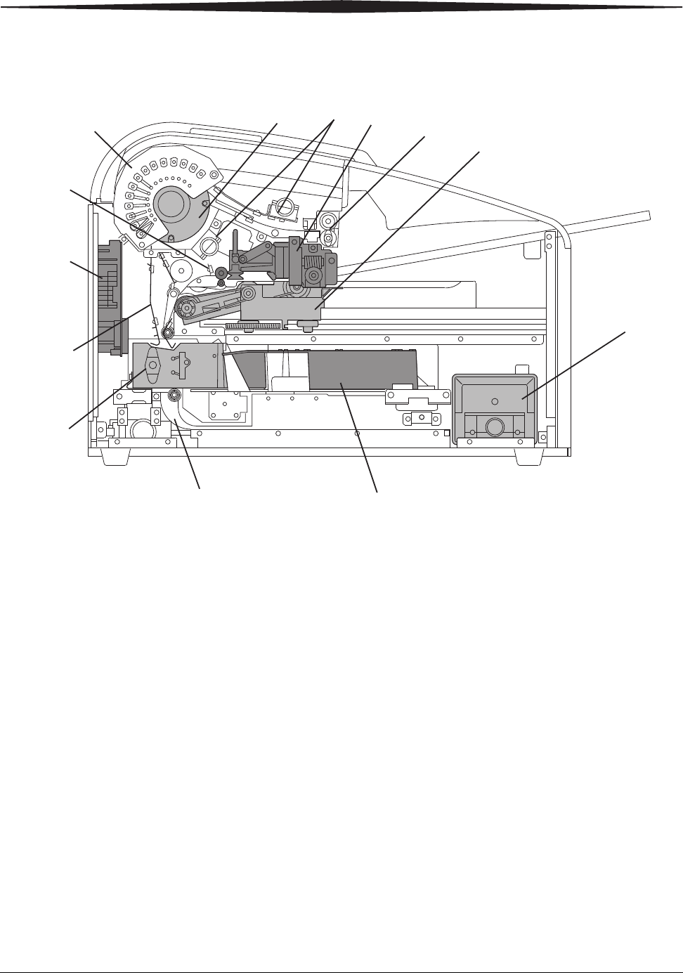
Major internal assemblies
1Exposure transport. Moves the film past the scanning laser beam.
2Transport guides. Orient and center the film while moving the film from the supply to the imaging
portion of the laser imager.
3DICOM Raster Engine (DRE). A computer board that receives, processes, and manages the images.
4Feed rollers. Move the film through the laser imager.
5Processor rollers. The processor uses heat to develop the image written onto the film by the laser in the
optics module. The rollers move the film through the processor assembly, holding the film against the
processor drum.
6Processor drum. Provides the heat that processes the image on the film.
7Airflow manifolds. Remove heat and processing odors from the processor assembly.
8Pickup assembly. Lifts a single sheet of film from the supply cartridge and feeds it into the rollers.
9Exit rollers. Moves the film from the processor area to the exit tray.
10 Rollback assembly. Rolls the film cartridge cover back so the pickup assembly can lift the film. When
the laser imager is not printing, the cover is closed over the film cartridge to protect the film from light.
11 Charcoal filter. Absorbs the odors caused by heat processing.
12 Optics module. Writes the image onto the film while the film is moved through the exposure transport.
13 Accumulator. The film feeds into the accumulator as it is imaged. When imaging is complete, the film
is sent from the accumulator up to the processor assembly where the heat is applied to process the image.
H210_1012HC
1
2
3
4
5
678
9
10
11
12
13
Overview
2011-03-31 9G3886_en 1-3
How the laser imager works
The laser imager receives, processes, manages, and prints the images on
film. The laser imager has limited storage to hold a small number of
digital images. As images are received for printing, they are stored in
memory, placed in a sequential print queue, and are printed in order. The
laser imager can continue to accept incoming print jobs even if
temporarily unable to print (if the film supply is empty, etc).
During normal operation, the laser imager requires very little attention. It
prints automatically in response to print requests from the configured
image sources. Information sent with the images by the image source,
such as film type and size and image quality settings, is applied unless
you set the laser imager to override information that comes from the
image source.
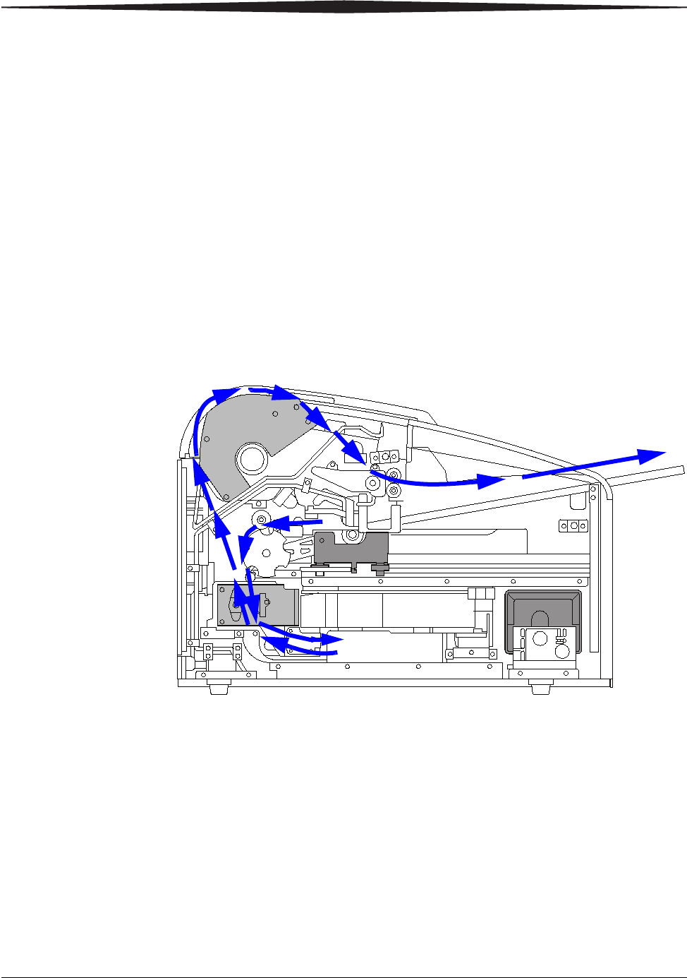
Print sequence
Each time the laser imager receives a print request, the following print
sequence occurs. The blue arrows show the film path.
1. Suction cups in the pickup area lift a single sheet of film out of the
supply cartridge and feed the film into the transport rollers.
2. The transport rollers move the film down into the exposure transport
area.
3. The film moves down during imaging (as the optics module writes
the image onto film), reverses direction at the conclusion of
imaging, and then the film moves up into the processor.
4. As the film passes over the processor drum, the heat generated by
the drum develops the film.
5. The exit rollers move the developed film to the exit tray.

1-4 9G3886_en 2011-03-31
Overview
Film sizes
The laser imager supports four sizes:
• 35 x 43 cm (14 x 17 in.)
• 28 x 35 cm (11 x 14 in.)
• 25 x 30 cm (10 x 12 in.)
• 20 x 25 cm (8 x 10 in.)
For the specific films that are supported, see the Publications Cover
Page.
Automatic image quality and processing
An internal densitometer enables the laser imager to automatically adjust
image processing parameters (Automatic Image Quality Control, or
AIQC) to produce an optimal image. The laser imager adjusts these
parameters each time it prints a calibration film.
A calibration film is printed when:
• The film tray is inserted in the laser imager with film of a new lot
number.
• You request a calibration film at the display screen or the Web
Portal. For more information, see “Calibrating the laser imager for
the installed film” on page 2-9.
• A film cartridge is inserted into the laser imager for which a current
calibration is not stored.
Configuring and monitoring the system (using the Web
Portal)
The Web Portal is your interface to additional features. In addition to
the installation and setup of your system, you can view and manage the
laser imager's connections over the network, configure features, view
error messages, and access general status information at the Web Portal.
You can also check film count, film size, and film type.
For more information, see “Accessing the Web Portal” on page 2-10.
Overview
2011-03-31 9G3886_en 1-5
Enhancing serviceability with remote monitoring
Remote Management Services is set up through the Web Portal, and is
designed to enhance efficient system serviceability and simplify
analytical and service processes through the monitoring of your
equipment. Additionally, this simplifies the service process by providing
qualified service personnel with faster, easier, and more complete access
to the operational history of each system.
Remote Management Services provides the following for the laser
imager:
• Ability to monitor and diagnose error conditions without
introducing “downtime”
• Firewall-safe, Internet transmission of machine data, while
complying with patient confidentiality regulations
• Minimal effort to set up communication
• Flexibility to facilitate specific configurations at each site
Agency compliance
See the Safety Manual.
User guide conventions
The following special messages emphasize information or indicate
potential risks to personnel or equipment.
NOTE: Notes provide additional information, such as expanded explanations,
hints, or reminders.
IMPORTANT: Important notes highlight critical policy information that
affects how you use this guide and this product.
CAUTION:
Cautions point out procedures that you must follow precisely to
avoid damage to the system or any of its components, loss of
data, or corruption of files in software applications.
DANGER: DANGER IDENTIFIES PROCEDURES THAT YOU
MUST FOLLOW PRECISELY TO AVOID INJURY TO
YOURSELF OR OTHERS.
LASER WARNING:
Laser warnings warn personnel that access to laser radiation is
possible and all personnel must avoid direct exposure to the
beam.

Basic Operating Tasks
2011-03-31 9G3886_en 2-1
2
Basic Operating Tasks
During normal operation, the laser imager receives and automatically
prints images sent by modalities over a network. Very little interaction is
required. You may do the following:
• Turn the power on (|) and off (0).
• Load film cartridges.
• Monitor the display screen for status and operating conditions.
Sometimes it will be necessary to perform preventive maintenance, filter
replacement, and other corrective actions such as a restart. (See
“Chapter 3 Maintenance and Troubleshooting”.)
You also may access the Web Portal to perform additional configuration,
optimize image quality, or do troubleshooting tasks. (See page 2-10.)
2-2 9G3886_en 2011-03-31
Basic Operating Tasks
Understanding the display screen
The display screen communicates the status of the laser imager.
Symbol or code Description
Top left of the
display screen:
Error or status code. The 3-digit code displays when the error or status condition is present.
See “Chapter 3 Maintenance and Troubleshooting” for a complete list of the codes and how
to resolve them. If the laser imager is on and a 3-digit code does not display, the laser
imager is operating normally.
If a different film size has been requested than what is installed, the requested film size
displays. See “Loading a different film size to match a print request” on page 2-7.
Lower left of the
display screen:
Film count. Displays the number of films that are remaining in the film cartridge.
The loaded film size also displays in this location.
Power When the symbol is green, the power is on and the laser imager is ready to print. The
symbol flashes while the laser imager is processing.
When the symbol is yellow, the laser imager is not ready to print. Examples are when the
laser imager is warming up or when the film cartridge is empty.
Calibrate Press to initiate film calibration. The symbol flashes while the calibration is in process. See
“Calibrating the laser imager for the installed film” on page 2-9.
Pause During normal operation, the symbol is off. When the film cartridge cover is open, the
symbol is on. To avoid exposing the film to light, do not open the film supply until the
symbol is off.
If the Pause symbol is on, you can press the symbol to temporarily pause printing. Any
jobs in progress finish printing, then the film cartridge cover closes.
Wait until the Pause symbol is off for cartridge replacement, etc.
Film Size When the symbol appears, the requested job requires a different film size. See “Loading a
different film size to match a print request” on page 2-7.
You can also delete a print request. See “Deleting pending jobs” on page 2-8.
Restart Restart the laser imager. An error code also displays. See “Restarting the laser imager” on
page 2-4.
Film Jam Film is jammed. The error code confirms the film jam and gives direction on where to find
the film inside the laser imager. See “Film jams” on page 3-4.
Maintenance Preventive maintenance is required. Check the error code to learn what action to take. See
“Preventive maintenance” on page 3-2.
Basic Operating Tasks
2011-03-31 9G3886_en 2-3
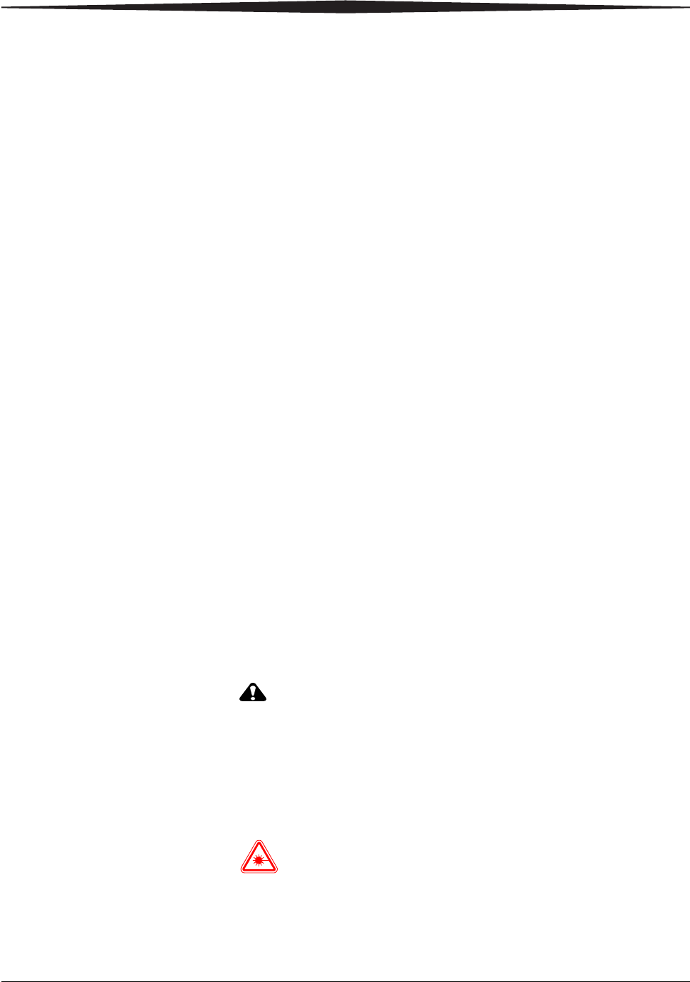
Turning the power on and off
To start the laser imager, press the power switch on the back of the laser
imager to on (|). Wait as the laser imager warms up. The warm-up period
might last up to 30 minutes. The display screen shows the progress as the
laser imager becomes ready to print.
Warming up
The warm-up period varies depending on the amount of time the laser
imager has been off and the ambient temperature. During warm-up, the
laser imager can receive and store images but cannot print films.
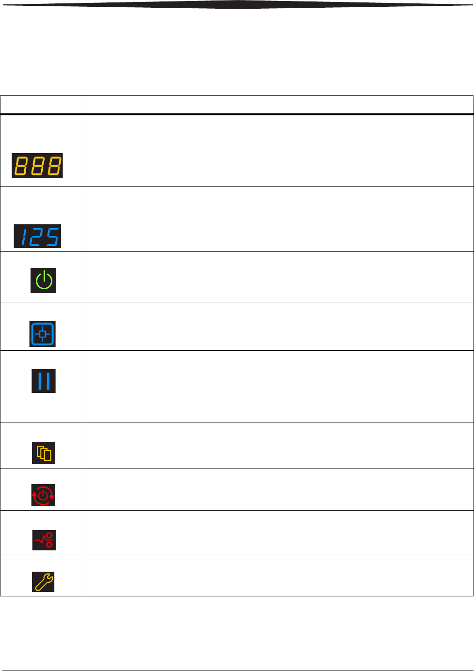
When the laser imager reaches operating temperature, the display screen
changes to show that the system is ready to print, and the laser imager
prints images that were received during the warm-up period.
Ready to print
Emergency shutdown
or power loss In the event of a power loss, or if an emergency requires an immediate
shutdown of the laser imager, films in process will not be completed.
However, when power is restored, the laser imager will restart. After
warming up, the laser imager automatically reprints any films that were
in process when the power was interrupted.
The power symbol is
yellow and flashing
while the laser
imager warms up
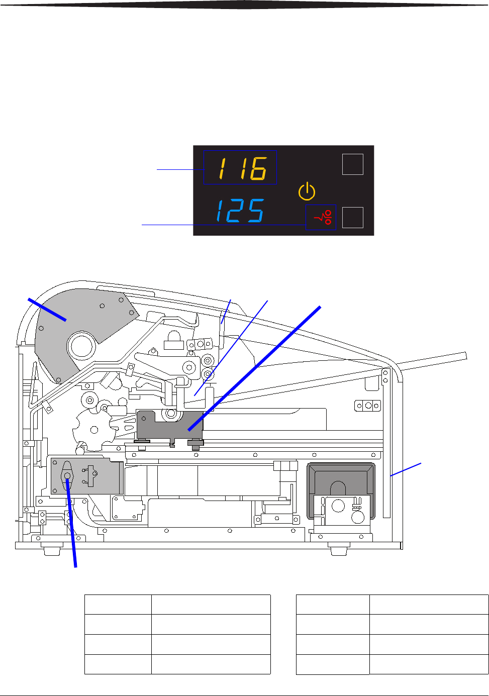
A countdown to zero (0) indicates
how soon the laser imager will be
ready to print
Film count
Green power symbol means "ready"
You can
calibrate the film
cartridge if
necessary

2-4 9G3886_en 2011-03-31
Basic Operating Tasks
Restarting the laser
imager If the laser imager encounters an error that is usually corrected with a
restart, the display screen shows the Restart symbol.
1. Press the power switch on the back of the laser imager off (0).
2. Press the power switch on (|).
If the error does not clear with after the restart, it might be necessary
to contact a qualified service provider.
Restart
The error code indicates
the error condition. You
may want to check the
“Troubleshooting” chapter
or the Quick Reference
Card to identify the error.
Basic Operating Tasks
2011-03-31 9G3886_en 2-5
Working with film cartridges
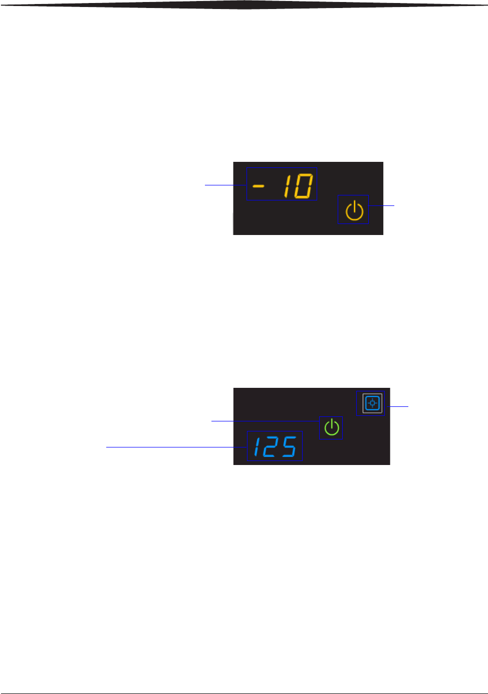
Checking film count The film count displays on the laser imager display screen.
Checking the size of
the loaded film The film size displays in the same location as the film count. The display
screen alternates between the film count and the size of the loaded film.
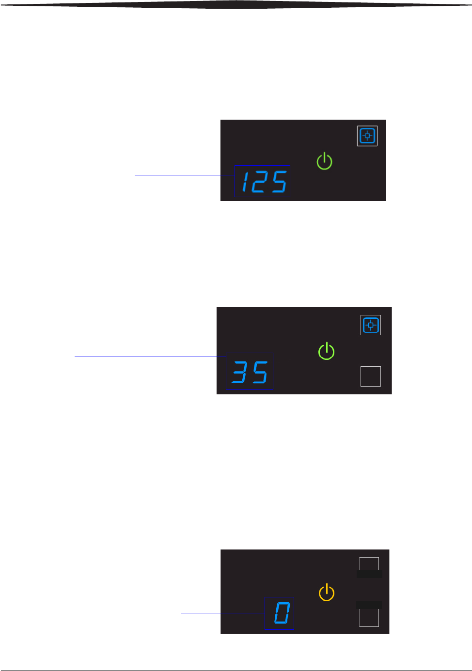
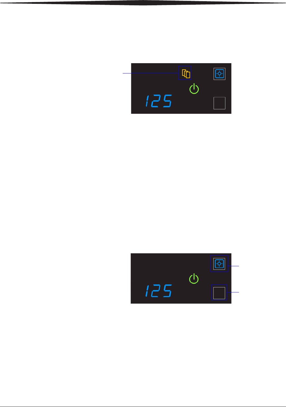
Film count is flashing
"0" When the film cartridge is empty, the film count flashes "0" and the
power symbol is yellow, which indicates that the laser imager cannot
print. Replace the film cartridge with a new one with the appropriate size
film. See page 2-6.
Film count
125 indicates a full cartridge
Film size
"35" indicates the 1st dimension of the
film cartridge. For example, "35" then
"43" appears if 35 x 43 cm film is
loaded. Then the film count displays
again.
When the film count is "0", you
must replace the film cartridge
before you can print again
2-6 9G3886_en 2011-03-31
Basic Operating Tasks
Inserting a new film
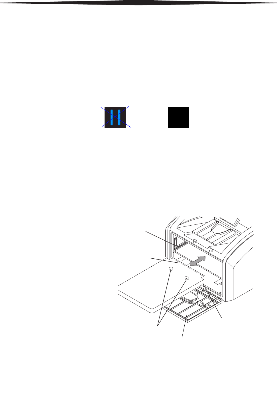
cartridge Before you insert a new film cartridge, make sure that the Pause symbol
is off. During normal operation, the symbol is off. When the film
cartridge cover is open, the symbol is on. To avoid exposing the film to
light, do not open the film supply until the Pause symbol is off.
If the Pause symbol is on, press the symbol to close the film cartridge
cover.
1. Open the film supply. Hold the edges of the film cartridge and lift
the empty cartridge out of the film supply.
2. Discard the removed cartridge.
3. Insert the new film cartridge. Align the cartridge with the label
facing up and the perforations to the front. Set the leading edge on
the cartridge guides, and then slide the film cartridge into the laser
imager to engage the detents in the bottom of the cartridge.
4. Close the film supply.
5. Check that the display screen changes to reflect the new film count.
Make sure the Pause symbol is off (not illuminated)
before you insert a new film cartridge.
Pause symbol is on Pause symbol is off
H210_1020AC
H210_1020ACA
Leading Edge
Detents
Perforations
Cartridge
Guide
Film Supply
Basic Operating Tasks
2011-03-31 9G3886_en 2-7
Loading a different
film size to match a
print request
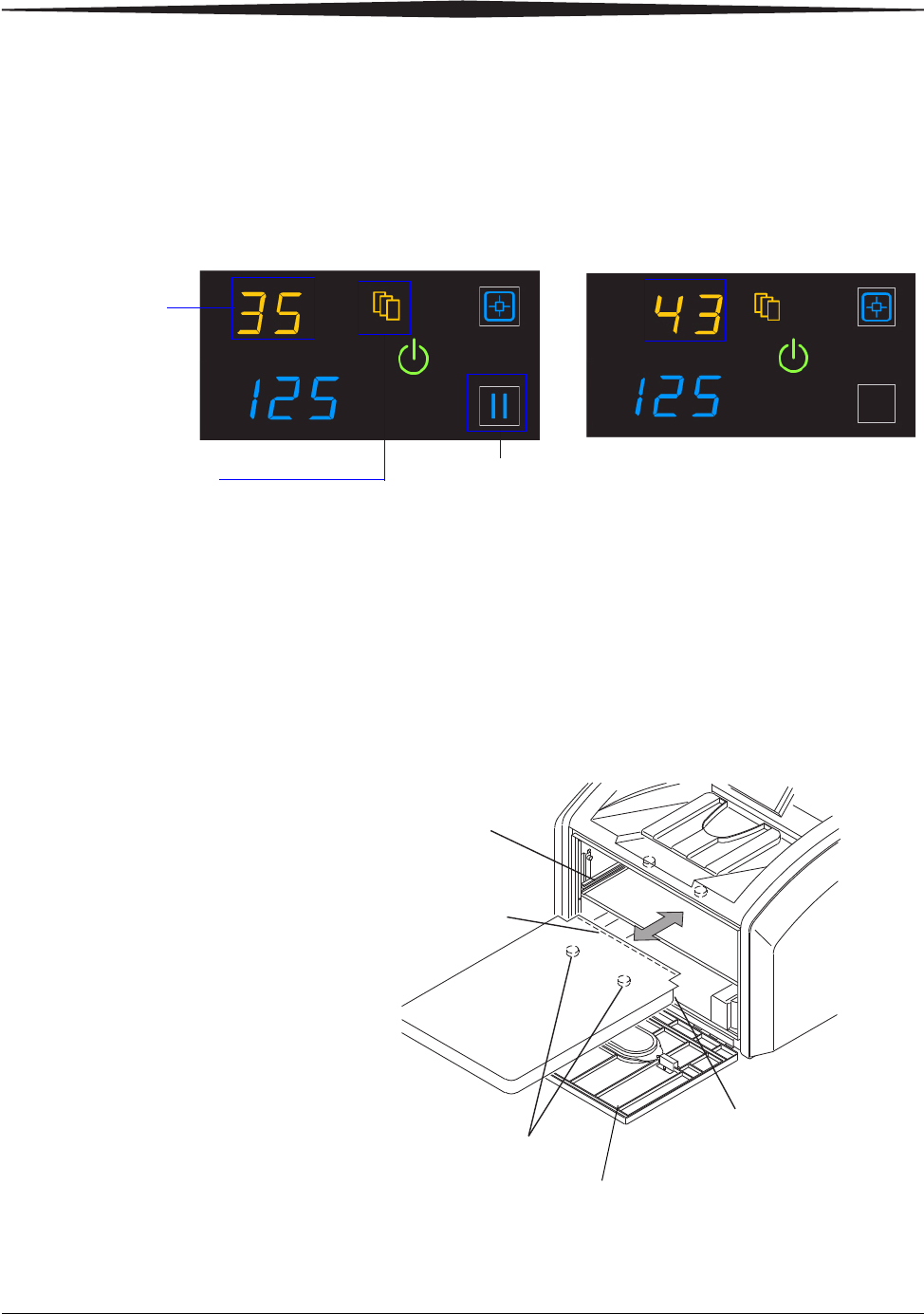
If a print request requires a different film size, the requested film size
flashes on the display screen. Change the installed film to match the print
request.
1. If the Pause symbol is on, press it and wait until it goes off.
2. Open the film supply. Hold the edges of the film cartridge and lift
the cartridge out of the film supply.
3. Store the removed film cartridge.
4. Insert the new film cartridge. Align the cartridge with the label
facing up and the perforations to the front. Set the leading edge on
the cartridge guides, and then slide the film cartridge into the laser
imager to engage the detents in the bottom of the cartridge.
5. Close the film supply.
6. Check that the display screen changes to reflect the new film size.
The requested film
size flashes. In this
example, load
35 x 43 cm
(14 x 17 in.) film.
The Film Size symbol
indicates that you
must change the film size.
Screen 1: "35" flashes Screen 2: "43" flashes
In most cases, the Pause symbol is off. Do not open the film
supply if the Pause symbol is on. The Pause symbol indicates
that the film cartridge is open.
H210_1020AC
H210_1020ACA
Leading Edge
Detents
Perforations
Cartridge
Guide
Film Supply
2-8 9G3886_en 2011-03-31
Basic Operating Tasks
Deleting pending jobs
To cancel all print requests, press and hold the Film Size symbol for five
seconds. All print requests are deleted from the queue.
NOTE:
• A print request that cannot be printed is automatically deleted
from the laser imager. This situation could be caused by
invalid parameters from the modality, etc.
• If a job is not printable, the laser printer will eject a blank
film into the exit tray.
Making a test print
NOTE: You can make additional test prints at the Web Portal. For more
information, see “Accessing the Web Portal” on page 2-10.
Make a SMPTE test from the laser imager to check that you can print.
Press and then release the Calibration and Pause symbols. The symbols
flash until the test print is complete.
Press this symbol
for five seconds
Press these
two symbols at
the same time
for five
seconds
Basic Operating Tasks
2011-03-31 9G3886_en 2-9
Calibrating the laser imager for the installed film
In normal operating conditions, it is not necessary to calibrate the laser
imager for the film. Run a calibration when:
• Code 001 appears on the display screen.
• A calibration error occurs, indicated by codes 624, 631, or 632 on
the display screen.
• A "Not Calibrated" message appears on the Web Portal Home
screen.
The calibration initiates a test print with a step wedge pattern. The
pattern has a series of 21 step wedges of increasing optical density.
1. Press the symbol to start the calibration. The Calibration and Power
symbols both flash while the calibration is in progress.
2. When the symbols stop flashing, the calibration is complete.
NOTE: If the Calibration symbol turns from blue to yellow, there was a
problem with the calibration process. See “Calibration error” on
page 3-3.
Opening or removing a cover
You can open or remove the laser imager’s top cover, left cover, and film
supply. The covers are protected with an interlock mechanism to keep
the laser imager from printing when they are open, to keep you safe.
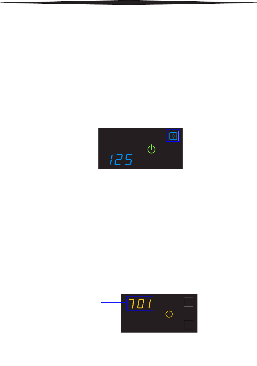
Code 701 alerts you that a cover and an interlock are open, and internal
power to the laser imager is turned off.
You might open the top or left cover to search for film jams. For more
information, see “Correcting film jams” on page 3-14.
Press to calibrate the laser
imager for the installed film
A cover is open

2-10 9G3886_en 2011-03-31
Basic Operating Tasks
Using the Web Portal to access additional functionality
The Web Portal is your interface to additional features. In addition to
the installation and setup of your system, you can view and manage the
laser imager's connections over the network, configure features, view
error messages and access general status information at the Web Portal.
You can also check film count, film size, and film type.
Troubleshooting tools include:
• Optimization of image quality for modalities.
• Retrieval of logs, statistics, and system status.
• Diagnostic utilities, including backup and restore.
The Web Portal provides an online Help system and a user’s guide to
assist you.
Accessing the Web
Portal To access the Web Portal, use a desktop or laptop computer that is
connected to the network.
1. On a desktop or laptop computer, start WINDOWS Internet
Explorer (version 6, 7, or 8).
2. In the address field, type: http://<laser imager’s IP address>
NOTE: If you do not know the IP address, check with your network
administrator or the person who installed the laser imager.
3. Click Go.
The main window for the Web Portal shows the general status, the
number of print jobs queued, the number of jobs waiting for film,
and the film count.
The center panel displays the screens where you view and perform
tasks. Online help is available by selecting Documentation from
the left panel, and the Help icon provides context-sensitive Help for
fields and pages.
The left panel also provides the links to all other screens.
NOTE: If you are using WINDOW Internet Explorer 8, place the
Internet Explorer window into compatibility view. After you
have opened the IE8 window, click the Compatibility View
toolbar button. This will correct some potential viewing issues
with IE 8. If the icon is not on the toolbar, select Compatibility
View from the Tools menu.

Maintenance and Troubleshooting
2011-03-31 9G3886_en 3-1
3
Maintenance and
Troubleshooting
Use the information in this chapter to keep the laser imager in the best
condition and to correct minor problems.
•“Overview: Status and error messages and codes” on page 3-1
•“Preventive maintenance” on page 3-2 - Learn how to respond to the
Maintenance symbol when it appears
•“Error indicators on the display screen” on page 3-3 - Learn about
the yellow and red error symbols
•“Using the Web Portal to gain more information on errors” on
page 3-5 - Learn how and why to access the Web Portal
•“Subsystem error codes and messages” on page 3-5 - A reference
section with all error codes and messages
•“Condition codes” on page 3-9 - A reference section with all
condition codes
•“Correcting film jams” on page 3-14 - Provides instructions to
locate and correct jammed films
•“Display Screen is not functional” on page 3-18 - Instructions if the
display screen is not responding
•“Calling for support” on page 3-18
Overview: Status and error messages and codes
The laser imager detects errors and other conditions and reports them to
you in multiple ways. Some conditions require your action. This section
provides a list of the codes, explains the condition, and provides
recommended actions where appropriate. View the codes:
• At the laser imager’s display screen, on the top left. The display
screen reports 3-digit codes.
Some codes are associated with symbols on the display screen, such
as the Film Jam symbol, to help you quickly understand the
condition.
• At the Web Portal. Access the Web Portal using your personal
computer, keyboard, and mouse to gain more information about the
errors and conditions. Using the Web Portal is optional but you may
find it useful. The Web Portal can report more information than the
laser imager’s display screen due to the limited size of the display
screen. See “Using the Web Portal to gain more information on
errors” on page 3-5.
3-2 9G3886_en 2011-03-31
Maintenance and Troubleshooting
Preventive maintenance
NOTE: These conditions are also reported at the Web Portal.
Replacing the filter
CAUTION:
In the U.S., exhausted filters are considered to be
non-hazardous waste according to the US Environmental
Protection Agency Resource Conservation Recovery Act
(RCRA). Municipality owned and licensed solid waste
management facilities are an appropriate disposal option.
Contact your local or state solid waste authorities to determine
if additional disposal requirements apply. In other regions,
contact local or regional solid waste authorities for proper
disposal guidance.
The charcoal filter controls processing odors in the laser imager. The
filter in the laser imager must be replaced after 7500 prints. Keep at least
one filter available to be ready to replace it when needed.
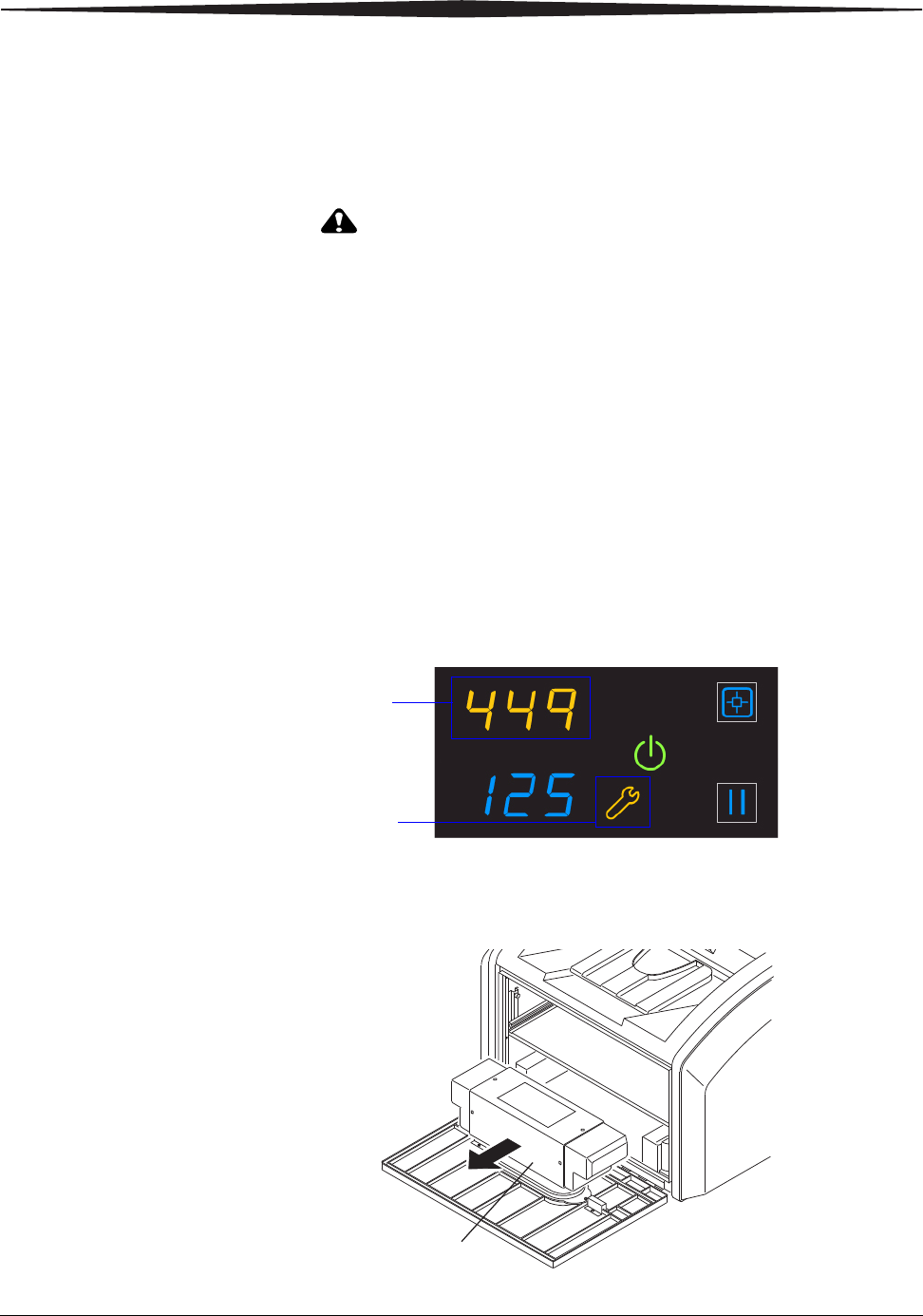
When the filter must be replaced, the display screen shows the error code
and the Maintenance symbol:
1. Open the film supply.
2. Remove the charcoal filter by lifting it up and pulling it forward.
Code 449 indicates that the filter
must be replaced
The system requires maintenance
H210_1016AC
H210_1016ACA
Charcoal
Filter
Maintenance and Troubleshooting
2011-03-31 9G3886_en 3-3
3. Install a new charcoal filter.
4. Close the film supply.
5. To reset the laser imager for the new filter and to clear the
Maintenance symbol, press and then release the Maintenance and
Calibrate symbols at the same time.
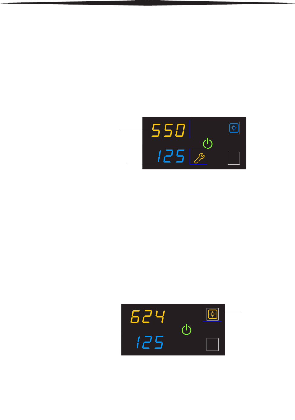
550 code and
Maintenance symbol If the laser imager needs a preventive maintenance service call, the 550
code and Maintenance symbol appear:
When the 550 code displays, contact a qualified service provider.
Error indicators on the display screen
The laser imager can detect errors and other conditions that require a
response. Some errors or abnormal conditions are reported on the display
screen in the form of condition codes and symbols.
NOTE: These errors are also reported at the Web Portal.
Calibration error When the calibration has failed, the display screen shows a 624, 631, or
632 error and the Calibrate symbol is yellow:
The most common cause is a film-related problem. Depending on the
cause, you may be able to keep printing, but the laser imager may not be
optimally calibrated.
The system requires maintenance
Code 550 indicates that the laser
imager requires a service call
Yellow symbol
indicates that the
calibration failed
3-4 9G3886_en 2011-03-31
Maintenance and Troubleshooting
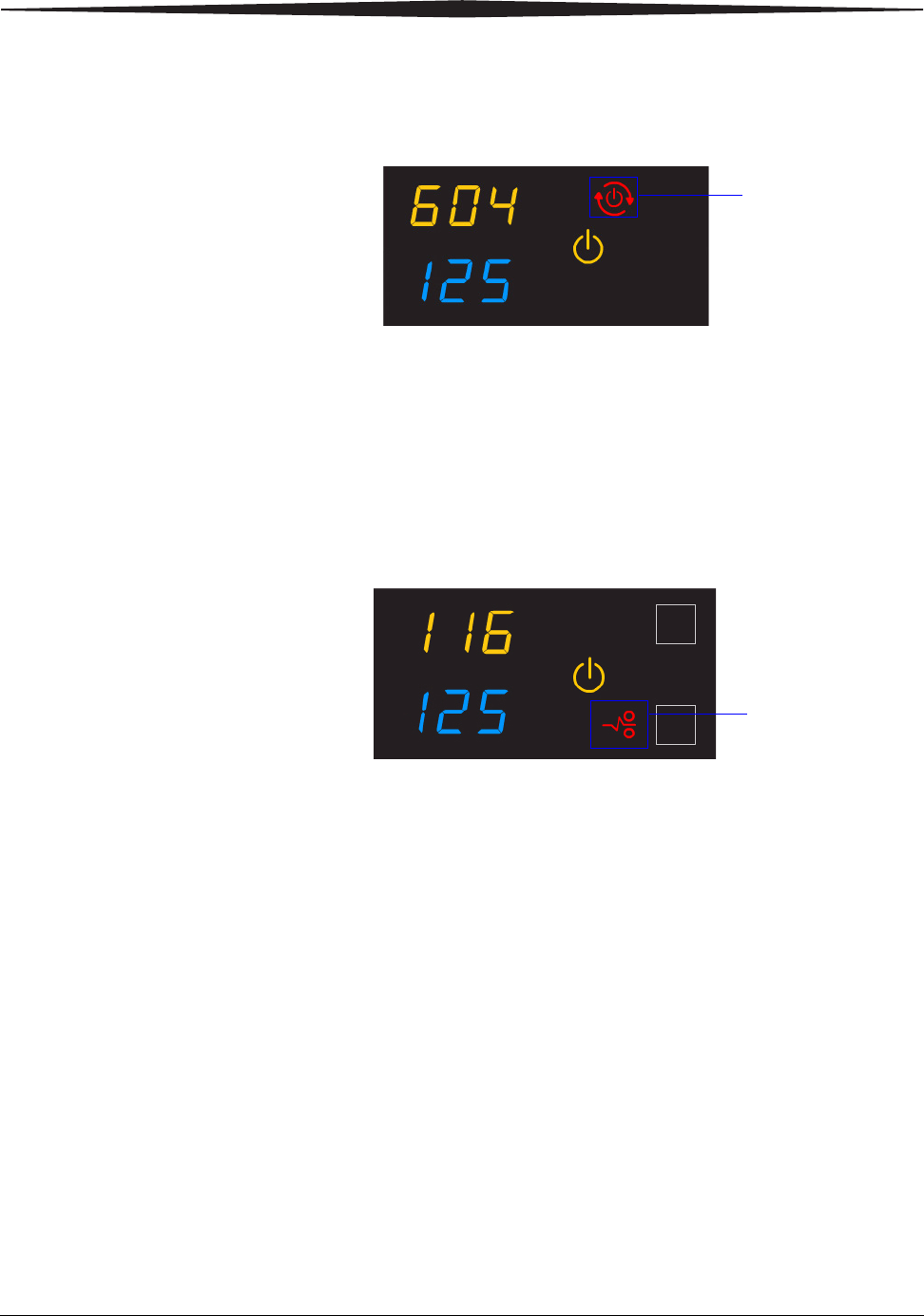
Required restart When the Restart symbol appears, you must restart before the laser
imager can continue to print.
1. Press the power switch on the back of the laser imager off (0).
2. Press the power switch on (|).
3. If the error does not clear, contact a qualified service provider.
Film jams When the Film Jam symbol appears, you must clear the jam before the
laser imager can continue to print.
See “Correcting film jams” on page 3-14 for instructions.
Restart the laser
imager
Film jam symbol
Maintenance and Troubleshooting
2011-03-31 9G3886_en 3-5
Using the Web Portal to gain more information on errors
The Web Portal is your interface to additional functions on the laser
imager. You can view and correct error messages and access general
status information at the Web Portal.
To access the Web Portal, see “Using the Web Portal to access additional
functionality” on page 2-10.
Understanding the
codes on the Web
Portal and the Display
Screen
The 3-digit error and status codes on the display screen are reported at
the Web Portal as 5-digit codes. The last three digits on the Web Portal
codes match the three digits on the display screen. For example, code
701 on the display screen is the same as code 20701 on the Web Portal.
Use the information in this section to understand the information at the
display screen and/or at the Web Portal and to respond appropriately.
Subsystem error codes and messages
Use the information in this section to interpret the codes and messages
that appear on the display screen and at the Web Portal.
DICOM (Digital
Imaging and
Communications in
Medicine)
In response to a DICOM printer N-GET status request from a modality, a
printer status message and a printer status info message are returned to
the requesting service class user (SCU). Every error has an associated
printer status info message. If more than one error exists when a printer
N-GET request is received, a status message is sent in response,
according to an established priority. The table shows the DICOM printer
status and info message.
Printer Status Printer Status Info Printer Status Printer Status Info
FAILURE ELEC DOWN
PRINTER DOWN
PROC DOWN
WARNING BAD SUPPLY MGZ
CALIBRATION ERR
CHECK PRINTER
COVER OPEN
EMPTY MEDIASZ MEDIATP
FILM JAM
FILM TRANS ERR
PROC INIT
PRINTER INIT
PRINTER OFFLINE

3-6 9G3886_en 2011-03-31
Maintenance and Troubleshooting
Printer
Printer
Status Display Screen Web Portal DICOM Status Description
Cover is open Code: 701
Power symbol is yellow 20701: Cover
Open WARNING / COVER
OPEN The top cover is open or one of
the side panels may be off. The
laser imager is not ready to
print.
Failed Power symbol is yellow Failed See Condition Code An error has occurred that
prevents printing.
Cartridge
closure is
requested
Power symbol is green
and/or flashing
Pause symbol is on
Not Ready Not Applicable The laser imager completes
any prints in progress before
closing the cartridge cover.
Offline Power symbol is yellow 20704: Printing
Disabled WARNING /
PRINTER OFFLINE The laser imager has been
disabled and does not have a
network connection.
Printing Power symbol is green
and flashing Printing NORMAL The laser imager is currently
printing films.
Ready Power symbol is green
Film count displays Ready NORMAL The laser imager is online and
the processor has reached
operating temperature.
Self-test Power symbol is yellow
and flashing
Code and film count are
replaced by dashes
Self-test WARNING /
PRINTER INIT This occurs when power is
first applied to the laser
imager.
Service Mode Status code: 700
Power symbol is yellow 20700: Service
Mode WARNING /
PRINTER OFFLINE The service switch is enabled.
The laser imager is not ready
to print.
Warming Power symbol is yellow
and flashing
Number of minutes count
down until ready
Warming=xx WARNING / PROC
INIT The processor is warming up
and will not be ready to print
for xx minutes.

Maintenance and Troubleshooting
2011-03-31 9G3886_en 3-7
Film Cartridge
Film
Cartridge
State
Display Screen Web Portal Description
Failed Power symbol is yellow
Pause and Calibrate symbols are off
Film count is replaced by dashes
Failed An error has occurred that affects
normal operation. This film
cartridge is currently not usable.
Reinsert the cartridge. If error
reoccurs, insert a new film
cartridge.
Calibrating Power symbol is green and flashing
Pause symbol is on
Calibrate symbol is blue and flashing
Calibrating A calibration is in progress for the
film cartridge.
Film cartridge is
empty Power symbol is yellow
Pause and Calibrate symbols are off
Film count is flashing "0"
Empty and/or sheet
count of 0 The film cartridge is inserted but the
sheet count is 0. Insert a new
cartridge.
Manual mode Status code: 002
Power symbol is green
Calibrate symbol is yellow
AIQC Off (with
normal tray
information)
The film in this cartridge does not
meet AIQC standards. However, the
laser imager prints if ready.
Invalid film
cartridge Power symbol is yellow
Pause and Calibrate symbols are off
Film count is replaced by dashes
Invalid Film Tray There is a film cartridge in the film
supply but it does not contain a
liner/RF tag. Install a new film
cartridge.
Ready Power symbol is green
Calibrate symbol is on Normal Tray Info The film cartridge is ready for use.
Requires
calibration Power symbol is yellow
Calibrate symbol is on Requires
Calibration The film cartridge must be
calibrated before the laser imager
can print. See “Calibrating the laser
imager for the installed film” on
page 2-9.
Film cartridge is
not detected Power symbol is yellow
Pause and Calibrate symbols are off
Film count is blank
No Film Tray The film cartridge is not fully
inserted in the laser imager. Insert
the cartridge.
Not ready Various Not Ready When the conditions are corrected,
the laser imager can print.

3-8 9G3886_en 2011-03-31
Maintenance and Troubleshooting
Job Manager
Cartridge closure
is pending Power symbol is green
Calibrate symbol is off
Pause symbol is on
Pause Requested You pressed the Pause button, but
the rollback has not started because
films are still moving through the
laser imager. When the closure is
complete, the Pause symbol is off. At
this time, you can remove the film
cartridge.
Film
Cartridge
State
Display Screen Web Portal Description
Job
Manager
Status
Display Screen Web Portal Description
Active Not Applicable Shows how many
print requests have
been initiated.
The laser imager is accepting DICOM job
requests and film is available for all current jobs.
No Media Power symbol is green
Film Size symbol is
yellow
The required film size
is shown on the display
screen
Shows how many jobs
with this status are in
the job queue.
The laser imager is accepting DICOM job
requests but film of the correct size and type is
not available for at least one current job. See
“Loading a different film size to match a print
request” on page 2-7.
Offline Status code: 704
Power symbol is green DICOM Offline The laser imager cannot accept any DICOM job
requests. Restart the laser imager.

Maintenance and Troubleshooting
2011-03-31 9G3886_en 3-9
Condition codes
Condition codes are shown on the display screen in the order in which
they are generated. If there is more than one code associated with the
current condition of the laser imager, the first code is shown on the
display screen for six seconds, while other codes in the list display for
three seconds as the list is cycled. You can also view these codes and
messages at the Web Portal.
Display
Screen Web
Portal Web Portal
Message Action
004 01004 MIM Core: Internal
Software Error Restart the laser imager. See page 2-4.
If the error persists, call for service.
200 04200 MIM Core: Disk Full Load the requested film type and size for jobs that are waiting
for media. See “Loading a different film size to match a print
request” on page 2-7.
If the error persists, call for service.
400 06400 MIM Core: Image Page
Error Resend the print job from the image source.
If the error persists, call for service.
410 06410 MIM Core: Image
Rendering Error Resend the print job from the image source.
If the error persists, call for service.
411 06411 MIM Core: Image Data
Error Resend the print job from the image source.
If the error persists, call for service.
420 06420 MIM Core: Internal
Software Error Resend the print job from the image source.
If the error persists, call for service.
430 06430 MIM Core: Internal
Software Error Resend the print job from the image source.
If the error persists, call for service.
001 10001 MIS: Internal Software
Error Restart the laser imager. See page 2-4.
If the error persists, call for service.
003 10003 MIS: Image Buffer Error Restart the laser imager. See page 2-4.
If the error persists, call for service.
015 10015 MIS: Database Error Restart the laser imager. See page 2-4.
If the error persists, call for service.
910 10910 MIS: MCS Communication
Failure Restart the laser imager. See page 2-4.
If the error persists, call for service.
006 20006 Disconnected or faulty
network cable Check and reconnect the network cable on both ends.
If the error persists, call for service.

3-10 9G3886_en 2011-03-31
Maintenance and Troubleshooting
154 20154 MCS: Internal
Communications Failure Restart the laser imager. See page 2-4.
If the error persists, call for service.
155 20155 Incompatible MCS Printer
Configuration for Hardware Restart the laser imager. See page 2-4.
If the error persists, call for service.
156 20156 Incompatible Software
Versions Installed Restart the laser imager. See page 2-4.
If the error persists, call for service.
209 20209 Laser Imager Opened
During Self Test Close the cover.
Restart the laser imager. See page 2-4.
If the error persists, call for service.
449 20449 none Change the charcoal filter. See “Replacing the filter” on
page 3-2.
550 20550 none Call service for preventive maintenance. See “550 code and
Maintenance symbol” on page 3-3.
700 20700 none The laser imager is inoperable.
If the error persists, call for service.
701 20701 none Close the cover.
704 20704 none The network connection to the laser imager has been lost.
Restart the laser imager.
705 20705 none The laser imager is restarting (for example, during a software
update). Wait until the restart is complete.
706 20706 none A shutdown that was initiated remotely is complete. Restart the
laser imager.
915 20915 Internal Image Data
Transfer Failed Restart the laser imager. See page 2-4.
If the error persists, call for service.
919 20919 Internal Image Data Render
Failed Restart the laser imager. See page 2-4.
If the error persists, call for service.
002 21002 none No action. The error may remain until the film cartridge is
empty. The film cartridge is operating in manual mode and
AIQC is off.
116 21116 Film Jam in Area 1 See “Film jam code 116 / Jam in Area 1” on page 3-15.
Display
Screen Web
Portal Web Portal
Message Action

Maintenance and Troubleshooting
2011-03-31 9G3886_en 3-11
118 21118 Film Supply: Internal
Hardware Failure If the Pause symbol is on, press it to cover the film cartridge.
When the Pause symbol stops flashing, remove the film
cartridge from the laser imager. Then reinsert the film cartridge
into the laser imager.
If the error persists, call for service.
119 21119 Film Supply: Internal
Hardware Failure If the Pause symbol is on, press it to cover the film cartridge.
When the Pause symbol stops flashing, remove the film
cartridge from the laser imager. Then reinsert the film cartridge
into the laser imager.
If the error persists, call for service.
125 21125 Film Supply: Internal
Hardware Failure If the Pause symbol is on, press it to cover the film cartridge.
When the Pause symbol stops flashing, remove the film
cartridge from the laser imager. Then reinsert the film cartridge
into the laser imager.
If the error persists, call for service.
139 21139 Film Supply: Unable to
Identify Film Cartridge If the Pause symbol is on, press it to cover the film cartridge.
When the Pause symbol stops flashing, remove the film
cartridge from the laser imager. Insert a different film cartridge
into the laser imager.
If the error persists, call for service.
145 21145 Film Supply: Unsupported
Film Type The laser imager does not support the loaded film type. Install
a cartridge with a supported film type.
If the error persists, call for service.
146 21146 Film Supply: Unsupported
Film Size The laser imager does not support the loaded film size. Install a
cartridge with a supported size.
If the error persists, call for service.
175 21175 Rollback Failed to Engage
Cartridge If the Pause symbol is on, press it to cover the film cartridge.
When the Pause symbol stops flashing, remove the film
cartridge from the laser imager. Insert a different film cartridge
into the laser imager.
If the error persists, call for service.
177 21177 Film Cartridge Failed to
Close Open the film supply. Manually close the film cartridge, using
the manual rollback knob, to prevent the film from fogging. See
page 3-15.
If the error persists, call for service.
Display
Screen Web
Portal Web Portal
Message Action

3-12 9G3886_en 2011-03-31
Maintenance and Troubleshooting
178 21178 Rollback Failed to Leave
Home If the Pause symbol is on, press it to cover the film cartridge.
When the Pause symbol stops flashing, remove the film
cartridge from the laser imager. Insert a different film cartridge
into the laser imager.
If the error persists, call for service.
624 21624 Film Supply: Film
Calibration Failure Calibrate again. See “Calibrating the laser imager for the
installed film” on page 2-9.
If the error still displays, install a new film cartridge.
If the error still displays, restart the laser imager. See page 2-4.
If the error persists, call for service.
631 21631 Film Supply: Film
Calibration Failure - Dmin
Outside Target
The minimum density of the film is too high. Calibration results
for this film are outside the normal range. Printing will continue
with these parameters.
If the prints are not optimal, do the calibration procedure again
(see page 2-9) or install another film cartridge.
632 21632 Film Supply: Film
Calibration Failure - Dmax
Outside Target
The maximum density of the film is lower than the target density.
Calibration results for this film are outside the normal range.
Printing will continue with these parameters.
If the prints are not optimal, do the calibration procedure again
(see page 2-9) or install another film cartridge.
922 25922 RF Tag: Internal Diagnostic
Failure Restart the laser imager. See page 2-4.
If the error persists, call for service.
323 26323 Film Jam in Area 2 See “Film jam code 323 / Jam in Area 2” on page 3-16.
324 26324 Film Jam in Area 2 See “Film jam code 324 or 325 / Jam in Area 2” on page 3-16.
325 26325 Film Jam in Area 2 See “Film jam code 324 or 325 / Jam in Area 2” on page 3-16.
326 26326 Film Jam in Area 2 or 3 See “Film jam code 326 / Jam in Area 2 or 3” on page 3-17.
543 26543 Film Jam in Area 3 See “Film jam code 543 / Jam in Area 3” on page 3-18.
544 26544 Film Jam in Area 3 See “Film jam code 544 / Jam in Area 3” on page 3-18.
123 27123 Optics: Internal Hardware
Failure Restart the laser imager. See page 2-4.
If the error persists, call for service.
601 27601 Optics: Calibration Failed Restart the laser imager. See page 2-4.
If the error persists, call for service.
604 27604 Optics: Calibration Failed Restart the laser imager. See page 2-4.
If the error persists, call for service.
Display
Screen Web
Portal Web Portal
Message Action

Maintenance and Troubleshooting
2011-03-31 9G3886_en 3-13
607 27607 Optics: Calibration Failed Restart the laser imager. See page 2-4.
If the error persists, call for service.
611 27611 Optics: Internal Hardware
Failure Restart the laser imager. See page 2-4.
If the error persists, call for service.
646 27646 Optics: Internal Hardware
Failure Restart the laser imager. See page 2-4.
If the error persists, call for service.
650 27650 Optics: Internal Hardware
Failure Restart the laser imager. See page 2-4.
If the error persists, call for service.
501 28501 Processor: Internal
Hardware Failure Restart the laser imager. See page 2-4.
If the error persists, call for service.
509 28509 Processor Warm-up Failure Restart the laser imager. See page 2-4.
If the error persists, call for service.
510 28510 Processor: Internal
Hardware Failure Restart the laser imager. See page 2-4.
If the error persists, call for service.
551 28551 Processor Heater Failure Restart the laser imager. See page 2-4.
If the error persists, call for service.
554 28554 Processor Over
Temperature Restart the laser imager. See page 2-4.
If the error persists, call for service.
924 29924 Densitometer: Internal
Diagnostic Failure Restart the laser imager. See page 2-4.
If the error persists, call for service.
925 29925 Densitometer: Internal
Diagnostic Failure Restart the laser imager. See page 2-4.
If the error persists, call for service.
931 29931 Densitometer: Internal
Communications Failure Restart the laser imager. See page 2-4.
If the error persists, call for service.
935 36935 Local Panel: No
Communications from MCS Restart the laser imager. See page 2-4.
If the error persists, call for service.
Display
Screen Web
Portal Web Portal
Message Action
3-14 9G3886_en 2011-03-31
Maintenance and Troubleshooting
Correcting film jams
When film is jammed, the display screen indicates a jam and an error
code that provides guidance on where to check for the jammed film.
NOTE: These errors are also reported at the Web Portal.
Film Jam Areas
Film Jam symbol
Check the code to
know where to find
the jammed film
Jam Areas Description Interlocks Description
A1 Film supply I1 Film supply
A2 Film path I2 Left cover
A3 Processor / densitometer I3 Top cover
H210_1013HC
A1
A3
A2
I1
I2
I3
Maintenance and Troubleshooting
2011-03-31 9G3886_en 3-15
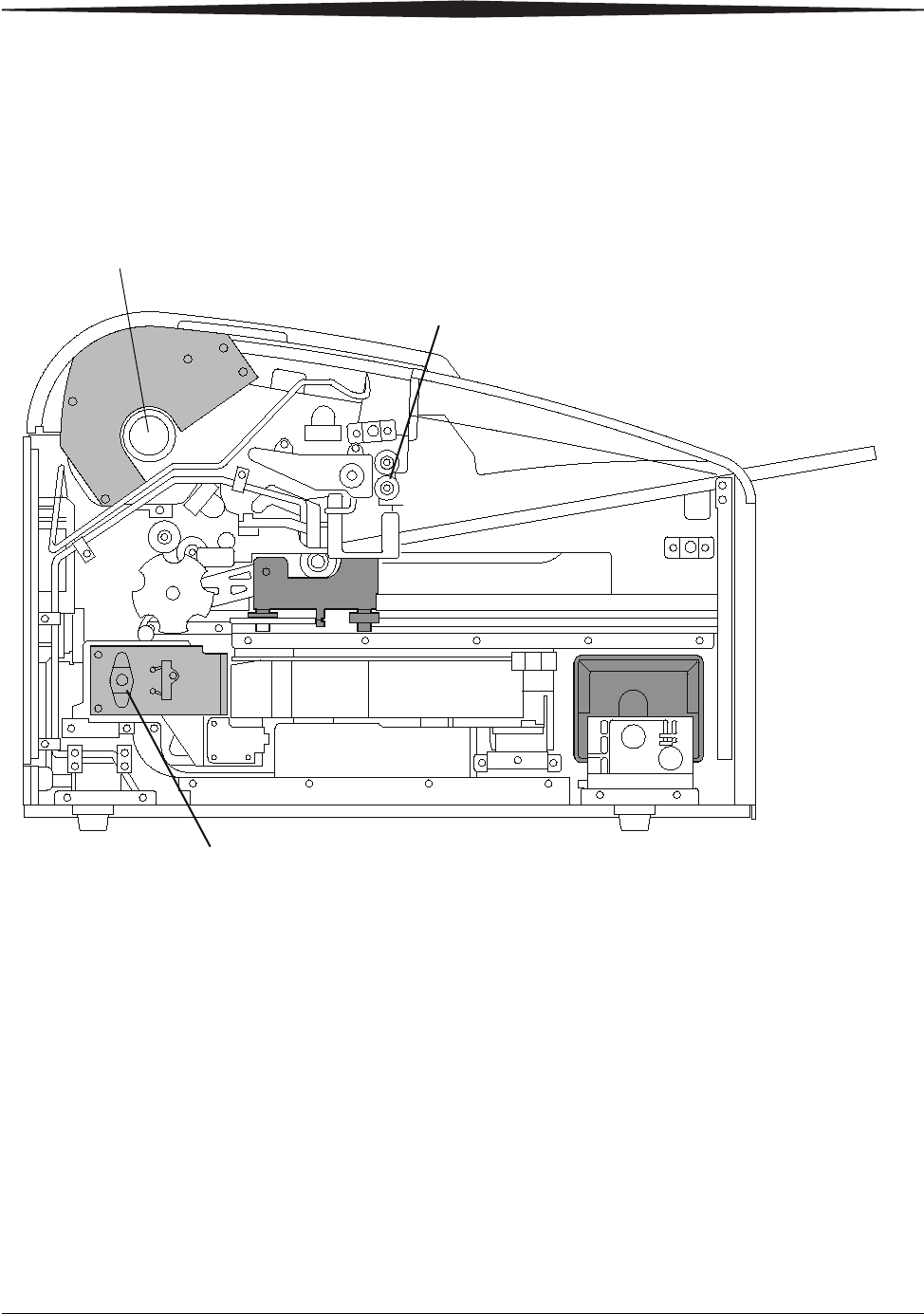
For some jams, you can remove the film by turning a knob to move the
film out of the laser imager. See details in the film jam instructions.
Knobs for manual film removal
Film jam code 116 /
Jam in Area 1 NOTE: This error displays as code 21116 at the Web Portal.
1. If the Pause symbol is on, press it and wait until it goes off.
2. Open the film supply and remove the film cartridge from the laser
imager.
3. Look in Area 1 (the film supply) and remove any film. See
page 3-14 for the film jam areas.
4. Reinsert the film cartridge in the laser imager.
H210_1013HAB
Exit Roller Knob
Exposure Transport Knob
Front of laser imager
Manual rollback knob
3-16 9G3886_en 2011-03-31
Maintenance and Troubleshooting
Film jam code 323 /
Jam in Area 2 NOTE: This error displays as code 26323 at the Web Portal.
1. If the Pause symbol is on, press it and wait until it goes off.
2. Open the film supply.
3. Check that the film cartridge is closed. If it is not closed, carefully
close the cartridge cover.
4. Remove any loose film near, in, or partially in the film cartridge.
5. Close the film supply.
Film jam code 324 or
325 / Jam in Area 2 NOTE: This error displays as code 26324 or 26325 at the Web Portal.
1. If the Pause symbol is on, press it and wait until it goes off.
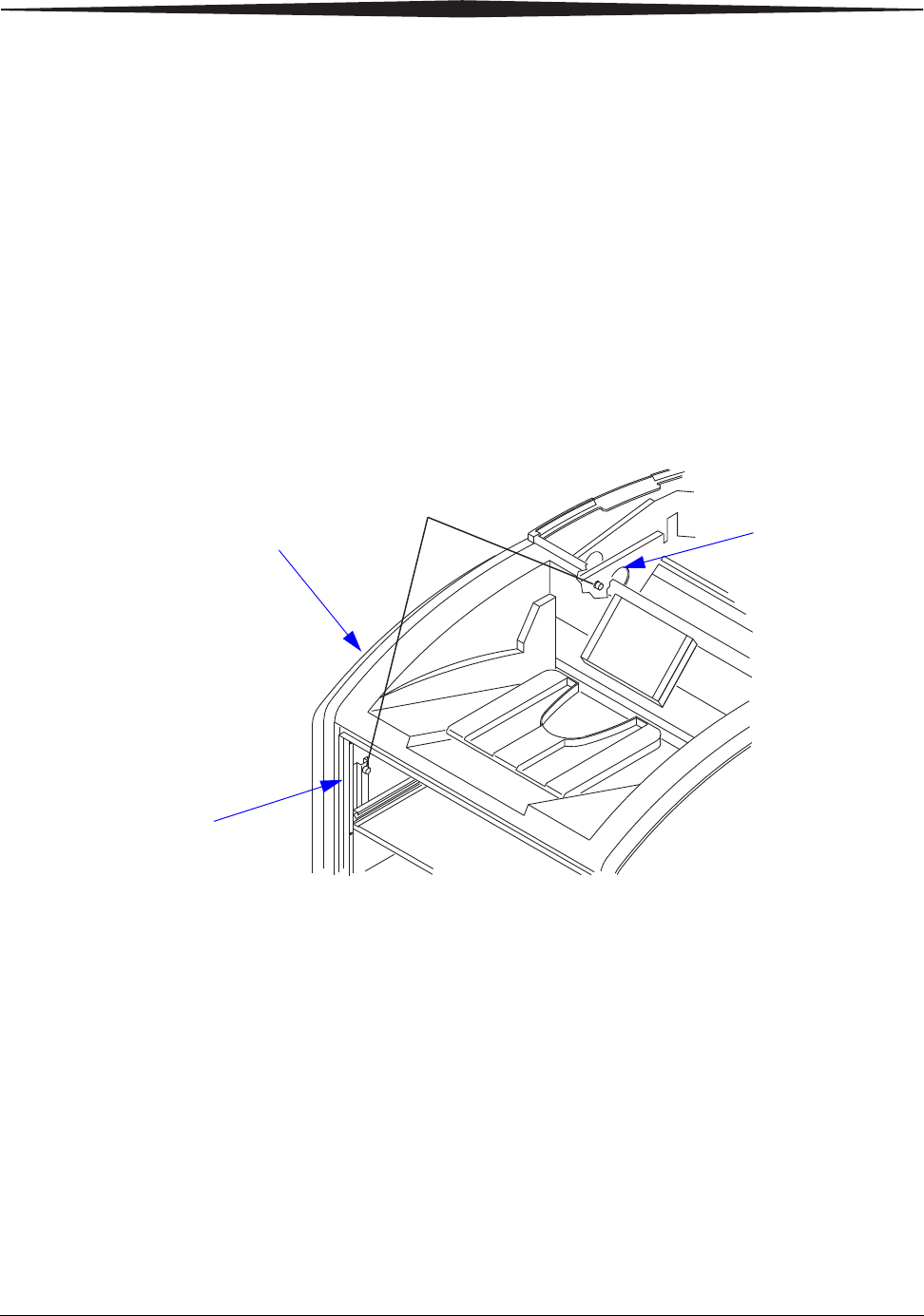
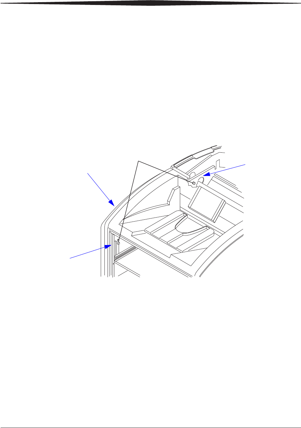
2. Remove the left cover:
a. Open the film supply.
b. Remove the top cover.
c. Turn the knurled knobs by hand.
3. Reach into Area 2 and remove any film. See page 3-14 for the film
jam areas.
4. If the film is not loose, carefully turn the exposure transport knob
clockwise to remove the film from the rollers. See page 3-15 for the
location of the knob.
5. Reinstall the covers.
H210_1017AC
H210_1017ACA
2 Screws
Remove the top
cover to gain
access
Open the film supply
to gain access
Left cover
2 Knurled knobs
Maintenance and Troubleshooting
2011-03-31 9G3886_en 3-17
Film jam code 326 /
Jam in Area 2 or 3 NOTE: This error displays as code 26326 at the Web Portal.
1. If the Pause symbol is on, press it and wait until it goes off.
2. Remove the top cover.
3. Remove the left cover:
a. Open the film supply.
b. Remove the top cover.
c. Turn the knurled knobs by hand.
4. Rotate the exit roller knob clockwise until a film exits the laser
imager. See page 3-15 for the location of the knob.
5. If a film does not exit:
a. Reach into Area 2 and remove any film. See page 3-14 for the
film jam areas.
b. If the film is not loose, carefully turn the exposure transport knob
clockwise to remove the film from the rollers. See page 3-15 for
the location of the knob.
6. Reinstall the covers.
H210_1017AC
H210_1017ACA
2 Screws
Remove the top
cover to gain
access
Open the film supply
to gain access
Left cover
2 Knurled knobs

3-18 9G3886_en 2011-03-31
Maintenance and Troubleshooting
Film jam code 543 /
Jam in Area 3 This error displays as code 26543 at the Web Portal.
1. If the Pause symbol is on, press it and wait until it goes off.
2. Open the top cover.
3. Remove the left cover:
a. Open the film supply.
b. Remove the top cover.
c. Turn the knurled knobs by hand.
4. Rotate the exit roller handle clockwise until a film exits the laser
imager. See page 3-15 for the location of the knob.
5. Reinstall the covers.
Film jam code 544 /
Jam in Area 3 This error displays as code 26544 at the Web Portal.
1. Remove any film that is jammed in the exit tray. See page 3-14 for
the film jam areas.
2. If the Pause symbol is on, press it and wait until it goes off.
3. Open the top cover and remove any films.
4. Close the top cover.
Display Screen is not functional
If the display screen is not responding, use the power switch on the laser
imager to turn power off, and then on. If the display screen is still
non-responsive, turn the laser imager off and contact a qualified service
provider.
Calling for support
If you cannot correct a condition and need help, call for support. Have
the following information ready when you call:
• Model number
• K-number
• Error code from the display screen and/or code and error message
from the Web Portal
Film Technical Information
2011-03-31 9G3886_en 4-1
4
Film Technical Information
General description
This section describes the characteristics of Laser Imaging Film, not the
operation of the laser imager. The Laser Imaging Film is a
high-resolution, infrared-sensitive, photothermographic film designed
specifically for the Laser Imager.
Spectral sensitivity The Laser Imaging Film is infrared sensitive and has been sensitized to
the infrared laser diode of the laser imagers. When handled according to
instructions on the daylight-load film package, safelights are not needed.
If you remove undeveloped film from the daylight-load package, you
will need a darkroom setting and a green safelight.
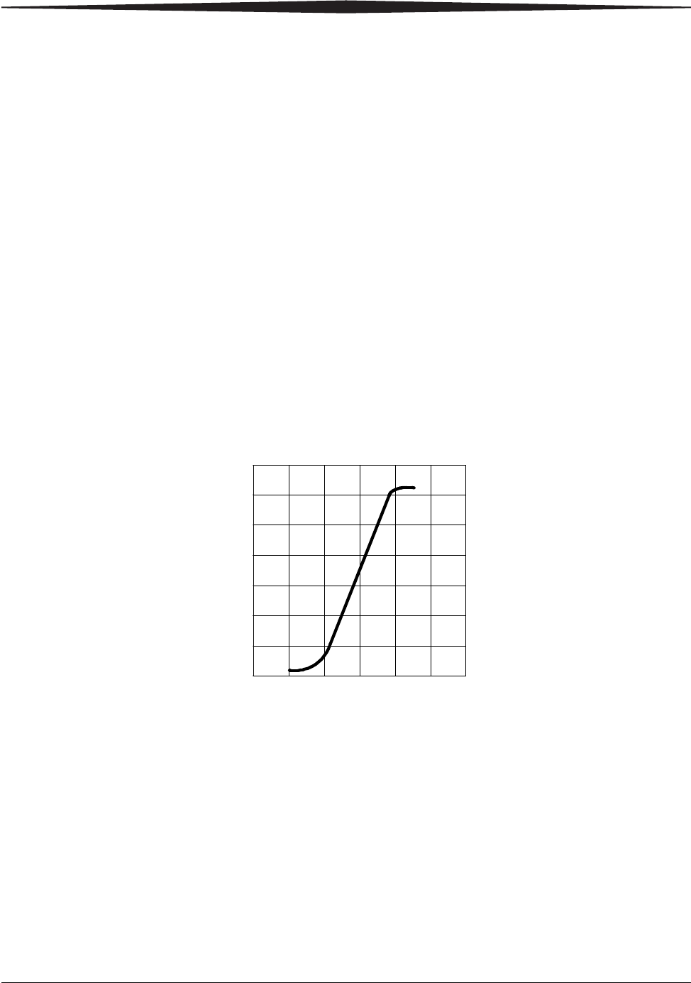
Relative Log Exposure (Example)
Image quality The Laser Imaging Film delivers diagnostic-quality, continuous-tone
images along with sharp alphanumerics and optimum contrast. This
high-quality, silver-based film provides health care providers with the
same diagnostic information they are accustomed to viewing —
including the spatial resolution, contrast, and gray levels. Because it is a
totally dry imaging process, there is no image quality variability due to
wet chemistry.
0 0.5 1 1.5 2 2.5 3
0
0.5
1
1.5
2
2.5
3
3.5
4-2 9G3886_en 2011-03-31
Film Technical Information
Environmental impact Tests show that the Laser Imaging Film is not considered hazardous to
the environment. As a result, you can develop, recycle, and dispose of
film with less impact on the environment than if you were using
wet-developed silver halide films.
Storing and handling
undeveloped film
To achieve consistent results up to the expiration date indicated on the
film package, the Laser Imaging Film must be stored in a cool, dry
place (5° to 25° C, or 41° to 77° F) and protected from radiation and
chemistry fumes.
The film can withstand short-term temperature spikes
(up to 35° C, or 95° F) for several hours during transit without any
significant effect on film quality or performance. Transit temperatures
above 35° C (95° F) will gradually diminish shelf life.
Handling developed film Handling the Laser Imaging Film requires reasonable care. Spills,
humidity, and other moisture typically have no significant effect on
developed films. However, prolonged exposure to intense light or
excessive heat (54.4° C or 130° F) for more than three hours may cause
some gradual darkening of images. Leaving films in vehicles in hot
climates for extended periods of time is not recommended.
For best results, store film in sleeves when not being reviewed. The
Laser Imaging Film can be left on a light box for more than 24 hours. In
extreme cases in which light boxes are exceptionally hot
(49° C, or 120° F), the manufacturer recommends removing them prior
to eight hours of continuous exposure.
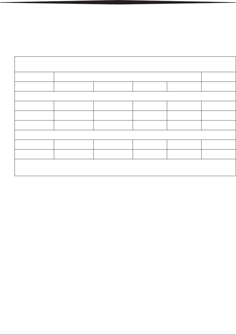
Laser Imaging Film
US Environmental Regulations Comparison
Wet (Silver Halide) Film Dry Film
Developer Fixer Wash Film Film
Product Regulations
OSHA MSDS Required Required Not required Not required Provided
DOT Hazardous Hazardous No limits No limits No limits
Use permits Local Local None None None
Disposal* Regulations
EPA Hazardous Hazardous No No No
DOT Hazardous Hazardous No No No
There is no SUPERFUND liability with dry Laser Imaging Film.
* State and local laws vary. Consult appropriate regulations or authorities prior to disposal.

Film Technical Information
2011-03-31 9G3886_en 4-3
Take care when using spotlight viewing for more than 30 seconds
because temperatures near the light source may exceed 82.2° C
(180° F). Use in slide projectors is not recommended due to the high
temperatures generally found in these devices.
With dry technology, a small amount of final development occurs when
the film exits the laser imager and is initially exposed to ambient or
view-box lighting. This is virtually undetectable and has no effect on
image quality (typically 0.02 change in density). This small density
increase is uniform and permanent upon full exposure of the film under
normal handling conditions (room light or view box).
Archiving developed
film
The Laser Imaging Film has been tested and can be archived for more
than 100 years when stored at American National Standards Institute
(ANSI) recommended storage conditions (25° C or 77° F). Developed
films may be stored at higher temperatures; however, that may reduce
the number of years the film can be stored. For example, storing films at
a constant elevated temperature of 32.2° C (90°F) may reduce archive
capability to 30 years.
Exposing to moisture The Laser Imaging Films typically withstand humidity, spills, and other
forms of water without any significant effect on image quality or film
integrity. If needed, film can be cleaned with a clean, damp cloth.
Dissipating odor Dry technology eliminates virtually all unpleasant odors. While some
low-level odors are produced during the development process, they pose
no known adverse health risks. Processing odor levels are further
reduced by a non-hazardous, recyclable filter in the laser imager. This
filter traps most low-level odors and prevents them from dissipating into
the work environment. To help maintain optimum performance, the
filter requires periodic replacement. The laser imagers require no special
venting.
Dissipating heat The laser imagers use controlled heat to develop the Laser Imaging
Film. The heat has virtually no effect on the air temperature of the work
area. The amount of heat dissipated into an area during a day is typically
less than the heat generated by two to four 100-watt light bulbs.
Recycling film According to the Environmental Protection Agency (EPA) standards, the
Laser Imaging Film is not considered hazardous and requires no special
disposal procedures. However, the film does contain silver and polyester
that may be recovered by using one of several recycling processes.
2011-03-31 9G3886_en 5-1
5
Specifications
Equipment specifications
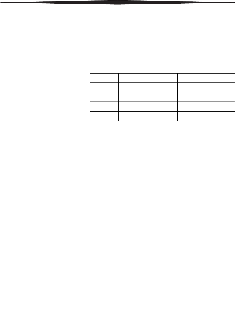
Operating space requirements
Allow 5 cm (2 in.) clearance around the top, sides, and back of the laser
imager. This space is required to let the laser imager perform normal
operator functions. For service functions, allow 15 cm (6 in.) clearance
around the laser imager.
Environmental requirements
Temperature • Operating: 15° to 33° C (59° to 91° F)
• Storage: -40° to 55° C (-40° to 131° F)
Relative humidity • Operating: 20% to 85% RH, noncondensing
• Storage: 10% to 90% RH, noncondensing
Altitude • 30 m (100 ft) below sea level to 3,048 m (10,000 ft) above sea level
Surface levelness • The countertop/floor must be level within 1°.
Environmental effects
• Acoustical Noise:
– Less than 55 dB at 1.5 m during idle or standby
– Less than 75 dB momentary at 1 m during normal operation
Unpacked Packed
Height 47 cm (19 in.) 74 cm (29 in.)
Width 61 cm (24 in.) 79 cm (31 in.)
Depth 66 cm (26 in.) 85 cm (34 in.)
Weight 54 kg (120 lbs) 73 kg (160 lbs)
5-2 9G3886_en 2011-03-31
Specifications
Power requirements
A power cord is provided with this equipment. All countries must use an
Agency-approved power cord with a plug type suitable for the country of
use. Contact a qualified dealer for help.
Connect the equipment to a power source that is suitable for the voltage
and current ratings shown on the rating label. The single-phase power
source, with grounding, must be provided within 2.5 m (8 ft) of the laser
imager.
The wire must be insulation-rated for 600 V (ac). A dedicated line is
recommended.
Network requirements
The laser imager receives digital images from medical imaging devices
(modalities) over a 10/100Base-T or 1000Base-T Ethernet Network.
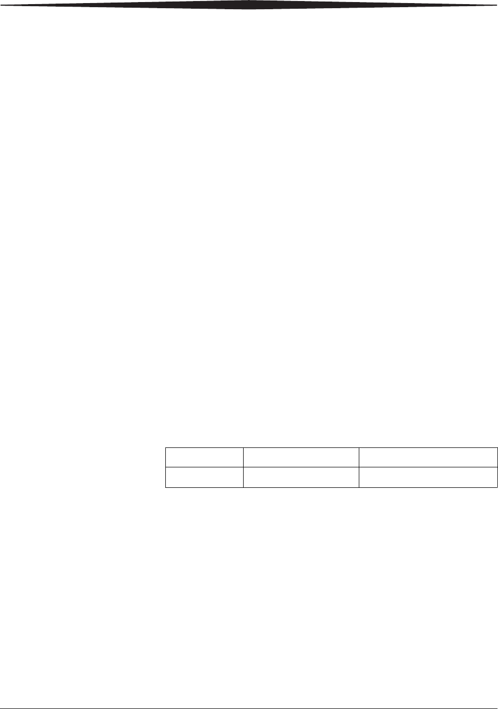
Publication History
Revision Date Reason for Change
A2011-03-31 First release