Carestream Health DRX1 THE DRX-1 RADIO IS A LOW POWER UNII DEVICE OPERATING AS AN 802.11n STATION IN A LAN. User Manual urg 00870
Carestream Health, Inc. THE DRX-1 RADIO IS A LOW POWER UNII DEVICE OPERATING AS AN 802.11n STATION IN A LAN. urg 00870
Users Manual
CARESTREAM DRX-1 System
Safety and Regulatory Information
with
Hardware
User’s Guide
Version 2.0
PN 7H8166
22 January 2009
CarestreamCarestream DRX1 System
H224_0028HC

7H8166 1
Table of Contents
1 Safety and Regulatory Information
Document Conventions ....................................................................................................................................1-1
Intended Use and Indications for Use...............................................................................................................1-1
Safety and Related Information.........................................................................................................................1-2
Medical Equipment Classification...............................................................................................................1-2
Compatibility with Other Manufacturer’s Equipment ..................................................................................1-3
Product Safety Standards............................................................................................................................1-4
EMC Standards for Detector and System.....................................................................................................1-7
Safety .........................................................................................................................................................1-7
Additional Guidance and Manufacturer’s Declaration - Electromagnetic Emissions/Immunity....................1-7
Electromagnetic Compatibility Precautions...........................................................................................1-7
Communications Equipment ................................................................................................................1-8
Replacement of Cables, Accessories, or Transducers ...........................................................................1-8
Other Equipment..................................................................................................................................1-8
Shielded Locations ...............................................................................................................................1-8
DRX-1 System Product Information................................................................................................................1-13
DRX-1 System Detector ............................................................................................................................1-13
DRX-1 System Battery Charger..................................................................................................................1-14
DRX-1 System Battery...............................................................................................................................1-15
DRX-1 System Console .............................................................................................................................1-15
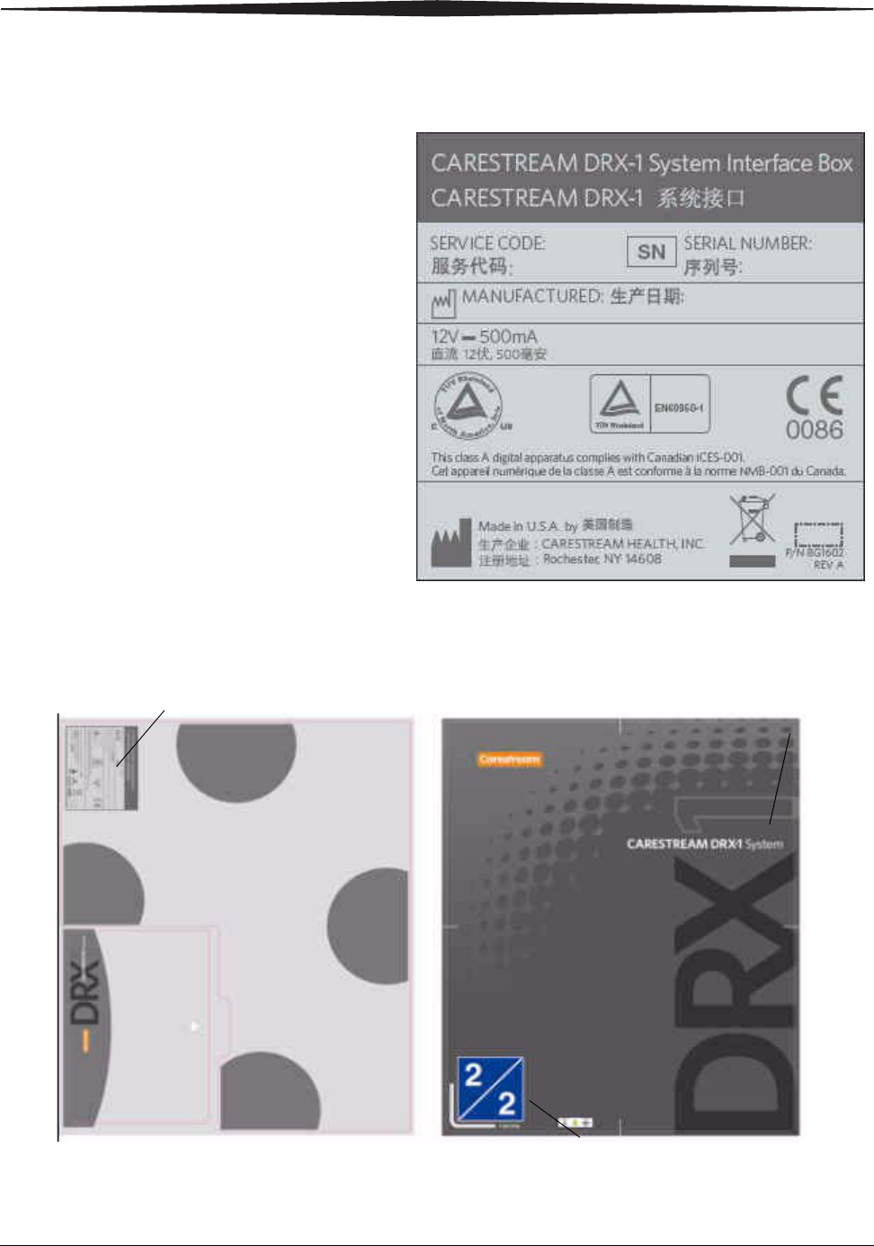
DRX-1 System Interface Box (Internal) ....................................................................................................1-16
DRX-1 System Wireless Access Point ........................................................................................................1-16
DRX-1 System Tether Interface.................................................................................................................1-16
Patient Vicinity .........................................................................................................................................1-17
Mode of Operation...................................................................................................................................1-17
Labels ......................................................................................................................................................1-18
Disposal Information .....................................................................................................................................1-23
Operating Environment ..................................................................................................................................1-23
For European Market Only.......................................................................................................................1-23
General Contact Information ....................................................................................................................1-23
2 Hardware and Operation
Overview ..........................................................................................................................................................2-1

2 7H8166
Table of Contents
CARESTREAM DRX-1 System ............................................................................................................................2-2
Cautions...........................................................................................................................................................2-3
Installing the Hardware....................................................................................................................................2-3
Attaching Accessories.................................................................................................................................2-4
Turning the System On and Off...................................................................................................................2-4
CARESTREAM DRX-1 System Battery.................................................................................................................2-5
Installing the Battery ..................................................................................................................................2-5
Removing the Battery .................................................................................................................................2-6
Labeling the Detector .......................................................................................................................................2-6
DRX-1 Detector LED.........................................................................................................................................2-7
Positioning the Detector in the Bucky...............................................................................................................2-8
Range of Operation ........................................................................................................................................2-10
Using a Single Detector ............................................................................................................................2-10
Using Two or More Detectors...................................................................................................................2-10
Using Detectors in Two or More Rooms...................................................................................................2-11
Wireless Operation.........................................................................................................................................2-11
Tether Operation............................................................................................................................................2-12
Tether Interface Box ................................................................................................................................2-13
Cleaning the Hardware...................................................................................................................................2-13
With Each Occurrence of Patient Contact .......................................................................................................2-14
System Maintenance.......................................................................................................................................2-15
Checking the Equipment Integrity.............................................................................................................2-16
Grid Recommendation .............................................................................................................................2-16
Protective Enclosures...............................................................................................................................2-16

7H8166 1-1
1
Safety and Regulatory
Information
The information contained herein is based on the experience and knowledge
relating to the subject matter gained by Carestream Health, Inc. prior to
publication.
No patent license is granted by this information.
Carestream Health reserves the right to change this information without
notice, and makes no warranty, express or implied, with respect to this
information. Carestream Health shall not be liable for any loss or damage,
including consequential or special damages, resulting from any use of this
information, even if loss or damage is caused by Carestream Health’s
negligence or other fault.
Document Conventions
NOTE: Notes provide additional information, such as expanded
explanations, hints, or reminders.
IMPORTANT: Important highlights critical policy information that
affects how you use this manual and this product
CAUTION:
Caution points out procedures that you must follow precisely
to avoid damage to the system or any of its components,
yourself or others, loss of data, or corruption of files in
software applications.
Intended Use and Indications for Use
The CARESTREAM DRX-1 System is intended to capture for display
radiographic images of human anatomy. It is intended for use in general
projection radiographic applications wherever conventional screen-film or
Computed Radiography (CR)systems may be used. Excluded from the
indications for use are mammography, fluoroscopy., tomography, and
angiography applications.

1-2 7H8166
Safety and Regulatory Information
Safety and Related Information
Medical Equipment
Classification
CARESTREAM DRX-1 System Detector Medical Electrical
Equipment Classification
Type of protection against electrical shock: Internally powered equipment. Class I
Equipment.
Degree of protection against electrical
shock:
Type B Applied Part.
Degree of protection against ingress of wa-
ter:
Ordinary protection.
Mode of operation: Continuous operation.
Flammable anesthetics: Not suitable for use in the presence of flam-
mable anesthetics or a mixture of flamma-
ble anesthetics with air or oxygen or
nitrous oxide.
CARESTREAM DRX-1 System Tether Interface Medical Electrical
Equipment Classification
Type of protection against electrical shock: Class I Equipment.
Degree of protection against electrical
shock:
Type B.
Degree of protection against ingress of wa-
ter:
Ordinary protection.
Mode of operation: Continuous operation.
Flammable anesthetics: Not suitable for use in the presence of flam-
mable anesthetics or a mixture of flamma-
ble anesthetics with air or oxygen or
nitrous oxide.
Safety and Regulatory Information
7H8166 1-3
• The CARESTREAM DRX-1 System includes the following components:
CARESTREAM DRX-1 System Detector (one or more)
CARESTREAM DRX-1 System Battery (any quantity)
CARESTREAM DRX-1 System Battery Charger
CARESTREAM DRX-1 System Tether Interface
CARESTREAM DRX-1 System Console
CARESTREAM DRX-1 System Access Point
Compatibility with
Other Manufacturer’s
Equipment
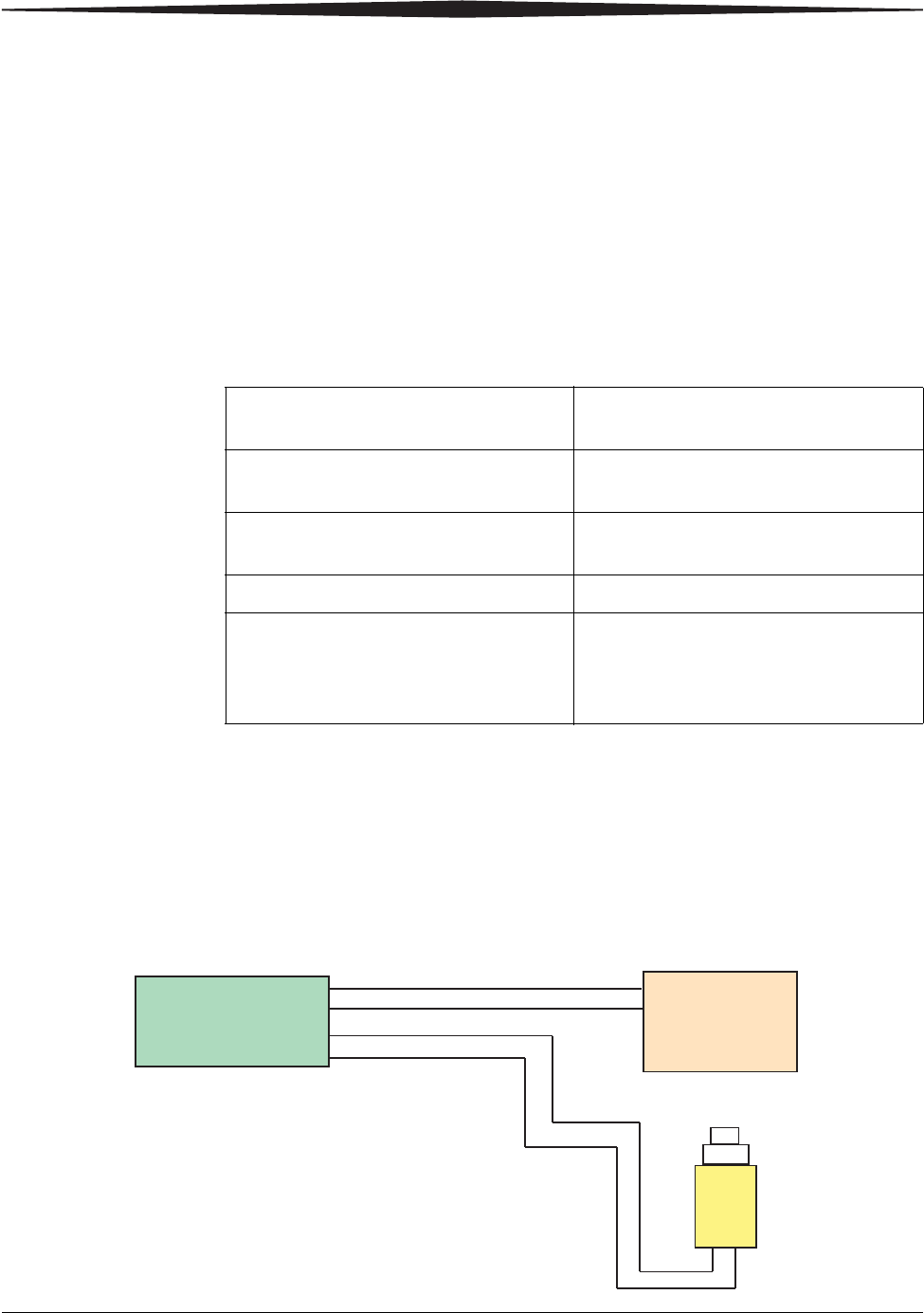
The CARESTREAM DRX-1 System (DRX-1 System) is a digital X-ray image
capture system. The DRX-1 System connects with existing analog x-ray
equipment using a safety certified electrical isolation device (DRX-1 System
Interface Box). The isolation device is designed to prevent any failures, loss of
power or power surge in the DRX-1 System from affecting the X-ray
equipment.
CARESTREAM DRX-1 System Medical Electrical Equipment
Classification
Type of protection against electrical shock: Internally powered equipment. Class I
Equipment.
Degree of protection against electrical
shock:
Type B Applied Part.
Degree of protection against ingress of wa-
ter:
Ordinary protection.
Mode of operation: Continuous operation.
Flammable anesthetics: Not suitable for use in the presence of flam-
mable anesthetics or a mixture of flamma-
ble anesthetics with air or oxygen or
nitrous oxide.
H224_9001BA
Prep Start
Prep Request
Expose Request
X-ray Console
Input
Exposure
Switch
Expose Start
Box
Interface
DRX-1 System
Output

1-4 7H8166
Safety and Regulatory Information
The DRX-1 System uses an existing exposure switch connector on the X-ray
equipment. No modification to the X-ray equipment is required. The intended
use of the X-ray equipment is not affected and the X-ray equipment remains
certified by the X-ray equipment manufacturer.
Model-specific documentation and cables are provided to allow service
personnel to connect and run functional testing on the DRX-1 System. The
DRX-1 System is compatible with the X-ray equipment listed on the Certificate
of Compatibility available from your local authorized service provider. Contact
your local authorized service provider for further information.
Product Safety
Standards
The following Product Safety Standards are applicable to:
• CARESTREAM DRX-1 System Detector
• CARESTREAM DRX-1 System Tether Interface
The following Product Safety Standards are applicable to:
• CARESTREAM DRX-1 System. The DRX-1 System includes the following
components:
CARESTREAM DRX-1 System Detector (one or more)
CARESTREAM DRX-1 System Battery (any quantity)
USA UL 60601-1:2003 - Medical Electrical Equipment
Canada CAN/CSA-C22.2 No. 601.1-M90 (R2001) Medical Electrical Equipment
CAN/CSA-C22.2 No. 601.1S1-94 (R1999) - Supplement No. 1-94 to
CAN/CSA-C22.2 No. 601.1-M90
CAN/CSA-C22.2 No. 601.1B-90 (R2002) - Amendment 2 to CAN/CSA-C22.2
No. 601.1-M90
Europe EN 60601-1:1990 + Amendment 1:1993 + Amendment 2:1995 - Medical
Electrical Equipment
EN 60601-1-1:2001 - Medical Electrical Systems
EN 60601-1-4:1996 + Amendment 1:1999 - Programmable Electrical
Medical Systems
International IEC 60601-1:1988 + Amendment 1:1991 + Amendment 2:1995 - Medical
Electrical Equipment
IEC 60601-1-1:2000 - Medical Electrical Systems
IEC 60601-1-4:1996 + Amendment 1:1999 - Programmable Electrical
Medical Systems

Safety and Regulatory Information
7H8166 1-5
CARESTREAM DRX-1 System Battery Charger
CARESTREAM DRX-1 System Tether Interface
CARESTREAM DRX-1 System Console
CARESTREAM DRX-1 System Wireless Access Point
USA UL 60601-1:2003 - Medical Electrical Equipment, 1st Edition
Canada CAN/CSA-C22.2 No. 601.1-M90 (R2001) Medical Electrical Equipment
CAN/CSA-C22.2 No. 601.1S1-94 (R1999) - Supplement No. 1-94 to
CAN/CSA-C22.2 No. 601.1-M90
CAN/CSA-C22.2 No. 601.1B-90 (R2002) - Amendment 2 to CAN/CSA-C22.2
No. 601.1-M90
Europe EN 60601-1:1990 + Amendment 1:1993 + Amendment 2:1995 - Medical
Electrical Equipment
EN 60601-1-1:2001 - Medical Electrical Systems
EN 60601-1-4:1996 + Amendment 1:1999 - Programmable Electrical
Medical Systems
International IEC 60601-1:1998 + Amendment 1:1991 + Amendment 2:1995 - Medical
Electrical Equipment
IEC 60601-1-1:2000 - Medical Electrical Systems
IEC 60601-1-4:1996 + Amendment 1:1999 - Programmable Electrical
Medical Systems

1-6 7H8166
Safety and Regulatory Information
The following Product Safety Standards are applicable to:
• CARESTREAM DRX-1 System Battery
The following Product Safety Standards are applicable to:
• CARESTREAM DRX-1 System Battery Charger
• CARESTREAM DRX-1 System Console
• CARESTREAM DRX-1 System Wireless Access Point
USA UL 60601-1:2003 - Medical Electrical Equipment, 1st Edition
Canada CAN/CSA-C22.2 No. 601.1-M90 (R2001) Medical Electrical Equipment
CAN/CSA-C22.2 No. 601.1S1-94 (R1999) - Supplement No. 1-94 to
CAN/CSA-C22.2 No. 601.1-M90
CAN/CSA-C22.2 No. 601.1B-90 (R2002) - Amendment 2 to CAN/CSA-C22.2
No. 601.1-M90
Europe EN 60601-1:1990 + Amendment 1:1993 + Amendment 2:1995 - Medical
Electrical Equipment
International IEC 60601-1:1988 + Amendment 1:1991 + Amendment 2:1995 - Medical
Electrical Equipment
USA UL 60950-1, Information Technology Equipment - Safety - Part 1: General
Requirements
Canada CAN/CSA C22.2 No. 60950-1-03, Information Technology Equipment - Safety
- Part 1: General Requirements
Europe EN 60950-1:2001 + A11, Information Technology Equipment - Safety - Part
1: General Requirements
International IEC 60950-1:2001, Information Technology Equipment - Safety - Part 1:
General Requirements

Safety and Regulatory Information
7H8166 1-7
EMC Standards for
Detector and System
IEC 60601-1-2:2004 EMC requirements and tests, Medical Electrical
Equipment including CISPR 11:1999+A2:02, Group 1, Class A.
This device complies with part 15 of the FCC Rules. Operation is subject to the
following two conditions:
1. This device may not cause harmful interference.
2. This device must accept any interference received, including interference
that may cause undesired operation.
This equipment has been tested and found to comply with the limits for a Class
A digital device, pursuant to part 15 of the FCC Rules. These limits are
designed to provide reasonable protection against harmful interference when
the equipment is operated in a commercial environment. This equipment
generates, uses and can radiate radio frequency energy and, if not installed
and used in accordance with the instruction manual, may cause harmful
interference to radio communications. Operation of this equipment in a
residential area is likely to cause harmful interference in which case the users
will be required to correct the interference at their own expense.
Changes or modifications not expressly approved by the manufacturer could
void the user’s authority to operate the equipment.
CAUTION:
This is a Class A product. In a domestic environment this
product may cause radio interference, in which case the user
may be required to take adequate measures.
NOTE: For CARESTREAM DRX-1 System Battery Charger or Battery EMC
information and instruction for use, see the CARESTREAM DRX-1
System Battery Charger User’s Guide.
Safety This product complies with 21 CFR 1020.30/31 Performance Standards for
Radiation Safety - Radiographic Equipment.
Additional Guidance
and Manufacturer’s
Declaration -
Electromagnetic
Emissions/Immunity
Electromagnetic
Compatibility Precautions
Medical electrical equipment requires special precautions regarding
electromagnetic compatibility (EMC). Medical equipment must be installed
and put into service according to the EMC information provided in the
following documentation.

1-8 7H8166
Safety and Regulatory Information
Communications
Equipment
Portable and mobile radio frequency (RF) communications equipment can
affect medical electrical equipment EMC performance.
The wireless version of the Carestream DRX-1 System Detector operates with
the 802.11n protocol in the 5 GHz frequency band. The radio output power is
50 mW (nominal).
CAUTION:
Replacement of Cables,
Accessories, or
Transducers
The use of cables, accessories or transducers other than those specified
below with the exception of transducers or cables sold by the manufacturer of
the equipment as replacement parts for internal components, may result in
increased emissions or decreased immunity of the medical equipment.
Other Equipment The CARESTREAM DRX-1 System should not be used adjacent to or stacked
with other equipment. If adjacent or stacked use is necessary, the Carestream
DRX-1 System should be observed to verify normal operation in the
configuration in which it will be used.
Cable, Accessory and Transducer Information for the Carestream DRX-1
System will be available prior to production release of the product.
Shielded Locations The typical location of the CARESTREAM DRX-1 System will be in a shielded
room only because the system functions with sources of X-Ray energy. The
CARESTREAM DRX-1 System is fully compliant with the requirements of IEC
60601-1-2:2004 without being located in a shielded room.

Safety and Regulatory Information
7H8166 1-9
Guidance and Manufacturer’s Declaration - Electromagnetic Emissions
The CARESTREAM DRX-1 System is intended for use in the electromagnetic environment specified
below. The customer or the user of the CARESTREAM DRX-1 System should assure that it is used in
such an environment.
Emissions Test Compliance Electromagnetic Environment - Guidance
RF Emissions
CISPR 11
Group 1 The CARESTREAM DRX-1 System uses RF energy only for its
internal function. Therefore, its RF emissions are very low
and are not likely to cause any interference in nearby
electronic equipment.
RF Emissions
CISPR 11
Class A The CARESTREAM DRX-1 System is suitable for use in all
establishments other than domestic and those directly
connected to the public low-voltage power supply network
that supplies buildings used for domestic purposes.
Harmonics
Emissions
IEC 61000-3-2
Class A
Voltage
Fluctuations/
Flicker Emissions
IEC 61000-3-3
Complies

1-10 7H8166
Safety and Regulatory Information
NOTE: UT is the a.c. mains voltage prior to application of the test level.
Electromagnetic Immunity for Equipment and Systems Fully Compliant with IEC
60601-1-2:2004
The CARESTREAM DRX-1 System is intended for use in the electromagnetic environment specified below. The
customer or the user of the CARESTREAM DRX-1 System should assure that it is used in such an environment.
Immunity Test IEC 60601
Test Level
Compliance
Level
Electromagnetic Environment-
Guidance
Electrostatic Discharge
(ESD)
IEC 61000-4-2
+/- 6 kV contact
+/- 8 kV air
+/- 6 kV contact
+/- 8 kV air
Floors should be wood, concrete or
ceramic tile. If floors are covered with
synthetic material, the relative humidity
should be at least 30%.
Electrical fast
transient/burst
IEC 61000-4-4
+/- 2 kV for
power supply
lines
+/- 1 kV for
input/output
lines
+/- 2 kV for
power supply
lines
+/- 1 kV for
input/output
lines
Mains power quality should be that of a
typical commercial or hospital
environment.
Surge
IEC 61000-4-5
+/- 1 kV line to
line
+/- 2 kV line to
earth
+/- 1 kV line to
line
+/- 2 kV line to
earth
Mains power quality should be that of a
typical commercial or hospital environment
Voltage dips, short
interruptions and voltage
variations on power supply
lines
IEC 61000-4-11
<5% UT (>95%
dip in UT) for
0.5 cycle
40% UT (60%
dip in UT) for 5
cycles
70% UT (30%
dip in UT) for25
cycles
<5% UT (>95%
dip in UT) for 5
sec.
<5% UT (>95%
dip in UT) for
0.5 cycle
40% UT (60%
dip in UT) for 5
cycles
70% UT (30%
dip in UT) for25
cycles
<5% UT (>95%
dip in UT) for 5
sec.
Mains power quality should be that of a
typical commercial or hospital
environment.
Note: Most components in the
CARESTREAM DRX-1 System are powered
from an uninterruptible power supply.
IEC 61000-4-11 is applicable only to the
CARESTREAM DRX-1 System tether
Interface.
Power frequency
(50/60Hz)magnetic field
IEC 61000-4-8
3 A/m 3 A/m Power frequency magnetic fields should be
at levels characteristic of a typical location
in a typical commercial or hospital
environment.
Safety and Regulatory Information
7H8166 1-11
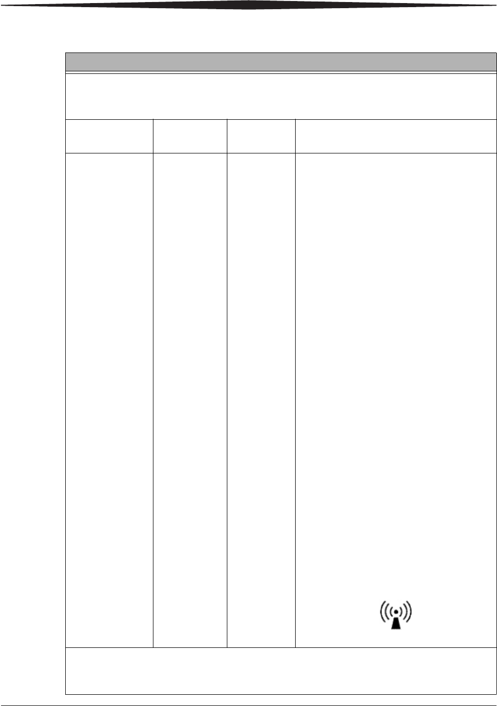
Guidance and Manufacturer’s Declaration - Electromagnetic Immunity
The CARESTREAM DRX-1 System is intended for use in the electromagnetic environment specified
below. The customer or the user of the CARESTREAM DRX-1 System should assure that it is used in
such an environment.
Immunity Test IEC 60601
Test Level
Compliance
Level
Electromagnetic Environment - Guidance
Conducted RF
IEC 61000-4-6
Radiated RF
IEC 61000-4-3
3 Vrms
150 kHz to 80
MHz
3 v/m
80 MHz to
2.5GHz
3 Vrms
3 v/m
Portable and mobile RF communications
equipment should be used no closer to any
part of the CARESTREAM DRX-1 System,
including cables, than the recommended
separation distance calculated from the
equation applicable to the frequency of the
transmitter.
Recommended separation distance
d = 1.17 √P
d = 1.17 √P 80 MHz to 800 MHz
d = 2.33 √P 800MHz to 2.5GHz
where P is the maximum output rating of the
transmitter in watts (W) according to the
transmitter manufacture and d is
recommended separation distance in meters
(m).
Field strengths from fixed RF transmitters, as
determined by an electromagnetic site surveya,
should be less than the compliance level in
each frequency rangeb.
Interference may occur in the vicinity of
equipment marked with the following symbol:
NOTE 1 At 80 MHz and 800 MHz, the higher frequency range applies.
NOTE 2 These guidelines may not apply in all situations. Electromagnetic propagation is affected by absorption and
reflection from structures, objects and people.
1-12 7H8166
Safety and Regulatory Information
a Field strengths from fixed transmitters, such as base station for radio (cellular/cordless) telephones and land mobile
radios, amateur radio, AM and FM radio broadcast and TV broadcast cannot be predicted theoretically with accuracy. To
assess the electromagnetic environment due to fixed RF transmitters, an electromagnetic site survey should be considered.
If the measured field strength in the location in which the CARESTREAM DRX-1 System is used exceeds the applicable RF
compliance level above, the CARESTREAM DRX-1 System should be observed to verify normal operation. If abnormal
performance is observed, additional measures may be necessary, such as reorienting or relocating the CARESTREAM
DRX-1 System.
b Over the frequency range 150 kHz to 80 MHz, field strengths should be less than 3 v/m.
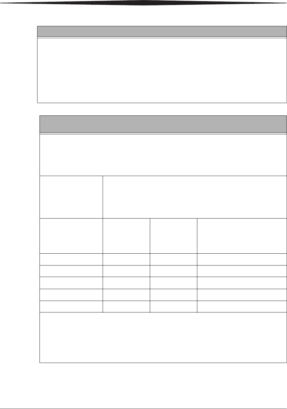
Recommended Separation Distance Between Portable and Mobile RF
Communications Equipment and the CARESTREAM DRX-1 System
The CARESTREAM DRX-1 System is intended for use in an electromagnetic environment in which
radiated RF disturbances are controlled. The customer or the user of the CARESTREAM DRX-1 System
can help prevent electromagnetic interference by maintaining a minimum distance between portable
and mobile RF communication equipment (transmitters) and the CARESTREAM DRX-1 System as
recommended below, according to the maximum output of the communications equipment.
Rated Maximum
Output Power of
Transmitter
Watts
Separation Distance According to Frequency of Transmitter
Meters
150 kHz to 80
MHz
d = 1.17 √P
80 MHz to 800
MHz
d = 1.17 √P
800 MHz to 2.5 GHz
d = 2.33 √P
0.01 0.117 0.117 0.233
0.1 0.37 0.37 0.737
1 1.17 1.17 2.33
10 3.7 3.7 7.36
100 11.7 11.7 23.3
For transmitters rated at a maximum output power not listed above, the recommended separation distance d in meters
(m) can be estimated using the equation applicable to the frequency of the transmitter, where P is the maximum output
power rating of the transmitter in watts (W) according to the transmitter manufacturer.
NOTE 1 At 80 MHz and 800 MHz, the separation distance for the higher frequency range applies.
NOTE 2 These guidelines may not apply in all situations. Electromagnetic propagation is affected by absorption and
reflection from structures, objects and people.
Guidance and Manufacturer’s Declaration - Electromagnetic Immunity
Safety and Regulatory Information
7H8166 1-13
DRX-1 System Product Information
DRX-1 System
Detector
CARESTREAM DRX-1 System Detector
NOTE: For Computer, CARESTREAM DRX-1 System Battery Charger, and
CARESTREAM DRX-1 System Battery regulatory information and
instruction for use, see the manufacturer’s User Guide.
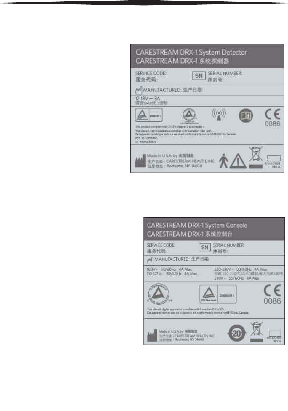
Detector Size 38 x 46 x 1.6 cm
Detector Image Area 35 x 43 cm
Detector Weight 4 kg (8.5 lb.)
Detector Weight-Ap-
plied Limit
Applied to a single 5 cm (2 in.) point: 23 kg
(50 lb.)
Distributed evenly over the detector area: 125 kg
(275 lb.)
Electrical Ratings 12-18V DC, 3A
1-14 7H8166
Safety and Regulatory Information
DRX-1 System Battery
Charger
NOTE: For complete information on the CARESTREAM DRX-1 System Battery
Charger, see the CARESTREAM DRX-1 Battery Charger User’s Guide.
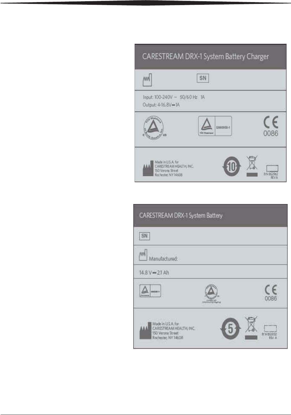
CARESTREAM DRX-1 System Battery Charger
Size 38 x 14 x 18 cm
Weight 2.26 kg (5 lb.)
Electrical Ratings 100-240VAC, 50/60 Hz, 1.0A
Power Output: 12 V to 16.8 V, Constant Current/Constant
Voltage, Lithium Ion charge method, 1A
max charge current.
Carestream
Carestream
H223_0004BA
Carestream SystemDRX1
Carestream SystemDRX1
Safety and Regulatory Information
7H8166 1-15
DRX-1 System Battery NOTE: For complete information on the care and handling of the DRX-1
System Battery, see the CARESTREAM DRX-1 System Battery User’s
Guide.
CAUTION:
The System console is not medical electrical equipment and
should not be placed in the patient vicinity.
See “Patient Vicinity” on page 1-17.
DRX-1 System Console
CARESTREAM DRX-1 System Console
Size 21 x 15 x 0.5 cm
Weight 0.4 kg (12.4 oz.)
Electrical Ratings 14.8V DC, 2.1Ah (nominal) capacity
Size 57 x 50 x 28 cm
Weight 41 kg (90 lb.)
Electrical Ratings 100V ac, 50/60 Hz, 4A; 100-127 V ac, 60
Hz, 4.0A; 220-240V ac, 50/60 Hz, 4A
H223_0005HA
Carestream
Carestream SystemDRX1

1-16 7H8166
Safety and Regulatory Information
DRX-1 System
Interface Box
(Internal)
DRX-1 System
Wireless Access Point
DRX-1 System Tether
Interface
NOTE: For Computer, CARESTREAM DRX-1 System Battery Charger, and
CARESTREAM DRX-1 System Battery regulatory information and
instruction for use, see the CARESTREAM DRX-1 System Battery
Charger User’s Guide and the CARESTREAM DRX-1 System Battery
User’s Guide.
Size 13 x 18 x 8 cm
Weight 0.45 kg (1 lb.)
Electrical Ratings 12V DC, 0.5A
See CISCO Wireless Access Point User Guide for Specifications.
Electrical Ratings 100-240V AC
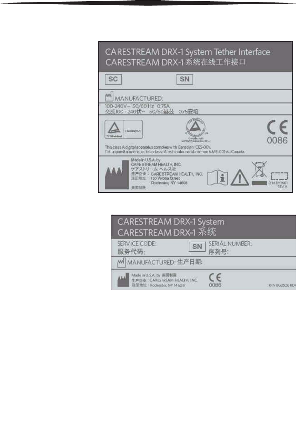
Size 16 x 24 x 7 cm
Weight 02.3 kg (5 lb.)
Electrical Ratings 100-240V AC, 0.75A
Safety and Regulatory Information
7H8166 1-17
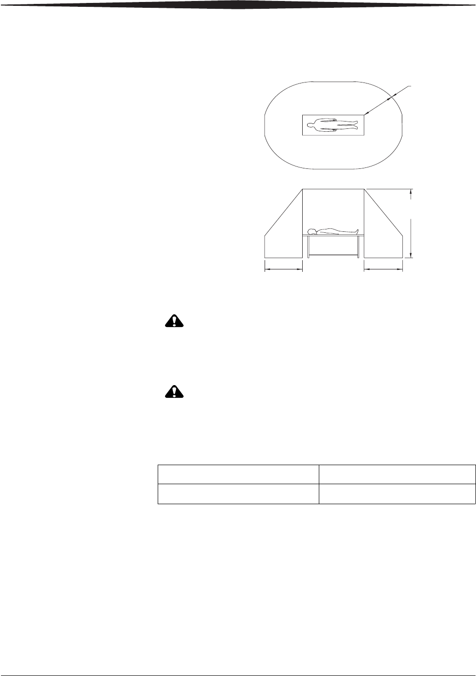
Patient Vicinity
CAUTION:
The System Console, Battery Charger, and Wireless Access Point
are not medical electrical equipment and should not be placed
in the patient vicinity.
CAUTION:
Keep all electronic devices (wireless or hardwired) three feet
from the detector when in use.
Mode of Operation
H196_0004GC
1.83 m
2.5 m
1.83 m
1.83 m
(6 ft)(6 ft)
(6 ft)
(8 ft)
DRX-1 Detector Continuous
DRX-1 System Tether Interface Continuous
1-18 7H8166
Safety and Regulatory Information
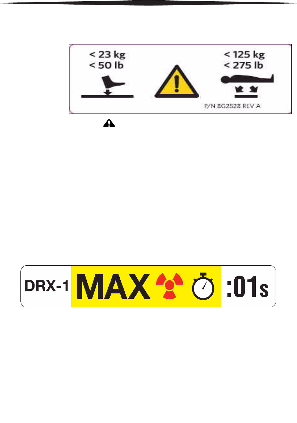
Labels Detector Weight Limit Label
CAUTION:
Since the detector is not a patient support device, it must be
placed on a suitable surface such as a table or floor before
applying patient weight to it. The weight label indicates
acceptable limits of use that will not damage the detector. To
prolong the life of the detector, and minimize potential
internal detector damage, observe the following weight
restrictions:
• The maximum concentrated weight over a small area of the detector
surface (50 mm diameter) must not exceed 23 kg (50 lb.).
• The maximum distributed weight applied uniformly over the entire
detector surface is 125 Kg (275 lb.).
Maximum Exposure Time Label
This label indicates a requirement of one-second maximum exposure
time for the DRX-1 System Detector. This label should be adhered close
to the Console or on the DRX-1 System Monitor so that it is readily seen.
The label means:CAUTION: MAXIMUM EXPOSURE TIME IS ONE SECOND.
Safety and Regulatory Information
7H8166 1-19
Battery Charger Dataplate Label
DRX-1 Battery Dataplate Label
1-20 7H8166
Safety and Regulatory Information
DRX-1 System Detector Dataplate Label
System Console Label
Safety and Regulatory Information
7H8166 1-21
System Tether Interface
System Label
1-22 7H8166
Safety and Regulatory Information
System Interface Box
Detector Labeling
Battery
Identification Label
Dataplate Label
Safety and Regulatory Information
7H8166 1-23
Disposal Information
In the European Union, this symbol indicates that when th
e
last user wishes to discard this product, it must be sent to
appropriate facilities for recovery and recycling. Contact
your local representative or refer to
http://recycle.carestreamhealth.com for additional
information on the collection and recovery programs
available for this product.
NOTE: For disposal information for the CARESTREAM DRX-1 System Battery
Charger or CARESTREAMDRX-1 System Battery see the CARESTREAM
DRX-1 System Battery Charger User’s Guide or the CARESTREAM
DRX-1 System Battery User’s Guide.
Operating Environment
CAUTION:
Do not operate this equipment outside of its operating
environment limits. Doing this may cause the equipment to
malfunction. The operating environment limits are as follows:
For European Market
Only
Authorized European Agent:
Carestream Health France
LES MERCURIALES
40, rue Jean Jaures
93176 BAGNOLET CEDEX
France
General Contact
Information
Carestream Health, Inc.
150 Verona Street
Rochester, New York 14608
System Environmental 10-30°C, 10-86% RH, maximum altitude
3048 meters, 70-106kPa
Battery Charger Environmental Operating: 0° C to 30° C (32° F to 86° F)
Storage: -20° C to 70° C (-4° F to 158° F)

7H8166 2-1
2
Hardware and Operation
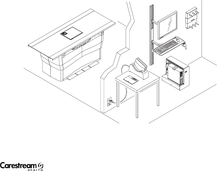
Overview
The CARESTREAM DRX-1 System lets you connect a digital DR Detector to an
analog system and capture images digitally. Use the existing analog console to
set up the exam and determine the technique. Then, expose the subject with
the DRX -1 System and view and manipulate the image on the computer using
Image Viewing Acquisition Software. You can send the image to destinations
such as workstations via an Ethernet connection.
The CARESTREAM DRX-1 System lets you change a traditional film or CR
system to a Digital Radiography (DR) system with minimal changes to
hardware. The CARESTREAM DRX-1 System Detector fits existing Buckys just
as cassettes do. A new Console connects to HIS/RIS and PACS. You can
continue to use film or CR in your system as desired.
The Console can download patient data from the RIS (or input from the
Console) and initiates prep and expose functions.
The battery-powered DRX-1 System Detector absorbs, measures, and
translates into digital format the X-ray energy absorbed during an X-ray
exposure. Software corrects the digital image and generates a preview and
full-resolution image on the Console.
The DRX-1 System Detector operates in a wireless state, using a battery for
power and allowing wireless communication for control and data
transmission. The detector may optionally be used with a tether in a Wall
Stand Bucky. The tether provides power and communications to the detector
while it is in the Bucky.
Console application:
• A radiographer views or prepares the patient data and acquisition
procedures for the examination.
• A radiographer captures radiographic images using the CARESTREAM
DRX-1 System Detector.
• A radiographer sends radiographic images and associated patient data
from the CARESTREAM DRX-1 System Detector to an output device such
as hard copy, soft copy, or archive devices.
Follow all safety labels on the equipment.
2-2 7H8166
Hardware and Operation
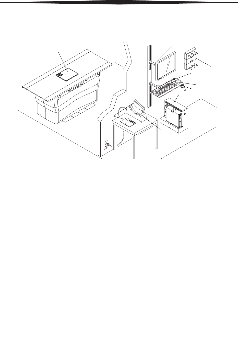
CARESTREAM DRX-1 System
1. DRX-1 System Detector—Captures radiographic images of human
anatomy for display.
2. Console—Controls and records all responses in the imaging process.
3. Monitor—Lets you view the Image Viewer Screen and DIRECTVIEW
Software.
4. Keyboard—Lets you access the Image Viewer Screen and
DIRECTVIEW Software.
5. Mouse—Lets you access the Image Viewer Screen and DIRECTVIEW
Software.
6. DRX-1 System Battery Charger—Charges 3 DRX-1 batteries at one time.
7. DRX-1 System Battery —Provides power to the detector.
8. Bar-code Scanner—Reads the detector bar-code, enters patient data.
9. DRX-1 System Wireless Access Point—Provides communication for the
Wireless System.
CarestreamCarestream DRX1 System
ቨ
ቢ
ቧ
ባ
ብ
ቦ
ቩ
ቤ
ቪ

Hardware and Operation
7H8166 2-3
Cautions
CAUTION:
For continued safe use of this equipment, follow the
instructions contained in this operating manual.
CAUTION:
Study this manual carefully before using the equipment and
keep it at hand for quick reference.
CAUTION:
The system must be used only by qualified personnel and only
after training in the specific operations. It is the operator’s
responsibility to ensure the patient’s safety while the
equipment operates by visual observation, proper patient
positioning, and use of the protective devices provided.
CAUTION:
The detector is fragile and contains glass. Handle with care!
Dropping or rough handling the detector could result in
damage. If the detector is dropped or handled roughly, or if
there is any indication of reduced image quality, perform a
calibration."
CAUTION:
Do not submerge any components of the CARESTREAM DRX-1
System in liquid.
CAUTION:
Perform periodic maintenance to ensure continued safe use of
the equipment.
CAUTION:
The system must be repaired only by authorized service
personnel.
Installing the Hardware
All equipment installations and adjustments must be performed by personnel
authorized by Carestream Health only.
2-4 7H8166
Hardware and Operation
Attaching Accessories The use of equipment and/or hardware that does not comply with the
equivalent product safety and EMC requirements of this product may lead to a
reduced level of safety and/or EMC performance of the resulting system.
Consideration relating to the choice of accessory equipment used with this
product shall include:
• Use of the accessory in the patient’s vicinity.
• Evidence that the safety certification of the accessory has been
performed in accordance with applicable coordinated harmonized
product safety standards per IEC 60601-1-1.
• Evidence that applicable emission certification of the accessory has been
performed.
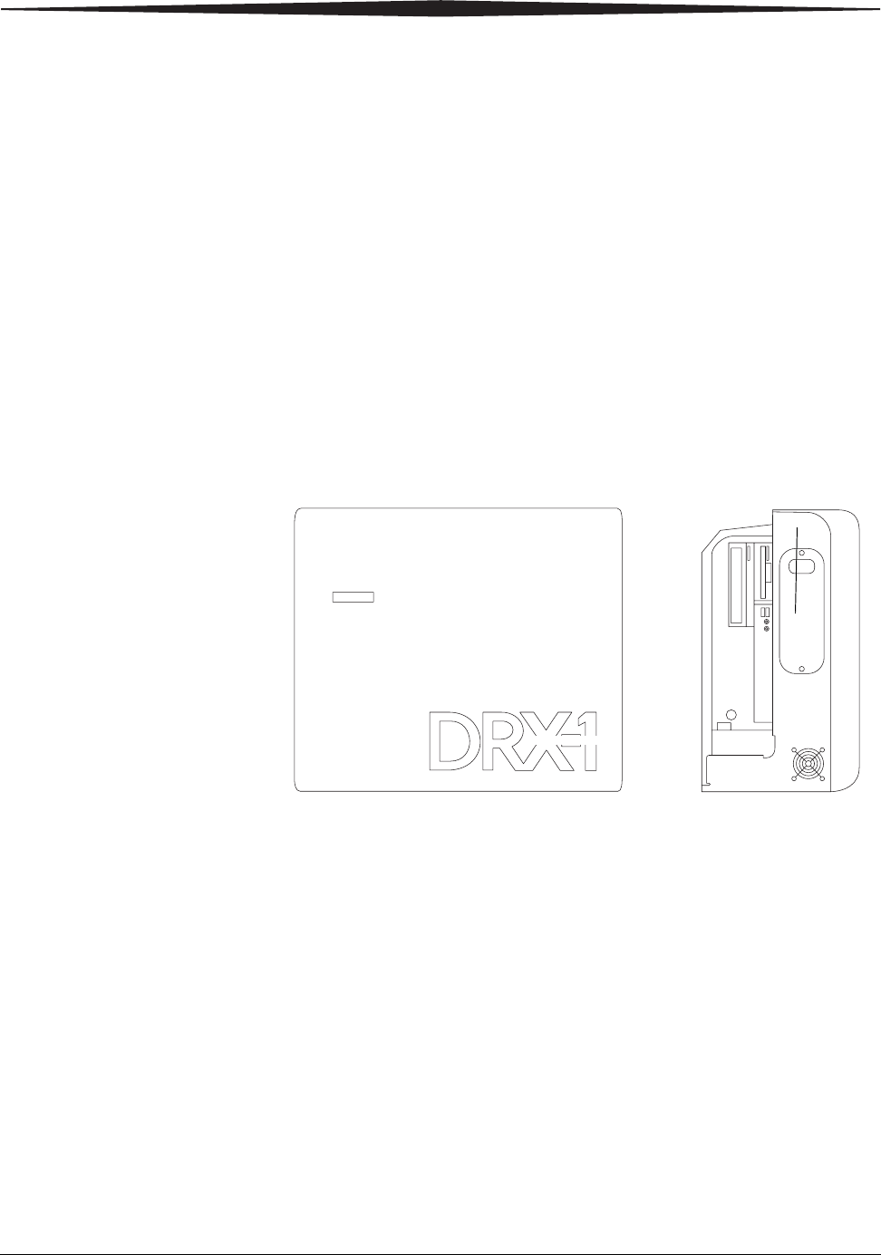
Turning the System
On and Off
To turn the DRX-1 System On:
1. Press the ON switch on the UPS.
2. Press the ON switch on the computer and monitor.
3. When the software initializes, select the DRX-1 icon on the monitor.
To turn the DRX-1 System Off:
1. Select the Quick Menu in the lower left corner of the monitor.
2. Select Shut Down.
3. Turn Off the monitor.
4. Turn Off the UPS.
You can remain in hold-on-prep for up to 15 seconds with the CARESTREAM
DX-1 System Detector and the detector will function properly. In the event of
an aborted exposure, the detector can acquire a subsequent image in four
seconds.
Carestream
Carestream SystemDRX1
UPS

Hardware and Operation
7H8166 2-5
NOTE: In the event of an aborted exposure, the detector acquires the image
and processes it normally. This may result in less than optimal image
quality.
Exposure Time:
The CARESTREAM DRX-1 System Detector can acquire images from exposures
of up to 1 second.
CARESTREAM DRX-1 System Battery
CAUTION:
To assure proper operation, use only the
CARESTREAM DRX-1 System Battery.
The DRX 1 System provides a battery charger with three charging slots for
batteries for the DRX-1 System detector. You can purchase additional batteries
separately. The battery is keyed for proper orientation in the detector.
• A battery is required for wireless or tethered use.
• Minimum battery life 500 charge and discharge cycles where the cell
capacity remains above 80% of initial capacity.
• Expected life 1.5 years, assuming 1 charge per day.
• New battery provides approximately 90 image acquisitions (3.0 hrs heavy
usage).
• A battery charge state is indicated on the Console. The detector
determines if the installed battery is not properly charging, and provides
this battery status to the Console.
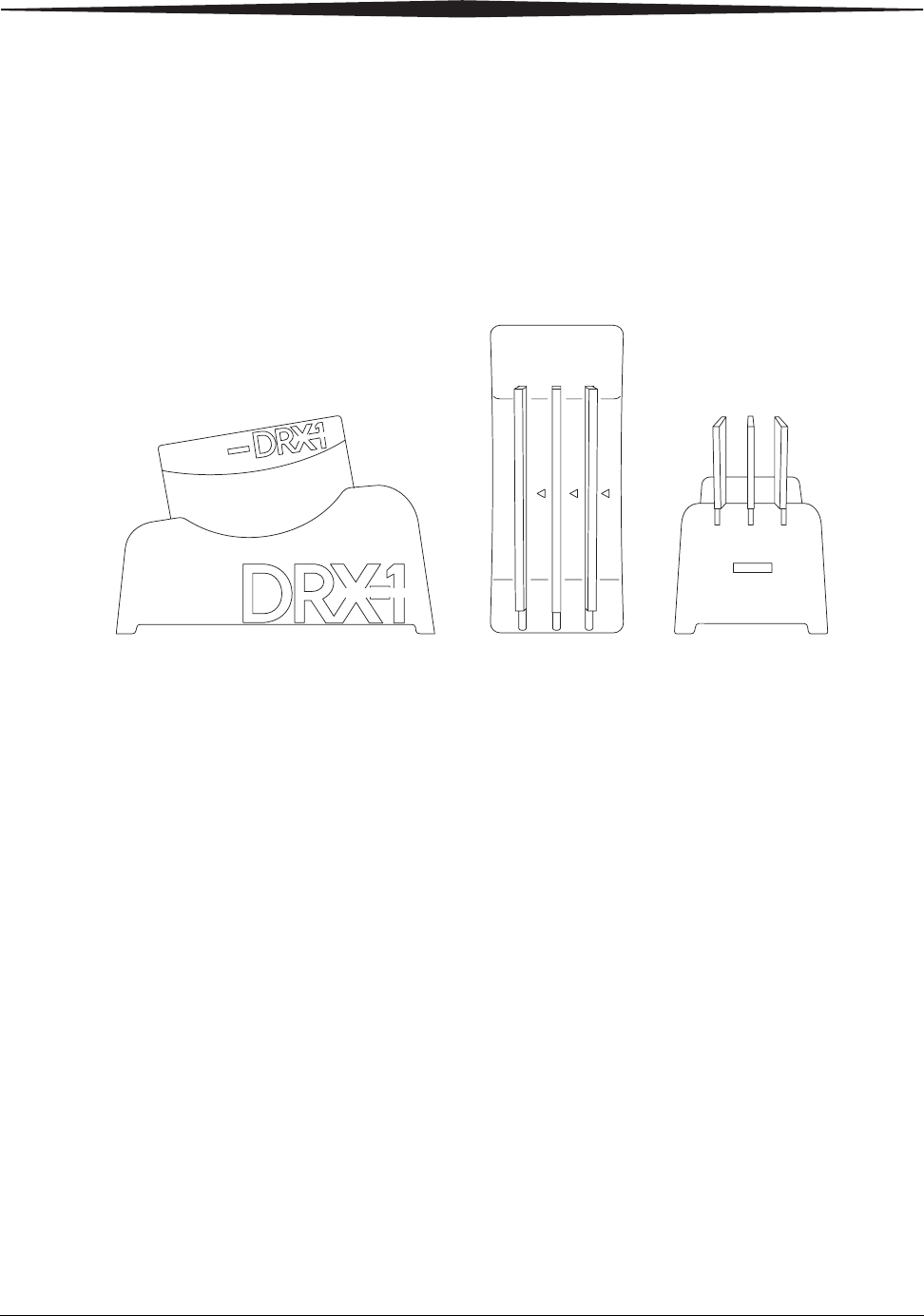
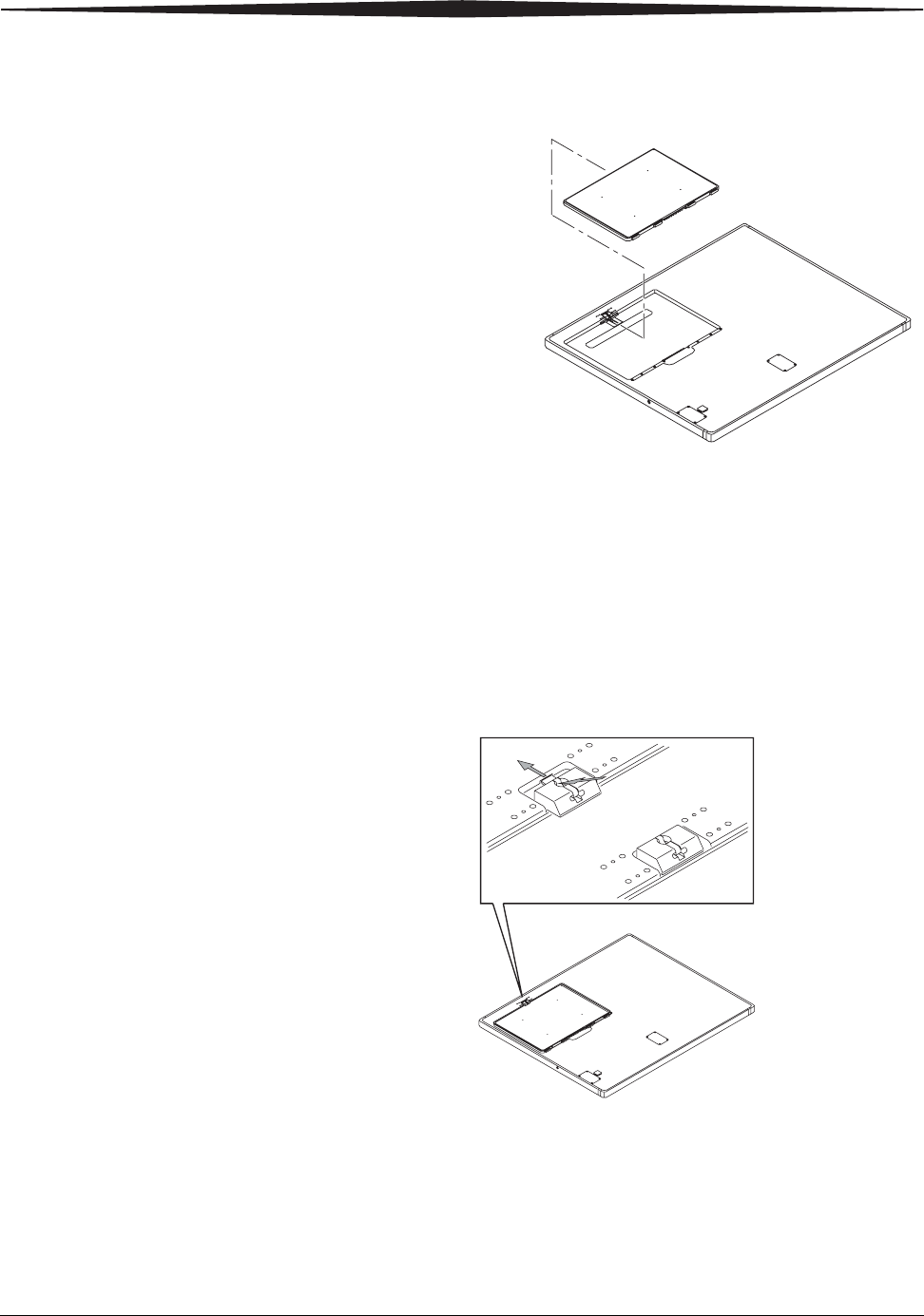
Installing the Battery 1. A fully-charged battery in the DRX-1 System Battery Charger will be
indicated by a green light. The battery fits into the detector only one way.
Place a fully-charged battery in the battery footprint in the DRX-1
detector so that the contacts on the back edge of the battery are inserted
first.
2-6 7H8166
Hardware and Operation
Installing the Battery
2. Push the battery firmly down until the latch catches.
NOTE: See the CARESTREAM DRX-1 System Battery Charger User Guide for
information on the battery and charger use, specifications, and
disposal.
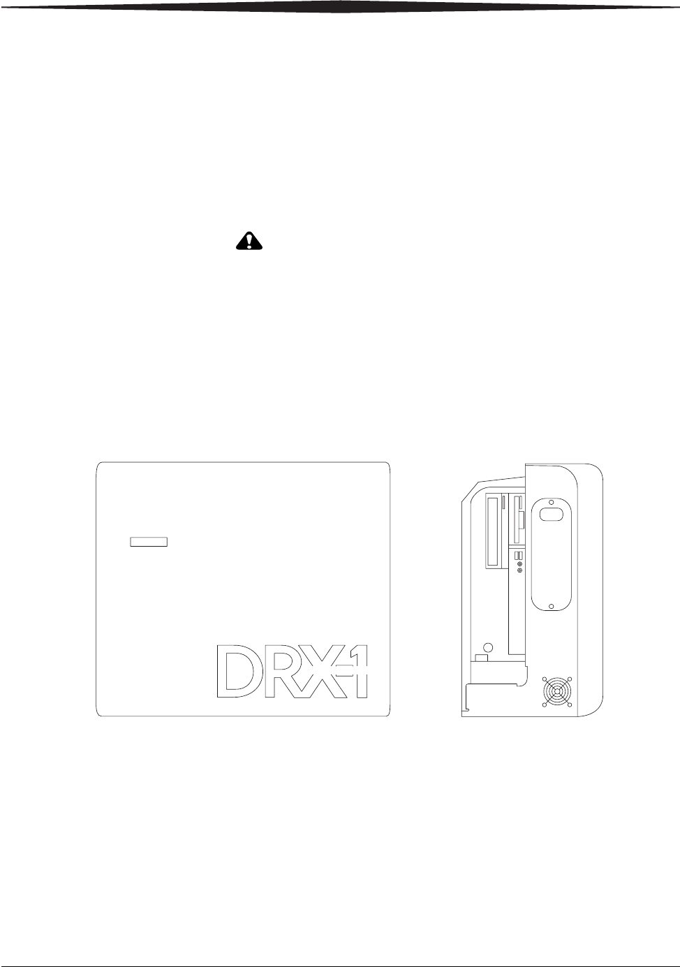
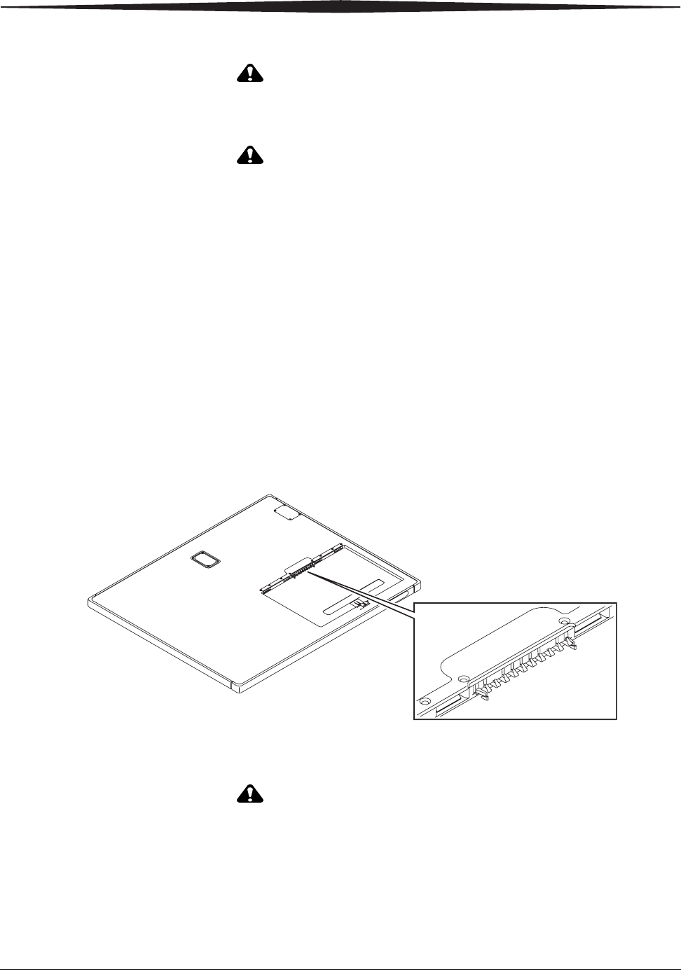
Removing the Battery Place a tool such as a ball-point pen in the release slot and push down on the
latch. The battery releases and pops up for easy removal.
Battery Compartment Latch
Labeling the Detector
The labels that come with the detector help you:
1. Uniquely identify the detector.
H224_0016AC
H224_0017GC
Hardware and Operation
7H8166 2-7
2. Orient the detector correctly in use.
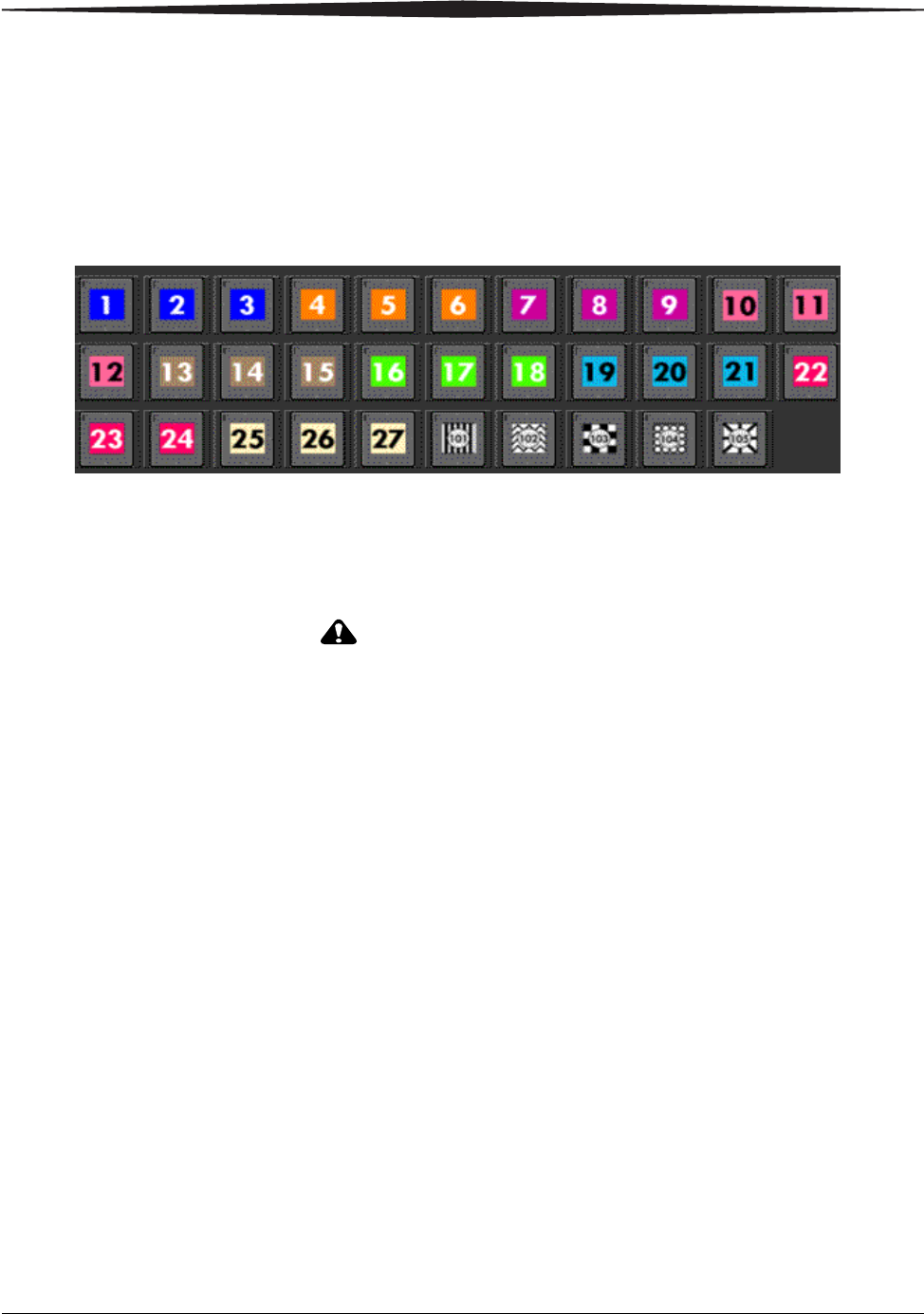
Go to Key Operator Functions > Equipment Management to view the
selections of DRX-1 labels to choose from. Labels are grouped by colors and
number series so that you can keep the same scheme in each room. Make
sure the label you choose is not already in the system.
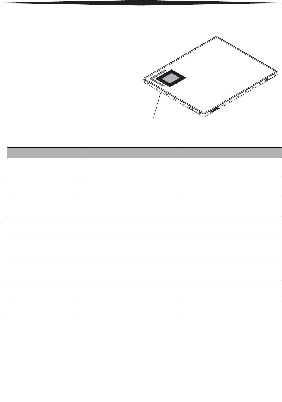
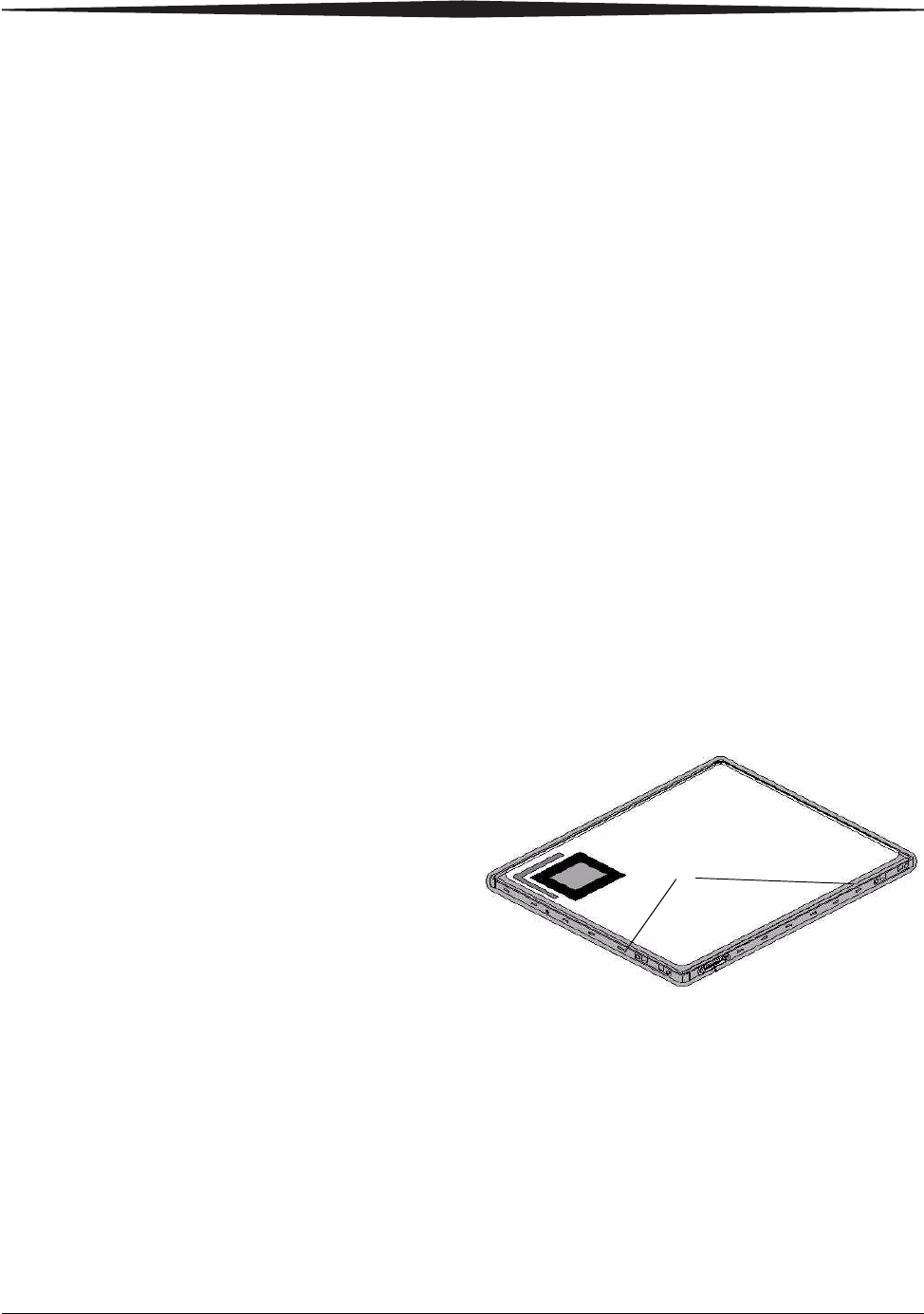
Applying the label:
1. Place the detector on a flat surface with the Tube Side facing you.
2. Place the label inside the Tube Side label as indicated near the tube side
corner label on the detector.
CAUTION:
The detector is fragile and contains glass. Handle with care!
Dropping the detector could result in damage or need for
recalibration.
DRX-1 Detector LED
The detector has one LED that provides a status during operations. The single
LED will alternate with blue and green flashes in various patterns. Green
flashes relate to power. Blue flashes relate to connectivity. No flash pattern is
displayed when the detector is acquiring an image.
2-8 7H8166
Hardware and Operation
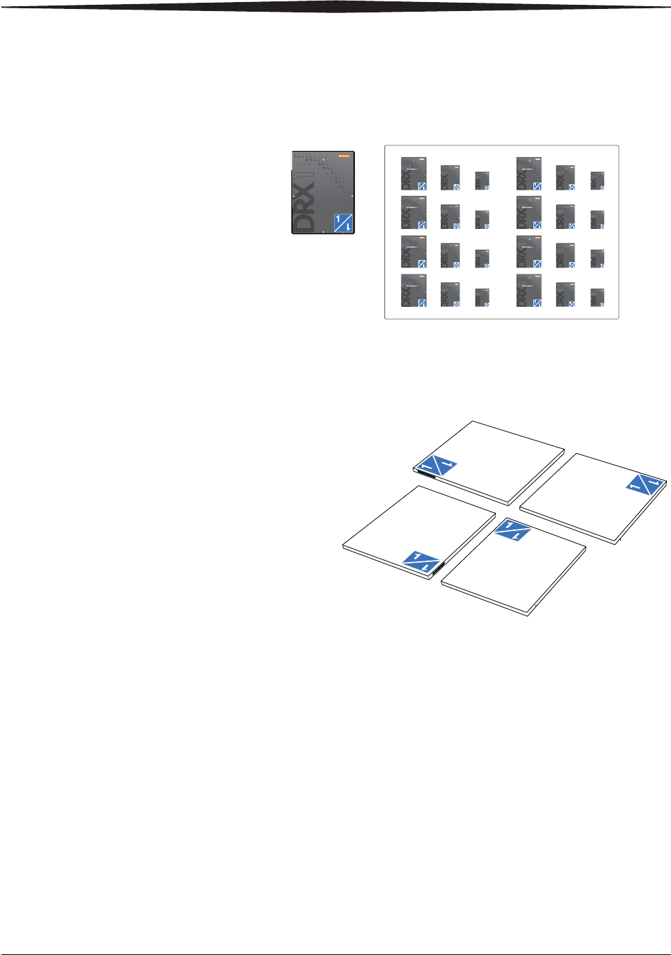
Positioning the Detector in the Bucky
For optimum performance, it is important to position the detector properly in
the Wall Stand Bucky or the Table Bucky when performing an exam. To
provide a visual guide for positioning, Service places a set of two positioning
labels on each Bucky at installation to indicate how to orient the detector for
portrait and landscape exams. To orient the detector properly, hold the
detector so that the position of the ID label on the detector matches the
LED Pattern Meaning Action
1 Green Flash Standby, no study active; Console may
not be connected. Low Power.
No action required. Detector is not being
used.
2 Green Flashes System is on, but not ready. No action required. LED indicates the
detector has been selected.
3 Green Flashes System is on and enabled, but not ready. Should not display in normal operation.
If this pattern is visible, call Service.
4 Green Flashes System is on and enabled, appears while
pressing the prep switch.
Do not report an error if this pattern is
not visible.
5 Green Flashes Power fault has occurred. Detector is
unusable.
Remove and re-insert the battery to clear
the problem. If the problem persists, call
Service.
1 Blue Flash Detector is currently connected to the
System Console.
No action required.
2 Blue Flashes Detector not currently connected. If this pattern occurs while detector is in
use, call Service.
3 Blue Flashes Detector has rebooted and has not yet
connected to System Console.
If pattern occurs when the Detector
should be in use, call Service.
H224_0019AC
LED
Hardware and Operation
7H8166 2-9
position of the orientation label on the portrait or landscape label on the Wall
Stand or Table Bucky.
Positioning Labels
Detector Positioning Labels
DRX1System
CAERSTREAM DRX1System
CAERSTREAM DRX1System
DRX1System
CAERSTREAM DRX1System
DRX1System
CAERSTREAM DRX1System
DRX1System
CAERSTREAM DRX1System
Portrait
Landscape

2-10 7H8166
Hardware and Operation
Example of Labels Applied to Table Bucky
Range of Operation
Using a Single
Detector
A single detector may be placed in a Wall Stand Bucky, in a Table Bucky, on a
table top, in a wheel chair, etc. The detector is registered with the Console for
the room, but it may be registered with other Consoles in other rooms as well.
Name the detector the same name as its icon and add a description to identify
its location. See “Acquiring the Image” on page 3-3 for a description of the
Workflow.
Using Two or More
Detectors
Using two or more detectors in a room makes detector identification even
more important. Make sure that the label on the detector matches the icon on
the Console before exposing the patient. You must use the bar-code scanner
while on the screen to read the bar-code on the detector when moving the
detector to a new room.
IMPORTANT: The system does not automatically select a detector.
Supervise carefully to make sure that the correct detector is
selected.
NOTE: Leave the Wall Stand detector in the Bucky to reduce handling and
assure correct detector selection.
See “Acquiring the Image” on page 3-3 for a description of the Workflow.
Positioning Labels
Hardware and Operation
7H8166 2-11
Using Detectors in
Two or More Rooms
The identification labels make it easy to prevent mixing of detectors from one
room to another. Keep a different color scheme for each room and then
subsequent detectors can be assigned labels within that color.
You can register the same detector on two consoles. For example, you may
use one detector as a “float” detector. The system is designed so that if the
Console cannot communicate with the selected detector, the X-Ray generator
will not fire. The workflow is the same. See the Online Help for information
about workflow.
Wireless Operation
Wireless operation lets you use the detector in an X-ray room without cabling.
Wireless operation produces a direct digital image with the freedom to
position the detector anywhere in the room. Wireless operation is intended
for use in the table Bucky, in the Wall Stand Bucky, on the table top, or in the
auxiliary positions, such as a wheel chair.
NOTE: A charged CARESTREAM DRX-1System Battery must be installed for
wireless use. See “Installing the Battery” on page 2-5.
NOTE: The wireless IP address is registered with the system.
To assure good wireless communication, try to avoid obstructing the antennas
on the two edges of the of the detector as shown.
If the wireless connection fails before an image is sent to the console, the
detector can be connected to a tether to retrieve the image.
Antennas

2-12 7H8166
Hardware and Operation
Tether Operation
The primary function of the tether is to provide power and communications
to the detector while it is positioned in a Bucky.
CAUTION:
Do not allow the detector in tether mode to come in direct
contact with a patient.
The DRX-1 System Detector should be connected to the DRS-1 System Tether
Interface when:
• The detector is located outside the patient vicinity.
• The detector is not being used for an exam.
• The detector is located inside a Bucky or other device that prevents
direct patient contact.
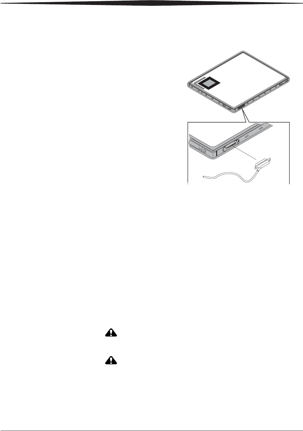
To use the detector in Tether Operation, connect the tether to the detector at
the magnetic connector. If the tether is connected correctly, it will not
interfere with the position of the detector. In addition, the tether:
• Provides power and communications to the detector when connected.
• Protects the detector from damage in handling.
• Eliminates the need to remove the detector to change a battery.
• Improves workflow.
• Does not interfere with grid or ion chamber operation.
To remove the DRX-1 System Detector from the tether and use it wirelessly,
disconnect the tether. Make sure the DRX-1 System Detector comes into
patient contact in wireless mode only.
Hardware and Operation
7H8166 2-13
Tether Connection On Detector
NOTE: The detector will function properly with a non-charged battery
installed when the tether is properly connected and operating. It is
not necessary to remove the battery to recharge it if the battery has
not reached end of life and can be re-charged.
NOTE: With a charged battery in place, image acquisition continues if there
is a loss of tether connection.
NOTE: Additional tethers are available to replace damaged cables.
Tether Interface Box The Tether Interface Box and cables has its own AC Mains power cord and is
located in the X-ray room. The Tether Interface Box is safety certified for
casual patient contact.
Cleaning the Hardware
CAUTION:
Do not operate the equipment when cleaning the equipment.
CAUTION:
Do not spray cleaning solution directly onto the equipment.
moisten a cloth with a 70% Isopropyl alcohol solution and
apply to patient contact areas after each contact.
2-14 7H8166
Hardware and Operation
CAUTION:
Isopropyl alcohol is a flammable solvent. Read and follow
instructions in the Material Safety Data Sheet (MSDS).
CAUTION:
Do not immerse the equipment in liquid.
To clean the detector:
1. Disconnect the detector from its power source.
a. Remove the tether.
b. Remove the battery.
2. Moisten a cloth with a 70% Isopropyl alcohol solution.
3. Apply the moistened cloth to the equipment.
To clean the battery footprint:
1. Wipe the well clean of dust or debris with a soft cloth.
2. Use a brush or vacuum to clean out the prongs in the battery
compartment well, or contact Service for assistance.
With Each Occurrence of Patient Contact
CAUTION:
Do not spray cleaning solution directly onto the equipment.
moisten a cloth with a 70% Isopropyl alcohol solution and
apply to patient contact areas after each contact.
For each occurrence of patient contact:
• Moisten a cloth with the solution.
H224_0045BC

Hardware and Operation
7H8166 2-15
• Apply to the patient contact areas.
CAUTION:
Isopropyl alcohol is a flammable solvent. Read and follow
instructions in the Material Safety Data Sheet (MSDS).
System Maintenance
CAUTION:
Do not attempt mechanical or electrical repair of the
CARESTREAM DRX-1 System. Contact your Service
representative if any unit does not perform to your satisfaction.
The CARESTREAM DRX-1 System must be maintained in good operating order
at all times to provide safe conditions for operating personnel and patients.
The DRX-1 System must also be maintained to prevent possible loss of patient
or image data.

With each occurrence of patient contact:
• See “With Each Occurrence of Patient Contact” on page 2-14.
Daily:
• Clean the equipment.
• Check the integrity of the equipment.
• Daily Refresh Calibration. See Running Detector Calibrations in the
CARESTREAM DRX-1 System Online Help.
Monthly:
• X-ray Calibration. See Running Detector Calibrations in the
CARESTREAM DRX-1 System Online Help.
CAUTION:
The system must be repaired only by authorized service
personnel.
Periodically or as needed:
• Recalibrate the touch-screen on the Console as needed. Recalibration
instructions are included in the CARESTREAM DRX-1 System Online
Help.
• Report any unusual conditions to your authorized service representative.
Checking the
Equipment Integrity
To make sure that the equipment is functioning and operating safely, check
that:
• Fastening hardware connects tightly.
• All name plates, legal labels, and warning labels are legible and secure.
• No cables have abrasions or damage, particularly in locations where
cables are draped and subject to stress.
Grid Recommendation Artifacts are not visible when the following grids are used.
• 103 line pair/inch low frequency stationary grid
Protective Enclosures When there is a risk of fluids contacting the detector, place the detector in a
protective bag. If you are using a protective enclosure around the detector,
remove the enclosure immediately after use to prevent the detector from
overheating.

7H8166 I-1
Index
Numerics
1 blue flash, 2-8
1 green flash, 2-8
2 blue flashes, 2-8
2 green flashes, 2-8
3 blue flashes, 2-8
3 green flashes, 2-8
4 green flashes, 2-8
5 green flashes, 2-8
A
accessories, attaching, 2-3
analog system, 2-1
authorized service personnel, 2-3
B
bar-code scanner, 2-2
Battery, 2-2, 2-5, 2-6, 2-11
battery, 2-1, 2-2, 2-5, 2-12, 2-13
illustration, 2-2
installing
removing
expected life, 2-5
minimum life, 2-5
requirement, 2-5
sleep mode, 2-5
battery charger, 2-2
battery required, 2-5
battery status on console, 2-5
C
cleaning solution, 2-13
cleaning the detector, 2-14
cleaning the equipment, 2-13
CR System, 2-1
D
detector, 2-2
orienting, 2-8
using a single, 2-10
using two or more, 2-10
using two or more rooms, 2-11
weight limit, 1-18
wireless operation, 2-11
detector calibrations, 2-16
detector LED, 2-7
disposal information, 1-23
do not submerge components, 2-3
download from the RIS, 2-1
E
equipment integrity, 2-16
exposure data, 2-1
F
fragile, handle with care, 2-3
G
grid recommendation, 2-16
I
immersing the equipment, 2-14
isopropyl alcohol, using, 2-14
K
keyboard, 2-2
L
label
identifying, 2-7
M
minimum battery life, 2-5
monitor, 2-2
mouse, 2-2
N
new battery life expectation, 2-5

I-2 7H8166
Index
P
patient contact, 2-14
perform periodic maintenance, 2-3
protective enclosures, 2-16
R
radiographer, 2-1
repairing the detector, 2-15
S
spraying cleaning solution, 2-13
System, 2-2
system console label, 1-20
system interface box label, 1-22
system overview, 2-1
T
tether, 2-1
removed during the exam, 2-13
removing, 2-12
replacement, 2-13
tether interface label, 1-21
traditional film, 2-1
turning the system off, 2-4
turning the system on, 2-4
U
using film or CR system, 2-1
W
weight label, 1-18
weight limit, detector, 1-18
wireless operation, 2-11

150 Verona St.
Rochester, NY 14608
CARESTREAM is a trademark of Carestream Health, Inc.
© Carestream Health, Inc. 2008.
7H8166
Carestream Health, Inc.