Carewell Electric Technology AC83T REMOTE CONTROL User Manual EN52r 35T 3F7
Carewell Electric Technology (Zhongshan) Co., Ltd. REMOTE CONTROL EN52r 35T 3F7
UserManual.wiki
>
Carewell Electric Technology
>
AC83T User Manual
>
User manual
Contents
1.
User manual
2.
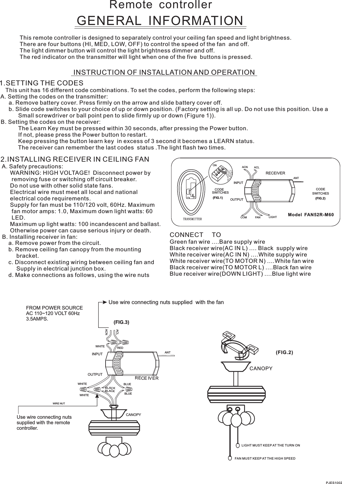
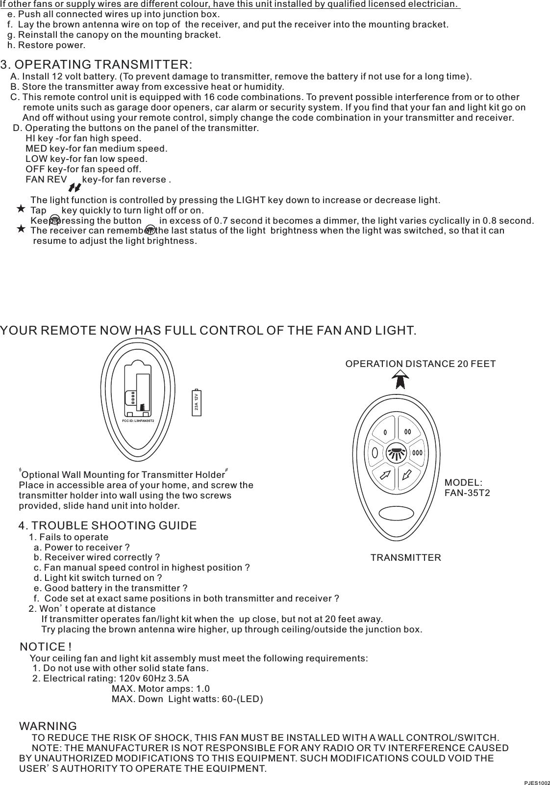
User Manual
User manual
Navigation menu
Upload a User Manual
Namespaces
Wiki Guide
HTML
PDF
Info
Views
User Manual
Discussion / Help
Navigation