Carl Zeiss Surgical 304970-9200 Wireless Footswitch User Manual G 30 1707 bk
Carl Zeiss Surgical GmbH Wireless Footswitch G 30 1707 bk
User Manual
Carl Zeiss
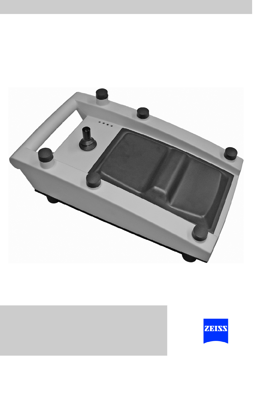
cççí=`çåíêçä=m~åÉä
c`m=fåíÉêÑ~ÅÉ=C=c`m=ti=fåíÉêÑ~ÅÉ
User Manual
G-30-1707-en
Version 1.0
11.07.2008

Foot Control Panel FCP Interface & FCP WL Interface
Version 1.0
Page 2 G-30-1707-en
About this manual The user manual is part of the scope of delivery.
• Carefully read it before using the device.
• Keep it at the site of use of the foot control panel.
• Store it for the entire service life of the foot control panel.
• Pass it on to every subsequent owner or user of the foot control panel.
Orientation aids – The chapter overview at the beginning of the user manual provides a sum-
mary of all subjects.
– The contents of each chapter are specified in detail at the beginning of
each chapter.
– A keyword index at the end of the manual facilitates the search for specific
terms.
Applicable area This user manual applies to the foot control panel with the following identifi-
cation:
– Rating label numbers:
304970-9100-000 / 304970-9300-000
304970-9200-000 / 304970-9400-000
Information on the manufacturer:
Subject to change in design and scope of delivery and as a result of ongoing
technical development. Printed in Germany.
© Carl Zeiss Surgical GmbH 2008
Carl Zeiss Surgical GmbH
A Carl Zeiss Meditec Company
73446 Oberkochen
Germany
Fax: + 49 (0) 7364 - 20 4823
Email: surgical@meditec.zeiss.com
Internet: www.meditec.zeiss.com
Foot Control PanelFCP Interface & FCP WL Interface
Version 1.0
G-30-1707-en Page 3
Chapter overview
Chapter: Safety measures 5
Chapter: Design and function 19
Chapter: Preparations for use 33
Chapter: Operation 43
Chapter: What to do in the event of malfunctions 45
Chapter: Care and maintenance 51
Chapter: System data 55
Chapter: Index 61

Foot Control Panel FCP Interface & FCP WL Interface
Version 1.0
Page 4 G-30-1707-en
Version 1.0
G-30-1707-en Page 5
Foot Control PanelFCP Interface & FCP WL Interface
Safety measures
We would like to provide you with information about safety aspects which
must be observed when handling this foot control panel. This chapter con-
tains a summary of the most important information concerning matters rele-
vant to instrument safety.
Key to the symbols in this user manual .............................................6
Hazard symbols ...........................................................................................6
Information symbols....................................................................................7
Directives and standards ...................................................................7
Target group .....................................................................................8
Field of application ............................................................................8
Intended use ...............................................................................................8
Typical misuse .............................................................................................8
Notes for the operator.......................................................................9
Duties of the operator .................................................................................9
Requirements to be met by the user ..........................................................12
Warranty and liability.................................................................................13
Requirements for operation.............................................................14
Before every use........................................................................................14
During use.................................................................................................14
After every use ..........................................................................................15
Warning labels and notes ................................................................16
Safety measures Foot Control Panel FCP Interface & FCP WL Interface
Version 1.0
Page 6 G-30-1707-en
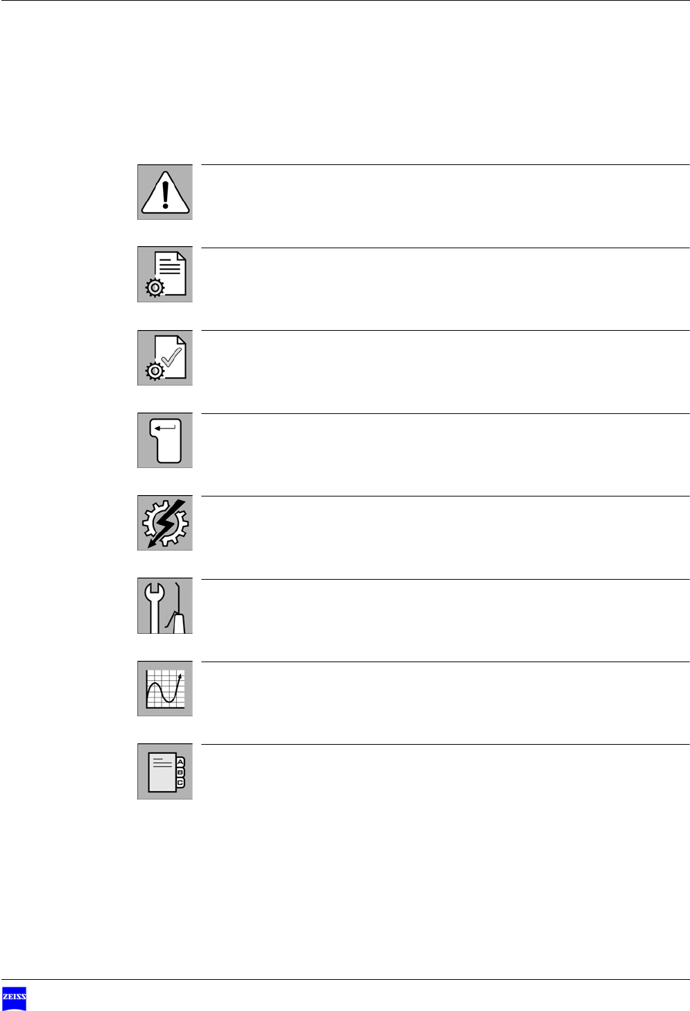
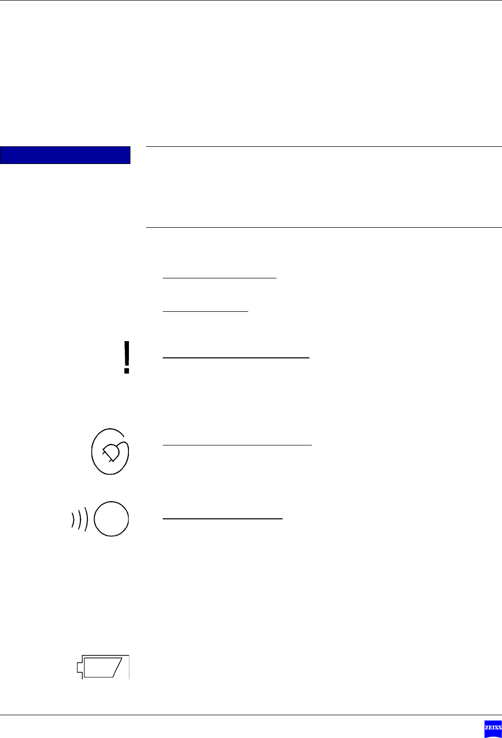
Key to the symbols in this user manual
Hazard symbols
The following safety information has been incorporated in the user manual.
Please note this information and be particularly careful in these cases.
The following symbols indicate special hazards to persons, property or the en-
vironment.
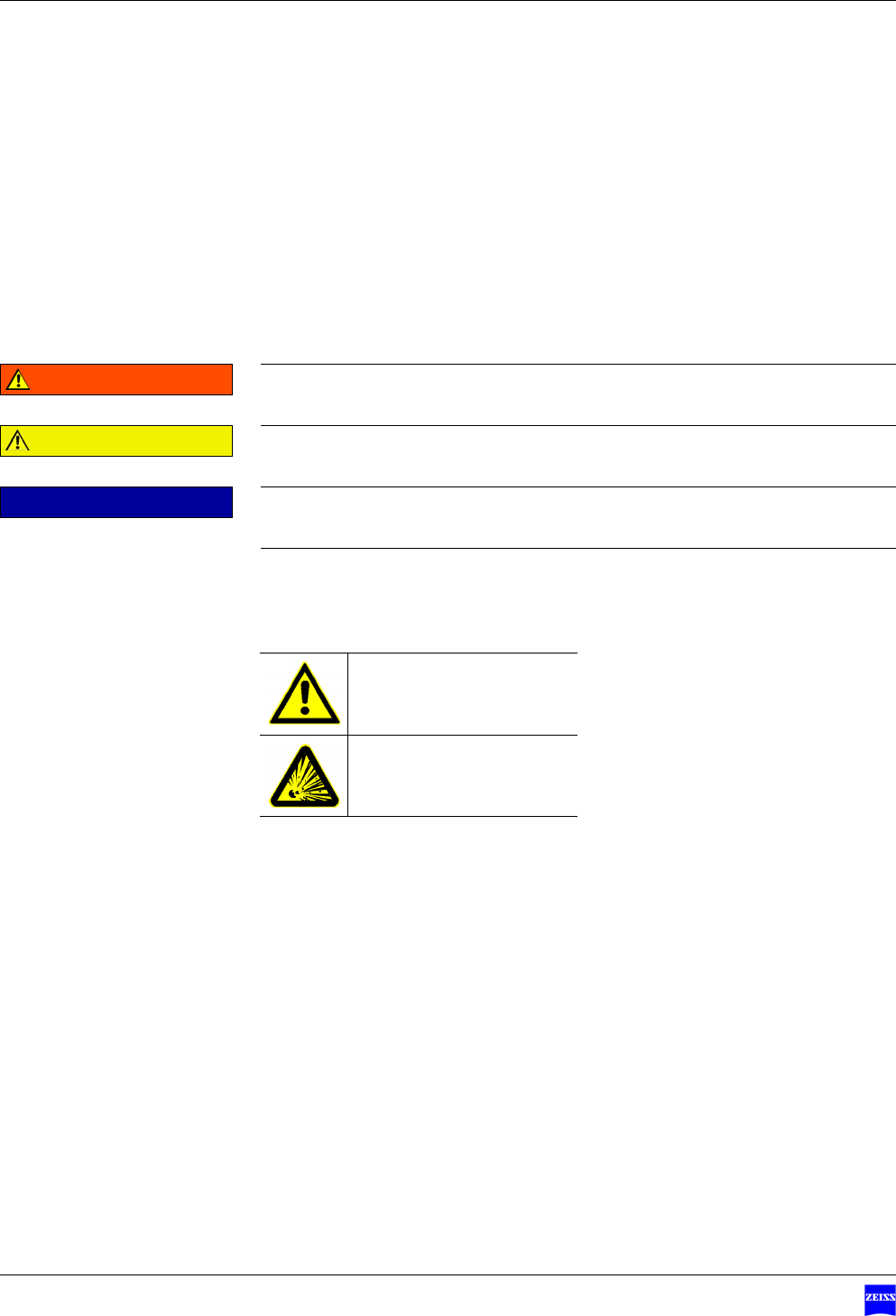
WARNING Indicates a hazard which can lead to death or severe injury if it is not pre-
vented.
CAUTION Indicates a hazard which can cause slight and medium injury if it is not pre-
vented.
NOTE Indicates a hazard which can cause damage to material if it is not pre-
vented.
Warning of a general
hazard
Warning of explosion risk
Version 1.0
G-30-1707-en Page 7
Foot Control PanelFCP Interface & FCP WL Interface Key to the symbols in this user manual
Information symbols
The following information symbols are used in this user manual:
–Listing
9Prerequisite for an action
• Prompt for action
ÆResult of an action
Additional information and tips.
No warnings of hazards are provided.
Directives and standards
The foot control panel described in this manual has been designed and tested
in accordance with Carl Zeiss safety standards as well as German and interna-
tional standards. This guarantees a high degree of safety.
The foot control panel has been designed in compliance with the require-
ments of:
–EN (European standard)
– IEC (International Electrotechnical Commission)
– UL (Underwriters Laboratories)
In accordance with Directive 93/42/EEC for medical devices, the complete
quality management system of the company Carl Zeiss Surgical GmbH, 73446
Oberkochen, Germany, has been certified by DQS Deutsche Gesellschaft zur
Zertifizierung von Managementsystemen GmbH, a notified body, under reg-
istration number 250758 MP23.

Safety measures Foot Control Panel FCP Interface & FCP WL Interface
Version 1.0
Page 8 G-30-1707-en
Target group
This user manual is intended for physicians, nurses and other medical staff
who prepare, operate or maintain the foot control panel after appropriate
training and in accordance with the instructions given in this manual. Installa-
tion and service work not described in this manual must only be performed by
specialists from Carl Zeiss.
Field of application
Intended use
This foot control panel permits either cordless or corded operation of up to
14 different functions of a surgical microscope, including its options, by foot
control.
Typical misuse
The foot control panel must only be operated in combination with devices
from Carl Zeiss.

Version 1.0
G-30-1707-en Page 9
Foot Control PanelFCP Interface & FCP WL Interface Notes for the operator
Notes for the operator
The correct use of the foot control panel is absolutely vital for safe operation.
Therefore, please thoroughly familiarize yourself with the content of this user
manual before starting up the foot control panel. Please also observe the user
manuals of the other devices used. Further information is available from our
service department or from authorized representatives.
Duties of the operator
Notes on the
foot control panel
• Make sure that the installation conditions and the use of the foot control
panel meet microsurgical requirements:
–low vibration
– clean environment
– avoidance of extreme mechanical stress.
• Observe the legal regulations for accident prevention and occupational
health and safety applicable in the country concerned.
• Do not operate the components contained in the delivery package
– in explosion-risk areas,
– if inflammable anesthetics or volatile solvents such as alcohol, benzine
or similar chemicals are present at a distance of less than 25 cm.
• Switch off the connected foot control panel and remove the batteries if
you notice any smoke, sparks or unusual noise. Do not use the foot con-
trol panel until it has been repaired by our service team.
• Do not force cable connections. If the male and female parts do not read-
ily connect, make sure that they are appropriate for one another. If any of
the connectors are damaged, have our service representative repair them.
• Over long distances (e.g. removal, return for repair, etc), the foot control
panel must always be transported in the original packaging or in special
return packaging. For details, please contact your dealer or the Carl Zeiss
service team.
• Use the foot control panel only for the application described.

Safety measures Foot Control Panel FCP Interface & FCP WL Interface
Version 1.0
Page 10 G-30-1707-en
• Operate the foot control panel only with the components included in the
delivery package. If you wish to use other components, make sure that
Carl Zeiss or the manufacturer of the components has verified and con-
firmed that these components meet the respective safety standards and
can be used without risk.
• If a failure occurs which you cannot correct with the aid of the chapter
"What to do in the event of malfunctions“, attach a sign to the foot con-
trol panel stating it is out of order and contact our service representative.
The foot control panel is a high-grade technological product. To ensure op-
timum performance and safe working order, we recommend having it
checked by our service representative as part of regular scheduled mainte-
nance.
Notes on EMC (Electro-
magnetic Compatibility)
The foot control panel complies with the EMC requirements of
IEC 60601-1-2. For operating the foot control panel, observe the EMC precau-
tions specified below.
• Only use options approved by Carl Zeiss for this foot control panel.
• Do not use any portable or mobile HF communication equipment in the
vicinity of the foot control panel as this may lead to an impairment of the
foot control panel's function.
• The foot control panel meets the RFI requirements of Class B. It cannot be
ruled out, however, that interferences may occur in HF receivers (e.g. TV
or radio sets) in the vicinity. If such interferences are noticed, please in-
form the Carl Zeiss Service Dept.
Information on exposure to radio frequency radiation in accordance
with FCC
The emitted output power of the component is far below the FCC limit values
for radio frequency exposure. Nevertheless, the component should be used in
such a way that potential contact with persons during normal operation is
kept to a minimum.
NOTE Class
This Class B digital component complies with Canadian standard ICES-003.

Version 1.0
G-30-1707-en Page 11
Foot Control PanelFCP Interface & FCP WL Interface Notes for the operator
NOTE Limit values for digital devices
This component has been tested and found to comply with the limits for a
Class B digital device in accordance with Part 15 of FCC regulations. These
limits have been stipulated to provide adequate protection against harmful
exposure when the component is operated in residential areas. This compo-
nent generates and uses radio frequency energy and may emit such energy.
If not installed and used in accordance with the relevant instructions, it may
cause interference to radio communication. However, there is no guarantee
that interference will not occur in a particular installation. If this component
causes interference with radio and TV reception, which can be determined
by turning the component off and on, the user should try to correct the in-
terference by one or several of the following measures:
– Relocate or reorient the receiving antenna.
– Move the component further away from the receiver.
– Plug the component into a different outlet so that it is not on the same
circuit as the receiver.
– Consult an experienced radio/TV technician.
NOTE Part 15 of FCC regulations
This component complies with Part 15 of FCC regulations [and with the In-
dustry Canada RSS-210 standard].
Operation of the component is subject to the following two conditions:
– the component must not cause any harmful interference and
– the component must accept any interference received, including interfer-
ence that may cause undesired operation
NOTE Modification or conversion
Any modification or conversion not explicitly approved by Carl Zeiss will in-
validate the FCC license for the operation of this component.

Safety measures Foot Control Panel FCP Interface & FCP WL Interface
Version 1.0
Page 12 G-30-1707-en
Requirements to be met by the user
• The foot control panel must only be used by staff who have undergone
appropriate training and instruction. It is the duty of the customer or insti-
tution operating the component to provide training and instruction for the
relevant staff.
• Please keep the user manual where it is easily accessible at all times for the
persons operating the system.
• Modifications and repairs of the foot control panel or any components op-
erated together with the foot control panel may only be performed by our
service representative or by other authorized persons.

Version 1.0
G-30-1707-en Page 13
Foot Control PanelFCP Interface & FCP WL Interface Notes for the operator
Warranty and liability
Warranty and liability depend on the applicable contractual stipulations.
NOTE Loss of warranty
The manufacturer is not liable for any damage caused by unauthorized per-
sons tampering with the foot control panel. Furthermore, this will forfeit any
rights to claim under warranty.

Safety measures Foot Control Panel FCP Interface & FCP WL Interface
Version 1.0
Page 14 G-30-1707-en
Requirements for operation
Our service representative or an expert authorized by us will install the foot
control panel. Please ensure that the following requirements are met for fur-
ther operation:
9The connecting components have been properly connected. The screw
connections have been firmly tightened.
9All cables and plugs are in perfect condition.
Before every use
• Make sure that all ”Requirements for operation” are fulfilled.
• Go through the checklist.
• Reattach any covers or caps that were removed from the foot control pan-
el. Close any existing openings with the corresponding caps.
During use
• Constantly monitor the foot control panel during use.
Version 1.0
G-30-1707-en Page 15
Foot Control PanelFCP Interface & FCP WL Interface Requirements for operation
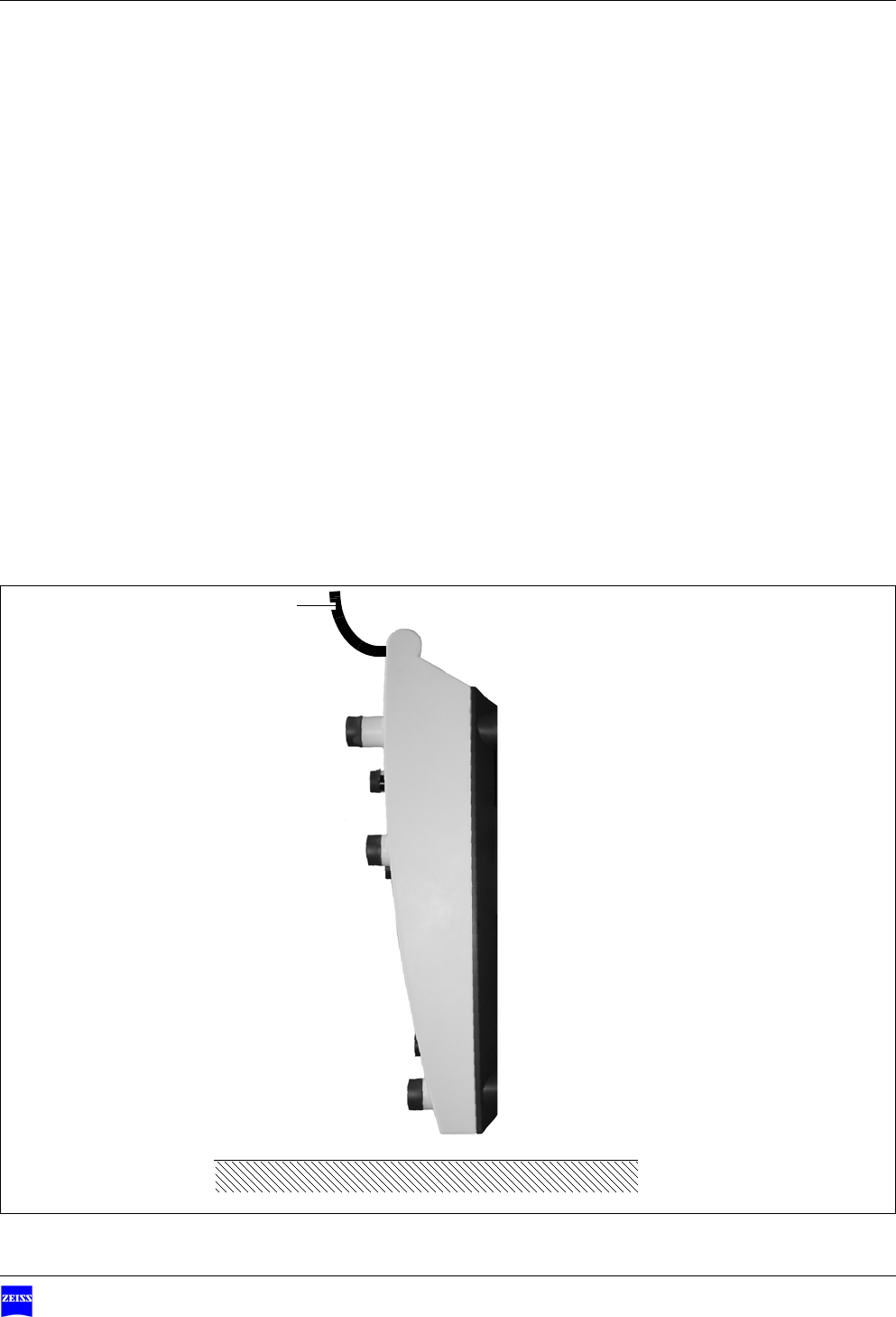
After every use
• Put the foot control panel in its rest position by attaching its bracket e.g.
to the suspension system (1).
ÆThe foot control panel is shut down in the rest position to save energy.
1
Safety measures Foot Control Panel FCP Interface & FCP WL Interface
Version 1.0
Page 16 G-30-1707-en
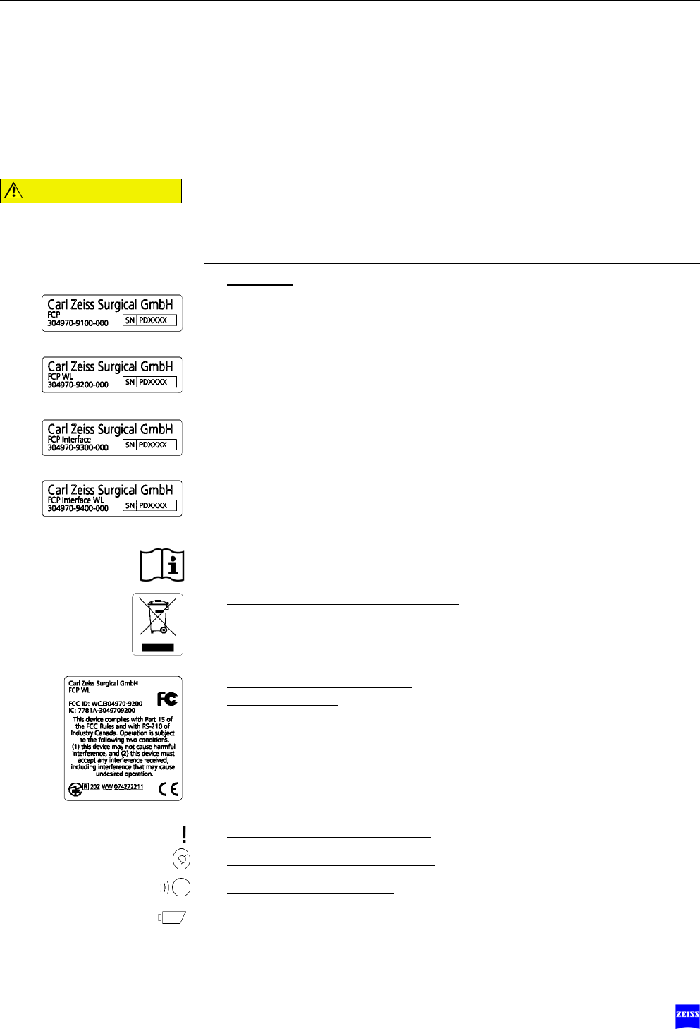
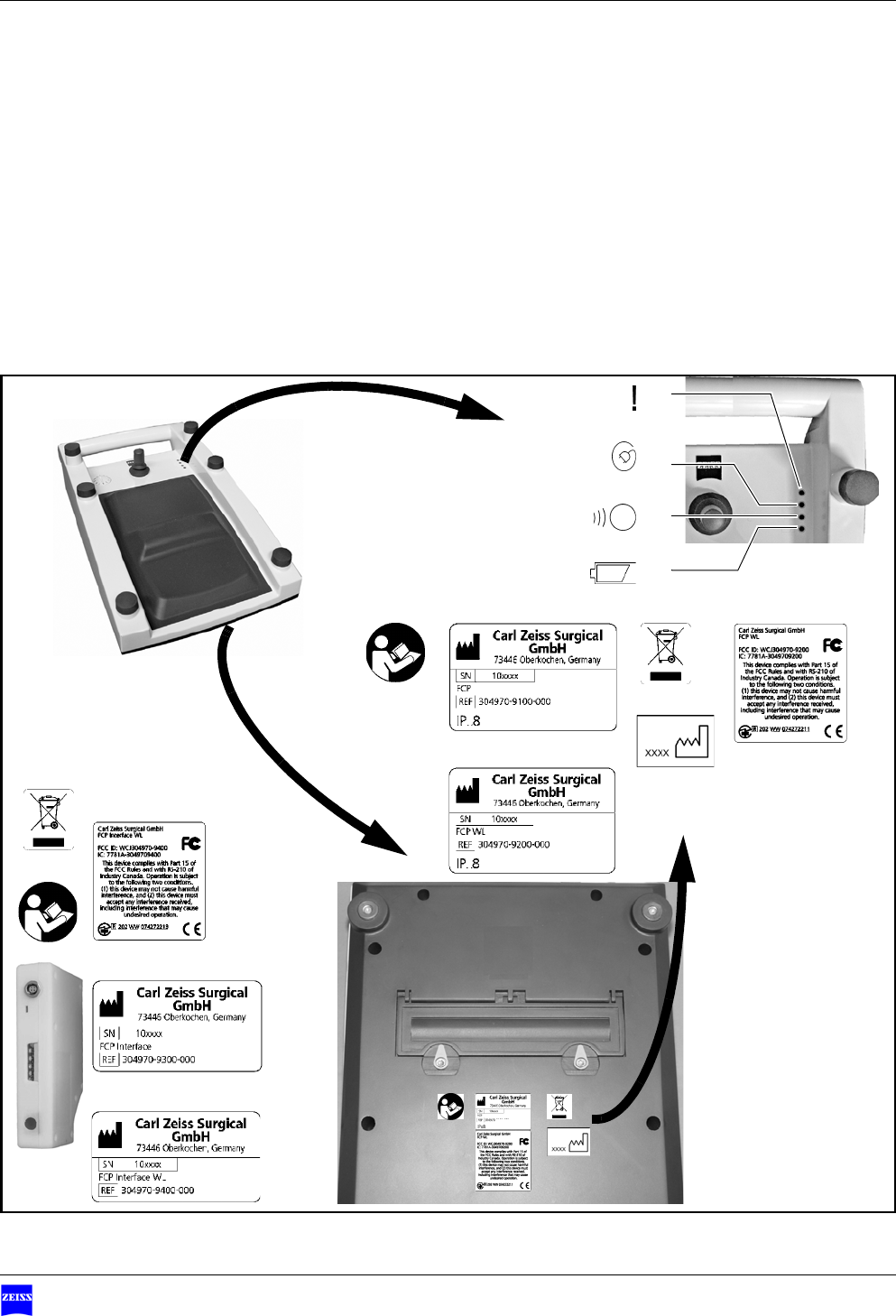
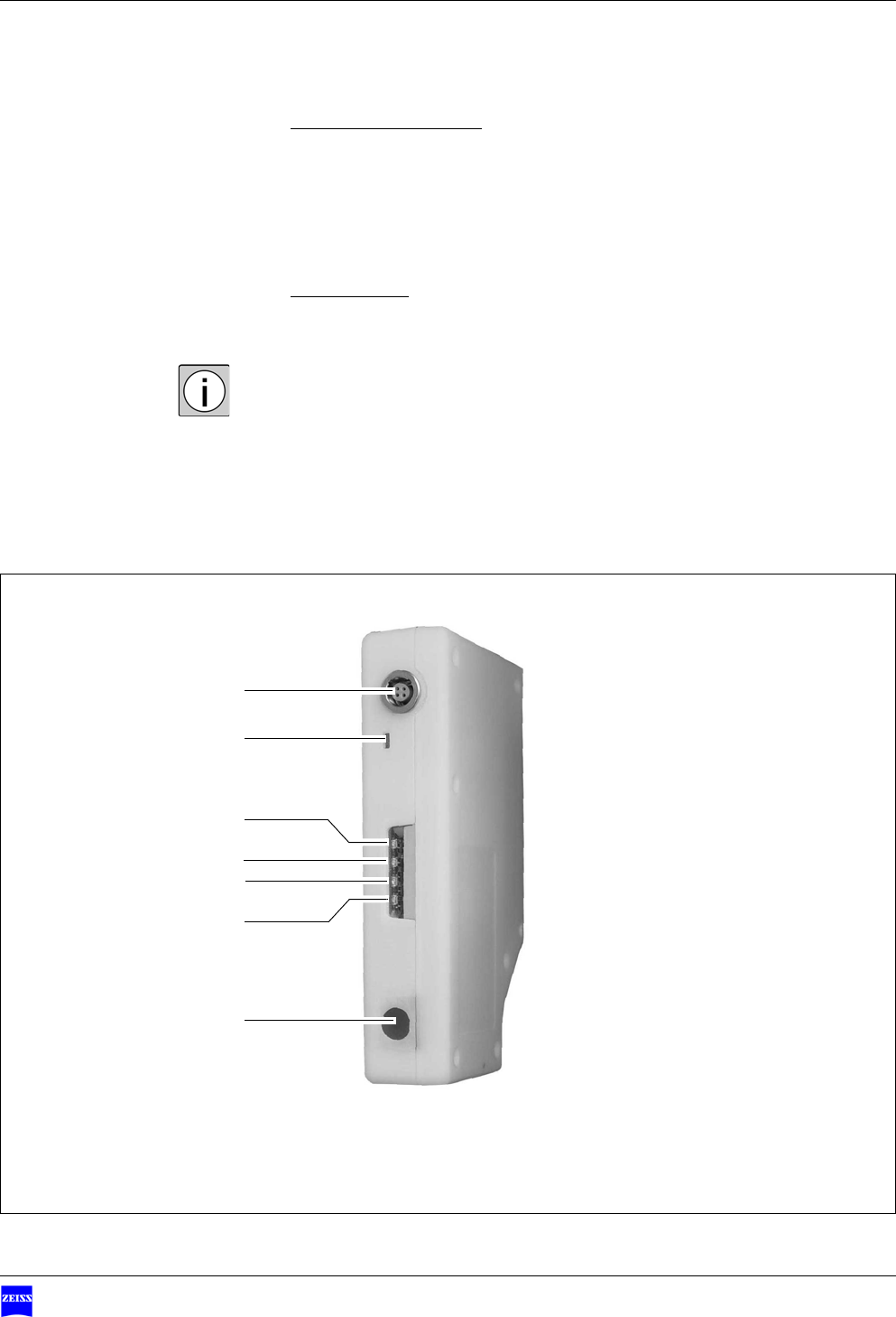
Warning labels and notes
1Type label
A - label for the corded version of the FCP
B - label for the cordless version of the FCP
C - label for the corded version of the FCP interface
D - label for the cordless version of the FCP interface
– Manufacturer (company name)
–Product name
–Catalog number
– Serial number
2Label "Observe the user manual"
Observe the user manual or further applicable documents.
3"Observe disposal regulations" label
Electrical or electronic devices must not be disposed of as normal domestic
waste. For more information on the disposal of electrical and electronic
devices, please see the chapter "Maintenance and care".
4Radio approval identification
(for FCP WL only)
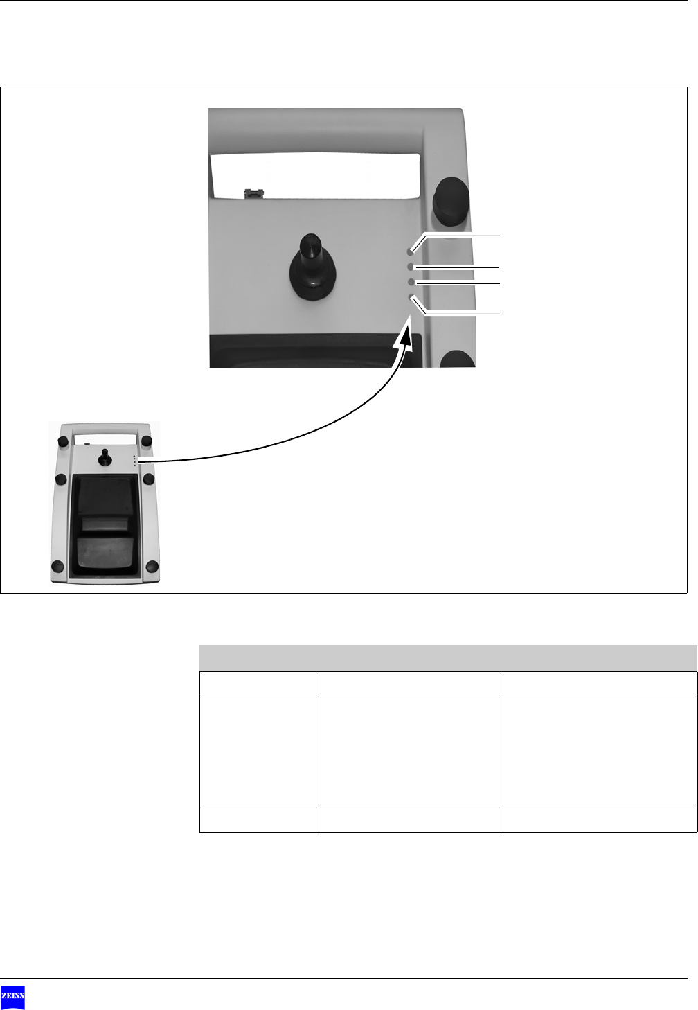
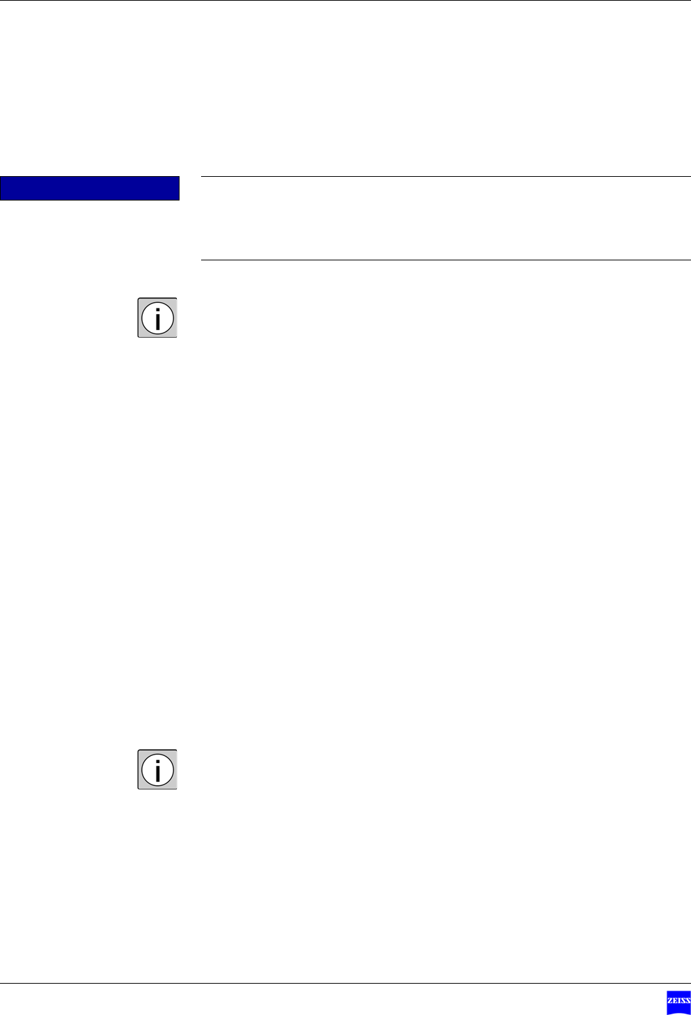
5"Ready for use" status indicator
6Cable connection status indictor
7Radio link status indicator
8Battery status indicator
CAUTION Note the warning labels and notes!
• If you notice that any label on your foot control panel is missing or has
become illegible, please contact us or one of our authorized representa-
tives. We will supply a replacement.
1A
1B
1C
1D
Version 1.0
G-30-1707-en Page 17
Foot Control PanelFCP Interface & FCP WL Interface Warning labels and notes
1 C
1 D
1 A
1 B
23
6
7
9
8
5
4
2
3
5
X
X

Safety measures Foot Control Panel FCP Interface & FCP WL Interface
Version 1.0
Page 18 G-30-1707-en

Version 1.0
G-30-1707-en Page 19
Foot Control PanelFCP Interface & FCP WL Interface
Design and function
Versions of the foot control panel ...................................................21
Components of the foot control panel.............................................22
Standard assignment in the longitudinal configuration ...................26
Standard assignment in the transverse configuration......................28
Upgrade module..............................................................................30

Design and function Foot Control Panel FCP Interface & FCP WL Interface
Version 1.0
Page 20 G-30-1707-en
Version 1.0
G-30-1707-en Page 21
Foot Control PanelFCP Interface & FCP WL Interface Versions of the foot control panel
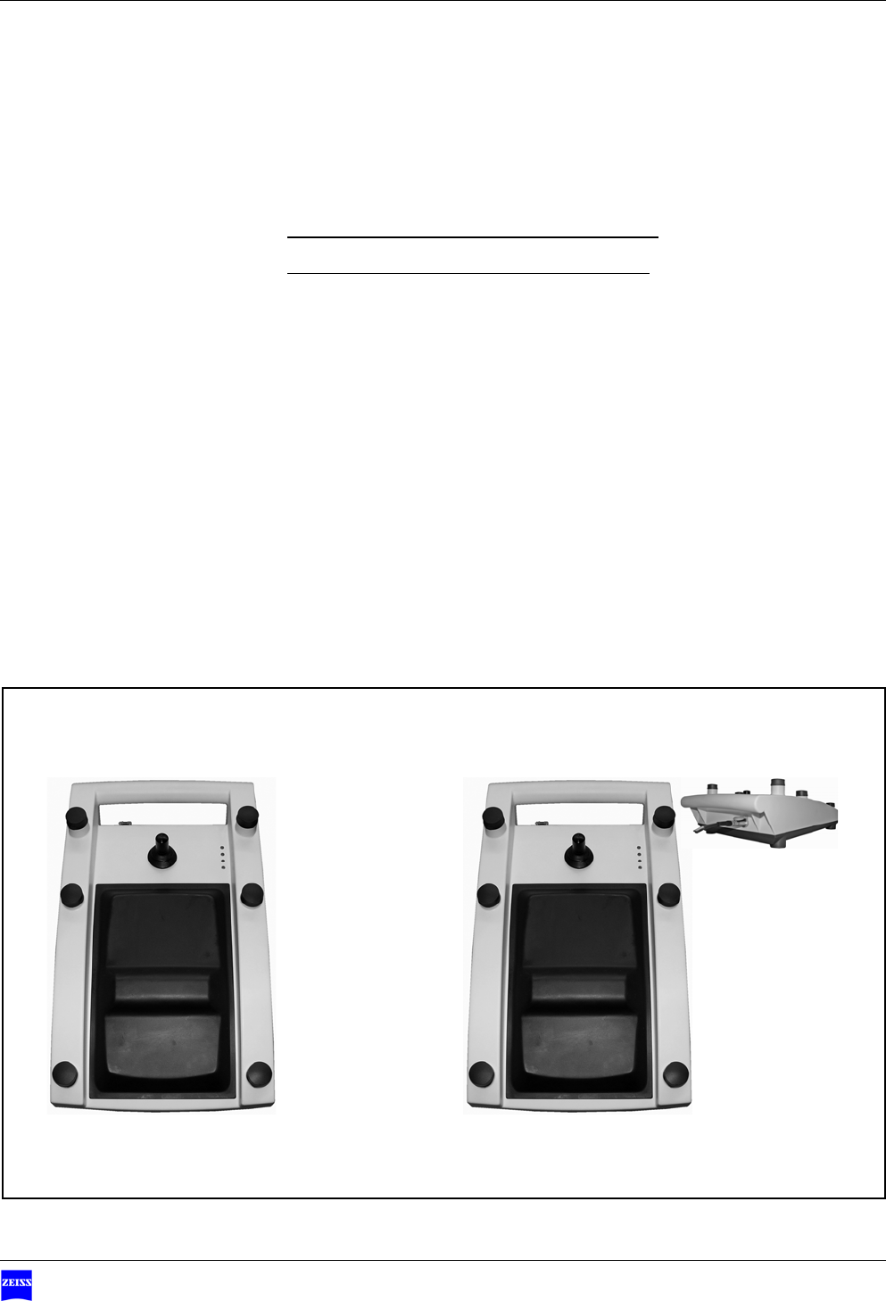
Versions of the foot control panel
1Cordless foot control panel with 14 functions
2Corded foot control panel with 14 functions
12
Design and function Foot Control Panel FCP Interface & FCP WL Interface
Version 1.0
Page 22 G-30-1707-en
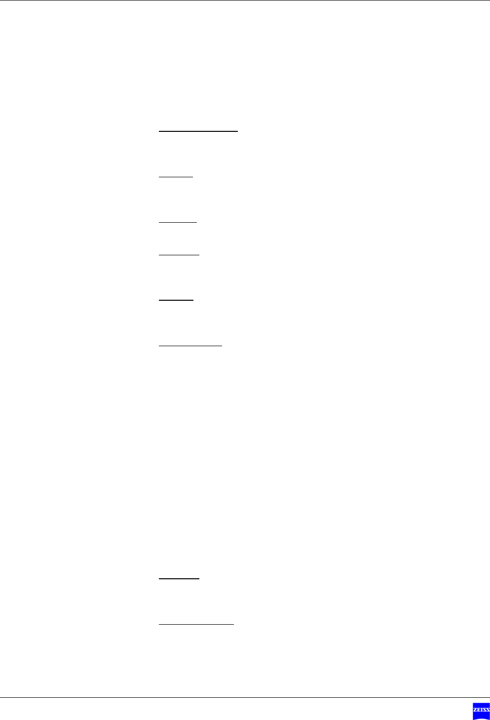
Components of the foot control panel
1Connection cable
Connects the foot control panel to the appropriate connector on a sus-
pension system or wall-mounted control panel.
2Bracket
Allows you to hang up the foot control panel on the floor stand or on the
wall when not in use.
3Controls
Buttons operated with your foot.
4Indicator
The indicator is adjustable. It indicates the assignment to a surgical micro-
scope after pairing.
5Joystick
Permits you to control e.g. an X-Y coupling or the motorized lateral and
front-to-back tilt of the surgical microscope.
6Rocker switch
The two rocker switches are used to operate the ”Zoom” and ”Focus”
functions. For this, each of the rocker switches contains two switching el-
ements, allowing you to control the functions by toe and heel movement
without the need to shift your foot.
You can optionally assign the ”Zoom” and ”Focus” functions to the
switching elements of the rocker switches using the relevant switch of the
upgrade module (see page 30).
ALongitudinal configuration:
The left elements of the rocker switches are used to operate the ”Zoom”
function. The right elements of the rocker switches are used to operate
the ”Focus” function. For more information, please see page 26.
BTransverse configuration:
The elements of the front rocker switch are used to operate the ”Focus”
function. The switching elements of the back rocker switch are used to
operate the ”Zoom” function. For more information, please see page 28.
7Foot rest
The bridge between the two rocker switches (6) serves as a support to
rest your foot on.
8Status indicators
Indicate different statuses by shining/not shining.
Version 1.0
G-30-1707-en Page 23
Foot Control PanelFCP Interface & FCP WL Interface Components of the foot control panel
5
AB
Zoom Focus
Focus
Zoom
1
2
6
7
6
3
3
3
3
33
4
33
3 3
8
Design and function Foot Control Panel FCP Interface & FCP WL Interface
Version 1.0
Page 24 G-30-1707-en
Functions of the status indicators
– During cordless operation, the "ready for use", "radio link" and "battery"
status indicators are only lit if two buttons are simultaneously pressed, one
on the left and one on the right side of the foot control panel.
– During corded operation via the connection cable, the "ready for use" and
"cable connection" status indicators are permanently lit.
1"Ready for use" status indicator
– Shining green: the foot control panel is ready for use, no error is
present.
– Shining red: the foot control panel is not ready for use, an error is
present.
2Cable connection status indictor
– Shining: the connection cable has been connected, power supply is
present.
– Not shining: the foot control panel operates in the cordless mode.
3Radio link status indicator
– Shining green: very good radio link
– Shining yellow: reduced radio link, e.g. due to slight interference,
shielding or too large a distance between the suspension system and
foot control panel.
– Shining red: no radio link, e.g. due non-existent pairing with the sus-
pension system (see page 38), shielding or too large a distance be-
tween the suspension system and foot control panel.
– Flashing yellow: while pairing with the suspension system is being per-
formed.
4Battery status indicator
– Shining green: batteries are OK.
– Shining yellow: warning that batteries will not last much longer.
– Shining red: batteries are depleted and need to be replaced immedi-
ately.
1
2
3
4
Version 1.0
G-30-1707-en Page 25
Foot Control PanelFCP Interface & FCP WL Interface Components of the foot control panel
Meaning of the acoustic signals
Signal Cause Remedy
Beep Confirms a function --
Beep-beep Warning • Put the foot control panel
in its rest position (vertical
position, see page 42).
• Check the status indica-
tors
Beep-beep-beep Malfunction see "Troubleshooting"
1
2
4
3
Design and function Foot Control Panel FCP Interface & FCP WL Interface
Version 1.0
Page 26 G-30-1707-en
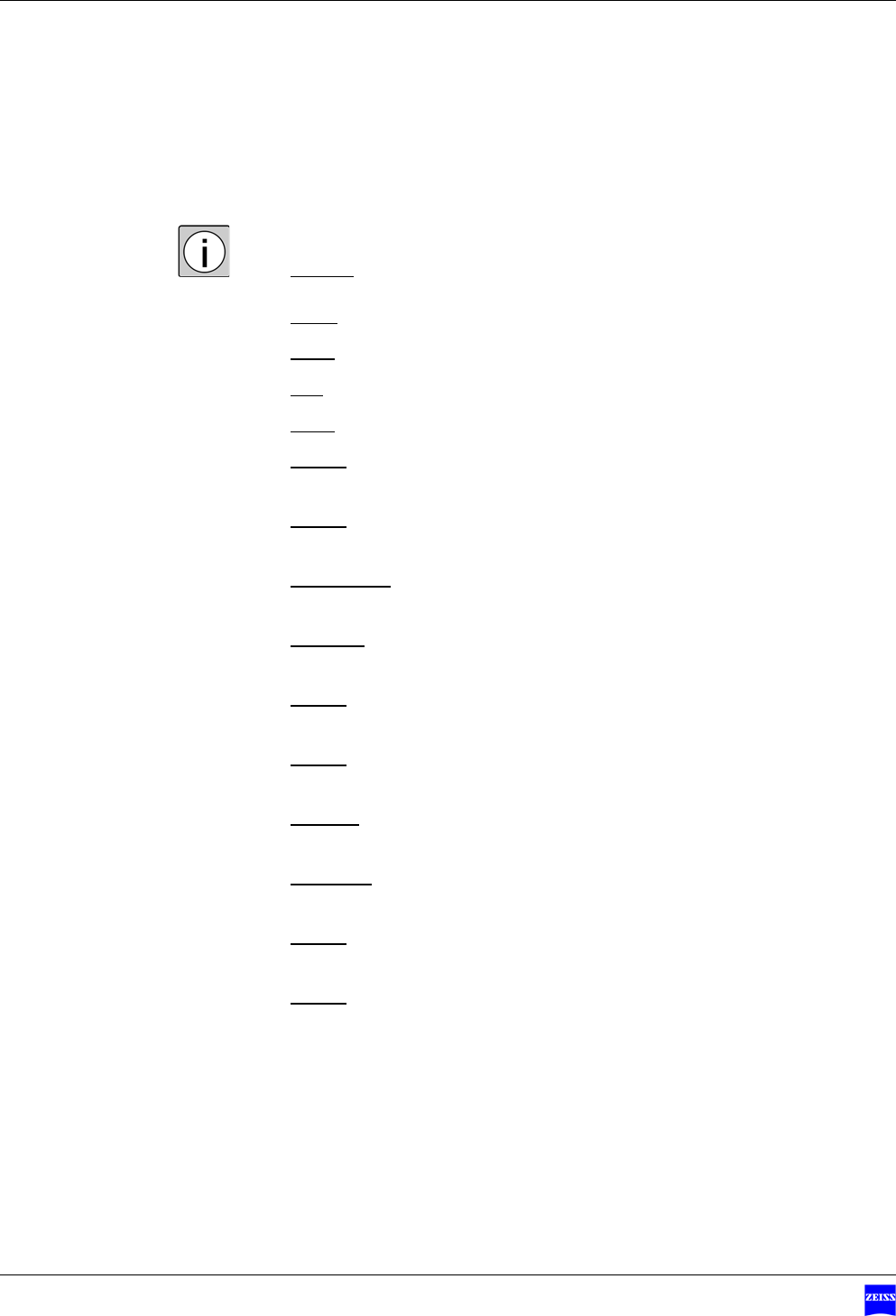
Standard assignment in the longitudinal configuration
The longitudinal configuration refers to the focus and zoom functions.
Joystick
The joystick permits control in the following four directions:
1front,
2back,
3left,
4right.
5Switch
Function depending on surgical microscope used
6Switch
Function depending on surgical microscope used
7Focus down
Focusing on a lower plane, the working distance is increased
8Focus up
Focusing on a higher plane, the working distance is reduced
9Switch
Function depending on surgical microscope used
10 Switch
Function depending on surgical microscope used
11 Zoom in
Increasing magnification, the field of view is reduced
12 Zoom out
Reducing magnification, the field of view is increased
13 Switch
Function depending on surgical microscope used
14 Switch
Function depending on surgical microscope used
Version 1.0
G-30-1707-en Page 27
Foot Control PanelFCP Interface & FCP WL Interface Standard assignment in the longitudinal configuration
6
7
8
11
12
13
14 5
10 9
1
2
43

Design and function Foot Control Panel FCP Interface & FCP WL Interface
Version 1.0
Page 28 G-30-1707-en
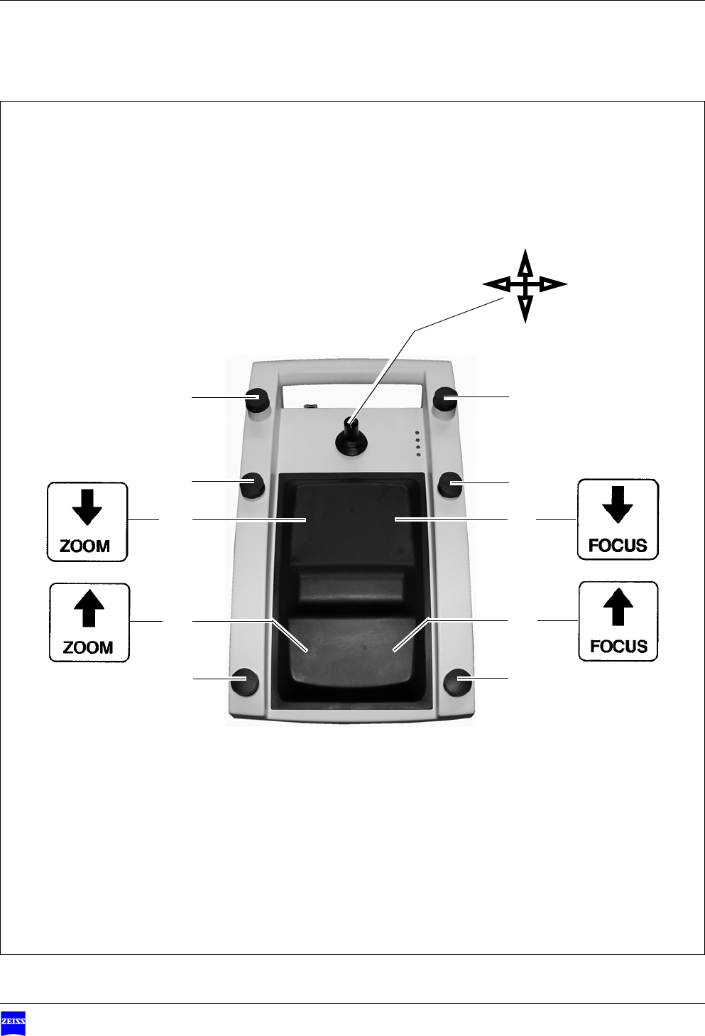
Standard assignment in the transverse configuration
The transverse configuration refers to the focus and zoom functions.
Joystick
The joystick permits control in the following four directions:
1front,
2back,
3left,
4right.
5Switch,
Function depending on surgical microscope used
6Switch
Function depending on surgical microscope used
7Focus down
Focusing on a lower plane, the working distance is increased
8Focus up
Focusing on a higher plane, the working distance is reduced
9Switch
Function depending on surgical microscope used
10 Zoom out
Reducing magnification, the field of view is increased
11 Zoom in
Increasing magnification, the field of view is reduced
12 Switch
Function depending on surgical microscope used
13 Switch
Function depending on surgical microscope used
14 Switch
Function depending on surgical microscope used
Version 1.0
G-30-1707-en Page 29
Foot Control PanelFCP Interface & FCP WL Interface Standard assignment in the transverse configuration
1
6
7
9
12
8
13
14 5
11 10
2
43
Design and function Foot Control Panel FCP Interface & FCP WL Interface
Version 1.0
Page 30 G-30-1707-en
Upgrade module
Components of the upgrade module
1Connection cable socket
Connection of the foot control panel via a connection cable
2Orientation switch
Defines the orientation of the focus and zoom functions in the longitu-
dinal or transverse direction
3"Ready for use" status indicator
– Shining green: the foot control panel is ready for use, no error is
present.
– Shining red: the foot control panel is not ready for use, an error is
present.
4Cable connection status indictor
– Shining: the connection cable has been connected, power supply is
present.
– Not shining: the foot control panel operates in the cordless mode.
5Radio link status indicator
– Shining green: very good radio link
– Shining yellow: reduced radio link, e.g. due to slight interference,
shielding or too large a distance between the suspension system and
foot control panel.
– Shining red: no radio link, e.g. due to non-existent pairing with the
suspension system, shielding or too large a distance between the sus-
pension system and foot control panel.
– Flashing yellow: while pairing with the suspension system is being per-
formed.
NOTE Upgradable surgical microscopes
•Surgical microscopes on the S7, S8, S81, S88, NC4 and NC33 sus-
pension systems as well as OPMI Pentero do not feature an integrat-
ed radio module. The radio module can be retrofitted.
• Other systems than those specified above cannot be upgraded.
3
4
5
6
Version 1.0
G-30-1707-en Page 31
Foot Control PanelFCP Interface & FCP WL Interface Upgrade module
6Battery status indicator
– Shining green: batteries are OK.
– Shining yellow: warning that batteries will not last much longer.
– Shining red: batteries are depleted and need to be replaced immedi-
ately.
7Pairing button
A press of this button, starts the pairing process between the foot control
panel and suspension system.
Pairing means the fixed relative assignment of the suspension system and
foot control panel.
1
2
7
3
4
5
6

Design and function Foot Control Panel FCP Interface & FCP WL Interface
Version 1.0
Page 32 G-30-1707-en

Version 1.0
G-30-1707-en Page 33
Foot Control PanelFCP Interface & FCP WL Interface
Preparations for use
Installing the upgrade module.........................................................34
Inserting the batteries for cordless operation..................................36
Pairing with the suspension system.................................................38
Connecting the connection cable.....................................................40
Exchanging the joystick head ..........................................................41
Bringing the foot control panel into its working position................42
Preparations for use Foot Control Panel FCP Interface & FCP WL Interface
Version 1.0
Page 34 G-30-1707-en
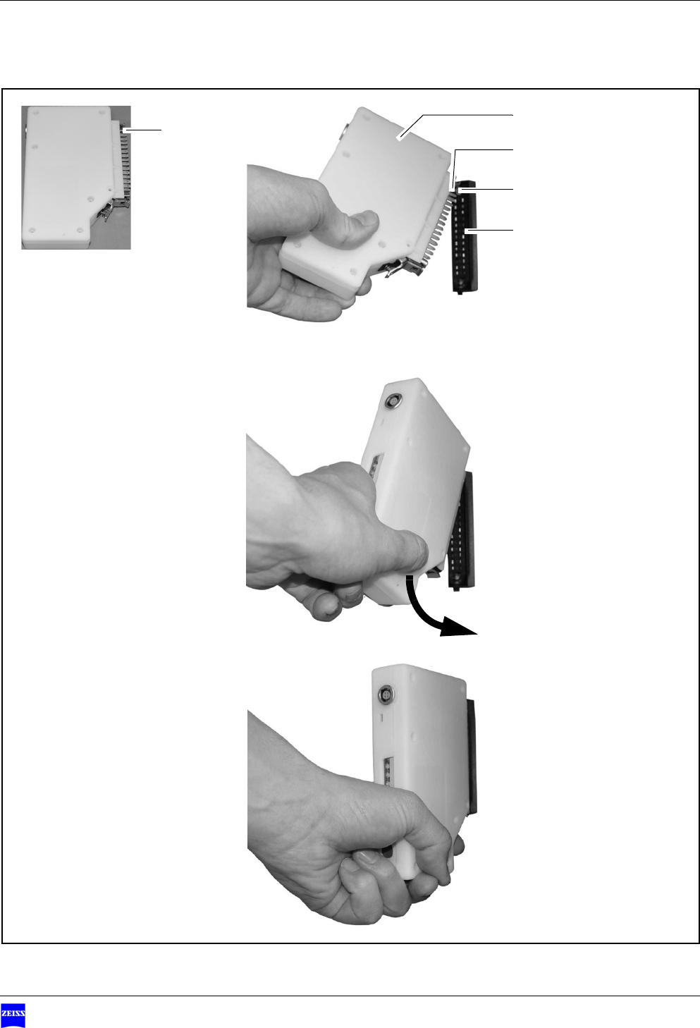
Installing the upgrade module
9The suspension system must feature a multi-point connector (4).
9The suspension system and surgical microscope must be powered down.
• Align head (1) with counterpart (3) on the multi-point connector.
• Push upgrade module (3) against the multi-point connector, see (5), until
you hear the upgrade module snap into position.
ÆThe upgrade module is now operational (6).
The functions of the foot control panel can be configured via the suspen-
sion system.
NOTE Upgradable surgical microscopes
•Surgical microscopes on the S7, S8, S81, S88, NC4 and NC33 sus-
pension systems as well as OPMI Pentero do not feature an integrat-
ed radio module. The radio module can be retrofitted.
• Other systems than those specified above cannot be upgraded.
Version 1.0
G-30-1707-en Page 35
Foot Control PanelFCP Interface & FCP WL Interface Installing the upgrade module
1
3
4
2
1
5
6

Preparations for use Foot Control Panel FCP Interface & FCP WL Interface
Version 1.0
Page 36 G-30-1707-en
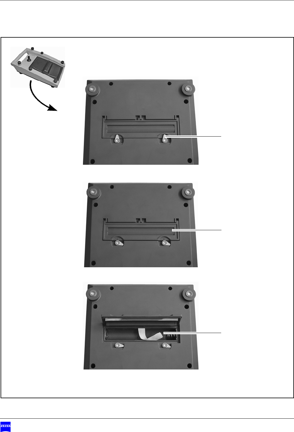
Inserting the batteries for cordless operation
• Turn the two locks (1) on the battery compartment from the 12 o'clock
position to the 3 o'clock position.
• Open the cover of the battery compartment (2).
• Insert three C type batteries in the battery compartment, ensuring that the
polarity is correct. The polarity is shown at the bottom of the battery com-
partment (3).
• Close the cover of the battery compartment (2).
• Turn the two locks (1) on the battery compartment from the 3 o'clock po-
sition back to the 12 o'clock position.
NOTE Risk of damaging the foot control panel by using wrong batteries
• The wrong type of batteries may damage the foot control panel or impair
its function.
• Only use C type 1.5 V alkaline-manganese batteries, also see the chapter
"Technical data".
• Do not use any rechargeable batteries. The operating duration with re-
chargeable batteries has not been defined.
Version 1.0
G-30-1707-en Page 37
Foot Control PanelFCP Interface & FCP WL Interface Inserting the batteries for cordless operation
1
2
3
Preparations for use Foot Control Panel FCP Interface & FCP WL Interface
Version 1.0
Page 38 G-30-1707-en
Pairing with the suspension system
Pairing means the fixed relative assignment of the suspension system and
foot control panel.
Pairing must be performed for cordless operation.
• Put the foot control panel in its rest position (1) in the immediate vicinity
of the suspension system (1).
• Start the pairing process on the suspension system or
press "Pairing" button (2) on the radio module.
Æ"Radio link" status indicator (3) on the radio module flashes yellow.
• Press one of the buttons (4) on the foot control panel for about 5 seconds.
Æ"Radio link" status indicator (3) on the radio module starts flashing.
• Release button (4) on the foot control panel.
Æ"Radio link" status indicator (3) continues flashing for a few seconds.
Pairing was successful
ÆA beep indicates that pairing has been successfully completed.
ÆThe "radio link" status indicator (3) shines green for about 1 second.
You can also check whether pairing was successful by simultaneously
pressing two buttons on the foot control panel. "Radio link" status indi-
cator (3) will be lit.
Pairing was not successful
ÆThree beeps indicate that pairing has not been successfully completed.
Æ"Radio link" status indicator (3) shines red for about 1 second.
Æ"Radio link" status indicator (3) on the radio module shines red.
NOTE The foot control panel may be disabled.
• If pairing is performed incorrectly or not at all, the foot control panel may
be disabled, or activation of a control may trigger functions on a different
suspension system not assigned to the foot control panel.
Version 1.0
G-30-1707-en Page 39
Foot Control PanelFCP Interface & FCP WL Interface Pairing with the suspension system
• Repeat the pairing process as described above.
NOTE Risk of confusion when using multiple foot control panels
• The use of several foot control panels may lead to confusion and, as a
result, to malfunction.
• After pairing, mark the associated suspension system with a number
(stickers provided in the delivery package) and set indicator (5) on the
foot control panel to the number assigned to the suspension system.
• Make sure that the assigned identification is unique in the entire opera-
tion area.
1
2
3
3
44
4
4
4
4
5
Preparations for use Foot Control Panel FCP Interface & FCP WL Interface
Version 1.0
Page 40 G-30-1707-en
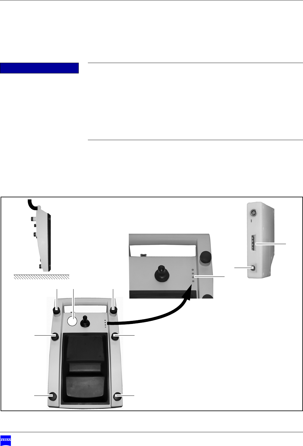
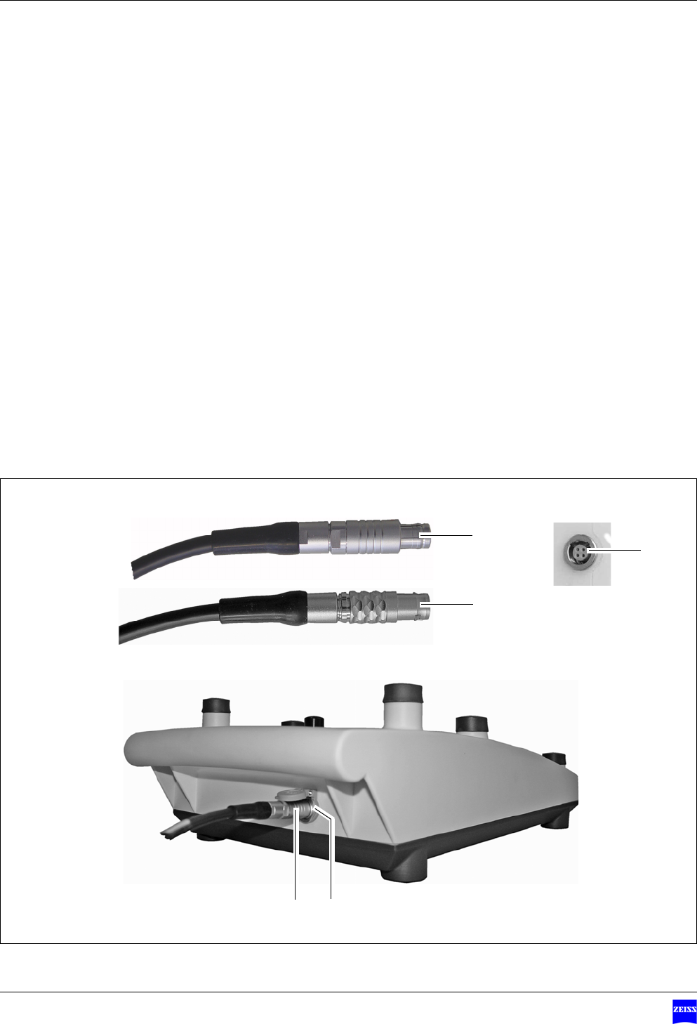
Connecting the connection cable
The connection cable is required for corded operation of the foot control
panel.
Only use
– Cable 304970-8730-000 with a 3 m length or
– Cable 304970-8760-000 with a 6 m length
• Insert 6-pin connector (1) in socket (3) on the foot control panel.
• Insert 4-pin connector (2) in socket (4) on the upgrade module.
1
3
2
1
4
Version 1.0
G-30-1707-en Page 41
Foot Control PanelFCP Interface & FCP WL Interface Exchanging the joystick head
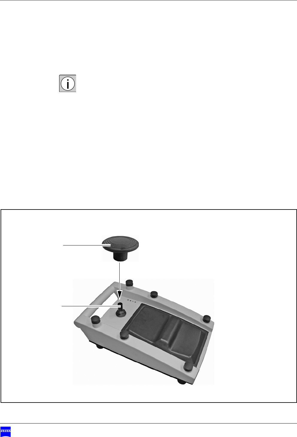
Exchanging the joystick head
The delivery package of the foot control panel includes an extension for the
joystick and a joystick knob. You can use these items to suit your personal
work style.
• Remove joystick extension (1) by pulling it upward.
• Push joystick knob (2) into position as far as it will go.
1
2
Preparations for use Foot Control Panel FCP Interface & FCP WL Interface
Version 1.0
Page 42 G-30-1707-en
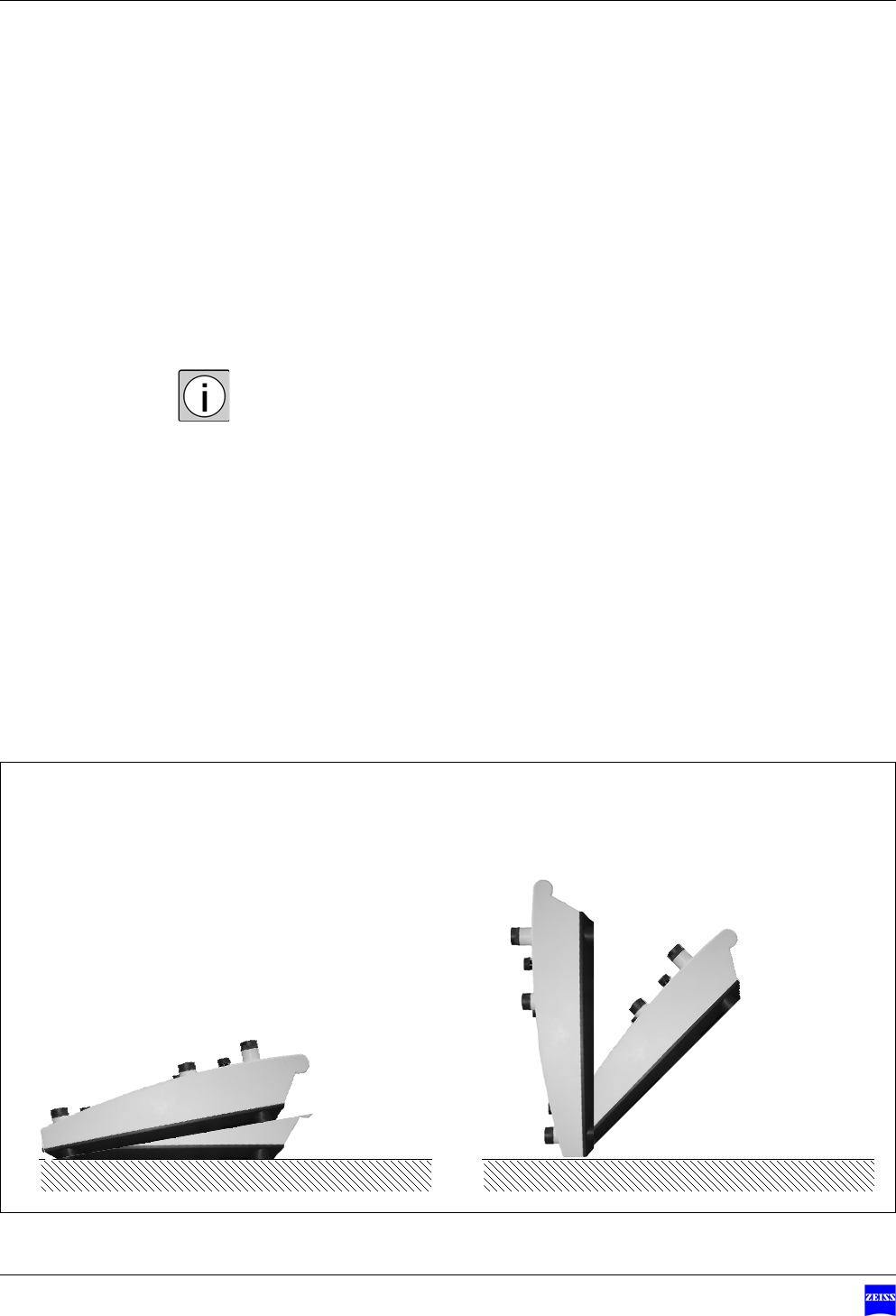
Bringing the foot control panel into its working position
• Bring the foot control panel into its working position (1).
– Working position: 0° ... 10°
– Rest position: 45 ° ... 90°
In its rest position (2), the foot control panel is completely disabled. It shuts
down to save energy.
12
0°
10°
90°
45°

Operation Foot Control Panel FCP Interface & FCP WL Interface
Version 1.0
Page 44 G-30-1707-en
Checklist
• Always check the function of the foot control panel before surgery (with-
out patient!) using the following checklist:
Prerequisites 9The foot control panel is in its working position.
9The batteries have been inserted with correct polarity.
9The suspension system has been powered on.
9The connection cable is undamaged and ready for operation.
9The foot control panel has been paired with the suspension system or the
connection cable has been connected to the upgrade module.
9The number in the indicator of the foot control panel is identical to that
on the suspension system.
9The freely programmable buttons have been configured.
9The foot control panel has been connected to the suspension system.
• Check all functions of the foot control panel.
ÆThe suspension system and the surgical microscope must perform the de-
fined functions.
CAUTION Failure of functions!
If a function fails, do not use the foot control panel for safety reasons.
• If possible, correct the malfunction (see "Troubleshooting“) or contact
the Zeiss service department.
Version 1.0
G-30-1707-en Page 45
Foot Control PanelFCP Interface & FCP WL Interface
What to do in the event of malfunctions
What to do in an emergency ...........................................................46
Failure of the cordless foot control panel...................................................46
Removing the upgrade module..................................................................47
Troubleshooting ..............................................................................48
For your safety ..........................................................................................48
Malfunction of the foot control panel........................................................48
What to do in the event of malfunctions Foot Control Panel FCP Interface & FCP WL Interface
Version 1.0
Page 46 G-30-1707-en
What to do in an emergency
Failure of the cordless foot control panel
The suspension system or the surgical microscope does not respond to the ac-
tivation of any of the controls on the foot control panel.
• Insert 6-pin connector (1) of the connection cable in socket (3) on the foot
control panel.
• Insert 4-pin connector (2) of the connection cable in socket (4) on the up-
grade module.
ÆThe foot control panel now operates in the corded mode.
1
3
2
1
4
Version 1.0
G-30-1707-en Page 47
Foot Control PanelFCP Interface & FCP WL Interface What to do in an emergency
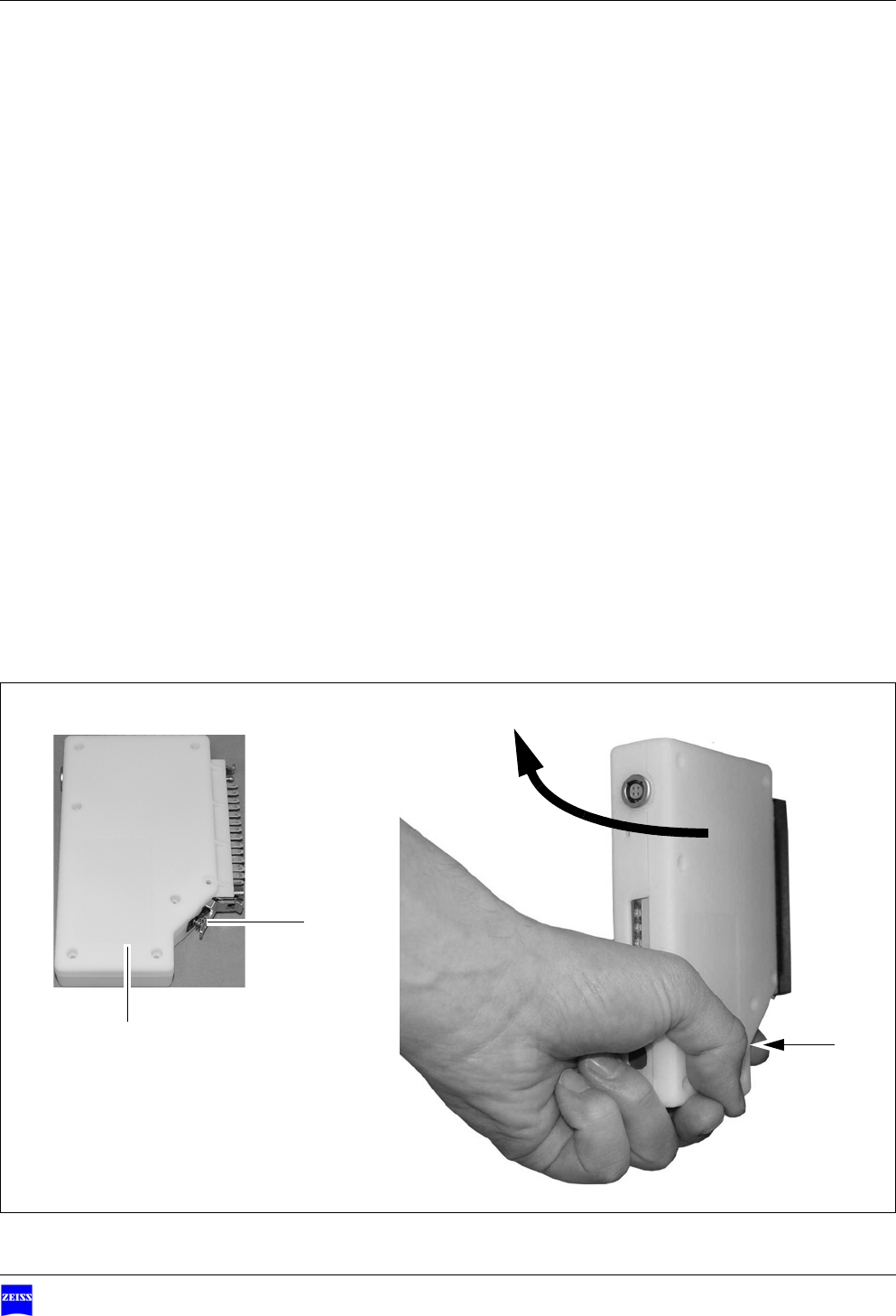
Removing the upgrade module
The triggered functions cannot be completed, the suspension system or the
surgical microscope does not stop moving.
• Press clip (1) on upgrade module (2).
• Pull off the upgrade module in an upward direction, see (3).
ÆThe foot control panel is disabled.
1
1
2
3
What to do in the event of malfunctions Foot Control Panel FCP Interface & FCP WL Interface
Version 1.0
Page 48 G-30-1707-en
Troubleshooting
For your safety
This device is a high-grade technological product. To ensure optimum per-
formance and safe working order, we recommend having it checked by our
service representative as part of regular scheduled maintenance.
• If a failure occurs which you cannot correct with the aid of the chapter
"What to do in the event of malfunctions“, attach a sign to the device stat-
ing it is out of order and contact our service representative.
Malfunction of the foot control panel
Problem Possible cause Remedy See
Foot control panel is inopera-
tive
Connection cable not con-
nected to suspension system
Connect via connection cable page 40
Limited performance during
operation
Batteries are depleted Replace batteries page 36
Use of rechargeable batteries Replace batteries page 36
Failure of individual button
functions
Contact service dept. --
Failure / malfunction of radio
link in cordless foot control
panel
Make connection via cable page 40
Position switch always de-
tects rest position
Make connection via cable page 40
Interference in radio link Make connection via cable page 40
Weak radio signal Make connection via cable page 40

Version 1.0
G-30-1707-en Page 49
Foot Control PanelFCP Interface & FCP WL Interface Troubleshooting
Unwanted mechanical move-
ments
Button got jammed after acti-
vation
Cordless: put foot control
panel in rest position
Corded: disconnect cable
Contact service dept.
page 15
page 40
Foot control panel sends in-
correct activation signal
Cordless: put foot control
panel in rest position
Cordless: remove radio
module from suspension
system
Corded: disconnect cable
page 15
Wrong foot control panel Check whether the identifica-
tions on the suspension
system and in the indicator of
the foot control panel are
identical.
--
Perform pairing with the sus-
pension system
page 38
Problem Possible cause Remedy See

What to do in the event of malfunctions Foot Control Panel FCP Interface & FCP WL Interface
Version 1.0
Page 50 G-30-1707-en

Version 1.0
G-30-1707-en Page 51
Foot Control PanelFCP Interface & FCP WL Interface
Care and maintenance
Care of the device............................................................................52
Cleaning....................................................................................................52
Disinfection ...............................................................................................52
Environmental protection measures ................................................53
Note on disposal .......................................................................................53
Care and maintenance Foot Control Panel FCP Interface & FCP WL Interface
Version 1.0
Page 52 G-30-1707-en
Care of the device
Cleaning
Contamination of the foot control panel
– If possible, clean the foot control panel and its components directly after
use.
– Contaminations should not be allowed to dry on the objects, as this would
make cleaning and disinfecting more difficult.
Cleaning mechanical surfaces
All mechanical surfaces of the foot control panel and its components can be
cleaned by wiping them with a damp cloth. Do not use any aggressive or abra-
sive cleaning agents.
Clean off any residue using a mixture of 50% ethyl alcohol and 50% distilled
water plus a dash of household dish-washing liquid.
Disinfection
It may be necessary to disinfect the foot control panel to permit its use in the
OR, for example.
We recommend using MELISEPTOL disinfectant from B. Braun, Melsungen
AG.
MELISEPTOL is available from Carl Zeiss, and you can also obtain it locally in
many countries from representatives of B. Braun, Melsungen AG.
CAUTION Observe the manufacturer's instructions for use.
– Use MELISEPTOL in accordance with the manufacturer's specifications
and observe the instructions for use provided with the product.
– Wear disposable plastic gloves to prevent skin contact with the disinfect-
ant.
Version 1.0
G-30-1707-en Page 53
Foot Control PanelFCP Interface & FCP WL Interface Environmental protection measures
Environmental protection measures
Note on disposal
User information
on the disposal of electrical and electronic devices
This symbol means that the product must not be disposed of as normal do-
mestic waste.
The correct disposal of electrical or electronic devices helps to protect the en-
vironment and to prevent potential hazards to the environment and/or human
health which may occur as a result of improper handling of the devices con-
cerned.
For detailed information on the disposal of the product, please contact your
local dealer or the device manufacturer or its legal successor. Please also note
the manufacturer's current information on the Internet. In the event of resale
of the product or its components, the seller is required to inform the buyer
that the product must be disposed of in accordance with the applicable na-
tional regulations currently in force.
For customers in the European Union
Please contact your dealer or supplier if you wish to dispose of electrical or
electronic devices.
Information on disposal in countries outside the European Union
This symbol is only applicable in the European Union. For the disposal of elec-
trical and electronic devices, please observe the relevant national legislation
and other regulations applicable in your country.
Care and maintenance Foot Control Panel FCP Interface & FCP WL Interface
Version 1.0
Page 54 G-30-1707-en
Disposal of batteries
Please observe the local directives relating to the disposal of batteries, or con-
tact your local sales organization for further information.
The batteries must no be disposed of as normal domestic waste. Use an ap-
propriate facility for the disposal of batteries.
WARNING Risk of explosion!
• Never throw batteries into a fire.

Version 1.0
G-30-1707-en Page 55
Foot Control PanelFCP Interface & FCP WL Interface
System data
Technical data .................................................................................56
Mechanical data ........................................................................................56
Electrical data............................................................................................56
Ordering data ..................................................................................58
Approval verification .......................................................................59
Ambient conditions .........................................................................60
System data Foot Control Panel FCP Interface & FCP WL Interface
Version 1.0
Page 56 G-30-1707-en
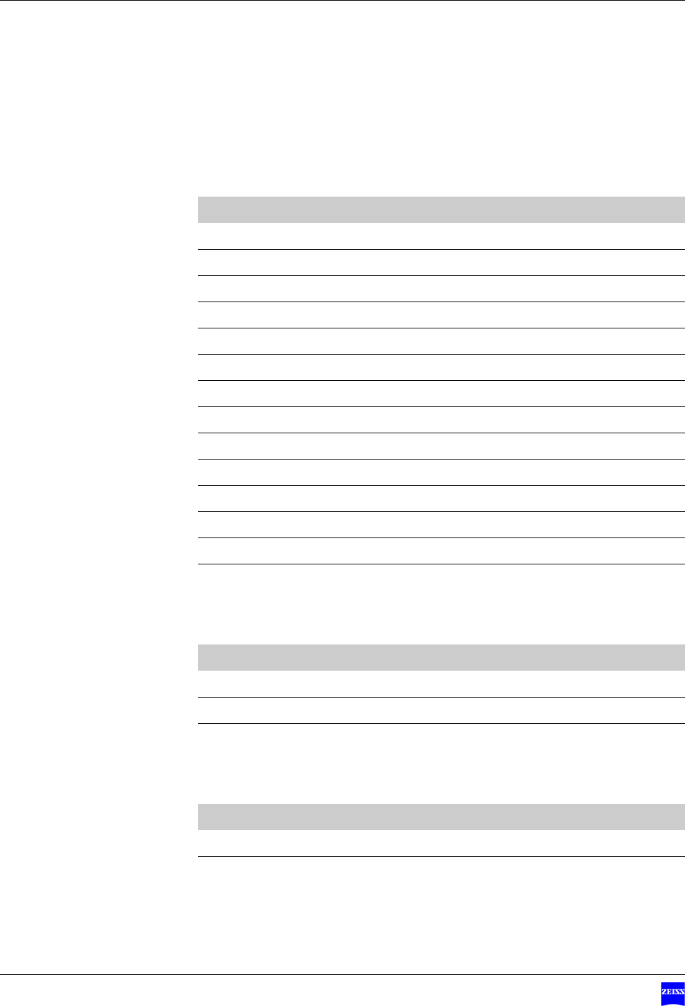
Technical data
Mechanical data
Electrical data
Electrical data, cordless operation
Component Feature
Dimensions L x W x H approx. 415 x 245 x 110 mm
Weight approx. 2.4 kg
Component Feature
Power supply 3 x C type 1.5 V alkaline-manganese batteries
Current consumption max. 100 mA
Service life of batteries approx. 2 - 6 months
Electrical standard Complying with IEC 60601-1; UL 60601-1;
Protection class I, degree of protection IPX8
Type B equipment
Cable connection Remote socket for CANbus cable
The device has been designed for continuous operation.
Version 1.0
G-30-1707-en Page 57
Foot Control PanelFCP Interface & FCP WL Interface Technical data
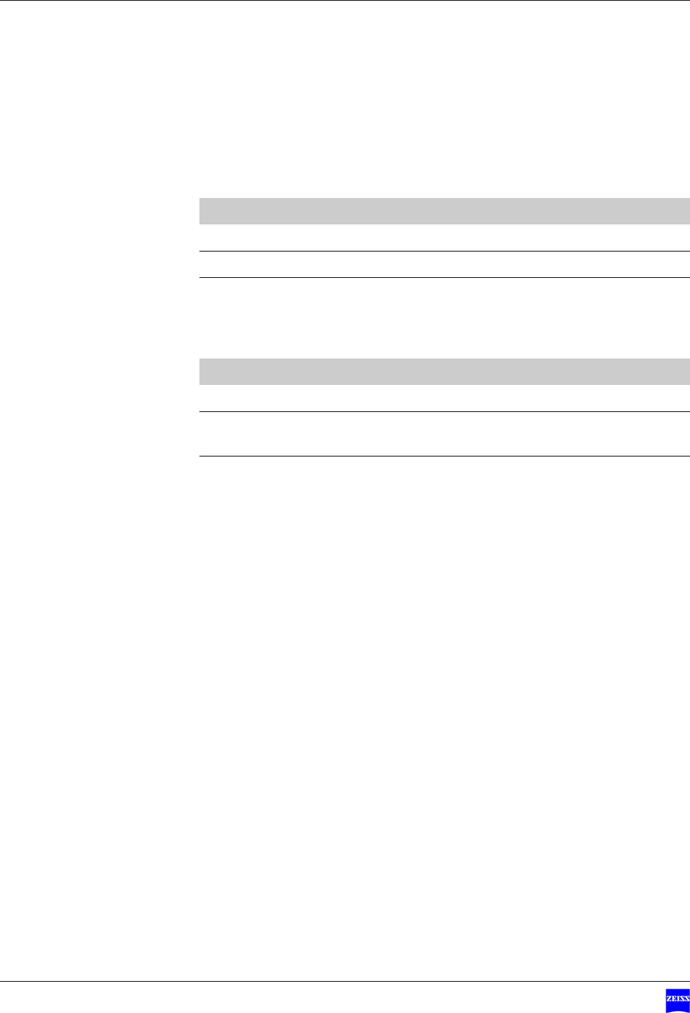
Electrical data, corded operation
Radio module
Component Feature
Power supply 15 VDC ±10 %
Power consumption max. 200 mA
Electrical standard Complying with IEC 60601-1; UL 60601-1;
Protection class I, degree of protection IPX8
Type B equipment
Cable connection Remote socket for CANbus cable
The device has been designed for continuous operation.
Component Feature
Transmission fre-
quency
2402 ... 2480 MHz
Receiving power -82 .... 0 dbm
Transmission power 0 dbm - max. 2.5 mW - Class 2
Approval Only in combination with the suspension systems
specified on page 30
System data Foot Control Panel FCP Interface & FCP WL Interface
Version 1.0
Page 58 G-30-1707-en
Ordering data
Foot control panel with 14 functions - cordless and corded
Disinfection - Meliseptol
Disposable gloves
Description Cat. No.
Foot control panel with 14 functions, corded 304970-9100-000
Foot control panel with 14 functions, cordless 304970-9200-000
Joystick knob 304970-8807-000
Joystick extension 304970-8808-000
3 C type 1.5 V alkaline-manganese batteries 000000-0035-244
CANbus cable, 3 m 304970-8730-000
CANbus cable, 6 m 304970-8760-000
Upgrade module, corded 304970-9300-000
Upgrade module, cordless 304970-9400-000
Upgrade kit, cordless, 14 functions 304970-9060-000
Upgrade kit, corded, 14 functions 304970-9070-000
Description Cat. No.
1 l MELISEPTOL in vario bottle 000000-0103-907
MELISEPTOL HBV spray, 250 ml 000000-0103-910
MELISEPTOL HBV cloths 000000-0103-911
Description Cat. No.
Size 1 (large) size 8-9 000000-0117-736
Size 2 (medium) size 7-8 000000-0117-737

Version 1.0
G-30-1707-en Page 59
Foot Control PanelFCP Interface & FCP WL Interface Approval verification
Approval verification
Description Identification
EMC requirements The foot control panel meets the EMC require-
ments in accordance with IEC 60601-1-2.
The system meets the RFI requirements of Class B.
FCC The foot control panel meets the requirements of
Part 15 of FCC
EG The foot control panel meets the requirements of
EC Directive 1999/5/EC
ARIB The foot control panel meets the requirements of
ARIB
System data Foot Control Panel FCP Interface & FCP WL Interface
Version 1.0
Page 60 G-30-1707-en
Ambient conditions
For operation
For transportation and storage
Feature Admissible range
Temperature + 10 °C ... + 40 °C
Rel. humidity 30 % ... 75 %
Air pressure 700 hPa ... 1060 hPh
Feature Admissible range
Temperature - 25 °C ... + 70 °C
Rel. humidity (without
condensation)
10 % ... 90 %
Air pressure 500 hPa ... 1060 hPh

Foot Control PanelFCP Interface & FCP WL Interface
Version 1.0
G-30-1707-en Page 61
Index
A
Acoustic signal .........................................................................................25
Approval verification .................................................................................59
B
Batteries, depleted ....................................................................................48
Batteries, disposal .....................................................................................54
Batteries, inserting ....................................................................................36
Batteries, service life .................................................................................56
Battery compartment ................................................................................36
Battery type ..............................................................................................36
Bracket .....................................................................................................22
C
Checklist ...................................................................................................44
Cleaning ...................................................................................................52
Connection cable ......................................................................................22
Connection cable not connected ..............................................................48
Controls ...................................................................................................22
Current consumption ................................................................................56
E
Electrical standard ....................................................................................56
Electromagnetic compatibility ...................................................................10
Electromagnetic interference ....................................................................10
EMC requirements of IEC 60601-1-2 ........................................................10
F
Failure of a function .................................................................................44
Failure of the cordless foot control panel ..................................................46
Foot rest ...................................................................................................22
I
Indicator .............................................................................................22, 39
Intended use ..............................................................................................8

Index Foot Control Panel FCP Interface & FCP WL Interface
Version 1.0
Page 62 G-30-1707-en
J
Joystick ...............................................................................................22, 41
L
Labels on the foot control panel ...............................................................16
Limit class .................................................................................................10
Longitudinal configuration ..................................................................22, 26
M
Malfunction when using multiple foot control panels ................................39
N
Notes on EMC ..........................................................................................10
P
Pairing ................................................................................................31, 38
Power supply ............................................................................................56
Problem ....................................................................................................48
R
Radio frequency radiation in acc. with FCC ...............................................10
Radio link ..................................................................................................48
Radio module, removing ...........................................................................47
Radio signal ..............................................................................................48
Rest position .......................................................................................15, 42
Rocker switch ...........................................................................................22
S
Safety .........................................................................................................7
Safety standards .........................................................................................7
Status indicators .................................................................................22, 24
T
Target group ...............................................................................................8
Technical data ..........................................................................................56
Transverse configuration .....................................................................22, 28
U
Upgradable surgical microscope .........................................................30, 34
Upgrade module .................................................................................30, 34


Index Foot Control Panel FCP Interface & FCP WL Interface
Version 1.0
Page 64 G-30-1707-en

Version 1.0
G-30-1707-en Page 65
Foot Control PanelFCP Interface & FCP WL Interface
(Blank page, for your notes . . .)

Carl Zeiss Surgical GmbH
A Carl Zeiss Meditec Company
73446 Oberkochen
Germany
Fax.: + 49 (0)7364 - 20 4823
Email: surgical@meditec.zeiss.com
Internet: www.meditec.zeiss.com