Carlson Wireless Technologies FT-512 FT-512 Trailblazer Multifunctional Digital Radio User Manual 291830
Carlson Wireless Technologies Inc FT-512 Trailblazer Multifunctional Digital Radio 291830
UserManual.wiki
>
Carlson Wireless Technologies
>
FT 512 User Manual
User Manual
Navigation menu
Upload a User Manual
Namespaces
Wiki Guide
HTML
PDF
Info
Views
User Manual
Discussion / Help
Navigation
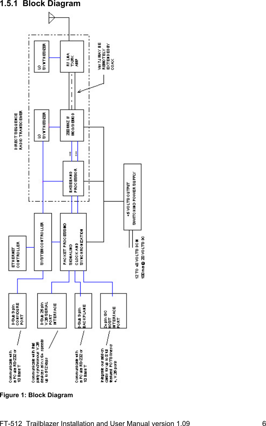
![FT-512 Trailblazer Installation and User Manual version 1.09 19 3 Operation 3.1 Configuration with the Graphic User Interface 3.1.1 Overview The FT-512 GUI Optimizer software allows you to configure, test and monitor Trailblazer products easily through familiar setup screens. There are several screens that serve as input/output graphical representations of a more complicated Command Line script language. Operating parameters of the FT-512 boards are stored in Flash EEPROM onboard, simplifying manufacturing and field configuration. 3.1.2 Installation of FT-512 GUI CD in a computer The GUI software is provided on a CD-ROM disc. It may be installed on any Microsoft Windows 9x/ME/NT/2000/XP equipped PC with an available RS-232 serial communications (COM) port. The screen resolution must be at least 800 x 600 (SVGA). The following describes the installation: • Insert the CD-ROM disk. If the installation doesn’t begin immediately you will have to double click the [CD drive letter]:\setup.exe file through the StartÆ Run Æ Browse to CD drive and then double click on setup.exe. • Accept all of the default choices presented to you by the installation software. • See our web site to insure you have the latest software release. • Don’t execute the installed software until connecting the cable link as described below. 3.1.3 Communications with the FT-512 and a computer You will need a standard PC running Windows 9x, ME, NT4, 2000 or XP with a spare asynchronous serial Communications (COM) port numbered 1 through 4. A Serial Communications (SC) Cable is supplied with your system. This cable is a transmit/receive and CTS/RTS cross pair, DB9 female to a DB9 male. If this cable is lost or should need to be replaced for any reason, see the Appendix for configuration port pin-outs to describe its makeup.](https://usermanual.wiki/Carlson-Wireless-Technologies/FT-512/User-Guide-291830-Page-31.png)