Carlson Wireless Technologies I-WLL Wireless Local Loop Extender (Digital Remote Phone User Manual i WLL Manual
Carlson Wireless Technologies Inc Wireless Local Loop Extender (Digital Remote Phone i WLL Manual
Operation Manual
Carlson Wireless USA revision 1.05 Page 20
CARLSON WIRELESS TELEPHONE, Inc.
CARLSON WIRELESS USA
USA Headquarters:
1150 Evergreen Road
P.O. Box 2400
Redway, CA 95560 USA
Tel: +1 707 923 9593
Fax: +1 707 923 1913
Email sales@wireless-telephone.com
DISTRIBUTED BY:
Publication date – Oct 99
About Carlson Wireless Telephone Inc.
Carlson Wireless Telephone, Inc. was formed in March 1999 as
a privately held corporation based in Redway, California. Carlson
Wireless Telephone (CWT) is dedicated to designing, manufac-
turing and marketing state-of-the-art digital WLL (wireless local
loop) telephone systems that provide high-quality voice and data
for rural and remote telephone users worldwide.
CWT was founded by James Carlson following a 15-month prod-
uct development by a team of engineers at Carlson Engineering
Services (CES), a private engineering design firm. In 1999 CWT
purchased the rights to the digital wireless telephone system de-
signed by CES. CWT will market and manufacture the product,
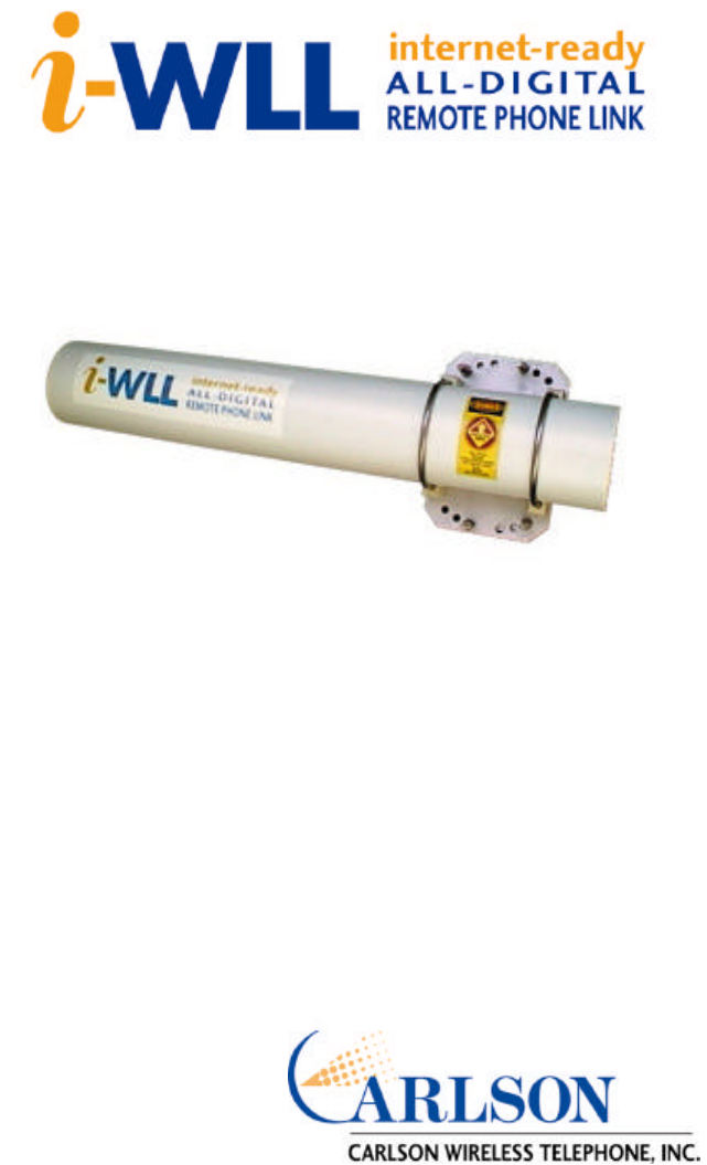
which has been named "The i-WLL Internet-Ready, All-Digital
Wireless Remote Telephone Link."
CWT is marketing the i-WLL product through established tele-
com and wireless equipment distributors. Please contact our
sales department +1 707 923 9593, or sales@wireless-
telephone.com for more information.
Carlson Wireless USA revision 1.05 Page 1
INSTALLATION & OPERATING MANUAL
MODEL NO. i-WLL-15
Caution! - Please read the sections on Un-
packing, Planning, and Installation before
installing this equipment

Carlson Wireless USA revision 1.05 Page 2
i-WLL, the i-WLL logo , Carlson Wireless USA, and the Carlson Wire-
less logo are registered trademarks of Carlson Wireless Telephone Inc.
Any trademarks, trade names, service marks, or service names owned
or registered by any other company and used in this manual are the
property of their respective companies. Copyright 1999, Carlson Wire-
less Telephone Inc. All rights reserved.
The employees and shareholders of Carlson Wireless Telephone Inc.
wish to thank you for your purchase of the i-WLL product. For more in-
formation about the company, see our web site at http://www.wireless-
telephone.com
Carlson Wireless USA revision 1.05 Page 19
(This page is intentionally left blank.)

Carlson Wireless USA revision 1.05 Page 18
Carlson Wireless USA Limited Warranty
Carlson Wireless Telephone (CWT) or Carlson Wireless USA, Collectively
referred to as "Carlson“) will repair this product with new or rebuilt parts,
free of charge, in the USA or Puerto Rico for two (2) years from the date of
original purchase in the event of a defect in material or workmanship. Mail-
in service in the USA can be obtained during the warranty period from a
Carlson Factory Service center by calling +1-707-923 9593, for a RMA
(Return Materials Authorization) number and mail your product adequately
packed, postage paid and insured to the address provided. This warranty is
extended only to the original purchaser. A purchase receipt or other proof of
date of original purchase will be required before warranty performance is
rendered. This warranty only covers failures due to defects in materials or
workmanship which occur during normal use. It does not cover damage
which occurs in shipment or failures which are caused by products not sup-
plied by Carlson or failures which result from accident, misuse, abuse, ne-
glect, mishandling, misapplication, alteration. modification, lightning, line
power surge, introduction of sand, dust, humidity and liquids or commercial
use of the product, or service by anyone other than a Carlson Factory Serv-
ice center or authorized Carlson Service center, or damage that is attribut-
able to acts of God.
Limits and Exclusions
There are no express warranties except as listed above.
CARLSON SHALL NOT BE LIABLE FOR INCIDENTAL OR CONSEQUEN-
TIAL DAMAGES RESULTING FROM THE USE OF THIS PRODUCT, OR
ARISING OUT OF ANY BREACH OF THIS WARRANTY. ALL EXPRESS
AND IMPLIED WARRANTIES, INCLUDING THE WARRANTIES OF MER-
CHANTABILITY AND FITNESS FOR A PARTICULAR PURPOSE, ARE
LIMITED TO THE APPLICABLE WARRANTY PERIOD SET FORTH
ABOVE.
Some states do not allow the exclusion or limitation of incidental or conse-
quential damages, or limitations on how long an implied warranty lasts, so
the above exclusions or limitations may not apply to you. This warranty
gives you specific legal rights and you may also have other rights which
vary from state to state. If a problem with this product develops during or
after the warranty period you may contact your dealer or Service center. If
the problem is not handled to your satisfaction, fax, phone, or write the
company at the address indicated in the service section of this manual.
Carlson Wireless USA revision 1.05 Page 3
TABLE OF CONTENTS
SCOPE OF MANUAL 4
UNPACKING 4
PRODUCT OVERVIEW 4
SYSTEM PLANNING 6
INSTALLATION 8
TROUBLESHOOTING 11
SPECIFICATIONS 12
PARTS LIST 14
CUSTOMER INFORMATION 16
WARRANTY 18

Carlson Wireless USA revision 1.05 Page 4
UNPACKING
The i-WLL-15 system will arrive in one box approximately 32 x 16x 9 inches
(80 x 40 x 23 cm). Small amounts of feed cable and power supplies may also
be included in this box if ordered.
Caution!
1. There are 2 large U-bolts holding the outer housing to the mounting plate of
each system. The fasteners on these are self locking nuts. DO NOT TURN
OR ROTATE THESE NUTS. They are set to a specific torque and if over-
torqued the housing will distort potentially damaging the electronic modules
inside.
2. DO NOT REMOVE THE FRONT END CAP. The seal is not lubricated for
removal and reinstallation. All of the electronics and antenna assembly are
serviced though the rear (mount-side) end cap.
SCOPE OF MANUAL
This manual is designed to support the installation, operation and mainte-
nance of the i-WLL–15 All-Digital Remote Wireless Telephone Link. To avoid
harm to persons or damage to the product please ensure that you have read
through the unpacking and installation sections before proceeding.
PRODUCT OVERVIEW
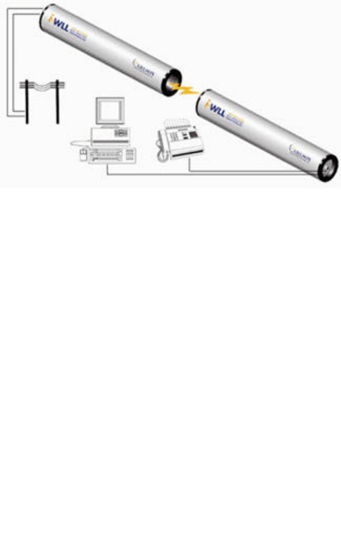
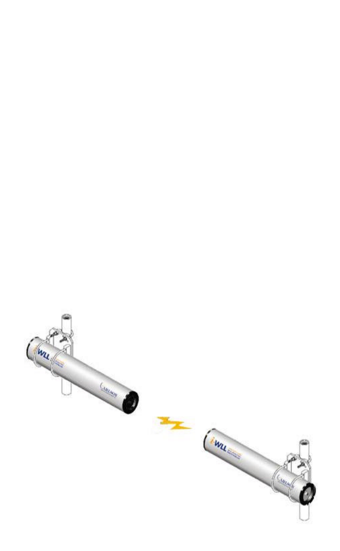
The i-WLL All-Digital, Internet-Ready, Remote Phone Link is a dual line,
point-to-point, spread spectrum telephone system that delivers v.34 data
rates, providing email and the Internet to your remote PC - as well as high-
quality voice! And both lines are fully independent and will transmit either
voice or data.
Carlson Wireless USA revision 1.05 Page 17
Radio interference
Carlson Wireless USA Model: i-WLL-15
This device complies with Part 15 of the FCC Rules. Operation is subject to
the following two conditions: (1) This device may not cause harmful interfer-
ence, and (2) This device must accept any interference received, including
interference that may cause undesired operation. Changes of modification not
expressly approved by the party responsible for compliance could void the
user’s authority to operate the equipment.
Notification to the telephone company cont’d
The REN is useful to determine the quantity of devices you may connect to
your telephone line and still have all of those devices ring when you telephone
number is called. In most, but not all, areas, the sum of the REN’s of all de-
vices connected to one line should not exceed five (5.0).
To be certain of the number of devices you may connect to your telephone
line , as determined by the REN, you should call your local telephone com-
pany to determine the maximum REN for your calling area.
Jack Types Needed
Connection to the telephone network should be made by using standard
modular telephone jack types (USOC) RJ11C or RJ11W.
Incidence of Harm
If your telephone equipment cause harm to the telephone network, the tele-
phone company may disconnect your service temporarily. If possible, they
will notify you in advance. But if advance notice is not practical, you will be
notified as soon as possible. You will be informed of your right to file a com-
pliant with the FCC.
Rights of the Telephone Company
Your telephone company may make change in it’s facilities, equipment, op-
erations or procedures that could affect the proper functioning of your equip-
ment. If they do, you will be notified in advance to give you an opportunity to
maintain uninterrupted telephone service.
Coin Service or Party Use Line
This equipment may not be used on the coin service provided by the tele-
phone company. Connection to party lines is subject to state tariffs.
Carlson Wireless USA revision 1.05 Page 16
Consumer and US Regulatory Information
Connection to the telephone network
1. The Federal Communications Commission (FCC) has established rules
which permits this device to be directly connected to the telephone network.
2. If this device is malfunctioning, it may also be causing harm to the tele-
phone network; this device should be disconnected until the source of the
problem can be determined and until repair has been made. If this is not
done, the telephone company may temporarily disconnect service.
3. The telephone company may make changes in its technical operations
and procedures; if such changes affect the compatibility or use of this device,
the telephone company is required to give adequate notice of the changes.
4. If the telephone company requests information on what equipment is con-
nected to their lines, inform them of:
(a) The telephone number that the unit is connected to
(b) The ringer equivalence number
(c) The USOC jack required
(d) The FCC Registration number
Item (b) and (c) are indicated on the label.
5. In the event of equipment malfunction, all repairs should be performed by
our company or an authorized agent. It is the responsibility of users requiring
services to report the need for service to our company or to one of our author-
ized agents.
Service can be obtained at: Carlson Wireless Telephone Inc.,
1150 Evergreen Road
P.O. Box 2400,
Redway, CA 95560 USA,
Tel: +1 707 923 9593
FCC Reg No., Part 68 BMD USA – 27773-PT-E
Notification to the telephone company
The equipment complies with Part 68 of the FCC rules. You will find the label
located on the device. This label contains the FCC Registration Number and
the Ringer Equivalence Number ((REN) for this equipment. You must, upon
request, provide this information to your telephone company.
Carlson Wireless USA revision 1.05 Page 5
The i-WLL breakthrough offers many advantages not found in the market to-
day:
•Never needs tuning because i-WLL is a 100% digital, self-configuring,
eight channel system. This simplifies installation and greatly reduces the
need for maintenance and service over time.
•Complete privacy is assured by the fully encrypted, spread-spectrum
modulation scheme.
•Highly efficient spectrum use from a unique combination of FDMA and
CDMA.
•Seamless integration with the global telephone network assured by i-
WLL’s worldwide ISDN system architecture with full 144 kbps bandwidth.
•No individual license needed for operation - i-WLL uses the globally li-
cense-free 2.4 GHz ISM frequency band.
•Flexible voltage – low power usage - just 3 to 6 Watts at any DC voltage
between 12 and 55V.
•Small, lightweight, self-contained units make i-WLL easy to install - no
special expertise needed. i-WLL FXO (central office) and FXS
(subscriber) units - which include all electronics, antenna and RF ca-
bling - are housed in a weatherproof enclosure 4.5" in diameter by 30"
long (11.5 x 76.2 cm) .

Carlson Wireless USA revision 1.05 Page 6
SYSTEM PLANNING
Certain requirements are necessary for the i-WLL-15 system to function.
(1) A radio path with losses fitting within the capacity of the system.
We have a chart showing various antenna and distance combinations.
What’s an acceptable “Link Margin“? An accepted theory is that 10 dB of
fade margin will deliver a 90% reliability and 20 dB will deliver a 99% reliability
etc.. There are other factors that affect this including vertical or horizontal po-
larization. At 2.4 GHz there is only a small ground wave component involved
in the radio propagation. This means that the above numbers are presuming
clear LOS (line of sight). Multi-path occurs when a reflector such as earth’s
terrain or man made structures cause additional delayed signals to be re-
ceived. If a signal was delayed 180 degrees out of phase with the line of sight
signal, and the magnitudes are the same, they will cancel out completely! In
the real world, if you do have line of sight path, multi-path degradation is the
reason why you need a minimum of 6 to 10 dB of margin. If you don’t have
line of sight, multi-path could easily cause 20 dB of degradation.
Distance Distance Model Path Loss ERP Link Margin
in Miles in km in dB in dBm
1.5 2.4 I-WLL-15 108 27 27
2.0 3.2 I-WLL-15 110 27 25
5.0 8.0 I-WLL-15 118 27 17
7.0 11.3 I-WLL-15 121 27 14
8.0 12.9 I-WLL-15 122 27 13
8.0 12.9 I-WLL-25 122 29 17
10.0 16.1 I-WLL-15 124 27 11
10.0 16.1 I-WLL-25 124 29 15
12.0 19.3 I-WLL-25 126 29 13
15.0 24.1 I-WLL-25 128 29 11
20.0 32.2 I-WLL-35 130 36 24
25.0 40.2 I-WLL-35 132 36 22
50.0 80.5 I-WLL-35 138 36 16
Fade Margin Chart
Carlson Wireless USA revision 1.05 Page 15
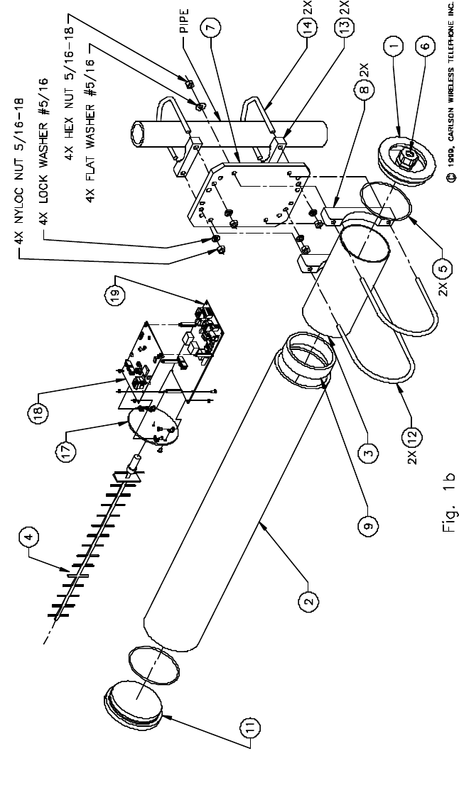
PARTS LIST i-WLL-15
PART-REV # DESCRIPTION
19 – L PCB, LINE INTERFACE & POWER REGULATOR
18 – S PCB, DIGITAL TOP
17 – B MOUNT, FRONT ANTENNA
16 – (RESERVED)
15 – (RESERVED)
14 – G U-BOLT, 2-3/4 INCH
13 – E CLAMP BASE, 2 3/4 INCH
12 – B U-BOLT, 4-1/2 INCH
11 – C END CAP, FRONT
10 – (RESERVED)
09 – A RING, RETAINING
08 – G BRACKET, SADDLE
07 – G PLATE, MOUNTING
06 – B GRIP, CABLE & SEALING GLAND
05 – C O-RING 1/8 x 3.50 x 3.75
04 – B ANTENNA, 16 ELEMENT 13.5 dB GAIN
03 – D SHIELD, INNER SS
02 – D HOUSING, OUTER
01 – E END CAP, REAR

Carlson Wireless USA revision 1.05 Page 14 Carlson Wireless USA revision 1.05 Page 7
(2) Other users of the 2.400 to 2.483 GHz ISM band.
The ISM or Industrial, Scientific, and Medical band, is shared with many other
type of services. Fortunately most of the users are located in urban areas,
leaving sharing concerns down to consumer microwave ovens and other
spread spectrum rural telephone users. The I-WLL-15 system has divided the
ISM band into 8 sub-bands or channels. One channel is used for system ad-
ministration with the system then randomly selecting 1 of the 7 remaining
channels for operation. The functionality of the i-WLL–15 system de-
pends on the existing and forecasted spectrum usage in the radio
path. Due to the characteristics of the spread spectrum radio, the ITU
(International Telecommunication Union) was able to coordinate this band
globally for unlicensed use. This means that any user has to accept all other
users in this band, interfering or not.
(3) Availability of telephone service and power.
The I-WLL-15 system consists of two units. One is designed to connect to
the standard phone lines provided by a local telephone company office (FXO
side) and the other connects to the telephone instruments such as; DTMF
(touch tone) telephones, fax machines, and computer modems (FXS side) via
individually twisted pair phone/data cable. The system is very flexible about
voltage requirements. 12 to 55 Volts DC with the current being inversely pro-
portional to the voltage, the power use being approximately 3 Watts for the
FXO side, in any state, and 3 to 6 Watts for the FXS side depending on us-
age state. We recommend over-sizing the supply by 1.5 to 2 times. Depend-
ing on the length, most installations can use 4 twisted pair, #22 AWG feed
cable. This will drop about 1 volt per 100 feet of length. To allow for most any
voltage drop situation we recommend 24 volt, 500 mA power supplies. Using
non-twisted IW or Quad phone wiring will result in cross-talk between
lines.
(4) Mounting structure.
Warning! Use extreme caution to avoid contact with any high voltage
power lines when constructing antenna structures!
The enclosure is designed to mount on a steel vertical pipe, commonly known
in North America as 1 to 2 inch pipe ( 2.5 to 5 cm ), with an actual outside
diameter of 1.3 to 2.5 inches ( 3 to 6 cm ). This mast must not move signifi-
cantly in any anticipated wind and must be connected with a short copper #8
AWG wire to a copper clad ground rod driven at least 6 feet (2m) into moist
earth.
Carlson Wireless USA revision 1.05 Page 8
INSTALLATION
Note that the installation of the FXO and FSO units are similar
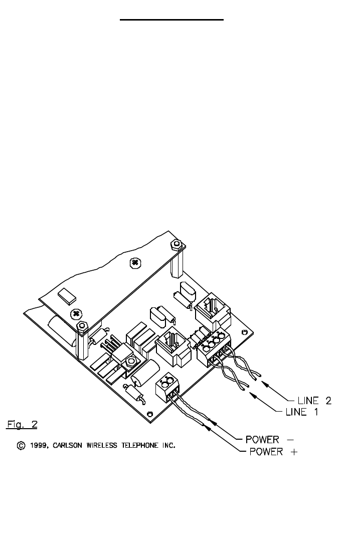
(1) Connecting the feed cable to the outside unit. On the mounting end of
the tube there is an end cap with a weather sealing clamp. This allows the
feed cable the penetrate the housing and remain sealed to outside weather.
Begin with the removal of the rear end cap by using a coin as a wedge and
working your way around the tube until the end cap pops off. Inside the end is
the electronics assembly consisting of the printed circuit boards and inte-
grated antenna. There are two screw down terminal blocks on the exposed
end. One block has 2 connections and it is where the DC power supply con-
nects. The other block has 4 connections, for telephone lines 1 and 2. The
following diagram shows how to wire the connectors. Make sure to hand
tighten only the weather sealing cord grip.
Note: Make sure that the antenna elements are vertical or perpen-
TIMESAVER TIP! By installing the FXO unit first, you can test the sys-
tem locally by temporarily connecting the FXS unit up at the FXO site and
proving your connections. This can greatly simplify any trouble shooting you
may have later.
Carlson Wireless USA revision 1.05 Page 13
POWER REQUIREMENTS & CONSUMPTION
Filtered DC 12 to 48 volts
Absolute Maximum / Minimum 10 to 55 volts
Sub End, On-Hook 3 Watts max
Sub End, 2 Lines Off-Hook 6 Watts max
Base End - On or Off-Hook 3 Watts max
RF PERFORMANCE
Frequency Range 2400 to 2483.5 MHz
RF Channels 7+1 (admin)
Spreading Method Direct Sequence
Modulation BPSK
PN Bit Length 16
Processing Gain 12.04 dB
ERP (Effective Radiated Power) +28.5 dBm
Receive Sensitivity -93 dBm @10-6 BER
System Range 10 miles (16.1 km)
PHYSICAL & ENVIRONMENTAL SPECIFICATIONS
Enclosure Material ABS weather sealed plastic
Dimensions ( inches) 4 1/2 diameter x 30 in length
Dimensions (cm) 11 diameter x 76 in length
Shipping Weight (system complete) 24 lbs (11 kg)
Operating Temp -30 to +65 degrees C
Humidity 10 to 95% non-condensing
Shock and Vibration Mil standard 810 D
Exposure to the Elements Nema 4X, all except submerged
WARRANTY 2 years parts and labor - see detail
CERTIFICATIONS AND REGULATORY
FCC Reg No., Part 68 BMD USA – 27773-PT-E
FCC Reg No., Part 15 OPA-I-WLL, Pending Final
Industry Canada CS-03 3448-10241A
Industry Canada RSS-210 Pending Final
Carlson Wireless USA revision 1.05 Page 12
SPECIFICATIONS
BASEBAND PERFORMANCE
Voice Coding Uncompressed 64 kb/s PCM
Signaling DTMF is passed through
Modem Support up to V.34-1996, (33.6 kb/s)
Fax Support up to G4, unrestricted
Digital Interface Asynchronous, RS-232, DCE
Idle Channel Noise -68 dBm max (20 dBrnCo)
End-to-End System Latency 5 ms typical
NETWORK INTERFACE SPECIFICATIONS - FXO or Central Office
Line Impedance 900 Ohm +2.16 uF, loop start
Maximum Loop Length 1500 Ohms
Ring Equivalent Number 0.5B
Ring Detect 40-110 Vrms, 17-34 Hz
2 Wire Return Loss (ERL) Greater than 20 dB
NETWORK INTERFACE SPECIFICATIONS - FXS or Subscriber
Line Impedance 600 Ohm, loop start
Loop Current 27 mA fixed
Maximum Loop Length 600 Ohms
Ringing Voltage 86 Vrms Modified Square Wave
Ringing Frequency 20 Hz standard., 16, 25 Hz opt
Ringing Load 5 REN-B max (5 Watts)
2 Wire Return Loss (ERL) Greater than 20 dB
Carlson Wireless USA revision 1.05 Page 9
(3) Lightning protection. Grounding of the drain wire: For feed cable runs of
less than 35 feet (10m) and not located in a highly active lightning area, con-
necting the bare drain wire to a copper clad ground rod driven at least 6 feet
(2m) into moist earth with a short copper #8 AWG wire at the point of the ter-
minal block may suffice. The antenna mast must also be grounded in the
same fashion by a separate grounding rod. However if the run is longer than
35 feet or the location is in a highly active lightning area then a standard 3
way gas tube protector must be added. Connecting information on this device
is provided by it’s manufacturer.
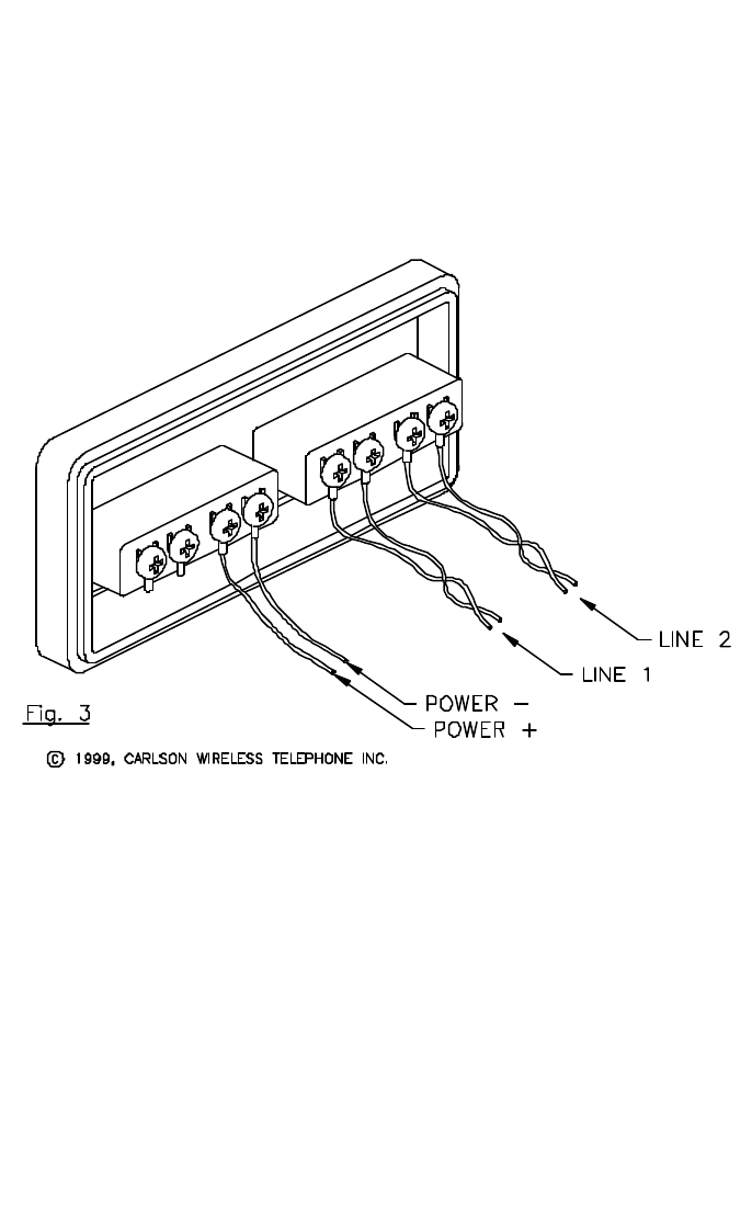
(2) Connecting the feed cable to the inside equipment.
Inside the building the feed cable is brought out to a terminal block consisting
of 4 pairs of screw down connections. The following diagram shows how to
wire the connectors.
Carlson Wireless USA revision 1.05 Page 10
(4) Rough alignment. This is usually easier then it would seem. Since it is a
prerequisite that you have line of sight between the two points, here are sev-
eral ideas that have worked for installers:
(1) If you can see the other unit, simply aim the tubes towards each other. (2)
During midday, use a large mirror to create a bright reflection approximately
towards the other site while someone watches for the flash.
(3) Plot out the path on a topo map and set the antennas using a compass.
How close in alignment do they need to be? +/- 10 degrees will be ade-
quate for most paths using the 13.5 dB gain antenna. Certain paths that have
a low fade margin may require a more accurate setting.
Final alignment. This is usually done by connecting a standard cordless
phone to the FXS or FXO end, and then give a best guess to the direction,
establish a connection and rotating the antennas both right and left noting the
points where the signal disappears, (assuming that it does) and then center-
ing them between those cutoff points.
Remember to leave the antenna elements vertical, or perpendicular to
the ground for best performance
Carlson Wireless USA revision 1.05 Page 11
TROUBLESHOOTING
The outcome of the installation is dependent on the weakest link.
Five things are paramount to his system working well:
(1) An acceptable radio path
(2) Other users of the 2.4 GHz ISM band.
(3) Customer’s wiring of power and telephone circuits
(4) Antenna alignment within +/- 10 degrees for i-WLL-15
(5) Quality of the telephone lines from the telephone company
(6) Quality of the power supplies.
If the system appears dead, with no tones audible on the subscriber phone,
look for a wiring fault. You can test for loop voltage at the FXS end by meas-
uring the voltage on line 1 and line 2. Each should be 30 VDC. Next would be
checking the DC current used by each unit. For example the sub unit with 16
Volts provided should draw (3W / 16V) ~200 mA. at idle and ~400 mA with
both lines off hook. This test is very useful to prove out the wiring.
Next, it will be important to confirm that a local test at the FXO base site was
done. If not, you will need to bring the FXS unit back to the base site and
temporarily connect the FXS unit up and confirm proper local operation.
If the system cuts in and out, or fails to draw dial tone, look for an alignment
problem or path obstruction. Also you should check to see that the antenna
elements are vertical to earth, and if not in a rural area you may have a con-
gested frequency band.
If you are having cross-talk between lines, examine the phone cabling making
sure it is individually twisted pairs, preferably with a Category 5 rating.
Software Updates: Inappropriate operations (bugs) reported by users will be
evaluated by the engineering department. Fixes will be available from our web
site with instructions
If after checking the above, you are still having problems please contact our
sales dept. for technical assistance by phone or email. A note about the
power supplies: The FXO unit will draw 2-3W off hook or idle. The sub will
draw 3W idle and 6W with both lines off hook. We suggest over-sizing the
supplies by 2 times. For example a 12 volt filtered DC wall transformer supply
@ 1.00 Amp (12W) or even better a 24 volt filtered DC @ 500 mA. (12W).
They are much more likely to survive power fluctuations and high tempera-

Carlson Wireless USA revision 1.05 Page 12
SPECIFICATIONS
BASEBAND PERFORMANCE
Voice Coding Uncompressed 64 kb/s PCM
Signaling DTMF is passed through
Modem Support up to V.34-1996, (33.6 kb/s)
Fax Support up to G4, unrestricted
Digital Interface Asynchronous, RS-232, DCE
Idle Channel Noise -68 dBm max (20 dBrnCo)
End-to-End System Latency 5 ms typical
NETWORK INTERFACE SPECIFICATIONS - FXO or Central Office
Line Impedance 900 Ohm +2.16 uF, loop start
Maximum Loop Length 1500 Ohms
Ring Equivalent Number 0.5B
Ring Detect 40-110 Vrms, 17-34 Hz
2 Wire Return Loss (ERL) Greater than 20 dB
NETWORK INTERFACE SPECIFICATIONS - FXS or Subscriber
Line Impedance 600 Ohm, loop start
Loop Current 27 mA fixed
Maximum Loop Length 600 Ohms
Ringing Voltage 86 Vrms Modified Square Wave
Ringing Frequency 20 Hz standard., 16, 25 Hz opt
Ringing Load 5 REN-B max (5 Watts)
2 Wire Return Loss (ERL) Greater than 20 dB
Carlson Wireless USA revision 1.05 Page 9
(3) Lightning protection. Grounding of the drain wire: For feed cable runs of
less than 35 feet (10m) and not located in a highly active lightning area, con-
necting the bare drain wire to a copper clad ground rod driven at least 6 feet
(2m) into moist earth with a short copper #8 AWG wire at the point of the ter-
minal block may suffice. The antenna mast must also be grounded in the
same fashion by a separate grounding rod. However if the run is longer than
35 feet or the location is in a highly active lightning area then a standard 3
way gas tube protector must be added. Connecting information on this device
is provided by it’s manufacturer.
(2) Connecting the feed cable to the inside equipment.
Inside the building the feed cable is brought out to a terminal block consisting
of 4 pairs of screw down connections. The following diagram shows how to
wire the connectors.

Carlson Wireless USA revision 1.05 Page 8
INSTALLATION
Note that the installation of the FXO and FSO units are similar
(1) Connecting the feed cable to the outside unit. On the mounting end of
the tube there is an end cap with a weather sealing clamp. This allows the
feed cable the penetrate the housing and remain sealed to outside weather.
Begin with the removal of the rear end cap by using a coin as a wedge and
working your way around the tube until the end cap pops off. Inside the end is
the electronics assembly consisting of the printed circuit boards and inte-
grated antenna. There are two screw down terminal blocks on the exposed
end. One block has 2 connections and it is where the DC power supply con-
nects. The other block has 4 connections, for telephone lines 1 and 2. The
following diagram shows how to wire the connectors. Make sure to hand
tighten only the weather sealing cord grip.
Note: Make sure that the antenna elements are vertical or perpen-
TIMESAVER TIP! By installing the FXO unit first, you can test the sys-
tem locally by temporarily connecting the FXS unit up at the FXO site and
proving your connections. This can greatly simplify any trouble shooting you
may have later.
Carlson Wireless USA revision 1.05 Page 13
POWER REQUIREMENTS & CONSUMPTION
Filtered DC 12 to 48 volts
Absolute Maximum / Minimum 10 to 55 volts
Sub End, On-Hook 3 Watts max
Sub End, 2 Lines Off-Hook 6 Watts max
Base End - On or Off-Hook 3 Watts max
RF PERFORMANCE
Frequency Range 2400 to 2483.5 MHz
RF Channels 7+1 (admin)
Spreading Method Direct Sequence
Modulation BPSK
PN Bit Length 16
Processing Gain 12.04 dB
ERP (Effective Radiated Power) +28.5 dBm
Receive Sensitivity -93 dBm @10-6 BER
System Range 10 miles (16.1 km)
PHYSICAL & ENVIRONMENTAL SPECIFICATIONS
Enclosure Material ABS weather sealed plastic
Dimensions ( inches) 4 1/2 diameter x 30 in length
Dimensions (cm) 11 diameter x 76 in length
Shipping Weight (system complete) 24 lbs (11 kg)
Operating Temp -30 to +65 degrees C
Humidity 10 to 95% non-condensing
Shock and Vibration Mil standard 810 D
Exposure to the Elements Nema 4X, all except submerged
WARRANTY 2 years parts and labor - see detail
CERTIFICATIONS AND REGULATORY
FCC Reg No., Part 68 BMD USA – 27773-PT-E
FCC Reg No., Part 15 OPA-I-WLL, Pending Final
Industry Canada CS-03 3448-10241A
Industry Canada RSS-210 Pending Final
Carlson Wireless USA revision 1.05 Page 14 Carlson Wireless USA revision 1.05 Page 7
(2) Other users of the 2.400 to 2.483 GHz ISM band.
The ISM or Industrial, Scientific, and Medical band, is shared with many other
type of services. Fortunately most of the users are located in urban areas,
leaving sharing concerns down to consumer microwave ovens and other
spread spectrum rural telephone users. The I-WLL-15 system has divided the
ISM band into 8 sub-bands or channels. One channel is used for system ad-
ministration with the system then randomly selecting 1 of the 7 remaining
channels for operation. The functionality of the i-WLL–15 system de-
pends on the existing and forecasted spectrum usage in the radio
path. Due to the characteristics of the spread spectrum radio, the ITU
(International Telecommunication Union) was able to coordinate this band
globally for unlicensed use. This means that any user has to accept all other
users in this band, interfering or not.
(3) Availability of telephone service and power.
The I-WLL-15 system consists of two units. One is designed to connect to
the standard phone lines provided by a local telephone company office (FXO
side) and the other connects to the telephone instruments such as; DTMF
(touch tone) telephones, fax machines, and computer modems (FXS side) via
individually twisted pair phone/data cable. The system is very flexible about
voltage requirements. 12 to 55 Volts DC with the current being inversely pro-
portional to the voltage, the power use being approximately 3 Watts for the
FXO side, in any state, and 3 to 6 Watts for the FXS side depending on us-
age state. We recommend over-sizing the supply by 1.5 to 2 times. Depend-
ing on the length, most installations can use 4 twisted pair, #22 AWG feed
cable. This will drop about 1 volt per 100 feet of length. To allow for most any
voltage drop situation we recommend 24 volt, 500 mA power supplies. Using
non-twisted IW or Quad phone wiring will result in cross-talk between
lines.
(4) Mounting structure.
Warning! Use extreme caution to avoid contact with any high voltage
power lines when constructing antenna structures!
The enclosure is designed to mount on a steel vertical pipe, commonly known
in North America as 1 to 2 inch pipe ( 2.5 to 5 cm ), with an actual outside
diameter of 1.3 to 2.5 inches ( 3 to 6 cm ). This mast must not move signifi-
cantly in any anticipated wind and must be connected with a short copper #8
AWG wire to a copper clad ground rod driven at least 6 feet (2m) into moist
earth.

Carlson Wireless USA revision 1.05 Page 6
SYSTEM PLANNING
Certain requirements are necessary for the i-WLL-15 system to function.
(1) A radio path with losses fitting within the capacity of the system.
We have a chart showing various antenna and distance combinations.
What’s an acceptable “Link Margin“? An accepted theory is that 10 dB of
fade margin will deliver a 90% reliability and 20 dB will deliver a 99% reliability
etc.. There are other factors that affect this including vertical or horizontal po-
larization. At 2.4 GHz there is only a small ground wave component involved
in the radio propagation. This means that the above numbers are presuming
clear LOS (line of sight). Multi-path occurs when a reflector such as earth’s
terrain or man made structures cause additional delayed signals to be re-
ceived. If a signal was delayed 180 degrees out of phase with the line of sight
signal, and the magnitudes are the same, they will cancel out completely! In
the real world, if you do have line of sight path, multi-path degradation is the
reason why you need a minimum of 6 to 10 dB of margin. If you don’t have
line of sight, multi-path could easily cause 20 dB of degradation.
Distance Distance Model Path Loss ERP Link Margin
in Miles in km in dB in dBm
1.5 2.4 I-WLL-15 108 27 27
2.0 3.2 I-WLL-15 110 27 25
5.0 8.0 I-WLL-15 118 27 17
7.0 11.3 I-WLL-15 121 27 14
8.0 12.9 I-WLL-15 122 27 13
8.0 12.9 I-WLL-25 122 29 17
10.0 16.1 I-WLL-15 124 27 11
10.0 16.1 I-WLL-25 124 29 15
12.0 19.3 I-WLL-25 126 29 13
15.0 24.1 I-WLL-25 128 29 11
20.0 32.2 I-WLL-35 130 36 24
25.0 40.2 I-WLL-35 132 36 22
50.0 80.5 I-WLL-35 138 36 16
Fade Margin Chart
Carlson Wireless USA revision 1.05 Page 15
PARTS LIST i-WLL-15
PART-REV # DESCRIPTION
19 – L PCB, LINE INTERFACE & POWER REGULATOR
18 – S PCB, DIGITAL TOP
17 – B MOUNT, FRONT ANTENNA
16 – (RESERVED)
15 – (RESERVED)
14 – G U-BOLT, 2-3/4 INCH
13 – E CLAMP BASE, 2 3/4 INCH
12 – B U-BOLT, 4-1/2 INCH
11 – C END CAP, FRONT
10 – (RESERVED)
09 – A RING, RETAINING
08 – G BRACKET, SADDLE
07 – G PLATE, MOUNTING
06 – B GRIP, CABLE & SEALING GLAND
05 – C O-RING 1/8 x 3.50 x 3.75
04 – B ANTENNA, 16 ELEMENT 13.5 dB GAIN
03 – D SHIELD, INNER SS
02 – D HOUSING, OUTER
01 – E END CAP, REAR

Carlson Wireless USA revision 1.05 Page 16
Consumer and US Regulatory Information
Connection to the telephone network
1. The Federal Communications Commission (FCC) has established rules
which permits this device to be directly connected to the telephone network.
2. If this device is malfunctioning, it may also be causing harm to the tele-
phone network; this device should be disconnected until the source of the
problem can be determined and until repair has been made. If this is not
done, the telephone company may temporarily disconnect service.
3. The telephone company may make changes in its technical operations
and procedures; if such changes affect the compatibility or use of this device,
the telephone company is required to give adequate notice of the changes.
4. If the telephone company requests information on what equipment is con-
nected to their lines, inform them of:
(a) The telephone number that the unit is connected to
(b) The ringer equivalence number
(c) The USOC jack required
(d) The FCC Registration number
Item (b) and (c) are indicated on the label.
5. In the event of equipment malfunction, all repairs should be performed by
our company or an authorized agent. It is the responsibility of users requiring
services to report the need for service to our company or to one of our author-
ized agents.
Service can be obtained at: Carlson Wireless Telephone Inc.,
1150 Evergreen Road
P.O. Box 2400,
Redway, CA 95560 USA,
Tel: +1 707 923 9593
FCC Reg No., Part 68 BMD USA – 27773-PT-E
Notification to the telephone company
The equipment complies with Part 68 of the FCC rules. You will find the label
located on the device. This label contains the FCC Registration Number and
the Ringer Equivalence Number ((REN) for this equipment. You must, upon
request, provide this information to your telephone company.
Carlson Wireless USA revision 1.05 Page 5
The i-WLL breakthrough offers many advantages not found in the market to-
day:
•Never needs tuning because i-WLL is a 100% digital, self-configuring,
eight channel system. This simplifies installation and greatly reduces the
need for maintenance and service over time.
•Complete privacy is assured by the fully encrypted, spread-spectrum
modulation scheme.
•Highly efficient spectrum use from a unique combination of FDMA and
CDMA.
•Seamless integration with the global telephone network assured by i-
WLL’s worldwide ISDN system architecture with full 144 kbps bandwidth.
•No individual license needed for operation - i-WLL uses the globally li-
cense-free 2.4 GHz ISM frequency band.
•Flexible voltage – low power usage - just 3 to 6 Watts at any DC voltage
between 12 and 55V.
•Small, lightweight, self-contained units make i-WLL easy to install - no
special expertise needed. i-WLL FXO (central office) and FXS
(subscriber) units - which include all electronics, antenna and RF ca-
bling - are housed in a weatherproof enclosure 4.5" in diameter by 30"
long (11.5 x 76.2 cm) .

Carlson Wireless USA revision 1.05 Page 4
UNPACKING
The i-WLL-15 system will arrive in one box approximately 32 x 16x 9 inches
(80 x 40 x 23 cm). Small amounts of feed cable and power supplies may also
be included in this box if ordered.
Caution!
1. There are 2 large U-bolts holding the outer housing to the mounting plate of
each system. The fasteners on these are self locking nuts. DO NOT TURN
OR ROTATE THESE NUTS. They are set to a specific torque and if over-
torqued the housing will distort potentially damaging the electronic modules
inside.
2. DO NOT REMOVE THE FRONT END CAP. The seal is not lubricated for
removal and reinstallation. All of the electronics and antenna assembly are
serviced though the rear (mount-side) end cap.
SCOPE OF MANUAL
This manual is designed to support the installation, operation and mainte-
nance of the i-WLL–15 All-Digital Remote Wireless Telephone Link. To avoid
harm to persons or damage to the product please ensure that you have read
through the unpacking and installation sections before proceeding.
PRODUCT OVERVIEW
The i-WLL All-Digital, Internet-Ready, Remote Phone Link is a dual line,
point-to-point, spread spectrum telephone system that delivers v.34 data
rates, providing email and the Internet to your remote PC - as well as high-
quality voice! And both lines are fully independent and will transmit either
voice or data.
Carlson Wireless USA revision 1.05 Page 17
Radio interference
Carlson Wireless USA Model: i-WLL-15
This device complies with Part 15 of the FCC Rules. Operation is subject to
the following two conditions: (1) This device may not cause harmful interfer-
ence, and (2) This device must accept any interference received, including
interference that may cause undesired operation. Changes of modification not
expressly approved by the party responsible for compliance could void the
user’s authority to operate the equipment.
Notification to the telephone company cont’d
The REN is useful to determine the quantity of devices you may connect to
your telephone line and still have all of those devices ring when you telephone
number is called. In most, but not all, areas, the sum of the REN’s of all de-
vices connected to one line should not exceed five (5.0).
To be certain of the number of devices you may connect to your telephone
line , as determined by the REN, you should call your local telephone com-
pany to determine the maximum REN for your calling area.
Jack Types Needed
Connection to the telephone network should be made by using standard
modular telephone jack types (USOC) RJ11C or RJ11W.
Incidence of Harm
If your telephone equipment cause harm to the telephone network, the tele-
phone company may disconnect your service temporarily. If possible, they
will notify you in advance. But if advance notice is not practical, you will be
notified as soon as possible. You will be informed of your right to file a com-
pliant with the FCC.
Rights of the Telephone Company
Your telephone company may make change in it’s facilities, equipment, op-
erations or procedures that could affect the proper functioning of your equip-
ment. If they do, you will be notified in advance to give you an opportunity to
maintain uninterrupted telephone service.
Coin Service or Party Use Line
This equipment may not be used on the coin service provided by the tele-
phone company. Connection to party lines is subject to state tariffs.

Carlson Wireless USA revision 1.05 Page 18
Carlson Wireless USA Limited Warranty
Carlson Wireless Telephone (CWT) or Carlson Wireless USA, Collectively
referred to as "Carlson“) will repair this product with new or rebuilt parts,
free of charge, in the USA or Puerto Rico for two (2) years from the date of
original purchase in the event of a defect in material or workmanship. Mail-
in service in the USA can be obtained during the warranty period from a
Carlson Factory Service center by calling +1-707-923 9593, for a RMA
(Return Materials Authorization) number and mail your product adequately
packed, postage paid and insured to the address provided. This warranty is
extended only to the original purchaser. A purchase receipt or other proof of
date of original purchase will be required before warranty performance is
rendered. This warranty only covers failures due to defects in materials or
workmanship which occur during normal use. It does not cover damage
which occurs in shipment or failures which are caused by products not sup-
plied by Carlson or failures which result from accident, misuse, abuse, ne-
glect, mishandling, misapplication, alteration. modification, lightning, line
power surge, introduction of sand, dust, humidity and liquids or commercial
use of the product, or service by anyone other than a Carlson Factory Serv-
ice center or authorized Carlson Service center, or damage that is attribut-
able to acts of God.
Limits and Exclusions
There are no express warranties except as listed above.
CARLSON SHALL NOT BE LIABLE FOR INCIDENTAL OR CONSEQUEN-
TIAL DAMAGES RESULTING FROM THE USE OF THIS PRODUCT, OR
ARISING OUT OF ANY BREACH OF THIS WARRANTY. ALL EXPRESS
AND IMPLIED WARRANTIES, INCLUDING THE WARRANTIES OF MER-
CHANTABILITY AND FITNESS FOR A PARTICULAR PURPOSE, ARE
LIMITED TO THE APPLICABLE WARRANTY PERIOD SET FORTH
ABOVE.
Some states do not allow the exclusion or limitation of incidental or conse-
quential damages, or limitations on how long an implied warranty lasts, so
the above exclusions or limitations may not apply to you. This warranty
gives you specific legal rights and you may also have other rights which
vary from state to state. If a problem with this product develops during or
after the warranty period you may contact your dealer or Service center. If
the problem is not handled to your satisfaction, fax, phone, or write the
company at the address indicated in the service section of this manual.
Carlson Wireless USA revision 1.05 Page 3
TABLE OF CONTENTS
SCOPE OF MANUAL 4
UNPACKING 4
PRODUCT OVERVIEW 4
SYSTEM PLANNING 6
INSTALLATION 8
TROUBLESHOOTING 11
SPECIFICATIONS 12
PARTS LIST 14
CUSTOMER INFORMATION 16
WARRANTY 18

Carlson Wireless USA revision 1.05 Page 2
i-WLL, the i-WLL logo , Carlson Wireless USA, and the Carlson Wire-
less logo are registered trademarks of Carlson Wireless Telephone Inc.
Any trademarks, trade names, service marks, or service names owned
or registered by any other company and used in this manual are the
property of their respective companies. Copyright 1999, Carlson Wire-
less Telephone Inc. All rights reserved.
The employees and shareholders of Carlson Wireless Telephone Inc.
wish to thank you for your purchase of the i-WLL product. For more in-
formation about the company, see our web site at http://www.wireless-
telephone.com
Carlson Wireless USA revision 1.05 Page 19
(This page is intentionally left blank.)

Carlson Wireless USA revision 1.05 Page 20
CARLSON WIRELESS TELEPHONE, Inc.
CARLSON WIRELESS USA
USA Headquarters:
1150 Evergreen Road
P.O. Box 2400
Redway, CA 95560 USA
Tel: +1 707 923 9593
Fax: +1 707 923 1913
Email sales@wireless-telephone.com
DISTRIBUTED BY:
Publication date – Oct 99
About Carlson Wireless Telephone Inc.
Carlson Wireless Telephone, Inc. was formed in March 1999 as
a privately held corporation based in Redway, California. Carlson
Wireless Telephone (CWT) is dedicated to designing, manufac-
turing and marketing state-of-the-art digital WLL (wireless local
loop) telephone systems that provide high-quality voice and data
for rural and remote telephone users worldwide.
CWT was founded by James Carlson following a 15-month prod-
uct development by a team of engineers at Carlson Engineering
Services (CES), a private engineering design firm. In 1999 CWT
purchased the rights to the digital wireless telephone system de-
signed by CES. CWT will market and manufacture the product,
which has been named "The i-WLL Internet-Ready, All-Digital
Wireless Remote Telephone Link."
CWT is marketing the i-WLL product through established tele-
com and wireless equipment distributors. Please contact our
sales department +1 707 923 9593, or sales@wireless-
telephone.com for more information.
Carlson Wireless USA revision 1.05 Page 1
INSTALLATION & OPERATING MANUAL
MODEL NO. i-WLL-15
Caution! - Please read the sections on Un-
packing, Planning, and Installation before
installing this equipment