Carrier Fire and Security Americas 10103358G1 WTI Smart User Manual
UTC Fire & Security Americas Corporation, Inc WTI Smart
User Manual
Introduction
These instructions are applicable to the Wireless
TRACcess Interface (WTI) installation and the Surface
Mount installation. Read these instructions before
replacing the bezel interface with the wireless interface. If
the interface is not mounted accurately, it will not function
properly. Supra will not be responsible for replacing the
interface if it is damaged or destroyed upon removal.
Hardware Provided
• Surface Mount Drill template (P/N 10103323P1)
• WTI Drill template (P/N 43336)
• Exterior WTI interface plate
• Two(2)setsoffour(4)#8atheadscrews(two
different screw lengths for the mounting plate)
• Four (4) #8 × 5/16 in. pan-head screws and lock
washers (for electronics enclosure)
• Six(6)#4×1/2in.atheadscrews(forelectronic
enclosure lid)
• Plastic weather cover assembly
CAUTION: The electronics in this package are
electrostatic sensitive devices. Before installing the
unit, discharge or use a grounding belt.
Hardware Not Provided
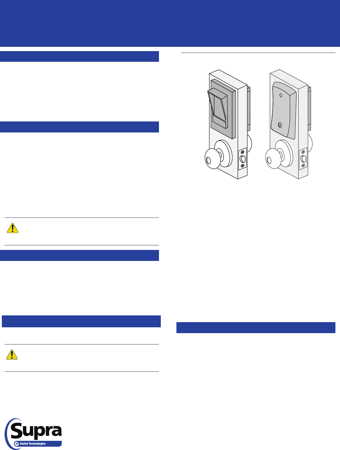
Figure 1. Bezel Interface and Wireless Interface
Installation Notes
Accurate mounting is essential for proper functioning of
the WTI.
CAUTION: Battery failure may result with water
inltration. Follow to recommended precautions
below to reduce water exposure.
For Surface Installation only
Sealant Selection:
• Choose sealants appropriate for sealing surfaces
• Waterproof
• Exterior rated
• UV resistant
Mounting Surface Condition and Preparation:
• Suitable for sealing
• Free of loose material
• Clean and dry
• Flat and free of irregularities
Sealant Application:
• Use and apply sealants per the Manufacturers
instructions
• Before mounting, apply RTV sealant on four (4) plate
screws on the back surface of the plate
• Apply sealant around mounting holes (in corners)
and around the cable hole
• Apply sealant around mounting plate perimeter
Remove
To replace the bezel interface with the wireless interface:
1. Remove the screws from the electronics enclosure lid.
2. Remove the lid.
Note: Make careful notes of the connection pin-
outs as the exterior WTI interface retrot plate will be
reconnected similarly.
3. Disconnect the wiring plugged into the electronics
enclosure.
4. Remove the four (4) screws that secure the electronics
enclosure to the interior plate.
5. Remove the electronics enclosure.
6. Remove the four (4) screws securing the old bezel
interface plate to the interior plate.
7. Remove the old interface plate.
Wireless TRACcess®Interface(WTI)Retrot
Installation Instructions
• Level or punch
• Pen or pencil
• RTV sealant
• Fasteners (for
mounting plates)
• Drill
• Drill bits
• File
• Phillips screwdriver
• Conduit or conduit
connectors
• Wire or wire connectors

WTI Installation
1. Feed the 4-wire plug from the exterior WTI interface
plate through the cabling hole in the door, and secure
the interior mounting plate to the exterior WTI interface
plate.
CAUTION: Do not overtighten the long screw. If the
screw does not fully secure the plates to the door
when tightened, use a shorter screw.
2. Insert and tighten screws through the interior mounting
plate. For 1-1/4 to 1-1/2 in. (32 to 38 mm) doors, use 3/4
in. (19 mm) screws. For 1-1/2 to 2 in. (32 to 51 mm), use
1-1/4 in. (38 mm) screws.
Note: Attach the wires after securing the enclosure.
3. Feed the 4-wire plug from the exterior WTI interface
plate, and the 2-wire cable from the lockset through the
cabling hole in the electronics enclosure.
4. Using (4) #8 × 5/16 in. (16 mm) pan-head screws and
lock washers, insert and tighten the screws and lock
washers securely to attach the electronics enclosure to
the interior mounting plate.
5. Connect the 2-wire cable and the 4-wire plug as they
were previously connected in the electronics enclosure.
Note: In the case of 9V cells, make sure the wires point
toward you as you secure them in place and the battery
connectors should point toward the circuit board.
6. Inspectandconrmthatthebatteriesintheelectronics
enclosure are properly inserted and connected to the
battery terminal connections and secured in the battery
holder compartment.
Surface Mount Installation
1. Feed the 4-wire plug from the surface mount plate
through the wall and secure the surface mount interface
plate (fasteners not included).
2. Locate and mount the interior mounting plate (fasteners
not included).
Note: Attach the wires after securing the enclosure.
3. Feed the 4-wire plug from the surface mount plate,
through the cabling hole in the electronics enclosure.
4. Using (4) #8 × 5/16 in. (16 mm) pan-head screws and
lock washers, insert and tighten the screws and lock
washers securely to attach the electronics enclosure to
the interior mounting plate.
5. Connect the 2-wire cable and the 4-wire plug as they
were previously connected in the electronics enclosure.
Note: In the case of 9V cells, make sure the wires point
toward you as you secure them in place and the battery
connectors should point toward the circuit board.
6. Inspectandconrmthatthebatteriesintheelectronics
enclosure are properly inserted and connected to the
battery terminal connections and secured in the battery
holder compartment.
Test and Complete Installation
1. Perform an Install function with a valid TRACcess eKEY.
Note: Refer to the TRACcess eKEY user instructions for
step by step operation. Test the lock rst with the door open
and then with the door shut to ensure the lock strike catches
the door frame.
2. Test the lock operation using the TRACcess eKEY.
Note: If the device is a TRAC-Lock BT Smart programmed
for TIMED mode, the light will remain ashing for a
preprogrammed period of time, during which the door may be
opened. If the device is a TRAC-Lock BT Smart programmed
for LATCHED mode, once the light ashes green, the door
may be opened until the lock is reset. If it is programmed for
LATCHED mode, be sure to reset the lock.
3. When you test the lock with your key, the LED at the top
oftheinterfacewillashgreen,indicatingthedoormay
be opened.
4. After the lock is tested successfully, place the lid on the
back of the electronics enclosure and position the logo
directly over the battery pack.
5. Inserttheprovidedsix(6)#4×1/2in.(13mm)athead
screws into the predrilled holes.
Note: Do not overtighten the screws, it may damage the
electronics enclosure and prevent the lid from being securely
fastened.
6. Hand-tighten the upper right corner screw and hand-
tighten the remaining screws in a clockwise order.
7. Record the device serial number and location.
Battery removal/disposal
Replacing the interface is a good time to service the
batteries. The batteries should be periodically replaced. This
product contains either three (3) 9-volt batteries or eight (8)
AA batteries. To remove the batteries, do the following:
1. Remove the lid from the electronics enclosure.
2. Pull the batteries out of the slots.
For proper recycling, dispose of all batteries as required by
local ordinances or regulations.
Regulatory Compliance
United States (FCC)
This device complies with part 15 of the FCC rules. Operation is subject to
the following conditions:
1. This device may not cause harmful interference.
2. This device must accept any interference received, including
interference that may cause undesired operation
Changesormodicationsnotexpresslyapprovedbythepartyresponsible
for compliance could void the user’s authority to operate the equipment.
Canada (IC)
This Class B digital apparatus complies with Canadian ICES-003. Cet
appareil numérique de la classe B est conforme à la norme NMB-003 du
Canada.
This device complies with Industry Canada license-exempt RSS standard(s).
Operation is subject to the following two conditions: (1) this device may
not cause interference, and (2) this device must accept any interference,
including interference that may cause undesired operation of the device.
Cet équipement est conforme à la (aux) norme(s) canadienne(s) d’exemption
de licence RSS Industry Canada. Son opération est sujette aux deux
conditions suivantes: (1) cet équipement ne provoquera aucune interférence
et (2) cet équipement doit tolérer toute interférence pouvant provoquer une
opération indésirable de l’équipement.
European Union (CE)
This Class B digital apparatus conforms to the requirements of the following
EU directives:
1. R&TTTE Directive (1999/5/EC)
2. WEEE Directive (2002/96/EC)
Australia / New Zealand
This apparatus fully complies with ACMA requirements and is C-Tick marked.
P/N 10103022P1-01 Rev C
© 2014 United Technologies Corporation. All rights reserved.