Carrier 38QRR018300 User Manual HEAT PUMP Manuals And Guides 1008629L
User Manual: Carrier 38QRR018300 38QRR018300 CARRIER HEAT PUMP - Manuals and Guides View the owners manual for your CARRIER HEAT PUMP #38QRR018300. Home:Heating & Cooling Parts:Carrier Parts:Carrier HEAT PUMP Manual
Open the PDF directly: View PDF ![]() .
.
Page Count: 10
Installation Instructions
to the expe_
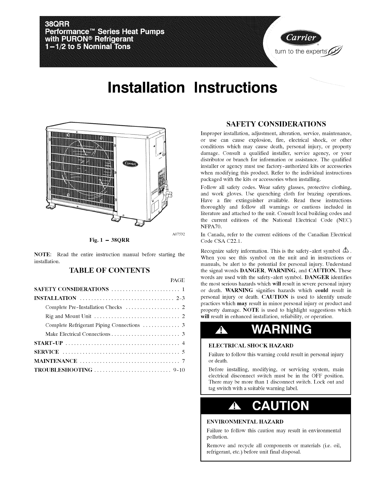
A07532
Fig. 1 -38QRR
NOTE: Read the entire instruction manual before starting the
installation.
TABLE OF CONTENTS
PAGE
SAFETY CONSIDERATIONS ........................ 1
INSTALLATION ................................. 2-3
Complete Pre-Installation Checks ................... 2
Rig and Mount Unit .............................. 2
Complete Refrigerant Piping Connections ............. 3
Make Electrical Connections ........................ 3
START-UP ........................................ 4
SERVICE ......................................... 5
MAINTENANCE ................................... 7
TROUBLESHOOTING ........................... 9-10
SAFETY CONSIDERATIONS
Improper installation, adjustment, alteration, service, maintenance,
or use can cause explosion, fire, electrical shock, or other
conditions which may cause death, personal injury, or property
damage. Consult a qualified installer, service agency, or your
distributor or branch for information or assistance. The qualified
installer or agency must use factory-authorized kits or accessories
when modifying this product. Refer to the individual instructions
packaged with the kits or accessories when installing.
Follow all safety codes. Wear safety glasses, protective clothing,
and work gloves. Use quenching cloth for brazing operations.
Have a fire extinguisher available. Read these instructions
thoroughly and follow all warnings or cautions included in
literature and attached to the unit. Consult local building codes and
the current editions of the National Electrical Code (NEC)
NFPA70.
In Canada, refer to the current editions of the Canadian Electrical
Code CSA C22.1.
Recognize safety information. This is the safety-alert symbol /_.
When you see this symbol on the unit and in instructions or
manuals, be alert to the potential for personal iniury. Understand
the signal words DANGER, WARNING, and CAUTION. These
words are used with the safety-alert symbol. DANGER identifies
the most serious hazards which will result in severe personal iniury
or death. WARNING signifies hazards which could result in
personal iniury or death. CAUTION is used to identify unsafe
practices which may result in minor personal iniury or product and
property damage. NOTE is used to highlight suggestions which
will result in enhanced installation, reliability, or operation.
ELECTRICAL SHOCK HAZARD
Failure to follow this warning could result in personal iniury
or death.
Before installing, modifying, or servicing system, main
electrical disconnect switch must be in the OFF position.
There may be more than 1 disconnect switch. Lock out and
tag switch with a suitable warning label.
ENVIRONMENTAL HAZARD
Failure to follow this caution may result in environmental
pollution.
Remove and recycle all components or materials (i.e. oil,
refrigerant, etc.) before unit final disposal.
INSTALLATION
UNIT OPERATION AND SAFETY HAZARD
Failure to follow this warning could result in personal iniury
or equipment damage.
Puron (R-410A) refrigerant systems operate at higher
pressures than standard R-22 systems. Do not use R-22
service equipment or components on Puron refrigerant
equipment.
PERSONAL INJURY AND EQUIPMENT DAMAGE
HAZARD
Failure to follow this caution may result in personal iniury
and /or equipment damage.
DO NOT operate the unit without a filter or with grille
removed.
COMPLETE PRE-INSTALLATION CHECKS
Unpack Unit
Move the unit to final location. Remove unit from carton, being
careful not to damage service valves and grilles.
Inspect Shipment
File a claim with the shipping company if shipment is damaged or
incomplete. Check the unit nameplates to ensure units match job
requirements.
Consider System Requirements
Consult local building codes and NEC for special installation
requirements.
Allow sufficient space for airflow clearance, wiring, refrigerant
piping, and servicing unit. Locate unit so that condenser airflow is
unrestricted on both sides.
Unit may be mounted on a level pad directly on base legs or
mounted on raised pads at support points.
Matching the Heat Pump to an Indoor Unit
The 38QRR heat pump units can be matched to corresponding
indoor units. The 38QRR unit can be matched with under-ceiling
and residential fan coils and evaporator coils. Refer to separate
indoor unit literature for more information.
Expansion Device -Ducted System Cooling Mode
A hard shutoff, thermostatic expansion valve (TXV) is required at
the indoor section of the system for proper operation of these
products. If the indoor section of the system is not equipped with a
hard shutoff TXV, refer to Spec Sheet for the correct TXV kit to be
installed. Follow the instructions in the kit for proper installation.
Expansion Device -Duct Free System Cooling Mode
A piston is used as the metering device when installing a
40QAQ018-048 under-ceiling indoor unit. Refer to the indoor
unit instructions for details.
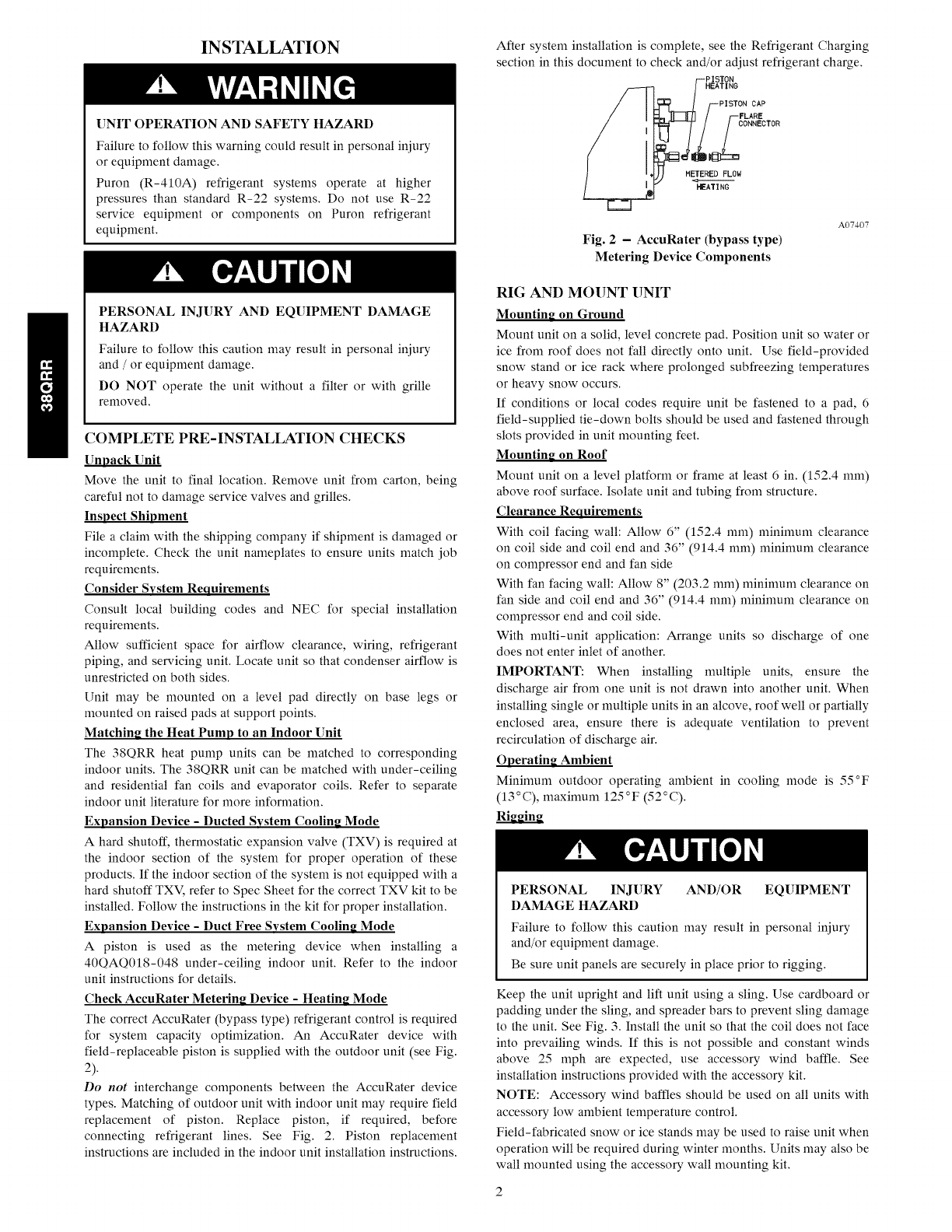
Check AccuRater Metering Device - Heating Mode
The correct AccuRater (bypass type) refrigerant control is required
for system capacity optimization. An AccuRater device with
field-replaceable piston is supplied with the outdoor unit (see Fig.
2).
Do not interchange components between the AccuRater device
types. Matching of outdoor unit with indoor unit may require field
replacement of piston. Replace piston, if required, before
connecting refrigerant lines. See Fig. 2. Piston replacement
instructions are included in the indoor unit installation instructions.
After system installation is complete, see the Refrigerant Charging
section in this document to check and/or acliust refrigerant charge.
HEATING
CAP
FLARE
ONNECTOR
HETERED FLOW
HEATING
Fig. 2 -AccuRater (bypass type)
Metering Device Components
A07407
RIG AND MOUNT UNIT
Mounting on Ground
Mount unit on a solid, level concrete pad. Position unit so water or
ice from roof does not fall directly onto unit. Use field-provided
snow stand or ice rack where prolonged subfreezing temperatures
or heavy snow occurs.
If conditions or local codes require unit be fastened to a pad, 6
field-supplied tie-down bolts should be used and fastened through
slots provided in unit mounting feet.
Mounting on Roof
Mount unit on a level platform or frame at least 6 in. (152.4 ram)
above roof surface. Isolate unit and tubing from structure.
Clearance Requirements
With coil facing walk Allow 6" (152.4 ram) minimum clearance
on coil side and coil end and 36" (914.4 ram) minimum clearance
on compressor end and fan side
With fan facing wall: Allow 8" (203.2 ram) n_ininmm clearance on
fan side and coil end and 36" (914.4 ram) n_ininmm clearance on
compressor end and coil side.
With multi-unit application: Arrange units so discharge of one
does not enter inlet of another.
IMPORTANT: When installing nmltiple units, ensure the
discharge air from one unit is not drawn into another unit. When
installing single or nmltiple units in an alcove, roof well or partially
enclosed area, ensure there is adequate ventilation to prevent
recirculation of discharge air.
Operating Ambient
Minimum outdoor operating ambient in cooling mode is 55°F
(13°C), naaxinmm 125°F (52°C).
PERSONAL INJURY AND/OR EQUIPMENT
DAMAGE HAZARD
Failure to follow this caution may result in personal injury
and/or equipment damage.
Be sure unit panels are securely in place prior to rigging.
Keep the unit upright and lift unit using a sling. Use cardboard or
padding under the sling, and spreader bars to prevent sling damage
to the unit. See Fig. 3. Install the unit so that the coil does not face
into prevailing winds. If this is not possible and constant winds
above 25 mph are expected, use accessory wind baffle. See
installation instructions provided with the accessory kit.
NOTE: Accessory wind baffles should be used on all units with
accessory low ambient temperature control.
Field-fabricated snow or ice stands may be used to raise unit when
operation will be required during winter months. Units may also be
wall mounted using the accessory wall mounting kit.
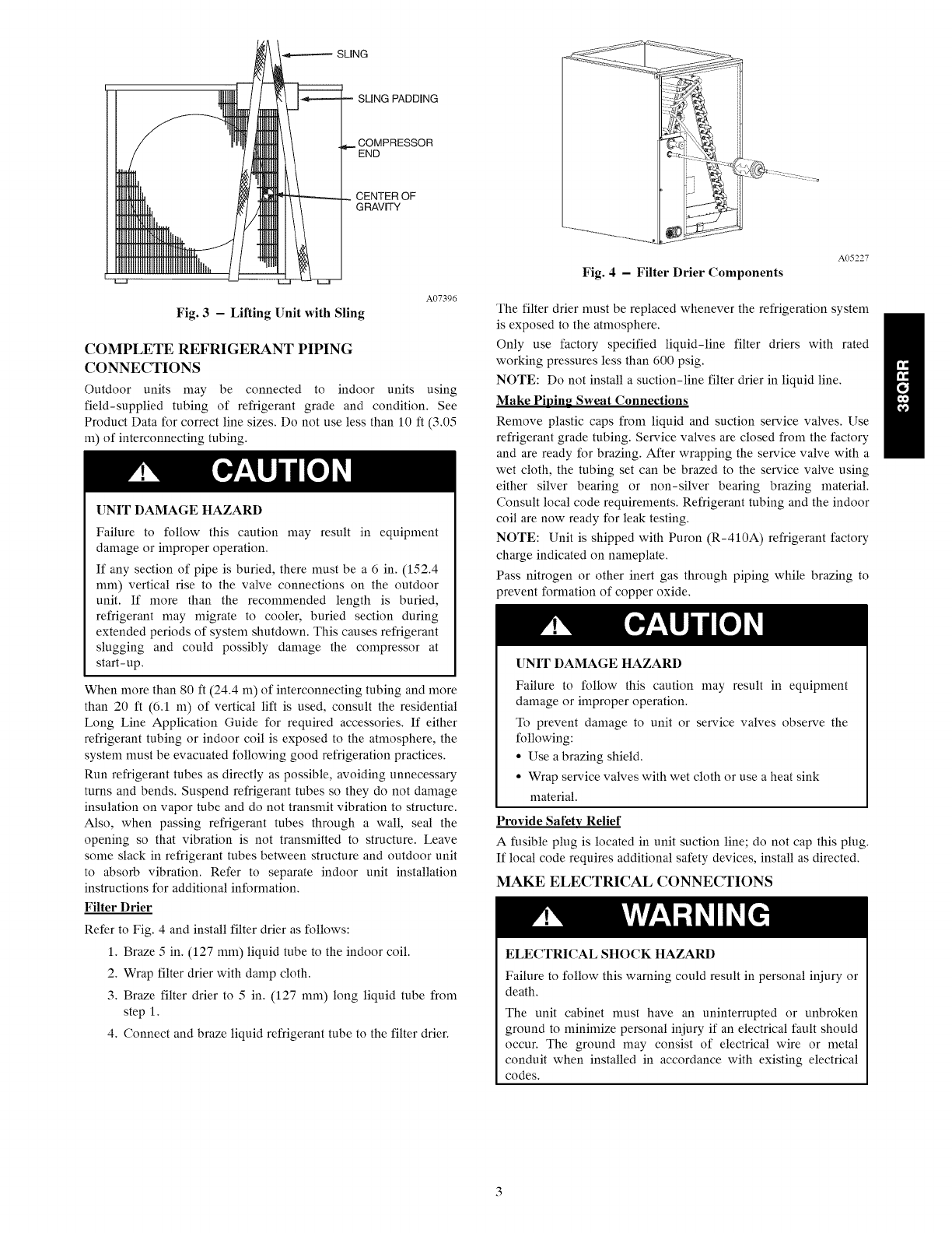
SLING
PADDING
COMPRESSOR
END
CENTER OF
GRAVITY
Fig. 3 - Lifting Unit with Sling
A07396
COMPLETE REFRIGERANT PIPING
CONNECTIONS
Outdoor units may be connected to indoor units using
field-supplied tubing of refrigerant grade and condition. See
Product Data for correct line sizes. Do not use less than 10 ft (3.05
m) of interconnecting tubing.
UNIT DAMAGE HAZARD
Failure to follow this caution may result in equipment
damage or improper operation.
If any section of pipe is buried, there nmst be a 6 in. (152.4
ram) vertical rise to the valve connections on the outdoor
unit. If more than the recommended length is buried,
refrigerant may nfigrate to cooler, buried section during
extended periods of system shutdown. This causes refrigerant
slugging and could possibly damage the compressor at
start-up.
When more than 80 fl (24.4 m) of interconnecting tubing and more
than 20 ft (6.1 m) of vertical lift is used, consult the residential
Long Line Application Guide for required accessories. If either
refrigerant tubing or indoor coil is exposed to the atmosphere, the
system nmst be evacuated following good refrigeration practices.
Run refrigerant tubes as directly as possible, avoiding unnecessary
turns and bends. Suspend refrigerant tubes so they do not damage
insulation on vapor tube and do not transnfit vibration to structure.
Also, when passing refrigerant tubes through a wall, seal the
opening so that vibration is not transnfitted to structure. Leave
some slack in refrigerant tubes between structure and outdoor unit
to absorb vibration. Refer to separate indoor unit installation
instructions for additional information.
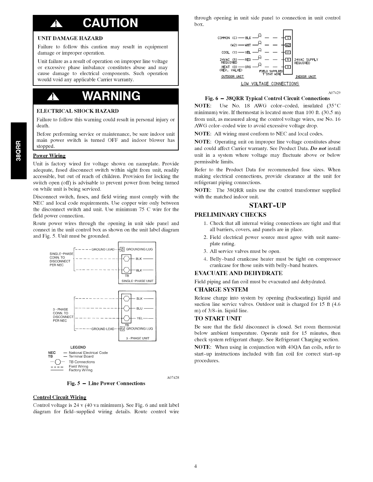
Filter Drier
Refer to Fig. 4 and install filter drier as follows:
1. Braze 5 in. (127 ram) liquid tube to the indoor coil.
2. Wrap filter drier with damp cloth.
3. Braze filter drier to 5 in. (127 ram) long liquid tube from
step 1.
4. Connect and braze liquid refrigerant tube to the filter drier.
Fig. 4 -Filter Drier Components
A05227
The filter drier nmst be replaced whenever the refrigeration system
is exposed to the atmosphere.
Only use factory specified liquid-line filter driers with rated
working pressures less than 600 psig.
NOTE: Do not install a suction-line filter drier in liquid line.
Make Piping Sweat Connections
Remove plastic caps from liquid and suction service valves. Use
refrigerant grade tubing. Service valves are closed from the factory
and are ready for brazing. After wrapping the service valve with a
wet cloth, the tubing set can be brazed to the service valve using
either silver bearing or non-silver bearing brazing material.
Consult local code requirements. Refrigerant tubing and the indoor
coil are now ready for leak testing.
NOTE: Unit is shipped with Puron (R-410A) refrigerant factory
charge indicated on nameplate.
Pass nitrogen or other inert gas through piping while brazing to
)revent formation of copper oxide.
UNIT DAMAGE HAZARD
Failure to follow this caution may result in equipment
damage or improper operation.
To prevent damage to unit or service valves observe the
following:
• Use a brazing shield.
• Wrap service valves with wet cloth or use a heat sink
material.
Provide Safety Relief
A fusible plug is located in unit suction line; do not cap this plug.
If local code requires additional safety devices, install as directed.
MAKE ELECTRICAL CONNECTIONS
ELECTRICAL SHOCK HAZARD
Failure to follow this warning could result in personal iniury or
death.
The unit cabinet must have an uninterrupted or unbroken
ground to nfininfize personal iniury if an electrical fault should
occur. The ground may consist of electrical wire or metal
conduit when installed in accordance with existing electrical
codes.
UNITDAMAGEHAZARD
Failureto follow this caution may result in equipment
damage or improper operation.
Unit failure as a result of operation on improper line voltage
or excessive phase imbalance constitutes abuse and may
cause damage to electrical components. Such operation
would void any applicable Carrier warranty.
ELECTRICALSHOCK HAZARD
Failure to follow this warning could result in personal iniury or
death.
Before performing service or maintenance, be sure indoor unit
main power switch is turned OFF and indoor blower has
stopped.
Power Wiring
Unit is factory wired for voltage shown on nameplate. Provide
adequate, fused disconnect switch within sight from unit, readily
accessible, but out of reach of children. Provision for locking the
switch open (off) is advisable to prevent power from being turned
on while unit is being serviced.
Disconnect switch, fuses, and field wiring must comply with the
NEC and local code requirements. Use copper wire only between
the disconnect switch and unit. Use minimum 75 C wire for the
field power connection.
Route power wires through the opening in unit side panel and
connect in the unit control box as shown on the unit label diagram
and Fig. 5. Unit must be grounded.
- .... GROUND LEAD -GROUNDING LUG
SINGLE-PHASE[_
_NcNi_NTOEc T BLK --
PER NEC / BLK--
I SIngLE'-PHASE UN,f
3-PHASE
CONN, TO
DISCONNECT
PER NEC
..... GROUND LEAD -_
LEGEND
NEC -- National Electrical Code
TB -- Terminal Board
O TB Connections
.... Field Wiring
Factory Wiring
BLK --
TB
_] GROUNDING LUG
3-PHASE UNIT
Fig. 5 - Line Power Connections
A07428
Control Circuit Wiring
Control voltage is 24 v (40 va minimum). See Fig. 6 and unit label
diagram for field-supplied wiring details. Route control wire
through opening in unit side panel to connection in unit control
box.
COHHON (C)--BLK --_ -- --
(M2)--WHT,.._ -- --
COOL (Y)--YEL "_
24VAC (R)--RED -_ -- --
REQUIRED
HEAT (O)--ORG -'_ -- --
(REV, VALVE) FIELD SUPPLIE
T'STAT WIRE
OUTDOOR UNIT
m
{Zg
24VAC SUPPLY
REQUIRED
INDOOR UNIT
LOW VOLTAGE CONNECT[0N5
A07429
Fig. 6 -38QRR Typical Control Circuit Connections
NOTE: Use No. 18 AWG color-coded, insulated (35°C
minimum) wire. If thermostat is located more than 100 ft. (30.5 m)
from unit, as measured along the control voltage wires, use No. 16
AWG color-coded wire to avoid excessive voltage drop.
NOTE: All wiring must conform to NEC and local codes.
NOTE: Operating unit on improper line voltage constitutes abuse
and could affect Carrier warranty. See Product Data. Do not install
unit in a system where voltage may fluctuate above or below
permissible limits.
Refer to the Product Data for recommended fuse sizes. When
making electrical connections, provide clearance at the unit for
refrigerant piping connections.
NOTE: The 38QRR units use the control transformer supplied
with the matched indoor unit.
START-UP
PRELIMINARY CHECKS
1. Check that all internal wiring connections are tight and that
all barriers, covers, and panels are in place.
2. Field electrical power source must agree with unit name-
plate rating.
3. All service valves must be open.
4. Belly-band crankcase heater must be tight on compressor
crankcase for those units with belly-band heaters.
EVACUATE AND DEHYDRATE
Field piping and fan coil must be evacuated and dehydrated.
CHARGE SYSTEM
Release charge into system by opening (backseating) liquid and
suction line service valves. Outdoor unit is charged for 15 ft (4.6
m) of 3/8-in. liquid line.
TO START UNIT
Be sure that the field disconnect is closed. Set room thermostat
below ambient temperature. Operate unit for 15 minutes, then
check system refrigerant charge. See Refrigerant Charging section.
NOTE: When using in coniunction with 40QA fan coils, refer to
start-up instructions included with fan coil for correct start-up
procedures.
SERVICE
ELECTRICALSHOCK HAZARD
Failure to follow this warning could result in personal injury
or death.
Before installing, modifying, or servicing system, main
electrical disconnect switch nmst be in the OFF position.
There may be more than 1 disconnect switch. Lock out and
tag switch with a suitable warning label.
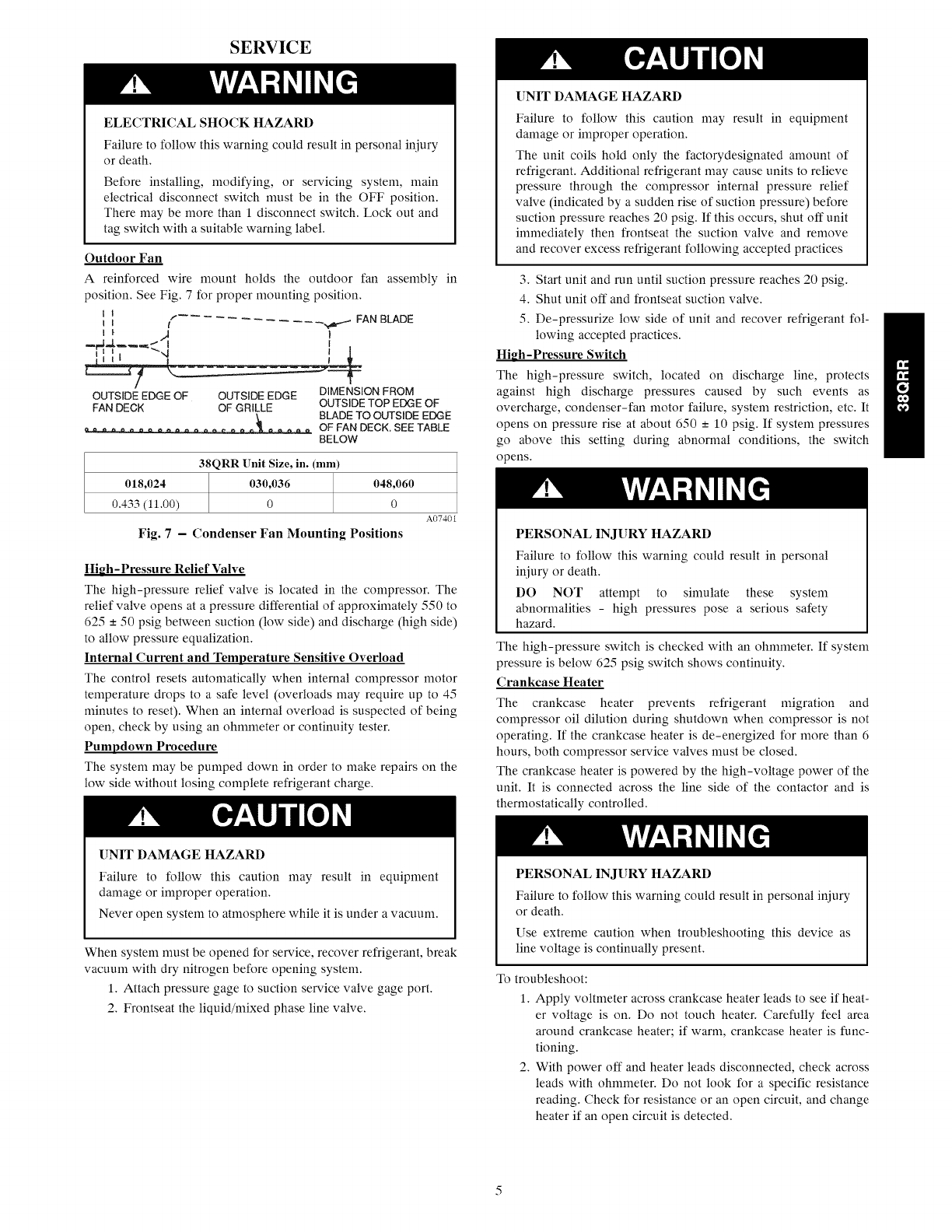
Outdoor Fan
A reinforced wire mount holds the outdoor fan assembly in
position. See Fig. 7 for proper mounting position.
II
i i " _,,,,_ FAN BLADE
I
OUTSIDEEDGE OF OUTSIDEEDGE DIMENSION FROM
FANDECK OF GRILLE OUTSIDETOP EDGEOF
BLADETO OUTSIDEEDGE
OF FANDECK.SEETABLE
BELOW
38QRR Unit Size, in. (mm)
018,024 030,036 048,060
0.433 (11.00) 0 0
Fig. 7 - Condenser Fan Mounting Positions
A07401
High-Pressure Relief Valve
The high-pressure relief valve is located in the compressor. The
relief valve opens at a pressure differential of approximately 550 to
625 - 50 psig between suction (low side) and discharge (high side)
to allow pressure equalization.
Internal Current and Temperature Sensitive Overload
The control resets automatically when internal compressor motor
temperature drops to a safe level (overloads may require up to 45
nfinutes to reset). When an internal overload is suspected of being
open, check by using an ohmmeter or continuity tester.
Pumpdown Procedure
The system may be pumped down in order to make repairs on the
low side without losing complete refrigerant charge.
UNIT DAMAGE HAZARD
Failure to follow this caution may result in equipment
damage or improper operation.
The unit coils hold only the factorydesignated amount of
refrigerant. Additional refrigerant may cause units to relieve
pressure through the compressor internal pressure relief
valve (indicated by a sudden rise of suction pressure) before
suction pressure reaches 20 psig. If this occurs, shut off unit
immediately then frontseat the suction valve and remove
and recover excess refrigerant following accepted practices
3. Start unit and run until suction pressure reaches 20 psig.
4. Shut unit off and frontseat suction valve.
5. De-pressurize low side of unit and recover refrigerant fol-
lowing accepted practices.
High-Pressure Switch
The high-pressure switch, located on discharge line, protects
against high discharge pressures caused by such events as
overcharge, condenser-fan motor failure, system restriction, etc. It
opens on pressure rise at about 650 -+ 10 psig. If system pressures
go above this setting during abnormal conditions, the switch
opens.
PERSONAL INJURY HAZARD
Failure to follow this warning could result in personal
injury or death.
DO NOT attempt to simulate these system
abnormalities - high pressures pose a serious safety
hazard.
The high-pressure switch is checked with an ohmmeter. If system
pressure is below 625 psig switch shows continuity.
Crankcase Heater
The crankcase heater prevents refrigerant migration and
compressor oil dilution during shutdown when compressor is not
operating. If the crankcase heater is de-energized for more than 6
hours, both compressor service valves nmst be closed.
The crankcase heater is powered by the high-voltage power of the
unit. It is connected across the line side of the contactor and is
thermostatically controlled.
UNIT DAMAGE HAZARD
Failure to follow this caution may result in equipment
damage or improper operation.
Never open system to atmosphere while it is under a vacuum.
When system nmst be opened for service, recover refrigerant, break
vacuum with dry nitrogen before opening system.
1. Attach pressure gage to suction service valve gage port.
2. Frontseat the liquid/nfixed phase line valve.
PERSONAL INJURY HAZARD
Failure to follow this warning could result in personal injury
or death.
Use extreme caution when troubleshooting this device as
line voltage is continually present.
To troubleshoot:
1. Apply voltmeter across crankcase heater leads to see if heat-
er voltage is on. Do not touch heater. Carefully feel area
around crankcase heater; if warm, crankcase heater is func-
tioning.
2. With power off and heater leads disconnected, check across
leads with ohmmeter. Do not look for a specific resistance
reading. Check for resistance or an open circuit, and change
heater if an open circuit is detected.
Service Valves
The service valves in the outdoor unit come from the factory
frontseated. This means the refrigerant charge is isolated from the
line-set connection ports. To prevent damage to the valve, use a
wet cloth or other accepted heat sink material on the valve before
brazing.
The service valve cannot be field repaired, therefore, only a
complete valve or valve stem seal and service port caps are
available for replacement.
Defrost Controls
The control, which consists of defrost control board and defrost
thermostat, interrupts the normal system heating operation to
defrost the outdoor coil, if the coil saturated suction temperature
indicates freezing temperatures. Defrost control board can be field
set to check need for defrost every 30, 50, or 90 minutes of
operating time, by connecting the jumper (labeled Wl, on the
circuit board) to the spade terminal for the defrost time desired. The
board is factory set for 90 minutes. The defrost period is field
selectable, depending upon geographic areas and defrost demands.
Control board has additional feature that allows unit to restart in
defrost cycle if room thermostat is satisfied during defrost. Defrost
control simultaneously tops outdoor fan, energizes reversing valve
solenoid to return system to cooling cycle (outdoor unit as
condenser, indoor unit as evaporator), and activates accessory
electric heater.
The defrost timer limits defrosting period to 10 minutes. Normally,
the frost is removed and the defrost thermostat contacts open to
terminate defrosting before 10 minutes have elapsed. When
defrosting is terminated, the outdoor-fan motor is energized, and
reversing valve solenoid is de-energized, returning unit to heating
cycle.
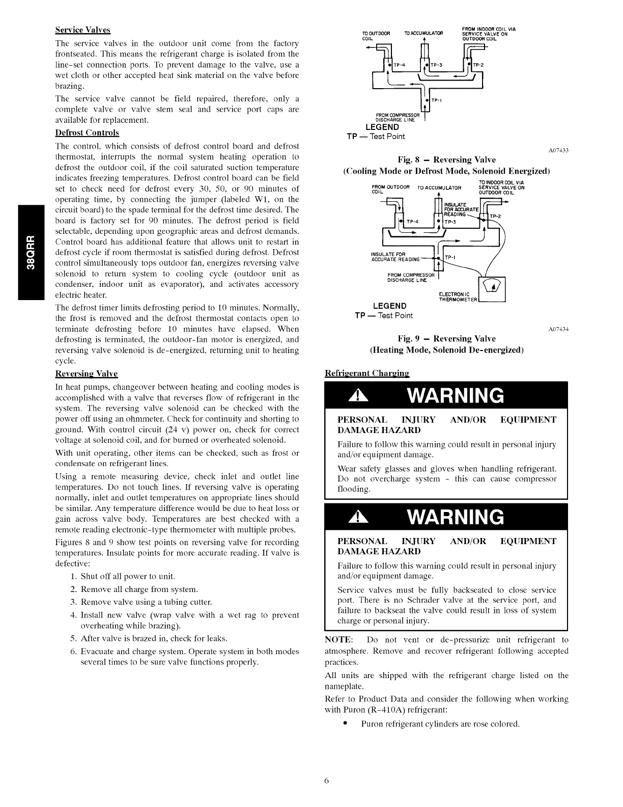
Reversing Valve
In heat pumps, changeover between heating and cooling modes is
accomplished with a valve that reverses flow of refrigerant in the
system. The reversing valve solenoid can be checked with the
power off using an ohmmeter. Check for continuity and shorting to
ground. With control circuit (24 v) power on, check for correct
voltage at solenoid coil, and for burned or overheated solenoid.
With unit operating, other items can be checked, such as frost or
condensate on refrigerant lines.
Using a remote measuring device, check inlet and outlet line
temperatures. Do not touch lines. If reversing valve is operating
normally, inlet and outlet temperatures on appropriate lines should
be similar. Any temperature difference would be due to heat loss or
gain across valve body. Temperatures are best checked with a
remote reading electronic-type thermometer with multiple probes.
Figures 8 and 9 show test points on reversing valve for recording
temperatures. Insulate points for more accurate reading. If valve is
defective:
1. Shut off all power to unit.
2. Remove all charge from system.
3. Remove valve using a tubing cutter.
4. Install new valve (wrap valve with a wet rag to prevent
overheating while brazing).
5. After valve is brazed in, check for leaks.
6. Evacuate and charge system. Operate system in both modes
several times to be sure valve functions properly.
FROM INDOOR COIL VIA
TO OUTDOOR TO ACCUMULATOR SERVICE VALVE ON
LEGEND
TP -- Test Point
A07433
Fig. 8 -Reversing Valve
(Cooling Mode or Defrost Mode, Solenoid Energized)
TO INOOOR COIL VIA
FROM OUTDOOR TO ACCUMULATOR SERVICE VALVE ON
COIL OUTDOOR COIL
INSULATE
FOR ACCURATE
READING TP-2
TP-4 TP'3
INSULATE FOR
ACCURATE READING
FROM COMPRESSOR
DISCHARGE LINE
ELECTRON IC
LEGEND
TP -- Test Point
A07434
Fig. 9 -Reversing Valve
(Heating Mode, Solenoid De-energized)
Refrigerant Char_in_
PERSONAL INJURY AND/OR EQUIPMENT
DAMAGE HAZARD
Failure to follow this warning could result in personal iniury
and/or equipment damage.
Wear safety glasses and gloves when handling refrigerant.
Do not overcharge system - this can cause compressor
flooding.
PERSONAL INJURY AND/OR EQUIPMENT
DAMAGE HAZARD
Failure to follow this warning could result in personal iniury
and/or equipment damage.
Service valves must be fully backseated to close service
port. There is no Schrader valve at the service port, and
failure to backseat the valve could result in loss of system
charge or personal iniury.
NOTE: Do not vent or de-pressurize unit refrigerant to
atmosphere. Remove and recover refrigerant following accepted
practices.
All units are shipped with the refrigerant charge listed on the
nameplate.
Refer to Product Data and consider the following when working
with Puron (R-410A) refrigerant:
• Puron refrigerant cylinders are rose colored.
•Recovery cylinder service pressure rating must be 400
psig, DOT (Department of Transportation) 4BA400 or
DOT BW400.
• Puron systems should be charged with liquid refrigerant.
Use a commercial type metering device in the manifold
hose when charging into suction line with compressor op-
erating.
• Manifold sets should be 700 psig high side and 180 psig
low side with 550 psig low-side retard,
• Use hoses with 700 psig service pressure rating.
• Puron refrigerant, as with other HFCs, is only compatible
with POE oils.
• Vacuum pumps will not remove moisture from oil.
• Polyol Ester oils absorb moisture rapidly, Do not expose oil
to atmosphere,
• Polyol Ester oils may cause damage to certain plastics and
roofing materials,
• Wrap all filter driers and service valves with wet cloth when
brazing.
• factory approved, liquid-line filter drier is required on ev-
ery unit,
• Do not use a TXV (thermostatic expansion valve) designed
for use with R-22 refrigerant. Refer to separate indoor unit
installation instructions for more details,
• If using a suction line drier, do not leave in place for more
than 72 hours,
Heating Check Chart Procedure - Heating Mode
To check system operation during heating cycle, refer to the
Heating check Chart on outdoor unit. This chart indicates whether
a correct relationship exists between system operating pressure and
air temperature entering indoor and outdoor units. If pressure and
temperature do not match on chart, system refrigerant charge may
not be correct. Do not use chart to adjust refrigerant charge.
NOTE: When charging is necessary during heating season, charge
nmst be weighed in accordance with unit rating plate ---0.6 oz./ft, of
3/8-in. liquid line above or below 25 ft. (7.6 m) respectively.
To calculate additional charge required for a 35-ft. (11 m) line set:
35 ft. (10.6 m) - 25 ft. (7.6 m) = 10 ft. X 0.6 oz./ft. = 6 oz. of
additional charge.
CHECK CHARGE - UNITS WITH TXV COOLING
METERING DEVICE
Factory charge amount and desired subcooling are shown on unit
rating plate. Charging method is shown on information plate inside
unit. To properly check or adjust charge, conditions must be
favorable for subcooling charging. Favorable conditions exist
when the outdoor temperature is between 70°F and 100°F (21°C
and 38°C), and the indoor temperature is between 70°F and 80°F
(21°C and 27°C). Follow the procedure below:
Unit is factory charged for 15 ft (4.6 m) of line-set. Adjust charge
by adding or removing 0.6 oz/ft of 3/8 liquid line above or below
15 ft (4.6 m) respectively.
For standard refrigerant line lengths (80 ft/24 m or less), allow
system to operate in cooling mode at least 15 nfinutes. If conditions
are favorable, check system charge by subcooling method. If any
adjustment is necessary, adjust charge slowly and allow system to
operate for 15 nfinutes to stabilize before declaring a properly
charged system.
If the indoor temperature is above 80°F (27°C), and the outdoor
temperature is in the favorable range, adjust system charge by
weight based on line length and allow the indoor temperature to
drop to 80°F (27°C) before attempting to check system charge by
subcooling method as described above.
If the indoor temperature is below 70°F (21°C), or the outdoor
temperature is not in the favorable range, adjust charge for line set
length above or below 15 ft (4.6 m) only. Charge level should then
be appropriate for the system to achieve rated capacity. The charge
level could then be checked at another time when the both indoor
and outdoor temperatures are in a more favorable range.
NOTE: If line length is beyond 80 ft (24.4 m) or greater than 20 ft
(6 m) vertical separation, See Long Line Guideline for special
charging requirements.
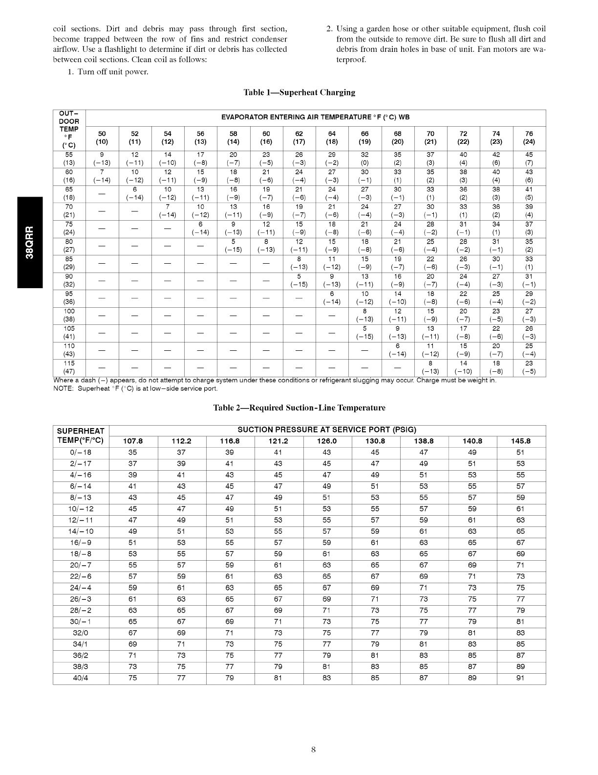
Units with Indoor Pistons
Units installed with indoor pistons require charging by the
superheat method. The following procedure is valid when indoor
airflow is within ---21% of its rated CFM.
1. Operate unit a minimum of 10 nfinutes before checking
charge.
2. Measure suction pressure by attaching an accurate gauge to
suction valve service port.
3. Measure suction temperature by attaching an accurate
thernfistor type or electronic thernmmeter to suction line at
service valve.
4. Measure outdoor air dry-bulb temperature with
thernmmeter.
5. Measure indoor air (entering indoor coil) wet-bulb
temperature with a sling psychrometer.
6. Refer to Table 1. Find outdoor temperature and evaporator
entering air wet-bulb temperature. At this intersection, note
superheat.
7. Refer to Table 2. Find superheat temperature located in item
6 and suction pressure. At this intersection, note suction line
temperature.
8. If unit has a higher suction line temperature than charted
temperature, add refrigerant until charted temperature is
reached.
9. If unit has a lower suction line temperature than charted
temperature, reclaim refrigerant until charted temperature is
reached.
10. When adding refrigerant, charge in liquid form into suction
service port using a flow-restricting device.
11. If outdoor air temperature or pressure at suction valve
changes, charge to new suction line temperature indicated
on chart.
MAINTENANCE
ELECTRICAL SHOCK HAZARD
Failure to follow this warning could result in personal
injury or death.
Before installing, modifying, or servicing system, main
electrical disconnect switch must be in the OFF
position. There may be more than 1 disconnect switch.
Lock out and tag switch with a suitable warning label.
LUBRICATION
Compressor
Compressor contains factory oil charge; replace oil when lost. Use
Mobile 3MA-POE oil.
CLEANING COILS
Coil should be washed out with water or blown out with
compressor air. Note that the blow-thru design causes dirt and
debris to build up on the inside of the coils. Clean coil annually or
as required by location and outdoor air conditions. Inspect coil
monthly and clean as required. Fins are not continuous through
coilsections.Dirtanddebrismaypassthroughfirstsection,
becometrappedbetweentherowof finsandrestrictcondenser
airflow.Useaflashlighttodetermineif dirtordebrishascollected
betweencoilsections.Cleancoilasfollows:
1.Turnoffunitpower.
2.Usingagardenhoseorothersuitableequipment,flushcoil
fromtheoutsidetoremovedirt.Besuretoflushalldirtand
debrisfromdrainholesinbaseofunit.Fanmotorsarewa-
terproof.
Table1--SuperheatCharging
OUT- EVAPORATOR ENTERING AIR TEMPERATURE °F(°C) WB
DOOR
TEMP
°F 50 52 54 56 58 60 62 64 66 68 70 72 74 76
(°C) (10) (11) (12) (13) (14) (16) (17) (18) (19) (20) (21) (22) (23) (24)
55 9 12 14 17 20 23 26 29 32 35 37 40 42 45
(13) (-13) (-11) (-10) (-8) (-7) (-5) (-3) (-2) (0) (2) (3) (4) (6) (7)
60 7 10 12 15 18 21 24 27 30 33 35 38 40 43
(16) (-14) (-12) (-11) (-9) (-8) (-6) (-4) (-3) (-1) (1) (2) (3) (4) (6)
65 6 10 13 16 19 21 24 27 30 33 36 38 41
(18) (-14) (-12) (-11) (-9) (-7) (-6) (-4) (-3) (-1) (1) (2) (3) (5)
70 7 10 13 16 19 21 24 27 30 33 36 39
(21) (-14) (-12) (-11) (-9) (-7) (-6) (-4) (-3) (-1) (1) (2) (4)
75 6 9 12 15 18 21 24 28 31 34 37
(24) (-14) (-13) (-11) (-9) (-8) (-6) (-4) (-2) (-1) (1) (3)
80 5 8 12 15 18 21 25 28 31 35
(27) (-15) (-13) (-11) (-9) (-8) (-6) (-4) (-2) (-1) (2)
85 8 11 15 19 22 26 30 33
(29) (-13) (-12) (-9) (-7) (-6) (-3) (-1) (1)
90 5 9 13 16 20 24 27 31
(32) (-15) (-13) (-11) (-9) (-7) (-4) (-3) (-1)
95 6 10 14 18 22 25 29
(36) (-14) (-12) (-10) (-8) (-6) (-4) (-2)
100 8 12 15 20 23 27
(38) (-13) (-11) (-9) (-7) (-5) (-3)
105 5 9 13 17 22 26
(41) (-15) (-13) (-11) (-8) (-6) (-3)
110 6 11 15 20 25
(43) (-14) (-12) (-9) (-7) (-4)
115 8 14 18 23
(47) (- 13) (- 10) (- 8) (- 5)
Where a dash (-) appears, do not attempt to charge system under these conditions or refrigerant slugging may occur. Charge must be weight in.
NOTE: Superheat °F (°C) is at low-side service port.
Table 2--Required Suction-Line Temperature
SUPERHEAT SUCTION PRESSURE AT SERVICE PORT (PSIG)
TEMP(°F/°C) 107,8 112,2 116,8 121,2 126,0 130,8 138,8 140,8 145,8
0/- 18 35 37 39 41 46 45 47 49 51
2/- 17 37 39 41 43 45 47 49 51 56
4/- 16 39 41 46 45 47 49 51 56 55
6/- 14 41 46 45 47 49 51 56 55 57
8/- 16 46 45 47 49 51 56 55 57 59
10/- 12 45 47 49 51 56 55 57 59 61
12/- 11 47 49 51 56 55 57 59 61 66
14/- 10 49 51 56 55 57 59 61 66 65
16/- 9 51 56 55 57 59 61 63 65 67
18/- 8 56 55 57 59 61 63 65 67 69
20/- 7 55 57 59 61 66 65 67 69 71
22/- 6 57 59 61 63 65 67 69 71 73
24/- 4 59 61 66 65 67 69 71 76 75
26/- 3 61 63 65 67 69 71 73 75 77
28/- 2 66 65 67 69 71 76 75 77 79
30/- 1 65 67 69 71 76 75 77 79 81
32/0 67 69 71 76 75 77 79 81 86
34/1 69 71 76 75 77 79 81 86 85
36/2 71 76 75 77 79 81 86 85 87
38/3 73 75 77 79 81 83 85 87 89
40/4 75 77 79 81 86 85 87 89 91
TROUBLESHOOTING
[
COMPRESSOR ]WILL NOT RUN
1
CONTACT OPEN
...t DEFECTIVE LOW-
VOLTAGE
TRANSFORMER
.._ CONTACTOR
COIL OPEN OR
SHORTED
OPENIN[_ORTHERMOSTAT
_._ LIQUID-LINE
PRESSURE
SWITCH OPEN
m_LOSS OF CHARGE
_{ OPEN CONTROL ]CIRCUIT
[
-_[ CONTADTORCLOSED
_. OMPRESSOR
POWER SUPPLY
OPEN
_[ LOOSE LEADS ATCOMPRESSOR
_[ FAULTY START
GEAR (1PH)
•"_ COMPRESSORSTUCK
._ COMPRESSOR
INTERNAL
OVERLOAD OPEN
.__'OPEN, SHORTED' t
OR GROUNDED
COMPRESSOR
MOTOR
| WtNOtN_S__J
"_ DEFECTIVE RUN 1CAPACITOR
I
COMPRESSOR
RUNS BUT
-- CYCLES ON
INTERNAL
OVERLOAD
_'_" DIRTY FILTERS l
OR INDOOR COtL
_[ INDOOR FAN DEFECTIVE FAN
STOPPED OR MOTOR
CYCLING ON CAPACITOR
OVERLOAD
4°-°1 l
REVERSING LOOSE LEADS AT
VALVE FAN MOTOR
4L RESTRICTION tN FAN MOIOR
DISCHARGE LINE BURNED OUT
_.{_ OVERCHARGE i
OR NON-
CONDENSABLES
IN SYSTEM
REFRIGERANT
CHARGE
UNE VOLTAGE
TOO HIGH OR
LOW
,_[ DEPBDTIVB RUN
CAPACITOR
(1 -PH)
._ COMPRESSOR
BEARINGS
FAULTY
-_ HIGH*LOADCONDmON
VALVE JAMMED
tN MIDPOSITION
NO HEATING OR
INSUFFICIENT
HEATING
T
HIGH ]SUPERHEAT
LOW SUCTION
LOW HEAD
I
__.____J
.__[ LOOSE LEADS AT 1
OUTDOOR PAN
MOTOR
_{ INTERNAL
FAN MOTOR
OVERLOAD
OPEN
FAN MOTORBURNED OUT
_[ DEFROST RELAY
NC
CONTACTS OPEN
ON CIRCUIT
BOARD
FAN MOTOR t
CONTACTS
WELDED CLOSED
IN DEFROST
RELAY
REVERSING
VALVE DID NOT
SHIFT
UNIT NOT
PROPERLY
CHARGED
COMPRESSOR 1
RUNS
INSUFFICIENT
HEATING
i
k
_[ OUTDOOR FANRUNNING
REVERSING
VALVE STUCK
_[ RESTRICTEDLIQUID LINE
_[ ACCURATER®
PISTON
_RESTRICTED
OR CLOGGED
UNDER*
CHARGED
_[ OUTDOOR COIL 1DIRTY
'_ STRAINERRESTRICTED
OUTDOOR COIL ]
J
HEAVtLY
FROSTED
_[ DEFECTIVE
DEFROST
TRERMDSTAT
f DEFROST
THERMOSTATIN
POOR PHYSICAL
CONTACT WITH
TUBE
-_ DEFECTIVEC_RGUtTBOARD
BAD ELECTRICAL l
CONNECTION
ANYWHEREIN
DEFROST CIRCUIT
11
-- STRIP HEATERS
NOT OPERATING ]
DOT SETTING
TOO LOW
CAP TUBE
PINCHED OR
BULB NOT
SENSING TRUE
OUTDOOR TEMP
_[ STRIP HEATER
RELAY OR
CONTACTOR
DEFECTIVE
OPENINGIN ]
POWER CIRCUIT
TO HEATER
_ENTS
BROKEN FUSE
LINK
_ BRGKEN HEATER ]ELEMENT
__[ OPEN OVER- I
TEMPERATURE
THERMOSTAT
-DEFECTIVE ROOM
(T2HNEDRM TOASTE_)T._
LEGEND
NC -- Normally Closed
ODT -- Outdoor Thermostat
NOTE: For systems with indoor units equipped with microprocessor
control, see separate controls, service, and troubleshooting manual.
Fig. 10 - Troubleshooting the Cooling Cycle
A07435
TROUBLESHOOTING (CONT.)
[
I COMPRESSOR i
WILL NOT RUN
I
[ !
__{ DEFECTIVE
LOW-VOLTAGE
TRANSFORMER
_{_ OPEN CONTROL ]CIRCUIT
_-[ LOSS OF CHARGE ]
_[_ LOOSE
ELECTRICAL
CONNECTION
COMPRESSOR ]
POWER SUPPLY
OPEN
"_[ LOOSE LEADS AT ]COMPRESSOR
FAULTY START
GEAR (!-PH)
_[ OPEN, SHORTED,
OR GROUNDED
COMPRESSOR
MOTOR
WINDINGS
q COMPRESSOR
STUCK
__ COMPRESSOR
INTERNAL
PROTECTION
OPEN
-_ DEFECTIVE RUN ]CAPAC_OR
NO COOLING OR ]
INSUFFiCiENT
COOLING
I
t
COMPRESSOR
RUNS BUT
CYCLES ON
INTERNAL
OVERLOAD
OUTDOOR FAN jL_
STOPPED OR
CYCUNGON
OVERLOAD
_[ OUTDOOR AIR 1
RESTRICTED OR
RECIF_CULATING
DAMAGED OR
STUCK
REVERSING
VALVE
_{ RESTRICTEDDISCHARGE TUBE
--_ LOOSE LEAD AT IFAN MOTOR
=_ DEFROST RELAYS ]
NC CONTACTS
OPEN
•_[ MOTORDEFECTIVE
_{INOORRECT OFM ]CAPACITOR
£
LOW SUCTION 1PRESSURE
_-[ DIRTY AIR
FILTERS
-_ DUCTRESTRICTED
DAMPERS }PARTLY CLOSED
l
COMPRESSOR
RUNS BUT
INSUFFICIENT
COOLING
l HIGH SUCTION
LOW READ
PRESSURE
__[
._ REVERSING
VALVE HUNG UP
OR INTERNAL
LEAK
DEFECTIVE
COMPRESSOR
VALVES
1
I RIGRSUOTiDN1LOW SUPERHEAT
__]
[_ UNIT
OVERCHARGED 1
1 'NCORRECT 1
ACCURATER
PISTON
==_ _NTERNAL 1
PRESSURE
RELIEF OPEN
___ OVERGHARGE
OR NON-
CONDENSABLES
IN SYSTEM
LOW
REFRIGERANT
CHARGE
_{_ LINE VOLTAGE
TOO HIGH OR
LOW
__{ DEFECTIVE
DEFPOST
THERMOSTAT
DEFECTIVE RUN t
CAPAC_OR
___ COMPRESSOR ]
BEARINGS
=¢ULTY
*-_ INDOOR COIL ]FROSTED
LIQUID LINE 1
SLIGHTLY
RESTRICTED
ACCURATEN®
RESTRICTED
__[ INCORRECT I
ACCURATER
PISTON
IN DOOR COiL
STRAINER
RESTRICTED
LEGEND
NC -- Normally Closed
ODT -- Outdoor Thermostat
NOTE: For systems with indoor units equipped with microprocessor
control, see separate controls, service, and troubleshooting manual.
INDOOR BLOWER l
MOTOR
DEFECTIVE OR
CYCLING ON
OVERLOAD
Fig. 11 - Troubleshooting the Heating Cycle
A07436
Always Ask For
Copyright 2010 Carrier Corp. *7310 W. Morris St. *Indianapolis, IN 46231 Printed in U.S.A. Edition Date:07/i0
Manufacturer reserve8 the right to change, at any time, specification8 and design8 without notice and without obligations.
10
Catalog No: 38QRR-6Sl
Replaces: 38QRR-5SI
