Carrier 48XP024040300 User Manual CENTRAL PACKAGE Manuals And Guides L0907192
CARRIER Package Units(both units combined) Manual L0907192 CARRIER Package Units(both units combined) Owner's Manual, CARRIER Package Units(both units combined) installation guides
User Manual: Carrier 48XP024040300 48XP024040300 CARRIER CENTRAL PACKAGE - Manuals and Guides View the owners manual for your CARRIER CENTRAL PACKAGE #48XP024040300. Home:Heating & Cooling Parts:Carrier Parts:Carrier CENTRAL PACKAGE Manual
Open the PDF directly: View PDF ![]() .
.
Page Count: 30
®
Turn to the Expertg
Installation Instructions
NOTE: Read the entire instruction manual before starting the
installation.
NOTE: Installer: Make sure the Owner's Manual and Service
Instructions are left with the unit after installation,
TABLE OF CONTENTS
PAGE
SAFETY CONSIDERATIONS ......................... 1
INTRODUCTION ................................... 2
RECEIVING AND INSTALLATION ................. 2-13
Check Equipment .................................. 2
Identify Unit .................................... 2
Inspect Shipment ................................. 2
Provide Unit Support ............................... 2
Roof Curb ...................................... 2
Slab Mount ..................................... 2
Ground Mount .................................. 2
Field Fabricate Ductwork ............................ 2
Provide Clearances ................................. 2
Rig and Place Unit ................................. 4
Connect Condensate Drain ........................... 6
Install Flue Hood ................................... 7
Install Gas Piping .................................. 7
Install Duct Connections ............................. 9
Configuring Units for Downflow (Vertical)
Discharge ...................................... 9
Install Electrical Connections ........................ 10
High-Voltage Connections ........................ 10
Special Procedures for 208-V Operation .............. 11
Control Voltage Connections ....................... 11
Easy Select TM . .................................. 11
Transformer Protection ........................... 14
PRE-START-UP ................................... 14
START-UP ..................................... 14-21
Check for Refrigerant Leaks ......................... 14
Unit Sequence of Operation ......................... 14
48XP Sequence of Operation ...................... 14
Start-Up Heating & Make Adjustments ................ 15
Check Heating Control ........................... 15
Check Gas Input ................................ 15
Adjust Gas Input ................................ 15
Check Burner Flame ............................. 16
Airflow and Temperature Rise ...................... 16
Heating Sequence of Operation ..................... 16
Limit Switches ................................. 16
Rollout Switch ................................. 17
Start-Up Cooling & Make Adjustments ................ 17
Checking Cooling Control Operation ................ 17
Checking & Adjusting Refrigerant Charge ............ 21
Indoor Airflow and Airflow Adjustments ............. 21
MAINTENANCE ................................ 22-25
Air Filter ........................................ 22
Evaporator Blower and Motor ........................ 22
Flue Gas Passageways .............................. 22
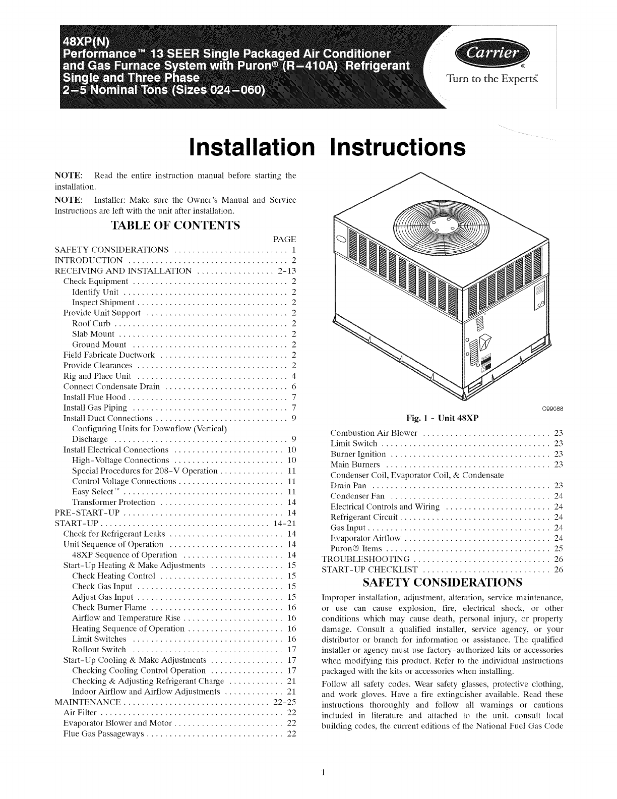
C99088
Fig. 1 - Unit 48XP
Combustion Air Blower ............................ 23
Limit Switch ..................................... 23
Burner Ignition ................................... 23
Main Burners .................................... 23
Condenser Coil, Evaporator Coil, & Condensate
Drain Pan ....................................... 23
Condenser Fan ................................... 24
Electrical Controls and Wiring ....................... 24
Refrigerant Circuit ................................. 24
Gas Input ........................................ 24
Evaporator Airflow ................................ 24
Puron® Items .................................... 25
TROUBLESHOOTING .............................. 26
START-UP CHECKLIST ............................ 26
SAFETY CONSIDERATIONS
Improper installation, adjustment, alteration, service maintenance,
or use can cause explosion, fire, electrical shock, or other
conditions which may cause death, personal injury, or property
damage. Consult a qualified installer, service agency, or your
distributor or branch for information or assistance. The qualified
installer or agency must use factory-authorized kits or accessories
when modifying this product. Refer to the individual instructions
packaged with the kits or accessories when installing.
Follow all safety codes. Wear safety glasses, protective clothing,
and work gloves. Have a fire extinguisher available. Read these
instructions thoroughly and follow all warnings or cautions
included in literature and attached to the unit. consult local
building codes, the current editions of the National Fuel Gas Code
(NFGC)NFPA54/ANSIZ223A,andthe National Electrical Code
(NEC) NFPA 70.
In Canada refer to the current editions of the National Standards of
Canada CAN/CSA-BI49.1 and .2 Natural Gas and Propane
Installation codes, and Canadian Electrical Code CSA C22A
Recognize safety information. This is the safety-alert symbol Z_
When you see this symbol on the unit and in instructions or manu-
als, be alert to the potential for personal injury. Understand these
signal words: DANGER, WARNING, and CAUTION. These
words are used with the safety-alert symbol. DANGER identifies
the most serious hazards which will result in severe personal injury
or death. WARNING signifies hazards which could result in per-
sonal injury or death. CAUTION is used to identify unsafe practic-
es which may result in minor personal injury or product and prop-
erty damage. NOTE is used to highlight suggestions which will
result in enhanced installation, reliability, or operation.
ELECTRICALSHOCK HAZARD
Failure to follow this warning could result in personal
injury or death.
Before installing or servicing system, always turn off and
tag lockout main power to system. There may be more
than one disconnect switch. Turn off accessory heater power
switch if applicable.
FIRE, EXPLOSION, ELECTRICAL SHOCK AND
CARBON MONOXIDE POISONING HAZARD
Failure to follow this warning could result in personal
injury, death or property damage.
A qualified installer or agency must use only
factory-authorized kits or accessories when modifying this
product.
INTRODUCTION
The 48XP unit (see Fig. 1) is a fully self-contained, combination
Category I gas heating/electric cooling unit designed for outdoor
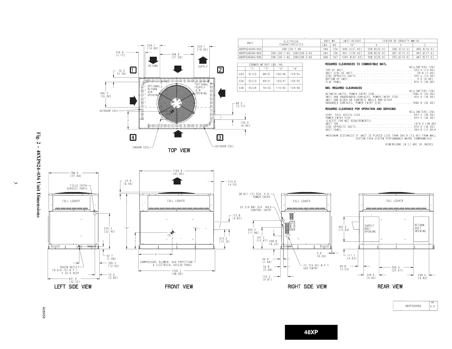
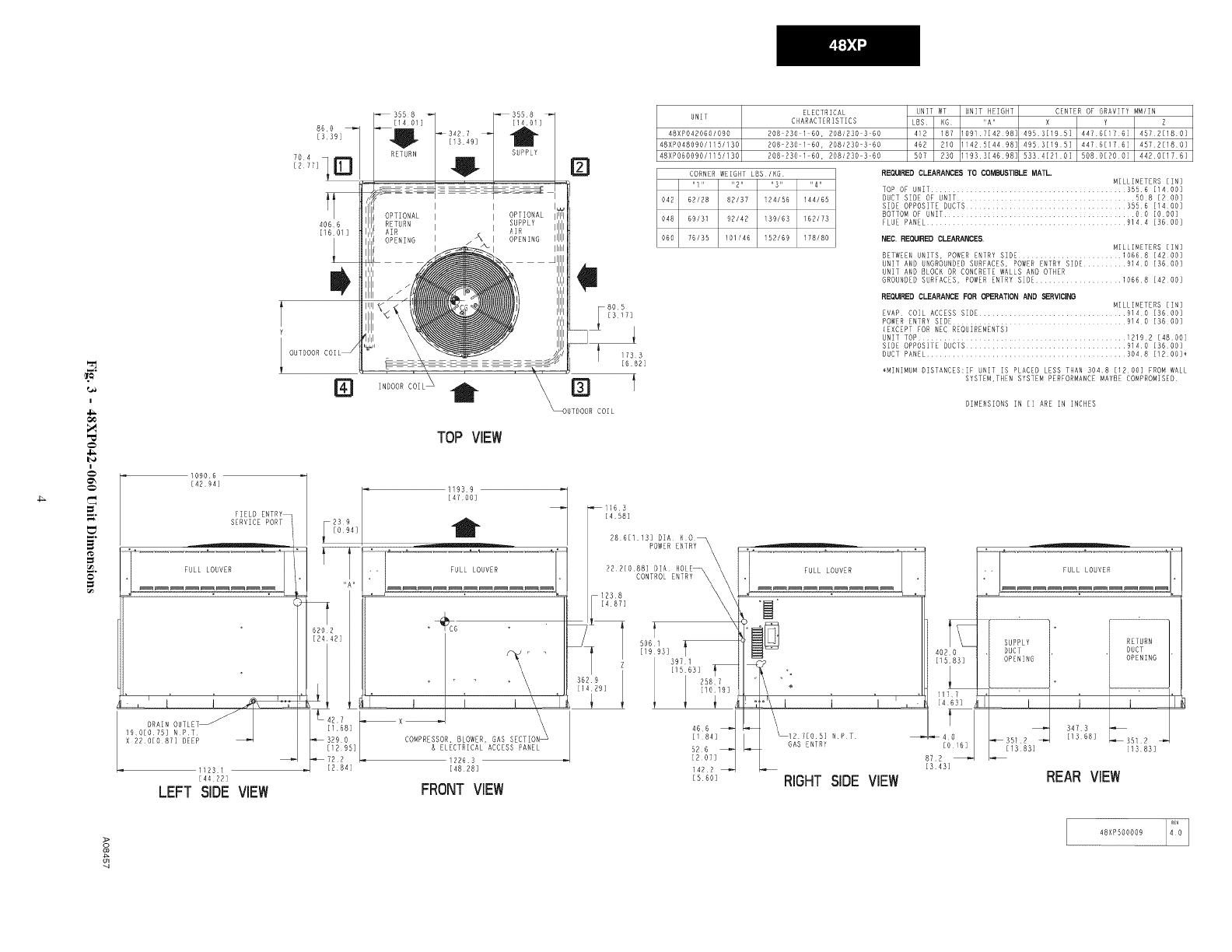
installation (See Fig. 2 and 3 for unit dimensions). All unit sizes
have return and discharge openings for both horizontal and
downflow configurations, and are factory shipped with all
downflow duct openings covered. Units may be installed either on
a rooftop, a cement slab, or directly on the ground, if local codes
permit (See Fig. 4 for roof curb dimensions).
Models with an N in the fifth position of the model number are
dedicated Low NOx units designed for California installations.
These models meet the California maximum oxides of nitrogen
(NOx) emissions requirements of 40 nanograms/joule or less as
shipped from the factory and must be installed in California Air
Quality Management Districts or any other regions in North
America where a Low NOx rule exists.
RECEIVING AND INSTALLATION
Step 1-- Check Equipment
IDENTIFY UNIT
The unit model number and serial number are stamped on the unit
information plate. Check this information against shipping papers.
INSPECT SHIPMENT
Inspect for shipping damage while unit is still on shipping pallet. If
unit appears to be damaged or is torn loose from its anchorage,
have it examined by transportation inspectors before removal.
Forward claim papers directly to transportation company.
Manufacturer is not responsible for any damage incurred in transit.
Check all items against shipping list. Immediately notify the
nearest equipment distribution office if any item is missing. To
prevent loss or damage, leave all parts in original packages until
installation.
Step 2 -- Provide Unit Support
For hurricane tie downs, contact distributor for details and PE
(Professional Engineering) Certificate if required.
ROOF CURB
Install accessory roof curb in accordance with instructions shipped
with curb (See Fig. 4). Install insulation, cant strips, roofing, and
flashing. Ductwork must be attached to curb.
IMPORTANT: The gasketing of the unit to the roof curb is
critical for a water tight seal. Install gasketing material supplied
with the roof curb. Improperly applied gasketing also can result in
air leaks and poor unit performance.
Curb should be level to within 1/4 in. (6 mm). This is necessary for
unit drain to function properly. Refer to accessory roof curb
installation instructions for additional information as required.
SLAB MOUNT
Place the unit on a solid, level concrete pad that is a minimum of 4
in. (102 mm) thick with 2 in. (51 mm) above grade. The slab
should be flush on the compressor end of the unit (to allow
condensate drain installation) and should extend 2 in. (51 mm) on
the three remaining sides of the unit. Do not secure the unit to the
slab except when required by local codes.
GROUND MOUNT
The unit may be installed either on a slab or placed directly on the
ground, if local codes permit. Place the unit on level ground
prepared with gravel for condensate discharge.
Step 3-- Field Fabricate Ductwork
Secure all ducts to roof curb and building structure on vertical
discharge units. Do not connect ductwork to unit. For horizontal
applications, unit is provided with flanges on the horizontal
openings. All ductwork should be secured to the flanges. Insulate
and weatherproof all external ductwork, joints, and roof openings
with counter flashing and mastic in accordance with applicable
codes.
Ducts passing through an unconditioned space must be insulated
and covered with a vapor barrier.
If a plenum return is used on a vertical unit, the return should be
ducted through the roof deck to comply with applicable fire codes.
A minimum clearance is not required around ductwork. Cabinet
return-air static shall not exceed -.25 IN. W.C..
Step 4-- Provide Clearances
The required minimum operating and service clearances are shown
in Fig. 2 and 3. Adequate combustion, ventilation and condenser
air must be provided in accordance with section 9.3, Air for
Combustion and Ventilation, of the National Fuel Gas Code
NFPA54/ANSI Z223.1 or applicable provisions of local building
code. In Canada, follow section 8 of Can/CSA-BI49.1
Installation Codes or applicable provisions of local building code.
IMPORTANT: Do not restrict outdoor airflow. An air restriction
at either the outdoor-air inlet or the fan discharge may be
detrimental to compressor life.
The condenser fan pulls air through the condenser coil and
discharges it through the top grille. Be sure that the fan discharge
does not recirculate to the condenser coil. Do not locate the unit in
either a corner or under an overhead obstruction. The minimum
clearance under a partial overhang (such as a normal house
overhang) is 48-in. (1219 mm) above the unit top. The maximum
horizontal extension of a partial overhang must not exceed 48-in.
(1219 mm)
Do not place the unit where water, ice, or snow from an overhang
or roof will damage or flood the unit. Do not install the unit on
carpeting or other combustible materials. The unit may be installed
on wood flooring or on Class A, B, or C roof covering materials.
I
m_
I
d_
798 5
[S 44]
FIELD ENTRY_
SERVICE PORTS i
19 O[O 15] NPT
X 220 DEER
_83 0
[32 72]
LEFT SIDE VIEW
It
406 5
[16 DOE
OUTDOOR
106 o
[4 17]
@ t
INDOOR COIL TOP VIEW
[4700]
FULL LOUVER
[168]
_3265
[1285]
_724
[285]
COMPRESSOR, 8LOWER, GAS PARTITIO
& ELECTRICAL ACCESS PANEL
12263
[A828]
FRONT VIEW
D
_UTDOOR COIL
UNIT
_8XPO2_04O/OGO
_SXPO3OO4O/OGO
_SXP036060/090
ELECTRICAL
CHARACTERISTICS
208 230 I 60
208 230 i 60, 2081230 3 60
208 230 i 60, 208/230 3 60
UNIT WT UNIT HEIGHT
LBS KG "A"
340 154 940,313702]
344 156
368 167
CENTER OF GRAVITY MM/IN
Y Z
368 B[i_5] 40641160]
55881220] 38741i53] 4470[176]
50801200] 55561i4 O] 44701176]
CORNER WEIGHT LBS/KG
"1 .... 2.... 3.... 4"
024 51123 68131 102146 119/54
030 52123 69/31 103/a7 120155
036 55124 74133 110150 129158
REQ_RED CLEARANCES TO COMBUSTIBLE MATL. MILLIMETERS [IN]
TO_ OF UNIT ............................ 3556 [1400]
DUCT SIDE OF UNIT ......................................... 508 [200]
SIDE OPPOSETE DUCTS..................................... 3556 [1400]
BOTTOM OF UNIT .............................. O0 [OOO]
FLUE PANEL .............................................. 9i44 [3600]
805
[317]
1533
[604]
t
NEC. REQUIRED CLEARANCES.
MILLIMETERS [IN]
BETWEEN UNITS, POWER ENTRY SIDE ........................ 10668 [4200]
UNIT AND UNGROUNDED SURFACES, POWER ENTRY SIDE ....... 9140 [36 ODE
UNIT AND BLOCK OR CONCRETE WALLS AND OTHER
GROUNDED SURFACES, DOWER ENTRY SIDE ................... i0668 [4200]
REQ_RED CLEARANCE FOR OPERATION AND SERVICINO MILLIMETERS [IN]
EVAP COIL ACCESS SIDE ....................... 91_ O [3600]
POWER ENTRY SIDE ........................................ 91_0 [3600]
(EXCEPT FOR NEC REQUIREMENTS)
UNIT TOP ........................................... 12192 [_800]
SIDE OPPOSITE DUCTS..................................... 9140 [3600]
DUCT PANEL ............................ 304 8 [1200]*
_MINIMUM DISTANCES:IF UNIT IS PLACED LESS THAN 3048 [1200] FROM WALL
SYSTEM,THEN SYSTEM PERFORMANCE MAYBE COMPROMISED
DIMENSIONS IN [] ARE IN INCHES
_I156
[455]
i238
[487]
3130
[1232]
222[088] DEA
t
456 R
[1796]
a68
[184]
52 8
[208]
1222
[48_]
[020]
NPT
L GAS ENTRY
RIGHT SIDE VIEW
L1177
[463]
898
[353]
m_:_RN
INING
iL__
[21 67]
!496
[983] [98B]
REARVIEW
o>
2
48XP500006
ml
I
m_
&
.=.
t_
_°
860
[339]
4066
[1601]
t
Y
1[ OUTBOOR
[i1
10906
[4294]
FIELD ENTRY
SERVECE PORT
FULL LOUVER EL
11231
[4422]
LEFT SIDE VIEW
INDOOR6OIL _. \N
TOP VIEW
• _ FULL LOUVER
[284]
_X_ \
COMPRESSOR, BLOWER, GAS SECTION _
& ELECTRICAL ACCESS PANEL
FRONT VIEW
805
[317]
733
[682]
[i1 t
ELECTRICAL
UNIT CHARACTERISTICS
48XP042060/090 208 230 1 60, 208/230 3 60
48XP048090/!15/i30 208 230 1 60, 208/R30 3 60
48XPO6009B/!lS!130 208 230 1 60, 208/230 3 60
UNIT WT UNIT HEIGHT CENTER OF GRAVITY MM/IN
LBS KG "A" X Z
412 181 1091714298: 4953[195] NB721180]
462 210 I1425[4498: 4953[195] 4476[176] 4572[180]
507 230 119331469B: 533412/0] 5BBB[ROO] 4420[176]
CORNER WEIGHT LBS/KG
"i .... 2 .... 3 .... 4"
042 62/28 82/37 124156 144/65
048 69/31 92/42 139/63 16R/73
060 76135 101146 152/69 178180
REO_PED CLEARANCES TO COMBUSTIBLE MATL.
MILLIMETERS [IN]
TOP OF UNET ............................................. 3596 [1400]
DUCT SEDE OF UNET ......................................... 508 [200]
SIDE OPPOSITE DUCTS ..................................... 3556 [1400]
BOTTOM OF UNET............................................ OO [OOO]
FLUE PANEL ............................... 914 4 [36 O0]
NEC. REQUIRED CLEARANCES.
MILLIMETERS [IN]
BETWEEN UNITS, POWER ENTRY SIDE ....................... 10668 [a20O]
UNIT AND UNGROUNDED SURFACES, POWER ENTRY SIBE .......... 9140 [3600]
UNIT AND BLOCK OR CONCRETE WALLS AND OTHER
GROUNDED SURFACES, POWER ENTRY SIDE .................... 10668 [4200]
REO_RED CLEARANCE FOR OPERATION AND ,SERVICING
MILLIMETERS [IN]
EVAP COIL ACCESS SEDE .................................. 9140 [3600]
ROWER ENTRY SEDE ............................ 914 O [3600]
(EXCEPT FOR NEC REQUIREMENTS)
oNIT TOP ....................................... 12192 [4800]
SIDE OPPOSITE DUCTS ..................................... 9140 [3600]
DUCT PANEL .............................................. 3048 [1200]_
_MINIMUM DESTANCES:ZF UNIT IS PLACED LESS THAN 3048 [1200] FROM WALL
SYSTEM,THEN SYSTEM PERFORMANCE MAYBE COMPROMISED
DIMENSIONS IN [] ARE IN INCHES
_1i63
[458]
28 61113] BIA N 0
POWER ENTRY\ \
f
506
[19 93]
466
[i 84]
526
[R07]
i422
[SGO] RIGHT SIDE VIEW
[016]
872
[343]
SUPPLY
DUCT .. .
[i3 83] [1383]
REAR VIEW
>
g
48XP500009
J base\ iiiiiiiiiiiiiiiiiiiiiiiiiiiiiiiiiiiiiiiiiiii_i!i!ii!ii!ii!ii!ii!i!!_!!_!!_!!_!i_i!_iii_ii_ii_ii_ii_ii_ii_ii_ii_i!!!!!_!!_!!i!i!i!ii!ii!iiiiiiiiiiiiiiiiiiiiiiiiiiiiiiiiiiiiiii!i!i!i!iiiiiiiiiiiiiiiiii_i_l_l......
J Screw _
/(NOTE A) _'_v
*Gasketing .._
/Wood \
Flashing.field II1_1 tl
II_s_n (f!eld I
I Roofing mate_al ll_i!_ II supplied)
\ f'_'dsuPP'ied-- - tl_iill IL
_, /IS_!II II-_Uuctwork /
\ _li II ,i_,dsupp,ed/
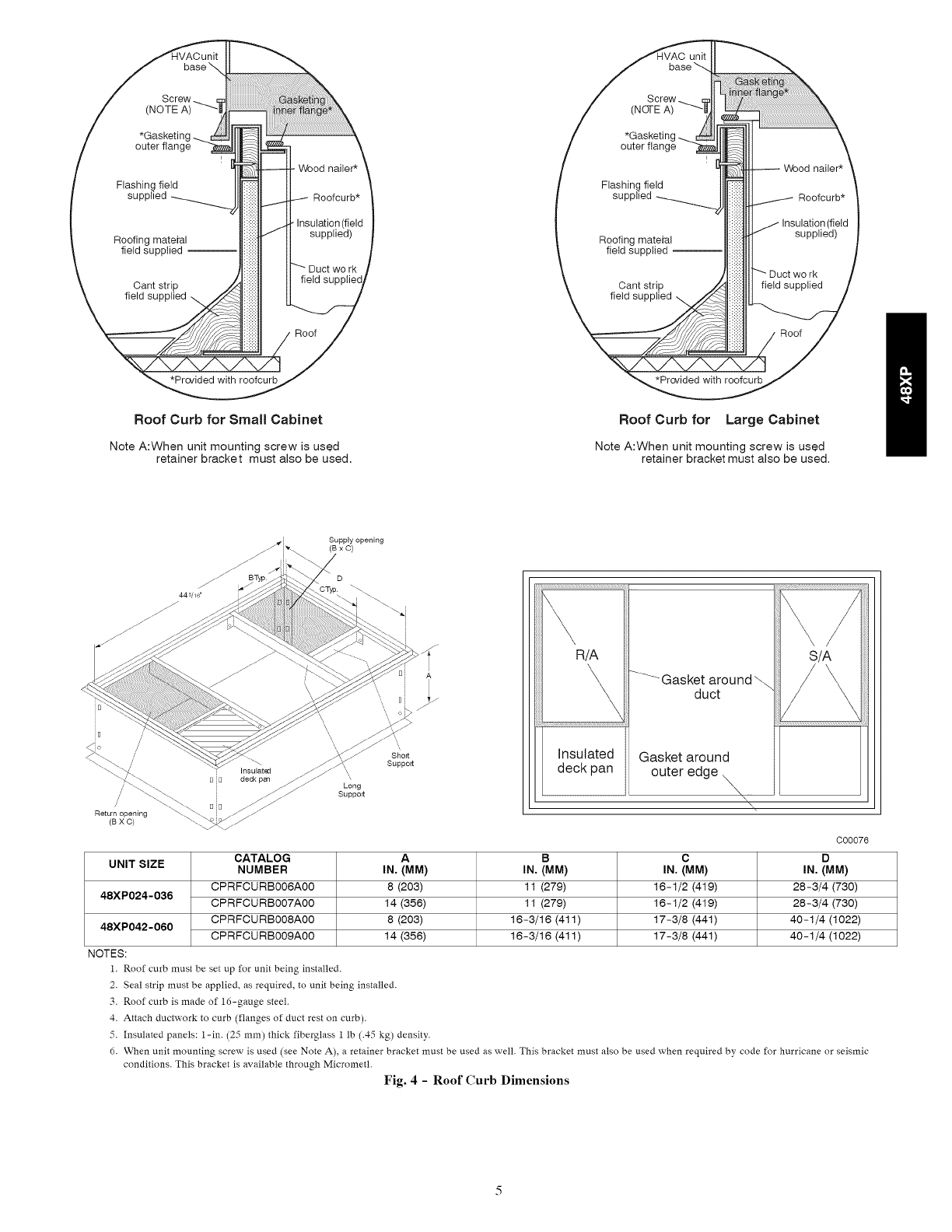
Roof Curb for Small Cabinet
Note A:When unit mounting screw is used
retainer bracket must also be used.
Roof Curb for Large Cabinet
Note A:When unit mounting screw is used
retainer bracket must also be used.
Supply opening
(BxC)
445/16"
R/A
\,\
Insulated
S/A
-'---'--GaSkec,tua_Ound. /_
Gasket around
deck pan outer edge
\
A B C
UNIT SIZE IN. (MM) IN. (MM) IN. (MM)
8 (203) 11 (279) 16-1/2 (419)
48XP024-036 14 (356) 11 (279) 16-1/2 (419)
48XP042-060 8 (203) 16-3/16 (411) 17-3/8 (441)
14 (356) 16-3/16 (411) 17-3/8 (441)
CATALOG
NUMBER
CPRFCURB006A00
CPRFCURB007A00
CPRFCURB008A00
CPRFCURB009A00
NOTES:
1. Roof curb must be set up for unit being installed.
C00076
D
IN, (MM)
28-3/4 (730)
28-3/4 (730)
40-1/4 (1022)
40-1/4 (1022)
2. Seal strip must be applied, as required, to unit being installed.
3. Roof curb is made of 16-gauge steel.
4. Attach ductwork to curb (flanges of duct rest on curb).
5. Insulated panels: 1-in. (25 mm) thick fiberglass 1 lb (.45 kg) density.
d. When unit mounting screw is used (see Note A), a retainer bracket must be used as well. This bracket must also be used when required by code for hurricane or seismic
conditions. This bracket is available through Micrometl.
Fig. 4 - Roof Curb Dimensions
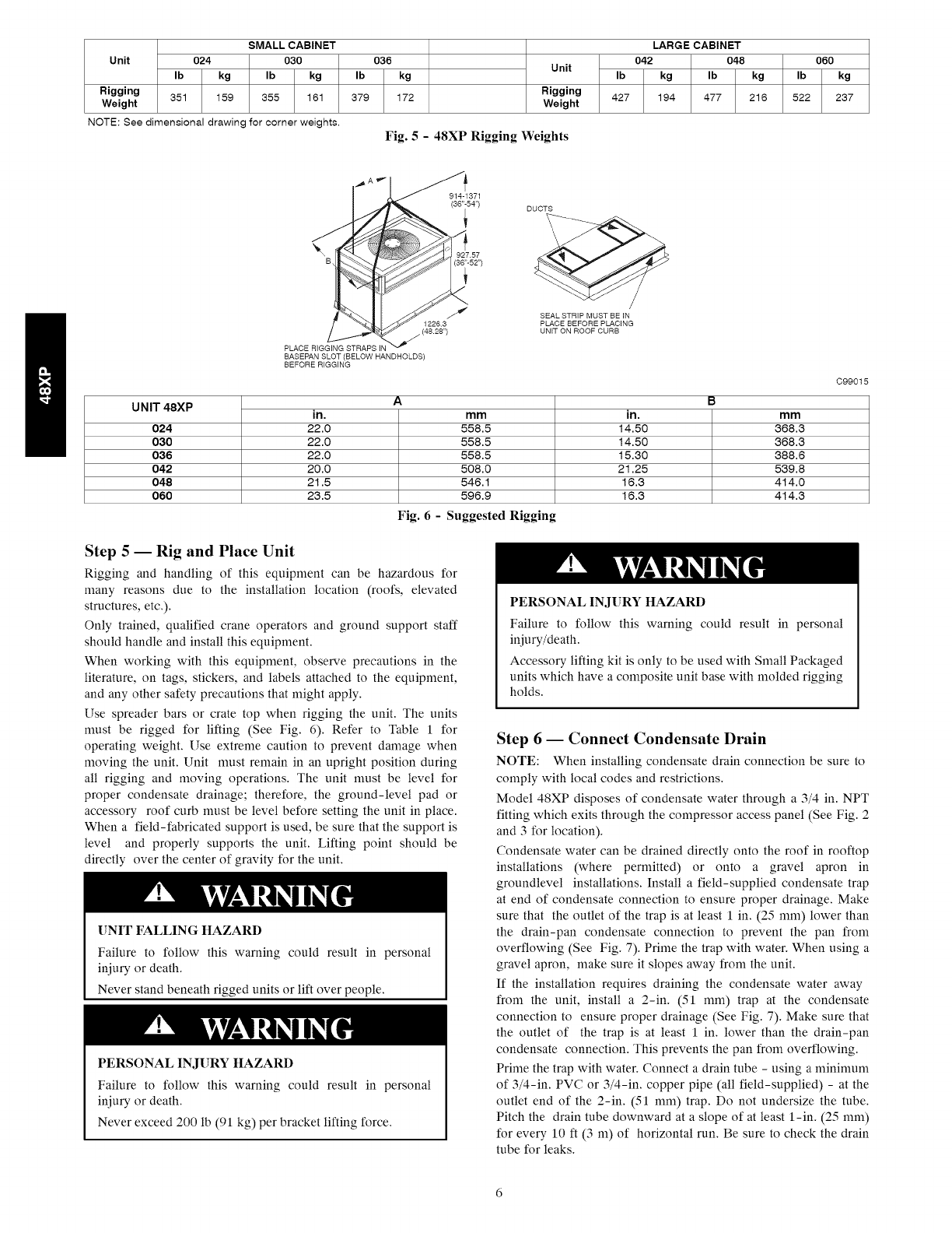
Unit
Rigging
Weight
SMALL CABINET
024 030 036
Ib kg Ib kg Ib kg
351 159 355 161 379 172
LARGE CABINET
042 048 060
Unit Ib kg Ib kg Ib kg
Rigging 427 194 477 216 522 237
Weight
NOTE: See dimensional drawing for corner weights.
Fig. 5 - 48XP Rigging Weights
BASEPAN SLOT (BELOW HANDHOLDS)
BEFORE RIGGING
DUCTS
SEAL STRIP MUST BE IN
PLACE BEFORE PLACING
UNIT ON ROOF CURB
UNIT 48XP A B
in. in. mm
024 22.0 14.50 368.3
030 22.0 14.50 368.3
036 22.0 15.30 388.6
042 20.0 21.25 539.8
048 21.5 16.3 414.0
060 23.5 16.3 414.3
mm
558.5
558.5
558.5
508.0
546.1
596.9
Fig. 6 - Suggested Rigging
C99015
Step 5 -- Rig and Place Unit
Rigging and handling of this equipment can be hazardous for
many reasons due to the installation location (roofs, elevated
structures, etc.).
Only trained, qualified crane operators and ground support staff
should handle and install this equipment.
When working with this equipment, observe precautions in the
literature, on tags, stickers, and labels attached to the equipment,
and any other safety precautions that might apply.
Use spreader bars or crate top when rigging the unit. The units
must be rigged for lifting (See Fig. 6). Refer to Table 1 for
operating weight. Use extreme caution to prevent damage when
moving the unit. Unit must remain in an upright position during
all rigging and moving operations. The unit must be level for
proper condensate drainage; therefore, the ground-level pad or
accessory roof curb must be level before setting the unit in place.
When a field-fabricated support is used, be sure that the support is
level and properly supports the unit. Lifting point should be
directly over the center of gravity for the unit.
UNIT FALLING HAZARD
Failure to follow this warning could result in personal
iniury or death.
Never stand beneath rigged units or lift over people.
PERSONAL INJURY HAZARD
Failure to follow this warning could result in personal
iniury or death.
Never exceed 200 lb (91 kg) per bracket lifting force.
PERSONAL INJURY HAZARD
Failure to follow this warning could result in personal
iniury/death.
Accessory lifting kit is only to be used with Small Packaged
units which have a composite unit base with molded rigging
holds.
Step 6-- Connect Condensate Drain
NOTE: When installing condensate drain connection be sure to
comply with local codes and restrictions.
Model 48XP disposes of condensate water through a 3/4 in. NPT
fitting which exits through the compressor access panel (See Fig. 2
and 3 for location).
Condensate water can be drained directly onto the roof in rooftop
installations (where permitted) or onto a gravel apron in
groundlevel installations. Install a field-supplied condensate trap
at end of condensate connection to ensure proper drainage. Make
sure that the outlet of the trap is at least 1 in. (25 mm) lower than
the drain-pan condensate connection to prevent the pan from
overflowing (See Fig. 7). Prime the trap with water. When using a
gravel apron, make sure it slopes away from the unit.
If the installation requires draining the condensate water away
from the unit, install a 2-in. (51 mm) trap at the condensate
connection to ensure proper drainage (See Fig. 7). Make sure that
the outlet of the trap is at least 1 in. lower than the drain-pan
condensate connection. This prevents the pan from overflowing.
Prime the trap with water. Connect a drain tube - using a minimum
of 3/4-in. PVC or 3/4-in. copper pipe (all field-supplied) - at the
outlet end of the 2-in. (51 mm) trap. Do not undersize the tube.
Pitch the drain tube downward at a slope of at least l-in. (25 mm)
for every 10 ft (3 m) of horizontal run. Be sure to check the drain
tube for leaks.
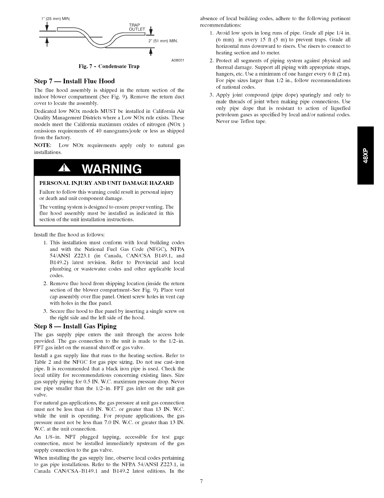
1" (25 mm) MIN.
._L TRAP
OUTLET Z
_..'__-j__ 2"(51 mm)M IN.
A08001
Fig. 7 -Condensate Trap
Step 7-- Install Flue Hood
The flue hood assembly is shipped in the return section of the
indoor blower compartment (See Fig. 9). Remove the return duct
cover to locate the assembly.
Dedicated low NOx models MUST be installed in California Air
Quality Management Districts where a Low NOx rule exists. These
models meet the California maximum oxides of nitrogen (NOx)
emissions requirements of 40 nanograms/joule or less as shipped
from the factory.
NOTE: Low NOx requirements apply only to natural gas
installations.
PERSONAL INJURY AND UNIT DAMAGE HAZARD
Failure to follow this warning could result in personal injury
or death and unit component damage.
The venting system is designed to ensure proper venting. The
flue hood assembly must be installed as indicated in this
section of the unit installation instructions.
absence of local building codes, adhere to the following pertinent
recommendations:
1. Avoid low spots in long runs of pipe. Grade all pipe 1/4 in.
(6 mm) in every 15 ft (5 m) to prevent traps. Grade all
horizontal runs downward to risers. Use risers to connect to
heating section and to meter.
2. Protect all segments of piping system against physical and
thermal damage. Support all piping with appropriate straps,
hangers, etc. Use a minimum of one hanger every 6 ft (2 m).
For pipe sizes larger than 1/2 in., follow recommendations
of national codes.
3. Apply joint compound (pipe dope) sparingly and only to
male threads of joint when making pipe connections. Use
only pipe dope that is resistant to action of liquefied
petroleum gases as specified by local and/or national codes.
Never use Teflon tape.
Install the flue hood as follows:
1. This installation must conform with local building codes
and with the National Fuel Gas Code (NFGC), NFPA
54/ANSI Z223.1 (in Canada, CAN/CSA B149.1, and
B149.2) latest revision. Refer to Provincial and local
plumbing or wastewater codes and other applicable local
codes.
2. Remove flue hood from shipping location (inside the return
section of the blower compartment-See Fig. 9). Place vent
cap assembly over flue panel. Orient screw holes in vent cap
with holes in the flue panel.
3. Secure flue hood to flue panel by inserting a single screw on
the right side and the left side of the hood.
Step 8 -- Install Gas Piping
The gas supply pipe enters the unit through the access hole
provided. The gas connection to the unit is made to the l/2-in.
FPT gas inlet on the manual shutoff or gas valve.
Install a gas supply line that runs to the heating section. Refer to
Table 2 and the NFGC for gas pipe sizing. Do not use cast-iron
pipe. It is recommended that a black iron pipe is used. Check the
local utility for recommendations concerning existing lines. Size
gas supply piping for 0.5 IN. W.C. maximum pressure drop. Never
use pipe smaller than the l/2-in. FPT gas inlet on the unit gas
valve.
For natural gas applications, the gas pressure at unit gas connection
must not be less than 4.0 IN. W.C. or greater than 13 IN. W.C.
while the unit is operating. For propane applications, the gas
pressure must not be less than 7.0 IN. W.C. or greater than 13 IN.
W.C. at the unit connection.
An l/8-in. NPT plugged tapping, accessible for test gage
connection, must be installed immediately upstream of the gas
supply connection to the gas valve.
When installing the gas supply line, observe local codes pertaining
to gas pipe installations. Refer to the NFPA 54/ANSI Z223.1, in
Canada CAN/CSA-BI49.1 and B149.2 latest editions. In the
UNIT SIZE 48XP
NOMINAL CAPACITY (ton)
SHIPPING WEIGHT (Ib)
(kg)
COMPRESSORS
Quantity
REFRIGERANT (R-410A)
Quantity (Ib)
(kg)
REFRIGERANT METERING
DEVICE
CONDENSER COIL
Rows...Fins/in.
Face Area (sq ft)
CONDENSER FAN
Nominal Cfm
Diameter (in.)
(me)
Motor Hp (Rpm)
EVAPORATOR COIL
Rows...Fins/in.
Face Area (sq ft)
EVAPORATOR BLOWER
Nominal Airflow (Cfm)
Size (in.)
(me)
Motor (hp)
FURNACE SECTION*
Burner Orifice No. (Qty._Drill Size) Natural Gas
Burner Orifice No. (Qty._Drill Size) Propane Gas
HIGH-PRESSURE SWITCH (psig)
Cut-out Reset (Auto)
LOSS-OF-CHARGE /LOW-PRESSURE SWITCH
(Liquid Line) (psig) Cut-out
Reset (auto)
RETURN-AIR FILTERS Throwawayt
(in.)
(mm)
*Based on altitude of 0 to 2000 ft (0-610 m).
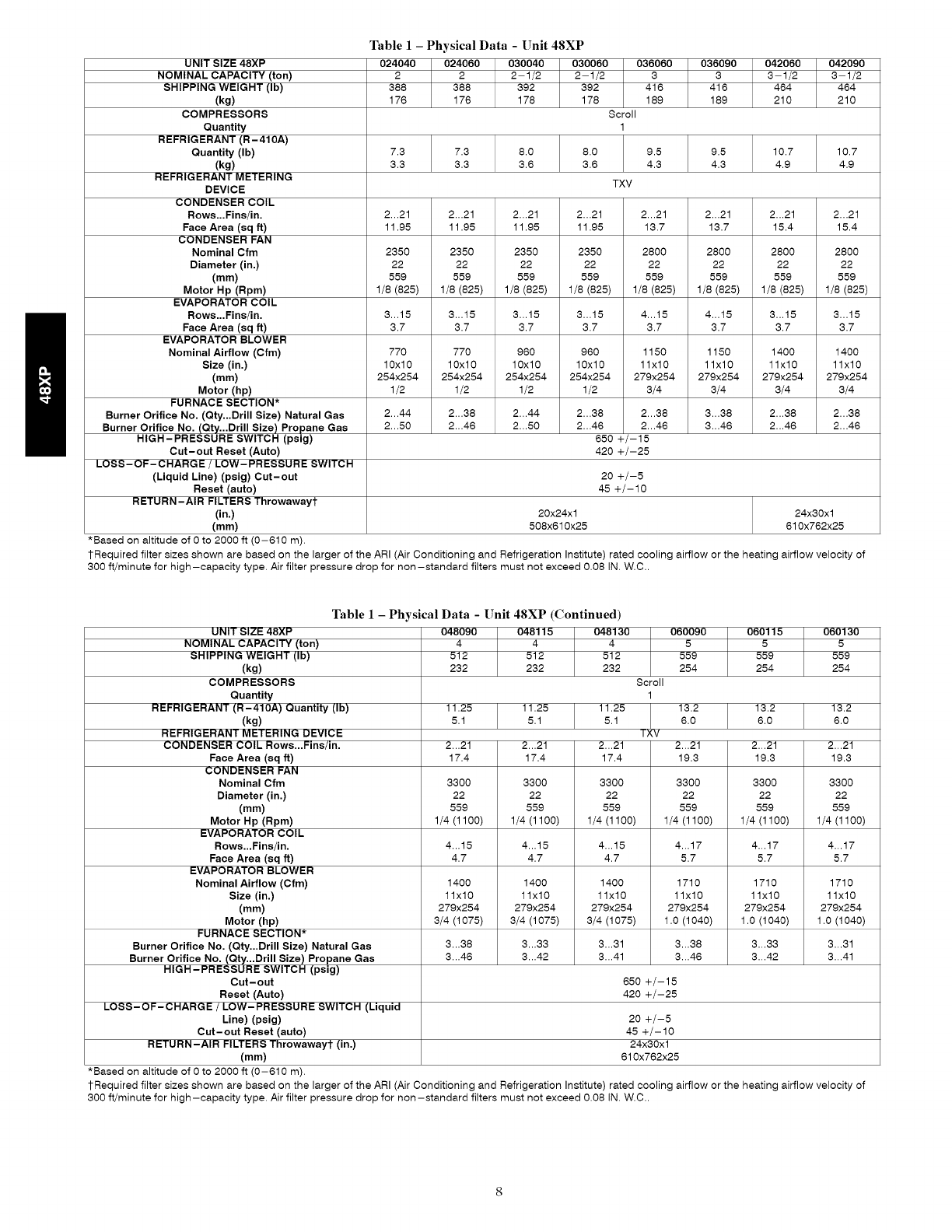
Table 1 - Physical Data -Unit 48XP
024040 024060 030040 030080 036080
2 2 2-1/2 2-1/2 3
388 388 392 392 416
176 176 178 178 189
Scroll
1
036090 042060 042090
3 3-1/2 3-1/2
416 464 464
189 210 210
7.3 7.3 8.0 8.0 9.5 9.5 10.7 10.7
3.3 3.3 3.6 3.6 4.3 4.3 4.9. 4.9
TXV
2...21 2...21 2...21 2...21 2...21 2...21 2...21 2...21
11.95 11.95 11.95 11.95 13.7 13.7 15.4 15.4
2350 2350 2350 2350 2800 2800 2800 2800
22 22 22 22 22 22 22 22
559 559 559 559 559 559 559 559
1/8 (825) 1/8 (825) 1/8 (825) 1/8 (825) 1/8 (825) 1/8 (825) 1/8 (825) 1/8 (825)
3...15 3...15 3...15 3...15 4...15 4...15 3...15 3...15
3.7 3.7 3.7 3.7 3.7 3.7 3.7 3.7
770 770 960 960 1150 1150 1400 1400
10x10 10x10 10x10 10x10 1lx10 1lx10 1lx10 1lx10
254x254 254x254 254x254 254x254 279x254 279x254 279x254 279x254
1/2 1/2 1/2 1/2 3/4 3/4 3/4 3/4
2...44 2...38 2...44 2...38 2...38 3...38 2...38 2...38
2...50 2...46 2...50 2...46 2...46 3...46 2...46 2...46
650 +/-15
420 +/-25
20 +/-5
45 +/-10
20x24x1 24x30x1
508x610x25 610x762x25
1-Required filter sizes shown are based on the larger of the ARI (Air Conditioning and Refrigeration Institute) rated cooling airflow or the heating airflow velocity of
300 ft/minute for high-capacity type. Air filter pressure drop for non-standard filters must not exceed 0.08 IN. W.C..
Table 1 -Physical Data -Unit 48XP (Continued)
UNIT SIZE 48XP 048090 048115 048130 060090 060115 060130
NOMINAL CAPACITY (ton) 4 4 4 5 5 5
SHIPPING WEIGHT (Ib) 512 512 512 559 559 559
(kg) 232 232 232 254 254 254
COMPRESSORS Scroll
Quantity 1
REFRIGERANT (R-410A) Quantity (Ib) 11.25 11.25 11.25 13.2 13.2 13.2
(kg) 5.1 5.1 5.1 6.0 6.0 6.0
REFRIGERANT METERING DEVICE T; IV
CONDENSER COIL Rows...Fins/in. 2...21 2...21 2...21 2...21 2...21 2...21
Face Area (sq ft) 17.4 17.4 17.4 19.3 19.3 19.3
CONDENSER FAN
Nominal Cfm 3300 3300 3300 3300 3300 3300
Diameter (in.) 22 22 22 22 22 22
(mm) 559 559 559 559 559 559
Motor Hp (Rpm) 1/4 (1100) 1/4 (1100) 1/4 (1100) 1/4 (1100) 1/4 (1100) 1/4 (1100)
EVAPORATOR COIL
Rows...Fins/in. 4...15 4...15 4...15 4...17 4...17 4...17
Face Area (sq ft) 4.7 4.7 4.7 5.7 5.7 5.7
EVAPORATOR BLOWER
Nominal Airflow (Cfm) 1400 1400 1400 1710 1710 1710
Size (in.) 1lx10 1lx10 1lx10 1lx10 1lx10 1lx10
(mm) 279x254 279x254 279x254 279x254 279x254 279x254
Motor (hp) 3/4 (1075) 3/4 (1075) 3/4 (1075) 1.0 (1040) 1.0 (1040) 1.0 (1040)
FURNACE SECTION*
Burner Orifice No. (Qty...Drill Size) Natural Gas 3...38 3...33 3...31 3...38 3...33 3...31
Burner Orifice No. (Qty._Drill Size) Propane Gas 3...46 3...42 3...41 3...46 3...42 3...41
HIGH-PRESSURE SWITCH (psig)
Cut-out 650 +/-15
Reset (Auto) 420 +/-25
LOSS-OF-CHARGE /LOW-PRESSURE SWITCH (Liquid
Line) (psig) 20 +/-5
Cut-out Reset (auto) 45 +/-10
RETURN-AIR FILTERS Throwaway'[" (in.) 24x30x1
(mm) 610x762x25
*Based on altitude of 0 to 2000 ft (0-610 m).
1-Required filter sizes shown are based on the larger of the ARI (Air Conditioning and Refrigeration Institute) rated cooling airflow or the heating airflow velocity of
300 if/minute for high-capacity type. Air filter pressure drop for non-standard filters must not exceed 0.08 IN. W.C..
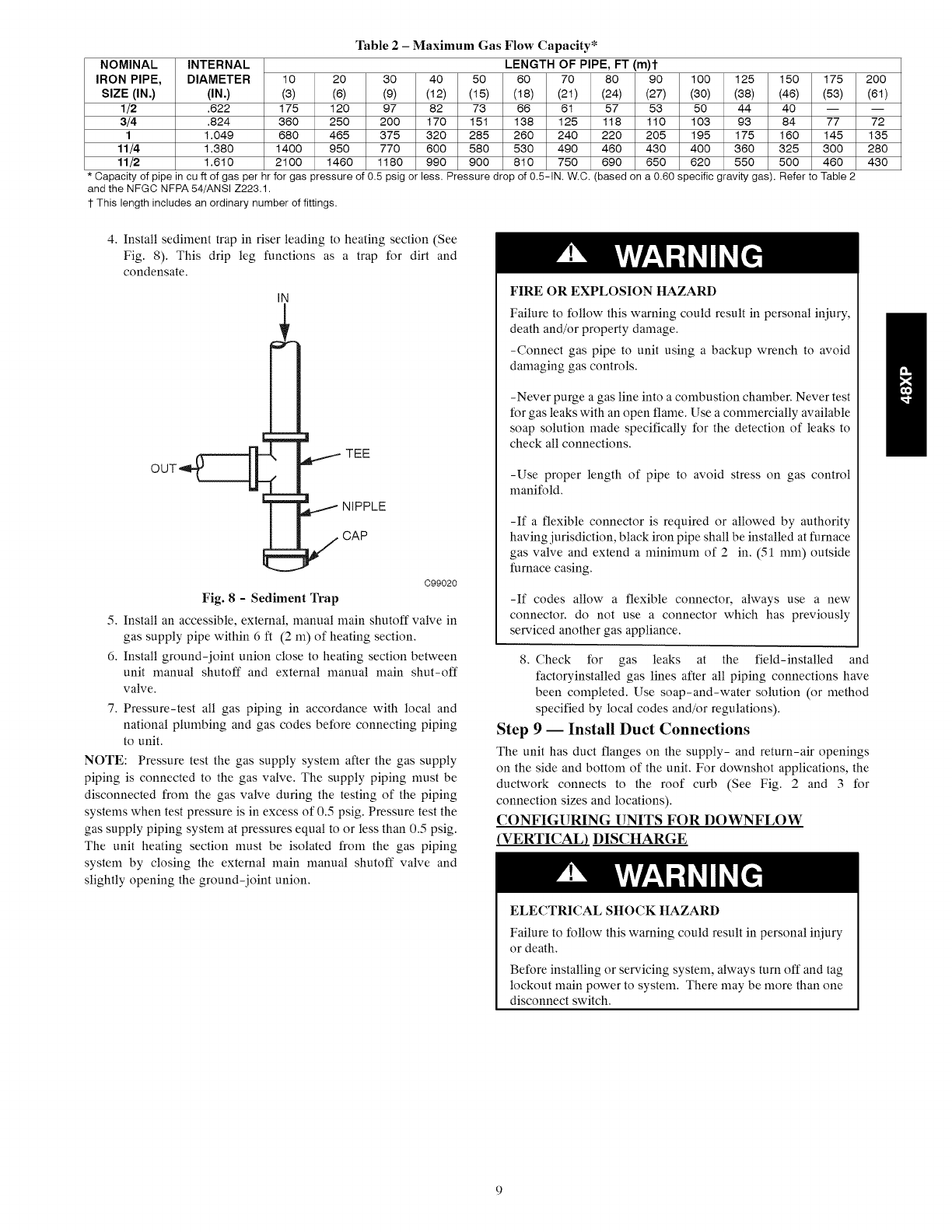
Table2- MaximumGas Flow Capacity*
NOMINAL INTERNAL LENGTH OF PIPE, FT (m)t
IRON PIPE, DIAMETER 10 20 30 40 50 80 70 80 90 100 125 150 175 200
SIZE (IN,) (IN,) (3) (8) (9) (12) (15) (18) (21) (24) (27) (30) (38) (48) (53) (81)
1/2 .822 175 120 97 82 73 88 81 57 53 50 44 40 -- --
3/4 .824 380 250 200 170 151 138 125 118 110 103 93 84 77 72
1 1.049 880 485 375 320 285 280 240 220 205 195 175 180 145 135
11/4 1.380 1400 950 770 800 580 530 490 480 430 400 380 325 300 280
11/2 1.810 2100 1480 1180 990 900 810 750 890 850 820 550 500 480 430
* Capacity of pipe in cuft of gas per hr for gas pressure of 0.5 psig or less. Pressure drop of 0.5-IN. W.C. (based on a 0.60 specific gravity gas). Refer to Table 2
and the NFGC NFPA 54/ANSI Z223.1.
1-This length includes an ordinary number of fittings.
4. Install sediment trap in riser leading to heating section (See
Fig. 8). This drip leg functions as a trap for dirt and
condensate.
IN
TEE
NIPPLE
CAP
C99020
Fig. 8-Sediment Trap
5. Install an accessible, external, manual main shutoff valve in
gas supply pipe within 6 ft (2 m) of heating section.
6. Install ground-joint union close to heating section between
unit manual shutoff and external manual main shut-off
valve.
7. Pressure-test all gas piping in accordance with local and
national plumbing and gas codes before connecting piping
to unit.
NOTE: Pressure test the gas supply system after the gas supply
piping is connected to the gas valve. The supply piping must be
disconnected from the gas valve during the testing of the piping
systems when test pressure is in excess of 0.5 psig. Pressure test the
gas supply piping system at pressures equal to or less than 0.5 psig.
The unit heating section must be isolated from the gas piping
system by closing the external main manual shutoff valve and
slightly opening the ground-joint union.
FIRE OR EXPLOSION HAZARD
Failure to follow this warning could result in personal iniury,
death and/or property damage.
-Connect gas pipe to unit using a backup wrench to avoid
damaging gas controls.
-Never purge a gas line into a combustion chamber. Never test
for gas leaks with an open flame. Use a commercially available
soap solution made specifically for the detection of leaks to
check all connections.
-Use proper length of pipe to avoid stress on gas control
manifold.
-If a flexible connector is required or allowed by authority
having jurisdiction, black iron pipe shall be installed at furnace
gas valve and extend a nfininmm of 2 in. (51 ram) outside
furnace casing.
-If codes allow a flexible connector, always use a new
connector, do not use a connector which has previously
serviced another gas appliance.
8. Check for gas leaks at the field-installed and
factoryinstalled gas lines after all piping connections have
been completed. Use soap-and-water solution (or method
specified by local codes and/or regulations).
Step 9-- Install Duct Connections
The unit has duct flanges on the supply- and return-air openings
on the side and bottom of the unit. For downshot applications, the
ductwork connects to the roof curb (See Fig. 2 and 3 for
connection sizes and locations).
CONFIGURING UNITS FOR DOWNFLOW
_VERTICAL) DISCHARGE
ELECTRICALSHOCK HAZARD
Failure to follow this warning could result in personal iniury
or death.
Before installing or servicing system, always turn off and tag
lockout main power to system, There may be more than one
disconnect switch,
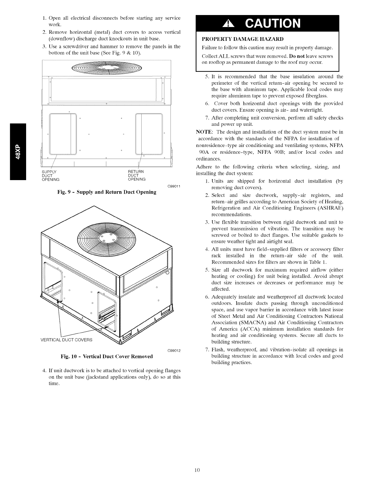
1.Openallelectricaldisconnectsbeforestartinganyservice
work.
2.Removehorizontal(metal)ductcoverstoaccessvertical
(downflow)dischargeductknockoutsinunitbase.
3.Useascrewdriverandhammertoremovethepanelsinthe
bottomoftheunitbase(SeeFig.9& 10).
IIi'
SUPPLY RETURN
DUCT DUCT
OPENING OPENING
Fig. 9 - Supply and Return Duct Opening
C99011
VERTICAL DUCT COVERS
Fig. 10 - Vertical Duct Cover Removed
C99012
4. If unit ductwork is to be attached to vertical opening flanges
on the unit base (jackstand applications only), do so at this
time.
PROPERTY DAMAGE HAZARD
Failure to follow this caution may result in property damage.
Collect ALL screws that were removed. Do not leave screws
on rooftop as permanent damage to the roof may occur.
5. It is recommended that the base insulation around the
perimeter of the vertical return-air opening be secured to
the base with aluminum tape. Applicable local codes may
require aluminum tape to prevent exposed fiberglass.
6. Cover both horizontal duct openings with the provided
duct covers. Ensure opening is air- and watertight.
7. After completing unit conversion, perform all safety checks
and power up unit.
NOTE: The design and installation of the duct system nmst be in
accordance with the standards of the NFPA for installation of
nonresidence-type air conditioning and ventilating systems, NFPA
90A or residence-type, NFPA 90B; and/or local codes and
ordinances.
Adhere to the following criteria when selecting, sizing, and
installing the duct system:
1. Units are shipped for horizontal duct installation (by
removing duct covers).
2. Select and size ductwork, supply-air registers, and
return-air grilles according to American Society of Heating,
Refrigeration and Air Conditioning Engineers (ASHRAE)
recommendations.
3. Use flexible transition between rigid ductwork and unit to
prevent transmission of vibration. The transition may be
screwed or bolted to duct flanges. Use suitable gaskets to
ensure weather tight and airtight seal.
4. All units must have field-supplied filters or accessory filter
rack installed in the return-air side of the unit.
Recommended sizes for filters are shown in Table 1.
5. Size all ductwork for maximum required airflow (either
heating or cooling) for unit being installed. Avoid abrupt
duct size increases or decreases or performance may be
affected.
6. Adequately insulate and weatherproof all ductwork located
outdoors. Insulate ducts passing through unconditioned
space, and use vapor barrier in accordance with latest issue
of Sheet Metal and Air Conditioning Contractors National
Association (SMACNA) and Air Conditioning Contractors
of America (ACCA) n_ininmm installation standards for
heating and air conditioning systems. Secure all ducts to
building structure.
7. Flash, weatherproof, and vibration-isolate all openings in
building structure in accordance with local codes and good
building practices.
10
Step 10 -- Install Electrical Connections
ELECTRICALSHOCK HAZARD
Failure to follow this warning could result in personal injury
or death.
The unit cabinet must have an uninterrupted, unbroken
electrical ground. This ground may consist of an electrical
wire connected to the unit ground screw in the control
compartment, or conduit approved for electrical ground when
installed in accordance with NEC, NFPA 70 National Fire
Protection Association (latest edition) (in Canada, Canadian
Electrical Code CSA C22.1) and local electrical codes.
UNIT COMPONENT DAMAGE HAZARD
Failure to follow this caution could result in damage to the unit
being installed.
1. Make all electrical connections in accordance with NEC
NFPA 70 (latest edition) and local electrical codes
governing such wiring. In Canada, all electrical
connections must be in accordance with CSA standard
C22.1 Canadian Electrical Code Part 1 and applicable
local codes. Refer to unit wiring diagram.
2. Use only copper conductor for connections between
field-supplied electrical disconnect switch and unit. DO
NOT USE ALUMINUM WIRE.
3. Be sure that high-voltage power to unit is within
operating voltage range indicated on unit rating plate. On
3-phase units, ensure phases are balanced within 2
percent. Consult local power company for correction of
improper voltage and/or phase imbalance.
4. Insulate low-voltage wires for highest voltage contained
within conduit when low-voltage control wires are in
same conduit as high-voltage wires.
5. Do not damage internal components when drilling
through any panel to mount electrical hardware, conduit,
etc.
HIGH-VOLTAGE CONNECTIONS
The unit must have a separate electrical service with a
field-supplied, waterproof, disconnect switch mounted at, or
within sight from, the unit. Refer to the unit rating plate for
maximum fuse/circuit breaker size and minimum circuit amps
(ampacity) for wire sizing.
The field-supplied disconnect switch box may be mounted on the
unit over the high-voltage inlet hole when the standard power and
low-voltage entry points are used (See Fig. 2 and 3 for acceptable
location).
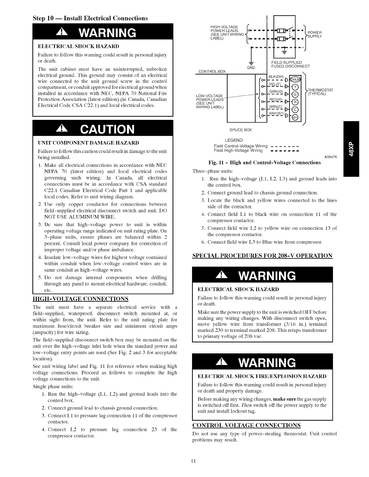
See unit wiring label and Fig. 11 for reference when making high
voltage connections. Proceed as follows to complete the high
voltage connections to the unit.
Single phase units:
1. Run the high-voltage (L1, L2) and ground leads into the
control box.
2. Connect ground lead to chassis ground connection.
3. Connect L1 to pressure lug connection 11 of the compressor
contactor.
4. Connect L2 to pressure lug connection 23 of the
compressor contactor.
LOW-VO LTAG E
POWER LEADS-
(SEE UNIT
WIRING LABEL)
HIGH VOLTAGE r
POWER LEADS I¢_ """
(SEE UNIT WIRING
LABEL) Lc_
mmm
GND
CONTROL BOX
O-
O-
O_
O-
O=
SPLICE BOX
FIELD-SUPPLIED
FUSED DISCONNECT
YZL£Y)--D.i Z-,,'_
GR._(e_)_. i-¢n_
_J
RE DZR2,1>.i-f_
BREC_)_ i"(-€3
,THERMOSTAT
(TYPICAL)
LEGEND
Field Control-Voltage Wiring
Field High-Voltage Wiring .......
A08476
Fig. ll - High and Control-Voltage Connections
Three-phase units:
1. Run the high-voltage (L1, L2, L3) and ground leads into
the control box.
2. Connect ground lead to chassis ground connection.
3. Locate the black and yellow wires connected to the lines
side of the contactor.
4. Connect field LI to black wire on connection 11 of the
compressor contactor.
5. Connect field wire L2 to yellow wire on connection 13 of
the compressor contactor.
6. Connect field wire L3 to Blue wire from compressor.
SPECIAL PROCEDURES FOR 208-V OPERATION
ELECTRICALSHOCK HAZARD
Failure to follow this warning could result in personal injury
or death.
Make sure the power supply to the unit is switched OFF before
making any wiring changes. With disconnect switch open,
move yellow wire from transformer (3/16 in.) terminal
marked 230 to terminal marked 208. This retaps transformer
to primary voltage of 208 vac.
ELECTRICAL SHOCK FIRE/EXPLOSION HAZARD
Failure to follow this warning could result in personal iniury
or death and property damage.
Before making any wiring changes, make sure the gas supply
is switched off first. Then switch off the power supply to the
unit and install lockout tag.
CONTROL VOLTAGE CONNECTIONS
Do not use any type of power-stealing thermostat. Unit control
problems may result.
11
Useno.18AmericanWireGage(AWG)color-coded,insulated
(35Cminimum)wirestomakethecontrolvoltageconnections
betweenthethermostatandtheunit.If thethermostatislocated
morethan100ft (30m)fromtheunit(asmeasuredalongthe
controlvoltagewires),useno.16AWGcolor-coded,insulated(35
Cminimum)wires.
Locatethesixlowvoltagethermostatleadsin24voltsplicebox.
SeeFig.11forconnectiondiagram.Runthelow-voltageleads
fromthethermostat,throughthecontrolwiringinletholegrommet
(Fig.2and3),andintothelow-voltagesplicebox.Provideadrip
loopbeforerunningwiresthroughpanel.Secureandstainreliefall
wiressothattheydonotinterferewithoperationofunit.
Easy Select TM -48XP
EASY SELECT TM CONFIGURATION TAPS FOR 48XP
Easy Select taps are used by the installer to configure a system. The
ECM motor uses the selected taps to modify its operation to a
pre-programmed table of airflows.
The unit must be configured to operate properly with system
components with which it is installed. To successfully configure a
basic system (see information printed on circuit board label located
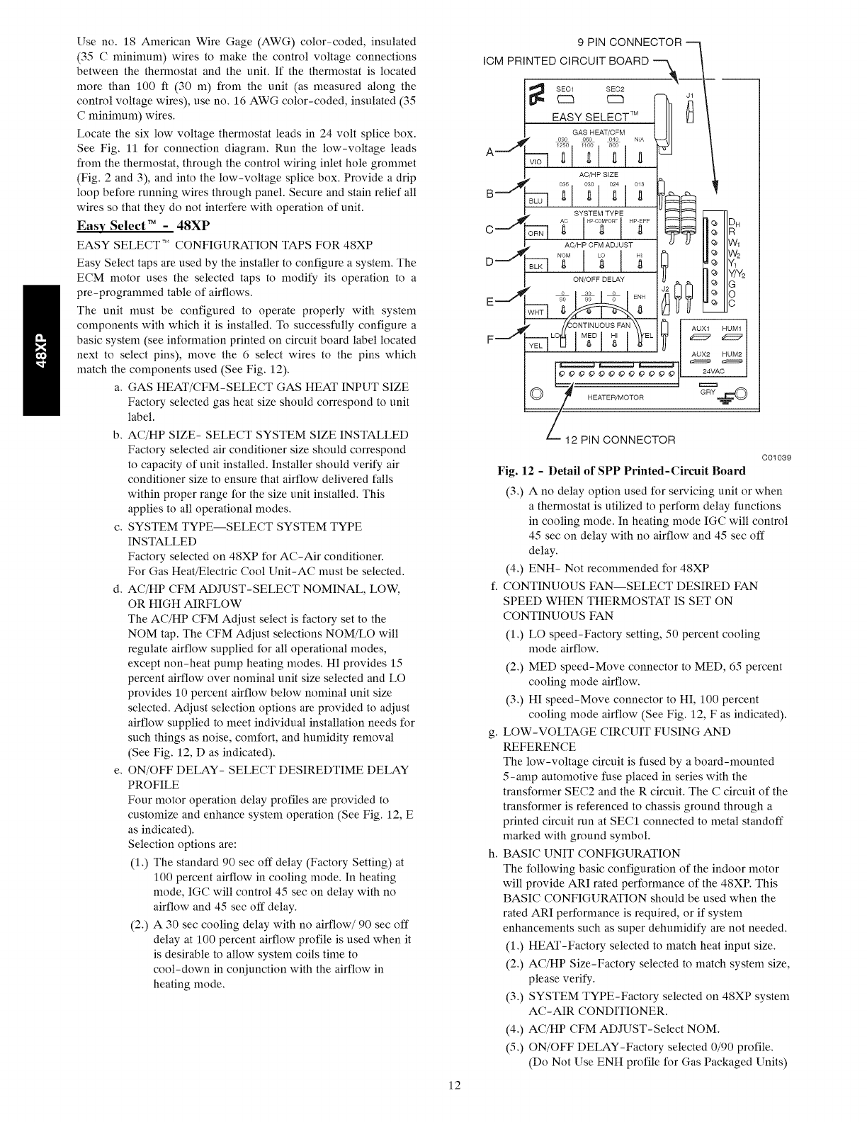
next to select pins), move the 6 select wires to the pins which
match the components used (See Fig. 12).
a. GAS HEAT/CFM-SELECT GAS HEAT INPUT SIZE
Factory selected gas heat size should correspond to unit
label.
b. AC/HP SIZE- SELECT SYSTEM SIZE INSTALLED
Factory selected air conditioner size should correspond
to capacity of unit installed. Installer should verify air
conditioner size to ensure that airflow delivered falls
within proper range for the size unit installed. This
applies to all operational modes.
c. SYSTEM TYPE--SELECT SYSTEM TYPE
INSTALLED
Factory selected on 48XP for AC-Air conditioner.
For Gas Heat/Electric Cool Unit-AC must be selected.
d. AC/HP CFM ADJUST-SELECT NOMINAL, LOW,
OR HIGH AIRFLOW
The AC/HP CFM Adjust select is factory set to the
NOM tap. The CFM Adjust selections NOM/LO will
regulate airflow supplied for all operational modes,
except non-heat pump heating modes. HI provides 15
percent airflow over nominal unit size selected and LO
provides 10 percent airflow below nominal unit size
selected. Adjust selection options are provided to adjust
airflow supplied to meet individual installation needs for
such things as noise, comfort, and humidity removal
(See Fig. 12, D as indicated).
e. ON/OFF DELAY- SELECT DESIREDTIME DELAY
PROFILE
Four motor operation delay profiles are provided to
customize and enhance system operation (See Fig. 12, E
as indicated).
Selection options are:
(1.) The standard 90 sec off delay (Factory Setting) at
100 percent airflow in cooling mode. In heating
mode, IGC will control 45 sec on delay with no
airflow and 45 sec off delay.
(2.) A 30 sec cooling delay with no airflow/90 sec off
delay at 100 percent airflow profile is used when it
is desirable to allow system coils time to
cool-down in conjunction with the airflow in
heating mode.
12
9 PIN CONNECTOR
ICM PRINTED CIRCUIT BOARD '_--_
SEC1
r"m
HEATER/MOTOR
AUX1 HUM1
AUX2 HUM2
24VAC
GRY ==_
12 PIN CONNECTOR
C01039
Fig. 12 - Detail of SPP Printed-Circuit Board
(3.) A no delay option used for servicing unit or when
a thermostat is utilized to perform delay functions
in cooling mode. In heating mode IGC will control
45 sec on delay with no airflow and 45 sec off
delay.
(4.) ENH- Not recommended for 48XP
f. CONTINUOUS FAN--SELECT DESIRED FAN
SPEED WHEN THERMOSTAT IS SET ON
CONTINUOUS FAN
(1.) LO speed-Factory setting, 50 percent cooling
mode airflow.
(2.) MED speed-Move connector to MED, 65 percent
cooling mode airflow.
(3.) HI speed-Move connector to HI, 100 percent
cooling mode airflow (See Fig. 12, F as indicated).
g. LOW-VOLTAGE CIRCUIT FUSING AND
REFERENCE
The low-voltage circuit is fused by a board-mounted
5-amp automotive fuse placed in series with the
transformer SEC2 and the R circuit. The C circuit of the
transformer is referenced to chassis ground through a
printed circuit run at SEC1 connected to metal standoff
marked with ground symbol.
h. BASIC UNIT CONFIGURATION
The following basic configuration of the indoor motor
will provide ARI rated performance of the 48XP. This
BASIC CONFIGURATION should be used when the
rated ARI performance is required, or if system
enhancements such as super dehumidify are not needed.
(1.) HEAT-Factory selected to match heat input size.
(2.) AC/HP Size-Factory selected to match system size,
please verify.
(3.) SYSTEM TYPE-Factory selected on 48XP system
AC-AIR CONDITIONER.
(4.) AC/HP CFM ADJUST-Select NOM.
(5.) ON/OFF DELAY-Factory selected 0/90 profile.
(Do Not Use ENH profile for Gas Packaged Units)
(6.) CONTINUOUS FAN-Select desired fan speed
when thermostat is set to continuous fan.
i. COMFORT OPTIONS--SUPER DEHUMIDIFY (See
Quick Reference Guide)
The Super Dehumidify option is possible when this unit
is installed with a field supplied Thermidistat _ control
(SuperDehumidify does not require an outdoor
temperature sensor). The following configuration is
recommended for n_axinmm cooling/dehumidifying
comfort. This configuration will improve the comfort
provided by the air conditioning system if more
humidity removal is desired. While providing this
improved comfort, the system will operate efficiently,
but not at the published ARI SEER efficiency. During
cool-to-dehumidify call, it provides maximum
dehumidification by reducing airflow to a n_ininmm.
The actual super dehumidify command from
Thermidistat control to the indoor unit is a :'Y" signal
without a :'G" signal in addition to dehumidify signal.
The indoor unit responds to this combination by
reducing the airflow to a n_ininmm. All other
characteristics of cool to dehumidify are the same. The
following system configuration is recommended for
n_axinmm cooling/dehumidifying comfort (See Fig. 12).
(1.) HEAT-Factory selected to match gas heat size of
unit installed.
(2.) AC/HP Size-Factory selected to match system size,
please verify.
(3.) SYSTEM TYPE-Factory selected on 48XP system
AC-AIR CONDITIONER.
(4.) AC/HP CFM ADJUST-Select NOM.
(5.) ON/OFF DELAY-Select :'0/0" profile.
(6.) CONTINUOUS FAN-Select desired fan speed
when thermostat is set to continuous fan.
(7.) DEHUMIDIFY MODE-Remove J1 jumper to
activate.
NOTE: J1 jumper should only be removed when a Thermidistat,
humidistat or capable zoning control is installed.
(8.) LOW VOLTAGE CONNECTIONS-Make
connections as shown in ELECTRICAL
CONNECTIONS section.
(9.) CONFIGURE THERMIDISTAT-Follow
Thermidistat (or capable zoning system)
installation instructions for Super Dehumidify
operation.
ACCESSORY INSTALLATION
a. AUXILIARY TERMINALS The AUX and HUM
terminals on the Easy Select Board are tied directly to
the G terminal, and provide a 24-v. signal whenever the
G terminal is energized (See Fig. 12). During Super
dehumidify mode, the G signal is not present and the
auxiliary terminals are not energized. If the installation
includes the use of this operating mode, do not use these
terminals to control accessories. See Electronic Air
Cleaner and Humidifier sections for further information.
b. ELECTRONIC AIR CLEANER CONNECTIONS
The AUXI and AUX2 terminals are not always
energized during blower operations, as described above.
When using an electronic air cleaner with the unit, use
Airflow Sensor (See Air Cleaner Price Pages for Part
Number). The airflow sensor turns on electronic air
cleaner when the blower is operating.
HUM 1FI
(c)
HUM 2[7
(G)
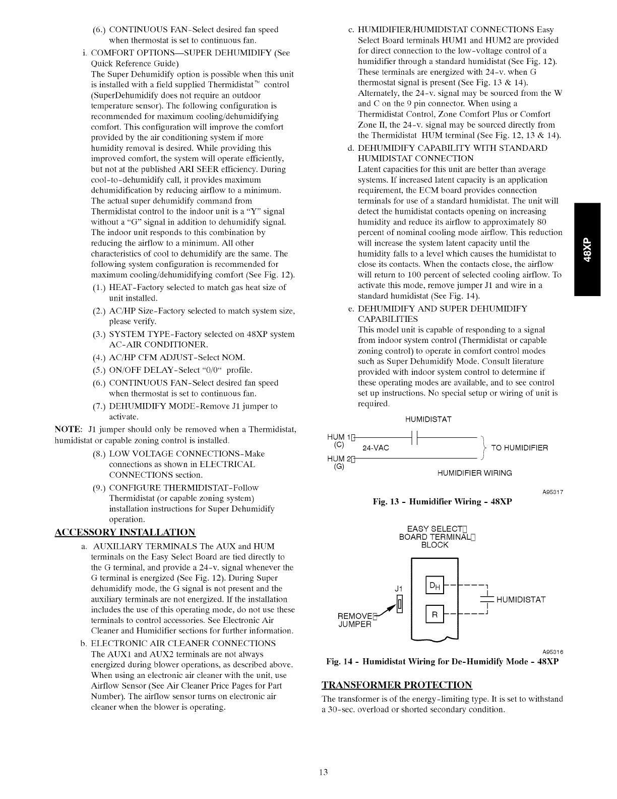
c. HUMIDIFIER/HUMIDISTAT CONNECTIONS Easy
Select Board terminals HUM1 and HUM2 are provided
for direct connection to the low-voltage control of a
humidifier through a standard humidistat (See Fig. 12).
These terminals are energized with 24-v. when G
thermostat signal is present (See Fig. 13 & 14).
Alternately, the 24-v. signal may be sourced from the W
and C on the 9 pin connector. When using a
Thermidistat Control, Zone Comfort Plus or Comfort
Zone II, the 24-v. signal may be sourced directly from
the Thermidistat HUM terminal (See Fig. 12, 13 & 14).
d. DEHUMIDIFY CAPABILITY WITH STANDARD
HUMIDISTAT CONNECTION
Latent capacities for this unit are better than average
systems. If increased latent capacity is an application
requirement, the ECM board provides connection
terminals for use of a standard humidistat. The unit will
detect the humidistat contacts opening on increasing
humidity and reduce its airflow to approximately 80
percent of nominal cooling mode airflow. This reduction
will increase the system latent capacity until the
humidity falls to a level which causes the humidistat to
close its contacts. When the contacts close, the airflow
will return to 100 percent of selected cooling airflow. To
activate this mode, remove jumper J1 and wire in a
standard humidistat (See Fig. 14).
e. DEHUMIDIFY AND SUPER DEHUMIDIFY
CAPABILITIES
This model unit is capable of responding to a signal
from indoor system control (Thermidistat or capable
zoning control) to operate in comfort control modes
such as Super Dehumidify Mode. Consult literature
provided with indoor system control to determine if
these operating modes are available, and to see control
set up instructions. No special setup or wiring of unit is
required.
HUMIDISTAT
24-VAC _ TO HUMIDIFIER
J
HUMIDIFIER WIRING
Fig. 13 -Humidifier Wiring -48XP
A95317
EASY SELECTIq
BOARD TERMINALF]
BLOCK
J1
REMovEJ
JUMPER
1
IHUMIDISTAT
I
l
A95316
Fig. 14 -Humidistat Wiring for De-Humidify Mode -48XP
TRANSFORMER PROTECTION
The transformer is of the energy-limiting type. It is set to withstand
a 30-sec. overload or shorted secondary condition.
13

PRE-START-UP
FIRE, EXPLOSION, ELECTRICAL SHOCK HAZARD
Failure to follow this warning could result in personal injury,
death or property damage.
1. Follow recognized safety practices and wear protective
goggles when checking or servicing refrigerant system.
2. Do not operate compressor or provide any electric power
to unit unless compressor terminal cover is in place and
secured.
3. Do not remove compressor terminal cover until all
electrical sources are disconnected and tagged.
4. Relieve and recover all refrigerant from system before
touching or disturbing anything inside terminal box if
refrigerant leak is suspected around compressor
terminals.
5. Never attempt to repair soldered connection while
refrigerant system is under pressure.
6. Do not use torch to remove any component. System
contains oil and refrigerant under pressure.
To remove a component, wear protective goggles and
proceed as follows:
a. Shut off electrical power to unit and install lockout
tag.
b. Relieve and reclaim all refrigerant from system
using both high- and low-pressure ports.
c. Cut component connecting tubing with tubing
cutter and remove component from unit.
d. Carefully unsweat remaining tubing stubs when
necessary. Oil can ignite when exposed to torch
flame.
Proceed as follows to inspect and prepare the unit for initial startu _:
1. Remove access panel.
2. Read and follow instructions on all WARNING,
CAUTION, and INFORMATION labels attached to, or
shipped with, unit.
3. Make the following inspections:
a. Inspect for shipping and handling damages such as
broken lines, loose parts, disconnected wires, etc.
b. Inspect for oil at all refrigerant tubing connections and
on unit base. Detecting oil generally indicates a
refrigerant leak.
c. Leak test all refrigerant tubing connections using
electronic leak detector, halide torch, or liquid-soap
solution. If a refrigerant leak is detected, see the Check
for Refrigerant Leaks section.
d. Inspect all field- and factory-wiring connections. Be
sure that connections are completed and tight.
e. Inspect coil fins. If damaged during shipping and
handling, carefully straighten fins with a fin comb.
4. Verify the following conditions:
FIRE, EXPLOSION HAZARD
Failure to follow this warning could result in personal injury,
death or property damage.
Do not purge gas supply into the combustion chamber. Never
test for gas leaks with an open flame. Use a commercially
available soap solution made specifically for the detection of
leaks to check all connections.
a. Make sure gas line is free of air. Before lighting the unit
for the first time, perform the following with the gas
valve in the "OFF" position:
If the gas supply pipe was not purged before connecting
the unit, it will be full of air. It is recommended that the
ground joint union be loosened, and the supply line be
allowed to purge until the odor of gas is detected. Never
purge gas lines into a combustion chamber. Immediately
upon detection of gas odor, retighten the union. Allow 5
minutes to elapse, then light unit.
b. Make sure that condenser-fan blade is correctly
positioned in fan orifice. Leading edge of condenser-fan
blade should be 1/2 in. (13 mm) maximum from fan
orifice.
c. Ensure fan hub is 1/8 in. (3 mm) maximum from motor
housing (See Fig. 15).
d. Make sure that air filter(s) is in place.
e. Make sure that condensate drain trap is filled with water
to ensure proper drainage.
f. Make sure that all tools and miscellaneous loose parts
have been removed.
1/8" (3 mm) MAX BETWEEN MOTOR SHAFT
MOTORAND FAN HUB
A08474
Fig. 15 -Fan Blade Clearance
START-UP
Step 1-- Check for Refrigerant Leaks
Proceed as follows to locate and repair a refrigerant leak and to
charge the unit:
1. Locate leak and make sure that refrigerant system pressure
has been relieved and reclaimed from both high- and
low-pressure ports.
2. Repair leak following Refrigerant Service procedures.
NOTE: Install a filter drier whenever the system has been opened
for repair.
3. Add a small charge of R-410A refrigerant vapor to system
and leak-test unit.
4. Evacuate and recover refrigerant from refrigerant system if
additional leaks are not found.
5. Charge unit with R-410A refrigerant, using a volume tric-
charging cylinder or accurate scale. Refer to unit rating plate
for required charge.
Step 2 -- Unit Sequence of Operation
48XP Sequence of Operation
a. CONTINUOUS FAN
(1.) Thermostat closes circuit R to G-The Blower runs
at continuous fan airfow.
b. COOLING MODE
(1.) If indoor temperature is above temperature set
point and humidity is below humidity set point,
thermostat closes circuits R to G, R to Y/Y2 and R
to O-The unit delivers single speed cooling
airflow.
c. COOLING MODE-DEHUMIDIFICATION
(1.) If indoor temperature is above temperature set
point and humidity is above humidity set point,
14
thermostat or Thermidistat closes circuits Rto G, R
to Y/Y2, R to O and humidistat or Thermidistat
opens R to DH-The unit delivers airflow which is
approximately 80 percent of the nominal cooling
airflow to increase the latent capacity of the system.
d. COOLING MODE-SUPER DEHUMIDIFY
OPERATION (SEE QUICK REFERENCE GUIDE)
NOTE: The indoor control used, such as a Thermidistat, must be
capable of providing Super Dehumidify operation mode and
control must be configured as outlined in its installation
instructions. Consult indoor control literature to determine if
control is capable of providing Super Dehumidify inputs and for
configuration instruction.
(1.) If the indoor temperature is below the temperature
set point and the humidity is above the humidity
set point, the Thermidistat closes circuit R to O,
opens circuits R to DH and R to G, and closes
circuit R to Y/Y2. If circuit R to G is closed
(24-v.), the motor will deliver airflow at the full
cooling or cooling plus dehumidify mode
requested value. If circuit R to G is open (0-v.) for
Super Dehumidify mode, the motor delivers
reduced airflow to maximize the humidity removal
of the system while minimizing over cooling.
e. GAS HEATING MODE
(1.) Thermostat closes circuit R to W/WI-The unit
delivers the selected gas heat airflow. The IGC will
control a 45 sec. blower "On" delay and a 45 sec.
"Off"' delay.
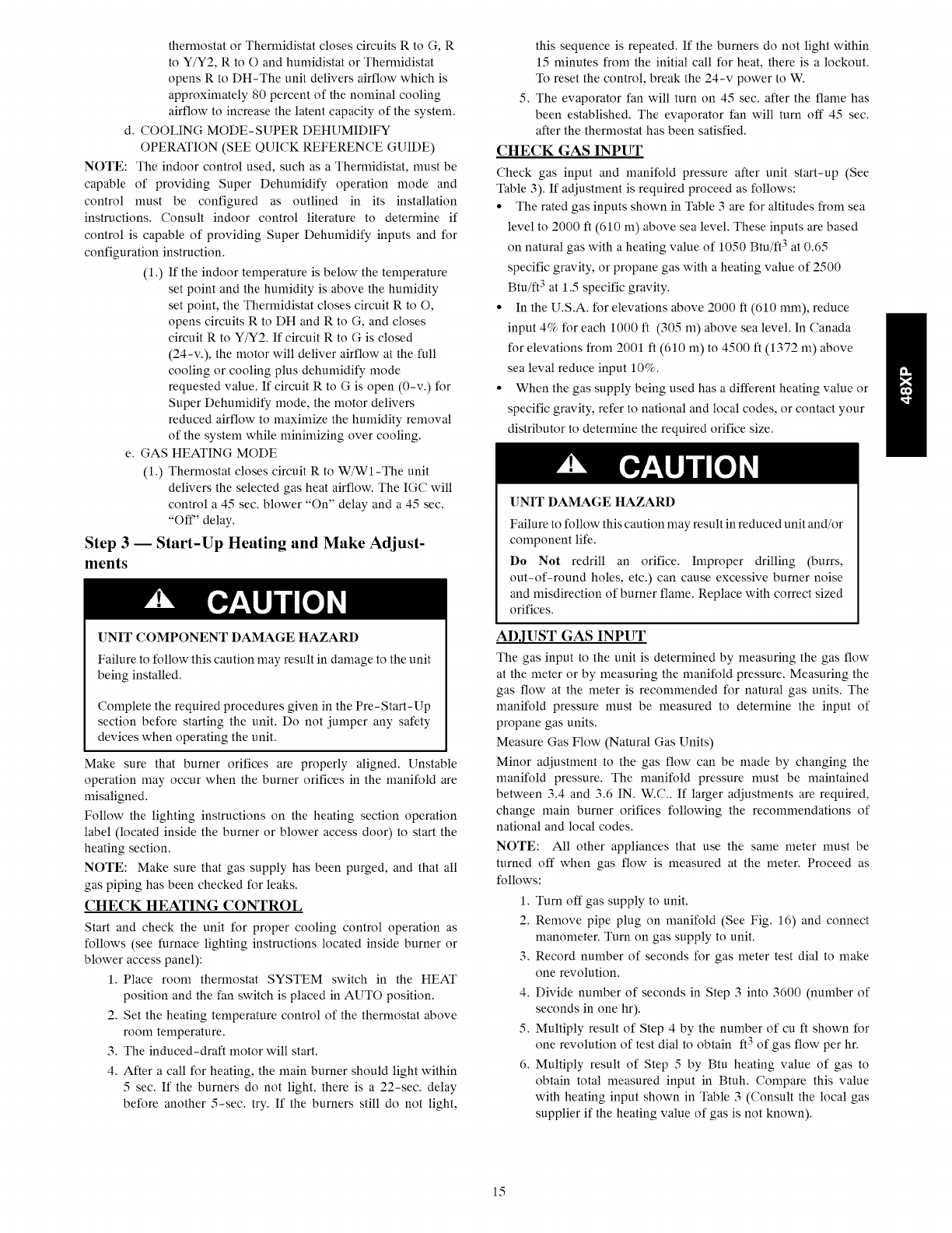
Step 3 -- Start-Up Heating and Make Adjust-
ments
UNIT COMPONENT DAMAGE HAZARD
Failure to follow this caution may result in damage to the unit
being installed.
Complete the required procedures given in the Pre-Start-Up
section before starting the unit. Do not jumper any safety
devices when operating the unit.
Make sure that burner orifices are properly aligned. Unstable
operation may occur when the burner orifices in the manifold are
misaligned.
Follow the lighting instructions on the heating section operation
label (located inside the burner or blower access door) to start the
heating section.
NOTE: Make sure that gas supply has been purged, and that all
gas piping has been checked for leaks.
CHECK HEATING CONTROL
Start and check the unit for proper cooling control operation as
follows (see furnace lighting instructions located inside burner or
blower access panel):
1. Place room thermostat SYSTEM switch in the HEAT
position and the fan switch is placed in AUTO position.
2. Set the heating temperature control of the thermostat above
room temperature.
3. The induced-draft motor will start.
4. After a call for heating, the main burner should light within
5 sec. If the burners do not light, there is a 22-sec. delay
before another 5-sec. try. If the burners still do not light,
this sequence is repeated. If the burners do not light within
15 minutes from the initial call for heat, there is a lockout.
To reset the control, break the 24-v power to W.
5. The evaporator fan will turn on 45 sec. after the flame has
been established. The evaporator fan will turn off 45 sec.
after the thermostat has been satisfied.
CHECK GAS INPUT
Check gas input and manifold pressure after unit start-up (See
Table 3). If adjustment is required proceed as follows:
• The rated gas inputs shown in Table 3 are for altitudes from sea
level to 2000 ft (610 m) above sea level. These inputs are based
on natural gas with a heating value of 1050 Btu/ft 3 at 0.65
specific gravity, or propane gas with a heating value of 2500
Btu/ft 3 at 1.5 specific gravity.
• In the U.S.A. for elevations above 2000 ft (610 mm), reduce
input 4% for each 1000 ft (305 m) above sea level. In Canada
for elevations from 2001 ft (610 m) to 4500 ft (1372 m) above
sea leval reduce input 10%.
• When the gas supply being used has a different heating value or
specific gravity, refer to national and local codes, or contact your
distributor to determine the required orifice size.
UNIT DAMAGE HAZARD
Failure to follow this caution may result in reduced unit and/or
component life.
Do Not redrill an orifice. Improper drilling (burrs,
out-of-round holes, etc.) can cause excessive burner noise
and misdirection of burner flame. Replace with correct sized
orifices.
ADJUST GAS INPUT
The gas input to the unit is determined by measuring the gas flow
at the meter or by measuring the manifold pressure. Measuring the
gas flow at the meter is recommended for natural gas units. The
manifold pressure must be measured to determine the input of
propane gas units.
Measure Gas Flow (Natural Gas Units)
Minor adjustment to the gas flow can be made by changing the
manifold pressure. The manifold pressure must be maintained
between 3.4 and 3.6 IN. W.C.. If larger adjustments are required,
change main burner orifices following the recommendations of
national and local codes.
NOTE: All other appliances that use the same meter must be
turned off when gas flow is measured at the meter. Proceed as
follows:
1. Turn off gas supply to unit.
2. Remove pipe plug on manifold (See Fig. 16) and connect
manometer. Turn on gas supply to unit.
3. Record number of seconds for gas meter test dial to make
one revolution.
4. Divide number of seconds in Step 3 into 3600 (number of
seconds in one hr).
5. Multiply result of Step 4 by the number of cuft shown for
one revolution of test dial to obtain ft 3 of gas flow per hr.
6. Multiply result of Step 5 by Btu heating value of gas to
obtain total measured input in Btuh. Compare this value
with heating input shown in Table 3 (Consult the local gas
supplier if the heating value of gas is not known).
15
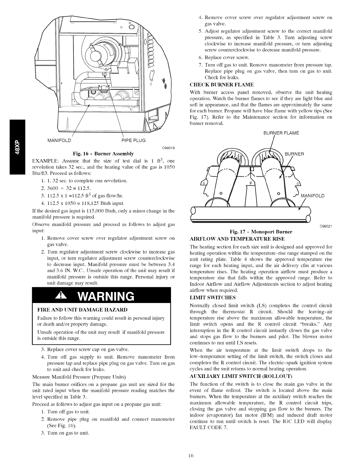
MANIFOLD PIPE PLUG
C99019
Fig. 16 -Burner Assembly
EXAMPLE: Assume that the size of test dial is 1 ft3, one
revolution takes 32 sec., and the heating value of the gas is 1050
Btu/ft3. Proceed as follows:
1. 1.32 sec. to complete one revolution.
2. 3600 + 32 = 112.5.
3. 112.5 x 1 =112.5 ft3 of gas flow/hr.
4. 112.5 x 1050 = 118,125 Btuh input.
If the desired gas input is 115,000 Btuh, only a minor change in the
manifold pressure is required.
Observe manifold pressure and proceed as follows to adjust gas
input:
1. Remove cover screw over regulator adjustment screw on
gas valve.
2. Turn regulator adjustment screw clockwise to increase gas
input, or turn regulator adjustment screw counterclockwise
to decrease input. Manifold pressure nmst be between 3.4
and 3.6 IN. W.C.. Unsafe operation of the unit may result if
manifold pressure is outside this range. Personal injury or
unit damage may result.
FIRE AND UNIT DAMAGE HAZARD
Failure to follow this warning could result in personal iniury
or death and/or property damage.
Unsafe operation of the unit may result if manifold pressure
is outside this range.
3. Replace cover screw cap on gas valve.
4. Turn off gas supply to unit. Remove manometer from
pressure tap and replace pipe plug on gas valve. Turn on gas
to unit and check for leaks.
Measure Manifold Pressure (Propane Units)
The main burner orifices on a propane gas unit are sized for the
unit rated input when the manifold pressure reading matches the
level specified in Table 3.
Proceed as follows to adjust gas input on a propane gas unit:
1. Turn off gas to unit.
2. Remove pipe plug on manifold and connect manometer
(See Fig. 16).
3. Turn on gas to unit.
4. Remove cover screw over regulator adjustment screw on
gas valve.
5. Adjust regulator adjustment screw to the correct manifold
pressure, as specified in Table 3. Turn adjusting screw
clockwise to increase manifold pressure, or turn adjusting
screw counterclockwise to decrease manifold pressure.
6. Replace cover screw.
7. Turn off gas to unit. Remove manometer from pressure tap.
Replace pipe plug on gas valve, then turn on gas to unit.
Check for leaks.
CHECK BURNER FLAME
With burner access panel removed, observe the unit heating
operation. Watch the burner flames to see if they are light blue and
soft in appearance, and that the flames are approximately the same
for each burner. Propane will have blue flame with yellow tips (See
Fig. 17). Refer to the Maintenance section for information on
burner removal.
BURNER FLAME
BURNER
MAN IFOLD
C99021
Fig. 17 -Monoport Burner
AIRFLOW AND TEMPERATURE RISE
The heating section for each size unit is designed and approved for
heating operation within the temperature-rise range stamped on the
unit rating plate. Table 4 shows the approved temperature rise
range for each heating input, and the air delivery cfm at various
temperature rises. The heating operation airflow must produce a
temperature rise that falls within the approved range. Refer to
Indoor Airflow and Airflow Adjustments section to adjust heating
airflow when required.
LIMIT SWITCHES
Normally closed limit switch (LS) completes the control circuit
through the thermostat R circuit. Should the leaving-air
temperature rise above the naaxinmm allowable temperature, the
limit switch opens and the R control circuit "breaks." Any
interruption in the R control circuit instantly closes the gas valve
and stops gas flow to the burners and pilot. The blower motor
continues to run until LS resets.
When the air temperature at the limit switch drops to the
low-temperature setting of the limit switch, the switch closes and
completes the R control circuit. The electric-spark ignition system
cycles and the unit returns to normal heating operation.
AUXILIARY LIMIT SWITCH (ROLLOUT)
The function of the switch is to close the main gas valve in the
event of flame rollout. The switch is located above the main
burners. When the temperature at the auxiliary switch reaches the
maximum allowable temperature, the R control circuit trips,
closing the gas valve and stopping gas flow to the burners. The
indoor (evaporator) fan motor (IFM) and induced draft motor
continue to run until switch is reset. The IGC LED will display
FAULT CODE 7.
16
Step 4 -- Start-Up Cooling and Make Adjust-
ments
UNIT DAMAGE HAZARD
Failure to follow this warning could result in unit component
damage.
Complete the required procedures given in the Pro-Start-Up
section before starting the unit. Do not jumper any safety
devices when operating the unit. Do not operate the
compressor when the outdoor temperature is below 55°F
(13°C) (unless accessory low-ambient kit is installed). Do
not rapid-cycle the compressor. To prevent compressor
damage allow 5 minutes between "on" cycles.
CHECKING COOLING CONTROL OPERATION
Start and check the unit for proper cooling control operation as
follows:
1. Place room thermostat SYSTEM switch in OFF position.
Observe that blower motor starts when FAN switch is
placed in ON position and shuts down when FAN switch is
placed in AUTO. position.
2. Place SYSTEM switch in COOL position and FAN switch
in AUTO. position. Set cooling control below room
temperature. Observe that compressor, condenser fan, and
evaporator blower motors start. Observe that cooling cycle
shuts down when control setting is satisfied. The evaporator
fan will continue to run for the time selected on the Easy
Select board.
3. When using an auto-changeover room thermostat, place
both SYSTEM and FAN switches in AUTO positions.
Observe that unit operates in Heating mode when
temperature control is set to "call for heating" (above room
temperature) and operates in Cooling mode when
temperature control is set to "call for cooling" (below room
temperature).
HEATING
INPUT (BTUH)*
40,000
60,000
90,000
115,000
130,000
NUMBER OF
ORIFICES
2
2
3
3
3
Min
4.0
4.0
4.0
4.0
4.0
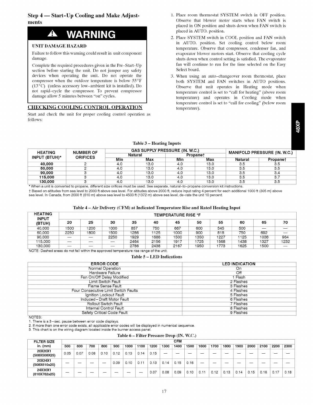
Table 3-Heating Inputs
GAS SUPPLY PHI-SSUHI- (IN. W.C.)
Natural Propanet
Max Min
13.0 4.0
13.0 4.0
13.0 4.0
13.0 4.0
13.0 4.0
Max
13.0
13.0
13.0
13.0
13.0
MANIFOLD PRESSURE (IN. W.C.)
Natural Propanet
3.5 3.5
3.5 3.5
3.5 3.4
3.5 3.7
3.5 3.5
* When a unit is converted to propane, different size orifices must be used. See separate, natural-to-propane conversion kit instructions.
1-Based on altitudes from sea level to 2000 ft above sea level. For altitudes above 2000 ft, reduce input rating 4 percent for each additional 1000 ft (305 m) above
sea level. In Canada, from 2000 ft (610 m) above sea level to 4500 ft (1372 m) above sea level, de-rate the unit 10 percent.
HEATING
INPUT
(BTUH) 20 25 30 35 40 45
40,000 1500 1200 1000 857 750 667
60,000 2250 1800 1500 1285 1125 1000
90,000 -- -- 2250 1929 1688 1500
115,000 -- -- -- 2464 2156 1917
130,000 -- -- -- 2786 2438 2167
NOTE: Dashed areas do not fall within the approved temperature rise range of the unit.
Table 5 - LED Indications
Table 4 -Air Delivery (CFM) at Indicated Temperature Rise and Rated Heating Input
TEMPERATURE RISE °F
50 55 60 65 70
600 545 500 -- --
900 818 750 692 --
1350 1227 1125 1038 964
1725 1568 1438 1327 1232
1950 1773 1625 1500 --
ERROR CODE
Normal Operation
Hardware Failure
Fan On/Off Delay Modified
Limit Switch Fault
Flame Sense Fault
Four Consecutive Limit Switch Faults
Ignition Lockout Fault
Induced- Draft Motor Fault
Rollout Switch Fault
Internal Control Fault
Safety Critical Code Fault
NOTES:
1. There is a 3-sec. pause between error code displays.
2. If more than one error code exists, all applicable error codes will be displayed in numerical sequence.
3. This chart is on the wiring diagram located inside the burner access panel.
Table 6-Filter Pressure Drop (IN. W.C.)
FILTER SIZE CFM
in. (mm) 500 600 700 800 900 1000 1100 1200 1300 1400 1500
20X20X1 0.05 0.07 0.08 0.10 0.12 0.13 0.14 0.15 -- -- --
(508X508X25)
20X24X1 .... 0.09 0.10 0.11 0.13 0.14 0.15 0.16
(508X610x25)
24X30X1 ....... 0.07 0.08 0.09 0.10
(610X762x25)
LED INDICATION
On
Off
1 Flash
2 Flashes
3 Flashes
4 Flashes
5 Flashes
6 Flashes
7 Flashes
8 Flashes
9 Flashes
1600 1700 1800 1900 2000 2100 2200 2300
0.11 0.12 0.13 0.14 0.15 0.16 0.17 0.18
17
UNIT
SIZE
024
030
036
042
048
060
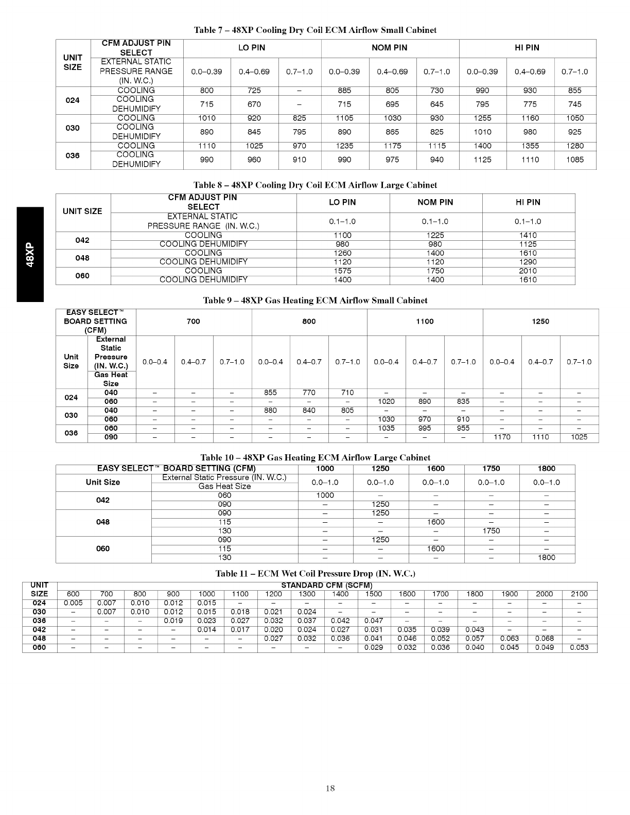
Table 7 - 48XP Cooling Dry Coil ECM Airflow Small Cabinet
CFM ADJUST PIN LO PIN NOM PIN HI PIN
SELECT
UNIT EXTERNAL STATIC
SIZE PRESSURE RANGE 0.0-0.39 0.4-0.69 0.7-1.0 0.0-0.39 0.4-0.69 0.7-1.0 0.0-0.39 0.4-0.69 0.7-1.0
(IN. W.C.)
COOLING 800 725 - 885 805 730 990 930 855
024 COOLING 715 670 - 715 695 645 795 775 745
DEHUMIDIFY
COOLING 1010 920 825 1105 1030 930 1255 1160 1050
030 COOLING 890 845 795 890 865 825 1010 980 925
DEHUMIDIFY
COOLING 1110 1025 970 1235 1175 1115 1400 1355 1280
036 COOLING 990 960 910 990 975 940 1125 1110 1085
DEHUMIDIFY
Table 8 -48XP Cooling Dry (;oil ECM Airflow Large Cabinet
LO PIN NOM PIN HI PIN
UNIT SIZE
0.1-1.0 0.1-1.0 0.1-1.0
042
048
060
CFM ADJUST PIN
SELECT
EXTERNAL STATIC
PRESSURE RANGE (IN. W.C.)
COOLING
COOLING DEHUMIDIFY
COOLING
COOLING DEHUMIDIFY
COOLING
COOLING DEHUMIDIFY
1lO0
98O
1260
1120
1575
1400
1225
98O
1400
1120
1750
1400
EASY SELECT TM
BOARD SETTING
(CFM)
External
Static
Unit Pressure
Size (IN, W,C,)
Gas Heat
Size
040
024 060
040
030 060
060
036 090
1410
1125
1610
1290
2010
1610
Table 9 - 48XP Gas Heating ECM Airflow Small Cabinet
700 800 11oo 1250
0.0-0.4 0.4-0.7 0.7-1.0 0.0-0.4 0.4-0.7 0.7-1.0
855 770 710
880 840 805
0.0-0.4 0.4-0.7 0.7-1.0
1020 890 835
1030 970 910
1035 995 955
0.0-0.4 0.4-0.7 0.7-1.0
1170 1110 1025
600
0.005
External Static Pressure (IN. W.C.)
Gas Heat Size
060
090
090
115
130
090
115
130
0.0-1.0
1600
1600
1750
0.0-1.0
1750
Table 10 - 48XP Gas Heating ECM Airflow Large Cabinet
EASY SELECT TM BOARD SETTING (CFM) 1000 1250 1600
Unit Size 0.0-1.0 0.0-1.0
042 1000 -
- 1250
- 1250
048 - -
- 1250
060 - -
Tablell-ECMWetCoilPressureDrop(IN.W.C.)
STANDARD CFM (SCFM)
18OO
0.0-1.0
1800
700 800 900 1000 1100 1200 1300 1400 1500 1600 1700 1800 1900 2000 2100
0.007 0.010 0.012 0.015 ........
0.007 0.010 0.012 0.015 0.018 0.021 0.024 ......
- - 0.019 0.023 0.027 0.032 0.037 0.042 0.047 .....
- - - 0.014 0.017 0.020 0.024 0.027 0.031 0.035 0.039 0.043 - - -
..... 0.027 0.032 0.036 0.041 0.046 0.052 0.057 0.063 0.068 -
...... 0.029 0.032 0.036 0.040 0.045 0.049 0.053
18
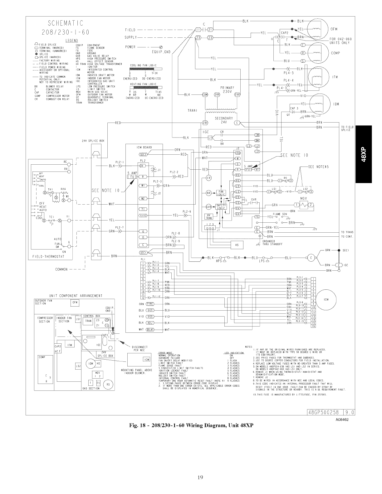
SCII_MAT IC
208/230-_-60
LEGEND
_FIELD SPLICE
O TERM_NAL_MAREED}
o TERMINAL (UNMARNEDI
@ SPLICE
O SPL_CE {MARKED}
FACTORYWIRING
F_ELNCONTROLW_RINO
E_ELD POMERWIRING
ACCESSORYOR OPTIONAL
W_RING
TO _NR_CATECOMMON
POTENTIAL ONLY:
NOTTO REPRESENTMIRING
BR OLOMENREtAY
B CONTACTOR
CAP CAPACITOR
COMB COMPRESSORMOTOR
CR COMBNSTIONRELAY
E_NIP EQUIPMENT
F ELANE SENSOR
FU FUSE
MEN GROUND
GVR GAS VALVE RELAY
NPS NIGH PRESSURESM_TC_
US HALL EFFECTSENSOR
HV TRANHIGH VOLTAGETRANSFORMER
I IBNITON
IBM INTEGRATEDCONTROl
MOTOR
_DM _NDUCEDDRAFT MOTOR
IFM INDOORFAN MOTOR
[MD _NTEGRATEUGAS UNIT
CONTROLLER
kPS LOW PRESSURESM_TDH
LS L_M]T SWlTC_
MGV MAIN GAS VALVE
OFM OUTDOORFAN _OTOR
QT QUADRUPLETERMINAL
RS ROLLOUTSM[TC_
TRAM TRANSEORNER
REg_
_MEAI
°AUTO
ON
F [ ELD TI ERMOSTAT
COMMON
24V SPLICE BOX
BLK@>--
SEE NOTE IO
] _ WHT
z_ YE
PL2 7
GRN_>
I
I
I
I BRN
I
I
UNIT COMPONENT ARRANGEMENT
OUTDOOR FAN
SECT ON
EQUIP
GND k
I
Cs
R
SECTION
:APE _
COMP
GAS SECTION
F_ELD
SUPPLY
POWER
EQU]PGND /
ENERG ZED DE-ENERG ZED
IBM BOARD
PL2
5 AMP
_ ,
PLR"3
<wr> _>-
C_
C_D
CZD
C3[7
PLI
ORN
B[U
v_o
BIN
WET
_DISCONNECT
PER NEC
MOUNTING PANEL ABOVE
INDOOR BLOWER
YEI
TRAN[
..................................BLK
BLN
ORN
PLR-2
;R
PLR-6
YEL_>_
PL28
ORN+_
P[2-9
BRN/_
BRN
GRN
YEL
BLN_
WIlT
PNN
RED
8RN
ORN
GRA
vlo
BLK
WHT
SECONDARY
24V
IGC
@
RED BB Jz CED
GRA _
WHT ........... /
REDI /,_
_B3 _
YEL OFM
_YEL ___Y__ _ _ _ //
_:EL_(_/LU COMP
@
YEL
IFM
_DM
NOTES:
i1[ ANYo_ T1_£ORIGINAL WIRESFURNISDEDARE REPLACED,
_ IT MUSTBE REPLACEDWITR TYPE 9O _EMREED MIREOR
NORNALOPERATIO_ _ ITS EQUIVALENT
_AR_MAREFAIlUrE OF_ 2 SEE _RICE _AGES _OR TI_[RNOSTATANDSUEBASES
FA_ O_/OFF DELAYMODIFIED I _LAS_ SUSE ;5 DEGREECOPPERCORRUPTORSFOR F_ELR E_STALLAfEON
L_M_TS_TC_ _A_tT R RLAS_ES 4 REPLACELOWVOLTAGEFUSES M_TRNOGREATERTHAN5 A_P FUSES¸
FLAMESENSERAULT 3 _tASNES S ON MODE_S4BGPR24 0_ HASLS] _ND LSE _N SER_ES
S CONSECUTIVEtlMIT SWlTC_ _AUtTS 4 _t_S_ES ON_ODELS 48GPO4R 060 _AS LSE O_LY
EGN_EONLOCEOUT_AU_T S ELAS_ES
_NDUCERSWlTD_ _AULT 6 _tAS_ES 6_E_OVE J_ MHENUSING THER_R_STAT/ HU_R_STATANR
ROLLOUTSMITD_ FAULT 7 ELAS_ES DEHR_O_F_CAT_ON_ORE
EN_ERNALCONTROLEAN[T 8 ELASNES _RE_OVE J_
TEMPORARYONE _OU_AUTOMATIC_ESET EANLT_NOTE9} 9 ELASNES B TO 8E W_RER_ ACCORRA_CEMET_ NEC A_DLOCALCODES¸
B SECOND_A_SE BETWEENERRORCODE_ISRtAY _T_S CODE_D_CA_ES A_ [_1ER_AL PROCESSOREA_LT T_ATWILL
2 _F MORET_AN ONE ERROREXISTS, ALL APPLICABLEERRORCODES RESET _TSELF _N ONE_OUR FAUtT CAN6E CENSERBY STRAY_E
S_ALL BE DISRtAYED IN NUMERICAtSEQUENCE S_GNELS _ THE STRUCTUREOR _EARBY TIHS IS A Ut REQUIREMENTEAUtT
[OT_[S FUSE [S MANUFACTUREDB_ LITTEtEUSE, R/N RS_OOS
Fig. 18 - 208/230-1-60 Wiring Diagram, Unit 48XP
A08462
19
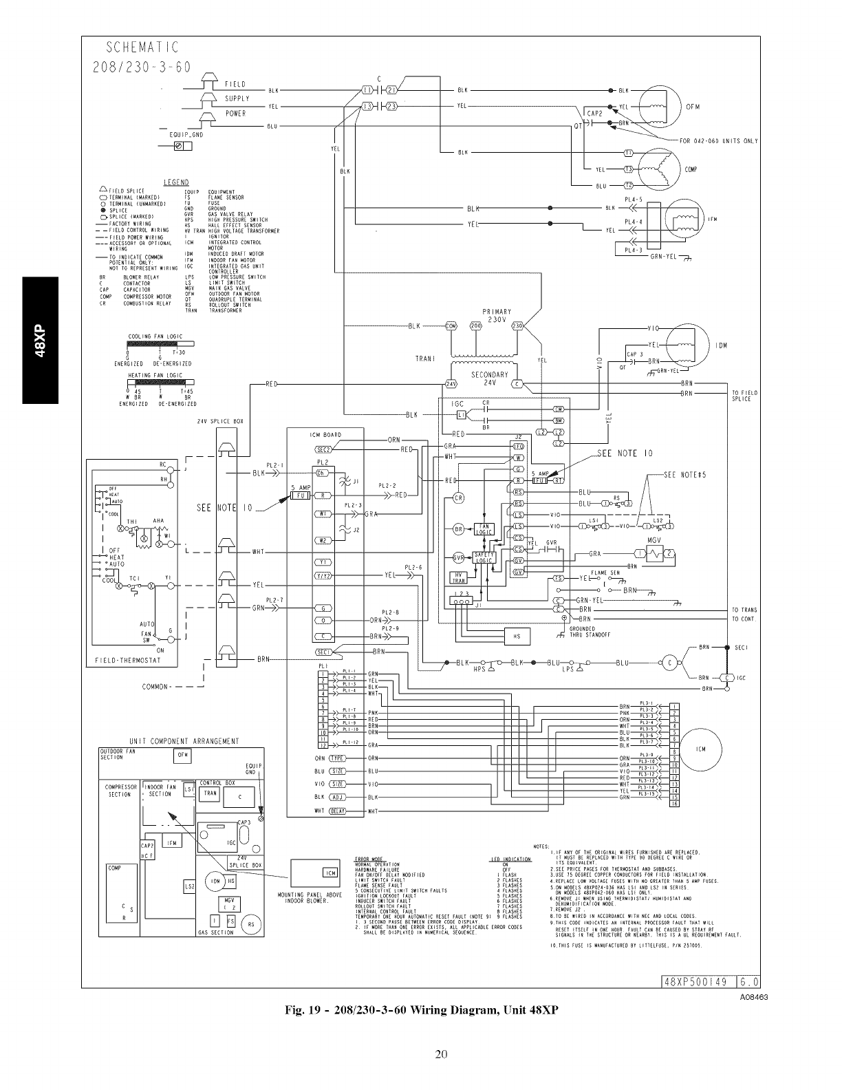
SCHEMATIC
208/230-3-60
FIELD
SUPPLY
__ __]_2_ POWER
EQU tP_GND
BLK
fEL
8LU
LEGEND
_P_ELD SPLICE EQUIP EQUIPMENT
Q TERNINAL {MAR_ED) FS FLAME SENSOR
TERMINAL (UNMARKED) FU FUSE
SPLICE GND GROUND
C],SPLICE (MARKED) GVR GAS VALVE RELAY
HPS HiGH PRESSURE SWITCH
--FACTORY WIRING HS HALL EFFECT SENSOR
-- -- FIELD CONTROL WIRENG HV TRAN H{GH VOLTAGE TRANSFORMER
--- FIELD POWER WIRING E EGNITOR
---- ACCESSORY OR OPTIONAL EC_ ENTEGRATED CONTROL
WIRING _OTOR
IDW iNDUCER DRAFT MOTOR
--TO INDICATE COMMON
POTENTIAL ONLY: tFM ENROOR FAN MOTOR
NOT TO REPRESENT WIRING IGC INTEGRATED GAS UNIT
CONTROLLER
R BLOWER RELAY LPS LOW PRESSURE SWETCH
CONFACTOR LS L{N{T SWITCH
CAP CAPACITOR NOV MAiN GAS VALVE
COMP CONPRESSOR MOTOR OFM OUTDOOR FAN MOTOR
OT QUADRUPLE TERMINAL
ROLLORT SWITCH
CR COMBUSTION RELAY _R_AN IRANSFORmE R
COOLING FAN LOGIC
& _ T130
G
ENERGIZED DE-ENERGIZED
HEATING PAN LOGIC
WBR W BR
ENERGIZED DE-ENERGIZED
OFF
.E_T
IOFF -vv_ _
_HEAT
OAUTO
_COOL TCI Y_
AUTO
ON
FIELD-THERMOSTAT
--RED
COMMON....
24V SPLICE BOX
[------ PL2-1
SEE NOTE lOJ
L-- _--WHT
_--YEL
PL?-T
.... GRN---)>--
I
I
.J
-- _--BRN
I --
I
UNIT COMPONENT ARRANGEMENT
OUTDOOR EAR []
SECTION
EQU
GND
I CONTROL BOX
..... E.... _ND_OOR FAN EII_ [_
SECTION , SECTION
E
c s
Rss£
GAS SECTION
CBLN
YEL
BLH
BLK
YEL
,[/
-BLH
--ORN--
PLB'B RE]
)>-RED
BRA_
PLZ-R
5AMP
PL?-3
C_I>--
C_13---
TRANI
PRIMARY
YEL
SECONDARY
R4V
IGC CR +-
-REDBR JR I _ {_
-WHT
-f+2+-
T
YEL
123 0--
O\Ti__ OFM
OR 042-060 UNITS ONLY
+iL +
++
PL4+4 _FN
--GRN-YEL_
YE I DM
_ I oT meT-GNU" YE L_
II +RN--
_._EE NOTE I0
-SEE NOTE_5
--_L__2_ //
//
MGV
-----SRA _
FLAME SEN
--Y E L---o [
-_o o_ BR_
_RN-YEL H_
--BRN TOTRANS
_--BRN TO CONT
;ROUNDED
IHRU STANDOFF
PLI
E_->_
ORN
BLU
v_o
Wilt
_7_B L KHPs_BL H---_BL U_)_BL U-- _ BRR --
BRN --
BRR--
-GRA
-ORN
-BLU
-VIO
-BLN
-WHT
SECT
>_GC
NOTES:I_F ANy OF THE ORIGINAL WIRES FURNISHED ARE REPLACRD,
_ iT _UST BE REPLACED W_TR TYPE gO DEGREE C _IRE OR
NORMAL OPERA_IO_ ITS EQUIVALENT
RARD_ARE FAILURE OFF Z SEE PRICE PAGES FOR THERMOSTAT AND SUBBASES
FAN ONIOFF DELAY NOD{PiED _ FLASH 3USE 75 DEGREE COPPER CONDUCTORS FOR F_ELD _NSTALLAT_ON
LIMIT SWITCH FAULT ZFLASHES 4REPLACE LOW VOLTAGE FUSES W_TH NO GREATER THAN S A_P FUSES
PLANE SENSE FAULT 3 FLASHES SON _ODZLS 4RXPOZ_+O)6 HAS ISI AND LS2 _N SERIES
5 CONSECUTIVE LI_[T SWITCH FAULTS _ FLASHES ON MODELS _8XPO_2"060 HAS LS[ ONLYMOUNTING PANEL ABOVE _GNIT_ON LOCKOUT FAULT FLASHES
_NDOOR BLOWER {NRVCER SW_TCN FAULT 6 FLASHES 6REMOVE J[ WHEN USING TRER_IDISTA_I HU_IDISFAI AND
ROLLOUI SWITCH FAULT TFLASHES DEHUmIDIFICATiON MODE
iNTERNAL CONTROL FAULT B FLASHES ?REMOVE J2
TEMPORARY ONE HOUR AUTO_IATIC RESET _AULT (NOTE 9} 9 FLASHES 8TO BE WIRER IN ACCORDANCE _ITH NEC AND LOCAL CODES
[3 SECOND PAUSE BETWEEN ERROR CODE D_SPLAY 9THIS CODE INDICATES AN [NTERNAL PROCESSOR FAULT THAT W[LL
Z If _ORE THAN ONE ERROR EXISTS+ ALL APPLICABLE ERROR CODES RESET [TSELP I_ ONE HOUR FAULT CAN BE CAUSED BY STRAY RP
SHALL RE DISPLAYED {N NUMERICAL SEQUENCE SIGNALS IN THE STRUCTURE OR NEARBY THIS IS k UL REQUIREMEN_ FAULT
Fig. 19 -208/230-3-60 Wiring Diagram, []nit 48XP
!48XP500149 16,0
A08463
20
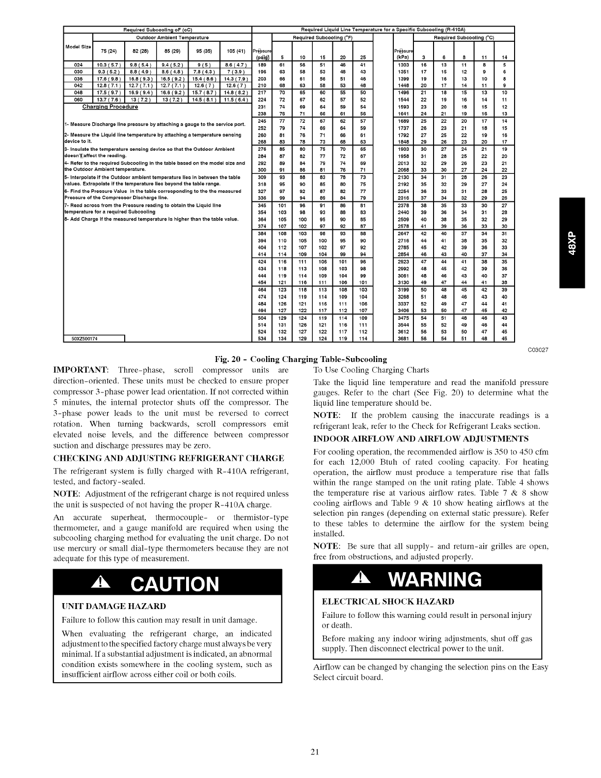
Required Subcoolin_ oF IoC) Required Liquid Line Temperature for aSpecific Subcooting (R-41OA)
Outdoor Ambient Temperature Required Subcooling (°F) Required Subcooling (°C)
Model Size 75 (24) 82 (26) 86 (29) 96 (85)
024 10.3(5.7) 9.8(5.4) 9.4(6.2) 9(5)
030 9.3 ( 5.2 ) 8.8 ( 4.9 ) 8.6 ( 4.8 ) 7.6 ( 4.3 )
036 17.6(9.8) 16.8 (9.3) 16.6 (9.2) 16.4 (6.6)
042 12.8(7.1) 12.7(7.1) 12.7(7.1) 12.6(7)
046 17.5(9.7) 16.9(9.4) 16.6(9.2) 16.7 (6.7)
060 13.7(7.6) 13(7.2) 16(7.2) 14.6 (6.1)
Charqinq Procedure
1- Meacure Di¢charge line preceure by attaching a gauge to the _ervice port.
2- Meacure the Liquid line temperature by attaching a temperature Ceneing
device to it.
3- Ineulate the temperature ceneing device _=o that the Outdoor Ambient
doe_=n'_affect the reading.
105 (41) Pre_sur,
8.6(4.7) 189
7(3.9) 196
14.3(7.9) 203
12.6(7) 210
14.8(8.2) 217
11.5(6.4) 224
231
238
245
252
260
268
276
284
4- Refer to the required Subcooling in the table baeed on the model ¢ize and 292
the Outdoor Ambient temperature. 300
5- Interpolate if the Outdoor ambient temperature lie_ in between the table 309
value€. Extrapolate if the temperature lie€ beyond the table range. 316
6- Find the Pree_ure Value in the table corre¢ponding to the the meaCured 327
Pre¢¢ure of the Compre¢eor Di¢charge line. 336
7- Read acro¢_= from the Preeeure reading to obtain the Liquid line 345
temperature for a required Subcooling 364
8- Add Charge if the meaeured temperature i¢ higher than the table value. 364
374
384
394
4O4
414
424
434
444
454
464
474
464
494
5O4
514
524
50XZ500174 ]534
5
61
63
66
68
70
72
74
76
77
79
81
83
85
87
89
91
93
95
97
99
101
103
105
107
108
110
112
114
116
118
119
121
123
124
126
127
129
131
132
134
Pre_sur_
10 15 20 26 (kPa)
56 51 46 41 1303
58 53 48 43 1351
61 66 51 46 1399
63 68 53 48 1448
66 60 55 50 1496
67 62 57 52 1544
69 64 59 54 1593
71 66 61 56 1641
72 67 62 57 1689
74 69 64 59 1737
76 71 66 61 1792
76 73 68 63 1848
80 78 70 66 1903
82 77 72 67 1956
84 79 74 69 2013
86 61 76 71 2066
88 63 78 73 2130
90 65 80 76 2192
92 67 82 77 2254
94 69 84 79 2316
96 91 86 81 2376
98 93 88 83 2440
100 95 90 86 2509
102 97 92 87 2576
103 98 96 88 2647
106 100 95 90 2716
107 102 97 92 2786
109 104 99 94 2854
111 106 101 96 2923
113 108 103 98 2992
114 109 104 99 3061
116 111 106 101 3130
118 113 108 103 3199
119 114 109 104 3266
121 116 111 106 3337
122 117 112 107 3406
124 119 114 109 3476
126 121 116 111 3544
127 122 117 112 3612
129 124 119 114 3661
3 6 8
16 13 11
17 18 12
19 16 13
20 17 14
21 18 15
22 19 16
23 20 18
24 21 19
26 22 20
26 23 21
27 25 22
29 26 23
30 27 24
31 28 25
32 29 26
33 30 27
34 31 28
36 32 29
36 33 31
37 34 32
38 35 33
39 36 34
40 38 35
41 39 36
42 40 37
44 41 38
45 42 39
46 43 40
47 44 41
46 45 42
46 46 43
49 47 44
50 48 45
51 48 46
52 49 47
53 50 47
54 51 48
55 52 49
56 63 50
56 64 51
11 14
8 5
9 6
10 8
11 9
13 10
14 11
15 12
16 13
17 14
18 15
19 16
20 17
21 19
22 20
23 21
24 22
26 23
27 24
28 25
29 26
30 27
31 28
32 29
33 30
34 31
35 32
36 33
37 34
38 35
39 36
40 37
41 38
42 39
43 40
44 41
45 42
46 43
46 44
47 45
48 45
C03027
Fig. 20 - Cooling Charging Table-Subcooling
IMPORTANT: Three-phase, scroll compressor units are To Use Cooling Charging Charts
direction-oriented. These units must be checked to ensure proper
compressor 3-phase power lead orientation. If not corrected within
5 minutes, the internal protector shuts off the compressor. The
3-phase power leads to the unit must be reversed to correct
rotation. When turning backwards, scroll compressors emit
elevated noise levels, and the difference between compressor
suction and discharge pressures may be zero.
CHECKING AND ADJUSTING REFRIGERANT CHARGE
The refrigerant system is fully charged with R-410A refrigerant,
tested, and factory-sealed.
NOTE: Adjustment of the refrigerant charge is not required unless
the unit is suspected of not having the proper R-410A charge.
An accurate superheat, thermocouple- or thermistor-type
thermometer, and a gauge manifold are required when using the
subcooling charging method for evaluating the unit charge. Do not
use mercury or small dial-type thermometers because they are not
adequate for this type of measurement.
Take the liquid line temperature and read the manifold pressure
gauges. Refer to the chart (See Fig. 20) to determine what the
liquid line temperature should be.
NOTE: If the problem causing the inaccurate readings is a
refrigerant leak, refer to the Check for Refrigerant Leaks section.
INDOOR AIRFLOW AND AIRFLOW ADJUSTMENTS
For cooling operation, the recommended airflow is 350 to 450 cfm
for each 12,000 Btuh of rated cooling capacity. For heating
operation, the airflow must produce a temperature rise that falls
within the range stamped on the unit rating plate. Table 4 shows
the temperature rise at various airflow rates. Table 7 & 8 show
cooling airflows and Table 9 & 10 show heating airflows at the
selection pin ranges (depending on external static pressure). Refer
to these tables to determine the airflow for the system being
installed.
NOTE: Be sure that all supply- and return-air grilles are open,
free from obstructions, and adjusted properly.
UNIT DAMAGE HAZARD
Failure to follow this caution may result in unit damage.
When evaluating the refrigerant charge, an indicated
adjustment to the specified factory charge must always be very
minimal. If a substantial adjustment is indicated, an abnormal
condition exists somewhere in the cooling system, such as
insufficient airflow across either coil or both coils.
ELECTRICAL SHOCK HAZARD
Failure to follow this warning could result in personal iniury
or death.
Before making any indoor wiring adjustments, shut off gas
supply. Then disconnect electrical power to the unit.
Airflow can be changed by changing the selection pins on the Easy
Select circuit board.
21
MAINTENANCE
To ensure continuing high performance and to minimize the
possibility of premature equipment failure, periodic maintenance
must be performed on this equipment. This combination
heating/cooling unit should be inspected at least once each year by
a qualified service person. To troubleshoot cooling or heating of
units, refer to Tables 12, 13 and 14.
NOTE: Consult your local dealer about the availability of a
maintenance contract.
PERSONAL INJURY AND UNIT DAMAGE HAZARD
Failure to follow this warning could result in personal injury
or death and unit component damage.
The ability to properly perform maintenance on this
equipment requires certain expertise, mechanical skills, tools
and equipment. If you do not possess these, do not attempt to
perform any maintenance on this equipment, other than those
procedures recommended in the Owner's Manual.
ELECTRICALSHOCK HAZARD
Failure to follow these warnings could result in personal
iniury or death:
1. Turn off electrical power to the unit before performing
any maintenance or service on this unit.
2. Use extreme caution when removing panels and parts.
3. Never place anything combustible either on or in contact
with the unit.
4. Should overheating occur or the gas supply fail to shut
off, turn off external main manual gas valve to the unit.
Then shut off electrical supply.
UNIT OPERATION HAZARD
Failure to follow this caution may result in improper
operation.
Errors made when reconnecting wires may cause improper
and dangerous operation. Label all wires prior to
disconnecting when servicing.
The minimum maintenance requirements for this equipment are as
follows:
1. Inspect air filter(s) each month. Clean or replace when
necessary. Certain geographical locations may require more
frequent inspections.
2. Inspect indoor coil, outdoor coil, drain pan, and condensate
drain each cooling season for cleanliness. Clean when
necessary.
3. Inspect blower motor and wheel for cleanliness at the
beginning of each heating and cooling season. Clean when
necessary. For first heating and cooling season, inspect
blower wheel bi-monthly to determine proper cleaning
frequency.
4. Check electrical connections for tightness and controls for
proper operation each heating and cooling season. Service
when necessary.
5. Check and inspect heating section before each heating
season. Clean and adjust when necessary.
6. Check flue hood and remove any obstructions, if necessary.
AIR FILTER
NOTE: Never operate the unit without a suitable air filter in the
return-air duct system. Always replace the filter with the same
dimensional size and type as originally installed. (See Table 1 for
recommended filter sizes.)
Inspect air filter(s) at least once each month and replace
(throwaway-type) or clean (cleanable-type) at least twice during
each heating and cooling season or whenever the filter(s) becomes
clogged with dust and/or lint.
EVAPORATOR BLOWER AND MOTOR
NOTE: All motors are prelubricated. Do not attempt to lubricate
these motors.
For longer life, operating economy, and continuing efficiency,
clean accumulated dirt and grease from the blower wheel and
motor annually.
CLEANING THE BLOWER MOTOR AND WHEEL
1. Remove and disassemble blower assembly as follows:
a. Remove unit access panel.
b. Disconnect motor lead from blower relay (BR).
Disconnect yellow lead from terminal L2 of the
contactor.
c. On all units, remove blower assembly from unit.
Remove screws securing blower to blower partition and
slide assembly out. Be careful not to tear insulation in
blower compartment.
d. Ensure proper reassembly by marking blower wheel and
motor in relation to blower housing before disassembly.
e. Loosen setscrew(s) that secures wheel to motor shaft.
Remove screws that secure motor mount brackets to
housing, and slide motor and motor mount out of
housing.
2. Remove and clean blower wheel as follows:
a. Ensure proper reassembly by marking wheel orientation.
b. Lift wheel from housing. When handling and/or
cleaning blower wheel, be sure not to disturb balance
weights (clips) on blower wheel vanes.
c. Remove caked-on dirt from wheel and housing with a
brush. Remove lint and/or dirt accumulations from
wheel and housing with vacuum cleaner, using soft
brush attachment. Remove grease and oil with mild
solvent.
d. Reassemble wheel into housing.
e. Reassemble motor into housing. Be sure setscrews are
tightened on motor shaft flats and not on round part of
shaft.
f. Reinstall unit access panel.
3. Restore electrical power to unit. Start unit and check for
proper blower rotation and motor speeds during heating and
cooling cycles.
FLUE GAS PASSAGEWAYS
To inspect the flue collector box and upper areas of the heat
exchanger:
1. Remove the combustion blower wheel and motor assembly
according to directions in the Combustion-Air Blower
section.
2. Remove the 3 screws holding the blower housing to the flue
collector box cover (See Fig. 23).
3. Remove the 12 screws holding the flue collector box cover
(See Fig. 24) to the heat exchanger assembly. Inspect the
heat exchangers.
4. Clean all surfaces, as required, using a wire brush.
22
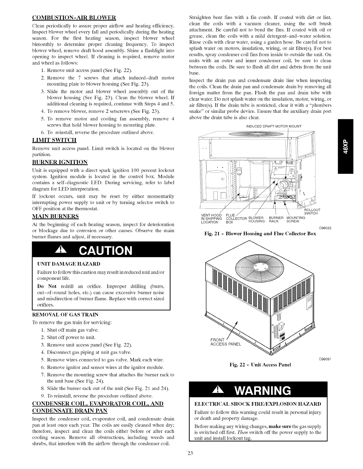
COMBUSTION-AIR BLOWER
Clean periodically to assure proper airfow and heating efficiency.
Inspect blower wheel every fall and periodically during the heating
season. For the first heating season, inspect blower wheel
bimonthly to determine proper cleaning frequency. To inspect
blower wheel, remove draft hood assembly. Shine a flashlight into
opening to inspect wheel. If cleaning is required, remove motor
and wheel as follows:
1. Remove unit access panel (See Fig. 22).
2. Remove the 7 screws that attach induced-draft motor
mounting plate to blower housing (See Fig. 23).
3. Slide the motor and blower wheel assembly out of the
blower housing (See Fig. 23). Clean the blower wheel. If
additional cleaning is required, continue with Steps 4 and 5.
4. To remove blower, remove 2 setscrews (See Fig. 23).
5. To remove motor and cooling fan assembly, remove 4
screws that hold blower housing to mounting plate.
6. To reinstall, reverse the procedure outlined above.
LIMIT SWITCH
Remove unit access panel. Limit switch is located on the blower
partition.
BURNER IGNITION
Unit is equipped with a direct spark ignition 100 percent lockout
system. Ignition module is located in the control box. Module
contains a self-diagnostic LED. During servicing, refer to label
diagram for LED interpretation.
If lockout occurs, unit may be reset by either momentarily
interrupting power supply to unit or by turning selector switch to
OFF position at the thermostat.
MAIN BURNERS
At the beginning of each heating season, inspect for deterioration
or blockage due to corrosion or other causes. Observe the main
burner flames and adjust, if necessary.
Straighten bent fins with a fin comb. If coated with dirt or lint,
clean the coils with a vacuum cleaner, using the soft brush
attachment. Be careful not to bend the fins. If coated with oil or
grease, clean the coils with a mild detergent-and-water solution.
Rinse coils with clear water, using a garden hose. Be careful not to
splash water on motors, insulation, wiring, or air filter(s). For best
results, spray condenser coil fins from inside to outside the unit. On
units with an outer and inner condenser coil, be sure to clean
between the coils. Be sure to flush all dirt and debris from the unit
base.
Inspect the drain pan and condensate drain line when inspecting
the coils. Clean the drain pan and condensate drain by removing all
foreign matter from the pan. Flush the pan and drain tube with
clear water. Do not splash water on the insulation, motor, wiring, or
air filter(s). If the drain tube is restricted, clear it with a "plumbers
snake" or similar probe device. Ensure that the auxiliary drain port
above the drain tube is also clear.
INDUCED DRAFT MOTOR MOUNT
<<v
ROLLOUT
VENT HOOD FLUE SWITCH
IN SHIPPING COLLECTOR BLOWER BURNER MOUNTING
LOCATION BOX HOUSING RACK SCREW
C99022
Fig. 21 - Blower Housing and Flue Collector Box
UNIT DAMAGE HAZARD
Failure to follow this caution may result in reduced unit and/or
component life.
Do Not redrill an orifice. Improper drilling (burrs,
out-of-round holes, etc.) can cause excessive burner noise
and misdirection of burner flame. Replace with correct sized
orifices.
REMOVAL OF GAS TRAIN
To remove the gas train for servicing:
1. Shut off main gas valve.
2. Shut off power to unit.
3. Remove unit access panel (See Fig. 22).
4. Disconnect gas piping at unit gas valve.
5. Remove wires connected to gas valve. Mark each wire.
6. Remove ignitor and sensor wires at the ignitor module.
7. Remove the mounting screw that attaches the burner rack to
the unit base (See Fig. 24).
8. Slide the burner rack out of the unit (See Fig. 21 and 24).
9. To reinstall, reverse the procedure outlined above.
CONDENSER COIL, EVAPORATOR COIL, AND
CONDENSATE DRAIN PAN
Inspect the condenser coil, evaporator coil, and condensate drain
pan at least once each year. The coils are easily cleaned when dry;
therefore, inspect and clean the coils either before or after each
cooling season. Remove all obstructions, including weeds and
shrubs, that interfere with the airflow through the condenser coil.
23
FRONT
ACCESS PANEL
Fig. 22 - Unit Access Panel
C99091
ELECTRICAL SHOCK FIRE/EXPLOSION HAZARD
Failure to follow this warning could result in personal injury
or death and property damage.
Before making any wiring changes, make sure the gas supply
is switched off first. Then switch off the power supply to the
unit and install lockout tag.
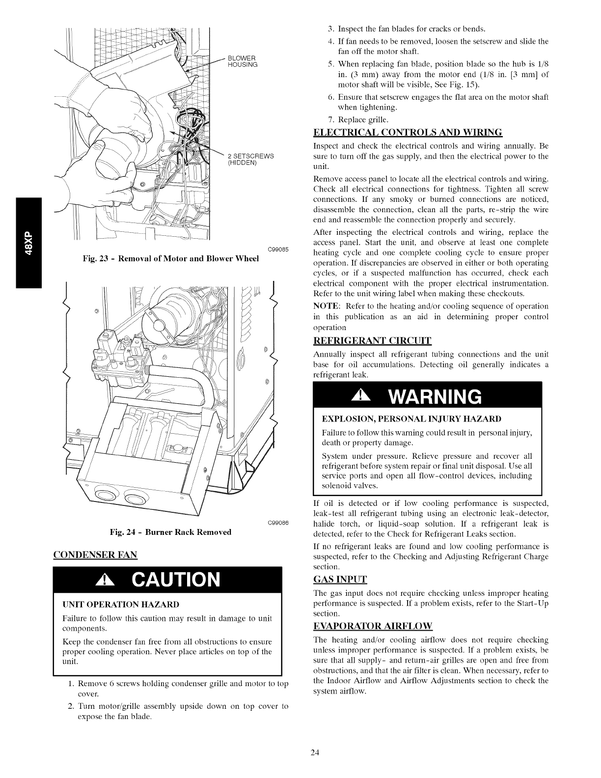
BLOWER
HOUSING
2 SETSCREWS
(HIDDEN)
C99085
Fig. 23 -Removal of Motor and Blower Wheel
Fig. 24 -Burner Rack Removed
CONDENSER FAN
C99086
UNIT OPERATION HAZARD
Failure to follow this caution may result in damage to unit
components.
Keep the condenser fan free from all obstructions to ensure
proper cooling operation. Never place articles on top of the
unit.
1. Remove 6 screws holding condenser grille and motor to top
cover.
2. Turn motor/grille assembly upside down on top cover to
expose the fan blade.
3. Inspect the fan blades for cracks or bends.
4. If fan needs to be removed, loosen the setscrew and slide the
fan off the motor shaft.
5. When replacing fan blade, position blade so the hub is 1/8
in. (3 ram) away from the motor end (1/8 in. [3 ram] of
motor shaft will be visible, See Fig. 15).
6. Ensure that setscrew engages the flat area on the motor shaft
when tightening.
7. Replace grille.
ELECTRICAL CONTROLS AND WIRING
Inspect and check the electrical controls and wiring annually. Be
sure to turn off the gas supply, and then the electrical power to the
unit.
Remove access panel to locate all the electrical controls and wiring.
Check all electrical connections for tightness. Tighten all screw
connections. If any smoky or burned connections are noticed,
disassemble the connection, clean all the parts, re-strip the wire
end and reassemble the connection properly and securely.
After inspecting the electrical controls and wiring, replace the
access panel. Start the unit, and observe at least one complete
heating cycle and one complete cooling cycle to ensure proper
operation. If discrepancies are observed in either or both operating
cycles, or if a suspected malfunction has occurred, check each
electrical component with the proper electrical instrumentation.
Refer to the unit wiring label when making these checkouts.
NOTE: Refer to the heating and/or cooling sequence of operation
in this publication as an aid in deternfining proper control
operation
REFRIGERANT CIRCUIT
Annually inspect all refrigerant tubing connections and the unit
base for oil accumulations. Detecting oil generally indicates a
refrigerant leak.
EXPLOSION, PERSONAL INJURY HAZARD
Failure to follow this warning could result in personal iniury,
death or property damage.
System under pressure. Relieve pressure and recover all
refrigerant before system repair or final unit disposal. Use all
service ports and open all flow-control devices, including
solenoid valves.
If oil is detected or if low cooling performance is suspected,
leak-test all refrigerant tubing using an electronic leak-detector,
halide torch, or liquid-soap solution. If a refrigerant leak is
detected, refer to the Check for Refrigerant Leaks section.
If no refrigerant leaks are found and low cooling performance is
suspected, refer to the Checking and Adjusting Refrigerant Charge
section.
GAS INPUT
The gas input does not require checking unless improper heating
performance is suspected. If a problem exists, refer to the Start-Up
section.
EVAPORATOR AIRFLOW
The heating and/or cooling airflow does not require checking
unless improper performance is suspected. If a problem exists, be
sure that all supply- and return-air grilles are open and free from
obstructions, and that the air filter is clean. When necessary, refer to
the Indoor Airflow and Airflow Adjustments section to check the
system airflow.
24
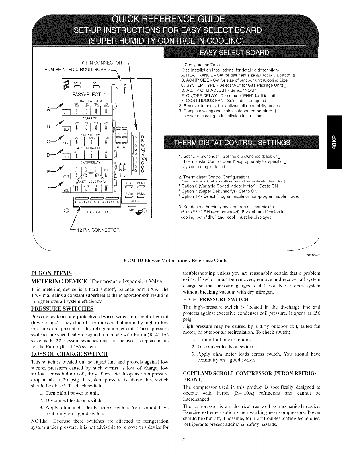
9 PIN CONNECTOR --
ECM PRINTED CIRCUIT BOARD --.___
SEC1 SEC2
C:_ C:3
EASYSELECT TM
GAS HEAT/CFM
1!&
AJ_ _° _i°° _° _0_0__
AC/PPSIZE
0;
,, SYSTEM TYPE
C ,,....._ O___ _; HPO0_ ........
,,, ACiHP CFMADJUST
Q, DH
R
,_ W_
1. Configuration Taps
(See Installation Instructions, for detailed description)
A. HEAT RANGE - Set for gas heat size (EX:090for unit 048090---)D
B. AC/HP SIZE - Set for size of outdoor unit (Cooling Size)
C. SYSTEM TYPE - Select "AC" for Gas Package UnitsN
D. AC/HP CFM ADJUST - Select "NOM"
E. ON/OFF DELAY - Do not use "ENH" for this unit
F. CONTINUOUS FAN - Select desired speed
2. Remove Jumper J1 to activate all dehumidify modes
3. Complete wiring and install outdoor temperature [B
sensor according to Installation Instructions
D._., _
E_..i I
F--_
_ Y_
ON/OFF DELAY _ G
"o o
_ _ _ E÷ _ _c
AUX1 HUM1
AOX_N_M_
O
Z12 PIN CONNECTOR
1. Set "DIP Switches" - Set the dip switches (back of [q
Thermidistat Control Board) appropriately for specific n
system being installed.
2. Thermidistat Control Configurations
(See Thermidistat Control installation Instructions for detailed description)_
* Option 5 (Variable Speed Indoor Motor) - Set to ON
* Option 7 (Super Dehumidify) - Set to ON
* Option 17 - Select Programmable or non-programmable mode.
3. Set desired humidity level on fron of Thermidistat
(50 to 55 % RH recommended). For dehumidification in
cooling, both "dhu" and "cool" must be displayed.
ECM ID Blower Motor-quick Reference Guide
J
C01034G
PURON ITEMS
METERING DEVICE (Thermostatic Expansion Valve )
This metering device is a hard shutoff, balance port TXV. The
TXV maintains a constant superheat at the evaporator exit resulting
in higher overall system efficiency.
PRESSURE SWITCHES
Pressure switches are protective devices wired into control circuit
(low voltage). They shut off compressor if abnormally high or low
pressures are present in the refrigeration circuit. These pressure
switches are specifically designed to operate with Puron (R-410A)
systems. R-22 pressure switches must not be used as replacements
for the Puron (R-410A) system.
LOSS OF CHARGE SWITCH
This switch is located on the liquid line and protects against low
suction pressures caused by such events as loss of charge, low
airflow across indoor coil, dirty filters, etc. It opens on a pressure
drop at about 20 psig. If system pressure is above this, switch
should be closed. To check switch:
1. Turn off all power to unit.
2. Disconnect leads on switch.
3. Apply ohm meter leads across switch. You should have
continuity on a good switch.
NOTE: Because these switches are attached to refrigeration
system under pressure, it is not advisable to remove this device for
troubleshooting unless you are reasonably certain that a problem
exists. If switch must be removed, remove and recover all system
charge so that pressure gauges read 0 psi. Never open system
without breaking vacuum with dry nitrogen.
HIGH-PRESSURE SWITCH
The high-pressure switch is located in the discharge line and
protects against excessive condenser coil pressure. It opens at 650
psig.
High pressure may be caused by a dirty outdoor coil, failed fan
motor, or outdoor air recirculation. To check switch:
1. Turn off all power to unit.
2. Disconnect leads on switch.
3. Apply ohm meter leads across switch. You should have
continuity on a good switch.
COPELAND SCROLL COMPRESSOR (PURON REFRIG-
ERANT)
The compressor used in this product is specifically designed to
operate with Puron (R-410A) refrigerant and cannot be
interchanged.
The compressor is an electrical (as well as mechanical) device.
Exercise extreme caution when working near compressors. Power
should be shut off, if possible, for most troubleshooting techniques.
Refrigerants present additional safety hazards.
25
FIRE/EXPLOSIONHAZARD
Failuretofollowthiswarningcouldresultinpersonalinjury
ordeathand/orpropertydamage.
Wearsafetyglassesandgloveswhenhandlingrefrigerants.
Keeptorchesandotherignitionsourcesawayfrom
refrigerantsandoils.
Thescrollcompressorpumpsrefrigerantthroughoutthesystemby
theinteractionof astationaryandanorbitingscroll.Thescroll
compressorhasnodynanficsuctionordischargevalves,andit is
moretolerantof stressescausedbydebris,liquidslugging,and
floodedstarts.Thecompressorisequippedwithananti-rotational
deviceandaninternalpressurereliefport.Theanti-rotational
devicepreventsthescrollfromturningbackwardsandreplacesthe
needforacycleprotector.Thepressurereliefportisasafety
device,designedtoprotectagainstextremehighpressure.The
reliefporthasanoperatingrangebetween550and625psi
differentialpressure.
UNITOPERATIONANDSAFETYHAZARD
Failuretofollowthiswarningcouldresultinpersonalinjury
orequipmentdamage.
ThissystemusesPuron(R-410A)refrigerantwhichhas
higheroperatingpressuresthanR-22andotherrefrigerants.
Nootherrefrigerantmaybeusedinthissystem.Gaugeset,
hoses,andrecoverysystemnmstbedesignedtohandlePuron.
Ifyouareunsure,consulttheequipmentmanufacturer.
REFRIGERANTSYSTEM
Thisinformationcoverstherefrigerantsystemof the48XP,
includingthecompressoroilneeded,servicingsystemsonroofs
containingsyntheticmaterials,thefilterdrierandrefrigerant
charging.
CompressorOil
TheCopelandscrollcompressoruses3MAFPOEoil.Ifadditional
oil is needed,useUniqemaRL32-3MAF.If thisoil is not
availaMe,useCopelandUltra32CCorMobilArcticEAL22CC.
Thisoil is extremelyhygroscopic,meaningit absorbswater
readily.Thisoil isextremelyhygroscopic,meaningit absorbs
waterreadily.POEoilscanabsorb15timesasmuchwaterasother
oilsdesignedforHCFCandCFCrefrigerants.Takeallnecessary
precautionstoavoidexposureoftheoiltotheatmosphere.
SERVICINGSYSTEMSONROOFSWITHSYNTHETIC-
MATERIALS
POE(polyolester)compressorlubricantsareknowntocauselong
termdamagetosomesyntheticroofingmaterials.
Exposure,evenif immediatelycleanedup, may cause
embrittlement(leadingtocracking)tooccurinoneyearormore.
Whenperforminganyservicethatmayriskexposureof
compressoroiltotheroof,takeappropriateprecautionstoprotect
roofing.Procedureswhichriskoilleakageinclude,butarenot
limitedto,compressorreplacement,repairingrefrigerantleaks,
replacingrefrigerantcomponentssuchasfilterdrier,pressure
switch,meteringdevice,coil,accumulator,orreversingvalve.
SyntheticRoofPrecautionaryProcedure
1.Coverextendedroofworkingareawithanimpermeable
polyethylene(plastic)drip clothor tarp.Coveran
approximate10X10ft.(3X3m)area.
2.Coverareainfrontoftheunitservicepanelwithaterry
clothshoptowelto absorblubricantspillsandprevent
run-offs,andprotectdropclothfromtearscausedbytools
orcomponents.
3.Placeterryclothshoptowelinsideunitimmediatelyunder
component(s)tobeservicedandpreventlubricantrun-offs
throughthelouveredopeningsintheunitbase.
4.Performrequiredservice.
5.Removeanddisposeofanyoilcontaminatedmaterialper
localcodes.
LIQUIDLINEFILTERDRIER
ThisfilterdrierisspecificallydesignedtooperatewithPuron.Use
onlyfactory-authorizedcomponents.Filterdriermustbereplaced
whenevertherefrigerantsystemisopened.Whenremovingafilter
drier,useatubingcuttertocutthedrierfromthesystem.Donot
unsweatafilterdrierfromthesystem.Heatfromunsweatingwill
releasemoistureandcontanfinantsfromdrierintosystem.
PURON(R-410A)REFRIGERANTCHARGING
Refertounitinformationplateandchargingchart.SomeR-410A
refrigerantcylinderscontainadiptubetoallowliquidrefrigerantto
flowfromcylinderin uprightposition.Forcylindersequipped
withadiptube,chargePuronunitswithcylinderin upright
positionandacommercialmeteringdevicein manifoldhose.
Chargerefrigerantintosuction-line.
TROUBLESHOOTING
Use the Troubleshooting Guides (See Tables 12-14) if problems
occur with these units.
START-UP CHECKLIST
Use Start-Up checklist to ensure proper start-up procedures are
followed.
26
PURON® (R-410A) QUICK REFERENCE GUIDE
• Puron refrigerant operates at 50-70 percent higher pressures than R-22. Be sure that servicing equipment and replacement
components are designed to operate with Puron
• Puron refrigerant cylinders are rose colored.
• Recovery cylinder service pressure rating must be 400 psig, DOT 4BA400 or DOT BW400.
• Puron systems should be charged with liquid refrigerant. Use a commercial type metering device in the manifold hose when
charging into suction line with compressor operating
• Manifold sets should be 700 psig high side and 180 psig low side with 550 psig low-side retard.
• Use hoses with 700 psig service pressure rating.
• Leak detectors should be designed to detect HFC refrigerant.
• Puron, as with other HFCs, is only compatible with POE oils.
• Vacuum pumps will not remove moisture from oil.
• Do not use liquid-line filter driers with rated working pressures less than 600 psig.
• Do not leave Puron suction line filter driers in line longer than 72 hrs.
• Do not install a suction-line filter drier in liquid line.
• POE oils absorb moisture rapidly. Do not expose oil to atmosphere.
• POE oils may cause damage to certain plastics and roofing materials.
• Wrap all filter driers and service valves with wet cloth when brazing.
• A factory approved liquid-line filter drier is required on every unit.
• Do NOT use an R-22 TXV.
• If indoor unit is equipped with an R-22 TXV or piston metering device, it must be changed to a hard shutoff Puron TXV.
• Never open system to atmosphere while it is under a vacuum.
• When system must be opened for service, recover refrigerant, evacuate then break vacuum with dry nitrogen and replace filter
driers. Evacuate to 500 microns prior to recharging.
• Do not vent Puron into the atmosphere.
• Do not use capillary tube coils.
• Observe all warnings, cautions, and bold text.
• All indoor coils must be installed with a hard shutoff Puron TXV metering device.
27
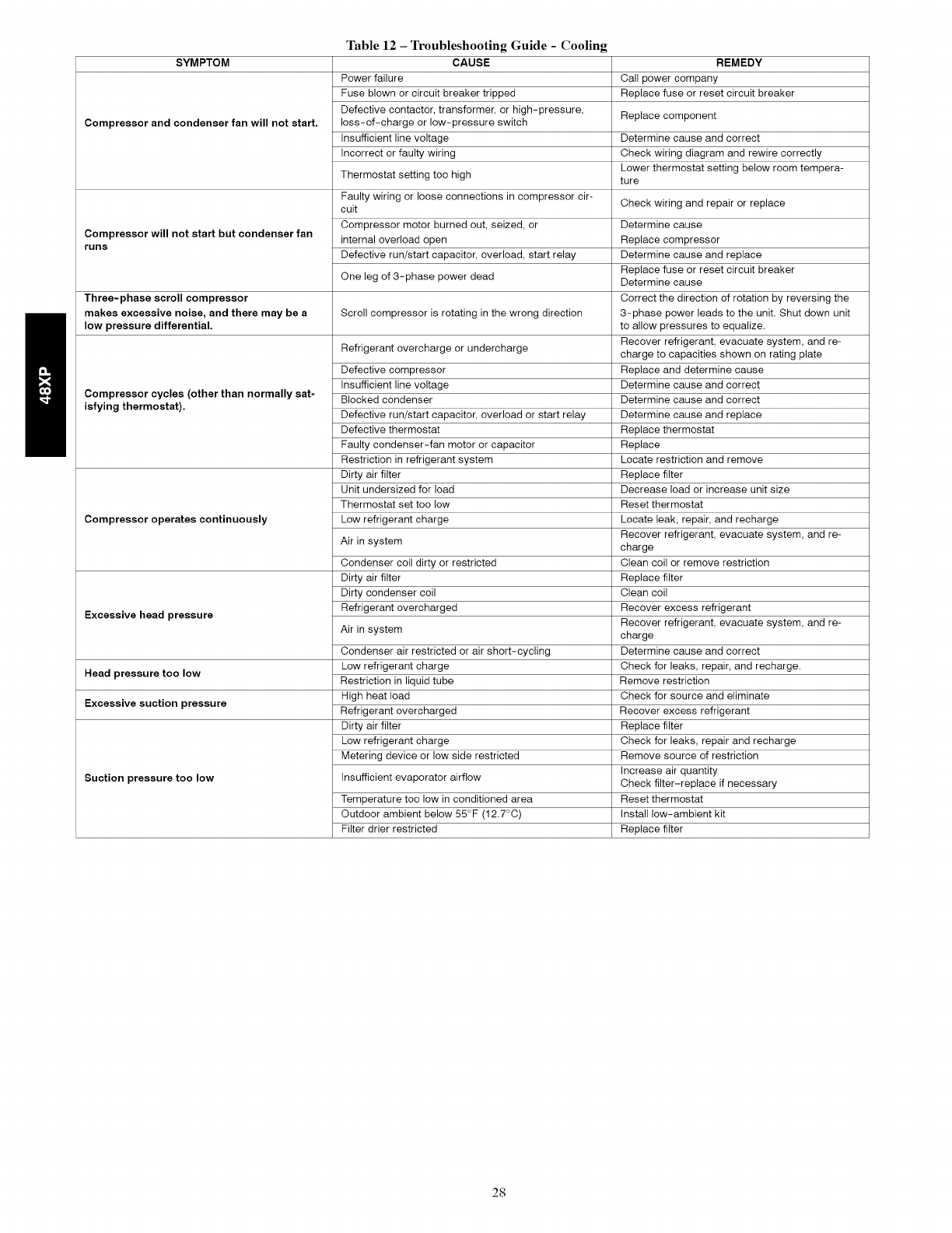
SYMPTOM
Compressor and condenser fan will not start.
Compressor will not start but condenser fan
runs
Table 12 -Troubleshooting Guide - Cooling
CAUSE
Power failure
Fuse blown or circuit breaker tripped
Defective contactor, transformer, or high-pressure,
loss-of-charge or low-pressure switch
Insufficient line voltage
Incorrect or faulty wiring
Thermostat setting too high
Faulty wiring or loose connections in compressor cir-
cuit
Compressor motor burned out, seized, or
internal overload open
Defective run/start capacitor, overload, start relay
One leg of 3-phase power dead
Three-phase scroll compressor
makes excessive noise, and there may be a Scroll compressor is rotating in the wrong direction
low pressure differential.
Refrigerant overcharge or undercharge
Compressor cycles (other than normally sat-
isfying thermostat).
Compressor operates continuously
Excessive head pressure
Head pressure too low
Excessive suction pressure
Suction pressure too low
Defective compressor
Insufficient line voltage
Blocked condenser
Defective run/start capacitor, overload or start relay
Defective thermostat
Faulty condenser-fan motor or capacitor
Restriction in refrigerant system
Dirty air filter
Unit undersized for load
Thermostat set too low
Low refrigerant charge
Air in system
Condenser coil dirty or restricted
Dirty air filter
Dirty condenser coil
Refrigerant overcharged
Air in system
Condenser air restricted or air short-cycling
Low refrigerant charge
Restriction in liquid tube
High heat load
Refrigerant overcharged
Dirty air filter
Low refrigerant charge
Metering device or low side restricted
Insufficient evaporator airflow
Temperature too low in conditioned area
Outdoor ambient below 55°F (12.7°C)
Filter drier restricted
REMEDY
Call power company
Replace fuse or reset circuit breaker
Replace component
Determine cause and correct
Check wiring diagram and rewire correctly
Lower thermostat setting below room tempera-
ture
Check wiring and repair or replace
Determine cause
Replace compressor
Determine cause and replace
Replace fuse or reset circuit breaker
Determine cause
Correct the direction of rotation by reversing the
3-phase power leads to the unit. Shut down unit
to allow pressures to equalize.
Recover refrigerant, evacuate system, and re-
charge to capacities shown on rating plate
Replace and determine cause
Determine cause and correct
Determine cause and correct
Determine cause and replace
Replace thermostat
Replace
Locate restriction and remove
Replace filter
Decrease load or increase unit size
Reset thermostat
Locate leak, repair, and recharge
Recover refrigerant, evacuate system, and re-
charge
Clean coil or remove restriction
Replace filter
Clean coil
Recover excess refrigerant
Recover refrigerant, evacuate system, and re-
charge
Determine cause and correct
Check for leaks, repair, and recharge.
Remove restriction
Check for source and eliminate
Recover excess refrigerant
Replace filter
Check for leaks, repair and recharge
Remove source of restriction
Increase air quantity
Check filter-replace if necessary
Reset thermostat
Install low-ambient kit
Replace filter
28
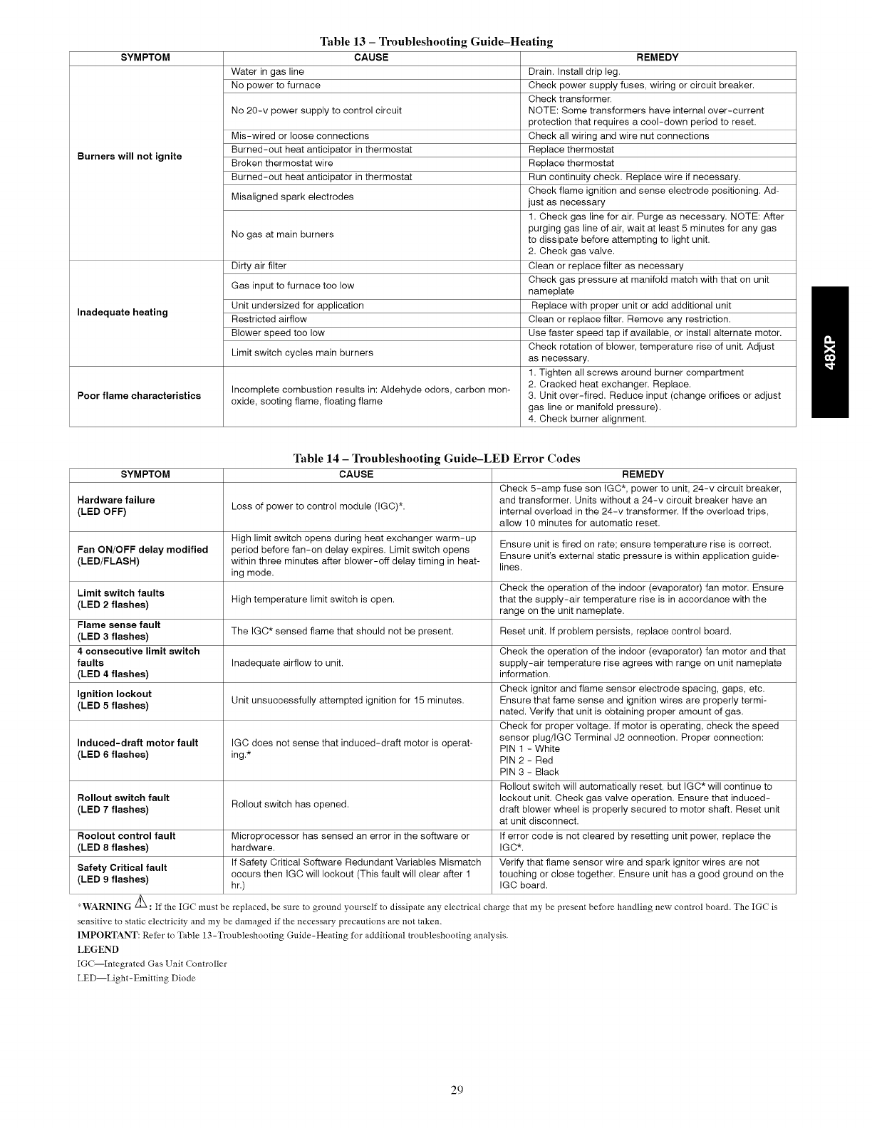
Table 13 - Troubleshooting Guide-Heating
SYMPTOM CAUSE REMEDY
Water in gas line Drain. Install drip leg.
No power to furnace Check power supply fuses, wiring or circuit breaker.
Check transformer.
No 20-v power supply to control circuit NOTE: Some transformers have internal over-current
protection that requires a cool-down period to reset.
Mis-wired or loose connections Check all wiring and wire nut connections
Burned-out heat anticipator in thermostat Replace thermostat
Burners will not ignite Broken thermostat wire Replace thermostat
Burned-out heat anticipator in thermostat Run continuity check. Replace wire if necessary.
Check flame ignition and sense electrode positioning. Ad-
Misaligned spark electrodes just as necessary
1. Check gas line for air. Purge as necessary. NOTE: After
purging gas line of air, wait at least 5 minutes for any gas
No gas at main burners to dissipate before attempting to light unit.
2. Check gas valve.
Dirty air filter Clean or replace filter as necessary
Check gas pressure at manifold match with that on unit
Gas input to furnace too low nameplate
Unit undersized for application Replace with proper unit or add additional unit
Inadequate heating Restricted airflow Clean or replace filter. Remove any restriction.
Blower speed too low Use faster speed tap if available, or install alternate motor.
Check rotation of blower, temperature rise of unit. Adjust
Limit switch cycles main burners as necessary.
1. Tighten all screws around burner compartment
Incomplete combustion results in: Aldehyde odors, carbon mon- 2. Cracked heat exchanger. Replace.
Poor flame characteristics oxide, sooting flame, floating flame 3. Unit over-fired. Reduce input (change orifices or adjust
gas line or manifold pressure).
4. Check burner alignment.
Table 14 - Troubleshooting Guide-LED Error Codes
SYMPTOM CAUSE REMEDY
Check 5-amp fuse son IGC*, power to unit, 24-v circuit breaker,
Hardware failure and transformer. Units without a 24-v circuit breaker have an
(LED OFF) Loss of power to control module (IGC)*. internal overload in the 24-v transformer. If the overload trips,
allow 10 minutes for automatic reset.
High limit switch opens during heat exchanger warm-up Ensure unit is fired on rate; ensure temperature rise is correct.
Fan ON/OFF delay modified period before fan-on delay expires. Limit switch opens
(LED/FLASH) within three minutes after blower-off delay timing in heat- Ensure unit's external static pressure is within application guide-
ing mode. lines.
Limit switch faults Check the operation of the indoor (evaporator) fan motor. Ensure
(LED 2 flashes) High temperature limit switch is open. that the supply-air temperature rise is in accordance with the
range on the unit nameplate.
Flame sense fault The IGC* sensed flame that should not be present. Reset unit. If problem persists, replace control board.
(LED 3flashes)
4 consecutive limit switch Check the operation of the indoor (evaporator) fan motor and that
faults Inadequate airflow to unit. supply-air temperature rise agrees with range on unit nameplate
(LED 4 flashes) information.
Check ignitor and flame sensor electrode spacing, gaps, etc.
Ignition lockout Unit unsuccessfully attempted ignition for 15 minutes. Ensure that fame sense and ignition wires are properly termi-
(LED 5 flashes) nated. Verify that unit is obtaining proper amount of gas.
Check for proper voltage. If motor is operating, check the speed
sensor plug/IGC Terminal J2 connection. Proper connection:
Induced-draft motor fault IGC does not sense that induced-draft motor is operat- PIN 1 - White
(LED 6 flashes) ing.* PIN 2 - Red
PIN 3 - Black
Rollout switch will automatically reset, but IGC will continue to
Rollout switch fault lockout unit. Check gas valve operation. Ensure that induced-
(LED 7 flashes) Rollout switch has opened, draft blower wheel is properly secured to motor shaft. Reset unit
at unit disconnect.
Roolout control fault Microprocessor has sensed an error in the software or If error code is not cleared by resetting unit power, replace the
(LED 8 flashes) hardware. IGC*.
If Safety Critical Software Redundant Variables Mismatch Verify that flame sensor wire and spark ignitor wires are not
Safety Critical fault occurs then IGC will lockout (This fault will clear after 1 touching or close together. Ensure unit has a good ground on the
(LED 9 flashes) hr.) IGC board.
*WARNING _ :If the IGC must be replaced, be sure to ground yourself to dissipate any electrical charge that my be present before handling new control board. The IGC is
sensitive to static electricity and my be damaged if the necessary precautions are not taken.
IMPORTANT: Refer to Table 13-Troubleshooting Guide-Heating for additional troubleshooting analysis.
LEGEND
IGC--Integrated Gas Unit Controller
LED--Light-Emitting Diode
29
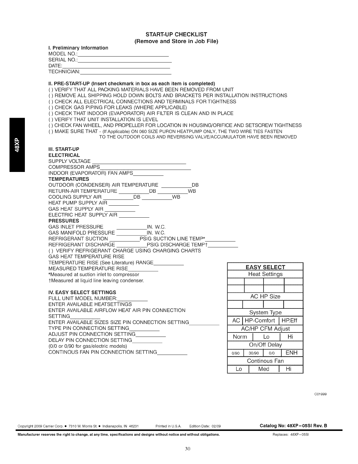
I, Preliminary information
MODEL NO.:
SERIAL NO.:
DATE:
TECHNICIAN:
START=UP CHECKLIST
(Remove and Store in Job File)
II. PRE-START-UP (insert checkmark in box as each item is completed)
VERIFYTHAT ALL PACKING MATERIALS HAVE BEEN REMOVED FROM UNIT
REMOVE ALL SHIPPING HOLD DOWN BOLTS AND BRACKETS PER INSTALLATION INSTRUCTIONS
CHECK ALL ELECTRICAL CONNECTIONS AND TERMINALS FOR TIGHTNESS
CHECK GAS PiPiNG FOR LEAKS (WHERE APPLICABLE)
CHECK THAT INDOOR (EVAPORATOR) AiR FILTER IS CLEAN AND iN PLACE
VERIFY THAT UNIT INSTALLATION IS LEVEL
( ) CHECK FAN WHEEL, AND PROPELLER FOR LOCATION iN HOUSING/ORIFICE AND SETSCREW TIGHTNESS
( ) MAKE SURE THAT - (If Applicable) ON 060 SIZE PURON HEATPUMP ONLY, THE TWO WIRE TIES FASTEN
TO THE OUTDOOR COILS AND REVERSING VALVE/ACCUMULATOR HAVE BEEN REMOVED
ill. START-UP
ELECTRICAL
SUPPLY VOLTAGE
COMPRESSOR AMPS
INDOOR (EVAPORATOR) FAN AMPS
TEMPERATURES
OUTDOOR (CONDENSER) AiR TEMPERATURE DB
RETURN-AIR TEMPERATURE DB WB
COOLING SUPPLY AiR DB WB
HEAT PUMP SUPPLY AiR
GAS HEAT SUPPLY AiR
ELECTRIC HEAT SUPPLY AiR
PRESSURES
GAS INLET PRESSURE
GAS MANIFOLD PRESSURE
REFRIGERANT SUCTION
REFRIGERANT DISCHARGE
( ) VERIFY REFRIGERANT CHARGE USING CHARGING CHARTS
GAS HEAT TEMPERATURE RISE
TEMPERATURE RISE (See Literature) RANGE
MEASURED TEMPERATURE RISE
*Measured at suction inlet to compressor
1-Measured at liquid line leaving condenser.
IN. W.C.
IN, W.C.
PSIG SUCTION LINE TEMP*
PSIG DISCHARGE TEMPt
iV. EASY SELECT SETTINGS
FULL UNIT MODEL NUMBER:
ENTER AVAILABLE HEATSETTINGS
ENTER AVAILABLE AIRFLOVV HEAT AIR PIN CONNECTION
SETTING
ENTER AVAILABLE SIZES SIZE PiN CONNECTION SETTING
TYPE PIN CONNECTION SETTING
ADJUST PiN CONNECTION SETTING
DELAY PIN CONNECTION SETTING
(0/0 or 0/90 for gas/electric models)
CONTiNOUS FAN PiN CONNECTION SETTING
EASY SELECT
Heat Settings
AC HP Size
System Type
A_ HP-Comfort I HP.Eff
AC/HP CFM Adjust
Norm I Lo I Hi
On/Off Delay
0/90 I 30/90 i 0/0 I ENH
Continous Fan
_ I Med ] HI
C01999
Copyright 2009 Carrier Corp, • 7310 W, Morris St. • Indianapolis, IN 46231 Printed in U,S,A, Edition Date: 02/09
Manufacturer reserve8 the right to change, at any time, specification8 and design8 without notice and without obligations,
Catalog No: 48XP-05SI Rev. B
Replaces: 48XP-05SI
30
