Carrier 50ZP042300 User Manual PACKAGE UNIT Manuals And Guides L1003132
CARRIER Package Units(both units combined) Manual L1003132 CARRIER Package Units(both units combined) Owner's Manual, CARRIER Package Units(both units combined) installation guides
User Manual: Carrier 50ZP042300 50ZP042300 CARRIER PACKAGE UNIT - Manuals and Guides View the owners manual for your CARRIER PACKAGE UNIT #50ZP042300. Home:Heating & Cooling Parts:Carrier Parts:Carrier PACKAGE UNIT Manual
Open the PDF directly: View PDF ![]() .
.
Page Count: 20
turn to the expe_
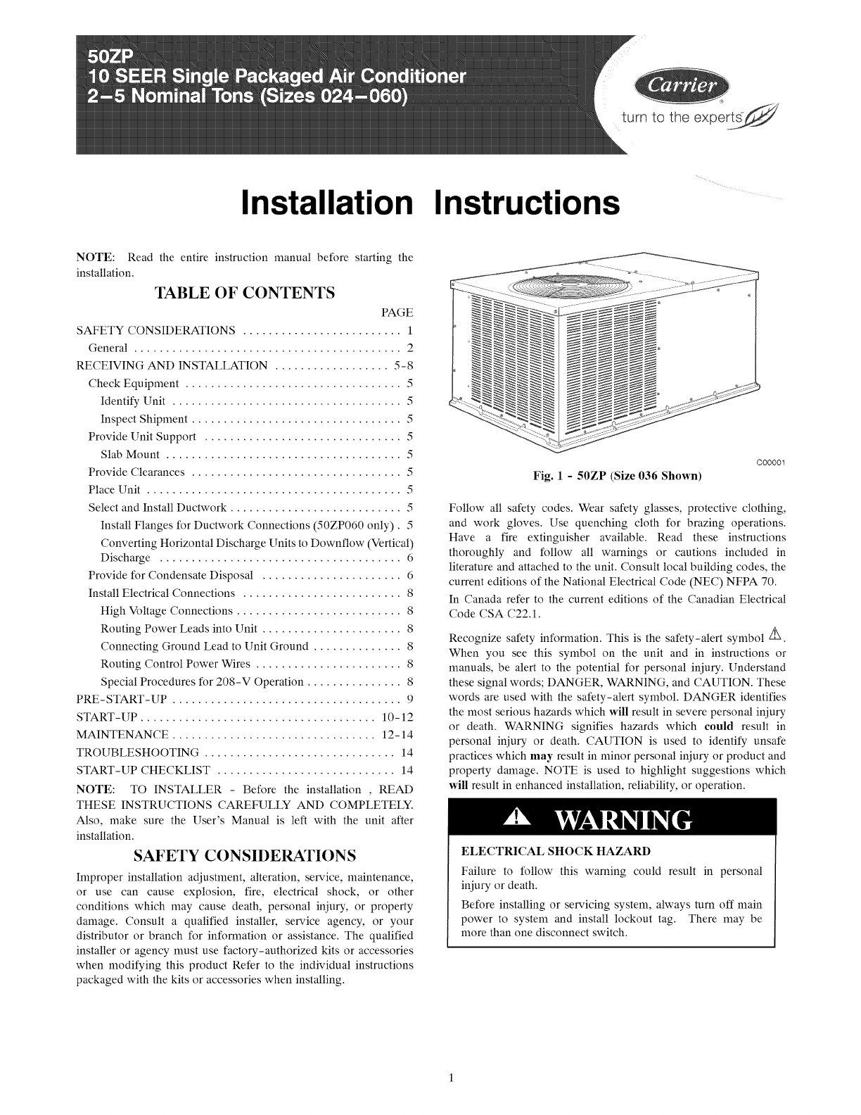
Installation Instructions
NOTE: Read the entire instruction manual before starting the
installation.
TABLE OF CONTENTS
PAGE
SAFETY CONSIDERATIONS ......................... 1
General .......................................... 2
RECEIVING AND INSTALLATION .................. 5-8
Check Equipment .................................. 5
Identify Unit .................................... 5
Inspect Shipment ................................. 5
Provide Unit Support ............................... 5
Slab Mount ..................................... 5
Provide Clearances ................................. 5
Place Unit ........................................ 5
Select and Install Ductwork ........................... 5
Install Flanges for Ductwork Connections (50ZP060 only). 5
Converting Horizontal Discharge Units to Downflow (Vertical)
Discharge ...................................... 6
Provide for Condensate Disposal ...................... 6
Install Electrical Connections ......................... 8
High Voltage Connections .......................... 8
Routing Power Leads into Unit ...................... 8
Connecting Ground Lead to Unit Ground .............. 8
Routing Control Power Wires ....................... 8
Special Procedures for 208-V Operation ............... 8
PRE-START-UP .................................... 9
START-UP ..................................... 10-12
MAINTENANCE ................................ 12-14
TROUBLESHOOTING .............................. 14
START-UP CHECKLIST ............................ 14
NOTE: TO INSTALLER - Before the installation , READ
THESE INSTRUCTIONS CAREFULLY AND COMPLETELY.
Also, make sure the User's Manual is left with the unit after
installation.
SAFETY CONSIDERATIONS
Improper installation adjustment, alteration, service, maintenance,
or use can cause explosion, fire, electrical shock, or other
conditions which may cause death, personal injury, or property
damage. Consult a qualified installer, service agency, or your
distributor or branch for information or assistance. The qualified
installer or agency must use factory-authorized kits or accessories
when modifying this product Refer to the individual instructions
packaged with the kits or accessories when installing.
Fig. 1 - 50ZP (Size 036 Shown)
C00001
Follow all safety codes. Wear safety glasses, protective clothing,
and work gloves. Use quenching cloth for brazing operations.
Have a fire extinguisher available. Read these instructions
thoroughly and follow all warnings or cautions included in
literature and attached to the unit. Consult local building codes, the
current editions of the National Electrical Code (NEC) NFPA 70.
In Canada refer to the current editions of the Canadian Electrical
Code CSA C22.1.
Recognize safety information. This is the safety-alert symbol Z_
When you see this symbol on the unit and in instructions or
manuals, be alert to the potential for personal iniury. Understand
these signal words; DANGER, WARNING, and CAUTION. These
words are used with the safety-alert symbol. DANGER identifies
the most serious hazards which will result in severe personal iniury
or death. WARNING signifies hazards which could result in
personal iniury or death. CAUTION is used to identify unsafe
practices which may result in minor personal iniury or product and
property damage. NOTE is used to highlight suggestions which
will result in enhanced installation, reliability, or operation.
ELECTRICAL SHOCK HAZARD
Failure to follow this warning could result in personal
iniury or death.
Before installing or servicing system, always turn off main
power to system and install lockout tag. There may be
more than one disconnect switch.
COND
COl Lm\\
11.57
[294.0]
16.06
_ [408.0]
REAR VIEW
\\\L 14.0 DtA.
[356,0]
DUCT OPENINGS
50.98
[1295.0]
II
II
II
II
II
I'I
II
II
II
II
II
\
BOTTOM OF UNI r
EVAP COIL_
f \ L
\\
\\\\
\\\\
_CG
, ,, ,, ,
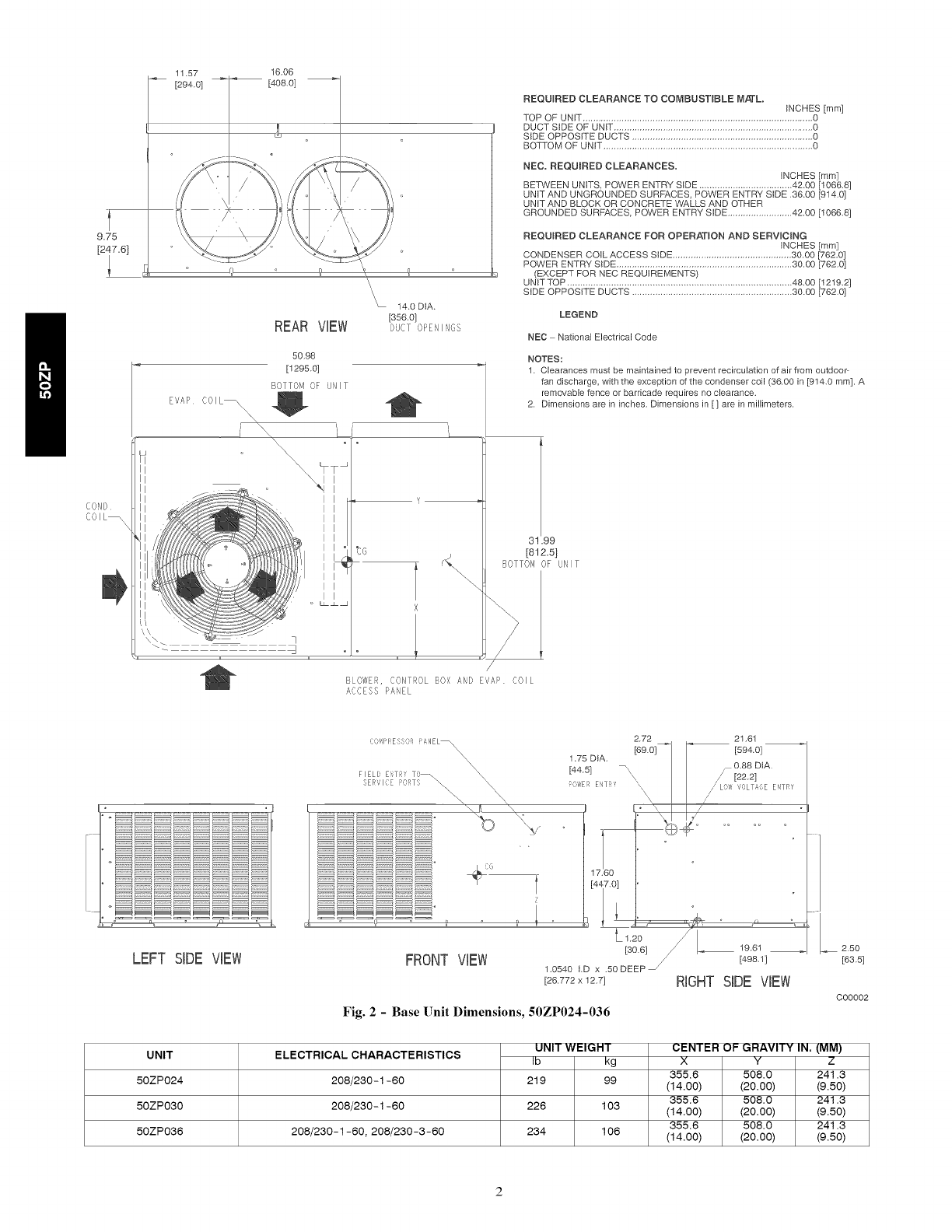
REQUIRED CLEARANCE TO COMBUSTIBLE M,_'L,
INCHES [ram]
TOP OF UNIT ......................................................................................... 0
DUCT StDE OF UNtT ............................................................................. 0
SIDE OPPOSITE DUCTS ...................................................................... 0
BOTTOM OF UNIT ................................................................................. 0
NEe, REQUIRED CLEARANCES,
INCHES [mini
BETWEEN UNITS, POWER ENTRY SIDE .................................... 42.00 [108&8]
UNIT AND UNGROUNDED SURFACES, POWER ENTRY SIDE ,38.00 [914,0}
UNtT AND BLOCK OR CONCRETE WALLS AND OTHER
GROUNDED SURFACES, POWER ENTRY SIDE ......................... 42.00 [1088.8]
REQUIRED CLEARANCE FOR OPERATION AND SERVICING
INCHES [mini
CONDENSER COIL ACCESS SIDE .............................................. 30,00 [782.0]
POWER ENTRY SIDE .................................................................... 30,00 [782.0]
(EXCEPT FOR NEC REQUIREMENTS)
UNIT TOP ....................................................................................... 48.00 [1219.2]
SIDE OPPOSITE DUCTS .............................................................. 30.00 [782,0}
LEGEND
NED National Electrical Code
NOTES:
1. Clearances must be maintained to prevent recirculation of air from outdoop
fan discharge with the exception of the condenser coil (38,00 in [914.0 mm], A
removable fence or barricade requires no clearance.
2, Dimensions are in inches, Dimensions in [] are in millimeters,
3! .99
[812.5}
BOTrO/! OF UNIT
BLOWER, CONTROL BOX AND EVAP COIL
ACCESS PANEL
LEFT SIDE VIEW
1',:(}!7 I) I! E S {) ANEL_\
X\\ X
FIELD E_i_T_'!¸ TO ., _
3ER_'I(:E PORTS _\
\
2.72 21.61
[89.01_] [594.01
1.75 DtA, _ 0.88 DtA,
[44.51 =\\ _/[22.21
C_ER El,TAT N\\ /// LS,00LTA;E EtTRY
17.80
[447.0
Z
FRONT VIEW 12o/[_
[30.6] 19.61
[498,1]
1.0540 LD x .50 DEEP _
[28,772 x 12,7] RIGHT SIDE VIEW
Fig. 2- Base Unit Dimensions, 50ZP024-036
2,50
[83.5]
C00002
UNIT
50ZP024
50ZP030
50ZP036
ELECTRICAL CHARACTERISTICS
208/230 - 1-60
208/230 - 1-60
208/230-1-60, 208/230-3-60
UNIT WEIGHT
Ib kg
219 99
226 103
234 106
CENTER OF GRAVITY IN, (MM)
x Y z
355.6 508.0 241.3
(14.00) (20.00) (9.50)
355,6 508,0 241.3
(14.00) (20.00) (9.50)
355,6 508,0 241.3
(14.00) (20.00) (9.50)
1!.57 16.06
[294.0] [408.0]
9.75
REAR VIEW
o
\, 14.0 DIA.
[356.01
DUCT OPENINGS
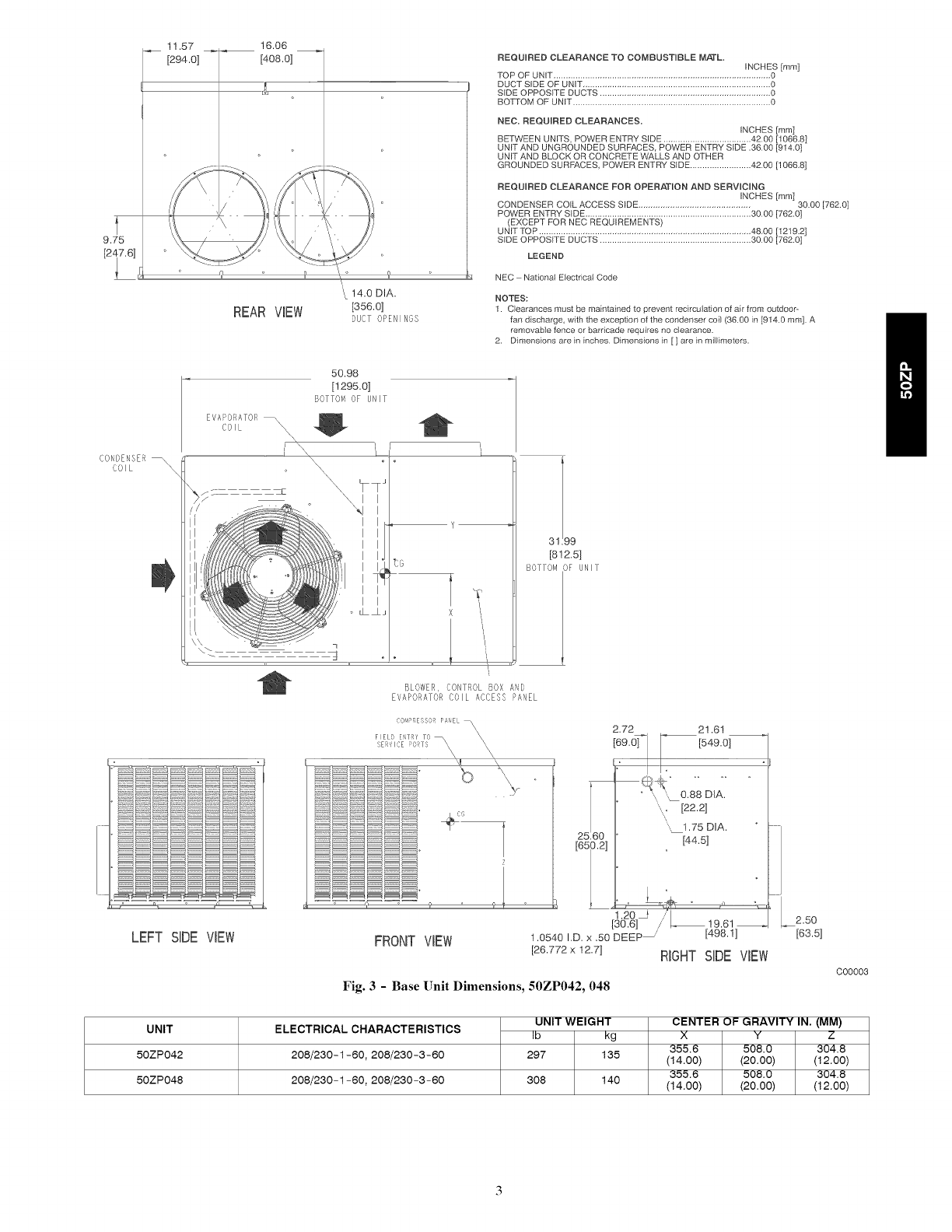
REQUIRED CLEARANCE TO COMBUSTIBLE M,,,,,,,,,,,,,,,,,,_¢L
INCHES [mini
TOP OF UNIT ......................................................................................... 0
DUCT SIDE OF UNIT ............................................................................. 0
SIDE OPPOSITE DUCTS ...................................................................... 0
BOTTOM OF UNIT ................................................................................. 0
NEe, REQUIRED CLEARANCES,
_NCHES [mini
BETWEEN UNITS POWER ENTRY SIDE .................................... 42.00 [1086.8]
UNIT AND UNGROUNDED SURFACES, POWER ENTRY SIDE .36.00 [914.0]
UNIT AND BLOCK OR CONCRETE WALLS AND OTHER
GROUNDED SURFACES, POWER ENTRY SIDE ......................... 42.00 [1068.8]
REQUIRED CLEARANCE FOR OPERATION AND SERVICING
INCHES [mini
CONDENSER COIL ACCESS SIDE .............................................. 30.00 [762.0]
POWER ENTRY SDE .................................................................... 30.00 [782.0]
(EXCEPT FOR NEC REQUIREMENTS)
UNIT TOP ....................................................................................... 48,00 [1219.2]
SIDE OPPOSITE DUCTS .............................................................. 30.00 [782.0]
LEGEND
NEC National Electrical Code
NOTES:
1. Clearances must be maintained to prevent recircu}ation of air from outdoor-
fan discharge with the exception of the condenser coi_ (38.00 in [914.0 mini. A
removable fence or barricade requires no clearance.
2. Dimensions are in inches. Dimensions in [ ] are in millimeters.
CONDENSER _
COIL
50.98
[! 295.0]
BOTTOM OK UNIT
EVAPORATOR
COIL _\ \\
\
\\
y _
tG
X
9
[8!2.5]
BOTTOMOF UNIF
BLOWER, CONTROL BOX AND
EVAPORATOR COIL ACCESS PANEL
LEFT SiDE VIEW
2.72 2! .6!
[549.0]
....,, 1.75DIA.
[44.5]
1.2_
[30.6] /
FRONTVIEW 1.0540 I.D. x .50 DEEP
[26.772 x 12.7] RIGHT
Fig. 3 -Base []nit Dimensions, 50ZP042, 048
! 9.61 2.50
[498. !] [63.5]
SIDEVIEW
C00003
UNIT
50ZP042
50ZP048
ELECTRICAL CHARACTERISTICS
208/230-1-60, 208/230-3-60
208/230-1-60, 208/230-3-60
UNIT WEIGHT
Ib kg
297 135
308 140
CENTER OI= GRAVITY IN. (MM)
XYZ
355.6 508.0 304.8
(14.00) (20.00) (12.00)
355.6 508.0 304.8
(14.00) (20.00) (12.00)
4.63 _._
[117.6]
5.44
DIMENSIONS IN []ARE IN mm
13.89
,4 [352.7]
13.89 _ _2.11
[352.8] [53.7]
t i
27.80
[706.0]
[13&3] I ,, ,
3.5o ::
REAR ViEW [8&9]
COIL ....
50.98
[1295.0]
(,TTOH ,LIE J:'ilT
CON[
,iO,IL \
\\ /,_
' "!_i"' __i
i _W,iii !
I I?
I Iii
i1!
'_;,i i
O;_IPRESS(;R SI, EL ,
FI EL) _,_T[I T',}
i ;}
34
[8C13
7.0]
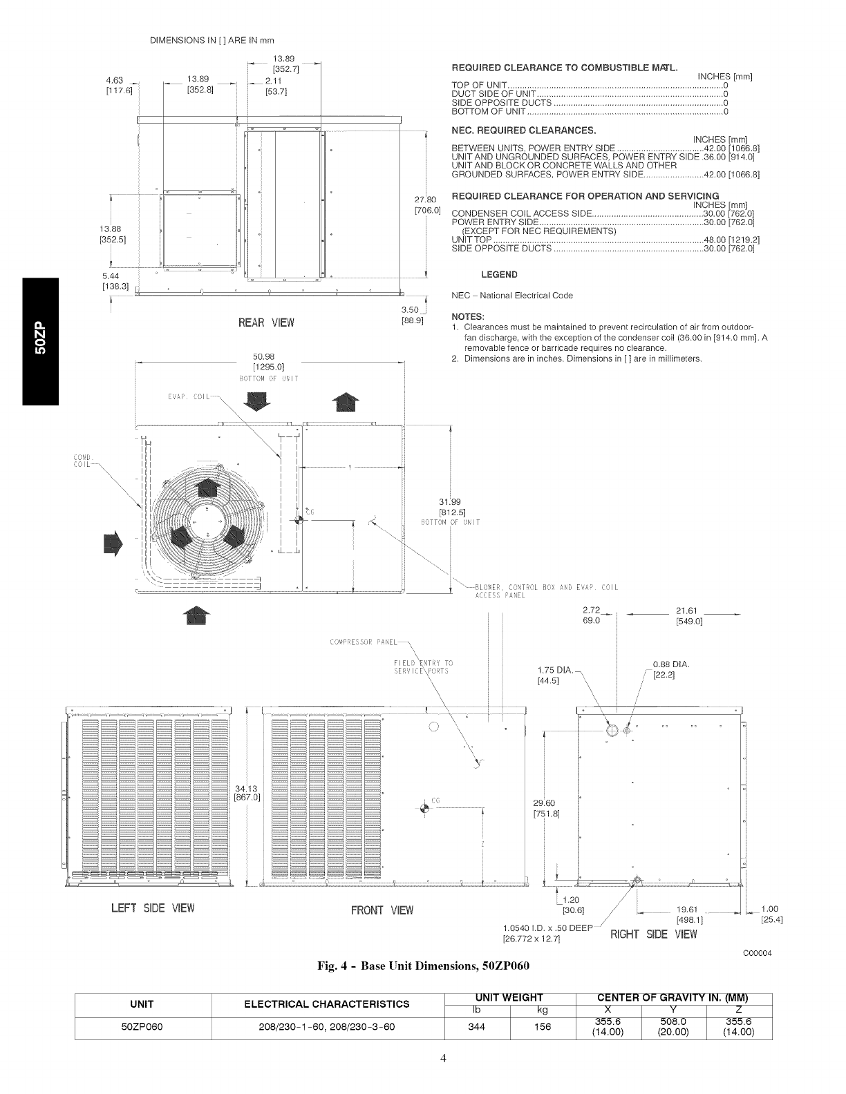
REQUIRED CLEARANCE TO COMBUSTIBLE Mfi[L.
INCHES [mm]
TOP OF UNIT ......................................................................................... 0
DUCT SIDE OF UNIT ............................................................................. 0
SIDE OPPOSITE DUCTS ...................................................................... 0
BOTTOM OF UNIT ................................................................................. 0
NEC. REQUIRED CLEARANCES.
INCHES [mm]
BETWEEN UNITS, POWER ENTRY SIDE .................................... 42.00 [1066.8]
UNIT AND UNGROUNDED SURFACES. POWER ENTRY SIDE .36.00 [914.0]
UNIT AND BLOCK OR CONCRETE WALLS AND OTHER
GROUNDED SURFACES. POWER ENTRY SIDE ......................... 4£00 [1066.8]
REQUIRED CLEARANCE FOR O£ERATION AND SERVICING
INCHES [mm]
CONDENSER COiL ACCESS SiDE .............................................. 30.00 [762.0]
POWER ENTRY SIDE .................................................................... 3O.OO [762.0]
(EXCEPT FOR NEC REQUIREMENTS)
UNIT TOP ....................................................................................... 4&00 [12!92]
SIDE OPPOSITE DUCTS .............................................................. 30.00 [762.0]
LEGEND
NEC National Electrical Code
NOTES:
1. Clearances must be maintained to prevent recirculation of air from outdoor-
fan discharge, with the exception of the condenser coil (36.00 in [914.0 mm]. A
removable fence or barricade requires no clearance.
2. Dimensions are in inches. Dimensions in [ ] are in millimeters.
31.99
[812.5]
C:TT,M (iF JI,IT
'\.
I_ - 5LOWEI, CO,?OL B,)', _1,;}, E,,£P COIL
_'CCESS £,IEL
i (_(_
2.72 21.61
69.0 [549.0]
0.88 DIA.
1.75 D1A.
[44.5] [22.2]
\\ /
\\ \/
i °
o
J
2960 }°
[751.8] [
LEFT SiDE VIEW FRONT ViEW [30,6] /" _ 19.61
/[49& 1]
1.0540 I.D. x .50 DEEP X
[26.772 x 12.7] RIGHT SIDE VIEW
Fig. 4 - Base Unit Dimensions, 50ZP060
1.0O
[25.4]
000004
UNIT
50ZP060
ELECTRICAL CHARACTERISTICS
208/230-1-60, 208/230-3-60
UNIT WEIGHT
Ib kg
344 156
CENTER OF GRAVITY IN. (MM)
XYZ
355.6 508.0 355.6
(14.00) (20.00) (14.00)
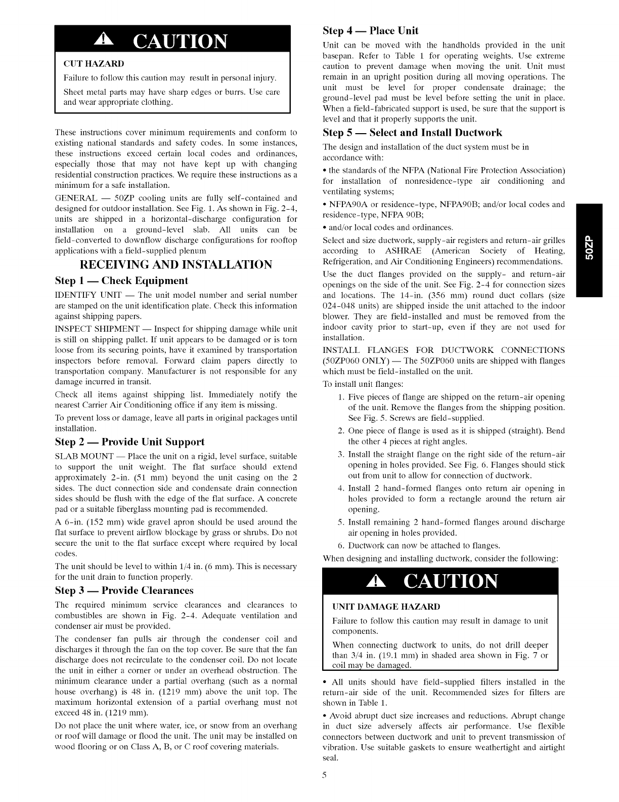
CUT HAZARD
Failure to follow this caution may result in personal injury.
Sheet metal parts may have sharp edges or burrs. Use care
and wear appropriate clothing.
These instructions cover minimum requirements and conform to
existing national standards and safety codes. In some instances,
these instructions exceed certain local codes and ordinances,
especially those that may not have kept up with changing
residential construction practices. We require these instructions as a
minimum for a safe installation.
GENERAL -- 50ZP cooling units are fully self-contained and
designed for outdoor installation. See Fig. 1. As shown in Fig. 2-4,
units are shipped in a horizontal-discharge configuration for
installation on a ground-level slab. All units can be
field-converted to downflow discharge configurations for rooftop
applications with a field-supplied plenum
RECEIVING AND INSTALLATION
Step 1 -- Check Equipment
IDENTIFY UNIT -- The unit model number and serial number
are stamped on the unit identification plate. Check this information
against shipping papers.
INSPECT SHIPMENT -- Inspect for shipping damage while unit
is still on shipping pallet. If unit appears to be damaged or is torn
loose from its securing points, have it examined by transportation
inspectors before removal. Forward claim papers directly to
transportation company. Manufacturer is not responsible for any
damage incurred in transit.
Check all items against shipping list. Immediately notify the
nearest Carrier Air Conditioning office if any item is missing.
To prevent loss or damage, leave all parts in original packages until
installation.
Step 2 -- Provide Unit Support
SLAB MOUNT -- Place the unit on a rigid, level surface, suitable
to support the unit weight. The flat surface should extend
approximately 2-in. (51 mm) beyond the unit casing on the 2
sides. The duct connection side and condensate drain connection
sides should be flush with the edge of the flat surface. A concrete
pad or a suitable fiberglass mounting pad is recommended.
A 6-in. (152 mm) wide gravel apron should be used around the
flat surface to prevent airflow blockage by grass or shrubs. Do not
secure the unit to the flat surface except where required by local
codes.
The unit should be level to within 1/4 in. (6 mm). This is necessary
for the unit drain to function properly,
Step 3 -- Provide Clearances
The required minimum service clearances and clearances to
combustibles are shown in Fig. 2-4. Adequate ventilation and
condenser air must be provided.
The condenser fan pulls air through the condenser coil and
discharges it through the fan on the top cover. Be sure that the fan
discharge does not recirculate to the condenser coil. Do not locate
the unit in either a corner or under an overhead obstruction. The
minimum clearance under apartial overhang (such as a normal
house overhang) is 48 in. (1219 mm) above the unit top. The
maximum horizontal extension of a partial overhang must not
exceed 48 in. (1219 mm).
Do not place the unit where water, ice, or snow from an overhang
or roof will damage or flood the unit. The unit may be installed on
wood flooring or on Class A, B, or C roof covering materials.
Step 4 -- Place Unit
Unit can be moved with the handholds provided in the unit
basepan. Refer to Table 1 for operating weights. Use extreme
caution to prevent damage when moving the unit. Unit must
remain in an upright position during all moving operations. The
unit must be level for proper condensate drainage; the
ground-level pad must be level before setting the unit in place.
When a field-fabricated support is used, be sure that the support is
level and that it properly supports the unit.
Step 5 -- Select and Install Ductwork
The design and installation of the duct system must be in
accordance with:
• the standards of the NFPA (National Fire Protection Association)
for installation of nonresidence-type air conditioning and
ventilating systems;
• NFPA90A or residence-type, NFPA90B; and/or local codes and
residence-type, NFPA 90B;
• and/or local codes and ordinances.
Select and size ductwork, supply-air registers and return-air grilles
according to ASHRAE (American Society of Heating,
Refrigeration, and Air Conditioning Engineers) recommendations.
Use the duct flanges provided on the supply- and return-air
openings on the side of the unit. See Fig. 2-4 for connection sizes
and locations. The 14-in. (356 mm) round duct collars (size
024-048 units) are shipped inside the unit attached to the indoor
blower. They are field-installed and must be removed from the
indoor cavity prior to start-up, even if they are not used for
installation.
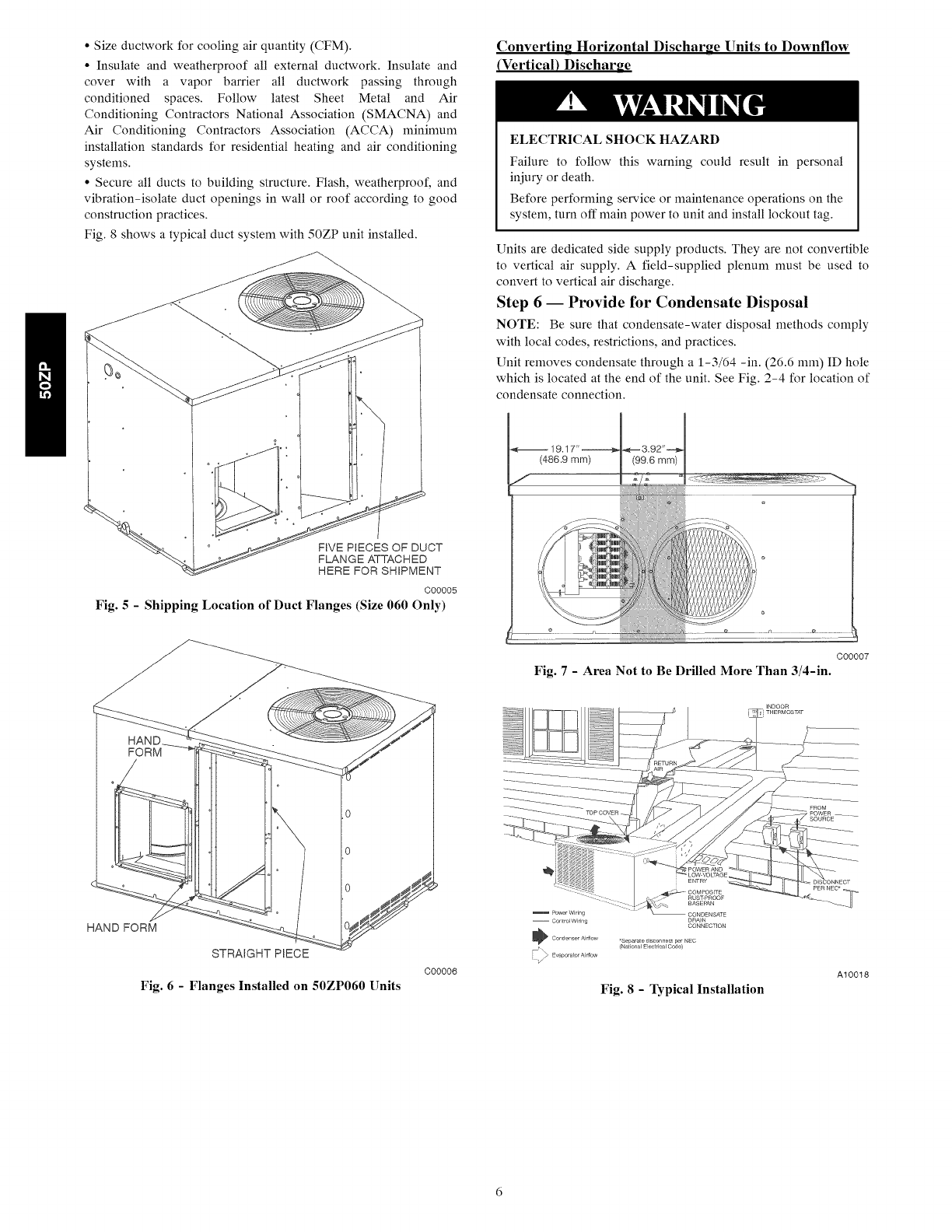
INSTALL FLANGES FOR DUCTWORK CONNECTIONS
(50ZP060 ONLY) -- The 50ZP060 units are shipped with flanges
which must be field-installed on the unit.
To install unit flanges:
1. Five pieces of flange are shipped on the return-air opening
of the unit. Remove the flanges from the shipping position.
See Fig. 5. Screws are field-supplied.
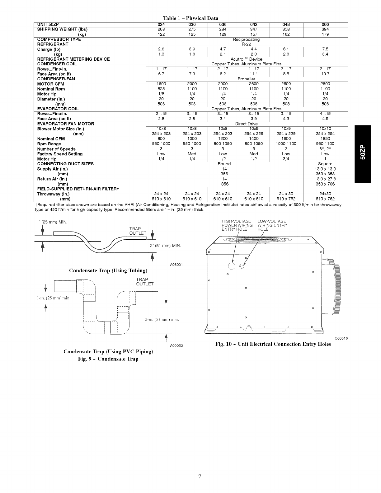
2. One piece of flange is used as it is shipped (straight). Bend
the other 4 pieces at right angles.
3. Install the straight flange on the right side of the return-air
opening in holes provided. See Fig. 6. Flanges should stick
out from unit to allow for connection of ductwork.
4. Install 2 hand-formed flanges onto return air opening in
holes provided to form a rectangle around the return air
opening.
5. Install remaining 2 hand-formed flanges around discharge
air opening in holes provided.
6. Ductwork can now be attached to flanges.
When designing and installing ductwork, consider the following:
[]NIT DAMAGE HAZARD
Failure to follow this caution may result in damage to unit
components.
When connecting ductwork to units, do not drill deeper
than 3/4 in. (19.1 mm) in shaded area shown in Fig. 7 or
coil ma}zbe damaged.
• All units should have field-supplied filters installed in the
return-air side of the unit. Recommended sizes for filters are
shown in Table 1.
• Avoid abrupt duct size increases and reductions. Abrupt change
in duct size adversely affects air performance. Use flexible
connectors between ductwork and unit to prevent transmission of
vibration. Use suitable gaskets to ensure weathertight and airtight
seal.
• Size ductwork for cooling air quantity (CFM).
• Insulate and weatherproof all external ductwork. Insulate and
cover with a vapor barrier all ductwork passing through
conditioned spaces. Follow latest Sheet Metal and Air
Conditioning Contractors National Association (SMACNA) and
Air Conditioning Contractors Association (ACCA) minimum
installation standards for residential heating and air conditioning
systems.
• Secure all ducts to building structure. Flash, weatherproof, and
vibration-isolate duct openings in wall or roof according to good
construction practices.
Fig. 8 shows a typical duct system with 50ZP unit installed.
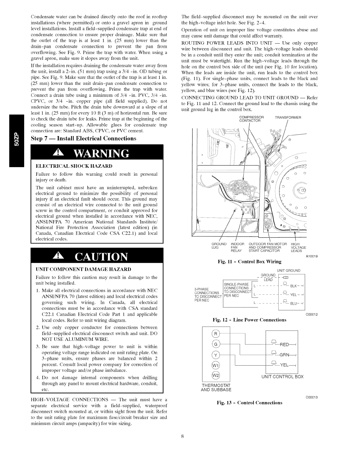
Converting Horizontal Discharge Units to Downflow
(Vertical) Discharge
ELECTRICALSHOCK HAZARD
Failure to follow this warning could result in personal
injury or death.
Before performing service or maintenance operations on the
system, turn off main power to unit and install lockout tag.
Units are dedicated side supply )roducts. They are not convertible
to vertical air supply. A field-supplied plenum must be used to
convert to vertical air discharge.
Step 6-- Provide for Condensate Disposal
NOTE: Be sure that condensate-water disposal methods comply
with local codes, restrictions, and practices.
Unit removes condensate through a 1-3/64 -in. (26.6 mm) ID hole
which is located at the end of the unit. See Fig. 2-4 for location of
condensate connection.
FIVE PIECES OF DUCT
FLANGE ATTACHED
HERE FOR SHIPMENT
C00005
Fig. 5 - Shipping Location of Duct Flanges (Size 060 Only)
C00007
Fig. 7- Area Not to Be Drilled More Than 3/4-in.
HAND FORM
STRAIGHT PIECE
Fig. 6 - Flanges Installed on 50ZP060 Units
C00006
Power Wirir g
-- Control Wiring
* Conden set Airllow *Separate di_onnec- per NEC
(National Electrical Code)
Fig. 8 - Typical Installation
DISCONNECT
pER NEC*
A10018
UNIT 50ZP
SHIPPING WEIGHT (Ibs)
(kg)
COMPRESSOR TYPE
REFRIGERANT
Charge (Ib)
(kg)
REFRIGERANT METERING DEVICE
CONDENSER COIL
Rows...Fins/in.
Face Area (sq ft)
CONDENSER-FAN
MOTOR CFM
Nominal Rpm
Motor Hp
Diameter (in.)
(mm)
EVAPORATOR COIL
Rows...Fins/in.
Face Area (sq ft)
EVAPORATOR FAN MOTOR
Blower Motor Size (in.)
(mm)
Nominal CFM
Rpm Range
Number of Speeds
Factory Speed Setting
Motor Hp
CONNECTING DUCT SIZES
Supply Air (in.)
(mm)
Return Air (in.)
(mm)
FIELD-SUPPLIED RETURN-AIR FILTERt
Throwaway (in.)
(mm)
Table I - Physical Data
024 030 036
268 275 284
122 125 129
2.8 3.9
1.3 1.8
1...17 1...17
6.7 7.9
1600 2000
825 1100
1/8 1/4
20 20
508 508
042
347
157
Reciprocating
R-22
4.7 4.4
2.1 2.0
Acutrol TM Device
Copper Tubes, Aluminum Plate Fins
2...17 1...17
6.2 11.1
Propeller
2000 2600
1100 1100
1/4 1/4
20 20
508 508
Copper Tubes, Aluminum Plate Fins
048 060
358 394
162 179
6.1 7.5
2.8 3.4
2...17 2...17
8.6 10.7
2600
1100
1/4
20
5O8
2800
1100
1/4
20
5O8
2...15 3...15 3...15 4...15
2.8 2.8 3.1 4.9
10x8 10x8
254 x 203 254 x 203
800 1000
550-1000 550-1000
3 3
Low Med
1/4 1/4
3...15 3...15
3.9 4.3
Direct Drive
10x9
254 x 229
1400
800-1050
3
Med
1/2
10x9
254 x 229
1600
1000-1100
2
Low
3/4
10x8
254 x 203
1200
800-1050
3
Low
1/2
Round
10x10
254 x 254
1850
950-1100
3*,2*
Low
1
Square
13.9 x 13.9
353 x 353
13.9 x 27.8
353 x 706
14
356
14
356
24 x 24 24 x 24 24 x 24 24 x 24 24 x 30 24x30
610 x 610 610 x 610 610 x 610 610 x 610 610 x 762 610 x 762
tRequiredfiltersizes shown are based onthe AHRI(Air Conditioning, Heating and Refrigerationlnstitute) rated airflow ata velocity of300ff/minforthrowaway
type or450ff/minforhigh capacitytype. Recommended filters are 1-in.(25 mm) thick.
1" (25 mm) MIN.
"__ t_"-'-------------d 2"(51 mm)MIN.
A08001
Condensate Trap (Using Tubing)
idn. (25 ram) mhs.
t TRAP
OUTLET
A09052
Condensate Trap (Using PVC Piping)
Fig. 9 - Condensate Trap
HIGH-VOLTAGE LOW-VOLTAGE
POWER WIRING WIRING ENTRY
ENTRY HOLE HOLE
o
jo o................j_,
Fig. 10 - Unit Electrical Connection Entry Holes
C00010
Condensate water can be drained directly onto the roof in rooftop
installations (where permitted) or onto a gravel apron in ground
level installations. Install a field-supplied condensate trap at end of
condensate connection to ensure proper drainage. Make sure that
the outlet of the trap is at least 1 in. (25 mm) lower than the
drain-pan condensate connection to prevent the pan from
overflowing. See Fig. 9. Prime the trap with water. When using a
gravel apron, make sure it slopes away from the unit.
If the installation requires draining the condensate water away from
the unit, install a 2-in. (51 mm) trap using a 3/4 -in. OD tubing or
pipe. See Fig. 9. Make sure that the outlet of the trap is at least 1 in.
(25 mm) lower than the unit drain-pan condensate connection to
prevent the pan from overflowing. Prime the trap with water.
Connect a drain tube using a minimum of 3/4 -in. PVC, 3/4 -in.
CPVC, or 3/4 -in. copper pipe (all field supplied). Do not
undersize the tube. Pitch the drain tube downward at a slope of at
least 1 in. (25 mm) for every 10 ft (3 m) of horizontal run. Be sure
to check the drain tube for leaks. Prime trap at the beginning of the
cooling season start-up. Allowable glues for condensate trap
connection are: Standard ABS, CPVC, or PVC cement.
Step 7-- Install Electrical Connections
ELECTRICALSHOCK HAZARD
Failure to follow this warning could result in personal
iniury or death.
The unit cabinet must have an uninterrupted, unbroken
electrical ground to minimize the possibility of personal
iniury if an electrical fault should occur. This ground may
consist of an electrical wire connected to the unit ground
screw in the control compartment, or conduit approved for
electrical ground when installed in accordance with NEC,
ANSI/NFPA 70 American National Standards Institute/
National Fire Protection Association (latest edition) (in
Canada, Canadian Electrical Code CSA C22.1) and local
electrical codes.
[]NIT COMPONENT DAMAGE HAZARD
Failure to follow this caution may result in damage to the
unit being installed.
1. Make all electrical connections in accordance with NEC
ANSI/NFPA 70 (latest edition) and local electrical codes
governing such wiring. In Canada, all electrical
connections must be in accordance with CSA standard
C22.1 Canadian Electrical Code Part 1 and applicable
local codes. Refer to unit wiring diagram.
2. Use only copper conductor for connections between
field-supplied electrical disconnect switch and unit. DO
NOT USE ALUMINUM WIRE.
3. Be sure that high-voltage power to unit is within
operating voltage range indicated on unit rating plate. On
3-phase units, ensure phases are balanced within 2
percent. Consult local power company for correction of
improper voltage and/or phase imbalance.
4. Do not damage internal components when drilling
through any panel to mount electrical hardware, conduit,
etc.
HIGH-VOLTAGE CONNECTIONS -- The unit must have a
separate electrical service with a field-supplied, waterproof
disconnect switch mounted at, or within sight from the unit. Refer
to the unit rating plate for maximum fuse/circuit breaker size and
minimum circuit amps (ampacity) for wire sizing.
The field-supplied disconnect may be mounted on the unit over
the high-voltage inlet hole. See Fig. 2-4.
Operation of unit on improper line voltage constitutes abuse and
may cause unit damage that could affect warranty.
ROUTING POWER LEADS INTO UNIT -- Use only copper
wire between disconnect and unit. The high-voltage leads should
be in a conduit until they enter the unit; conduit termination at the
unit must be watertight. Run the high-voltage leads through the
hole on the control box side of the unit (see Fig. 10 for location).
When the leads are inside the unit, run leads to the control box
(Fig. 11). For single-phase units, connect leads to the black and
yellow wires; for 3-phase units, connect the leads to the black,
yellow, and blue wires (see Fig. 12).
CONNECTING GROUND LEAD TO UNIT GROUND -- Refer
to Fig. 11 and 12. Connect the ground lead to the chassis using the
unit ground lug in the control box.
COMPRESSOR TRANSFORMER
CONTACTOR
@
o
o
.o
0 0
GROUND INDOOR OUTDOOR PAN MOTOR HIGH
LUG FAN AND COMPRESSOR VOLTAGE
RELAY START CAPACITOR LEADS
A10019
Fig. ll -Control Box Wiring
UNIT GROUND
GROUND[ l
r LEAD
[SINGLE-PHASE _ .......................... BLK- -/
3-PHASE |CONNECTIONS q
C00012
Fig. 12 - Line Power Connections
@
@
THERMOSTAT
AND SUBBASE
UNIT CONTROL BOX
Fig. 13 - Control Connections
C00013
ROUTING CONTROL POWER WIRES -- Form a drip-loop
with the thermostat leads before routing them into the unit. Route
the thermostat leads through grommeted hole provided in unit (see
Fig. 10) into unit control box. Connect thermostat leads to unit
control power leads as shown in Fig. 13.
Route thermostat wires through grommet providing a drip-loop at
the panel. Connect low-voltage leads to the thermostat as shown in
Fig. 13.
The unit transformer supplies 24-v power for complete system.
Transformer is factory wired for 230-v operation. If supply voltage
is 208 v, rewire transformer primary as described in the Special
Procedures for 208-v Operation section below.
SPECIAL PROCEDURES FOR 208-V OPERATION
ELECTRICALSHOCK HAZARD
Failure to follow this warning could result in personal
iniury or death.
Before performing service or maintenance operations on the
system, turn off main power to unit and install lockout tag.
1. Remove wirenut from connection of ORG wire to BLK
wire. Disconnect the ORG transformer-primary lead from
the BLK wire. Save wirenut. See unit wiring label.
2. Remove the wirenut from the terminal on the end of the
RED transformer-primary lead.
3. Save the wirenut.
4. Connect the RED lead to the BLK wire from which the
ORG lead was disconnected. Insulate with wirenut from
Step 1.
5. Using the wirenut removed from the RED lead, insulate the
loose terminal on the ORG lead.
6. Wrap the wirenuts with electrical tape so that the metal
terminals cannot be seen.
Indoor blower-motor speeds may need to be changed for 208-v
operation. Refer to Indoor Airflow and Airflow Adjustments
section.
PRE-START-UP
FIRE, EXPLOSION, ELECTRICAL SHOCK
HAZARD
Failure to follow this warning could result in personal
iniury or death and/or property damage.
1. Follow recognized safety practices and wear protective
goggles when checking or servicing refrigerant system.
2. Relieve and recover all refrigerant from system before
touching or disturbing anything inside terminal box if
refrigerant leak is suspected around compressor
terminals.
3. Never attempt to repair soldered connection while
refrigerant system is under pressure.
4. Do not use torch to remove any component. System
contains oil and refrigerant under pressure.
5. To remove a component, wear protective goggles and
proceed as follows:
a. Shut off electrical power to unit and install
lockout tag.
b. Relieve and reclaim all refrigerant from system
using both high- and low-pressure ports.
c. Cut component connecting tubing with tubing
cutter and remove component from unit.
d. Carefully unsweat remaining tubing stubs when
necessary. Oil can ignite when exposed to flame.
Use the Start-Up Checklist supplied at the end of this book and
proceed as follows to inspect and prepare the unit for initial
start-up:
1. Remove all access panels.
2. Read and follow instructions on all DANGER, WARNING,
CAUTION, and INFORMATION labels attached to, or
shipped with, unit. Make the following inspections:
a. Inspect for shipping and handling damages such as
broken lines, loose parts, disconnected wires, etc.
b. Inspect for oil at all refrigerant tubing connections and
on unit base. Detecting oil generally indicates a
refrigerant leak. Leak-test all refrigerant tubing
connections using electronic leak detector, or
liquid-soap solution. If a refrigerant leak is detected, see
following Check for Refrigerant Leaks section.
c. Inspect all field- and factory-wiring connections. Be
sure that connections are completed and tight.
d. Inspect coil fins. If damaged during shipping and
handling, carefully straighten fins with a fin comb.
3. Verify the following conditions:
a. Make sure that outdoor-fan blade is correctly positioned
in fan orifice. Top edge of blade should be 3.125 in.
down from condenser outlet grille. See Condenser Fan
section.
b. Make sure that air filter is in place.
c. Make sure that condensate drain pan and trap are filled
with water to ensure proper drainage.
d. Make sure that all tools and miscellaneous loose parts
have been removed.
START-UP
Use the Start-Up Checklist supplied at the end of this book, and
proceed as follows:
Step 1-- Check for Refrigerant Leaks
LOCATE AND REPAIR REFRIGERANT LEAKS AND
CHARGE THE UNIT AS FOLLOWS:
1. Using both high- and low-pressure ports, locate leaks and
reclaim remaining refrigerant to relieve system pressure.
2. Repair leak following accepted practices.
NOTE: Install a filter drier whenever the system has been opened
for repair.
3. Check system for leaks using an approved method.
4. Evacuate refrigerant system and reclaim refrigerant if no
additional leaks are found.
5. Charge unit with R-22 refrigerant, using a
volumetric-charging cylinder or accurate scale. Refer to
unit rating plate for required charge. Be sure to add extra
refrigerant to compensate for internal volume of
field-installed filter drier.
Step 2 -- Start-Up Cooling Section and Make
Adjustments
CHECKING COOLING CONTROL OPERATION -- Start and
check the unit for proper cooling control operation as follows:
1. Place room thermostat SYSTEM switch in OFF position.
Observe that blower motor starts when FAN switch is
placed in ON position and shuts down when FAN switch is
placed in AUTO position.
2. Place SYSTEM switch in COOL position and FAN switch
in AUTO position. Set cooling control below room
temperature. Observe that compressor, condenser fan, and
evaporator blower motors start. Observe that cooling cycle
shuts down when control setting is satisfied.
3. When using an automatic changeover room thermostat,
place both SYSTEM and FAN switches in AUTO.
positions. Observe that unit operates in Cooling mode when
temperature control is set to "call for cooling" (below room
temperature).
Step 3-- Refrigerant Charge
Amount of refrigerant charge is listed on unit nameplate (also refer
to Table 1). Refer to Carrier Refrigerant Service Techniques
Manual, Refrigerants section.
Unit panels must be in place when unit is operating during
charging procedure.
NO CHARGE -- Use standard evacuating techniques. After
evacuating system, weigh in the specified amount of refrigerant
(refer to Table 1).
LOW CHARGE COOLING -- Use Cooling Charging Charts, Fig.
14-19. Vary refrigerant until the conditions of the appropriate chart
are met. Note that charging charts are different from the type
normally used. Charts are based on charging the units to the correct
superheat for the various operating conditions. Accurate pressure
gage and temperature sensing device are required.
To measure suction pressure, perform the following:
1. Connect the pressure gage to the service port on the suction
line.
2. Mount the temperature sensing device on the suction line
and insulate it so that outdoor ambient temperature does not
affect the reading. Indoor-air cfm must be within the
normal operating range of the unit.
TO USE COOLING CHARGING CHARTS
1. Take the outdoor ambient temperature and read the suction
pressure gage.
2. Refer to appropriate chart to determine what the suction
temperature should be.
3. If suction temperature is high, add refrigerant. If suction
temperature is low, carefully recover some of the charge.
4. Recheck the suction pressure as charge is adjusted.
EXAMPLE: (Fig. 14)
Outdoor Temperature ..................... 85 ° F (29 ° C)
Suction Pressure ....................... 80 psig
Suction Temperature should be ............. 70 °F (21 ° C)
(Suction Temperature may vary _+5° F. [2.8°C])
If Chargemaster ® charging device is used, temperature and
pressure readings must be accomplished using the charging
chart.
Step 4-- Indoor Airflow and Airflow Adjust-
ments
NOTE: For cooling operation, the recommended airflow is 350
to 450 CFM for each 12,000 Btuh of rated cooling capacity.
Table 2 shows dry coil air delivery for horizontal discharge units.
Tables 3-NO TAG show pressure drops.
NOTE: Be sure that all supply- and return-air grilles are open,
free from obstructions, and adjusted properly.
ELECTRICALSHOCK HAZARD
Failure to follow this warning could result in personal
iniury or death.
Disconnect electrical power to the unit and install lockout
tag before changing blower speed.
Airflow can be changed by changing the lead connections of the
blower motor.
Units 50ZP024,036,048, and 060 blower motors are factory wired
for low speed operation. Units 50ZP030 and 042 are factory wired
for medium speed operation.
FOR 208/230-V -- The motor leads are color-coded as follows:
3-SPEED 2-SPEED
black = high speed black = high speed
blue = medium speed
red = low speed red = low speed
To change the speed of the blower motor (BM), remove the fan
motor speed leg lead from the indoor (evaporator) fan relay (IFR)
and replace with lead for desired blower motor speed. Insulate the
removed lead to avoid contact with chassis parts.
10
0 40 h3 /,o ?o 80 go
hU(T]ON LINE rEHPERATURE (°F)
I IIII II
4 I 0 I 6 21 2 7 _ 2
%UCTI ON LINE rENPERA rURE (_ (
Fig. 14 - Cooling Charging Chart, 50ZP024
C00015
", %81 i 1 3
8{331 13
Lr)t qr
Z4qo_ ....
•b U
zIC
o ID
2 7_;I 4 :,
0 4 0
X_
2 _
'!I
8050 60 ?0
5U(}T]ON LINE rEHPERATURE (°F)
I I I I I I
4 I 0 I 6 21 27
SUCT ION LINE rENPERA rURE (_ C)
KDOORTEMP
_FoO
15 46
05 41
95 35
85 29
75 24
65 18
55 13
45 7
90
I
1!/2
000017
Fig. 16 - Cooling Charging Chart, 50ZP036 Units
0 40 50 60 ?0 80 go
-'UCT]ON LINE rEHPERATURE (°F)
I IIII II
4 I 0 I @ 21 2 7 _ 2
%U(T I ON LINE rENPERA FURE (_ ()
C00016
Fig. 15 - Cooling Charging (:hart, 50ZP030 Units
) 40
I
OUTDOORTEMP
F O
2
.,,_4 105 41
_ 95 ss
_ 85 29
,,_q 75 24
_@,,__ 65 18
,,,,,,_ _ 55 13
hO (X) ?0 80 qO
",UCT]ON LINE FEHPERATURE (°F)
I I I I I I
4 I 0 I @ 21 2 7 _ 2
%U(TI ON LINE FEHPERAFURE ("()
C00018
Fig. 17 - Cooling Charging (:hart, 50ZP042 Units
11
© 40 h} [,o 7o 8© go
hU(T]ON LINE rENPERATURE (°F)
I IIII II
4 I 0 I 6 21 27 _ 2
%U(}TI ON LINE rENPERA rURE (_ (
C00019
Fig. 18 - Cooling Charging Chart, 50ZP042 Units
o 40 50 60 70 80 go
",UCT]ON LINE rENPERATURE (°F)
I IIII II
4 I 0 I 6 21 27 _ 2
%U(T I ON LINE FEMPERAFURE ("()
C00020
Fig. 19 -Cooling Charging Chart, 50ZP060 Units
Step 5-- Unit Controls
All compressors have the following internal-protection controls.
HIGH-PRESSURE RELIEF VALVE -- This valve opens when
the pressure differential between the low and high side becomes
excessive.
COMPRESSOR OVERLOAD -- This overload interrupts power
to the compressor when either the current or internal temperature
become excessive, and automatically resets when the internal
temperature drops to a safe level. This overload may require up to
60 minutes (or longer) to reset; therefore, if the internal overload is
suspected of being open, disconnect the electrical power to the unit
and check the circuit through the overload with an ohmmeter or
continuity tester.
Step 6-- Sequence of Operation
FAN OPERATION -- The FAN switch on the thermostat controls
indoor fan operation. When the FAN switch is placed in the ON
position, the IFR (indoor-fan relay) is energized through the G
terminal on the thermostat. The normally-open contacts close,
which then provide power to the indoor (evaporator) fan motor
(IFM). The IFM will run continuously when the FAN switch is set
to ON.
When the FAN switch is set to AUTO, the thermostat deenergizes
the IFR (provided there is not a call for cooling). The contacts open
and the IFM is deenergized. The IFM will be energized only when
there is a call for cooling.
NOTE: 50ZP030 and 060 units are equipped with a time-delay
relay. On these units, the indoor fan remains on for 30 seconds
after G or Y is deenergized.
COOLING -- On a call for cooling, the compressor contactor (C)
and the IFR are energized through the Y and G terminals of the
thermostat. On units with a compressor time-delay relay, there is a
5-minute (_+ 45 sec) delay between compressor starts. Energizing
the compressor contactor supplies power to the compressor and the
outdoor (condenser) fan motor (OFM). Energizing the IFR
provides power to the IFM.
When the need for cooling has been satisfied, the OFM,
compressor, and IFM (FAN on AUTO) are deenergized. If the unit
is equipped with a 30-second delay, the indoor fan will remain
energized for 30 seconds after the compressor is deenergized (030
and 060 units only).
MAINTENANCE
To ensure continuing high performance, and to reduce the
possibility of premature equipment failure, periodic maintenance
must be performed on this equipment. This cooling unit should be
inspected at least once each year by a qualified service person. To
troubleshoot cooling of units, refer to Troubleshooting chart in
back of book.
NOTE: TO EQUIPMENT OWNER: Consult your local dealer
about the availability of a maintenance contract.
PERSONAL INJURY AND UNIT DAMAGE
HAZARD
Failure to follow this warning could result in personal
iniury or death and possible unit component damage.
The ability to properly perform maintenance on this
equipment requires certain expertise, mechanical skills,
tools and equipment. If you do not possess these, do not
attempt to perform any maintenance on this equipment,
other than those procedures recommended in the Owner's
Manual.
The minimum maintenance requirements for this equipment are as
follows:
1. Inspect air filter(s) each month. Clean or replace when
necessary.
2. Inspect indoor coil, outdoor coil, drain pan, and condensate
drain each cooling season for cleanliness. Clean when
necessary.
3. Inspect blower motor and wheel for cleanliness each
cooling season. Clean when necessary.
4. Check electrical connections for tightness and controls for
proper operation each cooling season. Service when
necessary.
5. Check the drain channel in the top cover periodically for
blockage (leaves, insects). Clean as needed.
12

ELECTRICALSHOCKHAZARD
Failureto follow these warnings could result in personal
injury or death:
1. Turn off electrical power and install lockout tag to the
unit before performing any maintenance or service on
this unit.
2. Use extreme caution when removing panels and parts.
3. Never place anything combustible either on or in contact
with the unit.
Step 1-- Air Filter
IMPORTANT: Never operate the unit without a suitable air filter
in the return-air duct system. Always replace the filter with the
same dimensional size and type as originally installed. See Table 1
for recommended filter sizes.
Inspect air filter(s) at least once each month and replace
(throwaway-type) or clean (cleanable-type) at least twice during
each cooling season or whenever the filters become clogged with
dust and lint.
Replace filters with the same dimensional size and type as
originally provided, when necessary.
Step 2 -- Unit Top Removal (Condenser-Coil
Side)
NOTE: When performing maintenance or service procedures that
require removal of the unit top, be sure to perform all of the routine
maintenance procedures that require top removal, including coil
inspection and cleaning, and condensate drain pan inspection and
cleaning.
ELECTRICALSHOCK HAZARD
Failure to follow this warning could result in personal
injury or death.
Disconnect electrical power, and install lockout tag to the
unit before removing top.
Only qualified service personnel should perform maintenance and
service procedures that require unit top removal.
Refer to the following top removal procedures:
1. Remove 7 screws on unit top cover surface. (Save all
screws.)
2. Remove 2 screws on unit top cover flange. (Save all
screws.)
3. Lift top from unit carefully. Set top on edge and make sure
that top is supported by unit side that is opposite duct (or
plenum) side.
4. Carefully replace and secure unit top to unit, using screws
removed in Steps 1 and 2, when maintenance and/or service
procedures are completed.
Step 3-- Evaporator Blower and Motor
For longer life, operating economy, and continuing efficiency,
clean accumulated dirt and grease from the blower wheel and
motor annually.
ELECTRICALSHOCK HAZARD
Failure to follow this warning could result in personal
injury or death.
Disconnect electrical power, and install lockout tag to the
unit before cleaning and lubricating the blower motor and
wheel.
To clean the blower wheel:
1. Access the blower assembly as follows:
a. Remove top access panel.
b. Remove 3 screws that hold blower orifice ring to blower
housing. Save screws.
c. Loosen setscrew(s) which secure wheel to motor shaft.
2. Remove and clean blower wheel as follows:
a. Lift wheel from housing. When handling and/or
cleaning blower wheel, be sure not to disturb balance
weights (clips) on blower wheel vanes.
b. Remove caked-on dirt from wheel and housing with a
brush. Remove lint and/or dirt accumulations from
wheel and housing with vacuum cleaner, using a soft
brush attachment. Remove grease and oil with a mild
solvent.
c. Reassemble blower into housing. Place upper orifice
ring on blower to judge location of the blower wheel.
Blower wheel should be approximately 0.2-in. (5 mm)
below bottom of orifice ring when centered correctly.
Be sure setscrews are tightened on motor and are not on
round part of shaft.
d. Set upper orifice ring in place with 3 screws removed in
step 1.
e. Replace top access panel.
Step 4-- Condenser Coil, Evaporator Coil, and
Condensate Drain Pan
Inspect the condenser coil, evaporator coil, and condensate drain
pan at least once each year. Proper inspection and cleaning requires
the removal of the unit top. See Unit Top Removal section above.
The coils are easily cleaned when dry; therefore, inspect and clean
the coils either before or after each cooling season. Remove all
obstructions (including weeds and shrubs) that interfere with the
airflow through the condenser coil. Straighten bent fins with a fin
comb. If coated with dirt or lint, clean the coils with a vacuum
cleaner, using a soft brush attachment. Be careful not to bend the
fins. If coated with oil or grease, clean the coils with a mild
detergent-and-water solution. Rinse coils with clear water, using a
garden hose. Be careful not to splash water on motors, insulation,
wiring, or air filter(s). For best results, spray condenser-coil fins
from inside to outside the unit. On units with an outer and inner
condenser coil, be sure to clean between the coils. Be sure to flush
all dirt and debris from the unit base.
Inspect the drain pan and condensate drain line when inspecting
the coils. Clean the drain pan and condensate drain by removing all
13
foreignmatterfromthepan.Flushthepananddraintubewith
clearwater.Donotsplashwaterontheinsulation,motor,wiring,or
airfilter(s).Ifthedraintubeisrestricted,clearitwitha"plumbers
snake" or similar probe device. Ensure that the auxiliary drain port
above the drain tube is also clear.
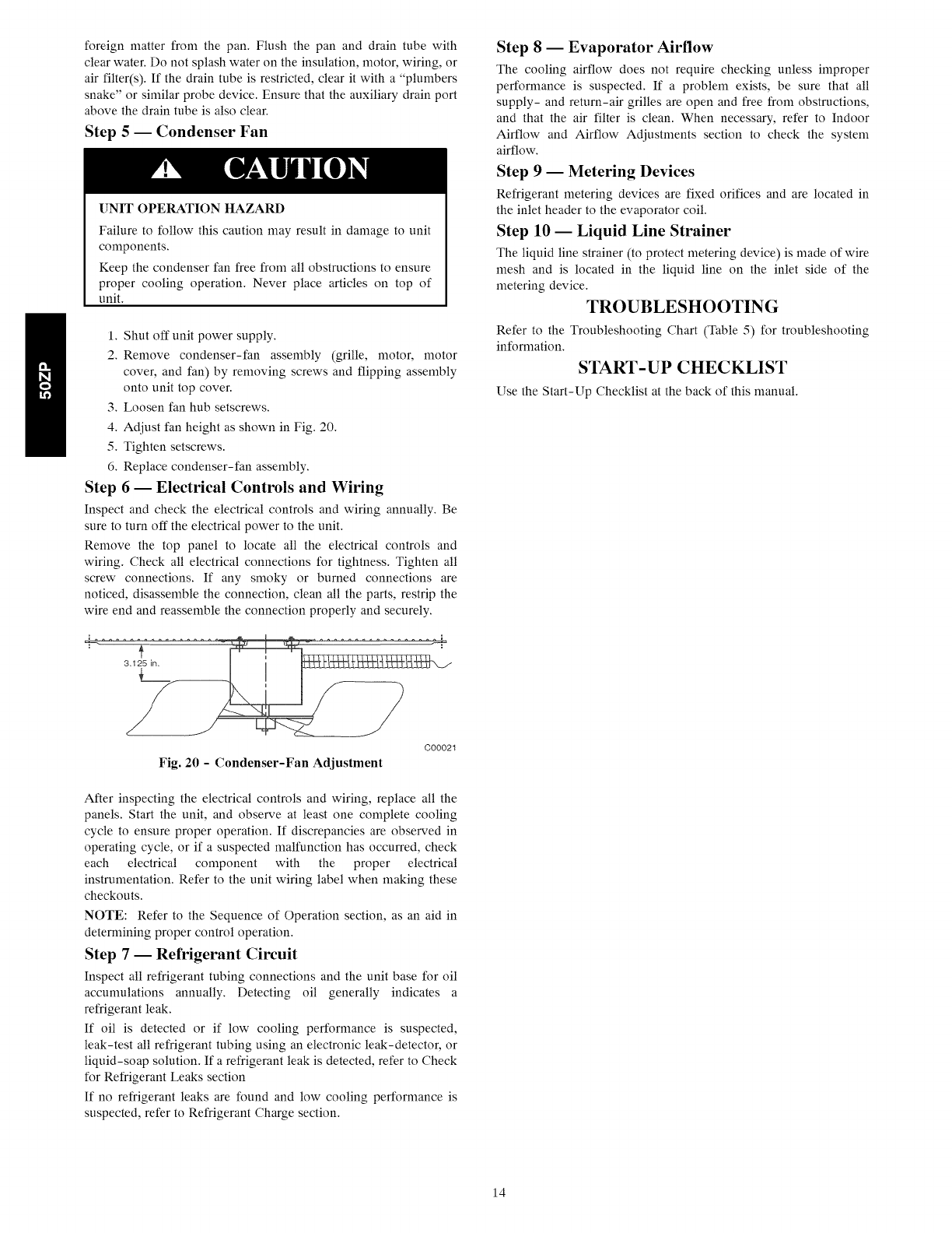
Step 5-- Condenser Fan
UNIT OPERATION HAZARD
Failure to follow this caution may result in damage to unit
components.
Keep the condenser fan free from all obstructions to ensure
proper cooling operation. Never place articles on top of
unit.
1. Shut off unit power supply.
2. Remove condenser-fan assembly (grille, motor, motor
cover, and fan) by removing screws and flipping assembly
onto unit top cover.
3. Loosen fan hub setscrews.
4. Adjust fan height as shown in Fig. 20.
5. Tighten setscrews.
6. Replace condenser-fan assembly.
Step 6 -- Electrical Controls and Wiring
Inspect and check the electrical controls and wiring annually. Be
sure to turn off the electrical power to the unit.
Remove the top panel to locate all the electrical controls and
wiring. Check all electrical connections for tightness. Tighten all
screw connections. If any smoky or burned connections are
noticed, disassemble the connection, clean all the parts, restrip the
wire end and reassemble the connection properly and securely.
Step 8 -- Evaporator Airflow
The cooling airflow does not require checking unless improper
performance is suspected. If a problem exists, be sure that all
supply- and return-air grilles are open and free from obstructions,
and that the air filter is clean. When necessary, refer to Indoor
Airflow and Airflow Adjustments section to check the system
airflow.
Step 9 -- Metering Devices
Refrigerant metering devices are fixed orifices and are located in
the inlet header to the evaporator coil.
Step 10 -- Liquid Line Strainer
The liquid line strainer (to protect metering device) is made of wire
mesh and is located in the liquid line on the inlet side of the
metering device.
TROUBLESHOOTING
Refer to the Troubleshooting Chart (Table 5) for troubleshooting
information.
START-UP CHECKLIST
Use the Start-Up Checklist at the back of this manual.
Fig. 20 - Condenser-Fan Adjustment
C00021
After inspecting the electrical controls and wiring, replace all the
panels. Start the unit, and observe at least one complete cooling
cycle to ensure proper operation. If discrepancies are observed in
operating cycle, or if a suspected malfunction has occurred, check
each electrical component with the proper electrical
instrumentation. Refer to the unit wiring label when making these
checkouts.
NOTE: Refer to the Sequence of Operation section, as an aid in
determining proper control operation.
Step 7 -- Refrigerant Circuit
Inspect all refrigerant tubing connections and the unit base for oil
accunmlations annually. Detecting oil generally indicates a
refrigerant leak.
If oil is detected or if low cooling performance is suspected,
leak-test all refrigerant tubing using an electronic leak-detector, or
liquid-soap solution. If a refrigerant leak is detected, refer to Check
for Refrigerant Leaks section
If no refrigerant leaks are found and low cooling performance is
suspected, refer to Refrigerant Charge section.
14
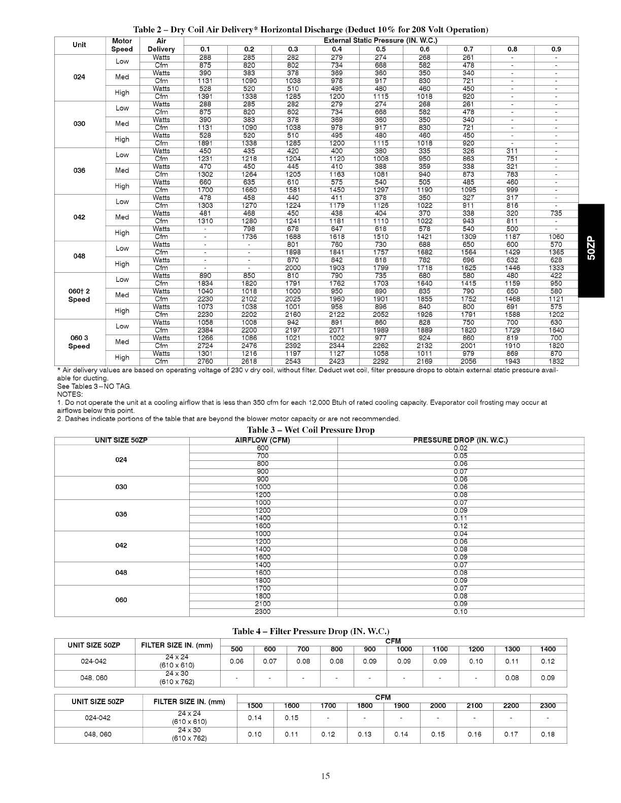
Table2-Dry Coil Air Delivery* Horizontal Discharge (Deduct 10%for 208 Volt Operation)
Unit External Static Pressure (IN.
0.1 0.2 0.4 0.8 0.9
288 285 279
875 820 734
390 383 369
024 1131 1090 978
528 520 495
1391 1338 1200
288 285 279
875 820 734
390 383 369
030 1131 1090 978
528 520 495
1891 1338 1200
450 435 400
1231 1218 1120
470 450 410
036 1302 1264 1163
660 635
1700 1660
478 458
1303 1270
481 468
042 1310 1280
798
1736
048
Motor Air
Speed Delivery
Watts
Low Cfm
Watts
Med Cfm
Watts
High Cfm
Watts
Low Cfm
Watts
Med Cfm
Watts
High Cfm
Watts
Low Cfm
Watts
Med Cfm
Watts
High Cfm
Watts
Low Cfm
Watts
Med Cfm
Watts
High Cfm
Watts
Low Cfm
Watts
High Cfm
Watts
Low Cfm
060t 2 Med Watts
Speed Cfm
Watts
High Cfm
Watts
Low Cfm
060 3 Watts
Med
Speed Cfm
Watts
High Cfm
89O
1834
1040
2230
1073
2230
1058
2384
1266
2724
1301
2760
85O
1820
1018
2102
1038
2202
1008
2200
1086
2476
1216
2618
0.3
282
8O2
378
1038
510
1285
282
8O2
378
1038
510
1285
420
1204
445
1205
610
1581
440
1224
450
1241
678
1688
801
1898
870
2000
810
1791
1000
2025
1001
2160
942
2197
1021
2392
1197
2543
575
1450
411
1179
438
1181
647
1618
76O
1841
842
1903
790
1762
950
1960
958
2122
891
2071
1002
2344
1127
2423
W.C.)
0.5 0.6
274 268
668 582
360 350
917 830
480 460
1115 1018
274 268
668 582
360 350
917 830
480 460
1115 1018
380 335
1008 950
388 359
1081 940
540 505
1297 1190
378 350
1126 1022
404 370
1110 1022
618 578
1510 1421
730 688
1757 1682
818 782
1799 1718
735 680
1703 1640
890 835
1901 1855
896 840
2052 1926
860 828
1989 1889
977 924
2262 2132
1058 1011
2292 2169
0.7
261
478
34O
721
45O
92O
261
478
34O
721
45O
92O
326
863
338
873
485
1095
327
911
338
943
540
1309
650
1564
696
1625
580
1415
790
1752
800
1791
750
1820
860
2001
979
2056
311
751
321
783
46O
999
317
816
32O
811
5OO
1187
6OO
1429
632
1446
480
1159
650
1468
691
1588
700
1729
819
1910
869
1943
735
150600
163685
950
580
1121
575
1202
630
1840
700
1820
870
1832
* Air delivery values are based on operating voltage of 230 v dry coil, without filter. Deduct wet coil, filter pressure drops to obtain external static pressure avail-
able for ducting,
See Tables 3-NO TAG.
NOTES:
1. Do not operate the unit at a cooling airflow that is less than 350 cfm for each 12,000 Btuh of rated cooling capacity. Evaporator coil frosting may occur at
airflows below this point.
2. Dashes indicate portions of the table that are beyond the blower motor capacity or are not recommended.
Table 3 - Wet Coil Pressure Drop
UNIT SIZE 50ZP AIRFLOW (CFM)
024
030
036
042
048
6OO
7OO
8OO
9OO
9OO
1000
1200
1000
1200
1400
1600
1000
1200
1400
1600
1400
1600
1800
1700
1800
2100
2300
PRESSURE DROP (IN. W.C.)
0.02
0.05
0.06
0.07
0.06
0.06
0.08
0.07
0.09
0.11
0.12
0.04
0.06
0.08
0.09
0.07
0.08
0.09
0.07
0.08
0.09
0.10
060
UNIT SIZE 50ZP
024-042
048,060
UNIT SIZE 50ZP
024-042
FILTER SIZE IN. (mm)
24 x 24
(810 x 610)
24 x 30
(610 x 762)
Table 4 - Filter Pressure Drop (IN. W.C.)
CFM
500 600 700 800 900 1000
0.06 0.07 0.08 0.08 0.09 0.09
1100 1200 1300 1400
0.09 0.10 0.11 0.12
0.08
CFM
FILTER SIZE IN. (mm)
24 x 24
(810 x 610)
24 x 30
(610 x 762)
0.09
1500 1600 1700 1800 1900 2000 2100 2200 2300
0.14 0.15
048,060 0.10 0.11 0.12 0.13 0.14 0.15 0.16 0.17 0.18
15
NAXIMU_ WIRE
SIZE 2 AWG
I
TNERNOSTATSUB-BASE
COI_MON
(SEE NOTE_D)
ear SPLICE
BOX
COMPONENTARRANGEMENT
_KEL_ OFN J
DR_
EONIP GNO
==L-.
_._{030,03G_04R A $60)
CAPe
RRN D OPM CAP1
IP_ CAP
{ODa D 048)
OR IPR;D
LEGEND
FIELO SPLICE C CONFAC TOR,CO_PRESSOR
CAP CAPACITOR
CONP COMPRESSOR ROTOR
_ARNEO WIRE
EOUIP EONIPHENT
TERMINAL (NARNED) FL FNSE LINK
OTENNINNL (NN_ANNES) FR FUSE
GNS GROUND
TERNINAL BLOCK NR HEATER RELAY {STRIP NEAT)
SPLICE IP_ INDOOR FAN ROTOR
SPLICE {_ARKED) IPN INDOOR FAN RELAY
[P INTERNAL PROTECTOR
FACTORY _IRIRG 0fN OUTDOOR FAR _OTOR
OT OUADRUPL Z TERmiNAL
FIELD CONTROL _IRIRG SB SLO_ 8LO_ FUSE
FIELS PO_ER _[RING ST START TNEN_STSR
TB TERMINAL DLOCK
_ACCESSORY OR OPTIONAL _IRING TDR T[_E DELAY RELAY
TO INDICATE CO,NON TH THERmOSTAT-HEATING
POTENTIAL ONLY: TRAM TRARSFORf_ER
NOT TO REPRESENT _IRING
NOTES
l. IP ANY OF TIE ORIGINAL _IRE FURNISHED
RUST BE REPLACED, IT HURT BE REPLACED
• ITR TYPE 90=G _IRE OR ITS EOUIVALENT.
£.SEE PRICE PAGES FOR TNERNOSTAT
ANO SRBBASE PART RUNNERS. FAN SEOUENCE FOR TDR
3. SET NEAT ANTICIPATOR AT .R rTOR
,_.USE ?D_C COPPER CONDUCTORS ONLY. j)% ,31
S._)/_D IS CONNECTED ONLY IF EXTERNAL
HEATING SOURCE IS USES. _ 0TT_3O
@ 0
NERGIZED OE -ENERGIDEO
50ZP500656 A
A10093
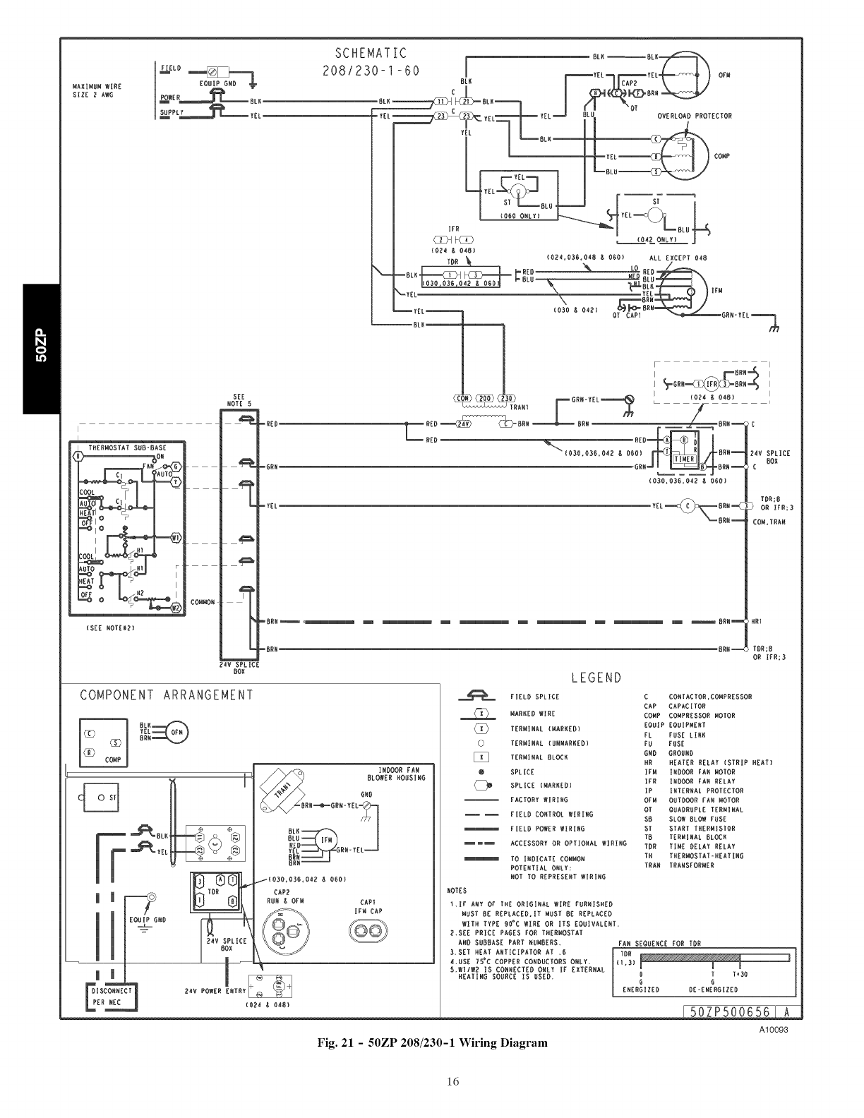
Fig. 21 -50ZP 208/230-1 Wiring Diagram
16
MAXIMUM WIRE
BIZE 2 AWB
-_
P_L=== _======_ TEL
B_ _IIt_BL U __
(_E NOTE_2)
COMMON,
SCHEMATIC
208/230-3-60
BLK_
L_---_)o,,
COMP
IFR
_ OVERLOAD PROTECTOR
BLU (O_IB) (036,04B I_ OBOE ALL EXCEPT O4B
---:LL--l
I I ', =_, I
ANI FGRN-YEL_ //
-i:::=-_--__.=--_o= -ooo_ i.=-i_
_',O=B.O,=BOBO,_I kBR°--kV=RL=E
o=Jl _=o=--Ic B°=
<o_> |
........
......... oX], oo
IfR_3
LEGEND
COMPONENT ARRANGEMENT
CO4B)
FIELD SPLICE C CONTACTOR,COHPREBSOR
CAP CAPACITOR
_X) HARKED NINE CONP CONPBEBBOR ROTOR
TERNINAL {BARKED) EQUIP EQUIPMENT
FL FUBE LINK
0TERNINAL {UNIARKEB) FU FoBl
BIB GROUND
TERMINAL BLOCK I_R _ATER RBLAY CBTRIP _AT)
@ 5PLIOE )FN INDOOR FAN ROTOR
SPLICE (HAIIKEB) IFR INDOOR FAN BELAY
IP INTERNAL PROTECTOR
FACTORY WIRING OFN OUTDOOR FAN ROTOR
OT OUADRUPLE TERNIWAL
FIELD CONTROL WIRING SB BLOW BLOW FUBE
FIELD POWBR WIRING TB TERMINAL BLOCK
TOR TINE DELAY RELAY
lllllllllmmllllllllmACCEBBOIIY OR OPTIONAL WIRING TH THBRHOBTAT=HBATING
TO INDICATE CONNOB TRAN TRANBFORNER
POTENTIAL ONLY=
NOT TO REPREBENT WIRING
NOTEB
l. IF All Of TIIE ORIGINAL WIRE FURNI_B
MUST BE REPLACED, IT MUST BE REPLACED
WITH TYPE 9O'C WIRE OR ITS EOUIVALENT,
2.BEE PRICE PAGEB FOR TIIEBMOBTAT
AND BUBBASI_ PART NUMBERB,
3.USE 7B_C COPPER CONBUCTORB ONLY.
_.Wl/W? IS CO_NECTED O_LY IF
[XT[RNAL H[ATING SOORC[ IS US[D.
FANBEOOENCEFOBTOR
TOR
_I,3) I I I
OTT_3O
B O
ENIRGIZEB BE=ENERGIZED
50/P50066 A
A10094
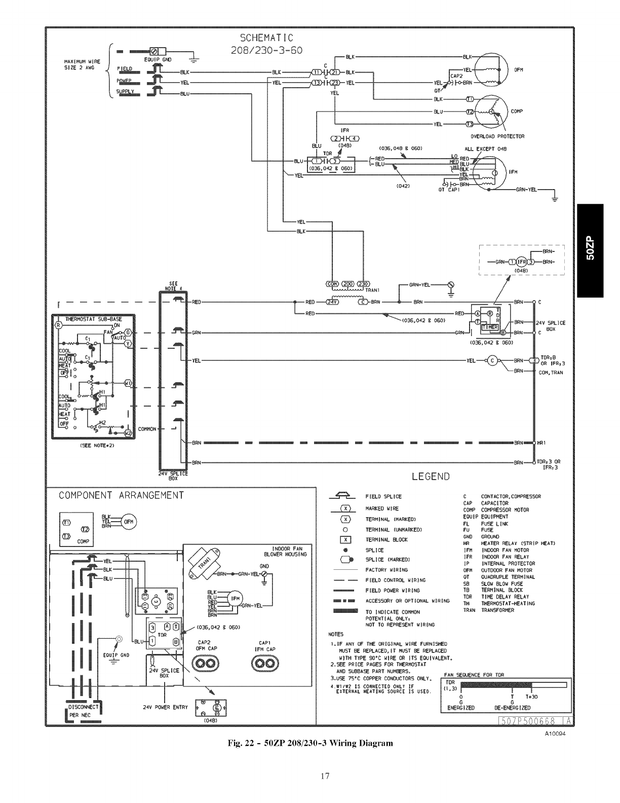
Fig. 22 -50ZP 208/230-3 Wiring Diagram
17
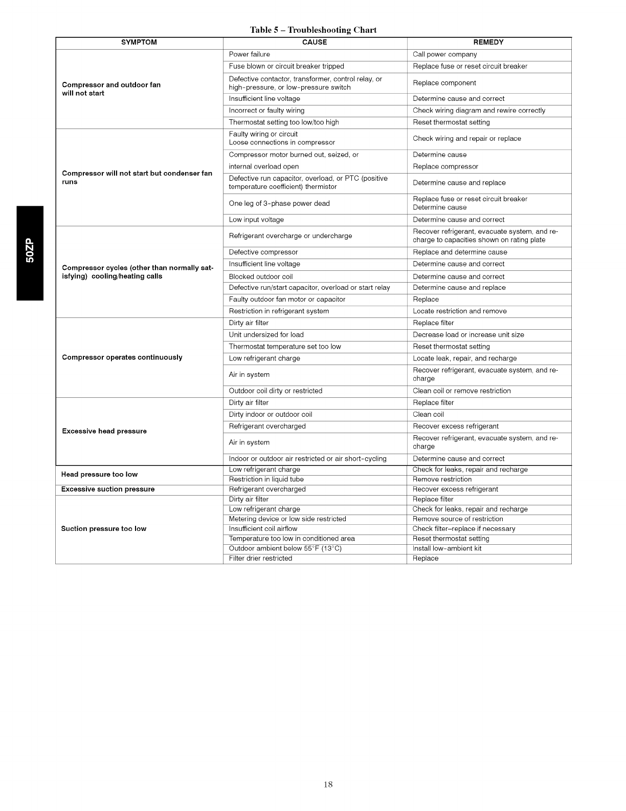
SYMPTOM
Compressor and outdoor fan
will not start
Compressor will not start but condenser fan
runs
Compressor cycles (other than normally sat-
isfying) cooling/heating calls
Compressor operates continuously
Excessive head pressure
Head pressure too low
Excessive suction pressure
Suction pressure too low
Table 5 - Troubleshooting Chart
CAUSE
Power failure
Fuse blown or circuit breaker tripped
Defective contactor, transformer, control relay, or
high-pressure, or low-pressure switch
Insufficient line voltage
Incorrect or faulty wiring
Thermostat setting too low/too high
Faulty wiring or circuit
Loose connections in compressor
Compressor motor burned out, seized, or
internal overload open
Defective run capacitor, overload, or PTC (positive
temperature coefficient) thermistor
One leg of 3-phase power dead
Low input voltage
Refrigerant overcharge or undercharge
Defective compressor
Insufficient line voltage
Blocked outdoor coil
Defective run/start capacitor, overload or start relay
Faulty outdoor fan motor or capacitor
Restriction in refrigerant system
Dirty air filter
Unit undersized for load
Thermostat temperature set too low
Low refrigerant charge
Air in system
Outdoor coil dirty or restricted
Dirty air filter
Dirty indoor or outdoor coil
Refrigerant overcharged
Air in system
Indoor or outdoor air restricted or air short-cycling
Low refrigerant charge
Restriction in liquid tube
Refrigerant overcharged
Dirty air filter
Low refrigerant charge
Metering device or low side restricted
Insufficient coil airflow
Temperature too low in conditioned area
Outdoor ambient below 55°F (13°C)
Filter drier restricted
REMEDY
Call power company
Replace fuse or reset circuit breaker
Replace component
Determine cause and correct
Check wiring diagram and rewire correctly
Reset thermostat setting
Check wiring and repair or replace
Determine cause
Replace compressor
Determine cause and replace
Replace fuse or reset circuit breaker
Determine cause
Determine cause and correct
Recover refrigerant, evacuate system, and re-
charge to capacities shown on rating plate
Replace and determine cause
Determine cause and correct
Determine cause and correct
Determine cause and replace
Replace
Locate restriction and remove
Replace filter
Decrease load or increase unit size
Reset thermostat setting
Locate leak, repair, and recharge
Recover refrigerant, evacuate system, and re-
charge
Clean coil or remove restriction
Replace filter
Clean coil
Recover excess refrigerant
Recover refrigerant, evacuate system, and re-
charge
Determine cause and correct
Check for leaks, repair and recharge
Remove restriction
Recover excess refrigerant
Replace filter
Check for leaks, repair and recharge
Remove source of restriction
Check filter-replace if necessary
Reset thermostat setting
Install low-ambient kit
Replace
18
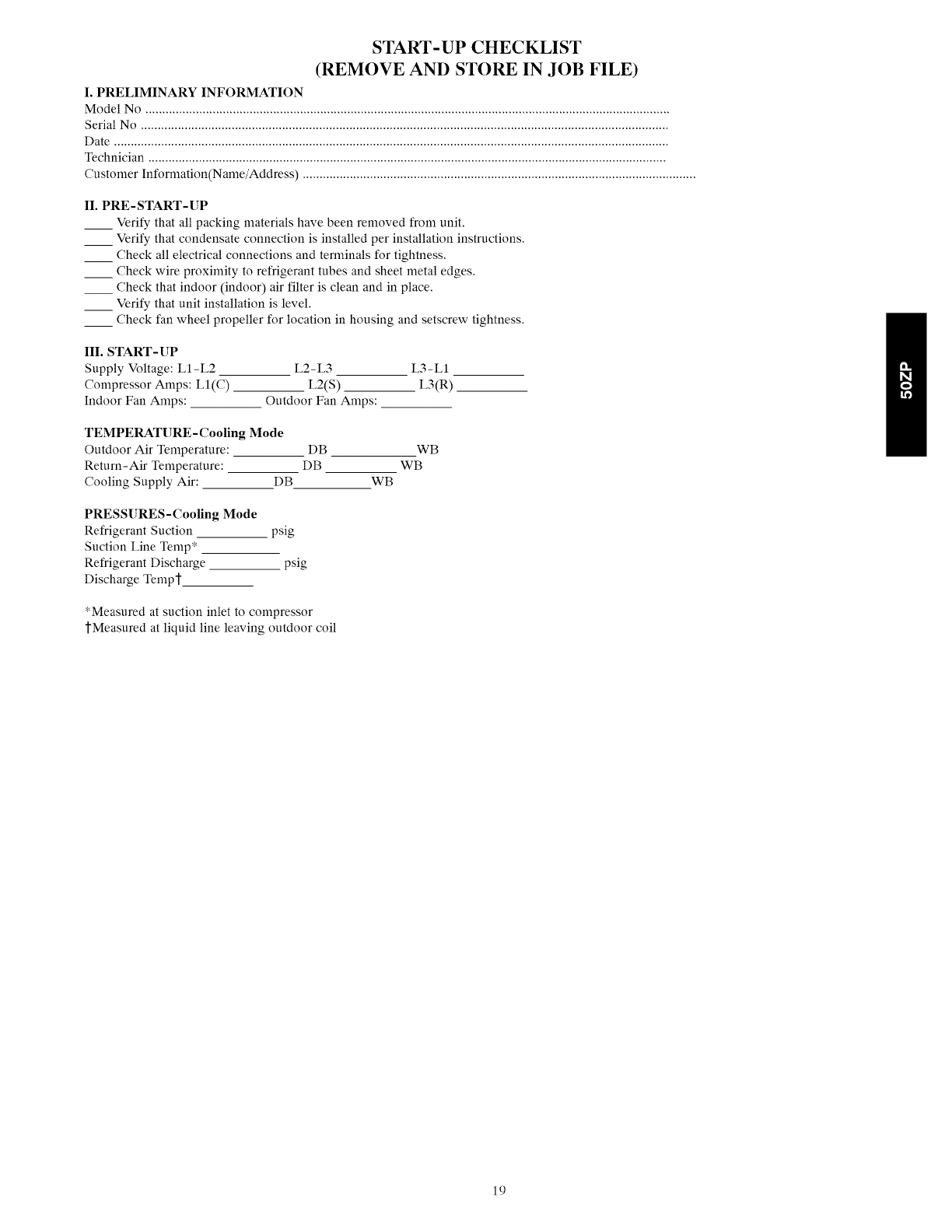
START-UP CHECKLIST
(REMOVE AND STORE IN JOB FILE)
I. PRELIMINARY INFORMATION
Model No ............................................................................................................................................................
Serial No .............................................................................................................................................................
Date .....................................................................................................................................................................
Technician ..........................................................................................................................................................
Customer Information(Name/Address) .....................................................................................................................
II. PRE-START-UP
__ Verify that all packing materials have been removed from unit.
__ Verify that condensate connection is installed per installation instructions.
__ Check all electrical connections and terminals for tightness.
__ Check wire proximity to refrigerant tubes and sheet metal edges.
__ Check that indoor (indoor) air filter is clean and in place.
__ Verify that unit installation is level.
__ Check fan wheel propeller for location in housing and setscrew tightness.
IlL START-UP
Supply Voltage: L1-L2 L2-L3 L3-L1
Compressor Amps: LI(C) L2(S) L3(R)
Indoor Fan Amps: Outdoor Fan Amps:
TEMPERATURE-Cooling Mode
Outdoor Air Temperature:
Return-Air Temperature:
Cooling Supply Air: DB
DB WB
DB WB
WB
PRESSURES-Cooling Mode
Refrigerant Suction psig
Suction Line Temp*
Refrigerant Discharge psig
Discharge Temp]-
*Measured at suction inlet to compressor
]-Measured at liquid line leaving outdoor coil
19
Copyright 2010 Carrier Corp. • 7310 W. Morris St. • Indianapolis, IN 46231 Printed in U.S.A. Edition Date: 02/10
Manufacturer reserves the right to change, at any time, specification8 and design8 without notice and without obligations,
Catalog No: 50ZP-06SI
Replaces: 50ZP-4SI
2O
