Carrier 58CVA110 10020 User Manual FURNACE Manuals And Guides 1209611L
User Manual: Carrier 58CVA110---10020 58CVA110---10020 CARRIER FURNACE - Manuals and Guides View the owners manual for your CARRIER FURNACE #58CVA11010020. Home:Heating & Cooling Parts:Carrier Parts:Carrier FURNACE Manual
Open the PDF directly: View PDF ![]() .
.
Page Count: 34
Installation Instructions
NOTE: Read the entire instruction manual before starting the
installation.
SAFETY CONSIDERATION
FIRE, EXPLOSION, ELECTRICAL SHOCK, AND
CARBON MONOXIDE POISONING HAZARD
Failure to follow this warning could result in personal
injury or death.
This conversion kit shall be installed by a qualified service
agency in accordance with the manufacturer's instructions
and all applicable codes and requirements of the authority
having jurisdiction. If the information in these instructions
is not followed exactly, a fire, explosion, or production of
carbon monoxide could result causing property damage,
personal injury, or loss of life. The qualified service agency
is responsible for the proper installation of this furnace with
this kit. The installation is not proper and complete until the
operation of the converted appliance is checked as specified
in the manufacturer's instructions supplied with the kit.
LE FEU, L'EXPLOSION, CHOC ELECTRIQUE,
ET MONOXYDE DE CARBONE
EMPOISONNER
Cette trousse de conversion doit 0tre install0e par un servie
d'entretien qualifiO, selon les instructions du fabricant et
selon routes les exigences et tousles codes pertinents de
l'autoritO compOtente. Assurezvous de bien suivre les
instructions dans cette notice pour rOduire au minimum le
risque d'incendie, d'explosion ou la production de
monoxyde de carbone pouvant causer des dommages
mat0riels, de blessure ou la mort. Le service d'entretien
qualifiO est responsable de l'installation de cette trousse.
L'installation n'est pas adOquate ni complOte rant que le bon
fonctionnement de l'appereil converti n'a pas Or0 vOrfiO
selon les instructions du fabricant fornies avec la trousse.
Installing and servicing heating equipment can be hazardous due
to gas and electrical components. Only trained and qualified
personnel should install, repair, or service heating equipment.
Untrained personnel can perform basic maintenance functions
such as cleaning and replacing air filters. Trained service
personnel must perform all other operations. When working on
heating equipment, observe precautions in the literature, on tags,
and on labels attached to or shipped with the unit, and other
safety precautions that may apply.
Follow all safety codes. In the United States, follow all safety
codes including the current edition of the National Fuel Gas Code
(NFGC) NFPA No. 54/ANSI Z223.1. In Canada, refer to the
current edition of the National Standard of Canada, Natural Gas
and Propane Installation Codes (NSCNGPIC),
CAN/CSA-BI49.1 and .2. Wear safety glasses and work gloves.
Have a fire extinguisher available during start-up, adjustment
steps, and service calls.
Recognize safety information. This is the safety-alert symbol
/_. When you see this symbol on the furnace and in instructions
or manuals, be alert to the potential for personal iniury.
Understand the signal words DANGER, WARNING, CAUTION
and NOTE. The words DANGER, WARNING, and CAUTION
are used with the safety alert symbol. DANGER identifies the
most serious hazards which will result in severe personal iniury or
death. WARNING signifies a hazard which could result in
personal iniury or death. CAUTION is used to identify unsafe
practices which may result in minor personal iniury or product
and property damage. NOTE is used to highlight suggestions
which will result in enhanced installation, reliability, or operation.
INTRODUCTION
FIRE, EXPLOSION, ELECTRICAL SHOCK AND
CARBON MONOXIDE POISONING HAZARD
Failure to follow instructions could result in personal iniury,
death or property damage.
Improper installation, adjustment, alteration, service,
maintenance, or use can cause carbon monoxide poisoning,
explosion, fire, electrical shock, or other conditions, which
could result in personal iniury or death. Consult your
distributor or branch for information or assistance. The
qualified installer or agency must use only
factory-authorized kits or accessories when servicing this
product.
FIRE, EXPLOSION, ELECTRICAL SHOCK
HAZARD
Failure to follow this warning could result in personal
iniury, death or property damage.
Gas supply MUST be shut off before disconnecting
electrical power and proceeding with conversion.
ELECTRICALSHOCK,FIREOR EXPLOSION
HAZARD
Failureto follow this warning could result in personal
iniury, death or property damage.
Before installing, modifying, or servicing system, main
electrical disconnect switch must be in the OFF position and
install a lockout tag. There may be more than one
disconnect switch. Lock out and tag switch with a suitable
warning label. Verify proper operation after servicing.
This instruction covers the installation of gas conversion kit Part
No. KGAPN4401VSP to convert the following furnaces from
Propane gas usage to natural gas usage. See appropriate section
for your furnace type.
Section 1--59MN7 & 987M 4-Way Multipoise, Hot Surface
Ignition, Modulating Condensing Furnaces. This kit is designed
for use in furnaces with 60,000 through 120,000 Btuh gas input
rates.
Section 2--59TN6, 986T, PG96V_T, 4-Way Multipoise, Hot
Surface Ignition, 2-Stage, Variable-Speed Condensing Furnaces.
59TN6 applies to 60,000 to 120,000 Btuh gas input rates. 986T
and PG96V_T applies to 40,000 to 120,000 Btuh gas input rates.
Section 3--58CVA, 58CVX, 315AAV, 315JAV, PG8MVA,
PG8JVA, 33.3-In.(846 mm) High, Induced-Combustion, Hot-
Surface Ignition, 2-Stage, Variable-Speed, Non-Condensing
Furnaces. This kit is designed for use in furnaces with 42,000
through 154,000 Btuh gas input rates.
DESCRIPTION AND USAGE
See Table 1 for kit contents. This kit is designed for use in the
furnaces listed in Tables 2, 4 and 6. To accommodate many
different furnace models, more parts are shipped in kit than will
be needed to complete conversion. When installation is complete,
discard extra parts.
Table I- KGAPN4401VSP Contents
COMPONENT QTY DESCRIPTION
NUMBER
319965-450 1 PCS LABEL, SHIPPING
323267-701 1 PCS PARTS ASSY #42
323267-702 1 PCS PARTS ASSY #43
323267-703 1 PCS PARTS ASSY #44
323267-704 1 PCS PARTS ASSY #45
338305-701 1 PCS LABEL KIT
338305-702 1 PCS LABEL KIT
338305-703 1 PCS LABEL KIT
338305-704 1 PCS LABEL KIT
CA64ASO01 1 PCS PLUG, PIPE
AG- KGAPNVSP-XX 1 PCS INSTRUCTIONS
EF39ZW037 2 PCS VALVE CVRSN KIT
SECTION 1
Table 2-Condensing Furnaces
MODEL NUMBERS BEGINNING WITH:
59MN7 987M
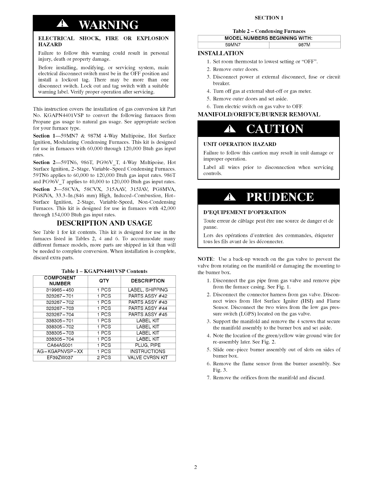
INSTALLATION
1. Set room thermostat to lowest setting or "OFF".
2. Remove outer doors.
3. Disconnect power at external disconnect, fuse or circuit
breaker.
4. Turn off gas at external shut-off or gas meter.
5. Remove outer doors and set aside.
6. Turn electric switch on gas valve to OFF.
MANIFOLD/ORIFICE/BURNER REMOVAL
[]NIT OPERATION HAZARD
Failure to follow this caution may result in unit damage or
improper operation.
Label all wires prior to disconnection when servicing
controls.
D'EQUIPEMENT D'OPERATION
Toute erreur de cfiblage peut _tre une source de danger et de
panne.
Lors des opOrations d'entretien des commandes, Otiqueter
tous les ills avant de les dOconnecter.
NOTE: Use a back-up wrench on the gas valve to prevent the
valve from rotating on the manifold or damaging the mounting to
the burner box.
1. Disconnect the gas pipe from gas valve and remove pipe
from the furnace casing. See Fig. 1.
2. Disconnect the connector harness from gas valve. Discon-
nect wires from Hot Surface Igniter (HSI) and Flame
Sensor. Disconnect the two wires from the low gas pres-
sure switch (LGPS) located on the gas valve.
3. Support the manifold and remove the 4 screws that secure
the manifold assembly to the burner box and set aside.
4. Note the location of the green/yellow wire ground wire for
re-assembly later. See Fig. 2.
5. Slide one-piece burner assembly out of slots on sides of
burner box.
6. Remove the flame sensor from the burner assembly. See
Fig. 3.
7. Remove the orifices from the manifold and discard.
/CAPAC]TO_
POWERCHOKE
REPRESENTATIVE DRAW]N G ONLY, SOME MODELS MAY VARY IN APPEARANCE
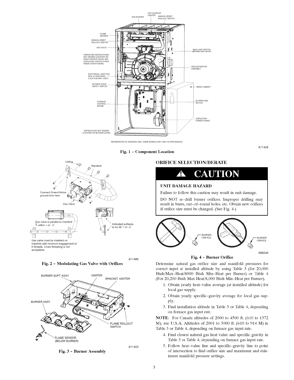
Fig. 1 -Component Location
Al1408
Orifice
Manifold ORIFICE SELECTION/DERATE
Connect Green/Yellow
ground wire here
J
Gas Valve
/
UNIT DAMAGE HAZARD
Failure to follow this caution may result in unit damage.
DO NOT re-drill burner orifices. Improper drilling may
result in burrs, out-of-round holes, etc. Obtain new orifices
if orifice size must be changed. (See Fig. 4.)
Gas valve is parallel to manifold ,'_ :/
CLwithin + or - 3 j
Gas valve must be installed on
manifold with minimum engagement of
6 threads, Cross threading is not
acceptaMe.
Fig. 2- Modulating Gas Valve with Orifices
Al1486
BURNER SUP]: ASSY
BURNER_SY
_"""_ FLA M E SENSOR
(BELOW BURNER)
IGNITER
TER
_ F_IMEHROLLOUT
Al1403
Fig. 3 - Burner Assembly
A96249
Fig. 4 - Burner Orifice
Deternfine natural gas orifice size and manifold pressures for
correct input at installed altitude by using Table 3 (for 20,000
Btuh/Max-Heat/8000 Btuh Min-Heat per Burner) or Table 4
(For 20,200 Btuh Max Heat/8,000 Btuh Min-Heat per Burner).
1. Obtain yearly heat-value average (at installed altitude) for
local gas supply.
2. Obtain yearly specific-gravity average for local gas sup-
ply.
3. Find installation altitude in Table 3 or Table 4, depending
on Nrnace gas input rate.
NOTE: For Canada altitudes of 2000 to 4500 ft. (610 to 1372
M), use U.S.A. Altitudes of 2001 to 3000 ft. (610 to 914 M) in
Table 3 or Table 4, depending on Nrnace gas input rate.
4. Find closest natural gas heat value and specific gravity in
Table 3 or Table 4, depending on Nrnace gas input rate.
5. Follow heat-value line and specific-gravity line to point
of intersection to find orifice size and maximum and nfin-
imum manifold pressure settings.
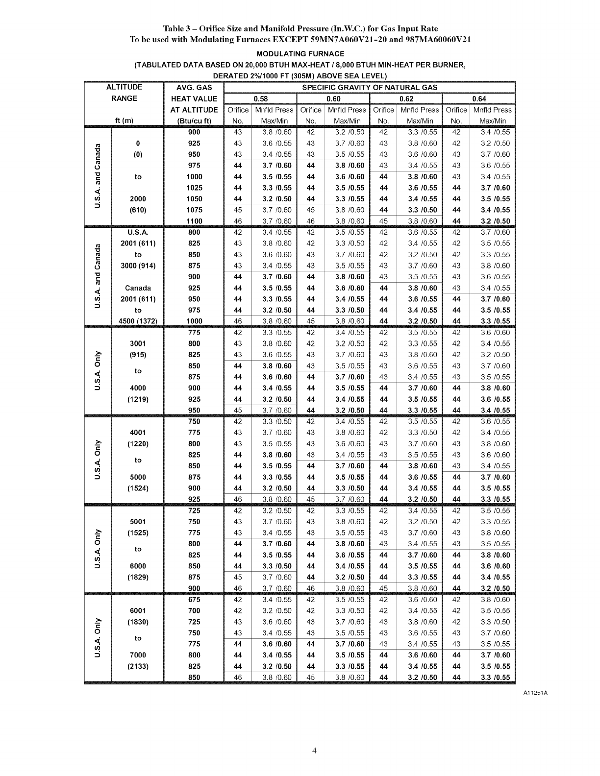
Table 3- Orifice Size and Manifold Pressure (In.W.C.) for Gas Input Rate
To be used with Modulating Furnaces EXCEPT 59MNTA060V21-20 and 987MA60060V21
MODULATING FURNACE
(TABULATED DATA BASED ON 20,000 BTUH MAX-HEAT /8,000 BTUH MIN-HEAT PER BURNER,
DERATED 2%H000 FT (305M) ABOVE SEA LEVEL)
ALTITUDE AVG. GAS SPECIFIC GRAVITY OF NATURAL GAS
RANGE HEAT VALUE 0.58 0.60 0.62 0.64
ft(m)
AT ALTITUDE Orifice Mnfld Press Orifice Mnfld Press Orifice Mnfld Press Orifice Mnfld Press
No. Max/Min No. Max/Min No. Max/Min No. Max/Min
900 43 3.8 /0.60 42 3.2 /0.50 42 3.3 /0.55 42 3.4 /0.55
113
C
113
L)
c
113
u')
0
(o)
to
2000
(610)
U.S.A.
925 43 3.6 /0.55 43 3.7 /0.60 43 3.8 /0.60 42 3.2 /0.50
950 43 3.4 /0.55 43 3.5 /0.55 43 3.6 /0.60 43 3.7 /0.60
975 44 3.7 /0.60 44 3.8 /0.60 43 3.4 /0.55 43 3.6 /0.55
1000 44 3.5 /0.55 44 3.6 /0.60 44 3.8 /0.60 43 3.4 /0.55
1025 44 3.3 /0.55 44 3.5 /0.55 44 3.6 /0.55 44 3.7 /0.60
1050 44 3.2 /0.50 44 3.3 /0.55 44 3.4/0.55 44 3.5 /0.55
1075 45 3.7 /0.60 45 3.8 /0.60 44 3.3 /0.50 44 3.4/0.55
1100 46 3.7 /0.60 46 3.8 /0.60 45 3.8 /0.60 44 3.2 /0.50
800 42 3.4 /0.55 42 3.5 /0.55 42 3.6 /0.55 42 3.7 /0.60
113
C
C
113
2001 (611)
to
3000 (914)
Canada
2001 (611)
to
825 43 3.8 /0.60 42 3.3 /0.50 42 3.4 /0.55 42 3.5 /0.55
850 43 3.6 /0.60 43 3.7 /0.60 42 3.2 /0.50 42 3.3 /0.55
875 43 3.4 /0.55 43 3.5 /0.55 43 3.7 /0.60 43 3.8 /0.60
900 44 3.7 /0.60 44 3.8 /0.60 43 3.5 /0.55 43 3.6 /0.55
925 44 3.5 /0.55 44 3.6 /0.60 44 3.8 /0.60 43 3.4 /0.55
950 44 3.3 /0.55 44 3.4/0.55 44 3.6 /0.55 44 3.7 /0.60
975 44 3.2 /0.50 44 3.3 /0.50 44 3.4/0.55 44 3.5 /0.55
4500 (1372) 1000 46 3.8 /0.60 45 3.8 /0.60 44 3.2 /0.50 44 3.3 /0.55
775 42 3.3 /0.55 42 3.4 /0.55 42 3.5 /0.55 42 3.6 /0.60
c
O
3001
(915)
to
4000
800 43 3.8 /0.60 42 3.2 /0.50 42 3.3 /0.55 42 3.4 /0.55
825 43 3.6 /0.55 43 3.7 /0.60 43 3.8 /0.60 42 3.2 /0.50
850 44 3.8 /0.60 43 3.5 /0.55 43 3.6 /0.55 43 3.7 /0.60
875 44 3.6 /0.60 44 3.7 /0.60 43 3.4 /0.55 43 3.5 /0.55
900 44 3.4/0.55 44 3.5 /0.55 44 3.7 /0.60 44 3.8 /0.60
(1219) 925 44 3.2 /0.50 44 3.4/0.55 44 3.5 /0.55 44 3.6 /0.55
950 45 3.7 /0.60 44 3.2 /0.50 44 3.3 /0.55 44 3.4/0.55
750 42 3.3 /0.50 42 3.4 /0.55 42 3.5 /0.55 42 3.6 /0.55
u')
4001
(1220)
to
5000
775 43 3.7 /0.60 43 3.8 /0.60 42 3.3 /0.50 42 3.4 /0.55
800 43 3.5 /0.55 43 3.6 /0.60 43 3.7 /0.60 43 3.8 /0.60
825 44 3.8 /0.60 43 3.4 /0.55 43 3.5 /0.55 43 3.6 /0.60
850 44 3.5 /0.55 44 3.7 /0.60 44 3.8 /0.60 43 3.4 /0.55
875 44 3.3 /0.55 44 3.5 /0.55 44 3.6 /0.55 44 3.7 /0.60
(1524) 900 44 3.2 /0.50 44 3.3 /0.50 44 3.4/0.55 44 3.5 /0.55
925 46 3.8 /0.60 45 3.7 /0.60 44 3.2 /0.50 44 3.3 /0.55
725 42 3.2 /0.50 42 3.3 /0.55 42 3.4 /0.55 42 3.5 /0.55
c
O
5001
(1525)
to
6000
750 43 3.7 /0.60 43 3.8 /0.60 42 3.2 /0.50 42 3.3 /0.55
775 43 3.4 /0.55 43 3.5 /0.55 43 3.7 /0.60 43 3.8 /0.60
800 44 3.7 /0.60 44 3.8 /0.60 43 3.4 /0.55 43 3.5 /0.55
825 44 3.5 /0.55 44 3.6 /0.55 44 3.7 /0.60 44 3.8 /0.60
850 44 3.3 /0.50 44 3.4/0.55 44 3.5 /0.55 44 3.6 /0.60
(1829) 875 45 3.7 /0.60 44 3.2 /0.50 44 3.3 /0.55 44 3.4/0.55
900 46 3.7 /0.60 46 3.8 /0.60 45 3.8 /0.60 _ 3.2 /0.50
675 42 3.4 /0.55 42 3.5 /0.55 42 3.6 /0.60 42 3.8 /0.60
6001
--_ (1830)
_ to
7000
700 42 3.2 /0.50 42 3.3 /0.50 42 3.4 /0.55 42 3.5 /0.55
725 43 3.6 /0.60 43 3.7 /0.60 43 3.8 /0.60 42 3.3 /0.50
750 43 3.4 /0.55 43 3.5 /0.55 43 3.6 /0.55 43 3.7 /0.60
775 44 3.6 /0.60 44 3.7 /0.60 43 3.4 /0.55 43 3.5 /0.55
800 44 3.4/0.55 44 3.5 /0.55 44 3.6 /0.60 44 3.7 /0.60
(2133) 825 44
850 46
3.2 /0.50 44 3.3 /0.55 44 3.4/0.55 44 3.5 /0.55
38/060 42._ 38/060 32/o.5o 33/o.5
Al1251A
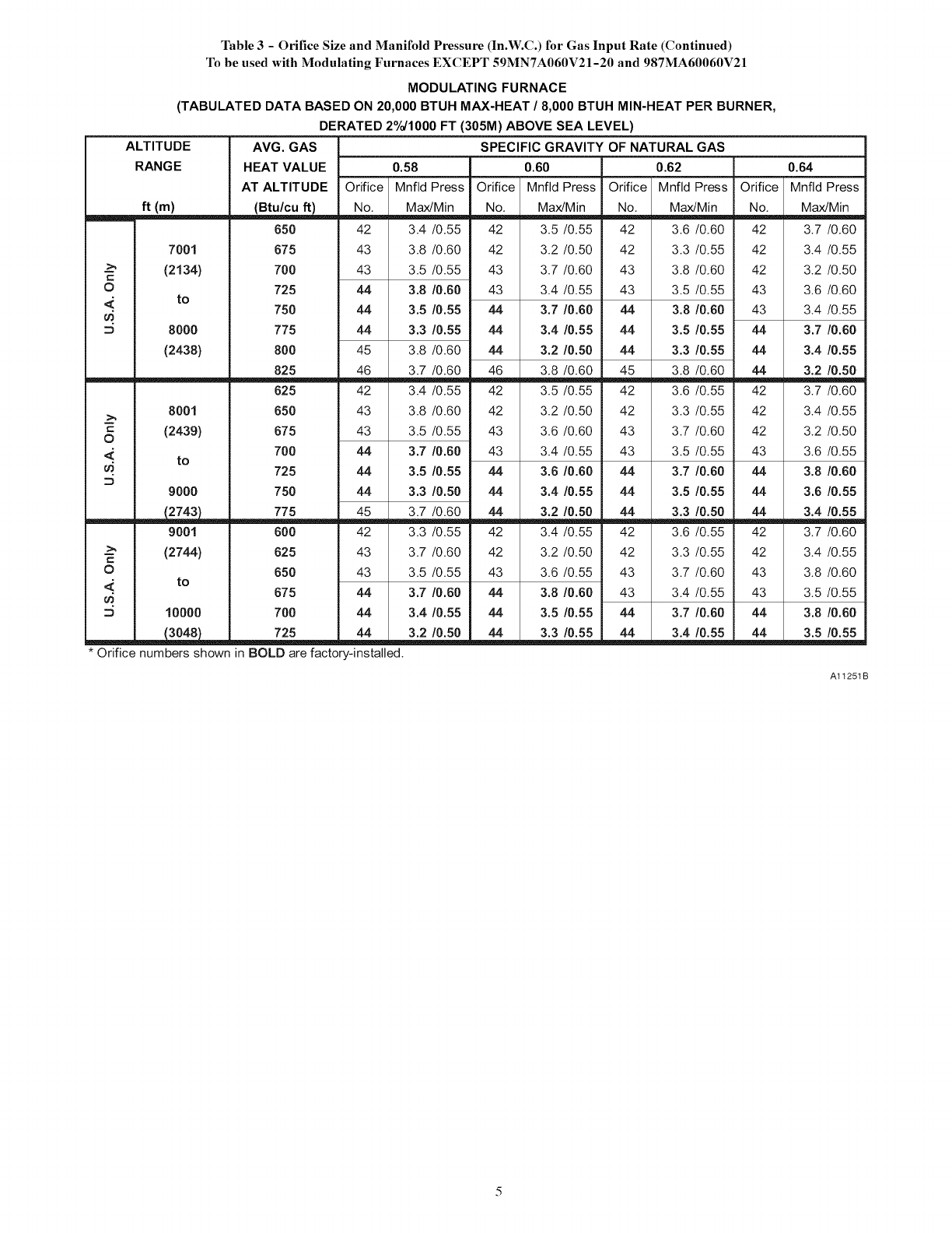
Table 3 - Orifice Size and Manifold Pressure (In.W.C.) for Gas Input Rate (Continued)
To be used with Modulating Furnaces EXCEPT 59MN7A060V21-20 and 987MA60060V21
MODULATING FURNACE
(TABULATED DATA BASED ON 20,000 BTUH MAX.HEAT /8,000 BTUH MIN-HEAT PER BURNER,
DERATED 2°/o/1000 FT (305M) ABOVE SEA LEVEL)
ALTITUDE
RANGE
ft (m)
7001
--_ (2134)
0
_ to
D 8000
(2438)
8001
= (2439)
0
_ to
9000
9001
-->' (2744)
O
_ to
D10000
_ 725 44 3.2 /0.50
* Orifice numbers shown in BOLD are factory-installed.
AVG. GAS
HEAT VALUE 0.58
AT ALTITUDE Orifice Mnfid Press Orifice
(Btu/cu ft) No, Max/Min No,
650 42 3.4 /0.55 42
675 43 3.8 /0.60 42
700 43 3.5 /0.55 43
725 44 3.8 /0.60 43
750 44 3.5 /0.55 44
775 44 3.3 /0.55 44
800 45 3.8 /0.60 44
825 46 3.7 /0.60 46
625 42 3.4 /0.55 42
650 43 3.8 /0.60 42
675 43 3.5 /0.55 43
700 44 3.7 /0.60 43
725 44 3.5 /0.55 44
750 44 3.3 /0.50 44
775 45 3.7 /0.60 44
600 42 3.3 /0.55 42
625 43 3.7 /0.60 42
650 43 3.5 /0.55 43
675 44 3.7 /0.60 44
700 44 3.4/0.55 44
4_4_
SPECIFIC GRAVITY OF NATURAL GAS
0.60 0.62
Mnfld Press Orifice Mnfld Press Orifice
Max/Min No, Max/Min No,
3.5 /0.55 42 3.6 /0.60 42
3.2 /0.50 42 3.3 /0.55 42
3.7 /0.60 43 3.8 /0.60 42
3.4 /0.55 43 3.5 /0.55 43
3.7 /0.60 44 3.8 /0.60 43
3.4 /0.55 44 3.5 /0.55 44
3.2 /0.50 44 3.3 /0.55 44
3.8 /0.60 45 3.8 /0.60 44
3.5 /0.55 42 3.6 /0.55 42
3.2 /0.50 42 3.3 /0.55 42
3.6 /0.60 43 3.7 /0.60 42
3.4 /0.55 43 3.5 /0.55 43
3.6 /0.60 44 3.7 /0.60 44
3.4 /0.55 44 3.5 /0.55 44
3.2 /0.50 44 3.3 /0.50 44
3.4 /0.55 42 3.6 /0.55 42
3.2 /0.50 42 3.3 /0.55 42
3.6 /0.55 43 3.7 /0.60 43
3.8 /0.60 43 3.4 /0.55 43
3.5 /0.55 44 3.7 /0.60 44
3.3 /0.55 44 3.4 /0.55 44
0.64
Mnfid Press
Max/Min
3.7 /0.60
3.4 /0.55
3.2 /0.50
3.6 /0.60
3.4 /0.55
3.7 /0.60
3.4 /0.55
3.2 /0.50
3.7 /0.60
3.4 /0.55
3.2 /0.50
3.6 /0.55
3.8 /0.60
3.6 /0.55
3.4 /0.55
3.7 /0.60
3.4 /0.55
3.8 /0.60
3.5 /0.55
3.8 /0.60
3.5 /0.55
Al1251B
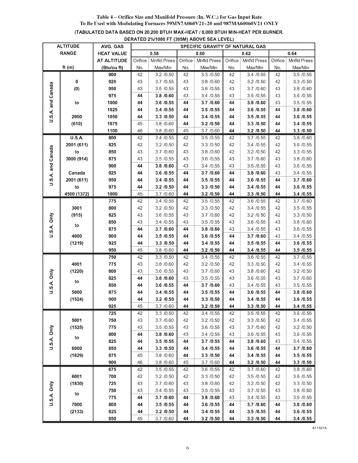
Table 4 - Orifice Size and Manifold Pressure (In. W.C.) for Gas Input Rate
To Be Used with Modulating Furnaces 59MN7A060V21-20 and 987MA60060V21 ONLY
(TABULATED DATA BASED ON 20,200 BTUH MAX-HEAT /8,000 BTUH MIN-HEAT PER BURNER,
DERATED 2%/1000 FT (305M) ABOVE SEA LEVEL)
ALTITUDE AVG. GAS SPECIFIC GRAVITY OF NATURAL GAS
RANGE HEAT VALUE 0.58 0.60 0.62 0.64
AT ALTITUDE Orifice Mnfld Press Orifice Mnfld Press Orifice Mnfld Press Orifice Mnfld Press
ft (m) _ No. Max/Min No. Max/Min No. Max/Min No. Max/Min
900 42 3.2 /0.50 42 3.3 /0.50 42 3.4 /0.55 42 3.5 /0.55
0925 43 3.7 /0.55 43 3.8 /0.60 42 3.2 /0.50 42 3.3 /0.50
(0) 950 43 3.5 /0.55 43 3.6 /0.55 43 3.7 /0.60 43 3.8 /0.60
t..
o 975 44 3.8/0.60 43 3.4/0.55 43 3.5/0.55 43 3.6/0.55
to 1000 44 3.6/0.55 44 3.7/0.60 44 3.8/0.60 43 3.5/0.55
<' 1025 44 3.4 /0.55 44 3.5 /0.55 44 3.6 /0.55 44 3.8 /0.60
2000 1050 44 3.3 /0.50 44 3.4 /0.55 44 3.5 /0.55 44 3.6 /0.55
(610) 1075 45 3.8 /0.60 44 3.2 /0.50 44 3.3 /0.50 44 3.4 /0.55
1100 46 3.8 /0.60 45 3.7 /0.60 44 3.2 /0.50 44 3.3 /0.50
U.S.A. 800 42 3.4/0.55 42 3.5/0.55 42 3.7/0.55 42 3.8/0.60
2001 (611) 825 42 3.2/0.50 42 3.3/0.50 42 3.4/0.55 42 3.6/0.55
to 850 43 3.7/0.60 43 3.8/0.60 42 3.2/0.50 42 3.3/0.55
t..
3000 (914) 875 43 3.5/0.55 43 3.6/0.55 43 3.7/0.60 43 3.8/0.60
900 44 3.8/0.60 43 3.4/0.55 43 3.5/0.55 43 3.6/0.55
_. Canada 925 44 3.6/0.55 44 3.7/0.60 44 3.8/0.60 43 3.4/0.55
2001 (611) 950 44 3.4/0.55 44 3.5/0.55 44 3.6/0.55 44 3.7/0.60
to 975 44 3.2/0.50 44 3.3/0.50 44 3.4/0.55 44 3.6/0.55
__ 1000 45 3.7/0.60 44 3.2/0.50 44 3.3/0.50 44 3.4/0.55
775 42 3.4/0.55 42 3.5/0.55 42 3.6/0.55 42 3.7/0.60
3001 800 42 3.2/0.50 42 3.3/0.50 42 3.4/0.55 42 3.5/0.55
.-_ (915) 825 43 3.6/0.55 43 3.7/0.60 42 3.2/0.50 42 3.3/0.50
O 850 43 3.4/0.55 43 3.5/0.55 43 3.6/0.55 43 3.8/0.60
_' to 875 44 3.7/0.60 44 3.8/0.60 43 3.4/0.55 43 3.6/0.55
4000 900 44 3.5/0.55 44 3.6/0.55 44 3.7/0.60 43 3.4/0.55
(1219) 925 44 3.3/0.50 44 3.4/0.55 44 3.5/0.55 44 3.6/0.55
950 45 3.8/0.60 44 3.2/0.50 44 3.4/0.55 44 3.5/0.55
750 42 3.3/0.50 42 3.4/0.55 42 3.6/0.55 42 3.7/0.55
4001 775 43 3.8/0.60 42 3.2/0.50 42 3.3/0.50 42 3.4/0.55
.-_ (1220) 800 43 3.6/0.55 43 3.7/0.60 43 3.8/0.60 42 3.2/0.50
t..
O 825 44 3.8/0.60 43 3.5/0.55 43 3.6/0.55 43 3.7/0.60
to 850 44 3.6 /0.55 44 3.7 /0.60 43 3.4 /0.55 43 3.5 /0.55
5000 875 44 3.4 /0.55 44 3.5 /0.55 44 3.6 /0.55 44 3.8 /0.60
(1524) 900 44 3.2 /0.50 44 3.3 /0.50 44 3.4 /0.55 44 3.6 /0.55
925 45 3.7 /0.60 44 3.2 /0.50 44 3.3 /0.50 44 3.4 /0.55
725 42 3.3 /0.50 42 3.4 /0.55 42 3.5 /0.55 42 3.6 /0.55
5001 750 43 3.7 /0.60 42 3.2 /0.50 42 3.3 /0.50 42 3.4 /0.55
(1525) 775 43 3.5 /0.55 43 3.6 /0.55 43 3.7 /0.60 42 3.2 /0.50
t..
O 800 44 3.8/0.60 43 3.4/0.55 43 3.5/0.55 43 3.6/0.55
to 825 44 3.5/0.55 44 3.7/0.55 44 3.8/0.60 43 3.4/0.55
6000 850 44 3.3 /0.50 44 3.4 /0.55 44 3.6 /0.55 44 3.7 /0.60
(1829) 875 45 3.8 /0.60 44 3.3 /0.50 44 3.4 /0.55 44 3.5 /0.55
900 46 3.8 /0.60 45 3.7 /0.60 44 3.2 /0.50 44 3.3 /0.50
675 42 3.5 /0.55 42 3.6 /0.55 42 3.7 /0.60 42 3.8 /0.60
6001 700 42 3.2 /0.50 42 3.3 /0.50 42 3.5 /0.55 42 3.6 /0.55
.-_ (1830) 725 43 3.7 /0.60 43 3.8 /0.60 42 3.2 /0.50 42 3.3 /0.50
t..
O 750 43 3.4/0.55 43 3.5/0.55 43 3.7/0.55 43 3.8/0.60
to 775 44 3.7 /0.60 44 3.8 /0.60 43 3.4 /0.55 43 3.5 /0.55
7000 800 44 3.5 /0.55 44 3.6 /0.55 44 3.7 /0.60 44 3.8 /0.60
(2133) 825 44 3.2 /0.50 44 3.4 /0.55 44 3.5 /0.55 44 3.6 /0.55
850 45 3.7 /0.60 44 3.2 /0.50 44 3.3 /0.50 44 3.4 /0.55
Al1621A
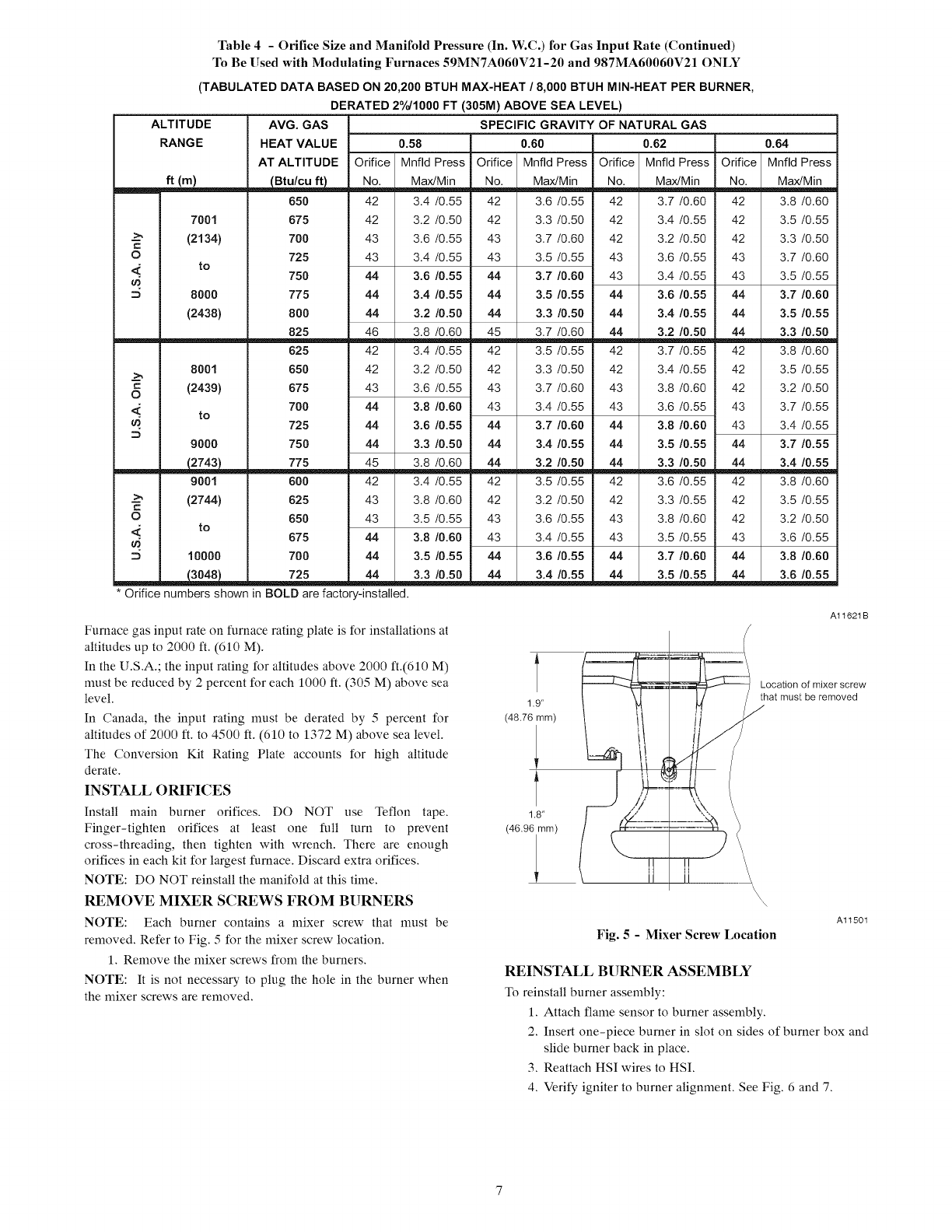
Table 4 -Orifice Size and Manifold Pressure (In. W.C.) for Gas Input Rate (Continued)
To Be Used with Modulating Furnaces 59MN7A060V21-20 and 987MA60060V21 ONLY
(TABULATED DATA BASED ON 20,200 BTUH MAX-HEAT /8,000 BTUH MIN-HEAT PER BURNER,
DERATED 2°/o/1000 FT (305M) ABOVE SEA LEVEL)
ALTITUDE
RANGE
ft (m)
7001
--_ (2134)
O
to
8000
(2438)
8001
=(2439)
O
to
9000
AVG. GAS SPECIFIC GRAVITY OF NATURAL GAS
HEAT VALUE 0.58 0.60 0.62
AT ALTITUDE Orifice Mnfld Press Orifice Mnfld Press Orifice Mnfld Press
No. Max/Min No. Max/Min No. Max/Min
650 42 3.4 /0.55 42 3.6 /0.55 42 3.7 /0.60
675 42 3.2 /0.50 42 3.3 /0.50 42 3.4 /0.55
700 43 3.6 /0.55 43 3.7 /0.60 42 3.2 /0.50
725 43 3.4 /0.55 43 3.5 /0.55 43 3.6 /0.55
750 44 3,6 /0.55 44 3,7 /0.60 43 3.4 /0.55
775 44 3,4/0,55 44 3,5 /0,55 44 3,6 /0.55
800 44 3.2 /0.50 44 3.3 /0.50 44 3,4 /0,55
825 46 3.8 /0.60 45 3.7 /0.60 44 3,2 /0,50
625 42 3.4 /0.55 42 3.5 /0.55 42 3.7 /0.55
650 42 3.2 /0.50 42 3.3 /0.50 42 3.4 /0.55
675 43 3.6 /0.55 43 3.7 /0.60 43 3.8 /0.60
700 44 3,8 /0.60 43 3.4 /0.55 43 3.6 /0.55
725 44 3,6 /0,55 44 3,7 /0.60 44 3,8 /0,60
750 44 3.3 /0.50 44 3,4 /0,55 44 3,5 /0,55
45 3.8 /0.60 44 3,2 /0,50 44 3,3 /0,50
42 3.4 /0.55 42 3.5 /0.55 42 3.6 /0.55
43 3.8 /0.60 42 3.2 /0.50 42 3.3 /0.55
43 3.5 /0.55 43 3.6 /0.55 43 3.8 /0.60
44 3,8 /0,60 43 3.4 /0.55 43 3.5 /0.55
44 3,5 /0,55 44 3,6 /0,55 44 3,7 /0,60
3,5 /0.55
__ 775
9001 600
(2744) 625
O 650
to 675
10000 700
_ 725 4.._.L43.3/0.50 4_..&4 3.4/0.5_ 4.....£_4
*Orifice numbers shown in BOLD are factory-installed.
0,64
Orifice Mnfld Press
No. Max/Min
42 3.8 /0.60
42 3.5 /0.55
42 3.3 /0.50
43 3.7 /0.60
43 3.5 /0.55
44 3,7 /0,60
44 3,5 /0,55
44 3,3 /0,50
42 3.8 /0.60
42 3.5 /0.55
42 3.2 /0.50
43 3.7 /0.55
43 3.4 /0.55
44 3,7 /0,55
44 3,4 /0,55
42 3.8 /0.60
42 3.5 /0.55
42 3.2 /0.50
43 3.6 /0.55
44 3,8 /0,60
44 3.6 /0,55
Furnace gas input rate on furnace rating plate is for installations at
altitudes up to 2000 ft. (610 M). A
In the U.S.A.; the input rating for altitudes above 2000 fl.(610 M) l
must be reduced by 2 percent for each 1000 ft. (305 M) above sea /
level. 1.9"
In Canada, the input rating must be derated by 5 percent for (48.76mm)
altitudes of 2000 ft. to 4500 ft. (610 to 1372 M) above sea level. /
The Conversion Kit Rating Plate accounts for high altitude
derate.
INSTALL ORIFICES l
18"
(46.96 mm)
Install main burner orifices. DO NOT use Teflon tape.
Finger-tighten orifices at least one full turn to prevent
cross-threading, then tighten with wrench. There are enough
orifices in each kit for largest furnace. Discard extra orifices.
NOTE: DO NOT reinstall the manifold at this time.
REMOVE MIXER SCREWS FROM BURNERS
NOTE: Each burner contains a mixer screw that must be
removed. Refer to Fig. 5 for the mixer screw location.
1. Remove the mixer screws from the burners.
NOTE: It is not necessary to plug the hole in the burner when
the mixer screws are removed.
Al1621B
(\11
Location of mixer screw
..._hat must be removed
\\\\
Al1501
Fig. 5 - Mixer Screw Location
REINSTALL BURNER ASSEMBLY
To reinstall burner assembly:
1. Attach flame sensor to burner assembly.
2. Insert one-piece burner in slot on sides of burner box and
slide burner back in place.
3. Reattach HSI wires to HSI.
4. Verify igniter to burner alignment. See Fig. 6 and 7.
ql !
(64.4)
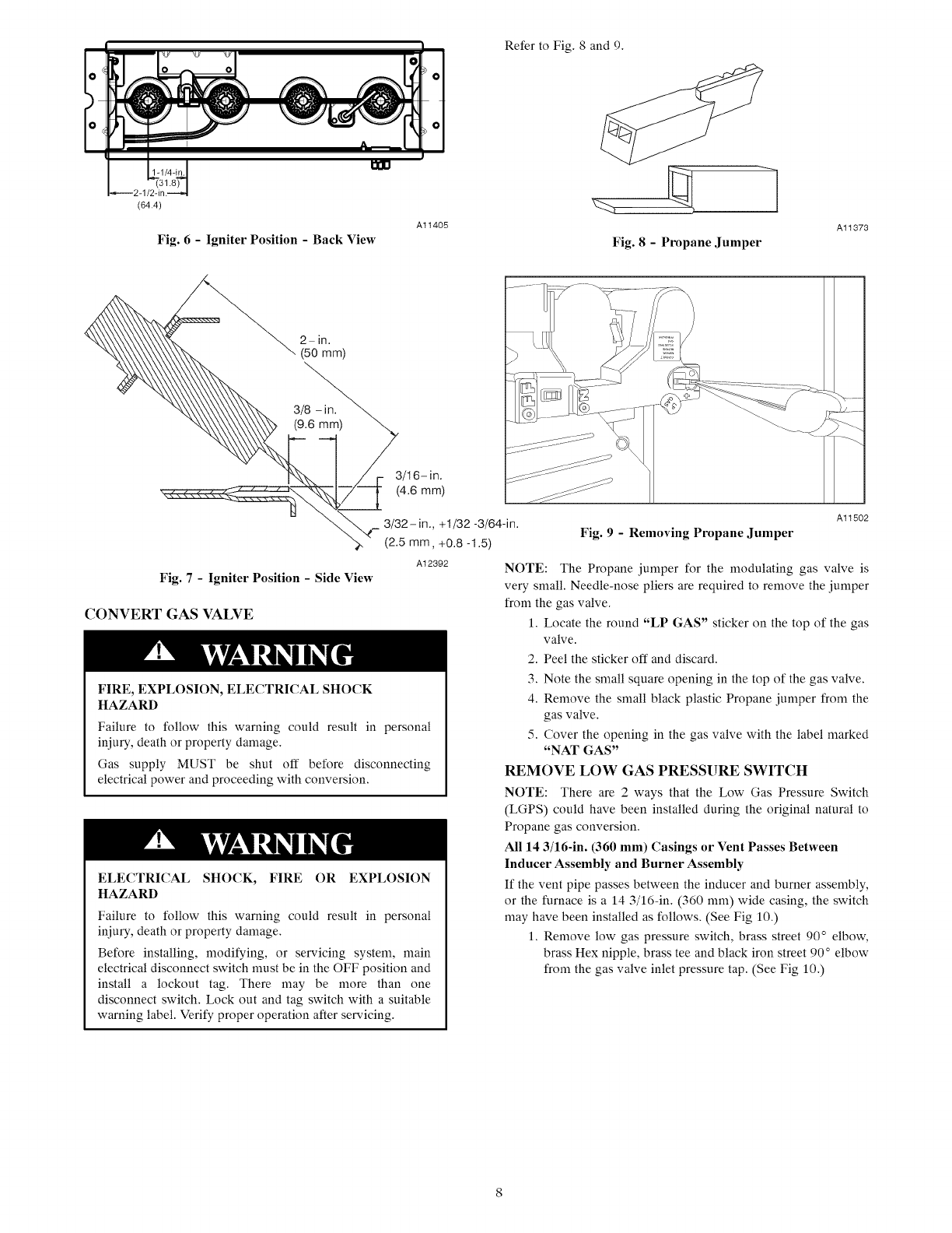
Fig. 6 - Igniter Position - Back View
Al1405
Refer to Fig. 8 and 9.
Fig. 8-Propane Jumper
Al1373
2- iiq.
(50 mm)
3/16- in.
(4.6 mm)
A12392
Fig. 7 -Igniter Position - Side View
CONVERT GAS VALVE
FIRE, EXPLOSION, ELECTRICAL SHOCK
HAZARD
Failure to follow this warning could result in personal
iniury, death or property damage.
Gas supply MUST be shut off before disconnecting
electrical power and proceeding with conversion.
ELECTRICAL SHOCK, FIRE OR EXPLOSION
HAZARD
Failure to follow this warning could result in personal
iniury, death or property damage.
Before installing, modifying, or servicing system, main
electrical disconnect switch nmst be in the OFF position and
install a lockout tag. There may be more than one
disconnect switch. Lock out and tag switch with a suitable
warning label. Verify proper operation after servicing.
Fig. 9- Removing Propane Jumper
Al1502
NOTE: The Propane jumper for the modulating gas valve is
very small. Needle-nose pliers are required to remove the jumper
from the gas valve,
1. Locate the round "LP GAS" sticker on the top of the gas
valve.
2. Peel the sticker off and discard.
3, Note the small square opening in the top of the gas valve.
4, Remove the small black plastic Propane jumper from the
gas valve.
5, Cover the opening in the gas valve with the label marked
"NAT GAS"
REMOVE LOW GAS PRESSURE SWITCH
NOTE: There are 2 ways that the Low Gas Pressure Switch
(LGPS) could have been installed during the original natural to
Propane gas conversion.
All 14 3/16-in. (360 mm) Casings or Vent Passes Between
Inducer Assembly and Burner Assembly
If the vent pipe passes between the inducer and burner assembly,
or the furnace is a 14 3/16-in. (360 ram) wide casing, the switch
may have been installed as follows. (See Fig 10.)
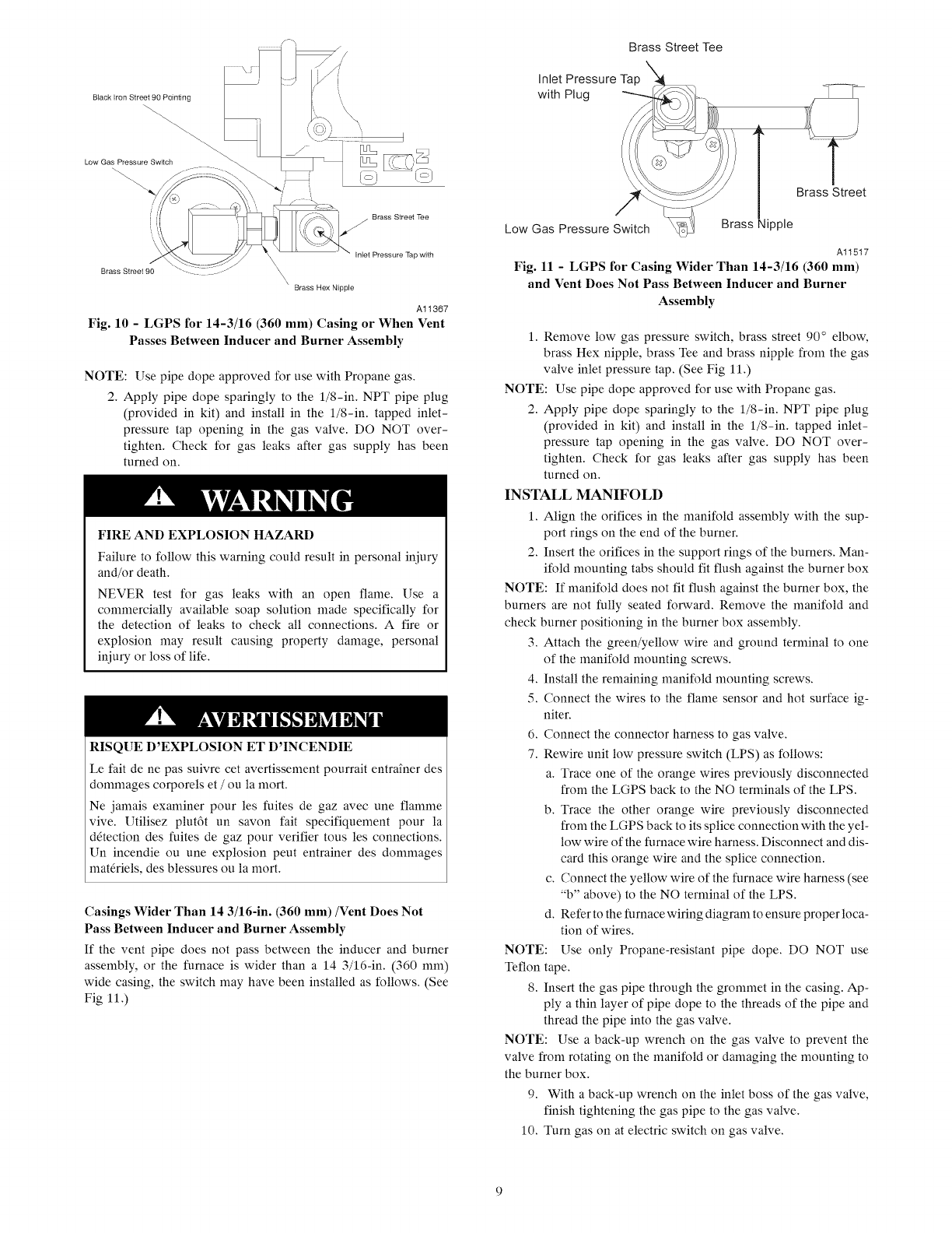
1. Remove low gas pressure switch, brass street 90° elbow,
brass Hex nipple, brass tee and black iron street 90 ° elbow
from the gas valve inlet pressure tap. (See Fig 10.)
Brass Street Tee
Inlet Pressure Tap
with Plug
Brass Hex Nipple
A11367
Fig. 10 -LGPS for 14-3/16 (360 mm) Casing or When Vent
Passes Between Inducer and Burner Assembly
NOTE: Use pipe dope approved for use with Propane gas.
2. Apply pipe dope sparingly to the l/8-in. NPT pipe plug
(provided in kit) and install in the l/8-in, tapped inlet-
pressure tap opening in the gas valve. DO NOT over-
tighten. Check for gas leaks after gas supply has been
turned on.
FIRE AND EXPLOSION HAZARD
Failure to follow this warning could result in personal injury
and/or death.
NEVER test for gas leaks with an open flame. Use a
commercially available soap solution made specifically for
the detection of leaks to check all connections. A fire or
explosion may result causing property damage, personal
injury or loss of life.
RISQUE D'EXPLOSION ET D'INCENDIE
Le fair de ne pas suivre cet avertissement pourrait entra*ner des
dommages corporels et /ou la mort.
Ne jamais examiner pour les fuites de gaz avec une flamme
vive. Utilisez plut6t un savon fair specifiquement pour la
d6tection des fuites de gaz pour verifier tousles connections.
Un incendie ou une explosion peut entrainer des dommages
mat6riels, des blessures ou la mort.
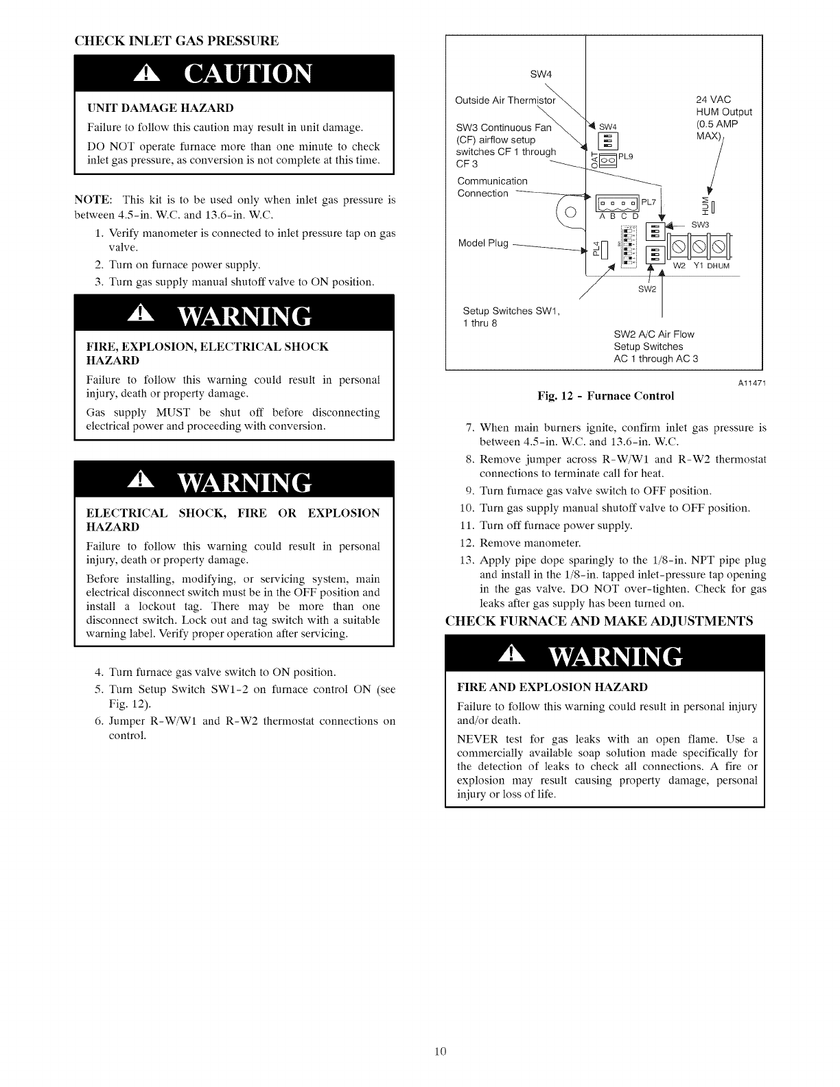
Casings Wider Than 14 3/16-in. (360 mm)/Vent Does Not
Pass Between Inducer and Burner Assembly
If the vent pipe does not pass between the inducer and burner
assembly, or the furnace is wider than a 14 3/16-in. (360 ram)
wide casing, the switch may have been installed as follows. (See
Fig 11.)
Brass Street
Low Gas Pressure Switch Brass Nipple
Al1517
Fig. 11 -LGPS for Casing Wider Than 14-3/16 (360 mm)
and Vent Does Not Pass Between Inducer and Burner
Assembly
1. Remove low gas pressure switch, brass street 90 ° elbow,
brass Hex nipple, brass Tee and brass nipple from the gas
valve inlet pressure tap. (See Fig 11.)
NOTE: Use pipe dope approved for use with Propane gas.
2. Apply pipe dope sparingly to the l/8-in. NPT pipe plug
(provided in kit) and install in the l/8-in, tapped inlet-
pressure tap opening in the gas valve. DO NOT over-
tighten. Check for gas leaks after gas supply has been
turned on.
INSTALL MANIFOLD
1. Align the orifices in the manifold assembly with the sup-
port rings on the end of the burner.
2. Insert the orifices in the support rings of the burners. Man-
ifold mounting tabs should fit flush against the burner box
NOTE: If manifold does not fit flush against the burner box, the
burners are not fully seated forward. Remove the manifold and
check burner positioning in the burner box assembly.
3. Attach the green/yellow wire and ground terminal to one
of the manifold mounting screws.
4. Install the remaining manifold mounting screws.
5. Connect the wires to the flame sensor and hot surface ig-
niter.
6. Connect the connector harness to gas valve.
7. Rewire unit low pressure switch (LPS) as follows:
a. Trace one of the orange wires previously disconnected
from the LGPS back to the NO terminals of the LPS.
b. Trace the other orange wire previously disconnected
from the LGPS back to its splice connection with the yel-
low wire of the furnace wire harness. Disconnect and dis-
card this orange wire and the splice connection.
c. Connect the yellow wire of the furnace wire harness (see
"b" above) to the NO terminal of the LPS.
d. Refer to the furnace wiring diagram to ensure proper loca-
tion of wires.
NOTE: Use only Propane-resistant pipe dope, DO NOT use
Teflon tape.
8. Insert the gas pipe through the grommet in the casing. Ap-
ply a thin layer of pipe dope to the threads of the pipe and
thread the pipe into the gas valve.
NOTE: Use a back-up wrench on the gas valve to prevent the
valve from rotating on the manifold or damaging the mounting to
the burner box.
9. With a back-up wrench on the inlet boss of the gas valve,
finish tightening the gas pipe to the gas valve.
10. Turn gas on at electric switch on gas valve.
CHECK INLET GAS PRESSURE
UNIT DAMAGE HAZARD
Failure to follow this caution may result in unit damage.
DO NOT operate furnace more than one minute to check
inlet gas pressure, as conversion is not complete at this time.
NOTE: This kit is to be used only when inlet gas pressure is
between 4.5-in. W.C. and 13.6-in. W.C.
1. Verify manometer is connected to inlet pressure tap on gas
valve.
2. Turn on furnace power supply.
3. Turn gas supply manual shutoff valve to ON position.
FIRE, EXPLOSION, ELECTRICAL SHOCK
HAZARD
Failure to follow this warning could result in personal
injury, death or property damage.
Gas supply MUST be shut off before disconnecting
electrical power and proceeding with conversion.
ELECTRICAL SHOCK, FIRE OR EXPLOSION
HAZARD
Failure to follow this warning could result in personal
injury, death or property damage.
Before installing, modifying, or servicing system, main
electrical disconnect switch must be in the OFF position and
install a lockout tag. There may be more than one
disconnect switch. Lock out and tag switch with a suitaMe
warning label. Verify proper operation after servicing.
SW4
Outside Air Thermi,'
SW3 Continuous
(CF) airflow setup
switches CF 1 through
CF 3 _---_
Communication
24 VAC
HUM Output
(O.5AMP
}H
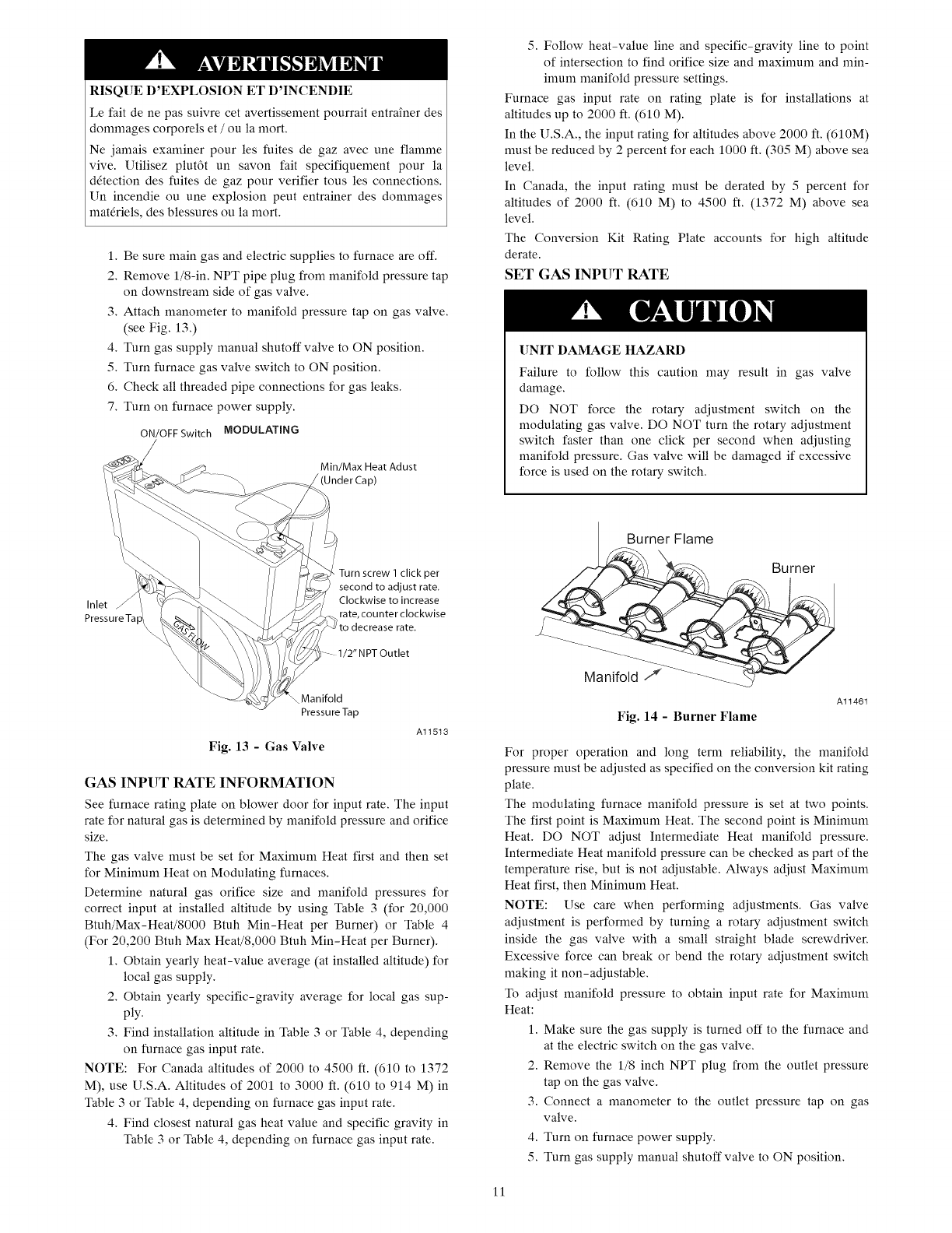
Fig. 12 -Furnace Control
Al1471
7. When main burners ignite, confirm inlet gas pressure is
between 4.5-in. W.C. and 13.6-in. W.C.
8. Remove jumper across R-W/WI and R-W2 thermostat
connections to terminate call for heat.
9. Turn furnace gas valve switch to OFF position.
10. Turn gas supply manual shutoff valve to OFF position.
11. Turn off furnace power supply.
12. Remove manometer.
13. Apply pipe dope sparingly to the l/8-in. NPT pipe plug
and install in the l/8-in, tapped inlet-pressure tap opening
in the gas valve. DO NOT over-tighten. Check for gas
leaks after gas supply has been turned on.
CHECK FURNACE AND MAKE ADJUSTMENTS
4. Turn furnace gas valve switch to ON position.
5. Turn Setup Switch SW1-2 on furnace control ON (see
Fig. 12).
6. Jumper R-W/W1 and R-W2 thermostat connections on
control.
FIRE AND EXPLOSION HAZARD
Failure to follow this warning could result in personal iniury
and/or death.
NEVER test for gas leaks with an open flame. Use a
commercially available soap solution made specifically for
the detection of leaks to check all connections. A fire or
explosion may result causing property damage, personal
iniury or loss of life.
10
RISQUE D'EXPLOSION ET D'INCENDIE
Le fait de ne pas suivre cet avertissement pourrait entra_ner des
dommages corporels et /ou la mort.
Ne jamais examiner pour les fuites de gaz avec une flamme
vive. Utilisez plut6t un savon fait specifiquement pour la
d6tection des fuites de gaz pour verifier tous les connections.
Un incendie ou une explosion peut entrainer des dommages
mat6riels, des blessures ou la mort.
1. Be sure main gas and electric supplies to furnace are off.
2. Remove l/8-in. NPT pipe plug from manifold pressure tap
on downstream side of gas valve.
3. Attach manometer to manifold pressure tap on gas valve.
(see Fig. 13.)
4. Turn gas supply manual shutoff valve to ON position.
5. Turn furnace gas valve switch to ON position.
6. Check all threaded pipe connections for gas leaks.
7. Turn on furnace power supply.
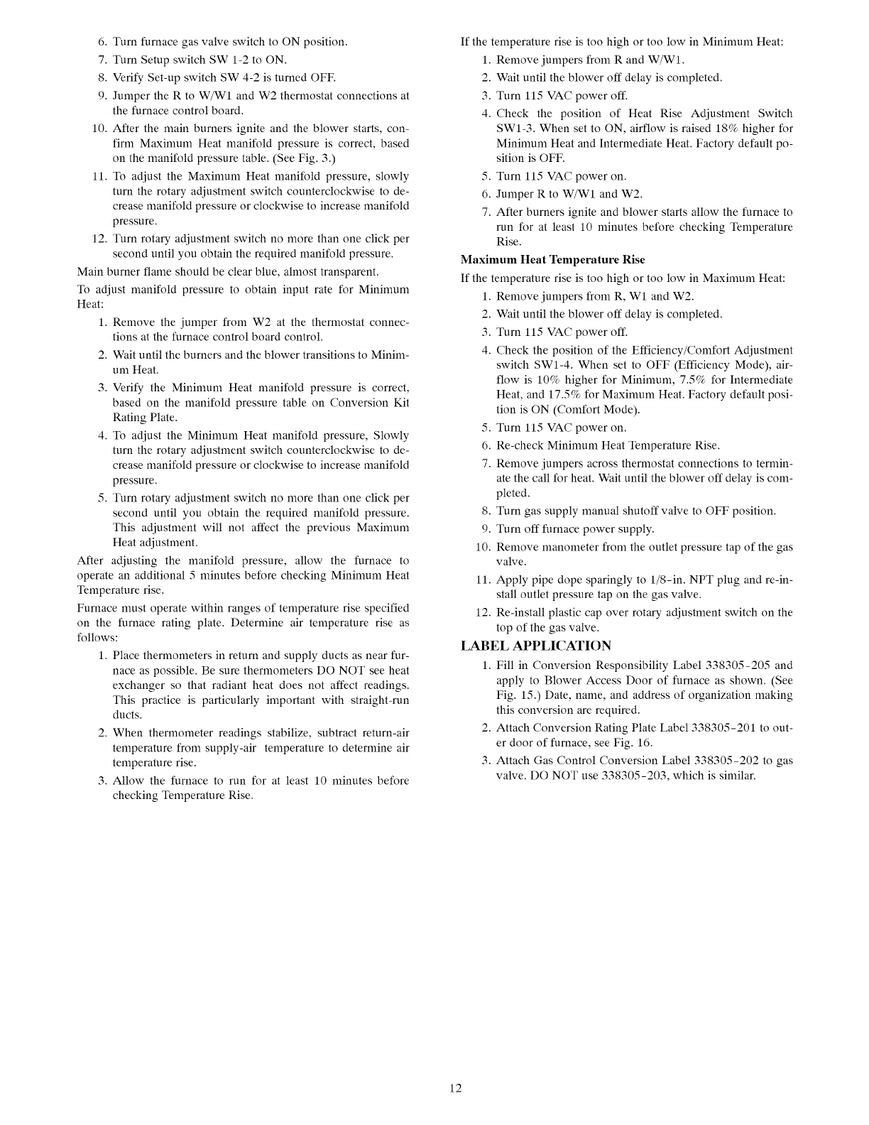
ON/OFFSwitch MODULATING
/
Min/Max Heat Adust
5. Follow heat-value line and specific-gravity line to point
of intersection to find orifice size and maximum and min-
imum manifold pressure settings.
Furnace gas input rate on rating plate is for installations at
altitudes up to 2000 ft. (610 M).
In the U.S.A., the input rating for altitudes above 2000 ft. (610M)
must be reduced by 2 percent for each 1000 ft. (305 M) above sea
level.
In Canada, the input rating must be derated by 5 percent for
altitudes of 2000 ft. (610 M) to 4500 ft. (1372 M) above sea
level.
The Conversion Kit Rating Plate accounts for high altitude
derate.
SET GAS INPUT RATE
UNIT DAMAGE HAZARD
Failure to follow this caution may result in gas valve
damage.
DO NOT force the rotary adjustment switch on the
modulating gas valve. DO NOT turn the rotary adjustment
switch faster than one click per second when adjusting
manifold pressure. Gas valve will be damaged if excessive
force is used on the rotary switch.
Turn screw 1 click per
) second to adjust rate,
Inlet _ Clockwise toincrease
Pressure Ta rate, counter clockwise
/2" NPT Outlet
Manifold
Pressure Tap
Fig. 13 -Gas Valve
Al1513
GAS INPUT RATE INFORMATION
See furnace rating plate on blower door for input rate. The input
rate for natural gas is determined by manifold pressure and orifice
size.
The gas valve must be set for Maxinmm Heat first and then set
for Minimum Heat on Modulating furnaces.
Determine natural gas orifice size and manifold pressures for
correct input at installed altitude by using Table 3 (for 20,000
Btuh/Max-Heat/8000 Btuh Min-Heat per Burner) or Table 4
(For 20,200 Btuh Max Heat/8,000 Btuh Min-Heat per Burner).
1. Obtain yearly heat-value average (at installed altitude) for
local gas supply.
2. Obtain yearly specific-gravity average for local gas sup-
ply.
3. Find installation altitude in Table 3 or Table 4, depending
on furnace gas input rate.
NOTE: For Canada altitudes of 2000 to 4500 ft. (610 to 1372
M), use U.S.A. Altitudes of 2001 to 3000 ft. (610 to 914 M) in
Table 3 or Table 4, depending on furnace gas input rate.
4. Find closest natural gas heat value and specific gravity in
Table 3 or Table 4, depending on furnace gas input rate.
Burner Flame
Burne_
Al1461
Fig. 14 - Burner Flame
For proper operation and long term reliability, the manifold
pressure must be adjusted as specified on the conversion kit rating
plate.
The modulating furnace manifold pressure is set at two points.
The first point is Maximum Heat. The second point is Mininmm
Heat. DO NOT adjust Intermediate Heat manifold pressure.
Intermediate Heat manifold pressure can be checked as part of the
temperature rise, but is not adjustable. Always adjust Maximum
Heat first, then Minimum Heat.
NOTE: Use care when performing adjustments. Gas valve
adjustment is performed by turning a rotary adjustment switch
inside the gas valve with a small straight blade screwdriver.
Excessive force can break or bend the rotary adjustment switch
making it non-adjustable.
To adjust manifold pressure to obtain input rate for Maximum
Heat:
1. Make sure the gas supply is turned off to the furnace and
at the electric switch on the gas valve.
2. Remove the 1/8 inch NPT plug from the outlet pressure
tap on the gas valve.
3. Connect a manometer to the outlet pressure tap on gas
valve.
4. Turn on furnace power supply.
5. Turn gas supply manual shutoff valve to ON position.
11
6. Turn furnace gas valve switch to ON position.
7. Turn Setup switch SW 1-2 to ON.
8. Verify Set-up switch SW 4-2 is turned OFF.
9. Jumper the R to W/W1 and W2 thermostat connections at
the furnace control board.
10. After the main burners ignite and the blower starts, con-
firm Maximum Heat manifold pressure is correct, based
on the manifold pressure table. (See Fig. 3.)
11. To adjust the Maximum Heat manifold pressure, slowly
turn the rotary adjustment switch counterclockwise to de-
crease manifold pressure or clockwise to increase manifold
pressure.
12. Turn rotary adjustment switch no more than one click per
second until you obtain the required manifold pressure.
Main burner flame should be clear blue, almost transparent.
To adjust manifold pressure to obtain input rate for Minimum
Heat:
1. Remove the jumper from W2 at the thermostat connec-
tions at the furnace control board control.
2. Wait until the burners and the blower transitions to Minim-
um Heat.
3. Verify the Minimum Heat manifold pressure is correct,
based on the manifold pressure table on Conversion Kit
Rating Plate.
4. To adjust the Minimum Heat manifold pressure, Slowly
turn the rotary adjustment switch counterclockwise to de-
crease manifold pressure or clockwise to increase manifold
pressure.
5. Turn rotary adjustment switch no more than one click per
second until you obtain the required manifold pressure.
This adjustment will not affect the previous Maximum
Heat adjustment.
After adjusting the manifold pressure, allow the furnace to
operate an additional 5minutes before checking Minimum Heat
Temperature rise.
Furnace must operate within ranges of temperature rise specified
on the furnace rating plate. Determine air temperature rise as
follows:
1. Place thermometers in return and supply ducts as near fur-
nace as possible. Be sure thermometers DO NOT see heat
exchanger so that radiant heat does not affect readings.
This practice is particularly important with straight-run
ducts.
2. When thermometer readings stabilize, subtract return-air
temperature from supply-air temperature to determine air
temperature rise.
3. Allow the furnace to run for at least 10 minutes before
checking Temperature Rise.
If the temperature rise is too high or too low in Minimum Heat:
1. Remove jumpers from R and W/W1.
2. Wait until the blower off delay is completed.
3. Turn 115 VAC power off.
4. Check the position of Heat Rise Adjustment Switch
SWl-3. When set to ON, airflow is raised 18% higher for
Minimum Heat and Intermediate Heat. Factory default po-
sition is OFF.
5. Turn 115 VAC power on.
6. Jumper R to W/W1 and W2.
7. After burners ignite and blower starts allow the furnace to
run for at least 10 minutes before checking Temperature
Rise.
Maximum Heat Temperature Rise
If the temperature rise is too high or too low in Maximum Heat:
1. Remove jumpers from R, Wl and W2.
2. Wait until the blower off delay is completed.
3. Turn 115 VAC power off.
4. Check the position of the Efficiency/Comfort Adjustment
switch SWl-4. When set to OFF (Efficiency Mode), air-
flow is 10% higher for Minimum, 7.5% for Intermediate
Heat, and 17.5% for Maximum Heat. Factory default posi-
tion is ON (Comfort Mode).
5. Turn 115 VAC power on.
6. Re-check Minimum Heat Temperature Rise.
7. Remove jumpers across thermostat connections to termin-
ate the call for heat. Wait until the blower off delay is com-
pleted.
8. Turn gas supply manual shutoff valve to OFF position.
9. Turn off furnace power supply.
10. Remove manometer from the outlet pressure tap of the gas
valve.
11. Apply pipe dope sparingly to 1/8-in. NPT plug and re-in-
stall outlet pressure tap on the gas valve.
12. Re-install plastic cap over rotary adjustment switch on the
top of the gas valve.
LABEL APPLICATION
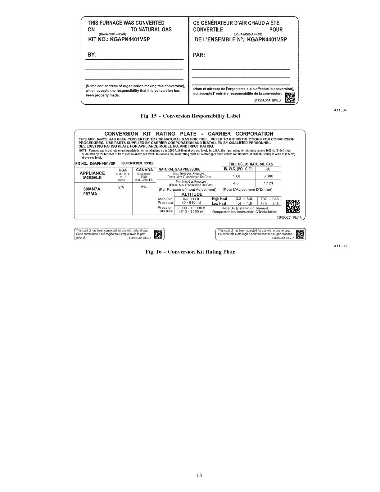
1. Fill in Conversion Responsibility Label 338305-205 and
apply to Blower Access Door of furnace as shown. (See
Fig. 15.) Date, name, and address of organization making
this conversion are required.
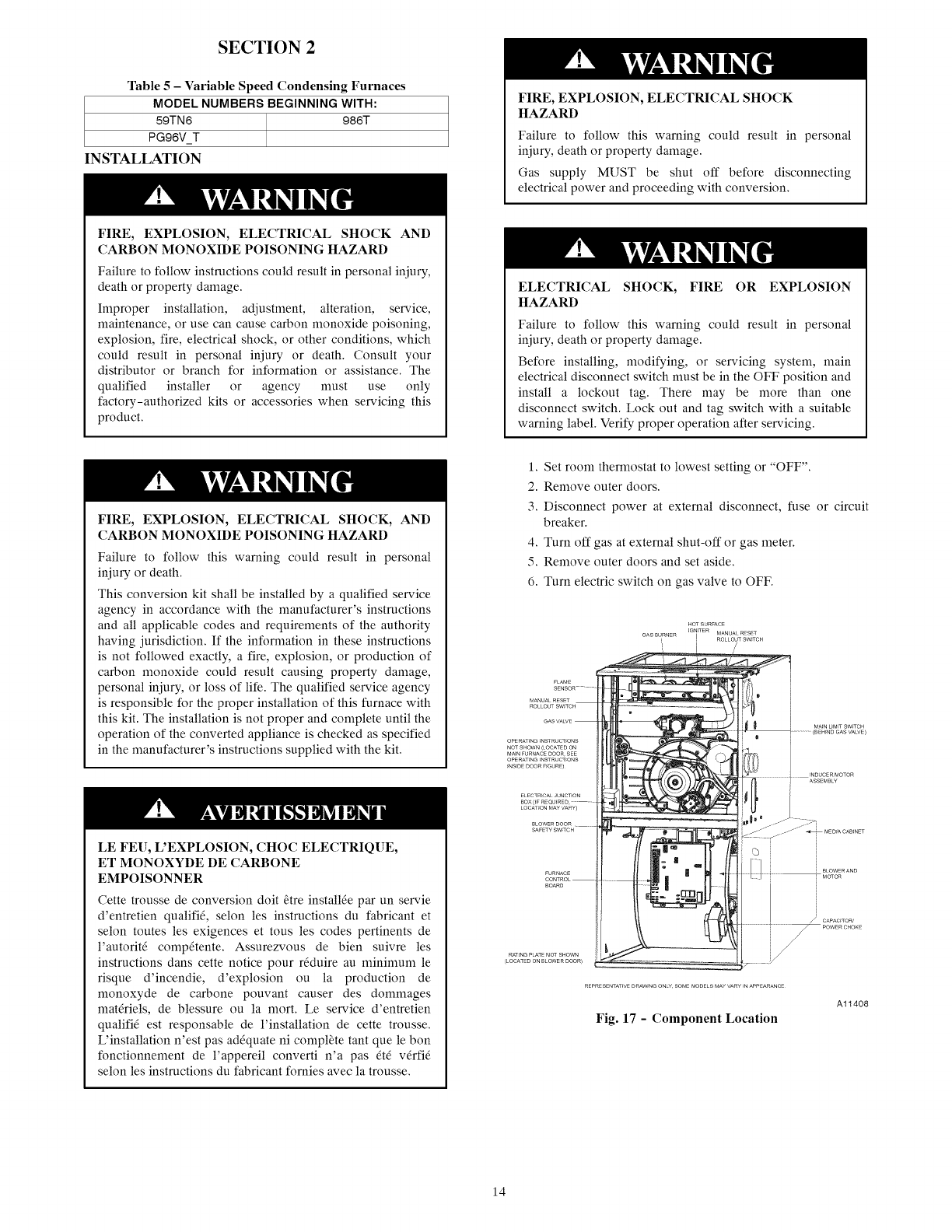
2. Attach Conversion Rating Plate Label 338305-201 to out-
er door of furnace, see Fig. 16.
3. Attach Gas Control Conversion Label 338305-202 to gas
valve. DO NOT use 338305-203, which is similar.
12
THiSFURNACEWAS CONVERTED
ON TO NATURALGAS
(DAY-MONTH-YEAR)
KiT NO.: KGAPN4401VSP
BY:
(Name and address of organization making this conversion),
which accepts the responsibility that this conversion has
been properly made.
CEG#NERATEURD'A[RCHAUDA _:TI_
CONVERTILE POUR
(JOUR-MOIS-ANNEE)
DE L'ENSEIVlBLEN°,: KGAPN4401VSP
PAR:
(Nora et adresse de I'organisrae qui a effectu_ Ja conversion),
qui accepte J' entri6re responsabiJit6 de Ja conversion.
338305-205 REV. A _'t._.
Fig. 15 - Conversion Responsibility Label
Al1504
CONVERSION KiT RATING PLATE -CARRIER CORPORATION
THiS APPLIANCE HAS BEEN CONVERTED TO USE NATURAL GAS FOR FUEL. REFER TO KiT iNSTRUCTiONS FOR CONVERSION
PROCEDURES. USE PARTS SUPPLIED BY CARRIER CORPORATION AND iNSTALLED BY QUALiFiED PERSONNEL.
SEE EXiSTiNG RATING PLATE FOR APPLIANCE MODEL NO. AND iNPUT RATING.
NOTE; Furnace gas input rate on rating plate is for instaJJationsup to 2000 ft. (010m) above sea [eveJ. in U.S.A. the input rating for altitudes above 2000 ft. (610m) must
be derated by 2% for each 1000 ft. (305m) above sea level In Canada the input rating must be derated (per chart below) for altitudes of 2000 ft. (010m) to 4500 ft. (1372m)
above sea Jevel.
IT NO,: KGAPN4401VSP (SUPERSEDES: NONE)
USA CANADA
APPLIANCE O/oDERATE % DERATE
MODELS PER FOR
1000 FT. 2000-4500 FT.
59MN7A 2% 5%
987MA
FUEL USED: NATURAL GAS
NATURAL GAS PRESSURE iN. W.C. (PO C.E.) P[ PA
Max. Inlet Gas Pressure
(Press. Max. D'Admission De Gaz) 13.6
Min. Inlet Gas Pressure
(Press, NJn, D'AdmJssion De Gaz) 4.5 1,121
(For Purpose of input Adjustment) (Pour L'Adjustment D'Entree)
ALTITUDE High Heat 3.2 -3.8
Manifold 0-2,000 ft. 797 - 946
Pressure (0 - 610 m) LOW Heat 1.4 - 1.8 349 - 448
Pression 2,000 - 10,000 ft. Refer to installation Manual
Tubu[ure (610 - 3050 ra) Respecter es nstructon D3nsta[[ation
338305-201 REV, A,
This control has been converted for use with natural gas. ]
Cette commande a et6 r6gl6e pour emploi avec le gaz _._ J
naturel. 338305-202 REV.A
This control has been adjusted for use with propane gas. I_,_ "}
Ce eoontrSle a et_ r6gl6e pour foneSonner au gaz propane, _/
330305-203 REV. A )
Fig. 16 - Conversion Kit Rating Plate
Al1503
13
SECTION 2
Table 5- Variable Speed Condensing Furnaces
MODEL NUMBERS BEGINNING WITH:
59TN6 986T
PG96V T
INSTALLATION
FIRE, EXPLOSION, ELECTRICAL SHOCK AND
CARBON MONOXIDE POISONING HAZARD
Failure to follow instructions could result in personal injury,
death or property damage.
Improper installation, adjustment, alteration, service,
maintenance, or use can cause carbon monoxide poisoning,
explosion, fire, electrical shock, or other conditions, which
could result in personal injury or death. Consult your
distributor or branch for information or assistance. The
qualified installer or agency nmst use only
factory-authorized kits or accessories when servicing this
product.
FIRE, EXPLOSION, ELECTRICAL SHOCK
HAZARD
Failure to follow this warning could result in personal
injury, death or property damage.
Gas supply MUST be shut off before disconnecting
electrical power and proceeding with conversion.
ELECTRICAL SHOCK, FIRE OR EXPLOSION
HAZARD
Failure to follow this warning could result in personal
injury, death or property damage.
Before installing, modifying, or servicing system, main
electrical disconnect switch nmst be in the OFF position and
install a lockout tag. There may be more than one
disconnect switch. Lock out and tag switch with a suitable
warning label. Verify proper operation after servicing.
FIRE, EXPLOSION, ELECTRICAL SHOCK, AND
CARBON MONOXIDE POISONING HAZARD
Failure to follow this warning could result in personal
injury or death.
This conversion kit shall be installed by a qualified service
agency in accordance with the manufacturer's instructions
and all applicable codes and requirements of the authority
having jurisdiction. If the information in these instructions
is not followed exactly, a fire, explosion, or production of
carbon monoxide could result causing property damage,
personal injury, or loss of life. The qualified service agency
is responsible for the proper installation of this furnace with
this kit. The installation is not proper and complete until the
operation of the converted appliance is checked as specified
in the manufacturer's instructions supplied with the kit.
LE FEU, L'EXPLOSION, CHOC ELECTRIQUE,
ET MONOXYDE DE CARBONE
EMPOISONNER
Cette trousse de conversion doit _tre install_e par un servie
d'entretien qualifid, selon les instructions du fabricant et
selon toutes les exigences et tous les codes pertinents de
l'autorit_ comp_tente. Assurezvous de bien suivre les
instructions dans cette notice pour rdduire au n_ininmm le
risque d'incendie, d'explosion ou la production de
monoxyde de carbone pouvant causer des dommages
matdriels, de blessure ou la mort. Le service d'entretien
qualifid est responsable de l'installation de cette trousse.
L'installation n'est pas adequate ni complete tant que le bon
fonctionnement de l'appereil converti n'a pas _td v_rfid
selon les instructions du fabricant fornies avec la trousse.
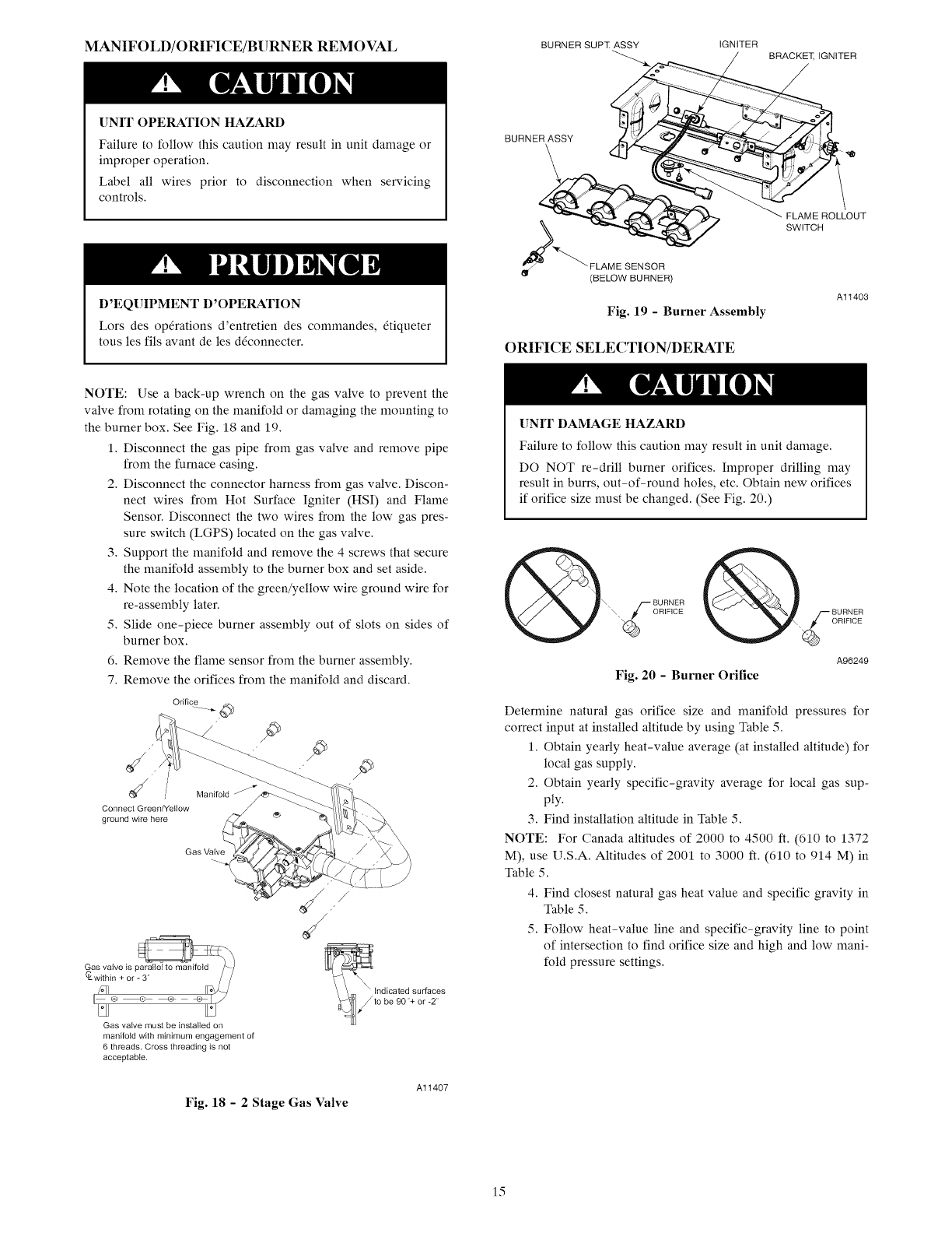
1. Set room thermostat to lowest setting or "OFF".
2. Remove outer doors.
3. Disconnect power at external disconnect, fuse or circuit
breaker.
4. Turn off gas at external shut-off or gas meter.
5. Remove outer doors and set aside.
6. Turn electric switch on gas valve to OFF.
FLAME
SENSOR ¸¸¸
MANUALRESET
ROLLOUTSW_TCH
GASVA_E
OPERATINGFNSTRUCT_ONS
NOTSHOWS(LOCATEDOS
MA_NFURNACEDOOR,SEE
OPERATINGFNSTRUCT_OSS
FNS_DEDOORFFGURE)
ELECTRICALJUSCT_ON
BOX (_F REQH_RED ....
LOCATION MAY VARY)
8LOWERDOOR.....
SAFETY SWFTC H
FURSACE
CONTROL
BOARD
RAT_NGPLATENOTSHOWS
(LOCATEDOSBLOWERDOOR)
©
BLOWERAND
q MOTOR
f CAPAC_TOR_
REPRESENTATIVEDRAWINGOSLYSOMEMODELSMAYVARY_NAPPEARANCE
Fig. 17 -Component Location
A11408
14
MANIFOLD/ORIFICE/BURNER REMOVAL
UNIT OPERATION HAZARD
Failure to follow this caution may result in unit damage or
improper operation.
Label all wires prior to disconnection when servicing
controls.
D'EQUIPMENT D'OPERATION
Lors des op6rations d'entretien des commandes, 6tiqueter
tousles ills avant de les d@onnecter.
BURNER SUPZ ASSY IGNITER
BURNER ASSY
_"'_ FLAM E SENSOR
(BELOW BURNER)
Fig. 19 - Burner Assembly
ORIFICE SELECTION/DERATE
BRACKET, IGNITER
/
FLAME ROLLOUT
SWITCH
Al1403
NOTE: Use a back-up wrench on the gas valve to prevent the
valve from rotating on the manifold or damaging the mounting to
the burner box. See Fig. 18 and 19.
1. Disconnect the gas pipe from gas valve and remove pipe
from the furnace casing.
2. Disconnect the connector harness from gas valve. Discon-
nect wires from Hot Surface Igniter (HSI) and Flame
Sensor. Disconnect the two wires from the low gas pres-
sure switch (LGPS) located on the gas valve.
3. Support the manifold and remove the 4 screws that secure
the manifold assembly to the burner box and set aside.
4. Note the location of the green/yellow wire ground wire for
re-assembly later.
5. Slide one-piece burner assembly out of slots on sides of
burner box.
6. Remove the flame sensor from the burner assembly.
7. Remove the orifices from the manifold and discard.
Orifice
d ¢ /
Connect Green/Yellow
ground wire here
Manifold S
Gas Valve
Gas valve must be installed on
manifold with minimum engagement of
6 threads. Cross threading is not
acceptable.
/
_lndicated sur[aces
!to be 90'+ or -2'
Fig. 18 - 2 Stage Gas Valve
Al1407
[]NIT DAMAGE HAZARD
Failure to follow this caution may result in unit damage.
DO NOT re-drill burner orifices. Improper drilling may
result in burrs, out-of-round holes, etc. Obtain new orifices
if orifice size must be changed. (See Fig. 20.)
A96249
Fig. 20 - Burner Orifice
Deternfine natural gas orifice size and manifold pressures for
correct input at installed altitude by using Table 5.
1. Obtain yearly heat-value average (at installed altitude) for
local gas supply.
2. Obtain yearly specific-gravity average for local gas sup-
ply.
3. Find installation altitude in Table 5.
NOTE: For Canada altitudes of 2000 to 4500 ft. (610 to 1372
M), use U.S.A. Altitudes of 2001 to 3000 ft. (610 to 914 M) in
Table 5.
4. Find closest natural gas heat value and specific gravity in
Table 5.
5. Follow heat-value line and specific-gravity line to point
of intersection to find orifice size and high and low mani-
fold pressure settings.
15
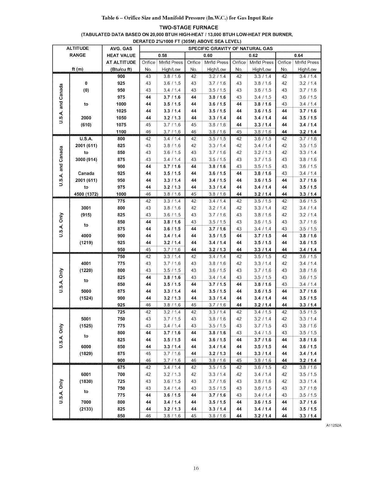
Table 6 - Orifice Size and Manifold Pressure (In.W.C.) for Gas Input Rate
TWO-STAGE FURNACE
(TABULATED DATA BASED ON 20,000 BTUH HIGH-HEAT /13,000 BTUH LOW-HEAT PER BURNER,
DERATED 2%/1000 FT (305M) ABOVE SEA LEVEL)
ALTITUDE AVG. GAS
RANGE HEAT VALUE 0.58 0.60
AT ALTITUDE Orifice Mnfld Press Orifice Mnfld Press
ft (m) _ No. Hi, h/Low No. Hi,h/Low
900 43 3.8 /1.6 42 3.2 /1.4
0925 43 3.6 /1.5 43 3.7 /1.6
(0) 950 43 3.4 /1.4 43 3.5 /1.5
c
o975 44 3.7 /1.6 44 3.8 /1.6
to 1000 44 3.5 /1.5 44 3.6 /1.5
<. 1025 44 3.3 /1.4 44 3.5 /1.5
u) 2000 1050 44 3.2 /1.3 44 3.3 /1.4
(610) 1075 45 3.7 /1.6 45 3.8 /1.6
1100 46 3.7 /1.6 46 3.8 /1.6
U.S.A. 800 42 3.4 /1.4 42 3.5 /1.5
2001 (611) 825 43 3.8 /1.6 42 3.3 /1.4
to 850 43 3.6 /1.5 43 3.7 /1.6
c
3000 (914) 875 43 3.4 /1.4 43 3.5 /1.5
900 44 3.7 /1.6 44 3.8 /1.6
Canada 925 44 3.5 /1.5 44 3.6 /1.5
u_ 2001 (611) 950 44 3.3 /1.4 44 3.4 /1.5
to 975 44 3.2 /1.3 44 3.3 /1.4
__ 1000 46 3.8 /1.6 45 3.8 /1.6
775 42 3.3 /1.4 42 3.4 /1.4
3001 800 43 3.8 /1.6 42 3.2 /1.4
--_ (915) 825 43 3.6 /1.5 43 3.7 /1.6
c
O 850 44 3.8 /1.6 43 3.5 /1.5
to 875 44 3.6 /1.5 44 3.7 /1.6
4000 900 44 3.4 /1.4 44 3.5 /1.5
(1219) 925 44 3.2 /1.4 44 3.4 /1.4
950 45 3.7 /1.6 44 3.2 /1.3
750 42 3.3 /1.4 42 3.4 /1.4
4001 775 43 3.7 /1.6 43 3.8 /1.6
--_ (1220) 800 43 3.5 /1.5 43 3.6 /1.5
c
O 825 44 3.8 /1.6 43 3.4 /1.4
to 850 44 3.5 /1.5 44 3.7 /1.5
5000 875 44 3.3 /1.4 44 3.5 /1.5
(1524) 900 44 3.2 /1.3 44 3.3 /1.4
925 46 3.8 /1.6 45 3.7 /1.6
725 42 3.2 /1.4 42 3.3 /1.4
5001 750 43 3.7 /1.5 43 3.8 /1.6
--_ (1525) 775 43 3.4 /1.4 43 3.5 /1.5
c
O 800 44 3.7 /1.6 44 3.8 /1.6
to 825 44 3.5 /1.5 44 3.6 /1.5
6000 850 44 3.3 /1.4 44 3.4 /1.4
(1829) 875 45 3.7 /1.6 44 3.2 /1.3
900 46 3.7 /1.6 46 3.8 /1.6
675 42 3.4 /1.4 42 3.5 /1.5
6001 700 42 3.2 /1.3 42 3.3 /1.4
--_ (1830) 725 43 3.6 /1.5 43 3.7 /1.6
c
O750 43 3.4 /1.4 43 3.5 /1.5
<" to 775 44 3.6 /1.5 44 3.7 /1.6
u) 7000 800 44 3.4 /1.4 44 3.5 /1.5
(2133) 825 44 3.2 /1.3 44 3.3 /1.4
850 46 3.8 /1.6 45 3.8 /1.6
SPECIFIC GRAVITY OF NATURAL GAS
0.62
Orifice Mnfld Press
No.
42 3.3 /1.4
43 3.8 /1.6
43 3.6 /1.5
43 3.4 /1.5
44 3.8 /1.6
44 3.6 /1.5
44 3.4 /1.4
44 3.3 /1.4
45 3.8 /1.6
42 3.6 /1.5
42 3.4 /1.4
42 3.2 /1.3
43 3.7 /1.5
43 3.5 /1.5
44 3.8 /1.6
44 3.6 /1.5
44 3.4 /1.4
44 3.2 /1.4
42 3.5 /1.5
42 3.3 /1.4
43 3.8 /1.6
43 3.6 /1.5
43 3.4 /1.4
44 3.7 /1.5
44 3.5 /1.5
44 3.3 /1.4
42 3.5 /1.5
42 3.3 /1.4
43 3.7 /1.6
43 3.5 /1.5
44 3.8 /1.6
44 3.6 /1.5
44 3.4 /1.4
44 3.2 /1.4
42 3.4 /1.5
42 3.2 /1.4
43 3.7 /1.5
43 3.4 /1.5
44 3.7 /1.6
44 3.5 /1.5
44 3.3 /1.4
45 3.8 /1.6
42 3.6 /1.5
42 3.4 /1.4
43 3.8 /1.6
43 3.6 /1.5
43 3.4 /1.4
44 3.6 /1.5
44 3.4 /1.4
44 3.2 /1.4
0.64
Orifice Mnfld Press
No. Hi_htLow
42 3.4 /1.4
42 3.2 /1.4
43 3.7 /1.6
43 3.6 /1.5
43 3.4 /1.4
44 3.7 /1.6
44 3.5 /1.5
44 3.4 /1.4
44 3.2 /1.4
42 3.7 /1.6
42 3.5 /1.5
42 3.3 /1.4
43 3.8 /1.6
43 3.6 /1.5
43 3.4 /1.4
44 3.7 /1.6
44 3.5 /1.5
44 3.3 /1.4
42 3.6 /1.5
42 3.4 /1.4
42 3.2 /1.4
43 3.7 /1.6
43 3.5 /1.5
44 3.8 /1.6
44 3.6 /1.5
44 3.4 /1.4
42 3.6 /1.5
42 3.4 /1.4
43 3.8 /1.6
43 3.6 /1.5
43 3.4 /1.4
44 3.7 /1.6
44 3.5 /1.5
44 3.3 /1.4
42 3.5 /1.5
42 3.3 /1.4
43 3.8 /1.6
43 3.5 /1.5
44 3.8 /1.6
44 3.6 /1.5
44 3.4 /1.4
44 3.2 /1.4
42 3.8 /1.6
42 3.5 /1.5
42 3.3 /1.4
43 3.7 /1.6
43 3.5 /1.5
44 3.7 /1.6
44 3.5 /1.5
44 3.3 /1.4
Al1252A
ld
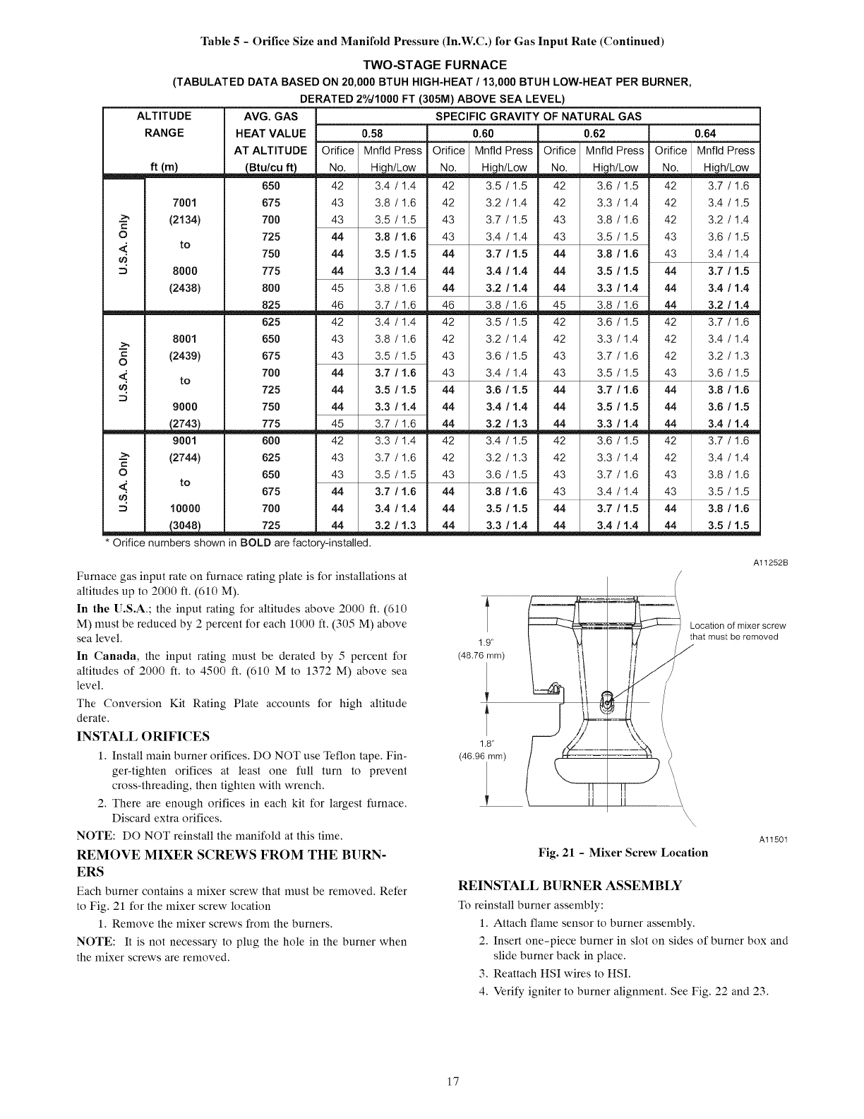
Table 5 - Orifice Size and Manifold Pressure (In.W.C.) for Gas Input Rate (Continued)
TWO-STAGE FURNACE
(TABULATED DATA BASED ON 20,000 BTUH HIGH-HEAT/13,000 BTUH LOW-HEAT PER BURNER,
DERATED 2%/1000 FT (305M) ABOVE SEA LEVEL)
ALTITUDE AVG. GAS
RANGE HEAT VALUE 0.58
AT ALTITUDE Orifice Mnfld Press
ft (m) _ No_,, ,,,,,_h/Low
650
7001 675
--_ (2134) 700
O 725
<' to 750
8000 775
(2438) 800
825
625
8001 650
c(2439) 675
O
<.' to 700
_. 725
9000 750
__ 775
9001 600
--_ (2744) 625
O 650
<' to 675
10000 700
* Orifice numbers shown in BOLD are factory-installed.
SPECIFIC GRAVITY OF NATURAL GAS
0.60 0.62
Orifice Mnfld Press Orifice Mnfld Press
No. Hi,h/Low No. Hi,h/Low
42 3.4 /1.4 42 3.5 /1.5 42 3.6 /1.5
43 3.8 /1.6 42 3.2 /1.4 42 3.3 /1.4
43 3.5 /1.5 43 3.7 /1.5 43 3.8 /1.6
44 3.8 /1.6 43 3.4 /1.4 43 3.5 /1.5
44 3.5 /1.5 44 3.7 /1.5 44 3.8 /1.6
44 3.3 /1.4 44 3.4 /1.4 44 3.5 /1.5
45 3.8 /1.6 44 3.2 /1.4 44 3.3 /1.4
46 3.7 /1.6 46 3.8 /1.6 45 3.8 /1.6
42 3.4 /1.4 42 3.5 /1.5 42 3.6 /1.5
43 3.8 /1.6 42 3.2 /1.4 42 3.3 /1.4
43 3.5 /1.5 43 3.6 /1.5 43 3.7 /1.6
44 3.7 /1.6 43 3.4 /1.4 43 3.5 /1.5
44 3.5 /1.5 44 3.6 /1.5 44 3.7 /1.6
44 3.3 /1.4 44 3.4 /1.4 44 3.5 /1.5
45 3.7 /1.6 44 3,2 /1,3 44 3,3 /1,4
42 3.3 /1.4 42 3.4 /1.5 42 3.6 /1.5
43 3.7 /1.6 42 3.2 /1.3 42 3.3 /1.4
43 3.5 /1.5 43 3.6 /1.5 43 3.7 /1.6
44 3.7 /1.6 44 3.8 /1.6 43 3.4 /1.4
44 3.4 /1.4 44 3.5 /1.5 44 3.7 /1.5
3.4 /1.4
0.64
Orifice Mnfld Press
No. Hi2h/Low
42 3.7 /1.6
42 3.4 /1.5
42 3.2 /1.4
43 3.6 /1.5
43 3.4 /1.4
44 3.7 /1.5
44 3.4 /1.4
44 3.2 /1.4
42 3.7 /1.6
42 3.4 /1.4
42 3.2 /1.3
43 3.6 /1.5
44 3.8 /1.6
44 3.6 /1.5
44 3.4 /1.4
42 3.7 /1.6
42 3.4 /1.4
43 3.8 /1.6
43 3.5 /1.5
44 3.8 /1.6
44 3.5 /1.5
Furnace gas input rate on furnace rating plate is for installations at
altitudes up to 2000 ft. (610 M).
In the U.S.A.; the input rating for altitudes above 2000 ft. (610
M) must be reduced by 2 percent for each 1000 ft. (305 M) above
sea level.
In Canada, the input rating must be derated by 5 percent for
altitudes of 2000 ft. to 4500 ft. (610 M to 1372 M) above sea
level.
The Conversion Kit Rating Plate accounts for high altitude
derate.
INSTALL ORIFICES
1. Install main burner orifices. DO NOT use Teflon tape. Fin-
ger-tighten orifices at least one full turn to prevent
cross-threading, then tighten with wrench.
2. There are enough orifices in each kit for largest furnace.
Discard extra orifices.
NOTE: DO NOT reinstall the manifold at this time.
REMOVE MIXER SCREWS FROM THE BURN-
ERS
Each burner contains a mixer screw that must be removed. Refer
to Fig. 21 for the mixer screw location
1. Remove the mixer screws from the burners.
NOTE: It is not necessary to plug the hole in the burner when
the mixer screws are removed.
Al1252B
1.9"
(48.76 mm)
t
1.8"
(46.96 mm)
(\11
Location of mixer screw
..._hat must be removed
\\\\
Al1501
Fig. 21 - Mixer Screw Location
REINSTALL BURNER ASSEMBLY
To reinstall burner assembly:
1. Attach flame sensor to burner assembly.
2. Insert one-piece burner in slot on sides of burner box and
slide burner back in place.
3. Reattach HSI wires to HSI.
4. Verify igniter to burner alignment. See Fig. 22 and 23.
17
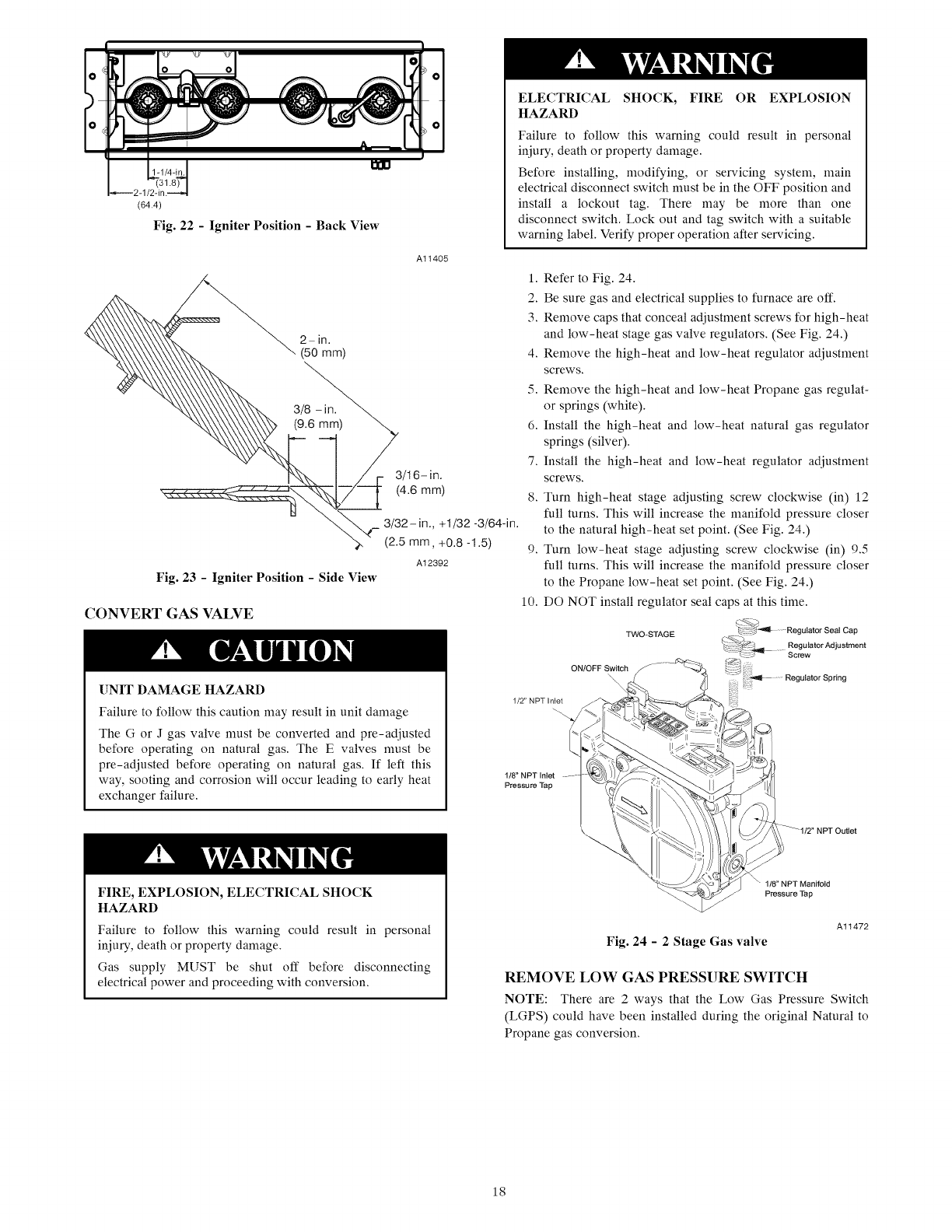
ql !
(64.4)
Fig. 22 -Igniter Position - Back View
Al1405
2- irl.
(50 mm)
3/16- in.
(4.6 mm)
r3/32 -in., +1/32 -3/64-in.
(2.5 mm, +0.8 -1.5)
A12392
Fig. 23 -Igniter Position - Side View
CONVERT GAS VALVE
[]NIT DAMAGE HAZARD
Failure to follow this caution may result in unit damage
The G or J gas valve must be converted and pre-adjusted
before operating on natural gas. The E valves must be
pre-adjusted before operating on natural gas. If left this
way, sooting and corrosion will occur leading to early heat
exchanger failure.
ELECTRICAL SHOCK, FIRE OR EXPLOSION
HAZARD
Failure to follow this warning could result in personal
injury, death or property damage.
Before installing, modifying, or servicing system, main
electrical disconnect switch must be in the OFF position and
install a lockout tag. There may be more than one
disconnect switch. Lock out and tag switch with a suitable
warning label. Verify proper operation after servicing.
1. Refer to Fig. 24.
2. Be sure gas and electrical supplies to furnace are off.
3. Remove caps that conceal adjustment screws for high-heat
and low-heat stage gas valve regulators. (See Fig. 24.)
4. Remove the high-heat and low-heat regulator adjustment
screws.
5. Remove the high-heat and low-heat Propane gas regulat-
or springs (white).
6. Install the high-heat and low-heat natural gas regulator
springs (silver).
7. Install the high-heat and low-heat regulator adjustment
screws.
8. Turn high-heat stage adjusting screw clockwise (in) 12
full turns. This will increase the manifold pressure closer
to the natural high-heat set point. (See Fig. 24.)
9. Turn low-heat stage adjusting screw clockwise (in) 95
full turns. This will increase the manifold pressure closer
to the Propane low-heat set point. (See Fig. 24.)
10. DO NOT install regulator seal caps at this time.
') "_ Regulator Seal Cap
TWO-STAGE _ _@_ 9 *
_ _= Regulator Ad ustment
1-: _ ..... Screw
ON/OFF Switch
1/2" NPT Inlet
1/8" NPT Inlet
Pressure Tap
FIRE, EXPLOSION, ELECTRICAL SHOCK
HAZARD
Failure to follow this warning could result in personal
injury, death or property damage.
Gas supply MUST be shut off before disconnecting
electrical power and proceeding with conversion.
1t8" NPT Manifold
Pressure Tap
Fig. 24 - 2 Stage Gas valve
Al1472
REMOVE LOW GAS PRESSURE SWITCH
NOTE: There are 2 ways that the Low Gas Pressure Switch
(LGPS) could have been installed during the original Natural to
Propane gas conversion.
18
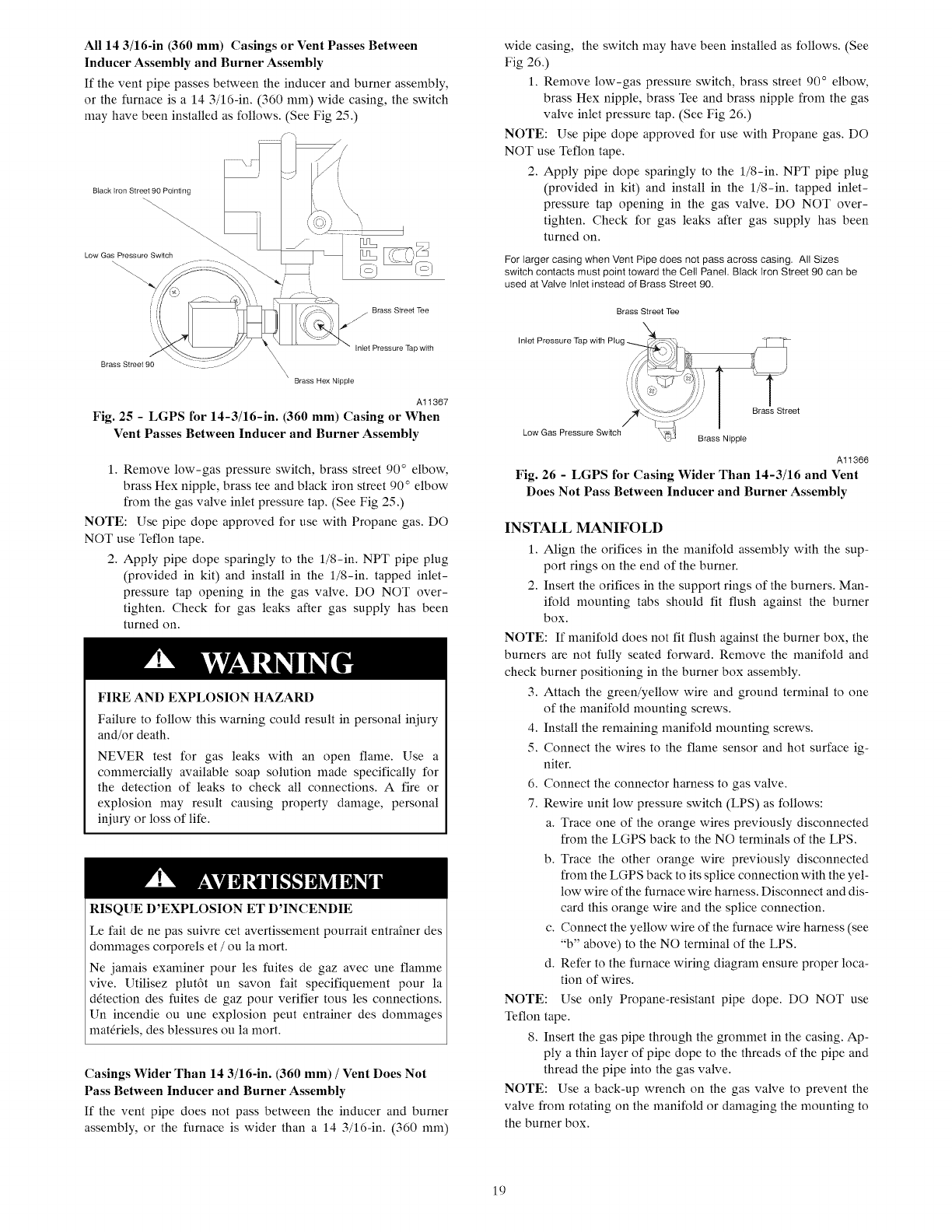
All143/16-in (360 mm) Casings or Vent Passes Between
Inducer Assembly and Burner Assembly
If the vent pipe passes between the inducer and burner assembly,
or the furnace is a 14 3/16-in. (360 ram) wide casing, the switch
may have been installed as follows. (See Fig 25.)
Brass Hex Nipple
A11367
Fig. 25 - LGPS for 14-3/16-in. (360 mm) Casing or When
Vent Passes Between Inducer and Burner Assembly
1. Remove low-gas pressure switch, brass street 90 ° elbow,
brass Hex nipple, brass tee and black iron street 90 ° elbow
from the gas valve inlet pressure tap. (See Fig 25.)
NOTE: Use pipe dope approved for use with Propane gas. DO
NOT use Teflon tape.
2. Apply pipe dope sparingly to the l/8-in. NPT pipe plug
(provided in kit) and install in the l/8-in, tapped inlet-
pressure tap opening in the gas valve. DO NOT over-
tighten. Check for gas leaks after gas supply has been
turned on.
FIRE AND EXPLOSION HAZARD
Failure to follow this warning could result in personal injury
and/or death.
NEVER test for gas leaks with an open flame. Use a
commercially available soap solution made specifically for
the detection of leaks to check all connections. A fire or
explosion may result causing property damage, personal
injury or loss of life,
RISQUE D'EXPLOSION ET D'INCENDIE
Le fait de ne pas suivre cet avertissement pourrait entra_ner des
dommages corporels et /ou la mort.
Ne jamais examiner pour les fuites de gaz avec une flamme
vive. Utilisez plut6t un savon fair specifiquement pour la
d_tection des fuites de gaz pour verifier tousles connections.
Un incendie ou une explosion peut entrainer des dommages
materiels, des blessures ou la mort.
Casings Wider Than 14 3/16-in. (360 mm) /Vent Does Not
Pass Between Inducer and Burner Assembly
If the vent pipe does not pass between the inducer and burner
assembly, or the furnace is wider than a 14 3/16-in. (360 ram)
wide casing, the switch may have been installed as follows. (See
Fig 260
1. Remove low-gas pressure switch, brass street 90 ° elbow,
brass Hex nipple, brass Tee and brass nipple from the gas
valve inlet pressure tap. (See Fig 26.)
NOTE: Use pipe dope approved for use with Propane gas. DO
NOT use Teflon tape.
2. Apply pipe dope sparingly to the l/8-in. NPT pipe plug
(provided in kit) and install in the l/8-in, tapped inlet-
pressure tap opening in the gas valve. DO NOT over-
tighten. Check for gas leaks after gas supply has been
turned on.
For larger casing when Vent Pipe does not pass across casing. All Sizes
switch contacts must point toward the Cell Panel. Black Iron Street 90 can be
used at Valve Inlet instead of Brass Street 90.
Brass Street Tee
Inlet Pressure Tap with Plug " "
Low Gas Pressure Switch \2i_ ; Brass Nipple
Brass Street
A11366
Fig. 26 - LGPS for Casing Wider Than 14-3/16 and Vent
Does Not Pass Between Inducer and Burner Assembly
INSTALL MANIFOLD
1. Align the orifices in the manifold assembly with the sup-
port rings on the end of the burner.
2. Insert the orifices in the support rings of the burners. Man-
ifold mounting tabs should fit flush against the burner
box.
NOTE: If manifold does not fit flush against the burner box, the
burners are not fully seated forward. Remove the manifold and
check burner positioning in the burner box assembly.
3. Attach the green/yellow wire and ground terminal to one
of the manifold mounting screws.
4. Install the remaining manifold mounting screws.
5. Connect the wires to the flame sensor and hot surface ig-
niter.
6. Connect the connector harness to gas valve.
7. Rewire unit low pressure switch (LPS) as follows:
a. Trace one of the orange wires previously disconnected
from the LGPS back to the NO terminals of the LPS.
b. Trace the other orange wire previously disconnected
from the LGPS back to its splice connection with the yel-
low wire of the furnace wire harness. Disconnect and dis-
card this orange wire and the splice connection.
c. Connect the yellow wire of the furnace wire harness (see
"b" above) to the NO terminal of the LPS.
d. Refer to the furnace wiring diagram ensure proper loca-
tion of wires.
NOTE: Use only Propane-resistant pipe dope, DO NOT use
Teflon tape.
8. Insert the gas pipe through the grommet in the casing. Ap-
ply a thin layer of pipe dope to the threads of the pipe and
thread the pipe into the gas valve.
NOTE: Use a back-up wrench on the gas valve to prevent the
valve from rotating on the manifold or damaging the mounting to
the burner box.
19
9. Withaback-upwrenchonthe inlet boss of the gas valve,
finish tightening the gas pipe to the gas valve.
10. Turn gas on at electric switch on gas valve.
CHECK INLET GAS PRESSURE
UNIT DAMAGE HAZARD
Failure to follow this caution may result in unit damage.
DO NOT operate furnace more than one minute to check
inlet gas pressure, as conversion is not complete at this time.
NOTE: This kit is to be used only when inlet gas pressure is
between 4.5-in. W.C. and 13.6-in. W.C.
1. Verify manometer is connected to inlet pressure tap on gas
valve.
2. Turn on furnace power supply.
3. Turn gas supply manual shutoff valve to ON position.
4. Turn furnace gas valve switch to ON position.
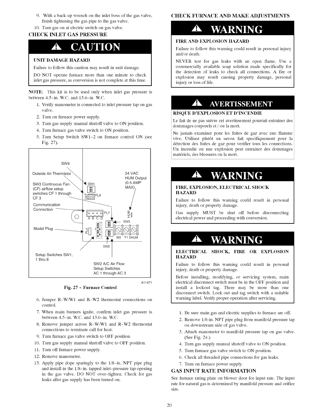
5. Turn Setup Switch SWI-2 on furnace control ON (see
Fig. 27).
SW4
Outside Air Thermistor_
_F_ CrflnotiwnU;_uSpFan_
switches CF 1 through
CF 3 "_
Communication
SW4
[]
_I=_ PLB
O_
Connecton--
24 VAC
HUM Output
(O.5AMP
i
Setup Switches SWl,
1 thru 8
[_ SW3
Model Plug _ _-N _!:i _]_
Z"_ /_:21 _ W2 Yt DHUM
SW2
I
SW2 A/C Air Flow
Setup Switches
AC 1 through AC 3
Fig. 27 -Furnace Control
Al1471
6. Jumper R-W/W1 and R-W2 thermostat connections on
control.
7. When main burners ignite, confirm inlet gas pressure is
between 4.5-in. W.C. and 13.6-in. W.C.
8. Remove jumper across R-W/WI and R-W2 thermostat
connections to terminate call for heat.
9. Turn furnace gas valve switch to OFF position.
10. Turn gas supply manual shutoff valve to OFF position.
11. Turn off furnace power supply.
12. Remove manometer.
13. Apply pipe dope sparingly to the l/8-in. NPT pipe plug
and install in the l/8-in, tapped inlet-pressure tap opening
in the gas valve. DO NOT over-tighten. Check for gas
leaks after gas supply has been turned on.
CHECK FURNACE AND MAKE ADJUSTMENTS
FIRE AND EXPLOSION HAZARD
Failure to follow this warning could result in personal iniury
and/or death.
NEVER test for gas leaks with an open flame. Use a
commercially available soap solution made specifically for
the detection of leaks to check all connections. A fire or
explosion may result causing property damage, personal
iniury or loss of life.
RISQUE D'EXPLOSION ET D'INCENDIE
Le fair de ne pas suivre cet avertissement pourrait entra_ner des
dommages corporels et /ou la mort.
Ne jamais examiner pour les fuites de gaz avec une flamme
vive. Utilisez plut6t un savon fair specifiquement pour la
d6tection des fuites de gaz pour verifier tousles connections.
Un incendie ou une explosion peut entrainer des dommages
mat6riels, des blessures ou la mort.
FIRE, EXPLOSION, ELECTRICAL SHOCK
HAZARD
Failure to follow this warning could result in personal
iniury, death or property damage.
Gas supply MUST be shut off before disconnecting
electrical power and proceeding with conversion.
ELECTRICAL SHOCK, FIRE OR EXPLOSION
HAZARD
Failure to follow this warning could result in personal
iniury, death or property damage.
Before installing, modifying, or servicing system, main
electrical disconnect switch must be in the OFF position and
install a lockout tag. There may be more than one
disconnect switch. Lock out and tag switch with a suitaMe
warning label. Verify proper operation after servicing.
1. Be sure main gas and electric supplies to furnace are off.
2. Remove l/8-in. NPT pipe plug from manifold pressure tap
on downstream side of gas valve.
3. Attach manometer to manih_ld pressure tap on gas valve.
(See Fig. 24.)
4. Turn gas supply manual shutoff valve to ON position.
5. Turn furnace gas valve switch to ON position.
6. Check all threaded pipe connections for gas leaks.
7. Turn on furnace power supply.
GAS INPUT RATE INFORMATION
See furnace rating plate on blower door for input rate. The input
rate for natural gas is determined by manifold pressure and orifice
size.
20
Deternfinenaturalgasorificesizeandmanifoldpressuresfor
correctinputatinstalledaltitudebyusingTable5.
1.Obtainyearlyheat-valueaverage(atinstalledaltitude)for
localgassupply.
2.Obtainyearlyspecific-gravityaverageforlocalgassup-
ply.
3.FindinstallationaltitudeinTable5.
NOTE:ForCanadaaltitudesof2000to4500ft.(610to1372
M),useU.S.A.Altitudesof2001to3000ft.(610to914M)in
Table5.
Furnacegasinputrateonratingplateisfor installationsat
altitudesupto2000ft.(610M).
IntheU.S.A.,theinputratingforaltitudesabove2000ft.(610M)
mustbereducedby2percentforeach1000ft.(305M)abovesea
level.
In Canada,theinputratingmustbederatedby5percentfor
altitudesof 2000ft.(610M)to4500ft. (1372M)abovesea
level.
TheConversionKit RatingPlateaccountsfor highaltitude
derate.
SETGASINPUTRATE
1.Makesurethegassupplyisturnedofftothefurnaceand
attheelectricswitchonthegasvalve.
2.Removethe1/8inchNPTplugfromtheoutletpressure
taponthegasvalve.
3.Connectamanometertotheoutletpressuretapongas
valve.
4.Turnonfurnacepowersupply.
5.TurngassupplymanualshutoffvalvetoONposition.
6.TurnfurnacegasvalveswitchtoONposition.
7.VerifySWI-2onfurnacecontrolisturned"ON".
8.JumperRandW/WIthermostatconnectionstocallfor
heat.
9.Checkmanifoldorificesforgasleakswhenmainburners
ignite.
10.Adjustgasmanifoldpressure.RefertoTable5.
11.Removecapsthatconcealtheadjustmentscrewsforgas
valveregulators.SeeFig.24.
12.Adjustlow-heatmanifoldpressurefornaturalgas.See
Fig.24.
13.Turnlow-heatadjustingscrewcounterclockwise(out)to
decreaseinputrateorclockwise(in)toincreaseinputrate.
NOTE:Whencorrectinputis obtained,mainburnerflame
shouldbeclearblue,almosttransparent(seeFig.28).
14.JumperR,W/WIandW2oncontrolcenterthermostat
connections.Thiskeepsfurnacelockedinhigh-heatoper-
ation.
15.Adjusthigh-heatmanifoldpressurefornaturalgas.
16.Turnhigh-heatadjustingscrewcounterclockwise(out)to
decreaseinputrateorclockwise(in)toincreaseinputrate.
17.Replacecapsthatconcealthegasvalveregulatoradjust-
mentscrews.
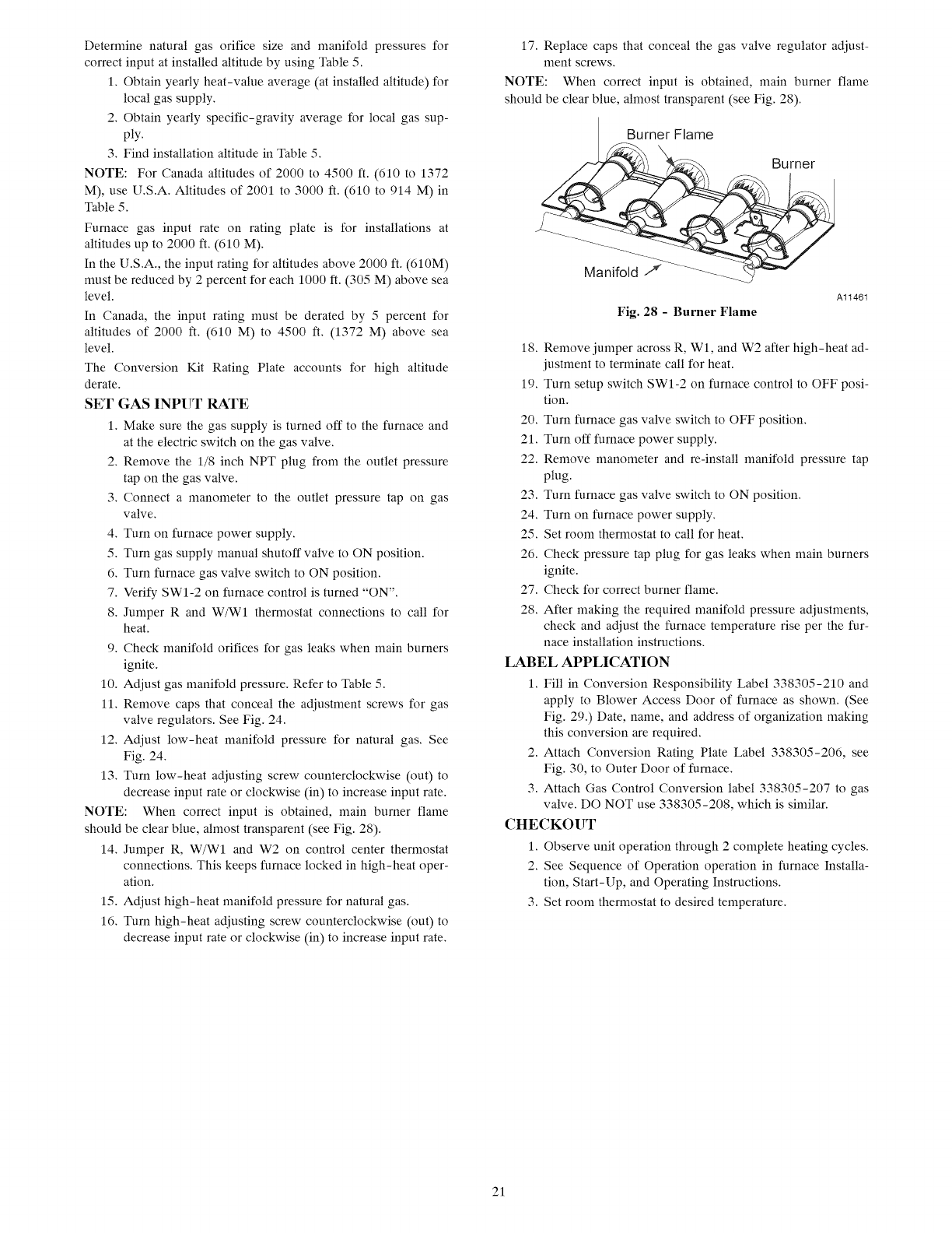
NOTE:Whencorrectinputis obtained,mainburnerflame
shouldbeclearblue,almosttransparent(seeFig.28).
Burner Flame
_/_ Burner
Al1461
Fig. 28 - Burner Flame
18. Remove jumper across R, Wl, and W2 after high-heat ad-
justment to ternfinate call for heat.
19. Turn setup switch SWI-2 on furnace control to OFF posi-
tion.
20. Turn furnace gas valve switch to OFF position.
21. Turn off furnace power supply.
22. Remove manometer and re-install manifold pressure tap
plug.
23. Turn furnace gas valve switch to ON position.
24. Turn on furnace power supply.
25. Set room thermostat to call for heat.
26. Check pressure tap plug for gas leaks when main burners
ignite.
27. Check for correct burner flame.
28. After making the required manifold pressure adjustments,
check and adjust the furnace temperature rise per the fur-
nace installation instructions.
LABEL APPLICATION
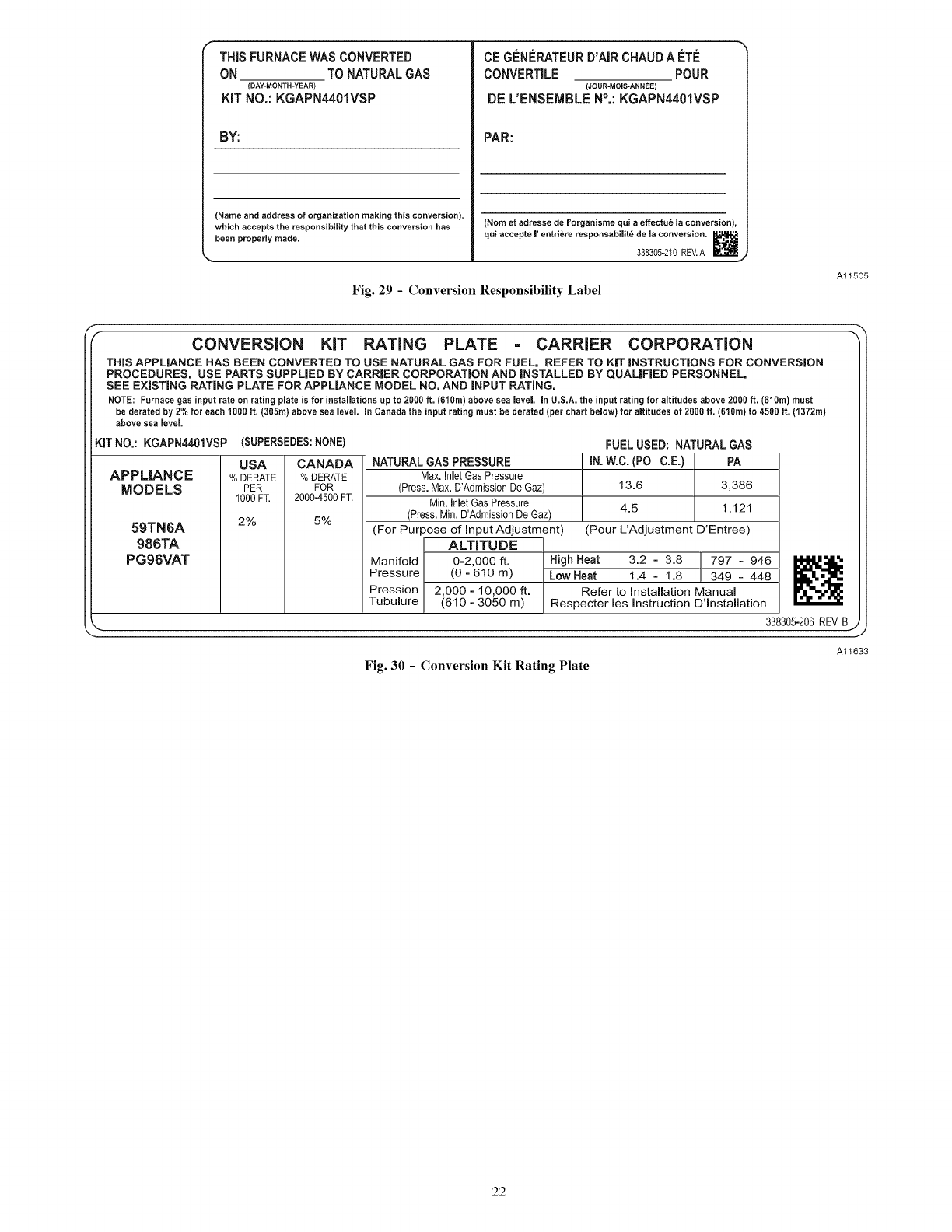
1. Fill in Conversion Responsibility Label 338305-210 and
apply to Blower Access Door of furnace as shown. (See
Fig. 29.) Date, name, and address of organization making
this conversion are required.
2. Attach Conversion Rating Plate Label 338305-206, see
Fig. 30, to Outer Door of furnace.
3. Attach Gas Control Conversion label 338305-207 to gas
valve. DO NOT use 338305-208, which is sinfilar.
CHECKOUT
1. Observe unit operation through 2 complete heating cycles.
2. See Sequence of Operation operation in furnace Installa-
tion, Start-Up, and Operating Instructions.
3. Set room thermostat to desired temperature.
21
THiSFURNACEWAS CONVERTED
ON TO NATURALGAS
(DAY-MONTH-YEAR)
KiT NO.: KGAPN4401VSP
BY:
(Name and address of organization making this conversion),
which accepts the responsibility that this conversion has
been properly made.
CEGI_NI_RATEURD'AIRCHAUDA ETI_
CONVERTILE POUR
(JOUR-MOIS-ANNEE)
DE L'ENSEIVlBLEN°,: KGAPN4401VSP
PAR:
(Nora et adresse de I'organisme qui a effectu6 la conversion),
qui accepte |' entri6re responsabilit6 de la conversion.
338305-210 REV.A _.j
Fig. 29 - Conversion Responsibility Label
Al1505
CONVERSION KiT RATING PLATE CARRIER CORPORATION
THiS APPLIANCE HAS BEEN CONVERTED TO USE NATURAL GAS FOR FUEL, REFER TO KiT iNSTRUCTiONS FOR CONVERSION
PROCEDURES, USE PARTS SUPPLIED BY CARRIER CORPORATION AND iNSTALLED BY QUALiFiED PERSONNEL,
SEE EXISTING RATING PLATE FOR APPLIANCE MODEL NO, AND iNPUT RATING,
NOTE: Furnacegas inputrate on rating plate is for installationsup to 2000ft. (6t0m) above sea level in U.S.A.the input rating for altitudesabove2000ft. (610m)must
be deratedby 2%for each 1000ft. (305m)abovesea level, inCanadathe inputrating must be derated(per chart below) for altitudesof 2000ft. (610m)to 4500 ft. (1372m)
above sea level
KITNO,: KGAPN4401VSP (SUPERSEDES:NONE)
USA CANADA
APPLIANCE % BERATE %BERATE
MODELS PER FOR
1000 FT. 2000=4500FT.
2% 5%
59TN6A
986TA
PG96VAT
NATURAL GAS PRESSURE
Max. InletGas Pressure
(Press. Max. D'Admission De Gaz)
Min. inletGas Pressure
(Press. Min. D'Admission De Gaz)
(For Purpose of input Adjustment)
ALTITUDE
FUEL USED: NATURAL GAS
iN. W.C. (PO C.E.) PA
13.6 3,386
4.5 1,121
(Pour L'Adjustment D'Entree)
Manifold 0=2,000 ft. High Heat 3.2 - 3.8 /797 - 946 _1_1_.
Pressure (0 - 610 m) Low Heat 1.4 - 1.8 [ 349 - 448
Pression 2,000 - 10,000 ft. Refer to Installation Manual
Tubulure (610 - 3050 m) Respecter les instruction D'lnstallation
_. 338305-206 REV.B
Al1633
Fig. 30 - Conversion Kit Rating Plate
22
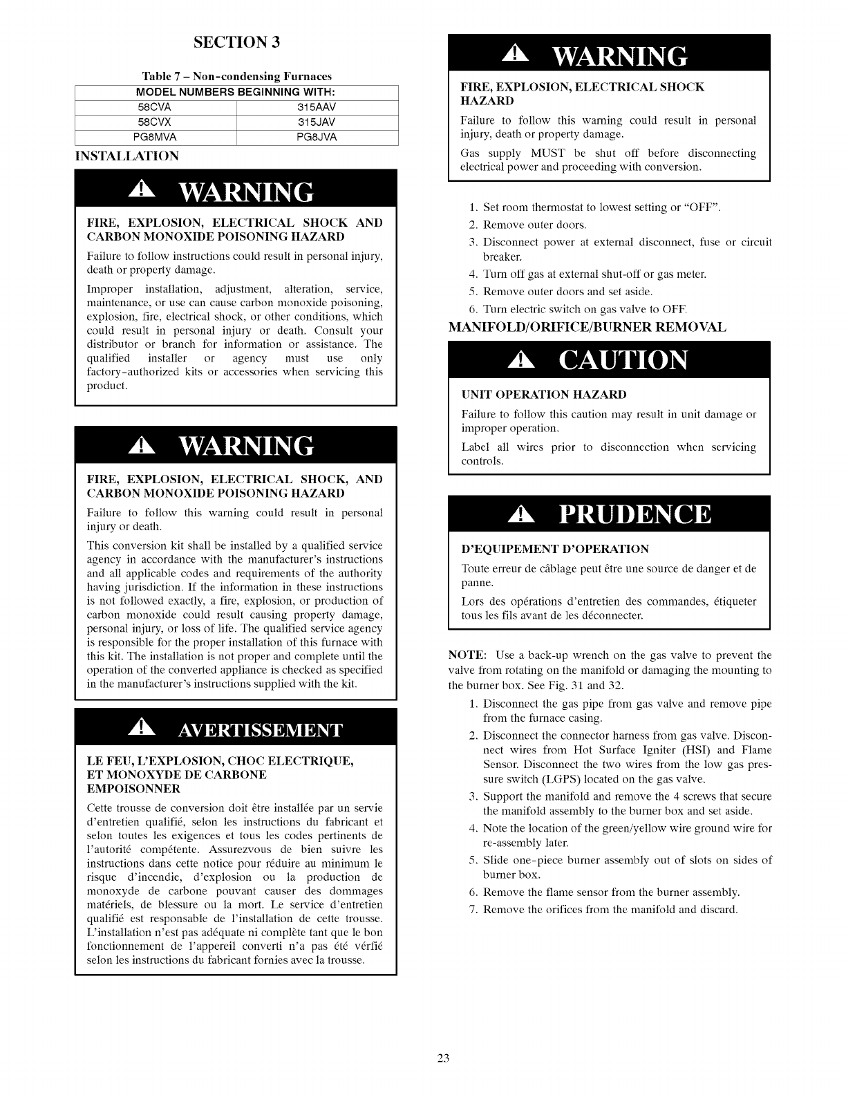
SECTION 3
Table 7-Non-condensing Furnaces
MODEL NUMBERS BEGINNING WITH:
58CVA 315AAV
58CVX 315JAV
PG8MVA PG8JVA
INSTALLATION
FIRE, EXPLOSION, ELECTRICAL SHOCK
HAZARD
Failure to follow this warning could result in personal
iniury, death or property damage.
Gas supply MUST be shut off before disconnecting
electrical power and proceeding with conversion.
FIRE, EXPLOSION, ELECTRICAL SHOCK AND
CARBON MONOXIDE POISONING HAZARD
Failure to follow instructions could result in personal injury,
death or property damage.
Improper installation, adjustment, alteration, service,
maintenance, or use can cause carbon monoxide poisoning,
explosion, fire, electrical shock, or other conditions, which
could result in personal injury or death. Consult your
distributor or branch for information or assistance. The
qualified installer or agency must use only
factory-authorized kits or accessories when servicing this
product.
FIRE, EXPLOSION, ELECTRICAL SHOCK, AND
CARBON MONOXIDE POISONING HAZARD
Failure to follow this warning could result in personal
injury or death.
This conversion kit shall be installed by a qualified service
agency in accordance with the manufacturer's instructions
and all applicable codes and requirements of the authority
having jurisdiction. If the information in these instructions
is not followed exactly, a fire, explosion, or production of
carbon monoxide could result causing property damage,
personal injury, or loss of life. The qualified service agency
is responsible for the proper installation of this furnace with
this kit. The installation is not proper and complete until the
operation of the converted appliance is checked as specified
in the manufacturer's instructions supplied with the kit.
LE FEU, L'EXPLOSION, CHOC ELECTRIQUE,
ET MONOXYDE DE CARBONE
EMPOISONNER
Cette trousse de conversion doit Otre installOe par un servie
d'entretien qualifiO, selon les instructions du fabricant et
selon routes les exigences et tous les codes pertinents de
l'autoritO compOtente. Assurezvous de bien suivre les
instructions dans cette notice pour rdduire au minimum le
risque d'incendie, d'explosion ou la production de
monoxyde de carbone pouvant causer des dommages
matOriels, de blessure ou la mort. Le service d'entretien
qualifiO est responsable de l'installation de cette trousse.
L'installation n'est pas adOquate ni complOte rant que le bon
fonctionnement de l'appereil converti n'a pas OtO vOrfiO
selon les instructions du fabricant fornies avec la trousse.
1. Set room thermostat to lowest setting or "OFF".
2. Remove outer doors.
3. Disconnect power at external disconnect, fuse or circuit
breaker.
4. Turn off gas at external shut-off or gas meter.
5. Remove outer doors and set aside.
6. Turn electric switch on gas valve to OFF.
MANIFOLD/ORIFICE/BURNER REMOVAL
[]NIT OPERATION HAZARD
Failure to follow this caution may result in unit damage or
improper operation.
Label all wires prior to disconnection when servicing
controls.
D'EQUIPEMENT D'OPERATION
Toute erreur de cfiblage peut _tre une source de danger et de
panne.
Lors des op6rations d'entretien des commandes, 6tiqueter
tous les ills avant de les d_connecter.
NOTE: Use a back-up wrench on the gas valve to prevent the
valve from rotating on the manifold or damaging the mounting to
the burner box. See Fig. 31 and 32.
1. Disconnect the gas pipe from gas valve and remove pipe
from the furnace casing.
2. Disconnect the connector harness from gas valve. Discon-
nect wires from Hot Surface Igniter (HSI) and Flame
Sensor. Disconnect the two wires from the low gas pres-
sure switch (LGPS) located on the gas valve.
3. Support the manifold and remove the 4 screws that secure
the manifold assembly to the burner box and set aside.
4. Note the location of the green/yellow wire ground wire for
re-assembly later.
5. Slide one-piece burner assembly out of slots on sides of
burner box.
6. Remove the flame sensor from the burner assembly.
7. Remove the orifices from the manifold and discard.
23
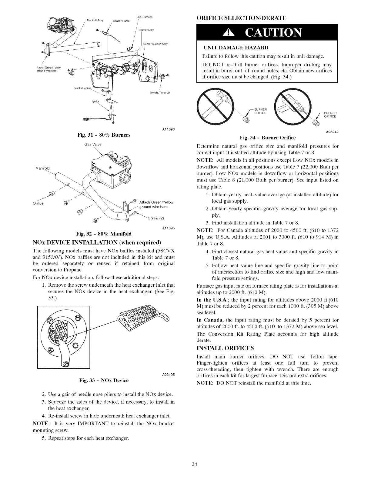
Bracket Ignito_
Fig. 31 -80% Burners
Gas Valve
\\
Manifold
Clp, Harness
Burner Assy
urner Support Assy
4_4P
Switch, Temp (2)
Al1390
Orifice (_/ .z¢p_ Attach Green/Yellow
J j ground wire here
@
Screw (2)
A11395
Fig. 32 -80% Manifold
NOx DEVICE INSTALLATION (when required)
The following models must have NOx baffles installed (58CVX
and 315JAV). NOx baffles are not included in this kit and must
be ordered separately or reused if retained from original
conversion to Propane.
For NOx device installation, follow these additional steps:
1. Remove the screw underneath the heat exchanger inlet that
secures the NOx device in the heat exchanger. (See Fig.
33.)
A02195
Fig. 33 -NOx Device
2. Use a pair of needle nose pliers to install the NOx device.
3. Squeeze the sides of the device, if necessary, to install in
the heat exchanger.
4. Re-install screw in hole underneath heat exchanger inlet.
NOTE: It is very IMPORTANT to reinstall the NOx bracket
mounting screw.
5. Repeat steps for each heat exchanger.
ORIFICE SELECTION/DERATE
UNIT DAMAGE HAZARD
Failure to follow this caution may result in unit damage.
DO NOT re-drill burner orifices. Improper drilling may
result in burrs, out-of-round holes, etc. Obtain new orifices
if orifice size must be changed. (Fig. 34.)
A96249
Fig. 34 - Burner Orifice
Determine natural gas orifice size and manifold pressures for
correct input at installed altitude by using Table 7 or 8.
NOTE: All models in all positions except Low NOx models in
downflow and horizontal positions use Table 7 (22,000 Btuh per
burner). Low NOx models in downflow or horizontal positions
must use Table 8 (21,000 Btuh per burner). See input listed on
rating plate.
1. Obtain yearly heat-value average (at installed altitude) for
local gas supply.
2. Obtain yearly specific-gravity average for local gas sup-
ply.
3. Find installation altitude in Table 7 or 8.
NOTE: For Canada altitudes of 2000 to 4500 ft. (610 to 1372
M), use U.S.A. Altitudes of 2001 to 3000 ft. (610 to 914 M) in
Table 7 or 8.
4. Find closest natural gas heat value and specific gravity in
Table 7 or 8.
5. Follow heat-value line and specific-gravity line to point
of intersection to find orifice size and high and low mani-
fold pressure settings.
Furnace gas input rate on furnace rating plate is for installations at
altitudes up to 2000 ft. (610 M).
In the U.S.A.; the input rating for altitudes above 2000 ft.(610
M) must be reduced by 2 percent for each 1000 ft. (305 M) above
sea level.
In Canada, the input rating must be derated by 5 percent for
altitudes of 2000 ft. to 4500 ft. (610 to 1372 M) above sea level.
The Conversion Kit Rating Plate accounts for high altitude
derate.
INSTALL ORIFICES
Install main burner orifices. DO NOT use Teflon tape.
Finger-tighten orifices at least one full turn to prevent
cross-threading, then tighten with wrench. There are enough
orifices in each kit for largest furnace. Discard extra orifices.
NOTE: DO NOT reinstall the manifold at this time.
24
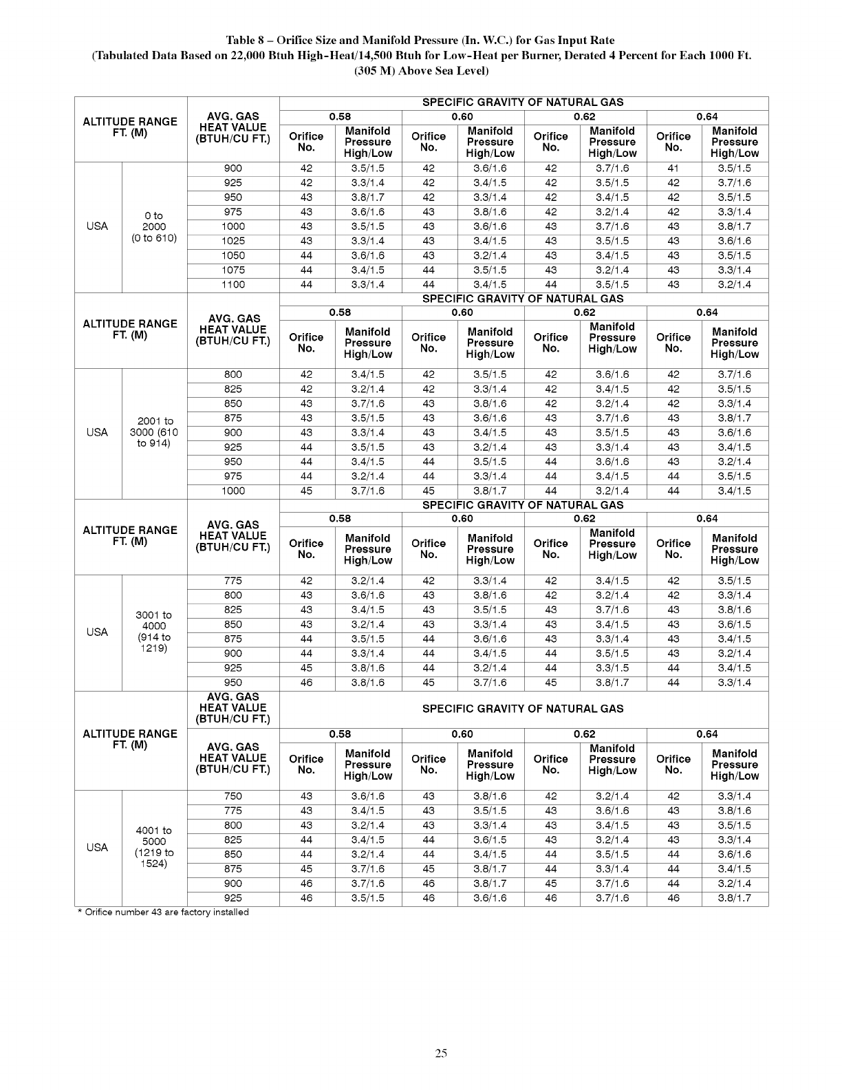
Table8- Orifice Size and Manifold Pressure (In. W.C.) for Gas Input Rate
(Tabulated Data Based on 22,000 Btuh High-Heat/14,500 Btuh for Low-Heat per Burner, Derated 4 Percent for Each 1000 Ft.
(305 M) Above Sea Level)
ALTITUDE RANGE
FT. (M)
0 to
USA 2000
(0 to 610)
ALTITUDE RANGE
FT. (M)
2001 to
USA 3000 (610
to 914)
ALTITUDE RANGE
FT. (a)
3001 to
4000
USA (914 to
1219)
ALTITUDE RANGE
FT. (M)
4001 to
5000
USA (1219 to
1524)
AVG. GAS
HEAT VALUE
(BTUH/CU FT.)
900
925
950
975
1000
1025
1050
1075
1100
AVG. GAS
HEAT VALUE
(BTUH/CU FT.)
800
825
850
875
900
925
950
975
1000
AVG. GAS
HEAT VALUE
(BTUH/CU FT.)
775
800
825
850
875
900
925
950
AVG, GAS
HEAT VALUE
(BTUH/CU FT.)
AVG. GAS
HEAT VALUE
(BTUH/CU FT.)
750
775
800
825
850
875
900
925
Orifice number 43 are factory installed
SPECIFIC GRAVITY OF NATURAL GAS
0.58 0.60
Orifice Manifold Orifice Manifold
No. Pressure No. Pressure
High/Low High/Low
42 3.5/1.5 42 3.6/1.6
42 3.3/1.4 42 3.4/1.5
43 3.8/1.7 42 3.3/1.4
43 3.6/1.6 43 3.8/1.6
43 3.5/1.5 43 3.6/1.6
43 3.3/1.4 43 3.4/1.5
44 3.6/1.6 43 3.2/1.4
44 3.4/1.5 44 3.5/1.5
44 3.3/1.4 44 3.4/1.5
0.58
Orifice Manifold
No. Pressure
High/Low
42 3.4/1.5
42 3.2/1.4
43 3.7/1.6
43 3.5/1.5
43 3.3/1.4
44 3.5/1.5
44 3.4/1.5
44 3.2/1.4
45 3.7/1.6
0.58
Orifice Manifold
No. Pressure
High/Low
42 3.2/1.4
43 3.6/1.6
43 3.4/1.5
43 3.2/1.4
44 3.5/1.5
44 3.3/1.4
45 3.8/1.6
46 3.8/1.6
0.62 0.64
Orifice Manifold Orifice Manifold
No. Pressure No. Pressure
High/Low High/Low
42 3.7/1.6 41 3.5/1.5
42 3.5/1.5 42 3.7/1.6
42 3.4/1.5 42 3.5/1.5
42 3.2/1.4 42 3.3/1.4
43 3.7/1.6 43 3.8/1.7
43 3.5/1.5 43 3.6/1.6
43 3.4/1.5 43 3.5/1.5
43 3.2/1.4 43 3.3/1.4
44 3.5/1.5 43 3.2/1.4
SPECIFIC GRAVITY OF NATURAL GAS
0.60 0.62
Manifold
Orifice Manifold Orifice Pressure Orifice
Pressure
No. High/Low No. High/Low No.
42 3.5/1.5 42 3.6/1.6 42
42 3.3/1.4 42 3.4/1.5 42
43 3.8/1.6 42 3.2/1.4 42
43 3.6/1.6 43 3.7/1.6 43
43 3.4/1.5 43 3.5/1.5 43
43 3.2/1.4 43 3.3/1.4 43
44 3.5/1.5 44 3.6/1.6 43
44 3.3/1.4 44 3.4/1.5 44
45 3.8/1.7 44 3.2/1.4 44
SPECIFIC GRAVITY OF NATURAL GAS
0.60 0.62
Manifold
Orifice Manifold Orifice Pressure
Pressure
No. High/Low No. High/Low
42 3.3/1.4 42 3.4/1.5
43 3.8/1.6 42 3.2/1.4
43 3.5/1.5 43 3.7/1.6
43 3.3/1.4 43 3.4/1.5
44 3.6/1.6 43 3.3/1.4
44 3.4/1.5 44 3.5/1.5
44 3.2/1.4 44 3.3/1.5
45 3.7/1.6 45 3.8/1.7
SPECIFIC GRAVITY OF NATURAL GAS
Orifice
No.
42
42
43
43
43
43
44
44
0.64
Manifold
Pressure
High/Low
3.7/1.6
3.5/1.5
3.3/1.4
3.8/1.7
3.6/1.6
3.4/1.5
3.2/1.4
3.5/1.5
3.4/1.5
0.64
Manifold
Pressure
High/Low
3.5/1.5
3.3/1.4
3.8/1.6
3.6/1.5
3.4/1.5
3.2/1.4
3.4/1.5
3.3/1.4
0.58 0.60 0.62 0.64
Manifold Manifold
Orifice Manifold Orifice Manifold Orifice Pressure Orifice
Pressure Pressure Pressure
No. High/Low No. High/Low No. High/Low No. High/Low
43 3.6/1.6 43 3.8/1.6 42 3.2/1.4 42 3.3/1.4
43 3.4/1.5 43 3.5/1.5 43 3.6/1.6 43 3.8/1.6
43 3.2/1.4 43 3.3/1.4 43 3.4/1.5 43 3.5/1.5
44 3.4/1.5 44 3.6/1.5 43 3.2/1.4 43 3.3/1.4
44 3.2/1.4 44 3.4/1.5 44 3.5/1.5 44 3.6/1.6
45 3.7/1.6 45 3.8/1.7 44 3.3/1.4 44 3.4/1.5
46 3.7/1.6 46 3.8/1.7 45 3.7/1.6 44 3.2/1.4
46 3.5/1.5 46 3.6/1.6 46 3.7/1.6 46 3.8/1.7
25
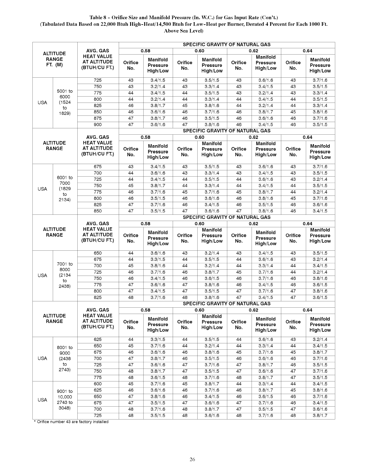
Table 8 -Orifice Size and Manifold Pressure (In. W.C.) for Gas Input Rate (Con't.)
(Tabulated Data Based on 22,000 Btuh High-Heat/14,500 Btuh for Low-Heat per Burner, Derated 4 Percent for Each 1000 Ft.
Above Sea Level)
ALTITUDE
RANGE
FT. (M)
5001 to
6000
USA (1524
to
1829)
ALTITUDE
RANGE
6001 to
7000
USA (1829
to
2134)
ALTITUDE
RANGE
7001 to
8000
USA (2134
to
2438)
ALTITUDE
RANGE
8001 to
9000
USA (2438
to
2743)
AVG. GAS
HEAT VALUE
AT ALTITUDE
(BTUH/CU FT.)
725
750
775
800
825
850
875
900
AVG. GAS
HEAT VALUE
AT ALTITUDE
(BTUH/CU FT.)
675
700
725
750
775
800
825
850
AVG. GAS
HEAT VALUE
AT ALTITUDE
(BTUH/CU FT.)
650
675
700
725
750
775
800
825
AVG, GAS
HEAT VALUE
AT ALTITUDE
(BTUH/CU FT.)
625
650
675
700
725
750
775
600
9001to 625
10,000 650
USA 2743to 675
3048) 700
725
Orifice number43arefactoryinstalled
0.58
Manifold Manifold
Orifice Orifice
Pressure Pressure
No. No.
High/Low High/Low
43 3.4/1.5 43 3.5/1.5
43 3.2/1.4 43 3.3/1.4
44 3.4/1.5 44 3.5/1.5
44 3.2/1.4 44 3.3/1.4
46 3.8/1.7 45 3.8/1.6
46 3.6/1.6 46 3.7/1.6
47 3.8/1.7 46 3.5/1.5
47 3.6/1.6 47 3.8/1.6
0.58
Manifold
Orifice Pressure
No. High/Low
43 3.4/1.5 43 3.5/1.5
44 3.6/1.6 43 3.3/1.4
44 3.4/1.5 44 3.5/1.5
45 3.8/1.7 44 3.3/1.4
46 3.7/1.6 45 3.7/1.6
46 3.5/1.5 46 3.6/1.6
47 3.7/1.6 46 3.4/1.5
47 3.5/1.5 47 3.6/1.6
SPECIFIC GRAVITY OF NATURAL GAS
0.60 0.62
SPECIFIC GRAVITY OF
0.60
Manifold
Orifice Pressure
No. High/Low
0.58
Manifold
Orifice Pressure
No. High/Low
44 3.6/1.6 43 3.2/1.4
44 3.3/1.5 44 3.5/1.5
45 3.8/1.6 44 3.2/1.4
46 3.7/1.6 46 3.8/1.7
46 3.4/1.5 46 3.6/1.5
47 3.6/1.6 47 3.8/1.6
47 3.4/1.5 47 3.5/1.5
48 3.7/1.6 48 3.8/1.6
SPECIFIC GRAVITY OF
0.60
Manifold
Orifice Pressure
No. High/Low
0.58
Manifold
Orifice Pressure
No. High/Low
44 3.3/1.5 44 3.5/1.5
45 3.7/1.6 44 3.2/1.4
46 3.6/1.6 46 3.8/1.6
47 3.8/1.7 46 3.5/1.5
47 3.6/1.6 47 3.7/1.6
48 3.8/1.7 47 3.5/1.5
48 3.6/1.5 48 3.7/1.6
45 3.7/1.6 45 3.8/1.7
46 3.6/1.6 46 3.7/1.6
47 3.8/1.6 46 3.4/1.5
47 3.5/1.5 47 3.6/1.6
48 3.7/1.6 48 3.8/1.7
48 3.5/1.5 48 3.6/1.6
SPECIFIC GRAVITY OF
0.60
Manifold
Orifice Pressure
No. High/Low
Manifold
Orifice Pressure
No. High/Low
43 3.6/1.6
43 3.4/1.5
43 3.2/1.4
44 3.4/1.5
44 3.2/1.4
45 3.8/1.7
45 3.5/1.5
45 3.4/1.5
NATURAL GAS
0.62
Manifold
Orifice Pressure
No. High/Low
43 3.6/1.6
43 3.4/1.5
44 3.6/1.6
44 3.4/1.5
45 3.8/1.7
46 3.8/1.6
46 3.5/1.5
47 3.8/1.6
NATURAL GAS
0,62
Manifold
Orifice Pressure
No. High/Low
43 3.4/1.5
44 3.6/1.6
44 3.3/1.4
45 3.7/1.6
46 3.7/1.6
46 3.4/1.5
47 3.7/1.6
47 3.4/1.5
NATURAL GAS
0,62
Manifold
Orifice Pressure
No. High/Low
44 3.6/1.6
44 3.3/1.4
45 3.7/1.6
46 3.6/1.6
47 3.8/1.7
47 3.6/1.6
48 3.8/1.7
44 3.3/1.4
46 3.8/1.7
46 3.6/1.5
47 3.7/1.6
47 3.5/1.5
48 3.7/1.6
Orifice
No.
43
43
43
44
44
45
46
46
Orifice
No.
43
43
43
44
44
45
46
46
Orifice
No.
43
43
44
44
46
46
47
47
Orifice
No.
43
44
45
46
46
47
47
44
45
46
46
47
48
0.64
Manifold
Pressure
High/Low
3.7/1.6
3.5/1.5
3.3/1.4
3.5/1.5
3.3/1.4
3.8/1.6
3.7/1.6
3.5/1.5
0.64
Manifold
Pressure
High/Low
3.7/1.6
3.5/1.5
3.2/1.4
3.5/1.5
3.2/1.4
3.7/1.6
3.6/1.6
3.4/1.5
0.64
Manifold
Pressure
High/Low
3.5/1.5
3.2/1.4
3.4/1.5
3.2/1.4
3.8/1.6
3.6/1.5
3.8/1.6
3.6/1.5
0.64
Manifold
Pressure
High/Low
3.2/1.4
3.4/1.5
3.8/1.7
3.7/1.6
3.5/1.5
3.7/1.6
3.5/1.5
3.4/1.5
3.8/1.6
3.7/1.6
3.4/1.5
3.6/1.6
3.8/1.7
2d
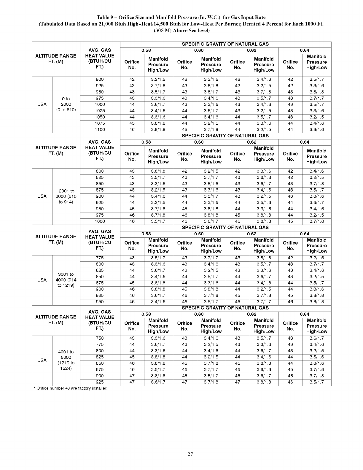
Table 9 - Orifice Size and Manifold Pressure (In. W.C.) for Gas Input Rate
(Tabulated Data Based on 21,000 Btuh High-Heat/14,500 Btuh for Low-Heat Per Burner, Derated 4 Percent for Each 1000 Ft.
(305 M) Above Sea level)
ALTITUDE RANGE
FT. (M)
0 to
USA 2000
(0 to 610)
ALTITUDE RANGE
FT. (M)
2001 to
USA 3000 (610
to 914)
ALTITUDE RANGE
FT. (M)
3001 to
USA 4000 (914
to 1219)
ALTITUDE RANGE
FT. (M)
4001 to
5000
USA (1219 to
1524)
AVG, GAS
HEAT VALUE
(BTUH/CU
FT.)
900
925
950
975
1000
1025
1050
1075
1100
AVG, GAS
HEAT VALUE
(BTUH/CU
FT.)
800
825
850
875
900
925
950
975
1000
AVG. GAS
HEAT VALUE
(BTUH/CU
FT.)
775
800
825
850
875
900
925
950
AVG, GAS
HEAT VALUE
(BTUH/CU
FT.)
750
775
800
825
850
875
900
925
Orifice number 43 are factory installed
SPECIFIC GRAVITY OF NATURAL GAS
0.58 0.60 0.62 0.64
Manifold
Manifold Manifold Manifold
Orifice Orifice Orifice Orifice Pressure
Pressure Pressure Pressure
No. High/Low No. High/Low No. High/Low No. High/Low
42 3.2/1.5 42 3.3/1.6 42 3.4/1.6 42 3.5/1.7
43 3.7/1.8 43 3.8/1.8 42 3.2/1.5 42 3.3/1.6
43 3.5/1.7 43 3.6/1.7 43 3.7/1.8 43 3.8/1.8
43 3.3/1.6 43 3.4/1.6 43 3.5/1.7 43 3.7/1.7
44 3.6/1.7 43 3.3/1.6 43 3.4/1.6 43 3.5/1.7
44 3.4/1.6 44 3.6/1.7 43 3.2/1.5 43 3.3/1.6
44 3.3/1.6 44 3.4/1.6 44 3.5/1.7 43 3.2/1.5
45 3.8/1.8 44 3.2/1.5 44 3.3/1.6 44 3.4/1.6
46 3.8/1.8 45 3.7/1.8 44 3.2/1.5 44 3.3/1.6
SPECIFIC GRAVITY OF NATURAL GAS
0,58 0,60 0,62 0,64
Manifold
Manifold Manifold Manifold
Orifice Orifice Orifice Pressure Orifice
Pressure Pressure Pressure
No. High/Low No. High/Low No. High/Low No. High/Low
43 3.8/1.8 42 3.2/1.5 42 3.3/1.6 42 3.4/1.6
43 3.5/1.7 43 3.7/1.7 43 3.8/1.8 42 3.2/1.5
43 3.3/1.6 43 3.5/1.6 43 3.6/1.7 43 3.7/1.8
43 3.2/1.5 43 3.3/1.6 43 3.4/1.6 43 3.5/1.7
44 3.4/1.6 44 3.5/1.7 43 3.2/1.5 43 3.3/1.6
44 3.2/1.5 44 3.3/1.6 44 3.5/1.6 44 3.6/1.7
45 3.7/1.8 45 3.8/1.8 44 3.3/1.6 44 3.4/1.6
46 3.7/1.8 46 3.8/1.8 45 3.8/1.8 44 3.2/1.5
46 3.5/1.7 46 3.6/1.7 46 3.8/1.8 45 3.7/1.8
SPECIFIC GRAVITY OF NATURAL GAS
0.58 0.60 0.62 0.64
Manifold Manifold Manifold Manifold
Orifice Orifice Orifice Orifice
Pressure Pressure Pressure Pressure
No. No. No. No.
High/Low High/Low High/Low High/Low
43 3.5/1.7 43 3.7/1.7 43 3.8/1.8 42 3.2/1.5
43 3.3/1.6 43 3.4/1.6 43 3.5/1.7 43 3.7/1.7
44 3.6/1.7 43 3.2/1.5 43 3.3/1.6 43 3.4/1.6
44 3.4/1.6 44 3.5/1.7 44 3.6/1.7 43 3.2/1.5
45 3.8/1.8 44 3.3/1.6 44 3.4/1.6 44 3.5/1.7
46 3.8/1.8 45 3.8/1.8 44 3.2/1.5 44 3.3/1.6
46 3.6/1.7 46 3.7/1.8 45 3.7/1.8 45 3.8/1.8
46 3.4/1.6 46 3.5/1.7 46 3.7/1.7 46 3.8/1.8
SPECIFIC GRAVITY OF NATURAL GAS
0,58 0,60 0,62 0,64
Manifold Manifold Manifold Manifold
Orifice Orifice Orifice Orifice
Pressure Pressure Pressure Pressure
No. No. No. No.
High/Low High/Low High/Low High/Low
43 3.3/1.6 43 3.4/1.6 43 3.5/1.7 43 3.6/1.7
44 3.6/1.7 43 3.2/1.5 43 3.3/1.6 43 3.4/1.6
44 3.3/1.6 44 3.4/1.6 44 3.6/1.7 43 3.2/1.5
45 3.8/1.8 44 3.2/1.5 44 3.4/1.6 44 3.5/1.6
46 3.8/1.8 45 3.7/1.8 45 3.8/1.8 44 3.3/1.6
46 3.5/1.7 46 3.7/1.7 46 3.8/1.8 45 3.7/1.8
47 3.8/1.8 46 3.5/1.7 46 3.6/1.7 46 3.7/1.8
47 3.6/1.7 47 3.7/1.8 47 3.8/1.8 46 3.5/1.7
27
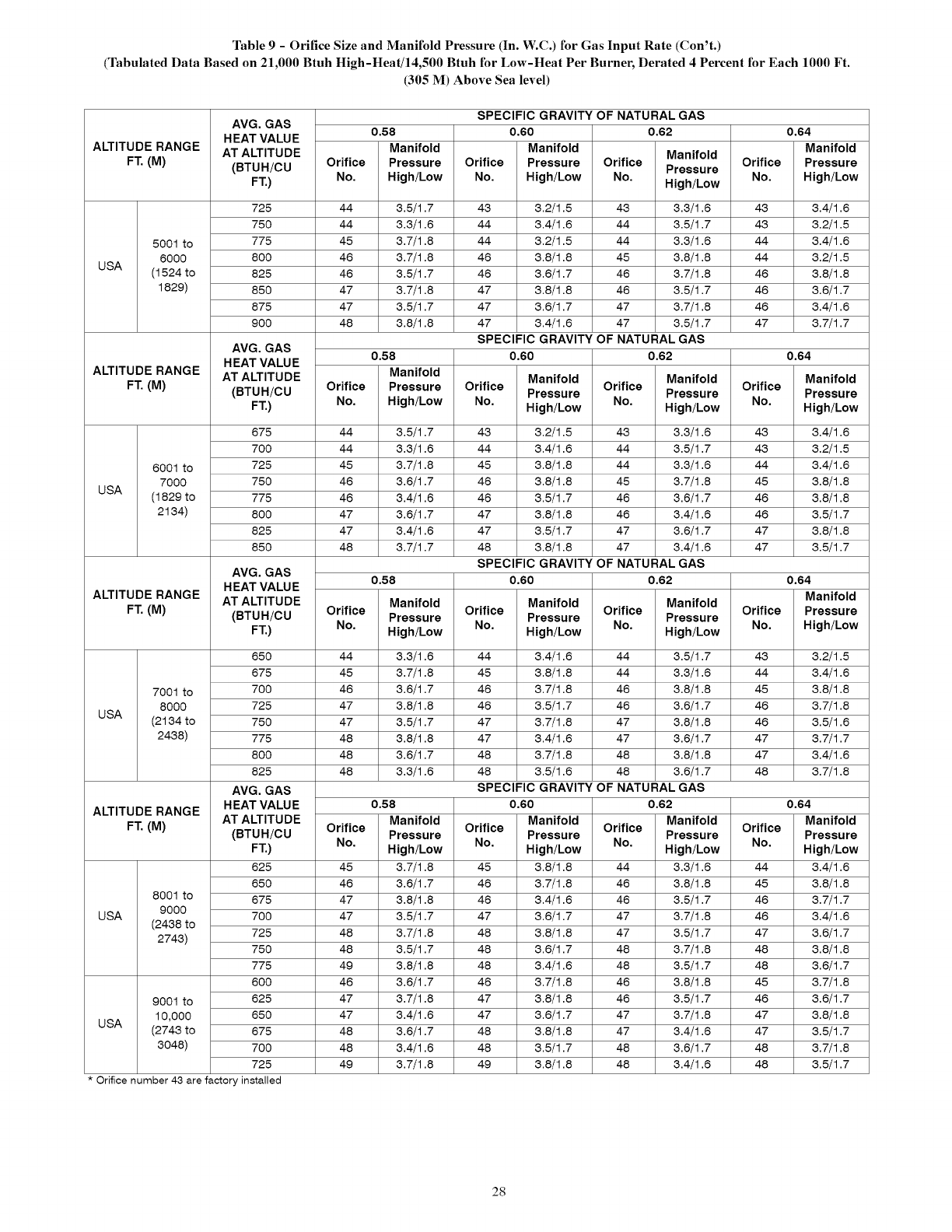
Table 9 - Orifice Size and Manifold Pressure (In. W.C.) for Gas Input Rate (Con't.)
(Tabulated Data Based on 21,000 Btuh High-Heat/14,500 Btuh for Low-Heat Per Burner, Derated 4 Percent for Each 1000 Ft.
(305 M) Above Sea level)
ALTITUDE RANGE
FT. (M)
5001 to
6000
USA (1524 to
1829)
ALTITUDE RANGE
FT. (M)
6001 to
7000
USA (1829 to
2134)
ALTITUDE RANGE
FT. (M)
AVG. GAS
HEAT VALUE
AT ALTITUDE
(BTUH/CU
FT.)
725
750
775
800
825
850
875
900
AVG. GAS
HEAT VALUE
AT ALTITUDE
(BTUH/CU
FT.)
675
700
725
750
775
800
825
850
AVG. GAS
HEAT VALUE
AT ALTITUDE
(BTUH/CU
FT.)
650
675
7001 to 700
8000 725
USA (2164 to 750
2468) 775
800
825
AVG, GAS
HEAT VALUE
ALTITUDE RANGE AT ALTITUDE
FT. (M) (BTUH/CU
FT.)
625
650
8001 to 675
USA 9000 700
(2468 to
2746) 725
750
775
600
9001 to 625
10,000 650
USA (2746 to 675
3048) 700
725
Orifice number 43 are factory installed
SPECIFIC GRAVITY OF NATURAL GAS
0.58 0.60
Manifold Manifold
Orifice Pressure Orifice Pressure
No. High/Low No. High/Low
44 3.5/1.7 46 3.2/1.5
44 3.6/1.6 44 3.4/1.6
45 3.7/1.8 44 3.2/1.5
46 3.7/1.8 46 3.8/1.8
46 3.5/1.7 46 3.6/1.7
47 3.7/1.8 47 3.8/1.8
47 3.5/1.7 47 3.6/1.7
48 3.8/1.8 47 3.4/1.6
SPECIFIC GRAVITY OF
0.58 0.60
Manifold Manifold
Orifice Pressure Orifice Pressure
No. High/Low No. High/Low
44 3.5/1.7 43 3.2/1.5
44 3.3/1.6 44 3.4/1.6
45 6.7/1.8 45 6.8/1.8
46 3.6/1.7 46 3.8/1.8
46 3.4/1.6 46 3.5/1.7
47 3.6/1.7 47 3.8/1.8
47 3.4/1.6 47 3.5/1.7
48 3.7/1.7 48 3.8/1.8
SPECIFIC GRAVITY OF
0.58 0.60
Manifold Manifold
Orifice Orifice
Pressure Pressure
No. No.
High/Low High/Low
44 3.3/1.6 44 3.4/1.6
45 6.7/1.8 45 6.8/1.8
46 3.6/1.7 46 3.7/1.8
47 3.8/1.8 46 3.5/1.7
47 6.5/1.7 47 6.7/1.8
48 3.8/1.8 47 3.4/1.6
48 3.6/1.7 48 3.7/1.8
48 3.3/1.6 48 3.5/1.6
SPECIFIC GRAVITY OF
0.58 0.60
Manifold Manifold
Orifice Orifice
Pressure Pressure
No. No.
High/Low High/Low
45 6.7/1.8 45 6.8/1.8
46 3.6/1.7 46 3.7/1.8
47 3.8/1.8 46 3.4/1.6
47 3.5/1.7 47 3.6/1.7
48 3.7/1.8 48 3.8/1.8
48 3.5/1.7 48 3.6/1.7
49 3.8/1.8 48 3.4/1.6
46 3.6/1.7 46 3.7/1.8
47 3.7/1.8 47 3.8/1.8
47 3.4/1.6 47 3.6/1.7
48 3.6/1.7 48 3.8/1.8
48 3.4/1.6 48 3.5/1.7
49 3.7/1.8 49 3.8/1.8
0.62 0.64
Manifold
Manifold
Orifice Orifice Pressure
Pressure
No. High/Low No. High/Low
43 3.3/1.6 43 3.4/1.6
44 3.5/1.7 46 3.2/1.5
44 3.3/1.6 44 3.4/1.6
45 6.8/1.8 44 6.2/1.5
46 3.7/1.8 46 3.8/1.8
46 3.5/1.7 46 3.6/1.7
47 3.7/1.8 46 3.4/1.6
47 6.5/1.7 47 6.7/1.7
NATURAL GAS
0,62 0.64
Manifold Manifold
Orifice Orifice
Pressure Pressure
No. No.
High/Low High/Low
43 3.3/1.6 43 3.4/1.6
44 3.5/1.7 46 3.2/1.5
44 3.3/1.6 44 3.4/1.6
45 6.7/1.8 45 6.8/1.8
46 3.6/1.7 46 3.8/1.8
46 3.4/1.6 46 3.5/1.7
47 3.6/1.7 47 3.8/1.8
47 3.4/1.6 47 3.5/1.7
NATURAL GAS
0,62 0.64
Manifold
Manifold
Orifice Orifice Pressure
Pressure
No. High/Low No. High/Low
44 3.5/1.7 46 3.2/1.5
44 3.3/1.6 44 3.4/1.6
46 3.8/1.8 45 3.8/1.8
46 3.6/1.7 46 3.7/1.8
47 3.8/1.8 46 3.5/1.6
47 3.6/1.7 47 3.7/1.7
48 3.8/1.8 47 3.4/1.6
48 3.6/1.7 48 3.7/1.8
NATURAL GAS
0,62 0.64
Manifold Manifold
Orifice Orifice
Pressure Pressure
No. No.
High/Low High/Low
44 3.3/1.6 44 3.4/1.6
46 3.8/1.8 45 3.8/1.8
46 3.5/1.7 46 3.7/1.7
47 3.7/1.8 46 3.4/1.6
47 3.5/1.7 47 3.6/1.7
48 3.7/1.8 48 3.8/1.8
48 3.5/1.7 48 3.6/1.7
46 3.8/1.8 45 3.7/1.8
46 3.5/1.7 46 3.6/1.7
47 3.7/1.8 47 3.8/1.8
47 3.4/1.6 47 3.5/1.7
48 3.6/1.7 48 3.7/1.8
48 3.4/1.6 48 3.5/1.7
28
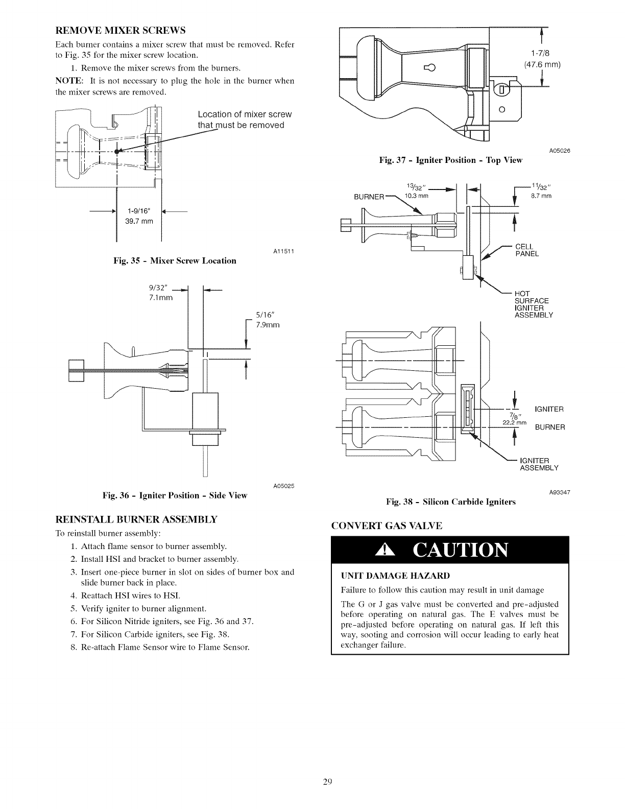
REMOVE MIXER SCREWS
Each burner contains a mixer screw that must be removed. Refer
to Fig. 35 for the mixer screw location.
1. Remove the mixer screws from the burners.
NOTE: It is not necessary to plug the hole in the burner when
the mixer screws are removed.
i
I
--_[ 1-9/16"
1
39.7 mm
Location of mixer screw
that must be removed
Fig. 35 - Mixer Screw Location
Al1511
Fig. 36 -Igniter Position - Side View
5/16"
7.9ram
A05025
REINSTALL BURNER ASSEMBLY
To reinstall burner assembly:
1. Attach flame sensor to burner assembly.
2. Install HSI and bracket to burner assembly.
3. Insert one-piece burner in slot on sides of burner box and
slide burner back in place.
4. Reattach HSI wires to HSI.
5. Verify igniter to burner alignment.
6. For Silicon Nitride igniters, see Fig. 36 and 37.
7. For Silicon Carbide igniters, see Fig. 38.
8. Re-attach Flame Sensor wire to Flame Sensor.
f
1-7/8
O (47'imm)
A05026
Fig. 37 -Igniter Position -Top View
/
_,_11/32 ,,
8.7 mm
f CELL
PANEL
_HOT
SURFACE
IGNITER
ASSEMBLY
{ IGNITER
7/8,,
22.2 mm
BURNER
IGNITER
ASSEMBLY
Fig. 38 -Silicon Carbide Igniters
CONVERT GAS VALVE
A93347
[]NIT DAMAGE HAZARD
Failure to follow this caution may result in unit damage
The G or J gas valve must be converted and pre-adjusted
before operating on natural gas. The E valves must be
pre-adjusted before operating on natural gas. If left this
way, sooting and corrosion will occur leading to early heat
exchanger failure.
29
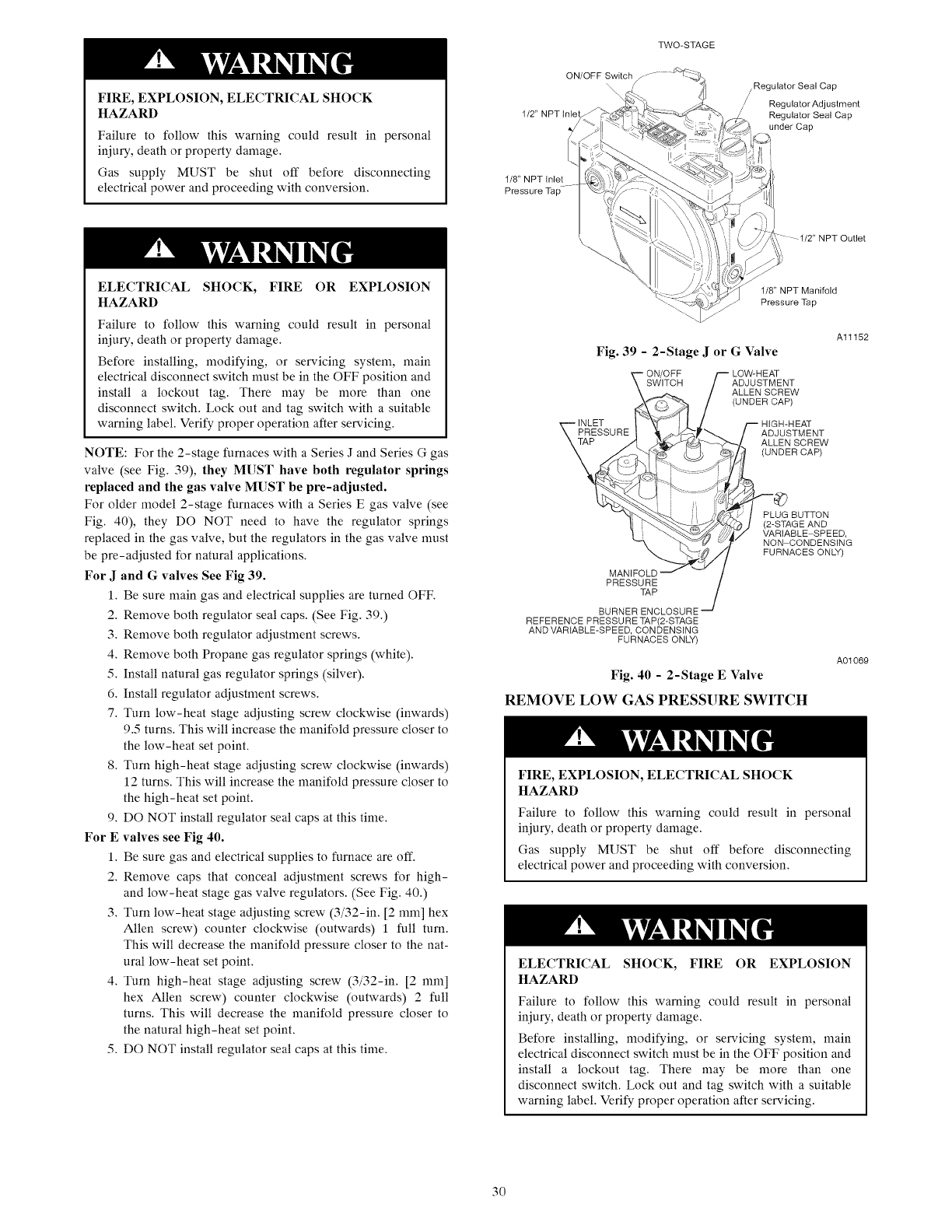
FIRE,EXPLOSION,ELECTRICALSHOCK
HAZARD
Failureto follow this warning could result in personal
iniury, death or property damage.
Gas supply MUST be shut off before disconnecting
electrical power and proceeding with conversion.
TWO-STAGE
ON/OFF Switch f ...... _:::_-_
,,
1/2' NPT inlet
1/8" NPT Inlet
Pressure Tap
,Regulator Seal Cap
Regulator Adjustment
Regulator Seal Cap
under Cap
ELECTRICAL SHOCK, FIRE OR EXPLOSION
HAZARD
Failure to follow this warning could result in personal
iniury, death or property damage.
Before installing, modifying, or servicing system, main
electrical disconnect switch must be in the OFF position and
install a lockout tag. There may be more than one
disconnect switch. Lock out and tag switch with a suitable
warning label. Verify proper operation after servicing.
NOTE: For the 2-stage furnaces with a Series J and Series G gas
valve (see Fig. 39), they MUST have both regulator springs
replaced and the gas valve MUST be pre-adjusted.
For older model 2-stage furnaces with aSeries E gas valve (see
Fig. 40), they DO NOT need to have the regulator springs
replaced in the gas valve, but the regulators in the gas valve must
be pre-adjusted for natural applications.
For J and G valves See Fig 39.
1. Be sure main gas and electrical supplies are turned OFF.
2. Remove both regulator seal caps. (See Fig. 39.)
3. Remove both regulator adjustment screws.
4. Remove both Propane gas regulator springs (white).
5. Install natural gas regulator springs (silver).
6. Install regulator adjustment screws.
7. Turn low-heat stage adjusting screw clockwise (inwards)
9.5 turns, This will increase the manifold pressure closer to
the low-heat set point.
8. Turn high-heat stage adjusting screw clockwise (inwards)
12 turns. This will increase the manifold pressure closer to
the high-heat set point.
9. DO NOT install regulator seal caps at this time,
For E valves see Fig 40.
1. Be sure gas and electrical supplies to furnace are off.
2. Remove caps that conceal adjustment screws for high-
and low-heat stage gas valve regulators. (See Fig. 40.)
3. Turn low-heat stage adjusting screw (3/32-in. [2 mm] hex
Allen screw) counter clockwise (outwards) 1 full turn.
This will decrease the manifold pressure closer to the nat-
ural low-heat set point.
4. Turn high-heat stage adjusting screw (3/32-in. [2 mm]
hex Allen screw) counter clockwise (outwards) 2 full
turns. This will decrease the manifold pressure closer to
the natural high-heat set point.
5. DO NOT install regulator seal caps at this time.
NPT Outlet
1/8" NPT Manifold
Pressure Tap
Al1152
Fig. 39 - 2-Stage J or G Valve
LOW-HEAT
ADJUSTMENT
ALLEN SCREW
(UNDER CAP)
-- HIGH-HEAT
ADJUSTMENT
ALLEN SCREW
(UNDER CAP)
PLUG BUTTON
(2-STAG E AND
t/ VARIABLE SPEED,
NON CONDENSING
FURNACES ONLY)
MANIFOLD
PRESSURE
TAP
BURNER ENCLOSURE "_/
REFERENCE PRESSURE TAP(2-STAGE
AND VARIABLE-SPEED, CONDENSING
FURNACES ONLY)
A01069
Fig. 40 - 2-Stage E Valve
REMOVE LOW GAS PRESSURE SWITCH
FIRE, EXPLOSION, ELECTRICAL SHOCK
HAZARD
Failure to follow this warning could result in personal
iniury, death or property damage.
Gas supply MUST be shut off before disconnecting
electrical power and proceeding with conversion.
ELECTRICAL SHOCK, FIRE OR EXPLOSION
HAZARD
Failure to follow this warning could result in personal
iniury, death or property damage.
Before installing, modifying, or servicing system, main
electrical disconnect switch must be in the OFF position and
install a lockout tag. There may be more than one
disconnect switch. Lock out and tag switch with a suitable
warning label. Verify proper operation after servicing.
30
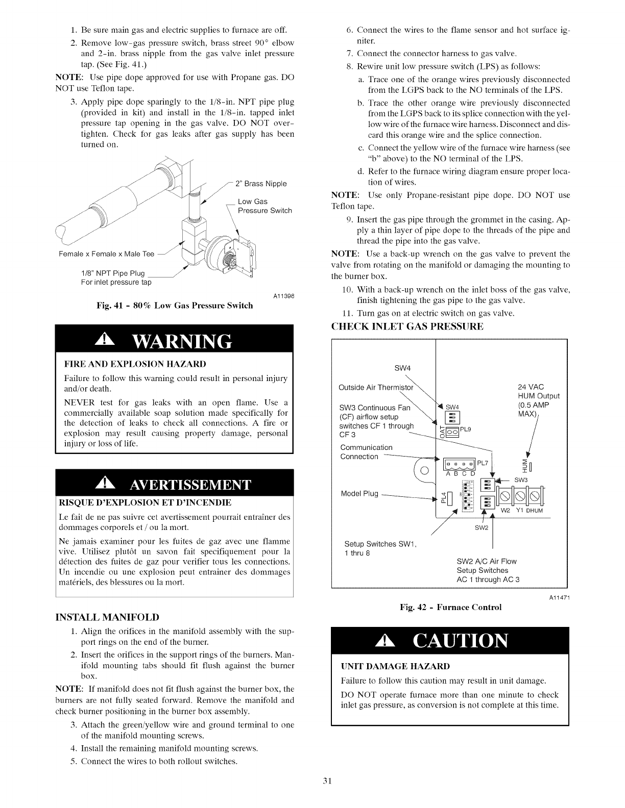
1.Besuremaingasandelectricsuppliesto furnace are off.
2. Remove low-gas pressure switch, brass street 90 ° elbow
and 2-in. brass nipple from the gas valve inlet pressure
tap. (See Fig. 41.)
NOTE: Use pipe dope approved for use with Propane gas. DO
NOT use Teflon tape.
3. Apply pipe dope sparingly to the l/8-in. NPT pipe plug
(provided in kit) and install in the l/8-in, tapped inlet
pressure tap opening in the gas valve. DO NOT over-
tighten. Check for gas leaks after gas supply has been
turned on.
2" Brass Nipple
Low Gas
Pressure Switch
Female x Female x Male Tee
1/8" NPT Pipe Plug /
For inlet pressure tap
Fig. 41 -80% Low Gas Pressure Switch
Al1398
FIRE AND EXPLOSION HAZARD
Failure to follow this warning could result in personal injury
and/or death.
NEVER test for gas leaks with an open flame. Use a
commercially available soap solution made specifically for
the detection of leaks to check all connections. A fire or
explosion may result causing property damage, personal
injury or loss of life,
RISQUE D'EXPLOSION ET D'INCENDIE
Le fair de ne pas suivre cet avertissement pourrait entra*ner des
dommages corporels et /ou la mort.
Ne jamais examiner pour les fuites de gaz avec une flamme
vive. Utilisez plut6t un savon fair specifiquement pour la
d6tection des fuites de gaz pour verifier tous les connections.
Un incendie ou une explosion peut entrainer des dommages
mat6riels, des blessures ou la mort.
INSTALL MANIFOLD
1. Align the orifices in the manifold assembly with the sup-
port rings on the end of the burner.
2. Insert the orifices in the support rings of the burners. Man-
ifold mounting tabs should fit flush against the burner
box.
NOTE: If manifold does not fit flush against the burner box, the
burners are not fully seated forward. Remove the manifold and
check burner positioning in the burner box assembly.
3. Attach the green/yellow wire and ground terminal to one
of the manifold mounting screws.
4. Install the remaining manifold mounting screws.
5. Connect the wires to both rollout switches.
6. Connect the wires to the flame sensor and hot surface ig-
niter.
7. Connect the connector harness to gas valve.
8. Rewire unit low pressure switch (LPS) as follows:
a. Trace one of the orange wires previously disconnected
from the LGPS back to the NO terminals of the LPS.
b. Trace the other orange wire previously disconnected
from the LGPS back to its splice connection with the yel-
low wire of the furnace wire harness. Disconnect and dis-
card this orange wire and the splice connection.
c. Connect the yellow wire of the furnace wire harness (see
"b" above) to the NO terminal of the LPS.
d. Refer to the furnace wiring diagram ensure proper loca-
tion of wires.
NOTE: Use only Propane-resistant pipe dope. DO NOT use
Teflon tape.
9. Insert the gas pipe through the grommet in the casing. Ap-
ply a thin layer of pipe dope to the threads of the pipe and
thread the pipe into the gas valve.
NOTE: Use a back-up wrench on the gas valve to prevent the
valve from rotating on the manifold or damaging the mounting to
the burner box.
10. With a back-up wrench on the inlet boss of the gas valve,
finish tightening the gas pipe to the gas valve.
11. Turn gas on at electric switch on gas valve.
CHECK INLET GAS PRESSURE
SW4
Outside Air Thermi,'
SW3 Continuous
(CF) airflow setup
switches CF 1 through
CF 3 '-_
Communication
24 VAC
HUM Output
(O.5AMP
in
SW4
[]
<_I=_ PL9
O_
._ol [_ SW3
Mode, P,ug_ _-N _i_,:_ __
/,_ /_Zl _ W2 Yt DHUM
SW2
Setup Switches SWl,
1 thru 8
SW2 A/C Air Flow
Setup Switches
AC 1 through AC 3
Fig. 42 - Furnace Control
Al1471
UNIT DAMAGE HAZARD
Failure to follow this caution may result in unit damage.
DO NOT operate furnace more than one minute to check
inlet gas pressure, as conversion is not complete at this time.
31
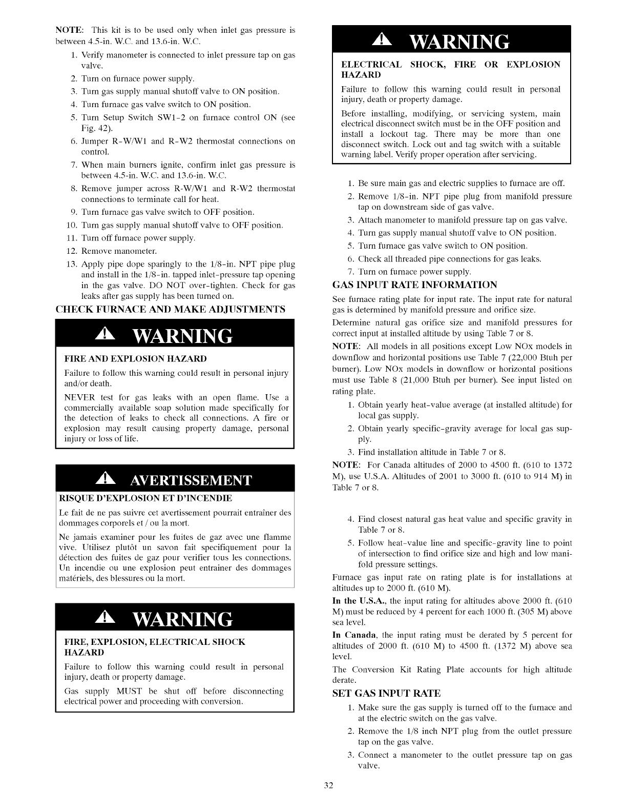
NOTE: This kit is to be used only when inlet gas pressure is
between 4.5-in. W.C. and 13.6-in. W.C.
1. Verify manometer is connected to inlet pressure tap on gas
valve.
2. Turn on furnace power supply.
3. Turn gas supply manual shutoff valve to ON position.
4. Turn furnace gas valve switch to ON position.
5. Turn Setup Switch SWl-2 on furnace control ON (see
Fig. 42).
6. Jumper R-W/W1 and R-W2 thermostat connections on
control.
7. When main burners ignite, confirm inlet gas pressure is
between 4.5-in. W.C. and 13.6-in. W.C.
8. Remove jumper across R-W/W1 and R-W2 thermostat
connections to terminate call for heat.
9. Turn furnace gas valve switch to OFF position.
10. Turn gas supply manual shutoff valve to OFF position.
11. Turn off furnace power supply.
12. Remove manometer.
13. Apply pipe dope sparingly to the 1/8-in. NPT pipe plug
and install in the 1/8-in. tapped inlet-pressure tap opening
in the gas valve. DO NOT over-tighten. Check for gas
leaks after gas supply has been turned on.
CHECK FURNACE AND MAKE ADJUSTMENTS
FIRE AND EXPLOSION HAZARD
Failure to follow this warning could result in personal injury
and/or death.
NEVER test for gas leaks with an open flame. Use a
commercially available soap solution made specifically for
the detection of leaks to check all connections. A fire or
explosion may result causing property damage, personal
injury or loss of life.
RISQUE D'EXPLOSION ET D'INCENDIE
Le fait de ne pas suivre cet avertissement pourrait entrai'nerdes
dommages corporels et /ou la mort.
Ne jamais examiner pour les fuites de gaz avec une flamme
vive. Utilisez plut6t un savon fait specifiquement pour la
d6tection des fuites de gaz pour verifier tousles connections.
Un incendie ou une explosion peut entrainer des dommages
mat6riels, des blessures ou la mort.
FIRE, EXPLOSION, ELECTRICAL SHOCK
HAZARD
Failure to follow this warning could result in personal
iniury, death or property damage.
Gas supply MUST be shut off before disconnecting
electrical power and proceeding with conversion.
ELECTRICAL SHOCK, FIRE OR EXPLOSION
HAZARD
Failure to follow this warning could result in personal
iniury, death or property damage.
Before installing, modifying, or servicing system, main
electrical disconnect switch must be in the OFF position and
install a lockout tag. There may be more than one
disconnect switch. Lock out and tag switch with a suitaMe
warning label. Verify proper operation after servicing.
1. Be sure main gas and electric supplies to furnace are off.
2. Remove 1/8-in. NPT pipe plug from manifold pressure
tap on downstream side of gas valve,
3. Attach manometer to manifold pressure tap on gas valve,
4. Turn gas supply manual shutoff valve to ON position,
5. Turn furnace gas valve switch to ON position,
6. Check all threaded pipe connections for gas leaks,
7. Turn on furnace power supply,
GAS INPUT RATE INFORMATION
See furnace rating plate for input rate. The input rate for natural
gas is determined by manifold pressure and orifice size.
Determine natural gas orifice size and manifold pressures for
correct input at installed altitude by using Table 7 or 8.
NOTE: All models in all positions except Low NOx models in
downflow and horizontal positions use Table 7 (22,000 Btuh per
burner). Low NOx models in downflow or horizontal positions
must use Table 8 (21,000 Btuh per burner). See input listed on
rating plate.
1. Obtain yearly heat-value average (at installed altitude) for
local gas supply.
2. Obtain yearly specific-gravity average for local gas sup-
ply.
3. Find installation altitude in Table 7 or 8.
NOTE: For Canada altitudes of 2000 to 4500 ft. (610 to 1372
M), use U.S.A. Altitudes of 2001 to 3000 ft. (610 to 914 M) in
Table 7 or 8.
4. Find closest natural gas heat value and specific gravity in
TaMe 7 or 8.
5. Follow heat-value line and specific-gravity line to point
of intersection to find orifice size and high and low mani-
fold pressure settings.
Furnace gas input rate on rating plate is for installations at
altitudes up to 2000 ft. (610 M).
In the U.S.A., the input rating for altitudes above 2000 ft. (610
M) must be reduced by 4 percent for each 1000 ft. (305 M) above
sea level.
In Canada, the input rating must be derated by 5percent for
altitudes of 2000 ft. (610 M) to 4500 ft. (1372 M) above sea
level.
The Conversion Kit Rating Plate accounts for high altitude
derate.
SET GAS INPUT RATE
1. Make sure the gas supply is turned off to the furnace and
at the electric switch on the gas valve.
2. Remove the 1/8 inch NPT plug from the outlet pressure
tap on the gas valve.
3. Connect a manometer to the outlet pressure tap on gas
valve.
32
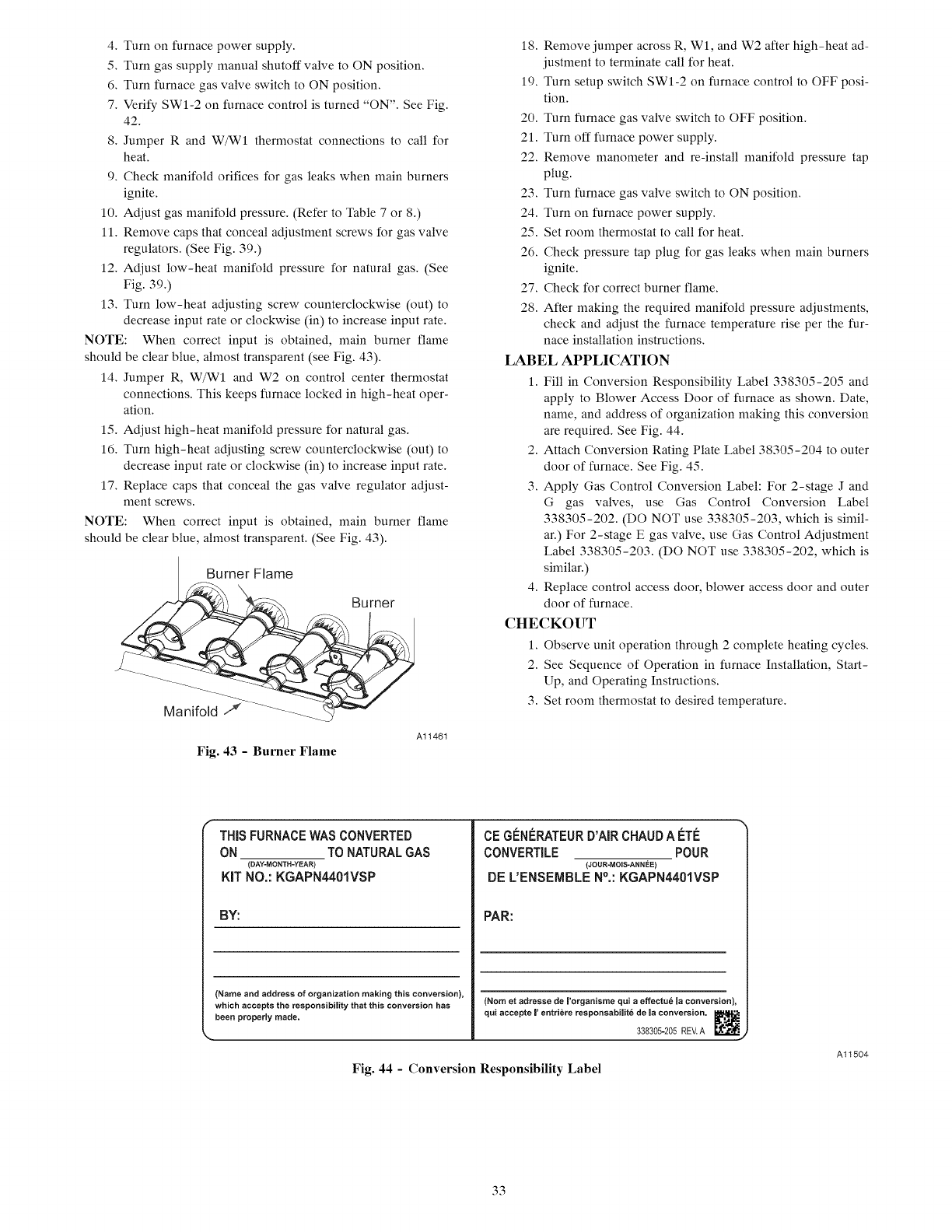
4.Turnonfurnacepowersupply.
5.TurngassupplymanualshutoffvalvetoONposition.
6.TurnfurnacegasvalveswitchtoONposition.
7.VerifySWI-2onfurnacecontrolisturned"ON".SeeFig.
42.
8.JumperRandW/WIthermostatconnectionstocallfor
heat.
9.Checkmanifoldorificesforgasleakswhenmainburners
ignite.
10.Adjustgasmanifoldpressure.(RefertoTable7or8.)
11.Removecapsthatconcealadjustmentscrewsforgasvalve
regulators.(SeeFig.39.)
12.Adjustlow-heatmanifoldpressurefornaturalgas.(See
Fig.39.)
13.Turnlow-heatadjustingscrewcounterclockwise(out)to
decreaseinputrateorclockwise(in)toincreaseinputrate.
NOTE:Whencorrectinputis obtained,mainburnerflame
shouldbeclearblue,almosttransparent(seeFig.43).
14.JumperR,W/WIandW2oncontrolcenterthermostat
connections.Thiskeepsfurnacelockedinhigh-heatoper-
ation.
15.Adjusthigh-heatmanifoldpressurefornaturalgas.
16.Turnhigh-heatadjustingscrewcounterclockwise(out)to
decreaseinputrateorclockwise(in)toincreaseinputrate.
17.Replacecapsthatconcealthegasvalveregulatoradjust-
mentscrews.
NOTE:Whencorrectinputis obtained,mainburnerflame
shouldbeclearblue,almosttransparent.(SeeFig.43).
Burner Flame
Burner
Fig. 43 -Burner Flame
Al1461
18. Remove jumper across R, Wl, and W2 after high-heat ad-
justment to terminate call for heat.
19. Turn setup switch SWI-2 on furnace control to OFF posi-
tion.
20. Turn furnace gas valve switch to OFF position.
21. Turn off furnace power supply.
22. Remove manometer and re-install manifold pressure tap
plug.
23. Turn furnace gas valve switch to ON position.
24. Turn on furnace power supply.
25. Set room thermostat to call for heat.
26. Check pressure tap plug for gas leaks when main burners
ignite.
27. Check for correct burner flame.
28. After making the required manifold pressure adjustments,
check and adjust the furnace temperature rise per the fur-
nace installation instructions.
LABEL APPLICATION
1. Fill in Conversion Responsibility Label 338305-205 and
apply to Blower Access Door of furnace as shown. Date,
name, and address of organization making this conversion
are required. See Fig. 44.
2. Attach Conversion Rating Plate Label 38305-204 to outer
door of furnace. See Fig. 45.
3. Apply Gas Control Conversion Label: For 2-stage J and
G gas valves, use Gas Control Conversion Label
338305-202. (DO NOT use 338305-203, which is simil-
ar.) For 2-stage E gas valve, use Gas Control Adjustment
Label 338305-203. (DO NOT use 338305-202, which is
similar.)
4. Replace control access door, blower access door and outer
door of furnace.
CHECKOUT
1. Observe unit operation through 2complete heating cycles.
2. See Sequence of Operation in fltrnace Installation, Start-
Up, and Operating Instructions.
3. Set room thermostat to desired temperature.
THIS FURNACE WAS CONVERTED
ON TO NATURAL GAS
(DAY-MONTH-YEAR)
KIT NO.: KGAPN4401VSP
BY:
(Name and address of organization making this conversion),
which accepts the responsibility that this conversion has
been properly made.
CE GI_NI_RATEUR D'AIR CHAUD A #TI_
CONVERTILE POUR
(JOUR-MOIS-ANNI_E)
DE L'ENSEIBLE N°.:KGAPN440IVSP
PAR:
(Nora et adresse de ['organisme qui a effectu6 la conversion),
qui accepte |' entri6re responsabilit6 de [a conversion,
338305-205 REV.A
Fig. 44 - Conversion Responsibility Label
Al1504
33
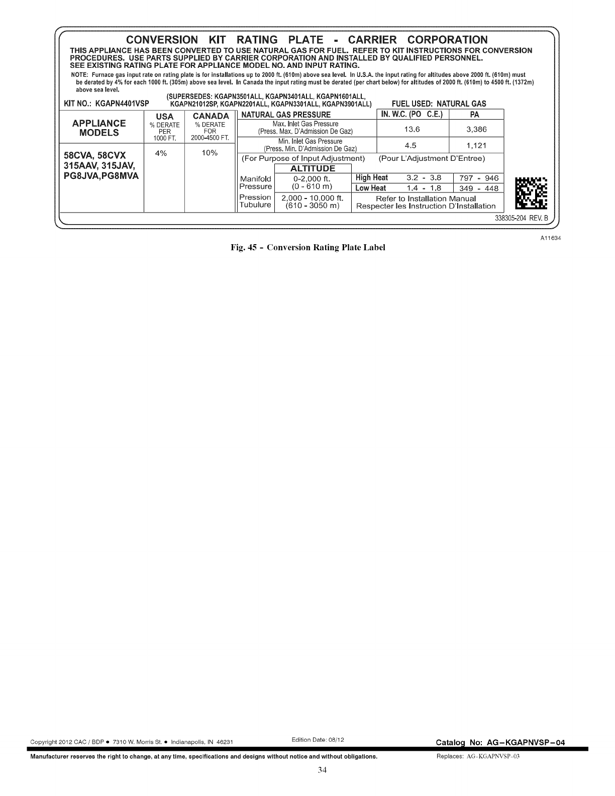
CONVERSION KiT RATING PLATE CARRIER CORPORATION
THiS APPLIANCE HAS BEEN CONVERTED TO USE NATURAL GAS FOR FUEL. REFER TO KiT iNSTRUCTiONS FOR CONVERSION
PROCEDURES. USE PARTS SUPPLIED BY CARRIER CORPORATION AND iNSTALLED BY QUALiFiED PERSONNEL.
SEE EXiSTiNG RATING PLATE FOR APPLIANCE MODEL NO. AND iNPUT RATING.
NOTE: Furnace gas inputrate on ratingplate is for installationsupto 2000ft. (610m)above sea level, inU.S.A.the inputratingfor altitudesabove 2000ft. (610m) must
be derated by 4%for each 1000ft. (305m)above sea level, in Canadathe input ratingmustbe derated (per chartbelow) for altitudesof 2000ft. (610m)to 4500ft. (1372m)
above sea level.
(SUPERSEDES: KGAPN3501ALL, KGAPN3401ALL, KGAPN1601ALL,
KIT NO.: KGAPN4401VSP KGAPN21012SP, KGAPN2201ALL, KGAPN3301ALL, KGAPN3901ALL)
USA CANADA NATURAL GAS PRESSURE
APPLIANCE %DERATE %DERATE Max. Inlet Gas Pressure
MODELS PER FOR (Press. Max. D'Admission De Gaz)
1000 FT. 20004500 FT. Min. Inlet Gas Pressure
4% 10% (Press. Min. D'Admissi0n De Gaz)
(For Purpose of Input Adjustment)
ALTITUDE
FUEL USED: NATURAL GAS
IN. W.C. (PO C.E.) PA
13.6 3,386
4.5 1,121
(Pour L'Adjustment D'Entree)
58CVA, 58CVX
315AAV, 315JAV,
PG8JVA,PG8MVA Manifold 0-2,000 ft. High Heat 3.2 =3.8 /797 =946 1,1,1,1,_',
Pressure (0-610m) Low Heat 1.4 = 1.8 ] 349 = 448
Pression 2,000 = 10,000 ft. Refer to Installation Manual
Tubulure (610 = 3050 m) Respecter les instruction D'lnstallation
_. 338305-204 REV. B
Al1634
Fig. 45 - Conversion Rating Plate Label
Copyright 2012 CAC /BDP •7310 W. Morris St. • Indianapolis. IN 46231 Edition Date:08/12
Manufacturer reserve8 the rightto change, at anytime, specification8 and design8 without notice and without obligations.
34
Catalo_l No: AG-KGAPNVSP-O4
Replaces: AG KGAPNVSP 03
