Carrier 33Cs450 01 Users Manual Rev. 5
33CS450-01 88-506
33cs45001 1047e247-1463-4055-9cb3-271a98bceb57 Carrier Thermostat 33CS450-01 User Guide |
2015-01-24
: Carrier Carrier-33Cs450-01-Users-Manual-311040 carrier-33cs450-01-users-manual-311040 carrier pdf
Open the PDF directly: View PDF ![]() .
.
Page Count: 113 [warning: Documents this large are best viewed by clicking the View PDF Link!]
- Page 1
- Page 2
- Page 3
- Page 4
- Page 5
- Page 6
- Page 7
- Page 8
- Page 9
- Page 10
- Page 11
- Page 12
- Page 13
- Page 14
- Page 15
- Page 16
- Page 17
- Page 18
- Page 19
- Page 20
- Page 21
- Page 22
- Page 23
- Page 24
- Page 25
- Page 26
- Page 27
- Page 28
- Page 29
- Page 30
- Page 31
- Page 32
- Page 33
- Page 34
- Page 35
- Page 36
- Page 37
- Page 38
- Page 39
- Page 40
- Page 41
- Page 42
- Page 43
- Page 44
- Page 45
- Page 46
- Page 47
- Page 48
- Page 49
- Page 50
- Page 51
- Page 52
- Page 53
- Page 54
- Page 55
- Page 56
- Page 57
- Page 58
- Page 59
- Page 60
- Page 61
- Page 62
- Page 63
- Page 64
- Page 65
- Page 66
- Page 67
- Page 68
- Page 69
- Page 70
- Page 71
- Page 72
- Page 73
- Page 74
- Page 75
- Page 76
- Page 77
- Page 78
- Page 79
- Page 80
- Page 81
- Page 82
- Page 83
- Page 84
- Page 85
- Page 86
- Page 87
- Page 88
- Page 89
- Page 90
- Page 91
- Page 92
- Page 93
- Page 94
- Page 95
- Page 96
- Page 97
- Page 98
- Page 99
- Page 100
- Page 101
- Page 102
- Page 103
- Page 104
- Page 105
- Page 106
- Page 107
- Page 108
- Page 109
- Page 110
- Page 111
- Page 112
- Page 113
7-DAY
7-DAY
PROGRAMMABLE
PROGRAMMABLE
DIGITAL
DIGITAL
THERMOSTAT
THERMOSTAT
HEAT
COOL
&
HEAT
PUMP
Accepts EZ Programmer
Remote Averaging
Programmable Output
Light Activation Equipped
Accepts Optional Humidity Module:
Controls Humidification,
Dehumidification and Reheat
Accepts Optional IR Remote Control
3 Configurable Outputs
Control up to 3 Heat &
2 Cool Stages
Adjustable 2nd & 3rd Stage
Timers & Deadbands
Backlit Display & Button
Legends
Aux Heat Indicator
Dry Contact Equipped
Outdoor Sensor Ready with
High/Low Readouts for the Day
Set Point Limiting
Economizer Control
Preoccupancy Fan Purge
3 Configurable Outputs
Control up to 3 Heat &
2 Cool Stages
Carrier Corporation 04/06
Use with most Air Conditioning & Heating Systems including: 1 or 2 Stage
Electric Cooling & 3 Stage Gas Heating, Heat Pump, Electric or Hydronic Heat.
OWNER’S
MANUAL
OWNER’S
MANUAL
OPTIONAL
HUMIDITY MODULE
OPTIONAL
HUMIDITY MODULE
Accepts the
Accepts the
COMMERCIALCOMMERCIAL
THERMOSTATTHERMOSTAT
P/N P/N
33CS450-0133CS450-01
AUTO
I2:00
Su
Pm
HEAT
COOL
72
74
Page i
NOTE: Due to variations in environmental conditions, it is not
always possible to achieve the desired humidification or
dehumidification setpoint.
This device complies with Part 15 of the FCC Rules. Operation is
subject to the following two conditions: (1) this device may not cause
harmful interference, and (2) this device must accept any interference
received, including interference that may cause undesired operation.
Follow the Installation Instructions before proceeding.
Set the thermostat mode to “OFF” prior to changing
settings in setup or restoring Factory Defaults.
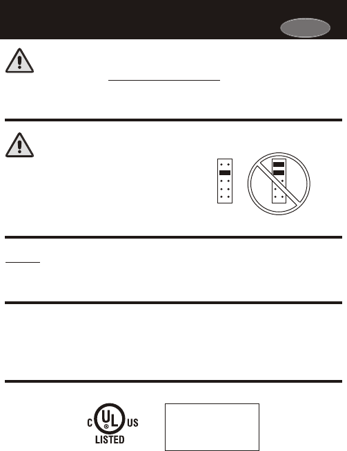
NEVER PUT MORE THAN ONE
JUMPER ON THE SAME MISC
JUMPER BLOCK!
THIS MAY DAMAGE YOUR
THERMOSTAT.
CAUTION
C
c
F
FOR HOME OR OFFICE USE
Tested to Comply
with FCC Standards
Thermostat 33CS450-01
4Z95
CAUTION
MISC3 MISC3
OK
Carrier
Page ii
Page 14.1
Section 14 Contents:
Adjusting the Heat/Cool
Differential..............................14.2
Adjusting the Cycles
Per Hour..................................14.3
Adjusting the Deadband..........14.4
Adjusting the Minutes of
Run-Time Before the
Next Stage...............................14.6
Selecting 2nd Stage Turn
Off Temperature.....................14.7
SECTION 14
Timers and DeadbandsTimers and Deadbands
14
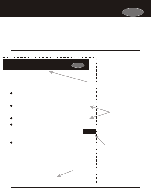
The first page of each section contains a more detailed list of the contents
within that section, such as the example page shown below.
The Table of Contents divides the thermostat features into sections
making it easier to quickly find information.
In addition, this manual also has an Index to help you find any information
regarding this thermostat quickly.
How to Use This ManualHow to Use This Manual
Header shows section #
and title of section
Section contents
Visible section tab
on the side of the
page
Section and page #
Carrier
Carrier

Glossary of TermsGlossary of Terms
Page iii
Auto-Changeover: A mode in which the thermostat will turn on
the heating or cooling based on room temperature demand.
Configurable Output Jumper: Using jumpers on the thermostat
you can configure the MISC1, MISC2, and MISC3 terminals to
control humidification, dehumidification, 2nd stage cooling, 3rd
stage heating, and a programmable output.
Cool Setpoint: The warmest temperature that the space should
rise to before cooling is turned on (without regards to
deadband).
Deadband: The number of degrees the thermostat will wait, once
setpoint has been reached, before energizing heating or cooling.
Dehumidify: To reduce the amount of moisture in the air.
Differential: The forced temperature difference between the
heat setpoint and the cool setpoint.
Heat Setpoint: The coolest temperature that the space should
drop to before heating is turned on (without regards to
deadband).
Humidify: To increase the amount of moisture in the air.
Icon: The word or symbol that appears on the thermostat
display.
Mode: The current operating condition of the thermostat (i.e. Off,
Heat, Cool, Auto, Program On).
Non-Programmable Thermostat: A thermostat that does not
have the capability of running the Time Period Programming.
Programmable Thermostat: A thermostat that has the capability
of running the Time Period Programming.
Reheat: Running the cooling and 2nd stage strip heaters at the
same time in order to dehumidify the air without cooling down
the room temperature.
Temperature Swing: Same as Deadband.
Time Period Programming: A program that allows the
thermostat to automatically adjust the heat setpoint and/or the
cool setpoint based on the time of day.
Carrier

2
1
3
6
7
8
9
10
11
12
13
14
15
16
17
18
19
20
21
22
23
24
4
5
Quick Start
Getting to Know Your
Thermostat
Setting Clock and Day
Basic Operation
Viewing Temperature
and Humidity
Programming the
Daily Schedule
Programming the
Fan Operation
Thermostat Display
Options
Humidification
Dehumidification
Viewing Equipment
Run-Times
Electric Heat and
Heat Pump Operation
Timers and Deadbands
Using the
Programmable Output
Programming Remote
Sensor Operation
Dry Contact Operation
Energy Save
Operation
Programming the Run-
Time Alerts
Programming the
Holiday Mode
Configuring the MISC
Outputs
Factory Defaults,
Calibration, and Sensors
Accessories
Advanced Setup Table
Light Activated
Operation
Page iv
Table of ContentsTable of Contents
Carrier

Page 1.1
Section 1 Contents:
Setting the Clock and Day...........1.2
Selecting the Heat or Cool
Mode............................................1.3
Selecting Your Desired
Temperature................................1.4
Using the Fan Button...................1.4
Note: Following the instructions in this section will allow you to
operate your thermostat using the factory default settings. These
settings are depicted in the illustrations throughout this manual.
SECTION 1
Quick StartQuick Start
1
Carrier
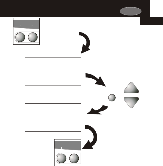
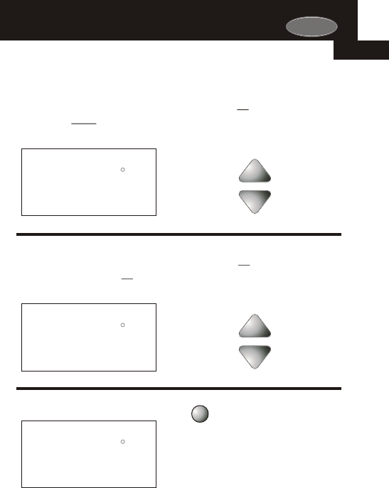
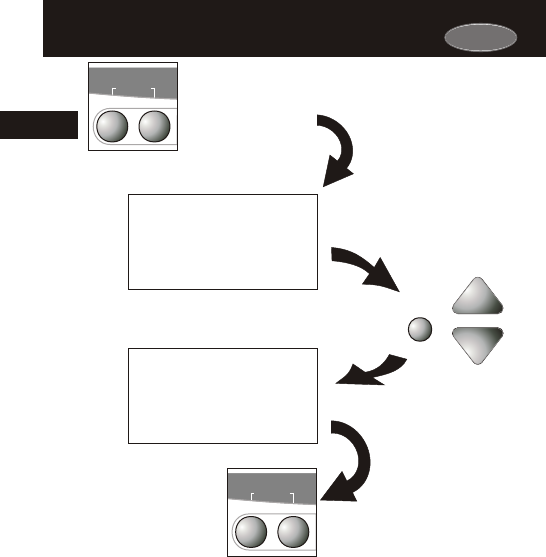
Buttons.
To adjust the
Clock or Day use
Press the MODE and
HUMIDITY buttons
at the same time
Press the MODE
and HUMIDITY
buttons at the
same time to
return to normal
operation.
Mo
Setup
2
Am
I2:00
Setup
I
Setting the Clock Setting the Clock
During Setup & Programming:
Pressing the UP or DOWN
buttons will modify the flashing
selection.
Setting the DaySetting the Day
Press
MODE
HUMIDITYMODE
SET CLOCK
HUMIDITYMODE
SET CLOCK
Page 1.2
1
Carrier
Carrier
Selecting the Heat or Cool ModeSelecting the Heat or Cool Mode
Press
MODE
Press
MODE
Press
MODE
Press
MODE
HEAT
I2:00
Su
70
Pm
68
COOL
I2:00
Su
70
Pm
76
HEAT
COOL
AUTO
I2:00
Su
70
Pm
68
76
HEAT
COOL
I2:00
Su
Program On
70
Pm
68
76
OFF
I2:00
Su
70
Pm
occupied
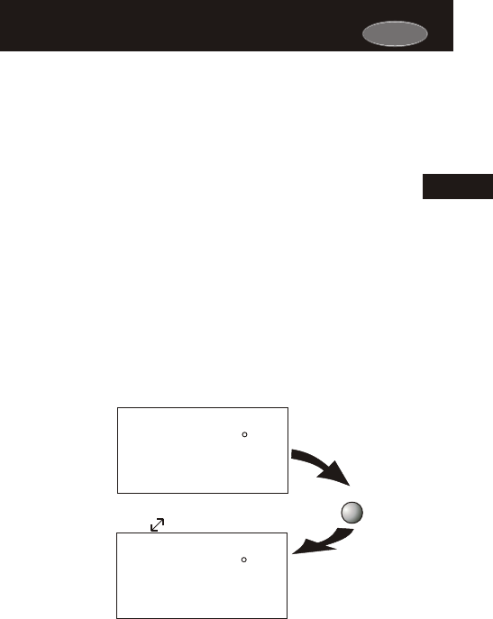
Program On will activate the
stored timer operation for the
heating and cooling
setpoints (occupied or
unoccupied periods).
Time Schedule for
Heating or Cooling
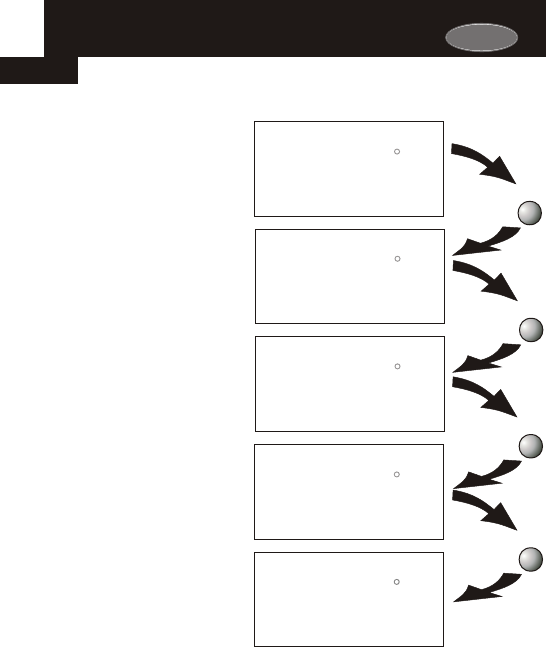
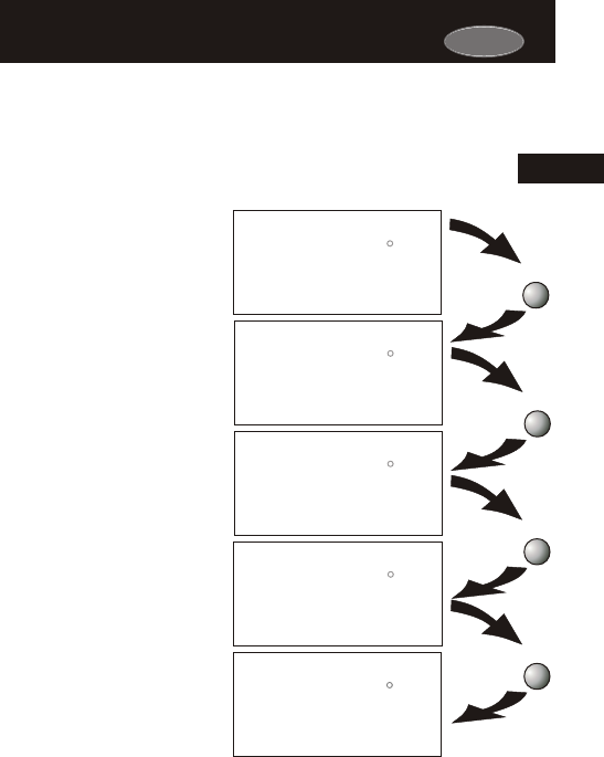
Select Mode by Pressing the MODE Button
1
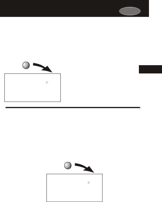
The HEAT setting indicates the
temperature the room has to
reach before the furnace will
turn on to heat the room.
Heating Only
The COOL setting indicates the
temperature the room has to
reach before the air conditioner
will turn on to cool the room.
Cooling Only
OFF indicates both heating
and air conditioning
systems are turned off.
Off
AUTO will automatically select
heat or cool based on room
temperature demand.
Heating or Cooling
Page 1.3
1
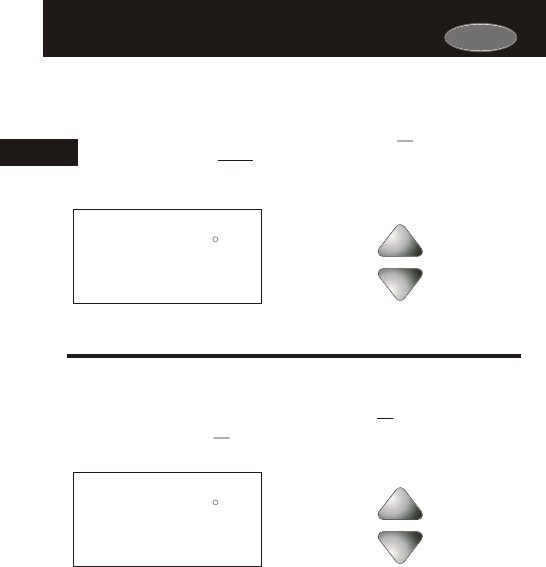
AUTO OR PROGRAM MODE
Pressing the UP or DOWN buttons in Auto or Program mode
will adjust both the heat and cool set temperatures
simultaneously.
buttons.
Adjust the desired
set temperature with the
HEAT
COOL
AUTO
I2:00
Su
70
Pm
68
76
HEAT OR COOL MODE
Pressing the UP or DOWN buttons in Heat or Cool mode will
adjust only the heat or cool set temperature.
buttons.
Adjust the desired
set temperature with the
COOL
I2:00
Su
70
Pm
76
Page 1.4
Selecting Your Desired Temperature
(adjusting the setpoints)
Selecting Your Desired Temperature
(adjusting the setpoints)
Press
FAN
HEAT
COOL
Su
70
Pm
68
76
I2:00
AUTO
FanOn
Using the Fan ButtonUsing the Fan Button
1
Fan On indicates constant fan operation.
If Fan On is selected the fan will run
continuously at all times, except in Off,
and will only run if there is a heating or
cooling demand in Unoccupied periods.
Pressing the FAN button toggles this
feature on or off.
Carrier

Section 2 Contents:
Front Panel Buttons.....................2.2
Display Features...........................2.3
Page 2.1
SECTION 2
Getting to Know Your ThermostatGetting to Know Your Thermostat
2
Carrier
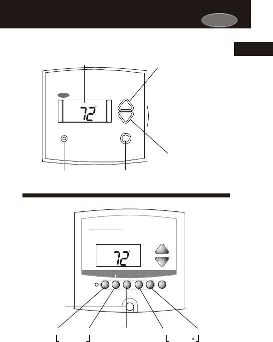
HUMIDITY FANMODE PROGRAM HOLIDAY OVER
RIDE
SET CLOCK OUTSIDE
HUMIDITY
AUTO
I2:00
Su
Pm
HEAT
COOL
72
74
FANMODE
SET CLOCK
PROGRAM HOLIDAY
OUTSIDE
Premier
Commercial
Programmable Thermostat
Backlit LCD Display
Override
Button
Heat or Cool Demand Indicator
Red = Heat, Green = Cool
Front Panel Front Panel
Page 2.2
2
Warmer Button
(glows red)
Cooler Button sometimes refer-
(glows blue) red to as the
DOWN button
[ ]
[ ]
sometimes referred
to as the UP button
AUTO
I2:00
Su
Pm
HEAT
COOL
72
74
Carrier
Carrier
QUICK RELEASE FOR
ACCESSORY PORT
(pg. 23.1)
AUTO
OFFON
Override
Unoccupied
Am
I8:88
SuMoTuWeThFrSa
Pm
AUXHEAT
COOL
FanOn
Service Filter
Pan UV Light
Program On
StartStop
DeHumidify
I88
Setup
Outside
Remote
88
L O
HI
88
123
2
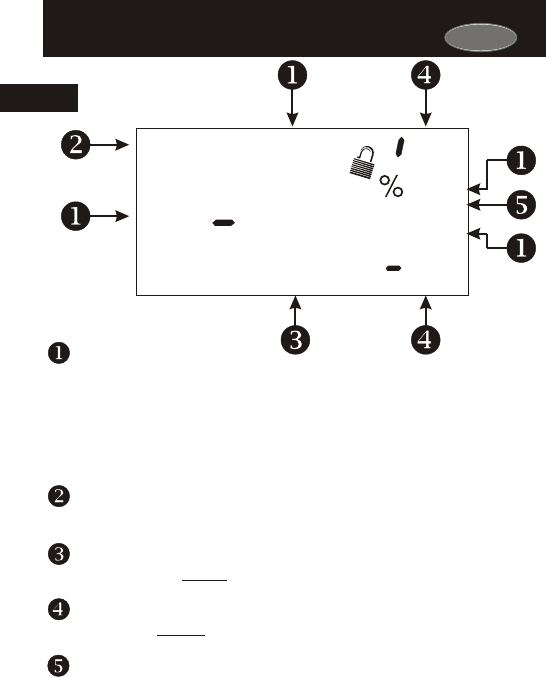
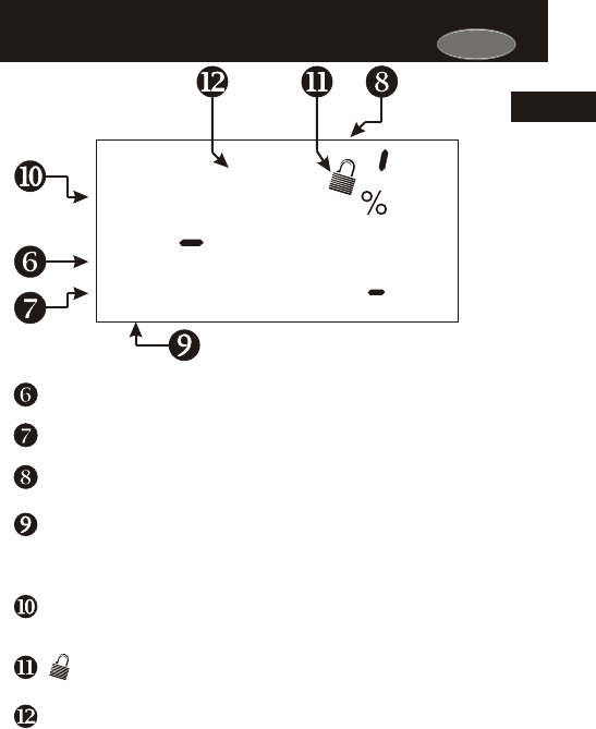
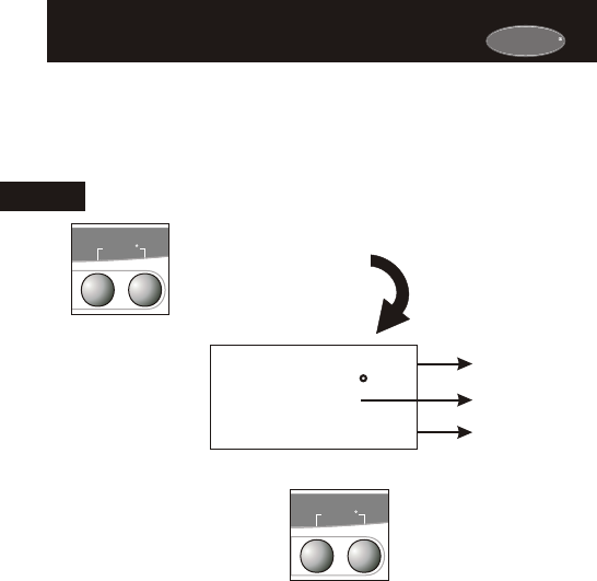
Display FeaturesDisplay Features
Mode Indicators - Section 4
Selects the operational mode of the equipment.
HEAT - Indicates the heating mode.
COOL - Indicates the air conditioning mode.
AUTO - Indicates the system will automatically changeover
between heat and cool modes as the temperature varies.
OFF - Indicates heating and cooling is turned off.
PROGRAM ON - Indicates the time period program is enabled to
run.
Clock with Day of the Week - Section 3
Indicates the current time and day. This clock is also used to program
the time period schedules.
Room Temperature Display - Section 5
Indicates the current room temperature and displays the outside
temperature when selected.
Desired Set Temperature - Section 4/5
Indicates desired room temperature(s). Also displays the highest
and lowest outside temperatures for the day.
Outside icon - Section 5
Indicates the temperature displayed is from the optional outside
sensor. Page 2.3
2
Carrier
AUTO
OFFON
Override
Unoccupied
Am
I8:88
SuMoTuWeThFrSa
Pm
AUXHEAT
COOL
FanOn
Service Filter
Pan UV Light
Program On
StartStop
DeHumidify
I88
Setup
Outside
Remote
88
L O
HI
88
123
2
Page 2.4
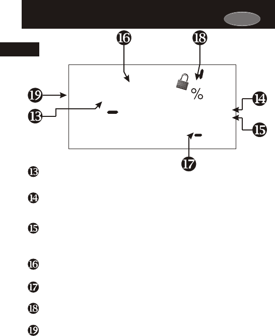
Display FeaturesDisplay Features
Occupied & Unoccupied icons - Section 6
Indicates the program number: Occupied 1,2,3,or Unoccupied.
Override icon - Section 6
Indicates the program is currently being overridden for up to 4 hours.
Setup icon - Sections 7-20
Indicates the thermostat is in the setup mode.
Fan On icon - Section 7
Indicates constant, continuous fan operation. When Fan On is not
lit - indicates the fan will only operate when necessary to heat or to
cool.
Service Filter icon - Section 19
Appears when the filter should be serviced under normal conditions.
Adjustable from 0 - 1950 hours of blower operation.
icon - Section 8
Indicates keypad has been locked.
StartStop icon -
Appears when programming occupied time periods.
Section 6
2
Carrier
Remote icon - Page 22.4
Indicates the remote sensor reading of the thermostat is being
viewed.
AuxHeat icon - Pages
Indicates 2nd stage electric strip heat is being used when the therm-
ostat is programmed for Heat Pump operation. Only the Aux icon
will appear during Cool to Dehumidify to indicate Reheat operation.
Humidify/DeHumidify icon -
Indicates the system is currently humidifying/dehumidifying the air.
Lo icon -
Indicates the lowest recorded outside temperature for the day.
10.5 & 13.4
Sections 9-10
Section 5
Hi icon - Section 5
Indicates the highest recorded outside temperature for the day.
Service Pan icon - Section 16
Indicates that a sensor (accessory) has detected the condensate
drain pan is full and the compressor (Y1) has been locked out.
AUTO
OFFON
Override
Unoccupied
Am
I8:88
SuMoTuWeThFrSa
Pm
AUXHEAT
COOL
FanOn
Service Filter
Pan UV Light
Program On
StartStop
DeHumidify
I88
Setup
Outside
Remote
88
L O
HI
88
123
Page 2.5
Display FeaturesDisplay Features
UV Light icon - Section 11/19
Appears when the UV bulb should be serviced under normal
conditions. Adjustable from 0 - 1950 days of operation.
2
Carrier

Page 3.1
Section 3 Contents:
Setting the Clock..........................3.2
Setting the Day.............................3.2
Note: During setup & programming pressing the UP or DOWN
buttons will modify the flashing selection.
SECTION 3
Setting the Clock and DaySetting the Clock and Day
3
Carrier
Carrier
Buttons.
To adjust the
Clock or Day use
Page 3.2
Mo
Setup
2
Am
I2:00
Setup
I
Setting the Clock Setting the Clock
Setting the DaySetting the Day
Press
MODE
HUMIDITYMODE
SET CLOCK
HUMIDITYMODE
SET CLOCK
Press the MODE and
HUMIDITY buttons
at the same time
Press the MODE
and HUMIDITY
buttons at the
same time to
return to normal
operation.
During Setup & Programming:
Pressing the UP or DOWN
buttons will modify the flashing
selection.
3

Section 4 Contents:
Programming for Auto or
Program Operation....................4.2
Selecting the Proper
Operating Mode.........................4.3
Selecting Your Desired
Temperature...............................4.7
Page 4.1
Note: During setup & programming pressing the UP or DOWN
buttons will modify the flashing selection.
SECTION 4
Basic OperationBasic Operation
4
Carrier
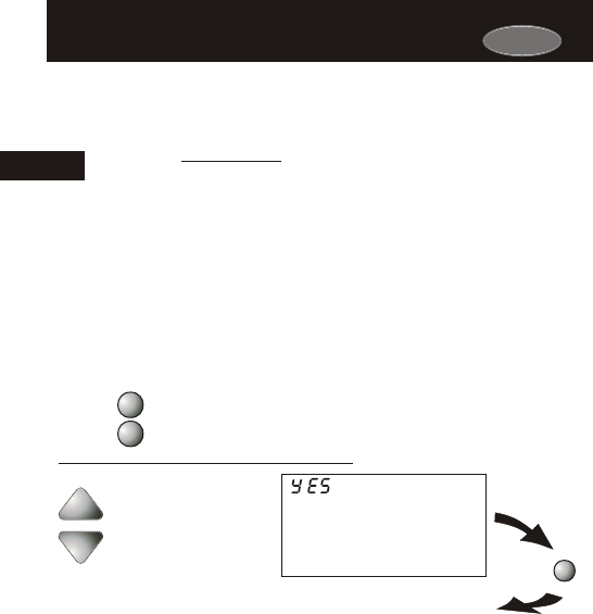
Page 4.2
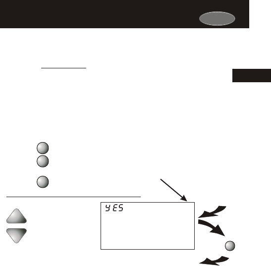
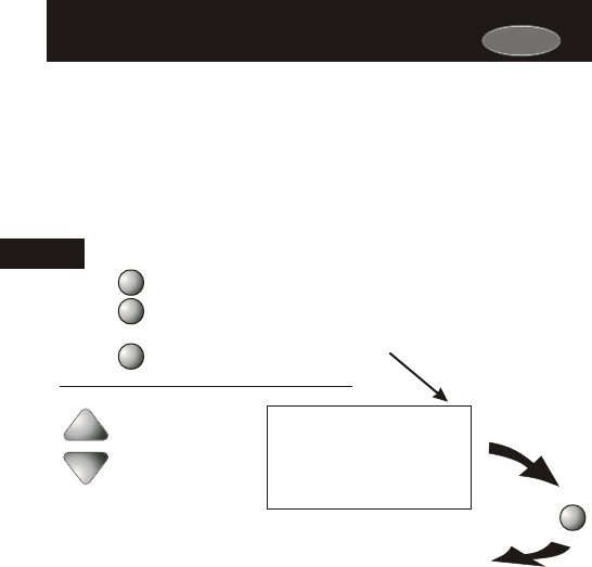
Select Yes if you would like
the thermostat to be program-
mable or No for non-program-
mable.
YES
NO
i
Program On Setup
PROGRAM
Press
Programmable or Non-Programmable
Thermostat
Programmable or Non-Programmable
Thermostat
PROGRAM
MODE
Note: Press the MODE
button momentarily
to move through the
setup screens. Press
and hold the MODE
button to move back-
wards through the
setup screens.
Press the PROGRAM button to leave the Setup screens. If no buttons are
pressed, the display will leave the setup screens after 30 seconds.
Press the MODE button. While holding
the MODE, press the PROGRAM
button to enter Setup screens.
If ‘NO’ is selected, the thermostat will lockout the Program On screen;
only the Off, Heat, Cool, and Auto screens may be accessed by
pressing the MODE button.
Select ‘YES’ if you would like your thermostat to be programmable,
then the Program mode will be accessible through the use of the
MODE button.
4When the very simplest operation is desired, this thermostat
may be configured to be non-programmable, with or without
Auto-Changeover. Follow the step below.
Carrier
Page 4.3
YES
NO
2
AUTO
Setup
PROGRAM
Press
PROGRAM
MODE
MODE
Press the PROGRAM button to leave the Setup screens. If no buttons are
pressed, the display will leave the setup screens after 30 seconds.
Manual or Auto-Changeover
Thermostat
Manual or Auto-Changeover
Thermostat
Press the MODE button. While holding
the MODE, press the PROGRAM
button to enter Setup screens.
Press the MODE button repeatedly
until this setup screen appears.
When the very simplest operation is desired, this thermostat may
be configured to be a manual heat and cool thermostat, with or
without time period programmability. Follow the step below.
The thermostat may be programmed to function as a Heat Only or
Cool Only thermostat by selecting ‘NO’ in the setup screen below.
This will lockout the Auto-Changeover screen and only allow the Off,
Heat, Cool, and Program On screens to be accessed.
Select Yes if you would
like the thermostat to
be Auto-Changeover or
No for a Heat Only and
Cool Only Thermostat.
4
Note: Press the MODE
button momentarily
to move through the
setup screens. Press
and hold the MODE
button to move back-
wards through the
setup screens.
Carrier
Press
MODE
Press
MODE
HEAT
I2:00
Su
70
Pm
68
COOL
I2:00
Su
70
Pm
76
OFF
I2:00
Su
70
Pm
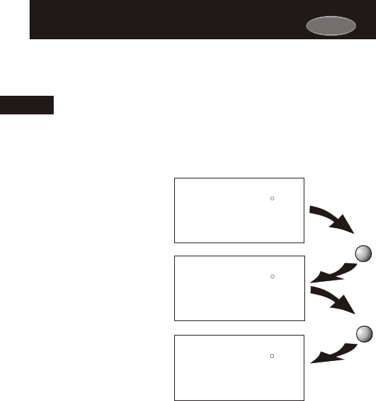
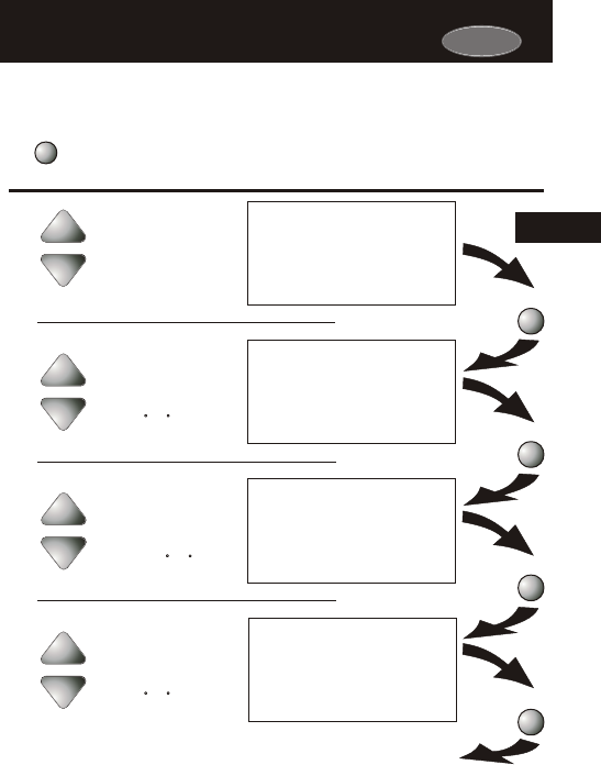
NON-PROGRAMMABLE WITH MANUAL-CHANGEOVER - If the
thermostat is configured to be a non-programmable thermostat with
Manual-Changeover, the following screens will be available by
pressing the MODE button.
Page 4.4
The HEAT setting indicates the
temperature the room has to
reach before the furnace will
turn on to heat the room.
Heating Only
The COOL setting indicates the
temperature the room has to
reach before the air conditioner
will turn on to cool the room.
Cooling Only
OFF indicates both heating
and air conditioning
systems are turned off.
Off
Operating Mode when the Thermostat
is Configured to be:
Operating Mode when the Thermostat
is Configured to be:
Select the Mode by Pressing the MODE Button
4
Carrier
Press
MODE
Press
MODE
Press
MODE
HEAT
I2:00
Su
70
Pm
68
COOL
I2:00
Su
70
Pm
76
HEAT
COOL
AUTO
I2:00
Su
70
Pm
68
76
OFF
I2:00
Su
70
Pm
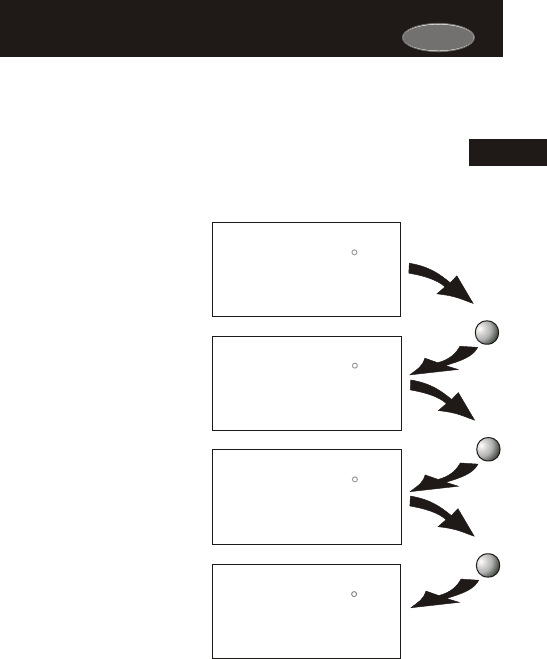
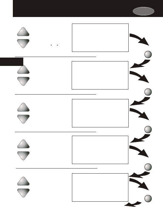
NON-PROGRAMMABLE WITH AUTO-CHANGEOVER - If the
thermostat is configured to be a non-programmable thermostat
with Auto-Changeover, the following screens will be available by
pressing the MODE button
Page 4.5
The HEAT setting indicates the
temperature the room has to
reach before the furnace will
turn on to heat the room.
Heating Only
Select the Mode by Pressing the MODE Button
The COOL setting indicates the
temperature the room has to
reach before the air conditioner
will turn on to cool the room.
Cooling Only
AUTO will automatically select
heat or cool based on room
temperature demand.
Heating or Cooling
OFF indicates both heating
and air conditioning
systems are turned off.
Off
Operating Mode when the Thermostat
is Configured to be:
Operating Mode when the Thermostat
is Configured to be:
4
Carrier
Press
MODE
Press
MODE
Press
MODE
Press
MODE
HEAT
I2:00
Su
70
Pm
68
COOL
I2:00
Su
70
Pm
76
OFF
I2:00
Su
70
Pm
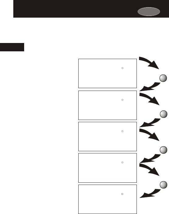
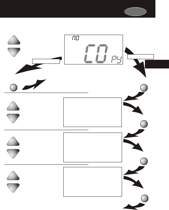
PROGRAMMABLE WITH MANUAL-CHANGEOVER - If the thermostat is
configured to be a programmable thermostat with Manual-Changeover, the
following screens will be available by pressing the MODE button.
Page 4.6
The HEAT setting indicates the
temperature the room has to
reach before the furnace will
turn on to heat the room.
Heating Only
The COOL setting indicates the
temperature the room has to
reach before the air conditioner
will turn on to cool the room.
Cooling Only
OFF indicates both heating
and air conditioning
systems are turned off.
Off
HEAT
I2:00
Su
70
Pm
68
Program On
occupied
1
The HEAT Program On setting
will activate the time period
program for the heating
setpoint ONLY (occupied or
unoccupied periods).
Time Schedule for
Heating Only
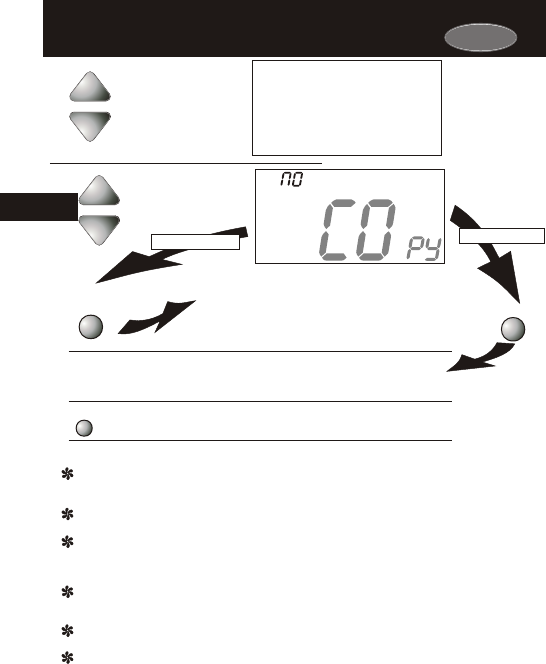
COOL
I2:00
Su
Program On
70
Pm
76
occupied
1
The COOL Program On setting
will activate the time period
program for the cooling
setpoint ONLY (occupied or
unoccupied periods).
Time Schedule for
Cooling Only
4
Operating Mode when the Thermostat
is Configured to be:
Operating Mode when the Thermostat
is Configured to be:
Select the Mode by Pressing the MODE Button
Carrier
Carrier
Program On will activate the
time period program for the
heating and cooling
setpoints. (occupied or
unoccupied periods)
Time Schedule for
Heating or Cooling
HEAT
COOL
I2:00
Su
Program On
70
Pm
68
76
occupied
1
PROGRAMMABLE WITH AUTO-CHANGEOVER - If the thermostat is
configured to be a programmable thermostat with Auto-Changeover,
the following screens will be available by pressing the MODE button.
Press
MODE
Press
MODE
Press
MODE
Press
MODE
I2:00
Su
70
Pm
HEAT
68
COOL
I2:00
Su
70
Pm
76
HEAT
COOL
AUTO
I2:00
Su
70
Pm
68
76
OFF
I2:00
Su
70
Pm
Page 4.7
The HEAT setting indicates the
temperature the room has to
reach before the furnace will
turn on to heat the room.
Heating Only
The COOL setting indicates the
temperature the room has to
reach before the air conditioner
will turn on to cool the room.
Cooling Only
AUTO will automatically select
heat or cool based on room
temperature demand.
Heating or Cooling
OFF indicates both heating
and air conditioning
systems are turned off.
Off
Operating Mode when the Thermostat
is Configured to be:
Operating Mode when the Thermostat
is Configured to be:
Select the Mode by Pressing the MODE Button
4
Page 4.8
AUTO OR PROGRAM MODE
Pressing the UP or DOWN buttons in Auto or Program
modes will adjust both the heat and cool set temperatures
simultaneously. For more information on this see page 13.2.
buttons.
Adjust the desired
set temperature with the
HEAT
COOL
AUTO
I2:00
Su
70
Pm
68
76
HEAT OR COOL MODE
Pressing the UP or DOWN buttons in Heat or Cool modes will
adjust only the heat or cool set temperature.
buttons.
Adjust the desired
set temperature with the
COOL
I2:00
Su
70
Pm
76
Selecting Your Desired Temperature (adjusting setpoints)Selecting Your Desired Temperature (adjusting setpoints)
4
Carrier

Section 5 Contents:
Viewing the Outside
Temperature..............................5.2
Viewing the Indoor
Humidity....................................5.3
Page 5.1
SECTION 5
Viewing the Temperature and Humidity SensorsViewing the Temperature and Humidity Sensors
5
Carrier
Carrier
The highest and lowest
temperatures for the day
will be displayed along
with the current outside
temperature.
This reading is from the
sensor connected to RS2.
83
Outside
68
L O
HI
92
Requires an outside sensor (optional accessory) to be installed (see
page 15.2 for wiring instructions). To read the temperature from the
outside sensor, press the PROGRAM and HOLIDAY buttons. The
display will then show the current outside temperature along with the
highest and lowest temperatures for the day.
Page 5.2
Viewing the Outside TemperatureViewing the Outside Temperature
Press the PROGRAM
button. While holding
PROGRAM, press the
HOLIDAY button to view
the Outside temperature.
Press the PROGRAM
button. While holding
PROGRAM, press the
HOLIDAY button to leave
the Outside temperature
screen.
High temperature
for the day.
Low temperature
for the day.
Current outside
temperature.
PROGRAM HOLIDAY
OUTSIDE
PROGRAM HOLIDAY
OUTSIDE
5
Note: If no sensors are connected 2 dashes [- -] will appear.
Carrier
To view the indoor humidity
reading, press the
HUMIDITY button
HUMIDITY
Press
HUMIDITY
40
Humidify
Setup
I
Current Room Humidity
Requires the Humidity Module (optional accessory) to be installed.
To display the current humidity at the thermostat, press the
HUMIDITY button. The display will then show the current indoor
humidity along with the humidification setpoint (Section 9).
Note: The humidity reading will not appear unless the Humidity
Module has been installed. If the Humidity Module has not been
installed dashes will appear in place of the humidity reading.
Press the HUMIDITY button
again to return the display
to normal operation.
Page 5.3
Viewing the Indoor HumidityViewing the Indoor Humidity
0
NOTE: Due to variations in environmental conditions, it is not always possible
to achieve the desired humidification or dehumidification setpoint.
5

Section 6 Contents:
Programming a Daily
Schedule...................................6.2
Overriding the Daily
Schedule...................................6.6
Page 6.1
SECTION 6
Programming the Daily ScheduleProgramming the Daily Schedule
6
Carrier
Carrier
Press the PROGRAM button to enter time period programming.
Continued
Use the Programming Worksheet on the back cover
to help with this section.
Press
PROGRAM
Page 6.2
Programming a Daily ScheduleProgramming a Daily Schedule
Press
MODE
Press
MODE
Press
MODE
Press
MODE
occupied
COOL
74
occupied
HEAT
COOL
72
74
Unoccupied
COOL
85
Select the maximum # of
occupied periods to be
used on any one day.
Typically most installations
use only Occupied 1.
(1,2 or 3)
Adjust the cooling
setpoint for Occupied 1.
Adjust the heating
setpoint for Occupied 1.
Adjust the cooling
setpoint for unoccupied
periods.
occupied
1
1
1
(35 - 99, OF )
(OF, 35 - 99 )
(35 - 99, OF )
6
Carrier
Continued
Press
MODE
Press
MODE
Press
MODE
Press
MODE
Press
MODE
Page 6.3
Unoccupied
HEAT
55
occupied
Mo
occupied
Am
7:00
Mo
Start
occupied
6:00
Mo
Pm
Stop
ON
occupied
Mo
Adjust the heating set-
point for Unoccupied
periods.
Select the day for
Occupied 1.
(Mo - Su)
Adjust the start time
for Occupied 1.
Adjust the stop time
for Occupied 1.
Select Occupied 1 to run
on this day (On), or not to
run on this day (Off).
Off
On
(OF, 35 - 99 )
1
1
1
1
6
COOL
85
Select Yes to copy the
previous day’s program
to this day.
Yes
No
If Yes is selected:
If No is selected:
The copy command becomes available after the maximum # of
occupied periods are programmed in a day. This example uses
only one occupied period.
Press
MODE
Tu
Page 6.4
occupied
Tu
Continued
Press
MODE
Press
MODE
Press
MODE
Press
MODE
occupied
Am
7:00
Tu
Start
occupied
6:00
Tu
Pm
Stop
Select the day
for Occupied 1.
(Tu - M)
Adjust the start time
for Occupied 1.
Adjust the stop time
for Occupied 1.
1
1
1
Selecting Yes, then pressing mode will copy the
previous day’s program. If yes is selected again,
or each time, this routine will repeat.
6
Carrier
Carrier
Page 6.5
If Yes is selected: If No is selected:
Press
MODE
Select Yes to copy
the previous day’s
program to this day.
Yes
No
We
Press
MODE
If No is selected, as in previous steps, flashing prompts will appear to input start
and stop times for Occupied 1. If more than one occupied period was selected in
the first programming step (page 6.2), then the cool and heat setpoints, and start
and stop times for each additional occupied period will be prompted.
ON
occupied
Tu
Select Occupied 1 to run
on this day (On), or not to
run on this day (Off).
Off
On
1
Selecting Yes, then pressing mode will copy the
previous day’s program. If yes is selected each
time, this routine will repeat.
6
PROGRAMMING TIPS
If only the Occupied 1 period is selected in the first programming step (page 6.2), Occupied
2 & 3 programming steps are skipped. Furthermore, if Occupied 2 is selected, Occupied 3
programming steps are skipped.
Heat & Cool setpoints for Occupied 1 are the same for every day of the week. If desired,
Heat & Cool setpoints for Occupied 2 & 3 can be adjusted differently for each day of the week.
If the start time is set later in the day than the stop time, the program will run from the start
time to midnight and from midnight to the stop time on the same day. For example: 9pm start,
8am stop, on Monday. In this example the program will run from 12am Monday to 8am Monday
and again from 9pm Monday to 12am Tuesday.
Unoccupied Operation: The unoccupied settings take effect at all times when: (1) the program is
on and (2) the current time is outside a preset occupied period. For this reason start and stop
times are not necessary for unoccupied time periods.
If the same start and stop times are programmed for an occupied period, then it will run
24 hours.
If one occupied period starts and stops within another occupied period the lower occupied # has
priority. For example: If Occupied 3 is programmed to be on 24 hours, and Occupied 2 is
programmed to run that day, then the Occupied 2 setting will take over for Occupied 3 between
Occupied 2 start and stop times.
After programming for all seven days is complete, press the PROGRAM button to
leave the Setup screens. If no buttons are pressed, the display will leave the setup
screens after 30 seconds.
Press
PROGRAM
Carrier
Page 6.6
Overriding the Daily ScheduleOverriding the Daily Schedule
Unoccupied
7:56
We
Pm
HEAT
COOL
Program On
65
55
85
Override
occupied
30
Pm
HEAT
COOL
Program On
65
72
74
The OVERRIDE button may be used to interrupt the normal time
schedule programming of the thermostat. Override may only be used
when the thermostat is running the time schedule, in Program On
mode.
Press
OVERRIDE
7:56
:
We
1
6
Unoccupied Operation - During programmed, unoccupied
periods, pressing the OVERRIDE button will temporarily
force the thermostat into Occupied 1 comfort settings for 30
minutes. The remaining Override time will alternate with the
clock (refer to the second display below). The Override timer
can be set up to a maximum of four (4:00) hours, in increments
of 30 minutes. If the timer has been set for the maximum time,
the next press of the OVERRIDE button will reset the timer,
returning the thermostat to the correct time period program for
the day.
Occupied Operation - During programmed, occupied periods, a
press of the OVERRIDE button will force the thermostat into an
unoccupied period for the remainder of the day. During this
forced unoccupied period the OVERRIDE button will operate as
described above.

Section 7 Contents:
Using the Fan Button.................7.2
Smart Fan Operation..................7.2
Setting the Fan-Off Time
Delay..........................................7.3
Fan Purge Operation..................7.4
Page 7.1
SECTION 7
Programming the Fan OperationProgramming the Fan Operation
7
Carrier
Carrier
When the fan is set for automatic operation it will energize any time
there is a call for heating or cooling, otherwise the fan will remain off.
Pressing the FAN button will energize the fan and display the FanOn
icon on the thermostat display. To operate the fan in the automatic
mode, press the FAN button again and the FanOn icon will disappear.
Press
FAN
HEAT
COOL
AUTO
Su
70
Pm
68
76
I2:00
FanOn
Page 7.2
Using the Fan ButtonUsing the Fan Button
7
Fan On indicates constant fan operation.
If Fan On is selected the fan will run
continuously at all times, except in Off,
and will only run if there is a heating or
cooling demand in Unoccupied periods.
Pressing the FAN button toggles this
feature on or off.
This feature allows the fan to run continuously during Occupied 1, 2
or 3 and automatically de-energize during Unoccupied, except when
necessary to heat or cool. To use this feature, place the thermostat in
the Program On mode. Next, press the FAN button to display the
FanOn icon (see below).
Smart Fan OperationSmart Fan Operation
Press
FAN
HEAT
COOL
I2:00
Su
Program On
70
Pm
68
76
occupied
1
FanOn
Set the Fan Off Delay
to 0, 30, 60, or 90
seconds.
FanOn
Setup
3
Press the PROGRAM button to leave the Setup screens. If no buttons are
pressed, the display will leave the setup screens after 30 seconds.
PROGRAM
Press
Page 7.3
Setting the Fan-Off Time DelaySetting the Fan-Off Time Delay
To increase cooling efficiency of your unit, the thermostat may be
programmed to continue running the fan after a call for cooling has
been satisfied. This delay may be set for 30, 60, or 90 seconds. If
the Fan Off Delay is set for zero seconds, the fan will not energize
after a call for cooling has been satisfied.
:00
7
PROGRAM
MODE
MODE
Press the MODE button. While holding
the MODE, press the PROGRAM
button to enter Setup screens.
Press the MODE button repeatedly
until this setup screen appears.
Note: Press the MODE
button momentarily
to move through the
setup screens. Press
and hold the MODE
button to move back-
wards through the
setup screens.
Carrier
Carrier
When this feature is activated, the fan will turn on during an
unoccupied period at a preset amount of time prior to Occupied 1.
This preoccupancy fan purge timer may be set from zero to three
hours, in 15 minute increments. Zero means this feature is turned off.
Press the PROGRAM button to leave the Setup screens. If no buttons are
pressed, the display will leave the setup screens after 30 seconds.
PROGRAM
Press
Page 7.4
Fan Purge OperationFan Purge Operation
Adjust the preoccupancy
fan purge timer.
0 - 3 hours.
0:00 = off
0:00
Setup
4
7
PROGRAM
MODE
MODE
Press the MODE button. While holding
the MODE, press the PROGRAM
button to enter Setup screens.
Press the MODE button repeatedly
until this setup screen appears.
Note: Press the MODE
button momentarily
to move through the
setup screens. Press
and hold the MODE
button to move back-
wards through the
setup screens.

Section 8 Contents:
Turning On/Off the
Backlight...................................8.2
Programming the Thermostat
to Display Temperature in
Fahrenheit or Celsius..............8.2
Locking/Unlocking the
Keypad......................................8.3
Programming a Security
Level..........................................8.4
Page 8.1
SECTION 8
Thermostat Display OptionsThermostat Display Options
8
Carrier
Carrier
Press the PROGRAM button to leave the Setup screens. If no buttons are
pressed, the display will leave the setup screens after 30 seconds.
Press
MODE
PROGRAM
Press
Page 8.2
Turning On/Off the BacklightTurning On/Off the Backlight
PROGRAM
MODE
MODE
Press the MODE button. While holding
the MODE, press the PROGRAM
button to enter Setup screens.
Press the MODE button repeatedly
until this setup screen appears.
Note: Press the MODE
button momentarily
to move through the
setup screens. Press
and hold the MODE
button to move back-
wards through the
setup screens.
5
Setup
Select backlight operation:
AUTO - Light from 6pm to
6am nightly.
ON - Light continuously.
OFF - Light for 8 seconds
after a button press.
AUTO
Select thermostat
operation in degrees
Fahrenheit or Celsius.
C
F
f
6
Setup
Programming the Thermostat to Display
Temperature in Fahrenheit or Celsius
Programming the Thermostat to Display
Temperature in Fahrenheit or Celsius
8
Page 8.3
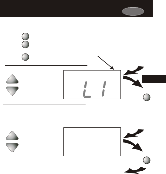
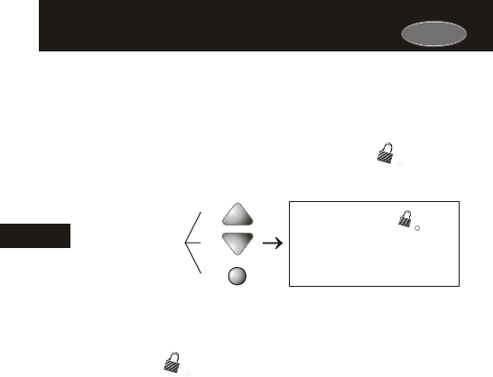
To prevent unauthorized use of the thermostat, the front panel
buttons may be disabled. To disable, or ‘lock’ the keypad, press
and hold the MODE button. While holding the MODE button,
press the UP and DOWN buttons together. The icon will
appear on the display, then release the buttons.
Press all three
buttons in the order
outlined above for
keypad lockout
MODE
HEAT
COOL
65
I2:00
Pm
55
85
Locking/Unlocking the KeypadLocking/Unlocking the Keypad
To unlock the keypad, press and hold the MODE button. While
holding the MODE button, press the UP and DOWN buttons
together. The icon will disappear from the display, then
release the buttons.
8
Carrier
AUTO
Carrier
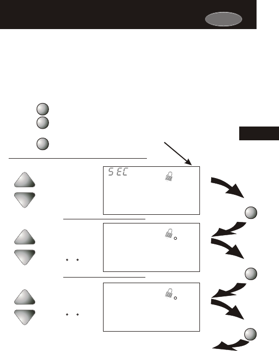
Select the security level:
0=No security in effect
1=Setpoint range limited
2=1+ program on all times
3=2 + prohibits setpoint
changes
Adjust the minimum
allowable cool setpoint
when security is in effect.
(35 - 99 )
Press
MODE
Press
MODE
Press the PROGRAM button to leave the Setup screens. If no buttons are
pressed, the display will leave the setup screens after 30 seconds.
PROGRAM
Press
When a security level has been programmed, the thermostat will allow
limited adjustment to the setpoints (steps # 8 and 9). In security
levels 2 and 3, the thermostat is forced into the Program On mode.
To disable the security feature, set the value in step #7 to 0; this will
cause steps # 8 and 9 not to appear.
Page 8.4
Programming a Security LevelProgramming a Security Level
0
Setup
7
HEAT
80
Setup
HI
8
COOL
65
Setup
LO
9
Adjust the maximum
allowable heat setpoint
when security is in effect.
(35 - 99 )
Step #8 appears only
if step #7 is not 0.
Step #9 appears only
if step #7 is not 0.
8
PROGRAM
MODE
MODE
Press the MODE button. While holding
the MODE, press the PROGRAM
button to enter Setup screens.
Press the MODE button repeatedly
until this setup screen appears.
Note: Press the MODE
button momentarily
to move through the
setup screens. Press
and hold the MODE
button to move back-
wards through the
setup screens.

Page 9.1
Additionally, the manufacturer of this thermostat is not responsible
for the fitness of the humidifier and/or installation of said humidifier
connected to this thermostat. Furthermore, the maintenance of the
humidifier components, including but not limited to, the filters and
pads are not the responsibility of the thermostat manufacturer.
The Humidifier Service icon is only a suggestive reminder and
should not take the place of the humidifier manufacturer’s
required maintenance requirements and schedule.
Disclaimer:
The manufacturer of this thermostat cannot be liable for
misinstallation, improper connection or improper programming of
the humidity functions of this thermostat that may result in water
damage or mold growth.
Section 9 Contents:
Installing the Humidity
Module.......................................9.2
Setting a Thermostat Jumper
for Humidity Operation............9.3
Adjusting the Humidification
Setpoint.....................................9.4
NOTE: The humidification functions described in this section will
only be available if a Humidity Module has been properly installed.
SECTION 9
HumidificationHumidification
9
Carrier
Page 9.2
9
Figure 2
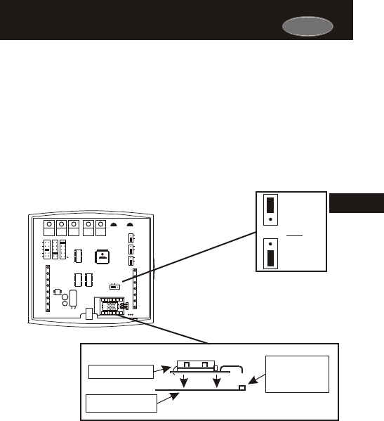
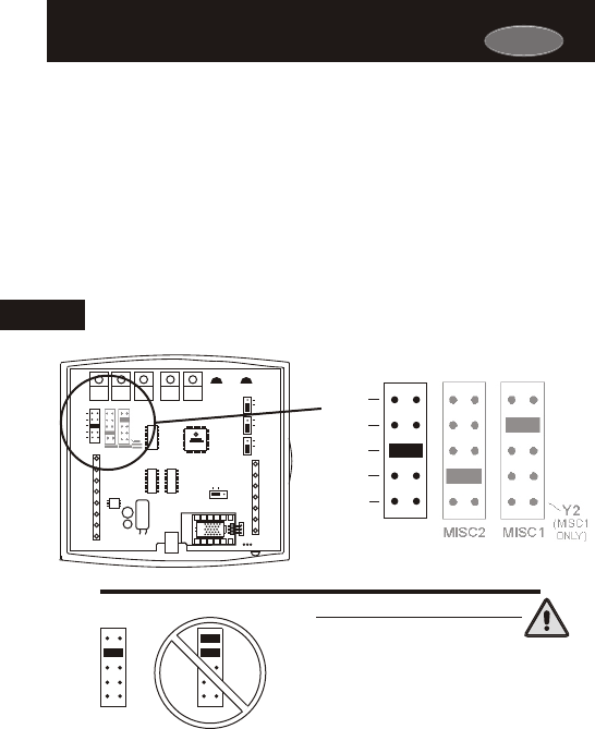
Installing the Humidity ModuleInstalling the Humidity Module
For proper humidity operation, this
jumper must be set for HUM.
HUM
NO HUM
OR
To install the Humidity Module the thermostat must be detached
from the back plate. Plug the Humidity Module into the Humidity
Module connector as shown in Figure 2 below. Follow the detailed
instructions included with the Humidity Module accessory. Once the
Humidity Module has been installed, you must adjust the Humidity
jumper setting to HUM as shown in Figure 1 below. This will allow
you to access the humidification and dehumidification setup steps.
HP
GAS
B
O
ELEC
GAS
(FAN)
W1
Y1
G
R
C
MISC2
W2
MISC1
Rs2
RSGND
MISC3
RS+5
Rs1
W3
HUM
DEHUM
MISC3 MISC2 MISC1
Y2
(MISC1
ONLY)
INSTALL HUMIDITY
MODULE WITH SENSING
ELEMENT OUTWARD
HUM
NO HUM
1
2
4
6
8
X
Z
1
5
7
9
Y
3
Humidity Module
Thermostat Circuit
Board.
Humidity Module
Plug located on
the Thermostat
Circuit Board.
Install the Humidity Module
(see Humidity Module Instruction
Sheet for more detailed information).
Figure 1
PROG
CK1
CKGND
ECON
Back of 33CS450-01
Carrier
ECON
Page 9.3
Setting a Thermostat Jumper for
Humidity Operation
Setting a Thermostat Jumper for
Humidity Operation
NEVER PUT MORE THAN ONE JUMPER
ON THE SAME MISC JUMPER BLOCK!
THIS MAY DAMAGE THE THERMOSTAT
To operate one of the MISC outputs using humidity-based operation,
place the MISC1, MISC2, or MISC3 jumper on the terminal labeled
HUM (see diagram below). This will supply 24VAC to the selected
MISC terminal based on the humidification programming in the
following pages. Only one of the three outputs (MISC1, MISC2, or
MISC3) is required to have this jumper. For more information
regarding the MISC1, MISC2, and MISC3 outputs, please see
section 21.
MISC3 MISC3
OK
In the diagram below, the MISC3 jumper
has been set for HUM (humidify) operation.
W3
PROG
HUM
DEHUM
MISC3 MISC2 MISC1
Y2
(MISC1
ONLY)
9
IMPORTANT CAUTION
HP
GAS
B
O
ELEC
GAS
(FAN)
W1
Y1
G
R
C
MISC2
W2
MISC1
RS2
RSGND
MISC3
RS+5
Rs1
W3
HUM
DEHUM
MISC3 MISC2 MISC1
Y2
(MISC1
ONLY)
INSTALL HUMIDITY
MODULE WITH SENSING
ELEMENT OUTWARD
HUM
NO HUM
1
2
4
6
8
X
Z
1
5
7
9
Y
3
PROG
CK1
CKGND
ECON
Carrier
Carrier
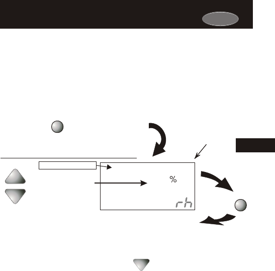
Press the HUMIDITY button to leave the
Humidity Control screens (if no buttons are
pressed, the display will leave the Humidity
Control screens after 30 seconds).
HUMIDITY
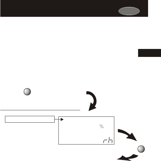
Adjust the desired
humidification setpoint
(0%-60%)
NOTE: Each step # is located at
the top right corner of the
display for easy reference.
Press
HUMIDITY
40
Humidify
0
Setup
I
Current Room Humidity
Page 9.4
If your HVAC unit is equipped with a humidification system and the
Humidity Module has been installed, the thermostat will provide power
to the appropriate terminal on the backplate of the thermostat when
the humidity in the building falls below the setpoint you have chosen.
The value for this setpoint ranges from 0% to 60%.
Adjusting the Humidification SetpointAdjusting the Humidification Setpoint
You cannot set the dehumidify setpoint any lower than the humidify setpoint; a
5% differential is forced between the humidify and dehumidify setpoints.
Press the HUMIDITY
button to enter the
Humidity Setup screen.
Humidification Notes: Press the button to set the humidity
setpoint to 0% for no humidification operation.
NOTE: Due to variations in environmental conditions, it is not always possible
to achieve the desired humidification or dehumidification setpoint.
9

Page 10.1
NOTE: The dehumidification functions described in this section will
only be available if a Humidity Module has been properly installed.
For instructions on installing the Humidity Module please see page 9.2.
Section 10 Contents:
Configuring a Thermostat Output
Jumper for Dehumidification
Operation................................10.2
Adjusting the Dehumidification
Setpoint...................................10.3
Using Your Air Conditioner
to Dehumidify.........................10.4
Using the Reheat
Function..................................10.5
Using the DEHUM
Terminal..................................10.6
SECTION 10
DehumidificationDehumidification
10
Carrier
Carrier
ECON
Page 10.2
Setting a Thermostat Jumper for
Dehumidification Operation
Setting a Thermostat Jumper for
Dehumidification Operation
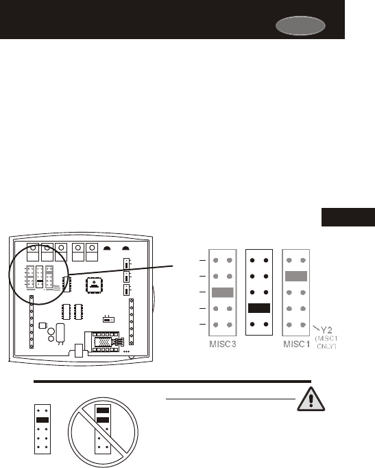
NEVER PUT MORE THAN ONE JUMPER
ON THE SAME MISC JUMPER BLOCK!
THIS MAY DAMAGE THE THERMOSTAT
MISC3 MISC3
OK
To control a MISC output for dehumidification, install the Humidity
Module and place the Humidity Jumper on HUM (see page 9.2).
Then place the MISC1, MISC2, or MISC3 jumper on the terminal
labeled DEHUM (see diagram below). This will supply 24VAC to the
selected MISC terminal based on the programming in the following
pages. Only one of the three outputs (MISC1, MISC2, or MISC3) is
required to have a jumper. For more information regarding the
MISC1, MISC2, and MISC3 outputs, please see section 21.
10
W3
PROG
HUM
DEHUM
MISC3 MISC2 MISC1
Y2
(MISC1
ONLY)
In the diagram below, the MISC2 jumper has
been set for DEHUM (dehumidification) operation.
IMPORTANT CAUTION
HP
GAS
B
O
ELEC
GAS
(FAN)
W1
Y1
G
R
C
MISC2
W2
MISC1
Rs2
RSGND
MISC3
RS+5
Rs1
W3
HUM
DEHUM
MISC3 MISC2 MISC1
Y2
(MISC1
ONLY)
INSTALL HUMIDITY
MODULE WITH SENSING
ELEMENT OUTWARD
HUM
NO HUM
1
2
4
6
8
X
Z
1
5
7
9
Y
3
PROG
CK1
CKGND
ECON
Carrier
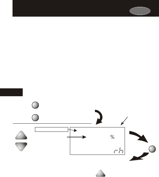
Press the HUMIDITY button to leave the Humidity
Control screens (if no buttons are pressed, the display
will leave the Humidity Control screens after 30 seconds).
Press the HUMIDITY button
to enter the Humidification
Setup screens.
HUMIDITY
Adjust the desired
dehumidification setpoint
(25%-99%)
NOTE: Each step # is located at
the top right corner of the
display for easy reference.
HUMIDITY
ON / +
OFF / -
40
DeHumidify
99
Setup
2
Current Room Humidity
Page 10.3
Adjusting the Dehumidification SetpointAdjusting the Dehumidification Setpoint
Press
Dehumidification Notes: Press the button to set the
dehumidification setpoint to 99% for no dehumidification operation.
This will lockout Advanced Setup steps 10, 11, and 12 (see pages
10.4 - 10.5).
You cannot set the dehumidify setpoint any lower than the humidify setpoint; a
5% differential is forced between the humidify and dehumidify setpoints.
Press the MODE button once
MODE
10 NOTE: Due to variations in environmental conditions, it is not always
possible to achieve the desired humidification or dehumidification setpoint.
Cool to Dehumidify: If the thermostat is programmed for Cool to
Dehumidify operation, then the thermostat will energize the cooling
system any time the humidity in the building is above the setpoint you
have chosen. The thermostat may also be programmed for Reheat
operation if available. See pages 10.4 and 10.5 for detailed
programming instructions.
Dehum Terminal: If a MISC terminal is selected for DEHUM operation
(see page 10.2), then the thermostat will provide power to this terminal
when the humidity in the building is above the setpoint you have chosen.
See page 10.6 for detailed programming instructions. To utilize this
feature your HVAC unit must be equipped with a DEHUM terminal.
In each case, when the indoor humidity falls below the setpoint you
have selected, Cool to Dehumidify and the MISC terminal will be
de-energized. The value for this setpoint ranges from 25% to 99%.
Carrier
Page 10.4
Using Your Air Conditioner to Dehumidify Using Your Air Conditioner to Dehumidify
Step 11 appears only if step 10 is set to “ON”
Select Cool to
Dehumidify feature.
On
Off
OFF
DeHumidify
Setup
I0
COOL
DeHumidify
3
Setup
I i
Press the PROGRAM button to leave the Setup screens. If no buttons are
pressed, the display will leave the setup screens after 30 seconds.
PROGRAM
Press
MODE
Press
Dehumidification Notes: The thermostat must be in the Cool, Auto, or
Program On mode for the Cool to Dehumidify feature to be available.
Adjust the maximum
overshoot of the set
temperature in Cool to
Dehumidify mode.
If Cool to Dehumidify is on and the Humidity Module is installed,
the thermostat has the ability to initiate a cooling cycle for advanced
dehumidification operation. When the thermostat detects the humidity
percentage is above the setpoint for dehumidification, and heating or
cooling is not on, the thermostat will force the compressor to run with
the fan, thus reducing moisture in the air. The green LED will blink
once every eight seconds to indicate this is taking place. This feature
will also allow you to adjust the cooling overshoot of the
0 to 5 (adjustable in step #11). For
setpoint, from
Example: If the cooling overshoot is
set for 3 F and the cooling setpoint is set for 74 F, then as long as the room
temperature reads between 71 F and 74 F this feature will energize the
compressor and fan to dehumidify the air.
°°
°°
°°
Steps 10 and 11 only appear if the Dehumidification
setpoint is not 99% (see page 10.3).
10
PROGRAM
MODE
MODE
Press the MODE button. While holding
the MODE, press the PROGRAM
button to enter Setup screens.
Press the MODE button repeatedly
until this setup screen appears.
Note: Press the MODE
button momentarily
to move through the
setup screens. Press
and hold the MODE
button to move back-
wards through the
setup screens.
(0 - 5 )
Carrier
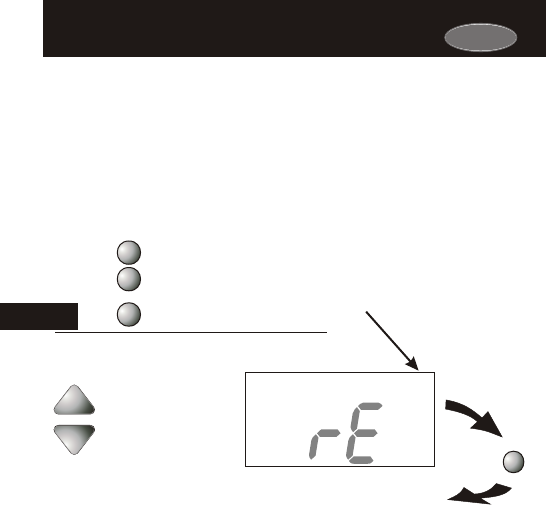
Page 10.5
Using the Reheat FunctionUsing the Reheat Function
This feature allows the thermostat to turn on Electric Heating (W2)
during Cool to Dehumidify to maintain room temperature until the
dehumidification setpoint is reached. The cooling cycle will allow for
the dehumidification of the air to occur while the Electric Heating will
allow for a constant room temperature. If Reheat is enabled the Aux
icon will appear on the display during Cool to Dehumidify operation.
Dehumidification Notes: Reheat is only available if Cool to
Dehumidify has been set to ON in step #10 (see page 10.4).
If Reheat operation is
desired during the
dehumidification process
select On; otherwise select
Off.
On
Off
HEAT
OFF
DeHumidify
Setup
I2
Press the PROGRAM button to leave the Setup screens. If no buttons are
pressed, the display will leave the setup screens after 30 seconds.
PROGRAM
Press
Step 12 appears only if step 10 is set to “ON” and if the
Dehumidification setpoint is not 99% (see page 10.3).
10
PROGRAM
MODE
MODE
Press the MODE button. While holding
the MODE, press the PROGRAM
button to enter Setup screens.
Press the MODE button repeatedly
until this setup screen appears.
Note: Press the MODE
button momentarily
to move through the
setup screens. Press
and hold the MODE
button to move back-
wards through the
setup screens.
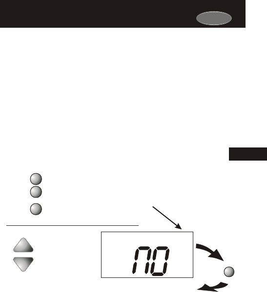
Page 10.6
Using the Dehum TerminalUsing the Dehum Terminal
Press the PROGRAM button to leave the Setup screens. If no buttons are
pressed, the display will leave the setup screens after 30 seconds.
PROGRAM
Press
Normally Closed (NC) =
DEHUM deenergized for
low speed fan.
Normally Open (NO) =
DEHUM energized for
low speed fan.
NC
NO
DeHumidify
Setup
I3
If you configure a MISC output jumper for DEHUM, it may be
programmed to operate in one of two ways:
1) Normally Closed (NC): The thermostat will de-energize the
DEHUM terminal to allow the fan to run in low speed when there
is a call for 1st stage cooling and the room humidity is greater than
the dehumidification setpoint.
2) Normally Open (NO): The thermostat will energize the DEHUM
terminal to allow the fan to run in low speed when there is a call
for 1st stage cooling only and the room humidity is greater than
the dehumidification setpoint.
Dehumidification Notes: The DEHUM terminal will “release” and allow
the fan to operate normally if there is call for 2nd stage cooling or if the call
for Cooling and/or Cool to Dehumidify has been satisfied.
10
PROGRAM
MODE
MODE
Press the MODE button. While holding
the MODE, press the PROGRAM
button to enter Setup screens.
Press the MODE button repeatedly
until this setup screen appears.
Note: Press the MODE
button momentarily
to move through the
setup screens. Press
and hold the MODE
button to move back-
wards through the
setup screens.
Carrier

Page 11.1
Section 11 Contents:
Viewing the Heat
Run-Time.................................11.2
Viewing the Cool
Run-Time.................................11.3
Viewing the Override
Run-Time.................................11.4
Viewing the Humidifier
Run-Time................................ 11.5
Viewing the UV Light
Run-Time.................................11.6
SECTION 11
Viewing Equipment Run-TimesViewing Equipment Run-Times
11
Carrier
Carrier
Page 11.2
Energy Watch: This feature enables you to closely monitor your
energy usage by keeping track of the number of hours your
heating system has been operating.
*
11
Viewing the Heat Run-Time - Energy WatchViewing the Heat Run-Time - Energy Watch
Press the PROGRAM button to leave the Setup screens. If no buttons are
pressed, the display will leave the setup screens after 30 seconds.
PROGRAM
Press
This display will track the number of hours that your heating system
has been operating. Press the FAN button to reset the counter.
Press
FAN
Counts the number of
hours Heat has been
running. Press FAN to
reset the Energy Watch*
Heat counter.
(0 - 1999 hrs.)
0
HEAT
Setup
I4
PROGRAM
MODE
MODE
Press the MODE button. While holding
the MODE, press the PROGRAM
button to enter Setup screens.
Press the MODE button repeatedly
until this setup screen appears.
Note: Press the MODE
button momentarily
to move through the
setup screens. Press
and hold the MODE
button to move back-
wards through the
setup screens.
Carrier
Page 11.3
Energy Watch: This feature enables you to closely monitor your
energy usage by keeping track of the number of hours your
cooling system has been operating.
*
11
Viewing the Cool Run-Time - Energy WatchViewing the Cool Run-Time - Energy Watch
Press the PROGRAM button to leave the Setup screens. If no buttons are
pressed, the display will leave the setup screens after 30 seconds.
PROGRAM
Press
Press
FAN
Counts the number of
hours Cool has been
running. Press FAN to
reset the Energy Watch*
Cool counter.
(0 - 1999 hrs.)
0
COOL
I5
This display will track the number of hours that your cooling system
has been operating. Press the FAN button to reset the counter.
PROGRAM
MODE
MODE
Press the MODE button. While holding
the MODE, press the PROGRAM
button to enter Setup screens.
Press the MODE button repeatedly
until this setup screen appears.
Setup
Note: Press the MODE
button momentarily
to move through the
setup screens. Press
and hold the MODE
button to move back-
wards through the
setup screens.
Press the PROGRAM button to leave the Setup screens. If no buttons are
pressed, the display will leave the setup screens after 30 seconds.
PROGRAM
Press
This display will track the number of hours that your thermostat has
been operating in the Override mode (see page 6.6). Press the FAN
button to reset the counter.
Press
FAN
Counts the number of
hours Override has
been active. Press FAN
to reset the Override Run-
Time counter.
Page 11.4
Viewing the Override Operation Run-TimeViewing the Override Operation Run-Time
Setup
Override
0
I6
PROGRAM
MODE
MODE
Press the MODE button. While holding
the MODE, press the PROGRAM
button to enter Setup screens.
Press the MODE button repeatedly
until this setup screen appears.
Note: Press the MODE
button momentarily
to move through the
setup screens. Press
and hold the MODE
button to move back-
wards through the
setup screens.
11
Carrier
Press the PROGRAM button to leave the Setup screens. If no buttons are
pressed, the display will leave the setup screens after 30 seconds.
PROGRAM
Press
After your humidification system has been operating for the number of
days set in step #17 below, the Service Humidify icon will appear. This
counter keeps track of the number of days since the Service Humidify
icon was reset.
Viewing the Humidification Run-TimeViewing the Humidification Run-Time
Counts the number of
days the humidifier has
been running. Press
FAN to reset the
Service Humidify
counter and remove the
icon from the display.
Press
FAN
0
Service
Setup
I7
Humidify
Page 11.5
PROGRAM
MODE
MODE
Press the MODE button. While holding
the MODE, press the PROGRAM
button to enter Setup screens.
Press the MODE button repeatedly
until this setup screen appears.
11
Note: Press the MODE
button momentarily
to move through the
setup screens. Press
and hold the MODE
button to move back-
wards through the
setup screens.
Carrier
Page 11.6
Viewing the UV Light Run-TimeViewing the UV Light Run-Time
Press the PROGRAM button to leave the Setup screens. If no buttons are
pressed, the display will leave the setup screens after 30 seconds.
PROGRAM
Press
Counts the number of days
since the UV Light was last
reset. Press FAN to reset
the Service UV Light counter
and remove the icon from the
display.
Press
FAN
After the UV light has been operating for the number of days set in
step #18 below, the Service UV Light icon will appear. This counter
keeps track of the number of days since the UV light icon was last
reset.
0
UV Light
Setup
I8
PROGRAM
MODE
MODE
Press the MODE button. While holding
the MODE, press the PROGRAM
button to enter Setup screens.
Press the MODE button repeatedly
until this setup screen appears.
Service
11
Note: Press the MODE
button momentarily
to move through the
setup screens. Press
and hold the MODE
button to move back-
wards through the
setup screens.
Carrier

Page 12.1
Section 12 Contents:
Viewing the Heat Pump and
Reversing Valve Jumper
Setting.....................................12.2
Viewing the Electric Heat
Jumper Setting.......................12.3
Using Emergency Heat............12.4
SECTION 12
Electric Heat and Heat Pump OperationElectric Heat and Heat Pump Operation
12
Carrier
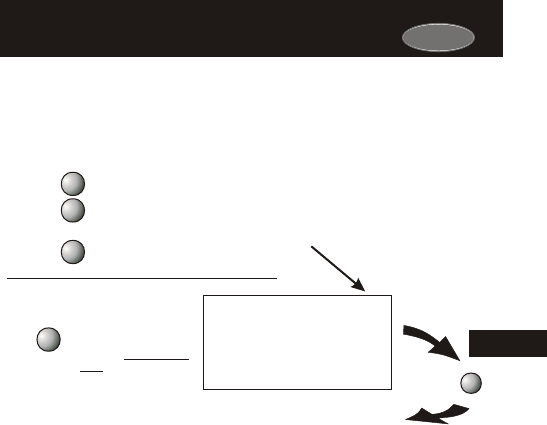
Page 12.2
Viewing the Heat Pump and
Reversing Valve Jumper Settings
Viewing the Heat Pump and
Reversing Valve Jumper Settings
Indicates that the
thermostat jumper
is set for an O
reversing valve
(energize in cooling)
or a b reversing valve
(energize in heating).
O
20
Setup
Press the PROGRAM button to leave the Setup screens. If no buttons are
pressed, the display will leave the setup screens after 30 seconds.
PROGRAM
Press
MODE
Press
PROGRAM
MODE
MODE
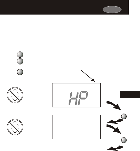
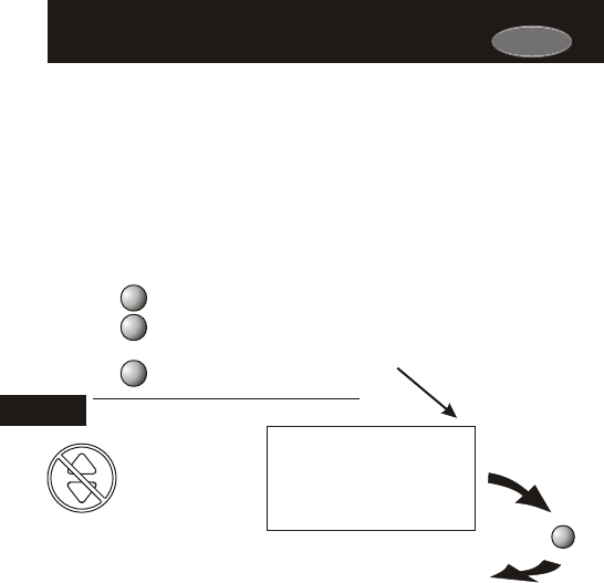
Steps 19 and 20 are ‘Read Only’ and may only be set with the
jumpers on the circuit board of the thermostat.
ON = Heat Pump
operation
OFF = Gas Electric
operation
I9
Setup
OFF
Press the MODE button. While holding
the MODE, press the PROGRAM
button to enter Setup screens.
Press the MODE button repeatedly
until this setup screen appears.
12
Note: Press the MODE
button momentarily
to move through the
setup screens. Press
and hold the MODE
button to move back-
wards through the
setup screens.
Carrier
Carrier
Page 12.3
Viewing the Electric Heat Jumper SettingViewing the Electric Heat Jumper Setting
Press the PROGRAM button to leave the Setup screens. If no buttons are
pressed, the display will leave the setup screens after 30 seconds.
PROGRAM
Press
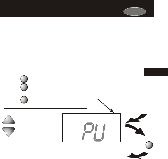
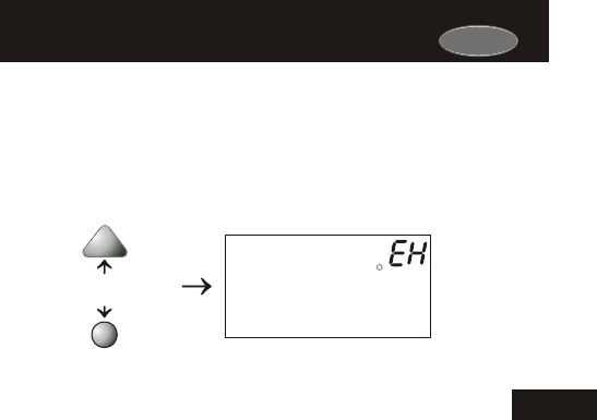
ON indicates that the
thermostat jumper is
set for Electric Heat
operation, or OFF for
Gas/Electric or Heat
Pump operation.
EH
2 i
OFF
Setup
PROGRAM
MODE
MODE
Placing the jumper on ELEC will cause the thermostat to turn on the
fan immediately any time there is a heat demand. Since most gas
furnaces control the fan, this feature should be off unless it is
necessary for the thermostat to energize the fan with first stage heat.
Step 21 is ‘Read Only’ and may only be set with the jumpers on the
circuit board of the thermostat.
Press the MODE button. While holding
the MODE, press the PROGRAM
button to enter Setup screens.
Press the MODE button repeatedly
until this setup screen appears.
12
Note: Press the MODE
button momentarily
to move through the
setup screens. Press
and hold the MODE
button to move back-
wards through the
setup screens.
Carrier
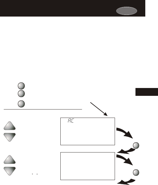
ENTER EMERGENCY HEAT: Only available if you have a Heat Pump
installed. To initiate the Emergency Heat feature, press the FAN
button. While holding the FAN button press UP button. The
Cool setpoint display will read ‘EH’ (emergency heat).
the
Press for
Emergency Heat
FAN
HEAT
73
74
Page 12.4
OPERATION: During Emergency Heat operation the
thermostat will turn on the fan and the 2nd stage of heat
when there is a demand for heat. Also during Emergency
Heat the 1st stage of heating or cooling will be unavailable.
EXIT EMERGENCY HEAT: Follow the same steps as entering
Emergency Heat by pressing the FAN and UP buttons. During
Emergency Heat, only OFF and HEAT modes are available by
pressing the MODE button.
Using Emergency HeatUsing Emergency Heat
12
I2:00
Su
Pm

Page 13.1
Section 13 Contents:
Adjusting the Heat/Cool
Differential..............................13.2
Adjusting the Cycles
Per Hour..................................13.3
Adjusting the Deadband..........13.4
Adjusting the Minutes of
Run-Time Before the
Next Stage...............................13.6
Selecting 2nd Stage Turn
Off Temperature.....................13.7
SECTION 13
Timers and DeadbandsTimers and Deadbands
13
Carrier
Carrier
Page 13.2
Adjusting the Heat/Cool DifferentialAdjusting the Heat/Cool Differential
Press the PROGRAM button to leave the Setup screens. If no buttons
are pressed, the display will leave the setup screens after 30 seconds.
PROGRAM
Press
Adjust the minimum
difference between
cooling & heating
setpoints.
(0 - 6 )
The Heat and Cool setpoints will not be allowed to come any closer to
each other than the value in this step. This minimum difference is
enforced during Auto-Changeover operation.
HEAT
COOL
2
Setup
22
PROGRAM
MODE
MODE
Press the MODE button. While holding
the MODE, press the PROGRAM
button to enter Setup screens.
Press the MODE button repeatedly
until this setup screen appears.
Note: Press the MODE
button momentarily
to move through the
setup screens. Press
and hold the MODE
button to move back-
wards through the
setup screens.
13
Note: To increase the spread between the heating and cooling
setpoints, press the MODE button until only the heat setpoint is
displayed. Adjust the desired setpoint. Wait two seconds after
adjusting the set point so the thermostat can accept the change.
Press the MODE button until only the cool setpoint is displayed.
Adjust the desired setpoint.
Press the
MODE button again to enter the Auto-Changeover mode where
both the heat and cool setpoints are displayed.
Wait two seconds after adjusting the
set point so the thermostat can accept the change.
Carrier
Page 13.3
Adjusting the Cycles Per HourAdjusting the Cycles Per Hour
Press the PROGRAM button to leave the Setup screens. If no buttons are
pressed, the display will leave the setup screens after 30 seconds.
PROGRAM
Press
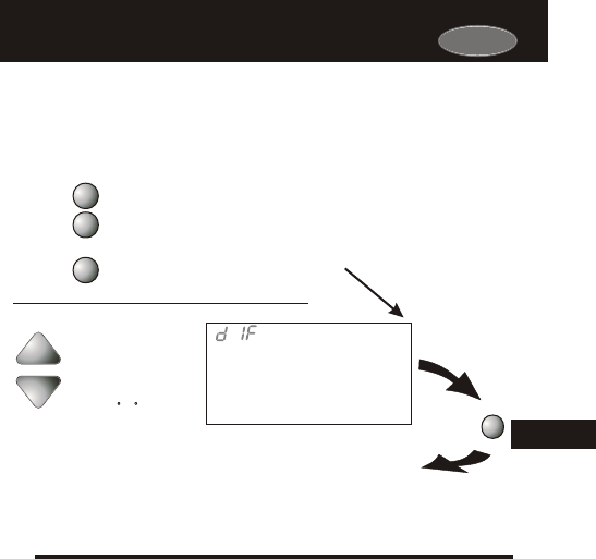
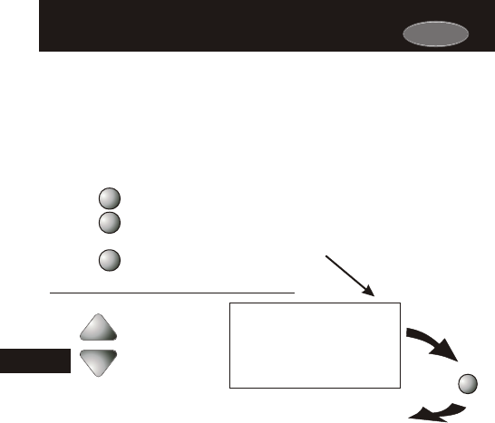
(d1, d, 2 - 6)
The Cycles Per Hour setting limits the number of times per hour
your HVAC unit may energize. For example, at a setting of 6 cycles
per hour the HVAC unit will only be allowed to energize once every 10
minutes. The Cycles Per Hour limit may be overridden and reset by
pressing the UP or DOWN buttons on the thermostat.
Cy
6
Setup
23
PROGRAM
MODE
MODE
Press the MODE button. While holding
the MODE, press the PROGRAM
button to enter Setup screens.
Press the MODE button repeatedly
until this setup screen appears.
Select the cycles per
hour limit.
d=cycles per hour
limit defeated.
d1=d + defeat 5 min.
compressor lockout.
Note: Press the MODE
button momentarily
to move through the
setup screens. Press
and hold the MODE
button to move back-
wards through the
setup screens.
13
Page 13.4
Adjusting the DeadbandAdjusting the Deadband
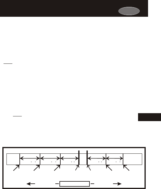
MULTI-STAGE OPERATION - Controls up to three Heat and two Cool
stages.
The 2nd Stage of heat or cool is
(A) The 1st Stage has been on for the time required (step #27,
page 13.6). It is adjustable from 0-60 minutes and the default
is two minutes.
(B) The temperature spread
than: the setpoint
turned on when:
from the setpoint is equal to or greater
plus the 1st stage deadband (step #24, next
page), plus the 2nd stage deadband (step #25, next page).
This 2nd stage deadband is adjustable from 0-10 degrees and
the default is two degrees.
The 3rd Stage of Heat is turned on when:
(A) The 2nd stage has been on for the time required (step #28,
page 13.6). It is adjustable from 0-60 minutes and the default
is two minutes.
(B) The temperature from the setpoint is equal to or greater
than: the setpoint plus the 1st stage deadband (step #24, next
page), plus the 2nd stage deadband (step #25, next page)
plus the 3rd stage deadband (step #26, next page). This 3rd
stage deadband is adjustable from 0-10 degrees and the
default is two degrees.
The above figure assumes the minimum on time for the prior stage has
been met to allow the next stage to turn on, once the deadbands have
been exceeded.
And
And
Heat
Setpoint
Cool
Setpoint
Deadband Deadband DeadbandDeadbandDeadband
db 1 db 1db 2 db 2db 3 (adj. 1-6 )(adj. 0-10 )(adj. 0-10 ) (adj. 0-10 )(adj. 1-6 )
1st Stage
turn on
2nd Stage
turn on
3rd Stage
turn on
1st Stage
turn on
2nd Stage
turn on
Heating Cooling
TEMPERATURE
DECREASE INCREASE
13
Carrier
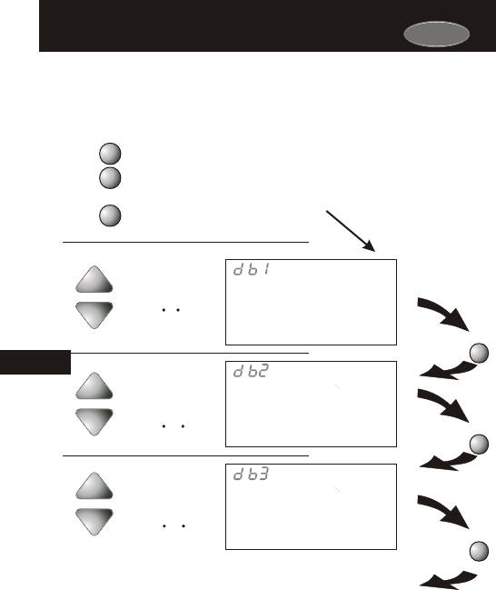
Page 13.5
Adjusting the DeadbandAdjusting the Deadband
Adjust the deadband
for the 1st stage.
(1 - 6 )
2
Setup
24
Adjust the deadband
for the 2nd stage.
(0 - 10 )
2
Setup
25
Adjust the deadband
for the 3rd stage.
(0 - 10 )
2
Setup
26
For more detailed information, please see the explanation on the
previous page.
Press the PROGRAM button to leave the Setup screens. If no buttons are
pressed, the display will leave the setup screens after 30 seconds.
PROGRAM
Press
MODE
Press
MODE
Press
PROGRAM
MODE
MODE
Press the MODE button. While holding
the MODE, press the PROGRAM
button to enter Setup screens.
Press the MODE button repeatedly
until this setup screen appears.
Note: Press the MODE
button momentarily
to move through the
setup screens. Press
and hold the MODE
button to move back-
wards through the
setup screens.
13
Carrier
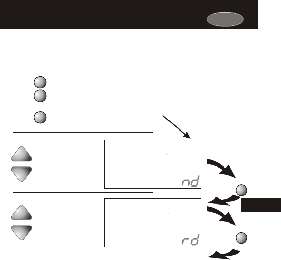
Page 13.6
Adjusting the Minutes of Run-Time
Before the Next Stage
Adjusting the Minutes of Run-Time
Before the Next Stage
(0 - 60 min.)
Adjust the amount of
time stage 2 must be
on before stage 3 turns
on.
0:02
3
Setup
28
(0 - 60 min.)
Adjust the amount of
time stage 1 must be
on before stage 2 turns
on.
0:02
2
Setup
27
For more detailed information, please see the explanation on page 13.4.
Press the PROGRAM button to leave the Setup screens. If no buttons are
pressed, the display will leave the setup screens after 30 seconds.
PROGRAM
Press
MODE
Press
PROGRAM
MODE
MODE
Press the MODE button. While holding
the MODE, press the PROGRAM
button to enter Setup screens.
Press the MODE button repeatedly
until this setup screen appears.
Note: Press the MODE
button momentarily
to move through the
setup screens. Press
and hold the MODE
button to move back-
wards through the
setup screens.
13
Carrier
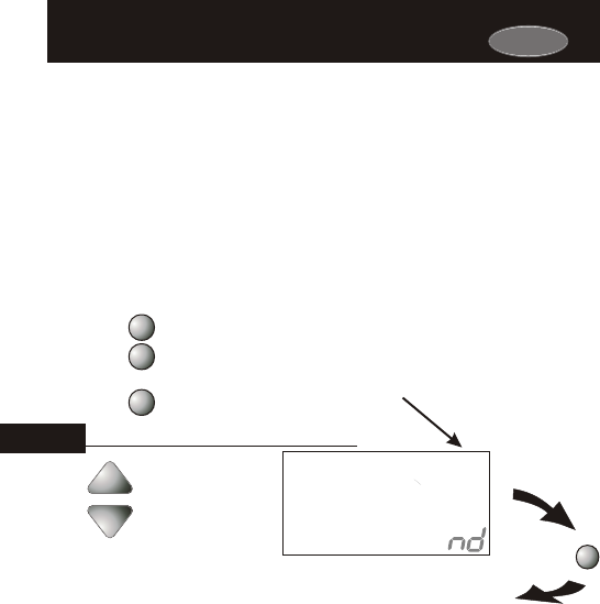
Page 13.7
Selecting 2nd Stage Turn
Off Temperature
Selecting 2nd Stage Turn
Off Temperature
If ON is selected, the second stage of cooling or heating will remain
energized until the thermostat reaches the setpoint on the thermostat
display.
If OFF is selected, the second stage of cooling or heating will turn off
after reaching the 1st stage (see page 13.4 for more
information).
deadband
Press the PROGRAM button to leave the Setup screens. If no buttons are
pressed, the display will leave the setup screens after 30 seconds.
PROGRAM
Press
Select On or Off:
On - 2nd stage will
remain on until
setpoint is reached.
Off - 2nd stage will
turn off after reaching
1st stage deadband.
On
Off
OFF
2
Setup
29
PROGRAM
MODE
MODE
Press the MODE button. While holding
the MODE, press the PROGRAM
button to enter Setup screens.
Press the MODE button repeatedly
until this setup screen appears.
Note: Press the MODE
button momentarily
to move through the
setup screens. Press
and hold the MODE
button to move back-
wards through the
setup screens.
13
Carrier

Page 14.1
Section 14 Contents:
Configuring a Thermostat Output
Jumper for Programmable
Output Operation...................14.2
Time-Based Control of the
Programmable Output...........14.3
Temperature-Based Control of
the Programmable Output.....14.6
SECTION 14
Using the Programmable OutputUsing the Programmable Output
14
Carrier
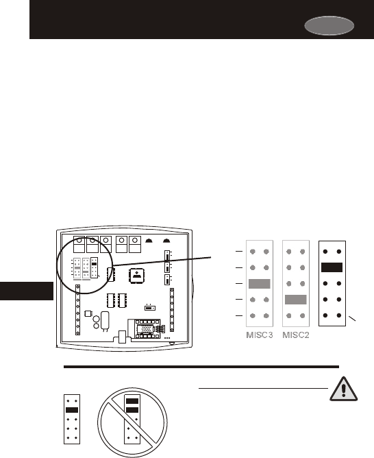
Carrier
ECON
Page 14.2
Setting a Thermostat Jumper for
Programmable Output Operation
Setting a Thermostat Jumper for
Programmable Output Operation
To control one of the MISC outputs using time, temperature, or
Internet/phone based operation, place the MISC1, or MISC2, or
MISC3 jumper on the terminal labeled PROG (see diagram below).
This extra output will supply 24VAC to the selected MISC terminal
based on the programming described in the following pages. Only
one of the three outputs (MISC1, MISC2, or MISC3) is required to
have this jumper.
For more information regarding the MISC1, MISC2,
and MISC3 outputs, please see section 21.
In the diagram below, the MISC1 jumper has
been set for PROG operation.
NEVER PUT MORE THAN ONE JUMPER
ON THE SAME MISC JUMPER BLOCK!
THIS MAY DAMAGE THE THERMOSTAT
AND VOID YOUR WARRANTY
MISC3 MISC3
OK
IMPORTANT CAUTION
DEHUM
W3
PROG
HUM
MISC3 MISC2 MISC1
Y2
(MISC1
ONLY)
14
HP
GAS
B
O
ELEC
GAS
(FAN)
W1
Y1
G
R
C
MISC2
W2
MISC1
Rs2
RSGND
MISC3
RS+5
Rs1
W3
HUM
DEHUM
MISC3 MISC2 MISC1
Y2
(MISC1
ONLY)
INSTALL HUMIDITY
MODULE WITH SENSING
ELEMENT OUTWARD
HUM
NO HUM
1
2
4
6
8
X
Z
1
5
7
9
Y
3
PROG
CK1
CKGND
ECON
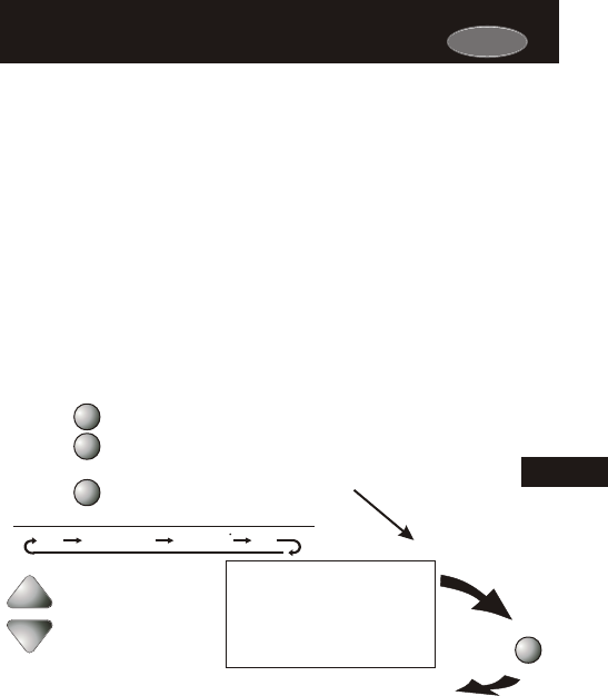
Carrier
Press the UP button to
set the programmable
output for time based
operation. The digits in the
clock area will appear.
Page 14.3
Time-Based Control of the
Programmable Output
Time-Based Control of the
Programmable Output
To operate one of the MISC outputs using time-based operation, set
Advanced Setup step #30 (below) for Time i8:88. This extra output
will supply 24VAC to the selected MISC terminal, which is especially
useful for devices that require a start and stop time. Refer to page
14.4 - 14.5 for more details on programming this output.
Possible TIME scenarios:
1) An exterior lighting system that needs to be energized every
day between the hours of 8pm and 1am.
2) A sprinkler system that needs to be energized every day
between the hours of 2am and 4am.
Continued on
the next page
Press
MODE
PROGRAM
MODE
MODE
Press the MODE button. While holding
the MODE, press the PROGRAM
button to enter Setup screens.
Press the MODE button repeatedly
until this setup screen appears.
Note: Press the MODE
button momentarily
to move through the
setup screens. Press
and hold the MODE
button to move back-
wards through the
setup screens.
OFF Time = Temp = Aux
I8:88
88
14
I8:88
Setup
30
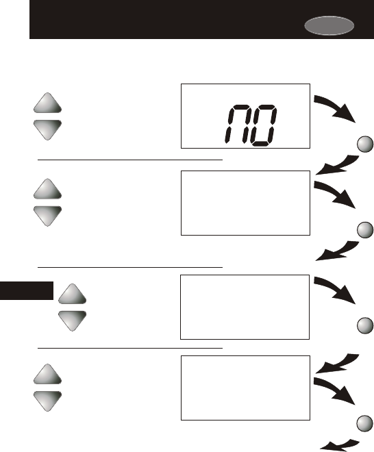
Carrier
Day
7
Setup
32
Setup
3 i
Page 14.4
Mo
Setup
33
Am
7:00
Mo
Start Setup
34
Press
MODE
Press
MODE
Press
MODE
Continued on
the next page
Press
MODE
If Step 32 is set for 1-Day, then Day of the
Week and Copy functions do not appear or apply.
7-Day
1-Day
Select 7-Day or 1-Day
Programming:
7-Day = Different program
for each day.
1-Day = Same program
every day.
Adjust the program-
mable output start time
for Monday.
(24 Hours)
Select the day of
the week
Time-Based Control of the
Programmable Output
Time-Based Control of the
Programmable Output
NC
NO
Programmable Output Polarity:
NC = Normally Closed to turn off
between the start and stop times
in steps 34 and 35.
NO = Normally Open to operate
between the start and stop times
in steps 34 and 35.
14
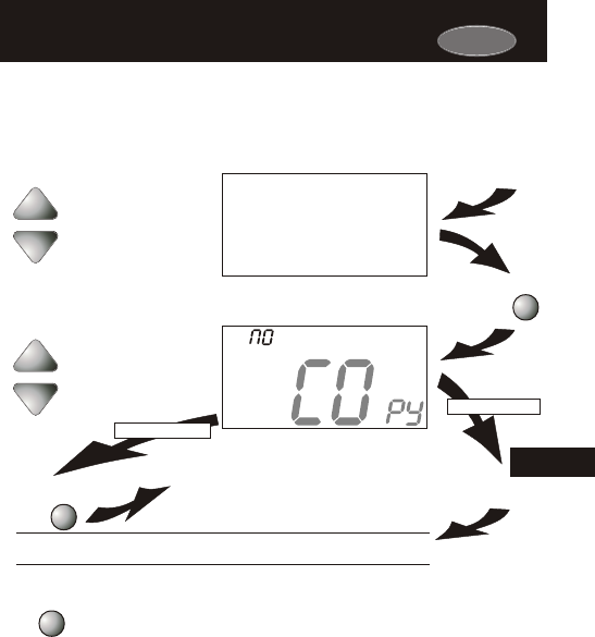
Page 14.5
Press
MODE
Adjust the programmable
output stop time for Monday
If Yes is selected:
If No is selected:
Press
MODE
Press
FAN
Yes
No
9:00
Mo
Setup
35
Pm
Tu
If Step 32 is set for 1-Day, then Day of the
Week and Copy functions do not appear or apply.
Select Yes to copy the
previous day’s program
to this day.
Selecting Yes, then pressing FAN will copy the
previous day’s program. If yes is selected each
time, this routine will repeat.
Once configuration of the programmable output has been
completed, press the MODE button to move on to the next
setup step, or press the PROGRAM button to exit Advanced
Setup.
Time-Based Control of the
Programmable Output
Time-Based Control of the
Programmable Output
If No is selected, as in previous steps, flashing prompts for input will appear for
the start and stop times for the next day.
Stop
14
Carrier
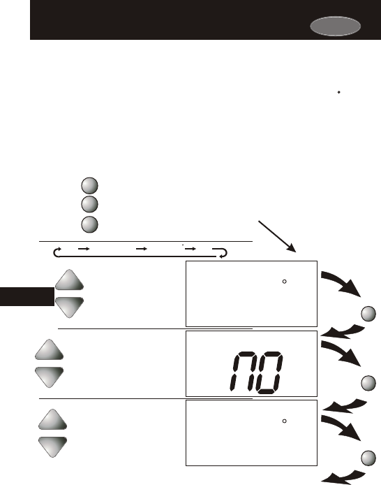
Carrier
Page 14.6
Temperature-Based Control of the
Programmable Output
Temperature-Based Control of the
Programmable Output
To operate a MISC output using temperature-based operation,
program advanced setup step #30 (below) for temperature 88 .
his extra output will supply 24VAC to the selected MISC terminal
based on the temperature of RS1 and the setpoint in step #36 (below).
T
Press the UP button twice
to set the programmable
output for temperature-
based operation. The
large temperature digits
will appear.
Possible TEMPERATURE scenario:
1) An exhaust fan in the attic of a store that needs to be energ-
ized when the attic temperature is above 85 degrees.
Press the PROGRAM button to leave the Setup screens. If no buttons are
pressed, the display will leave the setup screens after 30 seconds.
PROGRAM
Press
MODE
PROGRAM
MODE
MODE
Press the MODE button. While holding
the MODE, press the PROGRAM
button to enter Setup screens.
Press the MODE button repeatedly
until this setup screen appears.
Press
Adjust the programmable
output setpoint.
o
o
(35-125 )
Setup
30
88
80
Setup
36
Setup
3 i
NC
NO
Programmable Output Polarity:
NC = Normally Closed to operate
when the setpoint is less than
the setpoint in step #36.
NO = Normally Open to operate
when the setpoint is equal to or
greater than the setpoint in step
#36.
MODE
Press
Note: Press the MODE
button momentarily
to move through the
setup screens. Press
and hold the MODE
button to move back-
wards through the
setup screens.
OFF Time = Temp = Aux
I8:88
88
14
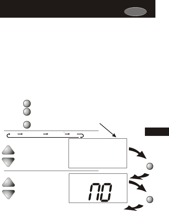
Possible REMOTE scenarios:
1) Arm the alarm system in your building after you have left for
the day.
3) Turn on your interior lights while you’re closed.
2) Turn off your sign lights after arriving home.
Page 14.7
Internet/Phone Control of the
Programmable Output
Internet/Phone Control of the
Programmable Output
To operate a MISC output using Internet/phone-based operation,
program advanced setup step #30 for Aux . (below) This terminal is
especially useful for devices that can be energized via the Internet.
Telephone control may also be available when the thermostat is
connected to the Internet.
Press the UP button three
times to set the
programmable output
for Aux (web-based
operation).
Press the PROGRAM button to leave the Setup screens. If no buttons are
pressed, the display will leave the setup screens after 30 seconds.
PROGRAM
Press
PROGRAM
MODE
MODE
Press the MODE button. While holding
the MODE, press the PROGRAM
button to enter Setup screens.
Press the MODE button repeatedly
until this setup screen appears.
Setup
3 i
NC
NO
Programmable Output Polarity:
NC = Normally Closed to operate
when programmed to be OFF
through the phone or internet.
NO = Normally Open to operate
when programmed to be ON
through the phone or internet.
MODE
Press
Note: Press the MODE
button momentarily
to move through the
setup screens. Press
and hold the MODE
button to move back-
wards through the
setup screens.
OFF Time = Temp = Aux
I8:88
88
14
AUX
Setup
30
Carrier

Carrier
Page 15.1
Section 15 Contents:
Installing the Remote
Sensors...................................15.2
Controlling or Reading the
Remote Temperature (RS1)...15.3
Averaging the Remote Sensor
(RS1) with the Thermostat
Sensor.....................................15.4
SECTION 15
Programming Remote Sensor OperationProgramming Remote Sensor Operation
15
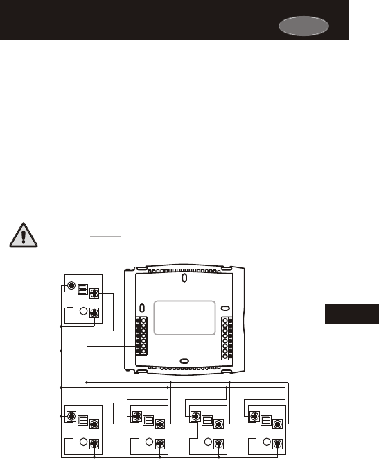
Carrier
Page 15.2
Installing the Remote SensorsInstalling the Remote Sensors
Up to eight wired or wireless remote sensors may be installed on the
thermostat (RS1) to control the temperature in other rooms. If more
than one sensor is connected to (RS1) the thermostat will average the
sensors to determine the displayed temperature reading. One wired or
wireless remote sensor may be installed to read the outside temp-
erature (RS2). If a sensor(s) is connected to RS1 and is programmed
to control the thermostat, the degree icon on the thermostat will blink
once per second to indicate that a remote sensor reading is being dis-
played. The wired sensor can be connected to the thermostat with up
to 150’ of 18 ga., 300’ of 20 ga., or 450’ of 22 ga. unshielded, therm-
ostat wire. If multiple sensors are wired to the thermostat, then the
total wiring distance of the furthest sensor should be used in determin-
ing the appropriate wire gauge. The wired sensor can be connected to
the thermostat using a two or three wire installation. If a two wire instal-
lation is required, then RS+5 must be connected to RSGND (see below).
This wire MUST be completely separated from the thermostat
or any other control wiring and must NOT be in the same
conduit as high voltage wiring.
15
See the Remote Sensor accessory for further details.
RS1-1
Y1
G
R
C
MISC2
CK1
CKGND
W1/O/B
MISC1
RS+5
RS1
RSGND
W2
RS2
MISC3
RS1-4RS1-3RS1-2
RS2
RS
RS-GND
RS+5
RS
RS-GND
RS+5
RS
RS-GND
RS+5
RS
RS-GND
RS+5
RS
RS-GND
RS+5
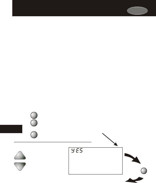
Carrier
Page 15.3
The thermostat may be programmed to only READ the remote sensor,
or to CONTROL to the remote sensor. Refer to advanced setup step
#37, below.
Controlling or Reading the
Remote Temperature (RS1)
Controlling or Reading the
Remote Temperature (RS )1
Press the PROGRAM button to leave the Setup screens. If no buttons are
pressed, the display will leave the setup screens after 30 seconds.
PROGRAM
Press
Optional Remote Sensor:
YES = Control to Remote
Sensor RS1.
NO = Read Only Remote
Sensor RS1.
YES
NO
PROGRAM
MODE
MODE
Press the MODE button. While holding
the MODE, press the PROGRAM
button to enter Setup screens.
Press the MODE button repeatedly
until this setup screen appears.
Note: Press the MODE
button momentarily
to move through the
setup screens. Press
and hold the MODE
button to move back-
wards through the
setup screens.
15
Remote
Setup
37
Control Sensor (RS1): If step #37 is set to CONTROL to the remote
sensor, the thermostat will ignore the reading of its internal
temperature sensor and only display the temperature reading from
the remote sensor. The degree icon on the thermostat will blink
once per second to indicate that a remote sensor reading is being
displayed.
Read Only Sensor (RS1): If step #37 is set to only READ to the
remote sensor, the thermostat will not use this sensor for temp-
erature control. This sensor may be viewed by entering advanced
setup (see below) and pressing and holding the MODE button to
scroll backwards one step to setup step #48 (see page 22.4).
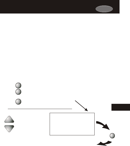
Carrier
Page 15.4
Averaging the Remote Sensor (RS1) with
the Thermostat Sensor
Averaging the Remote Sensor (RS1) with
the Thermostat Sensor
If step #37 is set to control to the remote sensor, the thermostat will
ignore the reading of its internal temperature sensor and only display
the temperature reading from the remote sensor. The degree icon on
the thermostat will blink once per second to indicate that a remote
sensor reading is being displayed.
If step #38 is set to ON (see below), the thermostat will average its
internal sensor with the wired temperature sensor connected to RS1.
I
The temperature displayed will be the
average of the thermostat’s internal sensor and the remote (RS1)
sensor(s).
f multiple remote temperature sensors are installed on RS1, they will
automatically average together.
Remote
Press the PROGRAM button to leave the Setup screens. If no buttons are
pressed, the display will leave the setup screens after 30 seconds.
PROGRAM
Press
Optional Remote Sensor
Operation:
ON = Averages thermostat
sensor with Remote
Sensor 1.
OFF = Does not average
thermostat sensor
with Remote Sensor 1.
On
Off
OFF
Setup
38
PROGRAM
MODE
MODE
Press the MODE button. While holding
the MODE, press the PROGRAM
button to enter Setup screens.
Press the MODE button repeatedly
until this setup screen appears.
Note: Press the MODE
button momentarily
to move through the
setup screens. Press
and hold the MODE
button to move back-
wards through the
setup screens.
15

Page 16.1
Section 16 Contents:
Dry Contact Operation............ 16.2
Dry Contact Polarity.................16.2
Dry Contact Programming.......16.3
Random Start Operation..........16.4
SECTION 16
Programming the Dry ContactProgramming the Dry Contact
16
Carrier
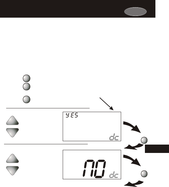
Carrier
Page 16.2
Dry Contact Operation Dry Contact Operation
YES
NO
Press the PROGRAM button to leave the Setup screens. If no buttons are
pressed, the display will leave the setup screens after 30 seconds.
PROGRAM
Press
40
Setup
NC
NO
MODE
Press
PROGRAM
MODE
MODE
Press the MODE button. While holding
the MODE, press the PROGRAM
button to enter Setup screens.
Press the MODE button repeatedly
until this setup screen appears.
If the dry contact is going to be used, select YES in step #39. If the
dry contact is not going to be used, select NO in step #39 below.
DRY CONTACT POLARITY - The terminals may be set to be
Normally Open (NO) or Normally Closed (NC) in step #40.
If NO is selected the dry contact will operate when it is forced
closed. If NC is selected, the dry contact will operate until it is
forced open.
Set to YES if the dry
contact will be used.
Set to NO if the dry
contact will not be used.
Dry Contact Polarity:
Normally Closed (NC)
Normally Open (NO)
Note: Press the MODE
button momentarily
to move through the
setup screens. Press
and hold the MODE
button to move back-
wards through the
setup screens.
16
Setup
39
Step 40 appears only if step 39 is “YES”.
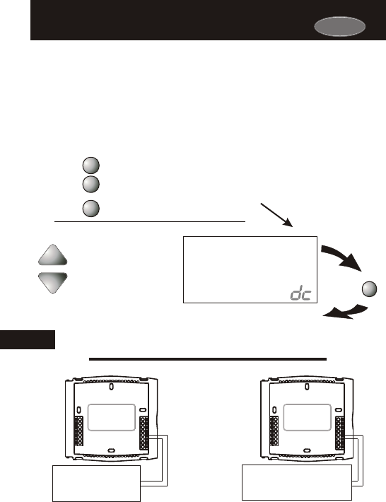
Carrier
Page 16.3
Dry Contact ProgrammingDry Contact Programming
OCCUPIED 1 OR SERVICE THE CONDENSATE DRAIN PAN - If
Occupied 1 is selected in step #41 (below), when the dry contact is
energized the thermostat will be forced into Occupied 1 setpoints
and the Occupied 1 icon will blink (Section 6). The thermostat must
be in Program On mode for this feature to have any effect.
If Service Pan is selected, when the dry contact is energized the
thermostat will lockout Y1 (compressor) and write Service Pan on
the display.
Press the PROGRAM button to leave the Setup screens. If no buttons are
pressed, the display will leave the setup screens after 30 seconds.
PROGRAM
Press
Select Service Pan to lockout
Y1 when the dry contact is
energized. Select Occupied 1
to enable Occupied 1 setpoints
when the dry contact is
energized.
Service Pan
Occupied 1
Setup
4 i
occupied
1
Connect wires to a time
clock or other device to
force the thermostat into
Occupied 1.
Y1
G
R
C
MISC2
CK1
CKGND
W1/O/B
MISC1
RS+5
RS1
RSGND
W2
RS2
MISC3
Y1
G
R
C
MISC2
CK1
CKGND
W1/O/B
MISC1
RS+5
RS1
RSGND
W2
RS2
MISC3
OR
Occupied 1 Service Pan
PROGRAM
MODE
MODE
Press the MODE button. While holding
the MODE, press the PROGRAM
button to enter Setup screens.
Press the MODE button repeatedly
until this setup screen appears.
Note: Press the MODE
button momentarily
to move through the
setup screens. Press
and hold the MODE
button to move back-
wards through the
setup screens.
16
Connect wires to a device that
will complete the circuit betw-
een CK1 and CKGND when the
Condensate Drain Pan is full.
NOTE: If Service Pan is selected and the dry contact was closed at least once, the
Service Pan icon will remain on the display to alert the user that a problem has
occurred. This icon will be cleared once a button is pressed.
Step 41 appears only if step 39 is “YES”.

Carrier
Page 16.4
Random Start OperationRandom Start Operation
This feature allows a 2 to 30 second delay before energizing
the thermostat outputs after any of these events:
16
Loss of Power to the thermostat: When power to the thermostat
is interrupted and then restored, Random Start will lockout the
outputs of the thermostat for a random amount of time. This
delay helps to keep multiple thermostats from energizing their
outputs at the same time after a power outage.
Changing from an Unoccupied time period to an Occupied
time period: If the thermostat is running in the Program On mode
and the start time for an Occupied period forces the thermostat
from Unoccupied to Occupied 1, Random Start will lockout all
outputs of the thermostat for a random amount of time. This
delay helps to keep multiple thermostats from energizing their
outputs at the same time each day.
Closure of the Dry Contact to force Occupied 1 time period:
If step #41 (previous page) is programmed for Occupied 1, then
Random Start will lockout all outputs of the thermostat for a
random amount of time when a Dry Contact closure occurs
(depending on step #40). This delay helps to keep multiple
thermostats from energizing their outputs each time the Dry
Contact is used.
Sensing of a light source by the Light Sensor to force
Occupied 1 time period:
If step #42 (page 17.2) is programmed YES for Light Activated
operation, Random Start will lockout the outputs of the thermostat
for a random amount of time when a light source forces the
thermostat into Occupied 1. This delay helps to keep multiple
thermostats from energizing their outputs each time the lights are
turned on.

Page 17.1
Section 17 Contents:
Setting up the Thermostat
for Light Activated
Operation................................17.2
Adjusting the Light Sensor.....17.3
SECTION 17
Light Activated OperationLight Activated Operation
17
Carrier
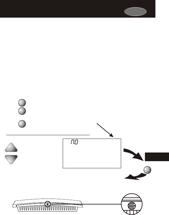
33CS450-01
Carrier
Select YES if the
thermostat should be
Light Activated.
Select NO to allow only
Time Period Programming
(Section 6).
Press the PROGRAM button to leave the Setup screens. If no buttons are
pressed, the display will leave the setup screens after 30 seconds.
PROGRAM
Press
A light sensor is provided on the thermostat for light activation. If the
thermostat is set up to be light activated, the thermostat will enter
Occupied 1 and blink the Occupied 1 icon when a light source is
detected. When the thermostat is set up to be light activated, the time
period programming for each day should be set to OFF (Section 6).
The thermostat must be in Program On mode for light activation to
have any effect. Page 17.3 explains how to adjust the light sensitivity
for this type of operation.
Page 17.2
Setting up the Thermostat for
Light Activated Operation
Setting up the Thermostat for
Light Activated Operation
42
Setup
Light Sensor
The Light Sensor is located on
the top of the thermostat.
NOTE: Light activation does not work in Holiday mode (Section 21).
17
PROGRAM
MODE
MODE
Press the MODE button. While holding
the MODE, press the PROGRAM
button to enter Setup screens.
Press the MODE button repeatedly
until this setup screen appears.
Note: Press the MODE
button momentarily
to move through the
setup screens. Press
and hold the MODE
button to move back-
wards through the
setup screens.
YES
NO
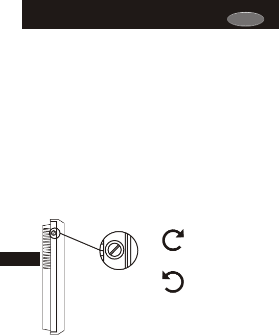
Page 17.3
Adjusting the Light Sensor Adjusting the Light Sensor
The light sensor can be adjusted for variable degrees of sensitivity.
The sensitivity adjustment screw is located on the side of the
thermostat, as illustrated below. Turning the screw clockwise
increases the sensitivity of the sensor to light.
The Light Sensor Adjustment Screw
is located on the side of the thermostat.
Light Sensor
Adjustment Screw
Turn the screw clockwise
to INCREASE light sensor
sensitivity
Turn the screw counter-
clockwise to DECREASE
light sensor sensitivity
Due to varying lighting conditions, light activation may
not be suitable for all installations.
To check for correct sensitivity, place the thermostat in the Program On
mode. When the lights are on the thermostat should enter Occupied 1
and blink the Occupied 1 icon. If the thermostat does not enter
Occupied 1 while the lights are on, use the supplied screw driver to
turn the light sensor screw clockwise until the Occupied 1 icon appears
on the display. The thermostat should enter an unoccupied period
when the lights are off. If the sensor does not enter an unoccupied
period when the lights are turned off, use the supplied screw driver to
turn the light sensor screw counterclockwise until the Unoccupied icon
appears on the display, with the lights off.
17
Carrier
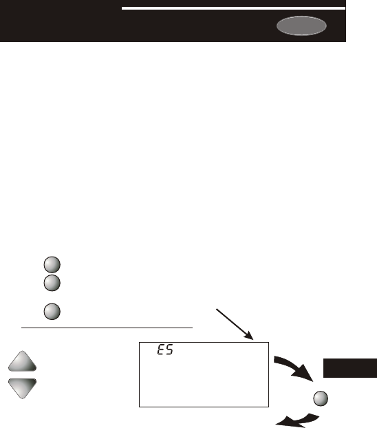
SECTION 18
Energy Save OperationEnergy Save Operation
Carrier
Page 18.1
How to Use the Energy Save FeatureHow to Use the Energy Save Feature
If the thermostat is configured to be programmable (Section 4), and
Energy Save has been selected in step #43 (below), the room will
attempt to reach the selected comfort temperature at the exact time
programmed into the thermostat. Energy Save, or more commonly
known as Smart Recovery, only works when the thermostat enters
Occupied 1 from Unoccupied. For example, if the Unoccupied
program is set for 6pm at 55°F heating and 85°F cooling, and the
Occupied 1 program is set for 8am at 72°F heating and 75°F cooling,
the thermostat will turn the system on before 8am in an effort to bring
the temperature to its correct setting at exactly 8am.
The P374-2900 learns from experience, so please allow 4-8 days
after a program change or after initial installation to give Energy Save
time to adjust to local weather, the construction of your business, and
your heating and cooling system.
Press the PROGRAM button to leave the Setup screens. If no buttons are
pressed, the display will leave the setup screens after 30 seconds.
PROGRAM
Press
Select Energy Save
on or off.
On
Off
43
Setup
PROGRAM
MODE
MODE
Press the MODE button. While holding
the MODE, press the PROGRAM
button to enter Setup screens.
Press the MODE button repeatedly
until this setup screen appears.
OFF
Note: Press the MODE
button momentarily
to move through the
setup screens. Press
and hold the MODE
button to move back-
wards through the
setup screens.
18

Page 19.1
Section 19 Contents:
Setting and Resetting the
Service Filter (Fan Run-Time)
Alerts........................................19.2
Setting and Resetting the UV
Light Run-Time Alerts.............19.3
Setting and Resetting the
Humidify Run-Time Alerts......19.4
SECTION 19
Programming Run-Time AlertsProgramming Run-Time Alerts
19
Carrier
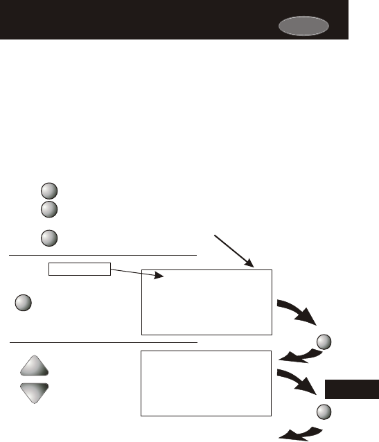
Carrier
19
Page 19.2
How to Set and Reset the Service Filter
(Fan Run-Time) Alert
How to Set and Reset the Service Filter
(Fan Run-Time) Alert
This counter keeps track of the number of hours of fan run-time
whether the fan is energized in the Heating or Cooling modes, or in
stand alone fan operation. The Service Filter icon will appear after the
preset number of hours of fan run-time in step #45 (below) has been
achieved. Setting this counter to zero in step #45 will prevent the
Service Filter icon from ever appearing.
PROGRAM
MODE
MODE
Press the MODE button. While holding
the MODE, press the PROGRAM
button to enter Setup screens.
Press the MODE button repeatedly
until this setup screen appears.
Press the PROGRAM button to leave the Setup screens. If no buttons are
pressed, the display will leave the setup screens after 30 seconds.
PROGRAM
Press
Reset the counter to 0 to
remove the Service Filter
icon from the display.
Press
FAN
(0 - 1950 hours)
0
Service Filter
Setup
44
0
Service Filter
Setup
45
MODE
Press
Hours the fan has
run since last reset
Adjust the number of
hours, in increments of
50, the fan will run
before the Service
Filter icon appears on
the display. 0 = off.
Note: Press the MODE
button momentarily
to move through the
setup screens. Press
and hold the MODE
button to move back-
wards through the
setup screens.
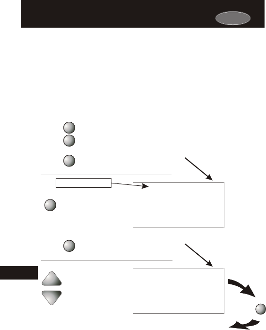
Carrier
Page 19.3
How to Set and Reset the UV Light
Run-Time Alert
How to Set and Reset the UV Light
Run-Time Alert
This counter keeps track of the number of days since the UV Light
counter has been reset. The UV Light icon will appear after the
number of days has been achieved, as shown in step #46 (below).
Setting the counter to zero in Step #46 will prevent the Service UV
Light icon from ever appearing.
Press the PROGRAM button to leave the Setup screens. If no buttons are
pressed, the display will leave the setup screens after 30 seconds.
PROGRAM
Press
(0 - 1990 days)
0
UV Light
Setup
46
Service
PROGRAM
MODE
MODE
Reset the counter to 0 to
remove the Service UV
Light icon from the display.
Press
FAN
0
UV Light
Setup
I8
Service
Days since the UV Light
icon has been reset
Press the MODE button. While holding
the MODE, press the PROGRAM
button to enter Setup screens.
Press the MODE button repeatedly
until this setup screen appears.
Adjust the number of days
in increments of 10 before
the UV Light icon appears
on the display. 0 = off.
19
Note: Press the MODE
button momentarily
to move through the
setup screens. Press
and hold the MODE
button to move back-
wards through the
setup screens.
MODE
Press the MODE button repeatedly
until this setup screen appears.
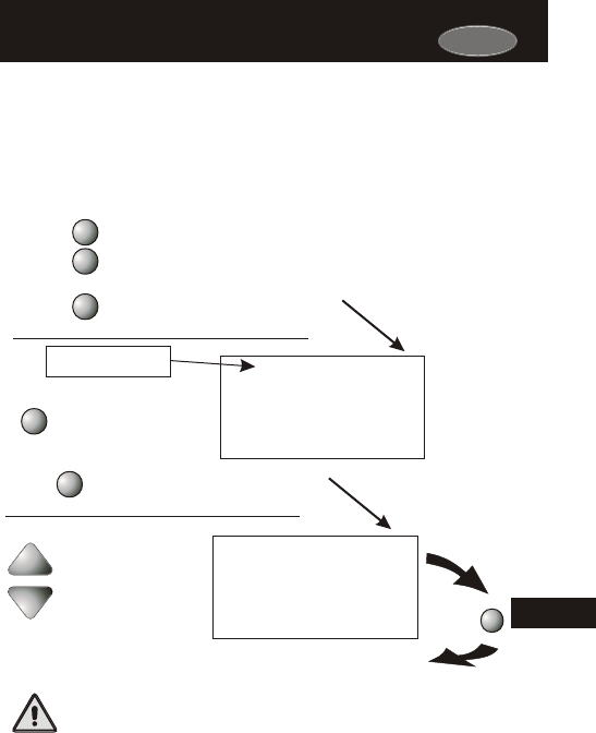
Carrier
Page 19.4
How to Set and Reset the Humidifier
Run-Time Alert
How to Set and Reset the Humidifier
Run-Time Alert
This counter keeps track of the number of days since the Service
Humidify icon was last reset; this icon will appear after the number of
days set in step #47 (below) has elapsed. Setting this counter to zero
in step #47 will prevent the Service Humidify icon from ever appearing.
Press the PROGRAM button to leave the Setup screens. If no buttons are
pressed, the display will leave the setup screens after 30 seconds.
PROGRAM
Press
Press
FAN
0
Service
Setup
I7
Humidify
0
Setup
47
Service Humidify
PROGRAM
MODE
MODE
Press the MODE button. While holding
the MODE, press the PROGRAM
button to enter Setup screens.
Press the MODE button repeatedly
until this setup screen appears.
Reset the counter to 0 to
remove the Service Humidify
icon from the display.
Adjust the number of days
in increments of 10 before
the Service Humidify icon
appears.
0 = Off
(0 - 1990 days)
Days since the last reset
of the Service Humidify
counter.
The humidifier run-time alert does not take the place of
any humidifier manufacturer’s recommended maintenance
plan; it only serves as a helpful reminder.
MODE
Press the MODE button repeatedly
until this setup screen appears.
19
Note: Press the MODE
button momentarily
to move through the
setup screens. Press
and hold the MODE
button to move back-
wards through the
setup screens.
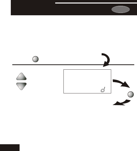
Carrier
Page 20.1
When the thermostat is programmed for a Holiday mode, it will take
effect at 12:00 am of the next day. In order for the Holiday mode to
take effect the thermostat must be in the Program On mode.
The thermostat will control to the Unoccupied cooling and heating
setpoints set in Section 6, pages 6.2 and 6.3.
Holiday setpoints will be enforced for the number of days specified in
step #1 (0 - 99 days).
Select the number of days
that the Holiday schedule
will be in effect. A value
of 0 disables Holiday
mode.
y
I
Setup
0
Press
Press the HOLIDAY button to enter
the Holiday programming setup
steps.
HOLIDAY
Press
HOLIDAY
Press the HOLIDAY button to exit the setup screens. If no buttons are
pressed, the display will leave the setup screens after 30 seconds.
You cannot set the Heat setpoint any higher than the Cool setpoint minus
the deadband setting in Advanced Setup step #22 on page 13.2.
20
SECTION 20
Programming Holiday ModeProgramming Holiday Mode
(0 - 99 days)
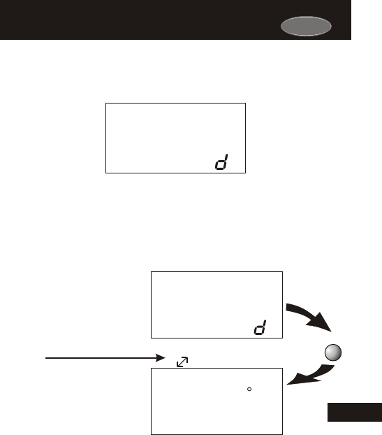
Carrier
Page 20.2
HOLIDAY DISPLAY - When the thermostat is placed into the
Holiday mode, the thermostat will display the screen shown below.
y
2
Programming Holiday Mode (continued)Programming Holiday Mode (continued)
To return the thermostat to normal operation from Holiday mode, press
the HOLIDAY button and adjust the number of days in step #1 to zero
(see previous page).
20
Override
occupied
30
Pm
HEAT
COOL
Program On
65
72
74
7:56
:
We
1
y
2
Press
OVERRIDE
Overriding the Holiday ModeOverriding the Holiday Mode
Pressing the OVERRIDE
button during Holiday Mode
will temporarily force the
thermostat into Occupied 1
comfort settings for 30 min.
The remaining Override time
will alternate with the clock
display.
The Override timer can be
set up to a maximum of four
(4:00) hours, in increments
of 30 minutes. If the timer
has been set for the max-
imum time, the next press of
the OVERRIDE button will
reset the timer, returning the
thermostat to the correct time
period program for the day.
Press the HOLIDAY button to return to normal operation.

Page 21.1
Section 21 Contents:
Configuring the Jumpers........21.2
Explanation of Jumper
Settings..................................21.3
SECTION 21
Configuring the MISC OutputsConfiguring the MISC Outputs
21
Carrier
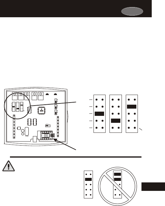
Configuring the JumpersConfiguring the Jumpers
ECON
Page 21.2
For additional flexibility, your thermostat has three configurable
outputs. These outputs are designed to have different functions
depending on how the jumpers are set (below).
Each output, labeled MISC1, MISC2, and MISC3 may be set for one
of the five choices available.
In the diagram below, the MISC3 jumper has been set for HUM*
(humidification) operation, the MISC2 jumper has been set for
DEHUM* (dehumidification) operation, and the MISC1 jumper has
been set for PROG (programmable) operation.
NEVER PUT MORE THAN
ONE JUMPER ON THE SAME
MISC JUMPER BLOCK!
DOING SO MAY DAMAGE
YOUR THERMOSTAT.
MISC3 MISC3
OK
W3
PROG
HUM
DEHUM
MISC3 MISC2 MISC1
Y2
(MISC1
ONLY)
CAUTION
21
HP
GAS
B
O
ELEC
GAS
(FAN)
W1
Y1
G
R
C
MISC2
W2
MISC1
RS2
RSGND
MISC3
RS+5
Rs1
W3
HUM
DEHUM
MISC3 MISC2 MISC1
Y2
(MISC1
ONLY)
INSTALL HUMIDITY
MODULE WITH SENSING
ELEMENT OUTWARD
HUM
NO HUM
1
2
4
6
8
X
Z
1
5
7
9
Y
3
PROG
CK1
CKGND
ECON
*The Humidity Module (sold separately) must
be installed to operate a humidification
and/or dehumidification system.
Carrier
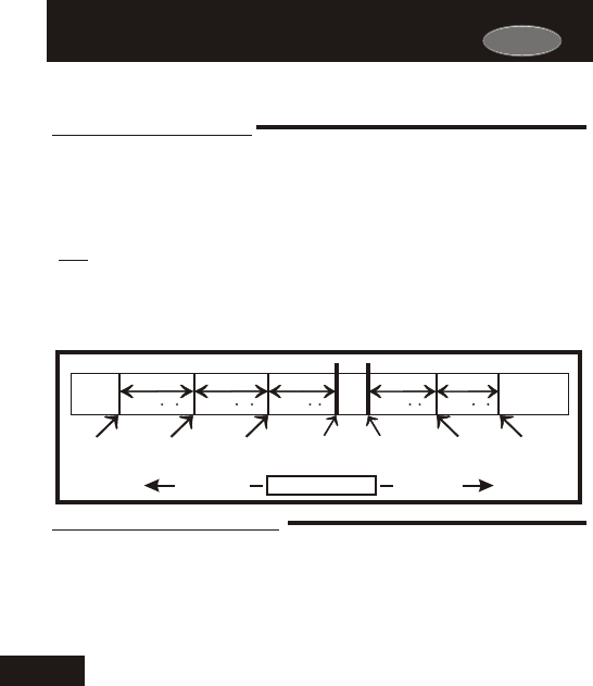
Carrier
PROG JUMPER SETTING
If the jumper for MISC1, MISC2, or MISC3 is set to PROG, the corresponding MISC screw
terminal on the backplate will control a pilot relay or other accessory.
Page 21.3
The 3rd Stage of Heat is turned on when:
(A) The 1st and 2nd stages have been on for the time required (steps 27
and 28, page 13.6). It is adjustable from 0-60 minutes and the default
is two minutes.
(B) The temperature from the setpoint is equal to or greater than: the set-
point plus the 1st stage deadband (step #24, 13.5), plus the 2nd stage
deadband (step #25, 13.5) plus the 3rd stage deadband (step #26,
13.5). This 3rd stage deadband is adjustable from 0-10 degrees and
the default is two degrees.
W3 JUMPER SETTING
If the jumper for MISC1, MISC2, or MISC3 is set to W3, the corresponding MISC screw terminal
on the backplate will control a third stage of heat.
Explanation of Jumper SettingsExplanation of Jumper Settings
And
Heat
Setpoint
Cool
Setpoint
Deadband Deadband DeadbandDeadbandDeadband
db 1 db 1db 2 db 2db 3 (adj. 1-6 )(adj. 0-10 )(adj. 0-10 ) (adj. 0-10 )(adj. 1-6 )
1st Stage
turn on
2nd Stage
turn on
3rd Stage
turn on
1st Stage
turn on
2nd Stage
turn on
Heating
Cooling
TEMPERATURE
DECREASE INCREASE
W3 MULTI-STAGE OPERATION EXPLAINED - PAGE 13.4
This jumper setting allows the MISC outputs to control a pilot relay by time,
temperature, or a signal from the Internet/Phone. The following are three
possible scenarios:
By Time: A device that requires a start and stop time. For example,
an exterior lighting system that needed to be energized every day
between the hours of 8pm and 1am.
By Temperature: An exhaust fan that needs to energize whenever
the temperature from RS1 rises above 90 degrees F.
By Remote: Remotely arming a security system through the web or phone.
PROGRAMMABLE OUTPUT - SECTION 14
21

Carrier
HUMIDIFICATION OPERATION - SECTION 9
If your HVAC unit is equipped with a humidification system and the Humidity
Module (sold separately) has been installed, the thermostat will provide power
to the MISC1, MISC2, or MISC3 terminal of the thermostat when the humidity in
the home falls below the humidity setpoint you have chosen. The value for this
setpoint ranges from 0% to 60%. If no humidity is desired or if a humidification
system has not been installed, set the value to 0%.
Page 21.4
DEHUM JUMPER SETTING
HUM JUMPER SETTING
If the jumper for MISC1, MISC2, or MISC3 is set to HUM, the corresponding MISC screw
terminal on the backplate will control a humidification system.
Explanation of Jumper Settings (continued)Explanation of Jumper Settings (continued)
If the jumper for MISC1, MISC2, or MISC3 is set to DEHUM, the corresponding MISC screw
terminal on the backplate will be connected to the dehumidification terminal of a furnace board.
NOTE: Not all furnaces have a dehumidification terminal.
DEHUMIDIFICATION OPERATION - SECTION 10
If your HVAC unit is equipped with a dehumidification system the thermostat will
operate in one of two ways.
1) Normally Closed (NC): The thermostat will de-energize the MISC1, MISC2,
or MISC3 terminal of the thermostat (this MISC terminal is connected to the
DEHUM terminal on your furnace) to allow the fan to run in low speed when
the humidity in the building is above the dehumidify setpoint you have
chosen and there is a call for 1st stage cooling.
2) Normally Open (NO):
The thermostat will energize the MISC1, MISC2, or
MISC3 terminal of the thermostat (this MISC terminal is connected to the
DEHUM terminal on your furnace) to allow the fan to run in low speed when
the humidity in the building is above the dehumidify setpoint you have
chosen and there is a call for 1st stage cooling. 21
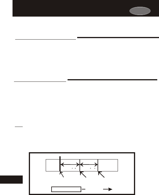
Carrier
ECON JUMPER SETTING
If the jumper for MISC2 or MISC3 is set to ECON, the corresponding MISC screw
terminal on the backplate will be connected to an economizer.
ECONOMIZER OPERATION - If your HVAC unit is equipped with an
economizer system, the thermostat will provide power to the MISC2 or
MISC3 terminal of the thermostat when the thermostat is in an occupied
time period. The MISC2 or MISC3 terminal will be de-energized when the
thermostat is in an unoccupied time period.
Y2 JUMPER SETTING
If the jumper for MISC1 is set to Y2 the MISC1 screw terminal on the backplate will control a
second stage of cooling.
Y2 OPERATION - SECTION 13
Control up to two Cool stages.
The 2nd Stage of cool is turned on when:
(A) The 1st Stage has been on for the time required (step #27,
page 13.6). It is adjustable from 0-60 minutes and the default
is two minutes.
(B) The temperature spread from the setpoint is equal to or greater
than: the setpoint plus the deadband (step #24, page 13.5), plus
the 2nd deadband (step #25, page 13.5). This 2nd deadband is
adjustable from 0-10 degrees and the default is two degrees.
Page 21.5
Explanation of Jumper Settings (continued)Explanation of Jumper Settings (continued)
And
21 Cool
Setpoint
DeadbandDeadband
db 1 db 2
(adj. 0-10 )(adj. 1-6 )
1st Stage
turn on
2nd Stage
turn on
Cooling
TEMPERATURE INCREASE

Page 22.1
Section 22 Contents:
Resetting the Thermostat to the
Factory Default Settings........22.2
Calibrating the Temperature
and Humidity Sensors...........22.3
Viewing the Remote
Temperature Sensors............22.4
SECTION 22
Factory Defaults, Calibration, and SensorsFactory Defaults, Calibration, and Sensors
22
Carrier
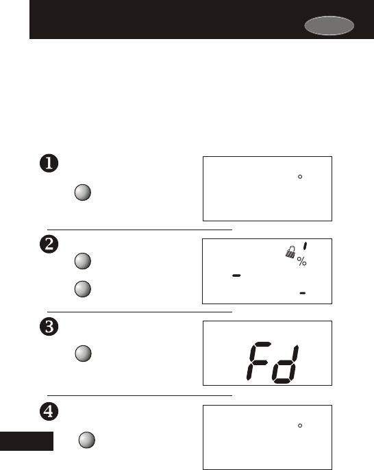
Carrier
AUTO
OFFON
Override
123
Unoccupied
Am
I8:88
SuMoTuWeThFrSa
Pm
AUXHEAT
COOL
FanOn
Service Filter
Pan UV Light
Program On
StartStop
DeHumidify
I88
Setup
Outside
Remote
88
L O
HI
88
If, for any reason, you desire to return all the stored settings back to
the factory default settings, follow the instructions below.
Page 22.2
Resetting the Thermostat to the
Factory Default Settings (for default values see page 24.1)
Resetting the Thermostat to the
Factory Default Settings (for default values see page 24.1)
WARNING: This will reset all Time Period and Advanced
Programming to the default settings. Any information entered
prior to this reset may be permanently lost.
Place the thermostat in the
OFF mode.
Press and hold the MODE
button. While holding the
MODE button, press and hold
the FAN button for 5 seconds.
All icons will appear on the
display.
After all of the icons appear,
release the MODE and FAN
buttons. Then press and hold
the FAN button for 5 seconds.
After the letters Fd appear on
the display (Factory Default),
release the FAN button. Press
the MODE button once to
return to normal operation.
OFF
OFF
I2:00
I2:00
72
Pm
Pm
FAN
FAN
72
MODE
MODE
MODE
Su
22
Su
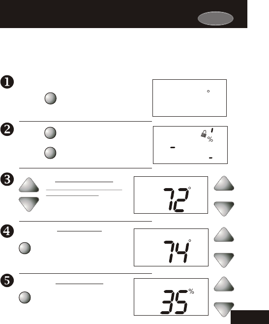
Carrier
After calibration is complete, press the MODE button once to save your
changes and return to normal operation.
AUTO
OFFON
Override
Unoccupied
Am
I8:88
SuMoTuWeThFrSa
Pm
AUXHEAT
COOL
FanOn
Service Filter
Pan UV Light
Program On
StartStop
DeHumidify
I88
Setup
Outside
Remote
88
L O
HI
88
123
Page 22.3
Calibrating the Temperature and Humidity SensorsCalibrating the Temperature and Humidity Sensors
OFF
I2:00
72
Pm
CALIBRATE
PRESS
TWICE
MODE
FAN
MODE
MODE Press and hold the MODE
button. While holding the
MODE button, press and hold
the FAN button for 5 seconds.
All icons will appear on the
display.
Under normal circumstances it will not be necessary to adjust the
calibration of the temperature and humidity sensors. If calibration is
required, please contact a trained HVAC technician to correctly
perform the following procedure.
Place the thermostat in the
OFF mode.
Press the UP and DOWN buttons
at the same time twice. The
thermostat temperature will be
displayed and may be calibrated
using the UP or DOWN buttons.
Press the MODE button once. The
relative humidity at the thermostat will be
displayed and may be calibrated using the
UP or DOWN buttons.
CALIBRATE
CALIBRATE
MODE
Press the MODE button once. The
remote sensor temperature will be
displayed and may be calibrated using the
UP or DOWN buttons. If a remote sensor
is not installed, a temperature reading
-127 degrees will appear.
THERMOSTAT SENSOR
REMOTE SENSOR
HUMIDITY SENSOR
Su
22
Remote
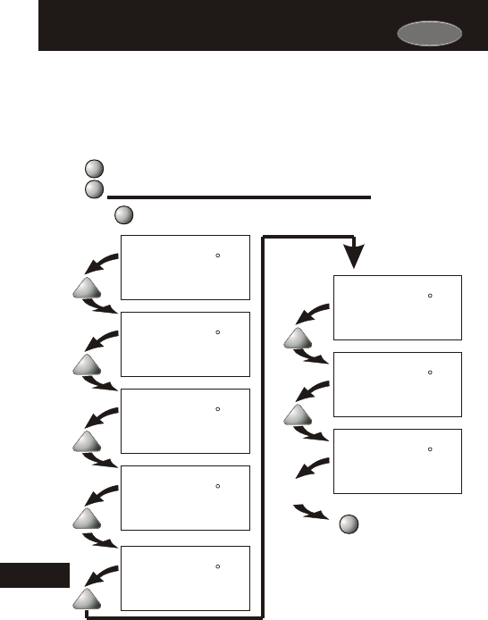
Page 22.4
Viewing the Remote Temperature SensorsViewing the Remote Temperature Sensors
Each sensor is programmed with a “hard-coded” address that the
thermostat “scans” in order from lowest to highest. Therefore, in
order to determine which sensor corresponds to the number on the
setup screen you will need to disconnect each sensor from the group
in order to determine which sensor number reads dashes.
i
Remote
Remote
Sensor #1.
2
Remote
Remote
Sensor #2
3
Remote
Remote
Sensor #3
4
Remote
Remote
Sensor #4
6
Remote
Remote
Sensor #6
7
Remote
Remote
Sensor #7
Press the MODE button to
return to normal operation.
PROGRAM
5
Remote
Remote
Sensor #5
8
Remote
Sensor #8
Remote
Press the MODE button. While holding the MODE,
press the PROGRAM button to enter Setup screens.
PROGRAM
MODE
Press the MODE button repeatedly
until setup step #48 appears.
48
48
48
48
48
48
48
48
MODE
22
Note: Press the MODE
button momentarily
to move through the
setup screens. Press
and hold the MODE
button to move back-
wards through the
setup screens.
Setup
Setup
Setup
Setup
Setup
Setup
Setup
Setup
72
68
76
80
65
72
70
73
Carrier
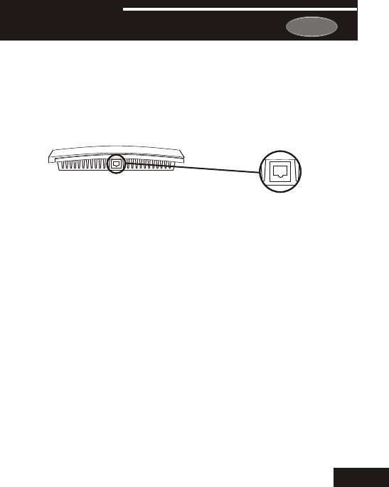
Page 23.1
SECTION 23
AccessoriesAccessories
RJ11 Type Jack
The Accessory Port is located on
the bottom of the thermostat.
EZ PROGRAMMER (optional accessory) - When the EZ
is connected, the thermostat Time Period
Advanced Setup Programming can be stored into
memory. This information can then be uploaded to
other 33CS250-01 thermostats.
Programmer
Programming and
the EZ
Programmer’s
For more information see the
instruction sheet for the P/N 33CSPGMR-01.
23
IR RECEIVER / REMOTE CONTROL (optional accessory) - When the
IR Receiver is connected, the thermostat can be controlled using
an IR Remote Control. The thermostat may also interface with
other wireless systems in your home. For more information see the
instruction sheet for the IR Receiver (33CSIRRCVR-01).
ACCESSORY PORT - The RJ11 Jack is used to connect the
33CS450-01 to the IR Receiver P/N 33CSIRRCVR-01 for wireless
communication or the EZ Programmer P/N 33CSPGMR-01
for easy downloading or uploading of thermostat information.
Carrier
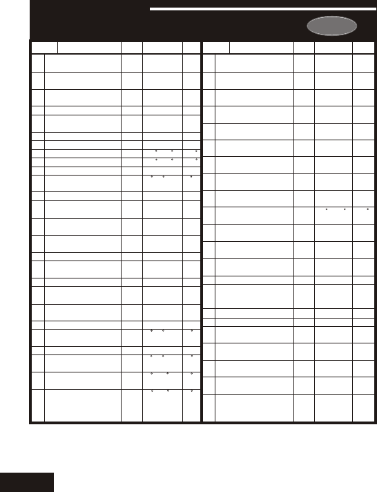
24
Description
Df*
Step# Range Step# Description
Range
Df*
2
2
Off
Off
NO
7
Mo
7am
9pm
80
No
Off
Yes
NO
Occ.
1
No
Off
- -
0
0
0
- -
1
2
3
4
5
6
7
8
9
10
11
12
13
14
15
16
17
18
19
20
21
22
23
24
25
26
Programmable
Thermostat
Auto-Changeover
Thermostat
Fan Off Delay
Fan Purge
Thermoglow
Backlight
F or C
Security Level
Max Heat Setpoint
Min Cool Setpoint
Cool to Dehumidify
Maximum Dehum
Overshoot
Reheat Operation
DEHUM Terminal
Polarity
Energy Watch -
Heat Timer
Energy Watch -
Cool Timer
Override Run-Time
Reset Service
Humidify Icon
Reset UV Light Icon
Heatpump Jumper
Setting
Reversing Valve
Jumper Setting
Electric Heat
Minimum Heat/Cool
Differential
Cycles Per Hour
Deadband/Temp.
Swing 1st Stage
Deadband/Temp.
Swing 2nd Stage
Deadband/Temp.
Swing 3rd Stage
Yes
Yes
0
0
Au-
to
F
0
80
65
Off
3
Off
NC
- -
- -
- -
- -
- -
- -
- -
- -
2
6
2
2
2
Yes/No
Yes/No
0, 30, 60,
90
0 - 3 hrs.
Auto/On/
Off
F/C
0 - 3
35 - 99
35 - 99
On/Off
0 - 5
On/Off
NO/NC
read only
read only
read only
read only
read only
read only
read only
read only
0 - 6
d1, d, 2-6
1 - 6
0 - 10
0 - 10
Pg#
4.2
4.3
7.3
7.4
8.2
8.2
8.4
8.4
8.4
10.4
10.4
10.5
10.6
11.2
11.3
11.4
11.5
11.6
12.2
12.2
12.3
13.2
13.3
13.5
13.5
13.5
0-60min
0-60min
On/Off
Off/Time/
Temp/Aux
NO/NC
7Day/
1Day
Mo - Su
24 Hour
24 Hour
35 -125
Yes/No
On/Off
Yes/No
NO/NC
Occ. 1/
Service
Pan
Yes/No
Off/On
read only
0 - 1950
0 - 1990
0 - 1990
- -
27
28
29
30
31
32
33
34
35
36
37
38
39
40
41
42
43
44
45
46
47
48
Minutes Between
Stage 1 & 2
Minutes Between
Stage 2 & 3
2nd Stage turn off at
setpoint
Programmable
Output
Programmable
Output Polarity
7 Day/1 Day
Programmable Output
Programmable Output
Output Day of the Week
Programmable Output
Start Time
Programmable Output
Stop Time
Programmable Output
Temp. Setpoint
Thermostat control
to RS1?
Thermostat Sensor
Averaging
Dry Contact
Operation
Dry Contact Polarity
Dry Contact
Programming
Light Activated
Energy Save
Reset Service Filter
Icon
Service Filter Run
Time Set
UV Light Run-Time
Set
Service Humidify
Run-Time Set
Viewing the Remote
Sensor
Temperature(s)
Pg#
13.6
13.6
13.7
14.3
14.4
14.4
14.4
14.4
14.5
14.6
15.3
15.4
16.2
16.2
16.3
17.2
18.1
19.2
19.2
19.3
19.4
22.4
Page 24.1
SECTION 24
Advanced Setup TableAdvanced Setup Table
*Df = Factory Default Setting
Carrier

Carrier
Page 25.1
dehum, 10.6
minutes of run-
time, 13.4, 13.6
21.5, 24.1
turn off
temperature,
13.7, 24.1
Y2 operation, 21.5
deadband, see
Deadband
droop, see Deadband
icon, 2.3
indicator, 2.2
mode, 1.3
overshoot, see
Overshoot
program, see Program
run-time, see Run-Time
setpoint, 1.3-1.4,
6.2-6.5
to dehumidify, see
Dehumidify
Condensate Drain Pan,
2.5, 16.3
Copy Function
see Program
Cycles Per Hour, 13.3,
24.1
Day,
electric/heat pump,
12.2
Accessory Port, 23.1
Alerts
see Run-Time
Auto
adjust temperature,
1.4, 4.8
changeover, 2.3, 4.5,
4.7, 24.1
differential, see
Differential
fan, 7.2
icon, 2.3
lockout, 4.3
mode, 1.3
AuxHeat icon, 2.5
Average
remote sensors, 15.4
thermostat sensor,
15.4
automatically, 15.4
b reversing valve, 12.2
Buttons
down, 1.2, 2.2, 8.3,
12.4
fan, 1.4, 2.2, 7.2,
12.4, 22.2
front panel, 2.2
humidity, 2.2, 5.3,
9.4, 10.4
Holiday, 2.2, 5.2,
15.3, 20.1
mode, 1.3, 2.2, 4.2,
8.3, 22.2
outside, 2.2, 5.2
Override, 2.2, 6.6
up, 1.2, 2.2, 8.3,
12.4
C, 8.2, 24.1
Calibration, 22.3
Celsius, 8.2
Clock
display, 2.3
setting, 1.2, 3.2
Compressor Lockout,
13.3
Cool
1st stage
deadband, see
Deadband
dehum, 10.6
minutes of run-
time, 13.4,
13.6, 24.1
2nd stage
deadband, see
Deadband
A
B
C
SECTION 25
Index Index
D
Carrier
Page 25.2
Fan,
off time delay, 7.3,
24.1
on icon, 1.4, 2.4, 7.2
purge, 7.4, 24.1
1st stage
deadband, see
Deadband
emergency heat,
button function, see
Buttons
on during heat, see
Electric Heat
run-time, 19.2
2nd stage heat, see
Emergency Heat
speed, see Dehumidify
unoccupied, 7.2
Fd, 22.2
Flashing Selection, 1.2
Gas Furnace
control the fan, 12.3
jumper, 12.2
Green Indicator, 2.2
Heat
display, 2.4
setting, 1.2, 3.2
Deadband
1st stage, 13.4-13.5,
24.1
2nd stage, 13.4-13.5,
21.3, 21.5, 24.1
3rd stage, 13.4-13.5,
21.3, 24.1
Dehumidify
cool to, 10.4, 24.1
Aux icon, 2.5, 10.5
DEHUM jumper,
10.6
icon, 2.5
setpoint, 10.3
Delay
fan-off, see Fan
time between stages,
see Time Delay
Differential
heat and cool, 13.2,
24.1
humidify and
dehumidify, 9.2,
10.2
Disabled Keypad
see Keypad Lockout
Drain Pan Overflow
Alarm, see Dry Contact
Dry Contact
occupied 1, 16.3, 24.1
operation, 16.2,
24.1
polarity, 16.2, 24.1
service pan, 16.3
Random start, 16.4
Economizer
ECON, 21.5
operation, 21.5
EH, 12.4
Electric Heating
AuxHeat icon, 2.5
jumper setting, 12.3
24.1
reheat, 10.5
W2, 10.5
Emergency Heat,
12.4
Energy Save, 18.1
Energy Watch
cool, 11.3, 24.1
heat, 11.2, 24.1
EZ Programmer, 23.1
F, 8.2, 24.1
Factory Defaults
caution, ii
settings, 22.2
resetting, 22.2
Fahrenheit, 8.2
F
G
H
SECTION 25
Index Index
SECTION 25
Index Index
E

Carrier
Page 25.3
Jumpers
DEHUM, 21.4
ECON, 21.5
ELEC, 12.3
electric heat, 12.3,
24.1
gas electric, 12.2, 24.1
heat pump, 12.2, 24.1
HUM, 9.2, 21.4
programmable output,
14.2
reversing valve, 12.2,
24.1
W3, 21.3
Y2, 21.5
Keypad Lockout, 2.4,
8.3
LCD, 2.2
Light
activated, 17.2-17.3,
24.1
12.4
minutes of run-
time, 13.4, 13.6,
24.1
2nd stage
deadband, see
Deadband
emergency heat,
12.4
minutes of run-
time, 13.4, 13.6,
24.1
3rd stage
deadband, see
Deadband
W3, 21.3
AuxHeat icon, 2.5
deadband, see
Deadband
droop, see Deadband
icon, 2.3
indicator, 2.2
mode, 1.3
program, see Program
run-time, see Run-
Time
setpoint, 1.3-1.4,
6.2-6.3
Heat Pump
AuxHeat, 2.5
emergency heat,
12.4
jumper setting, 12.2
electric/heat pump,
12.2-12.3
Hi
icon, 2.5, 5.2
security setpoint, 8.4
temperature, 5.2
Holiday
button, see Buttons
light activation, 17.2
mode, 20.1-20.2
programming, 20.1-
20.2
setpoints, 21.1
Humidify
icon, 2.5
service, 11.5, 19.4,
24.1
setpoint, 9.3
Humidity Module
connector, 9.2
installation, 9.2
jumper setting, 9.2
required for, 5.3,
9.1, 9.3, 10.1-10.3,
21.4, 22.3
Internet-based
Operation,
see Programmable
Output
IR Receiver, 23.1
IR Remote Control,
23.1
I
SECTION 25
Index Index
K
L
J

TOTALINE
Carrier
Page 25.4
Off Mode, 1.3, 2.3
Outdoor,
see Outside
Outside
button, see Buttons
icon, 2.3
sensor, 2.3, 5.2, 13.1-
13.2, 15.2, 22.4
Pan, Service
see Dry Contact
Phone-based operation
see Programmable
Output
Polarity, see Dry Contact
Preoccupancy Fan
Purge Timer, see Fan
Program,
copy, 6.4-6.5
viewing temperature,
2.3, 5.2, 22.4
Override
button, see Buttons
daily schedule, 6.6
icon, 2.3
timer, 6.6
viewing run-time,
11.4, 24.1
Overshoot, 10.4, 24.1
random start, 16.4
sensor, 17.2
adjustment, 17.3
Locked Indication
see Keypad Lockout
Lo
icon, 2.5, 5.2
security setpoint, 8.4
temperature, 5.2
Manual
changeover, 4.4, 4.6
cool, 4.3
heat, 4.3
Maximum Outdoor
Temperature, see Hi
Minimum Outdoor
Temperature,
see Lo
MISC
jumper, see Jumpers
output, 21.2-21.5
Mode, 1.3, 2.3
Multi-stage
Operation, 13.4
Non-Programmable
Thermostat, 4.2,
4.4-4.5
Normally
Open/Closed,
dry contact, 16.2
programmable
output, 14.4,
14.6-14.7
dehum terminal,
10.6
O Reversing Valve,
12.2
Occupied 1
Dry contact, 16.3
light activated, 17.2-
programming, 6.2-
6.5
daily schedule, see
Program
economizer
operation, 21.5
energy save, 18.1
icon, 1.3, 2.4
17.3
mode, 1.3, 4.6-4.7
override, 6.6
programming
worksheet, back
page
random start, 16.4
MO
SECTION 25
Index Index
SECTION 25
Index Index
P
N

Carrier
Page 25.5
cool, 11.3, 24.1
heat, 11.2, 24.1
Humidification,
11.5, 24.1
override, 11.4,
UV light, 11.6
Schedule, Daily,
see Program
2nd stage turn off
temperature,
13.7, 24.1
Security
level, 8.4, 24.1
setpoints, 8.4, 24.1
Sensor
outside, see Outside
remote, see Remote
thermostat, see
Thermostat
Service
filter icon, see Reset
humidify icon, see
Reset
pan icon, see Dry
Contact
UV light, see Reset
Set Clock, see Clock
Setpoint
cool, see Cool
dehumidification, 10.3
daily schedule, 6.2-6.4
mode, 1.3, 4.4-4.8
on at all times, 8.4
On icon, 2.3
override, see Override
setpoint limits, 8.4
tips, 6.5
worksheet, back page
Programmable Output
Internet/phone
control, 14.7
jumper setting, 14.2,
21.3
temperature-based
control, 14.6
time-based control,
14.3
Programmable
Thermostat, 4.2
Random Start, 16.4
Red Indicator, 2.2
Reheat
during cool to
dehumidify, 10.5
electric heating, 10.5
function, 10.5
W2, 10.5
Remote Sensor
averaging, 15.4
calibrate, 22.3
Control to, 15.3-
15.4, 22.1
degree icon blink,
15.2-15.4
icon, 2.5
outside temperature,
see Outside
read to, 15.3
viewing, 22.4, 24.1
wiring, 15.2
Reset
thermostat settings,
see Factory Defaults
run-time
fan/filter, 19.2,
24.1
humidify, 19.4,
UV light, 19.3,
24.1
RS1, see Remote
Sensor
RS2, see Outside
Sensor
Run-Time
resetting, see Reset
setting,
humidifier, 19.4,
24.1
service filter, 19.2
24.1
UV light, 19.3,
24.1
viewing,
R
S
SECTION 25
Index Index
Carrier
Page 25.6
10.5-10.6
heat, see Heat
holiday, 20.1
humidification, 9.4
occupied, 6.2
programmable output,
14.6
security, 8.4
unoccupied, 6.2-6.3
Setup Icon, 2.4
Simplest Operation,
4.2-4.3
Smart Fan, 7.2
Smart Recovery, see
Energy Save
Terminal, MISC, see
MISC
Thermostat Sensor
averaging, 15.4, 24.1
calibrate, 22.3
Time, see Clock
Time Delay,
compressor lockout,
13.3
cycles per hour,
13.3, 24.1
1st to 2nd stage,
13.6, 24.1
2nd to 3rd stage,
13.6, 24.1
Time Schedule, see
Program
Unoccupied
icon, 2.3
operation, 6.5
override, see
Override
setpoint, 6.2-6.3
UV Light
icon, 2.5
resetting, see Reset
run-time, see Run-
Time
setting, see Run-Time
W3, see Jumpers
Warranty, 26.1
Web, 14.7
Y2, see Jumpers
T
W
SECTION 25
Index Index
SECTION 25
Index Index
U
Y

THIS WARRANTY DOES NOT INCLUDE LABOR OR OTHER COSTS incurred for diagnosing,
repairing, removing, installing, shipping, servicing or handling of either defective parts or
replacement parts. Such costs may be covered by a separate warranty provided by the installer.
THIS WARRANTY APPLIES ONLY TO PRODUCTS IN THEIR ORIGINAL INSTALLATION
LOCATION AND BECOMES VOID UPON REINSTALLATION.
LIMITATIONS OF WARRANTIES – ALL IMPLIED WARRANTIES (INCLUDING IMPLIED
WARRANTIES OF FITNESS FOR A PARTICULAR PURPOSE AND MERCHANTABILITY) ARE
HEREBY LIMITED IN DURATION TO THE PERIOD FOR WHICH THE LIMITED WARRANTY
IS GIVEN. SOME STATES DO NOT ALLOW LIMITATIONS ON HOW LONG AN IMPLIED
WARRANTY LASTS, SO THE ABOVE MAY NOT APPLY TO YOU. THE EXPRESSED
WARRANTIES MADE IN THIS WARRANTY ARE EXCLUSIVE AND MAY NOT BE ALTERED,
ENLARGED, OR CHANGED BY ANY DISTRIBUTOR, DEALER, OR OTHER PERSON
WHATSOEVER.
ALL WORK UNDER THE TERMS OF THIS WARRANTY SHALL BE PERFORMED DURING
NORMAL WORKING HOURS. ALL REPLACEMENT PARTS, WHETHER NEW OR
REMANUFACTURED, ASSUME AS THEIR WARRANTY PERIOD ONLY THE REMAINING
TIME PERIOD OF THIS WARRANTY.
THE MANUFACTURER WILL NOT BE RESPONSIBLE FOR:
1. Normal maintenance as outlined in the installation and servicing instructions or owner ’s
manual, including filter cleaning and/or replacement and lubrication.
2. Damage or repairs required as a consequence of faulty installation, misapplication, abuse,
improper servicing, unauthorized alteration or improper operation.
3. Failure to start due to voltage conditions, blown fuses, open circuit breakers or other
damages due to the inadequacy or interruption of electrical service.
4. Damage as a result of floods, winds, fires, lightning, accidents, corrosive environments or
other conditions beyond the control of the Manufacturer.
5. Parts not supplied or designated by the Manufacturer, or damages resulting from their use.
6. Manufacturer products installed outside the continental U.S.A., Alaska, Hawaii, and
Canada.
7. Electricity or fuel costs or increases in electricity or fuel costs for any reason whatsoever
including additional or unusual use of supplemental electric heat.
8. ANY SPECIAL INDIRECT OR CONSEQUENTIAL PROPERTY OR COMMERCIAL
DAMAGE OF ANY NATURE WHATSOEVER. Some states do not allow the exclusion of
incidental or consequential damages, so the above may not apply to you.
This warranty gives you specific legal rights and you may also have other rights which may vary
from state to state.
Page 26.1
Section 26
WarrantyWarranty
Carrier
Five-Year Warranty - This Product is warranted to be free from defects in material and
workmanship. If it appears within five years from the date of original installation, whether or
not actual use begins on that date, that the product does not meet this warranty, a new or
remanufactured part, at the manufacturer’s sole option to replace any defective part, will be
provided without charge for the part itself provided the defective part is returned to the
distributor through a qualified servicing dealer.
Programming Worksheet see Section 6
No
Yes
No
Yes
No
Yes
No
Yes
No
Yes
No
Yes
F
R
I
D
A
Y
T
U
R
A
S
D
A
Y
Copy Fri Sat
Copy Tue Wed
Copy Thu Fri
S
U
N
D
A
Y
Copy Sat Sun
Copy Wed Thu
W
E
N
E
S
D
D
A
Y
T
U
R
H
S
D
A
Y
Copy Mon Tue
M
O
N
D
A
Y
T
U
E
S
D
A
Y
DAY PERIOD HEAT
START TIME COOL
Unoccupied
Occupied 1
Occupied 2
Occupied 3
Printed on recycled paper.
P/N 88-506 Rev. 5
Unoccupied
Occupied 1
Occupied 2
Occupied 3
Unoccupied
Occupied 1
Occupied 2
Occupied 3
Unoccupied
Occupied 1
Occupied 2
Occupied 3
Unoccupied
Occupied 1
Occupied 2
Occupied 3
Unoccupied
Occupied 1
Occupied 2
Occupied 3
Unoccupied
Occupied 1
Occupied 2
Occupied 3
