Carrier 40Qnc Users Manual Q 9SI
40QNC to the manual dc7342a5-a949-4805-ba10-f9c82f673d2f
2015-01-24
: Carrier Carrier-40Qnc-Users-Manual-310612 carrier-40qnc-users-manual-310612 carrier pdf
Open the PDF directly: View PDF ![]() .
.
Page Count: 24
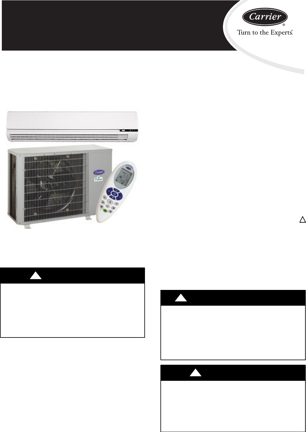
40QNC / 38HDF
40QNQ / 38QRF
High---Wall Duct Free Split System
Sizes 018 to 036
Installation Instructions
40QNC, QNQ Unit
NOTE: Read the entire instruction manual before starting the
installation.
!WARNING
UNIT OPERATION AND SAFETY HAZARD
Failure to follow this warning could result in personal injury or
equipment damage.
Puron refrigerant systems operate at higher pressures than
standard R--22 systems. To avoid damage to the unit or
possible personal injury, do not use R--22 service equipment or
components on Puron refrigerant equipment.
SAFETY CONSIDERATIONS
Improper installation, adjustment, alteration, service, maintenance,
or use can cause explosion, fire, electrical shock, or other
conditions which may cause death, personal injury, or property
damage. Consult a qualified installer, service agency, or your
distributor or branch for information or assistance. The qualified
installer or agency must use factory--authorized kits or accessories
when modifying this product. Refer to the individual instructions
packaged with the kits or accessories when installing.
Follow all safety codes. Wear safety glasses, protective clothing,
and work gloves. Use quenching cloth for brazing operations.
Have fire extinguisher available. Read these instructions
thoroughly and follow all warnings or cautions included in
literature and attached to the unit. Consult local building codes and
current editions of the National Electrical Code ( NEC ) NFPA 70.
In Canada, refer to current editions of the Canadian electrical code
CSA 22.1.
Recognize safety information. This is the safety--alert symbol !!
When you see this symbol on the unit and in instructions or
manuals, be alert to the potential for personal injury. Understand
these signal words; DANGER, WARNING, and CAUTION. These
words are used with the safety--alert symbol. DANGER identifies
the most serious hazards which will result in severe personal injury
or death. WARNING signifies hazards which could result in
personal injury or death. CAUTION is used to identify unsafe
practices which would result in minor personal injury or product
and property damage. NOTE is used to highlight suggestions
which will result in enhanced installation, reliability, or operation.
!WARNING
ELECTRICAL SHOCK HAZARD
Failure to follow this warning could result in personal
injury or death.
Before installing, modifying, or servicing system, main
electrical disconnect switch must be in the OFF
position. There may be more than 1 disconnect switch.
Lock out and tag switch with a suitable warning label.
PERSONAL INJURY AND EQUIPMENT DAMAGE
HAZARD
Failure to follow this caution may result in personal injury
and / or equipment damage.
DO NOT operate the unit without a filter or with grille
removed.
CAUTION
!
2
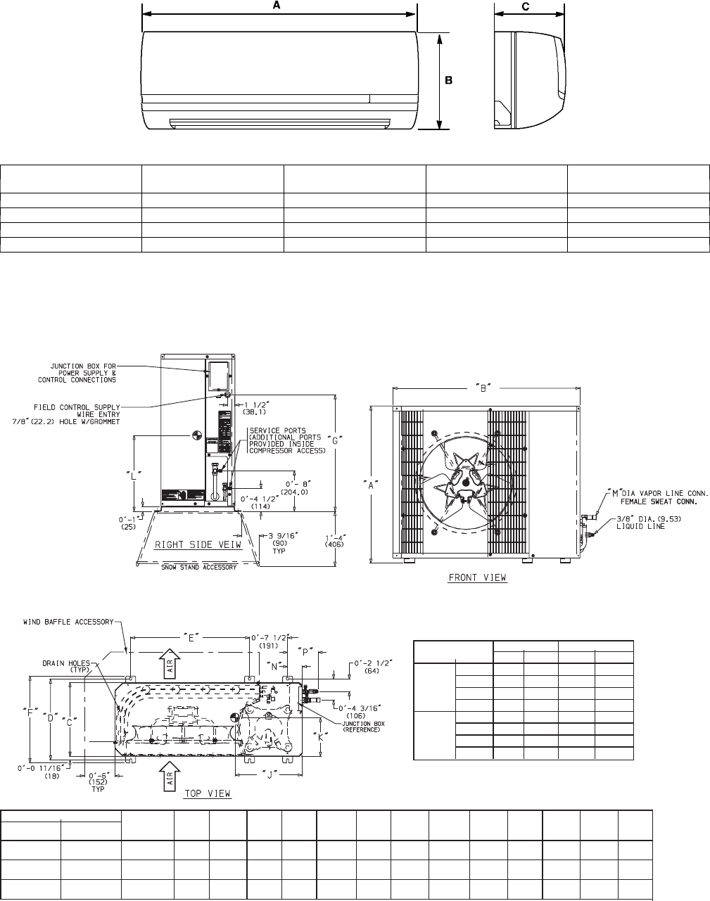
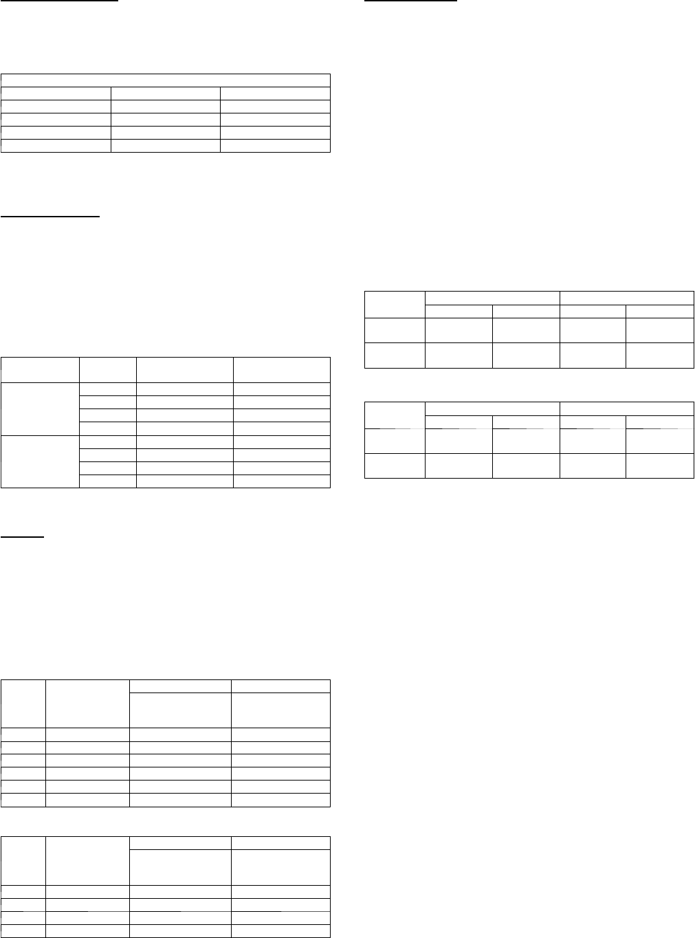
DIMENSIONS -- INDOOR
A08433
Model Size W
In. (mm)
H
In. (mm)
D
In. (mm)
Operating Weight
lb (kg)
18k 42.5 (1080) 11.6 (295) 7.9 (201) 31 (14.1)
24k 42.5 (1080) 11.6 (295) 7.9 (201) 31 (14.1)
30k 57.5 (1461) 13.4 (340) 9.5 (241) 51 (23.2)
36k 57.5 (1461) 13.4 (340) 9.5 (241) 51 (23.2)
Fig. 1 -- 40QNC,QNQ Unit Dimensions
DIMENSIONS -- OUTDOOR
(FIELD PROVIDED AND INSTALLED)
NOTE: Dimensions shown in feet-inches. Dimensions in ( ) are millimeters.
UNIT MODELS CHASSIS
SIZE
(Reference)
ABCD E FG H J KL NP
38HDF
Unit Size
38QRF
Unit Size
018 018 02′-1
1
/
8
″3′-0
15
/
16
″1′-2
9
/
16
″1′-4″1′-11
7
/
16
″1′-5
3
/
16
″1′-5
1
/
8
″1′-10″1′-1″0′-6
5
/
8
″0′-11
1
/
4
″0′-2
15
/
16
″0′-6″
(638.2) (938.2) (369.9) (406.4) (595.3) (436.6) (435) (559.1) (330.2) (168.3) (285.8) (75) (152.4)
024,030 024 0.6 2′-7
1
/
8
″3′-0
15
/
16
″1′-2
9
/
16
″1′-4″1′-11
7
/
16
″1′-5
3
/
16
″1′-11
1
/
8
″2′-4″1′-2″0′-6
3
/
4
″0′-11
5
/
8
″0′-2
15
/
16
″0′-6″
(790.6) (938.2) (369.9) (406.4) (595.3) (436.6) (587.4) (711.5) (355.6) (171.5) (295.3) (75) (152.4)
036 030,036 1.0 3′-1
3
/
16
″3′-8
9
/
16
″1′-5
1
/
16
″1′-6
7
/
16
″2′-6
1
/
2
″1′-7
5
/
8
″2′-5
3
/
16
″2′-10
1
/
16
″1′-1
11
/
16
″0′-8
1
/
8
″1′-3
7
/
8
″0′-3
7
/
16
″0′-6
1
/
2
″
(944.6) (1131.9) (433.4) (468.3) (774.7) (498.5) (741) (865.5) (347.7) (206.4) (403.2) (88) (165.4)
UNIT SIZE M OPERATING WT
in. mm lb kg
38HDF
018
5
/
8
15.88 166 75.3
024
5
/
8
15.88 176 79.8
030
3
/
4
19.05 187 84.8
036
3
/
4
19.05 250 113.4
* Male flare connection for Heat Pumps
FEMALE SWEAT CONN.*
38QRF
018
5
/
8
15.88 166 75.3
024
5
/
8
15.88 176 79.8
030
3
/
4
19.05 187 84.8
036
3
/
4
19.05 232 105.2
A08434
Fig. 2 -- 38HDF, QRF Unit Dimensions
3
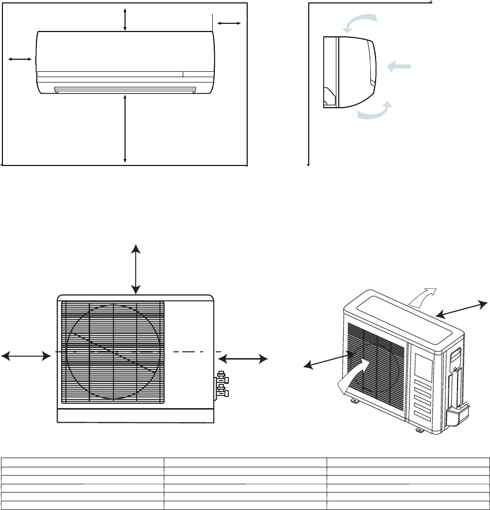
CLEARANCES -- INDOOR
min.
min.
min.
min.
4in.
4in.
80 in.
8in.
A08357
Fig. 3 -- 40QNC,QNQ Unit Clearances
CLEARANCES -- OUTDOOR
A
DB
Air-inlet
Air-outlet
C
E
A08436
UNIT Coil Facing Wall --- in. (mm) Fan Facing Wall --- in. (mm)
A24 (610) 24 (610)
B36 (914) 36 (914)
C36 (914) 8 (203)
D6 (152) 8 (203)
E6 (152) 36 (914)
Fig. 4 -- Outdoor Unit Clearance
4
These installation instructions cover the installation of the matched
systems listed in table 2.
Parts List
Indoor Unit
The following items are included with the indoor unit:
Table 1 – Installation Materials
Description Qty Usage
Wall Mounting
Bracket 1For Indoor Unit Installation
Screws, 4XL10 2For Attaching The Remote Control
Holder To The Wall
Screws, 5XL25 5/14* For Attaching The Mounting Bracket To
The Wall
Remote Control 1For Controlling Unit
Remote Control
Holder 1Holder For Remote Control
* 5 screws for unit sizes 18 and 24. 14 screws for unit sizes 30 and 36.
Outdoor Unit
The following items are included with the outdoor unit:
38HDF018-036
A09499
Fig. 5 -- 38HDF018--036
A09500
Fig. 6 -- 38QRF018--036
Model Filter Drier Piston
Cap Pistons* Flare
Connector
38HDF n n n n
38QRF n n (qty 2) n n (qty 3)
* Multiple pistons. Quantity varies with size.
Table 2 – Matched Systems
System
Ty p e
Nominal
Capacity
Outdoor
Unit
Indoor
Unit
Cooling
Only
018 3 8 H D F 0 1 8 --- --- --- 3 40QNC018024--- --- ---3
024 3 8 H D F 0 2 4 --- --- --- 3 40QNC018024--- --- ---3
030 3 8 H D F 0 3 0 --- --- --- 3 4 0 Q N C 0 3 0 --- --- --- 3
036 38HDF036--- --- ---3/5/6 4 0 Q N C 0 3 6 --- --- --- 3
Heat
Pump
018 3 8 Q R F 0 1 8 --- --- --- 3 4 0 QN Q 0 1 8 --- --- --- 3
024 3 8 Q R F 0 2 4 --- --- --- 3 4 0 QN Q 0 2 4 --- --- --- 3
030 3 8 Q R F 0 3 0 --- --- --- 3 4 0 QN Q 0 3 0 --- --- --- 3
036 38QRF036--- --- ---3/5/6 4 0 Q N Q 0 3 6 --- --- --- 3
SYSTEM REQUIREMENTS
Clearances
Allow sufficient space around the indoor and outdoor unit for
proper airflow circulation and servicing. Refer to Fig. 3 and Fig. 4
for minimum required clearances.
Piping: Piping and insulation is field supplied.
Piping Lengths
The minimum length between the indoor and outdoor units is 10 ft
(3 m). Refer to table 3 for the maximum lengths allowed.
Table 3 – Maximum Refrigerant Line Lengths
Unit
Size
Max Line
Length ft(m)
Max Elevation (ID
over OD) ft(m)
Max Elevation (OD
over OD) ft(m)
18K 200 (61) 65 (19.8) 200 (61)
24K 200 (61) 65 (19.8) 200 (61)
30K 200 (61) 65 (19.8) 200 (61)
36K 200 (61) 65 (19.8) 200 (61)
Note:For lengths greater than 25 ft (7.6 m), refer to the Duct Free Long
Line Guide.
Pipe Sizes
Refer to table 4 for pipe sizes.
Table4–PipeSizes
Pipe Sizes (in)
Unit Size M i x P h a s e --- i n Vapor --- in
18K 3/8 5/8
24K 3/8 5/8
30K 3/8 3/4
36K 3/8 3/4
Note:Both lines need to be insulated using at least 1/2 inch closed foam
insulation.
Condensate Drain Pipe Sizes
Refertotable5fortherequiredsizes.
Table 5 – Drain Pipe Sizes
Unit Size Outside Diameter --- in Inside Diameter --- in
18K 5/8 7/16
24K 5/8 7/16
30K 3/4 5/9
36K 3/4 5/9
Note:Do not trap condensate pipe.
5
Refrigerant Charge
The 38HDF and 38QRF units can be matched with multiple
outdoor units and thus additional charge might be required when
matched with the 40QNC or 40QNQ units.
Table 6 – Additional Charge
Additional Charge lb (kg)
Unit Size 38HDF 38QRF
018 1.2 (0.55) 0.8 (0.36)
024 1.0 (0.45) 0.5 (0.23)
030 2.4 (1.1) 0
036 0 0
Note:The above additional charge is required amount for line lengths up to
25 ft (7.6 m). For line lengths exceeding 25 ft (7.6 m), additional charge will
be required. Refer to the Duct Free Splits Long Line Guide.
Metering Device
The metering device(s) for these systems is a type B Accurator
installed with the outdoor unit. One Accurator is required for the
cooling only system and two are required for the heat pump
systems. The Accurators are supplied with the outdoor unit.
However, since the same outdoor unit can be matched with
multiple indoor units, the correct Accurator must be selected. Refer
to Table 7 for the correct Accurator size.
Table 7 – Accurator Sizes
System Type Size Cooling
Accurator
Heating
Accurator
Cooling Only
018 49 ---
024 55 ---
030 63 ---
036 70 ---
Heat Pumps
018 49 45
024 55 49
030 63 53
036 70 63
Power and Connecting Cables -- Field Supplied
Power:
SThe indoor and outdoor units require a dedicated power supply.
SConsult local building codes, NEC (National Electric Code) or
CEC (Canadian Electric Code) for any special requirements.
SUse Table 8 for the electrical requirements for the outdoor units
and Table 9 for the indoor units to correctly size the cables and
disconnect switches.
Table 8 – 38HDF / QRF Electrical Requirements
Unit
Size Voltage
38HDF 38QRF
Min Ckt Amps/
Fuse HACR Bkr
Amps
Min Ckt Amps/
Fuse HACR Bkr
Amps
018 208/230---1---60 12.1/20 12.1/20
024 208/230---1---60 16.8/25 16.8/25
030 208/230---1---60 18.4/30 18.4/30
036 208/230---1---60 23.8/40 23.8/40
036 208/230---3---60 18.0/30 18.0/30
036 4 6 0 --- 3 --- 6 0 8.3/15 8.3/15
Table 9 – 40QNC / QNQ Electrical Requirements
Unit
Size Voltage
40QNC 40QNQ
Min Ckt Amps/
Fuse HACR Bkr
Amps
Min Ckt Amps/
Fuse HACR Bkr
Amps
018 208/230---1---60 0.48/15 0.48/15
024 208/230---1---60 0.48/15 0.48/15
030 208/230---1---60 0.48/15 0.48/15
036 208/230---1---60 0.55/15 0.55/15
Control Wiring
Thermostat wires should be used for control wiring between the
indoor and outdoor units. A two conductor cable is required for
the cooling only units and a seven conductor cable is required on
heat pumps. 18 AWG is recommended for any length up to 50 ft
(15.2 m). 16 AWG is recommended for lengths between 50 and
200 ft (15.2 and 61.0 m).
User Interface
The indoor unit is supplied with a wireless remote control. The
following accessories are also available
SWall mounted control. Up to 6 units can be daisy chained and
controlled by one wired control.
SZone manager capable of controlling up to 32 units divided up
to 8 different zones.
Operating Range
Ensure that the system operates within the application guidelines
shown in Table 10.
Cooling Operating Range
Maximum Minimum
DB ° F (° C) WB ° F (° C) DB ° F (° C) WB ° F (° C)
Outdoor
Unit 125 (51.7) --- --- 55 (12.8) --- ---
Indoor
Unit 90 (32.2) 74 (23.3) 62 (17.0) 56 (13)
Heating Operating Range
Maximum Minimum
DB ° F (° C) WB ° F (° C) DB ° F (° C) WB ° F (° C)
Outdoor
Unit 75 (23.9) 67 (19.4) 17 (---8.3) --- ---
Indoor
Unit 81 (27.2) --- --- 62 (17.0) --- ---
Accessories
An extensive list of field installed accessories is available for both
indoor and outdoor units. Identify what accessories, if any, are
required for the application at hand and consult the separate
installation instructions for the accessories. Some of the
accessories, especially on the indoor units, can be installed much
easier if planned ahead.
6
INSTALLATION
Complete Pre--installation Checks
1. Unpack Unit -- Store the indoor and outdoor units in the
original packaging until it is moved to the final site for in-
stallation.
2. Inspect Shipment -- Upon receipt of shipment, check the
indoor and outdoor units for damage. If there is any dam-
age, forward claim papers directly to the transportation
company. Manufacturer is not responsible for damage in-
curred in transit.
3. Inspect Parts Supplied With Units – Check all items
against parts list (see Table 1). If any items are missing, noti-
fy your distributor or Carrier office. To prevent loss or
damage, leave all parts in original packages until installa-
tion.
Consider System Requirements
1. Consult local building codes and NEC for special installa-
tion requirements.
2. When deciding the location of the indoor and outdoor units,
ensure that the piping run does not exceed the allowed dis-
tances listed in Table 3.
3. Make sure the indoor and outdoor units are easily accessible
to electrical power.
4. Allow sufficient clearances for airflow, wiring, refrigerant
piping, and servicing the unit. See Fig. 3 and Fig. 4.
5. Condensate piping can be directed through the inside wall
to an approved drain or straight outside.
INSTALL INDOOR UNIT
Plan the installation carefully before you begin.
1. Select indoor unit location.
a. A location that can bear the weight of the unit.
b. Do not install indoor units near a direct source of heat
such as direct sunlight or a heating appliance.
c. Do not install units too close to humid conditions.
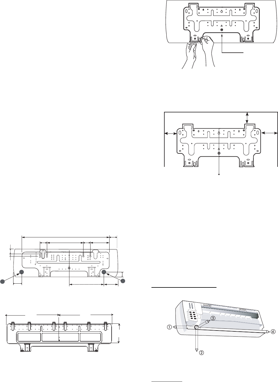
2. Install Mounting Plate
The factory supplied mounting plate will look like one of
the following depending on the size of the unit.
2.1"
(53.3)
14.9" (378.5)
3.5"
(88.9)
2.8"
(71.1)
2.8"
(71.1)
B
5.1”
(129.5)
13.8" (130.5)
A
2"
(50.8)
7.7" (195.6)
35.4” (899.2)
2.1"
(53.3)
1"
(25.4)
Note: Numbers in ( ) = mm
A09046
Fig. 7 -- 40QNC, QNQ018,024 Mounting Plate
27.1”
(688.3)
27.2”
(690.9)
8.4” (213)
Measurements in ( ) = mm
A09047
Fig. 8 -- 40QNC, QNQ030, 036 Mounting Plate
Before mounting the 40QNC, QNQ unit on the wall mounting
bracket, consider how the refrigerant piping will be routed.
Complete the following when installing the wall mounting bracket:
a. Carefully remove the mounting plate which is attached
to the back of the unit by removing any screws and
pushing at the indicated pressure points at the bottom of
the unit.
Remove Screw
A09048
Fig. 9 -- Mounting Plate Screw Location
b. The mounting plate should be located horizontally and
level on the wall. All minimum spacing shown below
should be maintained.
12”
(304.8)
min.
Plumb line
5” (127) min.
18”
(457.2)
min.
Note: Numbers in ( ) = mm
A09049
Fig. 10 -- Minimum Spacing
c. Install the wall mounting bracket in a location that is
strong enough to withstand the weight of the unit.
d. If the wall is block, brick, concrete or similar material,
drill 0.2 in (5 mm) diameter holes and insert anchors for
the appropriate mounting screws.
e. Fasten the wall hanging bracket to the wall with 4 or
more screw anchors through the holes near the outer
edge of the bracket.
f. Install the wall hanging bracket flush to the wall, and
ensure the bracket does not move.
3. Drill hole in wall for interconnecting piping, drain, and wir-
ing
Refrigerant Line Routing
Piping for indoor units can be routed as shown in Fig. 11.
A08358A
Fig. 11 -- Refrigerant Line Routing
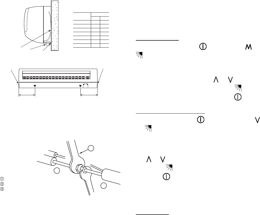
Rear Piping
Determine the pipe hole position using the mounting plate as a
template. Drill a 2--1/2 inch (63.5 mm) diameter hole in the wall at
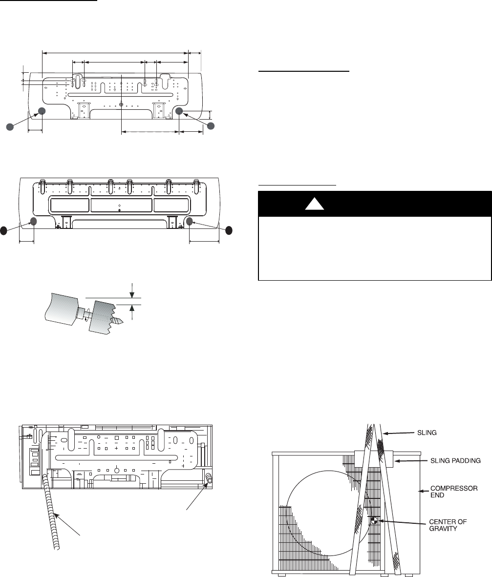
7
point A or B as shown in Fig. 12 or Fig. 13. Drill the hole at a
slope so that the outside end is 1/2 inch (13 mm) lower than inside
end to ensure optimal drainage. Refer to Fig. 14.
Side Or Bottom Piping
Remove the knockout in the unit and drill a 2--1/2 inch (63.5 mm)
hole where the pipe penetrates the structure using the guides given
above.
2.1"
(53.3)
14.9" (378.5)
3.5"
(88.9)
2.8"
(71.1)
2.8"
(71.1)
B
5.1”
(129.5)
13.8" (130.5)
A
2"
(50.8)
7.7" (195.6)
35.4” (899.2)
2.1"
(53.3)
1"
(25.4)
Note: Numbers in ( ) = mm
A09046
Fig. 12 -- 40QNC, QNQ018, 024 Mounting Plate
2" 5.1"
B
A
A09050
Fig. 13 -- 40QNC, QNQ030, 036 Mounting Plate
1/2 in. (13 mm)
Min.
INDOOR OUTDOOR
A07371
Fig. 14 -- Drill Hole at Slope
4. Relocate drain connection if necessary -- Determine if the
installation requires a left or a right hand drain exit and relo-
cate the drain hose if necessary as shown in Fig. 15.
Drain Hose
Drain Cap
A08362
Fig. 15 -- Drain Hose and Cap Location
NOTE: If the condensate pump accessory is to be used, the drain
hose can be cut to provide space for the space for the condensate
pump reservoir in the back of the unit. The reservoir must be
installed at this time. Please refer to installation instructions
provided with the condensate pump accessory.
5. Place unit on a clean surface until you are ready to connect
the piping and wiring.
INSTALL OUTDOOR UNIT
The outdoor units can be installed on the ground, on the roof, or
mounted on a wall.
NOTE: Install the unit so that the coil does not face into
prevailing winds. If this is not possible and constant wind winds
above 25 mph are expected, use accessory wind baffle. See
installation instructions provided with accessory kit. Wind baffles
should also be used on all units with accessory low ambient
temperature control.
Mounting on Ground
1. Mount unit on a solid level concrete pad.
2. If a heat pump is being installed, use a field-- provided snow
stand or ice rack where prolonged subfreezing temperatures
or heavy snow occurs.
3. Position unit so water or ice from roof does not fall directly
onto unit.
4. On cooling only units, an accessory stacking kit can be used
when units are to be stacked. See installation instructions
provided with the accessory kit.
Mounting on Roof
PERSONAL INJURY AND/OR EQUIPMENT
DAMAGE HAZARD
Failure to follow this caution may result in personal injury
and / or equipment damage.
Be sure unit panels are securely in place prior to rigging.
CAUTION
!
1. Rig the unit. Keep the unit upright and lift using a sling.
Use cardboard or padding under the sling, and spreader bars
to prevent sling damage to the unit. See Fig 16. See Fig. 2
for center of gravity reference
2. Mount unit on a solid concrete pad or platform.
3. Isolate unit and piping from structure
4. If a heat pump is being installed, use a field-- provided snow
stand or ice rack where prolonged subfreezing temperatures
or heavy snow occurs.
5. On cooling only units, an accessory stacking kit can be used
when units are to be stacked. See installation instructions
provided with accessory kit.
A07396
Fig. 16 -- Lifting Unit with Sling
8
Mounting Unit on Wall
The units can also be mounted on the wall using the accessory
mounting kit.
Complete Outdoor Refrigerant Piping Connec-
tions
Follow the following general guidelines:
1. Use refrigerant grade field – supplied tubing.
Refer to Table 4 for the correct line sizes.
2. Do not use less than 10 ft (93.05 m) of interconnecting
tubing.
CAUTION
!
UNIT DAMAGE HAZARD
Failure to follow this caution may result in equipment
damage or improper operation.
If any section of pipe is buried, there must be a 6 in. (152.4
mm) vertical rise to the valve connections on the outdoor
unit. If more than the recommended length is buried,
refrigerant may migrate to cooler, buried section during
extended periods of system shutdown. This causes
refrigerant slugging and could possibly damage the
compressor at start--up.
When more than 80 ft (24.4 m) of interconnecting tubing is used,
consult the Duct--Free Split System Long Line Application Guide
for required accessories.
3. Insulate both lines. A minimum of 1/2 inch foam pipe insu-
lation is recommended.
4. Run the refrigerant tubes as directly as possible and avoid
unnecessary turns and bends.
5. Suspend refrigerant tubes to avoid damage to insulation or
tubes so they do not transmit vibration to the structure.
6. When passing refrigerant tubes through the wall, seal the
opening so rain and insects do not enter the structure. Leave
some slack in refrigerant tubes between structure and out-
door unit to absorb vibration.
NOTE: A fusible plug is located in unit suction line; do not cap
this plug. If local codes require additional safety devices, install as
directed.
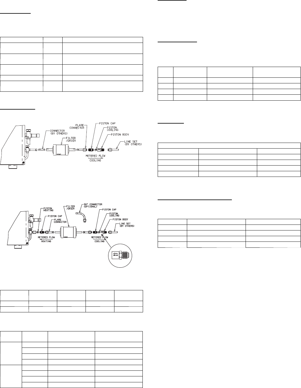
Connection at Outdoor Unit
CAUTION
!
UNIT DAMAGE HAZARD
Failure to follow this caution may result in equipment damage
or improper operation.
To prevent damage to unit or service valves observe the
following:
SA brazing shield MUST be used.
SWrap service valves with wet cloth or use a heat sink
material.
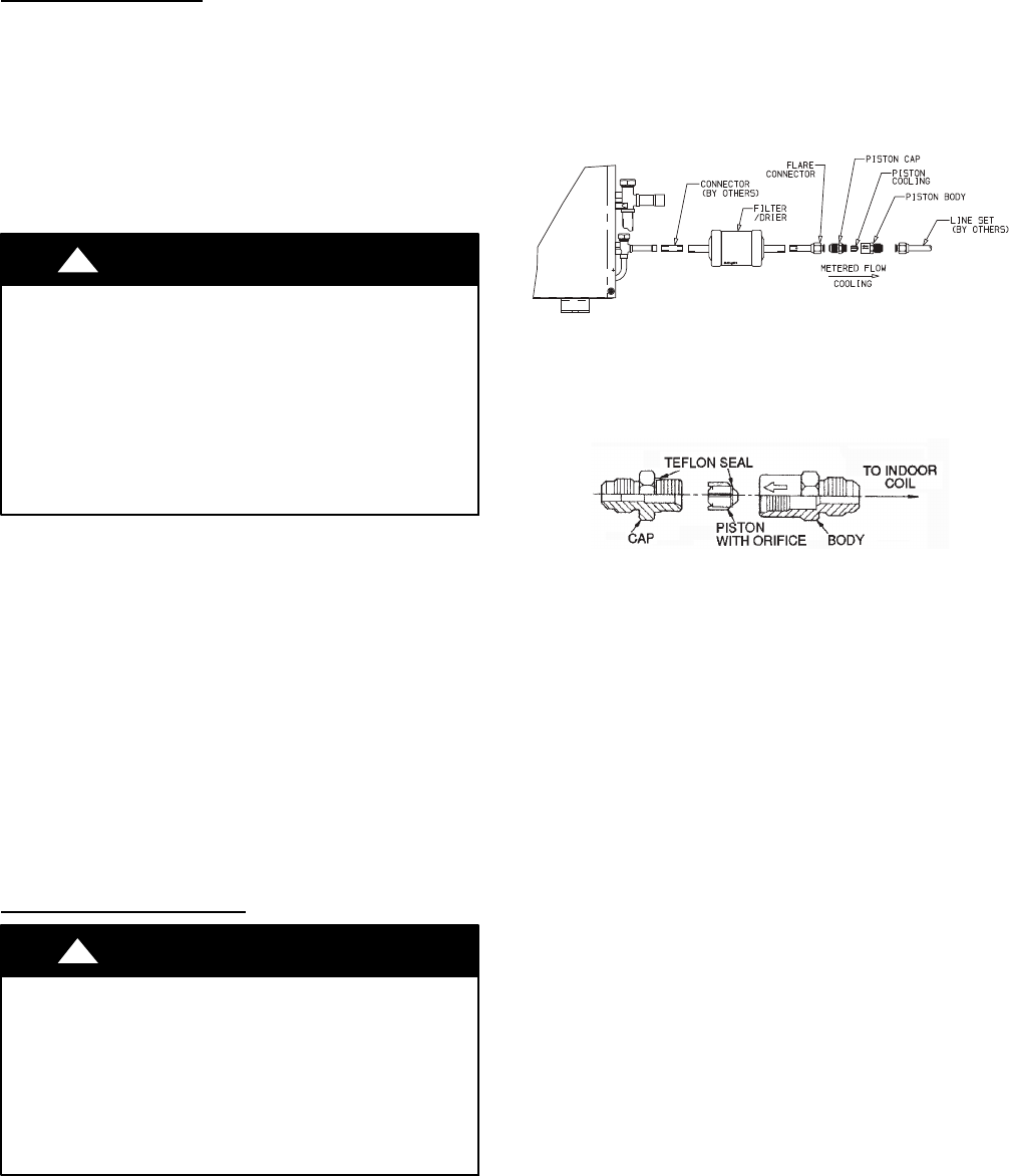
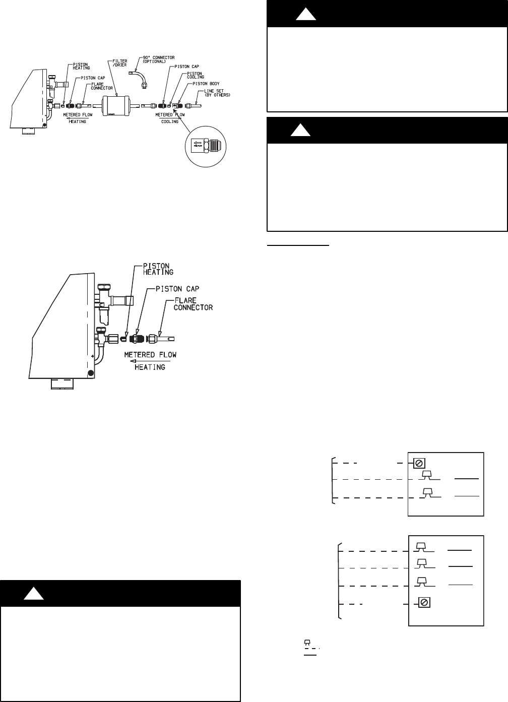
38HDF Units:
1. Assemble the connector tube to the factory supplied filter
drier by:
a. Braze the field supplied connector to the inlet of the
filter drier (see Fig. 17)
b. Braze the factory supplied flare connector to the outlet
end of the filter drier (see Fig.17)
A09499
Fig. 17 -- 38HDF018--036 Connector Tube Assembly
2. Assemble the Accurator body (see Fig. 18) using the correct
factory supplied piston (refer to Table 7) .
NOTE: Arrow on AccuRater body points in free flow direction, away from the
indoor coil.
A09501
Fig. 18 -- AccuRater (bypass type) Metering Device
Components
3. Attach the complete Accurator assembly to the flare connec-
tion end of the filter drier
4. Braze the completed filter drier/Accurator assembly to the
liquid service valve.
5. Connect the field supplied line set to the filter drier/Accura-
tor assembly and the suction valve. A sweat connection is
required at the suction valve and flare connection is required
for the mixed phase line.
6. Insulate any exposed areas between the line set and the li-
quid valve.
9
38QRF Units
1. Assemble the connector tubes to the factory supplied filter
drier by brazing the factory supplied flare connectors to the
inlet and outlet for the filter drier (see Fig. 19)
A09507
Fig. 19 -- 38QRF018--036 Connector Tube Assembly
2. Perform step 2 and 3 from the 38HDF section.
3. Remove the plastic cap from the liquid and suction service
valve on the 38QRF unit and assemble the heating piston
and piston cap supplied with the outdoor unit as shown in
Fig. 20.
A07407
Fig. 20 -- AccuRater (bypass type)
Metering Device Components
NOTE: The Teflon seal on the piston should point towards the
liquid service valve. The size of the factory supplied piston might
have to be adjusted for long line applications (over 80 ft / 24.4 m).
Refer to the Duct Free Long Line Application Guide for additional
information.
4. Attach the flare end of the filter drier assembly to the piston
cap (see Fig. 20).
5. Connect the field supplied line set to the filter drier as-
semblyandtothesuctionvalve.
6. Insulate any exposed areas between filter drier and liquid
valve.
Complete Outdoor Power and Control Wiring
!WARNING
ELECTRICAL SHOCK HAZARD
Failure to follow this warning could result in personal injury or
death.
The unit cabinet must have an uninterrupted or unbroken
ground to minimize personal injury if an electrical fault should
occur. The ground may consist of electrical wire or metal
conduit when installed in accordance with existing electrical
codes.
CAUTION
!
UNIT DAMAGE HAZARD
Failure to follow this caution may result in equipment damage
or improper operation.
Unit failure as a result of operation on improper line voltage or
excessive phase imbalance constitutes abuse and may cause
damage to electrical components. Such operation could void
any applicable Carrier warranty.
!WARNING
ELECTRICAL SHOCK HAZARD
Failure to follow this warning could result in personal injury or
death.
Before performing service or maintenance, be sure indoor unit
main power switch is turned OFF and indoor blower has
stopped.
Lock out and tag switch with a suitable warning label.
Power Wiring
1. Mount outdoor power disconnect. The unit is factory wired
for the voltage shown on the unit nameplate. The fused dis-
connect switch must be provided within sight of the unit,
readily accessible, but out of reach of children. Provisions
for locking the disconnect switch on the OFF (open) posi-
tion is advisable. The disconnect switch must comply with
NEC and local codes. Protect the unit and wiring using only
the recommended fuse/circuit breaker size. See Table 10..
2. Run power wiring from main box to disconnect per NEC
and local codes.
3. Run power wiring from the disconnect switch to outdoor
unit. Use only minimum 60_C copper conductors between
the disconnect switch and the unit for field power connec-
tion.
4. Route the field power wires through the conduit connection
opening in the unit side panel and connect in junction box
as shown in Fig 21. The unit and power wiring must be
grounded.
BLK
BLK
SINGLE-PHASE UNIT
GROUNDING LUG
SINGLE-PHASE
CONN TO
DISCONNECT
PER NEC
BLK
BLU
YEL
GROUNDING LUG
THREE-PHASE
CONN TO
DISCONNECT
PER NEC
THREE-PHASE UNIT
GROUND LEAD
GROUND LEAD
LEGEND
NEC -- National Electrical Code
-- Splice (field)
Field Wiring
Factory Wiring
A08251
Fig. 21 -- Line Power Connections
NOTE: Operating unit on improper line voltage constitutes abuse
and could affect Carrier warranty. Do not install unit in a system
where voltage may fluctuate above or below permissible limits.
10
Control Wiring
The control circuit is 24 volts AC (minimum 40VA) supplied from
the indoor unit.
1. Make sure you have enough control wires to cover the dis-
tance between the indoor and outdoor unit.
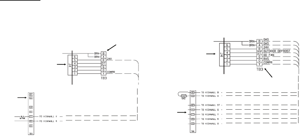
2. Route one end of the control wiring through the opening
provided in the unit side panel and connect to the control
terminal strip using either Fig. 21 for 38HDF units and Fig.
22 for 38QRF units.
Outdoor
Terminal
Board
Indoor
Board
Indoor
Terminal
Board
Outdoor
Terminal
Board
Indoor
Board
Indoor
Terminal
Board
A09508
Fig. 22 -- 38HDF Control Terminal Strip
Outdoor
Terminal
Board
Indoor
Board
Indoor
Terminal
Board
Outdoor
Terminal
Board
Indoor
Board
Indoor
Terminal
Board
A09509
Fig. 23 -- 38QRF Control Terminal Strip
NOTE: Use No. 18 AWG color--coded, insulated (35_C minimum) wire. If the distance between the indoor and outdoor unit is greater than
100 ft. (30.5 m), as measured along the control voltage wires, use No. 16 AWG color--coded wire to avoid excessive voltage drop.
11
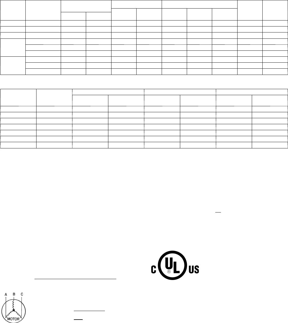
Table 10 – 38HDF / 38QRF Electrical Data
38HDF /
38QRF
UNIT
SIZE
V --- P H --- H z
VOLTAGE RANGE* COMPRESSOR OUTDOOR FAN MOTOR MIN CKT
AMPS
FUSE/
HACR
BKR
AMPS
RLA LRA FLA NEC Hp kW Out
Min Max
018 208/230---1---60 187 253 9.0 48.0 0.80 0.125 0.09 12.1 20
024 208/230---1---60 187 253 12.8 58.3 0.80 0.125 0.09 16.8 25
030 208/230---1---60 187 253 14.1 73.0 1.50 0.25 0.19 18.4 30
035
208/230---1---60 187 253 16.7 79.0 1.50 0.25 0.19 22.3 35
208/230---3---60 187 253 10.4 79.0 1.50 0.25 0.19 14.5 20
4 6 0 --- 3 --- 6 0 414 506 5.8 79.0 0.80 0.25 0.19 8.7 15
036
208/230---1---60 187 253 17.9 112.0 1.45 0.25 0.19 23.8 40
208/230---3---60 187 253 13.2 88.0 1.45 0.25 0.19 18.0 30
4 6 0 --- 3 --- 6 0 414 506 6.0 44.0 0.80 0.25 0.19 8.3 15
Table 11 – 40QNC, QNQ Fan Coil Electrical Data
UNIT SIZE V --- P H --- H z
VOLTAGE RANGE* FAN POWER
Min Max FLA Motor Power
(Watts)
MIN CKT
AMPS
FUSE/CKT
BKR AMPS
40QNC01824 208/230---1---60 187 253 0.38 64 0.48 15
40QNC030 208/230---1---60 187 253 0.38 74 0.48 15
40QNC036 208/230---1---60 187 253 0.44 74 0.55 15
40QNQ018 208/230---1---60 187 253 0.38 64 0.48 15
40QNQ024 208/230---1---60 187 253 0.38 64 0.48 15
40QNQ030 208/230---1---60 187 253 0.38 74 0.48 15
40QNQ036 208/230---1---60 187 253 0.44 74 0.55 15
LEGEND:
FLA --- F u l l L o a d A m p s
LRA --- L o c k e d R o t o r A m p s
NEC --- National Electrical Code
RLA ---RatedLoadAmps(compressor)
* Permissible limits of the voltage range at which the unit will operate
satisfactorily
NOTES:
1. Control circuit is 24---V on all units and requires external power
source. Copper wire must be used from service disconnect to unit.
2. All motors/compressors contain internal overload protection.
3. In compliance with NEC (USA Standard) requirements for multimo-
tor and combination load equipment (refer to NEC Articles 430 and
440), the over current protective device for the unit shall be fuse.
4. Motor RLA values are established in accordance with UL (Under-
writers’ Laboratories) Standard 465 (USA Standard).
5. 38QRF018---030 units are only available in single---phase voltage.
6. Unbalanced 3---Phase Supply Voltage
Never operate a motor where a phase imbalance in supply voltage is
greater than 2%. Use the following formula to determine the percent-
age of voltage imbalance:
= 100 X max voltage deviation from average voltage
average
EXAMPLE: S u p p l y v o l t a g e i s 4 6 0 --- 3 --- 6 0
AB = 452v
BC = 464v
AC = 455v
Average Voltage = 452 + 464 + 455
3
=1371
3
=457
Determine maximum deviation from average voltage:
(AB) 457---452 = 5v
(BC) 464 ---457 = 7v
(AC) 457---455 = 2v
Maximum deviation is 7v.
Determinepercentageofvoltageimbalance
% of voltage imbalance = 100 x 7
57
= 1.53%
This amount of phase imbalance is satisfactory as it is below the maximum
allowable of 2%.
IMPORTANT: Contact your local electric utility company immediately if the
supply voltage phase imbalance is more than 2%.
12
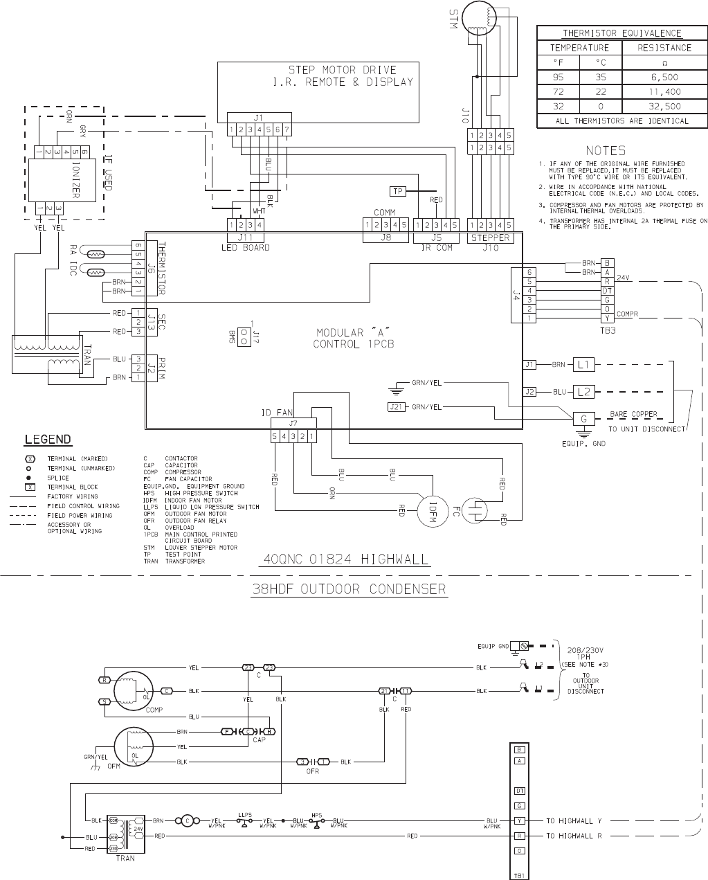
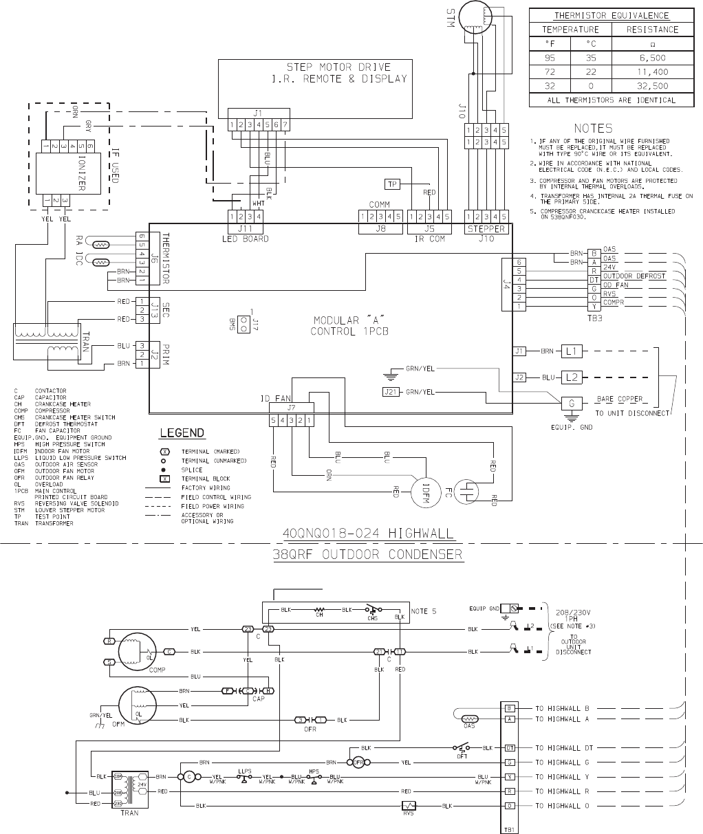
A08367
Fig. 24 -- 40QNC01824 Matched with 38HDF Typical Wiring Schematic
13
Optional on 38QRF018/024 Models
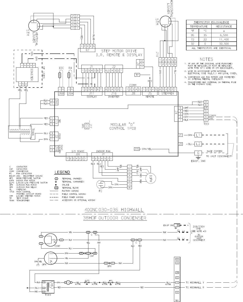
A08368
Fig. 25 -- 40QNQ018,024 Matched with 38QRF Typical Wiring Schematic
14
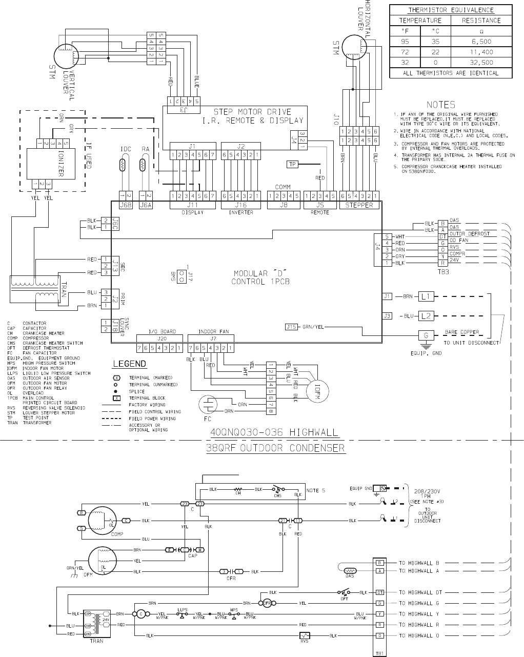
A08369
Fig. 26 -- 40QNC030, 036 Matched with 38HDF Typical Wiring Schematic
15
Optional on 38QRF0036 Models
Standard on 38QRF030
A08370
Fig. 27 -- 40QNQ030, 036 Matched with 38QRF Typical Wiring Schematic
16
Run Power Wiring for Indoor Unit
Be sure field wiring complies with local building codes and NEC,
and unit voltage is within limits shown in Table 11.
Contact local power company for correction of improper line
voltage.
!WARNING
ELECTRICAL SHOCK HAZARD
Failure to follow this warning could result in personal injury
or death.
Before installing, modifying, or servicing system, main
electrical disconnect switch must be in the OFF position.
There may be more than 1 disconnect switch. Lock out and
tag switch with a suitable warning label.
CAUTION
!
UNIT DAMAGE HAZARD
Failure to follow this caution may result in equipment damage
or improper operation.
Unit failure as a result of operation on improper line voltage or
excessive phase imbalance constitutes abuse and may cause
damage to electrical components. Such operation could void
any applicable Carrier warranty.
NOTE: Use copper wire only between disconnect switch(es) and
unit.
NOTE: Install branch circuit disconnect of adequate size to handle
unit starting current per NEC. Locate disconnect within sight of,
and readily accessible from, unit, per section 440--14 of NEC.
Some codes allow indoor unit to share disconnect with outdoor
unit if disconnect can be locked; check local code before installing
in this manner.
The 40QNC/QNQ units require their own power supply.
1. Locate the indoor power supply.
2. Locate and install disconnect switch per NEC and local
codes.
3. Run power supply wiring to disconnect switch.
4. Run power wiring from disconnect switch to wall mount
area.
5. If any accessories are being installed, refer to the individual
accessory instructions for guidance on wire routing at this
time.
Install All Power, Interconnecting Wiring, Piping and
Drain Hose to Indoor Unit .
1. Run control wiring from the outdoor unit through the access
hole in the wall and make sure you have enough wire to
reach the control box of the unit once hung on the mounting
plate.
2. It is a recommended that flare connections is located on the
outside of the wall where the indoor unit is to be mounted.
If an extension pipe is required to facilitate this location,
measure, fabricate and install the extension pipes to the in-
door unit before hanging the unit on the mounting bracket.
3. If piping connections are on the outside wall, pass the pipes
(refrigerant and drain) through the wall sleeve and then
hook the indoor unit body on top of the wall hanging brack-
et. Support the unit away from the bottom using a tool or a
piece of wood.
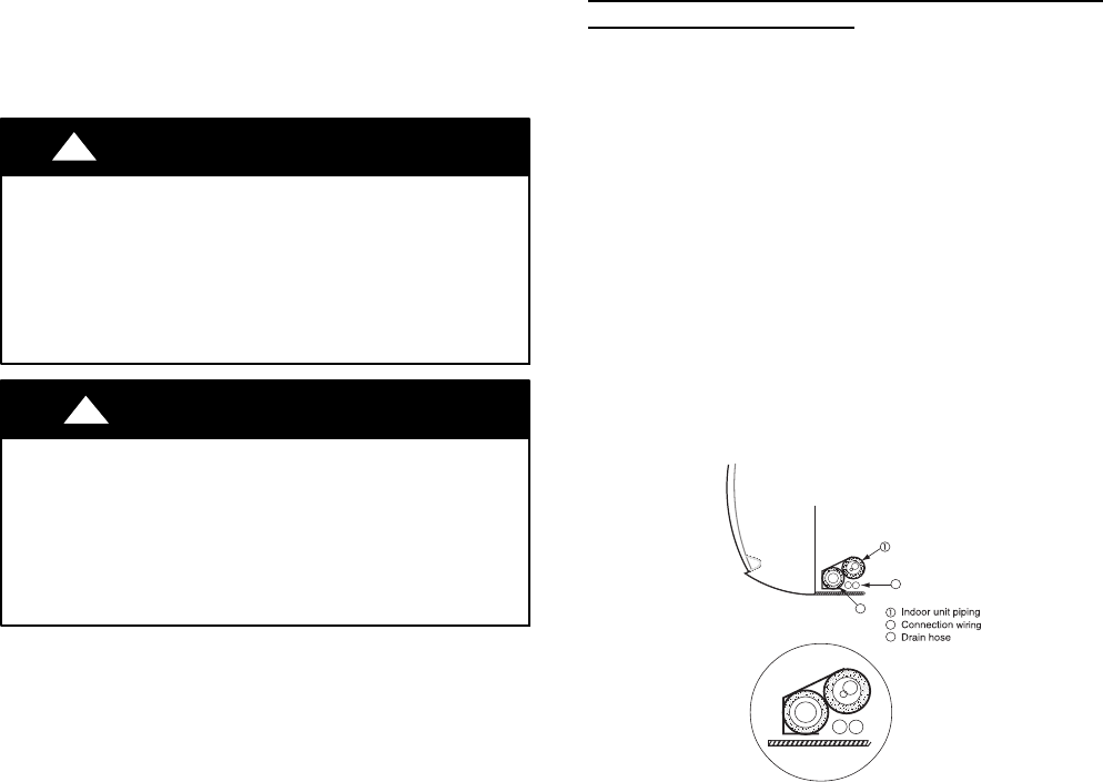
NOTE: Tie together the refrigerant piping, the drain hose, and the
electrical connection wires and ensure that the drain hose is at the
bottom as shown in Fig. 28.
2
3
2
3
A08364
Fig. 28 -- Location of Piping, Hose, and Wiring
4. If required make the flare connections.
5. Route the power and control wiring through the back side
of the unit and to the control box area. If the wired remote
or zone manger accessory are to be used, perform any modi-
fications required at this time. Refer to the Accessory install-
ation instructions).
6. Remove the control box cover and finish all indoor unit
wiring connections as shown on the wiring diagram or in
the accessory installation instructions. Replace the control
box cover.
7. Fix the bottom part of the unit to the wall mounting bracket
and push it carefully until the two bracket hooks fit into the
marked places at the base of the unit until it snaps into
place. See Fig. 29.
17
A
Wall
Hanging
Bracket Hook Hole
Retainer
C lip
Retainer
Clip
B
UNIT SIZE DIMENSION
AB
40QNC01824 13.4 10.6
40QNC030 12.2 12.2
40QNC036 12.2 12.2
40QNQ018 13.4 10.6
40QNQ024 13.4 10.6
40QNQ030 12.2 12.2
40QNQ036 12.2 12.2
A08365
Fig. 29 -- Wall Mounting Details
8. If the refrigerant piping connections are located outside the
wall, tighten the flare connections as shown in Fig. 30. Insu-
late all exposed refrigerant lines and secure to the wall and
fill any void spaces in the hole.
Adjustable wrench or torque wrench
Outdoor end
Indoor end
3
1
2
A07201
Fig. 30 -- Tightening Connections
USER INTERFACE
The indoor unit includes a wireless remote control to operate the
unit (an Owner’s Manual is supplied with the unit). If you have
two units installed in the same space and they need to work
independently, the remote controls and the units need to be
configured as follow:
Unit Configuration
Turn the unit off by pressing the . Press and hold the and
buttons of the remote control for more than 5 seconds. The
display will be cleared and the time segments will display the first
configuration item (rAdr=remote address) and the temperature
segments will display the default value of this configuration item
(Ab=control of both indoor units). Press and to change the
default value to the new value of (a) or (b). Press the button to
transmit the new configuration to the unit. Press the button to
leave the configuration menu.
Remote Control Configuration
Turn the unit off by pressing the button. Press and hold the
and buttons for more than 5 seconds. The display will be
cleared and the time segments will display the first configuration
item (CH=remote address) and the temperature segments will
display the default value of this configuration item (Ab=control of
both indoor units).
Press and to change the default value to the new value of (a)
or (b). Press the button to transmit the new configuration to the
unit. Press the button to leave the configuration menu.
NOTE: When 30 seconds have elapsed and no buttons have been
pressed, the remote control will automatically exit the
configuration menu and resume its normal operation.
A wall mounted control or zone manager can be used to control a
unit or multiple units.
Wired Control
If a wall mounted wired control is required the following steps
should be performed at the same time the indoor control and power
wiring are being connected:
1. Unplug the connector on J5.
2. Remove the wire harness from the wired control box
3. Plug one end of the wire harness into the J5 connector on
the board
4. Route the other end of the wire harness to the back of the
unit along the low voltage wiring
5. Connect the other end of the wire harness to the field sup-
plied wiring between the indoor unit and the wired control
as shown in wired control installation instructions and Fig.
31.
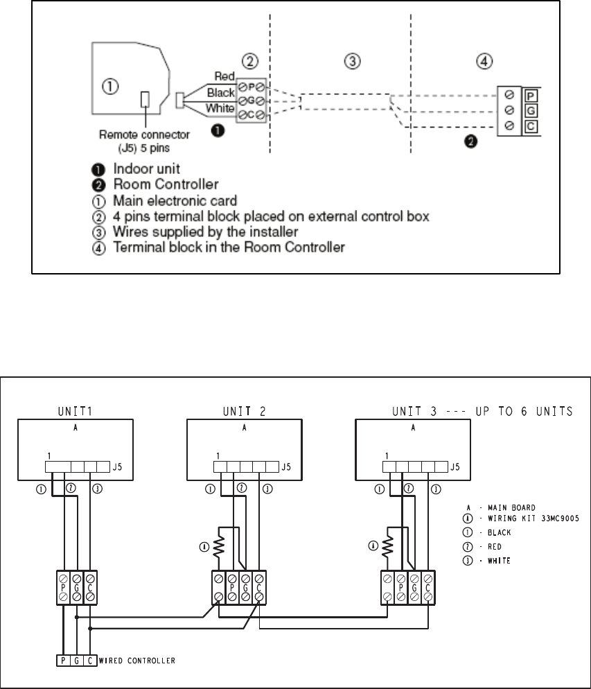
18
A09512
Fig. 31 -- Control Wiring Between Indoor and Outdoor Units
Up to six units can be daisy--chained and controlled from one wired control.
*
* 100 ohm Resistor
A09513
Fig. 32 -- Multiple Unit Control Wiring
19
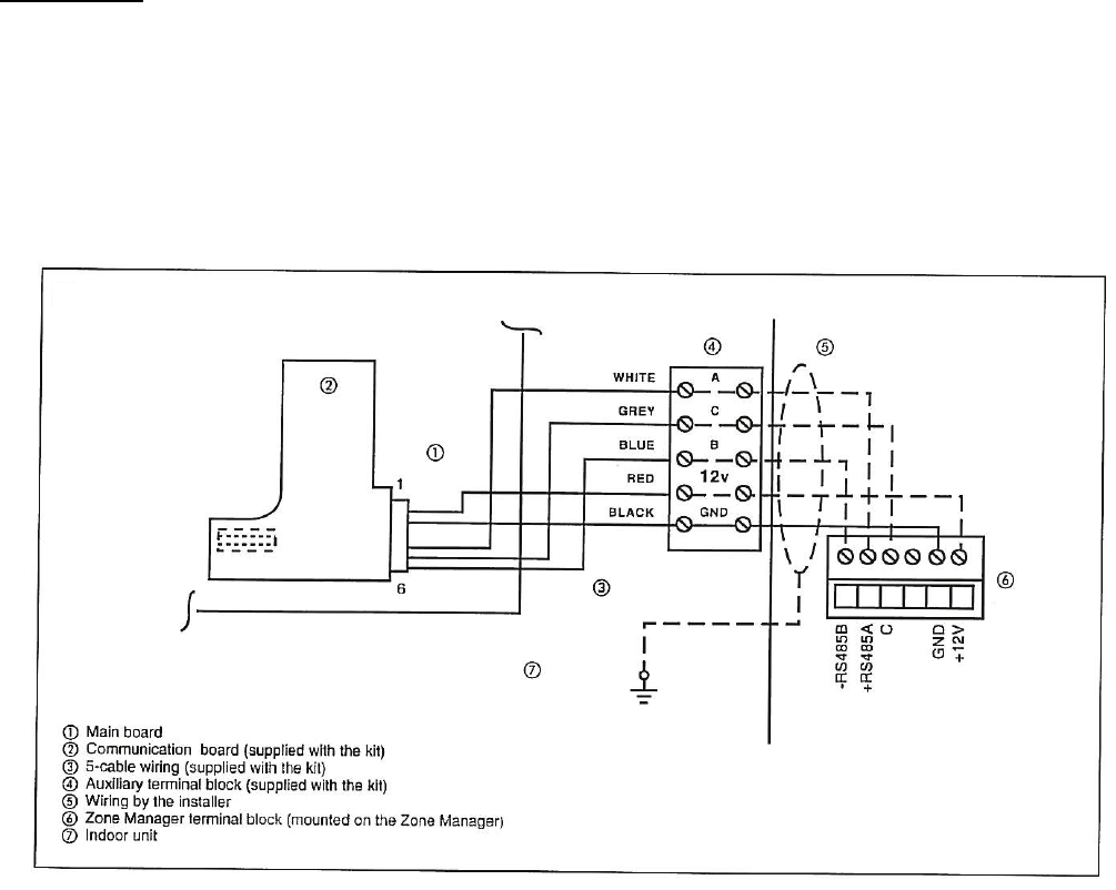
Zone Manager
If a Zone Manager is required, the following steps should be
performed at the same time the indoor control and power wiring
are being connected:
1. Plug the communication board to the J8 as shown in Fig. 33
2. Connect one end of the wire harness supplied with the Zone
Manager to the communication board.
3. Route the other end of the wire harness along the voltage
control to the back of the unit.
4. Connect the other end of the wire harness to the field sup-
plied wiring that will be connected to the zone manager as
shown in Fig. 33. (Shielded cables are required. Refer to
Zone Manager Installation Instructions for further informa-
tion.)
A09514
Fig. 33 -- Wiring for Zone Manager
20
START--UP
Preliminary Checks
1. Check condensate drainage system; on the opposite side of
the drain connection, insert a water bottle up into the fan
coil unit and fill the drain pan. Water must flow steadily; if
not, check the pipe slope or inspect for any pipe restrictions.
2. Make sure all wiring connections are correct and they are
tight.
3. Field electrical power source must agree with unit name
plate rating.
4. Check that all barriers, covers, and panels are in place. En-
sure that the filters and return--air grilles on the indoor unit
have been installed and that the discharge louvers are posi-
tioned correctly.
5. All service valves must be closed.
6. On units with crankcase heaters, ensure belly--band heaters
are tight around the compressor.
Evacuate and Dehydrate the System
CAUTION
!
UNIT DAMAGE HAZARD
Failure to follow this caution may result in equipment damage
or improper operation.
Never use the system compressor as a vacuum pump.
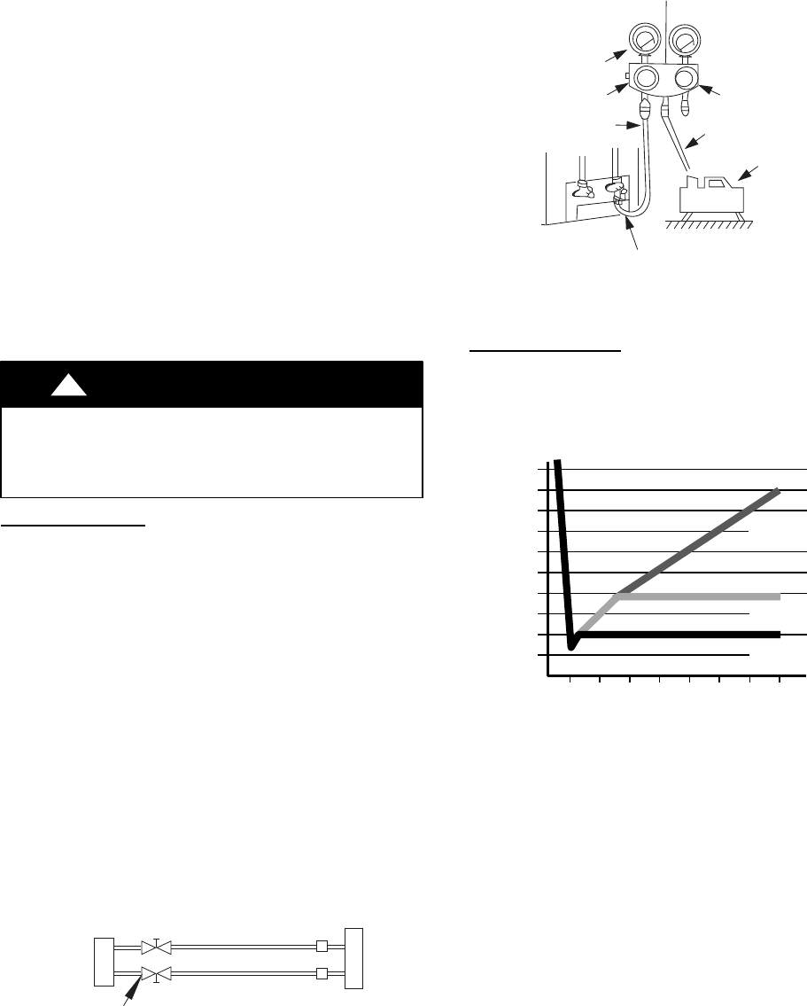
Using Vacuum Pump
1. Completely tighten flare nuts A, B, C, D, connect manifold
gage charge hose to a charge port of the low side service
valve. (See Fig. 34.)
2. Connect charge hose to vacuum pump.
3. Fully open the low side of manifold gage. (See Fig. 35)
4. Start vacuum pump
5. Evacuate using either deep vacuum or triple evacuation
method.
6. After evacuation is complete, fully close the low side of
manifold gage and stop operation of vacuum pump.
7. The factory charge contained in the outdoor unit is good for
up to 25 ft. (8 m) of line length. For refrigerant lines longer
than 25 ft (8 m), add 0.3 oz. per foot of extra piping up to
the maximum allowable length.
8. Disconnect charge hose from charge connection of the low
side service valve.
9. Fully open service valves B and A.
10. Securely tighten caps of service valves.
Outdoor Unit Indoor Uni
t
Refrigerant
Service Valve
Low Side
High Side
A
B
C
D
A07360
Fig. 34 -- Service Valve
Manifold Gage
500 microns
Low side valve
High side valve
Charge hose
Charge hose
Vacuum pump
Low side valve
A07361
Fig. 35 -- Manifold
Deep Vacuum Method
The deep vacuum method requires a vacuum pump capable of
pulling a vacuum of 500 microns and a vacuum gage capable of
accurately measuring this vacuum depth. The deep vacuum method
is the most positive way of assuring a system is free of air and
liquid water. (See Fig. 36)
500
MINUTES
01234567
1000
1500
LEAK IN
SYSTEM
VACUUM TIGHT
TOO WET
TIGHT
DRY SYSTEM
2000
MICRONS
2500
3000
3500
4000
4500
5000
A95424
Fig. 36 -- Deep Vacuum Graph
21
Triple Evacuation Method
The triple evacuation method should only be used when vacuum
pump is only capable of pumping down to 28 in. of mercury
vacuum and system does not contain any liquid water.
Refer to Fig. 37 and proceed as follows:
1. Pump system down to 28 in. of mercury and allow pump to
continue operating for an additional 15 minutes.
2. Close service valves and shut off vacuum pump.
3. Connect a nitrogen cylinder and regulator to system and
open until system pressure is 2 psig.
4. Close service valve and allow system to stand for 1 hr. Dur-
ing this time, dry nitrogen will be able to diffuse throughout
the system absorbing moisture.
5. Repeat this procedure as indicated in Fig. 37. System will
then be free of any contaminants and water vapor.
CHECK FOR TIGHT, DRY SYSTEM
(IF IT HOLDS DEEP VACUUM)
EVACUATE
BREAK VACUUM WITH DRY NITROGEN
WAIT
EVACUATE
RELEASE CHARGE INTO SYSTEM
BREAK VACUUM WITH DRY NITROGEN
EVACUATE
WAIT
A95425
Fig. 37 -- Triple Evacuation Method
To Start the Unit:
1. If the outdoor unit is equipped with a crankcase heater, turn
on the indoor and outdoor disconnect switches to supply
power the system 12 hours before starting the system.
2. Release charge into the system by opening (back--seating)
liquid and suction line service valves.
3. Set the wireless remote control or wired remote control be-
low ambient temperature. Operate the unit for 15 minutes.
4. Refer to Table 6 to determine if additional charge is re-
quired. Also, if you have a long line application, refer to the
Duct Free Long Line Application Guide to determine the
additional charge that is required beyond 25 ft (7.6 m).
5. Calculate the total additional charge required and weigh in.
6. Charge should be added as liquid (not gas) slowly and care-
fully to low side to avoid liquid slugging.
7. Start unit with operation test. In test mode the unit will run
in cooling and heating (on heat pumps) regardless if there is
demand or not.
Set Unit in Test Mode Using Wireless Control
Turn power on to the unit. Insert batteries in remote control. Press
the and the buttons on the remote control for 5 seconds.
The remote control will be cleared and the time segment will
display the Src1=service test mode. Press the button to
transmit the service test signal to the unit. After the test has
completed press the button to leave the test menu.
NOTE: When 30 seconds have elapsed and no buttons have been
pressed, the remote control will automatically exit the test menu
and resume its normal operation.
SetUnitinTestModeUsingWiredControl
There is a hidden service test mode that is initiated through a
combination of button presses when the remote is off. The
following combination must be pressed within a 6 second period:
“DOWN--FAN--UP--FAN--MODE”
Once in service test mode, the service test mode message will be
sent and “Sr” will be displayed in the temperature icons until the
“DOWN” button is pressed.
During Service Test mode, all the icons are off. the only button
that is active is the “DOWN” button.
To cancel Service Test mode, press the “DOWN” button to send a
normal message with “OFF” mode.
Service Test mode automatically times out after 30 minutes and the
remote will operate normally.
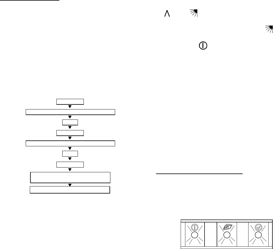
Test Mode Sequence of Operation
Once unit is in TEST MODE, all remote control messages are
ignored except for a message to turn the unit OFF. Buzzer will
beep twice.
When in TEST MODE, the unit will operate as follows:
1. The unit Status (Green) and Timer (Yellow) LEDs will
blink every 2 seconds
GREEN YELLOW
A09594
Fig. 38 -- LED Display
2. Indoor fan will operate according to user – selected speed. If
Autofanisselected,thefanwillruninHighspeed
3. Cooling only system
a. Unit will operate in cool mode with demand
b. Louver will operate according to user -- selected posi-
tion or in cool position if louvers are set to Auto
4. Heat pump system
a. Unit will run in cooling mode with demand for 3
minutes
b. Unit will run in heat pump mode with demand for 2
minutes or until indoor coil temperature is greater than
104_F(40_C). If coil temperature reaches 104_F
(40_C), the unit will run in cool mode until test mode is
exited.
c. Louver will operate according to user -- selected posi-
tion or in cool/heat position if louvers are set to Auto.
5. Following will cancel Test Mode:
a. Unit is turned off by controller
b. Power is cycled during Test Mode
c. 30 minutes elapsed
d. Fail Mode
22
SERVICE
!WARNING
ELECTRICAL SHOCK HAZARD
Failure to follow this warning could result in personal
injury or death.
Before installing, modifying, or servicing system, main
electrical disconnect switch must be in the OFF
position. There may be more than 1 disconnect switch.
Lock out and tag switch with a suitable warning label.
Pump--down Procedure
The system may be pumped down in order to make repairs on the
low side without losing complete refrigerant charge.
1. Attach pressure gage to suction service valve gage port.
2. Front--seat the mixed phase line valve.
CAUTION
!
UNIT DAMAGE HAZARD
Failure to follow this caution may result in equipment damage
or improper operation.
The unit coils hold only the factory--designated amount of
refrigerant. Additional refrigerant may cause units to relieve
pressure through the compressor internal pressure relief valve
(indicated by a sudden rise of suction pressure) before suction
pressure reaches 20 psig. If this occurs, shut off unit
immediately then front--seat the suction valve and remove and
recover excess refrigerant following accepted practices.
3. Start unit and run until suction pressure reaches 5 psig.
4. Shut unit off and front--seat suction valve.
5. Depressurize low side of unit and recover refrigerant fol-
lowing accepted practices.
Filter Drier
Whenever the filter drier is exposed to the atmosphere it must be
replaced. Only use factory specified liquid--line filter driers with
rated working pressures less than 600 psig.
NOTE: Do not install a suction--line filter drier in the mixed phase
line.
Refrigerant Charging
!WARNING
PERSONAL INJURY AND/OR EQUIPMENT
DAMAGE HAZARD
Failure to follow this warning could result in personal
injury and/or equipment damage.
Wear safety glasses and gloves when handling
refrigerant. Do not overcharge system -- this can cause
compressor flooding.
All units are shipped with the refrigerant charge listed on
nameplate.
NOTE: Do not vent or depressurize unit refrigerant to
atmosphere. Remove and recover refrigerant following accepted
practices.
23
TROUBLESHOOTING
See Table 12 and Table 13 for troubleshooting information.
Fault Code
Once a failure occurs with the indoor unit in operation, the green LED on the indoor unit flashes at intervals of 0.5 seconds. The fault code is
deduced from the number of times the green LED flashes, blocking unit operation. Between one flash cycle and the next one, a pause of 3
seconds elapses.
Table 12 – Green LED (Indoor Unit Fault)
CODE DESCRIPTION
3RoomAirSensorFault
4Indoor Unit Coil Sensor Fault
14 OutdoorUnitAirSensorFault
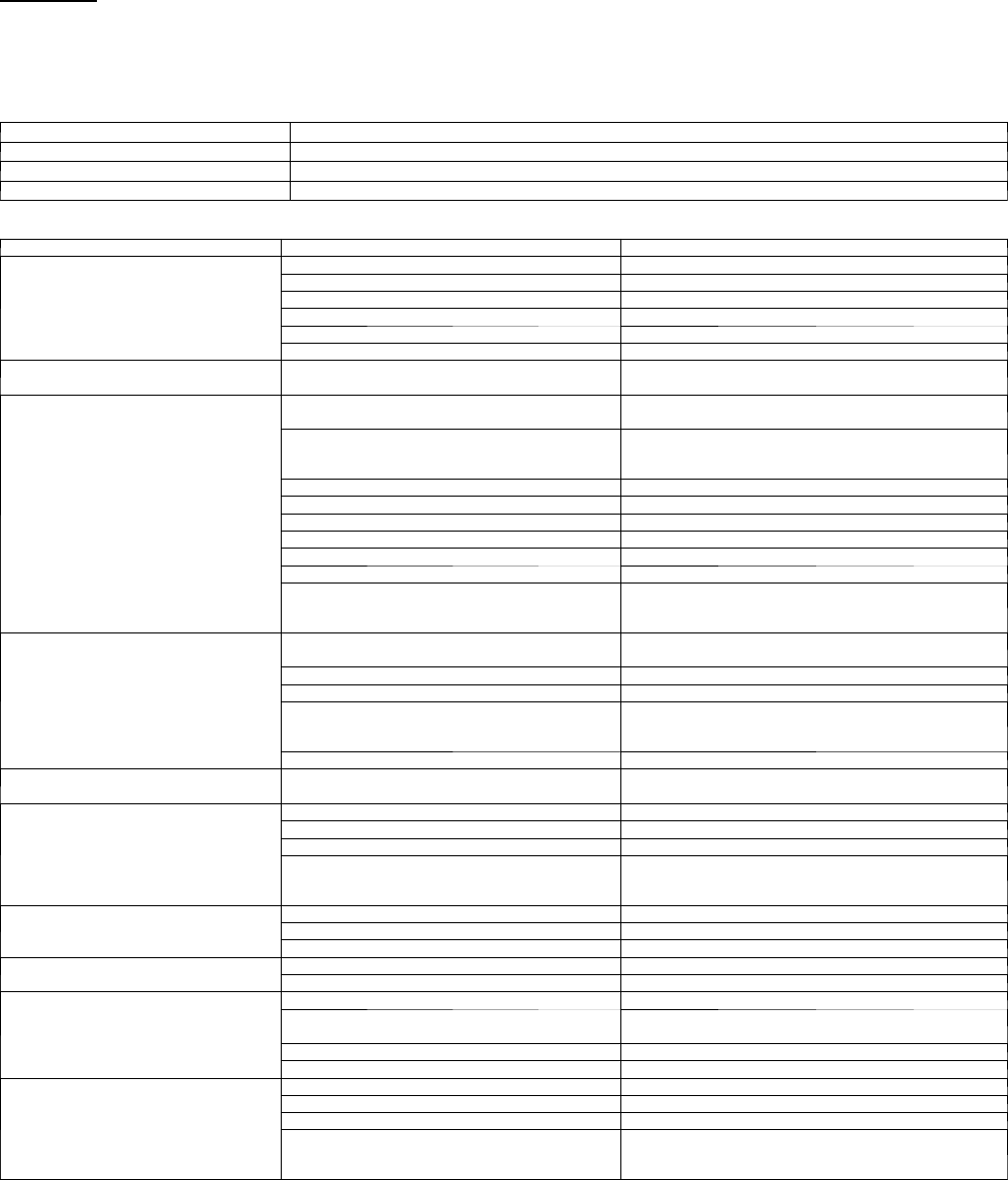
Table 13 – Troubleshooting
PROBLEM POSSIBLE CAUSE SOLUTION
Compressor and Fan of the Outdoor
Unit Will Not Start
Unit not energized Check the main power connection.
Main switch is set to OFF CheckandputittoONposition.
Main switch fuses are blown Replace fuses.
Compressor cycling protection is on Wait for 3 minutes.
Main power voltage is too low Check and set to the correct voltage.
Electrical connections are too loose or are wrong Check and tighten or correct connections.
Compressor Will Not Start, But Out-
door Fan is Operating
Electrical connections of compressor are loose or
wrong Check and tighten or repair compressor.
Compressor Stops Due to Over --- tem-
perature
Compressor burnt out; seized or protection device
on
Check for the cause and replace compressor if neces-
sary.
Wrong refrigerant charge in unit (excessive or low)
or air or other non---condensable gasses in the
circuit
Drain refrigerant, evacuate and recharge. CAUTION: Do
not vent refrigerant to the atmosphere; use refrigerant
recovery equipment.
Main voltage is too high or too low Check voltage setting and adjust if necessary.
Condenser coil obstructed Remove obstruction.
Outdoor fan off Check cause and resume operation or repair.
Wrong indoor unit thermistors Replace thermistors.
Refrigerant circuit clogged Check and remove obstructions.
Reversing valve faulty on heat pump models Replace reversing valve.
Expansion device clogged or covered with ice
Drain refrigerant, evacuate and recharge. CAUTION: Do
not vent refrigerant to the atmosphere; use refrigerant
recovery equipment.
Compressor Runs Continuously
Unit selected is too small for application require-
ments
Contact a qualified service technician for a system evalu-
ation.
Indoor temperature setting too low or too high Check temperature setting.
Outdoor unit fan faulty Replace outdoor fan.
Air or other non---condensable gasses in the cir-
cuit
Drain refrigerant, evacuate and recharge. CAUTION: Do
not vent refrigerant to the atmosphere; use refrigerant
recovery equipment.
Obstructions at air intake or dirty indoor unit filters Remove obstruction and/or clean filter.
F r e q u e n t I c e --- B u i l d --- U p o n O u t d o o r
Coil Outdoor fan is stopped Check cause and repair.
Discharge Pressure Too High
Outdoor coil dirty or obstructed Clean or remove obstructions.
Condenser fan faulty Replace condenser fan.
Indoor temperature setting too low or too high Check temperature setting.
Air or other non---condensable gasses in the cir-
cuit
Drain refrigerant, evacuate and recharge. CAUTION: Do
not vent refrigerant to the atmosphere; use refrigerant
recovery equipment.
Discharge Pressure Too Low
Indoor temperature setting too high or too low Check temperature setting.
Outdoor coil dirty or obstructed Clean or remove obstructions.
Indoor unit air filter dirty Clean filter.
Suction Pressure Too High Indoor temperature setting too high or too low Check temperature setting.
Reversing valve faulty or internal leak Replace reversing valve.
Suction Pressure Too Low
Indoor temperature setting too high or too low Check temperature setting.
Evaporator coil covered with ice Air circulation on the evaporator not sufficient; check and
repair.
Expansion device or suction line clogged Check and repair.
Outdoor fan does not stop during defrost periods Check electrical parts.
Outdoor Fan Cycling Due to Over---
Te m p e r a t u r e P r o t e c t i o n
Electrical connection loose Check connections.
Fan motor burn out Replace.
Fan bearing seized Check and repair.
Expansion device clogged or covered with ice
Drain refrigerant, evacuate and replace.
CAUTION: Do not vent refrigerant to the atmosphere; use
refrigerant recovery equipment.

24
Copyright 2009 Carrier Corp. S7310 W. Morris St. SIndianapolis, IN 46231 Printed in U.S.A. Edition Date: 09/09
Manufacturer reserves the right to change, at any time, specifications and designs without notice and without obligations.
C a t a l o g N o : 4 0 Q N C --- Q --- 9 S I
Replaces: 40QN--- 8SI
