Carrier 42C Users Manual 42 3si
42S to the manual 1e3d6bbe-5527-4711-9a17-5af3fed6f468
2015-01-24
: Carrier Carrier-42C-Users-Manual-310412 carrier-42c-users-manual-310412 carrier pdf
Open the PDF directly: View PDF ![]() .
.
Page Count: 72
Manufacturer reserves the right to discontinue, or change at any time, specifications or designs without notice and without incurring obligations.
Catalog No. 04-53420004-01 Printed in U.S.A. Form 42-3SI Pg 1 12-09 Replaces: 42-2SI
Installation, Start-Up and Service
Instructions
CONTENTS
Page
SAFETY CONSIDERATIONS . . . . . . . . . . . . . . . . . . . . . . 1
INTRODUCTION . . . . . . . . . . . . . . . . . . . . . . . . . . . . . . . . . . 1
PHYSICAL DATA . . . . . . . . . . . . . . . . . . . . . . . . . . . . . . . 1-3
PRE-INSTALLATION. . . . . . . . . . . . . . . . . . . . . . . . . . . 3-39
Unpack and Inspect Units . . . . . . . . . . . . . . . . . . . . . . . . 3
Protect Units From Damage . . . . . . . . . . . . . . . . . . . . . . 3
Prepare Jobsite for Unit Installation. . . . . . . . . . . . . . 3
Identify and Prepare Units. . . . . . . . . . . . . . . . . . . . . . . . 3
INSTALLATION . . . . . . . . . . . . . . . . . . . . . . . . . . . . . . . 40-67
Step 1 — Place Units in Position . . . . . . . . . . . . . . . . 40
• 42C UNITS
• 42V UNITS
• 42D UNITS
• 42S UNITS
Step 2 — Make Piping Connections . . . . . . . . . . . . . 42
• VALVE PACKAGES
• 42C,D,V DRAIN CONNECTIONS
• 42C,D,V WATER SUPPLY/RETURN
CONNECTIONS
• 42C,D,V STEAM CONNECTIONS
• 42C,D,V DIRECT EXPANSION (DX) REFRIGERANT
PIPING
• TEST AND INSULATE
Step 3 — Make Electrical Connections . . . . . . . . . . 55
• STANDARD WIRING PACKAGES
Step 4 — Make Duct Connections . . . . . . . . . . . . . . . 66
Step 5 — Frame and Finish Unit. . . . . . . . . . . . . . . . . 66
Step 6 — Cut out Openings for Grilles and
Thermostats . . . . . . . . . . . . . . . . . . . . . . . . . . . . . . . . . . 67
Step 7 — Make Final Preparations. . . . . . . . . . . . . . . 67
START-UP . . . . . . . . . . . . . . . . . . . . . . . . . . . . . . . . . . . . . . . 67
SERVICE . . . . . . . . . . . . . . . . . . . . . . . . . . . . . . . . . . . . . .67,68
Excessive Condensation on Unit. . . . . . . . . . . . . . . . 67
To Clean Coil. . . . . . . . . . . . . . . . . . . . . . . . . . . . . . . . . . . . 67
Coil Air Vent (Manual or Automatic) . . . . . . . . . . . . . 67
Check Drain . . . . . . . . . . . . . . . . . . . . . . . . . . . . . . . . . . . . . 67
Fan Motor Bearings . . . . . . . . . . . . . . . . . . . . . . . . . . . . . 67
Clean Fan Wheel . . . . . . . . . . . . . . . . . . . . . . . . . . . . . . . . 68
Clean Electric Heater. . . . . . . . . . . . . . . . . . . . . . . . . . . . 68
Clean or Replace Air Filters . . . . . . . . . . . . . . . . . . . . . 68
Warranty . . . . . . . . . . . . . . . . . . . . . . . . . . . . . . . . . . . . . . . . 68
START-UP CHECKLIST FOR 42C,D,S,V SERIES
FAN COIL AIR CONDITIONERS. . . . . . . . CL-1, CL-2
SAFETY CONSIDERATIONS
Installation of this unit can be hazardous due to electrical com-
ponents and equipment location (such as a ceiling or elevated
structure). Only trained, qualified installers and service
mechanics should install and service this equipment.
When installing this unit, observe precautions in the literature,
labels attached to the equipment, and any other safety precau-
tions that apply.
• Follow all safety codes.
• Wear safety glasses and work gloves.
• Use care in handling and installing this accessory.
INTRODUCTION
This document contains general installation instructions for
the 42C,D,S,V unit fan coils. Refer to the unit-wiring diagram
installed on the blower housing or specific manufacturer litera-
ture for any other type of factory-mounted controls.
See drawings for unit configurations, dimensions, clearances,
and pipe connections. Refer to unit wiring label for all electrical
connections; follow NEC (National Electrical Code) and local
codes.
PHYSICAL DATA
Component weight data, shipping weights, and filter data of
the 42C,D,S,V units are provided in Tables 1-4.
WARNING
ELECTRIC SHOCK HAZARD To avoid the possibility of
electrical shock, open and tag all service switches before
installing this equipment.
42C,D,S,V Series
Fan Coil Air Conditioners
2
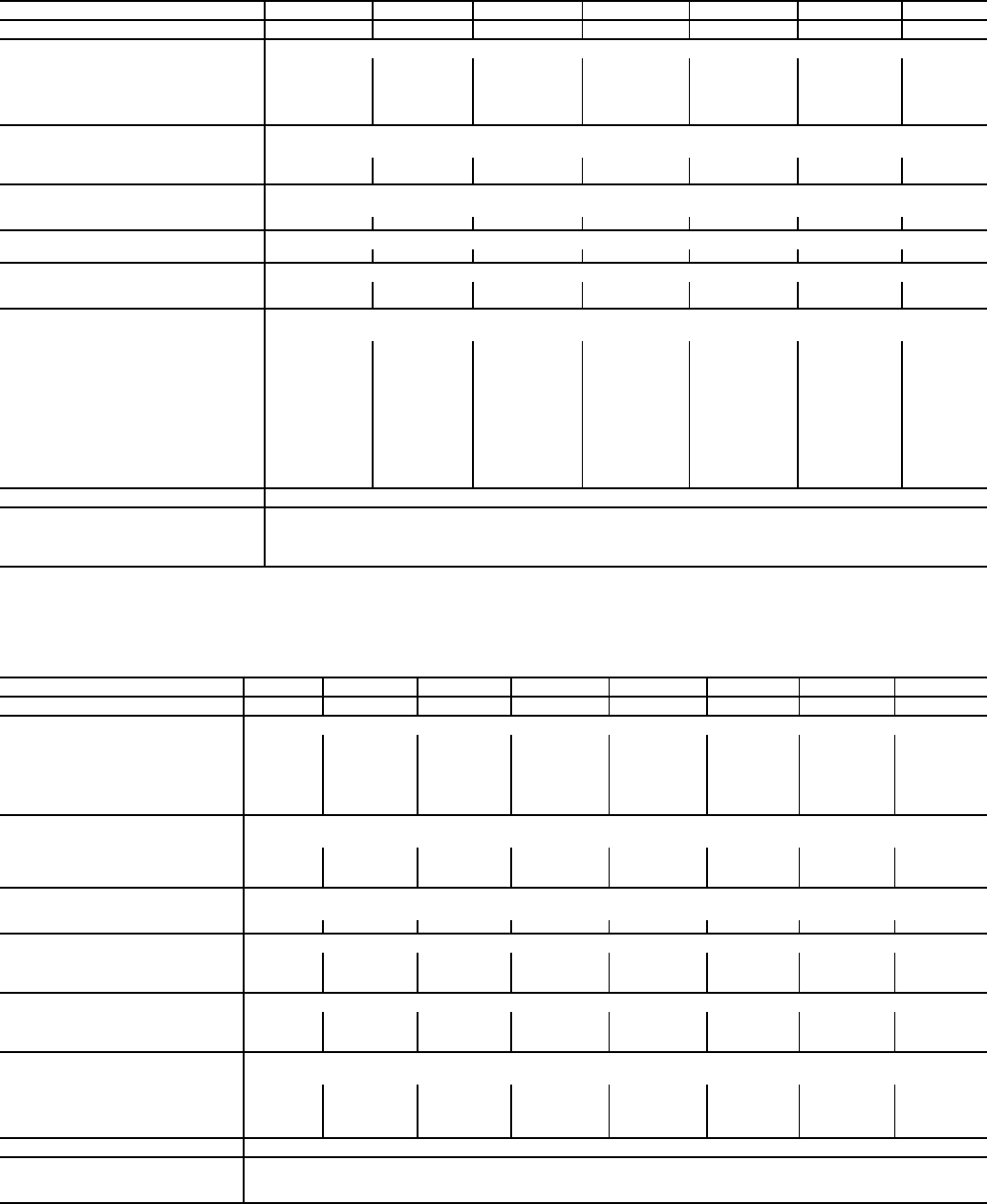
Table 1 — Physical Data — 42C Series Units
*Calculate operating weight of unit: shipping weight + coil water weight x
number of coil rows.
†42CF applies to sizes 04 to 10.
**Filter size for return-air grille location.
††Filter size if located in return-air plenum.
***With electric heater and bottom return, the 42CF unit filter width increases
from 123/4 to 163/4.
Table 2 — Physical Data — 42V Series Units
*Calculate operating weight of unit: shipping weight + coil water weight x
number of coil rows.
†Available in sizes 02-06.
UNIT SIZE 42C 02 03 04 06 08 10 12
NOMINAL AIRFLOW (cfm) 200 300 400 600 800 1000 1200
SHIPPING WEIGHT (lb)*
42CA 36 39 49 59 64 95 107
42CE 55 60 70 82 95 135 154
42CF — — 84 97 110 163 —
42CG 98 118 126 168 176 215 245
42CK 115 120 135 150 155 227 241
COIL WATER WEIGHT
(Approx lb per row of coil)
42CA, CE, CG, CK 0.7 0.8 1.0 1.4 1.7 2.3 2.7
42CF — — 1.02 1.42 1.71 2.32 —
COILS
FPI 10 fins/inch
Coil Face Area (sq ft)† 0.8 1.1 1.4 1.9 2.3 3.2 3.7
MOTOR (qty)
42C Series 111 1 1 22
BLOWER (qty)
42CA, CE, CG, CK 112 2 2 44
42CF —— 2 2 2 4—
FILTERS
Nominal Size (in.) (1-in. thick)
42CA** 10 x 24 10 x 28 10 x 32 10 x 42 10 x 42 10 x 54 10 x 64
42CE†† 10 x 18 10 x 22 10 x 28 10 x 33 10 x 40 10 x 54 10 x 62
42CF††*** ——12
3/4 x 28 123/4 x 33 123/4 x 40 123/4 x 54 —
42CG
Bottom Return 10 x 231/210 x 28 10 x 321/210 x 37 10 x 41 10 x 541/210 x 63
Rear Return 8 x 231/28 x 28 8 x 321/28 x 37 8 x 41 8 x 541/28 x 63
42CK
Bottom Return 10 x 28 10 x 28 10 x 33 10 x 45 10 x 45 10 x 62 10 x 62
Rear Return 7 x 21 7 x 21 7 x 27 7 x 38 7 x 38 7 x 52 7 x 52
Rear Return with Duct Collar 6 x 183/46 x 183/46 x 243/46 x 353/46 x 353/46 x 493/4 6 x 493/4
Qty 111 1 1 11
SUPPLY DUCT COLLAR 1-in.
PIPING CONNECTIONS (Sweat) (in.)
Coil Outlet and Inlet 5/8 OD
Drain Connection 7/8 OD
Tell-Tale Drain 5/8 OD
UNIT SIZE 42V 01 02 03 04 06 08 10 12
NOMINAL AIRFLOW (cfm) 150 200 300 400 600 800 1000 1200
SHIPPING WEIGHT (lb)*
42VA — 65 80 90 112 115 140 170
42VB — 89 95 116 134 137 169 192
42VC — 50 60 72 110 — — —
42VE — 72 100 108 154 — — —
42VF — 92 98 122 141 144 178 205
42VG 40 — 74 — — — — —
COIL WATER WEIGHT
(Approx lb per row of coil)
42VA, VB, VC†, VF — 0.7 0.8 1.0 1.4 1.7 2.3 2.7
42VE — 0.9 1.2 1.6 2.3 — — —
42VG 0.4 — 1.0 — — — — —
COILS
FPI 12 fins/inch
Coil Face Area (sq ft) 0.8 0.8 1.1 1.4 1.9 2.3 3.2 3.7
MOTOR (qty)
42VA, VB, VF —11 1 1 122
42VC, VE —1 1 1 2 — — —
42VG 1— 2 — — — — —
BLOWER (qty)
42VA, VB, VF —11 2 2 244
42VC, VE —2 2 2 4 — — —
42VG 1— 2 — — — — —
FILTERS
Nominal Size (in.) (1-in. thick)
42VA, VB, VF —7
3/4 x 213/473/4 x 253/473/4 x 313/473/4 x 413/473/4 x 433/473/4 x 573/473/4 x 653/4
42VC, VE —7 x 21
3/47 x 263/47 x 343/47 x 483/4———
42VG 10 x 141/2— 10 x 28 — — — — —
Qty 111 1 1111
SUPPLY DUCT COLLAR 1-in.
PIPING CONNECTIONS (Sweat) (in.)
Coil Outlet and Inlet 5/8 OD
Drain Connection 3/4 MPT
3
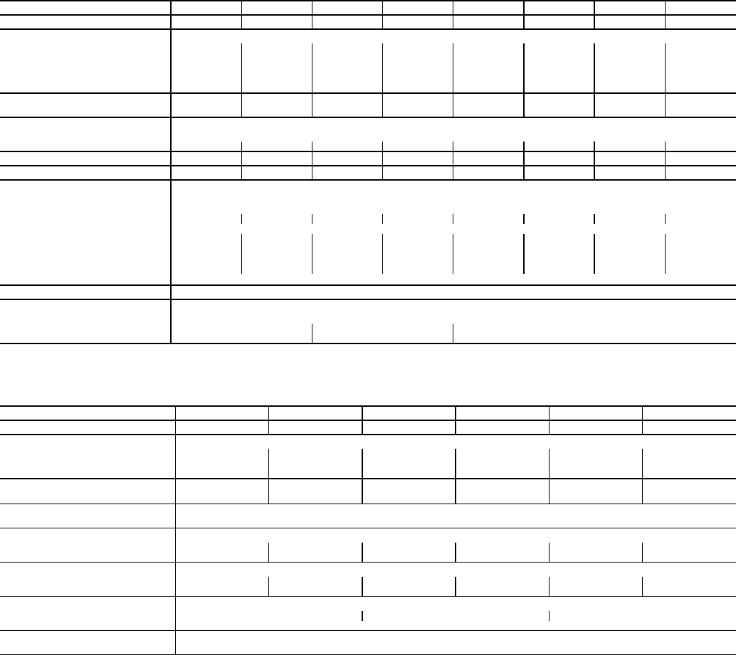
Table 3 — Physical Data — 42D Series Units
*Calculate Operating Weight of unit: Shipping Weight + Coil Water Weight x Number of Coil Rows.
Table 4 — Physical Data — 42S Series Units
*Calculate Operating Weight of Unit: Shipping Weight + Coil Water Weight x Number of Coil Rows.
†42SJ units require two filters.
PRE-INSTALLATION
Unpack and Inspect Units — Remove shipping wraps
from all units. Check the shipment against shipping order.
Make sure that furnished only items, such as thermostat,
grilles, etc., are accounted for, whether packaged separately or
shipped at a later date. If shipment is damaged or incomplete,
file claim with transportation company and advise Carrier im-
mediately.
Protect Units from Damage — The equipment must
always be properly supported. Temporary supports used during
installation or service must be adequate to hold the equipment
securely. Equipment should always be stored in the proper ori-
entation as marked on the carton. To maintain warranty, protect
units against adverse weather, theft, vandalism, and debris on
jobsite. Equipment covered in this manual is not suitable for
outdoor installations. Do not allow foreign material to fall into
drain pan. Prevent dust and debris from being deposited on mo-
tor and fan wheels. Manufacturer's warranty is void if foreign
material is allowed to be deposited on the motor or blower
wheels of any unit.
Prepare Jobsite for Unit Installation — To save
time and to reduce the possibility of costly errors, set up a com-
plete sample installation in a typical room at jobsite. Check all
critical dimensions such as pipe, wire, and duct connection
requirements. Refer to job drawings and product dimension
drawings as required (see Fig. 1-36). Instruct all trades in their
part of the installation.
Identify and Prepare Units — Be sure power require-
ments match available power source. Refer to unit nameplate
and wiring diagram.
1. Check all tags on unit to determine if shipping screws are
to be removed. Remove screws as directed.
2. Rotate the fan wheel by hand to ensure that the fan is
unrestricted and can rotate freely. Check for shipping
damage and fan obstructions.
UNIT SIZE 42D 0608101214161820
NOMINAL AIRFLOW (cfm) 600 800 1000 1200 1400 1600 1800 2000
SHIPPING WEIGHT (lb)*
42DA 64 79 93 110 119 129 137 155
42DC 94 107 150 169 174 178 195 220
42DD 150 163 176 195 220 235 240 247
42DE 135 155 165 184 199 215 232 243
42DF 157 167 177 199 215 229 249 258
COIL WATER WEIGHT
(Approx lb per row of coil) 1.31.61.92.32.73.03.43.7
COILS
FPI 10 fins/inch
Coil Face Area (sq ft) 1.62.12.53.03.54.14.65.0
MOTOR (qty) 11122222
BLOWER (qty) 11122222
FILTERS
Nominal Size (in.) (1-in. thick)
42DA NA
42DC 14 x 21 14 x 26 14 x 30 14 x 35 14 x 40 14 x 45 14 x 50 14 x 54
42DD
(Front Return) 123/4 x 21 123/4 x 26 123/4 x 30 123/4 x 35 123/4 x 40 123/4 x 45 123/4 x 50 123/4 x 54
(Bottom Return) 123/4 x 21 123/4 x 25 123/4 x 29 123/4 x 34 123/4 x 39 123/4 x 44 123/4 x 49 123/4 x 53
42DE 14 x 143/414 x 193/414 x 233/414 x 283/414 x 333/414 x 383/414 x 433/414 x 473/4
42DF 14 x 14 14 x 20 14 x 24 14 x 28 14 x 34 14 x 38 14 x 44 14 x 48
Qty 1
SUPPLY DUCT COLLAR 1-in.
PIPING CONNECTIONS
(Sweat - 4-Row)
Inlet (in. OD) 5/87/811/8
Outlet (in. OD) 5/87/811/8
UNIT SIZE 42S 03 04 06 08 10 12
NOMINAL AIRFLOW (cfm) 300 400 600 800 1000 1200
SHIPPING WEIGHT (lb)*
42SG,SU 180 225 240 260 280 305
42SH 202 247 262 286 311 336
42SJ 360 450 480 520 560 610
COIL WATER WEIGHT
(Approx lb per row of coil) 1.6 1.6 2.3 2.3 3.1 3.1
COILS
FPI 14 fins/inch
MOTOR (qty)
42SG,SH,SU 111111
42SJ 222222
BLOWER (qty)
42SG,SH,SU 111111
42SJ 222222
FILTERS
Nominal Size (in.) (1-in. thick) 121/2 x 241/4161/4 x 263/4201/2 x 291/4
Qty 1†
PIPING CONNECTIONS
Inlet (in. OD) 1/2
4
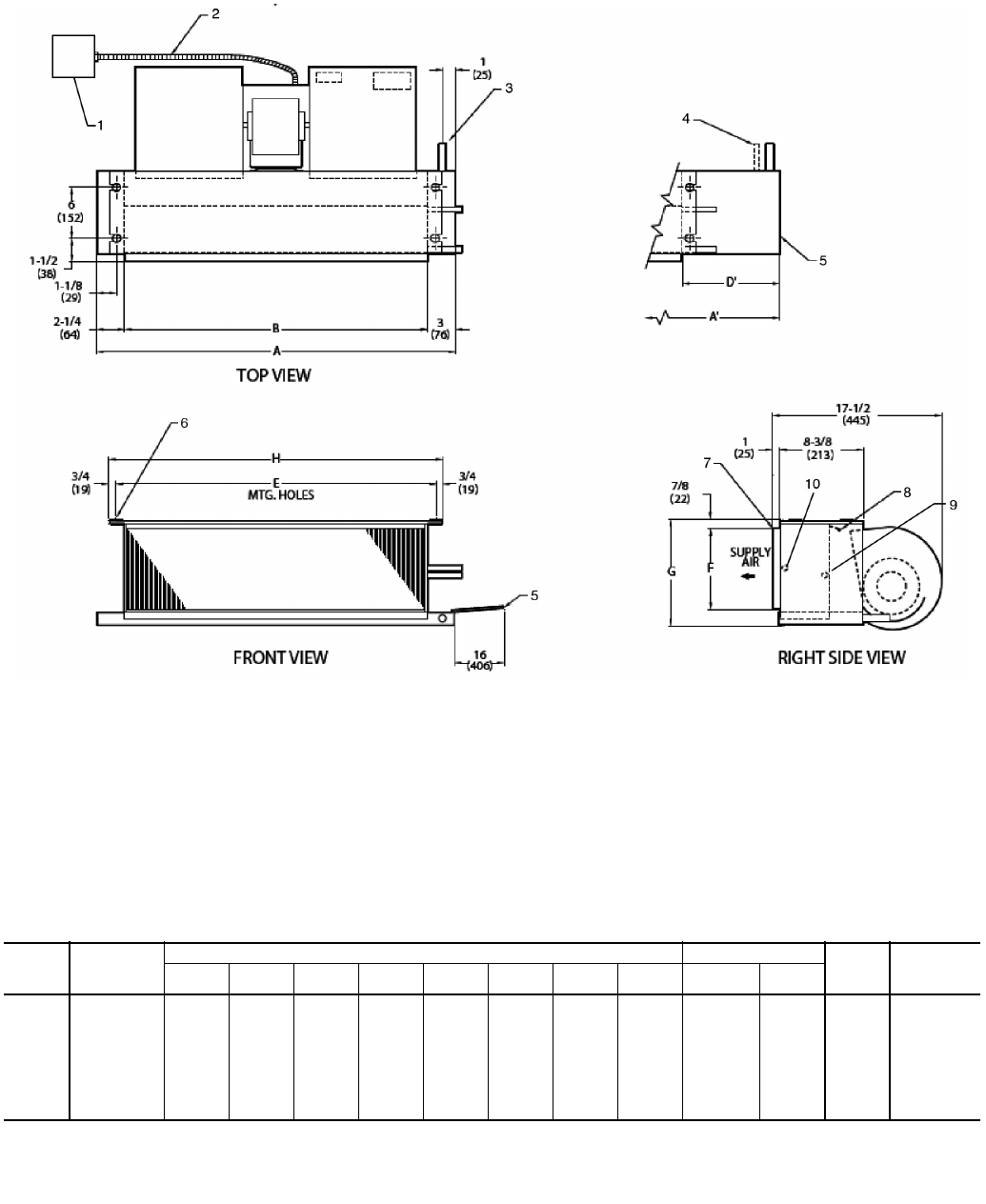
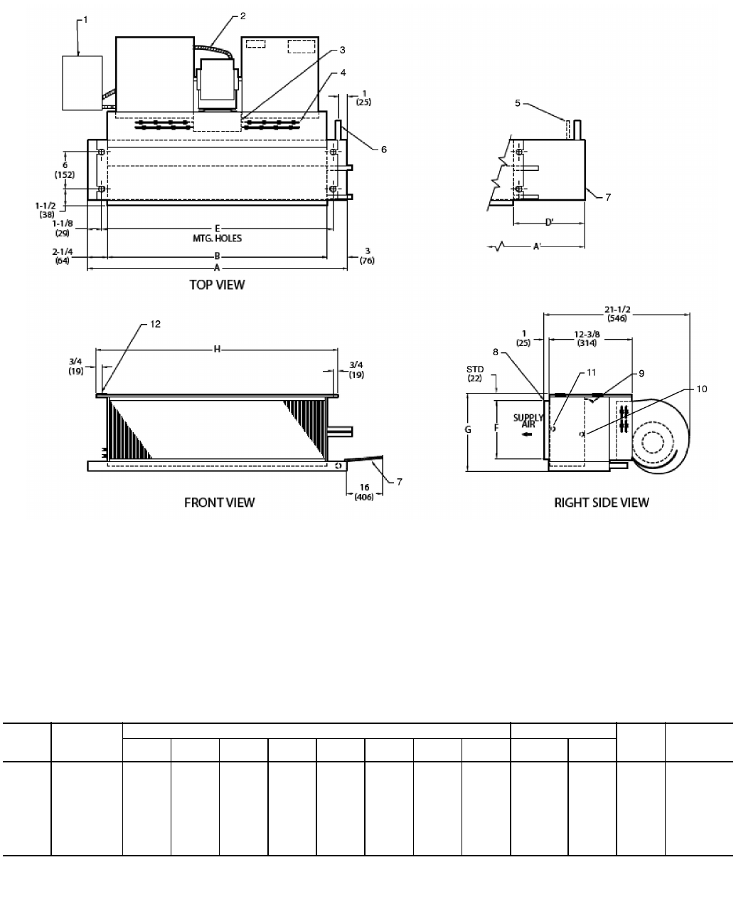
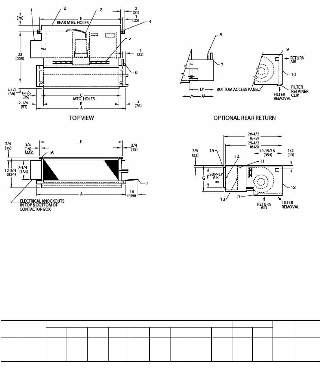
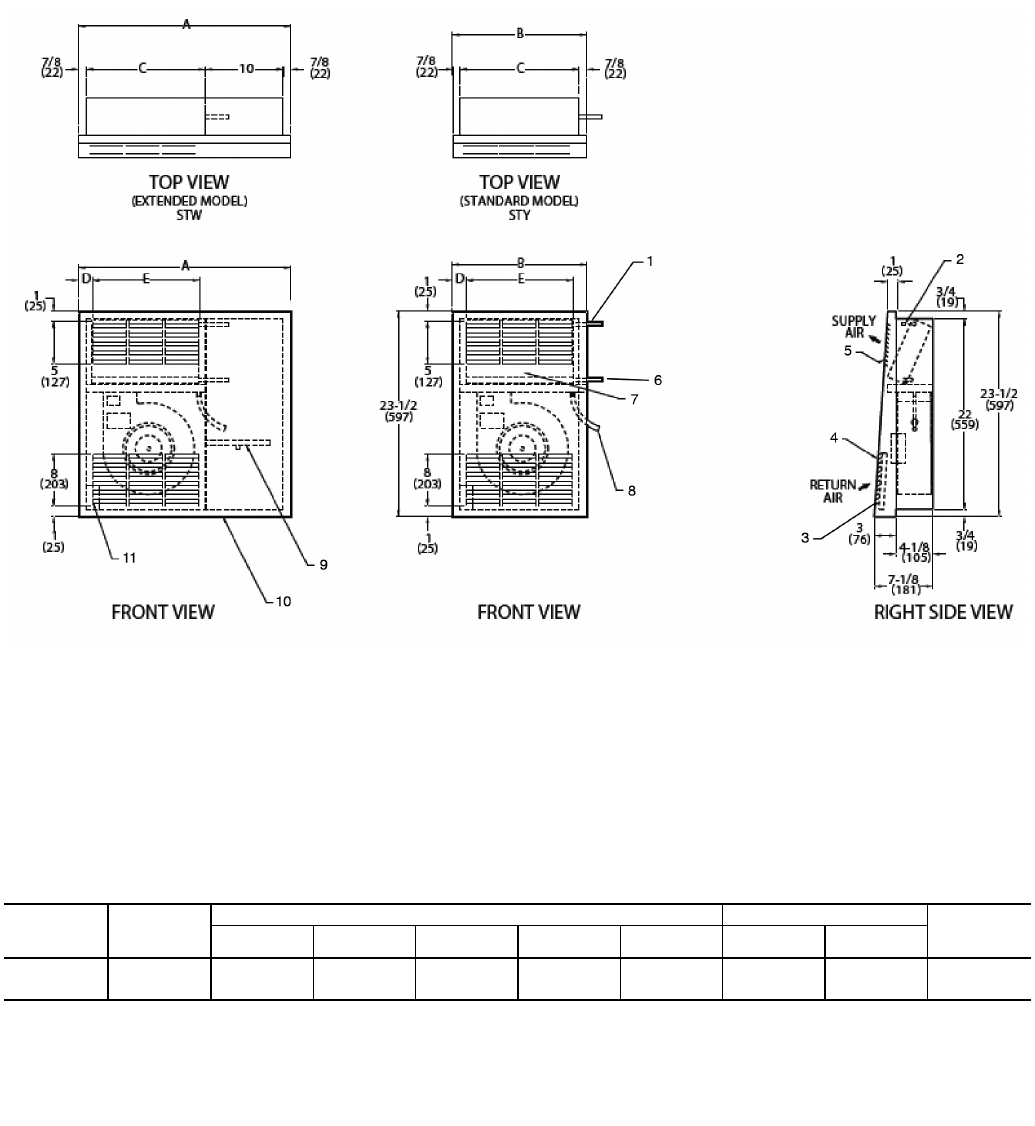
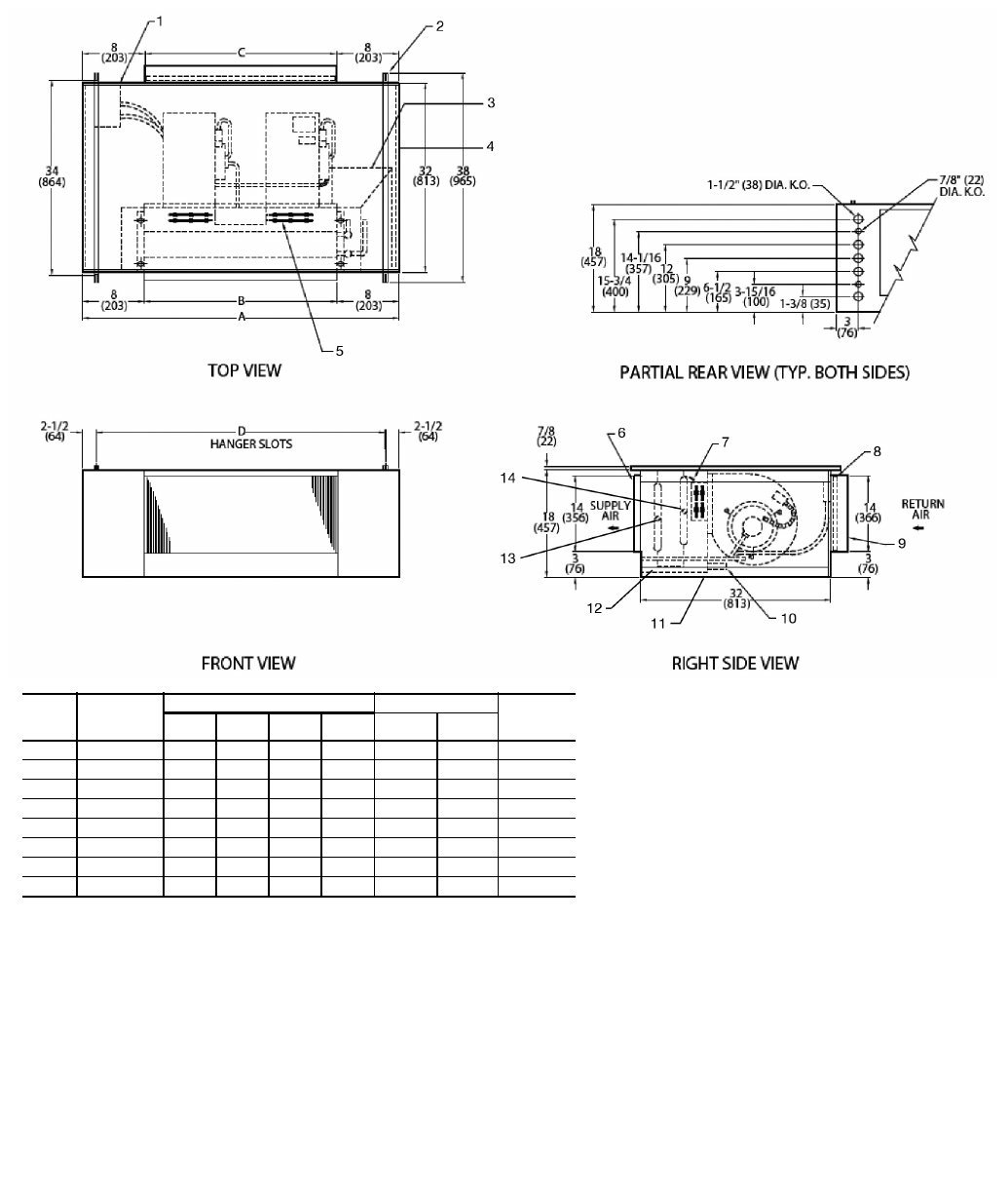
LEGEND
1—Junction Box (remote mount)
2—Flexible Metal Conduit
3—Drain Conn, 7/8-in. OD
4 — Tell-Tale Drain Conn, 5/8-in. OD (optional)
5—Drip Lip (optional)
6—Hanger Slots (4), Rubber Grommet
has 3/8-in. Diameter Hole
7—Supply Duct Collar, 1-in.
8—Air Vent, 1/8-in. MPT
9—Return Conn, 5/8-in. OD
10 — Supply Conn, 5/8-in. OD
*Unit weights are based on dry coils and minimum rows. Weights exclude packaging, valves, and other components.
UNIT
SIZE
NOM
AIRFLOW
(Cfm)
DIMENSIONS (in.) QTY/UNIT FACE
AREA
(sq ft)
UNIT
WEIGHT*
(lb)
AA’BD’E F GH
Blower Motor
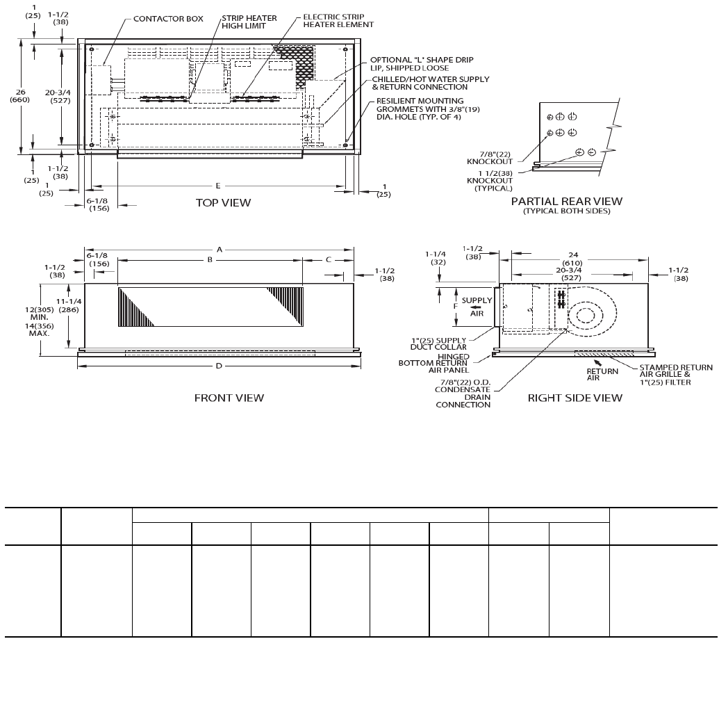
02 200 211/4311/416 13 181/461/483/4193/41 1 0.83 36
03 300 251/4361/420 14 221/461/483/4233/41 1 1.08 39
04 400 311/4431/426 15 281/461/483/4293/42 1 1.35 49
06 600 361/4431/431 10 331/471/210 343/42 1 1.88 59
08 800 431/4571/438 17 401/471/210 413/42 1 2.31 64
10 1000 571/4651/452 11 541/471/210 553/44 2 3.16 95
12 1200 651/4751/460 13 621/471/210 633/44 2 3.65 107
NOTES:
1. Right hand unit shown; left hand unit opposite. Coil connection
locations are ±5/8-in.
2. Unit sizes 02 and 03 have one motor, one blower; sizes 04
through 08 have one motor, 2 blowers; sizes 10 and 12 have
2 motors, 4 blowers.
3. Standard 3-row coil shown.
4. Overall unit dimension increases by 4 in. with optional electric
heat.
5. Not shown: 3-speed fan switch; wall plate, closed cell foam on
main drain pan.
6. Units have galvanized finish.
7. For optional coil connections, view 42CA-203-1 using the Fan Coil
Builder.
8. Dimensions shown in inches (mm).
Fig. 1 — 42CA Furred-In Horizontal Unit Dimensions
a42-4099.eps
5
LEGEND
1—Junction Box (remote mount)
2—Flexible Metal Conduit
3 — Strip Heater High Limit
4 — Electric Strip Heater Element
5 — Tell-Tale Drain Conn, 5/8-in. OD (optional)
6—Drain Conn, 7/8-in. OD
7—Drip Lip (optional)
8—Supply Duct Collar, 1-in.
9—Air Vent, 1/8-in. MPT
10 — Return Conn, 5/8-in. OD
11 — Supply Conn, 5/8-in. OD
12 — Hanger Slots (4), Rubber Grommet
has 3/8-in. Diameter Hole
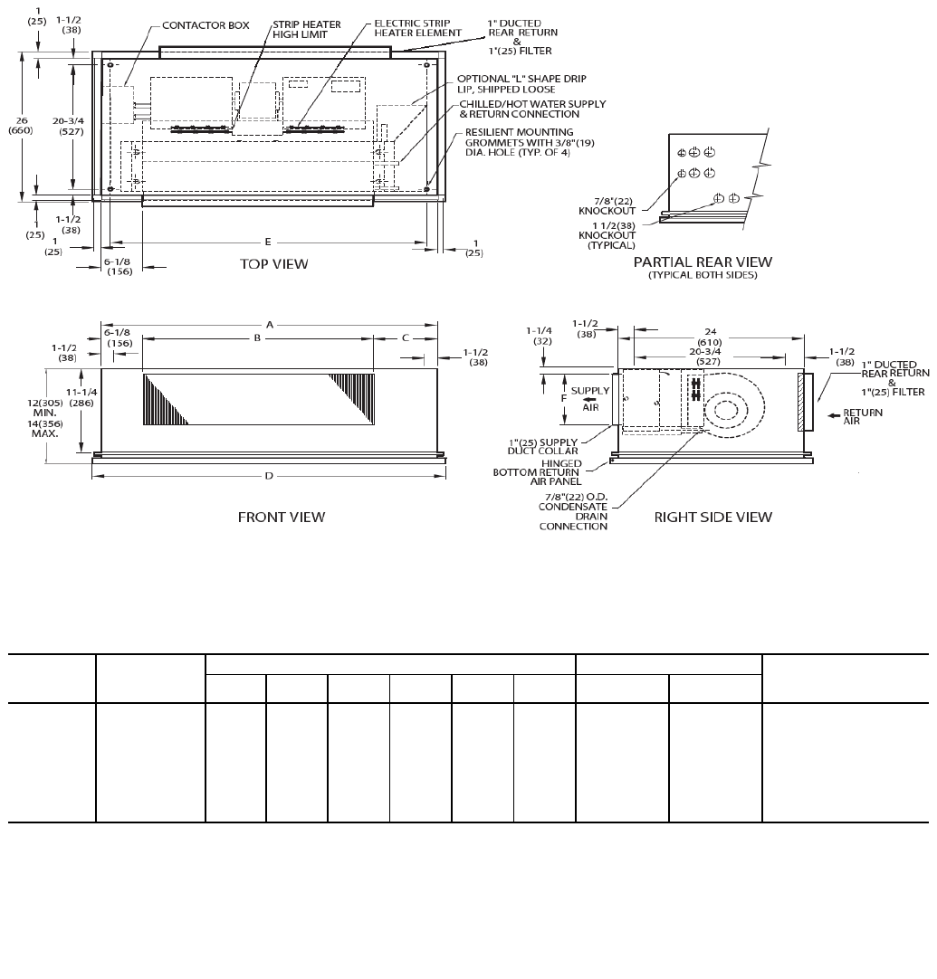
NOTES:
1. Right hand unit shown; left hand unit opposite. Coil connection
locations are ±5/8-in.
2. Unit sizes 02 and 03 have one motor, one blower; sizes 04
through 08 have one motor, 2 blowers; sizes 10 and 12 have
2 motors, 4 blowers.
3. Standard 3-row coil shown.
4. Overall unit dimension increases by 4 in. with optional electric
heat.
5. Not shown: 3-speed fan switch; wall plate, closed cell foam on
main drain pan.
6. Units have galvanized finish.
7. For optional coil connections, view 42CA-203-1 using the Fan Coil
Builder.
8. Dimensions shown in inches (mm).
*Unit weights are based on dry coils and minimum rows. Weights exclude packaging, valves, and other components.
UNIT
SIZE
NOM
AIRFLOW
(Cfm)
DIMENSIONS (in.) QTY/UNIT FACE
AREA
(sq ft)
UNIT
WEIGHT*
(lb)
AA’BD’E F GH
Blower Motor
02 200 211/4311/416 13 181/461/483/4193/41 1 0.83 38
03 300 251/4361/420 14 221/461/483/4233/41 1 1.08 41
04 400 311/4431/426 15 281/461/483/4293/42 1 1.35 51
06 600 361/4431/431 10 331/471/210 343/42 1 1.88 61
08 800 431/4571/438 17 401/471/210 413/42 1 2.31 66
10 1000 571/4651/452 11 541/471/210 553/44 2 3.16 97
12 1200 651/4751/460 13 621/471/210 633/44 2 3.65 109
Fig. 2 — 42CA Furred-In Horizontal Unit with Electric Heat Dimensions
a42-4100.eps
6
NOTES:
1. Right hand unit with standard 3-row coil shown; left hand unit opposite. Coil
connection locations are ±5/8-in.
2. Unit sizes 02 and 03 have one motor, one blower; sizes 04 through 08 have
one motor, 2 blowers; sizes 10 and 12 have 2 motors, 4 blowers.
3. Standard 3-row coil shown.
4. Unit available with bottom or rear return air.
5. Dimension increases by 4 in. with optional electric heat.
6. Not shown: 3-speed fan switch; wall plate, 1/2-in. fiberglass insulation on
inside of plenum, closed cell foam on main drain pan.
7. Units have galvanized finish.
8. For optional coil connections, view 42CA-203-1 using the Fan Coil Builder.
9. Dimensions shown in inches (mm).
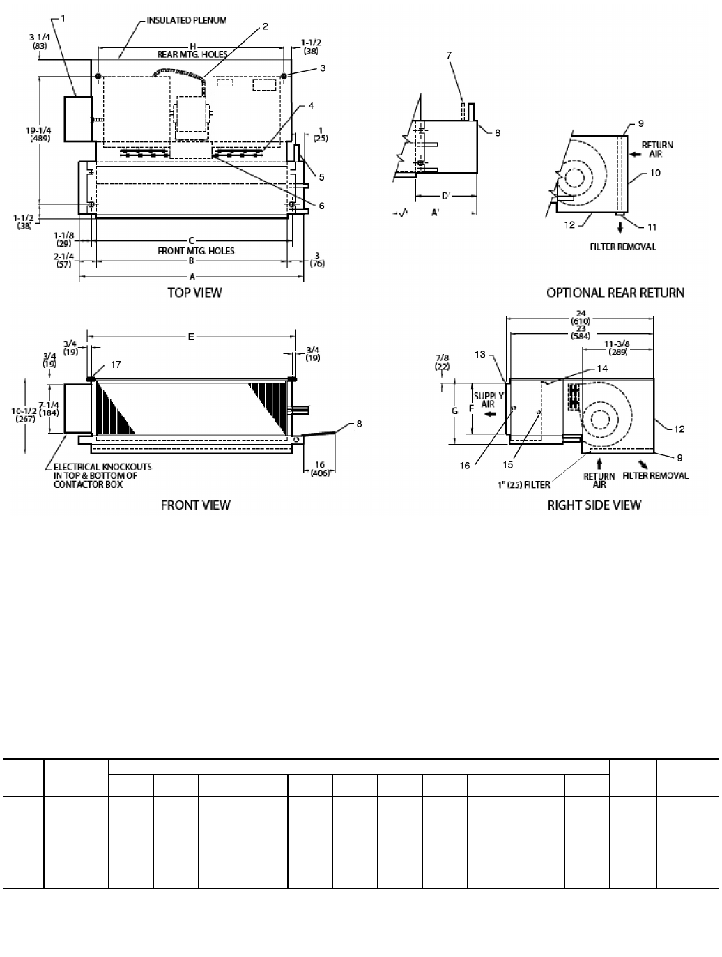
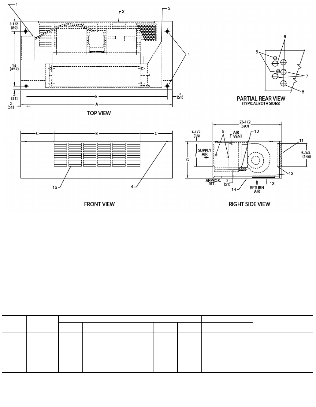
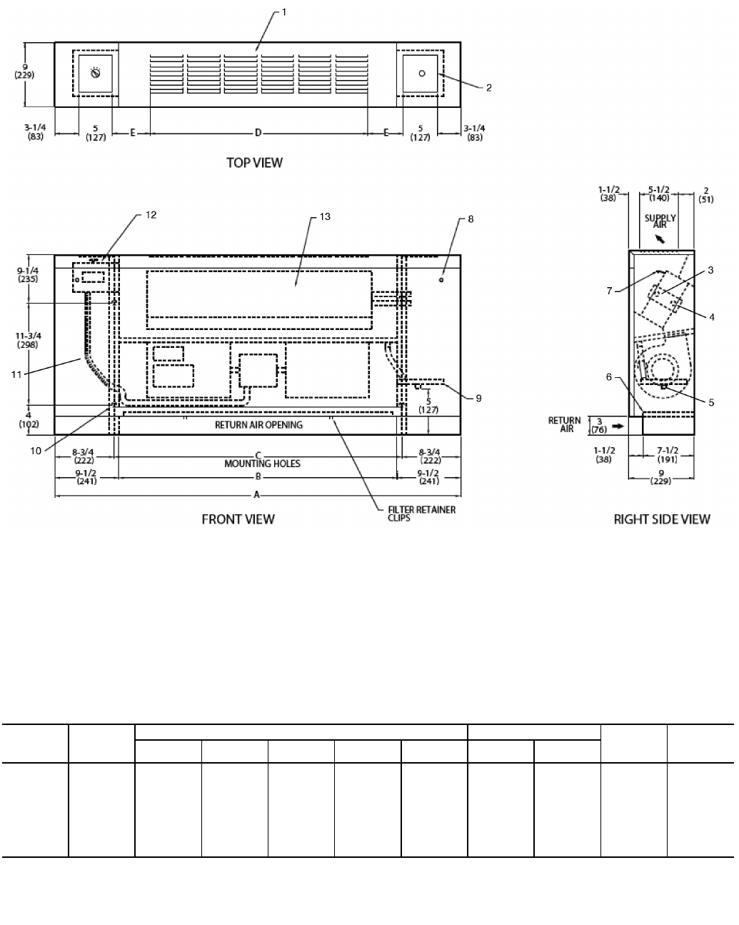
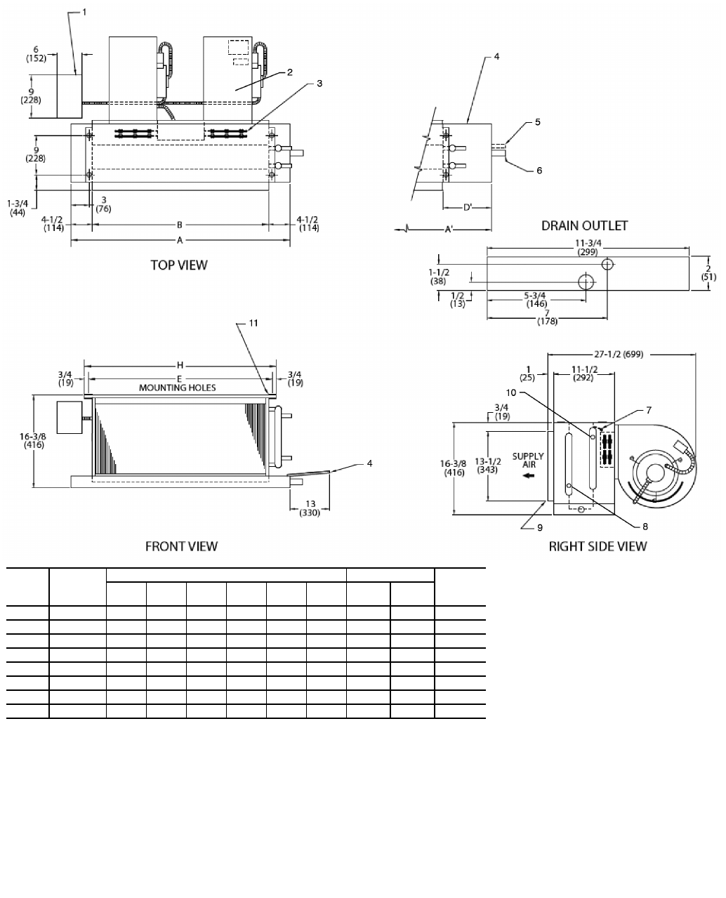
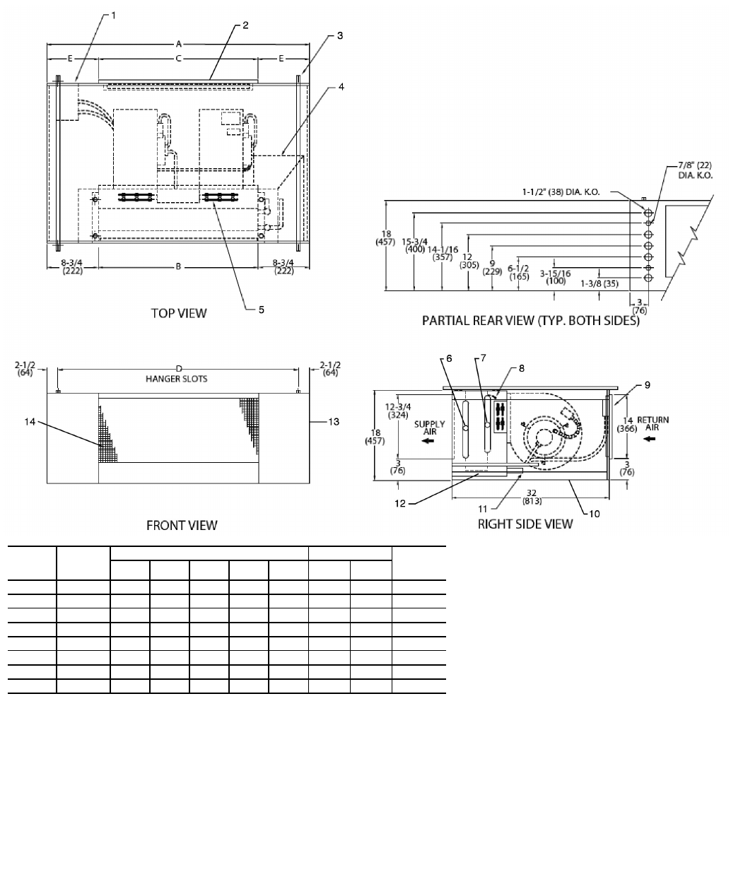
LEGEND
1— Junction Box, 4 in. x 4 in.
2— Flexible Metal Conduit
3— Mounting Bracket
4— Drain Conn, 7/8-in. OD
5— Tell-Tale Drain Conn, 5/8-in. OD (optional)
6— Drip Lip (optional, shipped loose)
7— Filter
8— Return Duct Collar, 1-in.
9— Filter Access Panel
10 — Access Panel
11 — Supply Duct Collar, 1-in.
12 — Air Vent, 1/8-in. MPT
13 — Return Conn, 5/8-in. OD
14 — Supply Conn, 5/8-in. OD
15 — Hanger Slots (4), Rubber Grommet has
3/8-in. Diameter Hole
*Unit weights are based on dry coils and minimum rows. Weights exclude packaging, valves, and other components.
UNIT
SIZE
NOM
AIRFLOW
(Cfm)
DIMENSIONS (in.) QTY/UNIT FACE
AREA
(sq ft)
UNIT
WEIGHT*
(lb)
AA’B CD’E F GH
Blower Motor
02 200 211/4311/416 181/413 193/461/483/4153/81 1 0.83 55
03 300 251/4361/420 221/414 233/461/483/4193/81 1 1.08 60
04 400 311/4431/426 281/415 293/461/483/4253/82 1 1.35 70
06 600 361/4431/431 331/410 343/471/210 303/82 1 1.88 82
08 800 431/4571/438 401/417 413/471/210 373/82 1 2.31 95
10 1000 571/4651/452 541/411 553/471/210 513/84 2 3.16 135
12 1200 651/4751/460 621/413 633/471/210 593/84 2 3.65 154
a42-4101
Fig. 3 — 42CE Furred-In Horizontal Unit with Plenum Dimensions
7
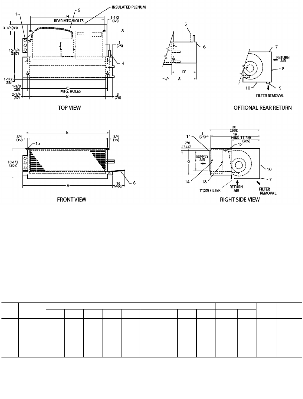
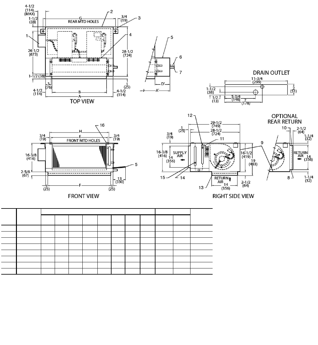
NOTES:
1. Right hand unit with standard 3-row coil shown; left hand unit opposite. Coil
connection locations are ±5/8-in.
2. Unit sizes 02 and 03 have one motor, one blower; sizes 04 through 08 have
one motor, 2 blowers; sizes 10 and 12 have 2 motors, 4 blowers.
3. Standard 3-row coil shown.
4. Unit available with bottom or rear return air.
5. Dimension increases by 4 in. with optional electric heat.
6. Not shown: 3-speed fan switch; wall plate, 1/2-in. fiberglass insulation on
inside of plenum, closed cell foam on main drain pan.
7. Units have galvanized finish.
8. For optional coil connections, view 42CA-203-1 using the Fan Coil Builder.
9. Dimensions shown in inches (mm).
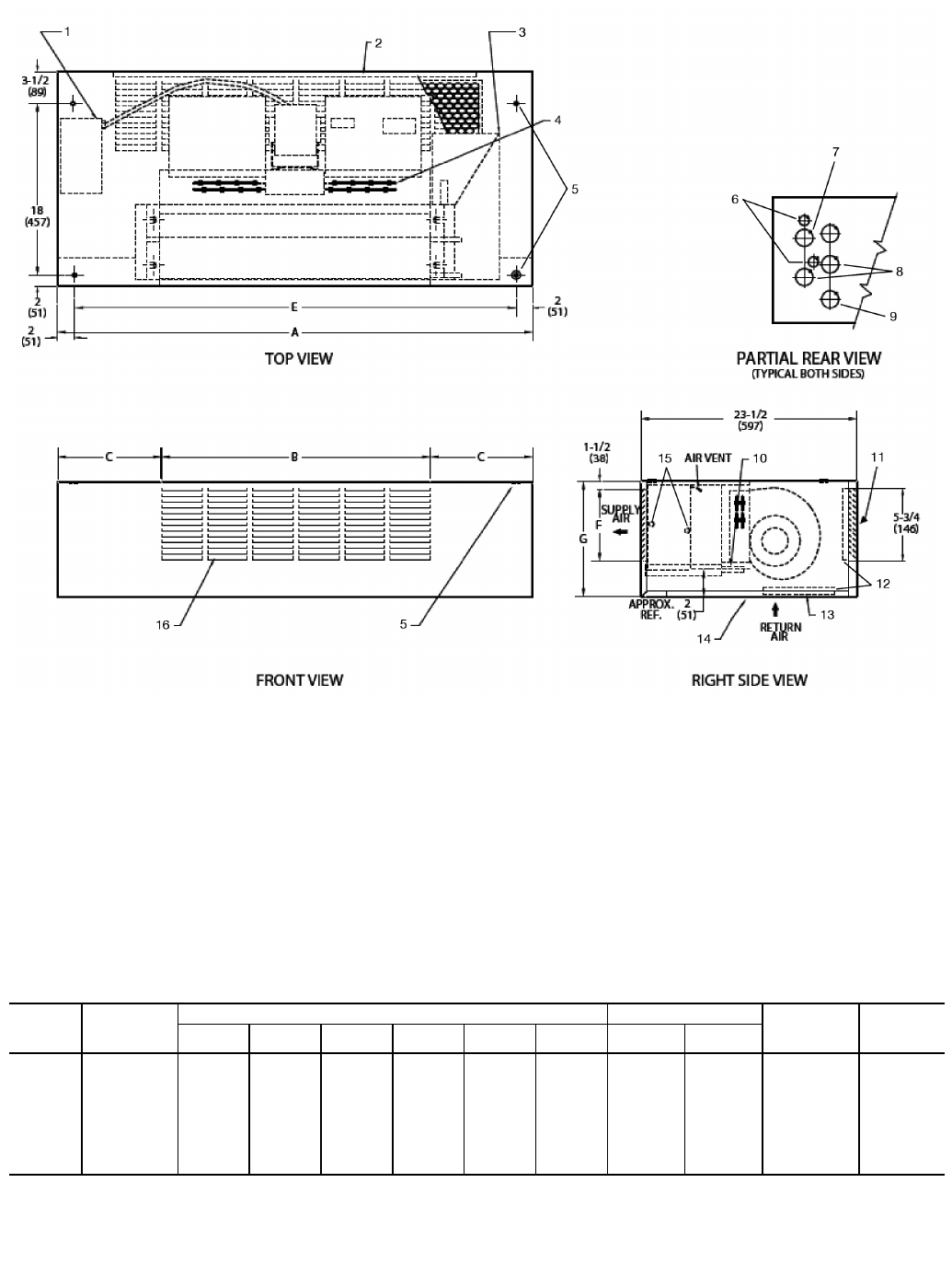
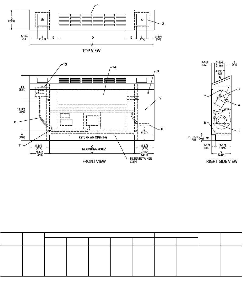
LEGEND
1— Junction Box, 4 in. x 4 in.
2— Flexible Metal Conduit
3— Mounting Bracket
4— Electric Strip Heater Element
5— Drain Conn, 7/8-in. OD
6— Strip Heater High Limit
7— Tell-Tale Drain Conn, 5/8-in. OD (optional)
8— Drip Lip (optional, shipped loose)
9— Filter
10 — Return Duct Collar, 1-in.
11 — Filter Access Panel
12 — Access Panel
13 — Supply Duct Collar, 1-in.
14 — Air Vent, 1/8-in. MPT
15 — Return Conn, 5/8-in. OD
16 — Supply Conn, 5/8-in. OD
17 — Hanger Slots (4), Rubber Grommet has
3/8-in. Diameter Hole
*Unit weights are based on dry coils and minimum rows. Weights exclude packaging, valves, and other components.
UNIT
SIZE
NOM
AIRFLOW
(Cfm)
DIMENSIONS (in.) QTY/UNIT FACE
AREA
(sq ft)
UNIT
WEIGHT*
(lb)
AA’B CD’E F G H
Blower Motor
02 200 211/4311/416 181/413 193/461/483/4153/81 1 0.83 57
03 300 251/4361/420 221/414 233/461/483/4193/81 1 1.08 62
04 400 311/4431/426 281/415 293/461/483/4253/82 1 1.35 72
06 600 361/4431/431 331/410 343/471/210 303/82 1 1.88 84
08 800 431/4571/438 401/417 413/471/210 373/82 1 2.31 97
10 1000 571/4651/452 541/411 553/471/210 513/84 2 3.16 137
12 1200 651/4751/460 621/413 633/471/210 593/84 2 3.65 156
A42-4102
Fig. 4 — 42CE Furred-In Horizontal Unit with Plenum and Electric Heat Dimensions
8
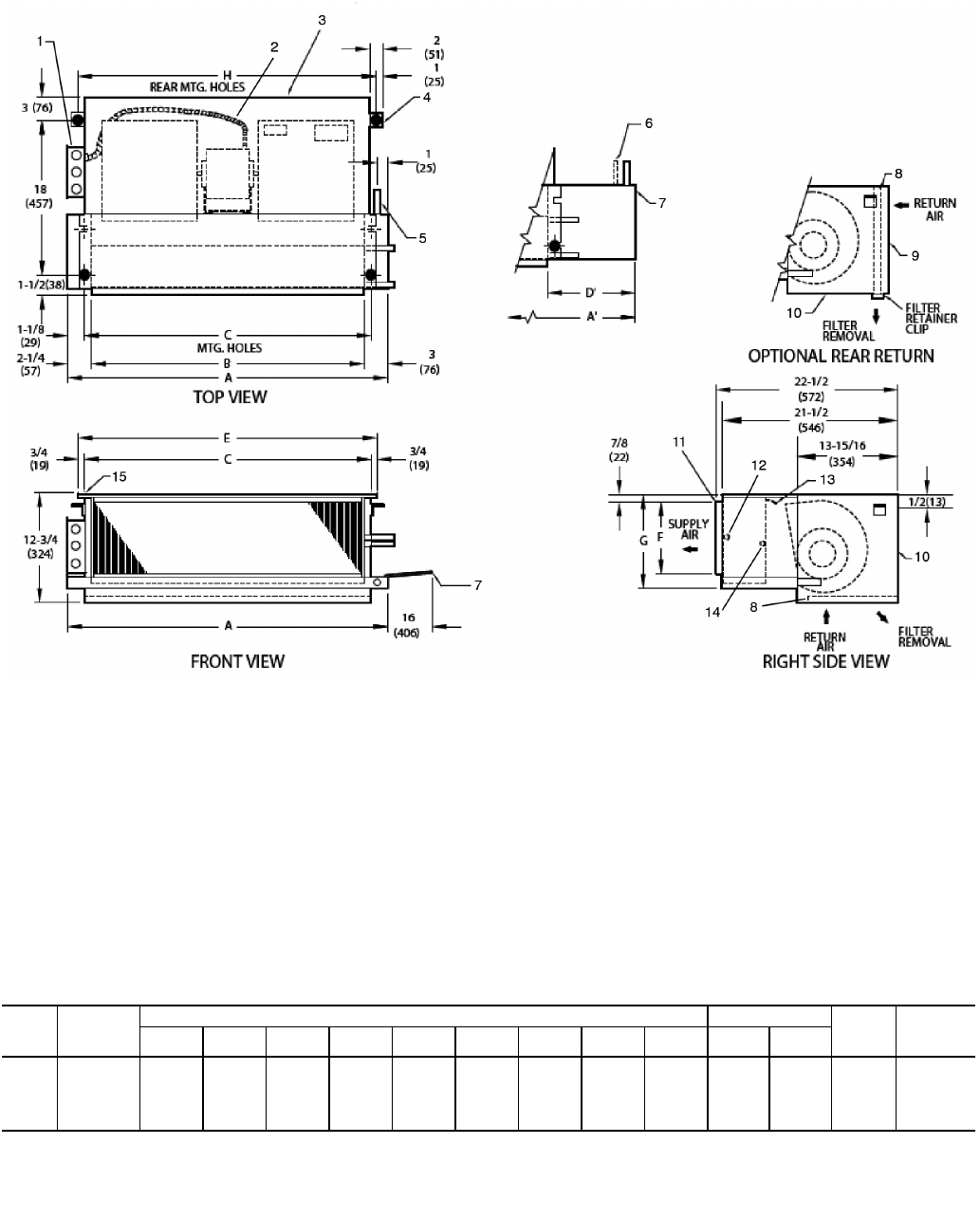
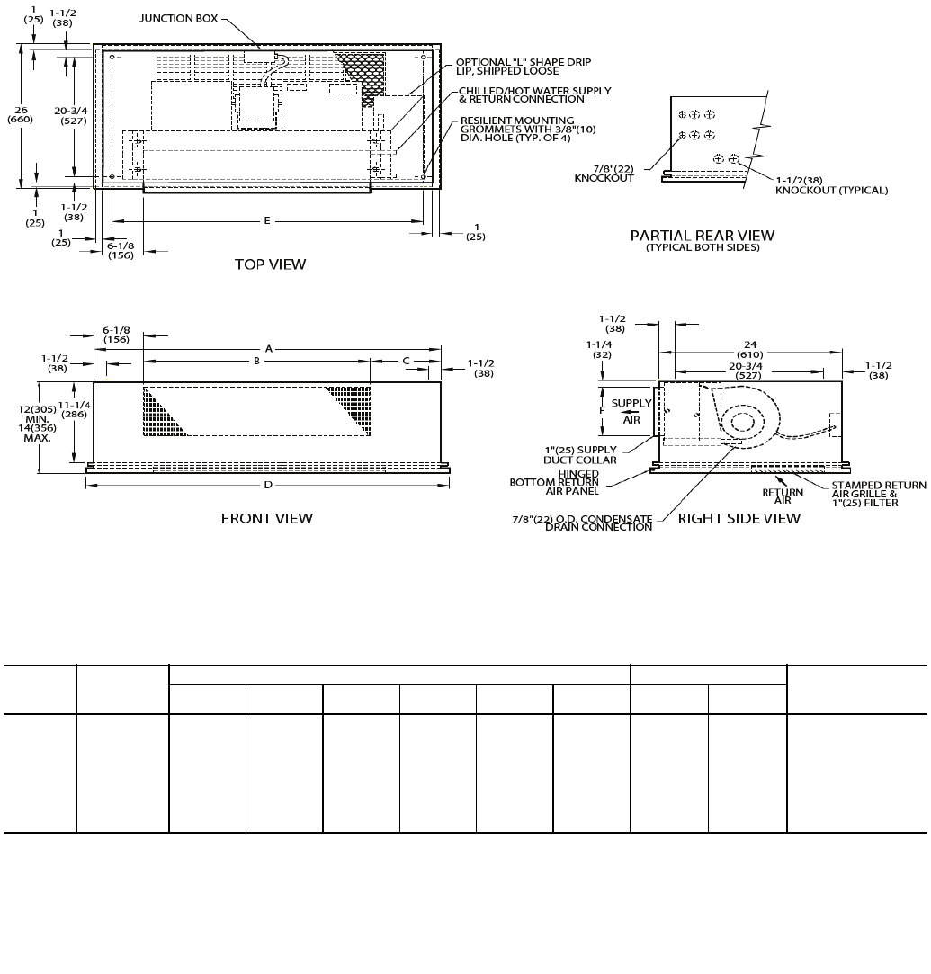
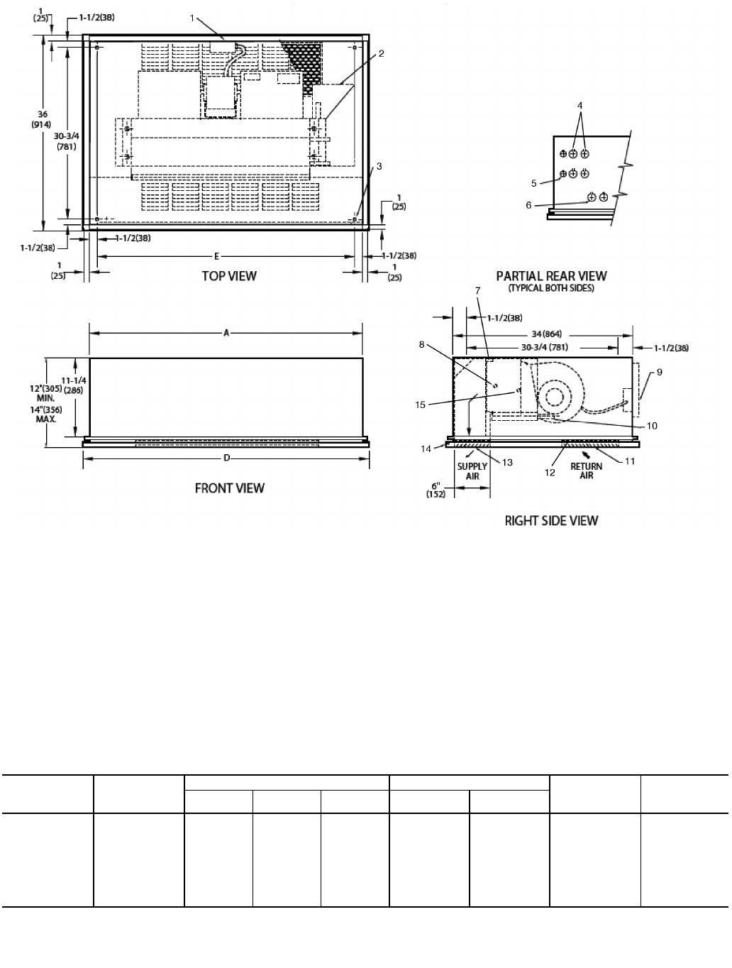
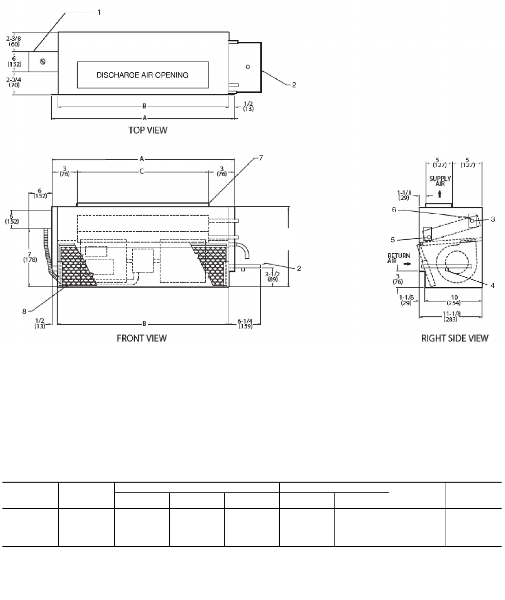
LEGEND
1— Junction Box, Installed with Plenum
2— Flexible Metal Conduit
3— Insulated Plenum
4— Mounting Bracket
5— Drain Conn, 7/8-in. OD
6— Tell-Tale Drain Conn, 5/8-in. OD (optional)
7— Drip Lip (optional, shipped loose)
8— Filter
9— Return Duct Collar, 1-in.
10 — Access Panel
11 — Supply Duct Collar, 1-in.
12 — Supply Conn, 5/8-in. OD
13 — Air Vent, 1/8-in. MPT
14 — Return Conn, 5/8-in. OD
15 — Hanger Slots (4), Rubber Grommet has
3/8-in. Diameter Hole
*Unit weights are based on dry coils and minimum rows. Weights exclude packaging, valves, and other components.
UNIT
SIZE
NOM
AIRFLOW
(Cfm)
DIMENSIONS (in.) QTY/UNIT FACE
AREA
(sq ft)
UNIT
WEIGHT*
(lb)
AA’B CD’E F G H
Blower Motor
04 400 311/4431/426 281/415 293/461/483/4301/42 1 1.35 84
06 600 361/4431/434 331/410 343/471/210 351/42 1 1.88 97
08 800 431/4571/438 401/417 413/471/210 421/42 1 2.31 110
10 1000 571/4651/452 541/411 553/471/210 561/44 2 3.16 163
NOTES:
1. Right hand unit shown; left hand unit opposite. Coil connection
locations are ±5/8-in.
2. Unit sizes 04 thru 08 have one motor, 2 blowers; size 10 has
2 motors, 4 blowers.
3. Refer to above figure for configuration of filter and track if
installed in optional plenum.
4. Dimension increases by 4 in. with optional electric heat.
5. Not shown: 3-speed fan switch; wall plate, 1/2-in. fiberglass
insulation on inside of plenum (when installed), closed cell
insulation on main drain pan.
6. Units have galvanized finish.
7. For optional coil connections, view 42CA-203-1 using the Fan
Coil Builder.
8. Dimensions shown in inches (mm).
A42-4103
Fig. 5 — 42CF Furred-In High-Static Horizontal Unit with Plenum Dimensions
9
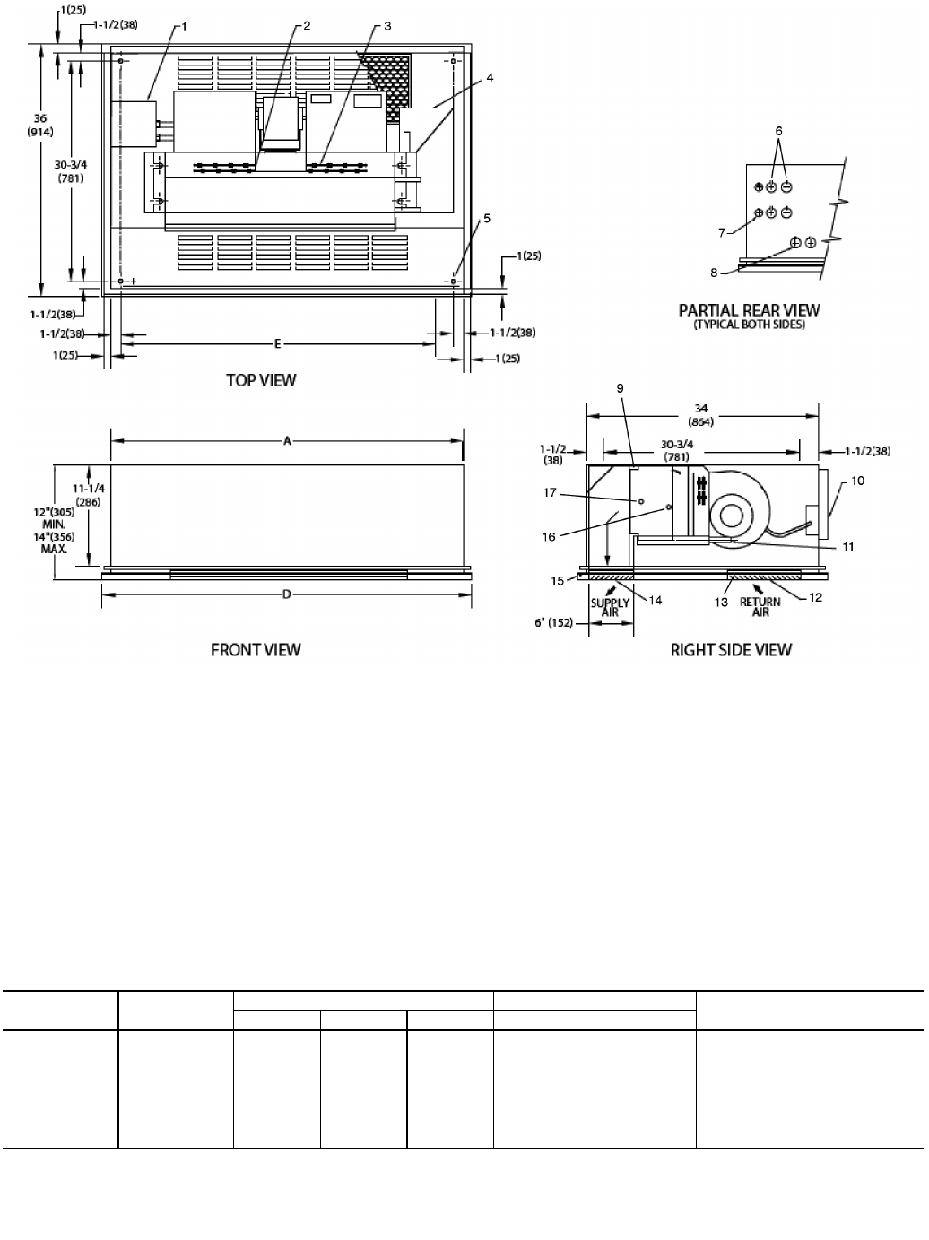
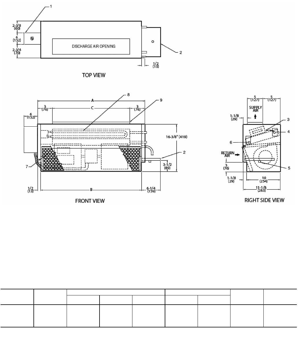
LEGEND
1— Junction Box, Installed with Plenum
2— Plenum
3— Flexible Metal Conduit
4— Mounting Bracket
5— Electric Strip Heater Element
6— Drain Conn, 7/8-in. OD
7— Drip Lip (optional, shipped loose)
8— Tell-Tale Drain Conn, 5/8-in. OD (optional)
9— Filter
10 — Return Duct Collar, 1-in.
11 — Air Vent, 1/8-in. MPT
12 — Access Panel
13 — Return Conn, 5/8-in. OD
14 — Supply Conn, 5/8-in. OD
15 — Supply Duct Collar, 1-in.
16 — Hanger Slots (4), Rubber Grommet has
3/8-in. Diameter Hole
NOTES:
1. Right hand unit shown; left hand unit opposite. Coil connection
locations are ±5/8-in.
2. Unit sizes 04 thru 08 have one motor, 2 blowers; size 10 has
2 motors, 4 blowers.
3. Refer to above figure for configuration of filter and track if
installed in optional plenum.
4. Dimension increases by 4 in. with optional electric heat.
5. Not shown: 3-speed fan switch; wall plate, 1/2-in. fiberglass
insulation on inside of plenum (when installed), closed cell
insulation on main drain pan.
6. Units have galvanized finish.
7. For optional coil connections, view 42CA-203-1 using the Fan
Coil Builder.
8. Dimensions shown in inches (mm).
*Unit weights are based on dry coils and minimum rows. Weights exclude packaging, valves, and other components.
UNIT
SIZE
NOM
AIRFLOW
(Cfm)
DIMENSIONS (in.) QTY/UNIT FACE
AREA
(sq ft)
UNIT
WEIGHT*
(lb)
AA’B CD’E F G H
Blower Motor
04 400 311/4431/426 281/415 293/461/483/4301/42 1 1.35 84
06 600 361/4431/434 331/410 343/471/210 351/42 1 1.88 97
08 800 431/4571/438 401/417 413/471/210 421/42 1 2.31 110
10 1000 571/4651/452 541/411 553/471/210 561/44 2 3.16 163
A42-4104
Fig. 6 — 42CF Furred-In Horizontal Unit with Plenum and Electric Heat Dimensions
10
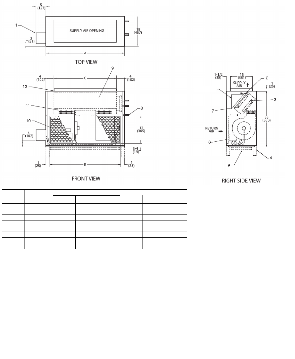
LEGEND
1— Junction Box, 4 in. x 4 in.
2— Optional Return Air Location
3— Optional Drip Lip, shipped loose
4— Mounting Holes (4), Rubber Grommets
have 3/8-in. Diameter Hole
5— Electrical KO, 7/8-in. Diameter
6— Return KO, 1-in. Diameter
7— Supply KO, 11/2-in. Diameter
8— Drain KO, 11/2-in. Diameter
9— Supply, Return Connections, 5/8-in. OD
10 — Drain Connection, 7/8-in. OD
11 — Optional Valve Package (inside cabinet)
12 — Filter
13 — Standard Stamped-Return Air Grille
14 — Removable Hinged Access Panel
15 — Supply Grille, Stamped, Standard
*Unit weights are based on dry coils and minimum rows. Weights exclude packaging, valves, and other components.
UNIT
SIZE
NOM
AIRFLOW
(Cfm)
DIMENSIONS (in.) QTY/UNIT FACE
AREA
(sq ft)
UNIT
WEIGHT*
(lb)
ABCEFG
Blower Motor
02 200 38 171/8107/16 34 53/411 1 1 0.83 98
03 300 42 211/2101/438 53/411 1 1 1.08 118
04 400 48 257/8111/16 44 53/411 2 1 1.35 126
06 600 53 345/893/16 49 63/412 2 1 1.88 168
08 800 60 39 101/256 63/412 2 1 2.31 176
10 1000 74 521/81015/16 70 63/412 4 2 3.16 215
12 1200 82 607/8109/16 78 63/412 4 2 3.65 245
NOTES:
1. Right hand unit shown; left hand unit opposite. Coil connection locations
are ±5/8-in.
2. Unit sizes 02 and 03 have one motor, one blower; sizes 04 through 08
have one motor, 2 blowers; sizes 10 and 12 have 2 motors, 4 blowers.
3. Cabinet has an Arctic White baked finish.
4. Refer to supply and return connections above for coil stub-out locations.
5. Not shown: optional drip lip, 3-speed fan switch; wall plate, 1/2-in. fiber-
glass insulation on inside of casing, closed cell foam on main drain pan.
6. For optional coil connections, view 42CA-203-1 using the Fan Coil
Builder.
7. Valve package is factory-installed inside the cabinet when ordered with
the unit (based on component size).
8. Dimensions shown in inches (mm).
A42-4105
Fig. 7 — 42CG Horizontal Cabinet Unit Dimensions
11
LEGEND
1— Junction Box, 4 in. x 4 in.
2— Optional Stamped Rear Return Grille
3— Optional Drip Lip, shipped loose
4— Electric Strip Heater Element
5— Mounting Holes (4), Rubber Grommets
have 3/8-in. Diameter Hole
6— Electrical KO, 7/8-in. Diameter
7— Return KO, 1-in. Diameter
8— Supply KO, 11/2-in. Diameter
9— Drain KO, 11/2-in. Diameter
10 — Drain Connection, 7/8-in. OD
11 — Optional Valve Package (inside cabinet)
12 — Filter
13 — Standard Stamped-Return Air Grille
14 — Removable Hinged Access Panel
15 — Supply, Return Connections, 5/8-in. OD
16 — Supply Grille, Stamped, Standard
NOTES:
1. Right hand unit shown; left hand unit opposite. Coil connection
locations are ±5/8-in.
2. Unit sizes 02 and 03 have one motor, one blower; sizes 04
through 08 have one motor, 2 blowers; sizes 10 and 12 have
2 motors, 4 blowers.
3. Cabinet has an Arctic White baked finish.
4. Refer to supply and return connections above for coil stub-out
locations.
5. Not shown: optional drip lip, 3-speed fan switch; wall plate,
1/2-in. fiberglass insulation on inside of casing, closed cell foam
on main drain pan.
6. For optional coil connections, view 42CA-203-1 using the Fan
Coil Builder.
7. Valve package is factory-installed inside the cabinet when
ordered with the unit (based on component size).
8. Dimensions shown in inches (mm).
*Unit weights are based on dry coils and minimum rows. Weights exclude packaging, valves, and other components.
UNIT
SIZE
NOM
AIRFLOW
(Cfm)
DIMENSIONS (in.) QTY/UNIT FACE
AREA
(sq ft)
UNIT
WEIGHT*
(lb)
ABCEFG
Blower Motor
02 200 38 171/8107/16 34 53/411 1 1 0.83 98
03 300 42 211/2101/438 53/411 1 1 1.08 118
04 400 48 257/8111/16 44 53/411 2 1 1.35 126
06 600 53 345/893/16 49 63/412 2 1 1.88 168
08 800 60 39 101/256 63/412 2 1 2.31 176
10 1000 74 521/81015/16 70 63/412 4 2 3.16 215
12 1200 82 607/8109/16 78 63/412 4 2 3.65 245
A42-4106
Fig. 8 — 42CG Horizontal Cabinet with Electric Heat Dimensions
12
UNIT
SIZE
NOM
AIRFLOW
(Cfm)
DIMENSIONS (in.) QTY/UNIT BOTTOM RETURN
FILTER SIZE, (in.)
ABCDEFBlowerMotor
02 200 35 16 123/437 32 6 1 1 10 x 28
03 300 35 20 83/437 32 6 1 1 10 x 28
04 400 41 26 83/443 38 6 2 1 10 x 33
06 600 53 31 153/455 50 7 2 1 10 x 45
08 800 53 38 83/455 50 7 2 1 10 x 45
10 1000 75 52 163/477 72 7 4 2 10 x 62
12 1200 75 60 83/477 72 7 4 2 10 x 62
NOTES:
1. Right hand unit shown; left hand unit opposite.
2. Internal factory valve package and drains may not align with
cabinet knockouts.
3. Dimensions shown in inches (mm). All dimensions are ±1/4 in.
4. Bottom panel is Arctic White polyester powder coat paint.
A42-4149
Fig. 9 — 42CK Horizontal Cabinet Unit with Telescopic Access Panel,
Front Supply, and Bottom Return Dimensions
13
NOTES:
1. Right hand unit shown; left hand unit opposite.
2. Internal factory valve package and drains may not align with
cabinet knockouts.
3. Dimensions shown in inches (mm). All dimensions are ±1/4 in.
4. Bottom panel is Arctic White polyester powder coat paint.
UNIT
SIZE
NOM
AIRFLOW
(Cfm)
DIMENSIONS (in.) QTY/UNIT BOTTOM RETURN
FILTER SIZE, (in.)
A B C D E F Blower Motor
02 200 35 16 123/437 32 6 1 1 10 x 28
03 300 35 20 83/437 32 6 1 1 10 x 28
04 400 41 26 83/443 38 6 2 1 10 x 33
06 600 53 31 153/455 50 7 2 1 10 x 45
08 800 53 38 83/455 50 7 2 1 10 x 45
10 1000 75 52 163/477 72 7 4 2 10 x 62
12 1200 75 60 83/477 72 7 4 2 10 x 62
a42-4150
Fig. 10 — 42CK Horizontal Cabinet Unit with Telescopic Access Panel,
Front Supply, Bottom Return, and Heater Dimensions

14
NOTES:
1. Right hand unit shown; left hand unit opposite.
2. Internal factory valve package and drains may not align with
cabinet knockouts.
3. Dimensions shown in inches (mm). All dimensions are ±1/4 in.
4. Bottom panel is Arctic White polyester powder coat paint.
UNIT
SIZE
NOM
AIRFLOW
(Cfm)
DIMENSIONS (in.) QTY/UNIT REAR RETURN
FILTER SIZE, (in.)
ABCDEFBlowerMotor
02 200 35 16 123/437 32 6 1 1 7 x 21
03 300 35 20 83/437 32 6 1 1 7 x 21
04 400 41 26 83/443 38 6 2 1 7 x 27
06 600 43 31 153/455 50 7 2 1 7 x 38
08 800 43 38 83/455 50 7 2 1 7 x 38
10 1000 75 52 163/477 72 7 4 2 7 x 52
12 1200 75 60 83/477 72 7 4 2 7 x 52
a42-4151
Fig. 11 — 42CK Horizontal Cabinet Unit with Telescopic Access Panel,
Front Supply, and Rear Return Dimensions
15
NOTES:
1. Right hand unit shown; left hand unit opposite.
2. Internal factory valve package and drains may not align with
cabinet knockouts.
3. Dimensions shown in inches (mm). All dimensions are ±1/4 in.
4. Bottom panel is Arctic White polyester powder coat paint.
UNIT
SIZE
NOM
AIRFLOW
(Cfm)
DIMENSIONS (in.) QTY/UNIT REAR RETURN
FILTER SIZE, (in.)
ABCDEFBlowerMotor
02 200 35 16 123/437 32 6 1 1 7 x 21
03 300 35 20 83/437 32 6 1 1 7 x 21
04 400 41 26 83/443 38 6 2 1 7 x 27
06 600 43 31 153/455 50 7 2 1 7 x 38
08 800 43 38 83/455 50 7 2 1 7 x 38
10 1000 75 52 163/477 72 7 4 2 7 x 52
12 1200 75 60 83/477 72 7 4 2 7 x 52
a42-4152
Fig. 12 — 42CK Horizontal Cabinet Unit with Telescopic Access Panel,
Front Supply, Rear Return, and Heater Dimensions
16
LEGEND
1— Junction Box, 4 in. x 4 in.
2— Optional Drip Lip, shipped loose
3— Mounting Holes (4), Rubber Grommets
have 3/8-in. Diameter Hole
4— Piping KO, 11/2-in. Diameter
5— Electrical KO, 7/8-in. Diameter
6— Drain KO, 11/2-in. Diameter
7— Supply Duct Collar
8— Return Connection, 5/8-in. OD.
9— Optional Rear Return. Consult factory for
collar dimensions.
10 — Drain, 7/8-in. OD.
11 — Stamped Bottom Return Air Grille
12 — Filter
13 — Stamped Air Supply Grille
14 — Hinged Bottom Access Panel
15 — Supply Connection, 5/8-in. OD.
*Unit weights are based on dry coils and minimum rows. Weights exclude packaging, valves, and other components.
UNIT
SIZE
NOM
AIRFLOW
(Cfm)
DIMENSIONS (in.) QTY/UNIT FACE AREA
(sq ft)
UNIT WEIGHT*
(lb)
ADE
Blower Motor
02 200 35 37 32 1 1 0.83 115
03 300 35 37 32 1 1 1.08 120
04 400 41 43 38 2 1 1.35 135
06 600 53 55 50 2 1 1.88 150
08 800 53 55 50 2 1 2.31 155
10 1000 75 77 72 4 2 3.16 227
12 1200 75 77 72 4 2 3.65 241
NOTES:
1. Right hand unit shown; left hand unit opposite. Coil connection
locations are ±5/8-in.
2. Unit sizes 02 and 03 have one motor, one blower; sizes 04
through 08 have one motor, 2 blowers; sizes 10 and 12 have
2 motors, 4 blowers.
3. Bottom access panel has an Arctic White baked finish.
4. Refer to supply and return connections above for coil stub-out
locations.
5. Not shown: optional drip lip, 3-speed fan switch; wall plate,
1/2-in. fiberglass insulation on inside of casing, closed cell foam
on main drain pan.
6. For optional coil connections, view 42CA-203-1 using the Fan
Coil Builder.
7. Valve package is factory-installed inside the cabinet when
ordered with the unit (based on component size).
8. Bottom return or bottom supply is an ETO (engineering to order)
request.
9. Dimensions shown in inches (mm). A42-4107
Fig. 13 — 42CK Horizontal Cabinet Unit with Telescopic Access Panel
17
LEGEND
1— Junction Box, 4 in. x 4 in.
2— Strip Heater High Limit
3— Electric Strip Heater Element
4— Optional Drip Lip, shipped loose
5— Mounting Holes (4), Rubber Grommets
have 3/8-in. Diameter Hole
6— Piping KO, 11/2-in. Diameter
7— Electrical KO, 7/8-in. Diameter
8— Drain KO, 11/2-in. Diameter
9— Supply Duct Collar
10 — Optional Rear Return. Consult factory for
collar dimensions.
11 — Drain, 7/8-in. OD.
12 — Stamped Bottom Return Air Grille
13 — Filter
14 — Stamped Air Supply Grille
15 — Hinged Bottom Access Panel
16 — Supply Connection, 5/8-in. OD.
17 — Return Connection, 5/8-in. OD.
NOTES:
1. Right hand unit shown; left hand unit opposite. Coil connection
locations are ±5/8-in.
2. Unit sizes 02 and 03 have one motor, one blower; sizes 04
through 08 have one motor, 2 blowers; sizes 10 and 12 have
2 motors, 4 blowers.
3. Bottom access panel has an Arctic White baked finish.
4. Refer to supply and return connections above for coil stub-out
locations.
5. Not shown: optional drip lip, 3-speed fan switch; wall plate,
1/2-in. fiberglass insulation on inside of casing, closed cell foam
on main drain pan.
6. For optional coil connections, view 42CA-203-1 using the Fan
Coil Builder.
7. Valve package is factory-installed inside the cabinet when
ordered with the unit (based on component size).
8. Bottom return or bottom supply is an ETO (engineering to order)
request.
9. Dimensions shown in inches (mm).
*Unit weights are based on dry coils and minimum rows. Weights exclude packaging, valves, and other components.
UNIT SIZE NOM AIRFLOW
(Cfm)
DIMENSIONS (in.) QTY/UNIT FACE AREA
(sq ft)
UNIT WEIGHT*
(lb)
ADEBlowerMotor
02 200 35 37 32 1 1 0.83 117
03 300 35 37 32 1 1 1.08 122
04 400 41 43 38 2 1 1.35 137
06 600 53 55 50 2 1 1.88 152
08 800 53 55 50 2 1 2.31 157
10 1000 75 77 72 4 2 3.16 229
12 1200 75 77 72 4 2 3.65 243
A42-4108
Fig. 14 — 42CK Horizontal Cabinet with Telescopic Access Panel and Electric Heat Dimensions

18
LEGEND
1— Optional Unit Mounted Control Box
2— Wall Mounting Holes (4), 3/4-in. Diameter
3— Drain, 3/4-in. MPT
4— Drain Pan, Auxiliary, Shipped Loose
5— Supply Conn, 5/8-in. OD
6— Return Conn, 5/8-in. OD
7— Filter
8— Air Vent, 1/8-in. MPT
9— Discharge Opening
10 — Flexible Conduit
11 — Front Access Panel
*Unit weights are based on dry coils and minimum rows. Weights exclude packaging, valves, and other components.
UNIT
SIZE
NOM
AIRFLOW
(Cfm)
DIMENSIONS (in.) QTY/UNIT FACE
AREA
(sq ft)
UNIT
WEIGHT*
(lb)
ABCD
Blower Motor
02 200 25 22 231/216 1 1 0.83 65
03 300 29 26 271/220 1 1 1.08 80
04 400 35 32 331/226 2 1 1.35 90
06 600 45 42 431/236 2 1 1.88 112
08 800 47 44 451/238 2 1 2.31 115
10 1000 61 58 591/252 4 2 3.16 140
12 1200 69 66 671/260 4 2 3.65 170
NOTES:
1. Right hand unit shown; left hand unit opposite. Coil connection locations
are ± 5/8-in.
2. Unit sizes 02 and 03 have one motor, one blower; sizes 04 through 08
have one motor, 2 blowers; sizes 10 and 12 have 2 motors, 4 blowers.
3. Standard 3-row coil shown.
4. Optional unit-mounted switch box and controls, when specified, are
installed on opposite side from cooling connections.
5. Not shown: 3-speed fan switch; wall plate, 1/2-in. fiberglass insulation on
inside of casing, closed cell foam on main drain pan.
6. Units have galvanized finish.
7. For optional coil connections, view 42VA-203-1 using the Fan Coil
Builder.
8. Dimensions shown in inches (mm). A42-4109
Fig. 15 — 42VA Furred-In Vertical Unit Dimensions
19
LEGEND
1— Standard Stamped Supply Grille
2— Access Door, Fan Switch
3— Supply Conn, 5/8-in. OD
4— Return Conn, 5/8-in. OD
5— Drain, 3/4-in. MPT
6— Filter
7— Air Vent, 1/8-in. MPT
8— Front Panel Fastener
9— Drain Pan, Auxiliary, Shipped Loose
10 — Wall Mounting Holes (4), 3/4-in. Diameter
11 — Flexible Conduit
12 — Fan Switch, 3-speed
13 — Front Access Panel
NOTES:
1. Right hand unit shown; left hand unit opposite. Coil connection
locations are ± 5/8-in.
2. Unit sizes 02 and 03 have one motor, one blower; sizes 04 through
08 have one motor, 2 blowers; sizes 10 and 12 have 2 motors,
4 blowers.
3. Standard 3-row coil shown.
4. Cabinet has an Arctic White baked finish.
5. Stamped supply grille standard. Optional single or double deflec-
tion grilles available.
6. Not shown: 1/2-in. fiberglass insulation on inside of casing, closed
cell foam on main drain pan.
7. For optional coil connections, view 42VA-203-1 using the Fan Coil
Builder.
8. Dimensions shown in inches (mm).
*Unit weights are based on dry coils and minimum rows. Weights exclude packaging, valves, and other components.
UNIT
SIZE
NOM
AIRFLOW
(Cfm)
DIMENSIONS (in.) QTY/UNIT FACE
AREA
(sq ft)
UNIT
WEIGHT*
(lb)
ABCDE
Blower Motor
02 20041 2223
1/2171/435/81 1 0.83 89
03 30045 2627
1/2211/231/21 1 1.08 95
04 40051 3233
1/226 41/42 1 1.35 116
06 60061 4243
1/239 23/42 1 1.88 134
08 80063 4445
1/239 33/42 1 2.31 137
10 100077 5859
1/252 41/44 2 3.16 169
12 120085 6667
1/261 33/44 2 3.65 192
A42-4110
Fig. 16 — 42VB Vertical Cabinet Unit Dimensions
20
LEGEND
1— Standard Stamped Supply Grille
2— Access Door, Fan Switch
3— Supply Conn, 5/8-in. OD
4— Return Conn, 5/8-in. OD
5— Drain, 3/4-in. MPT
6— Filter
7— Air Vent, 1/8-in. MPT
8— Front Panel Fastener
9— Optional Valve Package (inside cabinet)
10 — Drain Pan, Auxiliary, Shipped Loose
11 — Wall Mounting Holes 3/4-in. Diameter
12 — Flexible Conduit
13 — Fan Switch, 3 speed
14 — Access Doors
NOTES:
1. Right hand unit shown; left hand unit opposite. Coil connection
locations are ± 5/8-in.
2. Unit sizes 02 and 03 have one motor, one blower; sizes 04
through 08 have one motor, 2 blowers; sizes 10 and 12 have
2 motors, 4 blowers.
3. Standard 3-row coil shown.
4. Cabinet has an Arctic White baked finish.
5. Not shown: 1/2-in. fiberglass insulation on inside of casing,
closed cell foam on main drain pan.
6. For optional coil connections, view 42VA-203-1 using the Fan
Coil Builder.
7. Valve package is factory-installed inside the cabinet when
ordered with the unit (based on component size).
8. Dimensions shown in inches (mm).
*Unit weights are based on dry coils and minimum rows. Weights exclude packaging, valves, and other components.
UNIT
SIZE
NOM
AIRFLOW
(Cfm)
DIMENSIONS (in.) QTY/UNIT FACE
AREA
(sq ft)
UNIT
WEIGHT*
(lb)
ABCDE
Blower Motor
02 200 41 22 231/2171/435/81 1 0.83 92
03 300 45 26 271/2211/231/21 1 1.08 98
04 400 51 32 331/226 41/42 1 1.35 122
06 600 61 42 431/239 23/42 1 1.88 141
08 800 63 44 451/239 33/42 1 2.31 144
10 1000 77 58 591/2521/841/44 2 3.16 178
12 1200 85 66 671/261 33/44 2 3.65 205
A42-4111
Fig. 17 — 42VF Vertical Cabinet Unit with Slant Top Dimensions
21
LEGEND
1— Optional Unit Mounted Control Box
2— Drain Pan, Auxiliary, Shipped Loose
3— Supply Conn, 5/8-in. OD
4— Drain, 3/4-in. MPT
5— Return Conn, 5/8-in. OD
6— Air Vent, 1/8-in. MPT
7— Discharge Opening
8— Filter
*Unit weights are based on dry coils and minimum rows. Weights exclude packaging, valves, and other components.
UNIT SIZE
NOM
AIRFLOW
(Cfm)
DIMENSIONS (in.) QTY/UNIT FACE AREA
(sq ft)
UNIT
WEIGHT* (lb)
ABC
Blower Motor
02 200 23 22 17 2 1 1.18 50
03 300 28 27 22 2 1 1.53 60
04 400 36 35 30 2 1 2.08 72
06 600 50 49 44 4 2 3.06 110
NOTES:
1. Right hand unit shown; left hand unit opposite. Coil connection
locations are ± 5/8-in.
2. Unit sizes 02 through 04 have one motor, 2 blowers; size 06
has 2 motors, 4 blowers.
3. Standard 2-row coil shown.
4. Optional unit-mounted switch box and controls, when specified,
are installed on opposite side from cooling connections.
5. Height increases by 2 in. with electric heat.
6. Not shown: 3-speed fan switch, 1/2-in. fiberglass insulation on
inside of casing, closed cell foam on main drain pan.
7. Units have galvanized finish.
8. For optional coil connections, view 42VC-203-1 using the Fan
Coil Builder.
9. Dimensions shown in inches (mm). A42-4112
14-3/8
(368)
Fig. 18 — 42VC Furred-In Lowboy Unit Dimensions
22
LEGEND
1— Unit-Mounted Control Box (Optional)
2— Drain Pan, Auxiliary, Shipped Loose
3— Air Vent, 1/8-in. MPT
4— Supply Conn, 5/8-in. OD
5— Drain, 3/4-in. MPT
6— Return Conn, 5/8-in. OD
7— Filter
8— Electrical Sheath Heater Element
9— Discharge Opening
*Unit weights are based on dry coils and minimum rows. Weights exclude packaging, valves, and other components.
UNIT SIZE
NOM
AIRFLOW
(Cfm)
DIMENSIONS (in.) QTY/UNIT FACE AREA
(sq ft)
UNIT
WEIGHT* (lb)
ABC
Blower Motor
02 200 23 22 17 2 1 1.18 50
03 300 28 27 22 2 1 1.53 60
04 400 36 35 30 2 1 2.08 72
06 600 50 49 44 4 2 3.06 110
NOTES:
1. Right hand unit shown; left hand unit opposite. Coil connection
locations are ± 5/8-in.
2. Unit sizes 02 through 04 have one motor, 2 blowers; size 06 has
2 motors, 4 blowers.
3. Standard 2-row coil shown.
4. Optional unit-mounted switch box and controls, when specified,
are installed on opposite side from cooling connections.
5. Height increases by 2 in. with electric heat.
6. Not shown: 3-speed fan switch, 1/2-in. fiberglass insulation on
inside of casing, closed cell foam on main drain pan.
7. Units have galvanized finish.
8. For optional coil connections, view 42VC-203-1 using the Fan Coil
Builder.
9. Dimensions shown in inches (mm). A42-4113
Fig. 19 — 42VC Furred-In Lowboy Unit with Electric Heat Dimensions

23
*Unit weights are based on dry coils and minimum rows. Weights exclude packaging, valves, and other components.
UNIT SIZE
NOM
AIRFLOW
(Cfm)
DIMENSIONS (in.) QTY/UNIT FACE AREA
(sq ft)
UNIT
WEIGHT*
(lb)
ABDC
Blower Motor
02 200 41 22 33/417 2 1 1.18 72
03 300 46 27 421
1/22 1 1.53 100
04 400 54 35 35/8301/42 1 2.08 108
06 600 68 49 41/16 433/84 2 3.06 154
LEGEND
1— Fan Switch, 3-Speed, behind Access Door
2— Front Panel Fastener
3— Stamped Supply Grille
4— Supply Conn, 5/8-in. OD
5— Return Conn, 5/8-in. OD
6— Stamped Return Grille
7— Filter
8— Air Vent, 1/8-in. MPT
9— Optional Valve Package (inside cabinet)
10 — Drain Pan, Auxiliary, with 3/4-in. MPT
Drain Connection
11 — Return Air Grille
NOTES:
1. Right hand unit shown; left hand unit opposite. Coil connection
locations are ± 5/8-in.
2. Unit sizes 02 through 04 have one motor, 2 blowers; size 06 has
2 motors, 4 blowers.
3. Cabinet has an Arctic White baked finish.
4. Height increases by 2 in. with electric heat.
5. Standard 2-row coil shown.
6. Not shown: 1/2-in. fiberglass insulation on inside of casing,
closed cell foam on main drain pan.
7. For optional coil connections, view 42VC-203-1 using the Fan
Coil Builder.
8. Valve package is factory-installed inside the cabinet when
ordered with the unit (based on component size).
9. Dimensions shown in inches (mm). A42-4114
14-3/8
(368)
Fig. 20 — 42VE Cabinet Lowboy Unit Dimensions

24
*Unit weights are based on dry coils and minimum rows. Weights exclude packaging, valves, and other components.
UNIT SIZE
NOM
AIRFLOW
(Cfm)
DIMENSIONS (in.) QTY/UNIT FACE AREA
(sq ft)
UNIT
WEIGHT*
(lb)
ABCD
Blower Motor
02 200 41 22 33/417 2 1 1.18 72
03 300 46 27 4 211/22 1 1.53 100
04 400 54 35 35/8301/42 1 2.08 108
06 600 68 49 41/16 433/84 2 3.06 154
LEGEND
1— Fan Switch, 3-Speed, behind Access Door
2— Electrical Sheath Heater Element
3— Stamped Supply Grille
4— Supply Conn, 5/8-in. OD
5— Return Conn, 5/8-in. OD
6— Stamped Return Grille
7— Filter
8— Air Vent, 1/8-in. MPT
9— Front Panel Fastener
10 — Optional Valve Package (inside cabinet)
11 — Drain Pan, Auxiliary, with 3/4-in. MPT
Drain Connection
12 — Return Air Grille
NOTES:
1. Right hand unit shown; left hand unit opposite. Coil connection
locations are ± 5/8-in.
2. Unit sizes 02 through 04 have one motor, 2 blowers; size 06 has
2 motors, 4 blowers.
3. Cabinet has an Arctic White baked finish.
4. Height increases by 2 in. with electric heat.
5. Standard 2-row coil shown.
6. Not shown: 1/2-in. fiberglass insulation on inside of casing,
closed cell foam on main drain pan.
7. For optional coil connections, view 42VC-203-1 using the Fan
Coil Builder.
8. Valve package is factory-installed inside the cabinet when
ordered with the unit (based on component size).
9. Dimensions shown in inches (mm). A42-4115
Fig. 21 — 42VE Cabinet Lowboy Unit with Electric Heat Dimensions
25
LEGEND
1— Supply Conn, 5/8-in. OD
2— Air Vent, 1/8-in. MPT
3— Filter
4— Return Air Grille, Stamped
5— Stamped Supply Grille
6— Return Conn, 5/8-in. OD
7— Removable Front Panel
8— Drain Conn, 7/8-in. OD
9— Auxiliary Drain Pan
10 — Valve Compartment
11 — Junction Box
NOTES:
1. Right hand unit shown; left hand unit opposite. Coil connection
locations are ± 5/8-in.
2. Front panel has an Arctic White baked finish.
3. Standard 2-row coil shown.
4. Unit size 01 has one motor, one blower; size 03 has 2 motors,
2 blowers.
5. Unit has 1/2-in. flanges for mounting to wall surface.
6. Front panel hooks at top of unit, swing down and snap in at bottom
against a spring clip.
7. Not shown: 3-speed fan switch, wall plate, 1/2-in. fiberglass insula-
tion on inside of casing, closed cell foam on main drain pan.
8. Dimensions shown in inches (mm).
*Unit weights are based on dry coils and minimum rows. Weights exclude packaging, valves, and other components.
UNIT SIZE
NOM
AIRFLOW
(Cfm)
DIMENSIONS (in.) QTY/UNIT UNIT
WEIGHT*
(lb)
ABCDE
Blower Motor
01 150 253/4153/414 11/2123/41140
03 300 393/4293/428 115/16 257/82274
A42-4116
Fig. 22 — 42VG Furred-In Wall Unit Dimensions
26
*Unit weights are based on dry coils and minimum rows. Weights exclude packaging, valves, and other
components.
NOTES:
1. Right hand unit shown; left hand unit opposite. Coil connection locations are ± 5/8 inches.
2. Sizes 06, 08 and 10 have one motor, one blower; sizes 12 through 20 have 2 motors, 2 blowers.
3. Standard 4-row coil shown. Other coil option dimensional data available on request.
4. For optional coil connections, view 42DA-203-1 using the Fan Coil Builder.
5. Fan switch, wall plate not shown.
6. Galvanized finish provided as standard.
7. Dimensions are in inches (mm).
UNIT
SIZE
NOM
AIRFLOW
(cfm)
DIMENSIONS (in. ± 1/8) QTY/UNIT UNIT
WEIGHT*
(lb)
A A’ B D’ E H Blower Motor
06 600 23 32 14 131/217 181/211 64
08 800 28 37 19 131/222 231/211 79
10 1000 32 42 23 141/226 271/211 90
12 1200 37 47 28 141/231 321/22 2 108
14 1400 42 52 33 141/236 371/22 2 119
16 1600 47 56 38 131/241 421/22 2 124
18 1800 52 62 43 141/246 471/22 2 141
20 2000 56 66 47 141/250 511/22 2 151
LEGEND
1— Motor Junction Box
2— Motor-Blower Assembly
3— Electric Strip Heater Element (optional)
4— Auxiliary Drip Lip (Optional, Shipped Loose)
5— Tell-Tale Drain (optional)
6— Drain Connection, 7/8-in. OD
7— Air Vent, 1/8-in. MPT
8— Supply Connection
9— Supply Duct Collar, 1 inch
10 — Return Connection
11 — Mounting Holes (four, 3/4-in. diameter) have
Rubber Grommets with 3/8-in. holes.
a42-4120
Fig. 23 — 42DA Furred-In Ceiling Unit with Electric Heat Dimensions
27
*Unit weights are based on dry coils and minimum rows. Weights exclude packaging, valves, and other
components.
NOTES:
1. Right hand unit shown; left hand unit opposite. Coil connection locations are ± 5/8 inches.
2. Sizes 06, 08 and 10 have one motor, one blower. Sizes 12 through 20 have 2 motors, 2 blowers.
3. Filter and filter rack are standard.
4. Standard 4-row coil shown. Other coil option dimensional data available on request.
5. For optional coil connections, view 42DA-203-1 using the Fan Coil Builder.
6. Fan switch, wall plate not shown.
7. Galvanized finish provided as standard.
8. Dimensions are in inches (mm).
UNIT
SIZE
NOM
AIRFLOW
(cfm)
DIMENSIONS (in. ± 1/8) QTY/UNIT UNIT
WEIGHT*
(lb)
A A’ B D’ E F G H Blower Motor
06 600 23 32 14 131/217 21 251/4181/211 94
08 800 28 37 19 131/222 26 301/4231/21 1 107
10 1000 32 42 23 141/226 30 341/4271/21 1 150
12 1200 37 47 28 141/231 35 391/4321/22 2 169
14 1400 42 52 33 141/236 40 441/4371/22 2 174
16 1600 47 56 38 131/241 45 491/4421/22 2 178
18 1800 52 62 43 141/246 50 541/4471/22 2 195
20 2000 56 66 47 141/250 54 581/4511/22 2 220
LEGEND
1— Motor Junction Box Opposite Piping
2— Insulated Return Air Plenum
3— Mounting Clips (Shipped Loose)
4— Electrical Strip Heater Element (optional)
5— Auxiliary Drip Lip (Shipped Loose) with 3/8-in.
Hole
6— Tell-Tale Drain (optional)
7— Drain Connection, 7/8-in. OD
8— Filter Retainer Angle
9— Access Panel
10 — Return Duct Collar, 21/2 inches
11 — Air Vent, 1/8-in. MPT
12 — Return Connection
13 — Filter, 1-in.
14 — Supply Duct Collar, 1 inch
15 — Supply Connection
16 — Mounting Holes (four, 3/4-in. diameter) with
Rubber Grommet
A42-4121
Fig. 24 — 42DC Furred-In Ceiling Unit with Plenum and Electric Heat Dimensions
28
*Unit weights are based on dry coils and minimum rows. Weights exclude packaging, valves, and other
components.
NOTES:
1. Right hand unit shown; left hand unit opposite. Coil connection locations are ± 5/8 inches.
2. Standard 4-row coil shown. Other coil option dimensional data available on request.
3. Sizes 06, 08 and 10 have one motor, one blower. Sizes 12 through 20 have 2 motors, 2 blowers.
4. Supply and return connections terminate within unit when valves are factory installed.
5. For optional coil connections, view 42DD-203-1 using the Fan Coil Builder.
6. Fan switch and wall plate are not shown.
7. Galvanized finish provided as standard.
8. Units with internal factory valve packages have external connections located in triangular section
above coil.
9. Consult Carrier for ducted front return air and external filter rack with 1-in. duct collar and throwaway
filters.
10. Units with electric heat require additional access on the side of unit for servicing contactor box.
11. With bottom return, access to filter is through the front access panel.
12. Dimensions are in inches (mm).
UNIT
SIZE
NOM
AIRFLOW
(cfm)
DIMENSIONS (in. ± 1/8) QTY/UNIT UNIT
WEIGHT*
(lb)
ABC
Blower Motor
06 600 232115 1 1135
08 800 282620 1 1145
10 1000 32 30 24 1 1 155
12 1200 37 35 29 2 2 180
14 1400 42 40 34 2 2 190
16 1600 47 45 39 2 2 200
18 1800 52 50 44 2 2 215
20 2000 56 54 48 2 2 230
LEGEND
1— Motor Junction Box
2— Air Vent, 1/8-in. MPT
3— Return Connection
4— Optional 6-in. Legs
5— Bottom Return (optional)
6— Return Air Opening
7— Supply Connection
8— Drain Connection, 7/8-in. OD
9— Front Access Panel
10 — Filter, Throwaway
11 — Electric Strip Heater Element (optional)
12 — Supply Duct Connection, 1-in.
A42-4122
Fig. 25 — 42DD Vertical Unit with Full Casing and Electric Heat Dimensions
SEE NOTE 8
29
*Unit weights are based on dry coils and minimum rows. Weights exclude packaging, valves,
and other components.
NOTES:
1. Right hand unit shown; left hand unit opposite.
2. Coil stub-out location data available on request.
3. Unit fabricated of galvanized steel.
4. Internal parts fabricated of galvanized steel.
5. Sizes 06, 08 and 10 have one motor, one blower. Sizes 12 through 20 have 2 motors,
2 blowers.
6. Units must have drain line pitched and trapped externally.
7. For optional coil connections, view 42DA-203-1 using the Fan Coil Builder.
8. Fan switch, wall plate not shown.
9. Galvanized finished provided as standard.
10. Dimensions are in inches (mm).
UNIT
SIZE
NOM
AIRFLOW
(cfm)
DIMENSIONS (in. ± 1/8) QTY/UNIT UNIT
WEIGHT*
(lb)
ABCD
Blower Motor
06 600 31 15 15 26 1 1 150
08 800 36 20 20 31 1 1 160
10 1000 40 24 24 35 1 1 170
12 1200 45 29 29 40 2 2 195
14 1400 50 34 34 45 2 2 205
16 1600 55 39 39 50 2 2 215
18 1800 60 44 44 55 2 2 230
20 2000 64 48 48 59 2 2 235
LEGEND
1— Motor Junction Box
2— Unit Mounting Channel (2), 14-gage; 4 Mounting
Slots, 1/2-in. x 2-in.
3— Auxiliary Drip Lip (optional, shipped loose)
4— Side Access Panels
5— Electrical Strip Heater Element (optional)
6— Supply Air Duct Connection, 1 in.
7— Manual Air Vent
8— Filter, Throwaway, 1-in.
9— Return Air Duct Connection, 21/2 in.
10 — Drain, 7/8-in. OD
11 — Bottom Access Panel
12 — Drain Pan
13 — Coil Inlet, Copper Sweat Connection
14 — Coil Outlet, Copper Sweat Connection
A42-4123
Fig. 26 — 42DE Ceiling Unit with Full Casing and Electric Heat Dimensions
30
*Unit weights are based on dry coils and minimum rows. Weights exclude packaging, valves, and other
components.
NOTES:
1. Right hand unit shown; left hand unit opposite.
2. Coil stub-out connection data available on request.
3. Units fabricated of galvanized steel with an Arctic White baked finish.
4. Internal parts fabricated of galvanized steel.
5. Sizes 06, 08 and 10 have one motor, one blower. Sizes 12 through 20 have 2 motors, 2 blowers.
6. Units must have drain line pitched and trapped externally.
7. Stamped supply and return grilles are not available.
8. Bottom return air is not available.
9. For optional coil connections, view 42DA-203-1 using the Fan Coil Builder.
10. Fan switch and wall plate are not shown.
11. Dimensions are in inches (mm).
UNIT
SIZE
NOM
AIRFLOW
(cfm)
DIMENSIONS (in. ± 1/8) QTY/UNIT UNIT
WEIGHT*
(lb)
A B C D E Blower Motor
06 600 31 131/214 26 81/211150
08 800 36 181/220 31 8 1 1 160
10 1000 40 221/224 35 8 1 1 170
12 1200 45 271/228 40 81/222195
14 1400 50 321/234 45 8 2 2 205
16 1600 55 371/238 50 81/222215
18 1800 60 421/244 55 8 2 2 230
20 2000 64 461/248 59 8 2 2 235
LEGEND
1—Junction Box
2—Return Air Grille, Hinged, Bar Type, with Filter
Frame (Anodized Aluminum Only)
3—Unit Mounting Channel (2), 14-gage; 4 Mounting
Slots, 1/2 in. x 2-in.
4—Auxiliary Drip Lip
5—Electric Strip Heater Element (optional)
6—Coil Inlet, Copper Sweat Connection
7—Coil Outlet, Copper Sweat Connection
8—Manual Air Vent
9—Filter, Throwaway
10— Bottom Access Panel
11— Drain, 7/8-in. OD
12— Drain Pan Insulated with Styrofoam
13— Side Access Panel (2)
14— Supply Air Grille (Double Deflection)
A42-4124
Fig. 27 — 42DF Exposed Ceiling Unit with Supply and Return Grille and Electric Heat Dimensions
31
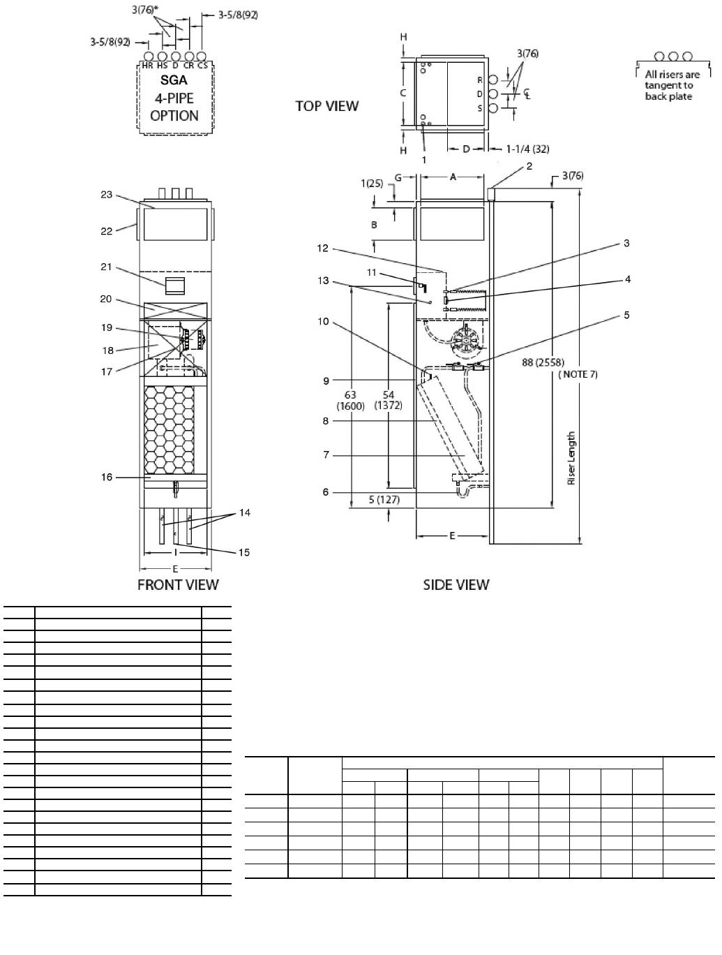
*Drawing provided for reference only. Dimensions may vary with options ordered.
NOTES:
1. Units are fabricated of 18-gage galvanized steel with a 16-gage galvanized fan deck.
2. All risers are insulated with 1/2-in. closed cell insulation.
3. Thermostats shipped loose for field connection.
4. Risers are piped to coil with valves as specified.
5. Blower, motor, valves, coil, and filter are accessible through the return air opening.
6. Unit and control box are insulated with 1/2-in. coated fiberglass insulation.
7. Riser length = [(floor to floor) +2 in.], maximum riser length = 115 inches.
8. Maximum riser size is 21/2-in. diameter. If larger sizes are required, please consult the factory.
9. Expansion loops in hot water heating circuits as required.
10. A 9-in. x 21/4-in. slot is provided in the inside back panel for coil connection penetration to permit expansion
and contraction of risers. Care must be taken to position the risers so that coil connection is at center of slot.
11. Drawing is pictorial (see unit arrangements for actual supply and return air orientation).
12. All dimensions are in inches.
†Unit weights are based on dry coils and minimum rows. Weights exclude packaging, valves, and other components.
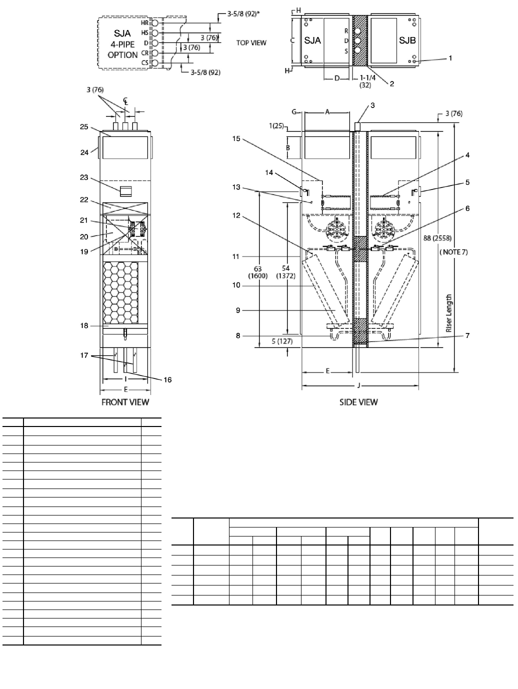
UNIT
SIZE
NOM
AIRFLOW
(cfm)
DIMENSIONS (in.) UNIT
WEIGHT†
(lb)
Single Supply Double Supply Top Supply EGH I
AB A BCD
03 300 14 8 14 6 14 10 17 11/211/214 180
04 400 14 12 14 6 14 10 17 11/211/214 225
06 600 18 10 18 6 16 12 20 1 2 18 240
08 800 18 12 18 6 16 12 20 1 2 18 260
10 1000 — — 22 8 18 16 24 1 3 22 280
12 1200 — — 22 8 18 16 24 1 3 22 305
A42-4125
LEGEND
CR — Cold Water Return
CS — Cold Water Supply
D— Drain
HR — Hot Water Return
HS — Hot Water Supply
R— Return
S—Supply
**Factory-Installed.
††Field-Installed.
ITEM DESCRIPTION QTY
1Electrical Knockouts 1
23-in. Expanded Section 3/5
3Strip Heater (Optional) 1
4Limit Switch**†† (Optional) 1
51/2-in. Isolation Ball Valves** 2/4
6Flexible Drain Tube/P-Trap 1
7Coil 1/2-in. OD Copper Tube 1
8Filter, Throwaway, 1-in.** 1
9Return Air Opening 1
10 Air Vent, Manual 1
11 Molex Connector for Field-Installed Stat 1
12 Control Box 1
13 Knockout (For Optional Remote Mounting) 2
14 Riser, Supply and Return (Copper) 2/4
15 Riser, Drain (Copper) 1
16 Drain Pan 1
17 Return Air Blockoff Panel (Optional) 1
18 Blower 1
19 Motor, 3-Speed, PSC, with Quick Connect 1
20 Access Panel (Control Box) 1
21 Control Opening (Surface Mount Stat) 1
22 Duct Collar, 1/2-in. Extension (Typical) 1/2/3
23 Supply Air Opening(s) 1/2/3
Fig. 28 — 42SG Furred-In Stack Dimensions
32
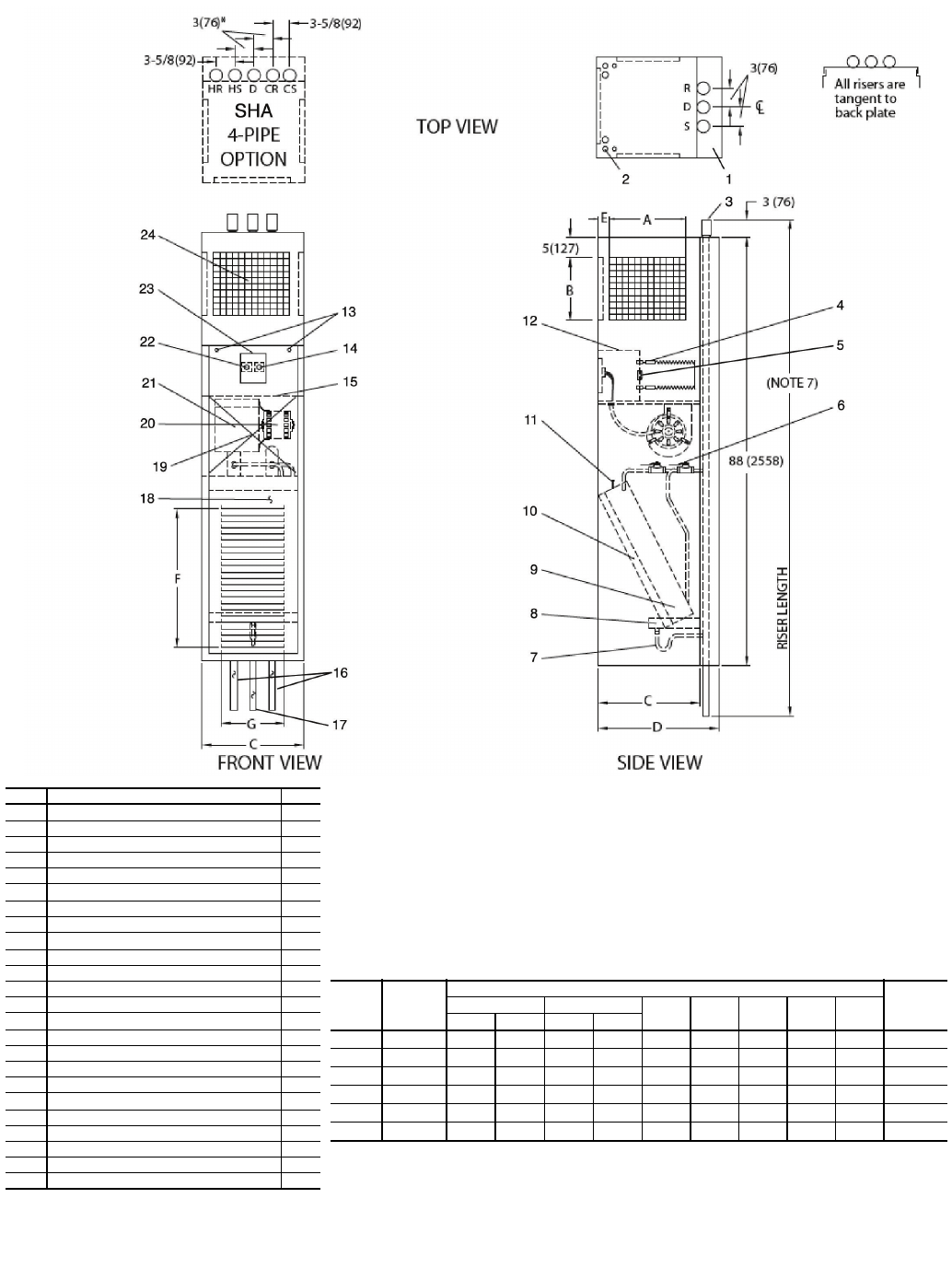
†Unit weights are based on dry coils and minimum rows. Weights exclude packaging, valves, and other components.
UNIT
SIZE
NOM
AIRFLOW
(cfm)
DIMENSIONS (in.) UNIT
WEIGHT†
(lb)
Single Supply Double Supply CDEFG
ABAB
03 300 14 8 14 6 17 223/811/2221/8143/4202
04 400 14 12 14 8 17 223/811/2221/8143/4247
06 600 14 12 14 8 20 253/8226
5/8173/4262
08 800 14 16 14 10 20 253/8226
5/8173/4286
10 1000 18 16 14 12 24 293/8331
1/8173/4311
12 1200 18 16 14 12 24 293/8331
1/8173/4336
*Drawing provided for reference only. Dimensions may vary with options ordered.
NOTES:
1. Units are fabricated of 18-gage galvanized steel with a 16-gage galvanized fan deck, painted with Arctic White.
2. 3-speed switch and thermostat are unit mounted.
3. Risers are piped to coil with valves as specified.
4. Blower, motor, valves, coil, and filter are accessible through the return air opening.
5. Unit is insulated with coated fiberglass.
6. Control box is insulated with 1/2-in. insulation for unit mounted controls.
7. Riser length = [(floor to floor) +2 in.], maximum riser length = 115 inches.
8. Maximum riser size is 21/2-in. diameter. If larger sizes are required, please consult the factory.
9. Expansion loops in hot water heating circuits as required.
10. A 9-in. x 21/4-in. slot is provided in the inside back panel for coil connection penetration to permit expansion and
contraction of risers. Care must be taken to position the risers so that coil connection is at center of slot.
11. Drawing is pictorial (see unit arrangements for actual supply and return air orientation).
12. 42SHA available in front return only.
13. All dimensions are in inches. A42-4126
**Factory-Installed.
††Field-Installed.
ITEM DESCRIPTION QTY
1Full Riser Chase 1
2Electrical Knockouts 1
33-in. Expansion Section 3/5
4Strip Heater (Optional) 1
5Limit Switch**†† (Optional) 1
61/2-in. Isolation Ball Valves** 2/4
7Flexible Drain Tube/P-Trap 1
8Drain Pan 1
9Coil 1/2-in. OD Tube 1
10 Filter, Throwaway, 1-in.** 1
11 Air Vent, Manual 1
12 Control Box 1
13 Cabinet Camloc® Fasteners 2
14 3-Speed Switch 1
15 Electrical Access Panel 1
16 Riser, Supply and Return (Copper) 2/4
17 Riser, Drain (Copper) 1
18 Return Air Panel 1
19 Return Air Blockoff Panel (Optional) 1
20 Motor, 3-Speed, PSC 1
21 Blower 1
22 Thermostat 1
23 Hinged Control Access Door 1
24 Double Deflection Steel Core Grille Assembly 1
LEGEND
CR — Cold Water Return
CS — Cold Water Supply
D— Drain
HR — Hot Water Return
HS — Hot Water Supply
R— Return
S—Supply
Fig. 29 — 42SH Cabinet Dimensions
33
†Unit weights are based on dry coils and minimum rows. Weights exclude packaging, valves, and other components.
UNIT
SIZE
NOM
AIRFLOW
(cfm)
DIMENSIONS (in.) UNIT
WEIGHT†
(lb)
Single Supply Double Supply Top Supply EG H I J
ABA BCD
03 300 14 8 14 6 14 10 17 11/211/214 401/4360
04 400 14 12 14 6 14 10 17 11/211/214 401/4450
06 600 18 10 18 6 16 12 20 1 2 18 461/4480
08 800 18 12 18 6 16 12 20 1 2 18 461/4520
10 1000 ——22 81816241 32254
1/4560
12 1200 ——22 81816241 32254
1/4610
*Drawing provided for reference only. Dimensions may vary with options ordered.
NOTES:
1. Units are fabricated of 18-gage galvanized steel with a 16-gage galvanized fan deck.
2. All risers are insulated with 1/2-in. closed cell insulation.
3. Thermostats shipped loose for field connection.
4. Risers are piped to coil with valves as specified.
5. Blower, motor, valves, coil, and filter are accessible through the return air opening.
6. Unit and control box are insulated with 1/2-in. coated fiberglass insulation.
7. Riser length = [(floor to floor) +2 in.], maximum riser length = 115 inches.
8. Maximum riser size is 21/2-in. diameter. If larger sizes are required, please consult the factory.
9. Expansion loops in hot water heating circuits as required.
10. A 9-in. x 21/4-in. slot is provided in the inside back panel for coil connection penetration to permit expansion
and contraction of risers. Care must be taken to position the risers so that coil connection is at center of slot.
11. Drawing is pictorial (see unit arrangements for actual supply and return air orientation).
12. All dimensions are in inches.
**Factory-Installed.
††Field-Installed.
ITEM DESCRIPTION QTY
1Electrical Knockouts 2
2Gypsum Board, 5/8-in. Type “X” 1
33-in. Expanded Section 3/5
4Strip Heater**(Optional) 2
5Limit Switch**†† (Optional) 2
61/2-in. Isolation Ball Valves** 4/8
7Thermafiber Insulation 2
8Flexible Drain Tube/P-Trap 2
9Coil 1/2-in. OD Copper Tube 2
10 Filter, Throwaway, 1-in.** 2
11 Return Air Opening 2
12 Air Vent, Manual 2
13 Knockout (For Optional Remote Mounting) 2
14 Molex Connector for Field Installed Stat 2
15 Control Box 2
16 Riser, Drain (Copper) 1
17 Riser, Supply and Return (Copper) 2/4
18 Drain Pan 2
19 Return Air Blockoff Panel (Optional) 1
20 Blower 2
21 Motor, 3-Speed, PSC, with Quick Connect 2
22 Access Panel (Control Box) 2
23 Control Opening (Surface Mount Stat) 2
24 Duct Collar, 1/2-in. Extension (Typical) 1/2/3
25 Supply Air Opening(s) 1/2/3
LEGEND
CR — Cold Water Return
CS — Cold Water Supply
D—Drain
HR — Hot Water Return
HS — Hot Water Supply
R—Return
S—Supply
A42-4127
Fig. 30 — 42SJ Back-to-Back Furred-In Stack Dimensions
34
*Drawing provided for reference only. Dimensions may vary with options ordered.
NOTES:
1. Units are fabricated of 18-gage galvanized steel with a 16-gage galvanized fan deck.
2. All risers are insulated with 1/2-in. closed cell insulation.
3. Thermostats shipped loose for field connection.
4. Risers are piped to coil with valves as specified.
5. Blower, motor, valves, coil, and filter are accessible through the return air opening.
6. Unit and control box are insulated with 1/2-in. coated fiberglass insulation.
7. Riser length = [(floor to floor) +2 in.], maximum riser length = 115 inches.
8. Maximum riser size is 21/2-in. diameter. If larger sizes are required, please consult the factory.
9. Expansion loops in hot water heating circuits as required.
10. A 9-in. x 21/4-in. slot is provided in the inside back panel for coil connection penetration to permit expansion
and contraction of risers. Care must be taken to position the risers so that coil connection is at center of slot.
11. Drawing is pictorial (see unit arrangements for actual supply and return air orientation).
12. All dimensions are in inches.
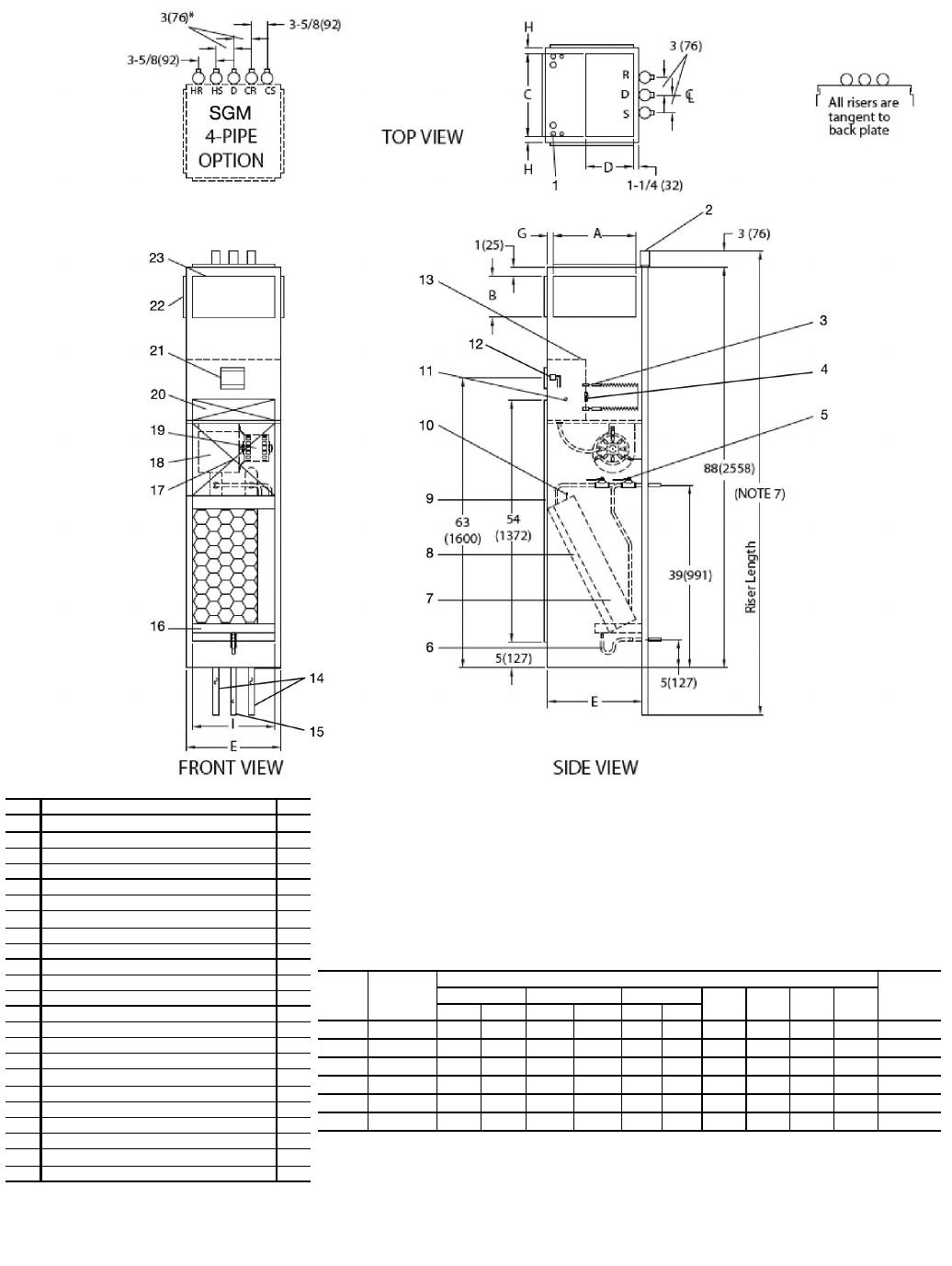
†Unit weights are based on dry coils and minimum rows. Weights exclude packaging, valves, and other components.
UNIT
SIZE
NOM
AIRFLOW
(cfm)
DIMENSIONS (in.) UNIT
WEIGHT†
(lb)
Single Supply Double Supply Top Supply EGH I
AB A BCD
03 300 14 8 14 6 14 10 17 11/211/214 180
04 400 14 12 14 6 14 10 17 11/211/214 225
06 600 18 10 18 6 16 12 20 1 2 18 240
08 800 18 12 18 6 16 12 20 1 2 18 260
10 1000 ——22 81816241 322 280
12 1200 ——22 81816241 322 305
A42-4128
**Factory-Installed.
††Field-Installed.
ITEM DESCRIPTION QTY
1Electrical Knockouts 1
23-in. Expanded Section 3/5
3Strip Heater** (Optional) 1
4Limit Switch**†† (Optional) 1
51/2-in. Isolation Ball Valves** 2/4
6Flexible Drain Tube/P-Trap 1
7Coil 1/2-in. OD Copper Tube 1
8Filter, Throwaway, 1-in.** 1
9Return Air Opening 1
10 Air Vent, Manual 1
11 Knockout (For Optional Remote Mounting) 2
12 Molex Connector for Field-Installed Thermostat 1
13 Control Box 1
14 Riser, Supply and Return (Copper) 2/4
15 Riser, Drain (Copper) 1
16 Drain Pan 1
17 Return Air Blockoff Panel (Optional) 1
18 Blower 1
19 Motor, 3-Speed, PSC, with Quick Connect 1
20 Access Panel (Control Box) 1
21 Control Opening (Surface Mount Thermostat) 1
22 Duct Collar, 1/2-in. Extension (Typical) 1/2/3
23 Supply Air Opening(s) 1/2/3
LEGEND
CR — Cold Water Return
CS — Cold Water Supply
D—Drain
HR — Hot Water Return
HS — Hot Water Supply
R—Return
S—Supply
Fig. 31 — 42SGM Furred-In Master Stack Dimensions
35
*Drawing provided for reference only. Dimensions may vary with options ordered.
NOTES:
1. Units are fabricated of 18-gage galvanized steel with a 16-gage galvanized fan deck.
2. All risers are insulated with 1/2-in. closed cell insulation.
3. Thermostats shipped loose for field connection.
4. Risers are piped to coil with valves as specified.
5. Blower, motor, valves, coil, and filter are accessible through the return air opening.
6. Unit and control box are insulated with 1/2-in. coated fiberglass insulation.
7. Riser length = [(floor to floor) +2 in.], maximum riser length = 115 inches.
8. Maximum riser size is 21/2-in. diameter. If larger sizes are required, please consult the factory.
9. Expansion loops in hot water heating circuits as required.
10. A 9-in. x 21/4-in. slot is provided in the inside back panel for coil connection penetration to permit expansion
and contraction of risers. Care must be taken to position the risers so that coil connection is at center of slot.
11. Drawing is pictorial (see unit arrangements for actual supply and return air orientation).
12. All dimensions are in inches.
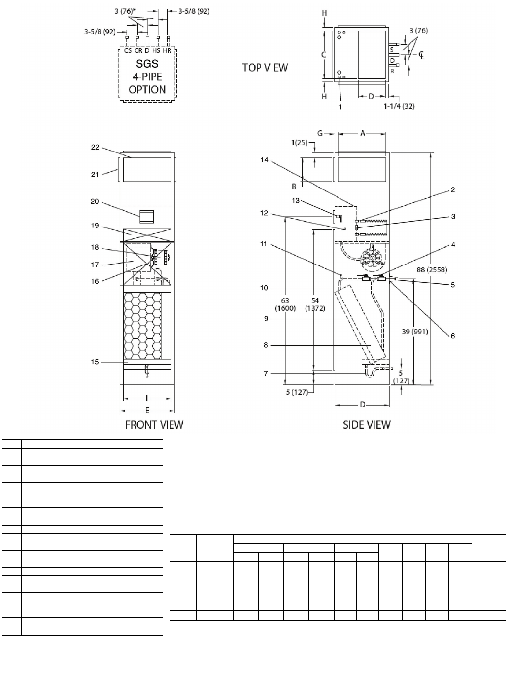
†Unit weights are based on dry coils and minimum rows. Weights exclude packaging, valves, and other components.
UNIT
SIZE
NOM
AIRFLOW
(cfm)
DIMENSIONS (in.) UNIT
WEIGHT†
(lb)
Single Supply Double Supply Top Supply EGH I
ABABCD
03 300 14 8 14 6 14 10 17 11/211/214 162
04 400 14 12 14 6 14 10 17 11/211/214 203
06 600 18 10 18 6 16 12 20 1 2 18 216
08 800 18 12 18 6 16 12 20 1 2 18 234
10 1000 — — 22 8 18 16 24 1 3 22 252
12 1200 — — 22 8 18 16 24 1 3 22 275
A42-4129
**Factory-Installed.
††Field-Installed.
ITEM DESCRIPTION QTY
1Electrical Knockouts 1
2Strip Heater** (Optional) 1
3Limit Switch**†† (Optional) 1
41/2-in. Isolation Ball Valves** 2/4
5Coil Stub Outs 2/4
6Shipping Brace 2/4
7Flexible Drain Tube/P-Trap 1
8Coil 1/2-in. OD Copper Tube 1
9Filter, Throwaway, 1-in.** 1
10 Return Air Opening 1
11 Air Vent, Manual 1
12 Knockout (For Optional Remote Mounting) 2
13 Molex Connector for Field-Installed Stat 1
14 Control Box 1
15 Drain Pan 1
16 Return Air Blockoff Panel (Optional) 1
17 Blower 1
18 Motor, 3-Speed, PSC, with Quick Connect 1
19 Access Panel (Control Box) 1
20 Control Opening (Surface Mount Thermostat) 1
21 Duct Collar, 1/2-in. Extension (Typical) 1/2/3
22 Supply Air Opening(s) 1/2/3
LEGEND
CR — Cold Water Return
CS — Cold Water Supply
D—Drain
HR — Hot Water Return
HS — Hot Water Supply
R—Return
S—Supply
Fig. 32 — 42SGS Furred-In Slave Stack Dimensions

36
Fig. 33 — 42SU Universal Furred-In Stack Dimensions
*Unit weights are based on dry coils and minimum rows. Weights exclude packaging, valves, and other components.
UNIT
SIZE
UNIT
WEIGHT* lb
(kg)
DIMENSIONS, in. (mm)
FILTER SIZE
in. (mm)
Side Supply Top Supply
AB Size CD Size EFH I
03 360 (163) 14 (356) 12 (305) 14 x 12
(356 x 305) 14 (356) 10 (254) 14 x 10
(356 x 254) 17 (432) 3 (76) 11/2 (38) 14 (356) 121/2 x 241/4 x 1
(318 x 616 x 25)
04 450 (204)
06 480 (218) 18 (457) 12 (305) 18 x 12
(457 x 305) 16 (406) 12 (305) 16 x 12
(406 x 305) 20 (508) 1 (25) 2 (51) 18 (457) 161/4 x 263/4 x 1
(413 x 679 x 25)
08 520 (236)
10 560 (254) 22 (559) 16 (406) 22 x 16
(559 x 406) 18 (457) 16 (406) 18 x 16
(457 x 406) 24 (610) 1 (25) 3 (76) 22 (559) 201/2 x 291/4 x 1
(521 x 743 x 25)
12 610 (277)
8
(203)
51
(1295)
I
E
19
8
14
23 15
22
10
11
9
3
5
2
E
63
(1600)
21
12
13
17
7
6
16
A
B
FC
L
39
(991)
5
(127)
1-1/4
(32)
4
(102)
5
(127)
88
(2235)
H
R
H
S
C
R
C
S
D
1-1/4
(32)
HCH
HR CR CSHS D
3-5/8
(92)
3-5/8
(92)
3
(76)
3
(76)
4
1-1/4
(32)
20
18
1
NOTES:
1. Units are fabricated of 18-gage galvanized steel with a 16-gage galvanized fan deck.
2. Thermostats shipped loose for field connection.
3. Blower, motor, valves, coil, and filter are accessible through the return air opening.
4. Unit and control box are insulated with 1/2-in. (13 mm) coated fiberglass insulation.
5. All risers will ship separately from units. Riser dimensions are measured from centerline of knockout.
6. Drain knockouts on three sides of cabinet.
7. Flex hoses ship with unit.
8. Thread fittings on both ends of flex hoses must be field tightened and leak tested.
9. Return air panel not shown.
10. All dimensions are in inches (mm).
LEGEND
CR — Cold Water Return
CS — Cold Water Supply
D—Drain
HR — Hot Water Return
HS — Hot Water Supply
PSC — Permanent Split Capacitor
SWT — Sweat
Item Description Qty
1Float Switch (Optional) 1
2Drain Pan 1
3Flexible Drain Tube/P-Trap 1
4Drain Knockout (3 Sides) 1 each
side
5Blower 1
6Riser Knockouts (3 Sides) 2/4
71/2 in. Flare Adaptor (SWT x 37.5) 2/4
8Coil, 1/2 in. OD Copper Tube 1
91 in. Throwaway Filter
(Factory Installed) 1
10 Manual Air Vent 1
11 Return Air Opening 1
12 Knockout (For Optional Thermostat
Remote Mounting) 3
13 Molex Connector for Field-Installed
Thermostat 1
14 Control Box 1
15 Duct Collar Extension
(1/2 in. Side, 1 in. Top) 1/2/3
16 Outside Air Knockout
(On Each Side Panel) 1
17 Electrical Knockouts
(Near Each Side) 1
18 Service Switch (Optional) 1
19 Motor, 3-Speed, PSC, with Quick
Connect 1
20 Coil Blockoff Plate 1
21 Access Panel (Control Box) 1
22 Control Opening Knockout
(Surface Mount Thermostat) 1
23 Supply Air Openings
(4 Sides and Top, Stitch Cut) 1/2/3
a42-4154
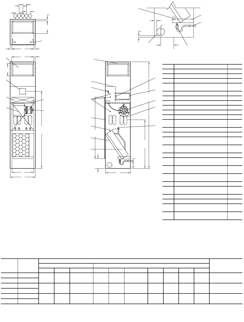
37
Fig. 34 — 42SU Universal Furred-In Stack with Heater Dimensions
*Unit weights are based on dry coils and minimum rows. Weights exclude packaging, valves, and other components.
UNIT
SIZE
UNIT
WEIGHT*
lb (kg)
DIMENSIONS, in. (mm) FILTER SIZE
in. (mm)
Side Supply Top Supply
AB Size CD Size EFH I
03 360 (163) 14 (356) 12 (305) 14 x 12
(356 x 305) 14 (356) 10 (254) 14 x 10
(356 x 254) 17 (432) 3 (76) 11/2 (38) 14 (356) 121/2 x 241/4 x 1
(318 x 616 x 25)
04 450 (204)
06 480 (218) 18 (457) 12 (305) 18 x 12
(457 x 305) 16 (406) 12 (305) 16 x 12
(406 x 305) 20 (508) 1 (25) 2 (51) 18 (457) 161/4 x 263/4 x 1
(413 x 679 x 25)
08 520 (236)
10 560 (254) 22 (559) 16 (406) 22 x 16
(559 x 406) 18 (457) 16 (406) 18 x 16
(457 x 406) 24 (610) 1 (25) 3 (76) 22 (559) 201/2 x 291/4 x 1
(521 x 743 x 25)
12 610 (277)
NOTES:
1. Units are fabricated of 18-gage galvanized steel with a 16-gage galvanized fan deck.
2. Thermostats shipped loose for field connection.
3. Blower, motor, valves, coil, and filter are accessible through the return air opening.
4. Unit and control box are insulated with 1/2-in. (13 mm) coated fiberglass insulation.
5. All risers will ship separately from units. Riser dimensions are measured from centerline of
knockout.
6. Drain knockouts on three sides of cabinet.
7. Flex hoses ship with unit.
8. Thread fittings on both ends of flex hoses must be field tightened and leak tested.
9. Return air panel not shown.
10. All dimensions are in inches (mm).
LEGEND
CR — Cold Water Return
CS — Cold Water Supply
D—Drain
HR — Hot Water Return
HS — Hot Water Supply
PSC — Permanent Split Capacitor
SWT — Sweat
6
5
8
(203)
51
(1295)
I
E
21
10
16
25 17
24
12
13
11
3
7
2
E
63
(1600)
23 14
15
19
9
8
18
A
B
F
C
L
39
(991)
5
(127)
1-1/4
(32)
4
(102)
5
(127)
88
(2235)
H
R
H
S
C
R
C
S
D
1-1/4
(32)
HCH
HR CR CSHS D
3-5/8
(92)
3-5/8
(92)
3
(76)
3
(76)
4
1-1/4
(32)
1
22
20
Item Description Qty
1Float Switch (Optional) 1
2Drain Pan 1
3Flexible Drain Tube/P-Trap 1
4Drain Knockout (3 Sides) 1 each
side
5Limit Switch (Factory Installed) 1
6Strip Heater 1
7Blower 1
8Riser Knockouts (3 Sides) 2/4
91/2 in. Flare Adaptor (SWT x 37.5) 2/4
10 Coil, 1/2 in. OD Copper Tube 1
11 1 in. Throwaway Filter
(Factory Installed) 1
12 Manual Air Vent 1
13 Return Air Opening 1
14 Knockout (For Optional
Thermostat Remote Mounting) 3
15 Molex Connector for
Field-Installed Thermostat 1
16 Control Box 1
17 Duct Collar Extension
(1/2 in. Side, 1 in. Top) 1/2/3
18 Outside Air Knockout
(On Each Side Panel) 1
19 Electrical Knockouts
(Near Each Side) 1
20 Service Switch (Optional) 1
21 Motor, 3-Speed, PSC,
with Quick Connect 1
22 Coil Blockoff Plate 1
23 Access Panel (Control Box) 1
24 Control Opening Knockout
(Surface Mount Thermostat) 1
25 Supply Air Openings
(4 Sides and Top, Stitch Cut) 1/2/3
a42-4155
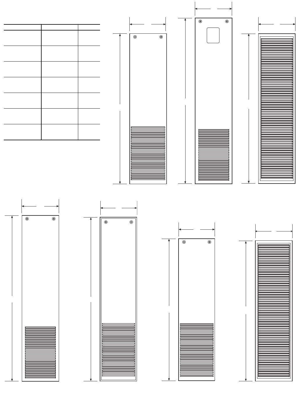
38
Fig. 35 — Return-Air Wall Panels for Furred-In Units — Panels with No Frame
PANEL DIMENSIONS (in.)
NOTE: Dimensions in inches.
PANEL NO. UNIT SIZE A
1
03, 04 15.5
06, 08 19.5
10, 12 23.5
2
03, 04 15.5
06, 08 19.5
10, 12 23.5
3
03, 04 15.2
06, 08 19.2
10, 12 23.2
6
03, 04 15.5
06, 08 19.5
10, 12 23.5
7
03, 04 15.1
06, 08 19.1
10, 12 23.1
8
03, 04 15.5
06, 08 19.5
10, 12 23.5
10
03, 04 15.2
06, 08 19.2
10, 12 23.2
PANEL NO. 1
55.5
A
a42-4167
PANEL NO. 2
61.1
A
a42-4169
PANEL NO. 6
61.1
A
A42-4171
PANEL NO. 7
60.4
A
A42-4172
PANEL NO. 3
55.3
A
A42-4173
PANEL NO. 8
52.5
A
A42-4160
PANEL NO. 10
52.3
A
A42-4162
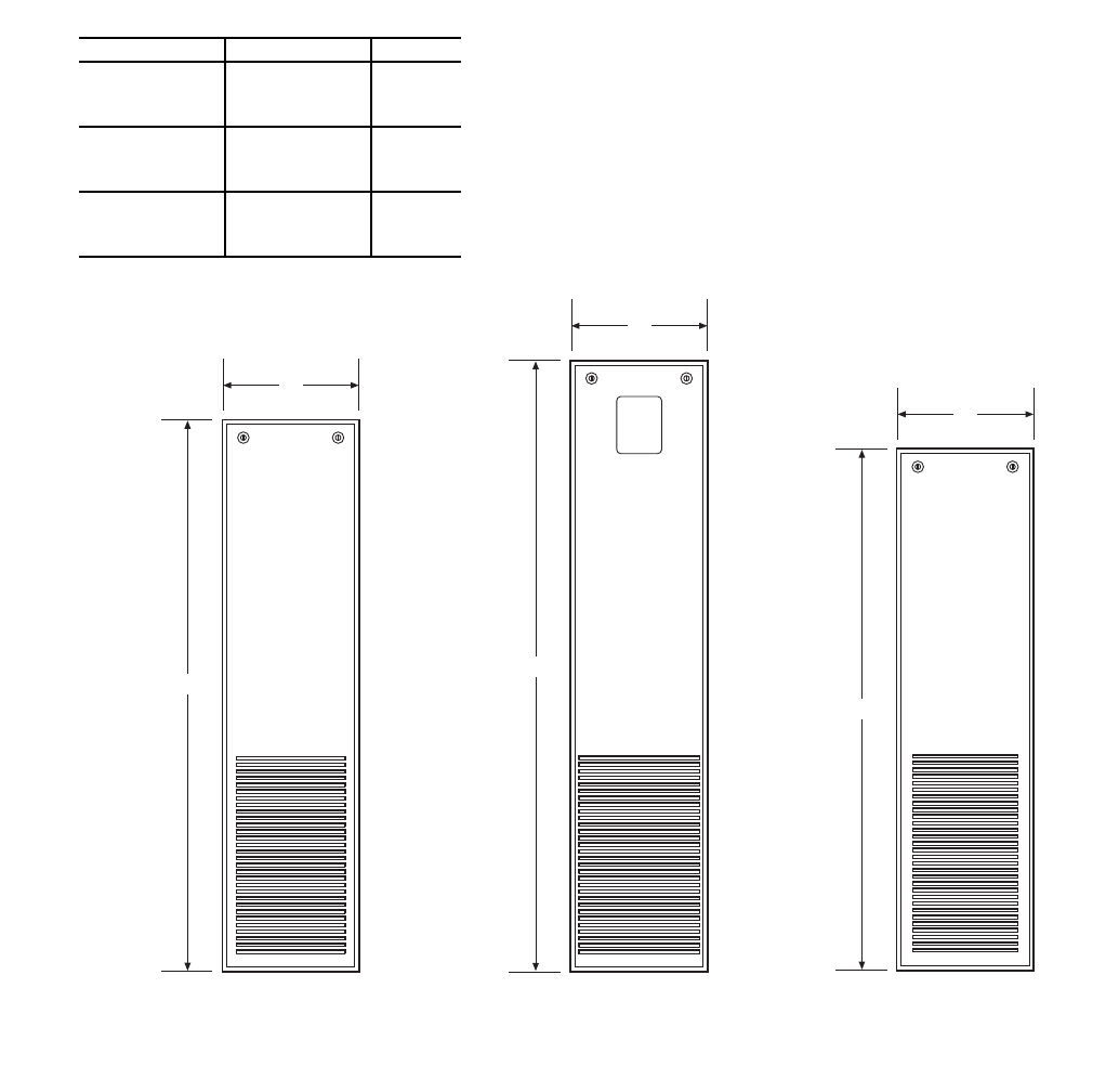
39
Fig. 36 — Return-Air Wall Panels for Furred-In Units — Panels with Frame
PANEL AND FRAME DIMENSIONS (in.)
NOTE: Dimensions in inches.
PANEL NO. UNIT SIZE A
4
03, 04 15.1
06, 08 19.1
10, 12 23.1
5
03, 04 15.1
06, 08 19.1
10, 12 23.1
9
03, 04 15.1
06, 08 19.1
10, 12 23.1
PANEL NO. 4
54.7
A
A42-4168
PANEL NO. 5
60.4
A
A42-4170
PANEL NO. 9
51.7
A
A42-4161
40
INSTALLATION
Step 1 — Place Units in Position
42C UNITS
1. Select the unit location. Allow adequate space for free air
circulation, service clearances, piping and electrical
connections, and any necessary ductwork. For specific
unit dimensions, refer to Fig. 1-14. Allow clearances ac-
cording to local and national electric codes.
2. Make sure ceiling is able to support the weight of the unit.
See Table 1 for nominal unit weight.
3. Ensure bottom panel has been removed from 42CG, CK
units with mounting holes. When unit is lifted, access to
the 0.375-in. mounting holes is through the bottom of the
unit. Hanger rods and fasteners and other required hard-
ware must be field-supplied.
4. Move unit into position. Ensure unit is level or pitched
towards drain to ensure proper drainage and operation.
Pitch of suspended unit can change after coil is filled;
recheck after filling coil.
5. Mounting unit:
a. Use rods and fasteners to suspend the unit at the
factory-provided mounting holes with rubber
grommets on the top of the unit on 42CG, CK
units. Reach into unit and attach unit to the ceiling
using the 0.375-in. mounting holes (4) in top
panel; do not use any other locations.
b. Use rods and fasteners to suspend the unit at the
factory-provided 0.375-in. hanger slots (4) with
rubber grommets on the top of the unit on the
42CA, CE, and CF units.
NOTE: The four mounting holes and hanger slots
with rubber grommets are NOT for balancing unit.
6. 42CA and 42CF units without plenums and 42CE and CF
with bottom inlet may be installed in noncombustible
areas only.
NOTE: The installation of horizontal concealed units must
meet the requirements of the National Fire Protection Associa-
tion (NFPA) Standard 90A or 90B concerning the use of con-
cealed ceiling space as return-air plenums.
42V UNITS
1. Select the unit location. Allow adequate space for free air
circulation, service clearances, piping and electrical
connections, and any necessary ductwork. For specific
unit dimensions, refer to the submittals. Allow clearances
according to local and national electric codes.
2. Make sure the floor is able to support the weight of the
unit. See Table 2 for nominal unit weight.
3. Ensure wall behind unit is smooth and plumb; if
necessary, install furring strips on walls with irregular
surfaces or mullions. Furring strips must be positioned
behind mounting holes in unit (42VA, VB, VF units).
Fasteners, furring strips, and other seals (if required) must
be field-supplied.
4. Remove all wall and floor moldings from behind the unit.
5. Ensure 42VA top panel (under window application) and
42VB, VF front panel has been removed from unit to
obtain access to the four 0.75-in. mounting holes. Hanger
rods and fasteners and other required hardware must be
field-supplied.
6. Move unit into position. Ensure unit is level or pitched
towards drain to ensure proper drainage and operation.
Pitch of suspended unit can change after coil is filled;
recheck after filling coil.
7. Adjust 42VA, VB, VC, VE, VF units leveling legs so unit
is level. Unit must be level for proper operation and
condensate drainage.
8. Mounting unit:
a. Use rods and fasteners to suspend the unit at the
factory-provided mounting holes with rubber
grommets on the top of the unit on 42VA, VB, VF
units. Reach into unit and attach unit to the wall
using the 0.375-in. mounting holes (4) in top
panel; do not use any other locations. The four
mounting holes and hanger slots with rubber
grommets are NOT for balancing unit.
b. On 42VG unit ensure unit is placed snug within
the wall.
c. On 42VC, VE unit ensure unit is flushed against
the wall.
NOTE: For any unit without a return-air duct connection,
applicable installation codes may limit unit to installation in
single story residence only.
42D UNITS
1. Select the unit location. Allow adequate space for free air
circulation, service clearances, piping and electrical con-
nections, and any necessary ductwork. For specific unit
dimensions, refer to the submittal drawings. Allow clear-
ances according to the local and national electrical codes.
2. Be sure either the ceiling (42DA, DC, DE, and DF units)
or floor (42DD unit) is able to support the weight of the
unit. See Table 3 for nominal unit weight.
3. Move unit into position. Ensure unit is level or pitched
towards drain to ensure proper drainage and operation.
See Fig. 23-27. Pitch of suspended unit can change after
coil is filled; recheck after filling coil.
4. Mounting units to the ceiling:
a. When unit is lifted, access to the 0.375-in. mount-
ing holes is on the top panel of the unit. Hanger
rods and fasteners and other required hardware
must be field-supplied.
b. Use rods and fasteners to suspend the unit at the
factory-provided mounting holes with rubber
grommets on the top of the unit. Attach unit to the
ceiling using the 0.375-in mounting holes (4) in
top panel; do not use any other locations.
c. Use the rods and fasteners to suspend the unit at
the factory-provided 0.375-in. hanger slots (4)
with the rubber grommets on the top of the unit on
the 42DA, DC, DE, and DF units.
NOTE: The four mounting holes and hanger slots
with rubber grommets are NOT for balancing unit.
d. Models 42DA and 42DC with bottom inlet may be
installed in noncombustible return spaces only.
5. Mounting units on the floor:
a. Ensure wall behind the unit is smooth and plumb;
if necessary, install furring strips on walls with
irregular surfaces or mullions. Furring strips must
be positioned behind mounting holes on 42DD
units. Fasteners, furring strips, and other seals (if
required) must be field-supplied.
b. If the unit has leveling legs, adjust them correctly
to level the unit.
6. Protect units from damage caused by jobsite debris. Do
not allow foreign material to fall in unit drain pan.
Prevent dust and debris from being deposited on motor or
fan wheels.
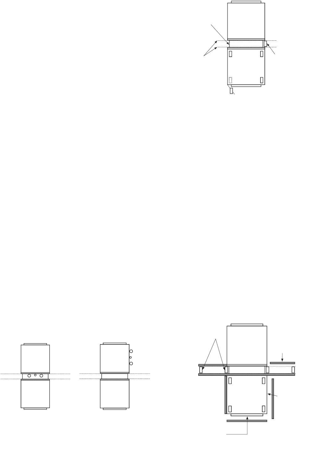
41
42S UNITS — A factory tag is on top of each unit. Tag states
riser tier number, floor, room number if furnished and supply-
air arrangement. Check unit for any other labels that apply to
installation. Remove unit from pallet and take directly to
assigned space for installation. Great care must be taken to
assure that no force or pressure be applied to the coil, risers or
piping during handling. Never use the riser to lift the unit. To
maintain the straight and square cabinet alignment, avoid lift-
ing or supporting the cabinet only at the top and bottom.
1. Begin on lowest floor and progress upward, floor by
floor, to top.
2. Examine drain line (Fig. 28-34). Be sure both ends are in
place and that it forms a trap. Avoid pinching drain line.
3. Tip unit over riser hole in building floor. As unit is
righted, align riser with unit below.
NOTE: The unit must be lowered into the space taking
care to properly align the risers to engage the riser swaged
section on the unit below. The riser should never be bent
or pushed together to be passed through the floor slot and
should never be lifted up or pulled down to meet the riser
on the floor below or above.
4. Install isolator pads beneath the four corners of unit if
applicable.
5. Before anchoring the equipment in place, the unit must be
leveled and the cabinet must be squared and brought into
line with any adjacent or included walls. The unit may be
anchored in place by bolting directly through the unit
floor or attaching to the cabinet in some location that will
not interfere with drywall or other items such as the sup-
ply grille, thermostat, or return access panel. When at-
taching to the unit cabinet, care must be taken to not pen-
etrate the cabinet in locations that may damage internal
components or wiring. The mounting technique is a mat-
ter of choice; however, the unit should always be an-
chored securely to prevent movement during construction
and riser expansion and contraction. On certain units,
shipping screws or braces must be removed after the unit
is installed. Be sure to check all tags on the unit to deter-
mine which, if any, of these devices need to be removed.
6. If installing a 42SJ unit, follow Steps a-h. For all other
42S units, continue to Step 7.
NOTE: The 42SJ back-to-back fan coils have been de-
signed to serve two separate rooms. These products are
classified by Underwriters Laboratories Inc. for use in
penetration firestop systems, control number 27WL when
ordered with 1-hr rated chase. See UL Fire Resistance
Directory for more information. Figure 37 shows the
42SJ unit with standard risers and with Siamese risers.
a. Lay out the control lines for the drywall track and
studs in the floor and ceiling (see Fig. 38).
NOTE: Tracking may be installed now or after the
unit is set.
b. Position the 42SJ fan coil assembly between two
rooms with the unit drywall separation spotted
over the wall control lines.
c. If not already installed, install the floor and ceiling
tracks up to and over the 42SJ fan coil unit.
d. Position the vertical studs and fasten into each of
the stud pockets formed into the chase side panels
(see Fig. 38).
NOTE: The studs may be mechanically fastened
to the 42SJ fan coil. Care should be taken, how-
ever, not to penetrate the supply or return water
risers or internal piping. Given the levelness of the
floor and/or the fan coil assembly, some shimming
may be necessary.
e. Assemble the specified wall construction up to
and over the top of the fan coil unit (see Fig. 39).
f. With the fire-wall separation being complete, the
drywall skin on the surface of the individual fan
coils can be applied. Drywall can be applied
directly to the surface, or, if necessary, studding
may be installed on the corners for vertical control
(see Fig. 39).
g. For ease of installation of the access panel, apply
drywall on the return air side directly to the sur-
face of the unit (see Fig. 39). When applying the
wall board directly to the unit cabinet, it may be
necessary to shim the wall board in some areas to
achieve the desired finished wall surface.
42SJB
42SJA
42SJB
42SJA
Fig. 37 — 42SJ Unit with Standard and Siamese
Risers
INSTALL WALL
STUD INTO
POCKET
FORMED BY
CHASE SIDE
PANEL
CHASE
SIDE
PANEL
DRYWALL
TRACK AND
STUD
CONTROL
LINES
INSTALL STUDS FROM TOP OF
UNIT TO CEILING (4 CORNERS)
Fig. 38 — 42SJ Unit as Shipped
WALL STUDS
INSTALL WALL
GYPSUM
BOARD
(TO WALL AND
OVER TOP OF
UNIT)
INSTALL
GYPSUM
BOARD TO
UNIT SIDES
INSTALL
GYPSUM
BOARD TO
FACE OF
UNIT WITH
CUT OUTS
FOR SUPPLY,
RETURN AND
THERMOSTAT
Fig. 39 — 42SJ Unit Installation
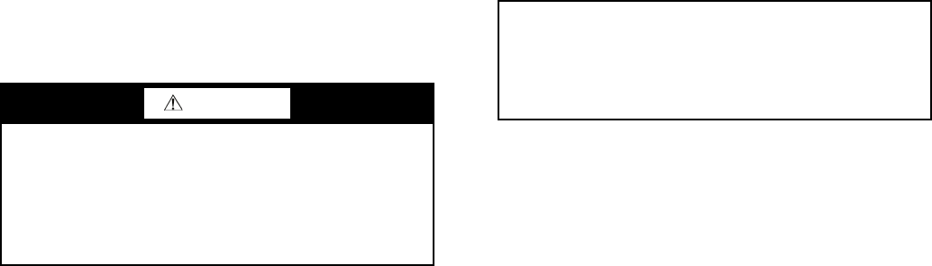
42
h. After all drywalling and painting is complete,
install thermostats, supply air grilles and return air
panels.
7. Attach unit risers:
NOTE: The supply and return connections are marked on
the coil stub-outs and the valve package with an “S”
meaning supply or inlet and “R” meaning return or outlet
indicating flow direction to and from the coil. Blue letters
mark the chilled water connections and red letters mark
the hot water connections.
a. Each riser has a 3-in. swaged portion at top and
sufficient extension at bottom for an inserted
length of approximately 2-in. This unit-to-unit
joint is NOT intended for full bottoming in the
joint, but allows for variations in floor-to-floor
dimensions and for correct riser positioning.
If job requires that unit risers be supplemented
with between-the-floor extensions pieces may be
field-supplied or factory-supplied. If factory-
supplied, insulation is also provided.
b. Level unit to ensure proper coil operation and
condensate drainage. Proper riser installation and
vertical positioning in the unit provides for a unit
piping run-out to the service valves which are cen-
tered in the access slots and level or sloping down
slightly away from the riser. This prevents con-
densation from running back to the riser and pos-
sible damage from dripping at the bottom of a
riser column. After units are positioned and riser
centered in pipe chase, make unit plumb in two
directions, using unit frame as a reference.
c. Anchor unit to building. Use bolts or lag screws
through holes provided in unit frame.
d. After all units in a stack are anchored, make unit-
to-unit riser joints. First, center each coil-to-riser
line within the expansion slot in the unit back
panel. Each riser joint must be in vertical
alignment with at least 1-in. penetration into the
swaged joint. This condition is met if floor-to-
floor dimension is as specified and coil-to-riser
lines are properly centered. Wide variations in
floor-to-floor dimensions may necessitate cutting
off or extending individual risers. Such modifica-
tions are the full responsibility of the installing
contractor.
e. Before making the riser joints, the riser insulation
must be pulled back away from the joint and pro-
tected from heat during the soldering process. Sol-
der riser joints with phos-copper, silfos, or other
high temperature alloy. The riser joint filler mate-
rial must be selected to withstand the total operat-
ing pressure (both static and pumping head) to
which the system will be subjected. Soft solder
(50-50, 60-40, or 85-15) or other low temperature
lead alloy is not suitable for this application.
8. Anchor risers as required:
a. Do not fasten risers rigidly within each unit.
Risers must be free to move within pipe chase
in response to normal vertical expansion and
contraction.
b. Built in risers must be anchored at some point
to building structure. Unit design accommodates
up to 11/2-in. expansion and contraction in riser
assemblies when positioned properly at the job
site. Risers must be anchored to the building struc-
ture to limit expansion and contraction movement
to a maximum of 11/2-inches. Riser anchoring and
expansion compensation is not included in the fac-
tory-supplied unit and must be provided.
9. Test the system for leaks after the connections are com-
pleted. When testing with air or some other gas, it might
be necessary to tighten stem packing nuts on some valves
to maintain air pressure in the riser. Pressure testing risers
with water should be done with the unit service valves
closed to prevent flushing debris into the unit valve pack-
ages. This will also allow risers to be drained down after
testing in the winter to avoid freeze-up problems.
10. After system integrity has been established, pull the riser
insulation back into place over the joint and glue or seal
to prevent sweating and heat loss or gain. Internal chilled
water piping and valves are located over the drain pan
and need not be insulated.
11. If required, fireproof were necessary. Any fireproofing re-
quirements where risers or piping penetrate floors or
walls are the responsibility of the installer. This work
should be done only after all pressure testing is complet-
ed. The fireproofing method used must accommodate
pipe expansion and contraction and the piping must be
protected from abrasion and chemical attack. The pipe in-
sulation also must be maintained to prevent sweating and
must be protected from wear or erosion at the joint be-
tween the insulation and the fireproofing material.
Step 2 — Make Piping Connections — Access to
piping is available through the access panels at the side of the
units or front of the unit. Qualified personnel in accordance
with local and national codes must perform all piping connec-
tions. Refer to Tables 1-4 for piping connections.
NOTE: It is important to have a common understanding of
which side of the unit is the right hand side and which is the
left hand side.
When facing the supply air outlet from the front of the unit
(air blowing in your face), your right hand will be on the right
side of the unit and your left hand will be on the left side of the
unit. See Fig. 40. Refer to Fig. 41 and 42 for typical piping
connections.
The supply and return piping connections of the factory-
provided valve package are either swaged for field brazing
(standard) or union fitted (optional) for field connection to the
coil.
CAUTION
Toxic residues and loose particles resulting from manufac-
turing and field piping techniques such as joint compounds,
soldering flux, and metal shavings may be present in the
unit and the piping system. Special consideration must be
given to system cleanliness when connecting to solar,
domestic or portable water systems. Failure to heed this
warning could result in equipment damage.
IMPORTANT: Chilled water and hot water risers should
never be piped to drain down into the condensate riser.
Extensive water damage can occur due to drain over-
flow. Drain chilled and hot water risers to a remote loca-
tion away from the unit such as sink, room and floor
drains.
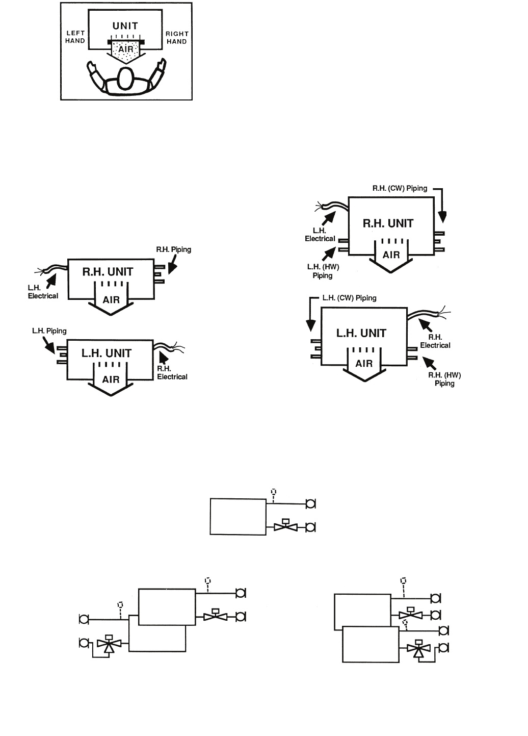
43
VALVE PACKAGES — There are limitations on physical
size of pneumatic valves, quantity and type of matching
components, and required control interface. See Fig. 43.
Consult factory before ordering any special valve package
components that are not covered in this book.
Valve packages are shipped with the units or in unit cartons.
Valve packages include belled ends for field soldering to coil
connections.
All factory-furnished cooling valve packages are arranged
to position as much of the package as possible over an auxiliary
drain pan or drip lip. This helps minimize field piping insula-
tion requirements. Refer to Fig. 44-47 for pipe connection
configurations. See Table 5 for descriptions of common piping
components.
Fig. 40 — Unit End Reference
NOTE: Chilled water piping determines the hand of the unit.
Fig. 41 — Pipe Connection Configurations
NOTE: Chilled water piping determines the hand of the unit.
SAME END CONNECTION OPPOSITE END CONNECTION
Valve Packages For 2-Pipe Systems — Valve packages for standard 2-pipe units are piped for same end
connection (L.H. or R.H.).
Valve Packages for 4-Pipe Systems — Select 2 valve packages per unit.
NOTE: Hot water valve package requirements may not be the same as chilled water valve package!
LEGEND
CW — Chilled Water
HW — Hot Water
LH — Left Hand
RH — Right Hand
SAME END CONNECTION
OPPOSITE END CONNECTION
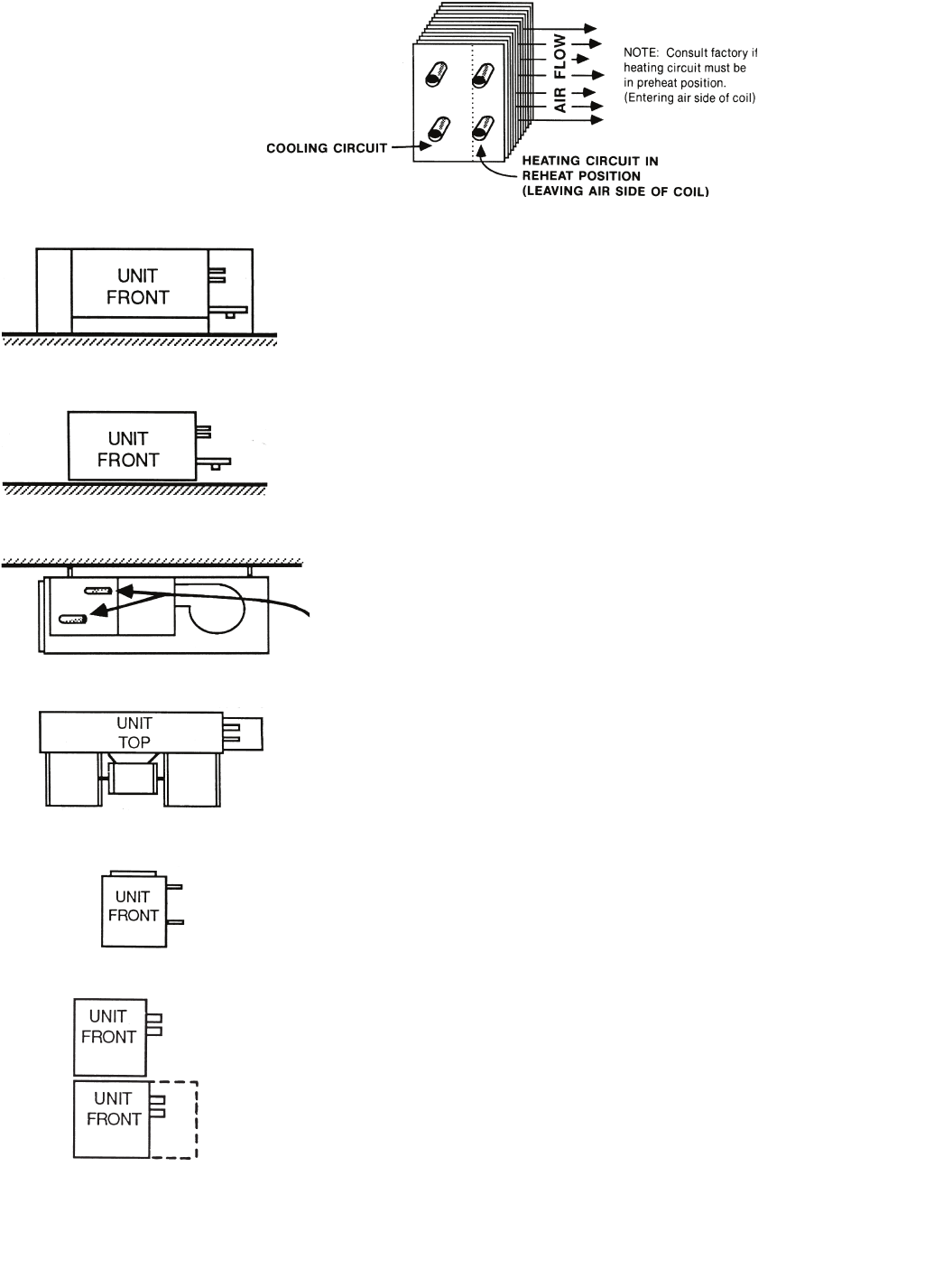
44
Fig. 42 — Piping Connection Positions
Hydronic Coil Arrangement
Field Piping Connections*
VERTICAL FLOOR UNITS — 42VB, VE, VF
Pipe into cabinet end compartment (opening in bottom and
back).
VERTICAL FLOOR UNITS — 42VA, VC
Pipe to external connections (no cabinet).
CEILING UNITS (EXPOSED) — 42CG, CK, DE, DF
Pipe through knock-outs in rear of cabinet to coil and valve
package connections.
CEILING UNITS (CONCEALED) — 42CA, CE, CF, DA, DC
Pipe to connections extending from end of unit.
VERTICAL UNITS — 42DD
Pipe to stub connections extending from side of unit.
WALL UNITS, FURRED-IN
Pipe to stub connections at the side of unit.
or into optional piping compartment. Optional piping compart-
ment is required if valves are factory installed. Factory-installed
valve package is limited to one 2-way or 3-way motorized valve
and 2 hand valves.
*Location of field piping connections will vary depending on number of coil rows on factory-supplied coil or
arrangement of factory-supplied valves.
42VG
42VG
a42-4177
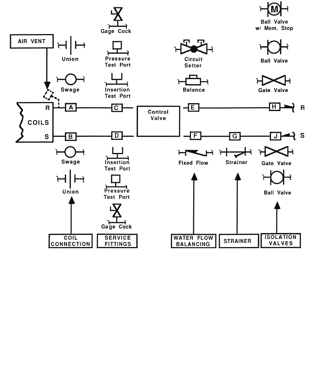
45
Fig. 43 — Symbols and Placement of Valves
Coil Connections (Positions A & B) — When isolation valve only is added to supply or return line, the isolation valve will
be factory brazed to the coil stub-out. Addition of any other component or connection to the supply or return line will change
the respective coil connection(s).
Service Fittings (Positions C & D) — Optional fittings for attaching pressure/temperature sensing devices to obtain pres-
sure drop or temperature differential across coil. Used with ball valve or balance valve where extremely accurate water flow
balancing is required.
Water Flow Balancing (Positions E, F, & H) — Only one device per total valve package to be used for balancing water
flow through the coil. When isolation valve (ball valve or ball valve with memory stop at position H) is used for water flow bal-
ancing, do not specify additional balancing device at position E or F. When balancing device is specified at position E or F,
isolation valve does not require balancing feature at position H (with a 3-way motorized valve, a bypass balancing valve
may be specified in the bypass line to permit equal flow balancing).
Strainer (Position G) — Does not include blow down fitting and should not be used in lieu of main piping strainers.
Isolation Valves (Positions H & J) — Normally requires one each on supply and return line (see exception under circuit
setter). When position H is used for balancing (ball valve or ball valve with memory stop), check specifications for service
valve requirements.
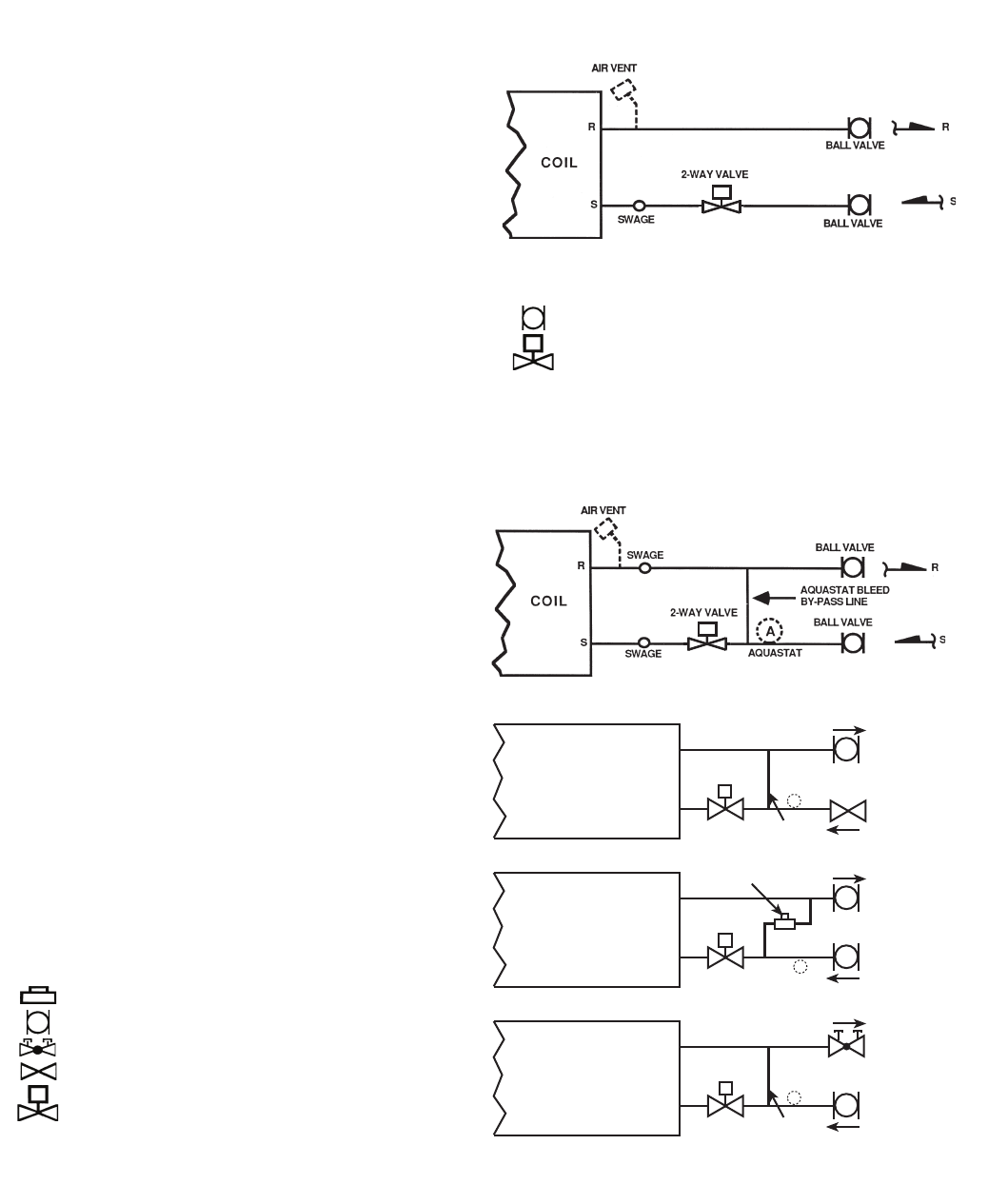
46
BALL VALVE
GATE
SHUT OFF
(1) GATE
(1) BALL
(1) 2-WAY MOTORIZED R
S
COIL
BALL VALVE
BALL VALVE
(2) BALL
(1) BALANCING
(1) 2-WAY MOTORIZED R
S
COIL
CIRCUIT SETTER
BALL VALVE
(1) BALL
(1) CIRCUIT SETTER
(1) 2-WAY MOTORIZED R
S
COIL
MOTORIZED
2-WAY VALVE
A
BYPASS
BALANCING
VALVE
A
MOTORIZED
2-WAY VALVE
BYPASS
A
MOTORIZED
2-WAY VALVE
BYPASS
M
M
M
Fig. 44 — Two-Way Motorized Control Valve Package
Fig. 45 — Two-Way Motorized Control Valve Package with Aquastat Bleed Bypass Line
The 2-way motorized valve motor drives valve open and a
spring returns valve to normally closed position (no water
flow with unit OFF).
Supply connection at coil will be swage fit for field braze
(standard) or union (option). Return connection at coil will
be factory brazed if isolation valve only. Addition of any
other component will require swage fit for field braze or
optional union connection.
Check job specifications for system pressure, pressure drop
limitations and flow rate prior to selecting valve package
components or valve package size (1/2in., 3/4 in., etc.).
2-PIPE SYSTEM (One Valve Package) or 4-PIPE SYSTEM
(Two Valve Packages) Application:
• 2 Pipe — Hydronic Heating Only
• 2 Pipe — Hydronic Cooling Only
• 2 Pipe — Hydronic Cooling with Total Electric Heat
• 4 Pipe — Hydronic Cooling and Heating
NOTE: A 1/4-in. bypass line is included in the piping pack-
age when a 2-way valve is specified with a control package
containing an automatic changeover device.
The 2-way motorized valve motor drives valve open and a
spring returns valve to normally closed position (no water
flow through coil with unit OFF).
The aquastat bleed bypass bleeds a small amount of water
from supply to return when control valve is closed (required
for system water temperature sensing by aquastat).
Aquastat (A) clips on supply line upstream from aquastat
bleed bypass (as shown at right). It senses system water
temperature to prevent cooling operation with hot water in
system piping or heating operation with chilled water in
system piping. Additional aquastat required to lock out the
optional auxiliary electric heat when hot water in system.
Supply and return connections at coil will be swage fit for
field braze (standard) or unions (option).
Check job specifications for system pressure, pressure drop
limitations and flow rate prior to selecting valve package
components or valve package size (1/2in., 3/4 in., etc.).
2-PIPE SYSTEM (One Valve Package) Application:
• 2 Pipe — Hydronic Cooling and Heating
• 2 Pipe — Hydronic Cooling and Heating with Auxiliary
Electric Heat
NOTES: Additional aquastat required as noted above.
LEGEND
Ball Valve
Motorized 2-Way Valve
LEGEND
Balancing Valve
Ball Valve
Circuit Setter
Gate Shut Off Valve
Motorized 2-Way Valve
M
MOTORIZED
MOTORIZED
a42-4174
MOTORIZEDMOTORIZED
M
a42-4175
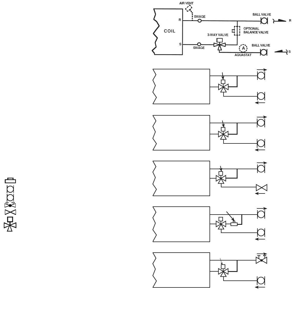
47
CIRCUIT SETTER
(1) BALL
(1) CIRCUIT SETTER
(1) 3-WAY MOTORIZED
COIL
BALL VALVE
GATE
SHUT OFF VALVE
(1) GATE
(1) BALL
(1) 3-WAY MOTORIZED R
S
COIL
BALL VALVE
BALL VALVE
(2) BALL
(1) BALANCING
(1) 3-WAY MOTORIZED R
S
COIL
MOTORIZED
3-WAY VALVE
BYPASS
BALANCING
VALVE
MOTORIZED
3-WAY VALVE
BYPASS
(1) BALL
(1) 3-WAY MOTORIZED R
S
COIL
BALANCING
VALVE BALL VALVE
BALL VALVE
(WITH MEMORY STOP)
MOTORIZED
3-WAY VALVE
BYPASS
(2) BALL (ONE WITH
MEMORY STOP)
(1) 3-WAY MOTORIZED R
S
COIL
BALL VALVE
BALL VALVE
MOTORIZED
3-WAY VALVE
BYPASS
R
S
COIL BALL VALVE
MOTORIZED
3-WAY VALVE
BYPASS
M
M
M
M
M
M
Fig. 46 — Three-Way Motorized Control Valve Package
On the 3-way motorized valve flow is normally closed to coil
and open to system return. Motor closes bypass flow to sys-
tem return while opening flow through coil. Water bypasses
coil and flows directly to system return when unit is OFF.
The aquastat (A) clips on supply line upstream from 3-way
valve (as shown above). It senses system water tempera-
ture to prevent cooling operation with hot water in system
piping or heating operation with chilled water in system pip-
ing. Aquastat(s) required for 2-pipe cooling and heating with
automatic changeover control and/or auxiliary electric heat.
A bypass balancing valve may be specified in the bypass
line to permit equal flow balancing.
Supply and return connections at coil will be swage fit for
field braze (standard) or unions (option).
Check job specifications for system pressure, pressure drop
limitations and flow rate prior to selecting valve package
components or valve package size (1/2in., 3/4 in., etc.).
2-PIPE SYSTEM (One Valve Package) or 4-PIPE SYSTEM
(Two Valve Packages) Application:
• 2 Pipe — Hydronic Heating Only
• 2 Pipe — Hydronic Cooling Only
• 2 Pipe — Hydronic Cooling with Total Electric Heat
• 2 Pipe — Hydronic Cooling and Heating
• 2 Pipe — Hydronic Cooling and Heating with Auxiliary
Electric Heat
• 4 Pipe — Hydronic Cooling and Heating
LEGEND
*When aquastat is used for automatic changeover, bypass is
required as indicated by dashed line.
NOTES:
1. Packages factory furnished and installed.
2. Valves are 5/8-in. ODS unless otherwise specified.
3. If an automatic flow control valve is added, it will be
located on supply line between shutoff valve and coil (or
motorized control valve, if supplied).
Balancing Valve
Ball Valve
Ball Valve with Memory Stop
Circuit Setter
Gate Shut Off Valve
Motorized 3-Way Valve
M
MOTORIZED
MOTORIZED
M
a42-4176
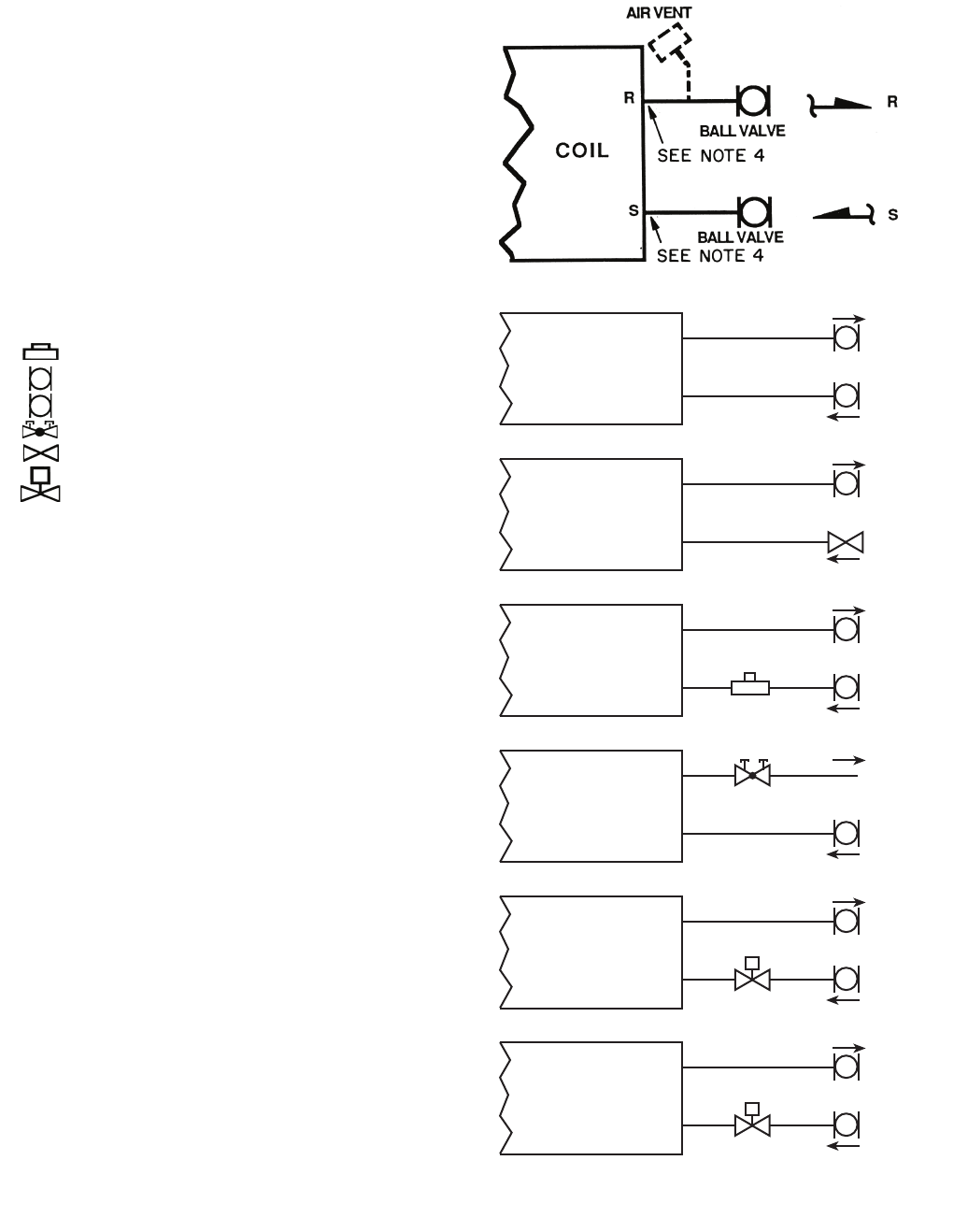
48
WITH HAND VALVES ONLY
BALL VALVE
BALL VALVE
(2) BALL
R
S
COIL
BALL VALVE
GATE SHUT
OFF VALVE
(1) BALL
(1) GATE R
S
COIL
BALL VALVE
BALL VALVE
(2) BALL
(1) BALANCING R
S
COIL
BALL VALVE
(1) BALL
(1) CIRCUIT SETTER R
S
COIL
BALL VALVE
BALL VALVE
(2) BALL
(1) 2-WAY MOTORIZED R
S
COIL
BALL VALVE (WITH
MEMORY STOP)
BALL VALVE
(2) BALL (ONE WITH
MEMORY STOP)
(1) 2-WAY MOTORIZED R
S
COIL
BALANCING
VALVE
MOTORIZED
2-WAY VALVE
M
MOTORIZED
2-WAY VALVE
CIRCUIT SETTER
M
M
Fig. 47 — Valve Package without Motorized Control
When isolation valves only are specified, they will be brazed
to the coil stub-outs.
Check job specifications for system pressure, pressure drop
limitations and flow rate prior to selecting specific compo-
nents or valve package size (1/2 in., 3/4 in., etc.).
2-PIPE SYSTEM ONLY (One Valve Package) Application:
• 2 Pipe - Hydronic Heating Only
• 2 Pipe - Hydronic Cooling Only
NOTES:
1. Continuous water flow, chilled water or hot water.
2. Not recommended for high humidity applications.
3. Not recommended with unit-mounted thermostat on
vertical units (except package R).
4. The addition of any other component(s) will
require swage fitting for field braze or optional union
connection.
LEGEND
*When aquastat is used for automatic changeover, bypass is
required as indicated by dashed line.
NOTES:
1. Packages factory furnished and installed.
2. Valves are 5/8-in. ODS unless otherwise specified.
3. If an automatic flow control valve is added, it will be
located on supply line between shutoff valve and coil (or
motorized control valve, if supplied).
Balancing Valve
Ball Valve
Ball Valve with Memory Stop
Circuit Setter
Gate Shut Off Valve
Motorized 2-Way Valve
M
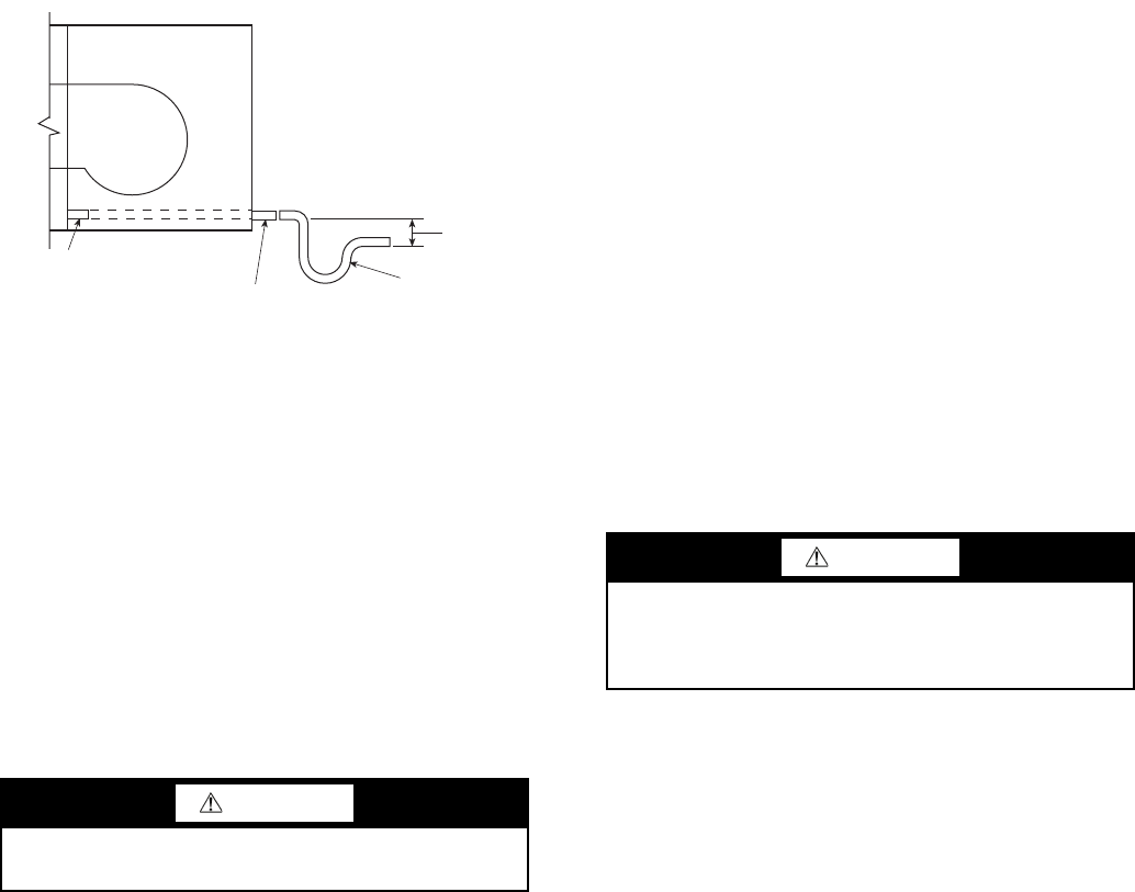
49
42C,D,V DRAIN CONNECTIONS — Install drain line in
accordance with all applicable codes. A continuous pitch of
1 in. per 10 ft of condensate drain line run is necessary for
adequate condensate drainage. Insulate the drain line to
prevent sweating. Extend the drain line straight from the drain
pan before making any turns. The installer must provide proper
support for the drain line to prevent undue stress on the
auxiliary drain pan.
Install trapped drain line in accordance with all applicable
codes (see Fig. 48). A drain trap may be required by local
codes and is recommended for odor control. The differential
height inlet to outlet must be at least 1-in. wg greater than the
total static pressure of the unit. The differential height of the
outlet to the bottom of the trap must not be less than the total
static pressure of the unit.
Provide a trap of at least 2-in. near the end of the drain line
to prevent odors from entering the rooms.
42C,D,V WATER SUPPLY/RETURN CONNECTIONS —
Install piping in accordance with all applicable codes. Position
valves over the drain pan. Be sure valves are in proper operat-
ing position and are easily accessible for adjustment. See
Fig. 44-47. Refer to Fig. 49 for copper water tube and joint
material pressure ratings.
If coil and valve package connections will be made with a
solder joint, care should be taken to ensure that the components
in the valve package are not subjected to high temperatures,
which may damage seals or other materials. Many 2-position
electric control valves are provided with a manual operating
lever. This lever should be in the OPEN position during all
soldering operations.
If coil connection is made with a union, the coil side of the
union must be prevented from turning (it must be backed up)
during tightening. See Fig. 44-47 for common valve packages.
NOTE: The project specifications for system pressure, pres-
sure drop limitations, and flow rate should be checked prior to
selection of specific components or the valve package size.
42C,D,V STEAM CONNECTIONS — On units with steam
heating coils, the maximum steam pressure applied to the unit
should never exceed 10 psig. However, when steam is used on
a 4-pipe application system with 1-row and 2-row coils the
maximum steam pressure should never exceed 5 psig (suitable
for only low pressure steam).
Do not drain the steam mains or take-off through the coils.
Drain the mains ahead of the coils through a steam trap to the
return line. Overhead returns require 1 psig of pressure at the
steam trap discharge for each 2 ft elevation to ensure continu-
ous condensate removal.
Proper steam trap selection and installation is necessary. As a
guideline in creating a steam trap locate the steam trap dis-
charge at least 12 in. below the condensate return connection.
This provides sufficient hydrostatic head pressure to overcome
trap losses and ensure complete condensate removal.
42C,D,V DIRECT EXPANSION (DX) REFRIGERANT
PIPING — Use the condensing unit manufacturer's recom-
mended line sizes and requirements. Suction line must be
insulated for correct operation. Use refrigerant-grade copper
lines only. The unit is not applied as a heat pump.
Thermostatic expansion valve (TXV) and sensing bulb are
factory-installed on units when DX coil option is chosen with
distributor and TXV.
NOTE: If a hot water coil is used in the reheat position, a field-
supplied freezestat must be installed to protect the coil.
TEST AND INSULATE — When all joints are complete,
perform hydrostatic test for leaks. Vent all coils at this time.
Check interior unit piping for signs of leakage from shipping
damage or mishandling. If leaks are found, notify a Carrier
representative before initiating any repairs. Release trapped air
from system (refer to Make Final Preparations section).
Never pressurize any equipment beyond specific test pres-
sure. Always pressure test with an inert fluid or gas, such as
clear water or dry nitrogen to avoid possible damage or injury
in the event of a leak or component failure during testing.
Following the hydrostatic test, insulate all piping to prevent
sweating.
To ensure compliance with building codes, restore the struc-
ture's original fire resistance rating by sealing all holes with
material carrying the same fire rating as the structure.
CAUTION
DO NOT OVERTIGHTEN! Overtightening will distort
(egg shape) the union seal surface and destroy the union.
CONDENSATE
PAN STUB-OUT
7/8 IN. FIELD-SUPPLIED
DRAIN EXTENSION
TRAP
2 IN. MIN
Fig. 48 — Typical Drain Line Details
(42D Unit Shown)
CAUTION
All water coils must be protected from freezing after initial
filling with water. Even if system is drained, unit coils may
still have enough water to cause damage when exposed to
temperatures below freezing.
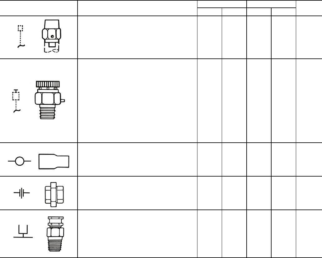
50
Table 5 — Piping Components
LEGEND
*Check all system component pressure ratings (coils, values,
pumps, etc.) with manufacturer and any applicable local or national
piping codes prior to specifying system pressure rating.
NOTES:
1. Motorized 2-way valves have a maximum close-off differential
of 25 psi.
2. Motorized 3-way valves have a maximum close-off differential
of 10 psi.
SYMBOL/SKETCH DESCRIPTION CV FACTOR RATING* STEAM
USE
1/2 in. 3/4 in. PSI F
MANUAL AIR VENT: Threaded brass needle
valve with screwdriver slot for adjustment.
Application — Body brazed into high point of
heating and cooling coils for bleeding air from
coil. Standard item on all hydronic coils (not
used on steam or DX coils). Should not be
used in lieu of main system air vents.
N/A N/A 400 100 NO
AUTOMATIC AIR VENT: Nickel plated brass
valve, fiber-disc type, with positive shut-off ball-
check and quick vent feature via knurled vent
screw.
Application — Optional replacement for man-
ual air vent. Automatically passes minute
quantities of air through the fiber discs which
expand upon contact with water, completely
sealing the valve. As air accumulates, the fiber
discs dry and shrink, repeating the cycle. Not
recommended for removing large quantities of
air encountered during initial start-up or subse-
quent draining and refilling. Should not be
used in lieu of main system air vents.
N/A N/A 125 240 NO
SWAGE: Copper tube end expanded to accept
a copper tube of the same size for factory or
field brazing.
Application — Used where possible for all tub-
ing joints for best joint integrity.
N/A N/A 300 200 YES
UNION: Combination wrought copper/cast
brass union assembly, solder by solder.
Application — Used for quick connect (and dis-
connect) of valve package components to min-
imize field labor and facilitate servicing of unit.
N/A N/A 300 200 YES
INSERTION TEST PORT: Brass body valve
for acceptance of test probe (up to 1/8 in.
diameter).
Application — Installed on one (or both) sides
of the coil to allow for temperature or pressure
sensing. Used for close tolerance water bal-
ancing and service analysis.
N/A N/A 250 250 NO
Cv — Coefficient of Velocity
DX — Direct Expansion
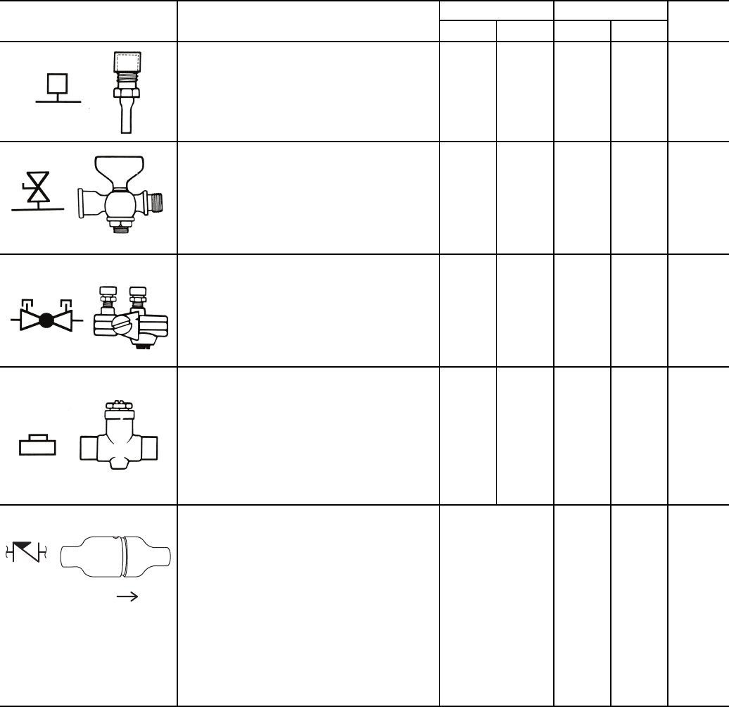
51
Table 5 — Piping Components (cont)
LEGEND
*Check all system component pressure ratings (coils, values,
pumps, etc.) with manufacturer and any applicable local or national
piping codes prior to specifying system pressure rating.
NOTES:
1. Motorized 2-way valves have a maximum close-off differential
of 25 psi.
2. Motorized 3-way valves have a maximum close-off differential
of 10 psi.
SYMBOL/SKETCH DESCRIPTION CV FACTOR RATING* STEAM
USE
1/2 in. 3/4 in. PSI F
PRESSURE TEST PORT: Brass body 1/4 in.
service access fitting with removable depres-
sor type core.
Application — Installed on both sides of the
coil to allow for pressure sensing. Attach
pressure gages to facilitate close tolerance
water balancing.
N/A N/A 400 210 NO
GAGE COCK: Brass shut-off valve with
1/4 in. FPT fitting for attachment of pressure
gages.
Application — Installed on both sides of the
coil to allow for pressure sensing. Attach
pressure gages to facilitate close tolerance
water balancing. May be used in bleed
bypass line to regulate water flow.
N/A N/A 200 250 N/A
CIRCUIT SETTER: Variable water flow bal-
ancing valve with manual adjustment knob,
pointer, percent-open scale, memory stop
and integral pressure read-out ports.
Application — Used for close tolerance water
flow balancing. Positive shut-off ball valve
feature allows usage as combination balanc-
ing and shut-off valve.
2.12 3.9 300 250 NO
BALANCE VALVE: Variable water flow man-
ual balancing valve with screwdriver slot
adjustment screw.
Application — Often used in conjunction with
test port fittings for water flow balancing. Bal-
ance by temperature differential or coil pres-
sure drop (check specifications for service
fittings required if balancing by pressure
drop). May be used in 3-way valve bypass
line to permit equal flow balancing.
3.0 8.9 150 200 NO
FIXED FLOW VALVE: Flexible orifice type
(non-adjustable).
Application — Used for water flow balancing.
Valve automatically adjusts the flow to within
10% of set point. Requires 15 psi
(35 ft) of additional pump head for proper
operation.
Valve orifice size
determines CV fac-
tor. The orifice of
these fixed flow
valves changes as
flow is regulated.
As the water pres-
sure increases,
the orifice size
decreases,
thereby automati-
cally limiting the
flow rate to the
specified gpm
(±10%).
150 160 NO
FLOW
Cv — Coefficient of Velocity
DX — Direct Expansion
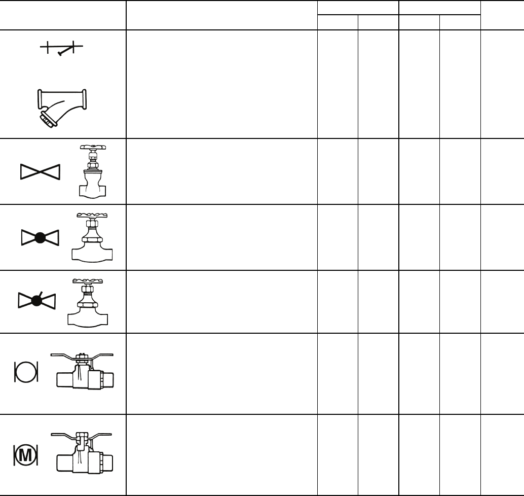
52
Table 5 — Piping Components (cont)
LEGEND
*Check all system component pressure ratings (coils, values,
pumps, etc.) with manufacturer and any applicable local or national
piping codes prior to specifying system pressure rating.
NOTES:
1. Motorized 2-way valves have a maximum close-off differential
of 25 psi.
2. Motorized 3-way valves have a maximum close-off differential
of 10 psi.
SYMBOL/SKETCH DESCRIPTION CV FACTOR RATING* STEAM
USE
1/2 in. 3/4 in. PSI F
STRAINER: Y-type body with 50 mesh stain-
less steel screen.
Application — Used for removal of small parti-
cles from system water during normal system
operation. Should not be used in lieu of main
system strainers. Strainer screen may have to
be removed during initial high pressure sys-
tem flushing during start-up. Screen should be
removed and cleaned per normal mainte-
nance schedule (provisions for strainer blow-
down not provided).
9.0
Clean
19.0
Clean 400 250 N/A
GATE VALVE: Manual shut-off valve.
Application — Used for unit isolation during
system flushing, servicing, etc. Do not use for
water balancing.
19.8 36.0 200 200 NO
GLOBE VALVE: Standard pattern, manual
shut-off and throttling valve.
Application — Used for unit isolation. Not rec-
ommended for high flow rates due to relatively
high pressure drop.
1.8 3.9 200 200 NO
COMPRESSION STOP VALVE:
Manual shut-off valve.
Application — Used for unit isolation during
system flushing, servicing, etc. Not recom-
mended for high flow rates due to relatively
high pressure drop.
2.3 5.4 150 200 NO
BALL VALVE: Manual balance and shut-off
valve.
Application — Used for unit isolation and
water flow balancing. Without memory stop
feature water balance point must be marked
by installer (if necessary). Check specifica-
tions for service fittings required when used
for water balancing.
4.0 7.5 400 200 YES
BALL VALVE WITH MEMORY STOP:
Manual balance and shut-off valve.
Application — Used for unit isolation and
water flow balancing. The adjustable memory
stop feature allows return to the balance point
after shut-off. Check specifications for
service fittings required when used for water
balancing.
4.0 7.5 400 200 N/A
Cv — Coefficient of Velocity
DX — Direct Expansion
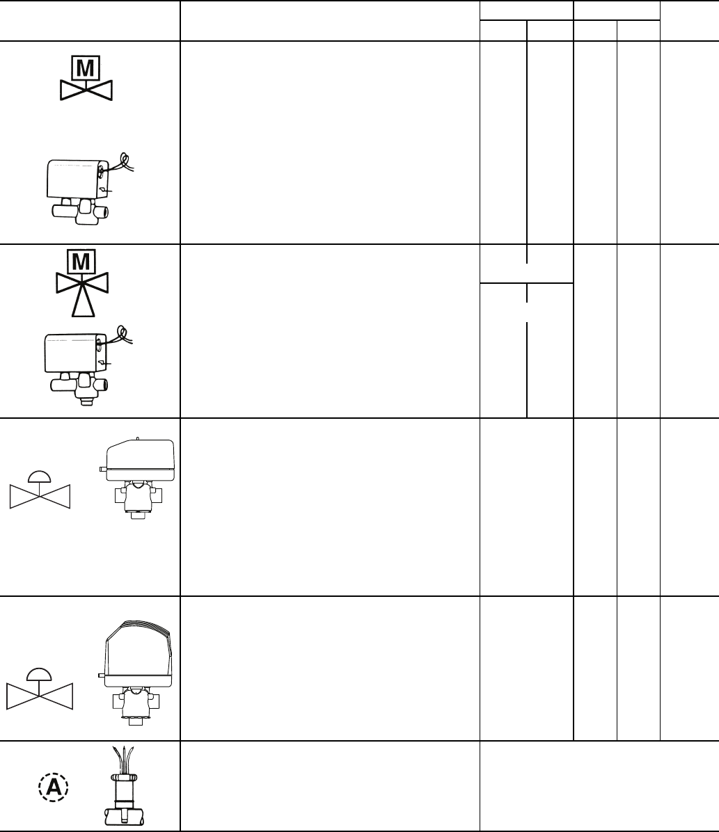
53
Table 5 — Piping Components (cont)
LEGEND
*Check all system component pressure ratings (coils, values,
pumps, etc.) with manufacturer and any applicable local or national
piping codes prior to specifying system pressure rating.
NOTES:
1. Motorized 2-way valves have a maximum close-off differential
of 25 psi.
2. Motorized 3-way valves have a maximum close-off differential
of 10 psi.
SYMBOL/SKETCH DESCRIPTION CV FACTOR RATING* STEAM
USE
1/2 in. 3/4 in. PSI F
2-WAY MOTORIZED VALVE: Electric 2-position flow
control valve (open/closed). Normally closed body
with manual override lever. Installed in supply line to
unit.
Application — All standard control and valve pack-
ages are based upon normally closed valves (valve
electrically powered open and closed by spring
return when electric power removed). Manual
override lever allows valve to be placed in the open
position for secondary (unit) flushing, constant water
flow prior to start-up, etc. Manual override is auto-
matically disengaged when valve is electrically acti-
vated. Consult factory for normally open valve
applications.
2.3 2.3 300 200
YES
15
PSI
MAX.
3-WAY MOTORIZED VALVE: Electric 2-position flow
control valve (closed to coil/open to bypass or open
to coil/closed to bypass). Normally closed with man-
ual override lever. Installed in supply line to unit.
Application — Same comments as 2-way motorized
valve except with manual override lever engaged the
valve is open to both ports and water flow will take
the path of least resistance through the valve pack-
age (not necessarily 100% through the coil).
5.0 5.0
300 200 N/A
SERVICE
2.8 2.8
BYPASS
MODULATING VALVE (Optional)
(Non-Spring Return, Floating Point Actuator):
Modulating valves are designed to control the flow in
the circuit by making incremental adjustments to the
flow path within the valve.
Application — To control fluid flow in fan coil units.
On the 42DD,SG,SJ,SH commercial fan coil units,
the factory-provided modulating valve has applica-
tion restrictions. In these models, the valve packages
are located in the air stream, downstream of the coil.
Due to the ambient temperature limitations of the
modulating valves, the valves can be used in the
units listed above only with a 2-pipe cooling system.
4.0 300 200 N/A
MODULATING VALVE (Requires ETO [Engineer-
ing to Order])
(Spring Return): Modulating valves are designed to
control the flow in the circuit by making incremental
adjustments to the flow path within the valve.
Application — Same comments as non-spring return
except when powered, the actuator moves to the
desired position, at the same time tensing the spring
return system. When power is removed for more
than two minutes the spring returns the actuator to
the normal position.
4.0 300 200 N/A
AQUASTAT: Water temperature sensing electrical
switch.
Application — Clips directly on nominal size 1/2 in. or
3/4 in. copper tubing for water temperature sensing.
Must be correctly located for proper control
operation.
Cv — Coefficient of Velocity
DX — Direct Expansion
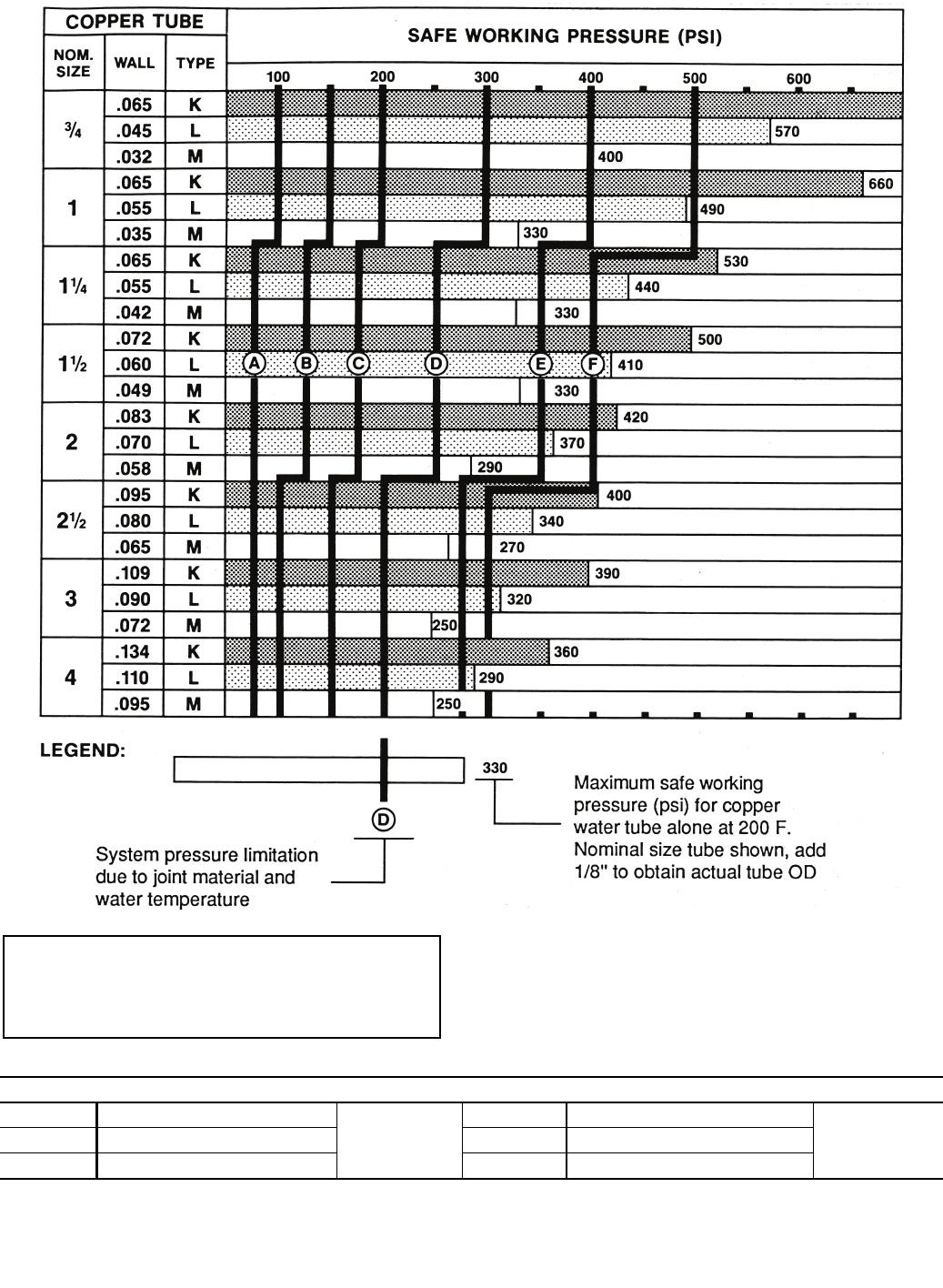
54
Fig. 49 — Copper Water Tube and Joint Material Pressure Ratings
NOTES:
1. Not recommended for high system water pressures.
2. Standard factory joint material.
JOINT MATERIALS
A50-50 Lead-Tin at 200 F
Note 1
D95-5 Tin-Antimony at 200 F
Note 2B50-50 Lead-Tin at 150 F E95-5 Tin-Antimony at 150 F
C50-50 Lead-Tin at 100 F F95-5 Tin-Antimony at 100 F
IMPORTANT: THE ABOVE CHART IS FOR
REFERENCE ONLY. Check all system component
pressure ratings (coils, valves, pumps, etc.) and any
applicable local or national piping codes prior to
specifying system pressure rating.

55
Step 3 — Make Electrical Connections — Refer
to unit nameplate for required supply voltage, fan and heater
amperage and required circuit ampacity. Refer to unit wire dia-
gram for unit and field wiring. Make sure all electrical connec-
tions are in accordance with unit wiring diagram and all appli-
cable codes.
The fan motor(s) should never be controlled by any wiring
or device other than the factory-supplied switch or thermostat/
switch combination unless prior factory authorization is
obtained. Fan motor(s) may be temporarily wired for use
during construction only with prior factory approval and only
in strict accordance with the instructions issued at that time.
Floor cabinet type units have factory-wired integral fan
switches. Connect power wires to leads in unit junction box per
unit wiring diagram. On the other units, install remote fan
switch according to job drawings. Hook up switch and power
wiring per unit wiring diagram.
Install optional, wall-mounted thermostat per instructions
shipped with thermostat. Connect as shown on unit wiring
diagram.
Units with factory-supplied and factory-installed aquastats
may be shipped with the aquastats mounted on a coil stub-out.
If this is the case, remove the aquastat before installing valve
package. When reinstalling aquastats, consult the factory-
piping diagram in the submittal for proper location. If the valve
package is field-supplied, the aquastat must be installed in a
location where it will sense the water temperature regardless of
the control valve position. A bleed bypass may be required to
guarantee proper aquastat operation. The aquastat bypass line
allows a small amount of water to flow from the supply to the
return piping when the control valve is closed.
NOTE: The aquastat must be able to sense whether the
flowing water is being chilled or heated and switches a contact
closed to provide automatic summer or winter changeover for
the system. When a two-pipe cooling/heating system with
optional auxiliary electric heat is desired, an additional
aquastat is required.
All field wiring must be in accordance with governing
codes and ordinances. Any modification of unit wiring without
factory authorization will invalidate all factory warranties and
nullify any agency listings.
Units may be equipped with line voltage controls or
24 VAC control systems. The following descriptions are for
line voltage controls only. For 24 v control operating sequence,
refer to thermostat operating instructions.
STANDARD WIRING PACKAGES
Manual Fan Control — On all vertical cabinet units, the stan-
dard fan-speed switch is furnished unit-mounted and wired.
See Fig. 50. On all vertical furred-in units and all horizontal
units, the switch is shipped separately on a decorative wall
plate for field mounting and wiring.
The standard switch has LOW, MEDIUM, HIGH and OFF
positions plus an auxiliary contact to energize thermostats,
valves, dampers, etc.
NOTE: Wiring diagrams are for 120-v power supply. If other
voltages for heaters or controls are specified, wiring may differ
from that shown.
IMPORTANT: Wiring diagrams shown depict typical
control functions. Refer to unit wiring label for specific
functions.
Fig. 50 — Manual Fan Control
NOTES:
1. Motors are thermally protected.
2. Use copper conductors only.
3. See unit nameplate for power supply. Provided disconnect
means and overload protection as required.
4. Unit-mounted thermostats are not recommended for fan control
because of poor temperature sensing. Fan control not available
on 42VC,VE lowboy units.
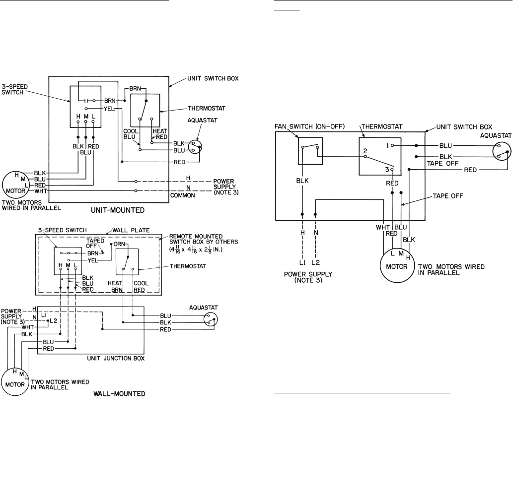
56
Thermostatic Fan Control, 2-Pipe Systems — The thermo-
stat cycles the fan on and off from any selected speed setting to
maintain selected room temperature. Controls can be wired for
heating-only, cooling-only or for heating/cooling by the addi-
tion of an automatic changeover device that senses water tem-
perature and changes the action of the thermostat as required.
See Fig. 51.
Thermostatic Fan Control, 2-Pipe System with Safety
Cycle — This control is used for high humidity situations in
which condensate problems can occur if fan is turned off while
chilled water is still running through the coil.
The wiring provides fan cycling from HIGH to LOW on the
cooling cycle and from LOW to OFF on the heating cycle. An
ON-OFF toggle switch replaces the standard 3-speed fan
switch. The toggle switch can be concealed to ensure that the
unit runs on low speed when cooling. This action greatly
reduces the chance of condensation problems that exist with
other standard fan cycling controls. See Fig. 52.
Thermostatic Electric Valve Control, 2-Pipe — A thermo-
statically controlled 2-position valve provides superior control
to fan cycling. With this control, the fan runs continuously un-
less it is manually switched to the OFF position. The fan must
be on before the valve can be opened to supply water to the
coil.
This system can be used for normal 2-pipe changeover
systems and can also be furnished for cooling-only or heating-
only applications by omitting the changeover and specifying
which application is intended. See Fig. 53 and 54 for line volt-
age control. See Fig. 55 and 56 for 24-v control.
Fig. 51 — Thermostatic Fan Control
(2-Pipe System)
NOTES:
1. Motors are thermally protected.
2. Use copper conductors only.
3. See unit nameplate for power supply. Provide disconnect
means and overload protection as required.
4. Unit-mounted thermostats are not recommended for fan control
because of poor temperature sensing. Fan control not available
on 42VC,VE lowboy units.
Fig. 52 — Thermostatic Fan Control
(2-Pipe System with Safety Cycle)
NOTES:
1. Motors are thermally protected.
2. Use copper conductors only.
3. See unit nameplate for power supply. Provide disconnect
means and overload protection as required.
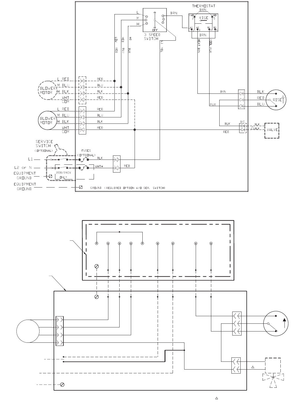
57
Fig. 53 — 42SG,SH,SJ,VA,VB,VC,VE,VF 2-Pipe Heating and Cooling with
Automatic Changeover — Unit-Mounted Thermostat (Line Voltage)
a42-4060
120-V WHT ALL OTHERS BLK
NEC CLASS 1 WIRING
UNIT MOUNTED
J BOX
EQUIPMENT
GROUND
L2 or N
L1
THERMOSTAT PART # 702893-36
MED W/RED
HI W/ORG
L1 BLK
LOW W/BRN
HEAT RED
COOL BLU
PUR
ORG
L2 OR N YEL
VALVE
WHT
BLK
REMOTE DEVICE BOX
*WHT
AQUASTAT
BLK
BLU
RED
2
1
3
2
1
BLOWER
MOTOR H BLK
COM
WHT
BLUM
REDL 4
3
2
1
PUR
BRN
BLK
ONLY 120V WHT/ALL OTHERS BLK
RED
BLU
BLK
*WHT
NEC CLASS 1 WIRING
RISE
Fig. 54 — 42C,S,V and 42D (600-1000) 2-Pipe Heating and Cooling with Automatic Changeover —
Remote/Wall-Mounted Thermostat (Line Voltage)
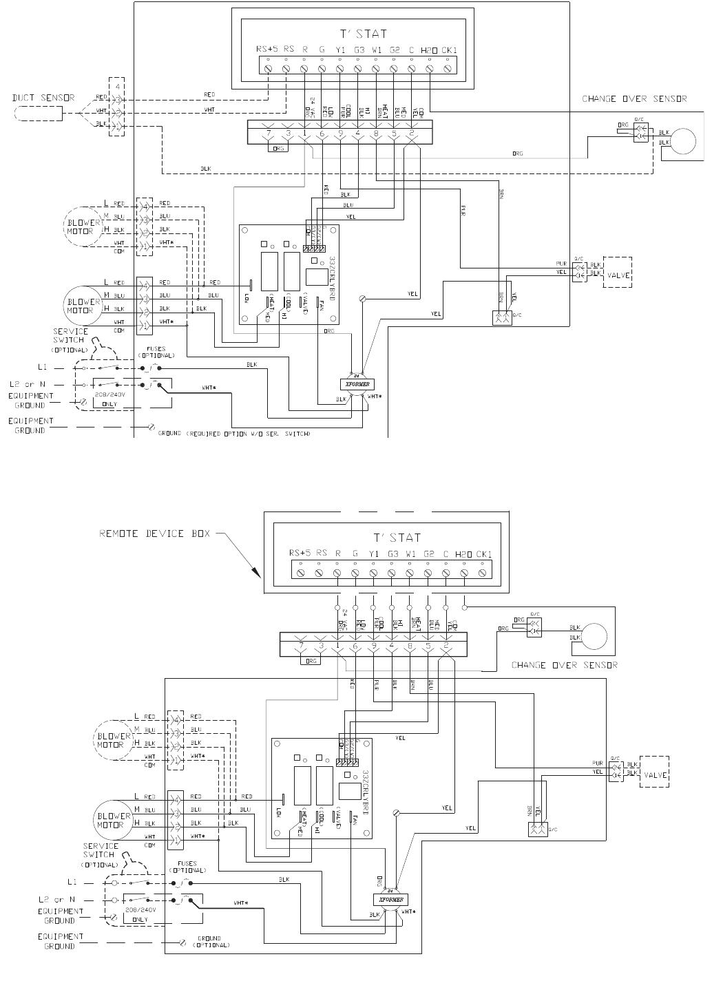
58
Fig. 55 — 42SG,SH,SJ,VA,VB,VF 2-Pipe Heating and Cooling with Automatic Changeover —
Unit-Mounted Debonair® Thermostat (24-v), Duct Sensor
a42-4059
Fig. 56 — 42C,S,V (except VG), and 42D (600-1000 cfm) 2-Pipe Heating and Cooling with
Automatic Changeover — Remote/Wall-Mounted Debonair® Thermostat (24-v)
a42-4061
NEC CLASS 2 WIRING
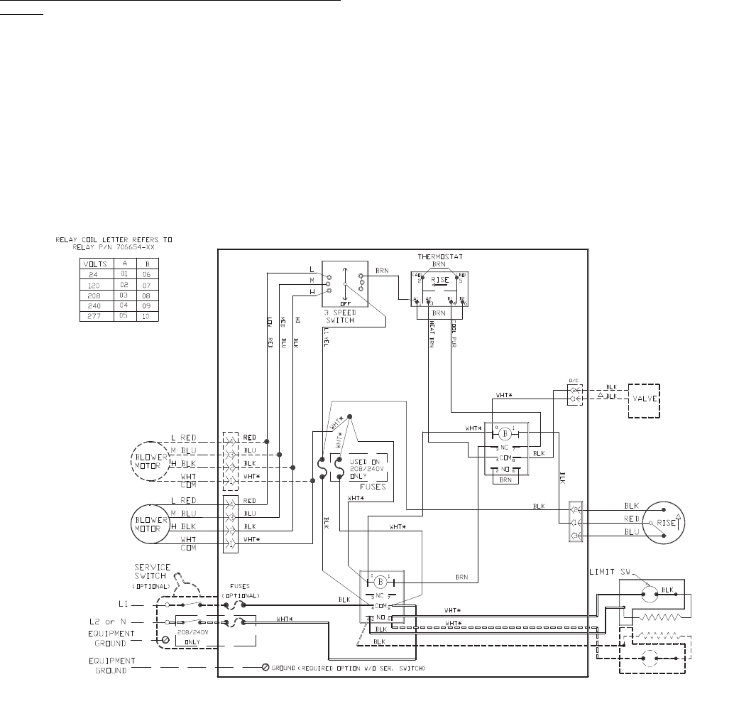
59
Thermostatic 2-Pipe Auxiliary Electric Heat with Valve
Control — This system, also called twilight or intermediate
season electric heat, goes a long way towards solving the
spring and fall control problems of 2-pipe systems.
Chilled water can be run late into the fall, turned on early in
the spring and heat will still be available to all units whenever
required.
In winter the system is switched over to hot water. Two
changeover devices are required for this. One device switches
the action of the thermostat and the other locks out the electric
heat when hot water is in the coil.
With this system, the fan runs continuously unless manually
switched to OFF position. Fan must be on before thermostat
can send signal to open chilled water valve or turn on electric
heater.
Two control methods are available:
1. Use the standard automatic changeover thermostat with a
dead band between heating and cooling.
2. Use a manual changeover thermostat. With this method
only one changeover is required.
Be sure to include a 2-way or 3-way electric valve with this
system.
NOTE: Wiring diagrams are for 120-v power supply. If other
voltages for heaters or controls are specified, wiring may differ
from that shown. See Fig. 57 and 58 for line voltage control.
See Fig. 59 and 60 for 24-v control.
Fig. 57 — 42SG,SH,SJ,VA,VB,VC,VE,VF 2-Pipe Heating and Cooling with Auxiliary Heat —
Unit-Mounted Thermostat (Line Voltage)
a42-4066
120-V WHT ALL OTHERS BLK
NEC CLASS 1 WIRING
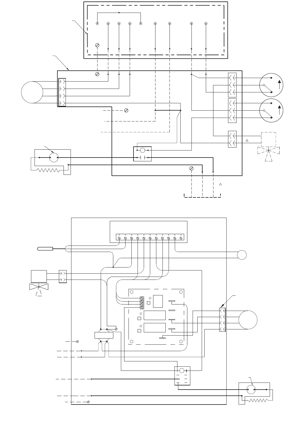
60
Fig. 58 — 42C,S,V (except VG), and 42D (600-1000 cfm) 2-Pipe Heating and Cooling with
Auxiliary Heat — Remote/Wall-Mounted Thermostat (Line Voltage) and Dual Power Source
UNIT MOUNTED
J BOX
EQUIPMENT
GROUND
L2 or N
L1
THERMOSTAT PART # 702893-36
W/RED
HI W/ORG
L1 BLK
LOW W/BRN
HEAT RED
COOL BLU
PUR
ORG
L2 OR N YEL
VALVE
REMOTE DEVICE BOX
*WHT
LIMIT SWITCH
AQUASTATS
CONTACTOR
1
L1
L2 OR N
GRN
*WHT
BLKBLKBLK
*WHT WHT
BLK
RED
PUR
BRN
BRN
RED
*WHT
BLOWER
MOTOR H BLK
COM
WHT
BLUM
REDL
QUICK CONNECT
OPTIONAL
RED
BLU
BLK
*WHT
ONLY 120V WHT/ALL OTHERS BLK
RISE
BLK
BLU
RED
RISE
BLK
BLU
RED
Fig. 59 — 42SG,SH,SJ,VA,VB,VC,VE,VF 2-Pipe Heating and Cooling with Auxiliary Heat —
Unit-Mounted Debonair® Thermostat (24-v), Duct Sensor and Dual Power Source
QUICK CONNECT
33
G
G2/(W)
G3/(Y)
COM
FAN
(VALVE)
(COOL)
HI
(HEAT) MED
LOW
TRANSFORMER
24
ORG YEL
WHT/REDBLK
VALVE
BLK Q/C
BLK
YEL
YEL
YEL
BLU
BLK
PUR
RED
ORG
BLK
BLOWER
MOTOR
COM
WHT
BLK H
BLU M
RED L
4
3
2
1
*WHT
2
1
BLK
LIMIT SWITCH
BLK BLK
BRN
BRN
WHT
GROUND
EQUIPMENT
L1
N
RED
BLU
BLK
BLK
YEL
G
THERMOSTAT #33CSSN2-FC
RG3Y1 W1 CG2 H2O CK1RSRS+5
DUCT SENSOR 33CSSEN-DS RED
BLK
WHT
GROUND
EQUIPMENT
L2 or N
L1
*WHT
BLK
SENSOR
CHANGE OVER
BLK
BLK
YEL
RED
BLU
BLK
*WHT
CONTACTOR
ELEC. HEATER
2NO 6
COM
4
3NC
0
06
8
7
1
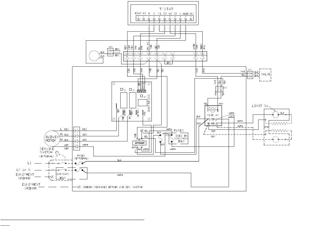
61
Thermostat 2-Pipe Total Electric Heat with Valve Con-
trol — With this system, the complete heating requirement for
the space is provided by the electric heater; the water system is
never changed over for heating. It is therefore possible, just as
with 4-pipe systems, to have heating or cooling at any time of
the year.
The fan runs continuously unless it is manually switched to
OFF position. Fan must be on before thermostat can send
signal to open chilled water valve or turn on electric heater.
Normally, an automatic changeover thermostat with a dead
band between heating and cooling is used, but a manual
changeover thermostat is also suitable. A 2-way or 3-way valve
must also be used so that the chilled water is off whenever the
heater is on. No changeover device to sense water temperature
is necessary.
NOTE: Wiring diagrams are for 120-v power supply. If other
voltages for heaters or controls are specified, wiring may differ
from that shown. See Fig. 61 and 62 for line voltage control.
See Fig. 63 and 64 for 24-v control.
Fig. 60 — 42C,S,V (except VG), and 42D (600-1000 cfm) 2-Pipe Heating and Cooling with
Auxiliary Heat — Remote/Wall-Mounted Debonair® Thermostat (24-v)
a42-4067
NEC CLASS 2 WIRING
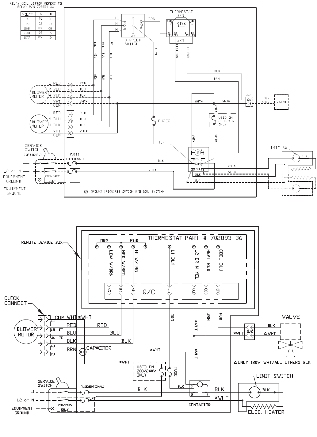
62
Fig. 61 — 42SG,SH,SJ,VA,VB,VC,VE,VF 2-Pipe Cooling with Total Electric Heat —
Unit-Mounted Thermostat (Line Voltage)
a42-4073
120-V WHT ALL
OTHERS BLK
NEC CLASS 1 WIRING
Fig. 62 — 42C,S,V (except VG), and 42D (600-1000 cfm) 2-Pipe Cooling with Total Electric Heat —
Remote/Wall-Mounted Thermostat (Line Voltage)
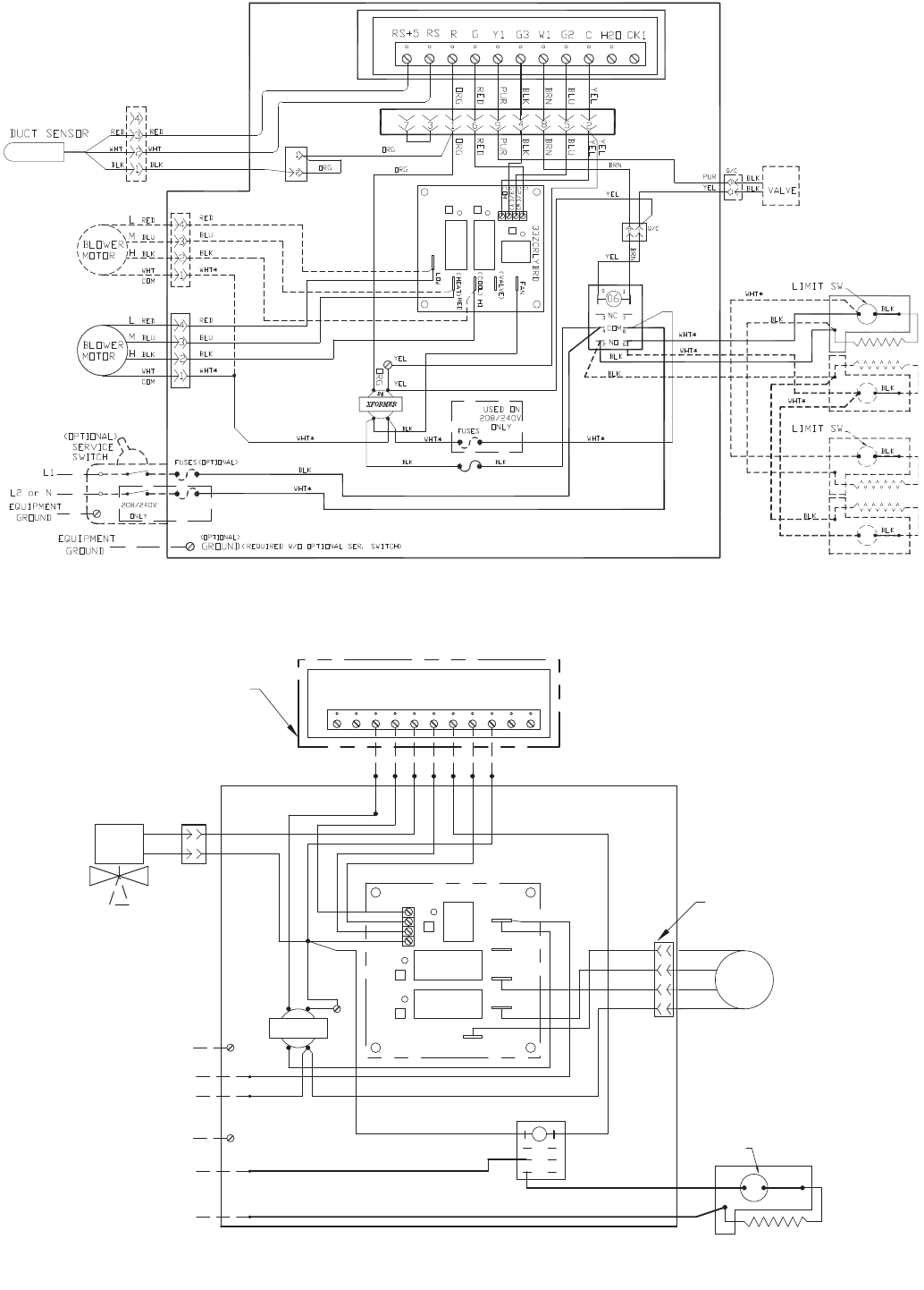
63
Fig. 63 — 42SG,SH,SJ,VA,VB,VC,VE,VF 2-Pipe Cooling with Total Electric Heat —
Unit-Mounted Debonair® Thermostat (24-v) and Duct Sensor
a42-4072
NOTE: Units may have 2 or 4
elements. Elements wired in
parallel.
Fig. 64 — 42C,S,V (except VG), and 42D (600-1000 cfm) 2-Pipe Cooling with Total Electric Heat —
Remote/Wall-Mounted Debonair® Thermostat (24-v) and Dual Power Source
G
THERMOSTAT #33CSSN2-FC
RG3Y1 W1 CG2 H2O CK1RSRS+5
REMOTE DEVICE BOX
QUICK CONNECT
NEC CLASS 2 WIRING
(HEAT)
(COOL)
(VALVE)
FAN
GROUND
EQUIPMENT
N
L1
L2 or N
EQUIPMENT
GROUND
L1
BLK
WHT
24
TRANSFORMER
*WHT
BLK
BLK
ORG
*WHT
WHT/RED
YEL
YEL
LOW
2
Q/C
BLK 1
BLK
YEL
YEL
33ZCRLYBRD
G3/(Y)
G2/(W)
COM
G
RED
ORG
PUR
BLK
BRN
BLU
YEL
*WHT WHT COM
BLK
BRN
MED
LIMIT SWITCH
BLK
1
HI
BLK
RED
BLK
BLU
LRED
BLU
BLK
3
2
4
H
M
MOTOR
BLOWER
COOL
VALVE
ELEC. HEATER
8
4
NO
26
06
NC
COM
3
0
7
1
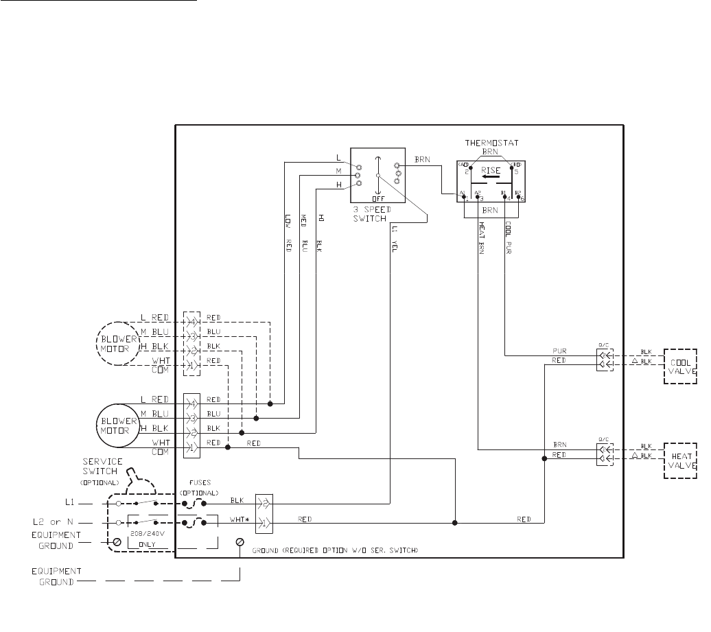
64
Thermostatic Valve Control, 4-Pipe — The 4-pipe system
provides the ultimate in economy and room temperature con-
trol. Both hot water and chilled water are available at any time.
Normally an automatic changeover thermostat is used, but a
manual changeover thermostat is also suitable. Two 2-way
valves, two 3-way valves, or one 2-way plus one 3-way valve
must be selected. An automatic changeover device to sense
water temperature is not required.
With this system, the fan runs continuously unless it is
manually switched to OFF position. Fan must be on before
thermostat can send signal to open the chilled water or hot
water valve.
NOTE: Wiring diagrams are for 120-v power supply. If other
voltages for heaters or controls are specified, wiring may differ
from that shown. See Fig. 65 and 66 for line voltage control.
See Fig. 67 and 68 for 24-v control.
Fig. 65 — 42SG,SH,SJ,VA,VB,VC,VE,VF 4-Pipe Heating and Cooling —
Unit-Mounted Thermostat (Line Voltage)
a42-4079
120-V WHT ALL OTHERS BLK
NEC CLASS 1 WIRING
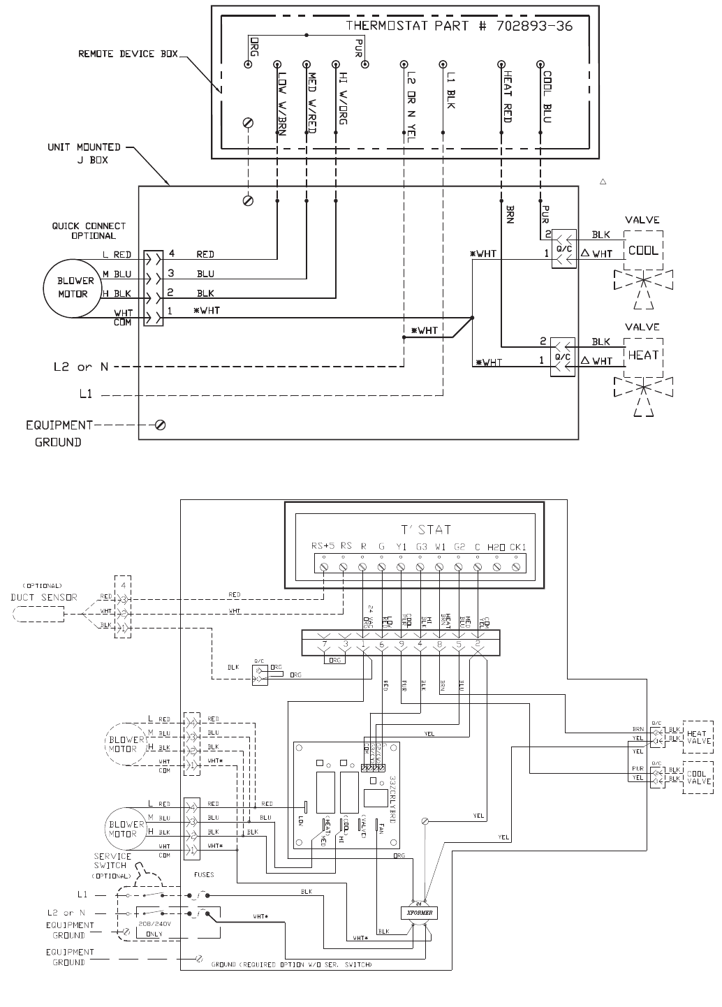
65
Fig. 66 — 42C,S,V (except VG), and 42D (600-1000 cfm) 4-Pipe Heating and Cooling —
Remote/Wall-Mounted Thermostat (Line Voltage)
ONLY 120V WHT/ALL
OTHERS BLK
Fig. 67 — 42SG,SH,SJ,VA,VB,VC,VE,VF 4-Pipe Heating and Cooling —
Unit-Mounted Debonair® Thermostat (24-v) and Duct Sensor
a42-4078
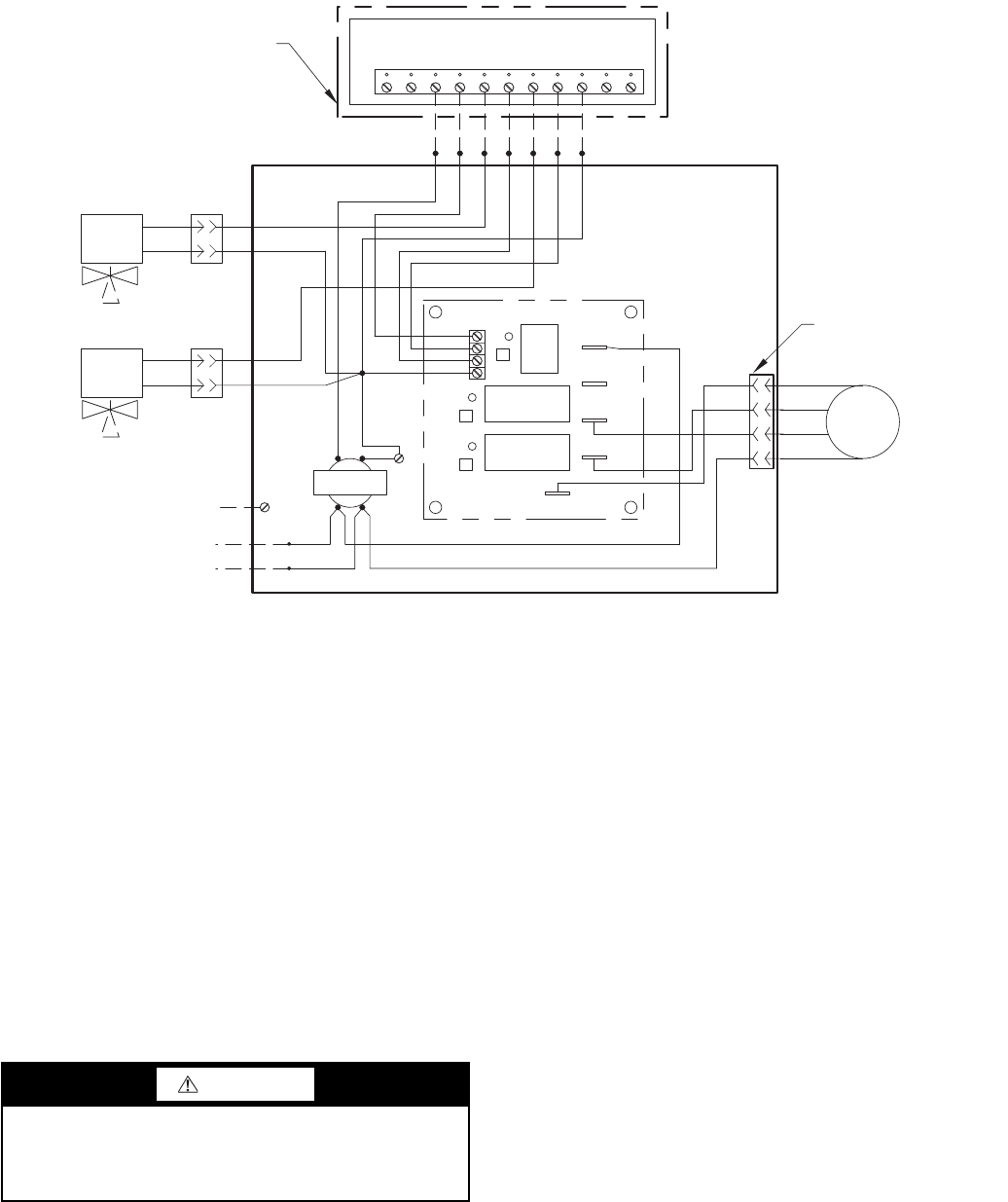
66
Step 4 — Make Duct Connections — Install all
ductwork to and from unit in accordance with all applicable
codes. Duct construction must allow unit to operate within duct
external static pressure limits as shown on job submittals. Units
designed to operate with ductwork may be damaged if operated
without intended ductwork attached.
Units provided with outside air should have some method
of low-temperature protection to prevent freeze-up.
Insulate ductwork as required. Use flexible connections to
minimize duct-to-unit alignment problems and noise transmis-
sion where specified.
Set unit markings for minimum clearance to combustible
materials and first 3 ft of ductwork. Install ductwork, accessory
grilles and plenums so that they do not restrict access to filter.
Cut openings for supply-air and return-air grilles, thermostats
and switch plates where specified on job drawings. Be careful
not to cut wires, piping or structural supports. Use a steel ther-
mostat shield ring to protect drywall from thermostat wiring
where applicable.
Step 5 — Frame and Finish Unit — Models 42SG,
SH and SJ have factory enclosures and may be finished with
normally accepted wall covering. However, drywall secured
with adhesive bonding alone is not recommended.
Use low-profile sheet metal panhead screws to secure
wallboard to unit frame.
Do not apply sheet metal screw or nails where they can pen-
etrate coil, riser pipes, or electrical junction box and raceways.
Do not secure wallboard to drain pan edges or to control
box enclosure. Condensate leaks or electrical shorts may result.
An alternate method of enclosing the unit is to frame one or
more sides with studding and apply the wall board to this fram-
ing. This method requires specific unit features and return ac-
cess panels when used on the return-air side of a unit. Units not
properly equipped will exhibit poor cooling and/or heating per-
formance and could experience excessive or premature compo-
nent failures.
Prevent sheetrock dust or other debris from settling on coil
fins, motor-blower assembly or other unit interior surfaces.
Return access and exposed cabinet units may be furnished
with a baked enamel finish. Small scratches in this finish may
be repaired with touch-up paint available from the factory.
Some colors of touch-up paint are available in aerosol contain-
ers and all touch-up paint is available in pint, quart, and gallon
cans.
To repaint the factory-baked enamel, the finish should be
prepared by light sanding with no. 280 grit sand paper or
no. 000 or no. 0000 fine steel wool. The surface may also be
wiped with a liquid surface etch cleaning product such as “No
Sand” or “Pasceo.” These items should be available at most
paint product stores. It should be noted that the more conscien-
tiously this preparation is done, the more effective it will be.
After this preparation is accomplished, the factory finish
should provide excellent adhesion for a variety of air-dried top
coats. Enamel will give a more durable, higher gloss finish,
while latex will not adhere as well and will give a dull, softer
finish. Top coats involving an exothermic chemical process be-
tween two components, such as epoxies and urethanes, should
be avoided.
Factory aerosol touch-up paint may require a number of
light “dust coats” to isolate the factory-baked enamel finish
from the quick drying touch-up paint.
CAUTION
Prevent dust and debris from settling in unit. If wall finish
or color is to be spray applied, cover all openings to pre-
vent spray from entering unit. Failure to do so could result
in the reduction of unit efficiency.
Fig. 68 — 42C,S,V (except VG), and 42D (600-1000 cfm) 4-Pipe Heating and Cooling —
Remote/Wall-Mounted Debonair® Thermostat (24-v)
G
THERMOSTAT #33CSSN2-FC
RG3Y1 W1 CG2 H2O CK1RSRS+5
QUICK CONNECT
REMOTE DEVICE BOX
NEC CLASS 2 WIRING
33ZCRLYBRD
G
G2/(W)
G3/(Y)
COM
FAN
(VALVE)
(COOL)
HI
(HEAT) MED
LOW
TRANSFORMER
24
YEL
BLK
VALVE
BLK Q/C
BLK
YEL
YEL
YEL
BLU
BLK
PUR
RED
ORG
BLK
BLOWER
MOTOR
COM
WHT
BLK H
BLU M
RED L
COOL
4
3
2
1
GROUND
EQUIPMENT
L1
L2 or N
*WHT
2
1
BLK
*WHT
BRN
BLK 1
HEAT
VALVE
BLK
Q/C
2
YEL
BRN
PUR
RED
BLU
BLK
YEL

67
Step 6 — Cut out Openings for Grilles and
Thermostats — On all units with optional supply-air or
return-air grilles, dampers, thermostats, and switch plates, cut
out openings where specified on the job plans. Be careful not to
cut wires, piping or structural supports.
For remote-mounted thermostats use a steel thermostat
shield ring to protect drywall from thermostat wiring where
applicable.
Prevent dirt, dust, and debris from settling in unit. If wall
finish or color is to be spray applied, cover all openings to
prevent overspray entering unit.
Step 7 — Make Final Preparations
1. Turn off power to the unit (open unit electrical disconnect).
2. Install thermostats and perform any other final wiring as
applicable.
3. Clean dirt, dust, and other construction debris from unit
interior. Be sure to check fan wheel and housing.
4. Rotate fan wheel by hand to be sure it is free and does not
rub housing. Check that wing nuts securing fan assembly
to fan deck are tight.
5. Ensure all panels and filters are installed before checking
fan operation. Turn on power to the unit.
6. Install filter in frame at front of coil. If field-supplied
filters are used, be sure size is as specified in Tables 1-4.
7. Check the fan and motor operation. The fan switch is
located in a switch box behind spring-loaded access door
on unit cabinet or is wall-mounted. Speeds are marked on
switch plate as follows:
OFF
H - High Speed
M - Medium Speed
L - Low Speed
Rotate knob clockwise to desired speed. To turn off,
rotate knob counterclockwise to OFF.
8. Be sure drain line is properly and securely positioned and
that the line is clear. Pour water into drain to check
operation.
9. Vent all air from unit coil and related piping. If air vent is
manual, release air from system by turning air vent
screw 11/2 turns counterclockwise with screwdriver.
When steady steam of water begins to escape, close
valve. If air vent is automatic, trapped air will be vented
automatically. Vent release air slowly, usually dripping
water into drain pan in the process.
Make sure all service valves are open and that the motor-
ized control valves, if supplied, are set for automatic
operation.
10. Check all control valves in the system for proper opera-
tion in accordance with valve manufacturer's instructions.
11. For units with factory-installed balancing valves, adjust
as follows:
a. Butterfly Valves — Turn valve gate by inserting
screwdriver into slot in valve top and rotating up
to 90 degrees. Valve is fully open when slot is par-
allel with valve body. When slot is perpendicular
to body, flow through valve is at minimum. Valve
does not seal against flow.
a. Ball Valves with Lever Handles — Valve gate
action is similar to butterfly valves above except
that when handle is perpendicular to valve body,
there is no flow through valve. Ball valves may be
used as shutoff valves.
START-UP
Start-up procedures vary depending on time of year (sum-
mer or winter) and building characteristics (new building/old
building, occupied/unoccupied, etc.)
Start-up in the cooling mode requires that proper care be
given to avoid condensation problems. Condensation forms on
surfaces that are colder than the dew point of the surrounding
air. If a unit is started and is piped with low-temperature chilled
water in a hot, humid atmosphere, condensation will form on
many parts of the unit. In order to avoid excessive condensa-
tion, higher temperature water should initially be used (approx-
imately 65 to 70 F) and set the fan coil control at low or medi-
um fan speed. Be sure the fan current does not exceed motor
nameplate values. Also, the building should be as completely
closed as possible and outside air supply fans, and bathroom
and kitchen exhaust fans should be off.
As the building temperature drops, the chilled water temper-
ature can be gradually reduced until it reaches 50 F. At this
point the outside air fans can be turned on. When the chilled
water temperature is reduced to its design point, the exhaust
fans can be turned on.
SERVICE
Excessive Condensation on Unit — Running chilled
water through a fan coil unit with the unit fan off can cause
excessive condensation. If fan cycling is used, a water flow
control valve should be installed to shutoff the water when the
fan stops.
Other methods of control, which avoids condensation prob-
lems, are as follows:
1. Continuous fan operation with motorized chilled water
valve controlled by a thermostat.
2. Continuous fan operation with thermostat control to
switch fan from high to low speed (instead of off).
To Clean Coil
1. Be sure electrical service switch is open, locked, and
tagged while working on unit.
2. Remove return-air grille access panel and brush between
coil fins with stiff wire brush. Follow-up by cleaning with
vacuum cleaner. If coil is cleaned with air hose and
nozzle, take care not to drive dirt and dust into other
components.
3. Install clean filter. Refer to Clean or Replace Air Filters
section.
Coil Air Vent (Manual or Automatic) — Turn vent
cap clockwise (closed) while filling system; turn counterclock-
wise (open) to vent air. Tighten clockwise after venting. Turn
automatic vent cap slightly counterclockwise until water leaks
at about 10 drops per minute. Leak will stop within one-half
minute.
Check Drain — Lock open and tag unit electrical service
switch.
Check drain pan, drain line and trap at start of each cooling
season. A standard type pipe cleaner for 3/4-in. ID pipe can be
used to ensure that pipe is clear of obstruction so that conden-
sate is carried away. Check the drain line at filter cleaning time
during the cooling season. Be sure that debris has not fallen
into unit through supply-air grille.
Fan Motor Bearings — Lock open and tag unit electri-
cal service switch.
IMPORTANT: Do not start up or operate unit without
filter. Be sure filter and unit interior are clean.
68
Standard motors are permanently sealed and lubricated. No
lubrication is required unless special motors have been
supplied or unusual operating conditions exist.
Clean Fan Wheel — Lock open and tag unit electrical
service switch.
For access to fan assembly, remove front or bottom panel.
Fan assembly may be removed from its tracks if unit has a long
conduit lead. Use a stiff brush or vacuum to remove dirt and
debris from scroll. Wipe all fan surfaces with a damp cloth.
Clean Electric Heater — Lock open and tag unit elec-
trical service switch.
1. Remove dust, dirt, or foreign material before start-up. Do
not block normal airflow to and from units; blockage may
damage electric heaters.
2. Clean heater elements with soft brush or vacuum cleaner
as necessary.
3. To replace blown fusible links (nichrome heaters only):
a. Remove fan deck (horizontal units only) for
access to heater.
b. Remove nut securing link at each end; install new
link; reinstall nuts.
c. Reinstall fan deck (if removed).
Electric resistance heaters typically require no normal peri-
odic maintenance when unit air filters are changed properly.
The operation and service life may be affected by other condi-
tions and equipment in the system. The two most important op-
erating conditions for an electric heater are proper airflow and
proper supply voltage. High supply voltage and/or poorly dis-
tributed or insufficient airflow over the element will result in
element overheating. This condition may result in the heater
cycling on the high-limit thermal cutout. The high-limit ther-
mal cutout device is a safety device only and is not intended for
continuous operation. With proper unit application and opera-
tion, the high-limit thermal cutout will not operate. This device
only operates when a problem exists, and ANY condition that
causes high-limit cutout MUST be corrected immediately.
High supply voltage also causes excessive amperage draw and
may trip the circuit breaker or blow the fuses on the incoming
power supply.
After proper airflow and supply power are assured, regular
filter maintenance is important to provide clean air over the
heater. Dirt that is allowed to deposit on the heating element
will cause hot spots and eventual element burn through. These
hot spots will normally not be enough to trip the high-limit
thermal cutout device and may not be evident until actual heat-
er element failure.
Clean or Replace Air Filters — Lock open and tag
unit electrical service switch.
At the start of each cooling season and after each month of
operation (more or less depending on operating conditions) re-
place throwaway filter or clean permanent filter.
THROWAWAY FILTER — Replace filter with a good qual-
ity filter of the size shown in Tables 1-4. Do not attempt to
clean and reuse disposable filters.
PERMANENT FILTER (FIBERGLASS TYPE)
1. Tap on solid surface to dislodge heavy particles.
2. Wash in hot water. If needed, use mild solution of com-
mercial solvent such as sal soda or trisodium phosphate.
3. Set filter on end so that water drains out through slots in
frame. Allow filter to dry thoroughly.
4. Recharge filter with Film-Cor or similar recharging oil.
Three ounces is sufficient for medium size filter. Oil may
be applied by insect spray gun. For easier spraying, the oil
can be warmed.
If the filter is dipped in the recharging oil, remove it im-
mediately and allow draining through slots in frame.
5. Replace filter in unit.
If another type of filter is used, follow the filter manufacturer's
instructions.
Warranty — All equipment and components sold through
the Parts Department are warranted under the same conditions
as the standard manufacturer's warranty with the exception that
the warranty period is thirty (30) days unless the component is
furnished as a warranty replacement. Parts furnished as war-
ranty replacements are warranted for the remaining term of the
original unit warranty or not less than thirty (30) days.

69

Manufacturer reserves the right to discontinue, or change at any time, specifications or designs without notice and without incurring obligations.
Catalog No. 04-53420004-01 Printed in U.S.A. Form 42-3SI Pg 70 12-09 Replaces: 42-2SI
Copyright 2009 Carrier Corporation

CL-1
START-UP CHECKLIST FOR 42C,D,S,V SERIES FAN COIL AIR CONDITIONERS
I. Project Information
Job Name _______________________________________________________________________
Address ________________________________________________________________________
City ______________________________________________State __________ Zip __________
Installing Contractor _______________________________________________________________
Sales Office _____________________________________________________________________
Start-up Performed By _____________________________________________________________
INSPECTION, INSTALLATION, AND START-UP CHECKLIST
ITEM COMPLETE ITEM COMPLETE
Receiving & Inspection Electrical Connections
1. Unit received undamaged 33. Refer to unit wiring diagram
2. Unit received complete as ordered 34. Connection incoming power service(s)
3. “Furnish only” parts accounted for 35. Install and connection “furnish only” parts
4. Unit arrangement/hand correct 36. All field wiring in code compliance
5. Unit structural support complete and correct Unit Start-Up
Handling & Installation 37. General visual unit and system inspection
6. Mounting grommets/isolators used 38. Check for proper fan rotation
7. Unit mounted level and square 39. Record electrical supply voltage
8. Proper access provided for unit and accessories 40. Record ambient temperatures
9. Proper electrical service provided 41. Check all wiring for secure connections
10. Proper overcurrent protection provided 42. Close all unit isolation valves
11. Proper service switch/disconnect provided 43. Flush water systems
12. Proper chilled water line size to unit 44. Fill systems with water/refrigerant
13. Proper hot water line size to unit 45. Vent water systems as required
14. Proper refrigerant line sizes to unit 46. All ductwork and grilles in place
15. Proper steam line sizes to unit 47. All unit panels and filters in place
16. Proper steam condensate trap on return line 48. Start fans, pumps, chillers, etc.
17. Proper steam supply pressure to unit (10 psi max) 49. Check for overload condition of all units
18. All service to unit in code compliance 50. Check all ductwork and units for air leaks
19. All shipping screws and braces removed 51. Balance air systems as required
20. Unit protected from direct & foreign matter 52. Record all final settings for future use
Cooling/Heating Connections 53. Check piping and ductwork for vibration
21. Protect valve package components from heat 54. Check all dampers for proper operation
22. Mount valve packages 55. Verify proper cooling operation
23. Connect field piping to unit 56. Verify proper heating operation
24. Pressure test all piping for leaks 57. Reinstall all covers and access panels
25. Install drain line and traps as required
26. Insulate all piping as required
27. Install drip lip under piping as required
Ductwork Connections
28. Install ductwork, fittings, and grilles as required
29. Flexible duct connections at unit
30. Proper supply and return grille type and size used
31. Control outside air for freeze protection
32. Insulate all ductwork as required
Manufacturer reserves the right to discontinue, or change at any time, specifications or designs without notice and without incurring obligations.
Catalog No. 04-53420004-01 Printed in U.S.A. Form 42-3SI CL-2 12-09 Replaces: 42-2SI
Copyright 2009 Carrier Corporation
-
- - - - - - - - - - - - - - - - - - - - - - - - - - - - - - - - - - - - - - - - - - - - - - - - - - - - - - - - - - - - - - - - - - - - - - - - - - - - - - - - - - - - - - - - - - - - - - - - - - - - - - - - - - - - - - - - - - - - - - - - - - - - - - - - - - - - - - - - - - - - - - - - - - - - - - - - - - - - - - - - - - - - - - - - - - - - -- - - - - - - - - - - - - - - - - - - -
CUT ALONG DOTTED LINE CUT ALONG DOTTED LINE
42 Series Fan Coil Air Conditioner Maintenance Data Log
NOTE: Indicate repairs made, refrigerant added or removed (include amounts), field controls and valve packages added.
__________________________________________________________________________________________________________________________________________________________________________
__________________________________________________________________________________________________________________________________________________________________________
__________________________________________________________________________________________________________________________________________________________________________
__________________________________________________________________________________________________________________________________________________________________
MODEL
NUMBER SERIAL NUMBER
QTY FAN AND MOTOR
FILTER
TYPE
COOLING HEATING
RH LH CFM ESP WATTS
EAT
db/wb
°F
EWT
°F GPM PD
H2O
TOTAL
BTUH
SENSIBLE
BTUH
EAT
db/wb
°F
EWT
°F GPM PD
H2O
STEAM
PSI BTUH kW VOLTAGE
