Carrier 48Tc 16 Users Manual 14SI
48TC**16 48tc-14si
48TC**16 to the manual 2b099cf9-ce13-43b1-9e3a-dcbb1f6e801e
2015-01-24
: Carrier Carrier-48Tc-16-Users-Manual-310430 carrier-48tc-16-users-manual-310430 carrier pdf
Open the PDF directly: View PDF ![]() .
.
Page Count: 48

48TC**16
Single Package Rooftop
Gas Heating/Electric Cooling Unit
with Puronr(R---410A) Refrigerant
Size 16
Installation Instructions
NOTE: Read the entire instruction manual before starting
the installation
TABLE OF CONTENTS
SAFETY CONSIDERATIONS 2....................
INSTALLATION 4...............................
Jobsite Survey 4................................
Step 1 -- Plan for Unit Location 4..................
Roof Mount 5...............................
Step 2 -- Plan for Sequence of Unit Installation 5......
Curb--Mount Installation 5.....................
Pad--Mount Installation 5......................
Frame--Mount Installation 5....................
Step 3 -- Inspect Unit 5...........................
Step 4 -- Provide Unit Support 5...................
Roof Curb Mount 5..........................
Slab Mount (Horizontal Units Only) 5...........
Alternate Unit Support
(In Lieu of Curb or Slab Mount) 5..............
Step 5 -- Field Fabricate Ductwork 7................
Step 6 -- Rig and Place Unit 7.....................
Positioning on Curb 8........................
Step 7 -- Convert to Horizontal and Connect Ductwork 8...
Step 8 -- Install Outside Air Hood 9................
Economizer Hood Removal and Setup —
Factory Option 9............................
Two Position Damper Hood Removal and Setup —
Factory Option 9............................
Economizer Hood and Two--Position Hood 10.....
Step 9 -- Install Flue Hood 10.....................
Step 10 -- Install Gas Piping 11....................
Factory--Option Thru--Base Connections
(Gas Connections) 11.........................
Step 11 -- Install External Condensate Trap and Line 13..
Step 12 -- Make Electrical Connections 14...........
Field Power Supply 14........................
All Units 15................................
Units without Factory--Installed Disconnect 15....
Units with Factory--Installed Disconnect 15.......
Convenience Outlets 16.......................
Factory--Option Thru--Base Connections
(Electrical Connections) 18....................
Units without Thru--Base Connections 18.........
Field Control Wiring 18.......................
Thermostat 18...............................
Unit without Thru--Base Connection Kit 19.......
Heat Anticipator Settings 19...................
Humidi--MiZerRControl Connections 20..........
Humidi--MiZer -- Space RH Controller 20........
PremierLinkt(Factory Option) 21.................
Supply Air Temperature (SAT) Sensor 25.........
Outdoor Air Temperature (OAT) Sensor 25.......
EconoMi$er2 25.............................
Field Connections 25..........................
Space Sensors 27............................
Connect Thermostat 27.......................
Configure the Unit for Thermostat Mode 27......
Economizer Controls 28........................
Indoor Air Quality (CO2sensor) 28.............
Outdoor Air Quality Sensor 28.................
Space Relative Humidity Sensor or
Humidistat Connections 29....................
Smoke Detector/Fire Shutdown (FSD) 30.........
Filter Status Switch 30........................
Supply Fan Status Switch 30...................
Remote Occupied Switch 30...................
Power Exhaust (output) 30.....................
CCN Communication Bus 31..................
RTU Open Control System 32.....................
Supply Air Temperature (SAT) Sensor 35.........
Outdoor Air Temperature (OAT) Sensor 35.......
EconoMi$er2 35.............................
Field Connections 35..........................
Space Temperature (SPT) Sensors 36............
Indoor Air Quality (CO2)Sensor 36.............

2
Outdoor Air Quality Sensor 37.................
Space Relative Humidity Senor or Humidistat 37..
Smoke Detector/Fire Shutdown (FSD) 38.........
Connecting Discrete Inputs 38..................
Communication Wiring -- Protocols 39............
General 39.................................
Local Access 40.............................
RTU Open Troubleshooting 40.................
Outdoor Air Enthalpy Control 41.................
Differential Enthalpy Control 41................
Return Air Enthalpy Sensor 41.................
Smoke Detectors 42.............................
System 42..................................
Controller 42...............................
Sensor Module 42...........................
Smoke Detector Locations 43....................
Supply Air 43...............................
Return Air without Economizer 43..............
Return Air with Economizer 43.................
Step 13 -- Adjust Factory--Installed Options 46........
Step 14 -- Install Accessories 46...................
SAFETY CONSIDERATIONS
Improper installation, adjustment, alteration, service,
maintenance, or use can cause explosion, fire, electrical
shock or other conditions which may cause personal injury
or property damage. Consult a qualified installer, service
agency, or your distributor or branch for information or
assistance. The qualified installer or agency must use
factory--authorized kits or accessories when modifying this
product. Refer to the individual instructions packaged with
the kits or accessories when installing.
Follow all safety codes. Wear safety glasses and work gloves.
Use quenching cloths for brazing operations and have a fire
extinguisher available. Read these instructions thoroughly and
follow all warnings or cautions attached to the unit. Consult
local building codes and appropriate national electrical codes
(in USA, ANSI/NFPA70, National Electrical Code (NEC); in
Canada, CSA C22.1) for special requirements.
It is important to recognize safety information. This is the
safety--alert symbol . When you see this symbol on the
unit and in instructions or manuals, be alert to the
potential for personal injury.
Understand the signal words DANGER, WARNING,
CAUTION, and NOTE. These words are used with the
safety--alert symbol. DANGER identifies the most serious
hazards which will result in severe personal injury or
death. WARNING signifies hazards which could result in
personal injury or death. CAUTION is used to identify
unsafe practices, which may result in minor personal
injury or product and property damage. NOTE is used to
highlight suggestions which will result in enhanced
installation, reliability, or operation.
FIRE, EXPLOSION HAZARD
Failure to follow this warning could result in personal
injury or death.
Disconnect gas piping from unit when leak testing at
pressure greater than 0.5 psig (3450 Pa). Pressures
greater than 0.5 psig (3450 Pa) will cause gas valve
damage resulting in hazardous condition. If gas valve
is subjected to pressure greater than 0.5 psig (3450
Pa), it must be replaced before use. When pressure
testing field--supplied gas piping at pressures of 0.5
psig (3450 Pa) or less, a unit connected to such piping
must be isolated by closing the manual gas valve.
!WARNING
ELECTRICAL SHOCK HAZARD
Failure to follow this warning could cause personal
injury or death.
Before performing service or maintenance operations
on unit, always turn off main power switch to unit and
install lock(s) and lockout tag(s). Unit may have more
than one power switch.
!WARNING
UNIT OPERATION AND SAFETY HAZARD
Failure to follow this warning could cause personal
injury, death and/or equipment damage.
Puronr(R--410A) refrigerant systems operate at
higher pressures than standard R--22 systems. Do not
use R--22 service equipment or components on Puron
refrigerant equipment.
!WARNING
PERSONAL INJURY AND ENVIRONMENTAL
HAZARD
Failure to follow this warning could cause personal
injury or death.
Relieve pressure and recover all refrigerant before
system repair or final unit disposal.
Wear safety glasses and gloves when handling
refrigerants. Keep torches and other ignition sources
away from refrigerants and oils.
!WARNING
CUT HAZARD
Failure to follow this caution may result in personal
injury.
Sheet metal parts may have sharp edges or burrs. Use
care and wear appropriate protective clothing, safety
glasses and gloves when handling parts and servicing
air conditioning equipment.
CAUTION
!
48TC**16

3
Horizontal Connections / Economizer
Vertical Connections / Economizer
C10864A
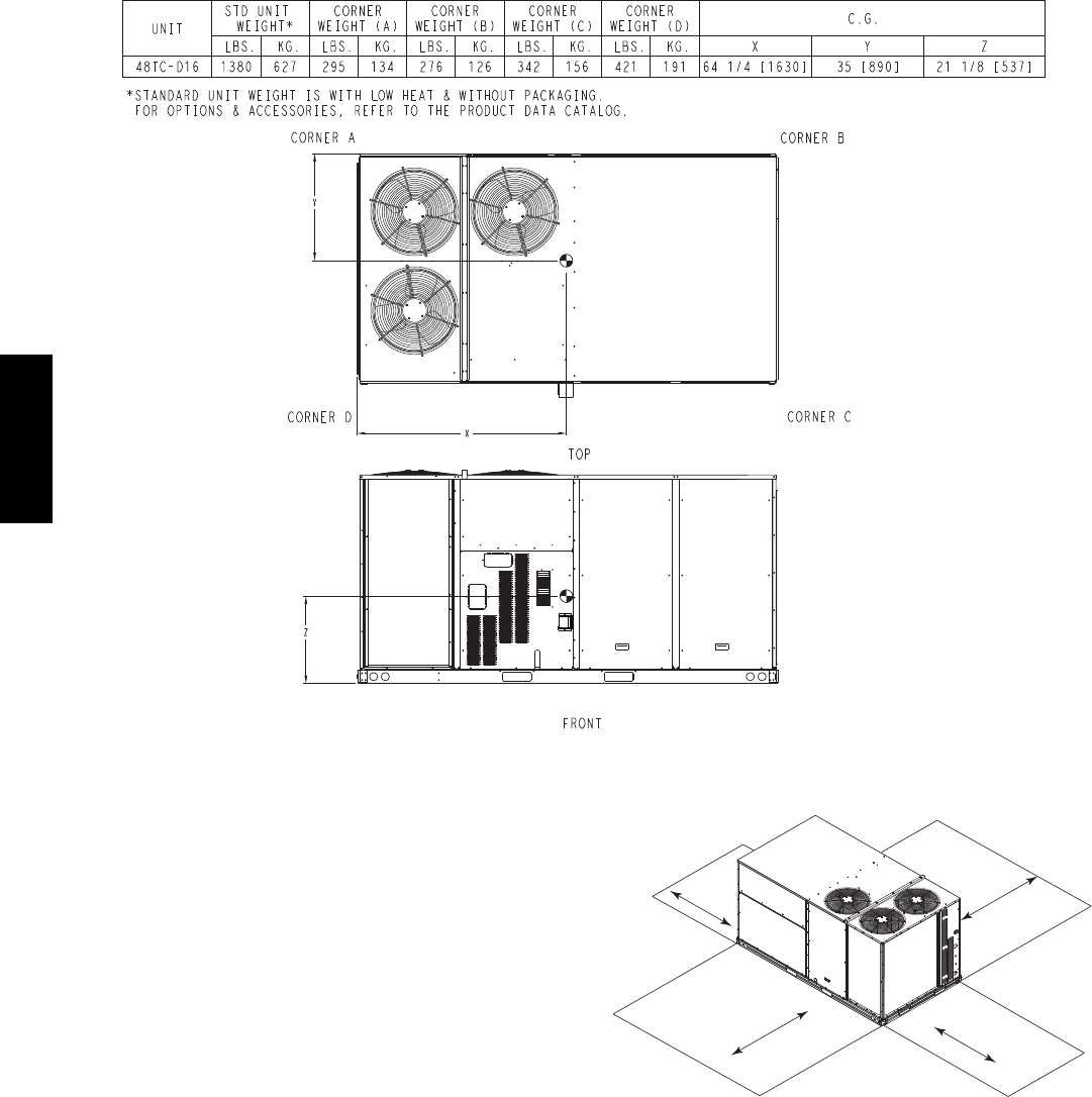
Fig. 1 -- Unit Dimensional Drawing – 16 Size Unit
48TC**16
4
C10862A
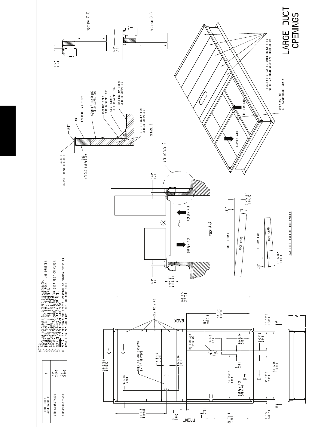
Fig. 1 -- Unit Dimensional Drawing – 16 Size Unit (cont.)
INSTALLATION
Jobsite Survey
Complete the following checks before installation.
1. Consult local building codes and the NEC (National
Electrical Code) ANSI/NFPA 70 for special installa-
tion requirements.
2. Determine unit location (from project plans) or select
unit location.
3. Check for possible overhead obstructions which may
interfere with unit lifting or rigging.
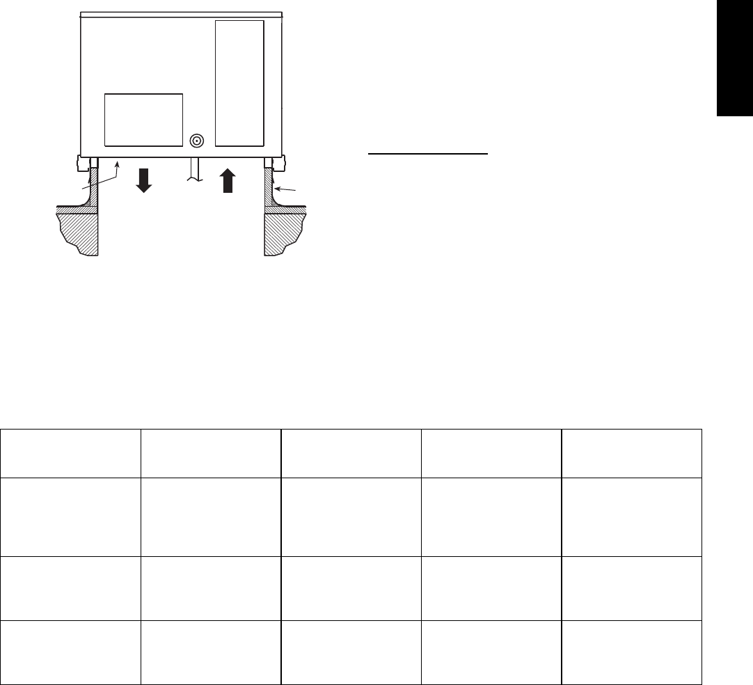
Step 1 — Plan for Unit Location
Select a location for the unit and its support system (curb
or other) that provides for at least the minimum clearances
required for safety. This includes the clearance to
combustible surfaces, unit performance and service access
below, around and above unit as specified in unit
drawings. See Fig. 2.
NOTE: Consider also the effect of adjacent units.
Unit may be installed directly on wood flooring or on Class
A, B, or C roof--covering material when roof curb is used
Do not install unit in an indoor location. Do not locate air
inlets near exhaust vents, relief valves, or other sources of
contaminated air.
18”
(457)
*
42"
(1067)
*
Required bottom condensate drain connection.
Otherwise, 36” (914mm) for condensate connection.
42"
(1067)
42"
(1067)
C09897
Fig. 2 -- Service Clearance Dimensional Drawing
Although unit is weatherproof, avoid locations that permit
water from higher level runoff and overhangs to fall onto
the unit.
Select a unit mounting system that provides adequate
height to allow for removal and disposal of frost and ice
that will form during the heating--defrost mode as well as
allow installation of condensate trap per requirements.
Refer to Step 11 — Install External Condensate Trap and
Line – for required trap dimensions.
48TC**16

5
Roof Mount —
Check building codes for weight distribution
requirements. Unit operating weight is shown in Table 1.
Table 1 – Operating Weights
48TC**16
COMPONENT UNITS LB (KG)
Base Unit 1380 (627)
Economizer
Vertical 100 (45)
Horizontal 115 (52)
H u m i d i --- M i Z e r RSystem 62 (28)
Powered Outlet 32 (15)
Curb
14--- in/356 mm 180 (82)
24--- in/610 mm 235 (107)
Step 2 — Plan for Sequence of Unit Installation
The support method used for this unit will dictate different
sequences for the steps of unit installation. For example,
on curb--mounted units, some accessories must be
installed on the unit before the unit is placed on the curb.
Review the following for recommended sequences for
installation steps.
Curb--mounted installation —
Install curb, making sure to position the common cross
rail (see Fig. 3) for large duct opening.
Install field--fabricated ductwork inside curb
Complete installation of the factory--installed
thru--the--base service connection option
Prepare bottom condensate drain connection to suit
planned condensate line routing (refer to Step 9 for
details)
Rig and place unit
Install outdoor air hood
Install condensate line trap and piping
Make electrical connections
Install other accessories
Pad--mounted installation —
Prepare pad and unit supports
Check and tighten the bottom condensate drain
connection plug
Rig and place unit
Convert unit to side duct connection arrangement
Install field--fabricated ductwork at unit duct openings
Install outdoor air hood
Install condensate line trap and piping
Make electrical connections
Install other accessories
Frame--mounted installation —
Frame--mounted applications generally follow the
sequence for a curb installation. Adapt as required to
suit specific installation plan.
Step 3 — Inspect Unit
Inspect unit for transportation damage. File any claim
with transportation agency.
Confirm before installation of unit that voltage, amperage
and circuit protection requirements listed on unit data
plate agree with power supply provided.
Step 4 — Provide Unit Support
Roof Curb Mount —
Accessory roof curb details and dimensions are shown in
Fig. 3. Assemble and install accessory roof curb in
accordance with instructions shipped with the curb.
NOTE: The gasketing of the unit to the roof curb is
critical for a watertight seal. Install gasket supplied with
the roof curb as shown in Fig. 3. Improperly applied
gasket can also result in air leaks and poor unit
performance.
Curb should be level. This is necessary for unit drain to
function properly. Unit leveling tolerances are show in
Fig. 4. Refer to Accessory Roof Curb Installation
Instructions for additional information as required.
Install insulation, cant strips, roofing felt, and counter
flashing as shown. Ductwork must be attached to curb and
not to the unit.
IMPORTANT:
If the unit’s gas connection and/or electric and control
wiring is to be routed through the basepan and the unit
is equipped with the factory--installed Thru--the--Base
service option see the following sections:
SFactory--Option Thru--Base Connections
(Gas Connection) on page 11
SFactory--Option Thru--Base Connections
(Electrical Connections) on page 17
If using the field--installed Thru--the--Base accessory
follow the instructions provided with the accessory kit.
NOTE: If gas and/or electrical connections are not
going to occur at this time, tape or otherwise cover the
fittings so that moisture does not get into the building or
conduit in the interim.
Slab Mount (Horizontal Units Only) —
Provide a level concrete slab that extends a minimum of
6 in. (150 mm) beyond unit cabinet. Install a gravel apron
in front of condenser coil air inlet to prevent grass and
foliage from obstructing airflow.
NOTE: Horizontal units may be installed on a roof curb
if required.
Alternate Unit Support
(InLieuofCurborSlabMount)—
A non--combustible sleeper rail can be used in the unit curb
support area. If sleeper rails cannot be used, support the long
sides of the unit with a minimum of 3 equally spaced 4--in. x
4--in. (102 mm x 102 mm) pads on each side.
48TC**16
6
C10772
Fig. 3 -- Roof Curb Details
48TC**16
7
A-B
0.5” (13)
B-C
1.0” (25)
A-C
1.0” (25)
MAXIMUM ALLOWABLE
DIFFERENCE IN. (MM)
A
B
C
C10001
Fig. 4 -- Unit Leveling Tolerances
Step 5 — Field Fabricate Ductwork
NOTE: Cabinet return-air static pressure (a negative
condition) shall not exceed 0.35 in. wg (87 Pa) with
economizer or 0.45 in. wg (112 Pa) without economizer.
For vertical ducted applications, secure all ducts to roof curb
and building structure. Do not connect ductwork to unit.
Fabricate supply ductwork so that the cross sectional
dimensions are equal to or greater than the unit supply
duct opening dimensions for the first 18 in. (458 mm) of
duct length from the unit basepan.
Insulate and weatherproof all external ductwork, joints,
and roof openings with counter flashing and mastic in
accordance with applicable codes.
Ducts passing through unconditioned spaces must be
insulated and covered with a vapor barrier.
If a plenum return is used on a vertical unit, the return
should be ducted through the roof deck to comply with
applicable fire codes.
PROPERTY DAMAGE HAZARD
Failure to follow this caution may result in damage
to roofing materials.
Membrane roofs can be cut by sharp sheet metal
edges. Be careful when placing any sheet metal parts
on such roof.
CAUTION
!
Step 6 — Rig and Place Unit
When the unit is ready to be rigged and no longer will be
lifted by a fork truck, the wood protector under the basepan
must be removed. Remove 4 screws from each base rail.
Wood protector will drop to the ground. See instructions on
the unit base rails.
Keep unit upright and do not drop. Spreader bars are
required. Rollers may be used to move unit across a roof.
Level by using unit frame as a reference. See Table 1 and
Fig. 5 for additional information.
Lifting holes are provided in base rails as shown in Fig. 5.
Refer to rigging instructions on unit.
UNIT DAMAGE HAZARD
Failure to follow this caution may result in
equipment damage.
All panels must be in place when rigging. Unit is not
designed for handling by fork truck.
CAUTION
!
Before setting the unit onto the curb, recheck gasketing on
curb.
DETAIL “A”
PLACE ALL SEAL STRIP IN PLACE BEFORE PLACING
UNIT ON ROOF CURB.
DUCT END
SEE DETAIL “A”
914 - 1371
( 36” - 54” )
“B”
“A”
“C”
C10774
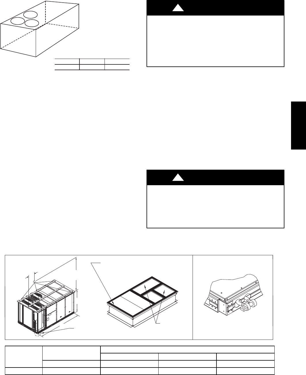
UNIT MAX WEIGHT DIMENSIONS
A B C
LB KG IN MM IN MM IN MM
48TC**16 2130 968 116.0 2945 60.5 1535 59.5 1510
NOTES:
1. SPREADER BARS REQUIRED — Top damage will occur if spreader bars are not used.
2. Dimensions in ( ) are in millimeters.
3. Hook rigging shackles through holes in base rail, as shown in detail “A.” Holes in base rails are centered around
the unit center of gravity. Use wooden top to prevent rigging straps from damaging unit.
Fig. 5 -- Rigging Details
48TC**16
8
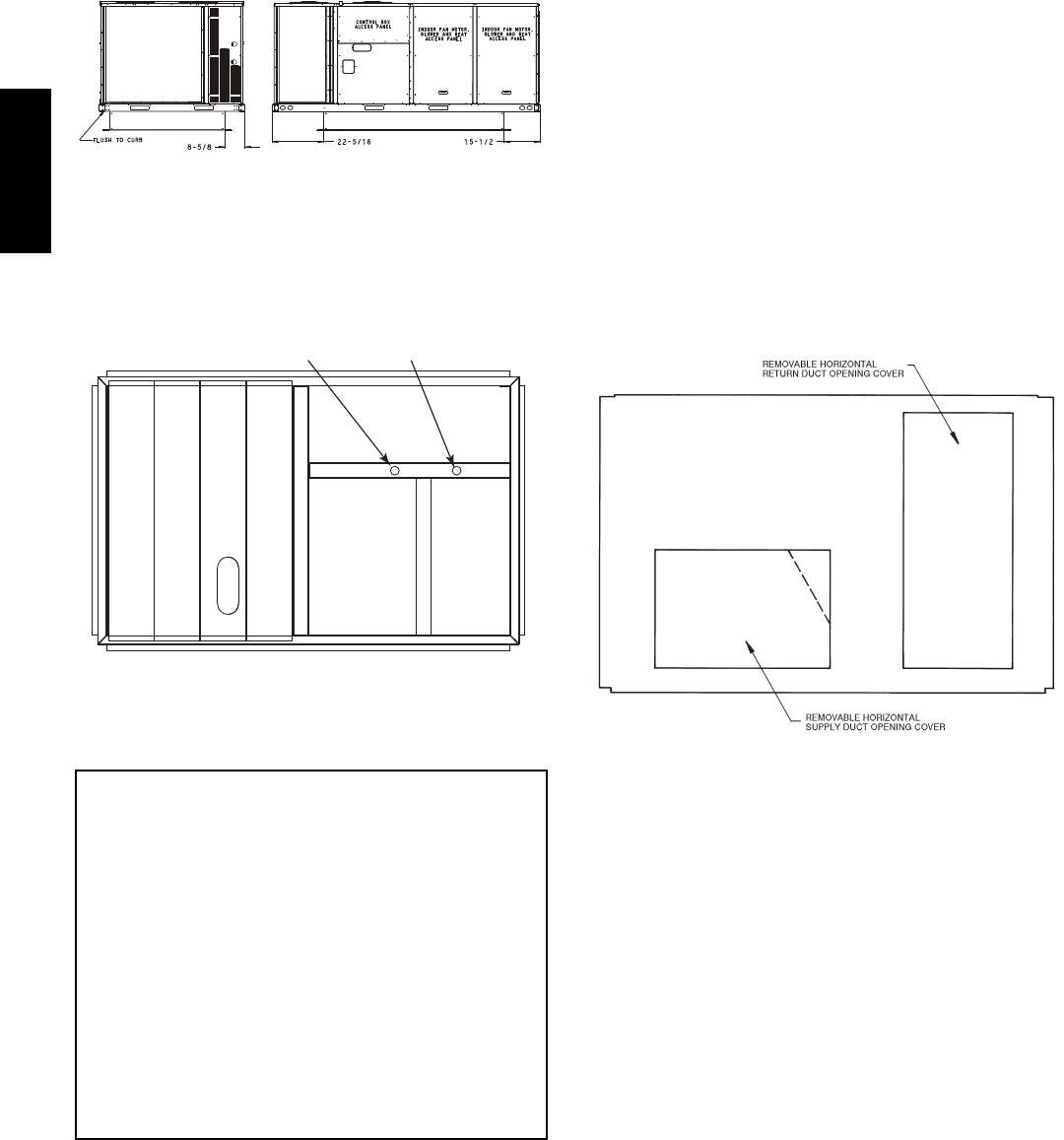
PositioningonCurb—
For full perimeter curbs CRRFCURB074A00 and 075A00,
the clearance between the roof curb and the front and rear
base rails should be 1/4in (6.4 mm). The clearance between
the curb and the end base rails should be 1/2in (13 mm). For
retrofit applications with curbs CRRFCURB003A01 and
4A01, the unit should be position as shown in Fig. 6.
Maintain the 15.5 in (394 mm) and 8 5/8in (220 mm)
clearances and allow the 22 5/16 in (567 mm) dimension to
float if necessary.
C10003
Fig. 6 -- Retrofit Installation Dimensions
If the alternative condensate drain location through the
bottom of the unit is used in conjunction with a retrofit
curb, the hole in the curb must be moved 12.5 in (320
mm) towards the duct end of the unit. (See Fig. 7.)
Original
Position
New Position
(moved 12.5 in.)
C10904
Fig. 7 -- Alternative Condensate Drain Hole Positions
Although unit is weatherproof, guard against water from
higher level runoff and overhangs.
IMPORTANT:
If the unit has the factory--installed Thru--the--Base
option, make sure to complete installation of the option
before placing the unit on the roof curb.
See the following sections:
SFactory--Option Thru--Base Connections
(Gas Connection) on page 11
SFactory--Option Thru--Base Connections
(Electrical Connections) on page 17
NOTE: If gas and/or electrical connections are not
going to occur at this time, tape or otherwise cover the
fittings so that moisture does not get into the building or
conduit in the interim.
Remove all shipping materials and top skid. Remove extra
center post from the condenser end of the unit so that the
condenser end of the unit matches Figs. 26 and 27.
Recycle or dispose of all shipping materials.
Step 7 — Convert to Horizontal and Connect
Ductwork (when required)
Unit is shipped in the vertical duct configuration. Unit
without factory--installed economizer or return air smoke
detector option may be field--converted to horizontal ducted
configuration using accessory CRDUCTCV001A00. To
convert to horizontal configuration, remove screws from side
duct opening covers and remove covers.
Discard the supply duct cover. Install accessory
CRDUCTCV001A00 to cover the vertical supply duct
opening. Use the return duct cover removed from the end
panel to cover the vertical return duct opening.
Field--supplied flanges should be attached to horizontal
duct openings and all ductwork should be secured to the
flanges. Insulate and weatherproof all external ductwork,
joints, and roof or building openings with counter flashing
and mastic in accordance with applicable codes.
Do not cover or obscure visibility to the unit’s informative
data plate when insulating horizontal ductwork.
C06108
Fig. 8 -- Horizontal Conversion Panels
48TC**16
9
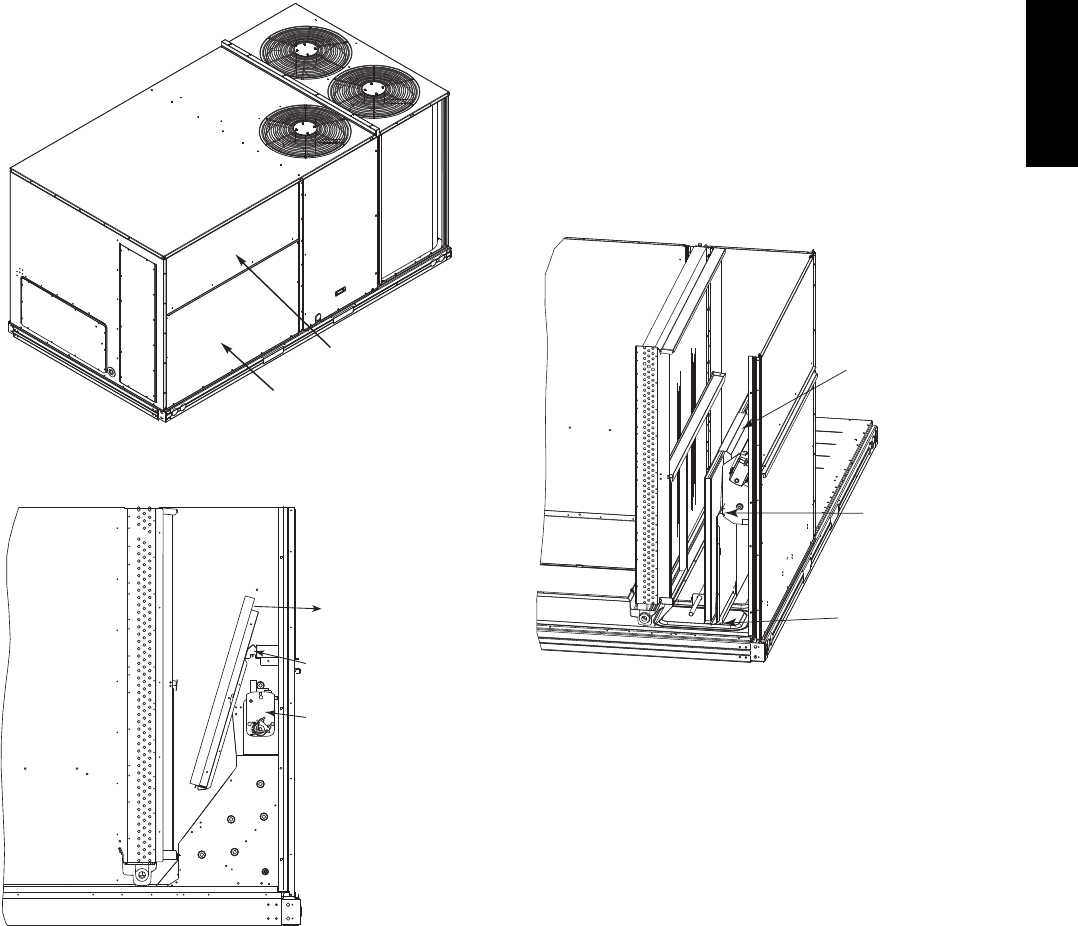
Step 8 — Install Outside Air Hood
Economizer Hood Removal and Setup --
Factory Option —
1. The hood is shipped in knock--down form and located
in the return air compartment. It is attached to the
economizer using two plastic tie--wraps.
2. To gain access to the hood, remove the filter access
panel. (See Fig. 9.)
3. Locate and cut the (2) plastic tie--wraps, being careful
to not damage any wiring. (See Fig. 10.)
4. Carefully lift the hood assembly through the filter
access opening and assemble per the steps outlined in
Economizer Hood and Two–Position Hood on page 10.
FILTER ACCESS PANEL
INDOOR COIL ACCESS PANEL
C10004
Fig. 9 -- Typical Access Panel Locations
Economizer
Cut Plastic Ties
(2) Places
Remove Hood Parts
C10005
Fig. 10 -- Economizer Hood Package Location
Two Position Damper Hood Removal and Setup --
Factory Option —
1. The hood is shipped in knock--down form and
assembled to a metal support tray using plastic stretch
wrap. Located in the return air compartment, the
assembly’s metal tray is attached to the basepan and
also attached to the damper using two plastic
tie--wraps.
2. To gain access to the hood, remove the filter access
panel. (See Fig. 9.)
3. Locate the (2) screws holding the metal tray to the
basepan and remove. In order to remove the screws, it
may be necessary to remove the panel underneath the
two--position damper. Remove the two screws. Locate
and cut the (2) plastic tie--wraps securing the
assembly to the damper. (See Fig. 11.) Be careful to
not damage any wiring or cut tie--wraps securing any
wiring.
4. Carefully lift the hood assembly (with metal tray)
through the filter access opening and assemble per the
steps outlined in Economizer Hood and Two–Position
Hood on page 10.
5. If removed, reattach the panel under the damper.
Hood Parts
Plastic Tie Wrap
Qty (2)
Screws for Metal Tray
Qty (2)
C10006
Fig. 11 -- Two--Position Damper Hood Package Location
48TC**16
10
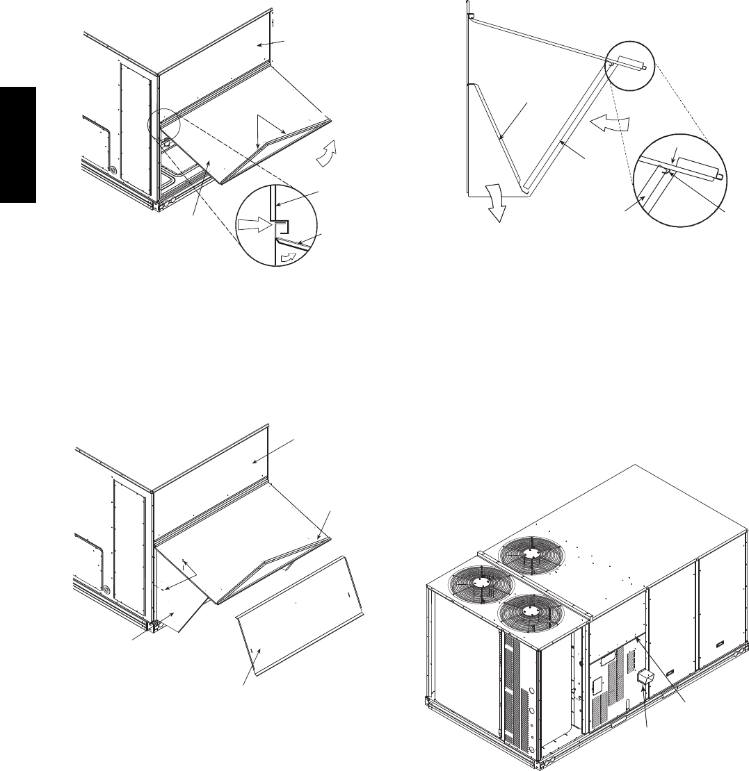
Economizer Hood and Two--Position Hood —
NOTE: If the power exhaust accessory is to be installed
on the unit, the hood shipped with the unit will not be
used and must be discarded. Save the aluminum filter for
use in the power exhaust hood assembly.
1. The indoor coil access panel will be used as the top of
the hood. If the panel is still attached to the unit, re-
move the screws along the sides and bottom of the
panel. See Fig. 12.
SIDE
PANEL
INDOOR
COIL
ACCESS
PANEL
INDOOR
COIL
ACCESS
PANEL
CAULK
HERE
TOP
PANEL
RAIN DEFLECTORS
C10007
Fig. 12 -- Indoor Coil Access Panel Relocation
2. Swing out indoor coil access panel and insert the
hood sides under the panel (hood top). Be careful not
to lift the panel too far as it might fall out. Use the
screws provided to attach the hood sides to the hood
top. Use screws provided to attach the hood sides to
the unit. See Fig. 13.
TOP
PANEL
INDOOR COIL
ACCESS PANEL
SCREW
HOOD DIVIDER
LEFT
HOOD
SIDE
C10008
Fig. 13 -- Economizer Hood Construction
3. Remove the shipping tape holding the economizer
barometric relief damper in place.
4. Insert the hood divider between the hood sides. See
Figs. 13 and 14. Secure hood divider with 3 screws on
each hood side. The hood divider is also used as the
bottom filter rack for the aluminum filter.
5. Attach the post that separates the filters with the
screws provided.
6. Open the filter clips which are located underneath the
hood top. Insert the aluminum filters into the bottom
filter rack (hood divider). Push the filter into position
past the open filter clips. Close the filter clips to lock
the filters into place. See Fig. 14.
7. Install the two rain deflectors on the edge of the hood
topasshowninFig.12.
DIVIDER
BAROMETRIC
RELIEF
CLEANABLE
ALUMINUM
FILTER
FILTER
HOOD
FILTER
CLIP
OUTSIDE
AIR
C10009
Fig. 14 -- Economizer Filter Installation
8. Caulk the ends of the joint between the unit top panel
and the hood top as shown in Fig. 12.
9. Replace the filter access panel.
Step 9 — Install Flue Hood
The flue hood is shipped screwed to the basepan beside
the burner compartment access panel. Remove the panel
below the control box access panel to access the flue hood
shipping location. Using screws provided, install flue
hood and screen in location shown in Fig. 15.
FLUE
HOOD
CONTROL BOX
ACCESS PANEL
C10804
Fig. 15 -- Flue Hood Details
48TC**16
11
Step 10 — Install Gas Piping
Installation of the gas piping must be accordance with
local building codes and with applicable national codes.
In U.S.A., refer to NFPA 54/ANSI Z223.1 National Fuel
Gas Code (NFGC). In Canada, installation must be
accordance with the CAN/CSA B149.1 and CAN/CSA
B149.2 installation codes for gas burning appliances.
This unit is factory equipped for use with Natural Gas fuel
at elevations up to 2000 ft (610 m) above sea level. Unit
may be field converted for operation at elevations above
2000 ft (610 m) and/or for use with liquefied petroleum
fuel. See accessory kit installation instructions regarding
these accessories.
NOTE: In U.S.A. the input rating for altitudes above 2000
ft (610 m) must be derated by 4% for each 1000 ft (305 m)
above sea level. In Canada the input rating must be derated
by 10% for altitudes of 2000 ft (610 m) to 4500 ft. (1372 m)
above sea level.
For natural gas applications, gas pressure at unit gas
connection must not be less than 5 in. wg (1250 Pa) or
greater than 13 in. wg (3240 Pa) while the unit is operating.
For liquified petroleum applications, the gas pressure must
not be less than 11 in. wg (2740 Pa) or greater than 13 in.
wg (3240 Pa) at the unit connection.
The gas supply pipe enters the unit at the burner access
panel on the front side of the unit, through the long slot at
the bottom of the access panel. The gas connection to the
unit is made to the 3/4--in. FPT gas inlet port on the unit gas
valve.
Table 2 – Natural Gas Supply Line Pressure Ranges
UNIT MIN MAX
48HC**14 5.0 in. wg (1250 Pa) 13.0 in. wg (3240 Pa)
EQUIPMENT DAMAGE HAZARD
Failure to follow this caution may result in damage
to equipment.
When connecting the gas line to the unit gas valve,
the installer MUST use a backup wrench to prevent
damage to the valve.
CAUTION
!
Install a gas supply line that runs to the unit heating
section. Refer to the NFPA 54/NFGC or equivalent code
for gas pipe sizing data. Size the gas supply line to allow
for a maximum pressure drop of 0.5--in wg (124 Pa)
between gas regulator source and unit gas valve
connection when unit is operating at high--fire flow rate.
The gas supply line can approach the unit in three ways:
horizontally from outside the unit (across the roof),
thru--curb/under unit basepan (accessory kit required) or
through unit basepan (factory--option or accessory kit
required). Consult accessory kit installation instructions
for details on these installation methods. Observe
clearance to gas line components per Fig. 16.
LEGEND
*Field supplied.
NOTE: Follow all local codes.
NFGC – National Fuel Gas Code
STEEL PIPE
NOMINAL DIAMETER
(in.)
SPACINGOFSUPPORTS
X DIMENSION
(ft)
1/2
3/4or 1
11/4or larger
6
8
10
X
BASE UNIT
BASE RAIL
ROOF
CURB
9” MINIMUM CLEARANCE
FOR PANEL REMOVAL
MANUAL GAS
SHUTOFF VALVE*
GAS
REGULATOR*
48” MINIMUM
DRIP LEG
PER NFGC*
FIELD-
FABRICATED
SUPPORT*
FROM
GAS
METE
R
C11121
Fig. 16 -- Gas Piping Guide
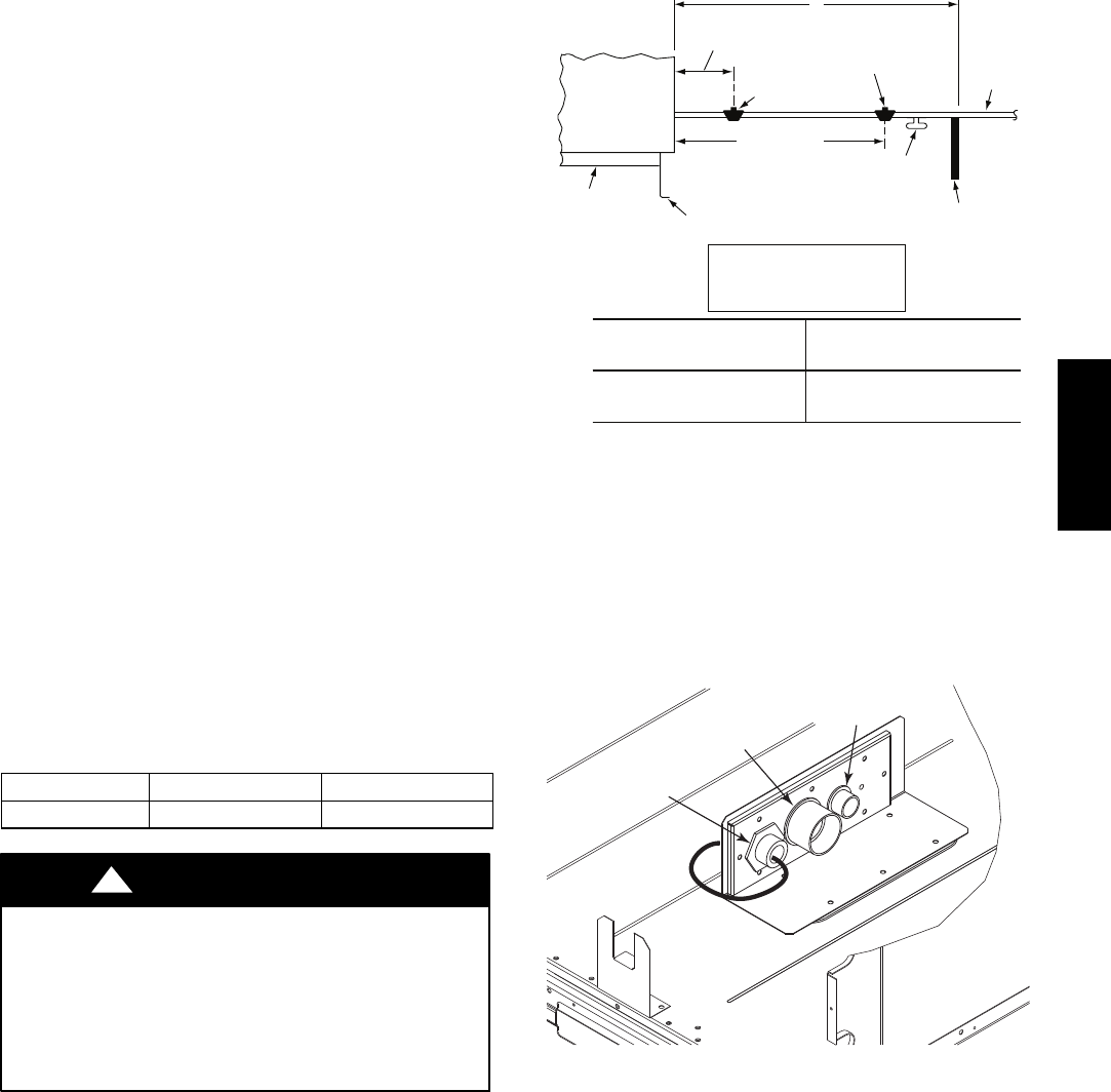
Factory--Option Thru--Base Connections
(Gas Connection) —
This service connection kit consists of a 3/4--in NPT gas adapter
fitting (stainless steel), a 1/2--in electrical bulkhead connector
and a 11/2--in electrical bulkhead connector, connected to an
“L” bracket covering the embossed (raised) section of the unit
basepan in the condenser section. See Fig. 17.
1
1
/
2
” ELECTRICAL
BULKHEAD
CONNECTOR
1
/
2
” ELECTRICAL
BULKHEAD
CONNECTOR
3
/
4
” NPT GAS
ADAPTER
FITTING
C10905
Fig. 17 -- Thru--the--Base Option, Shipping Position
1. Remove the “L” bracket assembly from the unit (see
Fig. 17).
2. Cut and discard the wire tie on the gas fitting. Hand
tighten the fitting if it has loosened in transit.
3. Remove connector plate assembly from the “L”
bracket and discard the “L” bracket, but retain the
washer head screws and the gasket (located between
the “L” bracket and the connector plate assembly
NOTE: Take care not to damage the gasket, as it is
reused in the following step.
4. Place the gasket over the embossed area in the
basepan, aligning the holes in the gasket to the holes
in the basepan. See Fig. 18.
5. Install the connector plate assembly to the basepan
using 8 of the washer head screws.
48TC**16
12
NOTE: If gas and/or electrical connections are not going to
occur at this time, tape or otherwise cover the fittings so that
moisture does not get into the building or conduit in the
interim.
GASKET
CONNECTOR
PLATE
ASSEMBLY
C10906
Fig. 18 -- Completing Installation of Thru--the--Base
Option
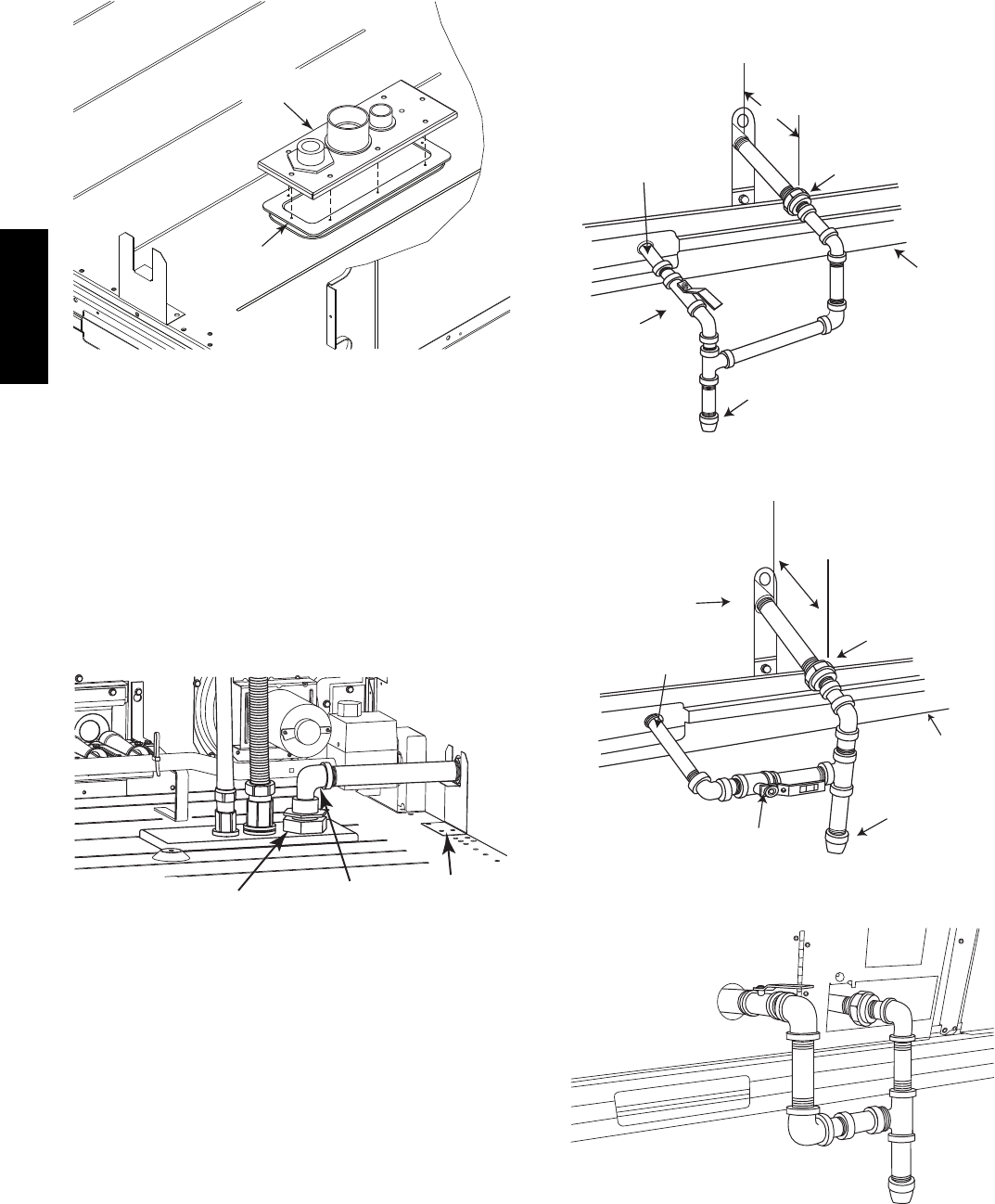
The thru--base gas connector has male and female threads.
The male threads protrude above the basepan of the unit;
the female threads protrude below the basepan.
Check tightness of connector lock nuts before connecting
gas piping.
Install a 3/4--in NPT street elbow (field--supplied) on the
thru--base gas fitting. Attach a 3/4--in pipe nipple with
minimum length of 16--in (406 mm) (field--supplied) to
the street elbow and extend it through the access panel at
the gas support bracket. (See Fig. 19.)
3
/
4
-in NPT
STREET
ELBOW
THRU-BASE
GAS FITTING
GAS
SUPPORT
BRACKET
C10806
Fig. 19 -- Gas Line Piping
Other hardware required to complete the installation of
the gas supply line will include a manual shutoff valve, a
sediment trap (drip leg) and a ground--joint union. A
pressure regulator valve may also be required (to convert
gas pressure from pounds to inches of pressure). The
manual shutoff valve must be located within 6--ft (1.83 m)
of the unit. The union, located in the final leg entering the
unit, must be located at least 9--in (230 mm) away from
the access panel to permit the panel to be removed for
service. If a regulator valve is installed, it must be located
a minimum of 4--ft (1220 mm) away from the unit’s flue
outlet. Some municipal codes require that the manual
shutoff valve be located upstream of the sediment trap.
See Figs. 20 and 21 for typical piping arrangements for
gas piping that has been routed through the sidewall of the
curb. See Fig. 22 for typical piping arrangement when
thru--base is used. Ensure that all piping does not block
access to the unit’s main control box or limit the required
working space in front of the control box.
9” (229mm) min
Union
Shut Off
Valve
Drip
Leg
Thru-Curb Adapter
Unit Base Rail
C07469
Fig. 20 -- Gas Piping
Drip
Leg
Shut Off
Valve
Union
Thru-Curb Adapter
Burner
Access
Panel
9” (229mm) min
Unit Base Rail
C07470
Fig. 21 -- Gas Piping
C10826
Fig. 22 -- Gas Piping Thru--Base Connections
48TC**16
13
When installing the gas supply line, observe local codes
pertaining to gas pipe installations. Refer to the NFPA
54/ANSI Z223.1 NFGC latest edition (in Canada, CAN/CSA
B149.1). In the absence of local building codes, adhere to
the following pertinent recommendations:
1. Avoid low spots in long runs of pipe. Grade all pipe
1/4--in. in every 15 ft (7 mm in every 5 m) to prevent
traps. Grade all horizontal runs downward to risers.
Use risers to connect to heating section and to meter.
2. Protect all segments of piping system against physical
and thermal damage. Support all piping with appro-
priate straps, hangers, etc. Use a minimum of one
hanger every 8 ft (2.4 m). For pipe sizes larger than
3/4--in., follow recommendations of national codes.
3. Apply joint compound (pipe dope) sparingly and only
to male threads of joint when making pipe connec-
tions. Use only pipe dope that is resistant to action of
liquefied petroleum gases as specified by local and/or
national codes. If using PTFE (Teflon) tape, ensure
the material is Double Density type and is labeled for
use on gas lines. Apply tape per manufacturer’s in-
structions.
4. Pressure--test all gas piping in accordance with local
and national plumbing and gas codes before connect-
ing piping to unit.
NOTE: Pressure test the gas supply system after the gas
supply piping is connected to the gas valve. The supply
piping must be disconnected from the gas valve during the
testing of the piping systems when test pressure is in
excess of 0.5 psig (3450 Pa). Pressure test the gas supply
piping system at pressures equal to or less than 0.5 psig
(3450 Pa). The unit heating section must be isolated from
the gas piping system by closing the external main manual
shutoff valve and slightly opening the ground--joint union.
Check for gas leaks at the field--installed and
factory--installed gas lines after all piping connections
have been completed. Use soap--and--water solution (or
method specified by local codes and/or regulations).
FIRE OR EXPLOSION HAZARD
Failure to follow this warning could result in personal
injury, death and/or property damage.
SConnect gas pipe to unit using a backup wrench to
avoid damaging gas controls.
SNever purge a gas line into a combustion chamber.
SNever test for gas leaks with an open flame. Use a
commercially available soap solution made
specifically for the detection of leaks to check all
connections.
SUse proper length of pipe to avoid stress on gas
control manifold.
!WARNING
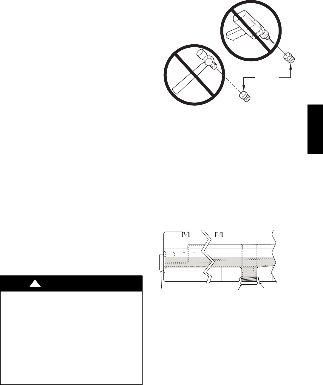
BURNER
ORIFICE
A93059
Fig. 23 -- Orifice Hole
NOTE: If orifice hole appears damaged or it is suspected
to have been re--drilled, check orifice hole with a
numbered drill bit of correct size. Never re--drill an
orifice. A burr--free and squarely aligned orifice hole is
essential for proper flame characteristics. See Fig. 23.
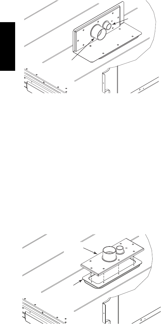
Step 11 — Install External Condensate Trap and
Line
The unit has one 3/4-in. condensate drain connection on
the end of the condensate pan and an alternate connection
on the bottom. See Fig. 24. Unit airflow configuration
does not determine which drain connection to use. Either
drain connection can be used with vertical or horizontal
applications.
DRAIN
(FACTORY-INSTALLED)
PLUG
CONDENSATE PAN (SIDE VIEW)
STANDARD
SIDE DRAIN
ALTERNATE
BOTTOM DRAIN
C08021
Fig. 24 -- Condensate Drain Pan (Side View)
When using the standard side drain connection, ensure the
red plug in the alternate bottom connection is tight. Do
this before setting the unit in place. The red drain pan can
be tightened with a 1/2--in. square socket drive extension.
To use the alternate bottom drain connection, remove the
red drain plug from the bottom connection (use a 1/2-- i n .
square socket drive extension) and install it in the side
drain connection.
48TC**16
14
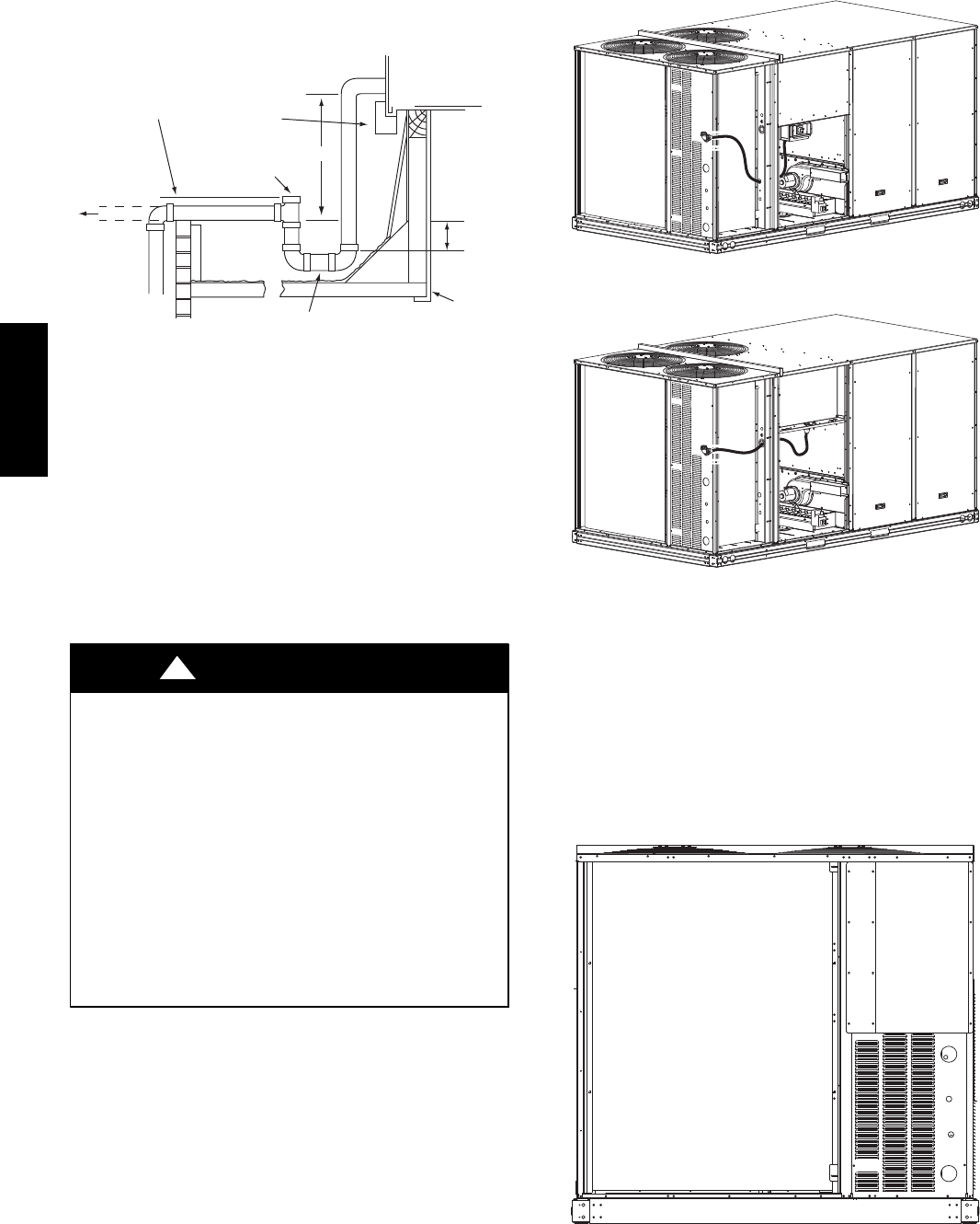
The piping for the condensate drain and external trap can
be completed after the unit is in place. See Fig. 25.
NOTE: Trap should be deep enough to offset maximum unit static
difference. A 4” (102) trap is recommended.
MINIMUM PITCH
1” (25mm) PER
10’ (3m) OF LINE BASE RAIL
OPEN
VENT
TO ROOF
DRAIN
DRAIN PLUG
ROOF
CURB
SEE NOTE
2˝ (51) MIN
C08022
Fig. 25 -- Condensate Drain Piping Details
All units must have an external trap for condensate
drainage. Install a trap at least 4-in. (102 mm) deep and
protect against freeze-up. If drain line is installed
downstream from the external trap, pitch the line away
from the unit at 1-in. per 10 ft (25 mm in 3 m) of run. Do
not use a pipe size smaller than the unit connection
(3/4-in.).
Step 12 — Make Electrical Connections
ELECTRICAL SHOCK HAZARD
Failure to follow this warning could result in personal
injury or death.
Do not use gas piping as an electrical ground. Unit
cabinet must have an uninterrupted, unbroken electrical
ground to minimize the possibility of personal injury if
an electrical fault should occur. This ground may consist
of electrical wire connected to unit ground lug in control
compartment, or conduit approved for electrical ground
when installed in accordance with NEC (National
Electrical Code); ANSI/NFPA 70, latest edition (in
Canada, Canadian Electrical Code CSA [Canadian
Standards Association] C22.1), and local electrical
codes.
!WARNING
NOTE: Field--supplied wiring shall conform with the
limitations of minimum 63_F(33_C) rise.
Field Power Supply —
For those units without through--the--curb power, conduit
must be used to route the main power from the condenser
end, via the power entry in the corner post of the unit (see
Figs. 26 and 27) to either the factory option disconnect or
the bottom of the control box. 1” conduit is provided
wrapped around compressor. A second conduit is provided
with factory installed powered convenience outlet. For those
units that require conduit larger than 1”, it must be field
supplied. Figs. 26 and 27 show the wire routings.
C10884
Fig. 26 -- Conduit into Factory Option Disconnect
C10885
Fig. 27 -- Conduit into Control Box
If the field disconnect is larger than 100A, it must be
attached to the unit using accessory CRDISBKT001A00
— disconnect switch bracket — (see Fig. 28). Follow the
instructions provided with this accessory. For smaller field
disconnects, be sure to use 1/2” screws to mount the
disconnect directly to the end panel (see Fig. 29). In either
case, set the disconnect vertical location on the unit so
that a 90_fitting can be used to connect the conduit to the
disconnect.
C10853
Fig. 28 -- Mounting Position for Field Disconnects
(over 100A)
48TC**16
15
C10854
Fig. 29 -- Mounting Position for Field Disconnects
(up to 100A)
Field power wires are connected to the unit at line--side
pressure lugs at the main terminal block (TB1) or at
factory--installed option non--fused disconnect switch.
Max wire size is #2 AWG (copper only). (See Fig. 31.)
NOTE: TEST LEADS -- Unit may be equipped with
short leads (pigtails) on the field line connection points off
the optional disconnect switch. These leads are for factory
run--test purposes only; remove and discard before
connecting field power wires to unit connection points.
Make field power connections directly to line connection
pressure lugs only.
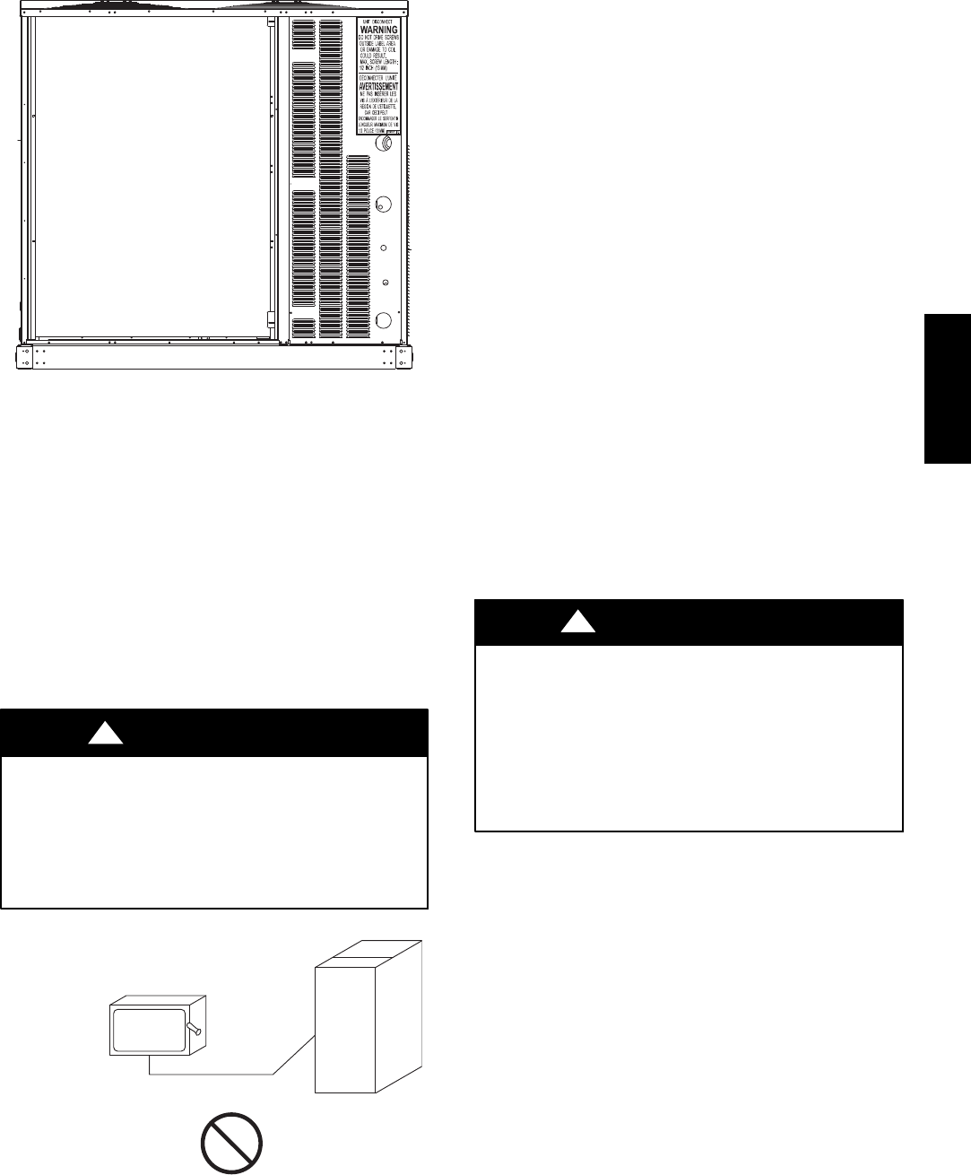
FIRE HAZARD
Failure to follow this warning could result in
intermittent operation or performance satisfaction.
Do not connect aluminum wire between disconnect
switch and unit. Use only copper wire.
(See Fig. 30.)
!WARNING
COPPER
WIRE ONLY
ELECTRIC
DISCONNECT
SWITCH
ALUMINUM
WIRE
A93033
Fig. 30 -- Disconnect Switch and Unit
All Units —
All field wiring must comply with NEC and all local
requirements. Size wire based on MCA (Minimum Circuit
Amps) on the unit informative plate. See Fig. 31 and the
unit label diagram for power wiring connections to the
unit power terminal blocks and equipment ground.
Maximum wire size is 2/0 AWG per pole.
Provide a ground--fault and short--circuit over--current
protection device (fuse or breaker) per NEC Article 440
(or local codes). Refer to unit informative data plate for
MOCP (Maximum Over--current Protection) device size.
Voltage to compressor terminals during operation must be
within voltage range indicated on unit nameplate. See
Table 10. On 3--phase units, voltages between phases must
be balanced within 2% and the current within 10%. Use
the formula shown in the legend for Table 10 (see Note 2
on page 45) to determine the percent of voltage
imbalance.
All units except 208/230-v units are factory wired for the
voltage shown on the nameplate. If the 208/230-v unit is
to be connected to a 208-v power supply, the control
transformer must be rewired by moving the black wire
with the 1/4-in. female spade connector from the 230--v
connection and moving it to the 200-v 1/4-in. male
terminal on the primary side of the transformer. Refer to
unit label diagram for additional information.
UNIT DAMAGE HAZARD
Failure to follow this caution may result in equipment
damage.
Operation on improper line voltage or excessive phase
imbalance constitutes abuse and may cause damage to
electrical components. Such operation would invalidate
any applicable Carrier warranty.
CAUTION
!
NOTE: Check all factory and field electrical connections
for tightness.
Units Without Factory--Installed Disconnect —
When installing units, provide a disconnect switch of
adequate size per NEC (National Electrical Code).
Disconnect sizing data is provided on the unit informative
plate. Locate on unit cabinet or within sight of the unit per
national or local codes. Do not cover unit informative
plate if mounting the disconnect on the unit cabinet.
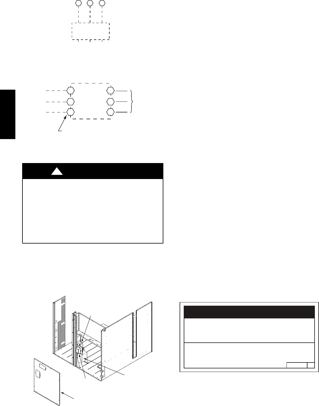
Units with Factory--Installed Disconnect —
The factory--installed option disconnect switch is located in a
weatherproof enclosure located under the main control box.
The manual switch handle is accessible through an opening
in the access panel. Discard the factory test leads (see Fig.
31). The factory disconnect is an 80A disconnect.
48TC**16
16
Units Without Disconnect Option
Units With Disconnect Option
2
4
6
1
3
5
L1
L2
L3
Optional
Disconnect
Switch
Disconnect factory test leads; discard.
Factory
Wiring
11 12 13
L1 L2 L3
TB1
208/230-3-60
460-3-60
575-3-60
Disconnect
per
NEC
C10015
Fig. 31 -- Power Wiring Connections
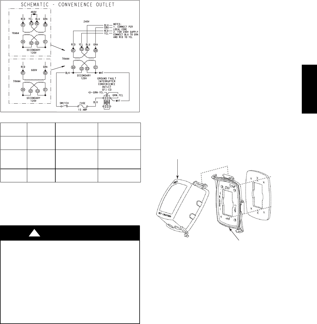
Convenience Outlets —
ELECTRICAL OPERATION HAZARD
Failure to follow this warning could result in personal
injury or death.
Units with convenience outlet circuits may use
multiple disconnects. Check convenience outlet for
power status before opening unit for service. Locate
its disconnect switch, if appropriate, and open it.
Lock--out and tag--out this switch, if necessary.
!WARNING
Two types of convenience outlets are offered on the
48TC**16 : non--powered and unit--powered. Both types
provide a 125--volt GFCI (ground--fault circuit--interrupter)
duplex receptacle rated at 15--A behind a hinged waterproof
access cover, located on the panel beneath the control box.
See Fig. 32.
Convenience
Outlet
GFCI
Pwd-CO
Fuse
Switch
Pwd-CO
Transformer
Disconnect
Access Panel
C10361
Fig. 32 -- Convenience Outlet Location
Non--powered type: This type requires the field
installation of a general--purpose 125--volt 15--A circuit
powered from a source elsewhere in the building. Observe
national and local codes when selecting wire size and
conduit requirements, fuse or breaker requirements and
disconnect switch size and location. Route 125--v power
supply conductors into the bottom of the utility box
containing the duplex receptacle.
Unit--powered type: A unit--mounted transformer is
factory--installed to stepdown the main power supply
voltage to the unit to 115--v at the duplex receptacle. This
option also includes a manual switch with fuse, located in
a utility box and mounted on a bracket behind the
convenience outlet; access is through the panel beneath
the control box. See Fig. 32.
The primary leads to the convenience outlet transformer
are not factory--connected. Selection of primary power
source is a customer--option. If local codes permit, the
transformer primary leads can be connected at the
line--side terminals on the unit--mounted non--fused
disconnect; this will provide service power to the unit
when the unit disconnect switch is open. Other connection
methods will result in the convenience outlet circuit being
de--energized when the unit disconnect switch is open. See
Fig. 34. On a unit without a unit--mounted disconnect,
connect the source leads to the main terminal block
(TB1).
If the convenience outlet transformer is connected to the
line side of a field disconnect, the conduit provided with
the unit must be used to protect the wire as they are routed
from the transformer to the field disconnect. The end of
the conduit with the straight connector attaches to the
field disconnect. The other end does not need to connect
to the transformer; however, the conduit must be routed so
that all wiring is either in the conduit or behind the access
panel.
If the convenience outlet transformer is connected to the
line side of the factory disconnect option, route the wires
through the web bushing located on the bottom of the
disconnect box. For the load side wiring to the factory
option disconnect, route the wires through the hole on the
right side of the disconnect. Be sure to create a drip loop
at least 6” long.
2.050HE501288
NOTICE/AVIS
Convenience Outlet Utilization
Maximum Intermittent Use 15 - Amps
Maximum Continuous Use 8 - Amps
Observe a 50% limit on the circuit
Loading above 8 - Amps
Utilisation de la prise utilitaire
Usage intermittent maximum 15 - Amps
Usage continu maximum 8 - Amps
Observez une limite de 50% sur le circuit
Chargement au-dessus de 8 - Amps
C10077
Fig. 33 -- Convenience Outlet Utilization Notice
48TC**16
17
Test the GFCI receptacle by pressing the TEST button on
the face of the receptacle to trip and open the receptacle.
Check for proper grounding wires and power line phasing
if the GFCI receptacle does not trip as required. Press the
RESET button to clear the tripped condition.
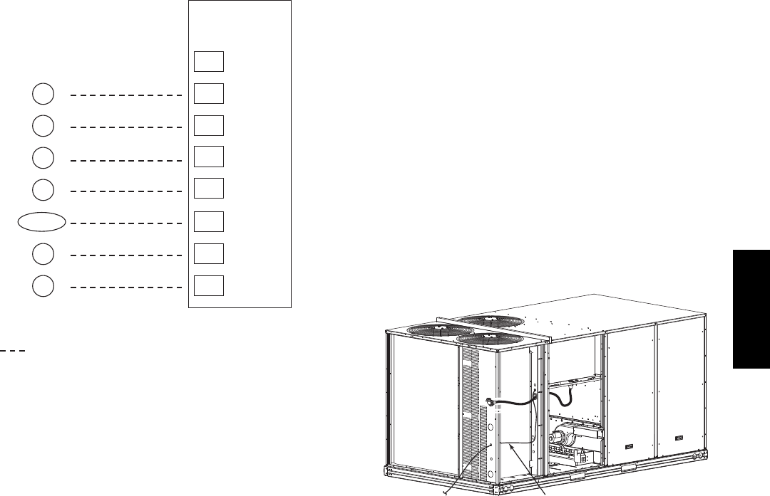
C08283
UNIT
VOLTAGE
CONNECT
AS
PRIMARY
CONNECTIONS
TRANSFORMER
TERMINALS
208,
230 240 L1: RED +YEL
L2: BLU + GRA
H1 + H3
H2 + H4
460 480
L1: RED
Splice BLU + YEL
L2: GRA
H1
H2 + H3
H4
575 600 L1: RED
L2: GRA
H1
H2
Fig. 34 -- Unit Powered Convenience Outlet Wiring
Fuse on power type: The factory fuse is a Bussman
“Fusetron” T--15, non--renewable screw--in (Edison base)
type plug fuse.
ELECTRICAL OPERATION HAZARD
Failure to follow this warning could result in personal
injury or death.
Using unit--mounted convenience outlets: Units with
unit--mounded convenience outlet circuits will often
require that two disconnects be opened to de--energize
all power to the unit. Treat all units as electrically
energized until the convenience outlet power is also
checked and de--energization is confirmed. Observe
National Electrical Code Article 210, Branch Circuits,
for use of convenience outlets.
!WARNING
Installing Weatherproof Cover: A weatherproof
while-in-use cover for the factory-installed convenience
outlets is now required by UL standards. This cover cannot
be factory-mounted due its depth; it must be installed at unit
installation. For shipment, the convenience outlet is covered
with a blank cover plate.
The weatherproof cover kit is shipped in the unit’s control
box. The kit includes the hinged cover, a backing plate and
gasket.
DISCONNECT ALL POWER TO UNIT AND
CONVENIENCE OUTLET. LOCK--OUT AND TAG--OUT
ALL POWER.
Remove the blank cover plate at the convenience outlet;
discard the blank cover.
Loosen the two screws at the GFCI duplex outlet, until
approximately 1/2-in (13 mm) under screw heads are
exposed. Press the gasket over the screw heads. Slip the
backing plate over the screw heads at the keyhole slots
and align with the gasket; tighten the two screws until
snug (do not over-tighten).
Mount the weatherproof cover to the backing plate as
shown in Fig. 35. Remove two slot fillers in the bottom of
the cover to permit service tool cords to exit the cover.
Check for full closing and latching.
RECEPTACLE
NOT INCLUDED
COVER – WHILE-IN-USE
WEATHERPROOF
BASE PLATE FOR
GFCI RECEPTACLE
C09022
Fig. 35 -- Weatherproof Cover Installation
48TC**16
18
Factory--Option Thru--Base Connections
(Electrical Connections)—
This service connection kit consists of a 1/2--in electrical
bulkhead connector and a 11/2--in electrical bulkhead
connector, connected to an “L” bracket covering the
embossed (raised) section of the unit basepan in the
condenser section. See Fig. 36. The 1/2--in bulkhead
connector enables the low--voltage control wires to pass
through the basepan. The 11/2--in electrical bulkhead
connector allows the high--voltage power wires to pass
through the basepan.
1
/
2
” ELECTRICAL
BULKHEAD
CONNECTOR
1
1
/
2
” ELECTRICAL
BULKHEAD
CONNECTOR
C10907
Fig. 36 -- Thru--the--Base Option, Shipping Position
1. Remove the “L” bracket assembly from the unit.
2. Remove connector plate assembly from the “L”
bracket and discard the “L” bracket, but retain the
washer head screws and the gasket (located between
the “L” bracket and the connector plate assembly).
NOTE: Take care not to damage the gasket, as it is
reused in the following step.
3. Place the gasket over the embossed area in the
basepan, aligning the holes in the gasket to the holes
in the basepan. See Fig. 37.
4. Install the connector plate assembly to the basepan
using 8 of the washer head screws.
NOTE: If electrical connections are not going to occur at
this time, tape or otherwise cover the fittings so that
moisture does not get into the building or conduit in the
interim.
GASKET
CONNECTOR
PLATE
ASSEMBLY
C10908
Fig. 37 -- Completing Installation of Thru--the--Base
Option
Check tightness of connector lock nuts before connecting
electrical conduits.
Field--supplied and field--installed liquid tight conduit
connectors and conduit may be attached to the connectors
on the basepan. Pull correctly rated high voltage and low
voltage through appropriate conduits. Connect the power
conduit to the internal disconnect (if unit is so equipped)
or to the external disconnect (through unit side panel). A
hole must be field cut in the main control box bottom on
the left side so the 24--v control connections can be made.
Connect the control power conduit to the unit control box
at this hole.
Units without Thru--Base Connections —
1. Install power wiring conduit through side panel open-
ings. Install conduit between disconnect and control
box.
2. Install power lines to terminal connections as shown
in Fig. 31.
Field Control Wiring —
The 48TC**16 requires an external temperature control
device. This device can be a thermostat (field--supplied)
or a PremierLink controller (available as factory--installed
option or as field--installed accessory, for use on a Carrier
Comfort Network or as a stand alone control) or the RTU
Open Controller for Building Management Systems using
non--CCN protocols (RTU Open is available as a
factory--installed option only).
Thermostat —
Install a Carrier--approved accessory 2 stage
Cooling/Heating thermostat according to installation
instructions included with the accessory. If using an
electronic thermostat, configure it for “non--heat pump”
operation. Locate the thermostat accessory on a solid wall
in the conditioned space to sense average temperature in
accordance with the thermostat installation instructions.
If the thermostat contains a logic circuit requiring 24--v
power, use a thermostat cable or equivalent single leads of
different colors with minimum of seven leads. If the
thermostat does not require a 24--v source (no “C”
connection required), use a thermostat cable or equivalent
with minimum of six leads. Check the thermostat
installation instructions for additional features which
might require additional conductors in the cable.
For wire runs up to 50 ft. (15 m), use no. 18 AWG
(American Wire Gage) insulated wire (35_C minimum).
For50to75ft.(15to23m),useno.16AWGinsulated
wire (35_C minimum). For over 75 ft. (23 m), use no. 14
AWG insulated wire (35_C minimum). All wire sizes
larger than no. 18 AWG cannot be directly connected to
the thermostat and will require a junction box and splice
at the thermostat.
48TC**16
19
X
C
G
W2
C
W2
G
W1
O/B/Y2 Y2
R
W1
R
Y1 Y1
T
H
E
R
M
O
S
T
A
T
(see Note)
Note: Typical multi-function marking. Follow manufacturer’s configuration
instructions to select Y2. Do not configure for O output.
Field Wiring
Central
Terminal
Board
Typical
Thermostat
Connections
C10903
Fig. 38 -- Typical Low--Voltage Control Connections
Unit without Thru--Base Connection Kit —
Pass the thermostat control wires through the bushing on the
unit end panel. Route the wire through the snap--in wire tie
and up to the web bushing near the control box.. Route the
wire through the bushing and into the bottom left side of the
control box after removing one of the two knockouts in the
corner of the box. Use a connector at the control box to
protect the wire as it passes into the control box. Pull the
wires over to the terminal strip at the upper left corner of the
Central Terminal Board (CTB). Use the connector at the
control box and the wire tie to take up any slack in the
thermostat wire to ensure that it will not be damaged by
contact with the condenser coil. See Fig. 39.
NOTE: If thru--the--bottom connections accessory is
used, refer to the accessory installation instructions for
information on routing power and control wiring.
Thermostat Wire
C10886
Fig. 39 -- Thermostat Wire Routing
Heat Anticipator Settings —
Set heat anticipator settings at 0.14 amp for the first stage
and 0.14 amp for second--stage heating, when available.
48TC**16
20
Humidi--MiZerRControl Connections
Humidi--MiZer – Space RH Controller —
NOTE: The Humidi--MiZer is a factory installed option.
The Humidi--MiZer dehumidification system requires a
field--supplied and --installed space relative humidity
control device. This device may be a separate humidistat
control (contact closes on rise in space RH above control
setpoint) or a combination thermostat--humidistat control
device such as Carrier’s EDGERPro Thermidistat with
isolated contact set for dehumidification control. The
humidistat is normally used in applications where a
temperature control is already provided (units with
PremierLinktcontrol).
To connect the Carrier humidistat (HL38MG029):
1. Route the humidistat 2--conductor cable (field--supplied)
through the bushing the unit’s louvered end panel (see
Fig. 39).
2. Route the cable through the snap--in wire tie and up to
the web bushing near the control box.
3. Feed the cable through the bushing and into the
bottom left side of the control box after removing one
of the two knockouts in the corner of the box. Use a
connector to protect the cable as it enters the control
box.
4. Use the connector and the wire tie to reduce any slack
in the humidistat cable to ensure that it will not be
damaged by contact with the condenser coil (see Fig.
39).
5. Use wire nuts to connect humidistat cable to two
PINK leads in the low–voltage wiring as shown in
Fig. 42.
To connect the Thermidistat device (33CS2PPRH--01):
1. Route the Thermidistat multi--conductor thermostat
cable (field--supplied) through the bushing the unit’s
louvered end panel (see Fig. 39).
2. Route the cable through the snap--in wire tie and up to
the web bushing near the control box.
3. Feed the cable through the bushing and into the
bottom left side of the control box after removing one
of the two knockouts in the corner of the box. Use a
connector to protect the cable as it enters the control
box.
4. Use the connector and the wire tie to reduce any slack
in the thermostat cable to ensure that it will not be
damaged by contact with the condenser coil (see Fig.
39).
5. The Thermidistat has dry contacts at terminals D1
and D2 for dehumidification operation (see Fig. 43).
The dry contacts must be wired between CTB
terminal R and the PINK lead to the LTLO switch
with field--supplied wire nuts. Refer to the installation
instructions included with the Carrier Edge
Thermidistat device (Form 33CS--65SI or latest) for
more information.
% RELATIVE HUMIDITY
C09295
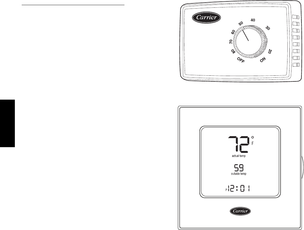
Fig. 40 -- Accessory Field--Installed Humidistat
®
C09296
Fig. 41 -- EDGE Pro Thermidistat
48TC**16
21
HUMIDISTAT
C11201
Fig. 42 -- Typical Humidi--MiZerRAdaptive Dehumidification System Humidistat Wiring
Rc
Rh
W1
G
Y2
C
O/W2/B
Y1
OAT
RRS
SRTN
HUM
D1
D2
V+
Vg
X*
C
G
W2
W1
Y2
Y1
R
EDGE Pro THERMIDISTAT Unit CTB
THERMOSTAT
*Connection not required.
Humidi-MiZer™ FIOP
C09298
Fig. 43 -- Typical Rooftop Unit with Humidi--MiZer Adaptive Dehumidification System
with EDGE Pro Thermidistat Device
48TC**16
22
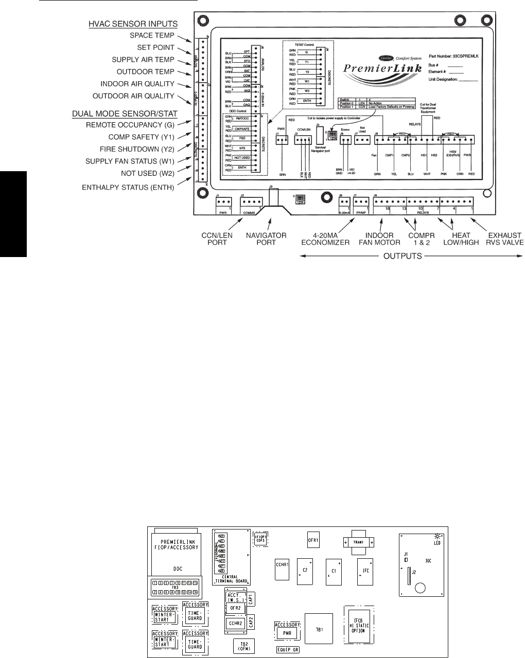
PremierLinkt(Factory Option)
C08199
Fig. 44 -- PremierLink Controller
NOTE: Refer to Form 33CS--67SI for complete
PremierLink configuration, operating sequences and
troubleshooting information. Have a copy of this manual
available at unit start--up.
The PremierLink controller (see Fig. 44) is compatible
with Carrier Comfort Networkr(CCN) devices. This
control is designed to allow users the access and ability to
change factory--defined settings, thus expanding the
function of the standard unit control board. CCN service
access tools include System Pilot (TM), Touch Pilot (TM)
and Service Tool. (Standard tier display tools Navigatort
and Scrolling Marquee are not suitable for use with latest
PremierLink controller (Version 2.x).)
The PremierLink control is factory--mounted in the
48TC**16 unit’s main control box to the left of the
Central Terminal Board (CTB) (see Fig. 45). Factory
wiring is completed through harnesses connected to the
CTB. Field connections are made at a 16--pole terminal
block (TB3) located on the bottom shelf of the unit
control box in front of the PremierLink controller. The
factory--installed PremierLink control includes the
supply--air temperature (SAT) sensor. The outdoor air
temperature (OAT) sensor is included in the
FIOP/accessory EconoMi$ert2 package. (See page 34 for
accessory enthalpy controls.)
The PremierLink controller requires the use of a Carrier
electronic thermostat or a CCN connection for time
broadcast to initiate its internal timeclock. This is
necessary for broadcast of time of day functions
(occupied/unoccupied).
NOTE: PremierLink controller is shipped in Sensor mode.
To be used with a thermostat, the PremierLink controller
must be configured to Thermostat mode. Refer to
PremierLink Configuration instructions for Operating Mode.
C11189
Fig. 45 -- 48HC**14 Control Box Component Locations -- PremierLink Controller Location
48TC**16
23
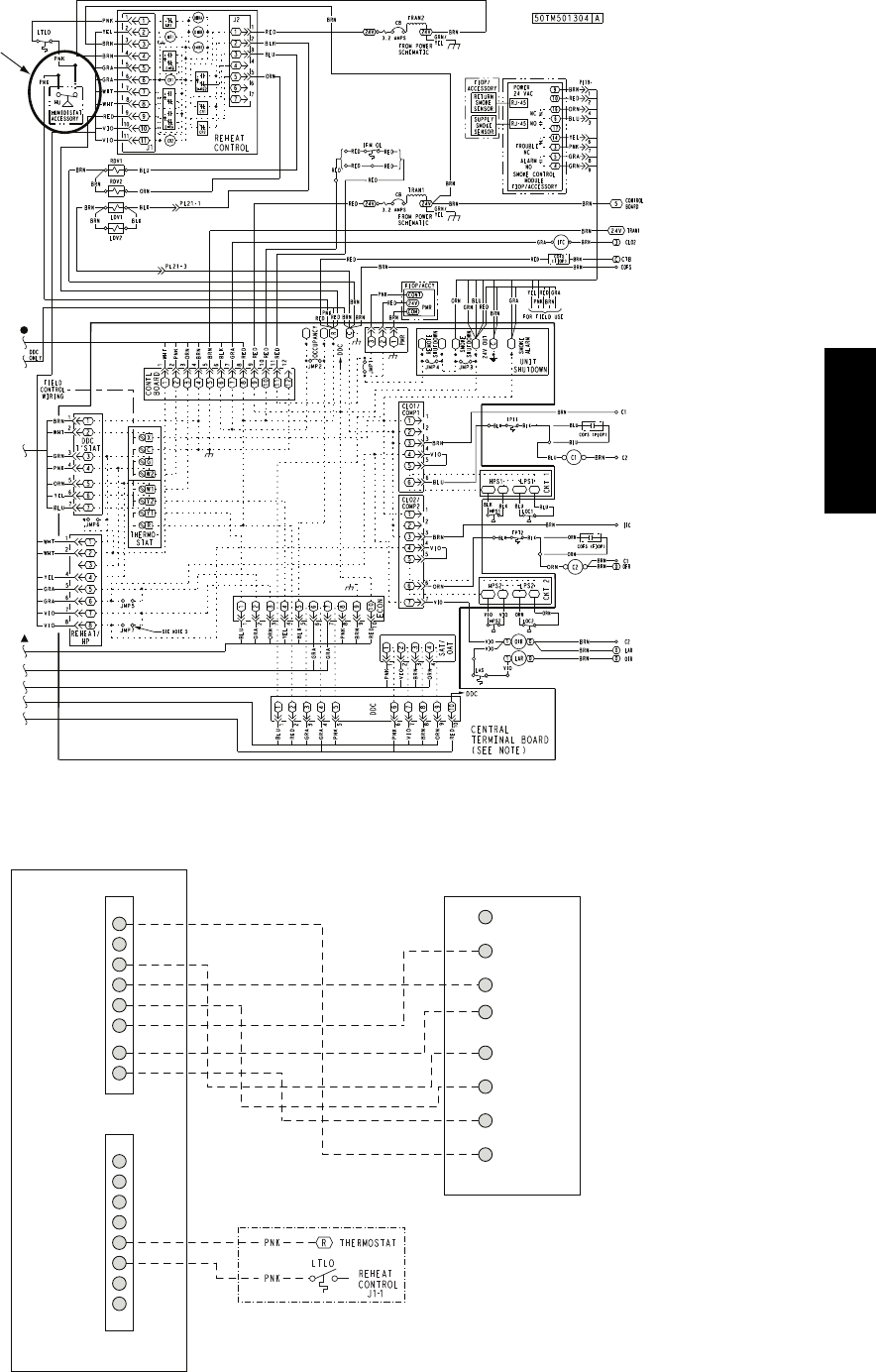
C11202
Fig. 46 -- PremierLink Wiring Schematic
48TC**16

24
C11203
Fig. 47 -- PremierLink Wiring Schematic with Humidi--MiZerR
48TC**16
25
Supply Air Temperature (SAT) Sensor —
On FIOP--equipped 48TC**16 units, the unit is supplied
with a supply--air temperature (SAT) sensor (33ZCSENSAT).
This sensor is a tubular probe type, approx 6--inches (12.7
mm) in length. It is a nominal 10--k ohm thermistor.
The SAT is factory--wired. The SAT probe is wire--tied to
the supply--air opening (on the horizontal opening end) in
its shipping position. Remove the sensor for installation.
Re--position the sensor in the flange of the supply--air
opening or in the supply air duct (as required by local
codes). Drill or punch a 1/2--in. hole in the flange or duct.
Use the template provided in the unit control box. Use two
field--supplied, self--drilling screws to secure the sensor
probe in a horizontal orientation. See Fig. 48.
SUPPLY AIR RETURN AIR
SUPPLY AIR
TEMPERATURE
SENSOR
ROOF
CURB
C10020
Fig. 48 -- Typical Mounting Location for Supply Air
Temperature (SAT) Sensor on Small Rooftop Units
NOTE: Refer to Form 33CS--67SI (or latest) for
complete PremierLink configuration, operating sequences
and troubleshooting information. Have a copy of this
manual available at unit set--up
NOTE: The sensor must be mounted in the discharge
airstream downstream of the cooling coil and any heating
devices. Be sure the probe tip does not come in contact
with any of the unit’s heater surfaces.
Outdoor Air Temperature (OAT) Sensor —
The OAT is factory--mounted in the EconoMi$er2 (FIOP or
accessory). It is a nominal 10k ohm thermistor attached to
an eyelet mounting ring.
EconoMi$er2 —
The PremierLink control is used with EconoMi$er2
(option or accessory) for outdoor air management. The
damper position is controlled directly by the PremierLink
control; EconoMi$er2 has no internal logic device.
Outdoor air management functions can be enhanced with
field--installation of these accessory control devices:
Enthalpy control (outdoor air or differential sensors)
Space CO2sensor
Outdoor air CO2sensor
Refer to Table 3 for accessory part numbers.
Field Connections
Field connections for accessory sensor and input devices
are made at the 16--pole terminal block (TB3) located
beneath the PremierLink control (see Fig. 46). Some input
devices also require a 24--vac signal source; connect at
CTB terminal R at “THERMOSTAT” connection strip for
this signal source. See connections figures on following
pages for field connection locations (and for continued
connections at the PremierLink board inputs). Route wires
to control box as indicated in Fig. 39.
Table 4 provides a summary of field connections for units
equipped with Space Sensor. Table 5 provides a summary of
field connections for units equipped with Space Thermostat.
Table 3 – PremierLink Sensor Usage
APPLICATION
OUTDOOR AIR
TEMPERATURE
SENSOR
RETURN AIR
TEMPERATURE
SENSOR
OUTDOOR AIR
ENTHALPY SENSOR
RETURN AIR
ENTHALPY SENSOR
Differential Dry Bulb
Temp e r a t u r e w it h
PremierLink
(PremierLink requires
4 --- 2 0 m A A c t u a t o r )
I n c l u d e d ---
CRTEMPSN001A00
R e q u i r e d ---
33ZCT55SPT
or equivalent
--- ---
Single Enthalpy with
PremierLink
(PremierLink requires
4 --- 2 0 m A A c t u a t o r )
I n c l u d e d ---
Not Used --- R e q u i r e s ---
33CSENTHSW ---
Differential Enthalpy
with PremierLink
(PremierLink requires
4 --- 2 0 m A A c t u a t o r )
I n c l u d e d ---
Not Used ---
R e q u i r e s ---
33CSENTHSW
or equivalent
R e q u i r e s ---
33CSENTSEN
or equivalent
NOTES:
CO2Sensors (Optional):
33ZCSENCO2 --- Room sensor (adjustable). Aspirator box is required for duct mounting of the sensor.
33ZCASPCO2 --- Aspirator box used for duct---mounted CO2room sensor.
33ZCT55CO2 --- Space temperature and CO2room sensor with override.
33ZCT56CO2 --- Space temperature and CO2room sensor with override and setpoint.
48TC**16

26
Table 4 – Space Sensor Mode
TB3 TERMINAL FIELD CONNECTION INPUT SIGNAL
1T 5 5 --- S E N / T 5 6 --- S E N Analog (10k thermistor)
2RMTOCC Discrete, 24VAC
3T 5 5 --- S E N / T 5 6 --- S E N Analog (10k thermistor)
4CMPSAFE Discrete, 24VAC
5T56---SET Analog (10k thermistor)
6FSD Discrete, 24VAC
7LOOP---PWR Analog, 24VDC
8SPS Discrete, 24VAC
9IAQ---SEN A n a l o g , 4 --- 2 0 m A
10 FILTER Discrete, 24VAC
11 I A Q --- C O M / O A Q --- C O M / R H --- C O M A n a lo g , 4 --- 2 0m A
12 CCN + (RED) Digital,,5VDC
13 OAQ ---SEN/RH ---SEN A n a l o g , 4 --- 2 0 m A
14 CCN Gnd (WHT) Digital, 5VDC
15 AUX OUT(Power Exhaust) (Output)Discrete 24VAC
16 CCN --- (BLK) Digital, 5VDC
LEGEND:
T 5 5 --- S p a c e Te m p e r a t u r e S e n s o r F S D --- F i r e S h u t d o w n
T 5 6 --- S p a c e Te m p e r a t u r e S e n s o r I A Q --- I n d o o r A i r Q u a l i t y ( C O 2)
CCN --- Carrier Comfort Network (communication bus) OAQ --- Outdoor Air Quality (CO2)
C M P S A F E --- C o m p r e s s o r S a f e t y R H --- R e l a t i v e H u m i d i t y
F I LT E R --- D i r t y F i l t e r S w i t c h S F S --- S u p p l y F a n S t a t u s
Table 5 – Thermostat Mode
TB3 TERMINAL FIELD CONNECTION INPUT SIGNAL
1RAT SEN Analog (10k thermistor)
2 G Discrete, 24VAC
3RAT SEN Analog (10k thermistor)
4Y1 Discrete, 24VAC
5
6Y2 Discrete, 24VAC
7LOOP---PWR Analog, 24VDC
8W1 Discrete, 24VAC
9I A Q --- S E N Analog, 4--- 20mA
10 W2 Discrete, 24VAC
11 I A Q --- C O M / O A Q --- C O M / R H --- C O M Analog, 4---20mA
12 CCN + (RED) Digital, 5VDC
13 O A Q --- S E N / R H --- S E N Analog, 4--- 20mA
14 CCN Gnd (WHT) Digital, 5VDC
15 AUX OUT (Power Exhaust) (Output) Discrete 24VAC
16 CCN --- (BLK) Digital, 5VDC
LEGEND:
CCN --- Carrier Comfort Network (communication bus) RH --- Relative Humidity
G --- Thermostat Fan W1 --- Thermostat Heat Stage 1
IAQ --- Indoor Air Quality (CO2) W2 --- Thermostat Heat Stage 2
OAQ --- Outdoor Air Quality (CO2) Y1 --- Thermostat Cool Stage 1
RAT --- Return Air Temperature Y2 --- Thermostat Cool Stage 2
48TC**16
27
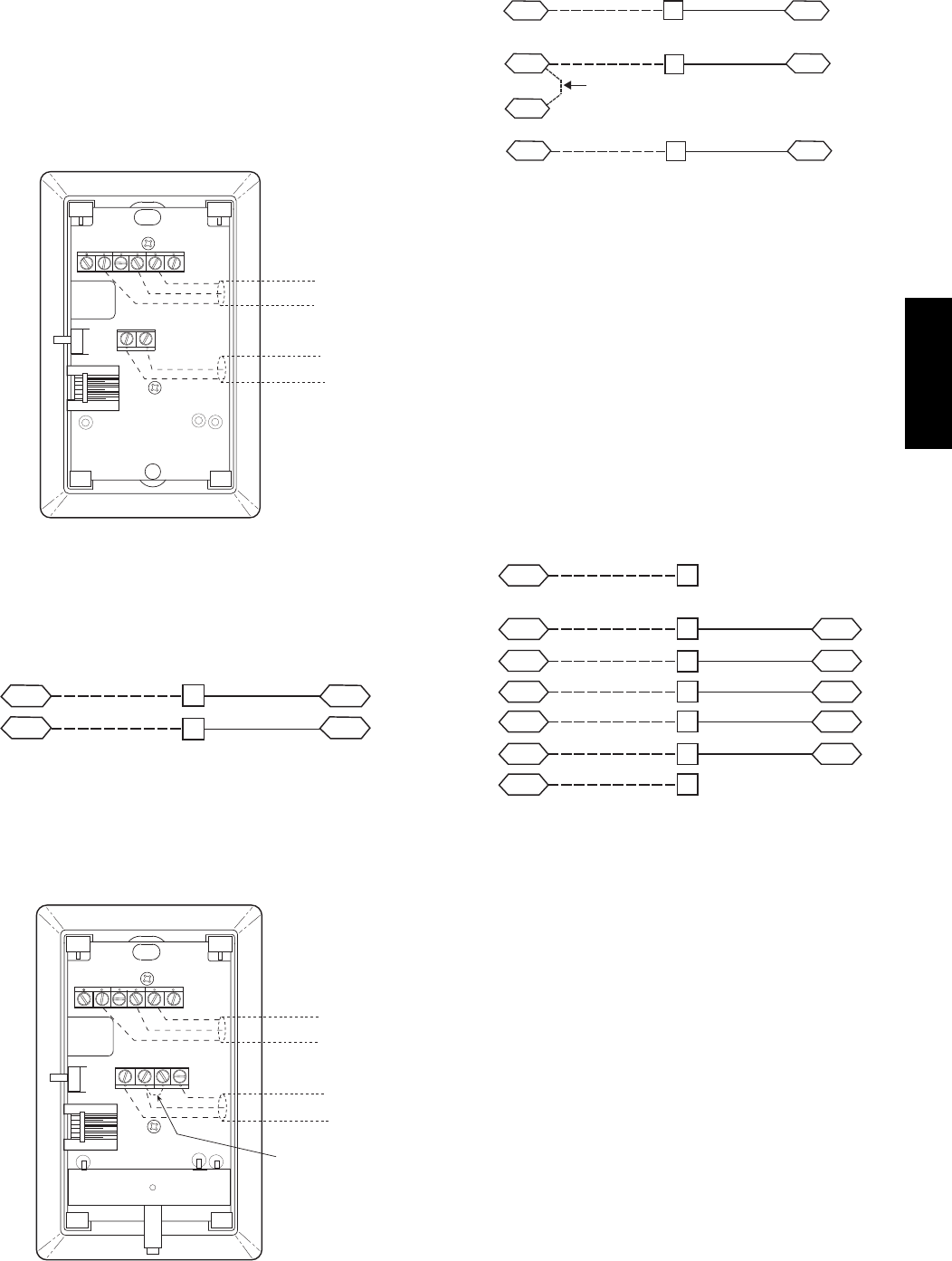
Space Sensors —
The PremierLink controller is factory--shipped configured
for Space Sensor Mode. A Carrier T--55 or T--56 space
sensor must be used. T--55 space temperature sensor
provides a signal of space temperature to the PremierLink
control. T--56 provides same space temperature signal plus
it allows for adjustment of space temperature setpoints
from the face of the sensor by the occupants.
2345 61
SW1
SEN
BRN (GND)
BLU (SPT)
RED(+)
WHT(GND)
BLK(-) CCN COM
SENSOR WIRING
C08201
Fig. 49 -- T--55 Space Temperature Sensor Wiring
Connect T--55: See Fig. 49 for typical T--55 internal
connections. Connect the T--55 SEN terminals to TB3
terminals 1 and 3 (see Fig. 50).
SEN J6-7
J6-6
1
3
TB3 PL
SEN
C10023
Fig. 50 -- PremierLink T--55 Sensor
Connect T--56: See Fig. 51 for T--56 internal connections.
Install a jumper between SEN and SET terminals as
illustrated. Connect T--56 terminals to TB3 terminals 1, 3
and 5 (see Fig. 52).
2345 61
SW1
SEN SET
Cool Warm
BRN (GND)
BLU (SPT)
RED(+)
WHT(GND)
BLK(-) CCN COM
SENSOR WIRING
JUMPER
TERMINALS
AS SHOWN
BLK
(T56)
C08202
Fig. 51 -- T--56 Internal Connections
SEN J6-7
J6-6
1
3
TB3 PL
SEN
SET
Jumper
TB3 PL
J6-5
5
SET
C10022
Fig. 52 -- PremierLink T--56 Sensor
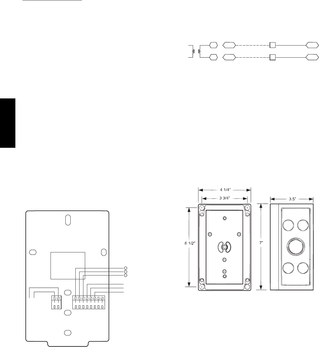
Connect Thermostat —
A 7--wire thermostat connection requires a 24--v power
source and a common connection. Use the R and C
terminals on the CTB’s THERMOSTAT connection strip
for these. Connect the thermostat’s Y1, Y2, W1, W2 and
G terminals to PremierLink TB3 as shown in Fig. 53.
If the 48TC**16 unit is equipped with factory--installed
smoke detector(s), disconnect the factory BLU lead at
TB3--6 (Y2) before connecting the thermostat. Identify the
BLU lead originating at CTB--DDC--1; disconnect at
TB3--6 and tape off. Confirm that the second BLU lead at
TB3--6 remains connected to PremierLink J4--8.
GJ4-12
J4-10
J4-8
Y1
Y2
2
RR
4
6
J4-6
J4-4
W2
C
8
10
C
SPACE
THERMOSTAT
CTB
THERMOSTAT
PL
W1
TB3
CTB
THERMOSTAT
C10283
Fig. 53 -- Space Thermostat Connections
If the 48TC**16 unit has an economizer system and
free--cooling operation is required, a sensor representing
Return Air Temperature must also be connected
(field--supplied and installed). This sensor may be a T--55
Space Sensor (see Fig. 49) installed in the space or in the
return duct, or it may be sensor PNO 33ZCSENSAT,
installed in the return duct. Connect this sensor to TB3--1
and TB3--3 per Fig. 50.
Configure the unit for Thermostat Mode —
Connect to the CCN bus using a CCN service tool and
navigate to PremierLink Configuration screen for Operating
Mode. Default setting is Sensor Mode (value 1). Change the
value to 0 to reconfigure the controller for Thermostat Mode.
When the PremierLink is configured for Thermostat
Mode, these functions are not available: Fire Shutdown
(FSD), Remote Occupied (RMTOCC), Compressor Safety
(CMPSAFE), Supply Fan Status (SFS), and Filter Pressure
Switch (FILTER).
48TC**16
28
Economizer Controls
Indoor Air Quality (CO2sensor) —
The indoor air quality sensor accessory monitors space
carbon dioxide (CO2) levels. This information is used to
monitor IAQ levels. Several types of sensors are available,
for wall mounting in the space or in return duct, with and
without LCD display, and in combination with space
temperature sensors. Sensors use infrared technology to
measure the levels of CO2present in the space air.
The CO2sensors are all factory set for a range of 0 to
2000 ppm and a linear mA output of 4 to 20. Refer to the
instructions supplied with the CO2sensor for electrical
requirements and terminal locations. See Fig. 54 for
typical CO2sensor wiring schematic.
To accurately monitor the quality of the air in the
conditioned air space, locate the sensor near a return--air
grille (if present) so it senses the concentration of CO2
leaving the space. The sensor should be mounted in a
location to avoid direct breath contact.
Do not mount the IAQ sensor in drafty areas such as near
supply ducts, open windows, fans, or over heat sources.
Allow at least 3 ft (0.9 m) between the sensor and any
corner. Avoid mounting the sensor where it is influenced
by the supply air; the sensor gives inaccurate readings if
the supply air is blown directly onto the sensor or if the
supply air does not have a chance to mix with the room air
before it is drawn into the return airstream.
87654321
21
HG
24 VAC
OR
24 VDC
NC ALARM
RELAY
CONTACTS
COM
NO
}
0-10VDC
SIG COM
4-20mA
+
+
-
+-
J3 J4
C08635
Fig. 54 -- Indoor/Outdoor Air Quality (CO2)Sensor
(33ZCSENCO2) -- Typical Wiring Diagram
Wiring the Indoor Air Quality Sensor: For each sensor,
use two 2--conductor 18 AWG (American Wire Gage)
twisted--pair cables (unshielded) to connect the separate
isolated 24 vac power source to the sensor and to connect
the sensor to the control board terminals.
To connect the sensor to the control, identify the positive
(4 to 20 mA) and ground (SIG COM) terminals on the
sensor. See Fig. 54. Connect the 4--20 mA terminal to
terminal TB3--9 and connect the SIG COM terminal to
terminal TB3--11. See Fig. 55.
SEN J5-5
J5-3
COM
9
11
TB3
TB3
IAQ Sensor
PL
24 VAC
C10284
Fig. 55 -- Indoor CO2Sensor (33ZCSENCO2)
Connections
Refer to Form 33CS--67SI, PremierLink Installation,
Start--up, and Configuration Instructions, for detailed
configuration information
Outdoor Air Quality Sensor
(PNO 33ZCSENCO2 plus weatherproof enclosure) —
The outdoor air CO2sensor is designed to monitor carbon
dioxide (CO2) levels in the outside ventilation air and
interface with the ventilation damper in an HVAC system.
The OAQ sensor is packaged with an outdoor cover. See
Fig. 56. The outdoor air CO2sensor must be located in the
economizer outside air hood.
COVER REMOVED SIDE VIEW
C07135
Fig. 56 -- Outdoor Air Quality Sensor Cover
Wiring the Outdoor Air CO2Sensor: A dedicated
power supply is required for this sensor. A two--wire cable
is required to wire the dedicated power supply for the
sensor. The two wires should be connected to the power
supply and terminals 1 and 2.
To connect the sensor to the control, identify the positive
(4 to 20 mA) and ground (SIG COM) terminals on the
OAQ sensor. See Fig. 54. Connect the 4 to 20 mA
terminal to the TB3--13 terminal of the 48TC**16.
Connect the SIG COM terminal to the TB3--11 terminal of
the 48TC**16. See Fig. 57.
48TC**16
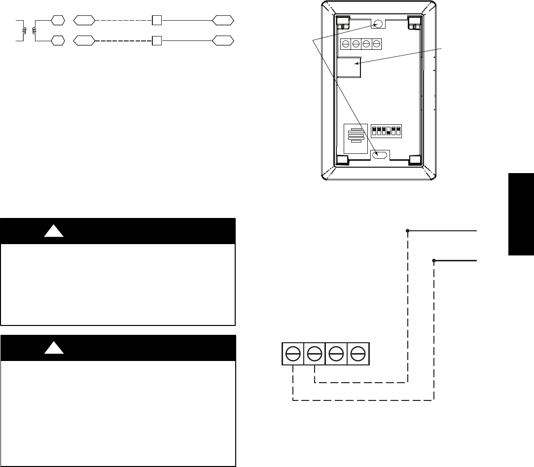
29
SEN J5-2
J5-3
COM
13
11
TB3
TB3
IAQ Sensor
PL
24 VAC
C10285
Fig. 57 -- Outdoor CO2Sensor Connections
Space Relative Humidity Sensor or Humidistat
Connections —
Space Relative Humidity Sensor connections: The
accessory space relative humidity sensor (33ZCSENSRH-01)
is installed on an interior wall to measure the relative
humidity of the air within the occupied space.
The use of a standard 2 X 4 inch electrical box to
accommodate the wiring is recommended for installation.
The sensor can be mounted directly on the wall, if
acceptable by local codes.
UNIT DAMAGE HAZARD
Failure to follow this caution may result in
permanent damage to the sensor.
DO NOT clean or touch the sensing element with
chemical solvents as they can permanently damage the
sensor.
CAUTION
!
UNIT PERFORMANCE HAZARD
Failure to follow this caution will result in inaccurate
sensor readings.
DO NOT mount the sensor in drafty areas such as near
heating or air--conditioning ducts, open windows, fans,
or over heat sources such as baseboard heaters,
radiators, or wall--mounted dimmers. Sensors mounted
in those areas will produce inaccurate readings.
CAUTION
!
If the sensor is installed directly on a wall service, install the
humidity sensor using 2 screws and 2 hollow wall anchors
(field supplied). Do not over tighten screws. See Fig. 58.
The sensor must be mounted vertically on the wall. The
Carrier logo should be orientated correctly when the
sensor is properly mounted.
Avoid corner locations. Allow at least 4 ft between the
sensor and any corner. Airflow near corners tends to be
reduced, resulting in erratic sensor readings. The sensor
should be vertically mounted approximately 5 ft up from
the floor, beside the space temperature sensor.
For wiring distances up to 500 feet, use a 3--conductor, 18
or 20 AWG cable. ACCN communication cable can be
used, although the shield is not required. The shield must
be removed from the sensor end of the cable if this cable
is used. See Fig. 59 for wiring details.
SW2
12345 6
ON
Io Vin Gnd Vo
MOUNTING
HOLES
WIRING
OPENING
C11084
Fig. 58 -- Space Relative Humidity Sensor Installation
Io VoVin Gnd
BLACK
RED
TB3-7
TB3-13
C11085
Fig. 59 -- Space Relative Humidity Sensor Connection
The power for the sensor is provided by the PremierLink
control on terminal J5--4 (+33 to +35vdc).
To wire the sensor:
1. At the sensor, remove 4 inches of the jacket from the
cable. Strip 1/4inch of insulation from each conduct-
or. Route the cable through the wire clearance open-
ing in the center of the sensor. See Fig. 58.
2. Connect a field--supplied BLACK wire to the sensor
screw terminal marked Vin.
3. Connect a field--supplied RED wire into the sensor
screw terminal marked Io.
4. Connect the field--supplied RED wire from the sensor
to TB3--13.
5. Connect the field--supplied BLACK wire from the
sensor to TB3--7.
Humidistat connections: A humidistat can not be directly
connected to the PremierLink controller. Follow the
instructions on pages 20 & 21 to connect a humidistat or a
thermostat as an electromechanical device.
48TC**16
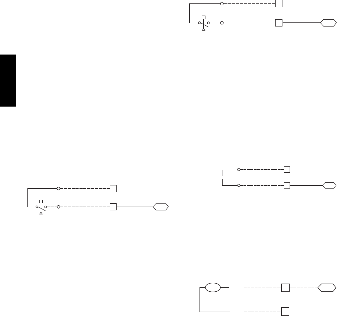
30
Smoke Detector/Fire Shutdown (FSD) —
This function is available only when PremierLink is
configured for (Space) Sensor Mode. The unit is
factory--wired for PremierLink FSD operation when
PremierLink is factory--installed.
On 48TC**16 units equipped with factory--installed
Smoke Detector(s), the smoke detector controller
implements the unit shutdown through its NC contact set
connected to the unit’s CTB input. The FSD function is
initiated via the smoke detector’s Alarm NO contact set.
The PremierLink communicates the smoke detector’s
tripped status to the CCN building control. See Fig. 46,
the PremierLink wiring schematic.
Filter Status Switch —
This function is available only when PremierLink is
configured for (Space) Sensor Mode.
PremierLink control can monitor return filter status in two
ways: By monitoring a field--supplied/installed filter
pressure switch or via supply fan runtime hours.
Using switch input: Install the dirty filter pressure switch
according to switch manufacturer’s instructions, to
measure pressure drop across the unit’s return filters.
Connect one side of the switch’s NO contact set to CTB’s
THERMOSTAT--R terminal. Connect the other side of the
NO contact set to TB3--10. Setpoint for Dirty Filter is set
at the switch. See Fig. 60.
R
TB3
J4-4
PL
Filter Switch (NO, close on rising pressure (high drop))
CTB
Thermostat
10
C10286
Fig. 60 -- PremierLink Filter Switch Connection
When the filter switch’s NO contact set closes as filter
pressure drop increases (indicating dirt--laden filters), the
input signal to PremierLink causes the filter status point to
read “DIRTY”.
Using Filter Timer Hours: Refer to Form 33CS--67SI for
instructions on using the PremierLink Configuration
screens and on unit alarm sequence.
Supply Fan Status Switch —
The PremierLink control can monitor supply fan operation
through a field--supplied/installed differential pressure
switch. This sequence will prevent (or interrupt) operation
of unit cooling, heating and economizer functions until
the pressure switch contacts are closed indicating proper
supply fan operation.
Install the differential pressure switch in the supply fan
section according to switch manufacturer’s instructions.
Arrange the switch contact to be open on no flow and to
close as pressure rises indicating fan operation.
Connect one side of the switch’s NO contact set to CTB’s
THERMOSTAT--R terminal. Connect the other side of the
NO contact set to TB3--8. Setpoint for Supply Fan Status
is set at the switch. See Fig. 61.
R
TB3
J4-6
PL
Fan (Pressure) Switch (NO, close on rise in pressure)
CTB
Thermostat
8
C10287
Fig. 61 -- PremierLink Wiring Fan Pressure Switch
Connection
Remote Occupied Switch —
The PremierLink control permits a remote timeclock to
override the control’s on--board occupancy schedule and
place the unit into Occupied mode. This function may also
provide a “Door Switch” time delay function that will
terminate cooling and heating functions after a 2--20 minute
delay.
Connect one side of the NO contact set on the timeclock
to CTB’s THERMOSTAT--R terminal. Connect the other
side of the timeclock contact to the unit’s TB3--2 terminal.
See Fig. 62.
R
2
TB3 PL
Time Clock
Remote Occupied LCTB
Thermostat
J4-12
C10288
Fig. 62 -- PremierLink Wiring Remote Occupied
Refer to Form 33CS--67SI for additional information on
configuring the PremierLink control for Door Switch
timer function.
Power Exhaust (output) —
Connect the accessory Power Exhaust contactor coils(s)
per Fig. 63.
J8-3
15
C
TB3 PL
PEC
TAN
Power Exhaust
CTB
THERMOSTAT
GRA
C10289
Fig. 63 -- PremierLink Power Exhaust Output
Connection
48TC**16
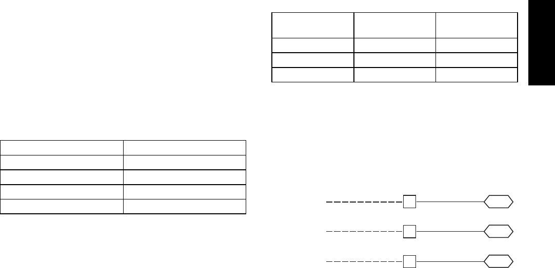
31
CCN Communication Bus —
The PremierLink controller connects to the bus in a daisy
chain arrangement. Negative pins on each component
must be connected to respective negative pins, and
likewise, positive pins on each component must be
connected to respective positive pins. The controller
signal pins must be wired to the signal ground pins.
Wiring connections for CCN must be made at the 3--pin
plug.
At any baud (9600, 19200, 38400 baud), the number of
controllers is limited to 239 devices maximum. Bus length
may not exceed 4000 ft, with no more than 60 total
devices on any 1000--ft section. Optically isolated RS--485
repeaters are required every 1000 ft.
NOTE: Carrier device default is 9600 band.
Communications Bus Wire Specifications: The CCN
Communication Bus wiring is field--supplied and
field--installed. It consists of shielded 3--conductor cable
with drain (ground) wire. The cable selected must be
identical to the CCN Communication Bus wire used for
the entire network.
See Table 6 for recommended cable.
Table 6 – Recommended Cables
MANUFACTURER CABLE PART NO.
Alpha 2413 or 5463
American A22503
Belden 8772
Columbia 02525
NOTE: Conductors and drain wire must be at least 20
AWG, stranded, and tinned copper. Individual conductors
must be insulated with PVC, PVC/nylon, vinyl, Teflon, or
polyethylene. An aluminum/polyester 100% foil shield
and an outer jacket of PVC, PVC/nylon, chrome vinyl, or
Teflon with a minimum operating temperature range of
-- 2 0 _Cto60_C is required. Do not run communication
wire in the same conduit as or next to any AC voltage
wiring.
The communication bus shields must be tied together at
each system element. If the communication bus is entirely
within one building, the resulting continuous shield must
be connected to ground at only one single point. If the
communication bus cable exits from one building and
enters another building, the shields must be connected to
the grounds at a lightning suppressor in each building (one
point only).
Connecting CCN Bus:
NOTE: When connecting the communication bus cable,
a color code system for the entire network is
recommended to simplify installation and checkout. See
Table 7 for the recommended color code.
Table 7 – Color Code Recommendations
SIGNAL TYPE CCN BUS WIRE
COLOR
CCN PLUG PIN
NUMBER
+Red 1
Ground White 2
--- Black 3
Connect the CCN (+) lead (typically RED) to the unit’s
TB3--12 terminal. Connect the CCN (ground) lead
(typically WHT) to the unit’s TB3--14 terminal. Connect
the CCN (--) lead (typically BLK) to the unit’s TB3--16
terminal. See Fig. 64.
CCN Bus
J2-1
J2-2GND (WHT)
12
14
TB3
J2-3– (BLK) 16
TB3
TB3 PL
+ (RED)
C10290
Fig. 64 -- PremierLink CCN Bus Connections
48TC**16
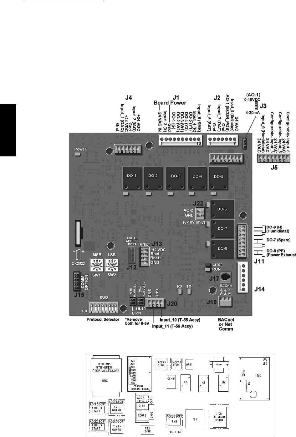
32
RTU Open Control System
The RTU Open control is factory--mounted in the
48TC**16 unit’s main control box, to the left of the CTB.
See Fig. 66. Factory wiring is completed through
harnesses connected to the CTB. Field connections for
RTU Open sensors will be made at the Phoenix connectors
on the RTU Open board. The factory--installed RTU Open
control includes the supply--air temperature (SAT) sensor.
The outdoor air temperature (OAT) sensor is included in
the FIOP/accessory EconoMi$er2 package.
The RTU Open controller is an integrated component of
the Carrier rooftop unit. Its internal application
programming provides optimum performance and energy
efficiency. RTU Open enables the unit to run in 100%
stand--alone control mode, Carrier’s I--Vu Open network,
or a Third Party Building Automation System (BAS).
On--board DIP switches allow you to select your protocol
(and baud rate) of choice among the four most popular
protocols in use today: BACnet, Modbus, Johnson N2 and
LonWorks. (See Fig. 65.)
Refer to Table 8, RTU Open Controller Inputs and Outputs
for locations of all connections to the RTU Open board.
C10811
Fig. 65 -- RTU Open Multi--Protocol Control Board
C10810
Fig. 66 -- 48TC**16 Control Box Component Locations
48TC**16
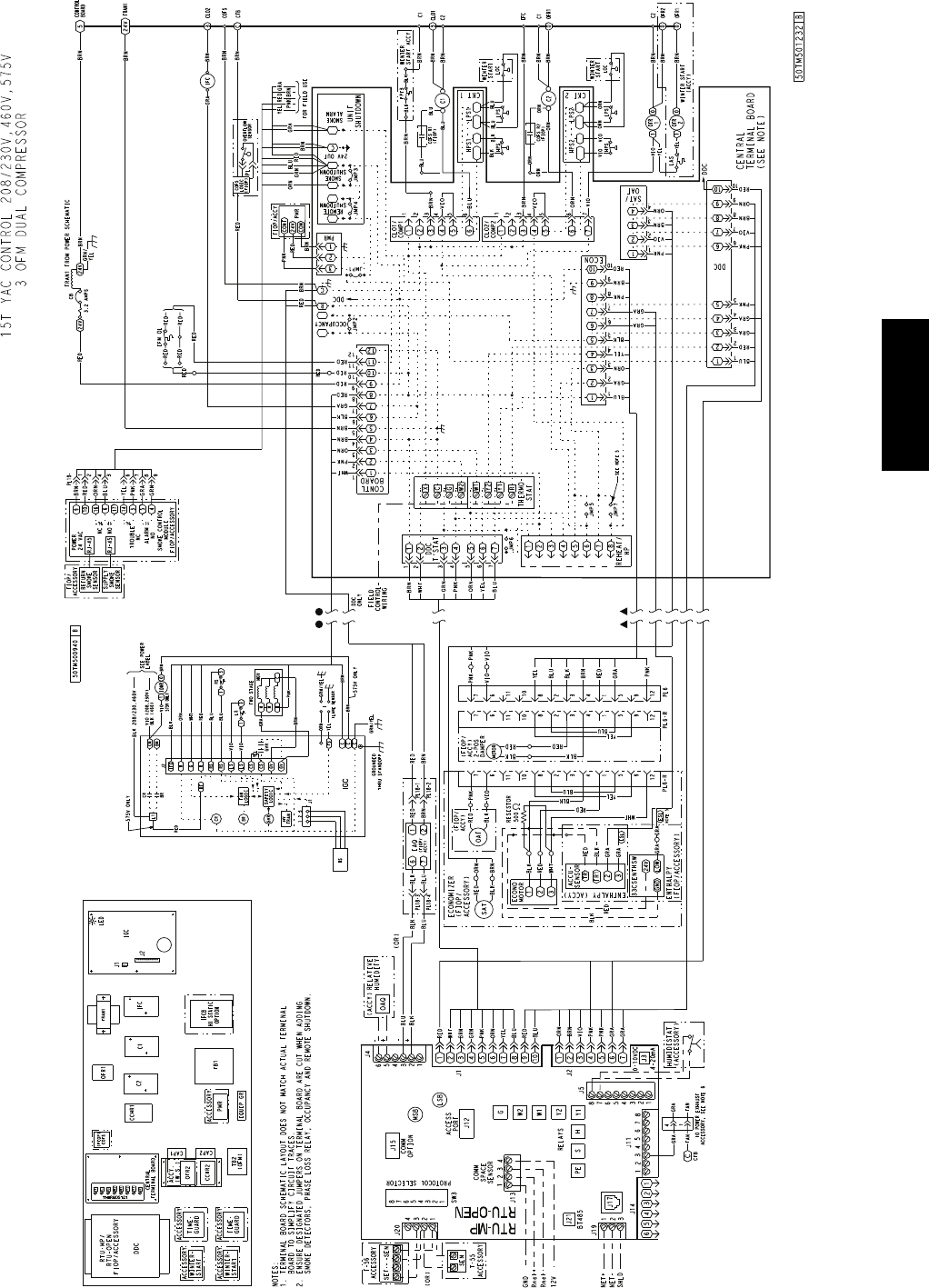
33
C11204
Fig. 67 -- RTU Open System Control Wiring Diagram
48TC**16
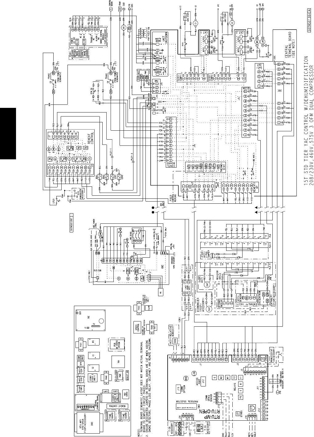
34
C11205
Fig. 68 -- RTU Open System Control Wiring Diagram with Humidi--MiZerR
48TC**16

35
Table 8 – RTU Open Controller Inputs and Outputs
POINT NAME BACnet OBJECT
NAME TYPE OF I/O CONNECTION PIN
NUMBER(S)
DEDICATED INPUTS
Space Temp / Zone Temp zone_temp AI (10K Thermistor) J 2 0 --- 1 , 2
Supply Air Temperature sa_temp AI (10K Thermistor) J 2 --- 1 , 2
Outdoor Air Temperature oa_temp AI (10K Thermistor) J 2 --- 3 , 4
Space Temperature Offset Pot stpt_adj_offset AI (100K Potentiometer) J 2 0 --- 3
Safety Chain Feedback safety_status DI (24 VAC) J 1 --- 9
Compressor Safety Status comp_status DI (24 VAC) J 1 --- 2
Fire Shutdown Status firedown_status DI (24 VAC) J 1 --- 1 0
Enthalpy Status enthalpy_status DI (24 VAC) J 2 --- 6
Humidistat Input Status humstat_status DI (24 VAC) J 5 --- 7
CONFIGURABLE INPUTS
Indoor Air CO2 iaq A I ( 4 --- 2 0 m a )
J 4 --- 2 o r J 4 --- 5Outdoor Air CO2 oaq A I ( 4 --- 2 0 m a )
Space Relative Humidity space_rh A I ( 4 --- 2 0 m a )
Supply Fan Status* sfan_status DI (24 VAC)
J 5 --- 1 o r J 5 --- 3 o r
J55orJ5---7
Filter Status* filter_status DI (24 VAC)
Door Contact Input* door_contact_status DI (24 VAC)
Occupancy Contact* occ_contact_status DI (24 VAC)
OUTPUTS
Economizer Output econ_output A O ( 4 --- 2 0 m a ) J 2 --- 5
SupplyFanRelayState sfan DO Relay (24VAC , 1A) J 1 --- 4
Compressor 1 Relay State comp_1 DO Relay (24VAC , 1A) J 1 --- 8
Compressor 2 Relay State comp_2 DO Relay (24VAC , 1A) J 1 --- 7
Heat Stage 1 Relay State heat_1 DO Relay (24VAC , 1A) J 1 --- 6
Heat Stage 2 Relay State heat_2 DO Relay (24VAC , 1A) J 1 --- 5
Power Exhaust Relay State pexh DO Relay (24VAC , 1A) J 1 1 --- 3
Dehumidification Relay State dehum DO Relay (24VAC, 1A) J 1 1 --- 7 , 8
LEGEND
AI --- A n a l o g I n pu t
AO --- A n a l o g O u tp u t
DI --- D i sc r e te In p u t
DO --- Discrete Output
* These inputs (if installed) take the place of the default input on the specific channel according to schematic.
Pa r a l l e l p i n s J 5 --- 1 = J 2 --- 6 , J 5 --- 3 = J 1 --- 1 0 , J 5 --- 5 = J 1 --- 2 a re u s e d f or f i e l d --- i n st a l l a ti o n .
The RTU Open controller requires the use of a Carrier
space sensor. A standard thermostat cannot be used with
the RTU Open system.
Supply Air Temperature (SAT) Sensor —
On FIOP--equipped 48TC**16 unit, the unit is supplied with
a supply--air temperature (SAT) sensor (33ZCSENSAT). This
sensor is a tubular probe type, approx 6--inches (12.7 mm) in
length. It is a nominal 10--k ohm thermistor.
The SAT is factory--wired. The SAT probe is wire--tied to
the supply--air opening (on the horizontal opening end) in
its shipping position. Remove the sensor for installation.
Re--position the sensor in the flange of the supply--air
opening or in the supply air duct (as required by local
codes). Drill or punch a 1/2--in. hole in the flange or duct.
Use two field--supplied, self--drilling screws to secure the
sensor probe in a horizontal orientation. See Fig. 48.
Outdoor Air Temperature (OAT) Sensor —
The OAT is factory--mounted in the EconoMi$er2 (FIOP
or accessory). It is a nominal 10k ohm thermistor attached
to an eyelet mounting ring.
EconoMi$er2 —
The RTU Open control is used with EconoMi$er2 (option
or accessory) for outdoor air management. The damper
position is controlled directly by the RTU Open control;
EconoMi$er2 has no internal logic device.
Outdoor air management functions can be enhanced with
field--installation of these accessory control devices:
Enthalpy control (outdoor air or differential sensors)
Space CO2sensor
Outdoor air CO2sensor
Field Connections
Field connections for accessory sensors and input devices
are made the RTU Open, at plugs J1, J2, J4, J5, J11 and
J20. All field control wiring that connects to the RTU
Open must be routed as shown in Fig. 39. This routing
provides the UL required clearance between high-- and
low--voltage wiring. Connect to the wires to the
removable Phoenix connectors and then reconnect the
connectors to the board.
48TC**16

36
Space Temperature (SPT) Sensors —
There are two types of SPT sensors available from Carrier,
resistive input non-communicating (T55, T56, and T59)
and Rnet communicating (SPS, SPPL, SPP, and SPPF)
sensors. Each type has a variety of options consisting of:
timed override button, set point adjustment, a LCD
screen, and communication tie in. Space temperature can
be also be written to from a building network or zoning
system. However, it is still recommended that return air
duct sensor be installed to allow stand-alone operation for
back-up. Refer to the configuration section for details on
controller configurations associated with space sensors.
Field connections to T--55, T--56 and T--59 are provided as
examples.
S33ZCT55SPT, space temperature sensor with override
button (T--55)
S33ZCT56SPT, space temperature sensor with override
button and setpoint adjustment (T--56)
S33ZCT59SPT, space temperature sensor with LCD
(liquid crystal display) screen, override button, and
setpoint adjustment (T--59)
Use 20 gauge wire to connect the sensor to the controller.
The wire is suitable for distances of up to 500 ft. Use a
three--conductor shielded cable for the sensor and setpoint
adjustment connections. If the setpoint adjustment
(slidebar) is not required, then an unshielded, 18 or 20
gauge, two--conductor, twisted pair cable may be used.
Connect T--55: See Fig. 49 for typical T--55 internal
connections. Connect the T--55 SEN terminals to RTU Open
J20--1 and J20--2. See Fig. 69.
SEN
SEN
J20-1
J20-2
C08460
Fig. 69 -- RTU Open T--55 Sensor Connections
Connect T--56: See Fig. 51 for T--56 internal connections.
Install a jumper between SEN and SET terminals as
illustrated. Connect T--56 terminals to RTU Open J20--1,
J20--2 and J20--3 per Fig. 70.
SEN J20-1
J20-2
SEN
SET
Jumper
J20-3
SET
C08461
Fig. 70 -- RTU Open T--56 Sensor Connections
Connect T--59: The T--59 space sensor requires a
separate, isolated power supply of 24 VAC. See Fig. 71
for internal connections at the T--59. Connect the SEN
terminal (BLU) to RTU Open J20--1. Connect the COM
terminal (BRN) to J20--2. Connect the SET terminal (STO
or BLK) to J20--3.
OR SET SEN
OPB COM- PWR+
BLU (SPT)
BLK (STO)
24 VAC
SENSOR
WIRING
POWER
WIRING
BRN (COM)
NOTE: Must use a separate isolated transformer.
J20-3
J20-2
J20-1
C10291
Fig. 71 -- Space Temperature Sensor Typical Wiring
(33ZCT59SPT)
Indoor Air Quality (CO2sensor) —
The indoor air quality sensor accessory monitors space
carbon dioxide (CO2) levels. This information is used to
monitor IAQ levels. Several types of sensors are available,
for wall mounting in the space or in return duct, with and
without LCD display, and in combination with space
temperature sensors. Sensors use infrared technology to
measure the levels of CO2present in the space air.
The CO2sensors are all factory set for a range of 0 to
2000 ppm and a linear mA output of 4 to 20. Refer to the
instructions supplied with the CO2sensor for electrical
requirements and terminal locations. See Fig. 54 for
typical CO2sensor wiring schematic.
To accurately monitor the quality of the air in the
conditioned air space, locate the sensor near a return--air
grille (if present) so it senses the concentration of CO2
leaving the space. The sensor should be mounted in a
location to avoid direct breath contact.
Do not mount the IAQ sensor in drafty areas such as near
supply ducts, open windows, fans, or over heat sources.
Allow at least 3 ft (0.9 m) between the sensor and any
corner. Avoid mounting the sensor where it is influenced
by the supply air; the sensor gives inaccurate readings if
the supply air is blown directly onto the sensor or if the
supply air does not have a chance to mix with the room air
before it is drawn into the return airstream.
48TC**16
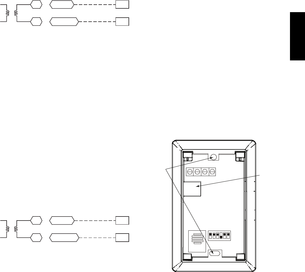
37
Wiring the Indoor Air Quality Sensor: For each sensor,
use two 2--conductor 18 AWG (American Wire Gage)
twisted--pair cables (unshielded) to connect the separate
isolated 24 vac power source to the sensor and to connect
the sensor to the control board terminals.
To connect the sensor to the control, identify the positive
(4 to 20 mA) and ground (SIG COM) terminals on the
sensor. See Fig. 54. Connect the 4--20 mA terminal to
RTU Open J4--2 and connect the SIG COM terminal to
RTU Open J4--3. See Fig. 72.
4-20mA
SIG COM
J4-2
J4-3
IAQ Sensor
24 VAC
C10738
Fig. 72 -- RTU Open / Indoor CO2Sensor
(33ZCSENCO2) Connections
Outdoor Air Quality Sensor
(PNO 33ZCSENCO2 plus weatherproof enclosure) —
The outdoor air CO2sensor is designed to monitor carbon
dioxide (CO2) levels in the outside ventilation air and
interface with the ventilation damper in an HVAC system.
The OAQ sensor is packaged with an outdoor cover. See
Fig. 56. The outdoor air CO2sensor must be located in the
economizer outside air hood.
Wiring the Outdoor Air CO2Sensor: A dedicated
power supply is required for this sensor. A two--wire cable
is required to wire the dedicated power supply for the
sensor. The two wires should be connected to the power
supply and terminals 1 and 2.
To connect the sensor to the control, identify the positive
(4 to 20 mA) and ground (SIG COM) terminals on the
OAQ sensor. See Fig. 54. Connect the 4 to 20 mA
terminal to RTU Open J4--5. Connect the SIG COM
terminal to RTU Open J4--6. See Fig. 73.
4-20mA
SIG COM
J4-5
J4-6
OAQ Sensor/RH Sensor
24 VAC
C10739
Fig. 73 -- RTU Open / Outdoor CO2Sensor
(33ZCSENCO2) Connections
Space Relative Humidity Sensor or Humidistat —
Humidi--MiZerRControl Wiring: In units equipped
with the Humidi--MiZer option there are two pink (PNK)
wires loose in the control box used to control the
dehumidification function of the unit. These pink wires
are meant to be tied to a space humidistat or thermidistat
on an electromechanical unit. On RTU Open equipped
units these pink wires must be connected to J11--7 & 8 to
allow the Open board to operate the dehumidification
function for the unit. Disconnect the J11 Phoenix style
connector from the board and use the plug screws to
secure the pink wires in pins 7 and 8, reconnect the plug
to the board at J11.
Relative Humidity Sensors (Space or Duct Mounted):
The accessory space humidity sensor (33ZCSENSRH-01)
or duct humidity sensor (33ZCSENDRH-01) is used to
measure the relative humidity of air within the space or
return air duct. The RH reading is used to control the
Humidi--MiZer option of the rooftop unit. For wiring
distances up to 500 ft (152 m), use a 3--conductor, 18 or
20 AWG shielded cable. The shield must be removed
from the sensor end of the cable and grounded at the unit
end. The current loop power for sensor is provided by the
RTU Open controller as 24vdc. Refer to the instructions
supplied with the RH sensor for the electrical
requirements and terminal locations. RTU Open
configurations must be changed after adding an RH
sensor. See Fig. 74 and 75 for typical RH sensor wiring.
SJ4--1 or J4--4 = 24vdc loop power
SJ4--2 or J4--5 = 4--20mA signal input
NOTE: The factory default for dehumidification control
is normally open humidistat.
SW2
12345 6
ON
Io Vin Gnd Vo
MOUNTING
HOLES
WIRING
OPENING
Vin - J4-1 or J4-4 24Vdc
Io - J4-2 or J4-5 -20mA output
C11087
Fig. 74 -- Space Relative Humidity Sensor Typical Wiring
48TC**16
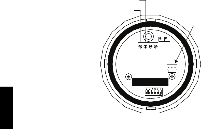
38
Relative Humidity Sensor
(Polarized Male Connector)
J4-1 or J4-4 + 24 VDC Supply Voltage
J4-2 or J4-5 (-) 4 to 20 mA Current Loop Output
to RTU-OPEN
4-20 VAC GND 0-5V
mA or or
VDC 0-10V
SPAN
ZERO
C10839
Fig. 75 -- Duct Relative Humidity Sensor Typical Wiring
Humidistat: The accessory humidistat provides the RTU
Open insight to the relative humidity in the space. The
humidistat reads the RH level in the space and compares it
to its setpoint to operate a dry contact. The humidistat is a
dedicated input on the configurable input 9 and tells the
RTU Open when the RH level is HIGH or LOW. The
normal condition for humidity is LOW. A normally open
humidistat is the factory default control for the
Humidi--MiZerRoption.
To wire in the field:
SJ5--8 = 24 VAC source for dry contact
SJ5--7 = Signal input
Smoke Detector/Fire Shutdown (FSD) —
On 48TC**16 units equipped with factory--installed
Smoke Detector(s), the smoke detector controller
implements the unit shutdown through its NC contact set
connected to the unit’s CTB input. The FSD function is
initiated via the smoke detector’s Alarm NO contact set.
The RTU Open controller communicates the smoke
detector’s tripped status to the BAS building control. See
Fig. 67, the RTU Open System Control Wiring Diagram.
The Fire Shutdown Switch configuration,
MENU
→
Config
→
Inputs
→
input 5, identifies the normally
open status of this input when there is no fire alarm.
Connecting Discrete Inputs —
Filter Status: The filter status accessory is a field--installed
accessory. This accessory detects plugged filters. When
installing this accessory, the unit must be configured for
filter status by setting MENU
→
Config
→
Inputs
→
input 3, 5,
8, or 9 to Filter Status and normally open (N/O) or normally
closed (N/C). Input 8 or 9 is recommended for easy of
installation. Refer to Fig. 65 and Fig. 67 or Fig. 68 for wire
terminations at J5.
Fan Status: The fan status accessory is a field--installed
accessory. This accessory detects when the indoor fan is
blowing air. When installing this accessory, the unit must
be configured for fan status by setting
MENU
→
Config
→
Inputs
→
input3,5,8,or9to Fan
Status and normally open (N/O) or normally closed (N/C).
Input 8 or 9 is recommended for easy of installation. Refer
to Fig. 65 and Fig. 67 or Fig. 68 for wire terminations at
J5.
Remote Occupancy: The remote occupancy accessory is
a field--installed accessory. This accessory overrides the
unoccupied mode and puts the unit in occupied mode.
When installing this accessory, the unit must be
configured for remote occupancy by setting
MENU
→
Config
→
Inputs
→
input3,5,8,or9to Remote
Occupancy and normally open (N/O) or normally closed
(N/C).
Also set MENU
→
Schedules
→
occupancy source to DI
on/off. Input 8 or 9 is recommended for easy of
installation. Refer to Fig. 65 and Table 8 for wire
terminations at J5.
Power Exhaust (output): The relay used by the RTU
Open board to control power exhaust is a dry contact
which means it does not have 24vac. This 24vac must be
connected to the relay to allow it to operate the power
exhaust relay in the PE accessory. A 24vac source must be
provided to J11--2 on the RTU Open control board. This
can be provided by the unit’s transformer from various
sources. The “R” terminal on the unit’s low voltage
terminal board (LVTB) is a logical source. Refer to Fig.
65 and Fig. 67 or Fig. 68 for wire terminations at J11.
48TC**16
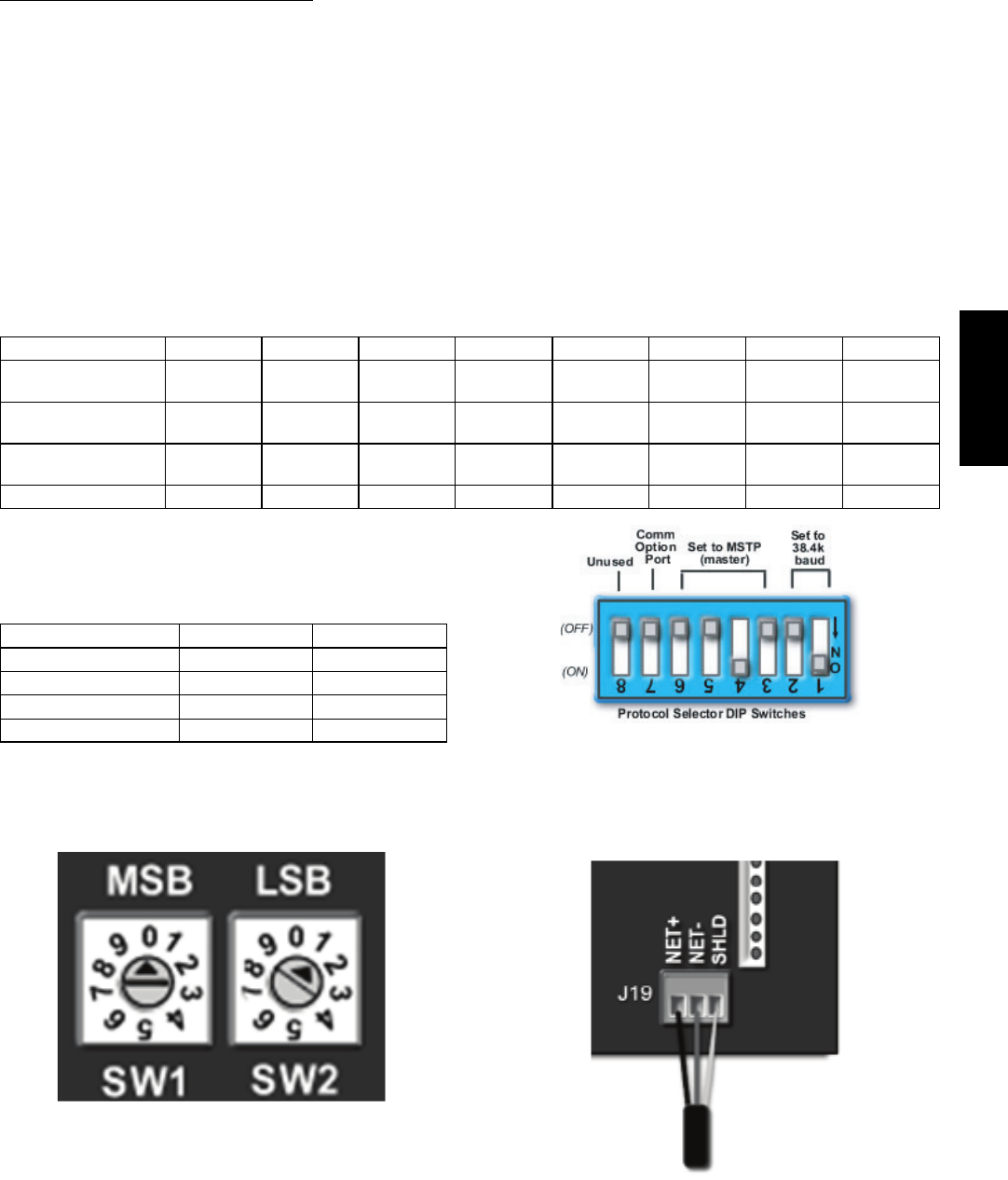
39
Communication Wiring -- Protocols
General —
Protocols are the communication languages spoken by
control devices. The main purpose of a protocol is to
communicate information in the most efficient method
possible. Different protocols exist to provide different
kinds of information for different applications. In the BAS
application, many different protocols are used, depending
on manufacturer. Protocols do not change the function of
a controller; just make the front end user different.
The RTU Open can be set to communicate on four
different protocols: BACnet, Modbus, N2, and LonWorks.
Switch 3 (SW3) on the board is used to set protocol and
baud rate. Switches 1 and 2 (SW1 and SW2) are used to
set the board’s network address. See Fig. 76 and 77 for
protocol switch settings and address switches. The 3rd
party connection to the RTU Open is through plug J19.
See Fig. 78 for wiring.
NOTE: Power must be cycled after changing the SW1--3
switch settings.
Refer to the RTU Open Controller Integration Guide
(Catalog No. 11--808--428--01) for more detailed information
on protocols, 3rd party wiring, and networking.
SW3 Protocol Selection
PROTOCOL DS8 DS7 DS6 DS5 DS4 DS3 DS2 DS1
BACnet MS/TP
(Master) Unused OFF OFF OFF ON OFF Select Baud Select Baud
Modbus
(Slave) Unused OFF OFF ON ON OFF Select Baud Select Baud
N2
(Slave) Unused OFF OFF OFF ON ON OFF OFF
LonWorks Unused ON ON OFF ON OFF OFF OFF
NOTE:
DS = Dip Switch
BACnet MS/TP SW3 example shown
Baud Rate Selections
BAUD RATE DS2 DS1
9600 OFF OFF
19,200 ON OFF
38,400 OFF ON
76,800 ON ON C07166
Fig. 76 -- RTU Open SW3 Dip Switch Settings
C10815
Fig. 77 -- RTU Open Address Switches
C10816
Fig. 78 -- Network Wiring
48TC**16
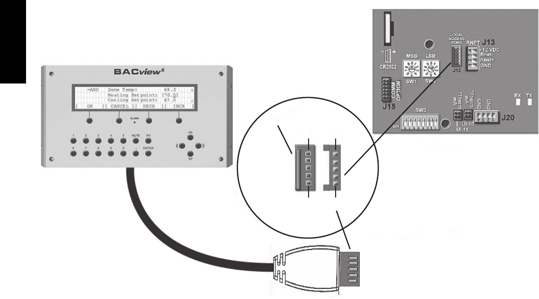
40
Local Access —
BACview6Handheld: The BACview6is a keypad/display
interface used to connect to the RTU Open to access the
control information, read sensor values, and test the RTU,
see Fig. 79. This is an accessory interface that does not
come with the RTU Open controller and can only be used
at the unit. Connect the BACview6to the RTU Open’s J12
local access port. There are 2 password protected levels in
the display (User and Admin). The user password is
defaulted to 0000 but can be changed. The Admin
password is 1111 and cannot be changed. There is a 10
minute auto logout if a screen is idle. See Form
48--50HCTQ--01T, Appendix A for navigation and screen
content.
Virtual BACview: Virtual BACview is a freeware computer
program that functions as the BACview6Handheld. The
USB Link interface (USB--L) is required to connect a
computer to the RTU Open board. The link cable connects
a USB port to the J12 local access port. This program
functions and operates identically to the handheld.
RTU Open Troubleshooting —
Communication LEDs: The LEDs indicate if the
controller is speaking to the devices on the network. The
LEDs should reflect communication traffic based on the
baud rate set. The higher the baud rate the more solid the
LEDs will appear. See Table 9.
Cable
Access Port
J12
P1 P1
P5 P5
RTU Open
BACview6 Local Access Cable
Protocol Selector
C10812
Fig. 79 -- BACview6Handheld Connections
48TC**16
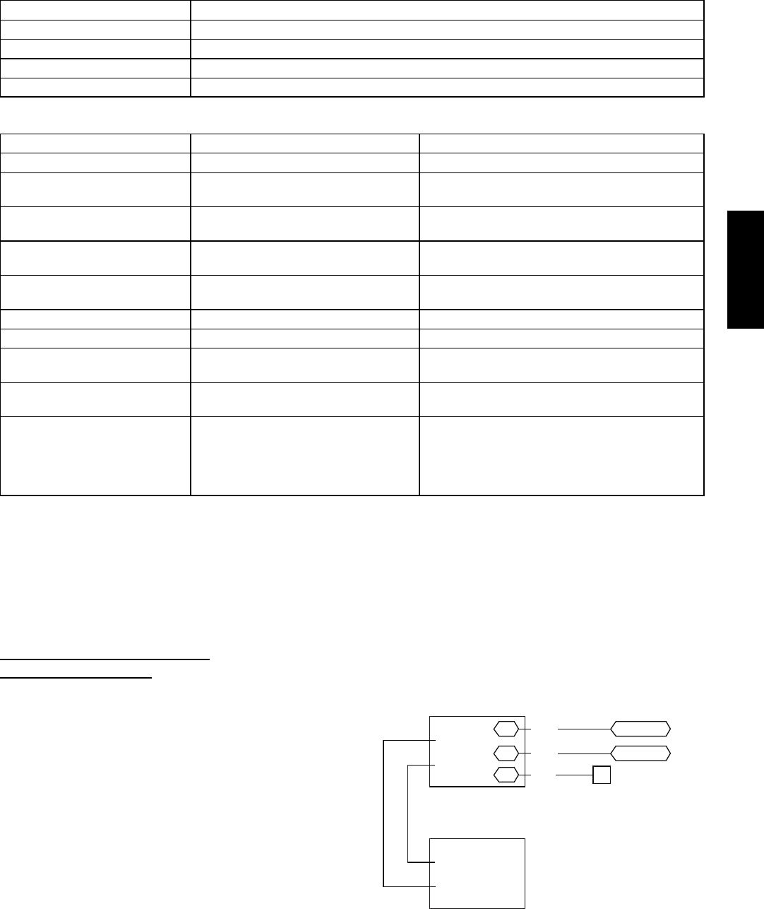
41
Table 9 – LEDs
The LEDs on the RTU Open Control Board (see Fig. 65) show the status of certain functions:
If this LED is on... Status is...
Power RTU Open has power
Rx RTU Open is receiving data from the network segment
Tx RTU Open is transmitting data over the network segment
DO# The digital output is active
The Run and Error LEDs indicate control module and network status
If Run LED shows... And Error LED shows... Status is...
2 flashes per second Off Normal
2 flashes per second 2flashes,
alternating with Run LED Five minute auto---restart delay after system error
2 flashes per second 3flashes,
then off Control module has just been formatted
2 flashes per second 4flashes,
then pause
Two or more devices on this network have the
same ARC156 network address
2 flashes per second On Exec halted after frequent system errors or
control programs halted
5 flashes per second On Exec start---up aborted, Boot is running
5 flashes per second Off Firmware transfer in progress, Boot is running
7 flashes per second 7 flashes per second, alternating with
Run LED Ten second recovery period after brownout
14 flashes per second 14 flashes per second,
alternating with Run LED Brownout
On On
Failure. Try the following solutions:
STurnRTUOpenoff,thenon.
SFormat RTU Open.
SDownload memory to RTU Open.
SReplace RTU Open.
NOTE: Refer to Catalog No. 48--50HCTQ--01T for
complete configuration of RTU Open, operating sequences
and troubleshooting information. Refer to RTU Open
Controller Integration Guide (Catalog No. 11--808--428--01)
for details on configuration and troubleshooting of connected
networks. Have a copy of these manuals available at unit
start--up.
Outdoor Air Enthalpy Control
(PNO 33CSENTHSW)
The enthalpy control (33CSENTHSW) is available as a
field--installed accessory to be used with the EconoMi$er2
damper system. The outdoor air enthalpy sensor is part of
the enthalpy control. (The separate field--installed
accessory return air enthalpy sensor (33CSENTSEN) is
required for differential enthalpy control. See Fig. 80.)
Locate the enthalpy control in the economizer next to the
Actuator Motor. Locate two GRA leads in the factory
harness and connect the gray lead labeled “ESL” to the
terminal labeled “LOW”. See Fig. 80. Connect the
enthalpy control power input terminals to economizer
actuator power leads RED (connect to 24V) and BLK
(connect to GND).
The outdoor enthalpy changeover setpoint is set at the
enthalpy controller.
Differential Enthalpy Control —
Differential enthalpy control is provided by sensing and
comparing the outside air and return air enthalpy conditions.
Install the outdoor air enthalpy control as described above.
Add and install a return air enthalpy sensor.
Return Air Enthalpy Sensor —
Mount the return--air enthalpy sensor (33CSENTSEN) in the
return--air section of the economizer. The return air sensor is
wired to the enthalpy controller (33CSENTHSW). See
Fig. 80.
GRA
BLK
RED
– 4-20
Main
+ VDC
Out
– 4-20 Main
Out
+ 24-36
VDC In
LOW
GND
24V
7
PL6-1 (24-V)
PL6-4 (COM)
Outside Air
Enthalpy Switch
Return Air
Enthalpy
Sensor
CTB ECON
(P’LINK: to J4-2) or
(RTU Open: to J2-6)
C11161
Fig. 80 -- Outside and Return Air Enthalpy Sensor
Wiring
48TC**16
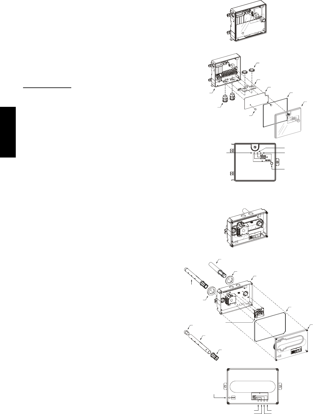
42
To wire the return air enthalpy sensor, perform the
following:
1. Use a 2--conductor, 18 or 20 AWG, twisted pair cable
to connect the return air enthalpy sensor to the en-
thalpy controller.
2. Connect the field--supplied RED wire to (+) spade con-
nector on the return air enthalpy sensor and the (+) ter-
minal on the enthalpy controller. Connect the BLK wire
to (--) spade connector on the return air enthalpy sensor
and the (--) terminal on the enthalpy controller.
Smoke Detectors
Smoke detectors are available as factory--installed options on
48TC**16 units. Smoke detectors may be specified for
Supply Air only or for Return Air without or with
economizer or in combination of Supply Air and Return Air.
Return Air smoke detectors are arranged for vertical return
configurations only. All components necessary for operation
are factory--provided and mounted. The unit is
factory--configured for immediate smoke detector shutdown
operation; additional wiring or modifications to unit terminal
board may be necessary to complete the unit and smoke
detector configuration to meet project requirements.
Units equipped with factory--optional Return Air smoke
detectors require a relocation of the sensor module at unit
installation. See “Completing Installation of Return Air
Smoke Sensor:” on page 37 for details.
System —
The smoke detector system consists of a four--wire
controller and one or two sensors. Its primary function is
to shut down the rooftop unit in order to prevent smoke
from circulating throughout the building. It is not to be
used as a life saving device.
Controller —
The controller (see Fig. 81) includes a controller housing,
a printed circuit board, and a clear plastic cover. The
controller can be connected to one or two compatible duct
smoke sensors. The clear plastic cover is secured to the
housing with a single captive screw for easy access to the
wiring terminals. The controller has three LEDs (for
Power, Trouble and Alarm) and a manual test/reset button,
all located on the cover face.
Sensor Module —
The sensor module (see Fig. 82) includes a plastic housing, a
printed circuit board, a clear plastic cover, a sampling tube
inlet and an exhaust tube. The sampling tube (when used)
and exhaust tube are attached during installation. The
sampling tube varies in length depending on the size of the
rooftop unit. The clear plastic cover permits visual
inspections without having to disassemble the sensor. The
cover attaches to the sensor housing using four captive
screws and forms an airtight chamber around the sensing
electronics. Each sensor includes a harness with an RJ45
terminal for connecting to the controller. Each sensor has
four LEDs (for Power, Trouble, Alarm and Dirty) and a
manual test/reset button (on the left--side of the housing).
Duct smoke sensor
controller
Fastener
(2X)
Controller cover
Conduit nuts
(supplied by installer)
Conduit support plate
Cover gasket
(ordering option)
Conduit couplings
(supplied by installer)
Terminal block cover
Controller housing
and electronics
Alarm Power
Test/reset
switch
Trouble
C08208
Fig. 81 -- Controller Assembly
Duct smoke sensor
See
Detail A
Exhaust tube
Plug
Sampling tube
(ordered separately)
Intake
gasket Cover gasket
(ordering option)
TSD-CO2
(ordering option)
Sensor housing
and electronics
Exhaust gasket
Coupling
Sensor cover
Detail A
Magnetic
test/reset
switch
Alarm
Trouble
Power
Dirty
C08209
Fig. 82 -- Smoke Detector Sensor Module
48TC**16
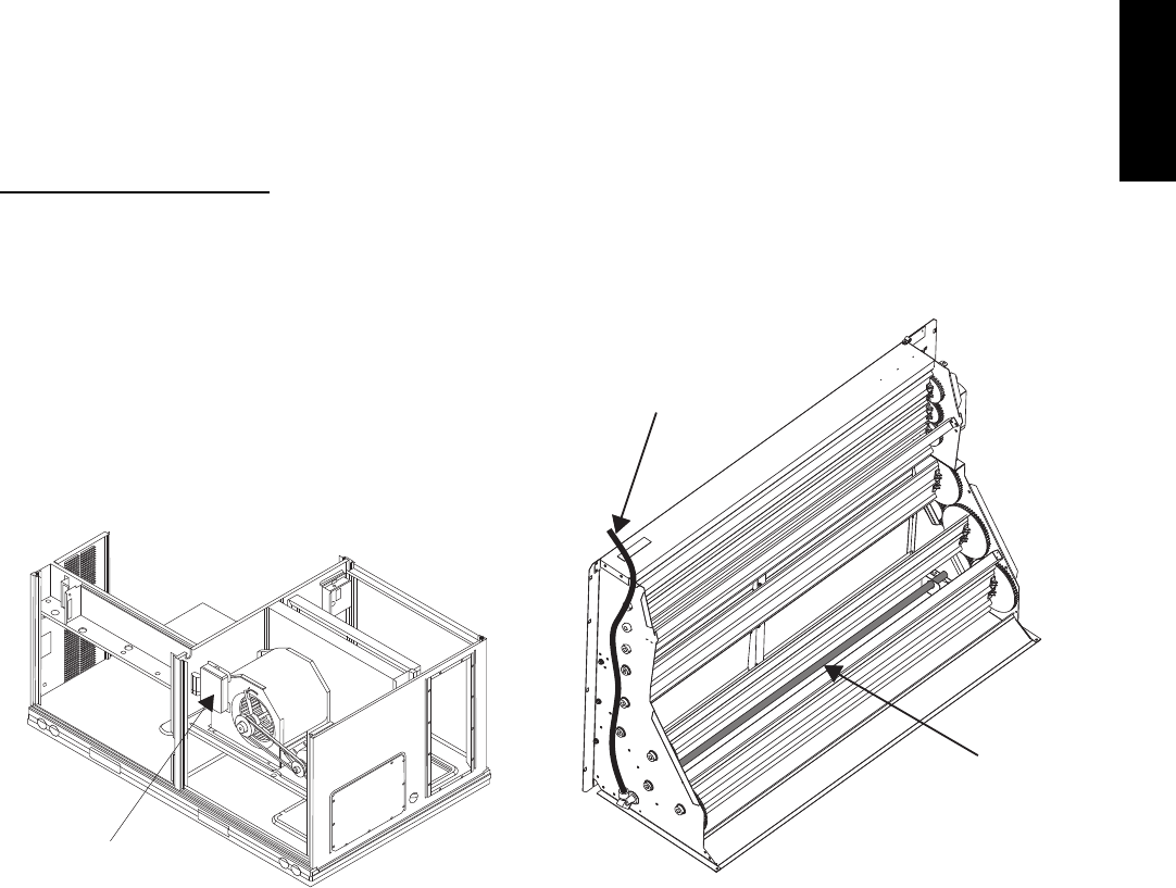
43
Air is introduced to the duct smoke detector sensor’s
sensing chamber through a sampling tube that extends into
the HVAC duct and is directed back into the ventilation
system through a (shorter) exhaust tube. The difference in
air pressure between the two tubes pulls the sampled air
through the sensing chamber. When a sufficient amount of
smoke is detected in the sensing chamber, the sensor
signals an alarm state and the controller automatically
takes the appropriate action to shut down fans and
blowers, change over air handling systems, notify the fire
alarm control panel, etc.
The sensor uses a process called differential sensing to
prevent gradual environmental changes from triggering
false alarms. A rapid change in environmental conditions,
such as smoke from a fire, causes the sensor to signal an
alarm state but dust and debris accumulated over time
does not.
For installations using two sensors, the duct smoke
detector does not differentiate which sensor signals an
alarm or trouble condition.
Smoke Detector Locations
Supply Air —
The Supply Air smoke detector sensor is located to the
left of the unit’s indoor (supply) fan. See Fig. 83. Access
is through the left side blower access panel. There is no
sampling tube used at this location. The sampling tube
inlet extends through the side plate of the fan housing
(into a high pressure area). The controller is located on a
bracket to the right of the return filter, accessed through
the lift--off filter panel.
Smoke Detector Sensor
C08245
Fig. 83 -- Typical Supply Air Smoke Detector Sensor
Location
Return Air without Economizer —
The sampling tube is located across the return air opening
on the unit basepan. See Fig. 86. The holes in the
sampling tube face downward, into the return air stream.
The sampling tube is connected via tubing to the return air
sensor that is mounted on a bracket high on the partition
between return filter and controller location. (This sensor
is shipped in a flat--mounting location. Installation
requires that this sensor be relocated to its operating
location and the tubing to the sampling tube be connected.
See “Completing Installation of Return Air Smoke
Sensor:” for details.)
Return Air with Economizer —
The sampling tube is inserted through the side plates of
the economizer housing, placing it across the return air
opening on the unit basepan. See Fig. 84. The holes in the
sampling tube face downward, into the return air stream.
The sampling tube is connected via tubing to the return air
sensor that is mounted on a bracket high on the partition
between return filter and controller location. (This sensor
is shipped in a flat--mounting location. Installation
requires that this sensor be relocated to its operating
location and the tubing to the sampling tube be connected.
See the following installation procedure.)
Return Air
Sampling Tube
Flexible
Exhaust Tube
C10330
Fig. 84 -- Return Air Sampling Tube Location
48TC**16
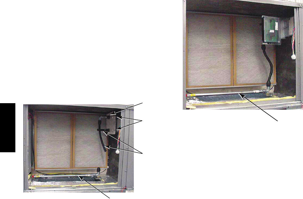
44
Completing Installation of Return Air Smoke Sensor:
1. Unscrew the two screws holding the Return Air
Sensor detector plate. See Fig. 85. Save the screws.
2. Remove the Return Air Sensor and its detector plate.
3. Rotate the detector plate so the sensor is facing out-
wards and the sampling tube connection is on the bot-
tom. See Fig. 86.
4. Screw the sensor and detector plate into its operating
position using screws from Step 1. Make sure the
sampling tube connection is on the bottom and the ex-
haust tube is on the top. See Fig. 86.
5. Connect the flexible tube on the sampling inlet to the
sampling tube on the basepan.
Controlle
r
Screws
Flexible
Exhaust
Tubes
Sampling Tube
C10331
Fig. 85 -- Return Air Detector Shipping Position
Sampling Tube
C10332
Fig. 86 -- Return Air Sensor Operating Position
Additional Application Data —
Refer to Catalog No. HKRNKA--1XA for discussions on
additional control features of these smoke detectors
including multiple unit coordination.
48TC**16
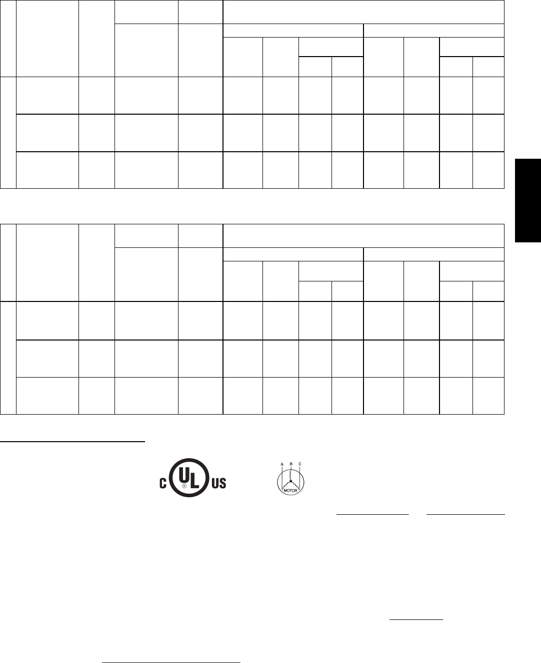
45
Table 10 – Unit Wire/Fuse or HACR Breaker Sizing Data
UNIT
NOM.
V --- P h --- H z
IFM
TYPE
COMBUSTION
FAN MOTOR
POWER
EXHAUST NO C.O. or UNPWR C.O.
FLA FLA
NO P.E. w/ P.E. (pwrd fr/ unit)
MCA
FUSE
or
HACR
BRKR
DISC. SIZE
MCA
FUSE
or
HACR
BRKR
DISC. SIZE
FLA LRA FLA LRA
48TC*D16
208/230---3---60
STD
0.48 3.8
68.3 80 71 396 72.1 80 76 400
MED 70.8 80 74 413 74.6 90 79 417
HIGH 81.2 100 86 432 85.0 100 91 436
4 6 0 --- 3 --- 6 0
STD
0.25 1.8
34 45 35 234 35.8 45 37 236
MED 35.0 45 37 243 36.8 45 39 245
HIGH 40.8 50 43 252 42.6 50 45 254
5 7 5 --- 3 --- 6 0
STD
0.24 3.8
26.5 30 28 184 30.3 40 32 188
MED 26.5 30 28 184 30.3 40 32 188
HIGH 32.7 40 35 196 36.5 45 39 200
Table 10 — Unit Wire/Fuse or HACR Breaker Sizing Data (cont)
UNIT
NOM.
V --- P h --- H z
IFM
TYPE
COMBUSTION
FAN MOTOR
POWER
EXHAUST w/ PWRD C.O.
FLA FLA
NO P.E. w/ P.E. (pwrd fr/ unit)
MCA
FUSE
or
HACR
BRKR
DISC. SIZE
MCA
FUSE
or
HACR
BRKR
DISC. SIZE
FLA LRA FLA LRA
48TC*D16
208/230---3---60
STD
0.48 3.8
73.1 80 77 401 76.9 100 81 405
MED 75.6 100 80 418 79.4 100 84 422
HIGH 86.0 100 92 437 89.8 100 96 441
4 6 0 --- 3 --- 6 0
STD
0.25 1.8
36.2 45 38 236 38 50 40 238
MED 37.2 50 39 245 39.0 50 41 247
HIGH 43.0 50 46 254 44.8 50 48 256
5 7 5 --- 3 --- 6 0
STD
0.24 3.8
28.2 35 30 186 32 40 34 190
MED 28.2 35 30 186 32 40 34 190
HIGH 34.4 40 37 198 38.2 45 41 202
Legend and Notes for Table 10
LEGEND:
BRKR --- Circuit breaker
CO --- Convenience outlet
DISC --- Disconnect
FLA --- Full load amps
IFM --- Indoor fan motor
LRA --- Locked rotor amps
MCA --- Minimum circuit amps
P. E . --- P o w e r e x h a u s t
PWRD CO --- Powered convenient outlet
UNPWR CO --- Unpowered convenient outlet
NOTES:
1. In compliance with NEC requirements for multimotor and
combination load equipment (refer to NEC Articles 430 and
440), the overcurrent protective device for the unit shall be
fuse or HACR breaker. Canadian units may be fuse or circuit
breaker.
2. Unbalanced 3-Phase Supply Voltage
Never operate a motor where a phase imbalance in supply
voltage is greater than 2%. Use the following formula to de-
termine the percentage of voltage imbalance.
% Voltage Imbalance = 100 x
max voltage deviation from average voltage
average voltage
Example: Supply voltage is 230-3-60
AB = 224 v
BC = 231 v
AC = 226 v
Average Voltage = (224 + 231 + 226) =681
33
= 227
Determine maximum deviation from average voltage.
(AB) 227 – 224 = 3 v
(BC) 231 – 227 = 4 v
(AC) 227 – 226 = 1 v
Maximum deviation is 4 v.
Determine percent of voltage imbalance.
% Voltage Imbalance = 100 x 4
227
= 1.76%
This amount of phase imbalance is satisfactory as it is below the
maximum allowable 2%.
IMPORTANT: If the supply voltage phase imbalance is more than
2%, contact your local electric utility company immediately.
48TC**16
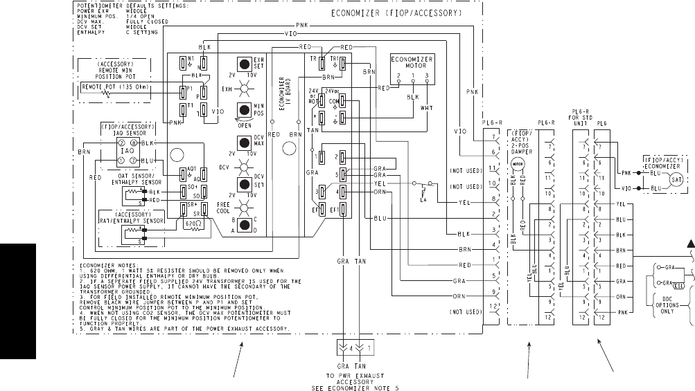
46
Economizer 2 Position Damper Unit Without Economizer or
2 Position Damper
C10333
Fig. 87 -- EconoMi$ertIV Wiring
Step 13 — Adjust Factory--Installed Options
Smoke Detectors —
Smoke detector(s) will be connected at the Central Terminal
Board (CTB), at terminals marked “Smoke Shutdown”.
Remove jumper JMP 3 when ready to energize unit.
EconoMi$er IV Occupancy Switch —
Refer to Fig. 87 for general EconoMi$er IV wiring.
External occupancy control is managed through a
connection on the Central Terminal Board.
If external occupancy control is desired, connect a time
clock or remotely controlled switch (closed for Occupied,
open for Unoccupied sequence) at terminals marked
OCCUPANCY on CTB. Remove or cut jumper JMP 2 to
complete the installation.
Step 14 — Install Accessories
Available accessories include:
Roof Curb (must be installed before unit)
Thru--base connection kit (must be installed before unit
is set on curb)
Manual outside air damper
Two--Position motorized outside air damper
EconoMi$er IV (with control and integrated barometric
relief)
EconoMi$er2 (without control/for external signal and
integrated barometric relief)
Barometric relief
Power Exhaust
Differential dry--bulb sensor (EconoMi$er IV)
Outdoor enthalpy sensor
Differential enthalpy sensor
Time Guard II compressor anti--cycle control
Outdoor coil protector grille
Head pressure control
Programmable setback thermostat
Electrical/Mechanical thermostat and subbase
Thermidistattdevice
Humidistat
Thermostat / Sensors
CO2sensor
DDC interface (PremierLink)
Louvered hail guard
Phase monitor control
Refer to separate installation instructions for information
on installing these accessories.
Pre--Start and Start--Up
This completes the mechanical installation of the unit.
Refer to the unit’s Service Manual for detailed Pre--Start
and Start--up instructions.
48TC**16

47
48TC**16

48
Copyright 2011 Carrier Corp. D7310 W. Morris St. DIndianapolis, IN 46231 Printed in U.S.A. Edition Date: 05/11
Manufacturer reserves the right to change, at any time, specifications and designs without notice and without obligations.
Catalog No: 48TC---14SI
Replaces: 48TC--- 11SI
48TC**16
