Carrier 52C Users Manual
P to the manual ba181c70-2caa-4191-9d65-c756ecd90630
2015-01-24
: Carrier Carrier-52C-Users-Manual-310576 carrier-52c-users-manual-310576 carrier pdf
Open the PDF directly: View PDF ![]() .
.
Page Count: 52
52C,P
SERIES
PTAC Customer Support Center
1•800•894•6449
SERVICE TECHNICIAN GUIDE
PACKAGED TERMINAL AIR CONDITIONERS
AND HEAT PUMPS
CONTENTS Page
INTRODUCTION. . . . . . . . . . . . . . . . . . . . . . . . . . . . . . .2,3
SUMMARY OF DANGERS, WARNINGS,
AND CAUTIONS . . . . . . . . . . . . . . . . . . . . . . . . . . . . . . 2
UNIT DISASSEMBLY . . . . . . . . . . . . . . . . . . . . . . . . . . .3,4
TOOLS NEEDED. . . . . . . . . . . . . . . . . . . . . . . . . . . . . . . 3
REMOVE FRONT PANEL . . . . . . . . . . . . . . . . . . . . . . . 3
DISCONNECT POWER FOR
CORD-CONNECTED UNIT . . . . . . . . . . . . . . . . . . . . . 3
DISCONNECT POWER FOR PERMANENTLY
CONNECTED (HARDWIRED) UNITS . . . . . . . . . . . . 3
OPEN THE CONTROL BOX. . . . . . . . . . . . . . . . . . . . . 4
REMOVE THE UNIT FROM THE WALL SLEEVE . . 4
ACCESSING UNIT COMPONENTS . . . . . . . . . . . . . .5-8
ACCESSING INDOOR-AIR SECTION
COMPONENTS. . . . . . . . . . . . . . . . . . . . . . . . . . . . . . . . 5
ACCESSING OUTDOOR-AIR SECTION
COMPONENTS. . . . . . . . . . . . . . . . . . . . . . . . . . . . . . . . 5
REINSTALL FRONT PANEL. . . . . . . . . . . . . . . . . . . . . 8
GENERAL CLEANING . . . . . . . . . . . . . . . . . . . . . . . . .9-12
CLEANING AND SAFETY . . . . . . . . . . . . . . . . . . . . . . 9
TOOLS NEEDED. . . . . . . . . . . . . . . . . . . . . . . . . . . . . . 10
MONTHLY CLEANING. . . . . . . . . . . . . . . . . . . . . . . . 10
SEASONAL CLEANING . . . . . . . . . . . . . . . . . . . . . . . 11
COMPRESSOR . . . . . . . . . . . . . . . . . . . . . . . . . . . . . . .13-17
COMPRESSOR TROUBLESHOOTING. . . . . . . . . . . 14
BASIC HERMETIC COMPRESSOR
ELECTRICAL MEASUREMENTS . . . . . . . . . . . . . . . 14
COMPRESSOR REPLACEMENT. . . . . . . . . . . . . . . . 15
Page
HEATERS. . . . . . . . . . . . . . . . . . . . . . . . . . . . . . . . . . . . 18,19
COMMON CAUSES OF HEATER FAILURE. . . . . . . 18
HEATER REMOVAL . . . . . . . . . . . . . . . . . . . . . . . . . . . 18
OPERATING CONTROLS. . . . . . . . . . . . . . . . . . . . . 20-28
UNIT-MOUNTED CONTROLS. . . . . . . . . . . . . . . . . . 20
WALL-MOUNTED THERMOSTAT CONTROLS. . . 21
REMOTE THERMOSTAT
TROUBLESHOOTING . . . . . . . . . . . . . . . . . . . . . . . . . 21
DESCRIPTION OF SELECTOR
SWITCH SETTINGS . . . . . . . . . . . . . . . . . . . . . . . . . . . 23
NON-USER ADJUSTABLE CONTROLS . . . . . . . . . . 23
SEQUENCE OF OPERATION . . . . . . . . . . . . . . . . . . . 24
COMPONENT OPERATION AND
TROUBLESHOOTING . . . . . . . . . . . . . . . . . . . . . . . . . 24
ELECTRICAL COMPONENTS REMOVAL
AND REPLACEMENT . . . . . . . . . . . . . . . . . . . . . . . . . 27
FAN MOTOR . . . . . . . . . . . . . . . . . . . . . . . . . . . . . . . . 29-31
FAN MOTOR TROUBLESHOOTING. . . . . . . . . . . . . 29
BASIC FAN MOTOR ELECTRICAL TESTS. . . . . . . . 29
FAN MOTOR REPLACEMENT. . . . . . . . . . . . . . . . . . 31
FIELD TEMPERATURE CHARTS . . . . . . . . . . . . . . 32-40
WIRING DIAGRAMS . . . . . . . . . . . . . . . . . . . . . . . . 41-45
MOST FREQUENT PTAC SERVICE
QUESTIONS. . . . . . . . . . . . . . . . . . . . . . . . . . . . . . . . . . . . 46
ACCESSORIES. . . . . . . . . . . . . . . . . . . . . . . . . . . . . . . . . .47
52C PERFORMANCE AND PHYSICAL DATA. . . . . . 48
52P PERFORMANCE AND PHYSICAL DATA. . . . . . 49
52C,P
SERIES
2
INTRODUCTION
The focus of this manual is to provide basic information
on service procedures, safety, troubleshooting, clean-
ing, and component replacement for service techni-
cians. It is intended for use only by HVAC service
technicians who have successfully completed
instruction and received Type I Certification
from the U.S. Environmental Protection Agency.
The instructions in this manual are general in nature
and are not to be substituted for installation and ser-
vice instructions shipped with the unit. No attempt to
install, operate, adjust, repair, or dismantle any equip-
ment should be made until the manufacturer’s instruc-
tions are read and thoroughly understood by the
service technician. Even equipment that seems famil-
iar may have specific model differences from year to
year. Always review manufacturer’s instructions.
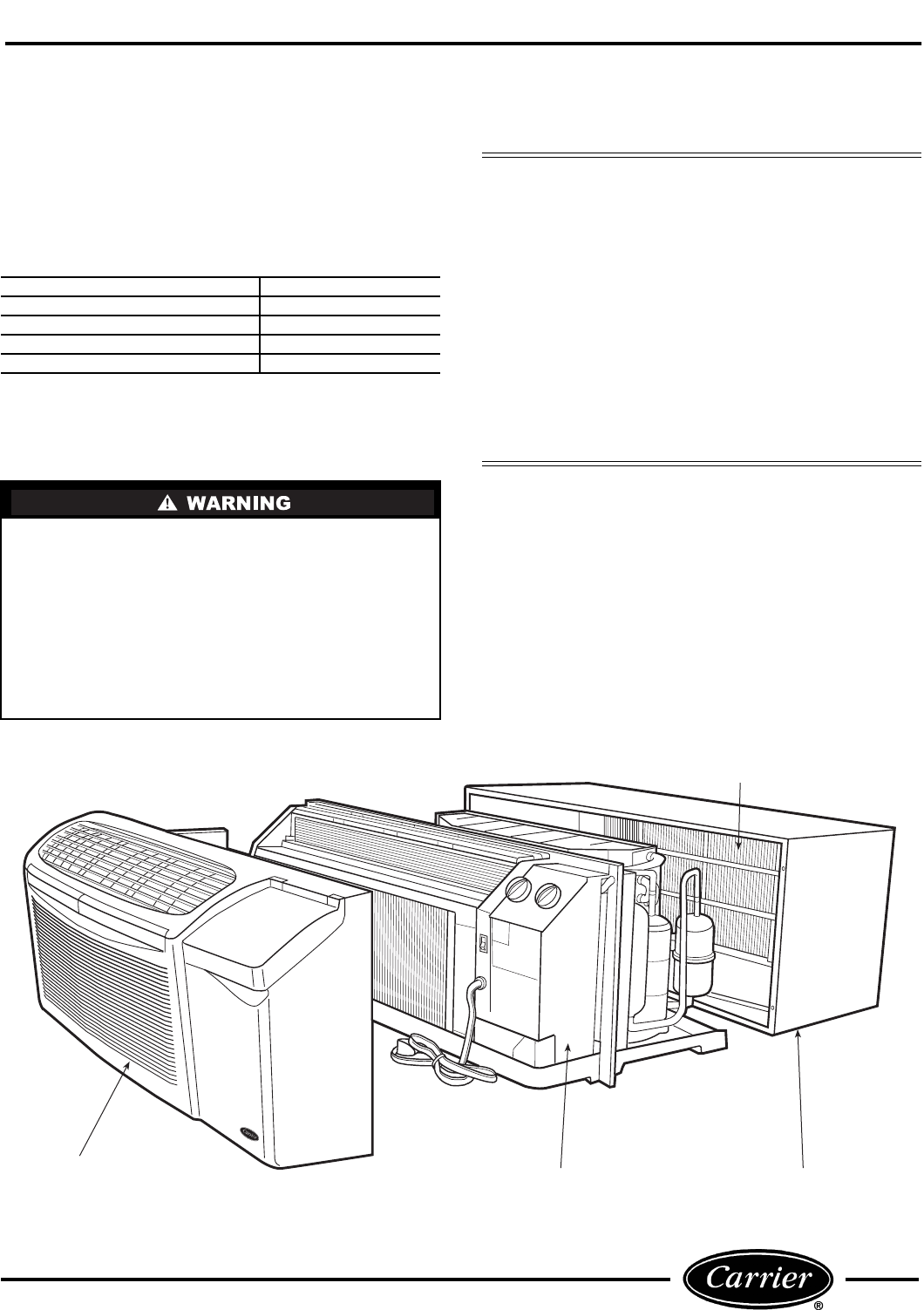
Model 52C,P packaged terminal air conditioner
(PTAC) and heat pump units are self-contained for
installation through the wall for individual room heat-
ing and cooling. The Model 52C,P polymer and metal
sleeves are permanently fastened to the wall; the unit
chassis slides out of the sleeve to allow the service
technician easy access. Many accessories are offered
to complement the unit’s performance and comfort
control.
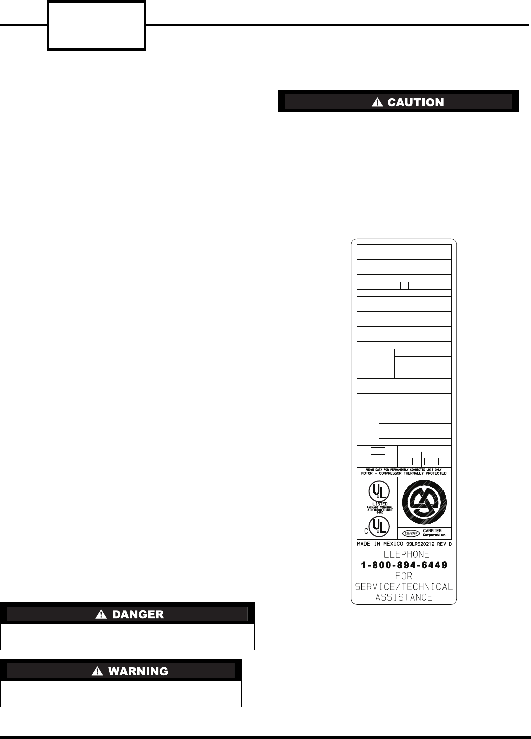
Before beginning any service procedures, it is impor-
tant to check the unit model number. See Figure 1 and
2. Units that seem similar may have subtle differences
that could affect service procedures. The following
units are covered in this manual:
52CE — 60 Hz cooling with electric heat units
52CQ — 60 Hz heat pump with electric heat units
52PE — 60 Hz cooling with electric heat units
52PQ — 60 Hz heat pump with electric heat units
52PC — 60 Hz cooling only units
Knowing which model is being serviced will help deter-
mine if the unit is performing at optimum levels. The
model number is located on the data information plate
beneath the front panel of the unit. See Figure 1. The
data information plate also lists voltage ranges and
other important electrical information about the unit.
SUMMARY OF DANGERS, WARNINGS,
AND CAUTIONS
The terms DANGER, WARNING, and CAUTION have
specific meanings that identify the degree of hazard.
Typically in the HVAC industry, these specific mean-
ings are:
There is an immediate hazard which WILL result
in severe personal injury or death.
Hazards or unsafe practices which COULD
result in severe personal injury or death.
Potential hazards or unsafe practices which
COULD result in minor personal injury or equip-
ment damage.
CANADIAN INSTALLATION
SERIAL 3701X11520
DATE OF MFG. 09/12/2001
VOLT RANGE 187-253
VOLTS 230/208
PH 1
MODEL 52PQA312301AA
HZ 60
MIN CKT AMPACITY 19.3
R-22 OZ 34
DESIGN PSIG 350 HIGH SIDE, 150 LOW SIDE
COOLING
HEATING
BTU/HR 12,100/12,000
AMPS 4.8/5.3
WATTS 1090/1122
EER 11.1/10.7
MOTOR
FAN
COMP
HP
FLA
RLA
LRA
6.1
29
0.75
1/8
BTU/HR 11,000/11,000
AMPS 15.6/14.5
WATTS 3570/2997
COP 3.2/3.2
HEATER
BTU/HR
AMPS 14.8/13.7
WATTS 3400/2850
WATER
STEAM
20
20 20
USE
TIME DELAY FUSE
OR HACR TYPE
CIRCUIT BREAKER
AMP
AMP AMP
MAX FUSE MAX BREAKER
FIGURE 1 — SAMPLE DATA INFORMATION
PLATE
3
UNIT DISASSEMBLY
This section includes common procedures for disas-
sembly and re-assembly of unit.
TOOLS NEEDED
The following field-supplied items are recommended
for general disassembly of the unit:
• Flat head screw driver
•5/16-in. nut driver
• Safety glasses
• Needle nose pliers
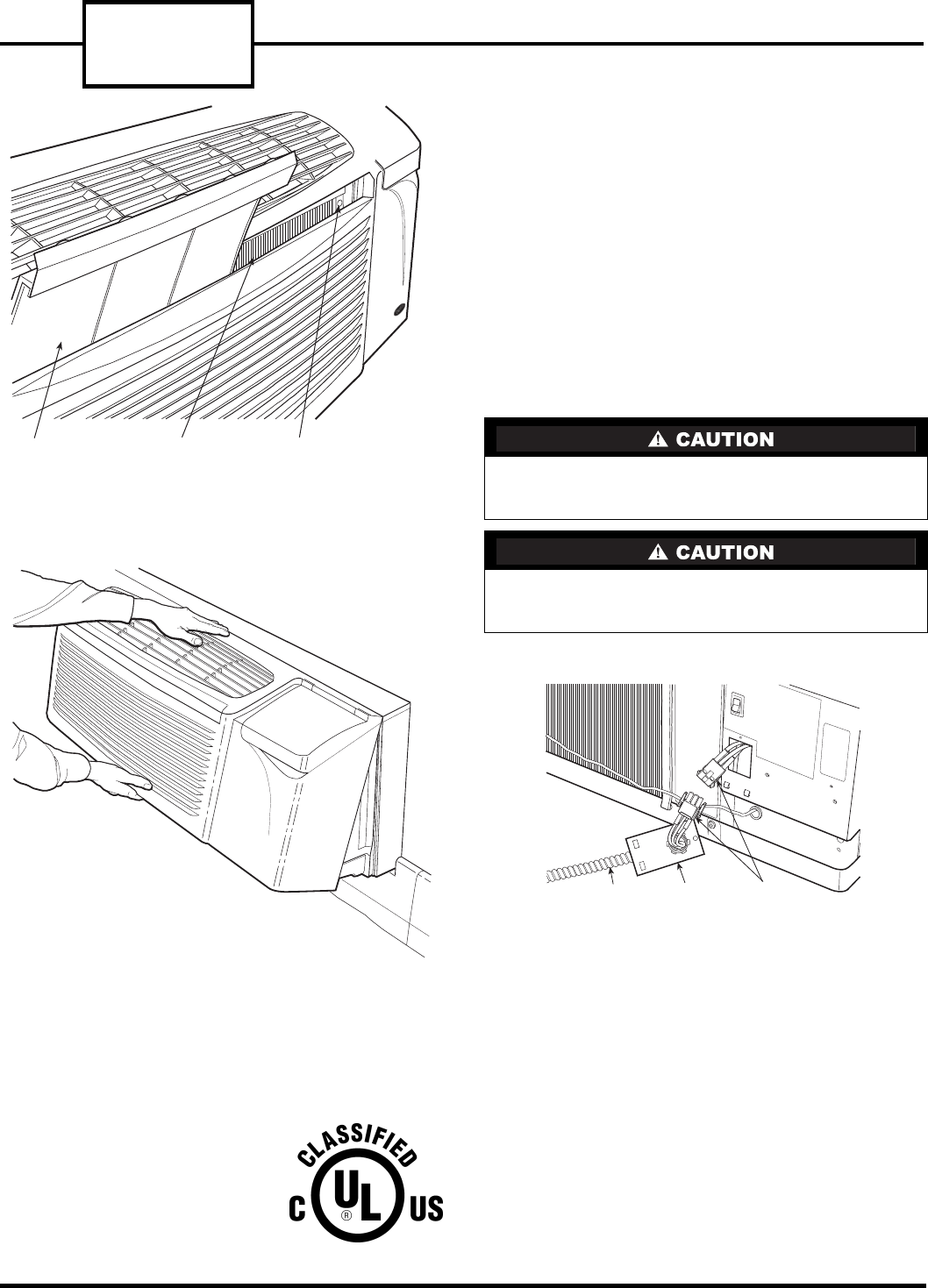
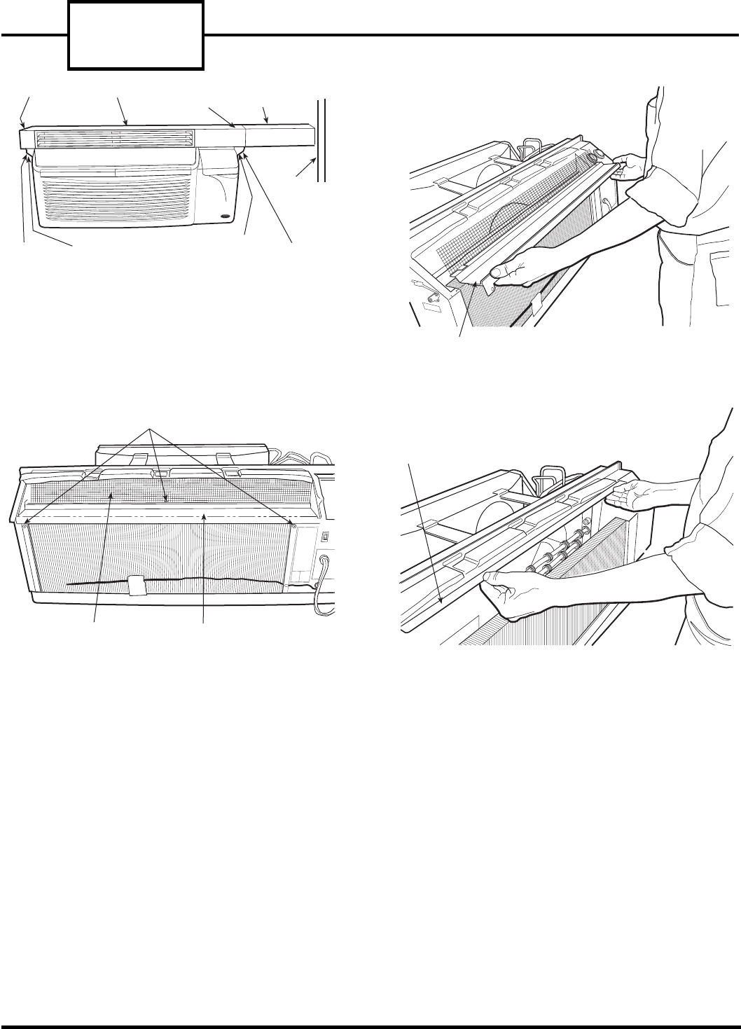
REMOVE FRONT PANEL
NOTE: Before removing front panel, remove 2 locking
screws (if installed) located behind the filter handles.
See Figure 3. If a lateral duct accessory is installed, the
plenum must be removed before removing the front
panel. Refer to Remove Lateral Duct Extension section
for removal instructions.
1. Grasp the front panel firmly at the center of the
top and bottom of the panel.
2. Pull the panel upward at the bottom and forward
at the top to release magnetic latches and partition
hooks. See Figure 4.
DISCONNECT POWER FOR
CORD-CONNECTED UNIT
1. Turn selector switch to OFF position.
2. Open the disconnect switch at main power supply.
Use proper Lockout and Tag procedures.
3. Unplug the unit service cord.
DISCONNECT POWER FOR
PERMANENTLY CONNECTED
(HARDWIRED) UNITS
1. Turn selector switch to OFF position.
2. Open the disconnect switch at main power supply.
Use proper Lockout and Tag procedures.
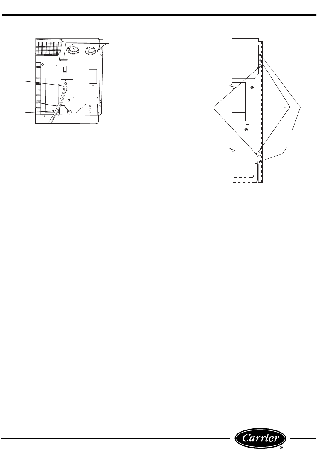
3. Remove screw from access cover and remove
access cover.
4. Pull out the plug assembly and disconnect. See
Figure 5.
IMPORTANT: Follow manufacturer’s instruc-
tions when disassembling and re-assembling a
unit for cleaning, maintenance, or part replace-
ment. When disassembling wiring, it is strongly
recommended that numbered stickers be
attached to identify leads and terminals to aid in
the re-assembly process. Always review safety
procedures prior to the start of a job.
Prior to servicing electrical equipment, discon-
nect all power to avoid electric shock! Tag all dis-
connects. Never alter cord or plug and do not use
extension cords.
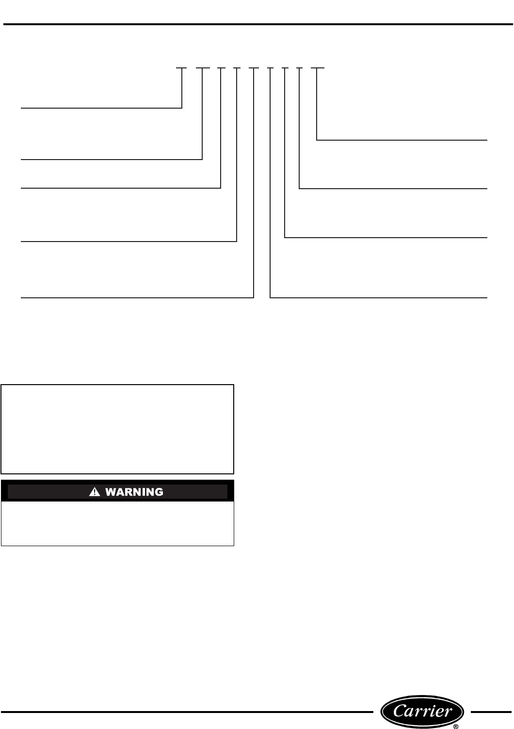
Electrical Data
3 – 230/208-v, 60 Hz
4 – 265-v, 60 Hz
Cooling Capacity (nominal)
07 – 7,000 Btuh
09 – 9,000 Btuh
12 – 12,000 Btuh
15 – 15,000 Btuh
52 PQ A 3 12 3 0 1 AA
Series Designation
PTAC (Packaged Terminal Air Conditioner)
Non-Performance
Changes 0-9
Chassis Options
Blank or AA – Standard
CP – Corrosion Protection
RC – Wall Thermostat Control
RP – Wall Thermostat Control with
Corrosion Protection
CE – Cooling with Electric Heat
CQ – Heat Pump with Electric Heat
PC – Cooling Only
PE – Cooling with Electric Heat
PQ – Heat Pump with Electric Heat
Packaging
1 – Domestic
Latest Revision
A – Z
Electric Heater Size
0 – No Heating (Cooling Only Model)
2 – 2.3 kW
3 – 3.4 kW
5 – 5.0 kW
FIGURE 2 — MODEL NUMBER NOMENCLATURE
52C,P
SERIES
4
OPEN THE CONTROL BOX
The control box is factory wired. To open the box,
remove the 2 screws on the top of the control box and
lower the front hinged panel. See Figure 6.
REMOVE THE UNIT FROM THE
WALL SLEEVE
1. Remove the four mounting screws that secure the
PTAC unit to the wall sleeve (2 screws per side).
See Figure 7.
2. Grasp the sides of the unit and slide it from the
sleeve.
NOTE: The mounting screws may be in a different
location depending on brand of wall sleeve
attached.
The chassis weighs between 110 and 150 lbs. Take
proper safety precautions to avoid personal injury
when lifting and moving the chassis.
The unit basepan may have water in it. Tilt the
unit back slightly when removing it from the sleeve
to drain some of the water into the sleeve.
CONDUIT ACCESS
PANEL
MOLEX
PLUGS
FIGURE 5 — PLUG ASSEMBLY ON
HARDWIRE UNITS
REMOVABLE
FILTER
LOCATION OF
REMOVED FILTER
LOCKING SCREW
(NOTE: 2nd LOCKING SCREW
IS LOCATED BEHIND
2nd FILTER)
FIGURE 3 — LOCATION OF LOCKING SCREWS
BEHIND FILTERS
FIGURE 4 — REMOVING FRONT PANEL
eplacement Package Terminal Air Conditioner,
LASSIFIED BY UNDERWRITERS LABORATO-
IES INC., AS TO ELECTRIC SHOCK, FIRE AND
ASUALTY HAZARDS ONLY. FOR FIELD INSTAL-
ATION WITH EXISTING WALL SLEEVES, OUT-
OOR, LOUVERS, AND INDOOR PANELS AS
PECIFIED ON THE PRODUCT.
5
ACCESSING UNIT COMPONENTS
ACCESSING INDOOR-AIR SECTION
COMPONENTS
■ REMOVE LATERAL DUCT EXTENSION
ACCESSORY FOR UNITS EQUIPPED WITH THE
LATERAL DUCT
1. Remove the 2 top screws that secure the lateral
duct plenum to the top of the lateral duct exten-
sion. See Figure 8.
2. Locate and remove the 2 bottom bracket screws
(located opposite extension duct) that secure the
lateral duct plenum to the bracket flange. See
Figure 8.
3. Carefully lift the plenum up and away from front
panel and duct extension.
■ REMOVE THE DISCHARGE DECK ASSEMBLY
1. Remove the front panel. Refer to Remove Front
Panel section and Figure 4.
2. Remove discharge screen screw using a 5/16-in. nut
driver. See Figure 9.
3. Remove the discharge deck assembly screws using
a 5/16-in. nut driver. See Figure 9.
4. Gently pull the deck/grille up and away from the
unit.
5. Reassemble by reversing steps above.
■ ACCESSING THE HEATER ASSEMBLY — Once the
discharge deck assembly is removed, the Heater
Assembly should now be accessible. See Figure 10.
1. Using pliers, carefully remove all wires connected
to the heater assembly. Label each wire for ease of
re-assembly.
2. Gently pull the heater assembly up and away
from scroll. See Figure 11.
3. Reassemble by reversing steps above.
ACCESSING OUTDOOR-AIR SECTION
COMPONENTS
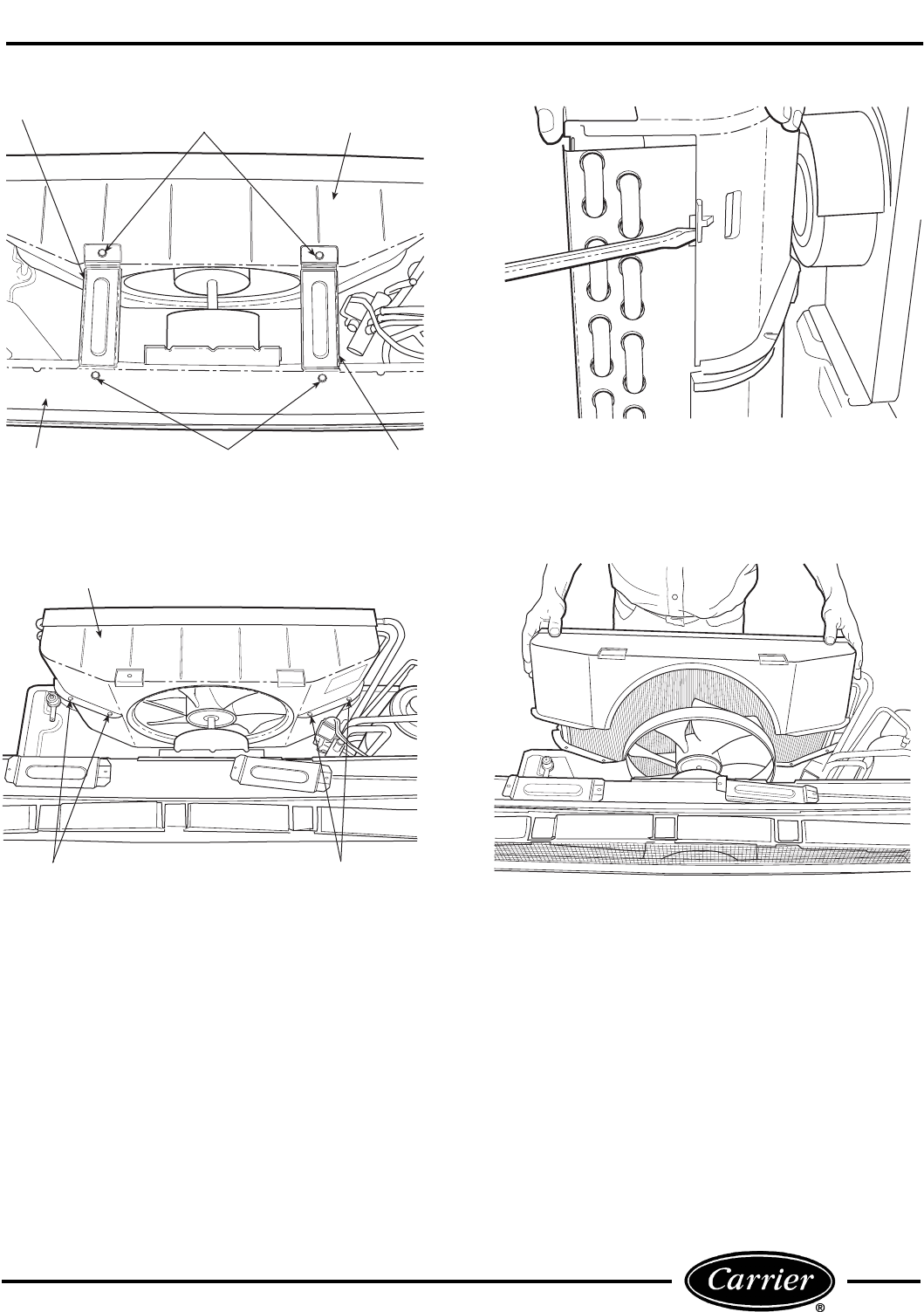
■ REMOVE THE GUSSETS (See Figure 12)
1. Remove the 2 screws on each side that secure the
gussets to the partition.
2. Remove the 2 screws that secure the gussets to
the plastic condenser orifice and remove the
gussets.
POWER
CORD
ACCESS
COVER
POWER
CORD
CONTROL
BOX
SCREWS
GE WALL
SLEEVE
HOLES
AMANA, TRANE
(SLOTTED
HOLES) WALL
SLEEVE HOLES
VARIOUS ATTACHMENT
HOLE LOCATIONS
CARRIER, BRYANT
WALL SLEEVE
HOLES
FIGURE 6 — CONTROL BOX COVER
FIGURE 7 — PTAC UNIT TO WALL
SLEEVE MOUNTING SCREWS
52C,P
SERIES
6
■ DETACH THE CONDENSER ORIFICE FROM THE
CONDENSER COIL
1. Remove top half of condenser orifice.
a. Unscrew the top half of the condenser orifice by
backing off the 4 captive screws. See Figure 13.
b. Using a flat head screwdriver, gently pry the
top half of the orifice from the tube sheets. See
Figure 14.
c. Remove top of condenser orifice. See Figure 15.
2. Remove bottom half of condenser orifice.
a. Using a flat head screwdriver, gently pry the
bottom half of the orifice from the tube sheets.
See Figure 14.
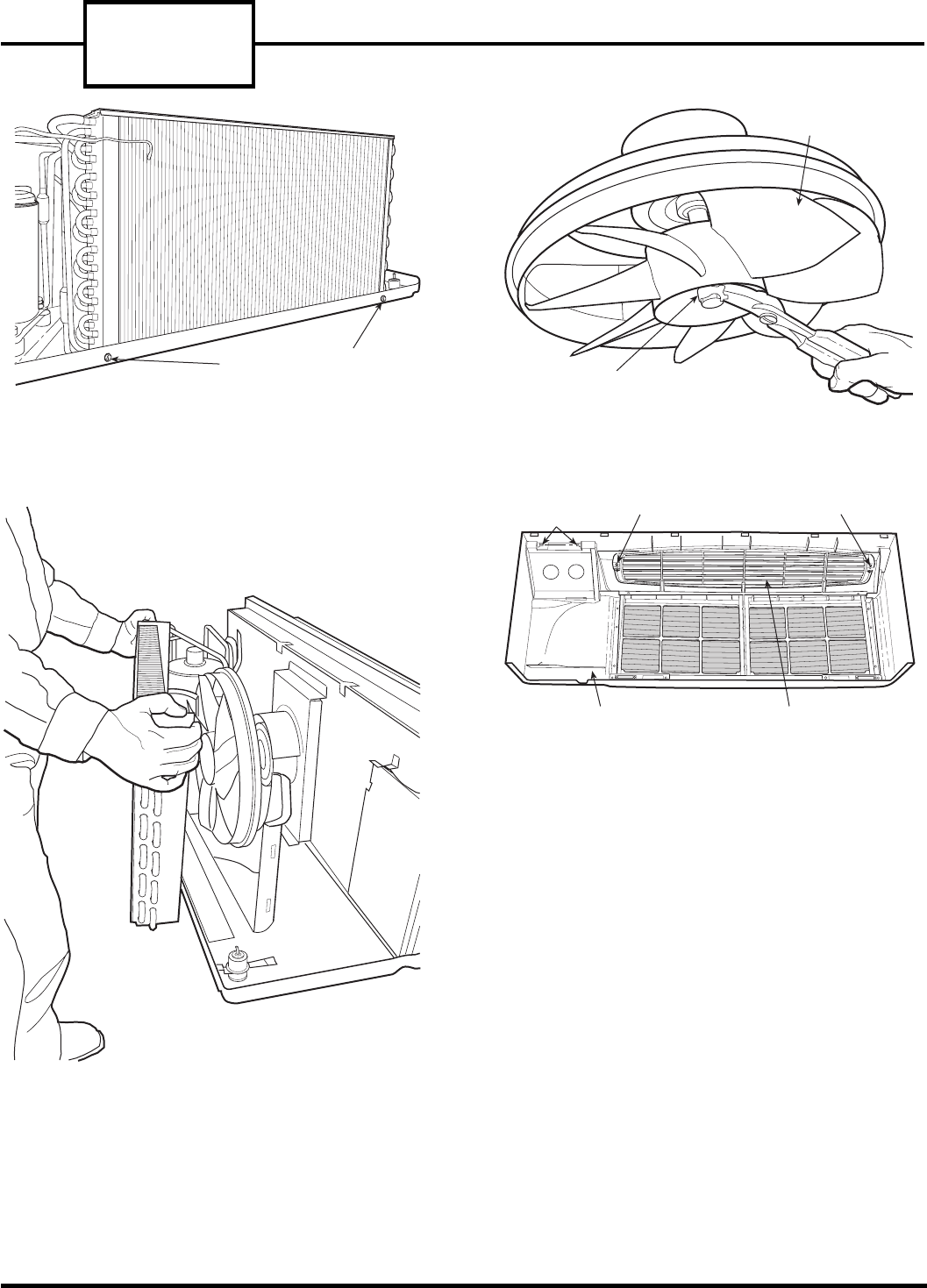
b. Remove 2 outdoor coil tube sheet screws using a
Phillips head screwdriver. See Figure 16.
c. Carefully lift condenser up and away from con-
denser fan. Rest condenser on basepan. See
Figure 17.
d. Using Needle Nose Pliers remove condenser fan
hub clamp. See Figure 18.
e. Pull condenser fan off fan motor shaft.
f. Remove bottom half of condenser orifice.
3. Reassemble by reversing steps above.
■ REMOVE THE AIR DISCHARGE GRILLE
1. Remove the front panel from the unit, reference
Remove Front Panel section.
2. Flip the front panel over to the backside. Remove
the 2 screws on each end of the air discharge grille
and remove grille. See Figure 19.
The grille can be positioned to direct the
discharge air up or out by simply rotating
the grille 180 degrees.
END CAP
LEFT
BRACKET
BRACKET
SCREWS
PLENUM LATERAL DUCT
EXTENSION
WALL
TOP
SCREWS (2)
BRACKET
SCREWS
RIGHT
BRACKET
ATTACHMENT
SCREWS
DISCHARGE
SCREEN
DISCHARGE
DECK
DISCHARGE DECK
HEATER PLATE
ASSEMBLY
FIGURE 8 — PTAC UNIT WITH LATERAL
DUCT ACCESSORY INSTALLED
FIGURE 9 — LOCATION OF ATTACHMENT
SCREWS ON DISCHARGE DECK OF UNIT
FIGURE 10 — ACCESSING HEATER
PLATE ASSEMBLY
FIGURE 11 — REMOVAL OF HEATER
PLATE ASSEMBLY
7
GUSSET
SCREWS
GUSSET
SCREWS
PARTITION GUSSET
CONDENSER
ORIFICE (PLASTIC)
GUSSET
CONDENSER
ORIFICE
CAPTIVE
SCREWS (2)
CAPTIVE
SCREWS (2)
FIGURE 12 — GUSSET REMOVAL
FIGURE 13 — LOCATION OF CAPTIVE SCREWS
ON CONDENSER ORIFICE
FIGURE 14 — PRYING CONDENSER ORIFICE
AWAY FROM TUBE SHEET
FIGURE 15 — REMOVING TOP OF
CONDENSER ORIFICE
52C,P
SERIES
8
REINSTALL FRONT PANEL
1. Grasp the front panel firmly at the center of the
top and bottom of the panel, tilting it forward 5 to
10 degrees from the vertical. See Figure 4.
2. Place the top of the front panel onto the unit,
making sure the top engagement posts have
engaged the slots on the unit. The top edge of the
front panel should be flat against the top of the
unit.
3. Gently lower the front panel onto the chassis,
ensuring the conduit/cord is routed through the
panel notch. Magnetic latches at the bottom of the
front panel will secure the front panel to the unit.
HUB CLAMP
CONDENSER
FAN
SCREW SCREW
DISCHARGE
GRILLE
FRONT PANEL
(BACK VIEW)
CONTROL DOOR
HINGE PINS
FIGURE 18 — REMOVING CONDENSER
FAN HUB CLAMP
FIGURE 19 — LOCATION OF SCREWS ON
DISCHARGE GRILLE
OUTDOOR COIL TUBE
SHEET SCREWS
FIGURE 16 — LOCATION OF OUTDOOR
COIL TUBE SHEET SCREWS
FIGURE 17 — REMOVING OUTDOOR COIL
FROM CONDENSER FAN
9
GENERAL CLEANING
Maintaining proper performance of 52C,P systems
requires conscientious cleaning and care of compo-
nents. See Figure 20. Specific components require
periodic cleaning and/or replacement, including the
following:
COMPONENT CLEANING SCHEDULE
CLEANING AND SAFETY
Before starting to clean a unit, read the instructions
thoroughly and gather the necessary tools for the job.
Review all safety information on unit and in literature.
Indoor Air Filter Monthly
Vent Air Filter Monthly
Indoor Coil Seasonally
Indoor Fan Seasonally
Outdoor Coil Seasonally
Before cleaning, servicing, performing maintenance,
or removing the chassis from the wall sleeve, discon-
nect all power to the unit to avoid the possibility of
electrical shock and personal injury. Only trained
and qualified service personnel should perform
installation and service procedures on these units.
Untrained personnel may perform basic mainte-
nance tasks such as cleaning and replacing filters.
Refer to General Disassembly section of this manual
for proper procedures to disconnect power to 52C,P
units.
Consider the following safety issues before
beginning:
• New and unfamiliar tasks should be performed
under the supervision of an experienced service
technician.
• Personal protective equipment, such as safety
glasses and work gloves, should be used.
• The floor around the work area should be clean and
free of debris.
• The 52C,P unit weighs up to 150 pounds. Use a lift-
ing device or ask for assistance if the unit must be
moved.
• Make sure tools are the correct tools for the job,
and that they are working properly and in good
condition.
FRONT
PANEL
(STANDARD)
EXTERIOR
GRILLE
(ACCESSORY)
CHASSIS
(STANDARD)
WALL SLEEVE
(ACCESSORY)
FIGURE 20 — STANDARD 52C UNIT
52C,P
SERIES
10
TOOLS NEEDED
The following list includes the recommended tools,
devices, and cleaning solutions for use in cleaning the
52C,P unit and components.
MONTHLY CLEANING
■ AIR FILTERS — The indoor and vent air filters
should be cleaned once per month. Filters that are not
cleaned become clogged and will restrict airflow. This
may lead to major component damage. If a filter
becomes torn, has holes, or other damage, replace it
with a new one. Replacement filters are available
through Carrier Finished Goods and Carrier Replace-
ment Component Division.
■ CLEANING THE INDOOR AIR FILTER — Two air
filters are located in the unit’s front panel. To remove
each filter simply grasp each filter handle with both
hands and gently pull the filter up and away from the
unit. See Figure 21.
■ REPLACING THE INDOOR AIR FILTER —
Remove the indoor air filter as detailed in Cleaning
the Indoor Air Filter. If damaged, use a filter replace-
ment with the Carrier Part No. AIR-FILTER-10PK,
available through Carrier Finished Goods and Carrier
Replacement Component Division.
NOTE: Both filters are completely interchangeable.
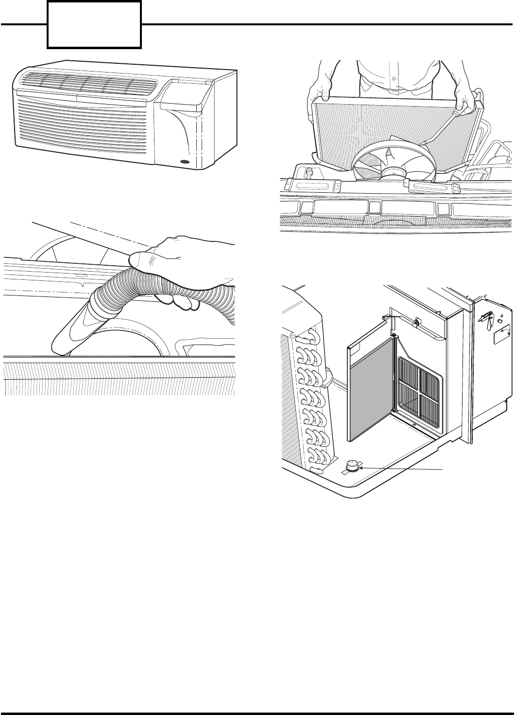
■ CLEANING THE OUTDOOR AIR VENT FILTER
1. Remove the unit chassis from wall sleeve as
described in the General Disassembly section of
this manual. Refer to Remove the Unit from
the Wall Sleeve section.
2. Swing open vent door. The filter is located directly
behind the vent door. See Figure 22.
3. Once the filter is accessed, it may be cleaned using
either a vacuum cleaner, or a soft bristle brush
and a small amount of mild dish detergent. If
detergent is used, remove detergent residue with
a gentle, clean water stream. Allow the filter to
air dry.
■ REPLACING THE OUTDOOR AIR VENT FILTER —
If vent filter requires replacement:
1. Open vent door to access vent filter.
2. Remove vent door from hinges.
3. Using a small flat head screwdriver, pry the filter
from the partition.
4. Replace vent filter using Carrier Part No.
52CQ500144.
5. Reverse Steps 1-3 to reattach vent door.
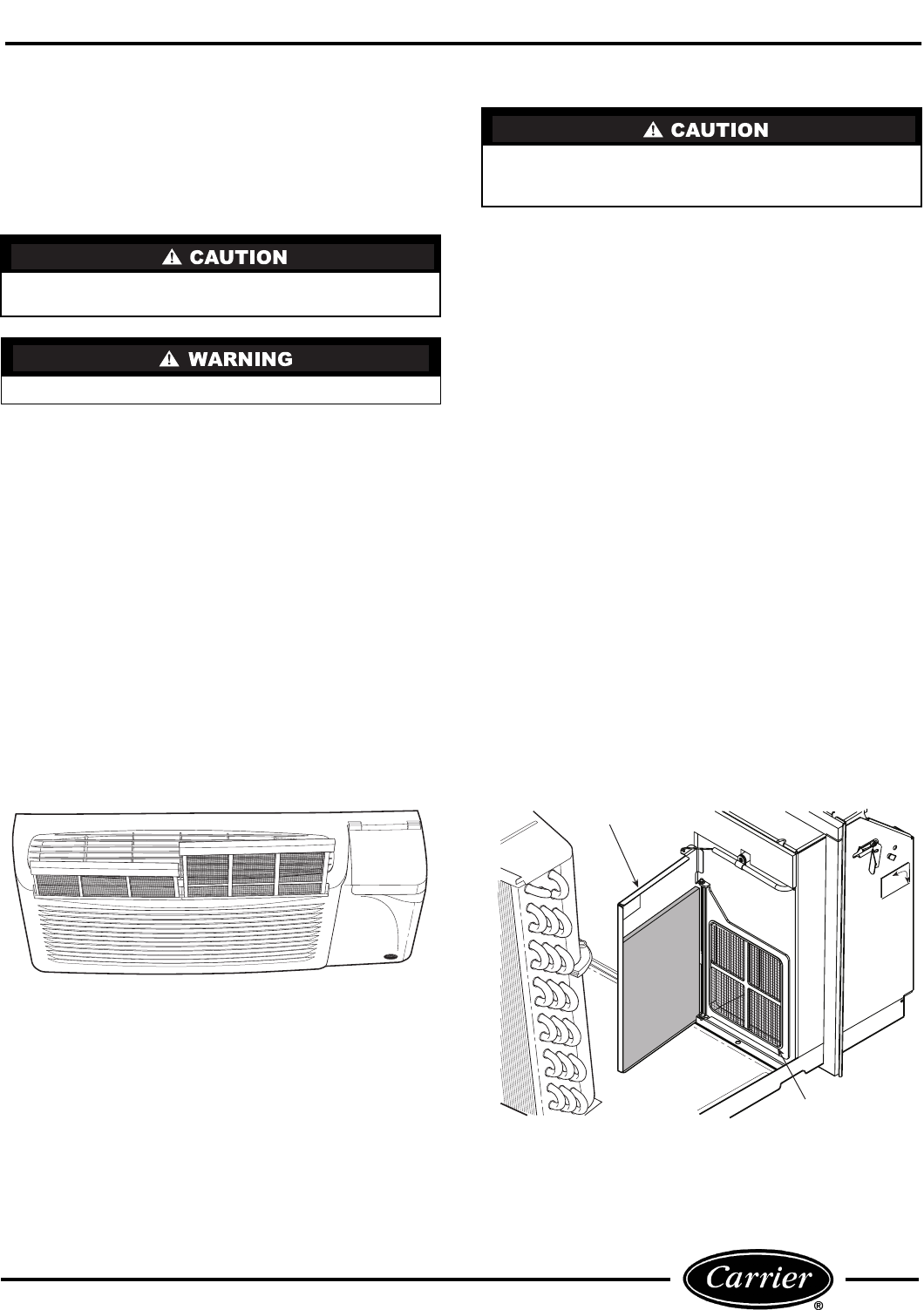
■ CHASSIS
Occasional cleaning of the exterior surfaces of the
PTAC unit optimizes the unit’s appearance and
removes particles that may enter the air system. See
Figure 23. Mild detergents clean and reduce electro-
static charges on the plastic components of the PTAC
unit.
Use a clean cloth or brush to gently wipe exterior sur-
faces. Be careful not to push dirt or other fibers into
the unit’s interior components. Accessible wall sleeve
surfaces should also be wiped clean.
Vacuum Cleaner with Crevice Tool Attachment,
or Soft Plastic Bristle Brush
Mild Household Detergent
Phillips Head Screwdriver
5/16-in. Nut Driver
Flat Head Screw Driver
Needle Nose Pliers, 90° Bend
Lifting Device (or another person for assistance)
Tank Sprayer (Part No. P9021001) or
Trigger Spray Extension Tube (Part No. P9029000)
Compressed Air Tank
Clean Water Supply
Indoor Air Filter Replacement
(Part No. AIR-FILTER-10PK)
Vent Air Filter Replacement (Part No. 52CQ500144)
Condenser Coil Cleaning Solution (Part No. P9020501)
Evaporator Coil Cleaning Solution (Part No. P90221001)
10-in. by 29-in. Piece of Clean Cardboard
3% Solution of Hydrogen Peroxide in Spray Bottle
Clean Cloth
Safety Glasses
Protective Gloves
11
SEASONAL CLEANING
The indoor and outdoor coils should be cleaned at least
once during every season. Refer to ACCESSING
UNIT COMPONENTS section to prepare unit.
■ CLEANING THE INDOOR AND OUTDOOR
COILS
1. Use a vacuum cleaner or soft bristle brush to
remove surface fibers and dirt from the interior
surface of evaporator coil and both surfaces of con-
denser coil. See Figure 24. It is important to apply
the tool in the same direction of the fins, not
against them. Applying the tool against the fins
may cause damage (fin edges may bend over).
2. With a tank sprayer or a trigger spray extension
tube, spray coil cleaning solution evenly across
the coils, making sure coils are thoroughly satu-
rated. See Figure 25. Refer to instructions on the
cleaning solution containers for best results. Do
not use a high-pressure sprayer.
3. Rinse the coils thoroughly with low-velocity, clean
warm water (less than 200 F).
4. Repeat steps 2 and 3 for each coil surface.
5. Drain water and cleaning solution that may have
collected in the basepan during the cleaning pro-
cess by carefully tilting the chassis. This allows
excess water to flow out of the overflow notches.
6. Thoroughly clean the basepan and drain passages
by rinsing with clean water. Be sure all debris is
removed from the drain valve. See Figure 26.
7. Thoroughly clean outdoor fan assembly and all
other mechanical components located in outdoor
coil area. Be sure to remove all dirt and debris.
8. Clean wall sleeve.
■ CLEANING THE INDOOR FAN AND FAN
SCROLL — Dried debris and build-up on the blower
wheel and fan scroll can reduce the efficiency of the
unit.
1. ACCESS AND CLEAN INDOOR FAN AND
FAN SCROLL
a. Reach behind the indoor coil and vacuum any
loose debris from the condensate drain pan, fan
and other areas accessible to the fan scroll,
being careful to avoid damage to the coil fins.
b. Use mild detergent and a damp cloth to remove
stubborn debris from surfaces around scroll and
fan blades.
2. CLEAN HEATER ASSEMBLY — Use com-
pressed air to blow off any dirt or dust that has
accumulated on the heater coils.
NOTE: Do not direct air at the bi-metal discs on
the temperature limiter switches.
Coil fins are sharp and may cut hands. Wear heavy
protective gloves when cleaning coils.
Use only cleaning solutions that meet local codes.
Do not set unit on end to drain water from basepan,
or at any other time. Oil will drain from the com-
pressor sump, which could cause compressor failure.
FIGURE 21 — LOCATION OF
TWO-PIECE INDOOR FILTER
VENT DOOR
OUTDOOR
AIR FILTER
FIGURE 22 — LOCATION OF OUTDOOR AIR
VENT FILTER
52C,P
SERIES
12
DRAIN VALVE
FIGURE 24 — VACUUMING EVAPORATOR
COIL
FIGURE 25 — CLEANING COILS
FIGURE 23 — PTAC EXTERIOR SURFACES
FIGURE 26 — BASEPAN SECTION
13
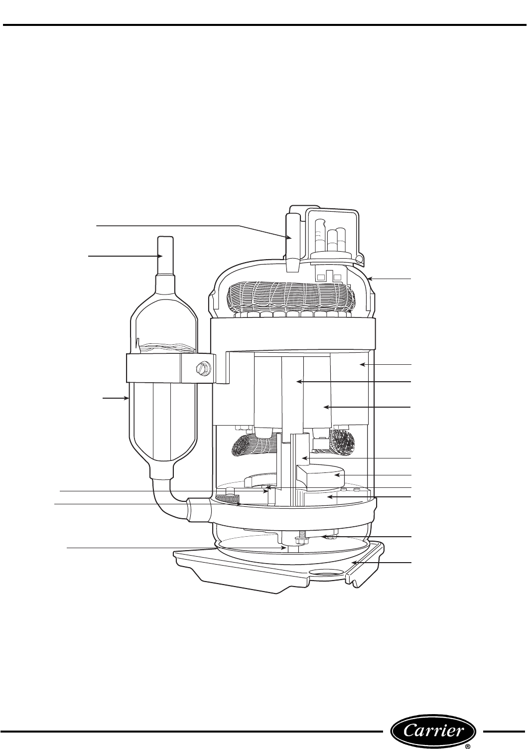
COMPRESSOR
A cutaway view of the rotary compressor with key
components labeled is shown in Figure 27. The motor
stator is rigidly attached to the compressor shell. The
rotor is pressed onto the eccentric shaft, which is sup-
ported by 2 bearings. Both the discharge valve and dis-
charge muffler are attached to the motor bearing. The
pump bearing provides a thrust surface for the shaft
and the rolling piston. Compressed gas is separated
from the suction gas by the vane. Discharge gas pres-
sure and the vane spring keep the vane in contact with
the rolling piston.
DISCHARGE MUFFLER
DISCHARGE VALVE
CYLINDER
PISTON
SUCTION MUFFLER/
ACCUMULATOR
SUCTION INLET
DISCHARGE TUBE
VANE
OIL TUBE
SHELL
STATOR
ECCENTRIC SHAFT
ROTOR
MOTOR BEARING
PUMP BEARING
MOUNTING PLATE
FIGURE 27 — ROTARY COMPRESSOR COMPONENTS
52C,P
SERIES
14
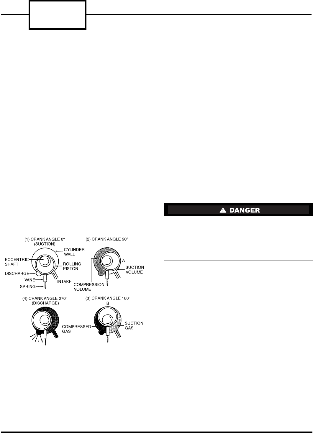
The rotary compression process (Figure 28), starts at
top dead center as shown in (1). Suction gas flows
through the suction inlet and into the cylinder area.
As the shaft rotates through 90 degrees, the rolling
piston moves to position A as shown in (2). The suction
volume is now the area defined by point A and the tip
of the vane. Gas in the remaining volume has been
compressed above suction pressure. After another
90 degrees of shaft rotation, the rolling piston has
moved to position B as shown in (3). Both the com-
pressed gas and suction gas volumes are now equal.
Another 90 degrees of shaft rotation is shown in (4).
Compressed gas has reached a pressure sufficient to
open the discharge valve, and flows from the cylinder
into the compressor shell. After another 90 degrees of
shaft rotation, the entire process begins again. Contin-
uous suction and discharge allows for a smooth com-
pression process.
The rolling piston is not in actual contact with the cyl-
inder wall, vane, or bearing faces. Hydrodynamic seal-
ing prevents leakage from the compressed gas volume
to the suction volume via these paths. Precise control
of machining tolerances, surfaces, finishes, and assem-
bly clearances is critical to achieve high efficiency per-
formance. In addition, the line contact between the
vane tip and the rolling piston requires careful selec-
tion and control of materials to provide wear resis-
tance and reliable long-term operation.
COMPRESSOR TROUBLESHOOTING
Refer to Figure 29 for a basic compressor troubleshoot-
ing chart.
BASIC HERMETIC COMPRESSOR
ELECTRICAL MEASUREMENTS
There are 2 basic electrical tests for hermetic compres-
sors that will determine the electrical state of the
motor. The first test requires checking the electrical
resistance of each of the electrical motor windings. The
second test requires checking the electrical resistance
of each of the electrical motor windings to ground.
These tests may be accomplished by performing the
following steps:
1. DISCONNECT ALL POWER TO THE UNIT.
2. Remove the unit chassis from the sleeve as
detailed in the UNIT DISASSEMBLY section.
3. Open the control box as detailed in the UNIT
DISASSEMBLY section, then locate, label, and
remove the 3 compressor wires from the following
locations: the RUN wire (BLACK) from the capac-
itor, the START wire (BLUE) from the capacitor.
The third wire, COMMON wire (YELLOW) may
be connected to one of the following locations: for
PC units the wire is on the indoor thermostat,
for CE, PE Remote Control Units the wire is
on the RC Control Board, for all other CE, PE
Units the wire is located on the rotary selector
switch. For ALL CQ, PQ Units the wire is on the
outdoor frost thermostat.
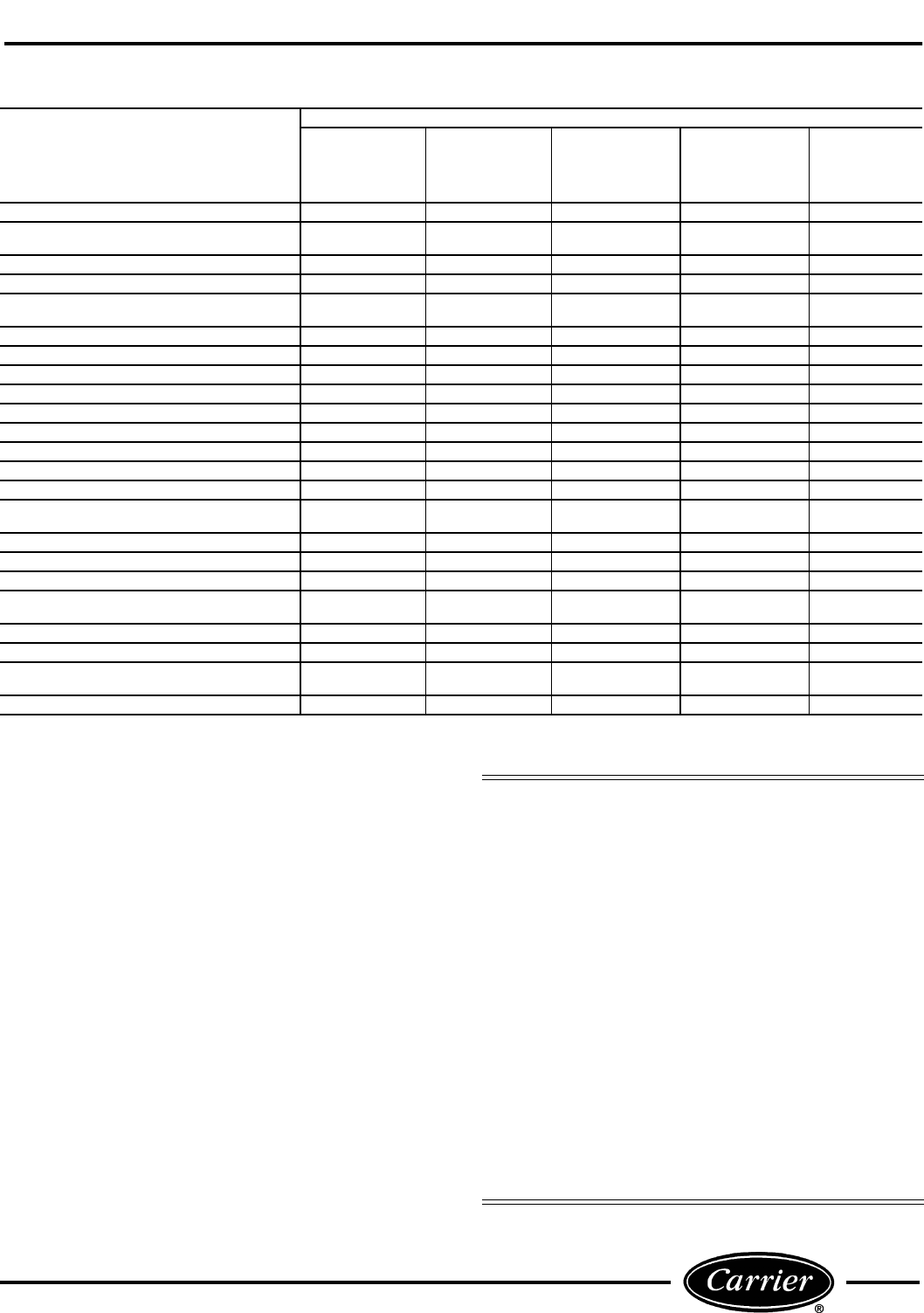
4. Perform a shorted/open windings test to measure
the resistance between the windings of the com-
pressor motor. Use a volt-ohmmeter set to the
lowest ohm reading level then read and record the
resistance between the RUN and START, START
and COMMON, and RUN and COMMON wires.
See Figure 30. The typical resistance readings will
be about 4, 3, and 1 ohms respectively. The
smaller values should add to equal the larger
value. If this is not true then the compressor is
likely shorted winding to winding.
NOTE: The rotary compressor has the compressor
overload located under the terminal cover. If the over-
load is open it can show ohm readings that are infinite.
The unit should be off for at least an hour to give this
overload time to reset if it is open.
For compressors that are known to be dam-
aged: Remove refrigerant prior to disconnecting
compressor wires. Damaged hermetic compressor
terminals may become loose and eject from the com-
pressor. Wear safety glasses and keep your face
away from the area above the terminals when
removing compressor wires.
FIGURE 28 — ROTARY COMPRESSOR
COMPRESSION PROCESS
15
FIGURE 29 — BASIC COMPRESSOR TROUBLESHOOTING GUIDE
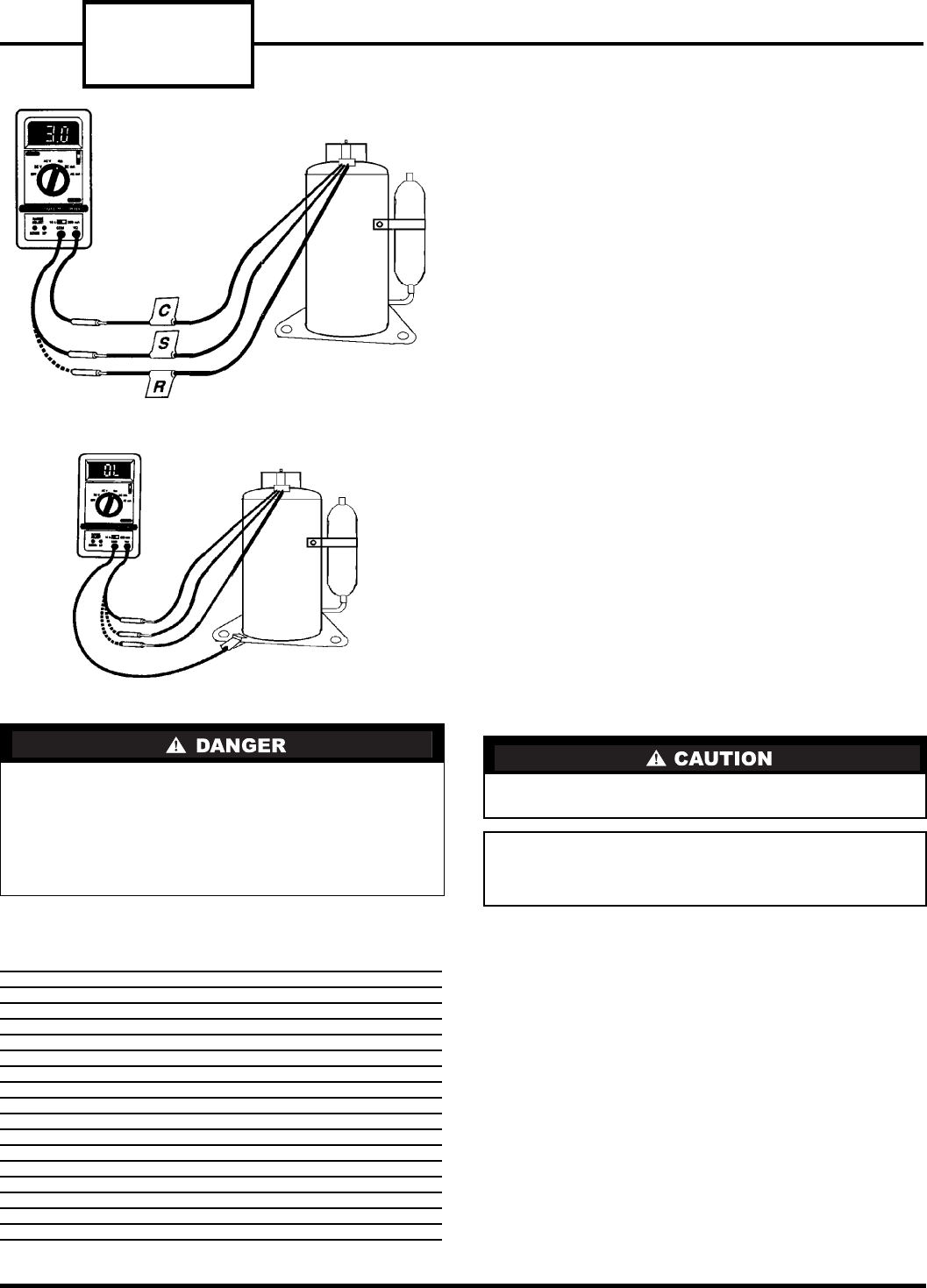
5. Next, perform a grounded windings test to test
the resistance individually of each wire to the
shell of the compressor. The paint on the compres-
sor can prevent good contact between the probe
and the metal. The paint should be removed from
a small section of the shell of the compressor to
ensure good contact by the meter probe. The volt-
ohmmeter should be set to at least the 100X ohm
level. The measured resistance between each wire
and ground should be infinite or O.L. on the
readout. If there is measurable resistance one of
the windings is likely shorted to ground. See
Figure 31.
6. A compressor that has a winding to winding short
or a winding to compressor shell short is electri-
cally failed and needs to be replaced. See the
Compressor Replacement section for details.
COMPRESSOR REPLACEMENT
Before working on the compressor, read the instruc-
tions thoroughly and gather the necessary tools for the
job. Review all safety information on unit and in liter-
ature. Always turn off all power to unit to avoid the
possibility of electrical shock.
POSSIBLE CAUSE
SYMPTOM
Compressor
Starts and
Runs But
Cycles On the
Overload
Compressor
Starts After
Cycling the
Overload
Several Times
Compressor
Will Not
Start. It Hums
and Cycles On
the Overload
Compressor
Will Not Start
and Makes No
Noise
Compressor
Cycles Off
(Not On
Overload)
COILS/FILTERS DIRTY OR PLUGGED X
AIR OR NONCONDENSABLE GASES
IN SYSTEM XX
SYSTEM REFRIGERANT OVERCHARGED X X
DISCHARGE LINE RESTRICTED XX
CAPILLARY TUBE OR STRAINER
RESTRICTED OR PLUGGED XX X
FAN BLADE OR MOTOR DEFECTIVE X X
FAN BLADE OR BLOWER WHEEL STUCK X X
SYSTEM REFRIGERANT UNDERCHARGED X X
EVAPORATOR AIRFLOW RECIRCULATION X
UNIT OVERSIZED FOR APPLICATION X
COMPRESSOR REQUIRES START ASSIST XX
NO POWER TO UNIT X
LOW VOLTAGE TO UNIT XX X X
OVERLOAD PROTECTOR OPEN X
OVERLOAD PROTECTOR INCORRECT
OR DEFECTIVE XXX
CAPACITOR INCORRECT OR DEFECTIVE XX X X
THERMOSTAT CONTACTS ARE OPEN X
THERMOSTAT IS SET TOO HIGH OR LOW X
SELECTOR SWITCH IS OPEN
OR DEFECTIVE X
WIRING IS INCORRECT OR DEFECTIVE XXXX
SYSTEM PRESSURES NOT EQUALIZED XX X
COMPRESSOR MOTOR OR
MECHANISM DEFECTIVE XX X XX
COMPRESSOR GROUNDED X
Consider the following safety issues before
beginning:
• New and unfamiliar tasks should be performed
under the supervision of an experienced service
technician.
• Personal protective equipment, such as work gloves
and safety glasses, should be worn.
• The floor around the work area should be clean and
free of debris.
• Make sure tools are the correct tools for the job and
that they are working properly and in good condition.
• Never replace a blown fuse without correcting the
cause of the original failure. If thermally operated
circuit breakers or overloads are tripping, make
sure the trip is not due to excessively high tempera-
tures or loose connections.
• When brazing suction and discharge lines, cool the
lines with a damp, clean cloth to prevent injury.
• Oil may be present in the compressor accumulator
and interconnecting tubing. Use caution when
removing tubing.
52C,P
SERIES
16
■ TOOLS NEEDED — The following list includes the
recommended tools and devices for removing and
replacing the compressor.
■ REMOVING THE COMPRESSOR — Follow the
steps below to remove the compressor:
1. Disconnect all power to unit.
2. Remove unit from wall sleeve as detailed in the
UNIT DISASSEMBLY section. The unit weighs
up to 150 pounds. Seek assistance or use a lifting
device when removing unit from wall sleeve.
3. If the unit is a heat pump: Disconnect the wire
plug on the reversing valve solenoid and carefully
remove the outdoor thermostat capillary from the
outdoor coil. See Figure 32.
4. Attach the piercing valve to the suction side pro-
cess tube below the crimps. Attach Carrier
TOTALTEST® kit (Part No. TT1-001), to the
piercing valve to verify acidity of the system. After
verifying the system acidity, remove the refriger-
ant using a certified refrigerant recovery system.
5. When all the refrigerant has been recovered,
remove the terminal cover from the compressor
with a nut driver. Disconnect the 3 wires from the
compressor and label the location of each. Once
the wires are labeled, replace the terminal cover
to protect the compressor terminals.
6. Remove the air system components by following
the procedure detailed in the ACCESSING UNIT
COMPONENTS section.
7. Remove the piercing valve and cut the crimped
portion of both process tubes off with a small tub-
ing cutter. Braze an access valve on each process
tube. Using a torch, disconnect the suction and
discharge tubes from the compressor connections.
8. Remove the compressor mounting bolts, and
remove the compressor.
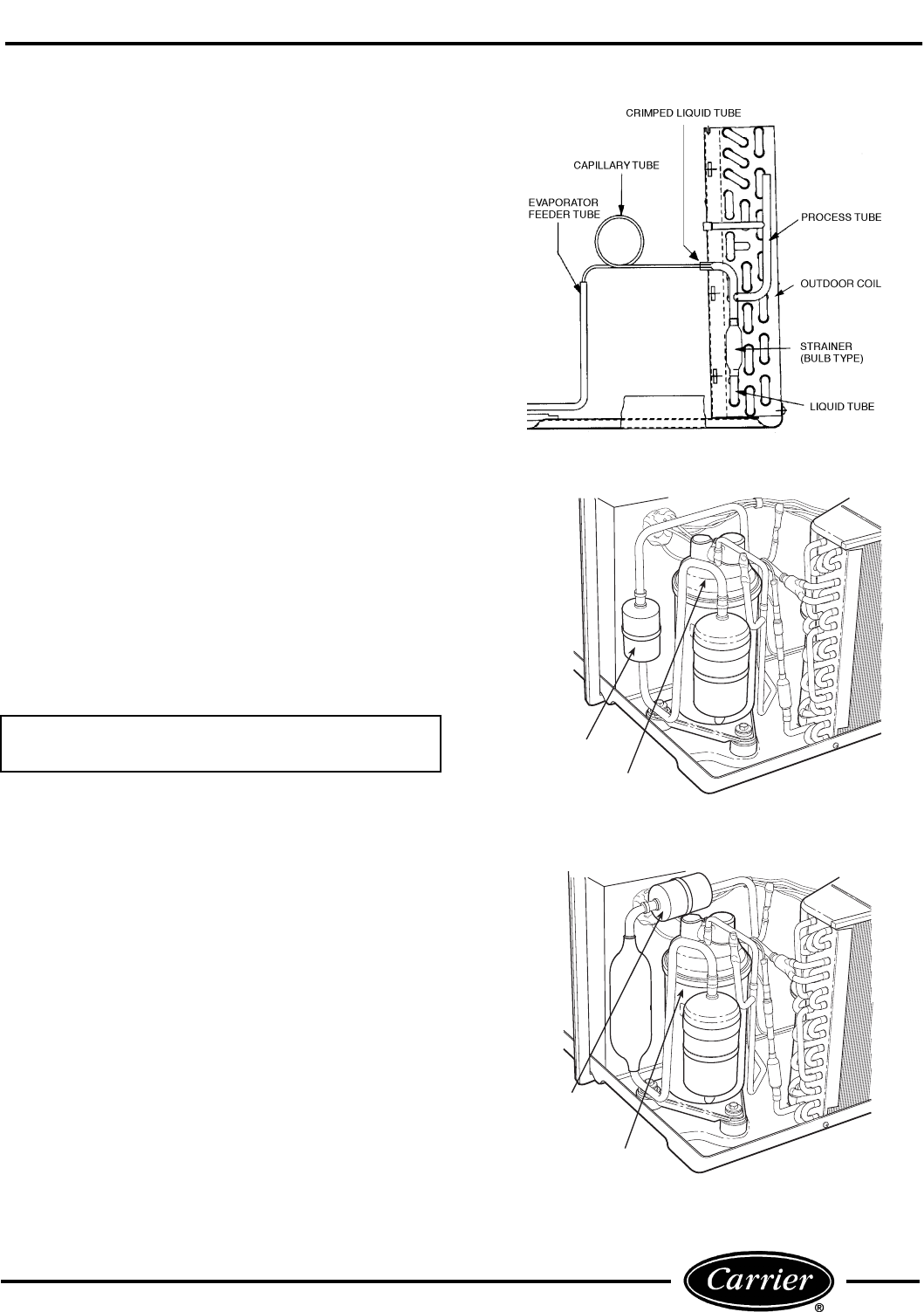
9. For all units: Remove and replace the strainer
and capillary tubes from the system. See Figure 32
for strainer and capillary tube location.
10. For Heat/Cool Units: Use an in-line filter drier
(P/N P504-80845). The filter drier can be installed
in any location in suction line. See Figure 33A for
general installation location.
For Heat Pump Units: Use an in-line filter drier
(P/N P504-80845) and install between the
reversing valve and the compressor accumu-
lator. There are several suction tube configura-
tions and the in-line filter drier will be field piped
and brazed into the suction tube for your unit. See
Figure 33B for a general installation location.
11. Remove the grommets from the existing compres-
sor and install them onto the new compressor.
For compressors that are known to be dam-
aged: Remove refrigerant prior to disconnecting
compressor wires. Damaged hermetic compressor
terminals may become loose and eject from the com-
pressor. Wear safety glasses and keep your face
away from the area above the terminals when
removing compressor wires.
1/2-in. and 3/8-in. Tube Benders
1/2-in. Nut Driver
5/16-in. Nut Driver
Flat Head Screwdriver
Piercing Valve
2 Parker Access Valves (Part No. AVUSE-5)
Pinch Off Tool
Filter Drier — All Units (Part No. P504-80845)
Carrier TOTALTEST Kit (Part No. TT1-001)
Totalclaim System
Charging Cylinder or an Electronic Scale
Refrigerant-22
Tubing Cutter
Torch
Nitrogen Cylinder with Regulator
Strainers
Capillary Tubes
The compressor may still be hot from the brazing
process.
IMPORTANT: Any time the compressor is
replaced, the strainer and capillary tubes must
be removed and replaced also.
FIGURE 30 — SHORTED/OPEN WINDINGS TEST
FIGURE 31 — GROUNDED WINDINGS TEST
17
12. Install the new compressor and the new capillary
assembly (the correct capillary and strainer may
be obtained from Carrier RCD), into the unit.
13. Leak check the unit with 150 psi of nitrogen
pressure.
14. For 52C,P units, the system should be evacuated
from the high side to the low side to a minimum
of 200 microns of mercury. This evacuation
removes residual moisture from the system prior
to charging.
15. For Heat Pump Units: Recharge unit to the
nameplate refrigerant charge using a charging
cylinder.
16. Pinch off each access valve on the process tubes,
in 2 places, using a pinch off tool such as Imperial
tool #105-FF or Robinair Tool #12294. Release any
refrigerant pressure trapped in the access valve
by depressing the valve core, then confirm that no
R-22 is leaking past the pinch off tool location. Cut
the access valve stem of the process tube above
the top crimp and braze the top of each process
tube to ensure the system is sealed, (leave the
pinch off tool in place until after the brazing pro-
cess is complete).
17. Reassemble the unit by reversing steps 1-9.
18. Connect the compressor wires and energize the
unit to verify operation.
■ REFRIGERANT CHARGING — Every mechanical
refrigeration system that is opened for servicing must
be accurately charged before it is returned to service.
Run the compressor ONLY after charging the system
with refrigerant.
It is important to remember that recovered and/or
recycled refrigerant may only be recharged into the
system from which it was initially recovered, or
another one owned by the same customer. Charge
level is important. Charge units only as recommended
by manufacturer.
IMPORTANT: The compressor should never be
operated without refrigerant!
IN-LINE
FILTER DRIER
COMPRESSOR
IN-LINE
FILTER DRIER
COMPRESSOR
FIGURE 32 — STRAINER AND
CAPILLARY TUBE LOCATION
FIGURE 33A — IN-LINE FILTER DRIER —
GENERAL INSTALLATION LOCATION
FOR HEAT/COOL UNIT
FIGURE 33B — IN-LINE FILTER DRIER —
GENERAL INSTALLATION LOCATION
FOR HEAT PUMP UNIT
52C,P
SERIES
18
HEATERS
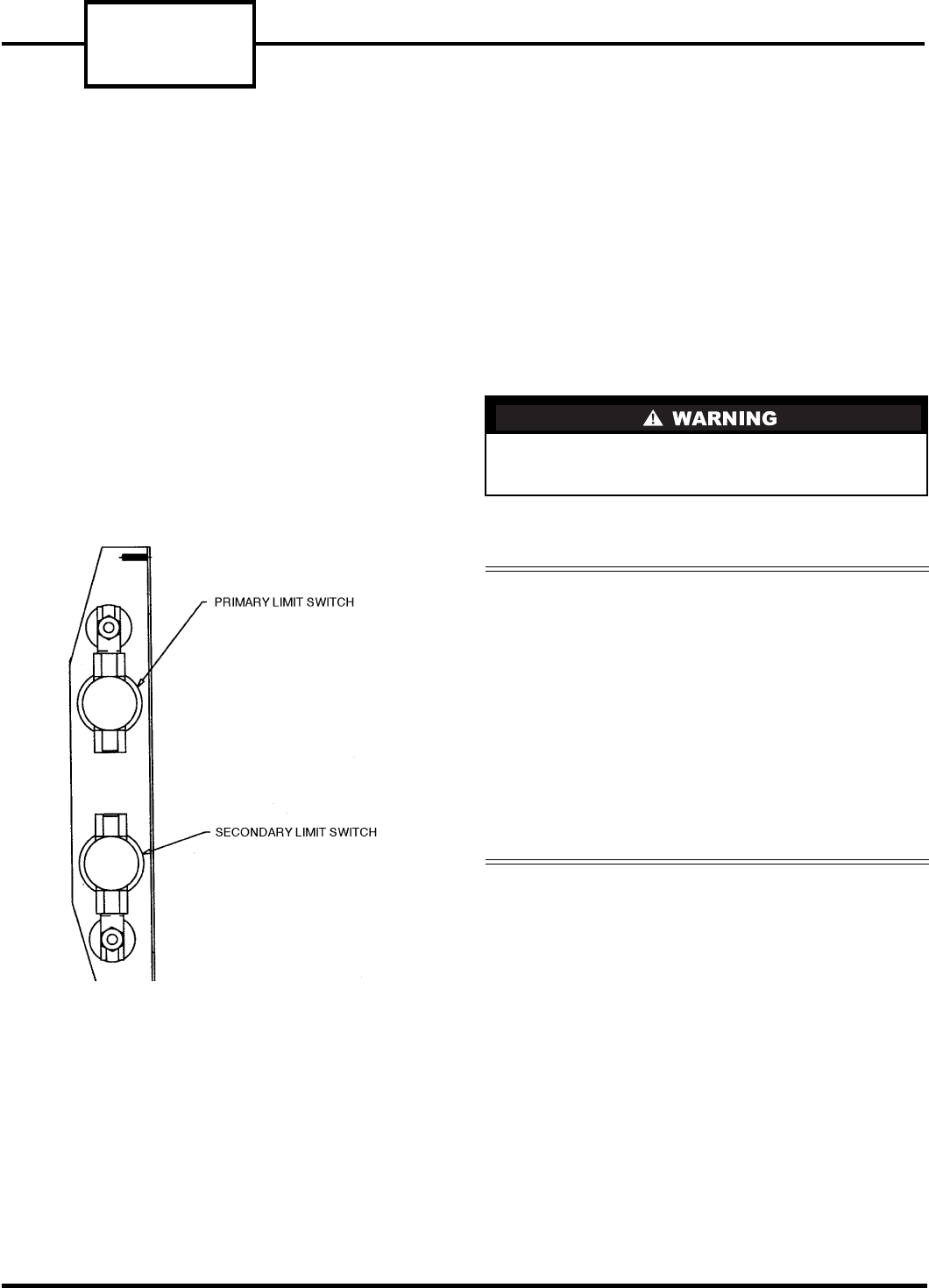
The heater in 52C,P units is located directly behind
the evaporator coil. The heater assembly includes the
heater (2.3 kW, 3.4 kW or 5 kW), a primary limit
switch, and a secondary limit switch. See Figure 34.
The primary and secondary limit switches are safety
switches that regulate heater operation. The primary
limit switch disables current to the heater when the
temperature exceeds the setting on the switch.
For example, a 3.4 kW heater may have a primary
limit switch setting of 150 F. If the temperature at the
switch exceeds 150 F, the primary limit switch will
electrically open and shut off power to the heater.
Once the temperature drops below 110 F, the primary
limit switch will automatically reset.
The secondary limit switch works in the same manner
as the primary limit switch, except it is a one time
switch and has a slightly higher temperature setting.
Once this switch is thermally opened, it must be
replaced. Together the primary and secondary
switches help maintain safe temperature limits for
unit operation.
COMMON CAUSES OF
HEATER FAILURE
Heater failure may result from broken heater coils,
primary limit switch failure, or an open secondary
limit switch. These conditions are generally caused by
low or no airflow.
HEATER REMOVAL
Before working on the heater, read the instructions
thoroughly and gather the necessary tools for the job.
Review all safety information on the unit and in the
product literature.
The manufacturer reserves the right to discontinue, or
change at any time, specifications or designs without
notice and without incurring obligations.
Before performing any cleaning, servicing, or main-
tenance to the unit, Disconnect All Power to avoid
the possibility of electric shock and personal injury.
Consider the following safety issues:
• Prior to performing any service or maintenance on
electrical equipment you must Disconnect All
Power.
• New and unfamiliar tasks should be performed
under the supervision of an experienced service
technician.
• Personal protective equipment, such as safety
glasses and work gloves, should be worn.
• The floor around the work area should be clean and
free of debris.
• Make sure tools are the correct tools for the job,
and that they are working properly and in good
condition.
FIGURE 34 — LIMIT SWITCH LOCATION
19
■ TOOLS NEEDED — The following list includes rec-
ommended tools and devices for working on the heater
section of 52C,P units.
Perform the following steps to remove the Heater
Assembly.
1. DISCONNECT ALL POWER TO UNIT.
2. Remove heater by following instructions in
ACCESSING UNIT COMPONENTS section.
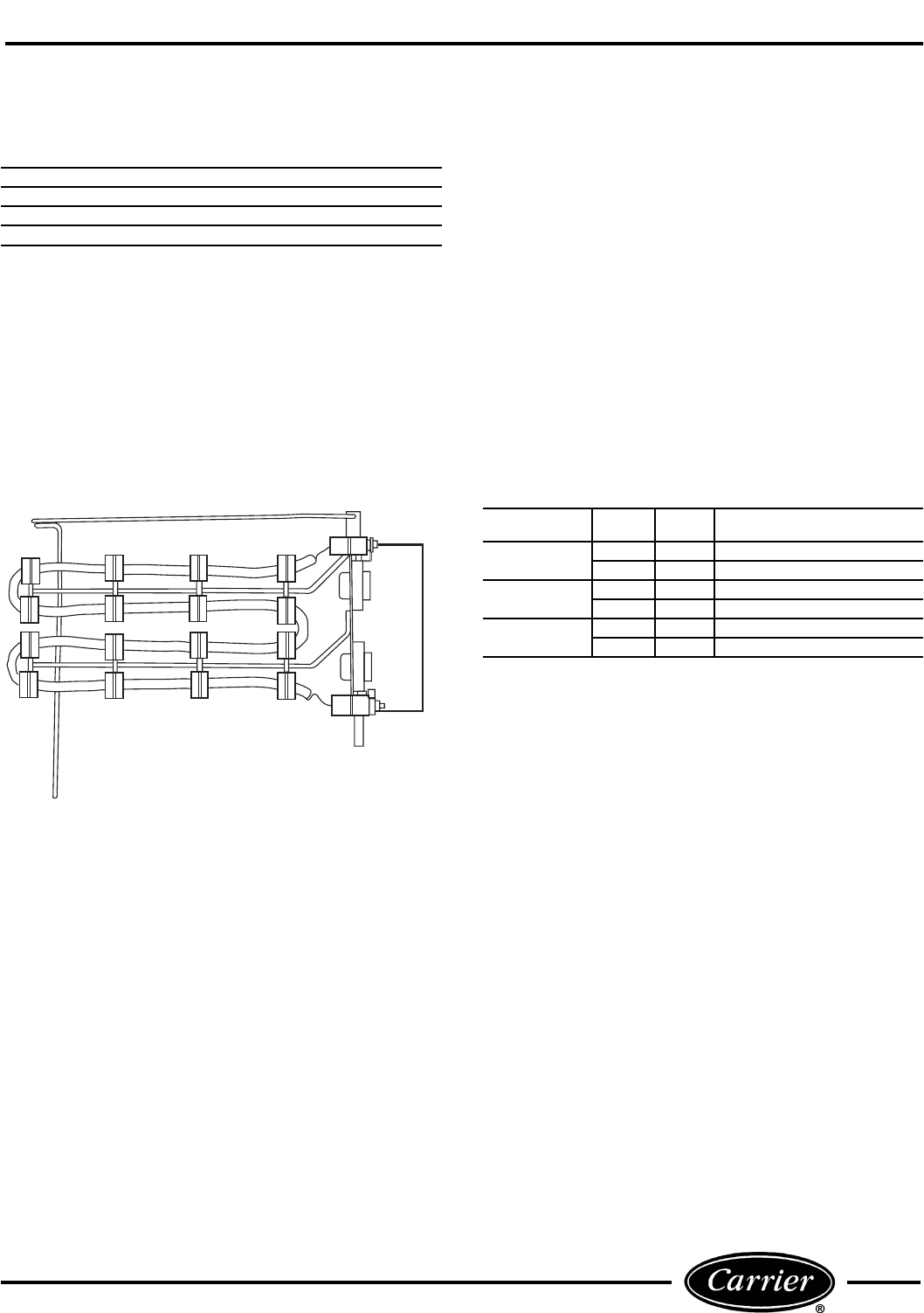
After the heater is removed, examine the heater
as follows to determine if it is operational:
Perform a visual inspection. The heater coil should be
free of breaks. If there are any breaks in the coil,
replacement of the heater assembly is necessary. See
Figure 35.
Coil resistance must also be checked to verify the
heater is operating correctly. The resistance of the
heater coils must meet approximate levels for the
heater to perform at its optimum efficiency. See
Figure 36 for approximate resistance for heaters at
75 F. Before checking the heater coil resistance, be
sure all power to unit is off.
To check resistance, set the volt-ohmmeter selector
switch to the lowest ohms value. Next connect the volt-
ohmmeter leads to each side of the heater coil at the
studs that hold the limit switches in place. Incorrect
readings can be obtained if the wires are not removed
from the limit switches on the heater assembly. If the
resistive reading is infinite or zero, the heater is failed
and replacement is necessary. Reinstall the heater
assembly.
FIGURE 36 — ACCEPTABLE HEATER
RESISTANCE VALUES
Phillips Head Screw Driver
Needle Nose Pliers
Volt-ohmmeter
Nut Driver 5/16-in.
HEATER SIZE WATTS VOLTS ACCEPTABLE RESISTANCE
(Ohms)
2.3 kW 2300 230 20-23
2300 265 28-31
3.4 kW 3400 230 13-16
3400 265 19-21
5.0 kW 5000 230 9-11
5000 265 13-15
FIGURE 35 — HEATER COIL (Removed)
52C,P
SERIES
20
OPERATING CONTROLS
UNIT-MOUNTED CONTROLS
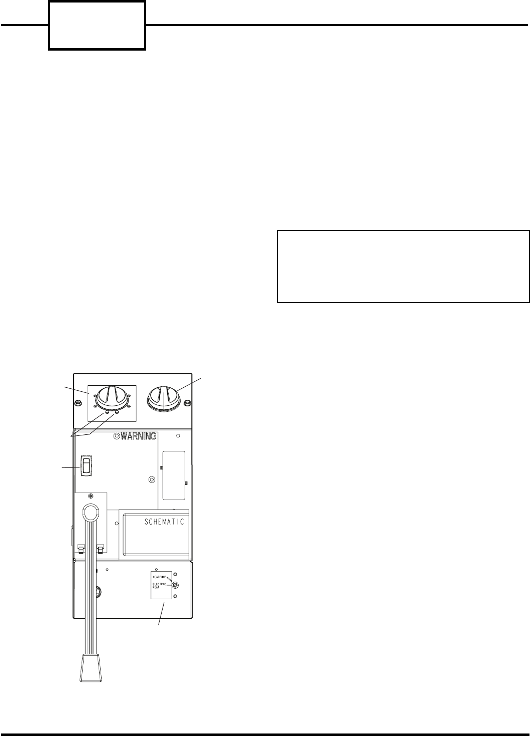
The controls and components used in the 52C,P cool-
ing only or heat/cool units are as follows: the selec-
tor switch, the indoor thermostat, the dual capacitor,
the temperature limiter, the vent lever, and the fan
cycle switch. See Figure 37.
The selector switch is used to determine the mode of
operation: heat, cool, fan, or off. The indoor thermostat
controls the room ambient temperature and cycles the
heater or the compressor based on the selector switch
setting. The dual capacitor aids in the start-up of the
compressor and the fan motor. The temperature limiter
is integrated into the control box top cover located
under front panel. It is a mechanical device that
restricts the amount of rotation of the thermostat. The
temperature limiter device may be adjusted by moving
the plastic temperature selector tabs to another temper-
ature location on the control box. The vent lever is
located on the front left side of the chassis. It is a slide
mechanism that opens and closes the vent door. The
vent control may be accessed by removing the front
panel of the unit. The fan cycle switch is used to provide
2 options of fan control. The first option, CON, causes
the fan to run continuously. The second option, CYC,
causes the fan to cycle on with the compressor or elec-
tric heater and off when the thermostat is satisfied.
The 52C,P heat pump unit contains all the compo-
nents of the heat/cool and cooling only unit, and the
following additional ones: the outdoor frost thermostat
and the reversing valve. The outdoor frost thermostat
prevents operation of the unit in the heat pump mode
when the outdoor coil temperature drops below 20 F,
or at about 35 F outdoor ambient temperature. The
unit automatically engages the electric heat strip and
disables the compressor under these conditions.
The outdoor frost thermostat has a manual override to
place the unit in electric heat mode operation only. The
override switch is located behind the front panel on
the front side of the unit control box door.
The reversing valve allows for operation in reverse cycle
heat pump mode. The valve is located in the piping sys-
tem and is controlled by the reversing valve solenoid
coil. The coil is energized only during the heating mode.
IMPORTANT: Placing the override switch to elec-
tric heat mode operation will disable the compres-
sor for ALL heating or cooling operations (for all
units except RC units). Placing the override switch
to electric heat mode operation on RC units will
only disable the compressor in heating mode.
TEMPERATURE
LIMITER
FAN CYCLE
SWITCH
OUTDOOR FROST
THERMOSTAT
(HEAT PUMP
UNITS ONLY)
80
85
90 60
65
70
75
CON
CYC
SELECT0R
SWITCH
INDOOR
THERMOSTAT
FIGURE 37 — 52C,P OPERATING CONTROLS
21
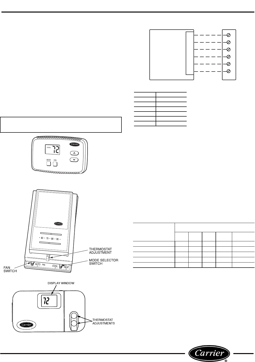
WALL-MOUNTED THERMOSTAT
CONTROLS
For 52C,P wall thermostat control (RC, RP)
units, all controls are located on the wall-mounted
thermostat except the vent lever and outdoor thermo-
stat. Remote control is a factory or field-installed
option. There are 3 styles of thermostats qualified for
use with 52C,P series Remote Control units. See Fig-
ures 38-40. On remote control units, the fan cycle func-
tion is located on the wall thermostat. The rocker
switch on the control box door is used to set fan speed
to high or low. Factory default is low speed.
See Figures 41-43 for thermostat wiring.
A field conversion kit is available to convert an AA
model (standard unit-mounted controls) to an RC
model (wall-mounted controls).
REMOTE THERMOSTAT
TROUBLESHOOTING
Thermostat display is blank:
Check to make sure there is 24 VAC to the thermostat
(measure across terminals R and C at the thermostat).
If there is 24 VAC at the thermostat, check connec-
tions at the thermostat terminal block. If connections
are good and there is 24 VAC with no display, the ther-
mostat should be replaced.
Thermostat display is working but unit is not
heating or cooling:
At the RC terminal block on the unit, measure the con-
trol inputs coming from the thermostat. (Place one of
the meter leads on C and use the other to check the
voltage at each of the terminals.)
*24 VAC supplied if thermostat is in 2nd stage heating demand (large
difference between room temperature and setpoint).
NOTE: For heat pump units, the Outdoor Frost Thermostat (OFT) will
determine, based on outdoor temperature, whether to bring on the com-
pressor or electric heat in the Heating mode.
FIGURE 42 — THERMOSTAT TROUBLESHOOTING
If the inputs are not correct, then the thermostat is not
making a call for the mode requested. This could be
because the thermostat is in a unit protection mode,
not set up properly, miswired, has a broken wire, or it
may have failed.
IMPORTANT: No conversion kit is available to
convert from an RC model back to an AA model.
MODE
TERMINAL
METER READINGS (VAC)
RGY W O (For
HP Only)
Fan Only 24 24 0 0 0
Cooling 24 24 24 0 24
Heating
Heat Pump Unit 24 24 24 0/24* 0
Heat/Cool Unit 24 24 0 24 0
FIGURE 38 — NON-PROGRAMMABLE
THERMOSTAT
FIGURE 39 — MANUAL THERMOSTAT
FIGURE 40 — PROGRAMMABLE THERMOSTAT
TYPICAL
WALL
THERMOSTAT
R
G
Y
W
O
C
TERMINAL
BLOCK
R
G
Y
W
O
C
FIGURE 41 — WIRING CONNECTIONS
TERMINAL DESIGNATION
R24 VAC
GFan
YCompressor
WElectric Heat
OReversing Valve
CCommon
NOTES:
1. Use terminal “O” for heat pump con-
nection only.
2. See table at left for terminal descriptions.
3. Common wire “C” is typically used only
for digital thermostats.
4. Power stealing is NOT allowed. There
must always be a hard common connec-
tion between unit and digital thermostat.
52C,P
SERIES
22
R
Y
W
G
O
C
R
Y
W
G
O
C
R
Y
W
G
O
C
R
Y
W
G
O
C
R
Y
W
G
O
C
T’STAT
MASTER
PTAC
UNIT 1
UNIT 2
UNIT 3
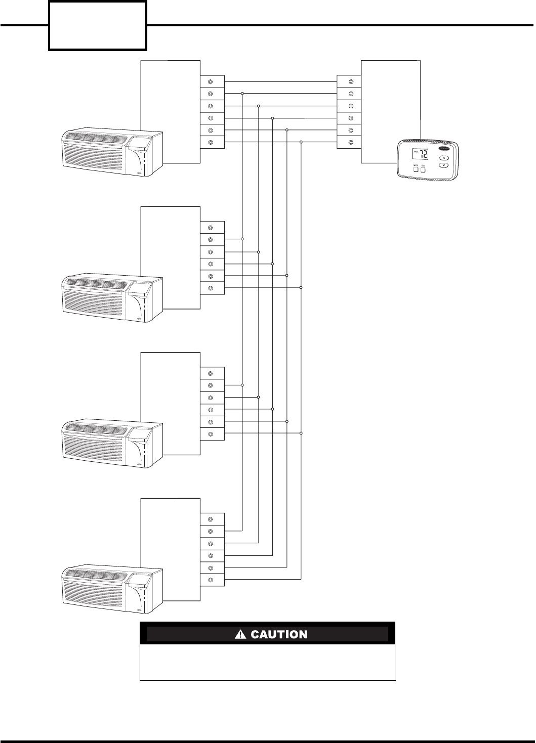
FIGURE 43 — TYPICAL WIRING FOR MULTIPLE 52C PTAC UNITS CONNECTED
TO ONE WALL THERMOSTAT
All units must be connected to same ground source.
To accomplish this, be sure to connect all units back
to the same breaker box.
NOTES:
1. Do not daisy chain R (24 VAC).
2. Maximum of 4 PTAC units can be connected
to one single wall thermostat.
23
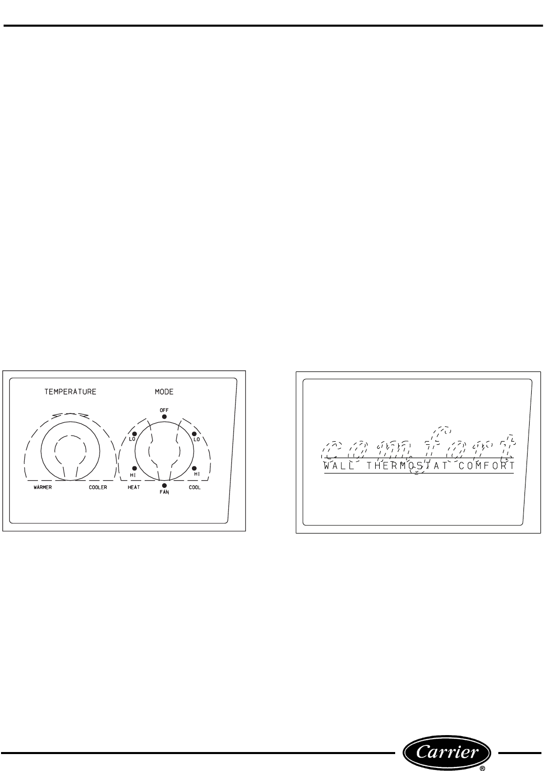
DESCRIPTION OF SELECTOR SWITCH
SETTINGS (Figure 44)
■ OFF MODE — The OFF position terminates unit
operation.
■ FAN ONLY MODE — Use fan only position for air
circulation without heating or cooling. Fan runs at
high speed.
■ HIGH HEAT OR HIGH COOL MODE — Position
selector and temperature control knobs to desired com-
fort level. This function provides maximum heating or
cooling, and is recommended to raise or lower the room
temperature quickly.
■ LOW HEAT OR LOW COOL MODE — Position
selector and temperature control knobs to desired com-
fort level. This function provides minimum heating
or cooling with maximum dehumidification during
cooling. This setting also allows for very quiet fan
operation.
■ FINDING TEMPERATURE SETTING FOR COM-
FORT LEVEL — Set temperature knob in the middle.
Select High Heat, Low Heat or Cool position and allow
unit to run for 15 to 30 minutes. If room is not comfort-
able, turn knob setting slowly to change setting. When
room is comfortable, keep control knob at that
position.
NON-USER ADJUSTABLE CONTROLS
■ OUTSIDE OR VENT AIR — Slide the vent lever to
the fully open position for outside air or fully closed
position for vented air.
■ FAN CYCLE — The fan cycle switch allows the fan
to operate in 2 modes:
CON — Fan runs continuously, circulating air even
when the temperature setting has been satisfied. This
helps to maintain the room temperature closer to the
thermostat setting.
CYC —Fan cycles on and off with the compressor
during heating or cooling. Fan stops when the temper-
ature setting is satisfied. This results in longer unit
off-time and slightly larger variations in room temper-
ature and humidity.
■ OUTDOOR THERMOSTAT (52CQ, PQ Units Only)
— The outdoor thermostat has 2 operating modes. The
heat pump mode (selector screw set fully clockwise),
allows the unit to operate normally in the reverse cycle
mode. The electric heat mode (selector screw set fully
counterclockwise), disables all compressor operating
modes, both heating and cooling for units with
mounted controls. For wall thermostat controlled mod-
els the compressor is only disabled in heating and still
allowed to run in cooling.
TYPICAL 52C UNIT CONTROLS TYPICAL 52C UNIT WITH
WALL THERMOSTAT CONTROLS (Blank Plate)
FIGURE 44 — TYPICAL CONTROL PANEL (52C Unit Shown)
52C,P
SERIES
24
SEQUENCE OF OPERATION
■ HEAT/COOL UNITS (Figure 45)
Fan Mode — With the selector switch set to FAN con-
tacts L1 to HI and FCS1 to LS are made.
Cooling (Low) — With the selector switch set to low
speed cooling contacts FCS2 to LO, COMP to FCS1,
and COMP to IT3 are made.
Cooling (High) — With the selector switch set to high
speed cool contacts FCS2 to HI, COMP to FCS1, and
COMP to IT3 are made.
Heating (Low) — With the selector switch set to low
speed heat contacts FCS2 to LO, IT1 to LS, L2 to HTR,
and FCS1 to LS are made.
Heating (High) — With the selector switch set to high
speed heat contacts FCS2 to HI, IT1 to LS, L2 to HTR,
and FCS1 to LS are made.
FIGURE 45 — SELECTOR SWITCH CONTACTS,
ALL 52CE, PE ELECTRIC HEAT/COOL UNITS
■ COOLING ONLY UNITS (Figure 46)
Fan Mode (Low) — With the selector switch set to FAN
contact L1 to LO is made.
Fan Mode (High) — With the selector switch set to
FAN contact L1 to HI is made.
Cooling (Low) — With the selector switch set to low
speed cooling contacts FCS to LO and L1 to IT3 are
made.
Cooling (High) — With the selector switch set to high
speed cool contacts FCS to HI, L1 to IT3 are made.
FIGURE 46 — SELECTOR SWITCH CONTACTS,
ALL 52CE, PE COOLING ONLY UNITS
■ HEAT PUMP UNITS (Figure 47)
Fan Mode — With the selector switch set to fan contact
L1 to HI is made.
Cooling (Low) — With the selector switch set to low
cool contacts L1 to IT3 and FCS to LO are made.
Cooling (High) — With the selector switch set to high
cool, contacts L1 to IT3 and FCS to HI are made.
Heating (Low) — With the selector switch set to low
heat contacts L1 to IT1, FCS to LO and L2 to HTR are
made.
Heating (High) — With the selector switch set to high
heat contacts L1 to IT1, FCS to HI, and L2 to HTR are
made.
Defrost Cycle — When heat pump unit is operating in
reverse cycle, the outdoor coil may begin to frost. As
frost accumulates on the outdoor coil the unit may
switch into defrost mode. The defrost mode is acti-
vated when the outdoor frost thermostat sensor
detects a temperature below 20 F on the coil. At this
point, the thermostat deenergizes the compressor and
activates the electric heat. The unit will remain in
electric heat mode until the outdoor thermostat senses
35 F coil temperature. The defrost mode is a passive
operation and may take some time before the coil
defrosts.
FIGURE 47 — SELECTOR SWITCH CONTACT,
ALL 52CQ, PQ HEAT PUMP UNITS
COMPONENT OPERATION AND
TROUBLESHOOTING
■ TOOLS NEEDED
SWITCH
POSITION CONTACTS MADE
OFF NONE
FAN L1 TO HI, FCS1 TO LS
LO HEAT FCS2 TO LO, IT1 TO LS, L2 TO HTR, FCS1 TO LS
HI HEAT FCS2 TO HI, IT1 TO LS, L2 TO HTR, FCS1 TO LS
LO COOL FCS2 TO LO, COMP TO FCS1, COMP TO IT3
HI COOL FCS2 TO HI, COMP TO FCS1, COMP TO IT3
SWITCH
POSITION CONTACTS MADE
OFF NONE
FAN L O L1 TO LO
FAN HI L1 TO HI
LO COOL L1 TO IT3, FCS TO LO
HI COOL L1 TO IT3, FCS TO HI
SWITCH
POSITION CONTACTS MADE
OFF NONE
FAN L1 TO HI
LO HEAT L1 TO IT1, FCS TO LO, L2 TO HTR
HI HEAT L1 TO IT1, FCS TO HI, L2 TO HTR
LO COOL L1 TO IT3, FCS TO LO
HI COOL L1 TO IT3, FCS TO HI
Volt-Ohmmeter
Flat and Phillips Screw Drivers
5/16-in. Nut Driver
Side Cutting Pliers
Before cleaning, servicing, performing maintenance
or removing the chassis from the wall sleeve, discon-
nect all power to the unit to avoid the possibility of
electrical shock and personal injury. Only trained
and qualified service personnel should perform
installation and service procedures on these units.
Untrained personnel may perform basic mainte-
nance tasks such as cleaning and replacing filters.
Refer to UNIT DISASSEMBLY section of this man-
ual for proper procedures to disconnect power to
52C,P units.
25
The Manufacturer reserves the right to discontinue, or
change at any time, specifications or designs without
notice and without incurring obligations.
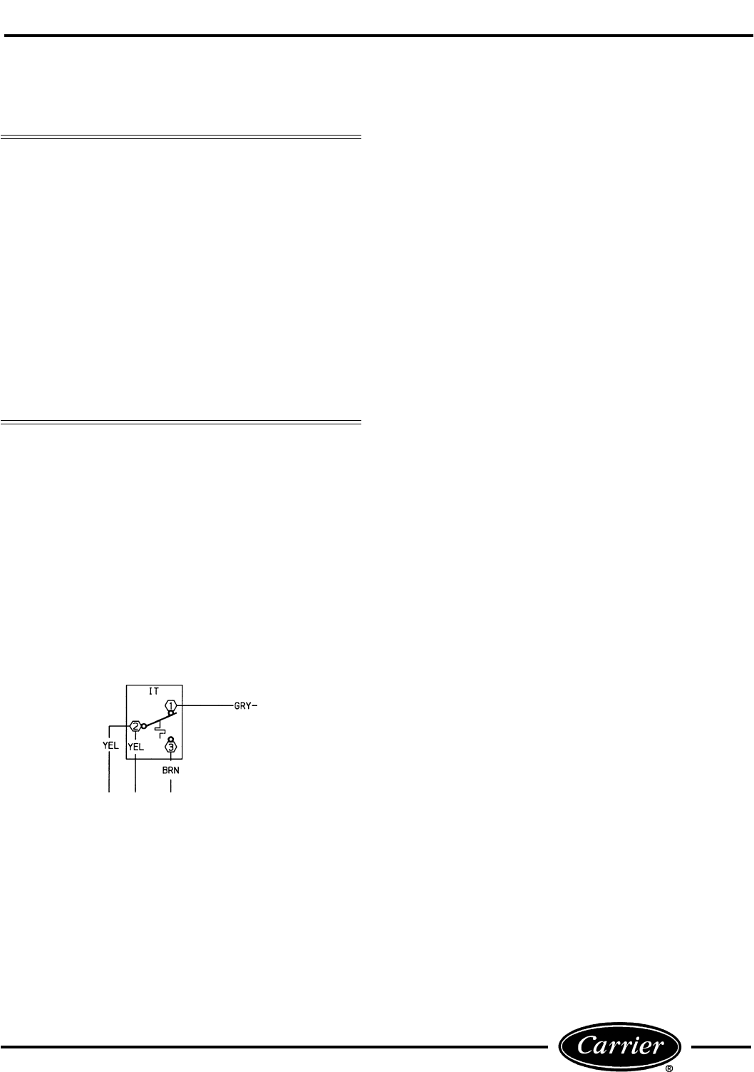
■ INDOOR THERMOSTAT (Heat/Cool and Cool Only
Units) (Figure 48) — The thermostat maintains the
selected temperature by cycling the compressor on and
off during cooling operation and the electric heater
during heating operation. The thermostat DOES
NOT switch from heating to cooling, or cooling
to heating. If the switch is in the CYCLE position,
then the fan will be cycled off when the thermostat
satisfies.
To verify the operation of the thermostat switch, a con-
tinuity test may be performed as follows:
1. Turn off unit power as described in UNIT
DISASSEMBLY section.
2. Remove wire leads from thermostat. Note their
locations to ease re-assembly.
3. Place one of the leads of the continuity tester on
the terminal marked 2, and the other lead on
either the terminal marked 1 or the terminal
marked 3.
4. Adjust the thermostat up or down to verify the
contacts of the switch open and close. When veri-
fying continuity of a closed switch, the ohm read-
ing should be 0 ohms. An open switch will show
OL on the meter.
5. When testing is complete, reconnect the leads.
■ INDOOR THERMOSTAT (Heat Pump Units)
(Figure 49) — The heat pump indoor thermostat uses a
two-stage switch for the heating mode. The first stage
engages the compressor and reversing valve, and the
unit operates in normal heat pump mode. The indoor
thermostat maintains the selected temperature by
cycling the compressor on and off in cooling mode. In
the heating mode, the indoor thermostat will cycle the
compressor or the heater, depending on the difference
between the actual room temperature and the thermo-
stat temperature setting.
When the room temperature is more than 4 F cooler
than the indoor thermostat setting, the second heating
stage of the indoor thermostat engages the electric
heat strip. This design feature allows the user to rap-
idly warm the room with the electric heat strip by
turning the thermostat to its highest setting. When
room temperatures approach the desired temperature,
the user may adjust the thermostat to a personal
comfort setting, which allows for normal heat pump
operation.
NOTE: For outdoor coil temperatures below approxi-
mately 20 F, the outdoor frost thermostat prevents
heat pump mode operation and immediately engages
the electric heat strip upon a call for heating. The elec-
tric heat strip is NEVER energized at the same time
as the compressor.
To verify operation of the heat pump indoor thermo-
stat switch, a continuity test may be performed as
follows:
1. Turn off unit power as described in UNIT
DISASSEMBLY section.
2. Remove wire leads from thermostat. Note their
locations to ease re-assembly.
3. To test stage A, place one lead of the continuity
tester on the terminal marked 2, and the other
lead on either the terminal marked 1 or the termi-
nal marked 3.
4. Adjust the thermostat up or down to verify the
contacts of the switch open and close. When veri-
fying continuity of the closed switch, the reading
on the meter should be 0 ohms. An open switch
will show OL on the meter.
5. To test stage B contacts, place one lead of the con-
tinuity tester on contact 5 and the other lead on
either contact 4 or contact 6.
6. Adjust the thermostat up or down to verify the
contacts of the switch open and close as in Step 4.
7. When testing is complete, reconnect the leads.
Consider the following safety issues:
• Prior to performing any service or maintenance on
electrical equipment you must Disconnect All
Power.
• New and unfamiliar tasks should be performed
under the supervision of an experienced service
technician.
• Personal protective equipment, such as safety
glasses and work gloves, should be worn.
• The floor around the work area should be clean and
free of debris.
• Make sure tools are the correct tools for job, and
that they are working properly and in good
condition.
• The 52C,P unit may weigh up to 150 pounds. Use a
lifting device or ask for assistance if the unit must
be moved.
FIGURE 48 — INDOOR THERMOSTAT (IT)
CONTACTS, ALL 52CE, PE MODELS
LEGEND (Figures 48-50)
COMP — Compressor
HTR — Heater
IT — Indoor Thermostat
OFT — Outdoor Frost Thermostat
OL — Overload
PLS — Primary Limit Switch
SLS — Secondary Limit Switch
52C,P
SERIES
26
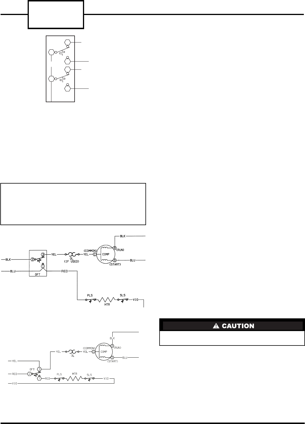
■ OUTDOOR FROST THERMOSTAT (Heat Pump
Units) (Figure 50A and 50B) — The Outdoor Frost
Thermostat (OFT) is a thermostat that uses a single-
pole switch with a manual override selector. The ther-
mostat switches between electric heat and compressor
operation when the temperature of the outdoor coil
falls below 20 F or rises above 35 F. Switching the
override selector to electric heat disables the reverse
cycle operation of the thermostat and is manually
switched to electric heat operation.
To verify the OFT is operational, a continuity test may
be performed as follows:
1. Turn off unit power as described in UNIT
DISASSEMBLY section.
2. Remove the leads from the OFT. Note their loca-
tions to ease re-assembly.
3. Connect the continuity tester to the switch termi-
nals marked 1 and 2.
4. Rotate the override switch to the electric heat set-
ting and verify that there is continuity between
terminals 1 and 2.
5. To check the other contacts, move the lead on ter-
minal 1 to terminal 3. Rotate the override switch
to the heat pump setting. There should now be
continuity between terminals 2 and 3.
6. Once the test is complete, reconnect the leads.
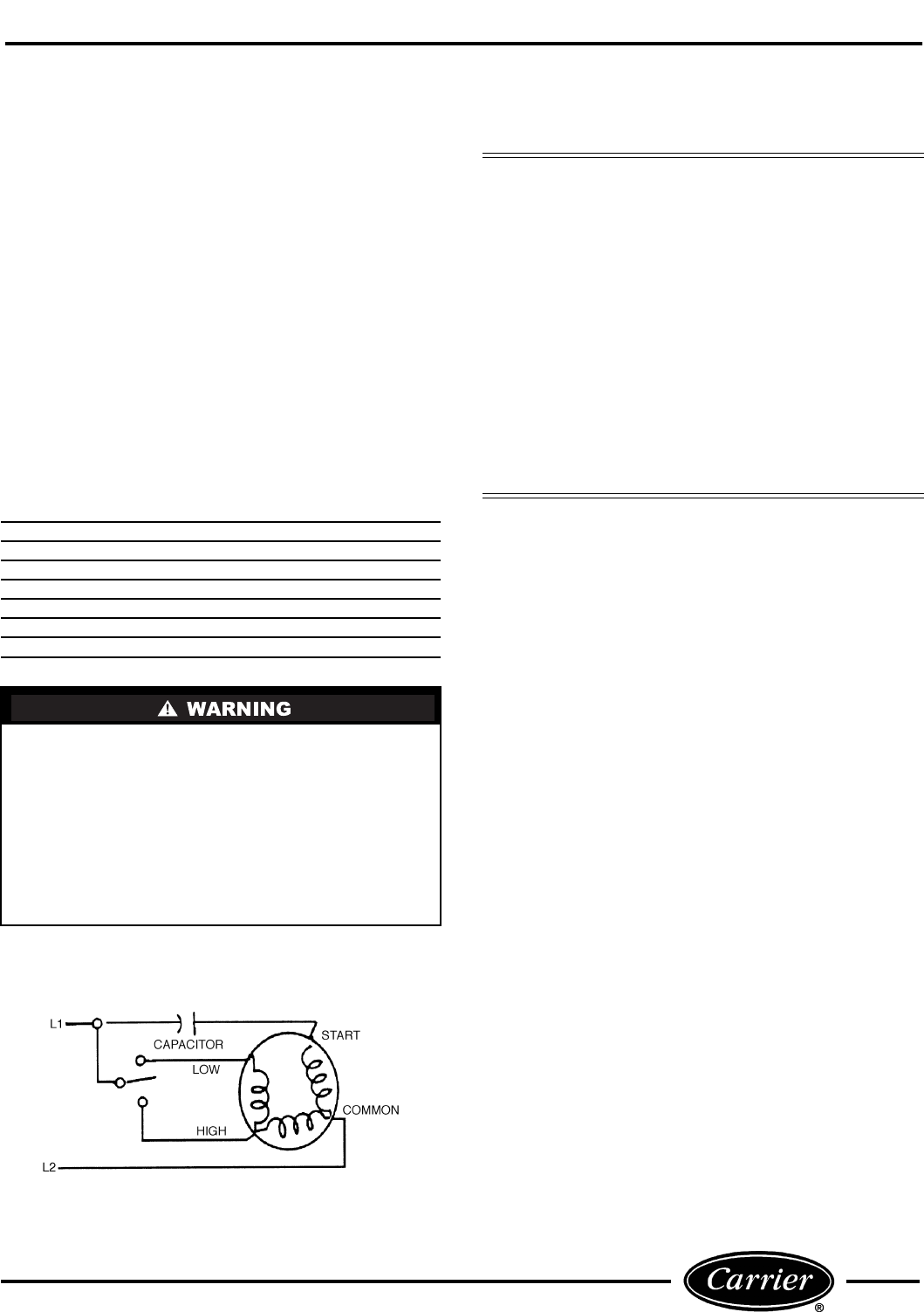
■ CAPACITOR — The 52C,P units use a dual
capacitor. One part of the capacitor is used with the
fan motor. The other part of the capacitor is used by
the compressor.
Run circuits on single-phase compressor motors use
capacitors which dramatically affect the motor opera-
tion. Run capacitors are connected to the motor circuit
at all times.
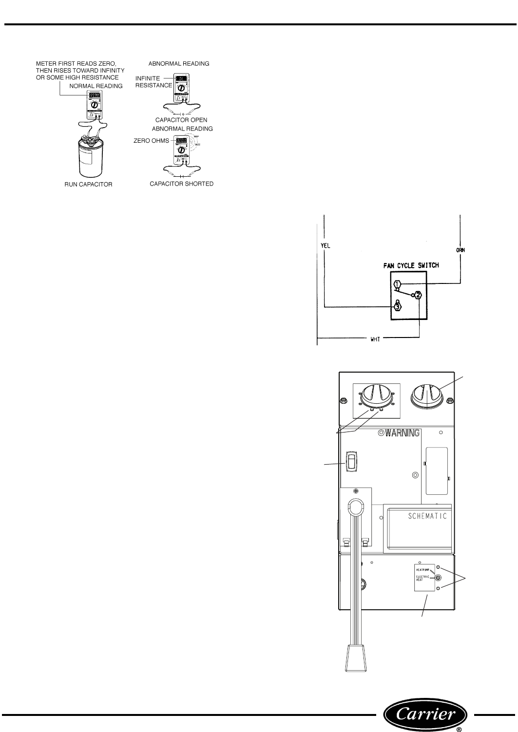
To evaluate the capacitor, perform a visual check first.
A shorted capacitor may give a visual indication of its
failure. For example, the pop-out hole at the top of a
start capacitor may bulge or blow out. A run capacitor
may bulge or leak. In these instances, the capacitor
must be replaced with one recommended by the manu-
facturer. If there are no visual signs of capacitor fail-
ure, testing of the capacitor resistance may be done
with a volt-ohmmeter as detailed below:
1. Turn off unit power as described in UNIT
DISASSEMBLY section but do not unplug the
service cord; it will supply ground connection for
the unit chassis. Check to ensure power is off
and LOCKED OUT.
2. Connect one lead of a 20,000 ohm, 2-watt resistor
to the center group of terminals on the dual capac-
itor. Attach the other lead from the resistor to an
unpainted metal section of the unit chassis. This
allows that section of the dual capacitor to dis-
charge. Repeat this process between the other
group of terminals.
3. Locate and disconnect the wires from the start
and/or run capacitor to isolate them from the
remainder of the circuit. Refer to the unit wiring
diagram if you need assistance locating wires.
4. Perform capacitor test. Set up the volt-ohmmeter
to measure resistance by connecting terminals C
to FAN and C to HERM on the meter. See
Figure 51.
IMPORTANT: Placing the override switch to elec-
tric heat mode operation will disable the compres-
sor for ALL heating or cooling operations (for all
units except RC units). Placing the override switch
to electric heat mode operation on RC units will
only disable the compressor in heating mode.
Capacitors are capable of holding charge similar to a
battery and may cause an electrical shock.
FIGURE 50A — OUTDOOR FROST THERMOSTAT
(OFT) CONTACTS, ALL 52CQ, PQ UNITS WITH
MOUNTED CONTROLS
FIGURE 50B — OUTDOOR FROST THERMOSTAT
(OFT) CONTACTS, ALL 52CQ, PQ UNITS WITH
WALL THERMOSTAT CONTROL
ORN
BLK
BLU
GRY
BRN
IT
2
1
3
4
6
5
FIGURE 49 — INDOOR THERMOSTAT (IT)
CONTACTS, ALL 52CQ, PQ MODELS
27
5. The reading on the meter should first indicate
zero, or a low resistance, then slowly rise toward
infinity or some high value or measurable resis-
tance. This indicates the capacitor is most likely
good. If the reading goes to zero or a low resis-
tance and stays there, the capacitor is likely
shorted and needs replacement. If the reading
immediately indicates infinity, the capacitor is
likely open and must be replaced.
6. Replace the capacitor if failed and rewire accord-
ing to the WIRING SCHEMATICS located in the
control box of the unit.
■ FAN CYCLE SWITCH — The fan cycle switch has
2 operating modes, continuous (CON) and cycle (CYC).
To verify the fan cycle switch is operational, a continu-
ity test may be performed as follows:
1. Turn off unit power as described in UNIT
DISASSEMBLY section.
2. Label and remove the leads connected to fan cycle
switch. See Figure 52.
3. Connect the volt-ohmmeter for 1X ohms and check
for continuity from terminal 2 to 1 then change
the switch position and check for continuity from
terminal 2 to 3.
4. Once test is complete, reconnect the leads.
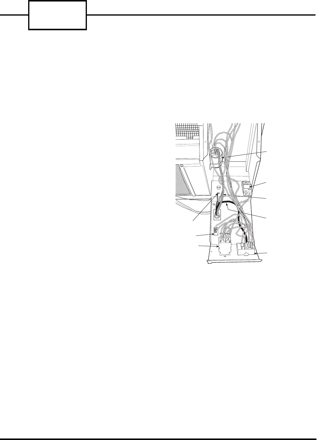
ELECTRICAL COMPONENTS
REMOVAL AND REPLACEMENT
■ INDOOR THERMOSTAT — To remove the indoor
thermostat, perform the following steps:
1. Turn off unit power as described in UNIT
DISASSEMBLY section.
2. Remove front panel.
3. Remove thermostat knob to expose 2 Phillips head
mounting screws.
4. Open the control box as described in the UNIT
DISASSEMBLY section of this manual.
5. Carefully remove the thermostat bulb from the
clip by gently pressing it down and out of the clip.
6. Remove the leads from the indoor thermostat.
Note the wire locations to ease re-assembly.
7. Remove the 2 screws mounting the thermostat to
the control box. Route thermostat bulb and capil-
lary out of control box.
8. Remove thermostat.
9. Reverse Steps 1-8 to reinstall.
■ OUTDOOR FROST THERMOSTAT (Heat Pump
Units) — To remove the outdoor frost thermostat
(OFT), perform the following steps:
1. Turn off unit power as described in UNIT
DISASSEMBLY section.
2. Remove front panel.
3. Remove the 2 screws mounting the thermostat to
the bottom of the control box. See Figure 53.
FIGURE 51 — CAPACITOR TEST
TEMPERATURE
CONTROL
STANDOFF
PINS
FAN CYCLE
SWITCH
OUTDOOR FROST
THERMOSTAT
(HEAT PUMP
UNITS ONLY)
80
85
90 60
65
70
75
CON
CYC
SELECT0R
SWITCH
OFT
MOUNTING
SCREWS
FIGURE 53 — 52C,P OPERATING CONTROLS
FIGURE 52 — FAN CYCLE SWITCH (3 Terminal)
52C,P
SERIES
28
4. Remove the thermostat capillary from the outdoor
coil and clip any wire ties holding the capillary in
place.
5. Disconnect the wires and carefully remove the
thermostat and capillary from the unit, noting
location of wires for easy re-assembly.
6. Reverse Steps 1-5 to reinstall.
■ CAPACITOR — To remove the capacitor, perform
the following steps:
1. Turn off unit power as described in UNIT
DISASSEMBLY section.
2. Open the control box as detailed in the UNIT
DISASSEMBLY section of this manual.
3. Properly discharge the capacitor as described in
the Capacitor section under Component Opera-
tion and Troubleshooting.
4. Remove the leads to the capacitor. Note the wire
locations to ease re-assembly.
5. Remove the screw holding the capacitor.
6. Remove capacitor.
7. Reverse Steps 1-6 to reinstall.
■ FAN CYCLE SWITCH — The fan cycle switch is
located on the front of the control box. To remove the
fan cycle switch, perform the following steps:
1. Turn off unit power as described in UNIT
DISASSEMBLY section.
2. Open the control box as described in UNIT
DISASSEMBLY section of this manual.
3. Remove the 3 wires from the fan cycle switch. See
Figure 54 for location, noting location of wires for
re-assembly.
4. Push the snaps of the switch housing toward the
switch with a pair of pliers or small screwdriver.
Gently push the switch out of the housing.
5. Reverse Steps 1-4 to reinstall.
■ SELECTOR SWITCH — To remove the selector
switch from the unit, perform the following steps:
1. Turn off unit power as described in UNIT
DISASSEMBLY section.
2. Remove selector switch knob. See Figure 53.
3. Open control box as described in the UNIT
DISASSEMBLY section of this manual.
4. Remove all the wires to the selector switch. Label
wires to simplify re-assembly. See Figure 54.
5. Remove the 2 screws mounting the switch and
remove switch.
6. Reverse Steps 1-5 to reinstall.
PLAIN WIRE (L1)
TO ROTARY SWITCH
GROUND SCREW
FAN CYCLE
SWITCH
INDOOR
THERMOSTAT SELECTOR
SWITCH
CAPACITOR
OUTDOOR FROST
THERMOSTAT
RIBBED WIRE (L2)
TO CAPACITOR (C)
POWER CORD
POWER CORD
FIGURE 54 — COMPONENT LOCATIONS
IN OPEN CONTROL BOX
29
FAN MOTOR
The fan motor is a permanent split capacitor (PSC)
type motor. This motor is common in air-conditioning
system applications. A PSC motor does not require the
use of a relay and always has a run capacitor con-
nected between the run and start windings of the
motor. See Figure 55.
The 52C,P series fan motor has a motor shaft extended
through both ends. It powers both the indoor and the
outdoor fans. It has permanently sealed bearings that
require no lubrication. There are many different fan
motor models, but they typically are 2-speed and in
2 voltage categories, 208/230 and 265 volts.
FAN MOTOR TROUBLESHOOTING
Refer to Figure 56 for a basic fan motor troubleshoot-
ing chart.
■ TOOLS NEEDED — The following list includes rec-
ommended tools and devices for working on the fan
motor of 52C,P units.
The Manufacturer reserves the right to discontinue, or
change at any time, specifications or designs without
notice and without incurring obligations.
BASIC FAN MOTOR ELECTRICAL TESTS
There are 2 basic electrical tests for PSC fan motors
that will determine the electrical state of the motor.
The first test requires checking the electrical resis-
tance between the motor windings. The second test
requires checking the electrical resistance between the
motor windings and ground. These tests may be
accomplished by performing the following steps:
1. DISCONNECT ALL POWER TO UNIT.
2. Open the control box as detailed in the UNIT
DISASSEMBLY section.
3. Label and disconnect the fan motor wires from
the selector switch and capacitor as shown in
Figure 54. Two-speed motors have 2 wires on the
capacitor and 2 wires on the push button switch.
4. Measure and record the resistance between the
black wire and each of the other wires. Make sure
the motor is cool before attempting to measure
resistance. The internal thermostat of the motor
may be electrically open and will not close until
the motor cools. See Figure 57 for typical motor
winding resistance measurements. The resistance
values in the table are approximate. Values that
are within 10% of those listed are acceptable. If
the motor in your model is not listed, find a motor
of similar horsepower and voltage on the chart
and compare it to the resistance measurements of
your motor.
5. Measure the resistance of each of the motor wires
to the motor casing. The resistance should be infi-
nite. Make sure the motor is cool before attempt-
ing to measure resistance. The internal
thermostat of the motor may be electrically open
and will not close until the motor cools. A motor
that has measurable resistance to ground is
shorted to ground and must be replaced.
Gloves
Safety Glasses
Regular and Phillips Head Screw Drivers
Small Adjustable Wrench
Channel Lock Pliers
Volt-ohmmeter
5/16-in. Nut Driver
Before cleaning, servicing, performing maintenance
or removing the chassis from the wall sleeve, discon-
nect all power to the unit to avoid the possibility of
electrical shock and personal injury. Only trained
and qualified service personnel should perform
installation and service procedures on these units.
Untrained personnel may perform basic mainte-
nance tasks such as cleaning and replacing filters.
Refer to UNIT DISASSEMBLY section of this man-
ual for proper procedures to disconnect power to
52C,P units.
Consider the following safety issues:
• Prior to performing any service or maintenance on
electrical equipment you must Disconnect All
Power.
• New and unfamiliar tasks should be performed
under the supervision of an experienced service
technician.
• Personal protective equipment, such as safety
glasses and work gloves, should be worn.
• The floor around the work area should be clean and
free of debris.
• Make sure tools are the correct tools for the job,
and that they are working properly and in good
condition.
• The 52C,P unit may weigh up to 150 pounds. Use a
lifting device or ask for assistance if the unit must
be moved.
FIGURE 55 — TWO-SPEED, PERMANENT
SPLIT CAPACITOR MOTOR (PSC)
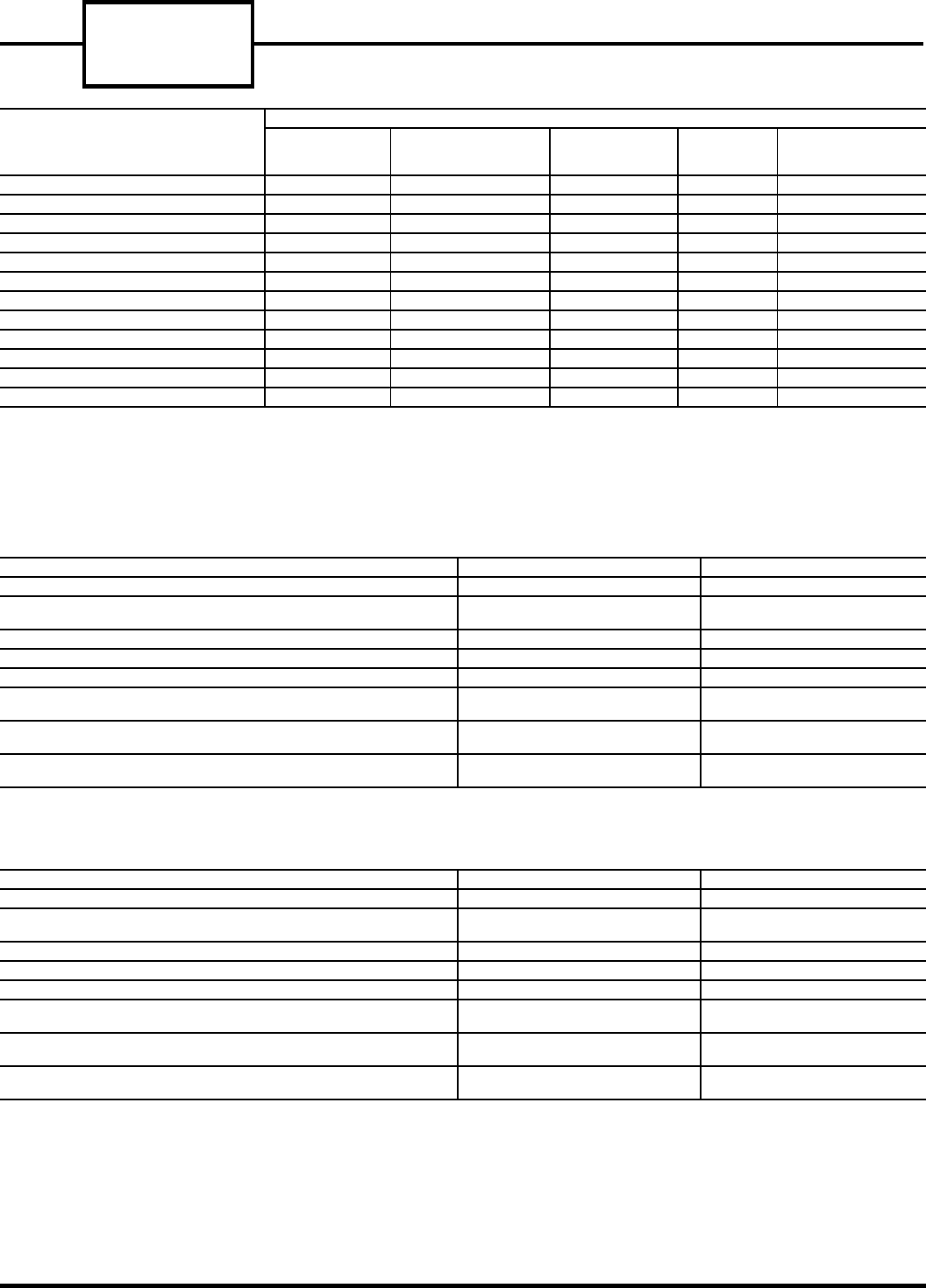
52C,P
SERIES
30
FIGURE 56 — FAN MOTOR TROUBLESHOOTING CHART
TYPICAL 208/230 VOLT MOTORS
NOTE: Resistance values are approximate.
TYPICAL 265 VOLT MOTORS
NOTE: Resistance values are approximate.
FIGURE 57 — TYPICAL 52C,P FAN MOTORS
POSSIBLE CAUSE
SYMPTOM
Motor Hums
But Does
Not Start
Makes No Noise
and Does Not
Start
Starts But
Stops After
Short Time
Starts
But Runs
Slow
Runs On
One Speed,
Not On Others
DEFECTIVE BEARING XXX
CAPACITOR DEFECTIVE XX
SWITCH DEFECTIVE XX
LOW LINE VOLTAGE XXX
SHORTED MOTOR WINDING XX X
NO POWER TO UNIT X
INTERNAL THERMOSTAT OPEN X
MISWIRED XXX X
FAN STUCK X
BROKEN MOTOR WIRE XXX X
MOTOR WINDING GROUNDED XX
OPEN MOTOR WINDING XXX X
UNIT 52C,P (BTUH) 7,000/9,000 12,000/15,000
CARRIER MOTOR PART NUMBER HC37GE237 HC37GE238
MANUFACTURER’S
PART NUMBER 5KCP29ECA299A 5KCP29ECA301
MOTOR VOLTAGE 208/230 208/230
MOTOR HORSEPOWER .075 .125
MOTOR SPEEDS 22
RESISTANCE (OHMS)
BLACK TO WHITE WIRE 101.4 90
RESISTANCE (OHMS)
BLACK TO BROWN WIRE 45.8 71
RESISTANCE (OHMS)
BLACK TO RED WIRE 38.8 32.9
UNIT 52C,P (BTUH) 7,000/9,000 12,000/15,000
CARRIER MOTOR PART NUMBER HC29GE236 HC33GE239
MANUFACTURER’S
PART NUMBER 5KCP29FCA315 5KCP29FCA316
MOTOR VOLTAGE 265 265
MOTOR HORSEPOWER .075 .125
MOTOR SPEEDS 22
RESISTANCE (OHMS)
BLACK TO WHITE WIRE 144.0 83.7
RESISTANCE (OHMS)
BLACK TO BROWN WIRE 29.3 39.1
RESISTANCE (OHMS)
BLACK TO RED WIRE 82.1 45.2
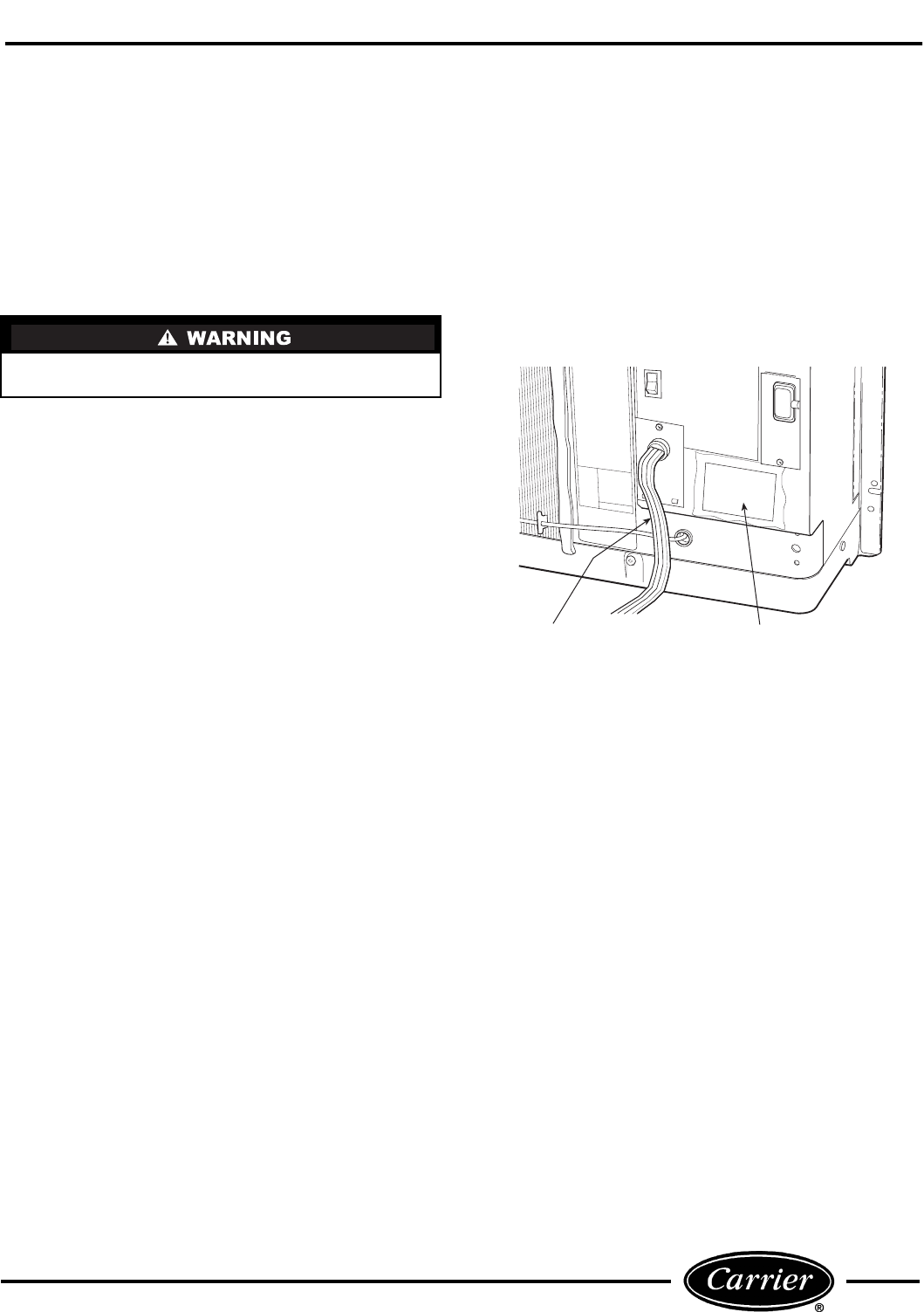
31
FAN MOTOR REPLACEMENT
1. DISCONNECT ALL POWER TO UNIT.
2. Remove the unit from the sleeve as detailed in the
UNIT DISASSEMBLY section and place the unit
on a large flat surface.
3. Remove the discharge deck and grille as detailed
in Remove the Discharge Deck Assembly section.
4. Remove heater plate assembly as detailed in
Accessing the Heater Assembly section. The
blower wheel should now be accessible.
5. Using adjustable pliers, carefully remove the
5/32-in. Allen clip that secures the blower wheel to
the fan shaft. Remove the blower wheel.
6. Open the Control box as described in the UNIT
DISASSEMBLY section, Open the Control
Box. Disconnect the fan motor wires from the
rotary switch and capacitor. All units are
equipped with two-speed motors, which have
2 wires on the capacitor and 2 wires on the rotary
switch. Refer to the unit wiring schematic which
is attached to the front panel of the control box.
See Figure 58.
7. Carefully pull fan motor leads through the parti-
tion hole, located in the back of the control box.
8. Remove the top gussets, as detailed in Remove the
Gussets section.
9. Remove the top half of the condenser orifice as
detailed in Detach the Condenser Orifice From the
Condenser Coil section.
10. Using a Phillips head screwdriver, remove the fan
motor shield. The fan motor mounting screws
should now be accessible. Remove the 3 mounting
screws that secure the fan motor to the motor
mount and remove the fan motor from the unit.
11. Using needle nose pliers, remove condenser fan
hub clamp. Slide condenser fan off fan motor
shaft.
12. Re-install the new fan motor by reversing Steps 1
through 11.
Safety glasses should be worn to protect eyes in the
event the spring clip breaks free from pliers.
WIRING
SCHEMATIC
POWER
CORD
FIGURE 58 — LOCATION OF WIRING SCHEMATIC
ON FRONT PANEL OF CONTROL BOX
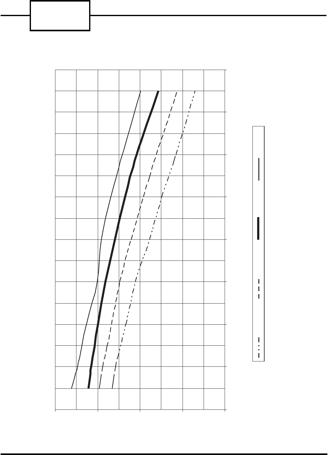
52C,P
SERIES
32
14
16
18
20
22
50 60 70 80 90 100 110 120 130
Outdoor Air Temperature (F) (40% RH)
70 F Indoor 75 F Indoor 80 F Indoor 85 F Indoor
Indoor Coil Delta Temperature (F)
FIELD TEMPERATURE CHARTS
Refer to Figures 59-67 for field temperature data.
FIGURE 59 — 52C AND 52P 7000 BTU UNIT FIELD TEMPERATURE CHART — HIGH COOL — 50% RH
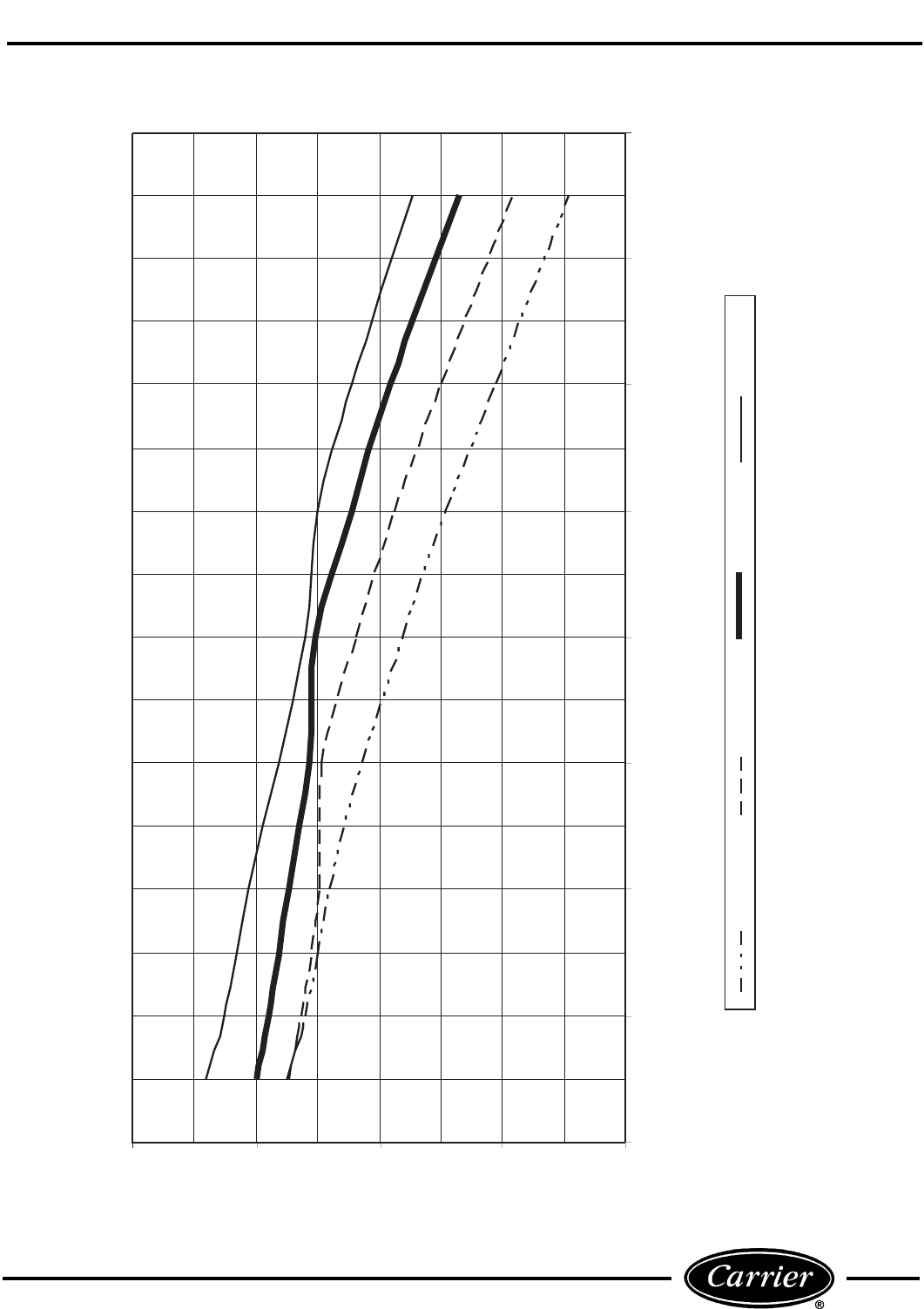
33
16
18
20
22
24
50 60 70 80 90 100 110 120 130
Outdoor Air Temperature (F) (40% RH)
70 F Indoor 75 F Indoor 80 F Indoor 85 F Indoor
Indoor Coil Delta Temperature (F)
FIGURE 60 — 52C AND 52P 9000 BTU UNIT FIELD TEMPERATURE CHART — HIGH COOL — 50% RH
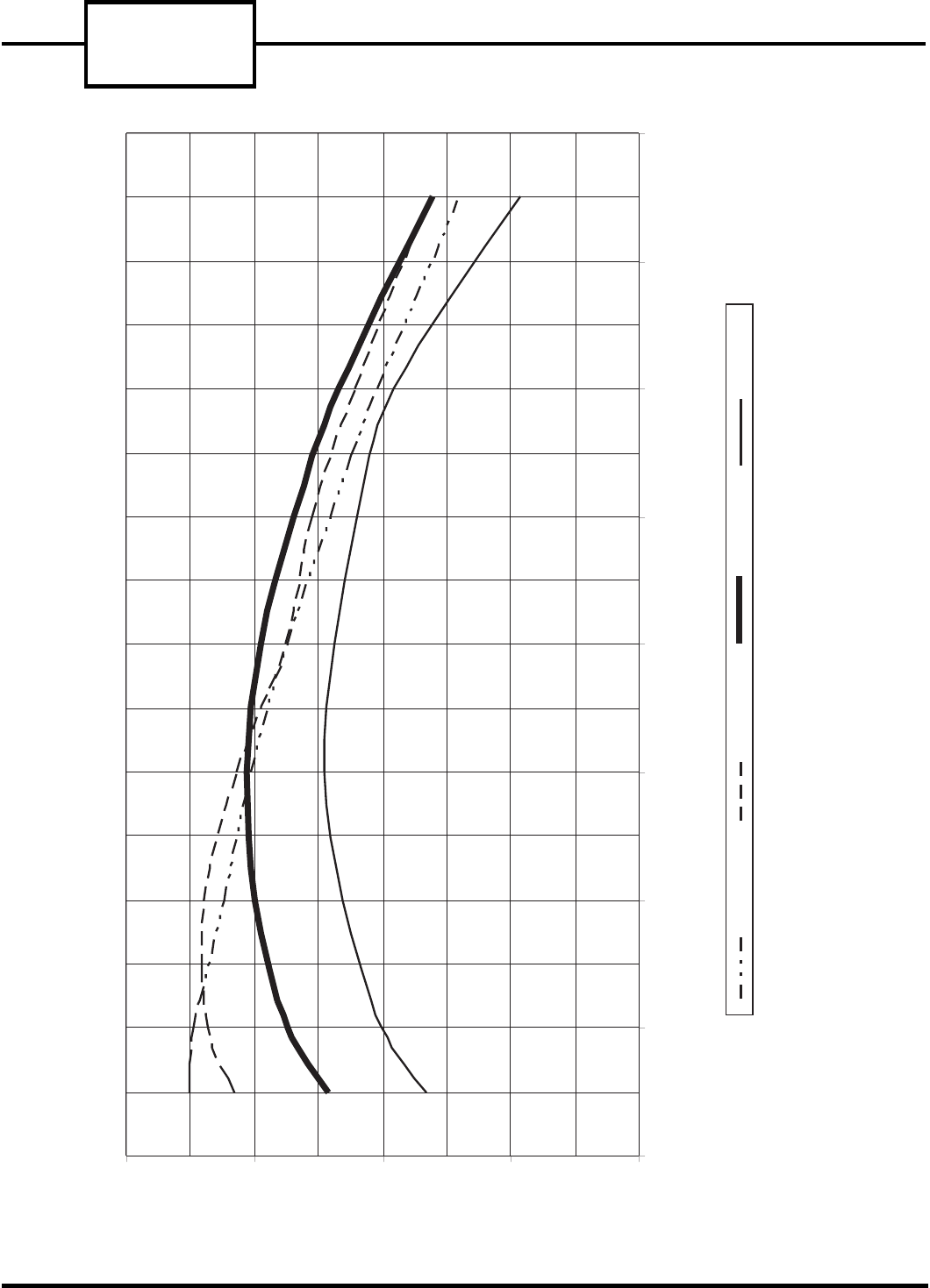
52C,P
SERIES
34
18
20
22
24
26
50 60 70 80 90 100 110 120 130
Outdoor Air Temperature (F) (40% RH)
70 F Indoor 75 F Indoor 80 F Indoor 85 F Indoor
Indoor Coil Delta Temperature (F)
FIGURE 61 — 52P 12,000 BTU UNIT FIELD TEMPERATURE CHART — HIGH COOL — 50% RH
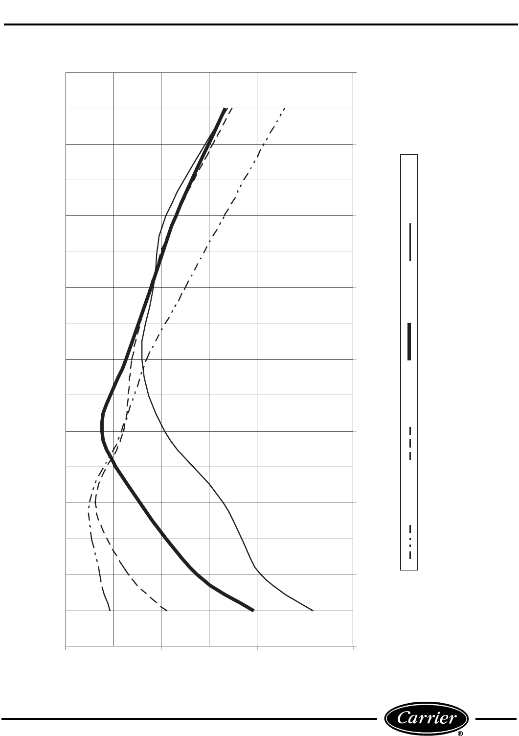
35
20
22
24
26
50 60 70 80 90 100 110 120 130
Outdoor Air Temperature (F) (40% RH)
70 F Indoor 75 F Indoor 80 F Indoor 85 F Indoor
Indoor Coil Delta Temperature (F)
FIGURE 62 — 52CQ 12,000 BTU HEAT PUMP UNIT FIELD TEMPERATURE CHART — HIGH COOL — 50% RH
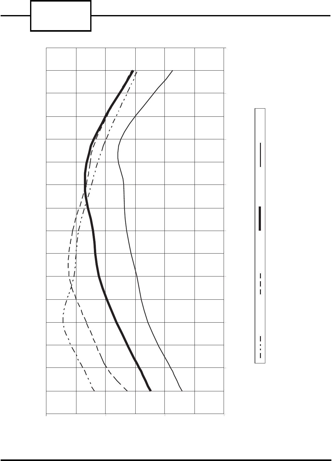
52C,P
SERIES
36
18
20
22
24
50 60 70 80 90 100 110 120 130
Outdoor Air Temperature (F) (40% RH)
70 F Indoor 75 F Indoor 80 F Indoor 85 F Indoor
Indoor Coil Delta Temperature (F)
FIGURE 63 — 52CE 12,000 BTU HEAT/COOL UNIT FIELD TEMPERATURE CHART — HIGH COOL — 50% RH
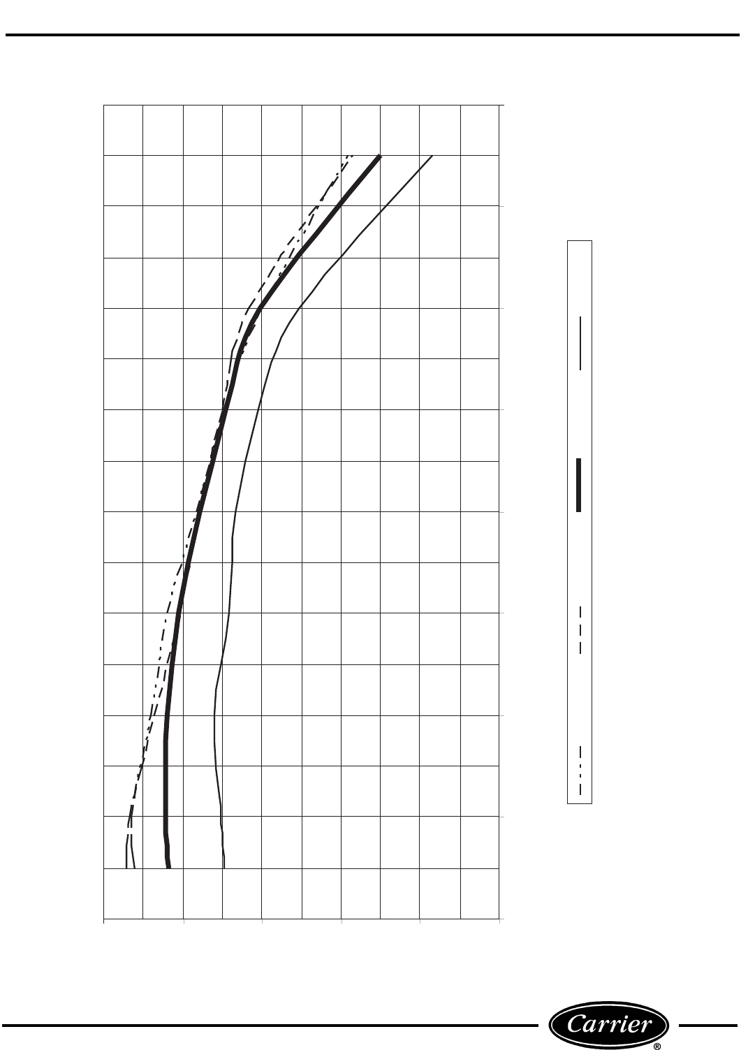
37
18
20
22
24
26
28
50 60 70 80 90 100 110 120 130
Outdoor Air Temperature (F) (40% RH)
70 F Indoor 75 F Indoor 80 F Indoor 85 F Indoor
Indoor Coil Delta Temperature (F)
FIGURE 64 — 52C AND 52P 15,000 BTU UNIT FIELD TEMPERATURE CHART — HIGH COOL — 50% RH
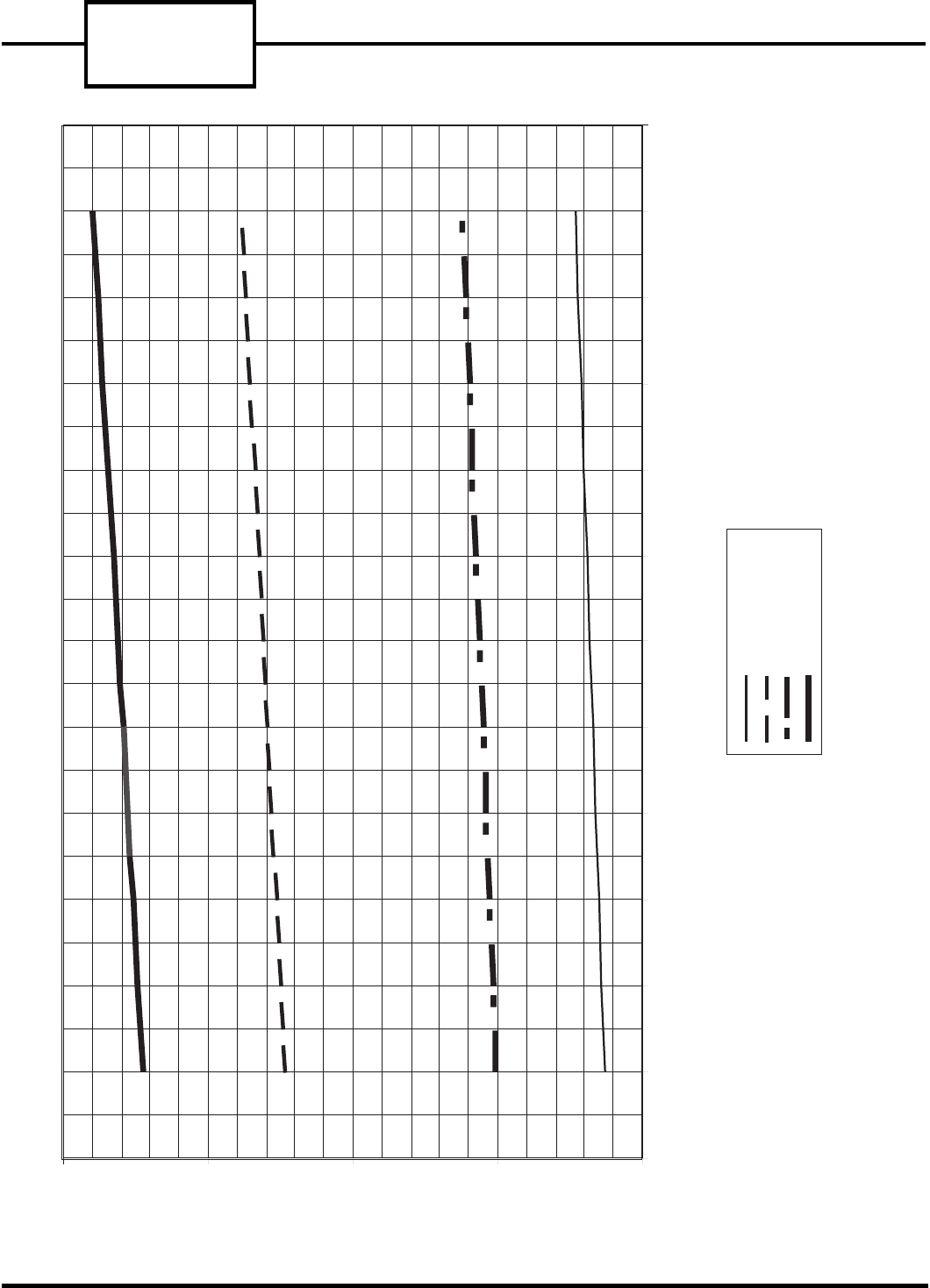
52C,P
SERIES
38
20
25
30
35
40
50 52 54 56 58 60 62 64 66 68 70 72 74
Indoor Entering Air Temperature (F)
Indoor Air Temperature Rise (F)
208 V, 2.3 kW
208 V, 3.4 kW
230/265 V, 2.3 kW
230/265 V, 3.4 kW
FIGURE 65 — 52C AND 52P 7000/9000 BTU UNIT FIELD TEMPERATURE CHART FOR ELECTRIC HEAT — HIGH HEAT
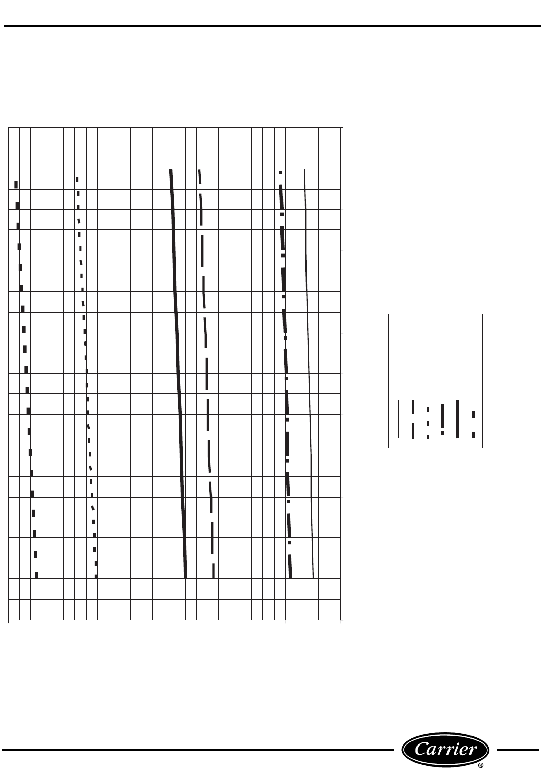
39
15
20
25
30
35
40
45
50 52 54 56 58 60 62 64 66 68 70 72 74
Indoor Entering Air Temperature (F)
208 V, 2.3 kW
208 V, 3.4 kW
208 V, 5.0 kW
230/265 V, 2.3 kW
230/265 V, 3.4 kW
230/265 V, 5.0 kW
Indoor Air Temperature Rise (F)
FIGURE 66 — 52C AND 52P 12,000/15,000 BTU UNIT FIELD TEMPERATURE CHART FOR ELECTRIC HEAT — HIGH HEAT
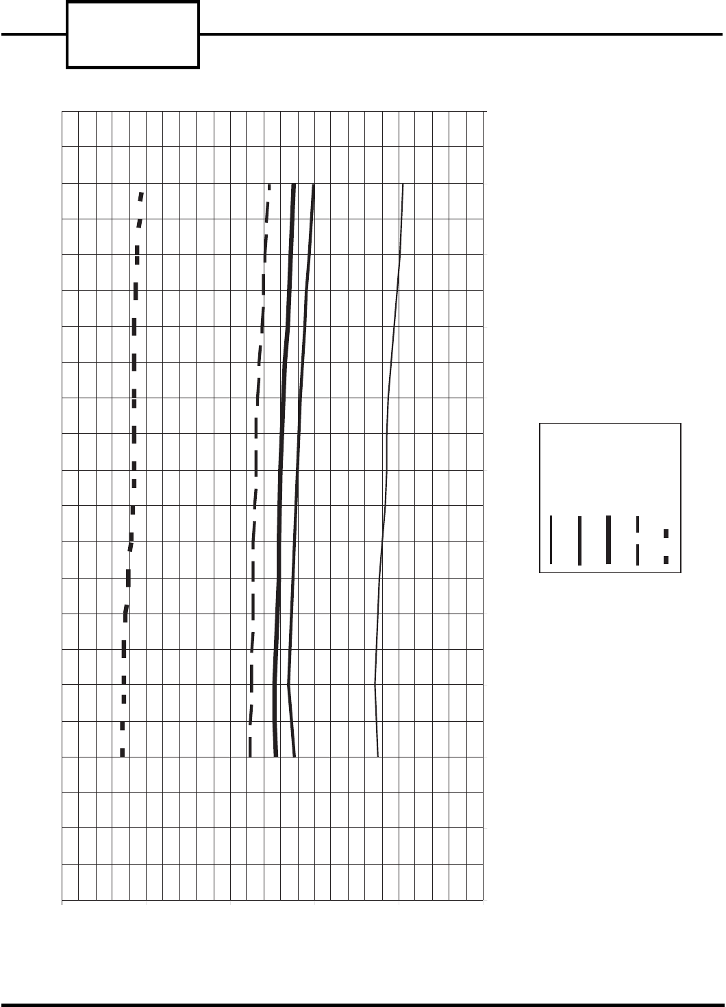
52C,P
SERIES
40
15
20
25
30
35
40
50 52 54 56 58 60 62 64 66 68 70 72
Indoor Entering Air Temperature (F)
7,000 Btu
9,000 Btu
52P-12,000 Btu
52C-12,000 Btu
15,000 Btu
Indoor Air Temperature Rise (F)
FIGURE 67 — 52C AND 52P 7,000-15,000 BTU UNIT FIELD TEMPERATURE CHART FOR REVERSE CYCLE HEAT — HIGH HEAT
47 F (DRYBULB)/43 F (WET BULB) OUTDOOR AIR
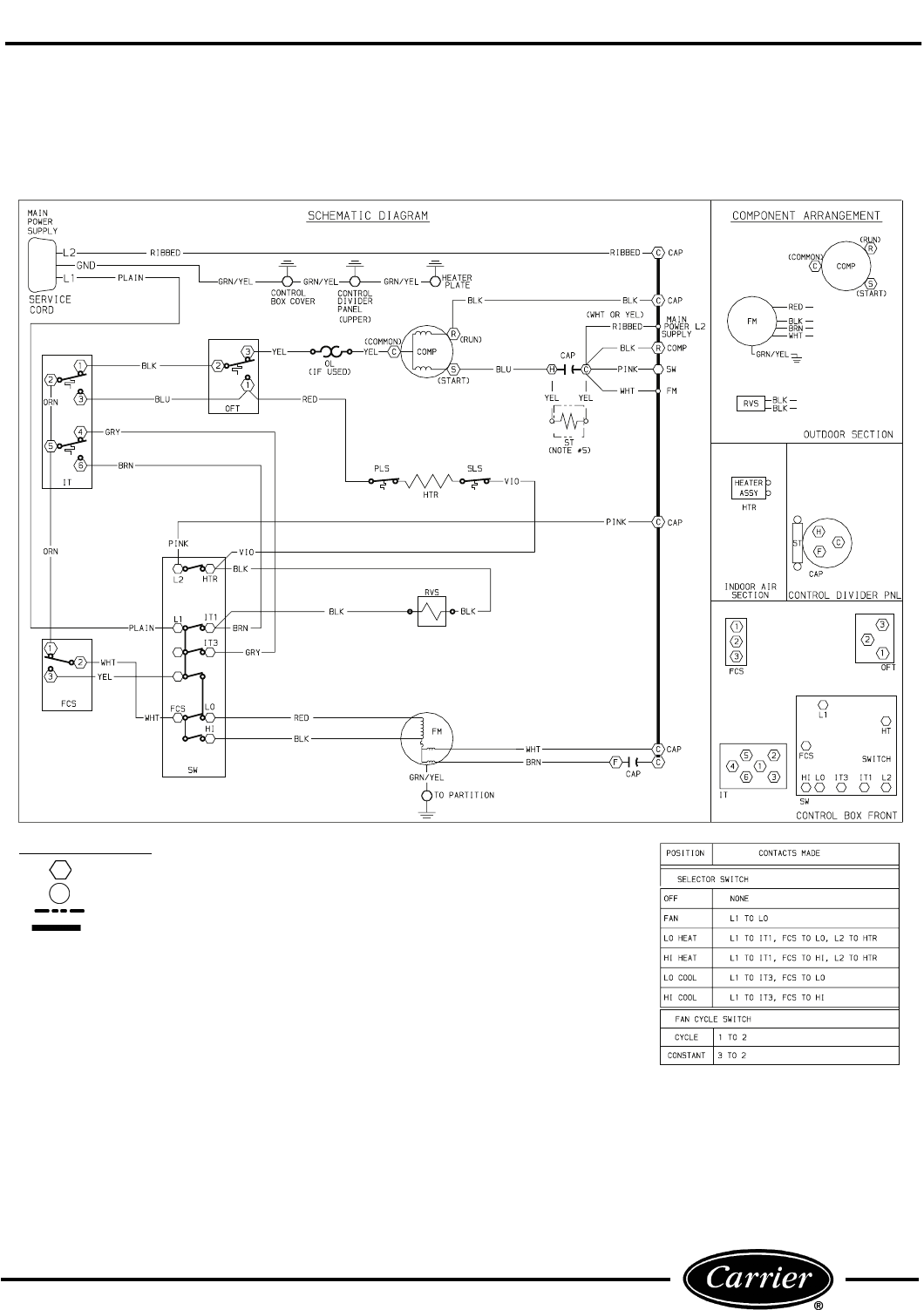
41
WIRING DIAGRAMS
Refer to Figures 68-72 for Typical Wiring Schematics.
NOTE: Figures 68-72 should not be substituted for the schematic located on control box.
FIGURE 68 — 52CQ & 52PQ — TYPICAL WIRING SCHEMATIC FOR
STANDARD HEAT PUMP UNITS
COMPONENT LEGEND
Component Connection (Marked)
Component Connection (Unmarked)
Accessory or Optional Wiring
To Indicate Common Potential Only
Not To Represent Wire
CAP —Capacitor
COMP —Compressor
FM —Fan Motor
FCS —Fan Cycle Switch
HTR —Heater
IT —Indoor Thermostat
NEC —National Electrical Code
OFT —Outdoor Frost Thermostat
OL —Overload
PLS —Primary Limit Switch
RVS —Reversing Valve Solenoid
SLS —Secondary Limit Switch
ST —Start Thermistor
SW —Switch
NOTES:
1. Recommended for use on grounded power sup-
ply only.
2. Compressor and fan motor thermally protected.
3. Use copper conductors only.
4. All wiring must conform with NEC and local
codes.
5. Dashed lines indicate components when used.
6. OFT determines whether to bring on compres-
sor heat or electric heat.
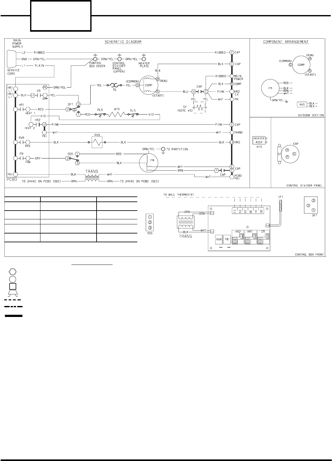
52C,P
SERIES
42
TYPICAL THERMOSTAT INTERFACE
1. If ‘W’ is ON, then ‘FR’ is forced ON (regardless of ‘G’) & ‘CR’ is forced OFF.
2. If ‘Y’ is ON, then ‘FR’ is forced ON (regardless of ‘G’).
3. If IFT (indoor coil) is < 35° F, then ‘CR’ is forced OFF until IFT is > 39° F.
T’STAT OUTPUT: RC CONTROLER OUTPUT: UNIT OPERATION:
‘G’ — 24 VAC
‘G’ — 0 VAC
‘FR’ — LINE VAC
‘FR’ — 0 VAC FA N
‘Y’ — 24 VAC
‘O’ — 0 VAC
‘HR1 & HR2’ — LINE VAC
‘RVR’ — LINE VAC HEATING
‘W’ — 24 VAC ‘HR1 & HR2’ — LINE VAC HEATING
‘Y’ — 24 VAC
‘O’ — 24 VAC
‘CR’ — LINE VAC
‘RVR’ — 0 VAC COOLING
‘R’ — 24 VAC
‘C’ — COMMON
‘R’ — 24 VAC OUTPUT
‘C’ — COMMON
POWER TO WALL
THERMOSTAT
NOTES:
1. Recommended for use on grounded power supply only.
2. Compressor and fan motor thermally protected.
3. Use copper conductors only.
4. All wiring must conform with NEC and local codes.
5. Dashed lines indicate components when used.
6. Field control wire suitable for NEC class 2 control circuit, at
24 volts.
7. OFT determines whether to bring on compressor heat or
electric heat.
FIGURE 69 — 52CQ AND 52 PQ — TYPICAL WIRING SCHEMATIC FOR
WALL THERMOSTAT HEAT PUMP UNITS
Component Connection (Marked)
Component Connection (Unmarked)
Terminal Board Connection
Field Splice
Field Control Wiring
Accessory or Optional Wiring
To Indicate Common Potential Only
Not To Represent Wire
CAP —Capacitor
COMP —Compressor
FM —Fan Motor
COMPONENT LEGEND
HTR —Heater
IFT —Indoor Frost Thermostat
NEC —National Electrical Code
OFT —Outdoor Frost Thermostat
OL —Overload
PCBD —Printed Circuit Board
HR1 —Heater Relay
HR2 —Heater Relay
CR —Compressor Relay
FR —Fan Relay
RVR —Reversing Valve Relay
PLS —Primary Limit Switch
RVS —Reversing Valve Solenoid
SLS —Secondary Limit Switch
SSS —Speed Selector Switch
ST —Start Thermistor
TRANS —Transformer
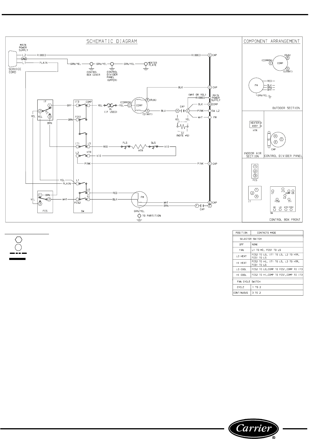
43
FIGURE 70 — 52CE AND 52PE — TYPICAL WIRING SCHEMATIC FOR
STANDARD HEAT/COOL UNITS
COMPONENT LEGEND
Component Connection (Marked)
Component Connection (Unmarked)
Accessory or Optional Wiring
To Indicate Common Potential Only
Not To Represent Wire
CAP —Capacitor
COMP —Compressor
FM —Fan Motor
FCS —Fan Cycle Switch
HTR —Heater
IT —Indoor Thermostat
NEC —National Electrical Code
OL —Overload
PLS —Primary Limit Switch
SLS —Secondary Limit Switch
ST —Start Thermistor
SW —Switch
NOTES:
1. Recommended for use on grounded power sup-
ply only.
2. Compressor and fan motor thermally protected.
3. Use copper conductors only.
4. All wiring must conform with NEC and local
codes.
5. Dashed lines indicate components when used.
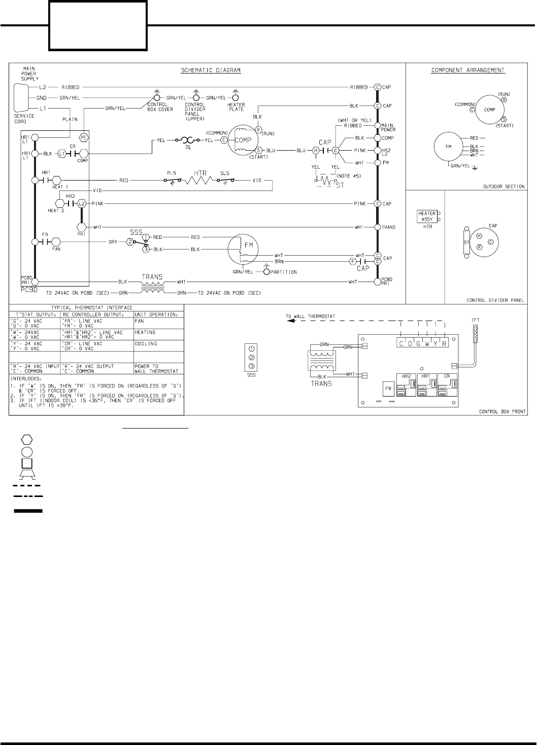
52C,P
SERIES
44
FIGURE 71 — 52CE AND 52PE — TYPICAL WIRING SCHEMATIC FOR
WALL THERMOSTAT CONTROL HEAT/COOL UNITS
NOTES:
1. Recommended for use on grounded power supply only.
2. Compressor and fan motor thermally protected.
3. Use copper conductors only.
4. All wiring must conform with NEC and local codes.
5. Dashed lines indicate components when used.
6. Field control wire suitable for NEC class 2 control circuit, at
24 volts.
Component Connection (Marked)
Component Connection (Unmarked)
Terminal Board Connection
Field Splice
Field Control Wiring
Accessory or Optional Wiring
To Indicate Common Potential Only
Not To Represent Wire
CAP —Capacitor
COMP —Compressor
FM —Fan Motor
HTR —Heater
IFT —Indoor Frost Thermostat
NEC —National Electrical Code
OL —Overload
PCBD —Printed Circuit Board
HR1 —Heater Relay
HR2 —Heater Relay
CR —Compressor Relay
FR —Fan Relay
PLS —Primary Limit Switch
SLS —Secondary Limit Switch
SSS —Speed Selector Switch
ST —Start Thermistor
TRANS —Transformer
COMPONENT LEGEND
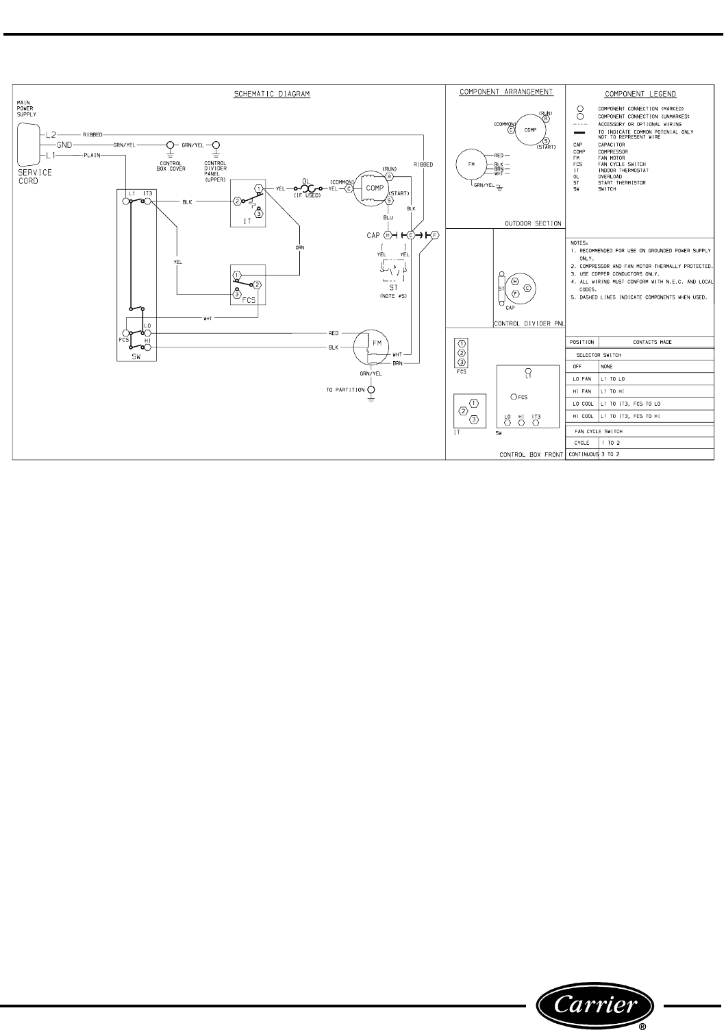
45
FIGURE 72 — 52PC — TYPICAL WIRING SCHEMATIC FOR
STANDARD COOLING ONLY UNITS
52C,P
SERIES
46
MOST FREQUENT PTAC SERVICE QUESTIONS
1. Can remote wall thermostats be used on
standard (AA) models? No, only for use on remote control (RC,RP) models. How-
ever, accessory RC-Retrofit Kit can be ordered to convert
standard units to RC units.
2. Which remote thermostats are acceptable
for use on 52C,P products? HH01AD045 — Manual changeover thermostat
TSTATCCBPC01-B (Heat/Cool) — Non-Programmable
thermostat
TSTATCCBPH01-B (Heat Pump) — Non-Programmable
thermostat
TSTATCCPAC01-B (Heat/Cool) — Digital Programmable
thermostat
TSTATCCPHP01-B (Heat Pump) — Digital Programmable
thermostat
3. How many 52C,P series units can be
controlled by one remote thermostat? Maximum of 4.
4. What is the vent capacity of the
52C,P products? 50 cfm (standalone). Capacity can be increased with the
use of an external exhaust fan.
5. How do the 52C,P series models handle
condensate removal? By using a 2-stage condensate removal system. First
stage uses a slinger ring to pick up condensate and move
it to the outdoor coil to be evaporated. In second stage, a
vortex pump will suck condensate water into the con-
denser airstream where it will be blown onto the outdoor
coil for evaporation.
6. At what temperature will the outdoor
(defrost) thermostat switch the unit (heat
pumps only) into defrost (emergency heat)
mode?
When the outdoor coil temperature falls below 20 F
(outdoor ambient temperature of approximately 35 F)
and will stay in a passive defrost until outdoor coil is
greater than 35 F.
7. Can the PTAC unit be configured to allow
continuous fan operation? Yes. A switch located on the front of the control
box is used to toggle between continuous or cycle
fan mode.
8. Can the discharge air grille be changed to
alter the direction of the airflow? Yes. Remove the 2 screws and flip the grille over
180 degrees.
9. What does the outdoor thermostat
switch do? The selector screw, located on the front of the control
box, prevents the compressor from energizing in
heating mode during subfreezing conditions to ensure
adequate heating capacity. For units with unit-mounted
controls, the switch must be returned to the ‘‘heat pump’’
position for compressor operation during cooling modes.
47
ACCESSORIES
*Extended metal wall sleeve also available in 26 in. and 28 in. depth.
†Custom colors are also available.
ACCESSORY FORM NUMBER PART NUMBER DESCRIPTION
Wall Sleeves 52S-48SI WALL-SLEEVE-1PK Non-Insulated Plastic Wall Sleeve, 1 per pack
WALL-SLEEVE-9PK Non-Insulated Plastic Wall Sleeve, 9 per pack
SLEEVE-INSUL-1PK Insulated Plastic Wall Sleeve, 1 per pack
52S-50SI SLEEVE-STEEL-1PK Insulated Metal Wall Sleeve, 1 per pack
52S-49SI* SLEEVE-EXT24-1PK Extended Metal Wall Sleeve for Deep Wall Applications (24 in. deep), 1 per pack
52C,P-20SI FR-SLEEVE-EXT Friedrich wall sleeve extension to retrofit Carrier PTAC unit into Friedrich 111/2
″ deep (T Series) wall
sleeve. 1 per pack
Exterior Grilles†52S-59SI GRILLE-ALU-STAMP Stamped Aluminum Exterior Grille, Clear Finish
52S-65SI GRILLE-PLA-BROWN Plastic Architectural Rear Grille, Brown
GRILLE-PLA-BEIGE Plastic Architectural Rear Grille, Beige
52S-60SI GRILLE-ALU-CLEAR Aluminum Architectural Exterior Grille, Clear Finish
GRILLE-ALU-WHITE Aluminum Architectural Exterior Grille, White
GRILLE-ALU-BRONZ Aluminum Architectural Exterior Grille, Light Bronze
GRILLE-ALU-MBRNZ Aluminum Architectural Exterior Grille, Medium Bronze
GRILLE-ALU-BROWN Aluminum Architectural Exterior Grille, Brown (Dark Bronze)
GRILLE-ALU-BEIGE Aluminum Architectural Exterior Grille, Beige
GRILLE-ALU-ALPIN Aluminum Architectural Exterior Grille, Alpine (matches Carrier Wall Sleeve)
GRILLE-ALU-PEACH Aluminum Architectural Exterior Grille, Peach
GRILLE-ALU-MELON Aluminum Architectural Exterior Grille, Melon
GRILLE-ALU-LGREY Aluminum Architectural Exterior Grille, Light Grey
GRILLE-ALU-SGREY Aluminum Architectural Exterior Grille, Slate Gray
GRILLE-ALU-RDBRK Aluminum Architectural Exterior Grille, Red Brick
GRILLE-ALU-BLUE Aluminum Architectural Exterior Grille, Blue
GRILLE-ALU-GREEN Aluminum Architectural Exterior Grille, Green
Subbase 52C,P-1SI SUBBASE-NON-ELEC Non-electrical Subbase
52C,P-2SI SUBBASE-230V-15A Electrical subbase with factory-installed 208/230 V, 15 amp receptacle
SUBBASE-230V-20A Electrical subbase with factory-installed 208/230 V, 20 amp receptacle
SUBBASE-230V-30A Electrical subbase with factory-installed 208/230 V, 30 amp receptacle
SUBBASE-265V-15A Electrical subbase with factory-installed 265 V, 15 amp receptacle
SUBBASE-265V-20A Electrical subbase with factory-installed 265 V, 20 amp receptacle
SUBBASE-265V-30A Electrical subbase with factory-installed 265 V, 30 amp receptacle
52C,P-3SI SUBBASE-HARDWIRE Electrical subbase with factory-installed hardwire kit (230/208 V and 265 V)
Subbase
Field-Installed
Kits
52C,P-4SI SUBBASE-SWITCH Field-Installable Switch kit for an electrical subbase
52C,P-5SI SUBBASE-FUSE-15A Field-Installed Fuse Kit (15 amp) for electrical subbase
SUBBASE-FUSE-20A Field-Installed Fuse Kit (20 amp) for electrical subbase
SUBBASE-FUSE-30A Field-Installed Fuse Kit (30 amp) for electrical subbase
Electrical
Connections
52C,P-11SI HARDWIRE-KIT-1PK Permanent power connection to the unit (includes 36″ of flexible conduit and unit-mounted
connector, 230/208 V and 265 V) 1 per pack
52C,P-19SI CONDUIT-INTF-4PK Interface kit for field-supplied conduit to provide permanent power connection (230/208 V and 265 V)
to the unit. Kit includes Molex connector for easy connect/disconnect. 4 per pack
Condensate
Drain Kit
52S-53SI DRAIN-KIT-4PK Attaches to wall sleeve for controlled internal or external disposal of condensate 4 per pack
Wall
Thermostats
N/A HH01AD045 Electro-mechanical Wall Thermostat (Heat/Cool and Heat Pump)
TSTATCCBPC01-B Value Series Electronic Thermostat w/Digital display (Heat/Cool Models)
TSTATCCBPH01-B Value Series Electronic Thermostat w/Digital display (Heat Pump Models)
TSTATCCPAC01-B 7-Day Programmable Electronic Thermostat (Heat/Cool Models)
TSTATCCPHP01-B 7-Day Programmable Electronic Thermostat (Heat Pump Models)
Wall Thermostat
Interface
Retrofit Kit
52C,P-16SI RC-FIELDKIT230HC Field-installed wall thermostat retrofit kit to convert a standard 230 V Heat/Cool unit to an
RC unit. Wall thermostat sold separately (can be used to convert a cool only unit to RC).
RC-FIELDKIT230HP Field-installed wall thermostat retrofit kit to convert a standard 230-V Heat Pump unit to an
RC unit. Wall thermostat sold separately.
RC-FIELDKIT265HC Field-installed wall thermostat retrofit kit to convert a standard 265 V Heat/Cool unit to an
RC unit. Wall thermostat sold separately (can be used to convert a cool only unit to RC).
RC-FIELDKIT265HP Field-installed wall thermostat retrofit kit to convert a standard 265-V Heat Pump unit to a
RC unit. Wall thermostat sold separately.
N/A TSTAT-COVER-6X7 Clear plastic locking thermostat cover prevents unauthorized access to thermostat. Cover for use with
non-programmable and electro-mechanical thermostats. Outside dimensions: 61/2
″ x 71/2
″ x 215/16
″.
1 per pack
N/A TSTAT-COVER-7X10 Clear plastic locking thermostat cover prevents unauthorized access to thermostat. Cover for use with
programmable thermostats. Outside dimensions: 71/4
″ x 93/4
″ x 33/8
″. 1 per pack
Replacement
Filters
N/A AIR-FILTER-10PK Replacement air filters in package of 10
Energy
Management
52C,P-24SI EM-KIT Allows unit to be turned on and off from a remote location (includes freeze guard protection)
Locking Security
Control Door
52C,P-23SI SECURITY-DOOR Key-locking security door to prevent access to heating and cooling controls
Lateral Duct Kit 52C,P-14SI LATERAL-DUCT Ductwork to allow one unit to heat and cool two rooms (plenum plus extension duct and registers)
Air/Curtain
Deflector
52C,P-9SI DEFLECTOR-1PK Lateral air deflector, with individually adjustable louvers, to enhance air circulation, 1 per pack
N/A CURTDFL-52CP-1PK Curtain deflector for 52C and 52P models — prevents curtains from blowing into discharge airstream.
1 per pack.
NOTE: Curtain deflector for previous models are also available. Contact Carrier Representative.
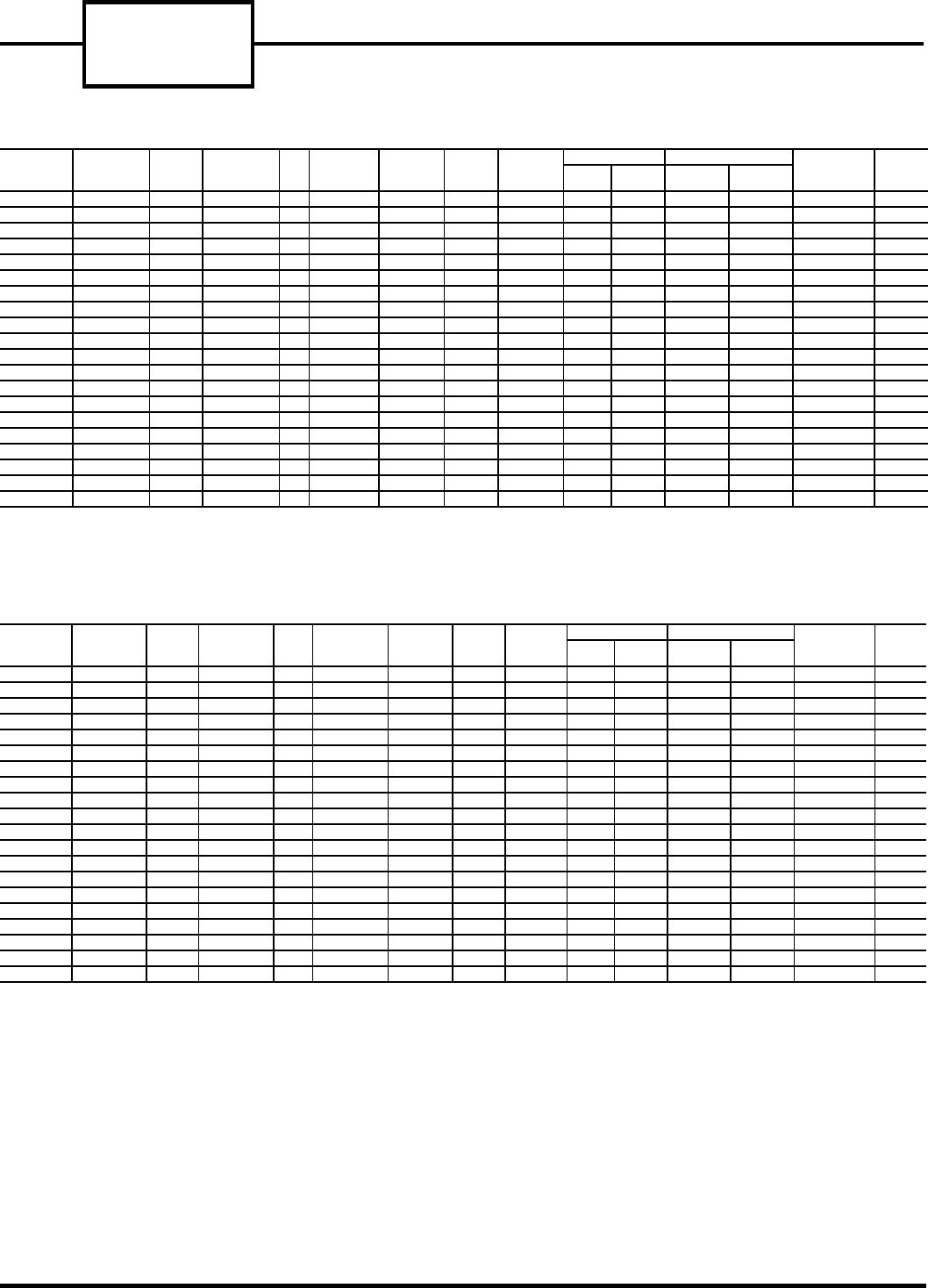
52C,P
SERIES
48
52C PERFORMANCE AND PHYSICAL DATA
FIGURE 73 — 52CE — PERFORMANCE AND PHYSICAL DATA FOR STANDARD HEAT/COOL UNITS
FIGURE 74 — 52CQ — PERFORMANCE AND PHYSICAL DATA FOR STANDARD HEAT PUMP UNITS
CATALOG
NUMBER
COOLING
(Btuh) EER ELECTRIC
HEAT (Btuh) COP
REVERSE
CYCLE
HEAT (Btuh)
EVAP. FAN
CFM
(HI-SPEED)
APPROX.
WEIGHT
(SHIP)
1-PH, 60 Hz
VOLTS
CURRENT (AMPS) INPUT POWER (WATTS) BRANCH
CIRCUIT FUSE
(AMPS)
R-22
CHARGE
(oz)
Cooling Electric
Heat Cooling Electric
Heat
52CE-207---3 7,000/ 6,900 11.1/11.1 7,800/ 6,400 —— 260/250 125 230/208 2.7/2.9 10.4/ 9.5 631/ 622 2393/1985 15 24
52CE-307---3 7,000/ 6,900 11.1/11.1 11,600/ 9,700 —— 260/250 125 230/208 2.7/2.9 15.2/14.1 631/ 622 3493/2935 20 24
52CE-209---3 9,000/ 8,900 10.7/10.7 7,800/ 6,400 —— 260/250 125 230/208 3.7/3.8 10.4/ 9.5 841/ 832 2393/1985 15 24
52CE-309---3 9,000/ 8,900 10.7/10.7 11,600/ 9,700 —— 260/250 125 230/208 3.7/3.8 15.2/14.1 841/ 832 3493/2935 20 24
52CE-212---3 12,000/11,900 10.1/10.1 7,800/ 6,400 —— 350/320 140 230/208 5.2/5.6 10.8/ 9.9 1188/1178 2470/2047 15 34
52CE-312---3 12,000/11,900 10.1/10.1 11,600/ 9,700 —— 350/320 140 230/208 5.2/5.6 15.6/14.5 1188/1178 3570/2997 20 34
52CE-512---3 12,000/11,900 10.1/10.1 17,000/13,600 —— 350/320 140 230/208 5.2/5.6 22.5/20.0 1188/1178 5170/4147 30 34
52CE-215---3 14,500/14,000 9.4/ 9.5 7,800/ 6,400 —— 350/320 150 230/208 6.8/7.6 10.9/10.0 1543/1473 2517/2117 15 35
52CE-315---3 14,500/14,000 9.4/ 9.5 11,600/ 9,700 —— 350/320 150 230/208 6.8/7.6 15.7/14.6 1543/1473 3617/3067 20 35
52CE-515---3 14,500/14,000 9.4/ 9.5 17,000/13,600 —— 350/320 150 230/208 6.8/7.6 22.6/20.1 1543/1473 5217/4217 30 35
52CE-207---4 7,000 11.1 7,800 —— 260 125 265 2.4 9.2 631 2396 15 26
52CE-307---4 7,000 11.1 11,600 —— 260 125 265 2.4 13.3 631 3496 20 26
52CE-209---4 8,900 10.7 7,800 —— 260 125 265 3.1 9.2 832 2396 15 24
52CE-309---4 8,900 10.7 11,600 —— 260 125 265 3.1 13.3 832 3496 20 24
52CE-212---4 12,000 10.1 7,800 —— 340 140 265 4.6 9.4 1188 2470 15 34
52CE-312---4 12,000 10.1 11,600 —— 340 140 265 4.6 13.5 1188 3570 20 34
52CE-512---4 12,000 10.1 17,000 —— 340 140 265 4.6 19.6 1188 5170 25 34
52CE-215---4 14,500 9.4 7,800 —— 340 150 265 6.0 9.7 1543 2517 15 36
52CE-315---4 14,500 9.4 11,600 —— 340 150 265 6.0 13.8 1543 3617 20 36
52CE-515---4 14,500 9.4 17,000 —— 340 150 265 6.0 19.9 1543 5217 25 36
CATALOG
NUMBER
COOLING
(Btuh) EER ELECTRIC
HEAT (Btuh) COP
REVERSE
CYCLE
HEAT (Btuh)
EVAP. FAN
CFM
(HI-SPEED)
APPROX.
WEIGHT
(SHIP)
1-PH, 60 Hz
VOLTS
CURRENT (AMPS) INPUT POWER (WATTS) BRANCH
CIRCUIT FUSE
(AMPS)
R-22
CHARGE
(oz)
Cooling Electric
Heat Cooling Electric
Heat
52CQ-207---3 7,000/ 6,900 11.1/11.1 7,800/ 6,400 3.1/3.1 6,100/ 6,000 260/250 125 230/208 2.7/2.9 10.4/ 9.5 631/ 622 2393/1985 15 24
52CQ-307---3 7,000/ 6,900 11.1/11.1 11,600/ 9,700 3.1/3.1 6,100/ 6,000 260/250 125 230/208 2.7/2.9 15.2/14.1 631/ 622 3493/2935 20 24
52CQ-209---3 9,000/ 8,900 10.7/10.7 7,800/ 6,400 3.1/3.1 7,900/ 7,800 260/250 125 230/208 3.7/3.8 10.4/ 9.5 841/ 832 2393/1985 15 24
52CQ-309---3 9,000/ 8,900 10.7/10.7 11,600/ 9,700 3.1/3.1 7,900/ 7,800 260/250 125 230/208 3.7/3.8 15.2/14.1 841/ 832 3493/2935 20 24
52CQ-212---3 12,000/11,900 10.1/10.1 7,800/ 6,400 3.0/3.0 10,800/10,700 350/320 140 230/208 4.7/5.2 10.8/ 9.9 1188/1178 2470/2047 15 34
52CQ-312---3 12,000/11,900 10.1/10.1 11,600/ 9,700 3.0/3.0 10,800/10,700 350/320 140 230/208 4.7/5.2 15.6/14.5 1188/1178 3570/2997 20 34
52CQ-512---3 12,000/11,900 10.1/10.1 17,000/13,600 3.0/3.0 10,800/10,700 350/320 140 230/208 4.7/5.2 22.5/20.0 1188/1178 5170/4147 30 34
52CQ-215---3 14,500/14,000 9.4/ 9.5 7,800/ 6,400 2.9/2.9 13,400/13,200 350/320 150 230/208 6.8/7.6 10.9/10.0 1543/1473 2517/2117 15 35
52CQ-315---3 14,500/14,000 9.4/ 9.5 11,600/ 9,700 2.9/2.9 13,400/13,200 350/320 150 230/208 6.8/7.6 15.7/14.6 1543/1473 3617/3067 20 35
52CQ-515---3 14,500/14,000 9.4/ 9.5 17,000/13,600 2.9/2.9 13,400/13,200 350/320 150 230/208 6.8/7.6 22.6/20.1 1543/1473 5217/4217 30 35
52CQ-207---4 7,000 11.1 7,800 3.1 6,100 260 125 265 2.4 9.2 631 2396 15 26
52CQ-307---4 7,000 11.1 11,600 3.1 6,100 260 125 265 2.4 13.3 631 3496 20 26
52CQ-209---4 8,900 10.7 7,800 3.1 7,700 260 125 265 3.1 9.2 832 2396 15 24
52CQ-309---4 8,900 10.7 11,600 3.1 7,700 260 125 265 3.1 13.3 832 3496 20 24
52CQ-212---4 12,000 10.1 7,800 3.0 10,800 340 140 265 4.5 9.4 1188 2470 15 34
52CQ-312---4 12,000 10.1 11,600 3.0 10,800 340 140 265 4.5 13.5 1188 3570 20 34
52CQ-512---4 12,000 10.1 17,000 3.0 10,800 340 140 265 4.5 19.6 1188 5170 25 34
52CQ-215---4 14,500 9.4 7,800 2.9 13,400 340 150 265 6.0 9.7 1543 2517 15 36
52CQ-315---4 14,500 9.4 11,600 2.9 13,400 340 150 265 6.0 13.8 1543 3617 20 36
52CQ-515---4 14,500 9.4 17,000 2.9 13,400 340 150 265 6.0 19.9 1543 5217 25 36
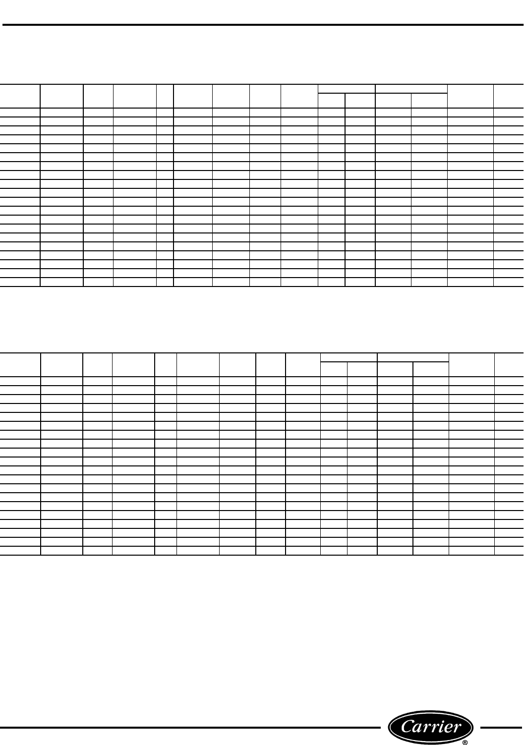
49
52P PERFORMANCE AND PHYSICAL DATA
FIGURE 75 — 52PE — PERFORMANCE AND PHYSICAL DATA FOR STANDARD HEAT/COOL UNITS
FIGURE 76 — 52PQ — PERFORMANCE AND PHYSICAL DATA FOR STANDARD HEAT PUMP UNITS
CATALOG
NUMBER
COOLING
(Btuh) EER ELECTRIC
HEAT (Btuh) COP
REVERSE
CYCLE
HEAT (Btuh)
EVAP. FAN
CFM
(HI-SPEED)
APPROX.
WEIGHT
(SHIP)
1-PH, 60 Hz
VOLTS
CURRENT (AMPS) INPUT POWER (WATTS) BRANCH
CIRCUIT FUSE
(AMPS)
R-22
CHARGE
(oz)
Cooling Electric
Heat Cooling Electric
Heat
52PE-207---3 7,200/ 7,100 12.7/12.7 7,800/ 6,400 —— 260/250 125 230/208 2.7/2.9 10.4/ 9.5 567/ 559 2393/1985 15 24
52PE-307---3 7,200/ 7,100 12.7/12.7 11,600/ 9,700 —— 260/250 125 230/208 2.7/2.9 15.2/14.1 567/ 559 3493/2935 20 24
52PE-209---3 9,100/ 9,000 11.5/11.5 7,800/ 6,400 —— 260/250 125 230/208 3.7/3.8 10.4/ 9.5 791/ 783 2393/1985 15 24
52PE-309---3 9,100/ 9,000 11.5/11.5 11,600/ 9,700 —— 260/250 125 230/208 3.7/3.8 15.2/14.1 791/ 783 3493/2935 20 24
52PE-212---3 12,100/12,000 11.1/10.7 7,800/ 6,400 —— 350/320 140 230/208 4.8/5.3 10.8/ 9.9 1090/1122 2470/2047 15 34
52PE-312---3 12,100/12,000 11.1/10.7 11,600/ 9,700 —— 350/320 140 230/208 4.8/5.3 15.6/14.5 1090/1122 3570/2997 20 34
52PE-512---3 12,100/12,000 11.1/10.7 17,000/13,600 —— 350/320 140 230/208 4.8/5.3 22.5/20.0 1090/1122 5170/4147 30 34
52PE-215---3 14,500/14,000 9.4/ 9.5 7,800/ 6,400 —— 350/320 150 230/208 6.8/7.6 10.9/10.0 1543/1473 2517/2117 15 35
52PE-315---3 14,500/14,000 9.4/ 9.5 11,600/ 9,700 —— 350/320 150 230/208 6.8/7.6 15.7/14.6 1543/1473 3617/3067 20 35
52PE-515---3 14,500/14,000 9.4/ 9.5 17,000/13,600 —— 350/320 150 230/208 6.8/7.6 22.6/20.1 1543/1473 5217/4217 30 35
52PE-207---4 7,200 12.7 7,800 —— 260 125 265 2.4 9.2 567 2396 15 26
52PE-307---4 7,200 12.7 11,600 —— 260 125 265 2.4 13.3 567 3496 20 26
52PE-209---4 9,100 11.5 7,800 —— 260 125 265 3.1 9.2 791 2396 15 24
52PE-309---4 9,100 11.5 11,600 —— 260 125 265 3.1 13.3 791 3496 20 24
52PE-212---4 12,100 11.1 7,800 —— 340 140 265 4.2 9.4 1090 2470 15 34
52PE-312---4 12,100 11.1 11,600 —— 340 140 265 4.2 13.5 1090 3570 20 34
52PE-512---4 12,100 11.1 17,000 —— 340 140 265 4.2 19.6 1090 5170 25 34
52PE-215---4 14,500 9.4 7,800 —— 340 150 265 6.0 9.7 1543 2517 15 36
52PE-315---4 14,500 9.4 11,600 —— 340 150 265 6.0 13.8 1543 3617 20 36
52PE-515---4 14,500 9.4 17,000 —— 340 150 265 6.0 19.9 1543 5217 25 36
CATALOG
NUMBER
COOLING
(Btuh) EER ELECTRIC
HEAT (Btuh) COP
REVERSE
CYCLE
HEAT (Btuh)
EVAP. FAN
CFM
(HI-SPEED)
APPROX.
WEIGHT
(SHIP)
1-PH, 60 Hz
VOLTS
CURRENT (AMPS) INPUT POWER (WATTS) BRANCH
CIRCUIT FUSE
(AMPS)
R-22
CHARGE
(oz)
Cooling Electric
Heat Cooling Electric
Heat
52PQ-207---3 7,200/ 7,100 12.7/12.7 7,800/ 6,400 3.4/3.4 6,300/ 6,300 260/250 125 230/208 2.7/2.9 10.4/ 9.5 567/ 559 2393/1985 15 24
52PQ-307---3 7,200/ 7,100 12.7/12.7 11,600/ 9,700 3.4/3.4 6,300/ 6,300 260/250 125 230/208 2.7/2.9 15.2/14.1 567/ 559 3493/2935 20 24
52PQ-209---3 9,100/ 9,000 11.5/11.5 7,800/ 6,400 3.2/3.2 7,900/ 7,900 260/250 125 230/208 3.7/3.8 10.4/ 9.5 791/ 783 2393/1985 15 24
52PQ-309---3 9,100/ 9,000 11.5/11.5 11,600/ 9,700 3.2/3.2 7,900/ 7,900 260/250 125 230/208 3.7/3.8 15.2/14.1 791/ 783 3493/2935 20 24
52PQ-212---3 12,100/12,000 11.1/10.7 7,800/ 6,400 3.2/3.2 11,000/11,000 350/320 140 230/208 4.8/5.3 10.8/ 9.9 1090/1122 2470/2047 15 34
52PQ-312---3 12,100/12,000 11.1/10.7 11,600/ 9,700 3.2/3.2 11,000/11,000 350/320 140 230/208 4.8/5.3 15.6/14.5 1090/1122 3570/2997 20 34
52PQ-512---3 12,100/12,000 11.1/10.7 17,000/13,600 3.2/3.2 11,000/11,000 350/320 140 230/208 4.8/5.3 22.5/20.0 1090/1122 5170/4147 30 34
52PQ-215---3 14,500/14,000 9.4/ 9.5 7,800/ 6,400 2.9/2.9 13,400/13,200 350/320 150 230/208 6.8/7.6 10.9/10.0 1543/1473 2517/2117 15 35
52PQ-315---3 14,500/14,000 9.4/ 9.5 11,600/ 9,700 2.9/2.9 13,400/13,200 350/320 150 230/208 6.8/7.6 15.7/14.6 1543/1473 3617/3067 20 35
52PQ-515---3 14,500/14,000 9.4/ 9.5 17,000/13,600 2.9/2.9 13,400/13,200 350/320 150 230/208 6.8/7.6 22.6/20.1 1543/1473 5217/4217 30 35
52PQ-207---4 7,200 12.7 7,800 3.4 6,300 260 125 265 2.4 9.2 567 2396 15 26
52PQ-307---4 7,200 12.7 11,600 3.4 6,300 260 125 265 2.4 13.3 567 3496 20 26
52PQ-209---4 9,100 11.5 7,800 3.2 7,700 260 125 265 3.1 9.2 791 2396 15 24
52PQ-309---4 9,100 11.5 11,600 3.2 7,700 260 125 265 3.1 13.3 791 3496 20 24
52PQ-212---4 12,100 11.1 7,800 3.2 10,800 340 140 265 4.2 9.4 1090 2470 15 34
52PQ-312---4 12,100 11.1 11,600 3.2 10,800 340 140 265 4.2 13.5 1090 3570 20 34
52PQ-512---4 12,100 11.1 17,000 3.2 10,800 340 140 265 4.2 19.6 1090 5170 25 34
52PQ-215---4 14,500 9.4 7,800 2.9 13,400 340 150 265 6.0 9.7 1543 2517 15 36
52PQ-315---4 14,500 9.4 11,600 2.9 13,400 340 150 265 6.0 13.8 1543 3617 20 36
52PQ-515---4 14,500 9.4 17,000 2.9 13,400 340 150 265 6.0 19.9 1543 5217 25 36

Copyright 2002 Carrier Corporation
Manufacturer reserves the right to discontinue, or change at any time, specifications or designs without notice and without incurring obligations.
PC 132 Catalog No. 535-20050 Printed in U.S.A. Form 52C,P-2SM Pg 52 11-02 Replaces: 52C,P-1SM
Book 1 4
Tab 9a 11a
