Carrier 62Mb Users Manual
62MD 62m-1si
62MD to the manual 11728cc6-bf0b-4b88-97a7-2aae092214b9
2015-01-24
: Carrier Carrier-62Mb-Users-Manual-311079 carrier-62mb-users-manual-311079 carrier pdf
Open the PDF directly: View PDF ![]() .
.
Page Count: 82
Manufacturer reserves the right to discontinue, or change at any time, specifications or designs without notice and without incurring obligations.
Catalog No. 536-220 Printed in U.S.A. Form 62M-1SI Pg 1 1-06 Replaces: New
Book 1 4
Tab 10a 12a
Installation, Start-Up and
Service Instructions
CONTENTS
Page
SAFETY CONSIDERATIONS .......................1
INTRODUCTION...................................1
INSTALLATION ................................ 1-58
Step 1 — Inspection ...............................1
Step 2 — Install Roof Curb ........................1
• STAND-ALONE APPLICATIONS
• COUPLED APPLICATIONS
Step 3 — Rigging and Handling .................45
• MOUNTING THE UNIT INDOORS
Step 4 — Installing ERV Transitions ...............47
• ERV UNIT COUPLED WITH A 3 TO 12 1/2TON
HVAC UNIT
Step 5 — Make Electrical Connections ............47
• POWER SUPPLY
• ELECTRICAL CONNECTIONS
START-UP .................................... 59-75
Unit Preparation .................................59
Internal Wiring ..................................59
Rain Hoods .....................................59
Energy Recovery Wheel .........................59
•DRIVEBELT
•AIRSEALS
Blower Rotation .................................59
Airflow Settings and Adjustments...............59
• FACTORY SETTING
• CURVE SELECTION
• ADJUST THE ERV BLOWER SPEED
• MEASURE MOTOR VOLTAGE, AMPERAGE
AND FAN RPM
• BELT MAINTENANCE
Variable Air Volume Option......................74
Operating Sequence ............................74
• OCCUPIED MODE
• UNOCCUPIED MODE
SERVICE ..................................... 75-78
Removing Wheel Segments for Cleaning
(62M170-950 Units)............................75
Removing and Installing Non-Segmented
Wheel for Cleaning (62M040 Units)............75
Removing and Installing Non-Segmented
Wheel for Cleaning (62M075,120 Units) .......76
Installing Wheel Segments (62M170-950 Units)...76
Wheel Drive Motor and Pulley Replacement .....77
Belt Replacement ...............................77
MAINTENANCE ...............................78,79
START UP CHECKLIST ........................CL-1
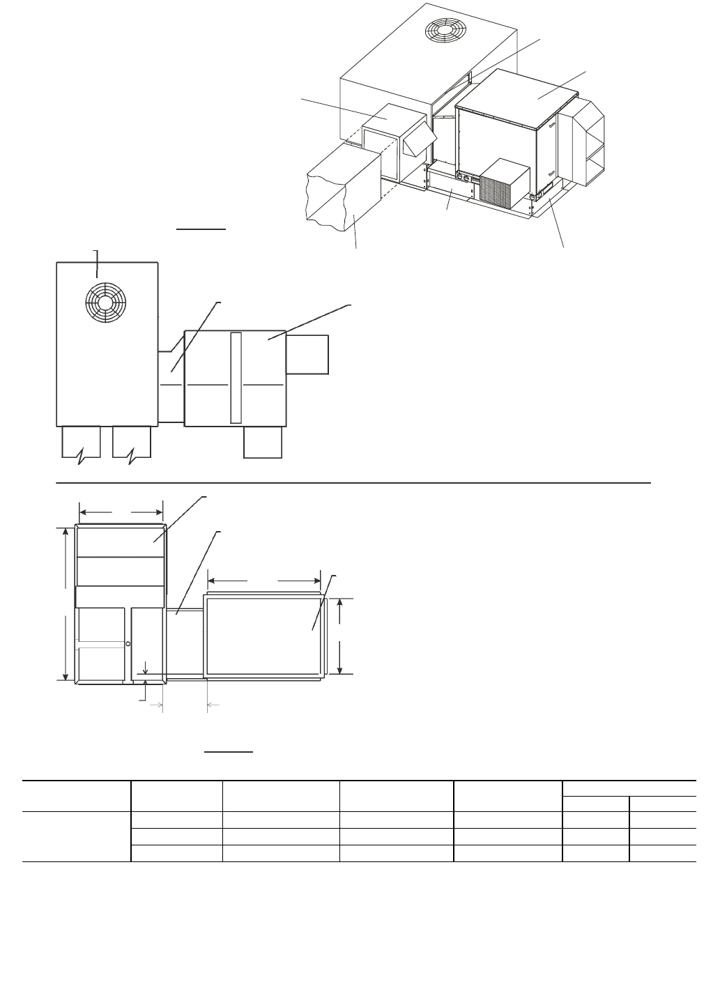
SAFETY CONSIDERATIONS
Installation and servicing of air-conditioning equipment can
be hazardous due to system pressure and electrical compo-
nents. Only trained and qualified service personnel should
install, repair, or service air-conditioning equipment.
Untrained personnel can perform the basic maintenance
functions of cleaning coils and filters and replacing filters. All
other operations should be performed by trained service
personnel. When working on air-conditioning equipment,
observe precautions in the literature, tags and labels attached to
the unit, and other safety precautions that may apply.
Follow all safety codes. Wear safety glasses and work
gloves. These instructions describe how to install, start up, and
service 62M energy recovery ventilator units.
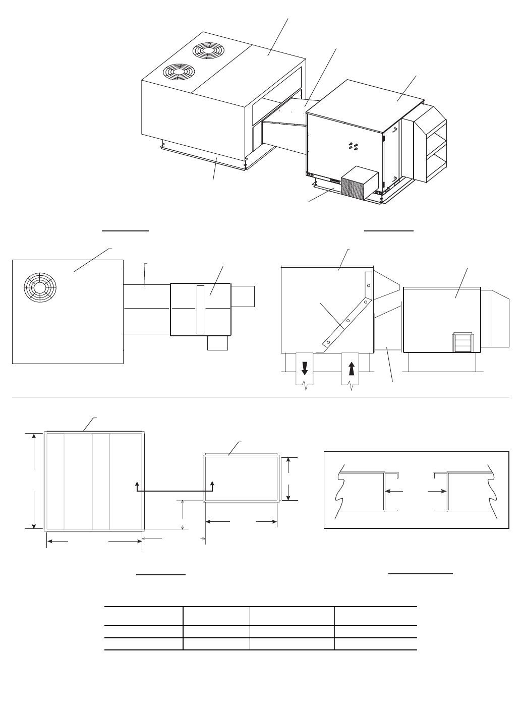
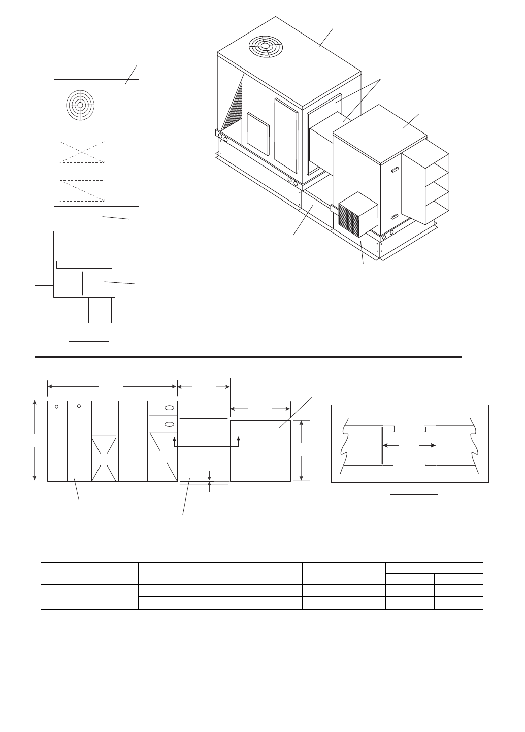
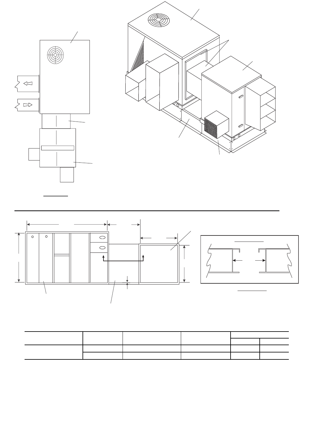
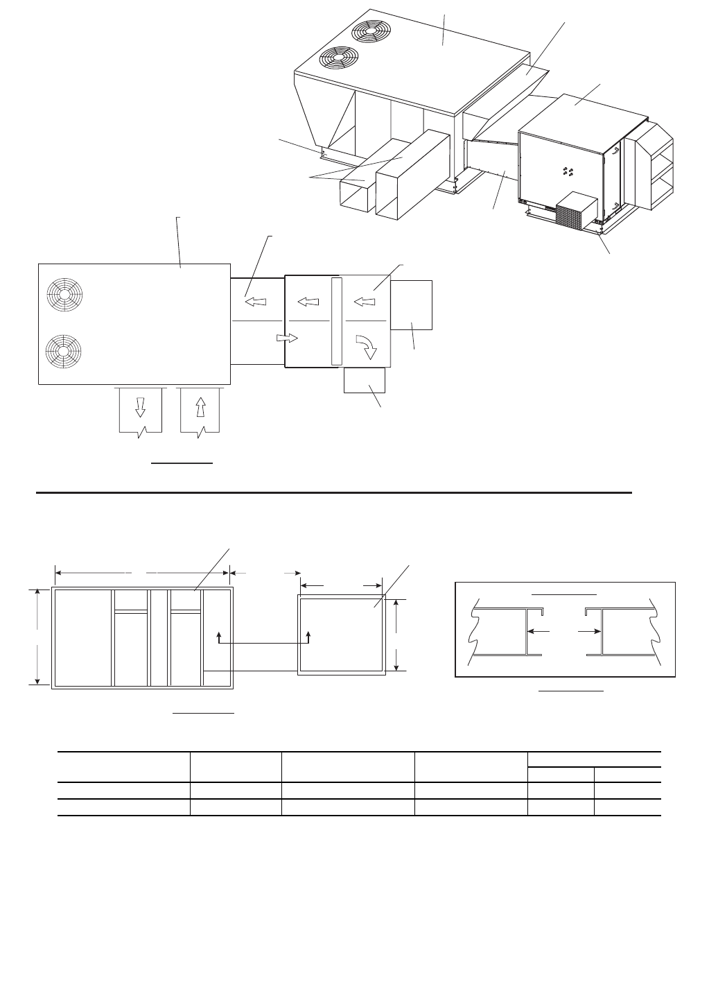
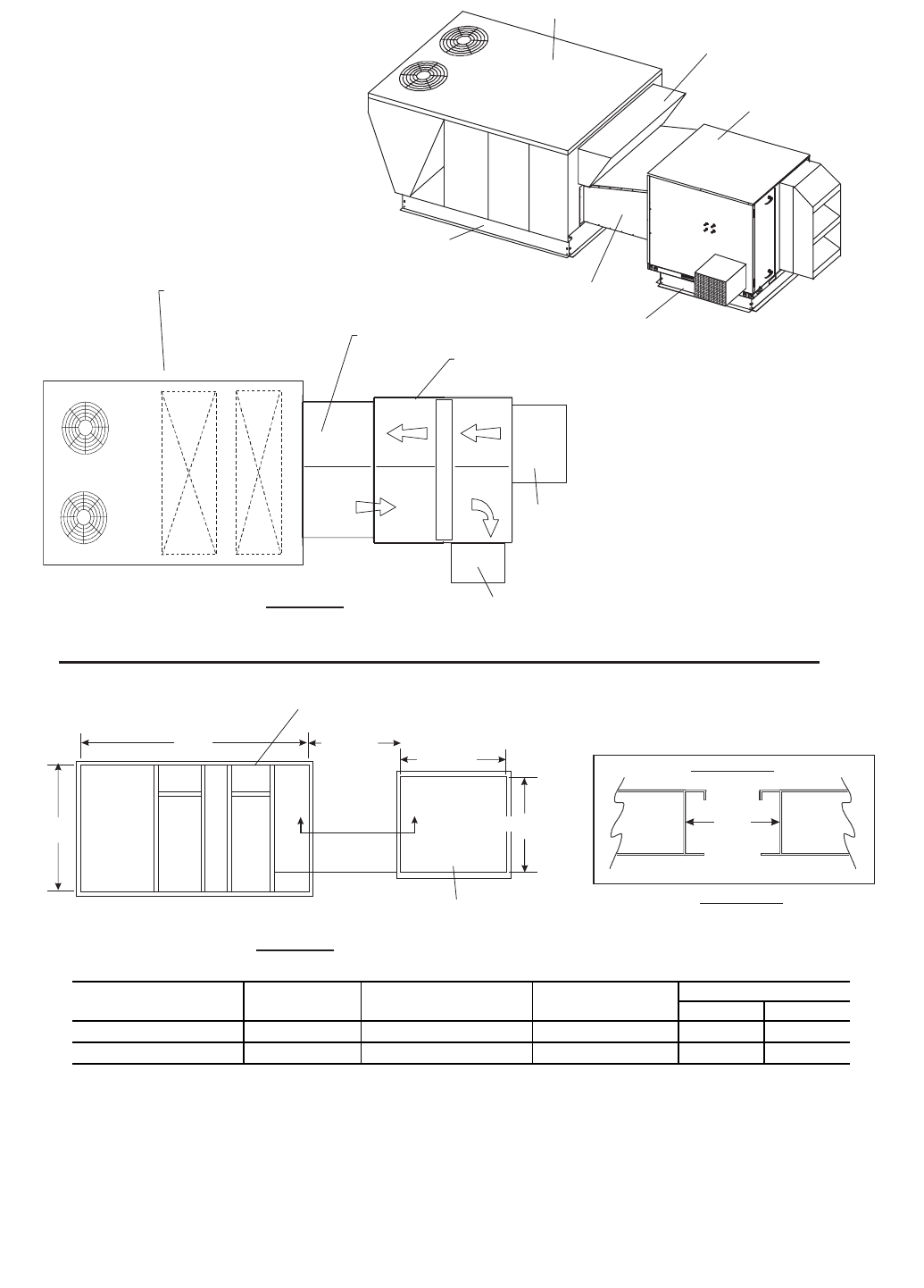
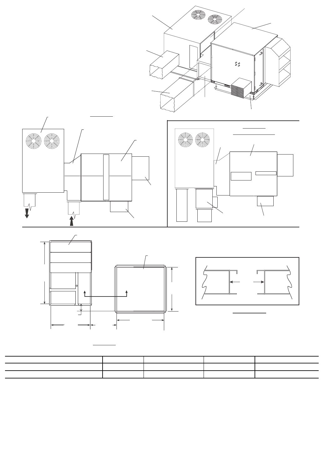
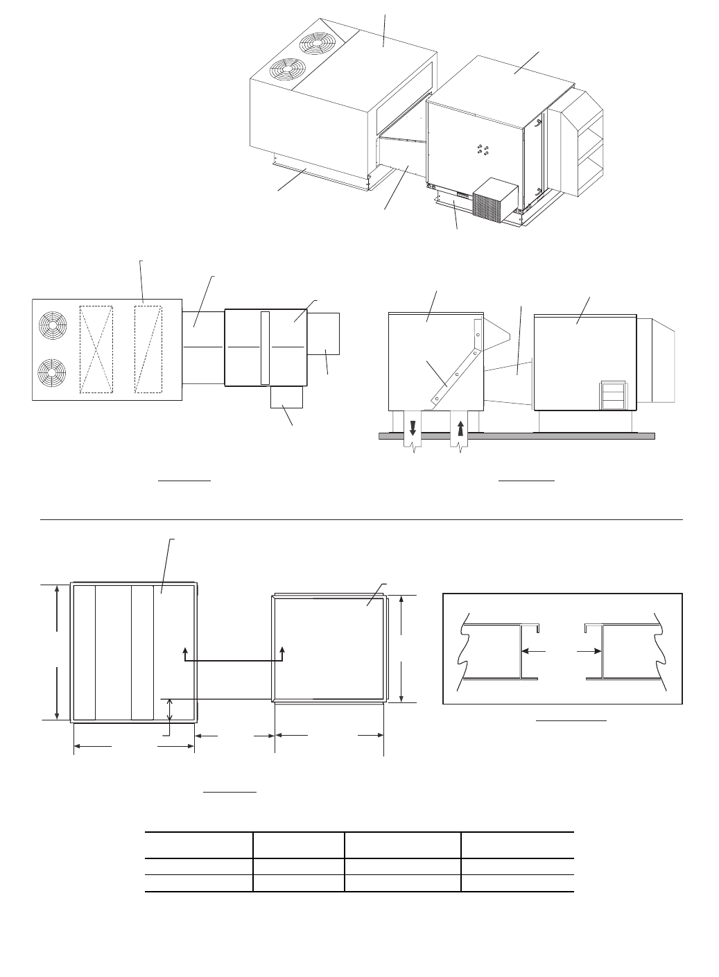
INTRODUCTION
The 62M energy recovery ventilator (ERV) units recover
energy from building exhaust air and pre-condition ventilation
air. All ERV units are available in either vertical discharge
(through the bottom) or horizontal discharge configuration.
The 62MB and MC vertical discharge units are used when a
stand-alone ERV unit is required.
The 62MD and ME horizontal discharge unit can be used as
a stand-alone unit, or can also be coupled with a Carrier rooftop
unit.
INSTALLATION
Step 1 — Inspection — Inspect the unit; file a claim
with the shipping company if the unit is damaged. Check the
packing list to ensure that the correct items have been received
and notify your Carrier representative of any discrepancy.
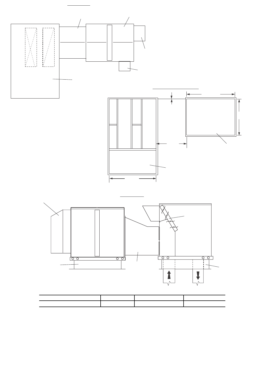
Step 2 — Install Roof Curb
STAND-ALONE APPLICATIONS — The ERV unit can be
installed without being coupled with a Carrier rooftop unit. The
ERV units can be installed in one of three stand-alone applica-
tions: down discharge, horizontal discharge, or a combination
of both down discharge and horizontal discharge.
When installing a stand-alone ERV unit refer to Fig. 1-45
and, complete the following:
Locate the Roof Curb — Prior to locating the roof curb con-
sider the structural support required for the rooftop system and,
the duct drop location in relation to the joists. Allow sufficient
space for service, clearance, and locations of vents or other
sources of air.
Electrical shock can cause personal injury and death. Shut
off all power to this equipment during installation. There
may be more than one disconnect switch. Tag all discon-
nect locations to alert others not to restore power until work
is completed.
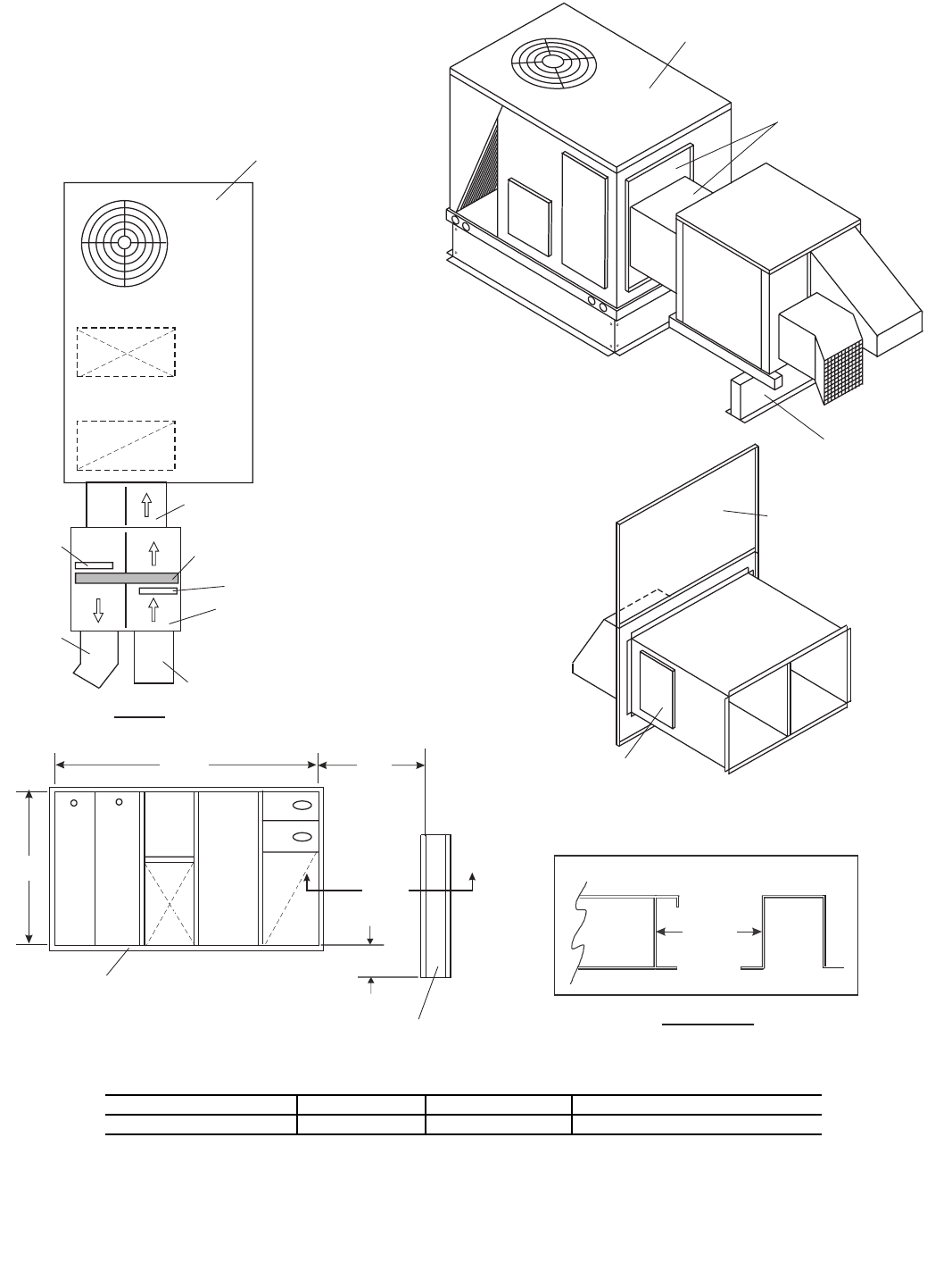
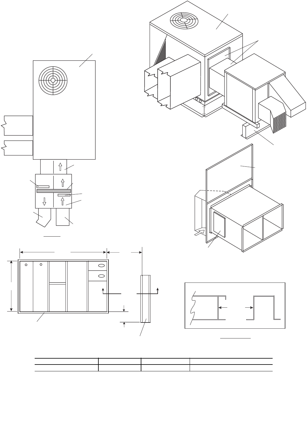
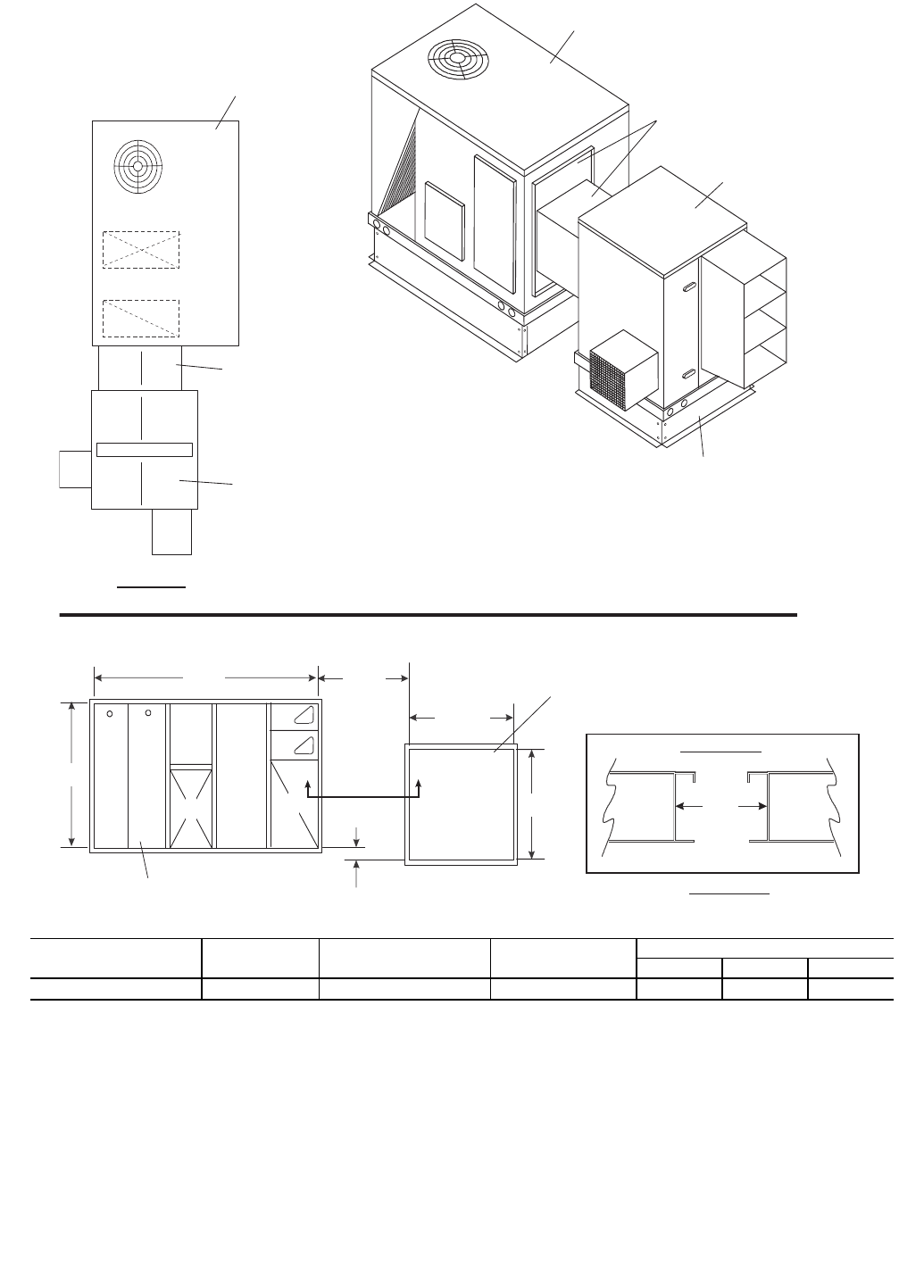
62MB,MC,MD,ME040-950
Energy Recovery
Ventilators
2
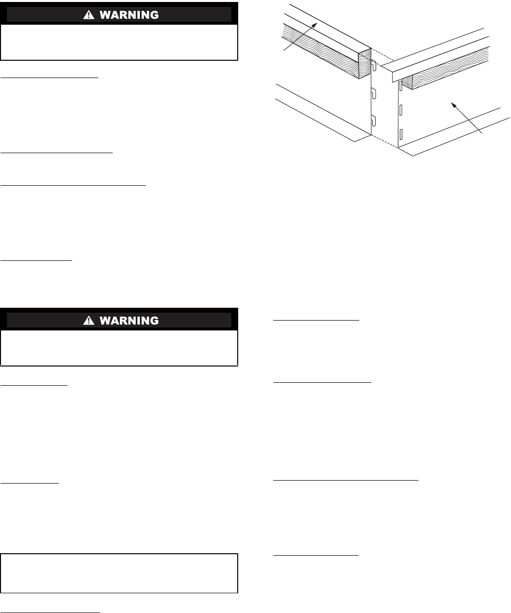
Assemble the Roof Curb — Connect the curb side and the
curb end. See Fig. 1. Insert the tabs on the curb end into the
slots on the curb sides. Press firmly until the pieces lock into
place. It may be necessary to exert additional force to the top of
the curb to lock the pieces in place. Ensure the curb pieces are
locked together prior to proceeding.
Repeat for all corners of the roof curb.
Prepare Roof Curb Location — Cut a hole in the roof for duct
openings. See Fig. 2-5 for duct opening dimensions. Frame the
opening to provide adequate structural support.
Install Deck Pans and Duct Supports — The roof curb may
have a duct support and deck pans, depending on the model
and application. Determine which end of the roof curb will be
the duct end.
Install the deck pans on the roof curb with the insulation
side facing up toward the ERV base. Install the duct support
between the supply and return openings.
Set the Roof Curb — Fit the roof curb assembly by measuring
across the corners of the curb to ensure a square fit. Set the roof
curb over the roof opening. Level the curb by placing shims
under the bottom flange of the curb. Secure the curb in place by
welding or fastening the curb to the roof.
Install Ductwork — Ductwork will be installed in the roof
curb for vertical discharge and stand-alone applications. The
duct will hang from the top of the curb. See Fig. 45 for stand-
alone application airflow.
NOTE: Ductwork must be installed before the ERV unit is set
in place.
Refer to Fig. 2-5 to determine the duct size required.
Provide field manufactured duct and place into the supply and
return openings in the curb.
Install Gaskets — The ERV roof curbs come with a gasketing
package to provide a seal between the ERV unit and the top
perimeter of the roof curb. Install the gasket around the top
perimeter of the curb and around the supply and return opening.
NOTE: Some stand-alone curbs will not have duct openings).
Gasket strips must fit tightly together, leaving no gaps for
leakage.
Install Roofing Materials — Insulate and add a cant strip to
the roof curb. Follow suggested and acceptable roofing practices
for applying roofing materials. The roofing material should
extend up to the wood nailer and be secured under the counter-
flashing. Follow all local, national, and industry roofing
standards. Refer to Fig. 6 for roofing recommendations.
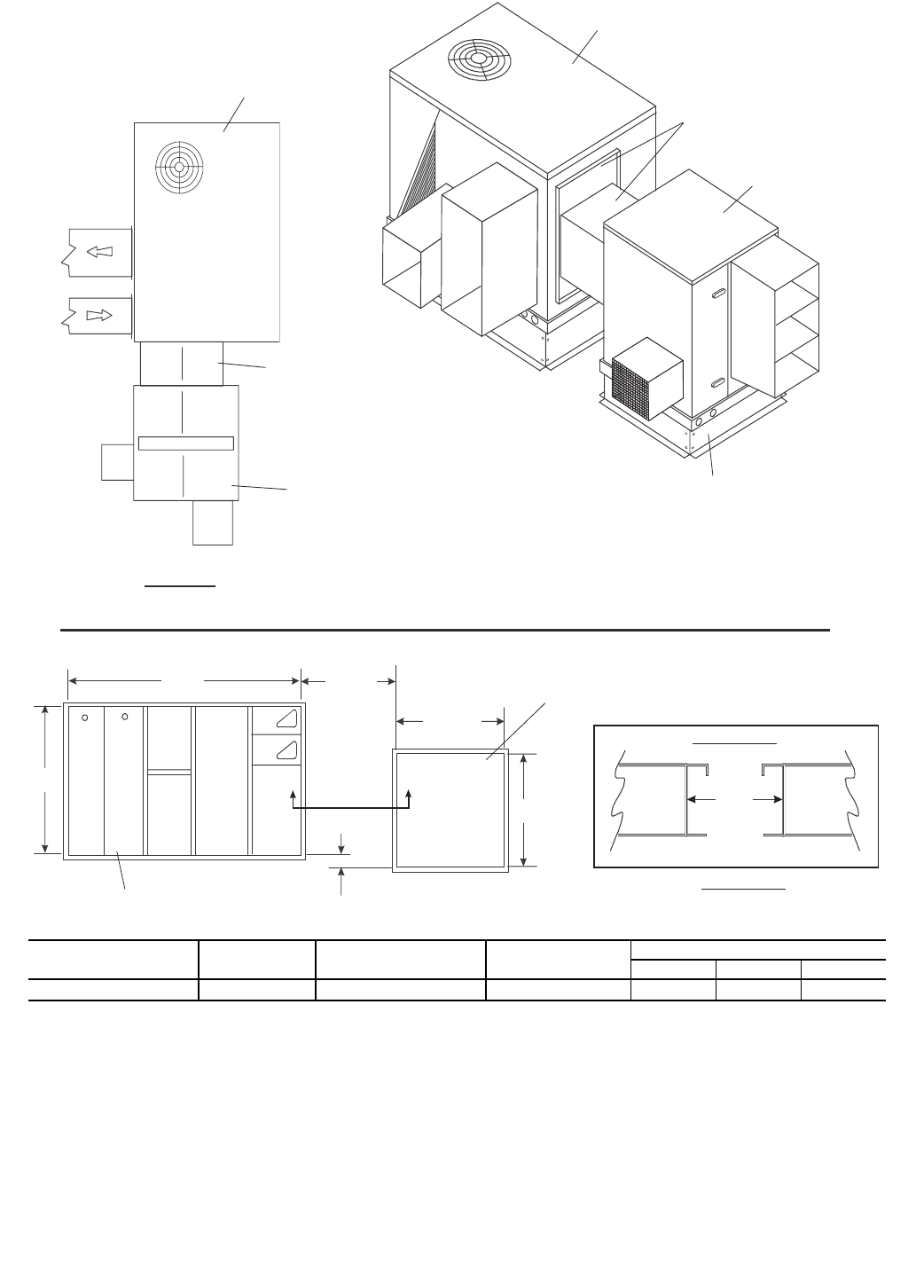
COUPLED APPLICATIONS — The ERV unit can be in-
stalled directly coupled to a Carrier rooftop unit. The connec-
tion between the ERV and HVAC (Heating, Ventilation, and
Air Conditioning) unit is made with the use of a transition. In a
coupled rooftop application there is a separate roof curb for the
HVAC curb and a separate roof curb for the ERV unit. See
Fig. 4 and 5 for roof curb dimensions.
Locate the Roof Curb — Prior to locating the roof curb con-
sider the structural support required for the rooftop system and,
the duct drop location in relation to the joists. Allow sufficient
space for service, clearance, and locations of vents or other
sources of air. Refer to the rooftop installation instructions for
more information regarding location considerations.
Assemble the Roof Curb — Connect the curb side and the
curb end. Insert the tabs on the curb end into the slots on the
curb sides. Press firmly until the pieces lock in to place. It may
be necessary to exert additional force to the top of the curb to
lock the pieces in place. Ensure the curb pieces are locked to-
gether prior to proceeding.
Repeat for other corners of the roof curb.
NOTE: If lifting or moving the roof curb assembly hammer
the tabs over 90 degrees.
Install Deck Pans and Duct Supports — The roof curb may
have a duct support and deck pans, depending on the model
and application. Refer to Fig. 2-5. Determine which end of the
roof curb will be the duct end.
Install the deck pans on the roof curb with the insulation
side facing up toward the ERV base. Install the duct support
between the supply and return openings.
Install Locator Pieces — Some ERV roof curbs (62MA-CRB-
14MC and 62MB-CRB-14MC) will include locator pieces,
which are to be attached to the ERV roof curb section. The
locator pieces will help the installer ensure that the ERV and
HVAC unit roof curbs are positioned properly. Attach the
2 side locator pieces to the ERV roof curb. Install the cover
panel over the 2 sides and fasten in place.
Cover roof opening if installation of the ERV unit will not
be immediate. Failure to cover roof opening could result in
water damage and/or serious personal injury.
Cover the roof curb if installation of the ERV unit will not
be immediate. Failure to cover the roof curb could result in
water damage and/or serious personal injury.
IMPORTANT: Gasket installation is critical for water
integrity. Improperly installed gaskets can result in air
or water leaks, leading to poor unit performance.
END
SIDE
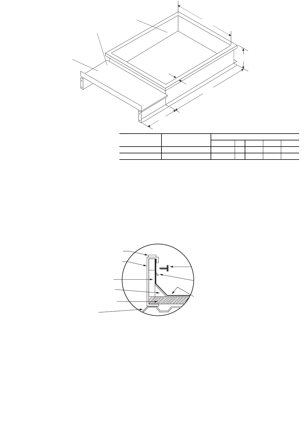
Fig. 1 — Assembling the Roof Curb
3
Set the Roof Curb — Fit the roof curb assembly by measuring
across the corners of the curb to ensure a square fit. Set the roof
curb over the roof opening. Level the curb by placing shims
under the bottom flange of the curb. Secure the curb in place by
welding or fastening the curb to the roof.
Install Ductwork — Ductwork will be installed in the roof
curb for vertical, coupled applications. The duct will hang from
the top of the curb.
NOTE: Ductwork must be installed before the rooftop unit is
set in place.
NOTE: Ductwork must be installed before the ERV unit is set
in place.
Refer to Fig. 2 and 3 to determine the duct size required.
Provide field manufactured duct and place into the supply and
return openings in the curb.
Install Gaskets — The ERV roof curbs come with a gasketing
package to provide a seal between the ERV unit and the top
perimeter of the roof curb. Install the gasket around the top
perimeter of the curb and around the supply and return
opening. (Some stand-alone curbs will not have duct open-
ings.) Gasket strips must fit tightly together, leaving no gaps for
leakage.
Install Roofing Materials — Insulate and add a cant strip to
the roof curb. Follow suggested and acceptable roofing proce-
dures for applying roofing materials. The roofing material
should extend up to the wood nailer and be secured under the
counter flashing. Follow all local, national, and industry roof-
ing standards. Refer to Fig. 5 for roofing recommendations.
IMPORTANT: The ERV roof curb must be set in
precisely the correct location relative to the rooftop
roof curb for the transitions to connect properly. See
Fig. 7-44 for location dimensions.
IMPORTANT: Gasket installation is critical for water
integrity. Improperly installed gaskets can result in air
or water leaks, leading to poor unit performance.
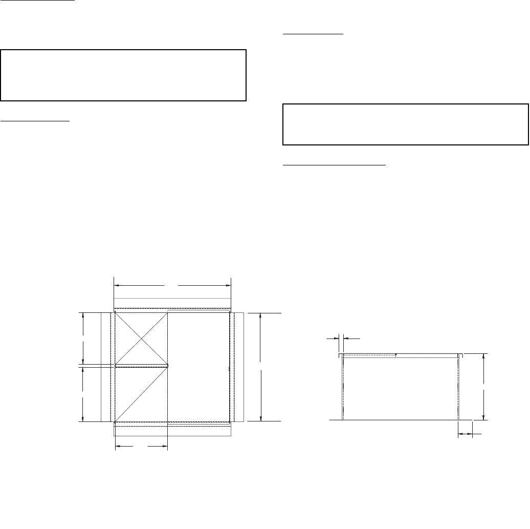
10.81
11.00
11.50
RETURN
SUPPLY
14.00
1.00
TYP. 4X
3.00
TYP. 4X
24.09
22.94
NOTES:
1. All dimensions are in inches.
2. Roof curb shipped unassembled.
Fig. 2 — Roof Curb — 62M040 for Stand-Alone Applications
4
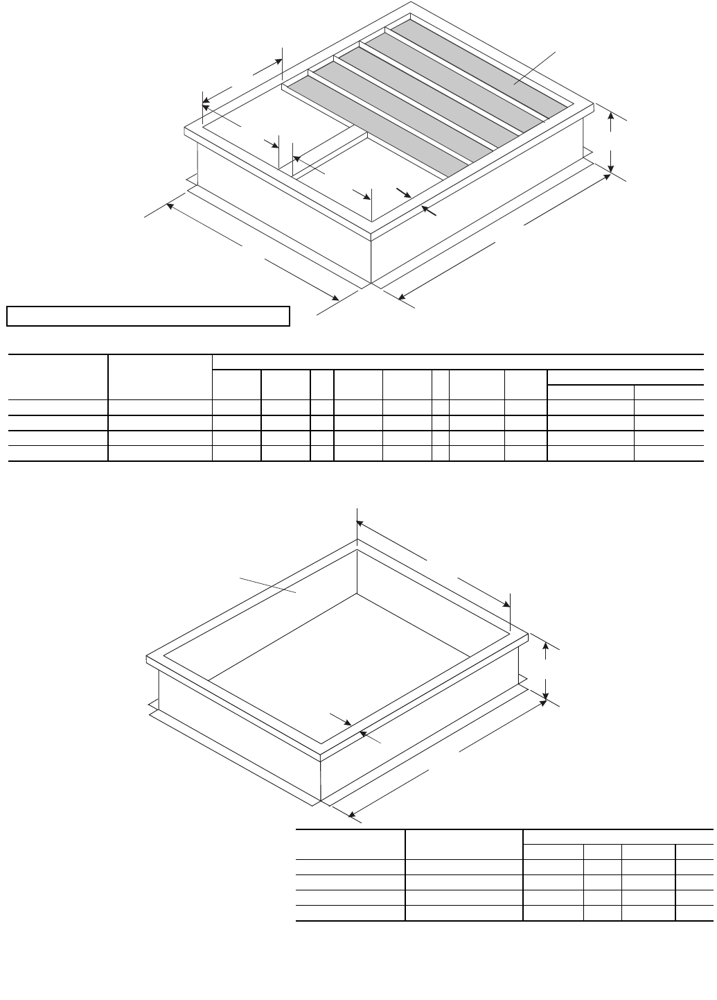
C
D
G
EF
B
A
R/A
S/A
Typical Insulated deck pans.
(Insulation face up) *
H
62M UNIT SIZE CURB
PART NO.
DIMENSIONS (in.)
ABCDEFGH Duct Sizes
Return Supply
075,120 62M-A-CRB-14S 27 30.5 14 14 11.3 1 14.7 1.5 13.75 x 14.38 13.75 x 11
170-285 62M-B-CRB-14S 45.5 49.63 14 17.5 19.5 2 24 1.75 17 x 23.5 17 x 19
330-640 62M-C-CRB-14S 55.41 60.34 14 24.84 23.41 2 30 — 24.5 x 29.5 24.5 x 23
750,950 62M-D-CRB-14S 86.25 95.7 14 32.5 42.13 2 42.13 — 32 x 41.75 32 x 41.75
LEGEND
NOTE: Roof curb shipped unassembled.
R/A — Return Air
S/A — Supply Air
*IMPORTANT: Insulation on deck pans must face up.
Fig. 3 — Roof Curb — 62M075-950 for Vertical Stand-Alone Applications
ERV Curb
C
B
A
D
*62M075,120 curb is shipped with deckpans insulation and duct supports which may
be discarded.
†62M170-285 curb is shipped with deck pans and insulation.
62M UNIT SIZE CURB
PART NO.
DIMENSIONS (in.)
A BCD
075,120* 62M-A-CRB-14S 27 30.5 14 1.5
170-285† 62M-B-CRB-14S 49.63 14 45.5 1.75
330-640 62M-C-CRB-14M 60.34 14 55.41 1.75
750,950 62M-D-CRB-14M 95.7 14 86.25 1.75
LEGEND
NOTE: Roof curb shipped unassembled.
ERV — Energy Recovery Ventilator
Fig. 4 — Roof Curb — 62M075-950 for Horizontal Stand-Alone Applications
or Units Coupled with Rooftop Units 15 Tons and Above
5
ERV Curb
Locator pieces to connect
ERV curb to rooftop unit curb
C
B
A
D
E
Must be Watertight
NAIL*
FLASHING*
ROOF FELT*
ROOF*
ROOF DECK*
CANT STRIP*
RIGID
INSULATION*
GASKETING
ROOF CURB
62M UNIT SIZE CURB
PART NO.
DIMENSIONS (in.)
ABC D E
075,120 62M-A-CRB-14MC 30.5 14 27 1.5 19.81
170-285 62M-B-CRB-14MC 49.63 14 45.5 1.75 37.81
LEGEND
NOTE: Roof curb shipped unassembled.
ERV — Energy Recovery Ventilator
Fig. 5 — Roof Curb — 62M075-285 Units 3 to 121/2Ton Rooftop Units
*Field provided.
Fig. 6 — Roofing Materials — Recommendation
6
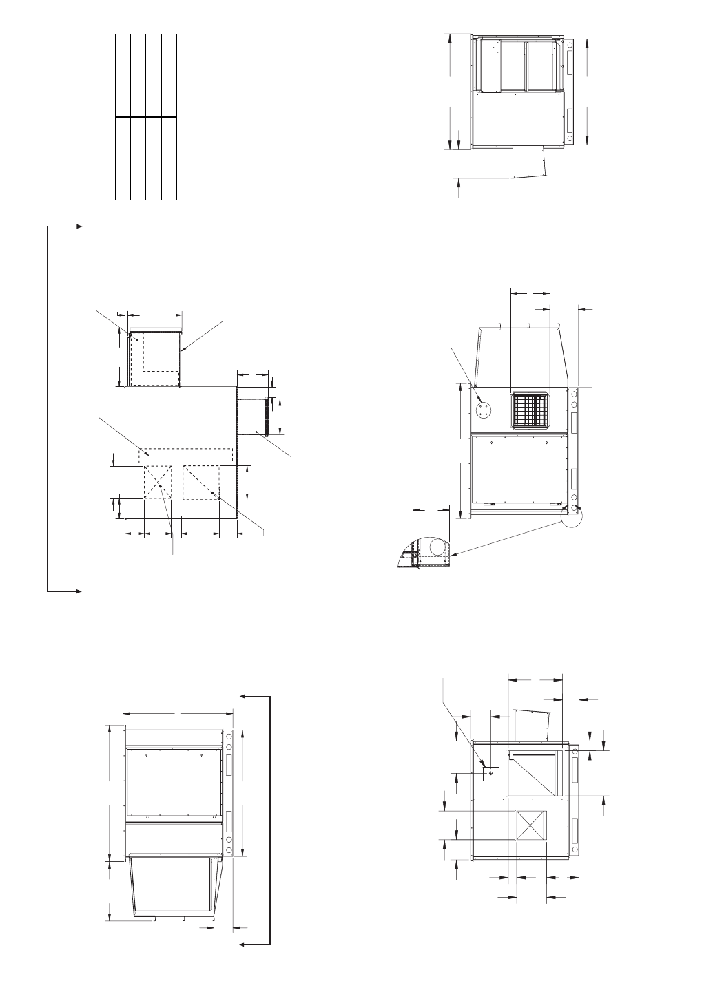
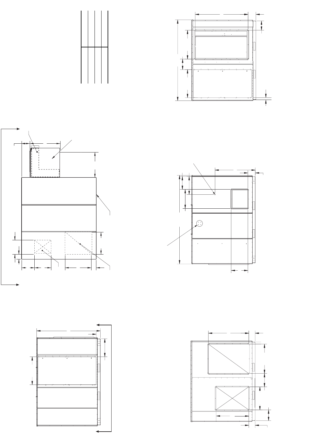
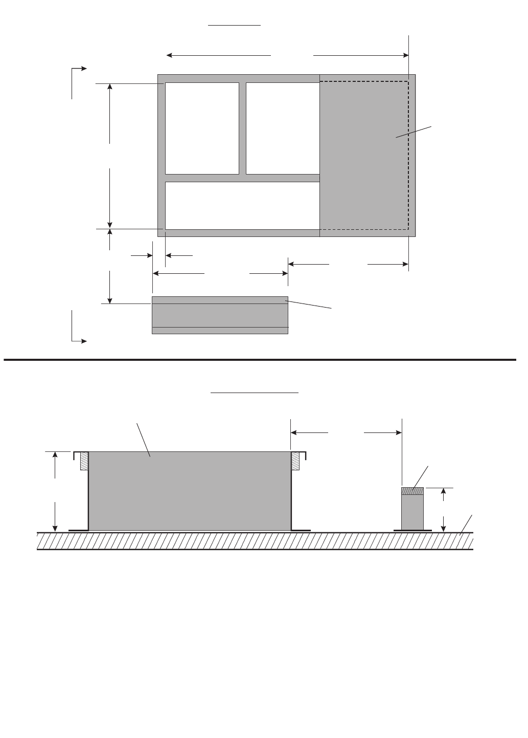
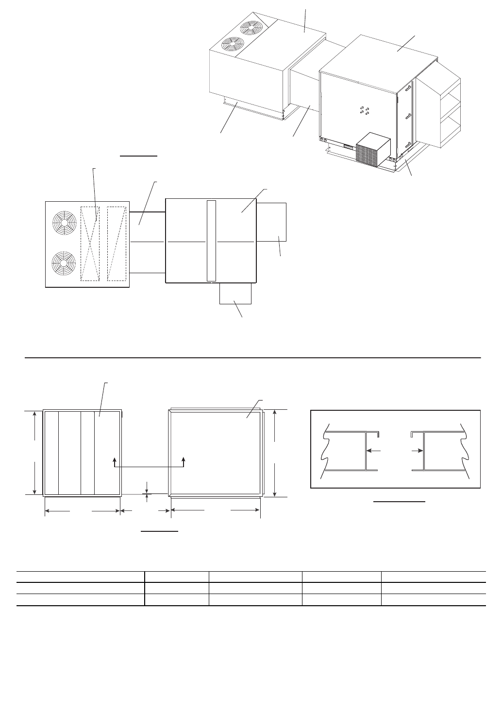
Fig. 7 — 62MB,MC040 Indoor Unit Dimensions
3.95
11.09
8.43
13.26
16.02
2.67
12.45
3.48
7.69
29.88
27.19
25.12
29.75
31.24
29.75 EXHAUST
AIR
OUTSIDE
AIR
OPTIONAL
(INDOOR) PREHEATER
LEFT SIDE FRONT SIDE
POWER
ENTRY
10.75 12.75
12.45
19.75
2.33
.75
3.52
7.53
29.98
SUPPLY
AIR
RETURN
AIR* HORIZONTAL
UNITS ONLY*
REAR SIDE
45.75
SUPPLY AIR
(OPTIONAL)
4.83
7.13
3.91
11.15
10.50
3.95
5.34
TOP SIDE
RETURN AIR
(OPTIONAL)
16.00
OPTIONAL
INDOOR PREHEATER
ERV
WHEEL
19.25
22.90
10
27.19
25.12
RIGHT SIDE
13.25
16
AA
VIEW A-A
REQUIRED SERVICE
CLEARANCES
*30 in. service clearance required
on either Left or Right side for
ERV wheel removal.
NOTE: All dimensions are in
inches.
Front 16 in.
Rear 0in.
Left* 18 in.
Right* 18 in.
7
OUTSIDE AIR HOOD
12.29
5.35
EXHAUST AIR HOOD 3.55
TOP OF CURB
13.72
RIGHT SIDE
OUTSIDE AIR HOOD
EXHAUST AIR HOOD
5.31
13.5
16.00
LEFT SIDE
10.75 12.75
12.45
19.75
2.33
.75
3.52
7.53
29.98
SUPPLY
AIR
RETURN
AIR* HORIZONTAL
UNITS ONLY*
3.95
11.09
8.43
13.26
16.02
2.67
12.45
3.48
7.69
29.88
EXHAUST
AIR
OUTSIDE
AIR
POWER
ENTRY
45.75
13.38
11.00
8.97
12.96
SUPPLY AIR
(OPTIONAL)
4.83
7.13
3.91
11.15
10.50
3.95
5.34
OUTSIDE AIR HOOD AND
OPTIONAL PREHEATER
RETURN AIR
(OPTIONAL)
AA
VIEW A-A
ERV
WHEEL
16.00
10
REAR SIDE FRONT SIDE
TOP SIDE
29.75
29.75
EXHAUST AIR HOOD
Fig. 8 — 62MD,ME040 Outdoor Unit Dimensions
REQUIRED SERVICE
CLEARANCES
*30 in. service clearance required
on either Left or Right side for
ERV wheel removal.
NOTE: All dimensions are in
inches.
Front 27.5 in.
Rear 10 in.
Left* 20 in.
Right* 20 in.
8
11.00
18.63
14.50
18.63
5.58
5.58
5.53
3.34
SUPPLY RETURN
REAR SIDE
6.13
12.90
21.10
RIGHT SIDE
10.50
11.00
10.66
2.10
21.10
3.63
15.40
EXHAUST AIR
LEFT SIDE
15.25
23.00
8.63
3.88
OUTSIDE AIR
FRONT SIDE
6.97
POWER ENTRY / OPTIONAL
DISCONNECT LOCATION
10.32
(OPTIONAL)
AIRFLOW TEST
PORTS
OPTIONAL
PREHEATER
(INDOOR)
ACCESS DOOR
18.88
VIEW A-A
OPTIONAL RETURN AIR
(BOTTOM RETURN ONLY)
SUPPLY AIR
(BOTTOM SUPPLY ONLY)
OPTIONAL PREHEATER
10.93
6.18
12.98
3.46
9.25
6.65
6.60
10.39 19.04
AA
TOP SIDE
EXHAUST AIR OUTLET
37.14
42.6 39.03
PREHEATER CABINET
Fig. 9 — 62MB,MC075,120 Indoor Unit Dimensions
REQUIRED SERVICE
CLEARANCES
*39 in. service clearance required
for ERV wheel removal.
Front 31 in.
Rear 0in.
Left 24 in.
Right* 39 in.
NOTE: All dimensions are in inches.
9
Fig. 10 — 62MD,ME075,120 Outdoor Unit Dimensions
39.8
37.14
43.10
18.74
6.39
35.711
39.03
9.60
9.19
10.25
11.06
6.43
14.45
18.55
5.62
3.10
2.86
10.32
6.97
SUPPLY RETURN
REAR SIDE
POWER ENTRY/
OPTIONAL DISCONNECT
*NOTE*
DISCONNECT
LOCATION IS APPROXIMATE
FRONT SIDE
13.24
9.59
42.60
A
4.11
AIRFLOW
TEST PORTS
(OPTIONAL)
TOP OF CURB
ACCESS DOOR
DETAIL A
SEE DETAIL
A
LEFT SIDE
ACCESS DOOR
RIGHT SIDE
OPTIONAL RETURN AIR
(BOTTOM RETURN ONLY)
SUPPLY AIR
(BOTTOM SUPPLY ONLY)
OPTIONAL PREHEATER
OUTDOOR AIR HOOD
10.93
6.18
12.98
3.46
9.25
6.65
6.60
10.39
18.69
.87
19.04
ERV WHEEL
AA
TOP SIDE
9.60
2.87
10.35
EXHAUST AIR HOOD
VIEW A-A
REQUIRED SERVICE
CLEARANCES
*39 in. service clearance required
for ERV wheel removal.
Front 31 in.
Rear 0in.
Left 24 in.
Right* 39 in.
NOTE: All dimensions are in inches.
10
15.50
20.00
9.62
6.92
6.48
23.00
25.00
8.20
3.16
REAR SIDE
26.60
10.76
26.60
21.84
49.55
RIGHT SIDE
36.00
22.00
11.18
26.60
57.91
FRONT SIDE
14.57
12.50
43.38
14.86
62.03
LEFT SIDE
SUPPLY
AIR
AIRFLOW TEST
PORTS (OPTIONAL)
ACCESS DOOR
OUTSIDE AIR
EXHAUST AIR
ACCESS DOOR
POWER ENTRY
(OPTIONAL DISCONNECT)
EXHAUST AIR OUTLET
RETURN AIR OPENING
SUPPLY AIR OPENING
TOP SIDE
8.21
15.28
6.10
22.33
15.63
8.20
8.68
13.75
RETURN
AIR
AA
ERV WHEEL
VIEW A-A
OPTIONAL PREHEATER
PREHEATER CABINET
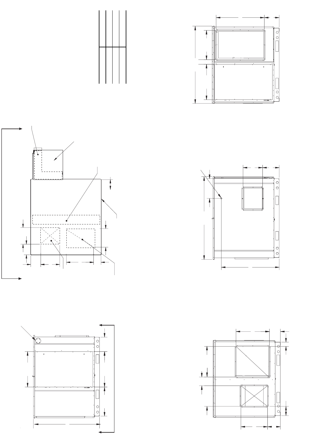
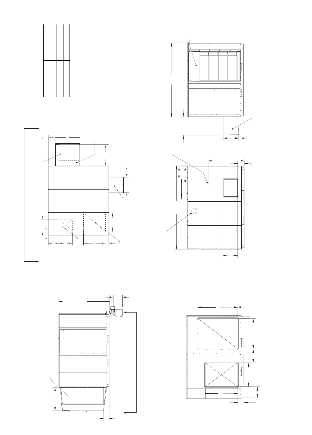
Fig. 11 — 62MB,MC170-285 Indoor Unit Dimensions
REQUIRED SERVICE
CLEARANCES
*55 in. service clearance required for
ERV wheel removal.
Front 39 in.
Rear 0in.
Left 32 in.
Right* 55 in.
NOTE: All dimensions are in inches.

11
20.78
9.16
OUTSIDE AIR HOOD
RIGHT SIDE
6.94
EXHAUST AIR HOOD
FRONT SIDE
A
4.61
TOP OF CURB
15.50
20.00
9.62
6.92
6.48
23.00
25.00
8.20
3.16
REAR SIDE
SUPPLY
AIR
RETURN
AIR
EXHAUST AIR HOOD
RETURN AIR OPENING
SUPPLY AIR OPENING
OUTSIDE AIR HOOD
TOP SIDE
8.21
16.19
15.28
6.10
22.33
15.63
8.20
8.68
13.75
26.45
.64
OPTIONAL PREHEATER
AA
ERV WHEEL
14.57
12.50
43.38
14.86
62.03
LEFT SIDE
EXHAUST AIR
POWER ENTRY
(OPTIONAL DISCONNECT) 14.84
15.96
OUTSIDE AIR HOOD
VIEW A-A
49.55
57.91
Fig. 12 — 62MD,ME170-285 Outdoor Unit Dimensions
REQUIRED SERVICE
CLEARANCES
*55 in. service clearance required for
ERV wheel removal.
Front 39 in.
Rear 0in.
Left 32 in.
Right* 55 in.
NOTE: All dimensions are in inches.
12
29.00
2.78
9.03
54.00
27.00
5.11
67.39
FRONT SIDE
20.00
17.00
49.1
72.63
LEFT SIDE
OUTSIDE
AIR
ACCESS
DOOR
POWER ENTRY
(OPTIONAL DISCONNECT)
EXHAUST
AIR
OPTIONAL AIRFLOW
TEST PORTS
29.00 14.63
65.21
RIGHT SIDE
ACCESS DOOR
37.50
19.00
2.87
28.50
37.50
6.11
7.66
6.11 6.61
REAR SIDE
SUPPLY
AIR
RETURN
AIR
TOP SIDE
EXHAUST AIR OUTLET
21.11
RETURN AIR OPENING
(BOTTOM RETURN ONLY)
6.93
25.76
18.62
8.01
15.94
6.88
SUPPLY AIR OPENING
(BOTTOM SUPPLY ONLY)
AA
VIEW A-A
OPTIONAL PREHEATER
PREHEATER CABINET
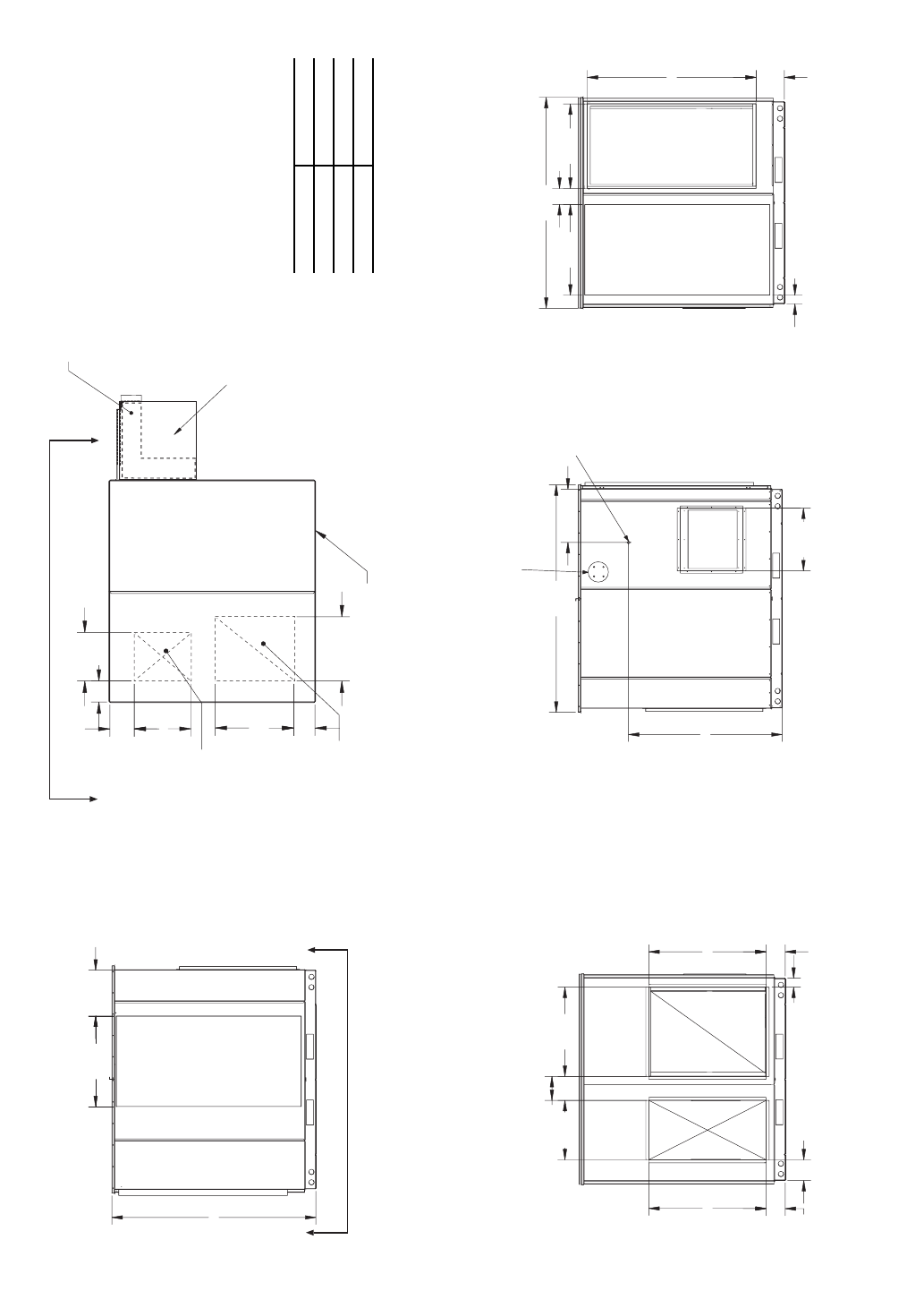
Fig. 13 — 62MB,MC330-640 Indoor Unit Dimensions
REQUIRED SERVICE
CLEARANCES
*62 in. service clearance required
for ERV wheel removal.
Front 50 in.
Rear 0in.
Left 40 in.
Right* 62 in.
NOTE: All dimensions are in inches.
13
26.41
8.68
OUTSIDE AIR HOOD
RIGHT SIDE
18.81
17.96
9.22
EXHAUST AIR HOOD
FRONT SIDE
A
4.21
TOP SIDE
OUTSIDE AIR HOOD
OPTIONAL PREHEATER
29.44
7.63
19.69
EXHAUST AIR HOOD
21.11
RETURN AIR OPENING
(BOTTOM RETURN ONLY)
6.93
25.76
18.62
8.01
15.94
6.88
SUPPLY AIR OPENING
(BOTTOM SUPPLY ONLY)
A A
20.00
17.00
49.1
72.63
LEFT SIDE
POWER ENTRY
(OPTIONAL DISCONNECT)
EXHAUST
AIR
OPTIONAL AIRFLOW
TEST PORTS
VIEW A-A
TOP OF
CURB
OUTSIDE AIR HOOD
12.52
37.50
19.00
2.87
28.50
37.50
6.11
7.66
6.11 6.61
REAR SIDE
SUPPLY
AIR
RETURN
AIR
65.21
67.39
Fig. 14 — 62MD,ME330-640 Outdoor Unit Dimensions
REQUIRED SERVICE
CLEARANCES
*62 in. service clearance required
for ERV wheel removal.
Front 50 in.
Rear 0in.
Left 40 in.
Right* 62 in.
NOTE: All dimensions are in inches.
14
34.10
2.37
35.08
64.25
9.52
11.31
12.77
98.37
FRONT SIDE
23.25
20.25
9.01
48.98
107.75
LEFT SIDE
34.10
21.86
77.41
RIGHT SIDE
49.01
35.75
28.00
16.19
7.69
7.69 13.11
REAR SIDE
RETURN AIR
SUPPLY
AIR
POWER ENTRY/
OPTIONAL DISCONNECT
LOCATION
AIRFLOW TEST
PORTS (OPTIONAL)
ACCESS DOOR
ACCESS DOOR
EXHAUST AIR OUTLET
RETURN AIR OPENING
SUPPLY AIR OPENING
31.67
6.43
34.73
21.88
17.07
6.42 18.75
TOP SIDE
11.02
VIEW A-A
AA
OUTSIDE AIR
EXHAUST AIR
40.12
34 7/8
40
OPTIONAL PREHEATER
PREHEATER CABINET
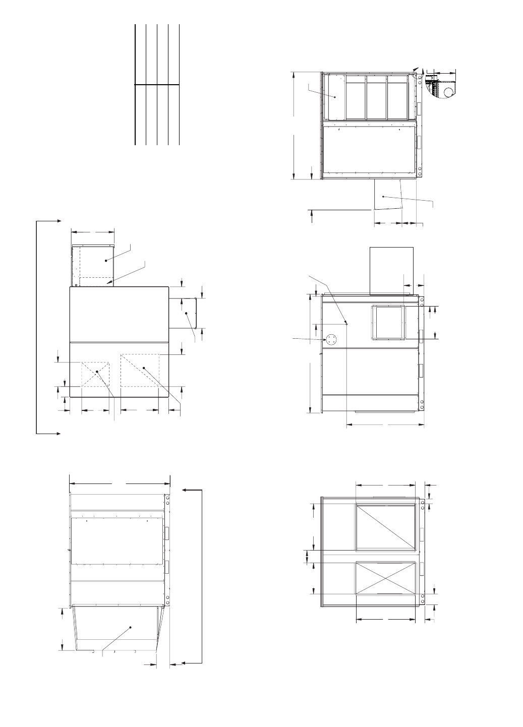
Fig. 15 — 62MB,MC750,950 Indoor Unit Dimensions
REQUIRED SERVICE
CLEARANCES
*72 in. service clearance required
for ERV wheel removal.
Front 65 in.
Rear 0in.
Left 50 in.
Right* 72 in.
NOTE: All dimensions are in inches.
15
33.71
8.83
OUTSIDE AIR HOOD
B
21.58
2.89
23.81
EXHUAST AIR HOOD
4.40
17.16
23.22
EXHAUST AIR HOOD
RETURN AIR OPENING
SUPPLY AIR OPENING
31.67
6.43
34.73
21.88
17.07
6.42
18.75
OUTSIDE AIR HOOD
TOP SIDE
OPTIONAL PREHEATER
40.12
11.02
A A
34 7/8
23.25
20.25
9.01
48.98
107.75
LEFT SIDE
POWER ENTRY/
OPTIONAL DISCONNECT
LOCATION
AIRFLOW TEST
PORTS (OPTIONAL)
EXHAUST AIR
OUTSIDE AIR HOOD
RIGHT SIDE
FRONT SIDE
49.01
35.75
28.00
16.19
7.69
7.69 13.11
REAR SIDE
RETURN AIR
SUPPLY
AIR
VIEW A-A
77.41
98.37
40
Fig. 16 — 62MD,ME750,950 Outdoor Unit Dimensions
REQUIRED SERVICE
CLEARANCES
*72 in. service clearance required
for ERV wheel removal.
Front 65 in.
Rear 0in.
Left 50 in.
Right* 72 in.
NOTE: All dimensions are in inches.
16
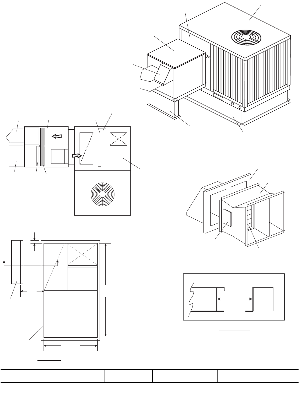
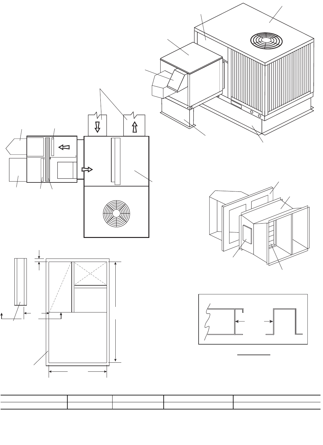
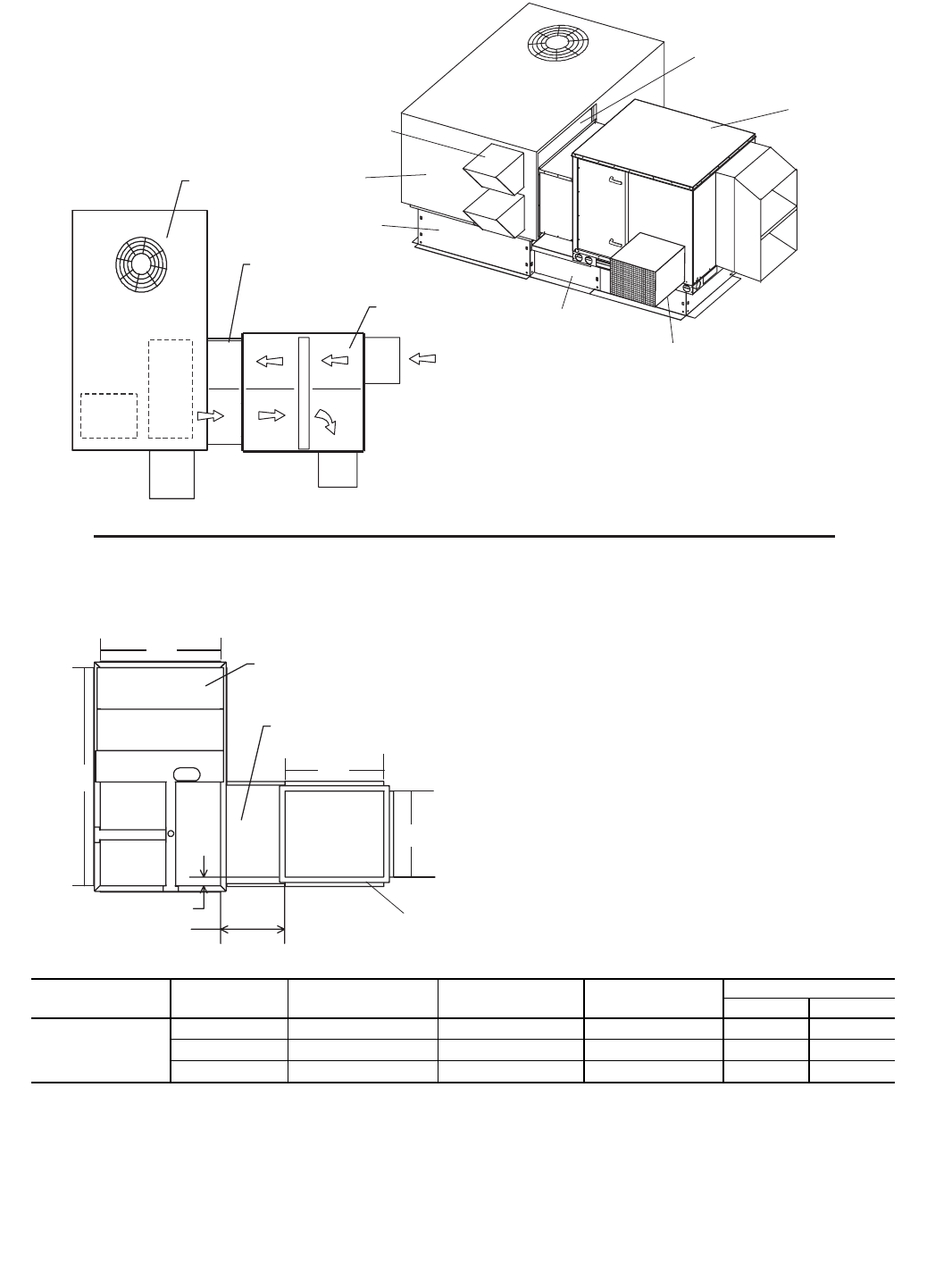
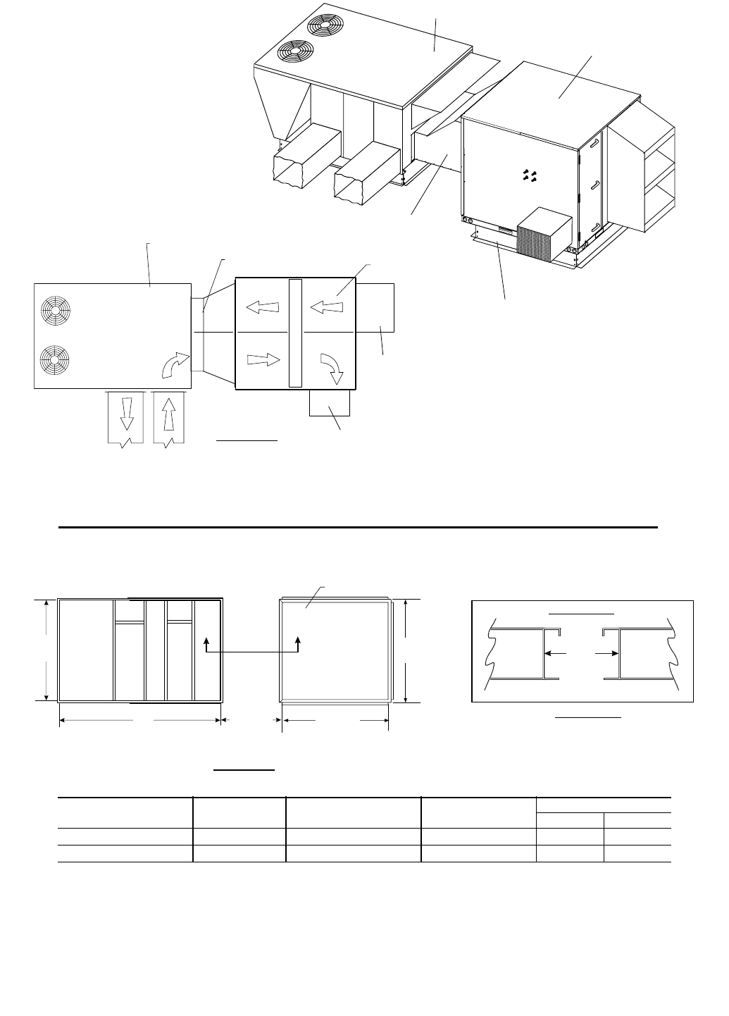
Outside air hood
with aluminum
water entrain-
ment filter.
Includes baro-
metric intake
damper.
Rooftop Unit
Filter access door
shipped with Rooftop
Unit
62M040 Unit
Accessory ERV
Equipment support Standard Rooftop
Unit roof curb
3 to 6 Ton Rooftop Unit
Evaporation
Coil
Filters
Filter
ERV
wheel
Filter
Exhaust
hood
Outside
air hood
Supply
Blower
EXH
Rooftop Curb
Accessory ERV
Equipment support
35"
Side View A-A
AA
Rooftop
Unit
Curb
ERV
Unit
Support
67 3/8”
37”
3”
35”
Supply
Return
Accessory Transition
Panel covering
return chamber
Access door to
adjust balancing
damper
To 62M040 Unit
Balancing damper
Top View
ROOFTOP UNIT MODEL ROOFTOP SIZE TRANSITION P/N ROOFTOP ECONOMIZER ERV EQUIPMENT SUPPORT P/N
48/50HJ,TJ,TM 004-007 62M-AATR-HJ36-D 62MA-900---004 62MA-900---001
TRANSITION DETAIL
ROOF CURB LOCATION DETAIL
Fig. 17 — 62MD,ME040 Coupled with Carrier 48/50HJ,TJ,TM004-007 Vertical Discharge Rooftop Unit
LEGEND
ERV — Energy Recovery Ventilator
17
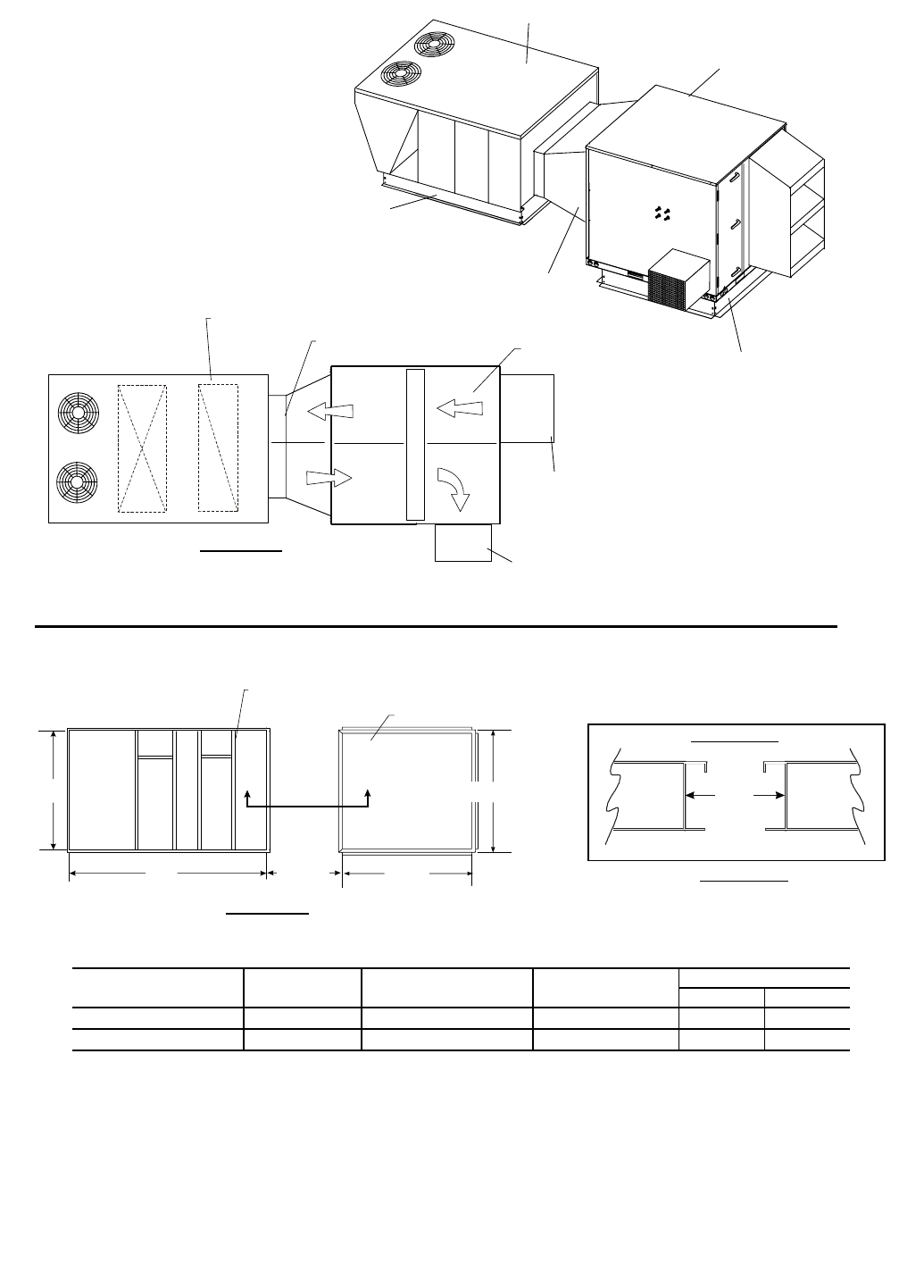
Accessory ERV
Equipment support
Outside air hood
with aluminum
water entrain-
ment filter.
Includes baro-
metric intake
damper.
Rooftop Unit
Filter access door
shipped with Rooftop
Unit
62M040 Unit
Standard Rooftop
Unit roof curb
3 to 6 Ton Rooftop Unit
Filter
ERV
wheel
Filter
Exhaust
hood
Outside
air hood
Supply
Blower
EXH
Rooftop Curb
Accessory ERV
Equipment support
AA
67 3/8”
37”
3”
35”
Supply
Return
To 62M040 Unit
Access door to
adjust balancing
damper
Accessory Transition
Panel covering
return chamber
Balancing damper
35"
Side View A-A
Rooftop
Unit
Curb
ERV
Unit
Support
Field-Supplied
Duct
ROOFTOP UNIT MODEL ROOFTOP SIZE TRANSITION P/N ROOFTOP ECONOMIZER ERV EQUIPMENT SUPPORT P/N
48/50HJ,TJ,TM 004-007 62M-AATR-HJ36-D 62MA-900---008 62MA-900---001
TRANSITION DETAIL
ROOF CURB LOCATION DETAIL
Fig. 18 — 62MD,ME040 Coupled with Carrier 48/50HJ,TJ,TM004-007 Horizontal Discharge Rooftop Unit
LEGEND
ERV — Energy Recovery Ventilator
18
Rooftop Unit
62M040 Unit
Accessory ERV
Equipment support
Accessory Transition
(Includes front panel)
Filter
ERV
wheel
Filter
Exhaust
hood
Outside air hood
Supply
Rooftop Curb
Accessory ERV
Equipment support
AA
Supply
2 Piece front
panel covers
return chamber
Access door to
adjust balancing
damper
Accessory Transition
Return
Rooftop Unit
80 5/16”35”
44 11/16”
Return
Top Vi ew
To 62M040 Unit
35"
Side View A-A
Rooftop
Unit
Curb
ERV
Unit
Support
4 3/8”
ROOFTOP UNIT MODEL ROOFTOP SIZE TRANSITION P/N ERV EQUIPMENT SUPPORT P/N
48/50PG 03-07 62M-AATR-HJ36-D 62MA-900---001
TRANSITION DETAIL
ROOF CURB LOCATION DETAIL
Fig. 19 — 62MD,ME040 Coupled with Carrier 48/50PG03-07 Vertical Discharge Rooftop Unit
LEGEND
ERV — Energy Recovery Ventilator
19
Rooftop Unit
62M040 Unit
Accessory ERV
Equipment support
Accessory Transition
(Includes front panel)
Filter
ERV
wheel
Filter
Exhaust
hood
Outside air hood
Rooftop Curb
Accessory ERV
Equipment support
AA
2 Piece front
panel covers
return chamber
Access door to
adjust balancing
damper
To 62M040 Unit
Accessory Transition
Rooftop Unit
80 5/16”35”
44 11/16”
Top View
35"
Side View A-A
Rooftop
Unit
Curb
ERV
Unit
Support
4 3/8”
ROOFTOP UNIT MODEL ROOFTOP SIZE TRANSITION P/N ERV EQUIPMENT SUPPORT P/N
48/50PG 03-07 62M-AATR-HJ36-D 62MA-900---001
TRANSITION DETAIL
ROOF CURB LOCATION DETAIL
LEGEND
ERV — Energy Recovery Ventilator
Fig. 20 — 62MD,ME040 Coupled with Carrier 48/50PG03-07 Horizontal Discharge Rooftop Unit
20
67 3/8"
37 3/16"
36"
3"
35 "34 3/8"
Return
Air
Standard roof curb fo
r
3 to 6 ton rooftop unit
62MA-900---001
Equipment Support
10.4"
Equipment Support
Roof
14"
Standard Roof curb
for 3 to 6 ton roof top unit
"A-A" SIDE VIEW
TOP VIEW
A
A
62MA-900---001
Supply
Air
35 "
ROOF CURB LAYOUT
Fig. 21 — 62MD,ME040 Coupled with Carrier 48/50HJ,TJ,TM004-007 Rooftop Unit
21
2 3/4"
20"
Unit curb
ERV curb
Rooftop unit
Rooftop unit
Accessory Transition
62M075,120 ERV Unit
Rooftop
Unit curb
Locator Pieces ( included with ERV Curb)
Cover panel provided
ERV curb
27”
30.5”
B
Rainhoods for
optional economizer
RETURN
SUPPLY
ERV Wheel
A
Filter door shipped
with Rooftop unit.
62M ERV Unit
Locator
pieces
(included with
ERV curb,
must be watertight)
ROOFTOP UNIT
MODEL ROOFTOP SIZE TRANSITION P/N ERV CURB P/N ROOFTOP
ECONOMIZER
DIMENSIONS (in.)
AB
48/50HJ,TF,TJ,TM
004-007 62M-ATR-HJ36-D 62M-A-CRB-14MC 62MA-900---004 673/8373/16
008,009 62M-ATR-HJ78-D 62M-A-CRB-14MC 62MA-900---005 781/450
012,014 62M-ATR-HJ1012-D 62M-A-CRB-14MC 62MA-900---006 781/450
LEGEND
NOTE: When using a 62M ERV unit coupled with a Carrier
rooftop unit, the rooftop factory or field-installed economizer
cannot be used. Use the 62M economizer instead.
ERV — Energy Recovery Ventilator
ROOF CURB LOCATION DETAIL
Fig. 22 — 62MD,ME075,120 Coupled with Carrier 48/50HJ,TF,TJ,TM004-014 Vertical Discharge Rooftop Unit
22
2 3/4"
20"
Locator
pieces
ERV curb
Rooftop unit
Accessory Transition
62M075,120
ERV Unit
ERV curb
27"
30.5"
B
Horizontal supply and
return duct (field supplied)
ERV Wheel
A
Optional Horizontal
Economizer
(included with
ERV curb,
must be watertight)
Filter door shipped
with Rooftop unit.
62M ERV Unit
Rooftop Unit
Rooftop
Unit curb
Locator Pieces ( included with ERV curb)
Cover panel provided
ROOFTOP UNIT
MODEL ROOFTOP SIZE TRANSITION P/N ERV CURB P/N ROOFTOP
ECONOMIZER
DIMENSIONS (in.)
AB
48/50HJ,TF,TJ,TM
004-007 62M-ATR-HJ36-H62M-A-CRB-14MC 62MA-900---008 673/8373/16
008,009 62M-ATR-HJ78-H62M-A-CRB-14MC 62MA-900---009 781/450
012,014 62M-ATR-HJ1012-H62M-A-CRB-14MC 62MA-900---010 781/450
LEGEND
NOTE: When using a 62M ERV unit coupled with a Carrier
rooftop unit, the rooftop factory or field-installed economizer
cannot be used. Use the 62M economizer instead.
ERV — Energy Recovery Ventilator
ROOF CURB LOCATION DETAIL
Fig. 23 — 62MD,ME075,120 Coupled with Carrier 48/50HJ,TF,TJ,TM004-014 Horizontal Discharge Rooftop Unit
23
Supply
Return
ERV Wheel
62M075,120 ERV Unit
TOP VIEW
A
B
Supply Return
30 1/12"
27"
2 3/4"
20"
Rooftop Unit
Accessory Transition
(Includes front panel)
62M ERV Unit
ERV Curb
Locator pieces
(included with
ERV Curb)
Rooftop Unit
Accessory
Transition
ERV Curb
Side View A-A
20"
Rooftop
Unit
Curb
ERV
Unit
Curb
Curb Detail
Rooftop Unit Curb
AA
Locator
pieces
(included with
ERV curb,
must be watertight)
ROOFTOP MODEL ROOFTOP SIZE 62M TRANSITION ERV CURB DIMENSIONS (in.)
AB
48/50PG 03-07 62M-ATR-PG26-D 62M-A-CRB-14MC 805/16 4411/16
08-14 62M-ATR-PG712-D 62M-A-CRB-14MC 923/45315/16
LEGEND
NOTE: When using a 62M ERV unit coupled with a Carrier
rooftop unit, the rooftop factory or field-installed econo-
mizer cannot be used.
ERV — Energy Recovery Ventilator
ROOF CURB LOCATION DETAIL
Fig. 24 — 62MD,ME075,120 Coupled with Carrier 48/50PG03-14 Vertical Discharge Rooftop Unit
24
ERV Wheel
TOP VIEW
A
B
30 1/12"
27"
2 3/4"
20"
Accessory Transition
(Includes front panel)
62M Unit
Rooftop Unit
ERV Curb
Rooftop Unit
62M075-120 ERV Unit
ERV Curb
Locator pieces
(included with
ERV Curb)
Rooftop Unit Curb
Accessory
Transition
Side View A-A
20"
Rooftop
Unit
Curb
ERV
Unit
Curb
AA
Curb Detail
Locator
pieces
(included with
ERV curb,
must be watertight)
ROOFTOP MODEL ROOFTOP SIZE 62M TRANSITION ERV CURB DIMENSIONS (in.)
AB
48/50PG 03-07 62M-ATR-PG26-H62M-A-CRB-14MC 805/16 4411/16
08-14 62M-ATR-PG712-H62M-A-CRB-14MC 923/45315/16
LEGEND
NOTE: When using a 62M ERV unit coupled with
a Carrier rooftop unit, the rooftop factory or field-
installed economizer cannot be used.
ERV — Energy Recovery Ventilator
ROOF CURB LOCATION DETAIL
Fig. 25 — 62MD,ME075,120 Coupled with Carrier 48/50PG03-14 Horizontal Discharge Rooftop Unit
25
Top View
To
p
View
Locator Pieces
(included with ERV curb,
must be watertight) ERV Curb
Filter door shipped with
Rooftop unit
Rooftop curb
Rainhoods for
optional economizer
ERV Wheel
SUPPLY
RETURN
30”
49 5/8"
B
A
38"
2 3/4"
45 1/2"
62M ERV Unit
62M170-285 ERV Unit
Accessory Transition
Rooftop
Unit
Rooftop unit
Locator Pieces ( included with ERV curb)
Cover panel provided
Rooftop
Unit curb
ERV curb
ROOFTOP UNIT
MODEL ROOFTOP SIZE TRANSITION P/N ERV CURB P/N ROOFTOP
ECONOMIZER
DIMENSIONS (in.)
AB
48/50HJ,TF,TJ,TM
004-007 62M-BTR-HJ36-D 62M-B-CRB-14MC 62MA-900---004 673/8373/16
008,009 62M-BTR-HJ78-D 62M-B-CRB-14MC 62MA-900---005 781/450
012,014 62M-BTR-HJ1012-D 62M-B-CRB-14MC 62MA-900---006 781/450
LEGEND
NOTE: When using a 62M ERV unit coupled with a Carrier
rooftop unit, the rooftop factory or field-installed economizer
cannot be used. Use the 62M economizer instead.
ERV — Energy Recovery Ventilator
ROOF CURB LOCATION DETAIL
Fig. 26 — 62MD,ME170-285 Coupled with Carrier 48/50HJ,TF,TJ,TM004-014 Vertical Discharge Rooftop Unit
26
Top View
Top View
Rooftop Unit
Horizontal
Return duct
(field supplied)
Optional
Horizontal
Economizer
ERV Wheel
30"
49 5/8"
B
A
38"
2 3/4"
45 1/2"
Rooftop
Unit curb
Locator Pieces ( included with ERV Curb)
Cover Panel provided
ERV curb
Rooftop
Unit
Filter door shipped
with Rooftop unit.
62M ERV Unit
ERV Curb
62M170-285 ERV Unit
Accessory Transition
Locator
pieces
(included with
ERV curb,
must be watertight)
ROOFTOP UNIT
MODEL ROOFTOP SIZE TRANSITION P/N ERV CURB P/N ROOFTOP
ECONOMIZER
DIMENSIONS (in.)
AB
48/50HJ,TF,TJ,TM
004-007 62M-BTR-HJ36-H62M-B-CRB-14MC 62MA-900---008 673/8373/16
008,009 62M-BTR-HJ78-H62M-B-CRB-14MC 62MA-900---009 781/450
012,014 62M-BTR-HJ1012-H62M-B-CRB-14MC 62MA-900---010 781/450
LEGEND
NOTE: When using a 62M ERV unit coupled with a Carrier
rooftop unit, the rooftop factory or field-installed economizer
cannot be used. Use the 62M economizer instead.
ERV — Energy Recovery Ventilator
ROOF CURB LOCATION DETAIL
Fig. 27 — 62MD,ME170-285 Coupled with Carrier 48/50HJ,TF,TJ,TM004-014 Horizontal Discharge Rooftop Unit
27
ERV
Unit
Curb
67 1/16"*
74 1/4"
62M ERV unit
ERV curb
Unit curb
Rooftop Unit
ERV Wheel
Rooftop Unit Curb
ERV Curb
15 to 25 Ton Rooftop Unit
Transition
*Optional
Economizer
SIDE VIEWTOP VIEW
18 11/16" 49 5/8"
45 1/2"
44 3/4"
SUPPLY
RETURN
Rooftop Unit
Accessory Transition
Accessory
Transition
62M170-285
ERV Unit 62M170-285
ERV Unit
TOP VIEW
44 3/4"
Rooftop
Unit
Curb
SIDE VIEW A-A
AA
ROOFTOP UNIT
MODEL ROOFTOP SIZE TRANSITION P/N ERV CURB P/N
48/50TJ,TM 016-028 62M-BTR-HJ1525-D 62M-B-CRB-14S
48/50HJ 015,017 62M-BTR-HJ1525-D 62M-B-CRB-14S
LEGEND
NOTES:
1. The 62M ERV unit cannot be coupled with
horizontal return 48/50TJ,TM016-028 and
48/50HJ015,017 units.
2. The ERV unit can be used with a factory-
installed economizer, if desired.
ERV — Energy Recovery Ventilator
*Length is 891/16
″for 48/50TM028 units.
ROOF CURB LOCATION DETAIL
Fig. 28 — 62MD,ME170-285 Coupled with Carrier 48/50TJ,TM016-028
and 48/50HJ015,017 Vertical Discharge Rooftop Unit
28
Supply
ERV Wheel
TOP VIEW
A
B
Supply Return
49 5/8"
45 1/2"
0"
38 3/4"
Accessory Transition
(Includes front panel)
62M ERV Unit
ERV Curb
Rooftop Unit
ERV Curb
Accessory
Transition
62M170-285 ERV Unit
Rooftop Unit
Locator pieces
(included with
ERV Curb)
Side View A-A
38 3/4"
Rooftop
Unit
Curb
ERV
Unit
Curb
AA
Curb Detail
Rooftop Unit Curb
Return
Locator
pieces
(included with
ERV curb,
must be watertight)
ROOFTOP MODEL ROOFTOP SIZE 62M TRANSITION ERV CURB DIMENSIONS (in.)
AB
48/50PG 03-07 62M-BTR-PG26-D 62M-A-CRB-14MC 805/16 4411/16
08-14 62M-BTR-PG712-D 62M-A-CRB-14MC 923/45315/16
LEGEND
NOTE: When using a 62M ERV unit coupled with a Carrier roof-
top unit, the rooftop factory or field-installed economizer cannot
be used.
ERV — Energy Recovery Ventilator
ROOF CURB LOCATION DETAIL
Fig. 29 — 62MD,ME170-285 Coupled with Carrier 48/50PG03-14 Vertical Discharge Rooftop Unit
29
ERV Wheel
62M170-285 ERV Unit
TOP VIEW
A
B
49 5/8"
45 1/2"
0"
38 3/4"
Accessory Transition
(Includes front panel)
62M ERV Unit
Rooftop Unit
ERV Curb
Accessory Transition
Rooftop Unit
ERV Curb
Locator pieces
(included with
ERV Curb)
Side View A-A
38 3/4"
Rooftop
Unit
Curb
ERV
Unit
Curb
AA
Curb Detail
Rooftop Unit Curb
Locator
pieces
(included with
ERV curb,
must be watertight)
ROOFTOP MODEL ROOFTOP SIZE 62M TRANSITION ERV CURB DIMENSIONS (in.)
AB
48/50PG 03-07 62M-BTR-PG26-H62M-B-CRB-14MC 805/16 4411/16
08-14 62M-BTR-PG712-H62M-B-CRB-14MC 923/45315/16
LEGEND
NOTE: When using a 62M ERV unit coupled with a Carrier
rooftop unit, the rooftop factory or field-installed economizer
cannot be used.
ERV — Energy Recovery Ventilator
ROOF CURB LOCATION DETAIL
Fig. 30 — 62MD,ME170-285 Coupled with Carrier 48/50PG03-14 Horizontal Discharge Rooftop Unit
30
Side View A-A
44 3/4"
Rooftop
Unit
Curb
ERV
Unit
Curb
AA
Curb Detail
Rooftop Unit
62M ERV Unit
Rooftop Unit
Relief Hood
Top View
62M170-285 ERV Unit
O/A Hood
Accessory
Transition
leeh
W
V
RE
(field supplied)
Horizontal / Return Duct
Outside Air Hood (See Note 2)
A
Rooftop Unit Curb
B
Top View
49 5/8”
45 1/2”
Rooftop Unit
Curb
ERV Curb
44 3/4”ERV Curb
Accessory
Transition
ROOFTOP MODEL ROOFTOP SIZE 62M TRANSITION ERV CURB DIMENSIONS (in.)
AB
48/50PG 20-28 62M-BTR-HG1525-H62M-B-CRB-14MC 114.4 78.6
48/50HJ 020-028 62M-BTR-HG1525-H62M-B-CRB-14MC 114.4 78.6
LEGEND
NOTES:
1. The ERV unit can be used with a factory-
installed economizer, if desired.
2. Transition includes a new outside air hood,
which allows air intake through the front of the
hood rather than the bottom. The new hood will
use the filters from the original rooftop unit
hood.
ERV — Energy Recovery Ventilator
O/A — Outdoor Air
ROOF CURB LOCATION DETAIL
Fig. 31 — 62MD,ME170-285 Coupled with Carrier 48/50PG20-28
and 48/50HJ020-028 Horizontal Discharge Rooftop Unit
31
Side View A-A
44 3/4"
Rooftop
Unit
Curb
ERV
Unit
Curb
AA
Curb Detail
Rooftop Unit
Rooftop Unit
Relief Hood
Top View
A
Rooftop Unit Curb
B
ERV Curb
62M170-285 ERV Unit
O/A Hood
Top View
Accessory
Transition
le
ehW VRE
62M ERV Unit
Outside Air Hood (See
Note 2)
49 5/8”
YLP
P
U
S
NRUT
E
R
YLPPUS
NRUTER
Standard HVAC Unit
Roofcurb
ERV Curb
44 3/4”
45 1/2”
Accessory
Transition
ROOFTOP MODEL ROOFTOP SIZE 62M TRANSITION ERV CURB DIMENSIONS (in.)
AB
48/50PG 20-28 62M-BTR-HG1525-D 62M-B-CRB-14MC 114.4 78.6
48/50HJ 020-028 62M-BTR-HG1525-D 62M-B-CRB-14MC 114.4 78.6
LEGEND
NOTES:
1. The ERV unit can be used with a factory-
installed economizer, if desired.
2. Transition includes a new outside air hood,
which allows air intake through the front of
the hood rather than the bottom. The new
hood will use the filters from the original
rooftop unit hood.
ERV — Energy Recovery Ventilator
O/A — Outdoor Air
ROOF CURB LOCATION DETAIL
Fig. 32 — 62MD,ME170-285 Coupled with Carrier 48/50PG20-28
and 48/50HJ020-028 Vertical Discharge Rooftop Unit

32
O/A hood
Top View
62M ERV Unit
Filter access door
shipped with
transition
55 13/32"
Accessory
Transition
Accessory
Transition
Rooftop Unit
62M330-640 ERV Unit
Rooftop Unit
Exhaust hood
Outside air hood
for optional
economizer
Rooftop Unit curb
ERV curb
60 11/32"
9"
50"
78 1/4"
33 1/2"
33 1/2"
To
p
View
Outside air hood
for optional
economizer
ERV Wheel
Side View A-A
Return
Supply
Rooftop
Unit
Curb
ERV
Unit
Curb
ERV Curb
Return
Supply
AA
ROOFTOP UNIT MODEL ROOFTOP SIZE TRANSITION P/N ERV CURB P/N ROOFTOP ECONOMIZER
48/50HJ,TF,TJ,TM 012,014 62M-CTR-HJ1012-D 62M-C-CRB-14M 62MA-900---006
ROOF CURB LOCATION DETAIL
LEGEND
NOTE: When using a 62M ERV unit coupled with a
Carrier rooftop unit, the rooftop factory or field-
installed economizer cannot be used. Use the 62M
economizer instead.
ERV — Energy Recovery Ventilator
O/A — Outdoor Air
Fig. 33 — 62MD,ME330-640 Coupled with Carrier 48/50HJ,TF,TJ,TM012,014 Vertical Discharge Rooftop Unit
33
62M ERV Unit
Horizontal
supply duct
Horizontal
return (field
supplied)
Filter access door
shipped with
transition
S/A
R/A
O/A hood
Top View
55 13/32"
Accessory
Transitions 62M330-640
ERV Unit
Rooftop Unit
Exhaust hood
Rooftop Unit
Accessory
Transition
ERV Curb
Accessory
Transitions 62M 330-640 ERV Unit
Exhaust hood
Rooftop Unit curb
ERV Curb
Optional
Horizontal
Economizer
Top View
with Economizer
S/A
Duct
R/A
Duct
60 11/32"
50"
9"
78 1/4"
33 1/2"
Top View
ERV Wheel
(field supplied)
10 to 12 1/2 Ton
Rooftop Unit
AA
33 1/2"
Side View A-A
Rooftop
Unit
Curb
ERV
Unit
Curb
ROOFTOP UNIT MODEL ROOFTOP SIZE TRANSITION P/N ERV CURB P/N ROOFTOP ECONOMIZER
48/50HJ,TF,TJ,TM Without Economizer 012,014 62M-CTR-HJ1012-H62M-C-CRB-14M —
48/50HJ,TF,TJ,TM With Economizer 012,014 62M-CTR-HJ1012-HEC 62M-C-CRB-14M 62MA-900---010
ROOF CURB LOCATION DETAIL
LEGEND
NOTE: When using a 62M ERV unit cou-
pled with a Carrier rooftop unit, the rooftop
factory or field-installed economizer cannot
be used. Use the 62M economizer instead.
ERV — Energy Recovery Ventilator
O/A — Outdoor Air
R/A — Return Air
S/A — Supply Air
Fig. 34 — 62MD,ME330-640 Coupled with Carrier 48/50HJ,TF,TJ,TM012,014 Horizontal Discharge Rooftop Unit
34
55 13/32"
67 1/16"*
53 3/4" 60 11/32"
74 1/4"
Top View
ERV curb
Exhaust hood
Top View
62M330-640
ERV Unit
O/A hood
Economizer
Side View
Side View A-A
ERV Wheel
11 1/2"
53 3/4"
62M ERV Unit
Accessory
Transition
Accessory
Transition
Rooftop Unit Curb
62M ERV Unit
Accessory
Transition
Rooftop Unit
Rooftop Unit
Rooftop Unit Curb
ERV curb
RETURN AIR
SUPPLY AIR
AA
Optional
TJ/HJ 15 to 25 Ton
Rooftop Unit
SUPPLY
RETURN
Rooftop
Unit
Curb
ERV
Unit
Curb
Fig. 35 — 62MD,ME330-640 Coupled with Carrier 48/50TJ,TM016-028 and 48/50HJ015,017
Vertical Discharge Rooftop Unit
ROOFTOP UNIT
MODEL ROOFTOP SIZE TRANSITION P/N ERV CURB P/N
48/50TJ,TM 016-028 62M-BTR-HJ1525-D 62M-B-CRB-14S
48/50HJ 015,017 62M-BTR-HJ1525-D 62M-B-CRB-14S
ROOF CURB LOCATION DETAIL
LEGEND
NOTES:
1. The ERV unit can be used with a factory-
installed economizer, if desired.
2. The ERV cannot be coupled with a hori-
zontal return 48/50TJ,TM or HJ 15 to
25 ton rooftop unit.
ERV — Energy Recovery Ventilator
O/A — Outdoor Air
*Length is 891/16
″for 48/50TM028 units.
35
Supply
Return
ERV Wheel
TOP VIEW
A
B
Supply Return
60 11/32"
55 13/32"
38 3/4 "
C
62M330-640 ERV Unit
Accessory Transition
(Includes front panel)
62M ERV Unit
Rooftop Unit
ERV Curb
ERV Curb
Accessory Transition
Rooftop 48/50PG Unit
AA
Side View A-A
38 3/4"
Rooftop
Unit
Curb
ERV
Unit
Curb
Curb Detail
Rooftop Unit Curb
ROOFTOP UNIT
MODEL ROOFTOP SIZE 62M TRANSITION ERV CURB DIMENSIONS (in.)
ABC
48/50PG 08-14 62M-CTR-PG712-D 62M-C-CRB-14M 923/45315/16 10
LEGEND
NOTE: When using a 62M ERV unit coupled with a Carrier
rooftop unit, the rooftop factory or field-installed economizer
cannot be used.
ERV — Energy Recovery Ventilator
ROOF CURB LOCATION DETAIL
Fig. 36 — 62MD,ME330-640 Coupled with Carrier 48/50PG08-14 Vertical Discharge Rooftop Unit
36
ERV Wheel
62M330-640 ERV Unit
TOP VIEW
A
B
60 11/32"
55 13/32"
38 3/4"
C
Accessory Transition
(Includes front panel)
62M ERV Unit
Rooftop Unit
ERV Curb
Accessory Transition
Rooftop Unit
ERV Curb
Side View A-A
38 3/4"
Rooftop
Unit
Curb
ERV
Unit
Curb
Curb Detail
Rooftop Unit Curb
AA
ROOFTOP UNIT
MODEL ROOFTOP SIZE 62M TRANSITION ERV CURB DIMENSIONS (in.)
ABC
48/50PG 08-14 62M-CTR-PG712-H62M-C-CRB-14M 923/45315/16 10
LEGEND
NOTE: When using a 62M ERV unit coupled with a Carrier
rooftop unit, the rooftop factory or field-installed economizer
cannot be used.
ERV — Energy Recovery Ventilator
ROOF CURB LOCATION DETAIL
Fig. 37 — 62MD,ME330-640 Coupled with Carrier 48/50PG08-14 Horizontal Discharge Rooftop Unit
37
Rooftop Unit
62M ERV Unit
Rooftop Unit
Accessory
Transition
Relief Hood
Top View
62M330-640 ERV Unit
O/A Hood
leehW VRE
Horizontal Return Duct
(Field Supplied)
Outside Air Hood (See
Note 2)
55 13/32"
A
Rooftop Unit Curb
B
ERV Curb
Top View
60 11/32"
Rooftop Unit Curb
ERV Curb
44 3/4"
Accessory
Transition
Side View A-A
44 3/4"
Rooftop
Unit
Curb
ERV
Unit
Curb
Curb Detail
AA
ROOFTOP MODEL ROOFTOP SIZE 62M TRANSITION ERV CURB DIMENSIONS (in.)
AB
48/50PG 20-28 62M-CTR-HG1525-H62M-C-CRB-14M 114.4 78.6
48/50HJ 020-028 62M-CTR-HG1525-H62M-B-CRB-14M 114.4 78.6
LEGEND
NOTES:
1. The ERV unit can be used with a factory-
installed economizer, if desired.
2. Transition includes a new outside air hood,
which allows air intake through the front of
the hood rather than the bottom. The new
hood will use the filters from the original
rooftop unit hood.
ERV — Energy Recovery Ventilator
O/A — Outdoor Air
ROOF CURB LOCATION DETAIL
Fig. 38 — 62MD,ME330-640 Coupled with Carrier 48/50PG20-28
and 48/50HJ020-028 Horizontal Discharge Rooftop Unit
38
Rooftop Unit
62M ERV Unit
Rooftop Unit
Accessory
Transition
Relief Hood
Top View
55 13/32"
A
Rooftop Unit Curb
B
ERV Curb
62M330-640 ERV Unit
O/A Hood
Top View
leehW
V
RE
Outside Air Hood (See
Note 2)
60 11/32"
Y
LPPUS
NRUTER
YL
P
PUS
N
R
U
T
E
R
Rooftop Unit Curb
ERV Curb
44 3/4"
Accessory
Transition
Side View A-A
44 3/4"
Rooftop
Unit
Curb
ERV
Unit
Curb
Curb Detail
AA
ROOFTOP MODEL ROOFTOP SIZE 62M TRANSITION ERV CURB DIMENSIONS (in.)
AB
48/50PG 20-28 62M-CTR-HG1525-D 62M-C-CRB-14M 114.4 78.6
48/50HJ 020-028 62M-CTR-HG1525-D 62M-B-CRB-14M 114.4 78.6
LEGEND
NOTES:
1. The ERV unit can be used with a factory-
installed economizer, if desired.
2. Transition includes a new outside air hood,
which allows air intake through the front of
the hood rather than the bottom. The new
hood will use the filters from the original
rooftop unit hood.
ERV — Energy Recovery Ventilator
O/A — Outdoor Air
ROOF CURB LOCATION DETAIL
Fig. 39 — 62MD,ME330-640 Coupled with Carrier 48/50PG20-28
and 48/50HJ020-028 Vertical Discharge Rooftop Unit
39
60.34"
55.4"
0"
77 3/4"
Return
Supply
O/A hood
Exhaust hood
Return
Supply
ROOF CURB LA YOUT
TOP VIEW
58 3/4"
ERV Wheel
Economizer
See Note 1
Outside air
hood
Standard
ERV Wheel
SIDE VIEW
Rooftop Unit
62M ERV Unit
Accessory
Transition
Rooftop Unit
Rooftop Unit Curb
ERV Curb
62M Unit
Accessory
Transition
ERV Curb
Rooftop Unit Curb
ROOFTOP UNIT MODEL ROOFTOP SIZE TRANSITION P/N ERV CURB P/N
48/50A 020-060 62M-CTR-AJ2060-D 62M-C-CRB-14M
LEGEND
NOTES:
1. The ERV unit can be used with a factory-
installed economizer, if desired.
2. ERV cannot be coupled to a horizontal return
rooftop unit.
ERV — Energy Recovery Ventilator
O/A — Outdoor Air
Fig. 40 — 62MD,ME330-640 Coupled with Carrier 48/50A020-060 Vertical Discharge Rooftop Unit
40
Top View
74 1/4"
62M750,950 ERV Unit
O/A Hood
Top View
ERV Curb
ERV Wheel
67.1"* 95.7"
86.25" 31 9/16"
0"
31 9/16"
Exhaust Hood
Rooftop Unit
Accessory
Transition
ERV Curb
62M ERV Unit
Accessory
Transition
Rooftop Unit
Rooftop Unit Curb
SUPPLY AIR
RETURN AIR
Side View A-A
SUPPLY
RETURN
Rooftop
Unit
Curb
ERV
Unit
Curb
AA
Rooftop
Unit Curb
ROOFTOP UNIT MODEL ROOFTOP SIZE TRANSITION P/N ERV CURB P/N ROOFTOP ECONOMIZER
48/50TJ,TM 016-028 62M-DTR-HJ1525-D 62M-D-CRB-14M 62MA-900---007
48/50HJ 015,017 62M-DTR-HJ1525-D 62M-D-CRB-14M 62MA-900---007
LEGEND
NOTES:
1. The standard factory economizer cannot be
used when coupled with 62M750,950 units.
Contact factory for transition with economizer.
2. 62M750,950 units cannot be used with
48/50TJand TM016-028 horizontal discharge
rooftop units.
ERV — Energy Recovery Ventilator
O/A — Outdoor Air
ROOF CURB LOCATION DETAIL
*Length is 891/16
″for
48/50TM028 units.
Fig. 41 — 62MD,ME750,950 Coupled with Carrier 48/50TJ,TM016-028
and 48/50HJ015,017 Vertical Discharge Rooftop Unit
41
Rooftop Unit
62M ERV Unit
Rooftop Unit
Relief Hood
Top View
B
ERV Curb
62M750,950 ERV
O/A Hood
Top View
Accessory
Transition
ERV Curb
le
e
hW
V
RE
A
86 1/4"
44 3/4”95 3/4"
AA
Side View A-A
44 3/4"
Rooftop
Unit
Curb
ERV
Unit
Curb
Curb Detail
Accessory
Transition
ROOFTOP MODEL ROOFTOP SIZE 62M TRANSITION ERV CURB DIMENSIONS (in.)
AB
48/50PG 20-28 62M-DTR-HG1525-H62M-D-CRB-14M 114.4 78.6
48/50HJ 020-028 62M-DTR-HG1525-H62M-D-CRB-14M 114.4 78.6
LEGEND
NOTE: The ERV unit can be used with a factory-
installed economizer, if desired.
ERV — Energy Recovery Ventilator
O/A — Outdoor Air
ROOF CURB LOCATION DETAIL
Fig. 42 — 62MD,ME750,950 Coupled with Carrier 48/50PG20-28
and 48/50HJ020-028 Vertical Discharge Rooftop Unit
42
Rooftop Unit
62M ERV Unit
Rooftop Unit
Accessory
Transition
Relief Hood
Top View
YLPPUS
NR
UTE
R
A
Rooftop Unit Curb
B
62M750,950 ERV
O/A Hood
Top View
ERV Curb
ERV Curb
95 3/4"
le
e
hW
VR
E
YLPPUS
N
R
UTER
Rooftop Unit Curb
86 1/4"
44 3/4”Side View A-A
44 3/4"
Rooftop
Unit
Curb
ERV
Unit
Curb
Curb Detail
Accessory
Transition
AA
ROOFTOP MODEL ROOFTOP SIZE 62M TRANSITION ERV CURB DIMENSIONS (in.)
AB
48/50PG 20-28 62M-DTR-HG1525-D 62M-D-CRB-14M 114.4 78.6
48/50HJ 020-028 62M-DTR-HG1525-D 62M-D-CRB-14M 114.4 78.6
LEGEND
NOTE: The ERV unit can be used with a
factory-installed economizer, if desired.
ERV — Energy Recovery Ventilator
O/A — Outdoor Air
ROOF CURB LOCATION DETAIL
Fig. 43 — 62MD,ME750,950 Coupled with Carrier 48/50PG20-28
and 48/50HJ020-028 Vertical Discharge Rooftop Unit
43
SUPPLY AIR
RETURN AIR
0"
57 9/16"
(See curb
detail)
77 3/4"
CURB DETAIL
Unit curb
ERV Wheel
86.25"
95.7"
O/A Hood
57 9/16"
Rooftop Unit
ERV Curb
Accessory
Transition
62M ERV Unit
Accessory
Transition
Rooftop Unit
62M750,950 ERV Unit
Rooftop Unit Curb ERV Curb
SUPPLY AIR
RETURN AIR
Side View A-A
Exhaust Hood
AA Rooftop
Unit
Curb
ERV
Unit
Curb
Top View
ROOFTOP UNIT MODEL ROOFTOP SIZE TRANSITION P/N ERV CURB P/N
48/50A 020-060 62M-DTR-AJ2060-D 62M-D-CRB-14M
LEGEND
NOTES:
1. The standard factory economizercanbeusedin
conjunction with 62M750,950 units.
2. 62M750,950 units cannot be used with horizontal
discharge rooftop units.
ERV — Energy Recovery Ventilator
O/A — Outdoor Air
ROOF CURB LOCATION DETAIL
Fig. 44 — 62MD,ME750,950 Coupled with Carrier 48/50A020-060 Rooftop Unit
44
2 in. pre-filters for
exhaust
2 in. pre-filters for
outside air ERV wheel
Outside air hood
(outdoor units only)
blower
Top View
Horizontal Discharge -
Stand-Alone Unit
Exhaust hood
(outdoor units only)
Exhaust
Blower
Top View
Down Discharge -
Stand-Alone Unit
2 in. pre-filters
exhaust Return/exhaust
opening in base
Outside air blower,
mounted over supply
opening in base
Outside air intake hood
(outside units only)
Exhaust
blower
ERV Wheel
2 in. pre-filters
outside air
Outside air
rainhood
ERV wheel
Supply air
blower
Supply duct for
outside air (field
provided)
Optional ERV
roof curb
2 in. pre-filters
outside air
Hinged and latched
access door (both sides)
Side View
Down Discharge -
Stand-Alone Unit
Optional
Pre-heater
Exhaust hood
(outdoor units only)
Optional
Pre-heater
Supply air
Optional
Pre-heater
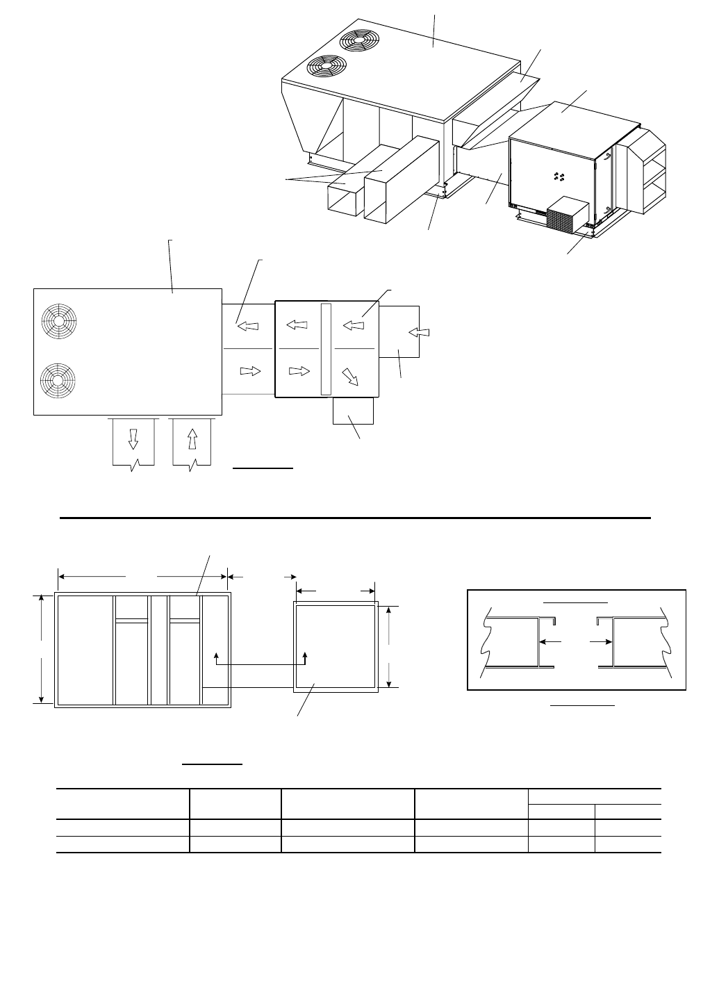
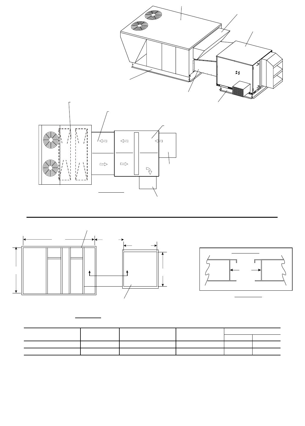
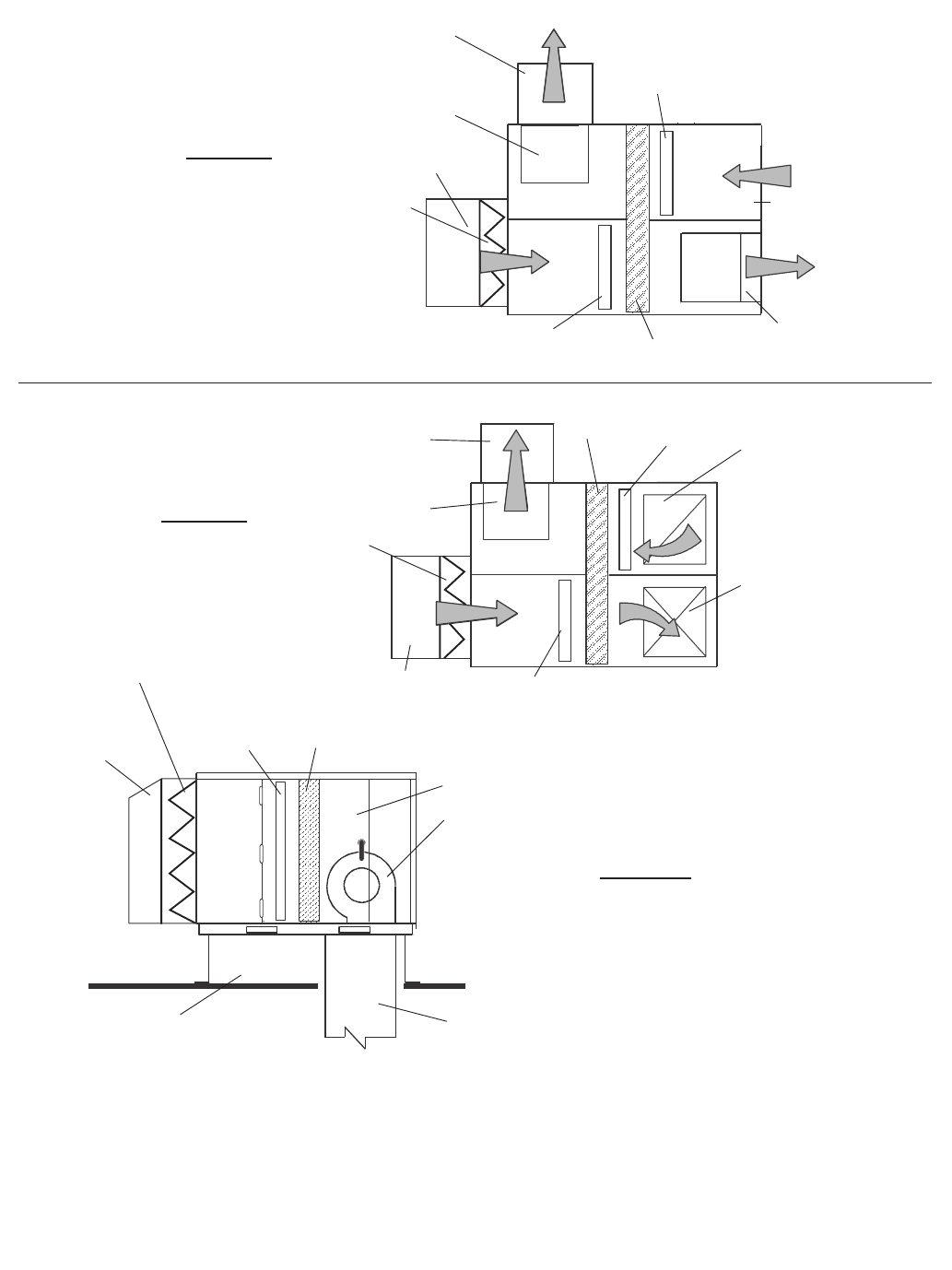
Fig. 45 — 62M Airflow in Stand-Alone Applications
45
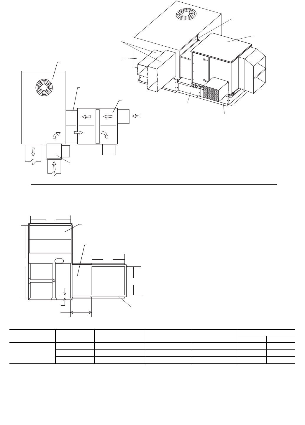
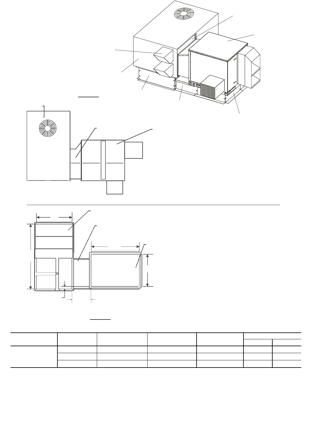
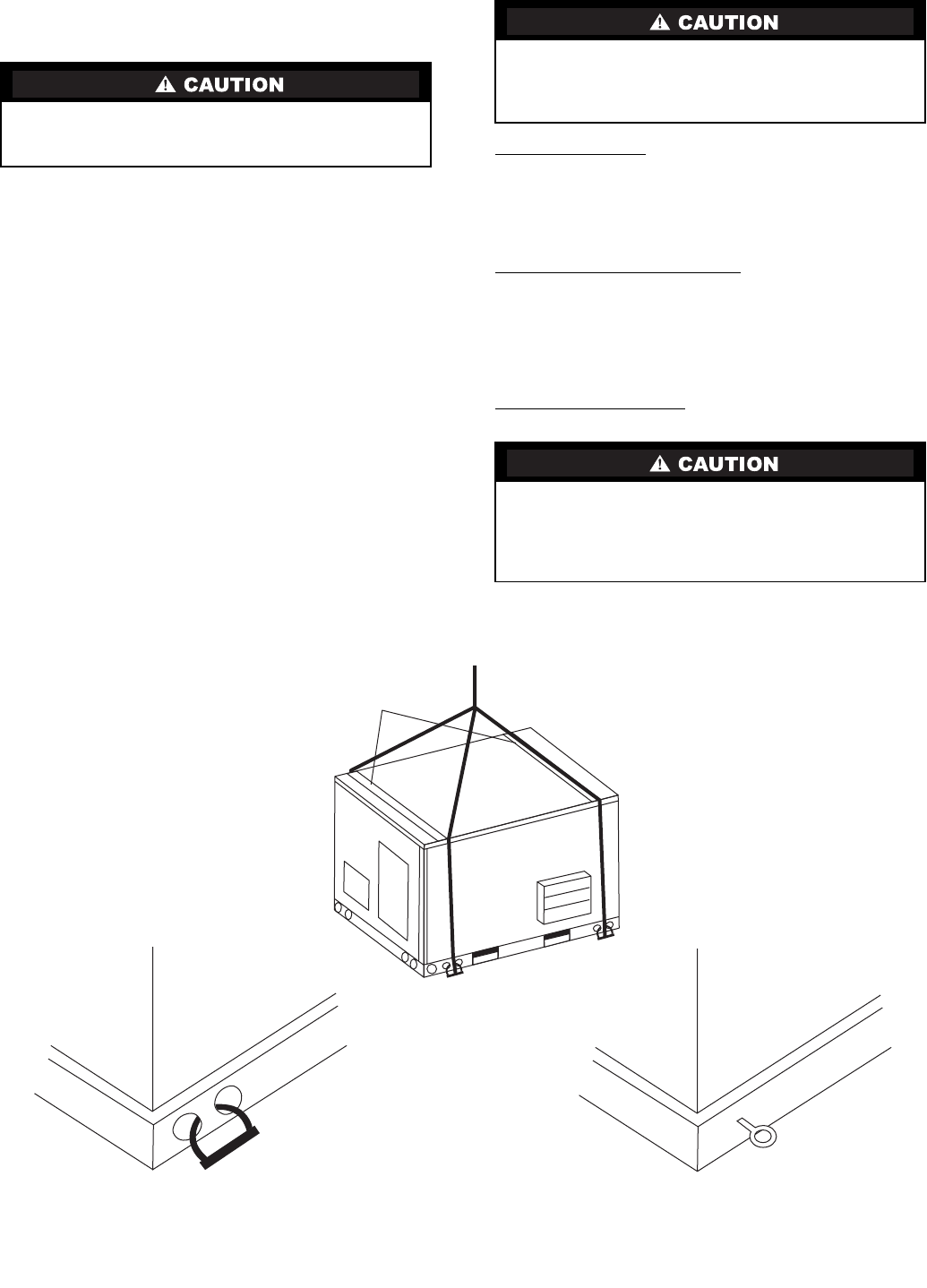
Step 3 — Rigging and Handling — To transfer the
unit from the shipping platform to the storage or installation
site, refer to the rigging label on the unit and these instructions.
Refer to Table 1 for ERV unit weights. Check lifting devices
for capacity constraints.
Hook rigging shackles through the holes or lifting eyes in
the ERV unit.
NOTE: Some 62M units have lifting eyes, some 62M units
have holes in the ERV base rail. See Fig. 46.
Connect lifting straps and spreader bars. See Fig. 46.
Spreader bars must be positioned to prevent cables from
rubbing against the ERV unit.
Carefully lift the ERV unit and set on ERV roof curb. Do
not drop the ERV unit onto the roof curb, as damage may
occur. Avoid twisting or uneven lifting of the unit. Never lift
the unit by the hoods or any means other than the provided
lifting holes or eyes.
MOUNTING THE ERV UNIT INDOORS — The ERV unit
can be mounted indoors. Follow all local and other applicable
building codes.
Locate the ERV Unit — Prior to locating the indoor ERV unit
consider the intake and exhaust duct accessibility to outside
walls or roof vents. When locating the ERV unit consider
required service clearances.
See Table 1 for unit weights to determine if building struc-
ture reinforcements are required.
Determine a Method for Mounting — The method for mount-
ing and securing the ERV unit to the building structure must be
field designed and installed. Mounting methods will vary
depending upon specific jobsite conditions.
NOTE: Hardware and pieces to secure ERV unit to the build-
ing structure must not interfere with the service clearances or
duct requirements for the unit.
Lift the ERV Unit in Place — Secure the ERV unit to the
building structure following all applicable local building codes.
All panels must be in place when rigging. Unit is not
designed for handling by fork truck. Damage to unit may
result.
All panels must be secured in place prior to lifting the ERV
unit in to place. Follow all local and other applicable codes
when lifting, locating and mounting the ERV unit. Damage
to unit may result.
Do not use the ERV duct system to support the ERV unit in
any way. Follow all local and applicable building codes
and manufacture and install the ductwork to the ERV unit
per the duct opening connections. Equipment damage or
personal injury may result.
Spreader Bars
Fig. 46 — Rigging Details
RIGGING FOR ERV INSTALLATION
RIGGING HOLES ERV BASE RAIL RIGGING LIFTING EYES
46
Table 1 — Physical Data
LEGEND
N/A — Not Applicable
*Add 10 in. to 62M040 units equipped with a preheater.
†Dimensions include outdoor air hoods.
**575-v motors are 1/3hp.
UNIT 62M 040 075 120 170 225 285
NOMINAL CAPACITY (cfm) 400 750 1200 1700 2250 2850
CAPACITY RANGE (cfm) 100-550 500-1000 1000-1400 1400-2000 2000-2500 2500-3200
MAXIMUM SHIPPING WEIGHT (lb)
Single-Wall Models 255 440 462 850 900 1000
Double-Wall Models 367 635 657 1135 1185 1285
MAXIMUM OPERATING WEIGHT (lb)
Single-Wall Models 235 400 422 790 840 940
Double-Wall Models 347 595 617 1075 1125 1225
62MB,MC INDOOR UNIT DIMENSIONS (in.)
Length* 29.75 43.25 43.25 62.63 62.63 62.63
Width 29.88 39.13 39.13 58.38 58.38 58.38
Height 29.75 37.88 37.88 48.88 48.88 48.88
62MD,ME OUTDOOR UNIT DIMENSIONS (in.)†
Length* 48.43 60.75 60.75 87.13 87.13 87.13
Width 31.24 50.13 55.13 69.38 69.38 69.38
Height 29.72 37.88 37.88 48.88 48.88 48.88
ROTARY ENERGY EXCHANGER
Type Enthalpy Lightweight Polymer with Silica Gel Desiccant Coating
Size (Diam. x Depth) (in.) 22.5 x 2 29.0 x 2 29.0 x 3 40.0 x 1.5 40.0 x 1.5 40.0 x 3
Nominal Drive Motor Hp N/AN/AN/A1/61/61/6
SUPPLY/EXHAUST AIR FAN
Qty…Type 2….Forward Curved Centrifugal
Drive Type Direct Adjustable Belt Drive
Fan Isolation Neoprene Pads
Wheel Dimensions (Diam. x Width) 5.5 x 5.5 9 x 7 9 x 7 12 x 12 12 x 12 12 x 12
Nominal Motor Hp 1/41/21122
FILTERS (optional)
Type 2-in. Pleated — 30%Efficiency
Exhaust Air...Qty...Size (L x W x D) (in.) 1….12 x 20 x 2 1….18 x 25 x 2 1….18 x 25 x 2 2….20 x 25 x 2 2….20 x 25 x 2 2….20 x 25 x 2
Outside Air...Qty...Size (L x W x D) (in.) 1….12 x 20 x 2 1….18 x 25 x 2 1….18 x 25 x 2 2….20 x 25 x 2 2….20 x 25 x 2 2….20 x 25 x 2
UNIT 62M 330 430 550 640 750 950
NOMINAL CAPACITY (cfm) 3300 4300 5500 6400 7500 9500
CAPACITY RANGE (cfm) 3000-3600 3600-5000 5000-6000 6000-6800 6500-8500 8500-10,500
MAXIMUM SHIPPING WEIGHT (lb)
Single-Wall Models 1300 1350 1440 1590 2650 2750
Double-Wall Models 1710 1760 1850 2000 3270 3370
MAXIMUM OPERATING WEIGHT (lb)
Single-Wall Models 1220 1270 1360 1510 2550 2650
Double-Wall Models 1630 1680 1770 1920 3170 3270
62MB,MC INDOOR UNIT DIMENSIONS (in.)
Length 73.13 73.13 73.13 73.13 108.3 108.3
Width 67.89 67.89 67.89 67.89 97.87 97.87
Height 65.21 65.21 65.21 65.21 77.4 77.4
62MD,ME OUTDOOR UNIT DIMENSIONS (in.)†
Length 100.88 100.88 100.88 100.88 143.45 143.45
Width 87.89 87.89 87.89 87.89 121.87 121.87
Height 65.21 65.21 65.21 65.21 77.4 77.4
ROTARY ENERGY EXCHANGER
Type Enthalpy Lightweight Polymer with Silica Gel Desiccant Coating
Size (Diam. x Depth) (in.) 56.2 x 1.5 56.2 x 1.5 56.2 x 3 56.2 x 3 68.0 x 3 68.0 x 3
Nominal Drive Motor Hp 1/21/21/21/21/4** 1/4**
SUPPLY/EXHAUST AIR FAN
Qty…Type 2...Forward Curved Centrifugal
Drive Type Adjustable Belt Drive
Fan Isolation Neoprene Pads
Wheel Dimensions (Diam. x Width) 15 x 15 15 x 15 15 x 15 15 x 15 18 x 18 18 x 18
Nominal Motor Hp 2357
1/271/210
FILTERS (optional)
Type 2-in. Pleated — 30%Efficiency
Exhaust Air...Qty...Size (L x W x D) (in.) 6….16 x 20 x 2 6….16 x 20 x 2 6….16 x 20 x 2 6….16 x 20 x 2 6….20 x 24 x 2 6….20 x 24 x 2
Outside Air...Qty...Size (L x W x D) (in.) 6….16 x 20 x 2 6….16 x 20 x 2 6….16 x 20 x 2 6….16 x 20 x 2 6….20 x 24 x 2 6….20 x 24 x 2
47
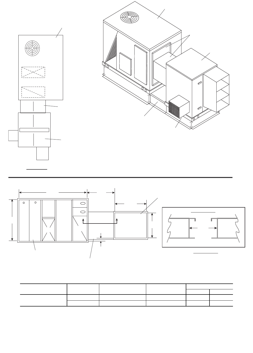
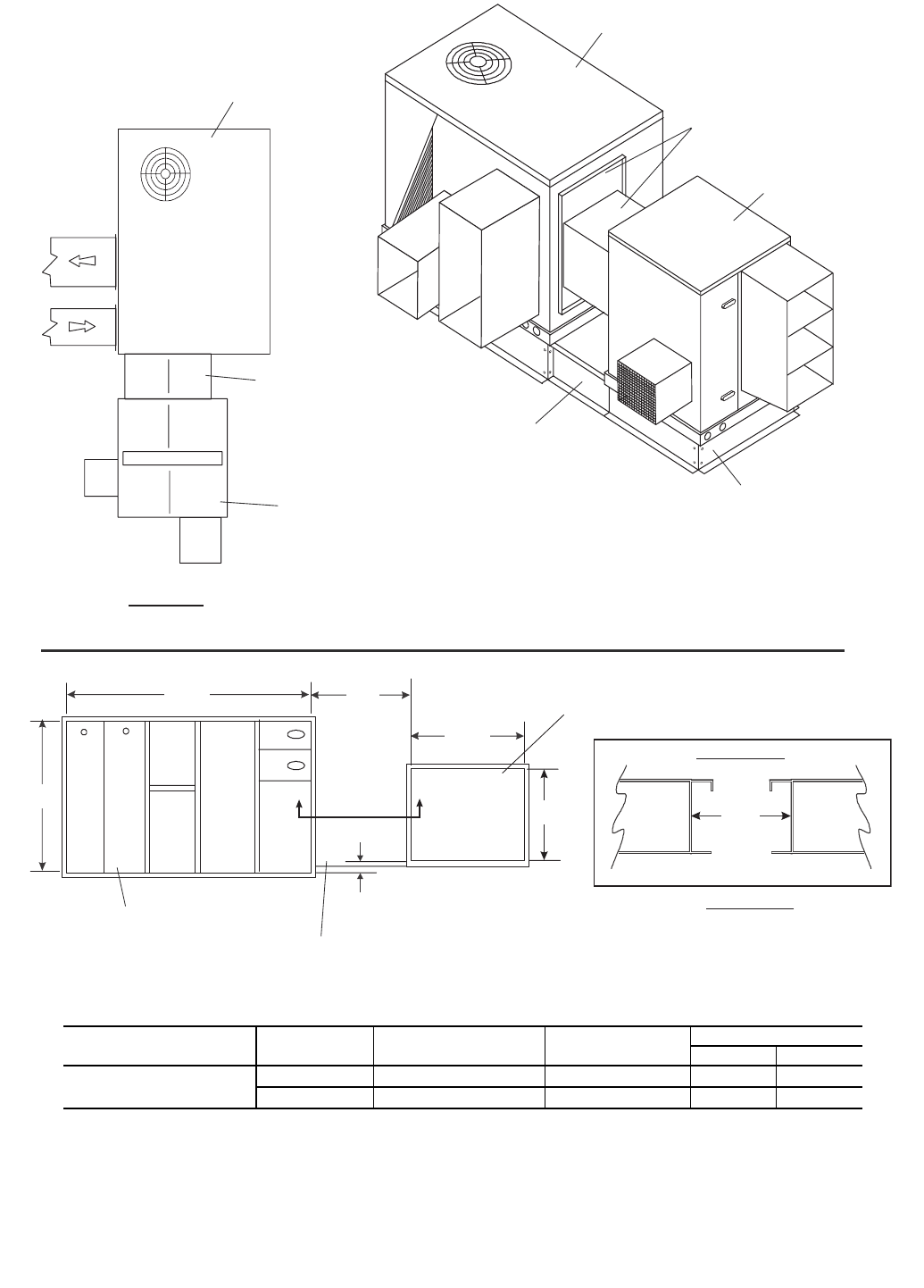
Step 4 — Installing ERV Transitions — When cou-
pling ERV units with Carrier rooftop units an ERV transition is
required to link the ERV unit and the Carrier rooftop unit
together.
ERV UNIT COUPLED WITH A 3 to 121/2TON HVAC
UNIT — Complete the following steps to install a transition to
a3to12
1/2ton rooftop unit.
1. Remove the HVAC unit filter door and set aside for later
use.
2. Remove the panel shipped on the HVAC unit covering
the return air chamber. This panel can be discarded.
3. The 62M ERV transition for 3 to 121/2ton rooftop units
includes a replacement panel to cover the return opening.
Install the replacement panel, with hood scoop attached,
onto the HVAC unit, over the return air chamber. Screw
in place. The return/exhaust scoop will cover part of the
return air opening in the HVAC unit.
NOTE: The standard transition does not seal tight around the
return air opening on the HVAC unit. This allows for some air
to flow back to the HVAC unit and some to be drawn back
through the ERV unit.
4. Slide the transition between the ERV unit and the HVAC
unit. Refer to Fig. 17-44 to orient the transition. Line up
the transition so that it covers the openings in the HVAC
unit and the ERV unit. The divider in the transition must
separate the supply and return openings in the ERV unit.
Screw the mating flanges of the transition to the ERV unit
through pre-punched holes. Caulk the seams watertight.
Screw the mating flanges on the other side of the transi-
tion to the new return air cover panel on the HVAC unit.
Caulk seams watertight.
5. On most models the filter access door shipped with the
HVAC unit will be reinstalled above the transition.
6. The transition includes a balancing damper to allow for
the desired separation of the return/exhaust air between
the ERV and HVAC units. This damper has a manual
adjustment. During balancing, this damper will be
adjusted to achieve desired exhaust cfm. The balancing
damper can be accessed through a separate door in the
transition or through the HVAC unit’s filter access door.
See Fig. 17-44.
Step 5 — Make Electrical Connections
POWER SUPPLY — The electrical characteristics of the
available power supply must agree with the unit nameplate
rating. Supply voltage must be within the limits shown. See
Tables 2 and 3 for electrical and configuration data.
ELECTRICAL CONNECTIONS — The ERV unit must
have its own electrical disconnect box. If the disconnect option
has not been ordered from the factory, it must be field supplied
and installed per local codes. See Tables 2 and 3.
If the ERV unit has an electric pre-heater factory installed, it
will be wired through the ERV unit disconnect.
NOTE: Most ERV units have electrical interlock safety
switches on the access doors, which will not allow the ERV
unit to operate if either of the access doors are opened.
Low Voltage Wiring — Wire low voltage per diagrams. For
coupled applications, there will be a brown and black wire in
the exhaust chamber, which must be tied into the HVAC unit’s
indoor fan so that when the indoor fan is activated, the ERV
unit will be activated.
48/50TJ, HJ 3 to 121/2Ton Rooftop Units with Economizers
— The brown and black wires can be plugged into the econo-
mizer jumper plug on the HVAC unit’s economizer harness.
Insert the brown wire from the ERV unit into terminal 4 in the
jumper plug and insert the black wire from the ERV unit into
terminal 3 in the jumper plug. See Fig. 47.
If the 3 to 121/2ton rooftop unit has an economizer in-
stalled, the economizer will have an end switch attached to the
economizer actuator. The end switch must be wired into the
ERV unit as shown in Fig. 48.
For ERV units coupled with units with factory-installed
economizers, (48/50TM, HJ 15 to 25 ton units 48/50HG, PG 15
to 25 ton units) the ERV transitions to these rooftop units in-
clude an economizer end switch. This switch mounts to the hub
of the economizer damper gear as shown in Fig. 49. Set the end
switch so that the ERV unit’s outside air blower is deactivated
during economizer mode.
For stand-alone units, the ERV unit is jumpered from termi-
nals 6 and 8 and 7 and 9, providing for continuous operation.
The ERV unit should be connected to an on-off device such as
aCO
2sensor.
High Voltage Wiring (Fig. 50-53) — Connect high voltage
wiring to the disconnect per Fig. 50, 52 and 53. Check blower
rotation direction and adjust if necessary.
Prior to performing service or maintenance operations on
the ERV unit, turn off and disconnect all power switches to
the unit. Be aware that there may be more than one discon-
nect switch. Electrical shock could cause serious personal
injury or death.
IMPORTANT: Only trained, qualified installers and
service technicians should install, wire, start-up and
service equipment.
48
Table 2 — Electrical Data Without VAV Option
LEGEND
*Fused disconnect only.
†Exhaust and supply fan motors are 230-1-60.
UNIT SIZE
62M
VOLTAGE
(V-Ph-Hz)
ERV WHEEL
FLA
EXHAUST AND SUPPLY MOTOR HEATER
SIZE
(kW)
POWER SUPPLY PRE-HEATER
(Optional)
FLA
DISCONNECT
(Optional)
NEC - FLA Hp FLA MCA MOCP Amps Fuse Size*
Amps
040
115-1-60 0.7 3.96
.6
— 9.27 9.90 12.87 — 30 12
2 26.64 31.64 31.64 17.39 40 30
230-1-60
0.3 1.74†
— 4.44 4.35 5.66 —
30
5
2 13.76 16.37 16.37 8.7 15
208/230-3-60 — 4.11 4.35 5.66 — 5
2 9.66 11.30 11.30 5.03 10
460-3-60 — 2.34 2.72 4.89 — 3
2 4.85 5.86 7.40 2.51 5
575-3-60 — 1.87 2.17 3.91 — 2
2 3.75 4.18 6.90 2.01 4
075
115-1-60 0.7 9.8
0.5
— 20.69 24.5 31.85 — 40 30
2 38.08 46.24 49.24 17.39 60 45
5 64.17 78.85 78.85 43.48 100 70
230-1-60
0.3
4.9
— 10.46 12.25 15.93 — 30 15
2 19.16 23.12 24.62 8.7 20
5 32.2 39.42 39.42 21.74 60 35
208/230-3-60 2.2
— 5.03 5.50 7.15 —
30
6
2 10.05 11.78 12.18 5.03 12
5 17.59 21.21 21.21 12.57 20
460-3-60 1.1
— 2.53 2.75 3.58 — 4
2 5.04 5.89 6.09 2.51 6
5 8.81 10.60 10.60 6.28 10
575-3-60 0.9
— 2.10 2.25 2.93 — 3
2 4.11 4.76 4.94 2.01 5
5 7.13 8.53 8.53 5.03 8
120
115-1-60 0.7 16
1
— 33.09 40.00 52.00 — 60 50
2 50.48 61.74 69.39 17.39 80 60
5 76.57 94.35 95.48 43.48 200 90
230-1-60
0.3
8
— 16.66 20.00 26.00 — 30 25
2 25.36 30.87 34.70 8.70 40 30
5 38.40 47.17 47.74 21.74 60 45
208/230-3-60 4.2
— 9.03 10.50 13.65 — 30 12
5 14.05 16.78 18.68 5.03 30 18
8 21.59 26.21 26.22 12.57 40 25
460-3-60 2.1
— 4.53 5.25 6.83 —
30
6
2 7.04 8.39 9.34 2.51 8
5 10.81 13.10 13.11 6.28 12
575-3-60 1.7
— 3.70 4.25 5.53 — 5
2 5.71 6.76 7.54 2.01 6
5 8.73 10.53 10.55 5.03 10
170
230-1-60
0.6
8
1
— 16.93 20.00 26.00 — 30 25
5 38.67 47.17 47.74 21.74 60 45
8 51.71 63.48 63.48 34.78 80 60
10 60.41 74.35 74.35 43.48 100 70
208/230-3-60 4.2
— 9.33 10.50 13.65 — 30 12
5 21.90 26.21 26.22 12.57 40 25
8 29.44 35.63 35.63 20.11 60 35
10 34.46 41.91 41.91 25.13 60 40
460-3-60 2.1
— 4.69 5.25 6.83 — 30 6
5 10.97 13.10 13.11 6.28 30 12
8 14.74 17.82 17.82 10.05 30 18
10 17.26 20.96 20.96 12.57 30 20
575-3-60 1.7
— 3.88 4.25 5.53 — 30 5
5 8.90 10.53 10.55 5.03 30 10
8 11.92 14.30 14.30 8.04 30 12
10 13.93 16.82 16.82 10.05 30 15
ERV — Energy Recovery Ventilator
FLA — Full Load Amps
Hp — Horsepower
MCA — Minimum Circuit Amps
MOCP — Maximum Overcurrent Protection
NEC — National Electric Code
N/A — Not Applicable

49
Table 2 — Electrical Data Without VAV Option (cont)
UNIT SIZE
62M
VOLTAGE
(V-Ph-Hz)
ERV WHEEL
FLA
EXHAUST AND SUPPLY MOTOR HEATER
SIZE
(kW)
POWER SUPPLY PRE-HEATER
(Optional)
FLA
DISCONNECT
(Optional)
NEC - FLA Hp FLA MCA MOCP Amps Fuse Size*
Amps
225
208/230-3-60
0.6
6.8
2
— 14.53 17.00 22.10 — 30 20
5 27.10 32.71 34.67 12.57 40 30
8 34.64 42.13 42.21 20.11 60 40
10 39.66 48.41 48.41 25.13 60 45
460-3-60 3.4
— 7.29 8.50 11.05 — 30 10
5 13.57 16.35 17.33 6.28 30 15
8 17.34 21.07 21.10 10.05 30 20
10 19.86 24.21 24.21 12.57 30 20
575-3-60 2.7
— 5.88 6.75 8.78 — 30 8
5 10.90 13.03 13.80 5.03 30 12
8 13.92 16.80 16.82 8.04 30 15
10 15.93 19.32 19.32 10.05 30 18
285
208/230-3-60
0.6
6.8
— 14.53 17.00 22.10 — 30 20
5 27.10 32.71 34.67 12.57 40 30
8 34.64 42.13 42.21 20.11 60 40
10 39.66 48.41 48.41 25.13 60 45
460-3-60 3.4
— 7.29 8.50 11.05 —
30
10
5 13.57 16.35 17.33 6.28 15
8 17.34 21.07 21.10 10.05 20
10 19.86 24.21 24.21 12.57
575-3-60 2.7
— 5.88 6.75 8.78 — 8
5 10.90 13.03 13.80 5.03 12
8 13.92 16.80 16.82 8.04 15
10 15.93 19.32 19.32 10.05 18
330
208/230-3-60
1.2
6.8
2
— 15.13 18.50 23.30 — 30 20
8 35.24 43.63 43.63 20.11 60 40
10 40.26 49.91 49.91 25.13 45
15 52.83 65.62 65.62 37.70 80 60
460-3-60 3.4
— 7.62 10.00 12.25 —
30
12
8 17.67 22.57 22.57 10.05 20
10 20.18 25.71 25.71 12.57 25
15 26.46 33.56 33.56 18.85 40 30
575-3-60 2.7
— 6.05 8.25 9.98 —
30
8
8 14.09 18.30 18.30 8.04 18
10 16.10 20.82 20.82 10.05 20
15 21.13 27.10 27.10 15.08 40 25
430
208/230-3-60
1.2
9.6
3
— 20.73 25.50 32.40 — 30
8 40.84 50.63 52.51 20.11 80 50
10 45.86 56.91 57.53 25.13
15 58.43 72.62 72.62 37.70 100 70
460-3-60 4.8
— 10.42 13.50 16.80 — 30 15
8 20.47 26.07 26.85 10.05 40 25
10 22.98 29.21 29.37 12.57
15 29.26 37.06 37.06 18.85 60 35
575-3-60 3.9
— 8.45 11.25 13.88 —
30
12
8 16.49 21.30 21.92 8.04 20
10 18.50 23.82 23.93 10.05
15 23.53 30.10 30.10 15.08 40 30
550
208/230-3-60
1.2
15.2
5
— 31.93 39.50 50.60 — 60 50
8 52.04 64.63 70.71 20.11 100 70
10 57.06 70.91 75.73 25.13
15 69.63 86.62 88.30 37.70 200 80
460-3-60 7.6
— 16.02 20.50 25.90 — 30 25
8 26.07 33.07 35.95 10.05
60 35
10 28.58 36.21 38.47 12.57
15 34.86 44.06 44.75 18.85 40
575-3-60 6.1
— 12.85 16.75 21.03 — 30 20
8 20.89 26.80 29.07 8.04 40 25
10 22.90 29.32 31.08 10.05 40 30
15 27.93 35.60 36.10 15.08 60 35
50
Table 2 — Electrical Data Without VAV Option (cont)
LEGEND
*Fused disconnect only.
†Exhaust and supply fan motors are 230-1-60.
UNIT SIZE
62M
VOLTAGE
(V-Ph-Hz)
ERV WHEEL
FLA
EXHAUST AND SUPPLY MOTOR HEATER
SIZE
(kW)
POWER SUPPLY PRE-HEATER
(Optional)
FLA
DISCONNECT
(Optional)
NEC - FLA Hp FLA MCA MOCP Amps Fuse Size†
Amps
640
208/230-3-60
1.2
22
7.5
— 45.53 56.50 72.70 — 100 70
8 65.64 81.63 92.81 20.11
200 90
10 70.66 87.91 97.83 25.13
15 83.23 103.62 110.40 37.70 110
460-3-60 11
— 22.82 29.00 36.95 — 60 35
8 32.87 41.57 47.00 10.05 45
10 35.38 44.71 49.52 12.57 60
15 41.66 52.56 55.80 18.85 80 50
575-3-60 9
— 18.65 24.00 30.45 — 40 30
8 26.69 34.05 38.49 8.04
60
35
10 28.70 36.57 40.50 10.05 40
15 33.73 42.85 45.53 15.08 45
750
208/230-3-60 2.5 22
— 46.83 58.13 74.00 — 100 70
10 71.96 89.54 99.13 25.13
200
90
15 84.53 105.25 111.70 37.70 110
20 97.09 120.95 124.26 50.26
460-3-60 1.2 11
— 23.36 29.00 36.95 — 60 35
10 35.93 44.71 49.52 12.57 45
15 42.21 52.56 55.80 18.85 80 50
20 48.49 60.41 62.08 25.13 80 60
575-3-60 1.4 9
— 19.53 24.25 30.65 — 40 30
10 29.58 36.82 40.70 10.05
60
40
15 34.61 43.10 45.73 15.08 45
20 39.64 49.38 50.76 20.11 50
950
208/230-3-60 2.5 30.8
10
— 64.46 80.13 102.60 —
200
100
10 92.25 114.86 130.39 27.79 125
15 106.15 132.23 144.29 41.69
20 120.04 149.60 158.18 55.58 N/A
460-3-60 1.2 14
— 29.36 36.50 46.70 — 60 45
10 41.93 52.21 59.27 12.57 80 50
15 48.21 60.06 65.55 18.85 80 60
20 54.49 67.91 71.83 25.13 100 70
575-3-60 1.4 11
— 23.53 29.25 37.15 — 60 35
10 33.58 41.82 47.20 10.05 45
15 38.61 48.10 52.23 15.08 80 50
20 43.64 54.38 57.26 20.11
ERV — Energy Recovery Ventilator
FLA — Full Load Amps
Hp — Horsepower
MCA — Minimum Circuit Amps
MOCP — Maximum Overcurrent Protection
NEC — National Electric Code
N/A — Not Applicable

51
Table 3 — Electrical Data With VAV Option
UNIT SIZE
62M*
VFD
VOLTAGE
V-Ph-Hz
ERV
WHEEL
FLA
VFD
CURRENT
INPUT
VALUE
AMP
EXHAUST AND SUPPLY
FAN MOTOR HEATER
SIZE
(kW)
POWER SUPPLY PRE-HEATER
(Optional)
FLA
DISCONNECT
(Optional)
NEC - FLA Hp FLA MCA MOCP Amps Fuse Size†
Amps
075
115-1-60 0.7 9.2
2.2
0.5
— 19.75 23.00 29.90 — 40 25
2 37.14 44.74 47.29 17.39 60 45
5 63.23 77.35 77.35 43.48 100 70
230-1-60**
0.3
5.2
— 11.05 13.02 16.93 — 30 15
2 19.74 23.89 25.62 8.70 25
5 32.79 40.19 40.19 21.74 60 40
208/230-3-60 2.8
— 6.26 7.03 9.14 —
30
8
2 11.28 13.31 14.17 5.03 12
5 18.82 22.74 22.74 12.57 20
460-3-60 1.5 1.1
— 3.24 3.65 4.74 — 5
2 5.76 6.79 7.25 2.51 6
5 9.53 11.50 11.50 6.28 10
575-3-60 2.1 0.9
— 4.41 5.13 6.67 — 6
2 6.42 7.64 8.68 2.01 8
5 9.43 11.41 11.69 5.03 10
120
115-1-60 0.7 16.6
4.2
1
— 34.55 41.50 53.95 — 80 50
2 51.94 63.24 71.34 17.39 100 70
5 78.03 95.85 97.43 43.48 200 90
230-1-60**
0.3
9.6
— 19.80 23.96 31.15 — 40 30
2 28.49 34.83 39.84 8.70 60 35
5 41.54 51.13 52.88 21.74 80 50
208/230-3-60 5.3
— 11.26 13.28 17.27 — 30 15
5 16.28 19.56 22.29 5.03 30 20
8 23.82 28.99 29.83 12.57 40 25
460-3-60 2.6 2.1
— 5.53 6.51 8.46 —
30
8
2 8.05 9.65 10.98 2.51 10
5 11.82 14.36 14.75 6.28 12
575-3-60 2.1 1.7
— 4.41 5.13 6.67 — 6
2 6.42 7.64 8.68 2.01 8
5 9.43 11.41 11.69 5.03 10
170
230-1-60**
0.6
9.6
4.2
1
— 20.10 23.96 31.15 — 40 30
5 41.84 51.13 52.88 21.74 80 50
8 54.88 67.44 67.44 34.98 80 60
10 63.57 78.31 78.31 43.48 100 70
208/230-3-60 5.3
— 11.56 13.28 17.27 — 30 15
5 24.12 28.99 29.83 12.57 40 25
8 31.66 38.41 38.41 20.11 60 35
10 36.69 44.70 44.70 25.13 60 40
460-3-60 2.6 2.1
— 5.70 6.51 8.46 —
30
8
5 11.98 14.36 14.75 6.28 12
8 15.75 19.08 19.08 10.05 17.5
10 18.26 22.22 22.22 12.57 20
575-3-60 2.1 1.7
— 4.58 5.13 6.67 — 6
5 9.61 11.41 11.69 5.03 10
8 12.62 15.18 15.18 8.04 15
10 14.63 17.69 17.69 10.05 17.5
225
208/230-3-60
0.6
8.2 6.8
2
— 17.39 20.57 26.74 — 40 25
5 29.95 36.28 39.31 12.57
60
35
8 37.49 45.70 46.85 20.11 45
10 42.52 51.99 51.99 25.13 50
460-3-60 4.2 3.4
— 8.82 10.42 13.54 — 30 12
5 15.11 18.27 19.82 6.28
40
17.5
8 18.88 22.98 23.59 10.05 20
10 21.39 26.12 26.12 12.57 25
575-3-60 3.6 2.7
— 7.66 8.97 11.66 —
30
10
5 12.68 15.26 16.69 5.03 15
8 15.70 19.03 19.71 8.04 17.5
10 17.71 21.54 21.72 10.05 20
52
Table 3 — Electrical Data With VAV Option (cont)
LEGEND
*The VAV option is not available on 62M040 units.
†Fused disconnect only.
**Exhaust and supply fan motors are 230-3-60.
UNIT SIZE
62M*
VFD
VOLTAGE
V-Ph-Hz
ERV
WHEEL
FLA
VFD
CURRENT
INPUT
VALUE
AMP
EXHAUST AND SUPPLY
FAN MOTOR HEATER
SIZE
(kW)
POWER SUPPLY PRE-HEATER
(Optional)
FLA
DISCONNECT
(Optional)
NEC - FLA Hp FLA MCA MOCP Amps Fuse Size†
Amps
285
208/230-3-60
0.6
8.2 6.8
2
— 17.39 20.57 26.74 — 40 25
5 29.95 36.28 39.31 12.57
60
35
8 37.49 45.70 46.85 20.11 45
10 42.52 51.99 51.99 25.13 50
460-3-60 4.2 3.4
— 8.82 10.42 13.54 —
30
12
5 15.11 18.27 19.82 6.28 17.5
8 18.88 22.98 23.59 10.05 20
10 21.39 26.12 26.12 12.57 40 25
575-3-60 3.6 2.7
— 7.66 8.97 11.66 —
30
10
5 12.68 15.26 16.69 5.03 15
8 15.70 19.03 19.71 8.04 17.5
10 17.71 21.54 21.72 10.05 20
330
208/230-3-60
1.2
8.2 6.8
2
— 17.99 20.57 26.74 — 40 25
8 38.09 45.70 46.85 20.11 60 45
10 43.12 51.99 51.99 25.13 50
15 55.69 67.70 67.70 37.70 80 60
460-3-60 4.2 3.4
— 9.15 10.42 13.54 — 30 12
8 19.20 22.98 23.59 10.05 20
10 21.71 26.12 26.12 12.57 40 25
15 28.00 33.98 33.98 18.85 30
575-3-60 3.6 2.7
— 7.83 8.97 11.66 —
30
10
8 15.87 19.03 19.71 8.04 18
10 17.88 21.54 21.72 10.05 20
15 22.91 27.82 27.82 15.08 40 25
430
208/230-3-60
1.2
11.3 9.6
3
— 24.03 28.13 36.56 — 60 35
8 44.14 53.26 56.67 20.11 80 50
10 49.16 59.54 61.69 25.13 60
15 61.73 75.25 75.25 37.70 100 70
460-3-60 5.6 4.8
— 12.07 14.06 18.28 — 30 18
8 22.12 26.63 28.33 10.05 40 25
10 24.63 29.77 30.85 12.57 30
15 30.91 37.62 37.62 18.85 60 35
575-3-60 4.8 3.9
— 10.29 12.05 15.66 —
30
15
8 18.33 22.10 23.71 8.04 20
10 20.34 24.61 25.72 10.05 25
15 25.37 30.90 30.90 15.08 40 30
550
208/230-3-60
1.2
17.8 15.2
5
— 37.16 44.53 57.89 — 80 50
8 57.26 69.66 78.00 20.11 100 70
10 62.29 75.95 83.02 25.13 80
15 74.85 91.65 95.59 37.70 200 90
460-3-60 9 7.6
— 18.73 22.40 29.11 — 40 25
8 28.78 34.96 39.17 10.05
60
35
10 31.30 38.10 41.68 12.57 40
15 37.58 45.96 47.96 18.85 45
575-3-60 7.6 6.1
— 15.83 18.97 24.66 — 30 20
8 23.87 29.02 32.70 8.04 40 30
10 25.88 31.54 34.71 10.05 30
15 30.91 37.82 39.74 15.08 60 35
ERV — Energy Recovery Ventilator
FLA — Full Load Amps
Hp — Horsepower
MCA — Minimum Circuit Amps
MOCP — Maximum Overcurrent Protection
NEC — National Electric Code
N/A — Not Applicable
VFD — Variable Frequency Drive
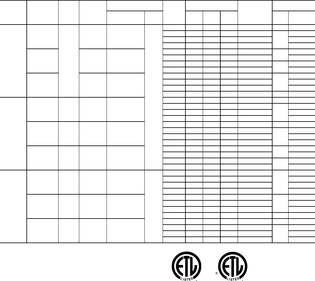
53
Table 3 — Electrical Data With VAV Option (cont)
LEGEND
*The VAV option is not available on 62M040 units.
†Fused disconnect only.
**Exhaust and supply fan motors are 230-3-60.
UNIT SIZE
62M*
VFD
VOLTAGE
V-Ph-Hz
ERV
WHEEL
FLA
VFD
CURRENT
INPUT
VALUE
AMP
EXHAUST AND SUPPLY
FAN MOTOR HEATER
SIZE
(kW)
POWER SUPPLY PRE-
HEATER
(Optional)
FLA
DISCONNECT
(Optional)
NEC - FLA Hp FLA MCA MOCP Amps Fuse Size†
Amps
640
208/230-3-60
1.2
26 22
7.5
— 53.61 65.10 84.64 — 100 80
8 73.72 90.24 104.74 20.11
200
100
10 78.75 96.52 109.77 25.13 100
15 91.31 112.23 122.33 37.70 110
460-3-60 12.9 11
— 26.65 32.29 41.98 — 60 40
8 36.70 44.86 52.03 10.05 50
10 39.21 48.00 54.55 12.57 80 50
15 45.50 55.85 60.83 18.85 60
575-3-60 11.5 9
— 23.62 28.71 37.33 —
60
35
8 31.66 38.76 45.37 8.04 45
10 33.67 41.28 47.38 10.05 45
15 38.70 47.56 52.40 15.08 80 50
750
208/230-3-60 2.5 26 22
— 54.91 65.10 84.64 — 100 80
10 80.05 96.52 109.77 25.13
200
100
15 92.61 112.23 122.33 37.70 110
20 105.18 127.93 134.90 50.26 125
460-3-60 1.2 12.9 11
— 27.20 32.29 41.98 — 60 40
10 39.76 48.00 54.55 12.57
80
50
15 46.05 55.85 60.83 18.85 60
20 52.33 63.71 67.11 25.13 60
575-3-60 1.4 11.5 9
— 24.50 28.71 37.33 — 60 35
10 34.55 41.28 47.38 10.05 45
15 39.58 47.56 52.40 15.08 80 50
20 44.61 53.84 57.43 20.11 50
950
208/230-3-60 2.5 34 30.8
10
— 70.86 85.00 110.50 —
200
110
10 98.65 119.74 138.29 27.79 125
15 112.55 137.11 152.19 41.69 N/A
20 126.44 154.48 166.08 55.58 N/A
460-3-60 1.2 16.5 14
— 34.28 41.15 53.49 —
80
50
10 46.85 56.85 66.06 12.57 60
15 53.13 64.71 72.34 18.85 70
20 59.41 72.56 78.62 25.13 100 70
575-3-60 1.4 14 11
— 29.63 35.12 45.66 — 60 45
10 39.68 47.69 55.71 10.05
80
50
15 44.71 53.97 60.74 15.08 60
20 49.73 60.25 65.76 20.11 60
ERV — Energy Recovery Ventilator
FLA — Full Load Amps
Hp — Horsepower
MCA — Minimum Circuit Amps
MOCP — Maximum Overcurrent Protection
NEC — National Electric Code
N/A — Not Applicable
VFD — Variable Frequency Drive
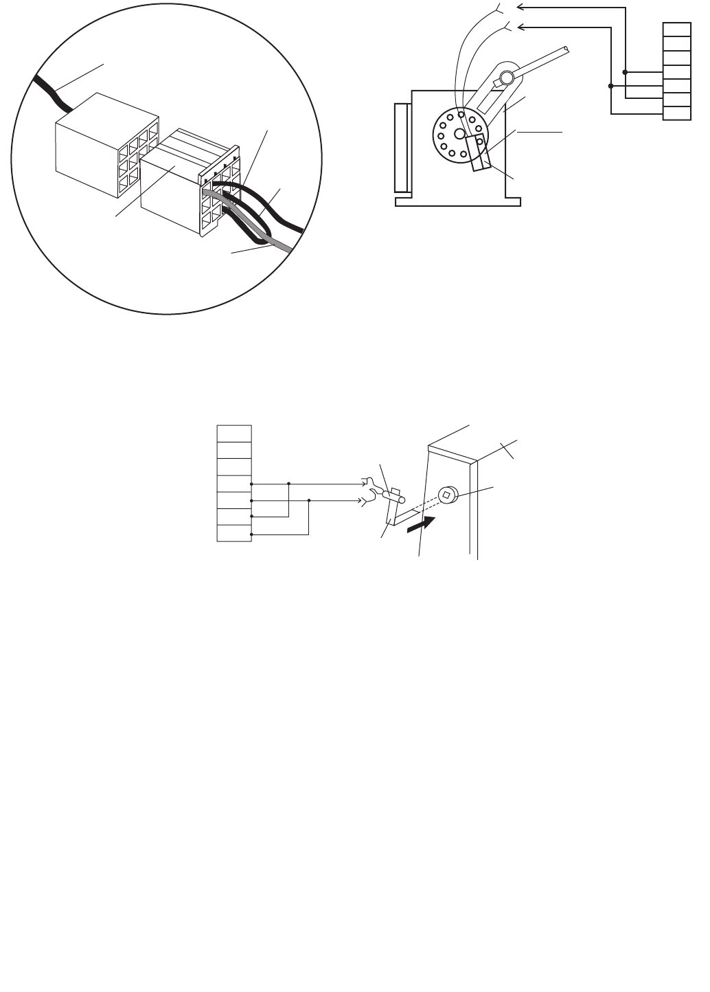
54
Economizer
harness/plug coming
from control box in
HVAC unit.
Jumper plug
shipped attached
economizer plug.
Brown
Black
Jumper
in plug
leave.
20
19
18
17
16
15
14
Actuator
(Motor)
Economizer
End switch
Important: Remove
and re-install through
end switch
20
19
18
17
16
15
14
Switch
Bracket
Economizer
Gear hub
Economizer
Switch
Fig. 47 — Jumper Plug Detail
Fig. 48 — Economizer End Switch Wiring
Fig. 49 — Economizer Switch Wiring
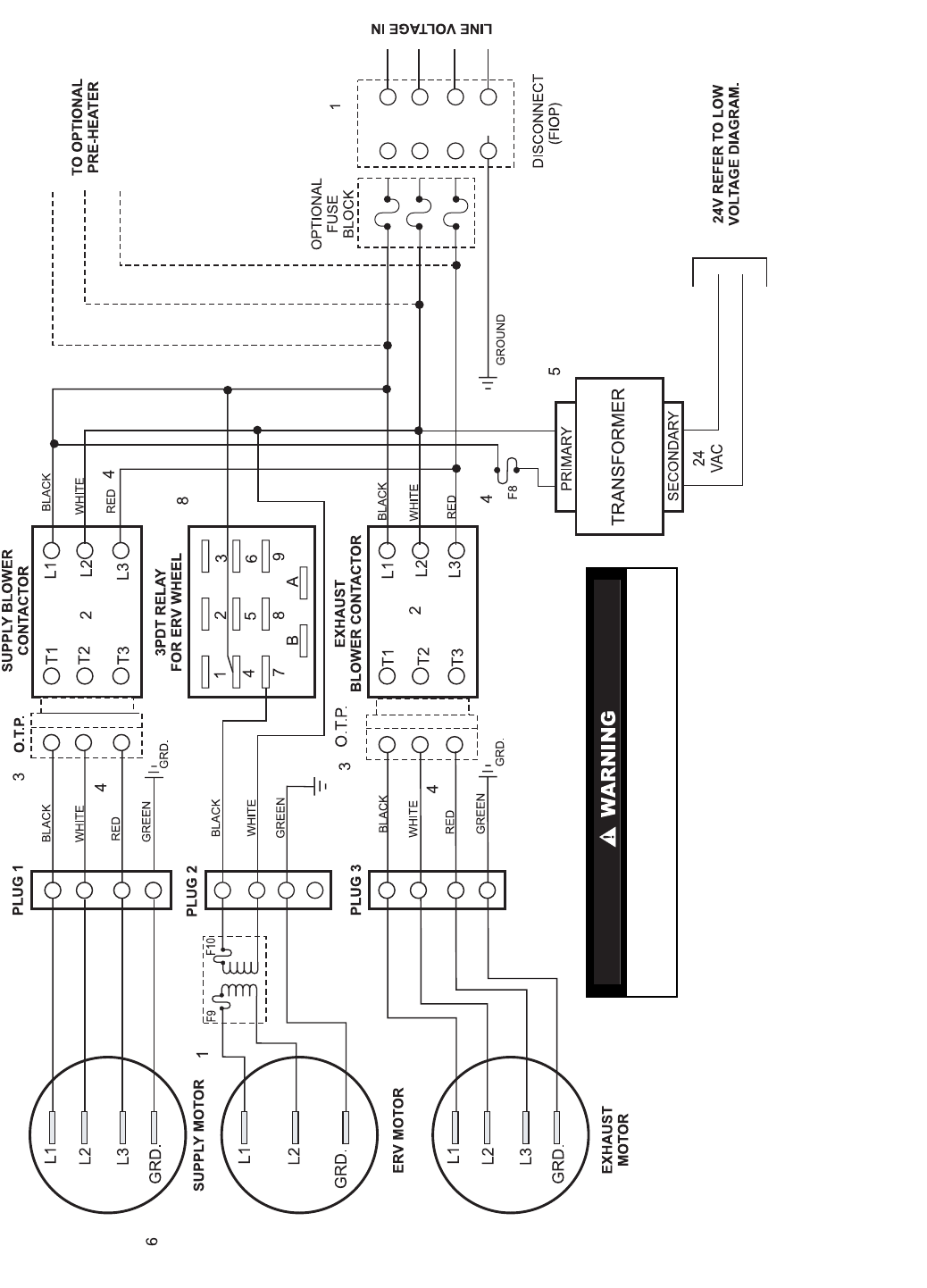
55
See Note
See Note
See Note
See Note
See Note
See Note
See Note
See Note
See Note
See Note
See Note
See Note
See Note
NOTES:
1. Transformer for ERV wheel only used on 460-v, 575-v, 115-v ERV units.
2. On single-phase ERV units the L3 and T3 terminals on supply blower contactor and exhaust blower contactor
are not used.
3. Overload thermal protection only used on 62M330-640 units with 5 hp and 71/2hp motors.
4. Red wire not used on 115-v, 208/230-v single-phase units.
5. Wire color determined by primary voltage and transformer type used.
6. On 115-v units, L2 becomes neutral. On 208/230-v single-phase units, L3 does not exist.
7. On units with total fusing greater than 30 amps, when pre-heater is installed and fused disconnect option is
selected, fusing will be separated. ERV and pre-heater will have separate fusing.
8. DPDT relay may be substituted. If so, pins 2, 5 and 8 will not exist.
9. Follow all local and other applicable codes.
10. Only qualified electrical contractors should install or service these ERV units.
11. For electrical characteristics (FLA, MCA)refer to charts in this booklet.
12. This diagram is for constant volume units.
Before performing service or maintenance operations on 62M unit,
turn off power switches to unit. Multiple switches may exist. Electrical
shock could cause personal injury or death.
LEGEND
3PDT — Three Pole, Dual Throw Relay FLA — Full Load Amps
DPDT — Dual Pole, Dual Throw Relay GRD — Ground
ERV — Energy Recovery Ventilator MCA — Minimum Circuit Amps
FIOP — Factory-Installed Option OTP — Overload Thermal Protection
Fig. 50 — Typical Wiring Schematic, High Voltage
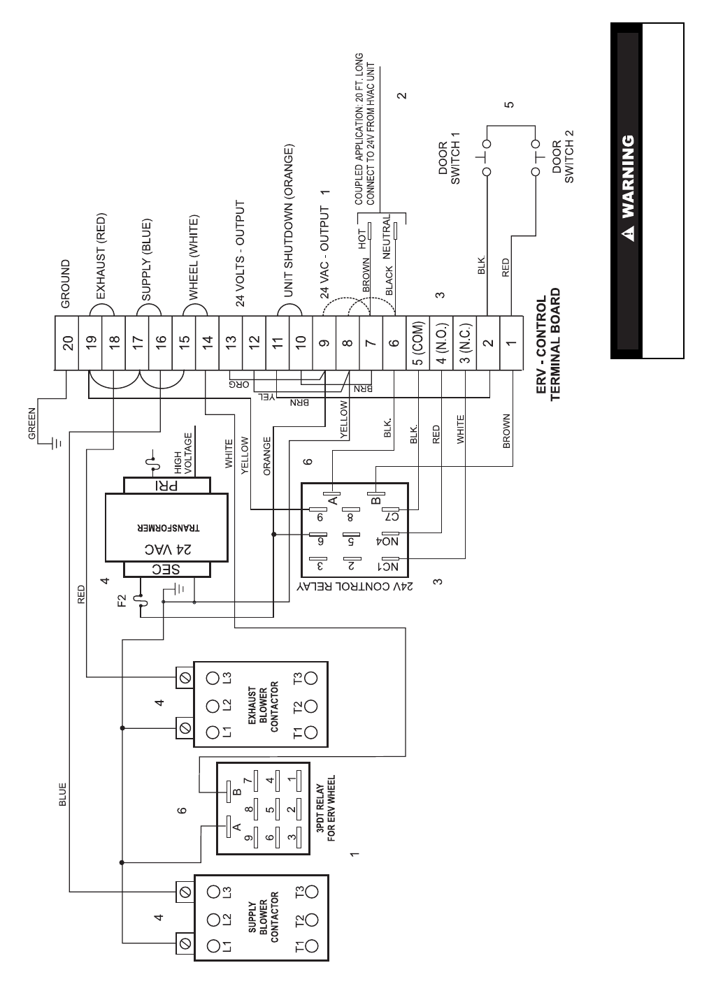
56
See Note
See Note
See Note
See Note
See Note
See Note
See Note
See Note
See Note
See Note
See Note
(Optional)
(Optional)
NOTES:
1. Stand-Alone Application: As shown, ERV will start when power is applied. Interrupt jumpers 6/8 and 7/9
for external control.
2. Jumpers between 6 and 8, and 7 and 9, will be factory added for stand-alone units.
3. Relay throughput: 1/3hp, 120 vac, 10 amp, 240 vac.
4. On 575-v units transformer may substitute internal breaker on secondary for fuse.
5. Door switches are optional.
6. DPDT relay may be substituted. If so, pins 2, 5 and 8 will not exist.
Before performing service or maintenance operations on 62M
unit, turn off power switches to unit. Multiple switches may exist.
Electrical shock could cause personal injury or death.
LEGEND
3PDT — Three Pole, Dual Throw Relay NC — Normally Closed
COM — Common NO — Normally Open
DPDT — Dual Pole, Dual Throw Relay PRI — Primary
ERV — Energy Recovery Ventilator SEC — Secondary
MCA — Minimum Circuit Amps
Fig. 51 — Typical Wiring Schematic, 24-V Control Circuit
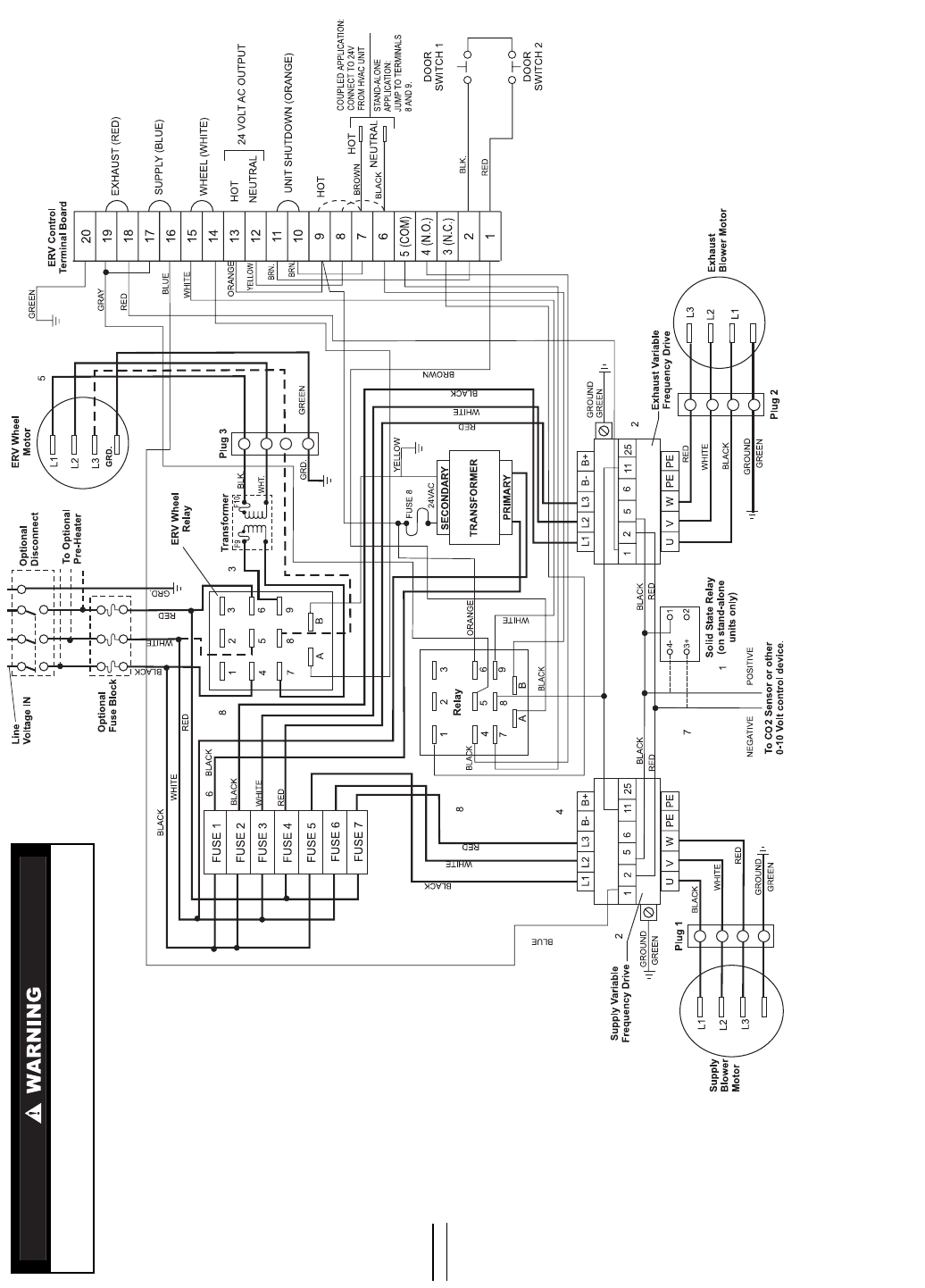
57
See Note
See Note
See Note
See Note
See Note
See Note
See Note
See Note
See Note
(OPTIONAL)
(OPTIONAL)
NOTES:
1. When the 62M unit is used in a stand-alone application, the solid-state relay will be added to activate
ERV at approximately 2 volts. CO2sensor output signal is sent to relay. Coupled units are activated
through HVAC unit.
2. Supply and Exhaust Variable Frequency Drive (VFD)terminals no. 25 and no. 2 can be used as a
4 to 20 mA power control source, if desired.
3. Transformer not necessary on all 62M750,950 units.
Before performing service or maintenance operations on 62M unit, turn off power
switches to unit. Multiple switches may exist. Electrical shock could cause personal
injury or death.
4. Variable frequency drives are sensitive to the polarity of a 0 to 10 volt DC control signal. If the control
source is acting properly and the voltage variance can be detected on the proper leads of the VFD,
reverse the leads and the controller will respond.
5. Three-phase motor on all 62M750,950 units.
6. Color determined by primary voltage: Red — 200 vac, Orange — 230 vac, Black — 460 vac.
7. 0 to 10 volt and 4 to 20 mA inputs are polarity sensitive. Reverse leads if signal fails to update controller.
8. DPDT relay may be substituted. If so, pins 2, 5 and 8 will not exist.
LEGEND
WIRING LEGEND
COM — Common
DPDT — Dual Pole, Dual Throw Relay
ERV — Energy Recovery Ventilator
GRD — Ground
NC — Normally Closed
NO — Normally Open
High Voltage
Low Voltage
Fig. 52 — Typical Wiring Schematic, High/Low Voltage with Variable Air Volume Option
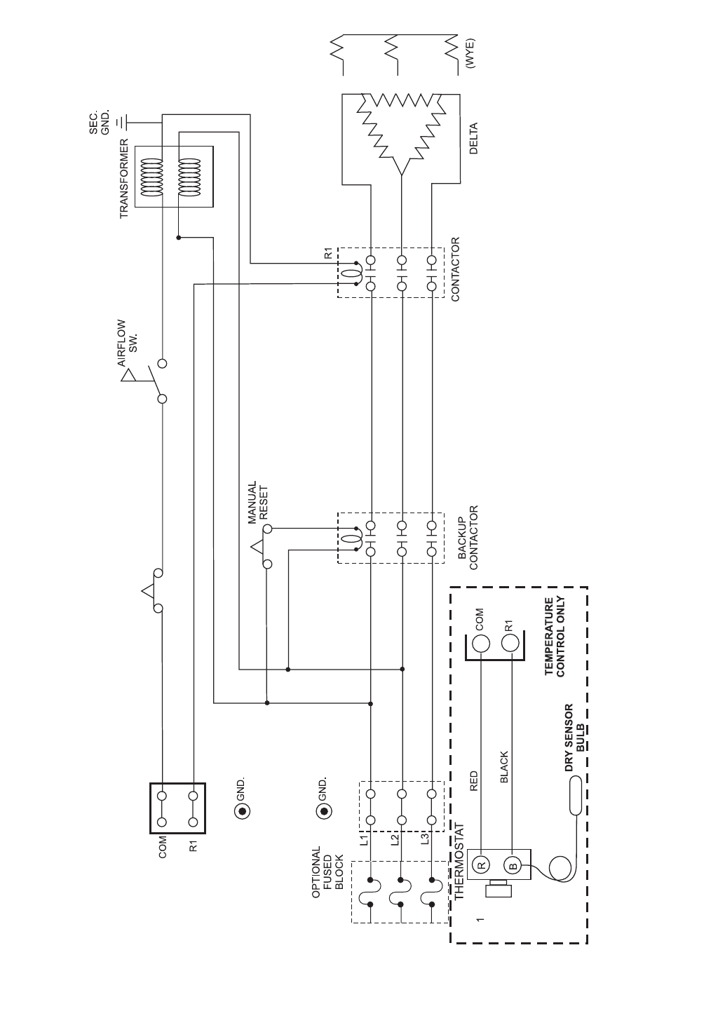
58
See Note
DISCONNECT
(FIOP)
NOTES:
1. Thermostat is factory set at –5 degrees. Range is –30 to 100 F.
2. MInimum airflow is .05 in. wg.
Fig. 53 — Typical Wiring Schematic, Optional Preheat High Voltage and Control Circuits
59
START-UP
Use the following information and the Start-Up Checklist
on page CL-1 to check unit PRIOR to start-up.
Unit Preparation — Check that the unit has been in-
stalled in accordance with these installation instructions and all
applicable codes.
Check all fasteners and set screws for tightness. This is
critical for bearings and fan wheels. Also, if dampers are not
motorized, check that they open and close without binding.
Internal Wiring — Check all electrical connections in the
control box. Tighten as required.
Rain Hoods — Some ERV units will require the outside
air and/or exhaust hood to be field installed. Caulk coupled
flanges and screw to ERV unit.
NOTE: Units for indoor applications will not have rain hoods.
The outside air hood will include aluminum water entrain-
ment filters, which should be in place prior to starting the unit.
Energy Recovery Wheel
DRIVE BELT — Turn the energy recovery wheel by hand to
verify free operation. Inspect the belt, which drives the energy
wheel rotation. Make sure the belt rides smoothly through the
pulley and over the wheel rim.
AIR SEALS — Check that the air seals, located around the
outside of the wheel and across the center, on both sides of
wheel, are secure and in good condition. Air seals which are
too tight will prevent proper rotation of the energy recovery
wheel. Re-check the air seals for tightness.
Air seal clearance may be checked by placing a sheet of
paper, like a feeler gage, against the wheel face. To adjust the
air seals, loosen all eight seal retaining screws. These screws
are located on the bearing support that spans the length of the
cassette through the wheel center. Tighten the screws so the air
seals tug slightly on the sheet of paper as the wheel is turned.
Replace the access door and apply power. Observe that the
wheel rotates freely. If the wheel does not rotate or is binding,
remove the cassette and adjust.
Blower Rotation — First, hand-rotate the blower to en-
sure that the wheel is not rubbing against the scroll. If the
blower is rotating in the wrong direction, the ERV unit will
move some air, but will not perform properly.
To change the rotation, turn the power off and use the
following procedure:
• Single-phase units — Rewire the motor per the instruc-
tions located on the motor.
• Three-phase units — Interchange any two power leads.
This can be done at the motor starter.
Airflow Settings and Adjustments — Most ERV
units have factory-installed airflow test ports, which allow the
balancer of the job to easily measure the static pressure across
the ERV wheel, and thus the system airflow cfm levels. The
static is measured on both the supply and return sides of the
wheel. See Fig. 54-56.
To achieve the highest level of effectiveness, the airflow
across the supply and return should be equal.
FACTORY SETTING — The ERV unit is factory set to
achieve the maximum airflow cfm within the cabinet’s range.
For example, a 62M170 unit has a range of 1,400 to 2,000 cfm
airflow, and when shipped will be setup to achieve the
2,000 cfm airflow level. See Fig. 57-80.
CURVE SELECTION — Refer to the fan curve for the ERV
unit being used for the application. See Fig. 57-80. Knowing
the outside air intake cfm required and the external static
pressure on the application, select the fan curve desired. The
fan curve will indicate how to set the blower motor pulley to
achieve the desired cfm level. If the job requirements are the
same as the maximum ERV unit setup, then no blower adjust-
ments are required.
ADJUST THE ERV BLOWER SPEED — If jobsite condi-
tions require blower speeds other than the factory setting, then
theERVblower(s)willhavetobeadjusted.Thefancurvewill
specify the number of turns to be made to the adjustable pulley
on the blower motor. See Fig. 57-80.
Belt Drive Motors — Check pulley alignment and belt tension
prior to set up. To change the speeds of the blowers:
1. Shut off power supply and tag disconnect.
2. Loosen belt tension.
3. Loosen adjustable (movable) pulley flange set screw. See
Fig. 81.
4. Screw adjustable pulley side toward the fixed side to
increase speed or away from fixed side to decrease speed.
Increasing speed increases load on motor. Do not exceed
maximum load for motor.
5. Set adjustable pulley side at nearest keyway of pulley hub
and tighten set screw. See fan curves for speed change for
each turn of the adjustable pulley.
Aligning Blower and Motor Pulleys — It is important that
the pulleys be exactly in line with one another. See Fig. 82.
1. Loosen blower pulley set screw.
2. Align pulleys per illustration. Motor and blower shafts
must be parallel.
3. Tighten pulley set screws.
Adjust Belt Tension — Loosen blower motor mounting nuts.
and slide motor mounting plate away from fan scroll for proper
belt tension (1/2-in.deflectionwith7to10lbofforce.)
MEASURE MOTOR VOLTAGE, AMPERAGE AND FAN
RPM — Measure and record the input voltage and motor
amperage(s). To measure the fan rpm, the blower door will
need to be opened. Minimize measurement time because the
motor may over-amp with the door removed. Do not operate
units with access doors/panels open as the motors will over-
load. With the blower door closed, compare measured amps to
the motor nameplate full load amps and correct if the ERV unit
is over-amping.
BELT MAINTENANCE — Premature belt failures are fre-
quently caused by improper belt tension (either too tight or too
loose), or misaligned pulleys. The proper tension for operating
a V-belt is the lowest tension at which the belts will not slip at
peak load conditions. Check belt tension two weeks after start-
up and periodically thereafter. It is very important that the drive
pulleys remain in proper alignment after adjustments are made.
Misalignment of pulleys will result in premature belt wear,
noise, vibration, and power loss. Maintain belts and motors
through the provided access panels. Refer to Fig. 82.
Text continued on page 74.
Do not operate the ERV unit without the filters and bird-
screens installed, which prevent foreign objects from enter-
ing the unit.
60
0.2
0.3
0.4
0.5
0.6
0.7
0.8
200 400 600 800 1000 1200 1400
Airflow (cfm)
Pressure Drop (in. wg)
62M040
62M075
62M120
0.4
0.5
0.6
0.7
0.8
0.9
1
1.1
1.2
1000 1200 1400 1600 1800 2000 2200 2400 2600 2800 3000 3200 3400 3600 3800 4000 4200 4400 4600 4800 5000
Airflow (cfm)
Pressure Drop (in. wg)
62M170,225 62M285
62M330,430
Fig. 55 — 62M170-430 ERV Wheel Pressure Drop*
Fig. 54 — 62M040-120 ERV Wheel Pressure Drop*
*Data based on measurements taken using optional airflow test ports.
*Data based on measurements taken using optional airflow test ports.
61
0.5
0.6
0.7
0.8
0.9
1
1.1
1.2
5000 5500 6000 6500 7000 7500 8000 8500 9000 9500 10000 10500 11000
Airflow (cfm)
Pressure Drop (in. wg)
62M550,640 62M750,950
Fig. 56 — 62M550-950 ERV Wheel Pressure Drop* (cont)
*Data based on measurements taken using optional airflow test ports.
62
NOTE: Fan data includes pressure drop for 30%efficient 2-in. filters.
NOTE: Fan data includes pressure drop for 30%efficient 2-in. filters.
External Static Pressure (in. wg)
0
100
200
300
400
500
600
0.00 0.20 0.40 0.60 0.80 1.00 1.20 1.40 1.60
Airflow (cfm)
Supply Air High Speed
Supply Air Speed Three
Supply Air Speed Two
Supply Air Low Speed
AIirflow (cfm)
External Static Pressure (in. wg)
0
100
200
300
400
500
600
0.00 0.20 0.40 0.60 0.80 1.00 1.20 1.40 1.60
Exhaust Air High Speed
Exhaust Air Speed Three
Exhaust Air Speed Two
Exhaust Air Low Speed
Fig. 57 — 62M040 Supply Air Fan Performance Curves
Fig. 58 — 62M040 Exhaust Air Fan Performance Curves
NOTE: Fan data includes pressure drop for 30%efficient 2-in. filters.
63
0
200
400
600
800
1000
1200
1400
0.1 0.3 0.5 0.7 0.9
Externa l St atic (in. w
g
)
Airflow (cfm)
1112 rpm: 2 turns
1058 rpm: 3 turns
1002 rpm: 4 turns
942 rpm: 5 turns
0
200
400
600
800
1000
1200
0.1 0.2 0.3 0.4 0.5 0.6 0.7 0.8 0.9
113 6 rpm: 2 turns
1081 rpm: 3 turns
1010 rpm: 4 turns
946 rpm: 5 turns
Airflow (cfm)
External Static (in. w
g
)
NOTE: Fan data includes pressure drop for 30%efficient 2-in. filters.
NOTE: Fan data includes pressure drop for 30%efficient 2-in. filters.
Fig. 59 — 62M075 Supply Air Fan Performance Curves
Fig. 60 — 62M075 Exhaust Air Fan Performance Curves
64
375
575
775
975
11 75
1375
1575
0.2 0.4 0.6 0.8 1
1448 rpm: 2 turns
1315 rpm: 3 turns
1277 rpm: 4 turns
1194 rpm: 5 turns
External Static (in. wg)
Airflow (cfm)
275
475
675
875
1075
1275
1475
0.2 0.4 0.6 0.8 1.0
1399 rpm: 2 turns
1332 rpm: 3 turns
1244 rpm: 4 turns
1162 rpm: 5 turns
Airflow (cfm)
External Static (in. wg)
NOTE: Fan data includes pressure drop for 30%efficient 2-in. filters.
NOTE: Fan data includes pressure drop for 30%efficient 2-in. filters.
Fig. 61 — 62M120 Supply Air Fan Performance Curves
Fig. 62 — 62M120 Exhaust Air Fan Performance Curves
65
1000
1200
1400
1600
1800
2000
2200
2400
2600
2800
0.2 0.4 0.6 0.8 1
1121 rpm: 3 turns
1074 rpm: 4 turns
1017 rpm: 5 turns
937 rpm: 6 turns
External Static (in. wg)
Airflow (cfm)
1000
1200
1400
1600
1800
2000
2200
2400
2600
0.2 0.4 0.6 0.8 1
1068 rpm: 3 turns
1045 rpm: 4 turns
1018 rpm: 5 turns
977 rpm: 6 turns
External Static (in. wg)
Airflow (cfm)
NOTE: Fan data includes pressure drop for 30%efficient 2-in. filters.
NOTE: Fan data includes pressure drop for 30%efficient 2-in. filters.
Fig. 63 — 62M170 Supply Air Fan Performance Curves
Fig. 64 — 62M170 Exhaust Air Fan Performance Curves
66
1000
1500
2000
2500
3000
0.20.40.60.8 1
1159 rpm: 3 turns
1114 rpm: 4 turns
1054 rpm: 5 turns
External Static (in. wg)
Airflow (cfm)
1000
1500
2000
2500
3000
0.2 0.4 0.6 0.8 1
1077 rpm: 3 turns
1052 rpm: 4 turns
1024 rpm: 5 turns
964 rpm: 6 turns
External Static (in. wg)
Airflow (cfm)
NOTE: Fan data includes pressure drop for 30%efficient 2-in. filters.
NOTE: Fan data includes pressure drop for 30%efficient 2-in. filters.
Fig. 65 — 62M225 Supply Air Fan Performance Curves
Fig. 66 — 62M225 Exhaust Air Fan Performance Curves
67
1000
1500
2000
2500
3000
3500
0.1 0.3 0.5 0.7 0.9 1.1
1186 rpm: 2 turns
1109 rpm: 3 turns
1057 rpm: 4 turns
1010 rpm: 5 turns
External Static (in. wg)
Airflow (cfm)
1000
1500
3000
3500
0.1 0.3 0.5 0.7 0.9 1.1
1193 rpm: 2 turns
1147 rpm: 3 turns
1097 rpm: 4 turns
1062 rpm: 5 turns
External Static (in. wg)
Airflow (cfm)
2500
2000
NOTE: Fan data includes pressure drop for 30%efficient 2-in. filters.
NOTE: Fan data includes pressure drop for 30%efficient 2-in. filters.
Fig. 67 — 62M285 Supply Air Fan Performance Curves
Fig. 68 — 62M285 Exhaust Air Fan Performance Curves
68
2000
2500
3000
3500
4000
4500
0.10 0.20 0.30 0.40 0.50
833 rpm: 2 turns
803 rpm: 3 turns
763 rpm: 4 turns
Externa l Static (in. w
g
)
Airflow (cfm)
2000
2200
2400
2600
2800
3000
3200
3400
3600
3800
4000
0.13 0.20 0.30 0.40 0.50
842 rpm: 2 turns
808 rpm: 3 turns
770 rpm: 4 turns
Externa l Static (in. w
g
)
Airflow (cfm)
NOTE: Fan data includes pressure drop for 30%efficient 2-in. filters.
NOTE: Fan data includes pressure drop for 30%efficient 2-in. filters.
Fig. 69 — 62M330 Supply Air Fan Performance Curves
Fig. 70 — 62M330 Exhaust Air Fan Performance Curves
69
2500
3000
3500
4000
4500
5000
5500
0. 20 0. 40 0. 60 0. 80 1. 00
962 rpm: 3 turns
942 rpm: 4 turns
891 rpm: 5 turns
External Static (in. wg)
Airflow (cfm)
2500
3000
3500
4000
4500
5000
5500
0. 20 0. 40 0. 6 0 0. 80 1. 00
871 rpm: 4 turns
891 rpm: 5 turns
External Static (in. wg)
Airflow (cfm)
NOTE: Fan data includes pressure drop for 30%efficient 2-in. filters.
NOTE: Fan data includes pressure drop for 30%efficient 2-in. filters.
Fig. 71 — 62M430 Supply Air Fan Performance Curves
Fig. 72 — 62M430 Exhaust Air Fan Performance Curves
70
2000
2500
3000
3500
4000
4500
5000
5500
6000
6500
0.2 0.4 0.6 0.8 1.0 1.2
1109 rpm: 2 turns
1068 rpm: 3 turns
1014 rpm: 4 turns
968 rpm: 5 turns
External Static (in. wg)
Airflow (cfm)
2000
2500
3000
3500
4000
4500
5000
5500
6000
6500
0 .3 0 .4 0 .6 0 .8 1 .0 1.2
1109 rpm: 2 turns
1049 rpm: 3 turns
998 rpm: 4 turns
947 rpm: 5 turns
Airflow (cfm)
Externa l Static (in. wg)
NOTE: Fan data includes pressure drop for 30%efficient 2-in. filters.
NOTE: Fan data includes pressure drop for 30%efficient 2-in. filters.
Fig. 73 — 62M550 Supply Air Fan Performance Curves
Fig. 74 — 62M550 Exhaust Air Fan Performance Curves
71
5000
5500
6000
6500
7000
7500
0.25 0.45 0.65 0.85 1.00 1.20
1256 rpm: 2 turns
1174 rpm: 3 turns
1150 rpm: 4 turns
Externa l Static (in. wg)
Airflow (cfm)
5000
5500
6000
6500
7000
7500
8000
0.4 0.5 0.6 0.7 0.9
1202 rpm : 0 turns
1152 rpm: 1 turn
1123 rpm: 2 turns
1096 rpm: 3 turns
Externa l Static (in. wg)
Airflow (cfm)
NOTE: Fan data includes pressure drop for 30%efficient 2-in. filters.
NOTE: Fan data includes pressure drop for 30%efficient 2-in. filters.
Fig. 75 — 62M640 Supply Air Fan Performance Curves
Fig. 76 — 62M640 Exhaust Air Fan Performance Curves
72
5500
6000
6500
7000
7500
8000
8500
9000
9500
0.10 0.30 0.50 0.70 0.90 1.10
906 rpm: 0 turns
870 rpm: 1 turns
847 rpm: 2 turns
821 rpm: 3 turns
807 rpm: 4 turns
Externa l Static (in. wg)
Airflow (cfm)
5500
6000
6500
7000
7500
8000
8500
9000
0.3 0.5 0.7 0.9 1.1
923 rpm : 0 turns
898 rpm: 1 turn
862 rpm: 2 turns
844 rpm: 3 turns
813 rpm: 4 turns
Externa l Static (in. w
g
)
Airflow (cfm)
NOTE: Fan data includes pressure drop for 30%efficient 2-in. filters.
NOTE: Fan data includes pressure drop for 30%efficient 2-in. filters.
Fig. 77 — 62M750 Supply Air Fan Performance Curves
Fig. 78 — 62M750 Exhaust Air Fan Performance Curves
73
6500
7000
7500
8000
8500
9000
9500
10000
10500
11 000
11 500
0.10 0.30 0.50 0.70 0.90 1.10
966 rpm: 3 turns
896 rpm: 4 turns
831 rpm: 5 turns
Airflow (cfm)
Externa l Stat ic (in. wg)
7000
7500
8000
8500
9000
9500
10000
10500
11000
0.3 0.5 0.7 0.9 1.1
1024 rpm: 3 turns
962 rpm: 4 turns
929 rpm: 5 turns
Airflow (cfm)
External Stat ic (in. wg)
NOTE: Fan data includes pressure drop for 30%efficient 2-in. filters.
NOTE: Fan data includes pressure drop for 30%efficient 2-in. filters.
Fig. 79 — 62M950 Supply Air Fan Performance Curves
Fig. 80 — 62M950 Exhaust Air Fan Performance Curves
74
Variable Air Volume Option — This option can be
used in conjunction with the CO2sensor option (ordered
separately). Outside air and exhaust air blower speeds are
independently controlled by variable frequency drives and
modulated based upon space occupancy, which can be
measured by CO2. The more people in the space the greater the
CO2levels, the more outside air is introduced. This option
eliminates over ventilating the space in less than full condi-
tions. The ERV unit has completely different electrical charac-
teristics when used with a variable air volume option. Refer to
Tables 2 and 3.
Operating Sequence
OCCUPIED MODE — While in occupied mode, the 62M
ERV will operate per the ERV Timer option (scheduling
program), the CO2sensor input, a combination of the schedul-
ing option and CO2input, or the economizer accessory.
Additionally, the low temperature lockout (LTLO) function
locks out the 62M ERV if the outdoor-air temperature entering
the wheel is below the set point. The LTLO is factory set at
–10 F, and can be field adjusted from –30 F to 100 F.
Occupied Mode, with CO2Sensor — When the CO2sensor
is used, it will measure the space CO2levels in parts per
million (ppm). The 62M ERV CO2setting is factory set at
1,000 ppm but can be adjusted from 0 ppm to 2,000 ppm.
When either the scheduling program and/or the CO2sensor
calls for ERV operation, the ERV will activate the following:
• ERV wheel
• Outdoor air blower motor
• EXH blower motor
• Two-position damper opens
NOTE: The two-position damper option may slightly delay
activation of the ERV blower motor.
Occupied Mode, with Frost Protection — In the occupied
mode, the frost protection option will eliminate frost build-up
on the ERV wheel using exhaust air. It is activated via a
pressure differential across the ERV wheel. This set point is
field set from 0.2 in. wg to 2.0 in. wg and must be set to 150%
of the normal static pressure across the wheel. The frost protec-
tion feature is automatically locked out above 35 F.
NOTE: If the outdoor-air temperature is below 35 F, a dirty
wheel may incorrectly activate the frost control feature if the
differential pressure across the wheel exceeds the set point.
When the frost protection option is activated the following
will occur:
• ERV wheel turns on.
• Outdoor air blower motor turns off.
• EXH blower motor is on.
Occupied Mode, with the Pre-Heat Option — In the occu-
pied mode, the pre-heat option provides frost protection for the
ERV wheel and slightly warms the outdoor air. This feature is
factory set to activate at –5 F, and can be field adjusted from
–30 F to 100 F. It is recommended that this set point be set at
the frost threshold for the region in which it is used.
If desired, this feature may also be activated via a field
supplied pressure differential switch to determine if frost build
up has occurred on the ERV wheel.
Occupied Mode, with the Economizer Accessory —When
using the economizer option, this allows for up to 100%
outside air to be brought in for free cooling. During free
cooling, the rooftop unit mechanical cooling may or may not
be operating depending on the set points used with the rooftop
unit. When using the economizer accessory, it is recommended
that the minimum position be set to the closed position and the
ERV should be set such that it is locked out when the econo-
mizer opens far enough to bring in the same level of outdoor air
as the ERV.
If desired, this feature may also be activated via a
field-supplied pressure differential switch to determine if frost
build- up has occurred on the ERV wheel.
During free cooling, the following occurs:
• ERV wheel is turned off.
• Outdoor air blower is turned off.
• EXH blower motor turns on.
• Two-position outdoor-air damper is closed (if used).
• Two-position EXH damper is opened (if used).
• Stop/jog option will periodically rotate the ERV wheel
to clean it during wheel bypass operation. This feature is
factory set to activate every 10 minutes, for 20 seconds
of operation. Both settings can be adjusted from 0 to 10
minutes.
Wheel Bypass Option — When using the wheel bypass option
(with the stop/jog option), this allows free cooling through the
wheel limited by the ERV airflow cfm limits. With this option
the unit can be in free cooling or not depending on the tempera-
ture of the outdoor-air compared to the set point. When not in
free cooling, the ERV will not operate. When in free cooling:
• ERV wheel is turned off.
• Outdoor-air blower is turned on.
Fig. 81 — Blower Motor Pulley Adjustment
Fig. 82 — Belt Alignment
75
• EXH blower motor is turned on.
• The two-position damper is open (if used).
• The stop/jog option will periodically rotate the ERV
wheel to clean it during wheel bypass operation. This
feature is factory set to activate every 10 minutes, for
20 seconds of operation. Both settings can be adjusted
from0to10minutes.
UNOCCUPIED MODE — While in unoccupied mode, when
below the low temperature lockout set point, the ERV wheel is
off, and only the two-position damper option is opened to
allow free cooling when desired. The dampers are controlled
by either the ERV Timer option (scheduling program) or the
CO2sensor input. Additionally, the frost protection and preheat
options are also off. The low temperature lockout (LTLO)
function locks out the 62M ERV if the outdoor-air temperature
entering the wheel is below the set point. The LTLO is factory
set at –10 F, and can be field adjusted from –30 F to 100 F.
When above the low temperature lockout set point and
cooling is desired the economizer or wheel bypass option is
also used. Depending on the option used with the 62M ERV,
several sequences of operation could occur.
Unoccupied Mode, with the Economizer Accessory —When
using the economizer option, this allows for up to 100% out-
side air to be brought in for free cooling. During free cooling,
no mechanical cooling is operating and the following occurs:
• ERV wheel is turned off.
• Outdoor air blower motor is off.
• EXH blower motor is off.
• Two-position OA damper option is closed (if used).
• Two-position EXH damper is open (if used).
• The stop/jog option will periodically rotate the ERV
wheel to clean it during wheel bypass operation.
When using the economizer option and mechanical cooling
is operating, the economizer should be closed or at the mini-
mum position.
Unoccupied Mode, with the Wheel Bypass Option —When
using the wheel bypass option (with the stop/jog option), this
allows free cooling through the wheel limited by the ERV cfm
limits. With this option the unit can be in free cooling or not
depending on the temperature of the OA compared to the
set point. When in free cooling:
• ERV wheel is turned off.
• Outdoor air blower is on.
• EXH blower motor is on.
• Two-position damper is open (if used).
When not in free cooling:
• ERV wheel is turned off.
• Outdoor air blower motor is turned off.
• EXH blower motor is turned off.
• Two-position damper is closed (if used).
SERVICE
Removing Wheel Segments for Cleaning
(62M170-950 Units)
1. Unlock and open the segment retaining brackets on both
sides of the selected segment opening. Refer to Fig. 83.
2. Gently lift segment outward.
3. Close segment retaining latches and rotate wheel 180 de-
grees to remove next segment. Follow this pattern to
remove all segments. This pattern will help keep wheel
balanced.
To install the segments see the Installing Wheel Segments
(62M075-950) section.
Removing and Installing Non-Segmented Wheel
for Cleaning (62M040 Units) — Non-segmented ener-
gy transfer wheels are secured to the shaft and bearing support
beam by a Phillips head screw and hub cover. See Fig. 84.
To remove the energy transfer wheel, follow Steps 1-4
below. (See Fig. 84.) Reverse procedure for wheel installation.
1. Remove front seal assembly (pulley side of cassette) if
present.
2. Remove belt from pulley and position temporarily around
wheel rim.
3. Remove the hub cover from the wheel. Note the wheel to
shaft alignment pin under the hub cover. Ensure this pin
engages the notch at the end of the shaft when reinstalling
the wheel.
4. Pull the wheel straight off the shaft. Handle wheel with
care to prevent distorting of the wheel.
Disconnect electrical power before servicing energy recov-
ery cassette.
Alignment
Pin Cassette
Housing/Frame
Shaft
Bearings (2)
Hub Cover Wheel &
Hub
Fig. 83 — Unlocking the
Segment Retaining Brackets
Fig. 84 — 62M040 Energy
Transfer Wheel Assembly
76
Removing and Installing Non-Segmented
Wheel for Cleaning (62M075, 120 Units) —
Non-segmented energy transfer wheels include the shaft and
are secured to two wheel support beams by two flange bearings
with locking collars. See Fig. 85.
To remove the energy transfer wheel follow Steps 1-4
below. Reverse procedure for wheel installation.
1. Pull the wheel with shaft straight out of the motor side
wheel support beam and bearing. Handle wheel with care
to prevent distorting of the wheel.
2. Remove the pulley side wheel support beam with bearing
by removing the 4 support beam screws.
3. Remove the belt from the pulley and position temporarily
around the wheel rim.
4. Loosen the two set screws on each of the two wheel
bearings. See Fig. 85.
Installing Wheel Segments (62M170-950
Units)
NOTE: Both installation and removal procedures must be per-
formed from the pulley side of the cassette.
NOTE: The 62M040-120 units contain non-segmented wheels
which must be completely removed to be cleaned.
1. Begin by positioning one segment opening at the top of
the cassette. Unlock and open the segment retaining
brackets on both sides of the selected segment opening.
2. Holding the segment as vertical as possible and
centered between spokes, insert nose of segment down-
ward between the hub plates. See Fig. 87.
NOTE: The face of the segment, with the imbedded
stiffener (vertical support between nose and rim end of
segment) must face the motor side of the cassette. See
Fig. 88.
3. Ease the segment downward until its outer rim clears the
inside of the wheel rim. Then press the segment inward
against the spoke flanges.
4. Close and latch segment retaining brackets to the position
shown in Fig. 89. Make certain the retaining bracket is
fully engaged under the catch.
5. Slowly rotate, by hand, the first installed segment to the
bottom of the cassette, then install the second segment
opposite the first. Repeat this sequence with the two
installed segments rotated to the horizontal position to
balance the weight of installed segments. Continue this
sequence with the remaining segments.
When replacing wheel, retighten the 4 bearing set screws.
Premature bearing failure could result.
Before performing service or maintenance operations on
unit, turn off main power switch to unit. Electrical shock
could cause personal injury.
Weight of the installed segment will cause the wheel to
accelerate in rotation. Failure to maintain control of the
wheel rotation while installing all segments could cause
severe injury to fingers or hand caught between revolving
spokes and the bearing support beam. Handle of hammer,
or other stop, should be inserted through spokes and above
or below bearing support beams to limit rotation of unbal-
anced wheel. See Fig. 86.
HAMMER
USED AS
“STOP”
FLANGE
BEARINGS
(2)
SET
SCREWS
(2) EACH
WHEEL,
HUB &
SHAFT
WHEEL SUPPORT BEAMS
Fig. 86 — Using a Stop on the Wheel
Fig. 87 — Inserting a Segment of the Wheel
Fig. 85 — 62M075,120 Energy
Transfer Wheel Assembly
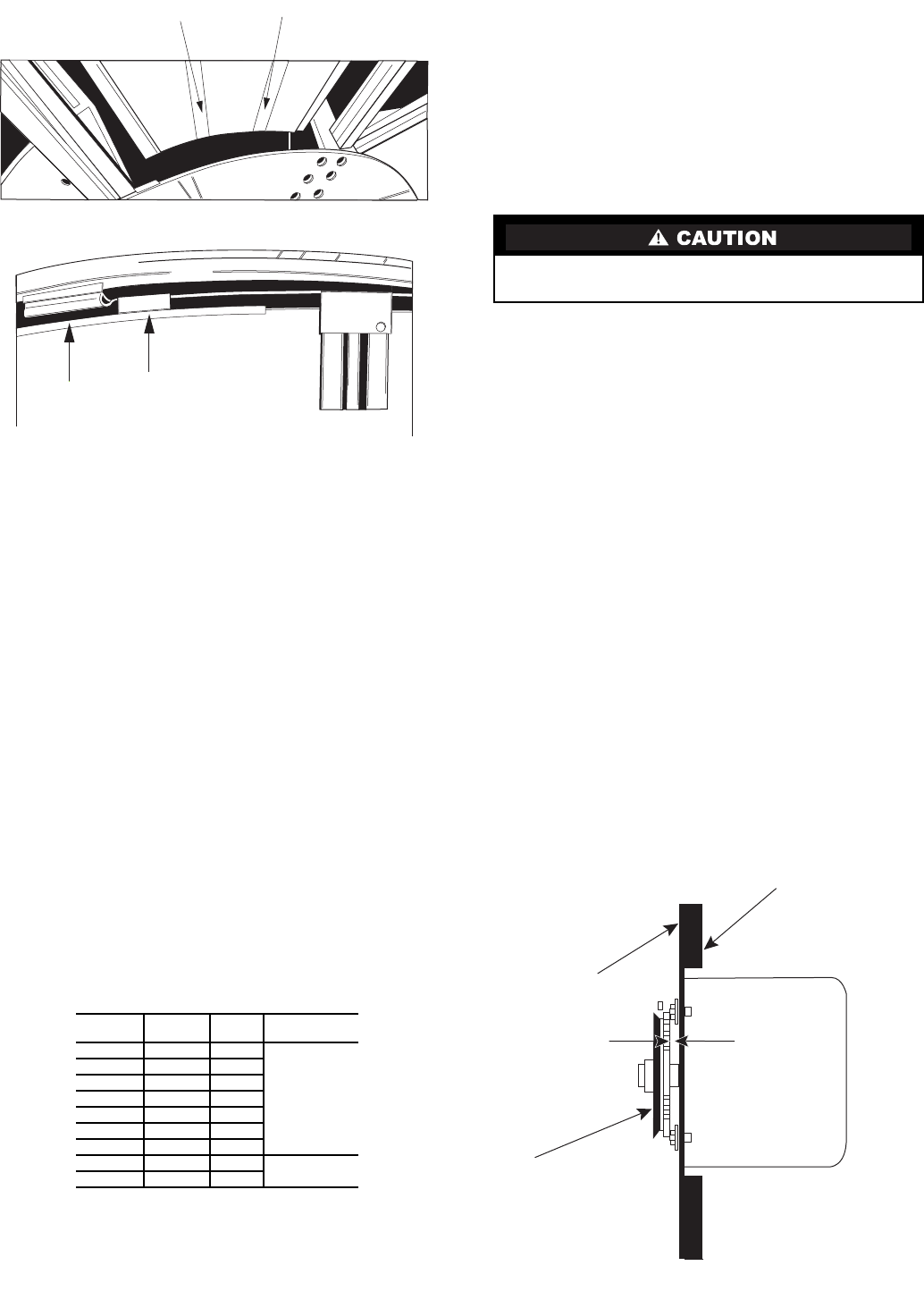
77
Wheel Drive Motor and Pulley Replacement
(62M170-095 Units)
1. Disconnect power to wheel drive motor.
2. Remove belt from pulley and position temporarily around
wheel rim.
3. Loosen setscrew in wheel drive pulley using Allen
wrench and remove pulley from motor drive shaft.
4. While supporting weight of drive motor in one hand,
loosen and remove 4 mounting bolts.
5. Install replacement motor with hardware kit supplied.
6. Install pulley to dimension shown in Fig. 90 and secure
setscrew to drive shaft.
7. Stretch belt over pulley and engage in groove.
Belt Replacement
1. Obtain access to the pulley side bearing access plate.
Remove two bearing access plate retaining screws and
the access plate.
2. Using hexagonal wrench, loosen setscrew in bearing
locking collar. Using light hammer and drift (in drift pin
hole) tap collar in the direction of wheel rotation to
unlock collar. Remove collar.
3. Using socket wrench with extension, remove two nuts
which secure bearing housing to the bearing support
beam. Slide bearing from shaft.
NOTE: Slight hand pressure against wheel rim will
lift weight of wheel from inner race of bearing to assist
bearing removal and installation. If not removable by
hand, use bearing puller.
4. Using a wrench, remove diameter seal retaining screws or
hub seal retaining screws. Remove diameter seals or hub
seal from bearing beam. See Fig. 91.
5. Form a small loop of belt and pass it through the hole in
the bearing support beam. Grasp the belt at the wheel hub
and pull the entire belt down. Loop the trailing end of the
belt over the shaft (Fig. 91 shows belt partially through
the opening).
6. Reinstall the bearing onto the wheel shaft, being careful
to engage the two locating pins into the holes in the
bearing support beam. Secure the bearing with two
self-locking nuts.
7. Install the belts around the wheel and pulley according to
the instructions provided with the belt.
8. Reinstall diameter seals or hub seal and tighten retaining
screws. Rotate wheel in clockwise direction to determine
that wheel rotates freely with slight drag on seals.
9. Reinstall bearing locking collar. Rotate collar by hand in
the direction the wheel rotates (see label provided on each
cassette for wheel rotation). Lock in position by tapping
drift pin hole with hammer and drift. Secure in position
by tightening setscrew.
10. Reinstall bearing access cover.
11. Apply power to wheel and ensure that the wheel rotates
freely without interference.
ALTERNATE BELT REPLACEMENT METHODS — Alter-
nate belt replacement methods may be used in some applica-
tions depending upon accessibility of the cassette. Consult
instructions provided with the belt for further information.
Protect hands and belt from possible sharp edges of hole in
bearing support beam.
Wheel
Drive
Motor
Insulation
Seal
Plate
Pulley
Dimension A
Fig. 90 — Pulley Location
62M
UNIT SIZE
ERV
WHEEL
WHEEL
SERIES
DIMENSION A
(in.)
170 ERC-3623 36
1/4
225 ERC-3623 36
285 ERC-3628 36
330 ERC-5245 52
430 ERC-5245 52
550 ERC-5262 52
640 ERC-5262 52
750 ERC-6488 64 7/16
950 ERC-6488 64
NOTE: The ERV wheel model number contains the wheel series number,
and is located on a label near the drive pulley. For example, ERC-5245D is
a 52 series wheel.
Imbedded Stiffeners
CATCH PULL TAB
Fig. 88 — Motor Side View of Segment
Fig. 89— Latch Segment Retaining Brackets
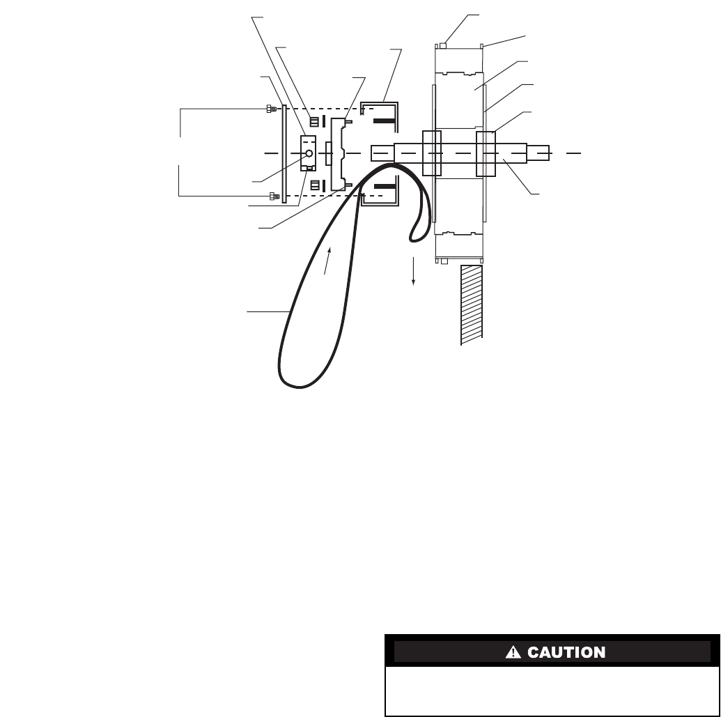
78
MAINTENANCE
Routine maintenance of the energy recovery cassettes
includes periodic cleaning of the energy recovery wheel as well
as inspection of the air seals and wheel drive components as
follows:
Cleaning — The need for periodic cleaning of the energy
recovery wheel will be a function of operating schedule, cli-
mate and contaminants in the indoor air being exhausted, and
the outdoor air being supplied to the building.
The air exchange wheel is “self-cleaning” with respect to
dry particles due to its laminar flow characteristics. Smaller
particles pass through; larger particles land on the surface and
are blown clear as the flow direction is reversed. Any material
that builds up on the face of the wheel can be removed with a
brush or vacuum. The primary need for cleaning is to remove
oil-based aerosols that have condensed on energy transfer
surfaces.
A characteristic of all dry desiccants, such films can close
off micron sized pores at the surface of the desiccant material,
reducing the efficiency by which the desiccant can adsorb and
desorb moisture and also build up so as to reduce airflow.
In a reasonably clean indoor environment such as a school
or office building, measurable reductions of airflow or loss of
sensible effectiveness may not occur for several years. Measur-
able changes in latent energy transfer can occur in shorter
periods of time in applications such as moderate occupant
smoking or cooking facilities. In applications experiencing
unusually high levels of occupant smoking or oil-based aero-
sols such as industrial applications involving the ventilation of
machine shop areas for example, annual washing of energy
transfer may be necessary to maintain latent transfer efficiency.
Proper cleaning of the energy recovery wheel will restore latent
effectiveness to near original performance.
To clean, gain access to the energy recovery wheel and
remove wheel. Brush foreign material from the face of the
wheel. Wash the wheel in a 5% solution of non-acid based coil
cleaner or alkaline detergent and warm water.
Soak in the solution until grease and tar deposits are
loosened.
NOTE: Some staining of the desiccant may remain and is not
harmful to performance.
Before removing, rapidly run finger across surface of wheel
to separate polymer strips for better cleaning action. Rinse
dirty solution from wheel and remove excess water before
reinstalling.
Air Seals — Diameter seals are provided on each cassette
to minimize transfer of air between the counter flowing
airstreams.
To adjust diameter seals, loosen diameter seal adjusting
screws and back seals away from wheel surface (Fig. 92).
Rotate wheel clockwise until two opposing spokes are hidden
behind the bearing support beam. Using a folded piece of paper
as a feeler gage, position paper between the wheel surface and
diameter seals. Adjust seals towards wheel surface until a slight
friction on the feeler gage (paper) is detected when gage is
moved along the length of the spoke. Retighten adjusting
screws and recheck clearance with “feeler” gage.
Do not use acid based cleaners, aromatic solvents, steam or
temperatures in excess of 170 F; damage to the wheel may
result.
Bearing
Access Plate
Locking
Collar
Locking
Nut (2)
Bearing
Housing
Bearing
Support
Beam
Belt (Shown in
Place)
Wheel Rim
Wheel
Hub (2)
Taper - Lock
Hub Collar (2)
Shaft
PULL
FEED
Pulley
Side Motor
Side
Belt
Locating Pin
Drift Hole
Set Screw
Retaining
Screws
Fig. 91 — Belt Replacement (Diameter Seals Removed)
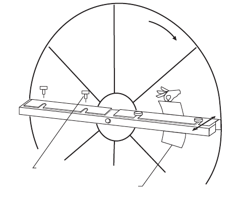
79
Wheel Drive Components — The wheel drive motor
bearings are pre-lubricated and no further lubrication is neces-
sary. Make certain air cooling ports are not blocked.
The wheel drive a pulley is secured to the drive motor shaft
by a setscrew. The setscrew is secured with removable adhe-
sive to prevent loosening. Annually confirm setscrew is secure.
The wheel drive belt is a urethane stretch belt designed to
provide constant tension through the life of the belt. No adjust-
ment is required. Inspect the drive belt annually for proper
tracking and tension. A properly tensioned belt will turn
the wheel immediately after power is applied with no visible
slippage during start-up.
Rotation
To
Adjust
Adjusting Screws
Feeler Gage
Fig. 92 — Diameter Seal Adjustment

Manufacturer reserves the right to discontinue, or change at any time, specifications or designs without notice and without incurring obligations.
Catalog No. 536-220 Printed in U.S.A. Form 62M-1SI Pg 80 1-06 Replaces: New
Copyright 2006 Carrier Corporation
Book 1 4
Tab 10a 12a
Manufacturer reserves the right to discontinue, or change at any time, specifications or designs without notice and without incurring obligations.
Catalog No. 536-220 Printed in U.S.A. Form 62M-1SI Pg CL-1 1-06 Replaces: New
Book 1 4
Ta b 1 a 1 2a
START-UP CHECKLIST
A. Project Information: Start-Up Performed By ____________________________
Name __________________________________________________
Job Name ______________________________________________
ERV Unit Designation ____________________________________
Phone Number __________________________________________
Design Information
Application Coupled to rooftop unit or stand-alone.
CFM
External Static Pressure
Supply Discharge Down or horizontal (use horizontal for mated application)
Return Discharge Down or horizontal (use horizontal for mated application)
Voltage/Phase
ERV Unit Part Number
Specify Rooftop Unit. NOTE: Complete This Section for Coupled Applications Only
Model Number
HVAC Unit Discharge Type Down discharge or horizontal discharge.
Roof Curb (Option) Yes No
14-in. Tall Roof Curb Field install
Vibration Isolation Curb Field install
Transition (Option) NOTE: Complete This Section for Coupled Applications Only.
Rooftop Unit Discharge Down or horizontal discharge rooftop unit.
Percent Outside Air Outside air thru ERV unit as a percent of total rooftop unit cfm.
Transition Part Number Field install
Inside Mounting Kit (Option) Yes No NOTE: Complete This Section for Indoor Applications Only.
Factory installed Removes rainhoods and adds duct flanges.
Electrical Disconnect (Option) Yes No
Fused Factory installed
Switched Factory installed
Two-Position Motorized Dampers (Option) Yes No
Outside Air Damper Factory installed
Exhaust Air Damper Factory installed
Economizer (Accessory for Rooftop Unit) Yes No NOTE: Do Not Use With Wheel Bypass Option.
Field install Special economizers required for some rooftop units. See the price pages.
Wheel Bypass With Stop Jog Control (Option) Yes No NOTE: Do Not Use With Economizer Option.
Factory installed Stops the ERV wheel rotation for free-cooling.
Stop Jog Control (Option) Yes No NOTE: Use With Economizer Option.
Factory installed Jogs the wheel during economizer mode to expel contaminants.
Pre-Heater (Option) Yes No
kWFactory installed
Temp Control
Temp and Static Pressure Control
Frost Protection (Option) Yes No NOTE: Do Not Use With Pre-Heater.
Factory installed Defrosts wheel with exhaust air, by shutting down OA blower.
Low Temperature Lock Out (Option) Yes No
Factory installed Shut down ERV unit at low temperature set point.
Filter Maintenance Indicator (Option) Yes No
Factory installed Senses static pressure across OA filters (can be set for return filters).
ERV Blower Maintenance Indicator (Option) Yes No
Factory installed Monitors OA and EA blowers and sends signal on electrical spike.
ERV Wheel Maintenance Indicator (Option) Yes No
Factory installed Monitors ERV wheel and sends signal on electrical spike.
Airflow Monitor (Option) Yes No
Factory installed Gages display static pressure across wheel for OA and exhaust air.
ERV Control Timer (Option) Yes No
24 Volt Mounted in ERV Factory installed 24 hour /7daytimermountedinERVunit.
115 Volt Remote Mount Field install 24 hour /7 day timer field mounted in remote location.
VAV Control (Option) Yes No
Factory installed Provides independent VFD control for both OA and exhaust air.
CO2Sensor (Option) Yes No
Wall Mount or Duct Mount Field install
Duct Mount With External View Field install
For 62M040 Cabinet Only Yes No
Equipment Support Field installed Use for coupled applications.
Base Rail Option Factory installed Must be ordered when 62M040 sits on a roof curb.
Hinged Door Option Factory installed Provides hinges and latches on both access doors.
2-in. Filters Option Factory installed Replaces the standard 1-in. filters with 2-in. high efficiency, pleated.
Door Interlock Safety Switches Factory installed Cuts power to ERV unit when access doors are opened during operation.
Test Port Option Factory installed Allows for convenient monitoring of static /airflow across ERV wheel.
