Carrier Air Compressor 09Rh Users Manual 5fh 2xa
09RH to the manual 912737ef-fa5a-4ba4-a99d-e08927179a58
2015-01-24
: Carrier Carrier-Air-Compressor-09Rh-Users-Manual-310370 carrier-air-compressor-09rh-users-manual-310370 carrier pdf
Open the PDF directly: View PDF ![]() .
.
Page Count: 40
Manufacturer reserves the right to discontinue, or change at any time, specifications or designs without notice and without incurring obligations.
New PC 802 Catalog No. 510-509 Printed in U.S.A. Form 5F,H/09RH-2XA Pg 1 8-02 Replaces: 5F,H/09RH-1XA
Book 2244
Tab 2a4a3a4b
Book 3
Ta b D E 1
Application Data
CONTENTS
Page
COMPRESSOR PHYSICAL DATA . . . . . . . . . . . . . . . . . 1
OPEN-DRIVE COMPRESSORS . . . . . . . . . . . . . . . . 2-29
Operating Requirements . . . . . . . . . . . . . . . . . . . . . . . . . 2
Discharge Temperature . . . . . . . . . . . . . . . . . . . . . . . . . . 2
High Compression Ratio . . . . . . . . . . . . . . . . . . . . . . . . . 2
Suction Gas Superheat. . . . . . . . . . . . . . . . . . . . . . . . . . . 2
Keeping Liquid Refrigerant Out of
Compressor. . . . . . . . . . . . . . . . . . . . . . . . . . . . . . . . . . . . 2
Compressor Capacity Notes . . . . . . . . . . . . . . . . . . . . . 4
Compressor Features and Accessories . . . . . . . . . . 4
Capacity Control . . . . . . . . . . . . . . . . . . . . . . . . . . . . . . . . 19
Hot Gas Bypass . . . . . . . . . . . . . . . . . . . . . . . . . . . . . . . . . 26
Motor Selection Data . . . . . . . . . . . . . . . . . . . . . . . . . . . . 27
Drive Packages. . . . . . . . . . . . . . . . . . . . . . . . . . . . . . . . . . 27
BOOSTER COMPRESSORS FOR REFRIG-
ERANT 12, 22, 502, AND 507/404A . . . . . . . . . 29-37
Booster Application Data. . . . . . . . . . . . . . . . . . . . . . . . 29
Rating Basis . . . . . . . . . . . . . . . . . . . . . . . . . . . . . . . . . . . . 29
“R” Factors . . . . . . . . . . . . . . . . . . . . . . . . . . . . . . . . . . . . . 29
Multistage System Pointers . . . . . . . . . . . . . . . . . . . . . 29
Safety Factors. . . . . . . . . . . . . . . . . . . . . . . . . . . . . . . . . . . 29
Page
Determining Intermediate Pressure . . . . . . . . . . . . . 31
Gas Desuperheating . . . . . . . . . . . . . . . . . . . . . . . . . . . . 31
Liquid Cooling . . . . . . . . . . . . . . . . . . . . . . . . . . . . . . . . . . 31
Oil Separators and Lubrication. . . . . . . . . . . . . . . . . . 31
Control Pressurestat for Booster
Application . . . . . . . . . . . . . . . . . . . . . . . . . . . . . . . . . . . 32
Discharge Valve Springs . . . . . . . . . . . . . . . . . . . . . . . . 33
Water-Cooled Heads . . . . . . . . . . . . . . . . . . . . . . . . . . . . 33
Motor Selection Data . . . . . . . . . . . . . . . . . . . . . . . . . . . . 33
Compressor Starting Torque . . . . . . . . . . . . . . . . . . . . 33
Selection Procedure . . . . . . . . . . . . . . . . . . . . . . . . . . . . 33
CONDENSERS . . . . . . . . . . . . . . . . . . . . . . . . . . . . . . . 37-40
Condenser Physical Data . . . . . . . . . . . . . . . . . . . . . . . 37
Condenser Selection Considerations . . . . . . . . . . . 37
Condenser Duty. . . . . . . . . . . . . . . . . . . . . . . . . . . . . . . . . 37
Pulldown . . . . . . . . . . . . . . . . . . . . . . . . . . . . . . . . . . . . . . . . 37
Fouling and Fouling Factors . . . . . . . . . . . . . . . . . . . . 37
Water Circuiting Arrangements . . . . . . . . . . . . . . . . . 39
Economics . . . . . . . . . . . . . . . . . . . . . . . . . . . . . . . . . . . . . . 39
Condenser Performance with
Ethylene Glycol . . . . . . . . . . . . . . . . . . . . . . . . . . . . . . . 39
COMPRESSOR PHYSICAL DATA (Table 1)
Table 1 — Open-Drive Compressors
LEGEND *40 F saturated suction, 105 F saturated discharge, 15 F superheat, 0° F
subcooling.
†Net oil pressure = oil pressure gage reading – suction pressure. The
above oil pressure is typical with mineral or alkylbenzene oils. A slight
increase in oil pressure may result with the use of PolyolEster (POE) oil.
COMPRESSOR MODEL 5F20 5F30 5F40 5F60 5H40 5H46 5H60 5H66 5H80 5H86 5H120 5H126
Nominal Horsepower R-12, R-134a 57
1/210 15 25 40 40 50 50 75 75 100
R-22 10 15 20 25 40 60 60 75 75 100 125 150
R-502, R-507/404A 10 15 20 25 40 60 60 75 75 100 125 150
Number of Cylinders 23464466881212
Bore (in.) 21/221/221/221/231/431/431/431/431/431/431/431/4
Stroke (in.) 22222
3/437/16 23/437/16 23/437/16 23/437/16
Displacement Cfm at 1750 Rpm 19.8 29.8 39.8 59.6 92.4 115.5 138.4 173.0 184.7 231.0 276.8 346.0
Ratings in Tons* R-12, R-134a 5.18 7.76 10.5 15.7 24.7 30.6 37.0 45.9 49.5 61.1 74.0 91.8
R-22 8.46 12.7 16.8 25.3 39.6 49.1 59.4 73.8 79.2 98.2 119.0 145.0
R-502 8.85 13.2 17.7 26.5 40.5 50.2 60.9 75.4 81.2 100.7 122.0 151.2
R-507/404A 8.40 12.56 16.77 25.17 38.48 47.72 57.73 71.58 76.98 95.47 115.47 143.19
Max Speed (rpm) 1750 1750 1750 1750 1750 1750 1750 1750 1750 1750 1750 1750
Min Speed (rpm) For Lubrication 400 400 400 400 400 400 400 400 400 400 400 400
For Unloader Action 600 700 800 900 800 800 900 900 1100 1100 900 900
Net Oil Pressure (psig)† 45 45 45 45 45 45 45 45 45 45 45 45
Oil Charge (pt) 55
1/212 13 18 18 21 21 41 41 61 61
Normal Oil Level in Sight Glass C.L. C.L.
3/8″
Above
C.L.
3/8″
Above
C.L.
C.L. C.L. C.L. C.L. C.L. C.L. C.L. C.L.
Min Oil Pressure for Unloader Action (psig) 22 28 35 35 35 35 35 35 35 35 35 35
Suction Line ODF (in.) 11/815/815/821/825/825/831/831/831/831/841/841/8
Discharge Line ODF (in.) 7/813/813/815/821/821/831/831/831/831/841/841/8
Bare Compressor Weight (lb) 175 215 355 400 610 610 795 795 1115 1115 1580 1580
C.L. — Center Line
ODF — Outside Diameter Female (in.)
5F,H
Open-Drive Compressors
09RH
Water-Cooled Condensers
2
OPEN-DRIVE COMPRESSORS
These compressors are designed to operate with Refriger-
ants 12, 22, 134a, 502, or 507/404A. See Table 1.
Operating Requirements — Satisfactory operation of
a reciprocating compressor depends on 3 fundamental
requirements:
1. Prevention of excess discharge temperature.
2. Adequate compressor lubrication.
3. A clean and dry system.
Discharge Temperature — The temperature at the
discharge valves within the cylinders is a controlling factor.
Some cooling of the discharge gas occurs before reaching the
discharge stop valve, thus when water-cooled heads are used,
this cooling is greater than it is without water cooling. To pre-
vent excessive temperature at the compressor discharge valves,
the following temperatures, when measured immediately
following the discharge stop valve, must never be exceeded:
For nonwater-cooled heads . . . . . . . . . . . . . . . . . . 275 F max
For water-cooled heads . . . . . . . . . . . . . . . . . . . . . 250 F max
The approximate discharge gas temperature can be found
by using the following equation:
Where:
T2= Discharge temperature, F absolute
T1= Suction temperature, F absolute (including
superheat)
P2= Discharge pressure, psia
P1= Suction pressure, psia
N = Compression exponent of the gas (see Table 2)
Table 2 — Compression Exponent “N”
*For R-134a and R-507/404A refer to the Carlyle Compressor Selection
program (http://www.carlylecompressor.com/TechnicalInfo/Carwin.htm) to
determine discharge temperature. The selection program can also be
used for R-22 and R-502 in place of the discharge temperature formulas.
The value of compression exponent “N” depends upon the
properties of gas compressed, degree of cooling in compressor
jacket, leakages, etc.
To simplify discharge temperature calculations, the preced-
ing formula may be stated in the following form:
T2 = [(460 + T1) x C] – 460
Where:
T2 = Discharge temperature, F actual
T1 = Suction gas temperature, F actual (including
superheat)
Values for “C” at various compression ratios are listed in
Table 3.
Table 3 — “C” Factors
*For R-134a and R-507/404A refer to the Carlyle Compressor Selection
program (http://www.carlylecompressor.com/TechnicalInfo/Carwin.htm) to
determine discharge temperature. The selection program can also be
used for R-22 and R-502 in place of the discharge temperature formulas.
Example:
Refrigerant 12
Factor C = 1.33
Suction Temperature, T1 = 0° F saturated, superheated
to 65 F
Solution:
T2 = [(460 + 65) x 1.33] – 460
= 698 – 460
= 238 F
Although exponents are shown for high compression ratios,
these are for information only. Rating tables define allowable
selection and operation limits.
High Compression Ratio — Avoid compressor oper-
ation at compressor ratios exceeding those covered in the rating
tables. For operating conditions outside the limits shown in
these tables, use 2-stage compression. Care must be taken to
prevent the compressor from pulling down to levels outside the
rating tables.
Suction Gas Superheat — Excessive suction gas super-
heat will result in abnormally high discharge temperatures,
which must be avoided. When using Refrigerants 12, 134a, 502,
and 507/404A it is recommended that the actual suction gas
temperature not exceed the values in Table 4.
Table 4 — Actual Suction Gas Temperature
Limits (F) Refrigerants 12, 134a, 502, and
507/404A*
*With Refrigerant 22, the suction gas superheat should never exceed
25 F for continuous operation.
Keeping Liquid Refrigerant Out of Compres-
sor — Liquid refrigerant, or excessive amounts of entrained
liquid particles in suction gas must be kept out of the compres-
sor by proper system design and compressor control. Under
operating conditions, presence of unevaporated liquid refriger-
ant in the compressor tends to break down oil film on cylinder
walls, resulting in increased wear and loss of machine capacity.
During compressor operation, proper adjustment of the
expansion valve will prevent excessive amounts of liquid from
entering the compressor.
N – 1
T2 = T1(P2 )N
P1
COMPRESSION
RATIO WITHOUT
WATER-COOLED
HEADS*
WITH
WATER-COOLED
HEADS
R-22
=Discharge
Suction psia R-12 R-22 R-502
21.216 1.325 1.234 1.240
31.191 1.258 1.216 1.218
41.177 1.240 1.206 1.205
51.172 1.234 1.197 1.199
61.166 1.232 1.190 1.196
81.160 1.228 1.178 1.192
10 1.155 1.225 1.169 1.187
12 1.150 1.224 1.161 1.182
N – 1
C = (P2 )N
P1
COMPRESSION
RATIO WITHOUT
WATER-COOLED
HEADS*
WITH
WATER-COOLED
HEADS
R-22
=Discharge psia
Suction psia R-12 R-22 R-502
21.14 1.17 1.13 1.15
31.19 1.25 1.22 1.22
41.23 1.31 1.27 1.27
51.26 1.36 1.30 1.31
61.29 1.40 1.33 1.34
81.33 1.47 1.37 1.40
10 1.36 1.53 1.40 1.44
12 1.38 1.57 1.41 1.47
Compression Ratio P2= 8
P1
SATURATED SUCTION
GAS TEMP –60 –50 –40 –30 –20 –10 0 AND
ABOVE
Actual
Suction
Gas Temp
R-12 — — 35 45 55 65 65
R-134a —————— 65
R-502
R-507/404A 25 35 45 55 65 65 65
3
During compressor shutdown, gravity, thermal action and
refrigerant absorption can result in a refrigerant and oil mixture
in compressor crankcase. Gravity flow can be prevented by the
use of recommended loops, but thermal action and the absorp-
tion of refrigerant by lubricating oil cannot be prevented by
piping design.
For the above reasons, the compressor must be controlled
during idle times by one of the following methods.
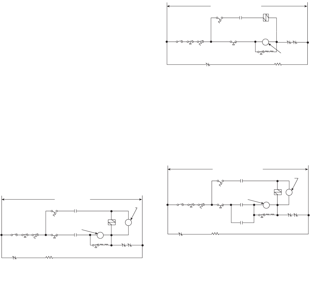
MINIMUM PROTECTION — The minimum protection that
Carrier will allow is shown in Fig. 1. Actuated control thermo-
stat energizes crankcase heater and closes the liquid line
solenoid valve simultaneously. With crankcase heaters
energized, the crankcase temperature is always held above
shutdown temperature in the evaporator coil and there will be
no refrigerant migration to the crankcase.
With this type of control, a control relay is required and
crankcase heaters have to be energized when the compressor is
not operating.
The control relay coil is located in parallel with the liquid
line solenoid, and a normally open control relay contact is
added in series with the compressor starter and other auxiliary
safety devices.
When the thermostat calls for cooling, the solenoid valve
opens and control relay is energized. This closes the relay
contact and, if other safety devices are in their normal position,
compressor will start. Simultaneously, the normally closed
compressor auxiliary contact will open, removing crankcase
heaters from the circuit.
When the thermostat is satisfied, the solenoid will close and
control relay is deenergized. This opens relay contacts and
compressor stops. This causes compressor auxiliary contacts to
close, energizing crankcase heaters.
Specifications are sometimes written to call for a degree of
protection greater than that afforded by the standard method. If
this is the case, either single pumpout or automatic pumpdown
control may be required.
AUTOMATIC PUMPDOWN CONTROL (Fig. 2) — Pump-
down control is the most effective means of compressor control
in keeping liquid refrigerant out of the crankcase on system
shutdown.
In the basic pumpdown control sequence, the thermostat
controls the liquid line solenoid valve to stop or start the flow
of refrigerant to the evaporator as required.
The pumpdown control system permits compressor cycling
if a system malfunction allows low side pressure to rise.
Although this cycling is sometimes considered objectionable, it
illustrates need for maintenance attention and provides positive
protection against liquid refrigerant accumulating in the
compressor crankcase.
Do not use pumpdown control with dry expansion coolers
as it may cause frost pinching or freeze-up. Do not use
pumpdown control with dry expansion coolers if it is antici-
pated that there will be short bursts of system operation, as this
will result in a gradual loss of oil.
SINGLE PUMPOUT CONTROL (Fig. 3) — Pumpout con-
trol is not as effective as pumpdown control in keeping liquid
refrigerant out of the crankcase. However, it is usually satisfac-
tory when used with crankcase heaters if pumpdown is not
acceptable.
Single pumpout control is similar to pumpdown control,
except that a pumpout relay is added, a normally open com-
pressor auxiliary contact is necessary, and energizing of crank-
case heaters is required at end of each operating cycle.
With single pumpout control, when the thermostat is satis-
fied, the compressor pumps down once and stops. It starts
again only when the thermostat calls for cooling. In pumpdown
control, the compressor cycles only on the low-pressure switch,
regardless of thermostat demands.
Do not use pumpout control with dry expansion coolers as it
may cause frost pinching or freeze-up.
MANUAL PUMPDOWN — The compressor may be con-
trolled manually without the use of pumpdown, or single
pumpout control, and without crankcase heaters, provided the
system is at all times under control of a qualified operator. The
operator will pump down the system by use of manual valves
and will keep liquid, suction and discharge valves closed when
the machine is not operating.
HIGH-
PRESS.
SWITCH
AUTO-
OFF
SWITCH
OIL
FAILURE
SWITCH
LOW-
PRESS.
SWITCH
CONTROL
RELAY
COMPR
STARTER
THERMO
EVAP
AUX CONT
SOLENOID
VALVE
OIL FAILURE
SWITCH
OVERLOADS
CONTROL
RELAY
CONTROL POWER
COMPR
AUX CONT
CRANKCASE
HEATERS
Fig. 1 — Minimum Protection
HIGH-
PRESS.
SWITCH
AUTO-
OFF
SWITCH
OIL
FAILURE
SWITCH
LOW-
PRESS.
SWITCH COMPR
STARTER
THERMO
EVAP
AUX
CONT
SOLENOID
VALVE
OIL FAILURE
SWITCH
OVERLOADS
CONTROL POWER CIRCUIT
COMPR
AUX CONT
CRANKCASE
HEATERS
Fig. 2 — Automatic Pumpdown Control
HIGH-
PRESS.
SWITCH
AUTO-
OFF
SWITCH
OIL
FAILURE
SWITCH
LOW-
PRESS.
SWITCH
COMPR
STARTER
THERMO
EVAP
AUX CONT
SOLENOID
VALVE
OIL FAILURE
SWITCH
OVERLOADS
CONTROL POWER CIRCUIT
COMPR
AUX CONT
CRANKCASE
HEATERS
PUMPOUT
RELAY CONTACT
COMP
AUX
CONTACT
PUMPOUT
RELAY
COIL
Fig. 3 — Single Pumpout Control
4
Compressor Capacity Notes
1. Compressor capacities are based on 1750 rpm and 15 F
subcooling for all unit sizes and refrigerants.
2. Multiplying factors for other rpm:
See Multiplying Factors chart on page 31.
3. Liquid subcooling greater than (less than) 15 F incorpo-
rated in ratings increases (decreases) system capacity by
1/2 of 1% for each degree of subcooling. When correcting
for subcooling, brake horsepower does not change.
4. Refrigerant temperatures shown in Table 5 are saturation
temperatures corresponding to pressures indicated at
compressor. Actual gas temperatures are higher because
of superheat.
5. Capacities are based on actual suction gas tempera-
tures to compressor of 65 F for R-12, R-134a, R-502,
and R-507/404A. (This assumes superheat is obtained
from liquid suction interchanger or in evaporator.)
Capacity corrections, other than for rated suction gas
temperatures, may be obtained by using Rating Basis and
Capacity Multipliers Tables 6 and 7. Refrigerant-22
suction gas superheat for ratings (15 F) normally occurs
because of expansion valve operation and line losses.
Therefore, R-22 ratings can be used without adjustment.
An alternate method for capacity correction is to run the
Carlyle Selection program to obtain performance ratings
at other than 65 F return gas temperature.
Compressor ratings and capacities are included in
Tables 8-12.
Compressor Features and Accessories
WATER-COOLED HEADS AND OIL COOLERS — Water
cooled heads are typically not necessary for R-12 or R-134a
applications within the range of compressor ratings shown in
this publication. For R-502, or R-507/404A at the shaded con-
ditions shown in the compressor ratings tables, water-cooled
heads may be necessary, if the discharge temperature is greater
than 275 F. The discharge temperature will increase with return
gas temperature.
When operating conditions are such that suction gas
becomes highly superheated and/or the compression ratio is
high, it is recommended that an oil cooler be used on the com-
pressor. An oil cooler is required on increased displacement
compressors (5H46, 66, 86, and 126) on installations where
compressor(s) can be subjected to extended periods of continu-
ous, fully unloaded operation. These periods do not afford
sufficient removal of compression and friction heat, and could
result in overheating of the running gear, shaft seal and crank-
case oil. The addition of an oil cooler removes excessive
heat, ensuring increased life expectancy of compressor and
components.
Extended periods of continuous, fully unloaded operation
will occur usually on variable-volume installations that use hot
gas bypass to maintain conditions under all load situations.
Without hot gas bypass, the compressor will usually cycle on
the low-pressure switch (or temperature controlling device)
giving time for seal, oil and crankcase to cool.
On multiple-compressor installations where all units are
manifolded into one refrigerant circuit, the controls should be
designed to cycle off compressors at light loads to put maxi-
mum output on the still operative compressor. It is always
desirable for the compressor to operate with as many cylinders
as possible in loaded condition.
Water-cooled oil cooler package is available from the
factory and is easily field installed on all 5 Series compressors.
Refer to 5F,H Compressor Ratings to determine when oil
coolers are required. These ratings, however, do not indicate oil
cooler requirements during periods of extended continuous
operation under fully unloaded operation. This should be
determined on individual job basis.
Water flow through compressor heads (and water-cooled oil
coolers, if used) must be shut off when the compressor is not
running to prevent refrigerant vapors from condensing at the
compressor during OFF cycles. For this purpose a solenoid
valve is recommended in the water supply line to compressor
heads.
Values listed in Table 13 assume a water temperature rise of
30 degrees. Oil cooler and water-cooled heads must be piped in
series, with the oil cooler first. Leaving water temperature
should be between 100 F and 120 F, with 120 F being maxi-
mum allowable temperature. Maximum working pressure for
water-cooled heads is 125 psi.
Table 5 — Total Heat Rejection Factors
Total Heat Rejection (tons) = Compressor Capacity (tons) x Heat Rejection Factor*
*Complete capacity corrections before calculating for total heat rejection (refer to Compressor Capacity Note 5).
RPM 1450 1160
Capacity 0.835 0.674
Bhp 0.798 0.602
SAT.
DISCHARGE
TEMP (F)
SATURATED SUCTION TEMPERATURES (F)
–60–50–40–30–20–100 102030323435363840424445464850
80 1.610 1.547 1.490 1.439 1.391 1.344 1.300 1.256 1.214 1.176 1.168 1.160 1.155 1.150 1.142 1.138 1.129 1.121 1.118 1.112 1.110 1.105
90 —1.590 1.526 1.472 1.422 1.373 1.327 1.282 1.238 1.196 1.190 1.180 1.178 1.171 1.165 1.157 1.150 1.142 1.138 1.135 1.129 1.122
100 —1.630 1.570 1.513 1.461 1.409 1.361 1.312 1.267 1.222 1.215 1.205 1.202 1.200 1.190 1.180 1.175 1.165 1.162 1.158 1.150 1.143
105 —1.655 1.595 1.538 1.483 1.431 1.380 1.330 1.283 1.237 1.232 1.220 1.219 1.215 1.205 1.194 1.189 1.178 1.175 1.170 1.162 1.155
110 ——1.622 1.564 1.508 1.454 1.402 1.350 1.301 1.253 1.248 1.238 1.235 1.228 1.220 1.208 1.200 1.192 1.190 1.185 1.178 1.168
120 ——1.698 1.628 1.565 1.508 1.451 1.395 1.341 1.288 1.280 1.270 1.265 1.261 1.251 1.240 1.232 1.222 1.220 1.215 1.205 1.195
130 —————1.567 1.506 1.445 1.383 1.327 1.320 1.310 1.300 1.295 1.285 1.275 1.268 1.255 1.250 1.248 1.238 1.225
140 ——————1.565 1.500 1.430 1.368 1.355 1.345 1.338 1.332 1.318 1.310 1.300 1.290 1.288 1.280 1.270 1.255
145 ———————1.526 1.455 1.390 1.378 1.365 1.355 1.350 1.340 1.330 1.320 1.310 1.300 1.298 1.285 1.270

5
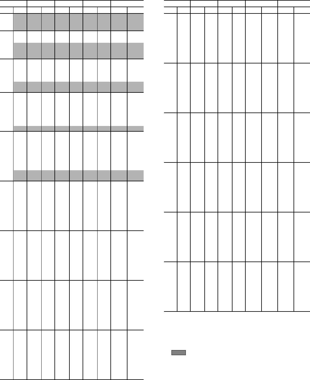
Table 6 — Rating Basis and Capacity Multipliers for R-12 and R-134a*
LEGEND
*R-134a capacity multipliers start at 0° F SST and above.
SST
(F)
SDT
(F)
RETURN GAS TEMPERATURE (F)
–30 –20 –10 0 10 20 30 40 50 60 65
–30
90 0.963 0.966 0.970 0.973 0.977 0.981 0.985 0.989 0.993 0.998 1.000
100 0.951 0.956 0.960 0.965 0.970 0.976 0.981 0.986 0.992 0.997 1.000
110 0.938 0.944 0.950 0.957 0.963 0.970 0.977 0.983 0.990 0.997 1.000
120 0.923 0.931 0.939 0.947 0.955 0.964 0.972 0.980 0.988 0.996 1.000
130 0.906 0.916 0.926 0.936 0.945 0.958 0.966 0.976 0.986 0.995 1.000
140 0.887 0.899 0.912 0.924 0.936 0.949 0.960 0.972 0.983 0.994 1.000
150 0.865 0.880 0.895 0.910 0.924 0.939 0.953 0.967 0.980 0.993 1.000
–20
90 —0.968 0.971 0.974 0.978 0.982 0.985 0.989 0.994 0.998 1.000
100 —0.957 0.962 0.967 0.971 0.976 0.981 0.987 0.992 0.997 1.000
110 —0.946 0.952 0.953 0.964 0.971 0.977 0.984 0.990 0.997 1.000
120 —0.932 0.940 0.948 0.956 0.964 0.972 0.980 0.988 0.996 1.000
130 —0.917 0.927 0.937 0.947 0.957 0.967 0.976 0.986 0.995 1.000
140 —0.900 0.912 0.925 0.937 0.949 0.960 0.972 0.983 0.994 1.000
150 —0.880 0.895 0.910 0.925 0.939 0.953 0.967 0.980 0.993 1.000
–10
90 ——0.973 0.976 0.979 0.983 0.986 0.990 0.994 0.998 1.000
100 ——0.964 0.968 0.973 0.977 0.982 0.987 0.992 0.997 1.000
110 ——0.953 9.959 0.965 0.971 0.978 0.984 0.990 0.997 1.000
120 ——0.940 0.949 0.957 0.965 0.973 0.981 0.988 0.996 1.000
130 ——0.928 0.938 0.948 0.957 0.967 0.977 0.986 0.995 1.000
140 ——0.913 0.925 0.937 0.949 0.961 0.972 0.983 0.994 1.000
150 ——0.896 0.910 0.925 0.939 0.953 0.967 0.980 0.993 1.000
0
90 ———0.978 0.981 0.984 0.987 0.991 0.994 0.998 1.000
100 ———0.970 0.974 0.979 0.983 0.988 0.993 0.998 1.000
110 ———0.961 0.967 0.973 0.979 0.985 0.991 0.997 1.000
120 ———0.951 0.958 0.965 0.973 0.981 0.989 0.996 1.000
130 ———0.939 0.949 0.958 0.968 0.977 0.986 0.995 1.000
140 ———0.926 0.938 0.950 0.961 0.972 0.983 0.995 1.000
150 ———0.911 0.925 0.939 0.953 0.967 0.980 0.994 1.000
10
90 ————0.983 0.984 0.989 0.992 0.995 0.998 1.000
100 ————0.976 0.980 0.984 0.989 0.993 0.998 1.000
110 ————0.969 0.974 0.980 0.985 0.991 0.997 1.000
120 ————0.960 0.967 0.974 0.982 0.989 0.996 1.000
130 ————0.950 0.959 0.968 0.977 0.987 0.996 1.000
140 ————0.939 0.950 0.962 0.973 0.984 0.995 1.000
150 ————0.926 0.940 0.954 0.967 0.981 0.994 1.000
20
90 —————0.988 0.990 0.993 0.995 0.998 1.000
100 —————0.982 0.986 0.990 0.994 0.998 1.000
110 —————0.976 0.981 0.986 0.992 0.997 1.000
120 —————0.969 0.975 0.982 0.989 0.996 1.000
130 —————0.961 0.969 0.978 0.987 0.996 1.000
140 —————0.951 0.962 0.973 0.984 0.995 1.000
150 —————0.941 0.954 0.968 0.981 0.994 1.000
30
90 ——————0.992 0.994 0.996 0.999 1.000
100 ——————0.988 0.991 0.994 0.998 1.000
110 ——————0.983 0.987 0.992 0.997 1.000
120 ——————0.977 0.983 0.990 0.997 1.000
130 ——————0.971 0.979 0.987 0.996 1.000
140 ——————0.963 0.974 0.984 0.995 1.000
150 ——————0.955 0.968 0.981 0.994 1.000
40
90 ———————0.996 0.997 0.999 1.000
100 ———————0.992 0.995 0.998 1.000
110 ———————0.989 0.993 0.998 1.000
120 ———————0.985 0.991 0.997 1.000
130 ———————0.980 0.988 0.996 1.000
140 ———————0.975 0.985 0.995 1.000
150 ———————0.969 0.981 0.994 1.000
50
90 ————————0.998 0.999 1.000
100 ————————0.996 0.999 1.000
110 ————————0.994 0.998 1.000
120 ————————0.992 0.997 1.000
130 ————————0.989 0.996 1.000
140 ————————0.986 0.995 1.000
150 ————————0.982 0.994 1.000
SDT — Saturated Discharge Temperature
SST — Saturated Suction Temperature

6
Table 7 — Rating Basis and Capacity Multipliers for R-502 and R-507/404A
LEGEND
SST
(F)
SDT
(F)
RETURN GAS TEMPERATURE (F)
–30 –20 –10 0 10 20 30 40 50 60 65
–30
90 0.913 0.922 0.931 0.941 0.950 0.959 0.968 0.977 0.986 0.995 1.000
100 0.893 0.905 0.916 0.928 0.939 0.956 0.962 0.973 0.984 0.995 1.000
110 0.870 0.884 0.899 0.913 0.927 0.941 0.954 0.967 0.981 0.994 1.000
120 0.843 0.861 0.879 0.896 0.913 0.929 0.945 0.961 0.977 0.992 1.000
130 0.812 0.834 0.855 0.876 0.896 0.916 0.935 0.954 0.973 0.991 1.000
140 0.774 0.801 0.826 0.852 0.876 0.900 0.923 0.946 0.968 0.989 1.000
150 0.728 0.760 0.792 0.822 0.851 0.880 0.908 0.935 0.961 0.987 1.000
–20
90 —0.925 0.933 0.942 0.951 0.960 0.969 0.978 0.987 0.996 1.000
100 —0.906 0.918 0.929 0.940 0.951 0.962 0.973 0.984 0.995 1.000
110 —0.886 0.900 0.914 0.928 0.941 0.955 0.968 0.981 0.994 1.000
120 —0.862 0.879 0.896 0.913 0.930 0.946 0.962 0.977 0.992 1.000
130 —0.833 0.855 0.876 0.896 0.916 0.935 0.954 0.973 0.991 1.000
140 —0.800 0.826 0.851 0.876 0.899 0.923 0.945 0.968 0.989 1.000
150 —0.758 0.796 0.821 0.850 0.879 0.907 0.935 0.961 0.987 1.000
–10
90 ——0.936 0.944 0.953 0.961 0.970 0.978 0.987 0.996 1.000
100 ——0.920 0.931 0.942 0.952 0.963 0.974 0.984 0.995 1.000
110 ——0.901 0.915 0.927 0.942 0.955 0.968 0.981 0.994 1.000
120 ——0.880 0.897 0.914 0.930 0.946 0.962 0.977 0.992 1.000
130 ——0.855 0.876 0.896 0.916 0.935 0.954 0.973 0.991 1.000
140 ——0.825 0.850 0.875 0.899 0.923 0.945 0.968 0.989 1.000
150 ——0.788 0.819 0.849 0.878 0.907 0.934 0.961 0.987 1.000
0
90 ———0.947 0.955 0.963 0.971 0.979 0.988 0.996 1.000
100 ———0.933 0.943 0.954 0.964 0.974 0.985 0.995 1.000
110 ———0.917 0.930 0.943 0.956 0.969 0.981 0.994 1.000
120 ———0.898 0.915 0.931 0.947 0.962 0.978 0.993 1.000
130 ———0.876 0.896 0.916 0.936 0.955 0.973 0.991 1.000
140 ———0.850 0.875 0.899 0.922 0.945 0.968 0.989 1.000
150 ———0.817 0.848 0.877 0.906 0.934 0.961 0.987 1.000
10
90 ————0.958 0.965 0.973 0.980 0.988 0.996 1.000
100 ————0.946 0.956 0.965 0.975 0.985 0.995 1.000
110 ————0.932 0.945 0.957 0.970 0.982 0.994 1.000
120 ————0.916 0.932 0.947 0.963 0.978 0.993 1.000
130 ————0.897 0.917 0.936 0.955 0.973 0.991 1.000
140 ————0.874 0.898 0.922 0.945 0.968 0.989 1.000
150 ————0.846 0.876 0.905 0.933 0.961 0.987 1.000
20
90 —————0.968 0.975 0.982 0.988 0.996 1.000
100 —————0.958 0.967 0.977 0.986 0.995 1.000
110 —————0.947 0.959 0.971 0.982 0.994 1.000
120 —————0.933 0.948 0.963 0.978 0.993 1.000
130 —————0.917 0.936 0.955 0.973 0.991 1.000
140 —————0.898 0.922 0.945 0.968 0.989 1.000
150 —————0.875 0.904 0.933 0.960 0.987 1.000
30
90 ——————0.978 0.984 0.990 0.997 1.000
100 ——————0.970 0.978 0.987 0.996 1.000
110 ——————0.961 0.972 0.983 0.994 1.000
120 ——————0.950 0.964 0.979 0.993 1.000
130 ——————0.937 0.956 0.974 0.991 1.000
140 ——————0.922 0.945 0.968 0.989 1.000
150 ——————0.903 0.932 0.960 0.987 1.000
40
90 ———————0.986 0.991 0.997 1.000
100 ———————0.980 0.988 0.996 1.000
110 ———————0.974 0.984 0.995 1.000
120 ———————0.966 0.980 0.993 1.000
130 ———————0.956 0.974 0.991 1.000
140 ———————0.945 0.968 0.989 1.000
150 ———————0.931 0.959 0.987 1.000
50
90 ————————0.994 0.998 1.000
100 ————————0.990 0.997 1.000
110 ————————0.985 0.995 1.000
120 ————————0.981 0.994 1.000
130 ————————0.975 0.992 1.000
140 ————————0.968 0.989 1.000
150 ————————0.959 0.987 1.000
SDT — Saturated Discharge Temperature
SST — Saturated Suction Temperature

7
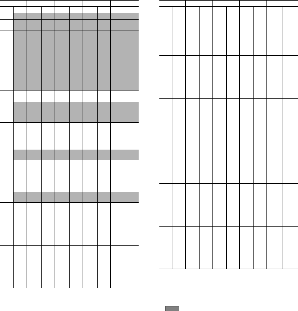
Table 8 — Compressor Ratings; R-12
LEGEND
NOTES:
1. Shaded ratings require an oil cooler when using a liquid-
suction interchanger, or when 50 degrees of superheat is
exceeded.
2. Refer to Table 5 for Total Heat Rejection.
UNIT5F205F305F405F60
SST SDT Cap. Bhp Cap. Bhp Cap. Bhp Cap. Bhp
–40
80 0.6 1.7 1.0 2.7 1.3 3.4 2.0 5.3
90 0.5 1.6 0.8 2.6 1.1 3.3 1.6 5.1
100 0.4 1.5 0.6 2.4 0.9 3.1 1.3 4.7
–30
80 1.0 2.2 1.5 3.4 2.0 4.2 3.0 6.6
90 0.8 2.2 1.3 3.3 1.8 4.3 2.6 6.6
100 0.7 2.1 1.1 3.2 1.5 4.2 2.2 6.4
105 0.6 2.1 1.0 3.2 1.4 4.2 2.0 6.3
110 0.6 2.0 0.9 3.1 1.3 4.1 1.9 6.1
–20
80 1.4 2.6 2.2 4.0 2.9 5.1 4.3 8.0
90 1.3 2.7 1.9 4.1 2.6 5.2 3.8 8.1
100 1.1 2.7 1.7 4.1 2.3 5.3 3.4 8.1
105 1.0 2.7 1.6 4.1 2.1 5.3 3.1 8.1
110 0.9 2.7 1.5 4.0 2.0 5.3 2.9 8.0
120 0.8 2.6 1.2 3.9 1.7 5.2 2.5 7.8
–10
80 2.0 3.1 3.0 4.6 3.9 5.9 5.9 9.2
90 1.8 3.2 2.7 4.8 3.6 6.2 5.4 9.5
100 1.6 3.3 2.4 4.9 3.2 6.4 4.8 9.8
105 1.5 3.3 2.3 5.0 3.0 6.5 4.5 9.8
110 1.4 3.3 2.1 5.0 2.8 6.5 4.3 9.9
120 1.2 3.3 1.9 5.0 2.5 6.6 3.7 9.8
130 1.0 3.2 1.6 4.9 2.2 6.6 3.2 9.7
0
80 2.6 3.4 4.0 5.2 5.2 6.6 7.9 10.3
90 2.4 3.6 3.6 5.5 4.8 7.0 7.2 10.9
100 2.2 3.8 3.3 5.7 4.4 7.4 6.6 11.3
105 2.1 3.9 3.1 5.8 4.1 7.6 6.2 11.5
110 1.9 3.9 3.0 5.9 3.9 7.7 5.9 11.7
120 1.7 4.0 2.6 6.0 3.5 7.9 5.3 11.9
130 1.5 4.0 2.3 6.0 3.1 8.1 4.7 12.0
140 1.3 4.0 2.0 6.0 2.7 8.1 4.1 11.9
145 1.2 4.0 1.9 5.9 2.5 8.1 3.8 11.8
10
80 3.4 3.7 5.1 5.6 6.8 7.1 10.3 11.1
90 3.1 4.0 4.8 6.1 6.3 7.8 9.5 12.0
100 2.9 4.3 4.4 6.4 5.8 8.3 8.7 12.8
105 2.7 4.4 4.2 6.6 5.5 8.6 8.3 13.1
110 2.6 4.5 4.0 6.8 5.3 8.8 7.9 13.4
120 2.4 4.7 3.6 7.0 4.8 9.2 7.1 13.9
130 2.1 4.8 3.2 7.2 4.3 9.5 6.4 14.2
140 1.9 4.9 2.8 7.3 3.8 9.7 5.7 14.4
145 1.7 4.9 2.7 7.3 3.6 9.8 5.3 14.4
20
80 4.3 3.9 6.6 5.9 8.7 7.5 13.1 11.6
90 4.0 4.3 6.1 6.5 8.1 8.3 12.1 12.8
100 3.7 4.7 5.6 7.0 7.5 9.1 11.2 13.9
105 3.6 4.8 5.4 7.3 7.2 9.4 10.8 14.4
110 3.4 5.0 5.2 7.5 6.9 9.8 10.3 14.9
120 3.1 5.3 4.7 7.9 6.3 10.4 9.4 15.7
130 2.8 5.5 4.3 8.2 5.7 10.9 8.5 16.4
140 2.5 5.7 3.8 8.5 5.1 11.3 7.7 16.8
145 2.4 5.8 3.6 8.6 4.8 11.5 7.2 17.0
30
80 5.5 4.0 8.2 6.0 10.9 7.7 16.4 11.7
90 5.1 4.5 7.7 6.8 10.2 8.7 15.3 13.3
100 4.7 5.0 7.1 7.5 9.5 9.7 14.2 14.8
105 4.5 5.2 6.9 7.8 9.1 10.1 13.7 15.5
110 4.4 5.4 6.6 8.1 8.7 10.6 13.1 16.1
120 4.0 5.8 6.1 8.7 8.0 11.4 12.1 17.3
130 3.7 6.2 5.5 9.2 7.3 12.1 11.1 18.3
140 3.3 6.4 5.0 9.6 6.7 12.8 10.0 19.1
145 3.1 6.6 4.8 9.8 6.3 13.0 9.5 19.5
40
80 6.7 3.9 10.1 5.9 13.5 7.7 20.3 11.4
90 6.3 4.5 9.5 6.9 12.7 8.9 19.0 13.4
100 5.9 5.1 8.9 7.7 11.8 10.1 17.7 15.2
105 5.7 5.4 8.6 8.2 11.4 10.6 17.1 16.1
110 5.5 5.7 8.3 8.6 11.0 11.2 16.5 16.9
120 5.1 6.2 7.6 9.3 10.1 12.2 15.3 18.5
130 4.7 6.7 7.0 10.0 9.3 13.2 14.0 19.9
140 4.2 7.1 6.4 10.6 8.5 14.0 12.8 21.1
145 4.0 7.3 6.1 10.9 8.1 14.4 12.2 21.7
UNIT5F205F305F405F60
SST SDT Cap. Bhp Cap. Bhp Cap. Bhp Cap. Bhp
42
80 7.0 3.8 10.5 5.9 14.1 7.6 21.1 11.2
90 6.6 4.5 9.9 6.8 13.2 8.9 19.8 13.3
100 6.2 5.2 9.3 7.8 12.3 10.1 18.5 15.3
105 5.9 5.5 8.9 8.2 11.9 10.7 17.9 16.2
110 5.7 5.8 8.6 8.6 11.5 11.3 17.2 17.1
120 5.3 6.3 8.0 9.4 10.6 12.4 15.9 18.7
130 4.9 6.8 7.4 10.2 9.8 13.4 14.7 20.2
140 4.5 7.2 6.8 10.8 8.9 14.3 13.4 21.5
145 4.2 7.4 6.4 11.1 8.5 14.7 12.8 22.1
44
80 7.3 3.8 11.0 5.8 14.7 7.5 22.0 11.0
90 6.9 4.5 10.3 6.8 13.8 8.9 20.6 13.2
100 6.4 5.2 9.6 7.8 12.9 10.1 19.3 15.3
105 6.2 5.5 9.3 8.2 12.4 10.8 18.6 16.2
110 6.0 5.8 9.0 8.7 12.0 11.4 18.0 17.2
120 5.5 6.4 8.3 9.5 11.1 12.5 16.7 18.9
130 5.1 6.9 7.7 10.3 10.2 13.5 15.4 20.4
140 4.7 7.4 7.1 11.0 9.4 14.5 14.1 21.8
145 4.5 7.6 6.8 11.3 8.9 15.0 13.5 22.5
45
80 7.5 3.8 11.2 5.8 15.0 7.5 22.4 10.9
90 7.0 4.5 10.5 6.8 14.0 8.9 21.1 13.2
100 6.6 5.2 9.9 7.8 13.1 10.2 19.7 15.3
105 6.3 5.5 9.5 8.3 12.7 10.8 19.0 16.3
110 6.1 5.8 9.2 8.7 12.2 11.4 18.4 17.2
120 5.7 6.4 8.5 9.6 11.3 12.5 17.0 19.0
130 5.2 6.9 7.9 10.4 10.4 13.6 15.7 20.6
140 4.8 7.4 7.2 11.1 9.6 14.6 14.4 22.0
145 4.6 7.6 6.9 11.4 9.2 15.1 13.8 22.6
46
80 7.6 3.7 11.4 5.7 15.3 7.5 22.9 10.8
90 7.2 4.5 10.7 6.8 14.3 8.8 21.5 13.1
100 6.7 5.2 10.1 7.8 13.4 10.2 20.9 15.3
105 6.5 5.5 9.7 8.3 12.9 10.8 19.4 16.3
110 6.2 5.8 9.4 8.7 12.5 11.4 18.8 17.2
120 5.8 6.4 8.7 9.6 11.6 12.6 17.4 19.0
130 5.3 7.0 8.1 10.4 10.7 13.7 16.1 20.7
140 4.9 7.5 7.4 11.1 9.8 14.7 14.7 22.2
145 4.7 7.7 7.1 11.5 9.4 15.2 14.1 22.8
48
80 7.9 3.7 11.9 5.6 15.9 7.4 23.8 10.6
90 7.5 4.4 11.2 6.8 14.9 8.8 22.4 13.0
100 7.0 5.2 10.5 7.8 14.0 10.2 21.0 15.2
105 6.7 5.5 10.1 8.3 13.5 10.8 20.3 16.3
110 6.5 5.8 9.8 8.8 13.0 11.5 19.6 17.3
120 6.0 6.5 9.1 9.7 12.1 12.7 18.2 19.2
130 5.6 7.1 8.4 10.5 11.2 13.9 16.8 20.9
140 5.1 7.6 7.7 11.3 10.3 14.9 15.4 22.5
145 4.9 7.8 7.4 11.7 9.8 15.4 14.7 23.2
50
80 8.2 3.6 12.3 5.6 16.5 7.3 24.8 10.4
90 7.8 4.4 11.6 6.6 15.5 8.8 23.3 12.8
100 7.3 5.2 10.9 7.8 14.5 10.2 21.8 15.2
105 7.0 5.5 10.5 8.3 14.1 10.9 21.1 16.3
110 6.8 5.9 10.2 8.8 13.6 11.5 20.4 17.3
120 6.3 6.5 9.5 9.8 12.6 12.8 18.9 19.3
130 5.8 7.1 8.8 10.7 11.7 14.0 17.5 21.1
140 5.3 7.7 8.1 11.5 10.7 15.1 16.1 22.8
145 5.1 7.9 7.7 11.8 10.3 15.7 15.4 23.5
Bhp — Brake Horsepower
Cap. — Capacity (Tons)
SDT — Saturated Discharge Temperature (F)
SST — Saturated Suction Temperature (F)
8
Table 8 — Compressor Ratings; R-12 (cont)
LEGEND
NOTES:
1. Shaded ratings require an oil cooler when using a liquid-
suction interchanger, or when 50 degrees of superheat is
exceeded.
2. An oil cooler is recommended for all long stroke compressors
(5H46,66,86 and 126).
3. Refer to Table 5 for Total Heat Rejection.
UNIT 5H40 5H46 5H60 5H66
SST SDT Cap. Bhp Cap. Bhp Cap. Bhp Cap. Bhp
–40
80 3.2 9.1 4.0 11.9 4.9 13.1 6.1 17.1
90 2.7 8.8 3.4 11.5 4.1 12.7 5.2 16.6
100 2.2 8.4 2.8 11.0 3.4 12.1 4.3 15.8
–30
80 4.9 11.1 6.0 14.4 7.3 16.0 9.1 20.8
90 4.3 11.0 5.3 14.3 6.4 15.9 8.0 20.7
100 3.7 10.7 4.6 13.9 5.6 15.5 6.9 20.3
105 3.4 10.5 4.2 13.7 5.1 15.3 6.4 19.9
110 3.1 10.3 3.9 13.4 4.7 15.0 5.9 19.5
–20
80 6.9 13.0 8.6 16.9 10.4 18.9 13.0 24.6
90 6.2 13.1 7.7 17.1 9.4 19.2 11.6 24.9
100 5.5 13.1 6.8 17.1 8.3 19.2 10.3 24.9
105 5.1 13.0 6.4 17.0 7.8 19.1 9.7 24.8
110 4.8 12.9 6.0 16.8 7.3 18.9 9.0 24.7
120 4.1 12.6 5.1 16.4 6.3 18.4 7.8 24.1
–10
80 9.5 14.9 11.7 19.3 14.2 21.7 17.7 28.3
90 8.6 15.3 10.7 19.9 12.9 22.4 16.1 29.1
100 7.8 15.5 9.6 20.2 11.7 22.8 14.5 29.7
105 7.3 15.6 9.1 20.3 11.0 22.9 13.7 29.8
110 6.9 15.6 8.6 20.3 10.4 23.0 13.0 29.9
120 6.1 15.5 7.6 20.2 9.2 22.9 11.5 29.8
130 5.3 15.3 6.6 19.9 8.0 22.5 10.0 29.4
0
80 12.6 16.6 15.5 21.6 18.8 24.3 23.4 31.6
90 11.6 17.3 14.3 22.5 17.3 25.5 21.5 33.1
100 10.5 17.9 13.0 23.3 15.8 26.4 19.6 34.3
105 10.0 18.1 12.4 23.6 15.1 26.7 18.7 34.8
110 9.5 18.3 11.8 23.8 14.3 27.0 17.8 35.1
120 8.5 18.5 10.6 24.1 12.9 27.4 16.0 35.6
130 7.6 18.6 9.4 24.1 11.4 27.5 14.2 35.8
140 6.6 18.4 8.3 24.0 10.0 27.3 12.5 35.6
145 6.2 18.3 7.7 23.8 9.4 27.1 11.7 35.3
10
80 16.3 18.0 20.1 23.5 24.4 26.5 30.2 34.5
90 15.1 19.2 18.6 24.9 22.6 28.2 28.0 36.7
100 13.9 20.1 17.1 26.2 20.8 29.7 25.8 38.6
105 13.3 20.5 16.4 26.7 19.9 30.3 24.7 39.4
110 12.7 20.9 15.7 27.2 19.0 30.9 23.6 40.2
120 11.5 21.5 14.2 27.9 17.3 31.8 21.4 41.4
130 10.4 21.9 12.8 28.4 15.6 32.4 19.3 42.4
140 9.2 22.0 11.4 28.7 13.9 32.7 17.3 42.6
145 8.7 22.1 10.8 28.7 13.1 32.8 16.3 42.7
20
80 20.7 19.1 25.5 24.9 30.9 28.1 38.3 36.6
90 19.3 20.7 23.7 26.9 28.8 30.5 35.7 39.7
100 17.9 22.1 22.0 28.7 26.7 32.7 33.1 42.5
105 17.2 22.7 21.1 29.5 25.6 33.6 31.8 43.7
110 16.5 23.3 20.3 30.3 24.6 34.5 30.5 44.8
120 15.1 24.3 18.6 31.6 22.6 36.0 28.0 46.8
130 13.7 25.1 16.9 32.6 20.5 37.2 25.5 48.4
140 12.4 25.6 15.3 33.3 18.6 38.1 23.1 49.6
145 11.7 25.8 14.5 33.6 17.6 38.4 21.9 50.1
30
80 25.9 19.7 31.8 25.7 38.6 29.1 47.9 37.8
90 24.2 21.8 29.8 28.4 36.1 32.2 44.8 41.9
100 22.6 23.7 27.8 30.8 33.7 35.0 41.8 45.6
105 21.7 24.6 26.8 31.9 32.4 36.4 40.3 47.3
110 20.9 25.4 25.8 33.0 31.2 37.6 38.8 48.9
120 19.3 26.8 23.8 34.9 28.8 39.8 35.8 51.8
130 17.7 28.1 21.8 36.5 26.5 41.7 32.8 54.3
140 16.1 29.1 19.9 37.8 24.1 43.3 29.9 56.3
145 15.3 29.5 18.9 38.3 23.0 44.0 28.5 57.2
40
80 31.9 19.7 39.2 25.6 47.5 29.0 58.9 37.8
90 30.0 22.4 36.9 29.1 44.6 33.0 55.4 43.0
100 28.0 24.8 34.5 32.2 41.8 36.7 51.9 47.7
105 27.1 25.9 33.3 33.7 40.4 38.4 50.1 50.0
110 26.1 27.0 32.2 25.1 39.0 40.1 48.4 52.1
120 24.2 29.0 29.9 37.7 36.2 43.1 44.9 56.0
130 22.4 30.8 27.6 40.0 33.4 45.8 41.5 59.5
140 20.5 32.3 25.3 42.0 30.7 48.1 38.1 62.6
145 19.6 33.0 24.2 42.8 29.3 49.1 36.4 63.9
UNIT 5H40 5H46 5H60 5H66
SST SDT Cap. Bhp Cap. Bhp Cap. Bhp Cap. Bhp
42
80 33.2 19.6 40.8 25.5 49.4 28.9 61.3 37.6
90 31.2 22.4 38.4 29.1 46.5 33.1 57.7 43.0
100 29.2 24.9 36.0 32.4 43.6 36.9 54.1 48.0
105 28.3 26.1 34.8 34.0 42.1 38.7 52.3 50.4
110 27.3 27.3 33.6 35.5 40.7 40.5 50.5 52.6
120 25.3 29.4 31.2 38.2 37.8 43.6 46.9 56.8
130 23.4 31.2 28.8 40.6 34.9 46.5 43.4 60.5
140 21.5 32.9 26.5 42.7 32.1 49.0 39.8 63.7
145 20.5 33.6 25.3 43.7 30.7 50.1 38.1 65.2
44
80 34.6 19.5 42.5 25.3 51.4 28.7 63.8 37.4
90 32.5 22.4 40.0 29.1 49.4 33.1 60.1 43.0
100 30.5 25.1 37.5 32.6 45.4 37.1 56.4 48.3
105 29.5 26.3 36.3 34.2 43.9 39.0 54.5 50.7
110 28.5 27.5 35.0 35.8 42.4 40.8 52.7 53.1
120 26.4 29.7 32.6 38.7 39.5 44.2 49.0 57.5
130 24.4 31.7 30.1 41.2 36.5 47.2 45.3 61.4
140 22.5 33.5 27.7 43.5 33.6 49.9 41.7 64.9
145 21.5 34.2 26.5 44.5 32.1 51.1 39.9 66.4
45
80 35.3 19.4 43.3 25.2 52.4 28.6 65.1 37.2
90 33.2 22.4 40.8 29.1 49.4 33.1 61.3 43.0
100 31.1 25.1 38.3 32.6 46.3 37.2 57.5 48.4
105 30.1 26.4 37.0 34.3 44.8 39.1 55.6 50.9
110 29.1 27.6 35.8 35.9 43.3 41.0 53.8 53.3
120 27.0 29.9 33.3 38.9 40.3 44.4 50.0 57.8
130 25.0 31.9 30.8 41.5 37.3 47.5 46.3 61.9
140 23.0 33.7 28.3 43.9 34.3 50.3 42.6 65.4
145 22.0 34.6 27.1 44.9 32.9 51.5 40.8 67.1
46
80 36.0 19.3 44.2 25.1 53.5 28.5 66.4 37.1
90 33.9 22.4 41.6 29.1 50.4 33.0 62.5 43.0
100 31.8 25.2 39.1 32.7 47.3 37.3 58.7 38.5
105 30.7 26.5 37.8 34.4 45.8 39.2 56.8 51.1
110 29.7 27.7 36.5 36.1 44.2 41.1 54.9 53.5
120 27.6 30.1 34.0 39.1 41.2 44.7 51.1 58.1
130 25.5 32.2 31.5 41.8 38.1 47.9 47.3 62.3
140 23.5 34.0 29.0 44.2 35.1 50.7 43.6 66.0
145 22.5 34.9 27.7 45.3 33.6 52.0 41.7 67.6
48
80 37.4 19.1 46.0 24.8 55.6 28.2 69.0 36.7
90 35.2 22.3 43.3 29.0 52.4 32.9 65.1 42.9
100 33.1 25.2 40.7 32.8 49.2 37.4 61.1 48.6
105 32.0 26.6 39.4 34.6 47.7 39.4 59.1 51.3
110 30.9 27.9 38.0 36.3 46.1 41.4 57.2 53.9
120 28.8 30.4 35.4 39.5 42.9 45.2 53.3 58.8
130 26.7 32.6 32.8 42.4 39.8 48.5 49.4 63.1
140 24.6 34.6 30.3 44.9 36.7 51.5 45.5 67.1
145 23.5 35.5 29.0 46.1 35.2 52.9 43.6 68.8
50
80 38.9 18.9 47.8 24.5 57.8 27.9 71.7 36.3
90 36.6 22.2 45.0 28.8 54.5 32.8 67.7 42.7
100 34.4 25.3 42.3 32.8 51.2 37.4 63.6 48.7
105 33.3 26.7 41.0 34.7 49.6 39.6 61.6 51.5
110 32.2 28.1 39.6 36.5 48.0 41.7 59.5 54.2
120 30.0 30.7 36.9 39.9 44.7 45.6 55.5 59.3
130 27.8 33.0 34.3 42.9 41.5 49.1 51.5 63.9
140 25.7 35.1 31.6 45.6 38.3 52.3 47.6 68.1
145 24.6 36.1 30.3 46.9 36.7 53.8 45.6 70.0
Bhp — Brake Horsepower
Cap. — Capacity (Tons)
SDT — Saturated Discharge Temperature (F)
SST — Saturated Suction Temperature (F)
9
Table 8 — Compressor Ratings; R-12 (cont)
LEGEND
NOTES:
1. Shaded ratings require an oil cooler when using a liquid-
suction interchanger, or when 50 degrees of superheat is
exceeded.
2. An oil cooler is recommended for all long stroke compressors
(5H46,66,86 and 126).
3. Refer to Table 5 for Total Heat Rejection.
UNIT 5H80 5H86 5H120 5H126
SST SDT Cap. Bhp Cap. Bhp Cap. Bhp Cap. Bhp
–40
80 6.6 17.5 8.2 22.8 9.8 25.8 12.2 33.4
90 5.6 17.0 7.0 22.1 8.3 24.9 10.3 32.4
100 4.6 16.2 5.8 21.1 6.9 23.7 8.6 30.8
–30
80 9.8 21.3 12.2 27.7 14.7 31.5 18.3 40.9
90 8.8 21.1 10.8 27.5 12.9 31.3 16.0 40.6
100 7.5 20.7 9.3 27.0 11.2 30.6 13.9 39.7
105 6.9 20.4 8.6 26.5 10.3 30.1 12.8 39.1
110 6.4 20.0 8.0 26.0 9.5 29.5 11.8 38.3
–20
80 13.9 25.2 17.3 32.7 20.9 37.3 25.9 48.4
90 12.5 25.4 15.5 33.1 18.7 37.8 23.3 49.0
100 11.1 25.4 13.8 33.1 16.6 37.7 20.6 49.0
105 10.4 25.3 13.0 33.0 15.6 37.6 19.3 48.8
110 9.7 25.2 12.1 32.8 14.6 37.3 18.1 48.5
120 8.4 24.6 10.5 32.0 12.6 36.3 15.6 47.3
–10
80 19.0 28.9 23.6 37.6 28.5 43.0 35.4 55.7
90 17.3 29.7 21.5 38.7 25.9 44.2 32.2 57.2
100 15.6 30.3 19.4 39.4 23.4 45.0 29.0 58.5
105 14.8 30.4 18.4 39.6 22.1 45.2 27.5 58.8
110 13.9 30.5 17.3 39.7 20.9 45.3 25.9 58.9
120 12.3 30.4 15.4 39.6 18.5 45.1 22.9 58.7
130 10.8 30.0 13.4 39.0 16.1 44.4 20.0 57.9
0
80 25.1 32.3 31.2 42.0 37.7 48.1 46.8 62.4
90 23.1 33.8 28.7 44.0 34.6 50.4 43.0 65.4
100 21.1 35.0 26.2 45.5 31.6 52.1 39.2 67.7
105 20.1 35.5 25.0 46.1 30.1 52.8 37.4 68.6
110 19.1 35.8 23.7 46.6 28.7 53.4 35.6 69.4
120 17.2 26.3 21.4 47.3 25.7 54.1 31.9 70.3
130 15.3 36.5 19.0 47.5 22.9 54.3 28.4 70.6
140 13.5 36.2 16.8 47.2 20.1 53.9 25.0 70.2
145 12.6 36.0 15.7 46.9 18.8 53.5 23.3 69.7
10
80 32.5 35.3 40.3 45.8 48.8 52.5 60.5 68.1
90 30.1 37.5 37.3 48.8 45.1 55.9 56.0 72.5
100 27.7 39.4 34.4 51.3 41.6 58.8 51.6 76.3
105 26.5 40.3 32.9 52.4 39.8 60.0 49.4 78.0
110 25.3 41.0 31.5 53.3 38.0 61.1 47.2 79.4
120 23.0 42.2 28.6 54.9 34.6 62.9 42.9 81.8
130 20.8 43.0 25.8 55.9 31.2 64.1 38.7 83.4
140 18.6 43.4 23.1 56.5 27.9 64.7 34.6 84.2
145 17.5 43.5 21.8 56.6 26.2 64.8 32.6 84.4
20
80 41.2 37.5 51.1 48.7 61.8 55.8 76.7 72.3
90 38.4 40.6 47.6 52.8 57.6 60.5 71.5 78.5
100 35.6 43.4 44.2 56.4 53.4 64.7 66.3 84.0
105 34.2 44.6 42.4 58.0 51.3 66.6 63.7 86.4
110 32.8 45.8 40.7 59.5 49.3 68.3 61.1 88.7
120 30.1 47.8 37.4 62.1 45.2 71.3 56.0 92.7
130 27.4 49.4 34.0 64.2 41.1 73.7 51.0 95.8
140 24.8 50.5 30.8 65.8 37.2 75.5 46.1 98.2
145 23.5 51.0 29.2 66.3 35.2 76.1 43.7 99.0
30
80 51.4 38.7 63.8 50.3 77.2 57.5 95.8 74.7
90 48.1 42.8 59.7 55.7 72.3 63.8 89.7 82.8
100 44.9 46.6 55.7 60.6 67.4 69.5 83.6 90.2
105 43.2 48.3 53.7 62.9 64.9 72.1 80.6 93.6
110 41.6 50.0 51.7 65.0 62.5 74.6 77.6 96.8
120 38.4 52.9 47.7 68.8 57.7 79.0 71.6 102.6
130 35.3 55.4 43.8 72.0 53.0 82.7 65.7 107.5
140 32.2 57.4 40.0 74.7 48.3 85.8 59.9 111.6
145 30.6 58.3 38.0 75.8 46.0 87.1 57.0 113.3
40
80 63.3 38.6 78.5 50.3 95.1 57.4 117.9 74.7
90 59.5 43.9 73.8 57.2 89.4 65.4 110.9 85.0
100 55.7 48.8 69.1 63.5 83.7 72.8 103.8 94.5
105 53.8 51.1 66.8 66.5 80.8 76.2 100.3 99.0
110 52.0 53.3 64.5 69.3 78.0 79.5 96.8 103.2
120 48.2 57.2 59.9 74.5 72.4 85.5 89.9 111.0
130 44.5 60.8 55.3 79.0 66.9 90.8 83.0 118.0
140 40.9 63.8 50.8 83.0 61.4 95.4 76.2 124.0
145 39.1 65.2 48.5 84.8 58.7 97.5 72.8 126.7
UNIT 5H80 5H86 5H120 5H126
SST SDT Cap. Bhp Cap. Bhp Cap. Bhp Cap. Bhp
42
80 65.9 38.5 81.8 50.0 99.0 57.1 122.8 74.3
90 62.0 44.0 76.9 57.3 93.1 65.5 115.5 85.1
100 58.1 49.1 72.1 63.9 87.2 73.2 108.2 95.1
105 56.2 51.5 69.7 67.0 84.3 76.8 104.6 99.8
110 54.2 53.8 67.3 70.0 81.4 80.3 101.0 104.2
120 50.4 58.0 62.5 75.4 75.6 86.6 93.9 112.5
130 46.6 61.8 57.8 80.3 69.9 92.3 86.8 119.9
140 42.8 65.0 53.1 84.6 64.3 97.2 79.7 126.4
145 40.9 66.5 50.8 86.5 61.4 99.4 76.2 129.2
44
80 68.6 38.2 85.1 49.7 103.0 56.7 127.8 73.9
90 64.6 44.0 80.1 57.3 96.9 65.5 120.3 85.2
100 60.6 49.4 75.1 64.2 90.9 73.6 112.8 95.6
105 58.0 51.9 72.6 67.5 87.9 77.4 109.1 100.5
110 56.6 54.3 70.2 70.6 84.9 81.0 105.4 105.2
120 52.6 58.7 65.3 76.4 79.0 87.7 98.0 113.9
130 48.7 62.7 60.4 81.6 73.1 93.7 90.7 121.7
140 44.8 66.2 55.6 86.1 67.2 99.0 83.4 128.6
145 42.8 67.8 53.2 88.2 64.3 101.3 79.8 131.7
45
80 70.0 38.1 86.8 49.5 105.0 56.5 130.3 73.6
90 65.9 44.0 81.7 57.2 98.9 65.5 122.7 85.1
100 61.8 49.5 76.7 64.4 92.8 73.7 115.1 95.8
105 59.8 52.1 74.2 67.7 89.7 77.6 111.3 100.8
110 57.8 54.5 71.7 70.9 86.7 81.3 107.6 105.6
120 53.7 59.1 66.7 76.8 80.7 88.2 100.1 114.6
130 49.7 63.2 61.7 82.2 74.7 94.4 92.7 122.6
140 45.8 66.8 56.8 86.9 68.7 99.8 85.3 129.7
145 43.8 68.4 54.4 89.0 65.8 102.3 81.6 132.9
46
80 71.4 37.9 88.5 49.3 107.1 56.3 132.9 73.3
90 67.2 44.0 83.4 57.2 100.9 65.4 125.2 85.1
100 63.1 49.6 78.2 64.5 94.7 73.9 117.5 96.0
105 61.0 52.2 75.7 67.9 91.6 77.8 113.7 101.1
110 59.0 54.7 73.2 71.2 88.5 81.6 109.8 106.0
120 54.9 59.4 68.1 77.3 82.4 88.7 102.2 115.2
130 50.8 63.6 63.1 82.7 76.3 95.1 94.7 123.5
140 46.8 67.3 58.1 87.6 70.3 100.7 87.2 130.8
145 44.8 69.0 55.7 89.8 67.3 103.2 83.5 134.1
48
80 74.2 37.5 92.0 48.8 111.4 55.7 138.1 72.6
90 69.9 43.8 86.7 57.0 105.0 65.2 130.2 84.8
100 65.7 49.7 81.5 64.7 98.6 74.1 122.3 96.3
105 63.5 52.5 78.8 68.3 95.4 78.2 118.4 101.6
110 61.4 55.1 76.2 71.7 92.2 82.2 114.4 106.8
120 57.2 60.0 71.0 78.1 85.9 89.6 106.6 116.4
130 53.1 64.5 65.8 83.9 79.7 96.4 98.8 125.2
140 48.9 68.4 60.7 89.0 73.4 102.3 91.1 133.0
145 46.9 70.2 58.2 91.4 70.4 105.0 87.3 136.5
50
80 77.1 37.0 95.6 48.2 115.7 55.0 143.6 71.7
90 72.7 43.6 90.2 56.8 109.1 64.9 135.4 84.5
100 68.3 49.8 84.8 64.8 102.6 74.2 127.3 96.4
105 66.2 52.7 82.1 68.5 99.3 78.5 123.2 102.0
110 64.0 55.4 79.4 72.1 96.1 82.7 119.2 107.4
120 59.6 60.6 74.0 78.8 89.6 90.5 111.1 117.6
130 55.3 65.3 68.7 84.9 83.1 97.6 103.1 126.8
140 51.1 69.5 63.4 90.4 76.7 103.9 95.2 135.0
145 49.0 71.4 60.8 92.9 73.5 106.8 91.2 138.8
Bhp — Brake Horsepower
Cap. — Capacity (Tons)
SDT — Saturated Discharge Temperature (F)
SST — Saturated Suction Temperature (F)
10
Table 9 — Compressor Ratings; R-22
LEGEND
NOTES:
1. Shaded ratings require an oil cooler and water-cooled
heads.
2. Refer to Table 5 for Total Heat Rejection.
UNIT5F205F305F405F60
SST SDT Cap. Bhp Cap. Bhp Cap. Bhp Cap. Bhp
–40 80 1.0 2.6 1.5 4.0 2.1 5.3 3.0 7.9
–30 80 1.5 3.4 2.3 5.1 3.1 6.7 4.6 10.0
90 1.3 3.3 2.0 5.0 2.7 6.7 4.1 10.0
–20
80 2.2 4.1 3.3 6.1 4.4 8.0 6.6 12.1
90 1.9 4.2 3.0 6.2 4.0 8.3 6.0 12.4
100 1.7 4.2 2.6 6.3 3.5 8.4 5.3 12.4
105 1.6 4.2 2.5 6.2 3.3 8.4 4.9 12.4
110 1.5 4.1 2.3 6.2 3.1 8.4 4.6 12.3
–10
80 3.0 4.7 4.6 7.1 6.1 9.3 9.2 14.1
90 2.7 4.9 4.2 7.4 5.5 9.8 8.3 14.7
100 2.5 5.1 3.8 7.6 5.0 10.1 7.5 15.1
105 2.3 5.1 3.5 7.6 4.7 10.3 7.1 15.2
110 2.2 5.1 3.3 7.7 4.5 10.4 6.7 15.3
120 1.9 5.1 2.9 7.7 4.0 10.5 5.9 15.2
0
80 4.0 5.3 6.1 7.9 8.1 10.4 12.2 15.8
90 3.7 5.6 5.6 8.4 7.5 11.1 11.2 16.8
100 3.4 5.9 5.1 8.8 6.8 11.7 10.2 17.6
105 3.2 6.0 4.9 9.0 6.5 12.0 9.7 17.9
110 3.0 6.1 4.6 9.1 6.2 12.2 9.3 18.1
120 2.7 6.3 4.2 9.3 5.5 12.6 8.3 18.5
10
80 5.3 5.8 8.0 8.6 10.6 11.3 15.9 17.1
90 4.9 6.2 7.4 9.3 9.8 12.3 14.7 18.6
100 4.5 6.7 6.8 10.0 9.0 13.2 13.6 19.8
105 4.3 6.9 6.5 10.2 8.6 13.6 13.0 20.3
110 4.1 7.0 6.2 10.5 8.3 13.9 12.4 20.8
120 3.7 7.3 5.7 10.9 7.5 14.6 11.3 21.6
130 3.3 7.5 5.1 11.2 6.8 15.1 10.1 22.2
20
80 6.8 6.0 10.2 9.1 13.6 11.9 20.4 17.9
90 6.3 6.7 9.5 10.0 12.6 13.2 19.0 19.9
100 5.8 7.3 8.8 10.9 11.7 14.4 17.6 21.6
105 5.6 7.6 8.5 11.3 11.2 14.9 16.9 22.4
110 5.4 7.8 8.1 11.6 10.8 15.5 16.2 23.2
120 4.9 8.3 7.4 12.3 9.9 16.4 14.8 24.5
130 4.5 8.7 6.8 12.8 9.0 17.3 13.5 25.6
135 4.2 8.8 6.4 13.1 8.5 17.6 12.8 26.0
30
80 8.5 6.1 12.8 9.2 17.1 12.1 25.6 18.1
90 8.0 7.0 12.0 10.5 16.0 13.8 24.0 20.6
100 7.4 7.8 11.2 11.6 14.9 15.3 22.3 23.0
105 7.1 8.1 10.8 12.1 14.3 16.0 21.5 24.1
110 6.9 8.5 10.4 12.6 13.8 16.7 20.7 25.1
120 6.3 9.1 9.6 13.5 12.7 18.0 19.1 26.9
130 5.8 9.7 8.8 14.3 11.6 19.2 17.5 28.6
135 5.5 9.9 8.4 14.7 11.1 19.7 16.7 29.3
40
80 10.6 6.0 15.9 9.1 21.2 12.0 3.18 17.4
90 9.9 7.0 14.9 10.6 19.9 14.0 29.9 20.6
100 9.3 8.0 14.0 12.0 18.6 15.9 28.0 23.6
105 9.0 8.5 13.5 12.7 18.0 16.8 27.0 25.0
110 8.7 8.9 13.0 13.3 17.3 17.7 26.1 26.4
120 8.0 9.8 12.1 14.5 16.1 19.3 24.2 28.9
130 7.4 10.5 11.2 15.6 14.8 20.9 22.3 31.1
135 7.1 10.9 10.7 16.1 14.2 21.6 21.3 32.1
UNIT5F205F305F405F60
SST SDT Cap. Bhp Cap. Bhp Cap. Bhp Cap. Bhp
42
80 11.0 5.9 16.5 9.0 22.1 11.9 33.2 17.2
90 10.4 7.0 15.6 10.5 20.8 14.0 31.2 20.5
100 9.7 8.0 14.6 12.0 19.4 15.9 29.2 23.7
105 9.4 8.5 14.1 12.7 18.8 16.9 28.2 25.1
110 9.0 9.0 13.6 13.4 18.1 17.8 27.2 26.5
120 8.4 9.9 12.7 14.7 16.8 19.5 25.3 29.2
130 7.7 10.7 11.7 15.8 15.5 21.2 23.3 31.5
135 7.4 11.0 11.2 16.4 14.9 21.9 22.4 32.6
44
80 11.5 5.9 17.2 8.9 23.1 11.8 34.6 16.9
90 10.8 7.0 16.2 10.5 21.7 14.0 32.5 20.4
100 10.1 8.1 15.2 12.0 20.3 16.0 30.5 23.7
105 9.8 8.6 14.7 12.8 19.6 17.0 29.5 25.2
110 9.5 9.0 14.2 13.5 18.9 17.9 28.4 26.7
120 8.8 10.0 13.2 14.8 17.6 19.7 26.4 29.4
130 8.1 10.8 12.2 16.1 16.2 21.4 24.4 32.0
135 7.8 11.2 11.7 16.6 15.6 22.2 23.4 33.1
45
80 11.7 5.8 17.6 8.8 23.5 11.8 35.3 16.8
90 11.1 7.0 16.6 10.5 22.1 13.9 33.2 20.3
100 10.4 8.1 15.6 12.1 20.7 16.0 31.1 23.7
105 10.0 8.6 15.0 12.8 20.0 17.0 30.1 25.2
110 9.7 9.1 14.5 13.5 19.3 18.0 29.1 26.7
120 9.0 10.0 13.5 14.9 18.0 19.8 27.0 29.6
130 8.3 10.9 12.5 16.2 16.6 21.6 25.0 32.2
135 7.9 11.3 12.0 16.7 15.9 22.4 24.0 33.3
46
80 12.0 5.8 17.9 8.8 24.0 11.7 36.0 16.6
90 11.3 7.0 16.9 10.5 22.6 13.9 33.9 20.2
100 10.6 8.1 15.9 12.1 21.2 16.0 31.8 23.6
105 10.2 8.6 15.4 12.8 20.5 17.0 30.7 25.2
110 9.9 9.1 14.9 13.6 19.8 18.0 29.7 26.8
120 9.2 10.1 13.8 15.0 18.4 19.9 27.6 29.7
130 8.5 10.9 12.8 16.3 17.0 21.7 25.5 32.3
135 8.1 11.4 12.3 16.8 16.3 22.5 24.5 33.6
48
80 12.5 5.7 18.7 8.6 25.0 11.6 37.5 16.2
90 11.8 6.9 17.6 10.4 23.5 13.9 35.3 20.0
100 11.0 8.0 16.6 12.1 22.1 16.0 33.1 23.6
105 10.7 8.6 16.0 12.9 21.3 17.1 32.1 25.2
110 10.3 9.1 15.5 13.6 20.6 18.1 31.0 29.9
120 9.6 10.1 14.4 15.1 19.2 20.1 28.8 29.9
130 8.9 11.1 13.4 16.4 17.8 21.9 26.7 32.7
135 8.5 11.5 12.9 17.1 17.0 22.8 25.6 34.0
50
80 13.0 5.6 19.4 8.5 26.1 11.4 39.0 15.8
90 12.2 6.8 18.3 10.3 24.5 13.8 36.8 19.8
100 11.5 8.0 17.2 12.0 23.0 16.0 34.5 23.5
105 11.1 8.6 16.7 12.9 22.3 17.1 33.4 25.2
110 10.7 9.2 16.2 13.7 21.5 18.2 32.3 26.9
120 10.0 10.2 15.1 15.2 20.0 20.2 30.1 30.1
130 9.3 11.2 14.0 16.6 18.5 22.2 27.9 33.0
135 8.9 11.6 13.4 17.3 17.8 23.1 26.8 34.4
Bhp — Brake Horsepower
Cap. — Capacity (Tons)
SDT — Saturated Discharge Temperature (F)
SST — Saturated Suction Temperature (F)
11
Table 9 — Compressor Ratings; R-22 (cont)
LEGEND
NOTES:
1. Shaded ratings require an oil cooler and water-cooled
heads.
2. An oil cooler is recommended for all long stroke compressors
(5H46,66,86 and 126).
3. Refer to Table 5 for Total Heat Rejection.
UNIT 5H40 5H46 5H60 5H66
SST SDT Cap. Bhp Cap. Bhp Cap. Bhp Cap. Bhp
–40 80 5.0 12.8 6.2 16.7 7.6 18.7 9.4 24.4
–30 80 7.5 15.9 9.3 20.6 11.4 23.3 14.1 30.4
90 6.6 15.7 8.3 20.5 10.0 23.2 12.5 30.2
–20
80 10.7 18.9 13.3 24.6 16.1 28.0 20.0 36.4
90 9.7 19.2 12.0 24.9 14.5 28.4 18.1 36.9
100 8.6 19.2 20.7 24.9 13.0 28.4 16.1 37.0
105 8.1 19.1 10.0 24.8 12.2 28.3 15.2 36.9
110 7.5 18.9 9.4 24.6 11.4 28.1 14.2 36.6
–10
80 14.7 21.9 18.1 28.5 22.0 32.4 27.3 42.2
90 13.4 22.6 16.5 29.4 20.1 33.5 25.0 43.6
100 12.1 23.0 15.0 29.9 18.2 34.2 22.6 44.5
105 11.5 23.2 14.2 30.1 17.3 34.4 21.5 44.8
110 10.9 23.2 13.5 30.2 16.4 34.5 20.3 45.0
120 9.6 23.1 12.0 30.1 14.5 34.4 18.1 44.9
0
80 19.5 24.6 24.1 32.0 29.2 36.5 36.2 47.5
90 18.0 25.8 22.2 33.6 26.9 38.4 33.4 49.9
100 16.4 26.8 20.3 34.8 24.7 39.9 30.6 51.9
105 15.7 27.2 19.4 35.3 23.5 40.4 29.2 52.6
110 14.9 27.5 18.5 35.7 22.4 40.9 27.9 53.3
120 13.5 27.9 16.7 36.2 20.2 41.6 25.2 54.1
10
80 25.3 26.9 31.2 35.0 37.8 39.9 46.9 52.0
90 23.5 28.8 29.0 37.4 35.1 42.7 43.6 55.6
100 21.7 30.3 26.7 39.4 32.5 45.1 40.3 58.7
105 20.8 31.0 25.6 40.3 31.1 46.1 38.6 60.0
110 19.9 31.6 24.6 41.0 29.8 47.1 37.0 61.2
120 18.1 32.5 22.4 42.3 27.2 48.6 33.8 63.2
130 16.4 33.2 20.3 43.1 27.2 48.6 33.8 63.2
20
80 32.3 28.6 39.7 37.2 48.1 42.5 59.7 55.3
90 30.1 31.2 37.1 40.5 44.9 46.4 55.8 60.3
100 28.0 33.4 34.5 43.4 41.8 49.8 51.9 64.7
105 26.9 34.4 33.2 44.7 40.2 51.3 49.9 66.7
110 25.8 35.3 31.9 45.9 38.7 52.7 48.0 68.6
120 23.8 36.9 29.3 48.0 35.6 55.2 44.1 71.8
130 21.7 38.2 26.8 49.7 32.5 57.2 40.4 74.4
135 20.7 38.7 25.5 50.3 31.0 58.0 38.5 75.5
30
80 40.4 29.5 49.8 38.4 60.2 43.9 74.8 57.1
90 37.9 32.9 46.7 42.7 56.5 48.9 70.2 63.7
100 35.4 35.9 43.6 46.7 52.9 53.5 65.6 69.6
105 34.2 37.3 42.1 48.5 51.0 55.6 63.3 72.4
110 32.9 38.6 40.6 50.2 49.2 57.6 61.0 74.9
120 30.5 40.9 37.5 53.2 45.5 61.2 56.5 79.6
130 28.0 43.0 34.5 55.8 41.9 64.3 52.0 83.7
135 26.8 43.8 33.0 57.0 40.1 65.6 49.8 85.4
40
80 50.1 29.5 61.6 38.3 74.5 43.8 92.5 57.0
90 47.1 33.7 58.0 43.8 70.2 50.2 87.1 65.3
100 44.2 37.6 54.4 48.9 65.9 56.1 81.7 73.0
105 42.7 39.4 52.6 51.2 63.7 58.8 79.1 76.5
110 41.3 41.1 50.8 53.5 61.6 61.4 76.4 80.0
120 38.4 44.3 47.3 57.6 57.3 66.3 71.1 86.3
130 35.5 47.2 43.7 61.3 53.0 70.6 65.8 91.9
135 34.0 48.5 42.0 63.0 50.9 72.6 63.2 94.4
UNIT 5H40 5H46 5H60 5H66
SST SDT Cap. Bhp Cap. Bhp Cap. Bhp Cap. Bhp
42
80 52.2 29.3 64.1 38.1 77.6 43.6 96.3 56.7
90 49.1 33.7 60.4 43.8 73.2 50.2 90.8 65.4
100 46.1 37.8 56.7 49.2 68.7 56.4 85.3 73.4
105 44.6 39.7 54.9 51.7 66.5 59.3 82.5 77.2
110 43.1 41.6 53.1 54.0 64.3 62.1 79.8 80.8
120 40.1 44.9 49.4 58.4 59.9 67.2 74.3 87.4
130 37.1 47.9 45.7 62.3 55.5 71.8 68.8 93.4
135 35.6 49.3 43.9 64.1 53.3 73.8 66.1 96.1
44
80 54.3 29.1 66.8 37.8 80.8 43.3 100.3 56.3
90 51.2 33.7 63.0 43.8 76.2 50.2 94.6 65.4
100 48.1 38.0 59.2 49.4 71.7 56.7 88.9 73.8
105 46.6 40.0 57.3 52.0 69.4 59.7 86.1 77.7
110 45.0 41.9 55.4 54.5 67.1 62.6 83.3 81.5
120 41.9 45.5 51.6 59.1 62.5 68.0 77.6 88.5
130 38.8 48.7 47.8 63.3 58.0 72.9 72.0 94.8
135 37.3 50.1 46.0 65.2 55.7 75.1 69.1 97.7
45
80 55.4 29.0 68.2 37.6 82.5 43.1 102.4 56.1
90 52.3 33.7 64.3 43.8 77.8 50.2 96.6 65.3
100 49.1 38.1 60.4 49.5 73.2 56.8 90.8 73.9
105 47.5 40.1 58.5 52.2 70.9 59.9 87.9 78.0
110 46.0 42.1 56.6 54.7 68.5 62.9 85.0 81.8
120 42.8 45.7 52.7 59.5 63.9 68.4 79.3 89.0
130 39.7 49.0 48.9 63.7 59.3 73.4 73.6 95.5
135 38.1 50.5 47.0 65.7 57.0 75.7 70.7 98.5
46
80 56.6 28.8 69.5 37.4 84.1 42.9 104.5 55.8
90 53.4 33.7 65.6 43.7 79.4 50.2 98.6 65.3
100 50.2 38.1 61.7 49.6 74.7 56.9 92.7 74.1
105 48.6 40.2 59.7 52.3 72.3 60.1 89.8 78.2
110 47.0 42.3 57.8 54.9 70.0 63.1 86.9 82.1
120 43.8 46.0 53.9 59.8 65.3 68.8 81.0 89.5
130 40.6 49.4 50.0 64.2 60.6 73.9 75.2 96.2
135 39.0 50.9 48.0 66.2 58.3 76.3 72.3 99.3
48
80 58.9 28.5 72.4 37.0 87.6 42.4 108.7 55.3
90 55.6 33.6 68.3 43.6 82.7 50.0 102.6 65.1
100 52.3 38.2 64.3 49.7 77.8 57.0 96.6 74.3
105 50.6 40.4 62.3 52.6 75.4 60.4 93.6 78.6
110 49.0 42.5 60.2 55.3 73.0 63.6 90.6 82.7
120 45.7 46.5 56.2 60.4 68.1 69.5 84.5 90.5
130 42.4 50.1 52.2 65.1 63.3 74.9 78.5 97.5
135 40.8 51.7 50.2 67.2 60.9 77.4 75.5 100.8
50
80 61.3 28.2 75.3 36.5 91.1 41.9 113.1 54.6
90 57.8 33.4 71.1 43.4 86.1 49.8 106.8 64.8
100 54.4 38.3 67.0 49.8 81.1 57.1 100.6 74.4
105 52.7 40.6 64.9 52.8 78.6 60.6 97.5 78.9
110 51.0 42.8 62.8 55.6 76.0 63.9 94.4 83.2
120 47.6 46.9 58.6 61.0 71.0 70.2 88.2 91.4
130 44.3 50.7 54.5 65.9 66.1 75.9 82.0 98.8
135 42.6 52.4 52.4 68.2 63.6 78.5 78.9 102.2
Bhp — Brake Horsepower
Cap. — Capacity (Tons)
SDT — Saturated Discharge Temperature (F)
SST — Saturated Suction Temperature (F)

12
Table 9 — Compressor Ratings; R-22 (cont)
LEGEND
NOTES:
1. Shaded ratings require an oil cooler and water-cooled
heads.
2. An oil cooler is recommended for all long stroke compressors
(5H46,66,86 and 126).
3. Refer to Table 5 for Total Heat Rejection.
UNIT 5H80 5H86 5H120 5H126
SST SDT Cap. Bhp Cap. Bhp Cap. Bhp Cap. Bhp
–40 80 10.2 24.9 12.7 32.5 15.2 36.9 18.9 48.0
–30 80 15.2 31.0 18.9 40.3 22.8 46.1 28.3 59.9
90 13.5 30.8 16.8 40.1 20.1 45.7 25.0 59.5
–20
80 21.5 37.1 26.8 48.3 32.3 55.3 40.1 71.9
90 19.4 37.6 24.1 49.0 29.1 56.1 36.1 72.9
100 17.3 37.7 21.6 49.1 26.0 56.1 32.2 73.1
105 16.3 37.6 20.3 48.9 24.4 55.9 30.3 72.8
110 15.3 37.3 19.1 48.6 22.9 55.5 28.4 72.3
–10
80 29.3 43.0 36.5 56.0 44.0 64.2 54.7 83.4
90 26.8 44.4 33.3 57.8 40.2 66.3 49.9 86.2
100 24.3 45.4 30.2 59.0 36.5 67.7 45.3 88.1
105 23.1 45.6 28.7 59.4 34.6 68.1 42.9 88.6
110 21.9 45.8 27.2 59.6 32.8 68.3 40.7 88.9
120 19.5 45.7 24.2 59.5 29.1 68.1 36.2 88.7
0
80 38.9 48.5 48.3 63.0 58.4 72.4 72.4 93.9
90 35.9 50.9 44.6 66.2 53.8 76.1 66.8 98.8
100 32.9 52.9 40.9 68.8 49.3 79.0 61.2 102.7
105 31.4 53.6 39.0 69.8 47.1 80.1 58.5 104.2
110 29.9 54.3 37.2 70.6 44.9 81.0 55.7 105.4
120 27.0 55.1 33.6 71.7 40.5 82.3 50.3 107.2
10
80 50.4 53.1 62.5 69.0 75.7 79.3 93.9 102.9
90 46.8 56.8 58.1 73.8 70.3 84.8 87.2 110.1
100 43.3 59.9 53.7 77.9 64.9 89.5 80.6 116.3
105 41.5 61.2 51.5 79.6 62.3 91.5 77.3 119.0
110 39.8 62.4 49.4 81.2 59.7 93.3 74.0 121.3
120 36.3 64.4 45.1 83.8 54.4 96.2 67.6 125.2
20
80 64.1 56.5 79.6 73.5 96.3 84.4 119.4 109.6
90 59.9 61.6 74.3 80.1 89.9 92.0 111.6 119.5
100 55.7 66.1 69.1 86.0 83.6 98.8 103.8 128.3
105 53.6 68.1 66.6 88.6 80.5 101.8 99.9 132.3
110 51.5 70.0 64.0 91.0 77.4 104.6 96.0 136.0
120 47.4 73.2 58.9 95.2 71.2 109.5 88.3 142.4
130 43.3 75.8 53.9 98.7 65.1 113.4 80.7 147.6
135 41.3 76.9 51.4 100.0 62.0 115.0 77.0 149.7
30
80 80.3 58.4 99.7 76.0 120.6 87.1 149.6 113.2
90 75.4 65.1 93.5 84.7 113.2 97.2 140.4 126.3
100 70.5 71.1 87.4 92.5 105.8 106.3 131.3 138.1
105 68.0 73.9 84.4 96.1 102.1 110.5 126.7 143.5
110 65.6 76.5 81.4 99.5 98.4 114.4 122.1 148.7
120 60.7 81.2 75.3 105.7 91.1 121.5 113.1 158.0
130 55.9 85.3 69.4 110.9 83.9 127.6 104.1 166.0
135 53.5 87.0 66.4 113.2 80.3 130.3 99.6 169.5
40
80 99.4 58.2 123.2 75.8 149.2 86.8 185.1 113.0
90 93.6 66.7 116.1 86.9 140.5 99.6 174.3 129.5
100 87.8 74.6 109.0 97.0 131.9 111.4 163.6 144.8
105 84.9 78.2 105.4 101.7 127.5 116.9 158.2 151.9
110 82.1 81.7 101.8 106.2 123.2 122.1 152.9 158.7
120 76.4 88.1 94.8 114.6 114.6 131.7 142.2 171.2
130 70.7 93.7 87.7 121.9 106.1 140.3 131.6 182.4
135 67.8 96.3 84.2 125.3 101.8 144.2 126.4 187.5
UNIT 5H80 5H86 5H120 5H126
SST SDT Cap. Bhp Cap. Bhp Cap. Bhp Cap. Bhp
42
80 103.5 57.9 128.4 75.4 155.4 86.3 192.8 112.5
90 97.6 66.8 121.0 87.0 146.5 99.7 181.7 129.7
100 91.6 75.0 113.7 97.6 137.6 112.0 170.7 145.7
105 88.7 78.8 110.0 102.6 133.1 117.8 165.2 153.1
110 85.7 82.5 106.3 107.3 128.7 123.3 159.7 160.3
120 79.8 89.3 99.0 116.1 119.8 133.5 148.7 173.5
130 73.9 95.3 91.8 124.0 111.0 142.6 137.7 185.4
135 71.0 98.0 88.1 127.5 106.6 146.7 132.3 190.8
44
80 107.8 57.5 133.7 74.9 161.9 85.6 200.8 111.7
90 101.7 66.8 126.1 87.0 152.7 99.6 189.4 129.7
100 95.6 75.4 118.6 98.1 143.5 112.6 178.0 146.4
105 92.5 79.4 114.8 103.3 138.9 118.6 172.3 154.2
110 89.5 83.2 111.0 108.3 134.3 124.4 166.6 161.7
120 83.4 90.4 103.4 117.6 125.2 135.2 155.3 175.7
130 77.3 96.8 95.9 125.9 116.1 144.8 144.0 188.3
135 74.3 99.7 92.2 129.7 115.5 149.2 138.4 194.0
45
80 110.0 57.3 136.5 74.6 165.2 85.3 204.9 111.2
90 103.8 66.8 128.7 86.9 155.8 99.6 193.3 129.6
100 97.6 75.5 121.0 98.3 146.5 112.8 181.8 146.7
105 94.5 79.7 117.2 103.6 141.8 119.0 176.0 154.7
110 91.4 83.6 113.4 108.7 137.2 124.9 170.2 162.4
120 85.2 90.9 105.7 118.3 127.9 136.0 158.7 176.7
130 79.0 97.5 98.1 126.8 118.6 145.9 147.2 189.7
135 76.0 100.5 94.3 130.7 114.0 150.4 141.5 195.6
46
80 112.3 57.0 139.2 74.3 168.5 84.8 209.1 110.7
90 105.9 66.7 131.4 86.8 159.0 99.4 197.3 129.5
100 99.6 75.7 123.6 98.5 149.6 113.0 185.6 147.0
105 96.5 79.9 119.7 103.9 144.8 119.3 179.7 155.2
110 93.3 83.9 115.8 109.2 140.1 125.4 173.8 163.1
120 87.0 91.4 108.0 118.9 130.7 136.7 162.1 177.8
130 80.8 98.2 100.2 127.7 121.3 146.9 150.5 191.0
135 77.7 101.3 96.4 131.8 116.6 151.6 144.7 197.1
48
80 116.8 56.4 144.9 73.4 175.4 83.9 217.6 109.6
90 110.3 66.5 136.8 86.6 165.6 99.1 205.4 129.1
100 103.8 75.9 128.8 98.7 155.8 113.2 193.3 147.4
105 100.5 80.3 124.7 104.5 151.0 119.9 187.3 156.0
110 97.3 84.5 120.7 109.9 146.1 126.3 181.2 164.2
120 90.8 92.4 112.7 120.2 136.4 138.2 169.2 179.6
130 84.4 99.5 104.7 129.5 126.7 149.0 157.1 193.7
135 81.1 102.8 100.7 133.8 121.8 153.9 151.1 200.1
50
80 121.5 55.6 150.7 72.5 182.4 82.7 226.3 108.2
90 114.8 66.2 142.4 86.2 172.4 98.6 213.8 128.5
100 108.1 76.0 134.1 98.9 162.3 113.4 201.3 147.6
105 104.8 80.6 129.9 104.9 157.3 120.3 195.1 156.6
110 101.4 85.0 125.8 110.6 152.2 127.0 188.9 165.2
120 94.7 93.3 117.5 121.4 142.2 139.5 176.4 181.4
130 88.1 100.8 109.3 131.2 132.2 150.9 164.0 196.1
135 84.7 104.3 105.2 135.7 127.2 156.1 157.8 203.8
Bhp — Brake Horsepower
Cap. — Capacity (Tons)
SDT — Saturated Discharge Temperature (F)
SST — Saturated Suction Temperature (F)
13
Table 10 — Compressor Ratings; R-502
LEGEND
NOTES:
1. Shaded ratings require water-cooled heads, if the dis-
charge temperature exceeds 275 F.
2. An oil cooler is required when SST is below –20 F.
3. Refer to Table 5 for Total Heat Rejection.
UNIT5F205F305F405F60
SST SDT Cap. Bhp Cap. Bhp Cap. Bhp Cap. Bhp
–60 80 0.4 1.6 0.6 2.5 0.9 3.4 1.3 5.1
–50
80 0.8 2.4 1.2 3.7 1.6 5.0 2.4 7.3
90 0.6 2.2 0.9 3.4 1.3 4.7 1.9 6.8
100 0.5 2.0 0.7 3.0 1.1 4.4 1.5 6.2
105 0.4 1.8 0.6 2.8 0.9 4.1 1.3 5.8
–40
80 1.2 3.2 1.9 4.9 2.5 6.5 3.8 9.6
90 1.0 3.1 1.6 4.7 2.2 6.4 3.2 9.4
100 0.8 3.0 1.3 4.5 1.8 6.2 2.6 9.0
105 0.7 2.9 1.2 4.3 1.6 6.1 2.4 8.7
110 0.7 2.8 1.0 4.2 1.5 5.9 2.1 8.4
120 0.5 2.5 0.8 3.7 1.2 5.5 1.6 7.7
–30
80 1.8 4.0 2.8 6.0 3.7 8.0 5.5 12.0
90 1.6 4.0 2.4 6.0 3.2 8.1 4.8 12.0
100 1.3 4.0 2.1 6.0 2.8 8.1 4.1 11.9
105 1.2 3.9 1.9 5.9 2.6 8.1 3.8 11.7
110 1.1 3.9 1.7 5.8 2.4 8.0 3.5 11.6
120 0.9 3.7 1.4 5.5 2.0 7.8 2.9 11.0
–20
80 2.6 4.8 3.9 7.1 5.2 9.4 7.8 14.2
90 2.3 4.9 3.4 7.3 4.6 9.8 6.9 14.6
100 2.0 5.0 3.0 7.4 4.0 10.0 6.0 14.7
105 1.8 5.0 2.8 7.4 3.8 10.1 5.6 14.8
110 1.7 5.0 2.6 7.4 3.5 10.1 5.2 14.7
120 1.4 4.9 2.2 7.3 3.0 10.1 4.4 14.5
–10
80 3.5 5.5 5.3 8.2 7.0 10.7 10.5 16.2
90 3.1 5.7 4.7 8.5 6.3 11.3 9.4 17.0
100 2.7 5.9 4.2 8.8 5.6 11.8 8.4 17.5
105 2.6 6.0 3.9 8.9 5.2 12.0 7.8 17.7
110 2.4 6.0 3.7 9.0 4.9 12.1 7.4 17.9
120 2.1 6.1 3.2 9.1 4.3 12.4 6.4 18.0
0
80 4.6 6.0 6.9 9.0 9.1 11.8 13.8 17.9
90 4.1 6.4 6.3 9.6 8.3 12.7 12.5 19.1
100 3.7 6.8 5.6 10.1 7.5 13.4 11.2 20.1
105 3.5 6.9 5.3 10.3 7.1 13.8 10.6 20.5
110 3.3 7.1 5.0 10.5 6.7 14.1 10.0 20.9
120 2.9 7.3 4.4 10.8 5.9 14.6 8.8 21.4
10
80 5.9 6.5 8.9 9.7 11.8 12.7 17.7 19.2
90 5.4 7.0 8.1 10.5 10.7 13.8 16.2 20.9
100 4.9 7.5 7.4 11.2 9.7 14.9 14.7 22.3
105 4.6 7.8 7.0 11.6 9.3 15.4 13.9 23.0
110 4.4 8.0 6.6 11.9 8.8 15.8 13.2 23.6
120 3.9 8.3 5.9 12.4 7.8 16.6 11.8 24.6
20
80 7.4 6.7 11.2 10.1 14.9 13.3 22.4 19.9
90 6.8 7.5 10.3 11.2 13.7 14.7 20.5 22.1
100 6.2 8.2 9.4 12.1 12.5 16.1 18.8 24.1
105 5.9 8.5 9.0 12.6 11.9 16.7 17.9 25.1
110 5.6 8.8 8.5 13.0 11.3 17.3 17.0 25.9
120 5.1 9.3 7.7 13.8 10.2 18.5 15.3 27.5
30
80 9.3 6.8 13.9 10.2 18.6 13.5 27.9 19.9
90 8.5 7.7 12.9 11.5 17.1 15.3 25.7 22.7
100 7.8 8.6 11.8 12.8 15.7 17.0 23.6 25.4
105 7.5 9.0 11.3 13.4 15.0 17.8 22.6 26.6
110 7.1 9.4 10.8 14.0 14.3 18.5 21.5 27.7
120 6.5 10.1 9.8 15.0 13.0 20.0 19.5 29.9
UNIT5F205F305F405F60
SST SDT Cap. Bhp Cap. Bhp Cap. Bhp Cap. Bhp
32
80 9.7 6.8 14.5 10.2 19.4 13.5 29.1 19.8
90 8.9 7.7 13.4 11.6 17.9 15.3 26.8 22.8
100 8.2 8.6 12.3 12.9 16.4 17.1 24.7 25.5
105 7.8 9.1 11.8 13.5 15.7 17.9 23.6 26.8
110 7.5 9.5 11.3 14.1 15.0 18.8 22.5 28.0
120 6.8 10.3 10.2 15.2 13.6 20.3 20.4 30.3
34
80 10.1 6.7 15.1 10.1 20.2 13.4 30.3 19.6
90 9.3 7.7 14.0 11.6 18.6 15.4 28.0 22.8
100 8.6 8.7 12.9 13.0 17.1 17.2 25.8 25.6
105 8.2 9.1 12.3 13.6 16.4 18.1 24.6 27.0
110 7.8 9.6 11.8 14.2 15.7 18.9 23.5 28.3
120 7.1 10.4 10.7 15.4 14.2 20.6 21.4 30.7
35
80 10.3 6.7 15.4 10.1 20.6 13.4 30.9 19.6
90 9.5 7.7 14.3 11.6 19.0 15.4 28.6 22.7
100 8.7 8.7 13.2 13.0 17.5 17.3 26.3 25.7
105 8.4 9.2 12.6 13.7 16.8 18.2 25.2 27.1
110 8.0 9.6 12.1 14.3 16.0 19.0 24.1 28.4
120 7.3 10.4 11.0 15.5 14.5 20.7 21.8 30.9
36
80 10.5 6.7 15.7 10.1 21.0 13.4 31.6 19.5
90 9.7 7.7 14.6 11.6 19.5 15.4 29.2 22.7
100 8.9 8.7 13.5 13.0 17.9 17.3 26.9 25.7
105 8.6 9.2 12.9 13.7 17.1 18.2 25.7 27.2
110 8.2 9.7 12.3 14.4 16.4 19.1 24.6 28.5
120 7.4 10.5 11.2 15.6 14.9 20.8 22.3 31.0
38
80 10.9 6.6 16.4 10.0 21.9 13.3 32.9 19.3
90 10.1 7.7 15.2 11.6 20.3 15.4 30.5 22.7
100 9.3 8.8 14.0 13.1 18.7 17.4 28.1 25.8
105 8.9 9.3 13.4 13.8 17.9 18.4 26.9 27.3
110 8.5 9.7 12.9 14.5 17.1 19.3 25.7 28.7
120 7.8 10.6 11.7 15.8 15.5 21.0 23.4 31.4
40
80 11.4 6.6 17.1 9.9 22.8 13.3 34.2 19.0
90 10.6 7.7 15.8 11.6 21.1 15.4 31.7 22.5
100 9.7 8.8 14.6 13.1 19.5 17.5 29.3 25.8
105 9.3 9.3 14.0 13.9 18.7 18.5 28.0 27.4
110 8.9 9.8 13.4 14.6 17.8 19.4 26.8 28.9
120 8.1 10.7 12.2 15.9 16.2 21.3 24.4 31.7
45
80 12.6 6.4 18.8 9.6 25.2 13.0 37.8 18.2
90 11.7 7.6 17.5 11.4 23.4 15.3 35.1 22.1
100 10.8 8.8 16.2 13.2 21.6 17.6 32.4 25.8
105 10.3 9.4 15.5 14.0 20.7 18.6 31.1 27.5
110 9.9 9.9 14.9 14.8 19.8 19.7 29.8 29.2
120 9.0 11.0 13.6 16.3 18.1 21.7 27.2 32.3
50
80 13.9 6.1 20.7 9.2 27.8 12.5 41.6 17.1
90 12.9 7.4 19.3 11.2 25.8 15.1 38.7 21.4
100 11.9 8.7 17.9 13.1 23.9 17.5 35.8 25.4
105 11.4 9.4 17.2 14.0 22.9 18.7 34.4 27.4
110 11.0 10.0 16.5 14.9 22.0 19.9 33.0 29.2
120 10.0 11.1 15.1 16.5 20.1 22.1 30.2 32.7
Bhp — Brake Horsepower
Cap. — Capacity (Tons)
SDT — Saturated Discharge Temperature (F)
SST — Saturated Suction Temperature (F)

14
Table 10 — Compressor Ratings; R-502 (cont)
LEGEND
NOTES:
1. Shaded ratings require water-cooled heads, if the dis-
charge temperature exceeds 275 F.
2. An oil cooler is recommended for all long stroke compressors
(5H46,66,86 and 126).
3. An oil cooler is required when SST is below –20 F.
4. Refer to Table 5 for Total Heat Rejection.
UNIT 5H40 5H46 5H60 5H66
SST SDT Cap. Bhp Cap. Bhp Cap. Bhp Cap. Bhp
–60 80 2.2 8.9 2.8 11.6 3.4 12.9 4.3 16.8
–50
80 3.9 12.0 4.9 15.6 6.0 17.5 7.5 22.9
90 3.2 11.3 4.0 14.8 4.9 16.6 6.2 21.7
100 2.5 10.5 3.2 13.8 3.9 15.4 4.9 20.2
105 2.2 10.0 2.8 13.2 3.4 14.7 4.3 19.3
–40
80 6.2 15.2 7.7 19.8 9.3 22.4 11.6 29.2
90 5.3 14.9 6.5 19.4 8.0 22.0 9.9 28.6
100 4.4 14.3 5.5 18.7 6.7 21.2 8.3 27.6
105 4.0 14.0 5.0 18.2 6.1 20.6 7.6 27.0
110 3.6 13.5 4.5 17.7 5.5 20.0 6.8 26.2
120 2.8 12.5 3.5 16.4 4.3 18.5 5.4 24.3
–30
80 9.0 18.6 11.1 24.2 13.5 27.5 16.8 35.8
90 7.9 18.6 9.7 24.2 11.9 27.5 14.7 35.8
100 6.8 18.4 8.4 23.9 10.2 27.2 12.8 35.5
105 6.3 18.2 7.8 23.6 9.5 26.9 11.8 35.1
110 5.7 17.9 7.2 23.3 8.7 26.6 10.9 34.7
120 4.8 17.2 6.0 22.4 7.3 25.6 9.1 33.4
–20
80 12.5 21.9 15.4 28.5 18.7 32.4 23.3 42.2
90 11.1 22.3 13.7 29.0 16.7 33.1 20.7 43.1
100 9.8 22.5 12.1 29.2 14.7 33.4 18.3 43.5
105 9.1 22.5 11.3 29.2 13.8 33.4 17.1 43.6
110 8.5 22.4 10.5 29.2 12.8 33.4 15.9 43.5
120 7.3 22.1 9.0 28.7 11.0 32.9 13.7 42.9
–10
80 16.8 25.0 20.7 32.5 25.1 37.1 31.2 48.3
90 15.1 25.9 18.6 33.7 22.6 38.5 28.1 50.1
100 13.5 26.6 16.7 34.6 20.2 39.6 25.1 51.5
105 12.7 26.8 15.7 34.9 19.1 39.9 23.7 52.0
110 11.9 27.0 14.7 35.1 17.9 40.2 22.2 52.4
120 10.4 27.1 12.9 35.2 15.7 40.4 19.5 52.7
0
80 21.9 27.8 27.0 36.2 32.8 41.3 40.7 53.8
90 19.9 29.3 24.6 38.1 29.8 43.6 37.0 56.7
100 18.0 30.5 22.2 39.7 26.9 45.5 33.4 59.2
105 17.0 31.0 21.0 40.3 25.5 46.3 31.7 60.2
110 16.1 31.4 19.9 40.9 24.1 46.9 29.9 61.1
120 14.2 32.1 17.6 41.7 21.4 47.9 26.6 62.4
10
80 28.1 30.1 34.6 39.2 41.9 44.8 52.0 58.3
90 25.7 32.3 31.7 42.0 38.4 48.1 47.7 62.5
100 23.4 34.1 28.8 44.4 35.0 50.9 43.4 66.2
105 22.2 34.9 27.4 45.4 33.3 52.1 41.3 67.8
110 21.1 35.7 26.0 46.4 31.6 53.3 39.2 69.3
120 18.9 36.9 23.3 48.0 28.3 55.2 35.1 71.9
20
80 35.4 31.8 43.5 41.3 52.7 47.2 65.5 61.5
90 32.6 34.7 40.1 45.1 48.6 51.6 60.3 67.2
100 29.8 37.2 36.7 48.4 44.5 55.5 55.3 72.3
105 28.5 38.4 35.1 49.9 42.5 57.3 52.8 74.6
110 27.1 39.5 33.4 51.3 40.5 59.0 50.3 76.8
120 24.4 41.4 30.1 53.8 36.6 62.0 45.4 80.6
30
80 43.9 32.5 54.0 42.3 65.4 48.4 81.2 63.0
90 40.6 36.3 50.0 47.1 60.5 54.0 75.1 70.3
100 37.4 39.7 46.0 51.6 55.8 59.2 69.2 77.0
105 35.8 41.2 44.0 53.6 53.4 61.6 66.2 80.1
110 34.2 42.7 42.1 55.5 51.0 63.8 63.3 83.1
120 31.0 45.4 38.2 59.1 46.3 68.0 57.5 88.5
UNIT 5H40 5H46 5H60 5H66
SST SDT Cap. Bhp Cap. Bhp Cap. Bhp Cap. Bhp
32
80 45.8 32.6 56.3 42.3 68.2 48.5 84.6 63.1
90 42.4 36.5 52.2 47.4 63.2 54.4 78.4 70.7
100 39.0 40.0 48.1 52.1 58.2 59.8 72.2 77.8
105 37.4 41.7 46.0 54.2 55.8 62.3 69.2 81.0
110 35.7 43.3 44.0 56.3 53.3 64.7 66.2 84.2
120 32.5 46.2 40.0 60.0 48.5 69.1 60.2 89.9
34
80 47.7 32.5 58.7 42.3 71.0 48.4 88.1 63.1
90 44.2 36.6 54.4 47.6 65.9 54.6 81.7 71.1
100 40.7 40.4 50.2 52.5 60.8 60.3 75.4 78.5
105 39.0 42.1 48.1 54.8 58.2 62.9 72.3 81.9
110 37.3 43.8 46.0 56.9 55.7 65.5 69.1 85.2
120 34.0 46.9 41.8 60.9 50.7 70.1 62.9 91.2
35
80 48.7 32.5 59.9 42.3 72.5 48.4 89.9 63.0
90 45.1 36.7 55.5 47.7 67.2 54.7 83.4 71.2
100 41.6 40.5 51.2 52.7 62.1 60.5 77.0 78.8
105 39.9 42.3 49.1 55.0 59.5 63.2 73.8 82.3
110 38.2 44.0 47.0 57.3 56.9 65.8 70.6 85.7
120 34.7 47.2 42.8 61.3 51.9 70.6 64.3 91.9
36
80 49.7 32.5 61.1 42.2 73.9 48.4 91.8 63.0
90 46.1 36.8 56.7 47.8 68.6 54.8 85.2 71.3
100 42.5 40.7 52.3 52.9 63.4 60.8 78.6 79.1
105 40.7 42.5 50.1 55.3 60.8 63.5 75.4 82.7
110 39.0 44.3 48.0 57.6 58.2 66.2 72.2 86.1
120 35.5 47.5 43.7 61.8 53.0 71.1 65.8 92.5
38
80 51.7 32.4 63.6 42.1 77.0 48.2 95.5 62.8
90 48.0 36.8 59.1 47.9 71.5 54.9 88.7 71.5
100 44.3 41.0 54.5 53.3 66.1 61.2 82.0 79.6
105 42.5 42.9 52.3 55.8 63.4 64.1 78.6 83.4
110 40.7 44.7 50.1 58.2 60.7 66.9 75.3 87.0
120 37.1 48.1 45.7 62.6 55.4 72.0 68.7 93.8
40
80 53.8 32.2 66.2 41.8 80.1 48.0 99.4 62.5
90 50.0 36.9 61.5 47.9 74.4 55.0 92.4 71.6
100 46.2 41.2 56.8 53.5 68.8 61.5 85.4 80.1
105 44.3 43.2 54.5 56.2 66.1 64.6 82.0 84.0
110 42.4 45.1 52.2 58.7 63.3 67.5 78.5 87.8
120 38.7 48.7 47.7 63.4 57.8 72.9 71.7 94.9
45
80 59.3 31.6 72.9 41.0 88.2 47.1 109.6 61.3
90 55.2 36.8 67.9 47.8 82.2 54.8 102.0 71.4
100 51.1 41.6 62.9 54.0 76.1 62.1 94.5 80.8
105 49.1 43.8 60.4 57.0 73.1 65.5 90.8 85.3
110 47.1 46.0 57.9 59.8 70.2 68.8 87.1 89.5
120 43.1 50.1 53.0 65.1 64.2 75.0 79.7 97.6
50
80 65.3 30.6 80.2 39.7 97.0 45.6 120.4 59.4
90 60.8 36.3 74.8 47.2 90.5 54.2 112.3 70.5
100 56.4 41.6 69.4 54.1 84.0 62.2 104.3 81.0
105 54.2 44.2 66.7 57.4 80.8 66.0 100.2 85.9
110 52.0 46.6 64.0 60.6 77.5 69.7 96.2 90.7
120 47.7 51.2 58.7 66.5 71.1 76.6 88.3 99.7
Bhp — Brake Horsepower
Cap. — Capacity (Tons)
SDT — Saturated Discharge Temperature (F)
SST — Saturated Suction Temperature (F)

15
Table 10 — Compressor Ratings; R-502 (cont)
LEGEND
NOTES:
1. Shaded ratings require water-cooled heads, if the dis-
charge temperature exceeds 275 F.
2. An oil cooler is recommended for all long stroke compressors
(5H46,66,86 and 126).
3. An oil cooler is required when SST is below –20 F.
4. Refer to Table 5 for Total Heat Rejection.
UNIT 5H80 5H86 5H120 5H126
SST SDT Cap. Bhp Cap. Bhp Cap. Bhp Cap. Bhp
–60 80 4.7 17.3 5.9 22.6 6.9 25.3 8.6 32.9
–50
80 8.1 23.4 10.1 30.5 12.1 34.5 15.0 44.9
90 6.7 22.2 8.3 29.0 9.9 32.7 12.3 42.6
100 5.3 20.7 6.7 27.0 7.9 30.4 9.8 39.5
105 4.7 19.8 5.9 25.9 6.9 28.9 8.6 37.7
–40
80 12.5 29.8 15.5 38.8 18.7 44.3 23.2 57.6
90 10.7 29.2 13.3 38.1 16.0 43.3 19.9 56.4
100 9.0 28.2 11.2 36.8 13.4 41.7 16.7 54.4
105 8.2 27.5 10.2 35.9 12.2 40.7 15.1 53.0
110 7.4 26.8 9.3 34.9 11.0 39.5 13.7 51.5
120 5.9 24.9 7.4 32.6 8.7 36.6 10.8 47.8
–30
80 18.1 36.4 22.5 47.4 27.1 54.3 33.6 70.6
90 15.9 36.5 19.7 47.5 23.7 54.3 29.5 70.7
100 13.7 36.1 17.1 47.1 20.5 53.7 25.5 70.0
105 12.7 35.8 15.8 46.6 19.0 53.2 23.6 69.3
110 11.7 35.3 14.6 46.1 17.5 52.5 21.7 68.4
120 9.8 34.1 12.2 44.4 14.6 50.5 18.1 65.8
–20
80 25.0 43.0 31.1 56.0 37.5 64.2 46.5 83.4
90 22.3 43.9 27.7 57.1 33.4 65.5 41.5 85.2
100 19.7 44.3 24.5 57.7 29.5 66.1 36.6 86.0
105 18.4 44.3 22.9 57.7 27.6 66.1 34.2 86.1
110 17.2 44.3 21.4 57.6 25.7 65.9 31.9 85.9
120 14.7 43.7 18.4 57.0 22.1 65.0 27.4 84.8
–10
80 33.5 49.3 41.6 64.1 50.2 73.6 62.3 95.6
90 30.2 51.1 37.5 66.5 45.3 76.3 56.2 99.3
100 27.0 52.5 33.6 68.3 40.5 78.4 50.3 102.0
105 25.4 53.0 31.6 68.9 38.2 79.1 47.4 102.9
110 23.9 53.3 29.7 69.4 35.9 79.6 44.5 103.6
120 20.9 53.6 26.0 69.8 31.4 80.0 38.9 104.3
0
80 43.7 54.9 54.2 71.4 65.6 82.0 81.4 106.5
90 39.8 57.9 49.4 75.3 59.7 86.5 74.1 112.4
100 35.9 60.3 44.6 78.5 53.9 90.2 66.9 117.2
105 34.0 61.3 42.3 79.8 51.1 91.7 63.4 119.3
110 32.2 62.2 40.0 81.0 48.3 93.0 59.9 121.0
120 28.5 63.6 35.5 82.7 42.8 95.0 53.1 123.7
10
80 55.9 59.5 69.4 77.4 83.9 88.9 104.1 115.5
90 51.2 63.8 63.6 83.0 76.9 95.4 95.4 123.9
100 46.6 67.5 57.9 87.9 70.0 101.0 86.9 131.3
105 44.4 69.2 55.1 90.0 66.6 103.5 82.7 134.5
110 42.1 70.7 52.3 91.9 63.3 105.7 78.5 137.4
120 37.7 73.2 46.9 95.2 56.6 109.5 70.3 142.5
20
80 70.3 62.8 87.2 81.7 105.6 93.8 131.0 121.9
90 64.8 68.6 80.4 89.3 97.3 102.5 120.7 133.2
100 59.4 73.8 73.7 96.0 89.1 110.3 110.6 143.4
105 56.7 76.1 70.3 99.0 85.1 113.9 105.6 148.0
110 54.0 78.3 67.0 101.9 81.1 117.2 100.6 152.3
120 48.7 82.2 60.5 107.0 73.2 123.0 90.8 160.0
30
80 87.2 64.4 108.2 83.8 130.9 96.1 162.4 125.0
90 80.7 71.9 100.2 93.5 121.2 107.3 150.4 139.5
100 74.3 78.7 92.2 102.3 111.6 117.6 138.5 152.8
105 71.2 81.8 88.3 106.4 106.8 122.3 132.6 159.0
110 68.0 84.8 84.4 110.3 102.1 126.8 126.7 164.9
120 61.8 90.3 76.7 117.4 92.7 135.1 115.1 175.6
UNIT 5H80 5H86 5H120 5H126
SST SDT Cap. Bhp Cap. Bhp Cap. Bhp Cap. Bhp
32
80 90.9 64.5 112.7 83.9 136.5 96.1 169.3 125.1
90 84.2 72.3 104.5 94.1 126.5 108.0 156.9 140.4
100 77.6 79.4 96.3 103.4 116.5 118.7 144.6 154.3
105 74.3 82.8 92.2 107.7 111.6 123.8 138.5 160.8
110 71.1 85.9 88.2 111.8 106.7 128.5 132.4 167.0
120 64.6 91.7 80.2 119.3 97.1 137.2 120.4 178.4
34
80 94.7 64.4 117.5 83.9 142.2 96.1 176.4 125.1
90 87.8 72.6 108.9 94.5 131.9 108.4 163.6 141.0
100 81.0 80.2 100.5 104.3 121.6 119.8 150.9 155.7
105 77.6 83.7 96.3 108.8 116.5 125.1 144.6 162.6
110 74.3 87.0 92.1 113.1 111.5 130.1 138.3 169.1
120 67.6 93.1 83.9 121.1 101.5 139.3 125.9 181.1
35
80 96.7 64.4 119.9 83.8 145.1 96.0 180.0 125.0
90 89.7 72.8 111.2 94.7 134.6 108.6 167.0 141.3
100 82.7 80.5 102.6 104.7 124.2 120.3 154.1 156.3
105 79.3 84.1 98.4 109.4 119.1 125.7 147.7 163.4
110 75.9 87.5 94.2 113.8 113.9 130.8 141.4 170.0
120 69.1 93.8 85.8 122.0 103.8 140.3 128.8 182.4
36
80 98.6 64.3 122.3 83.7 148.1 95.9 183.7 124.9
90 91.5 72.9 113.5 94.9 137.4 108.8 170.5 141.6
100 84.5 80.8 104.8 105.1 126.9 120.7 157.4 156.9
105 81.0 84.5 100.5 109.9 121.6 126.3 150.9 164.1
110 77.5 88.0 96.2 114.4 116.4 131.5 144.4 171.0
120 70.7 94.4 87.7 122.9 106.1 141.3 131.6 183.7
38
80 102.7 64.1 127.3 83.5 154.1 95.5 191.2 124.5
90 95.3 73.1 118.3 95.1 143.1 109.1 177.6 141.9
100 88.1 81.3 109.3 105.8 132.3 121.5 164.1 158.0
105 84.5 85.2 104.8 110.8 126.9 127.3 157.4 165.5
110 80.9 88.9 100.4 115.6 121.5 132.9 150.7 172.8
120 73.8 95.7 91.6 124.5 110.8 143.2 137.5 186.2
40
80 106.8 63.8 132.5 83.1 160.3 95.0 198.9 123.9
90 99.3 73.1 123.1 95.2 149.0 109.1 184.9 142.1
100 91.8 81.8 113.9 106.4 137.8 122.2 171.0 158.9
105 88.1 85.8 109.3 111.7 132.2 128.3 164.1 166.8
110 84.4 89.7 104.7 116.7 126.7 134.1 157.2 174.4
120 77.1 96.9 95.6 126.1 115.7 145.0 143.5 188.5
45
80 117.7 62.5 146.0 81.5 176.7 93.1 219.3 121.6
90 109.6 72.9 136.0 94.9 164.6 108.7 204.2 141.7
100 101.5 82.6 126.0 107.4 152.5 123.3 189.1 160.4
105 97.5 87.1 121.0 113.3 146.4 130.1 181.7 169.3
110 93.5 91.5 116.1 119.0 140.4 136.7 174.2 177.8
120 85.6 99.6 106.2 129.6 128.6 149.0 159.5 193.7
50
80 129.5 60.6 160.5 78.9 194.3 90.1 241.1 117.9
90 120.7 72.0 149.7 93.8 181.2 107.3 224.8 140.0
100 112.0 82.7 139.0 107.7 168.2 123.5 208.7 160.8
105 107.7 87.8 133.6 114.2 161.7 131.1 200.6 170.6
110 103.4 92.6 128.3 120.6 155.2 138.4 192.6 180.1
120 94.8 101.8 117.7 132.5 142.4 152.3 176.7 198.0
Bhp — Brake Horsepower
Cap. — Capacity (Tons)
SDT — Saturated Discharge Temperature (F)
SST — Saturated Suction Temperature (F)

16
Table 11 — Compressor Ratings; R-134a
LEGEND
NOTES:
1. An oil cooler is recommended for all long stroke compressors
(5H46, 66, 86, 126).
2. Refer to Table 5 for Total Heat Rejection.
UNIT5F205F305F405F60
SST SDT Cap. Bhp Cap. Bhp Cap. Bhp Cap. Bhp
10
90 2.9 4.0 4.4 6.0 5.8 7.9 8.7 11.7
100 2.7 4.2 4.0 6.3 5.3 8.3 8.0 12.3
105 2.5 4.3 3.8 6.4 5.1 8.5 7.6 12.6
110 2.4 4.4 3.6 6.5 4.8 8.6 7.2 12.8
120 2.1 4.5 3.2 6.7 4.3 8.8 6.5 13.1
135 1.8 4.5 2.7 6.7 3.6 8.9 5.4 13.2
20
90 3.9 4.5 5.8 6.6 7.7 8.7 11.6 13.0
100 3.6 4.8 5.4 7.1 7.1 9.4 10.6 14.0
105 3.4 4.9 5.1 7.3 6.8 9.6 10.2 14.4
110 3.2 5.0 4.9 7.5 0.7 9.9 9.7 14.7
120 2.9 5.2 4.4 7.8 5.9 10.3 8.8 15.4
135 2.5 5.4 3.7 8.1 5.0 10.7 7.5 16.0
30
90 5.0 4.8 7.5 7.1 10.0 9.4 15.0 14.0
100 4.6 5.2 6.9 7.8 9.3 10.3 13.9 15.3
105 4.4 5.4 6.7 8.1 8.9 10.7 13.3 15.9
110 4.3 5.6 6.4 8.4 8.5 11.0 12.8 16.5
120 3.9 6.0 5.8 8.9 7.8 11.7 11.7 17.5
135 3.3 6.3 4.9 9.5 6.7 12.5 10.0 18.7
40
90 6.4 5.0 9.5 7.4 12.7 9.8 19.2 14.5
100 5.9 5.6 8.9 8.3 11.9 10.9 17.8 16.3
105 5.7 5.8 8.5 8.7 11.4 11.5 17.1 17.1
110 5.5 6.1 8.2 9.1 11.0 12.0 16.4 17.9
120 5.0 6.6 7.5 9.8 10.1 13.0 15.1 19.3
135 4.4 7.2 6.5 10.7 8.8 14.2 13.2 21.2
UNIT 5H40 5H46 5H60 5H66
SST SDT Cap. Bhp Cap. Bhp Cap. Bhp Cap. Bhp
10
90 13.7 18.7 17.1 24.3 20.6 27.8 25.6 36.2
100 12.5 19.5 15.5 25.7 18.7 29.4 23.4 38.3
105 11.9 19.7 14.7 26.3 17.8 30.1 22.2 39.2
110 11.3 19.8 13.9 26.8 16.9 30.6 21.1 39.9
120 10.1 19.8 12.5 27.6 15.2 31.5 18.9 41.1
135 8.3 20.1 10.3 28.1 12.6 32.1 15.8 41.8
20
90 18.3 20.7 22.7 26.8 27.4 30.8 34.0 40.1
100 16.8 22.0 20.8 28.9 25.1 33.2 31.2 43.3
105 16.0 22.5 19.8 29.9 24.0 34.3 29.9 44.6
110 15.3 22.8 18.9 30.7 22.9 35.3 28.5 45.9
120 13.8 23.4 17.1 32.3 20.7 36.9 25.8 48.1
135 11.6 24.4 14.4 33.8 17.5 38.7 21.9 50.4
30
90 23.8 22.6 29.5 28.8 35.7 33.0 44.3 43.1
100 21.9 24.5 27.2 31.6 32.9 36.4 40.9 47.4
105 21.0 25.3 26.1 32.9 31.5 37.9 39.2 49.4
110 20.1 26.0 24.9 34.2 30.2 39.3 37.5 51.3
120 18.3 27.1 22.7 36.5 27.5 41.9 34.2 54.6
135 15.7 29.1 19.5 39.2 23.6 45.0 29.4 58.7
40
90 30.4 23.6 37.7 30.0 45.7 34.4 56.7 44.8
100 28.2 26.4 34.9 33.6 42.3 38.7 52.5 50.4
105 27.1 27.5 33.6 35.3 40.7 40.7 50.5 53.1
110 26.0 28.6 32.2 37.0 39.0 42.7 48.5 55.6
120 23.9 30.5 29.6 40.1 35.8 46.3 44.5 60.3
135 20.7 33.5 25.6 44.2 31.0 50.9 38.5 66.3
Bhp — Brake Horsepower
Cap. — Capacity (Tons)
SDT — Saturated Discharge Temperature (F)
SST — Saturated Suction Temperature (F)
UNIT 5H80 5H86 5H120 5H126
SST SDT Cap. Bhp Cap. Bhp Cap. Bhp Cap. Bhp
10
90 27.5 36.8 34.1 47.9 41.3 54.7 51.2 74.0
100 25.0 39.0 31.1 50.6 37.6 57.9 46.7 77.6
105 23.8 39.8 29.6 51.8 35.8 59.3 44.4 78.6
110 22.6 40.5 28.1 52.8 34.0 60.4 42.2 79.2
120 20.2 41.5 25.1 54.3 30.4 62.2 37.8 80.1
135 16.8 42.1 20.9 55.2 25.2 63.4 31.4 81.9
20
90 36.5 41.1 45.3 53.2 54.8 60.7 68.0 80.6
100 33.5 44.3 41.6 57.3 50.3 65.5 62.5 85.9
105 32.0 45.6 39.7 59.2 48.1 67.7 59.7 87.8
110 30.5 46.8 37.9 60.9 45.9 69.6 57.0 89.4
120 27.6 48.9 34.3 63.7 41.5 73.0 51.5 92.1
135 24.1 51.0 29.1 66.7 35.1 76.6 43.6 97.2
30
90 47.5 44.4 59.0 57.1 71.4 65.2 88.6 84.5
100 43.8 48.8 54.4 62.9 65.9 71.8 81.8 91.8
105 42.0 50.8 52.2 65.5 63.2 74.9 78.4 94.7
110 40.2 52.6 49.9 68.0 60.5 77.8 75.1 97.4
120 36.7 55.8 45.5 72.5 55.1 83.0 68.4 102.5
135 31.5 59.7 39.1 77.7 47.3 89.2 58.7 111.4
40
90 60.9 46.1 75.6 59.3 91.3 67.9 113.3 87.5
100 56.4 52.0 70.0 66.9 84.7 76.5 105.1 97.2
105 54.2 54.6 67.3 70.5 81.4 80.6 101.0 101.4
110 52.0 57.1 64.6 73.8 78.1 84.4 97.0 105.4
120 47.7 61.7 59.2 80.0 71.6 91.6 88.9 113.2
135 41.3 67.5 51.3 87.9 62.1 100.8 77.1 126.3
17
Table 12 — Compressor Ratings;
R-507/404A
LEGEND
NOTES:
1. Shaded ratings require water-cooled heads, if the dis-
charge temperature exceeds 275 F.
2. An oil cooler is recommended for all long stroke compressors
(5H46, 66, 86, 126).
3. Oil cooler required when SST is below –20 F.
4. Refer to Table 5 for Total Heat Rejection.
UNIT5F205F305F405F60
SST SDT Cap. Bhp Cap. Bhp Cap. Bhp Cap. Bhp
–40
90 1.0 3.5 1.5 5.1 2.1 6.8 3.1 10.2
100 0.8 3.3 1.3 4.9 1.7 6.5 2.5 9.7
105 0.7 3.2 1.1 4.8 1.5 6.3 2.2 9.4
110 0.6 3.1 0.9 4.7 1.3 6.2 1.9 9.2
–20
90 2.1 5.0 3.2 7.5 4.3 10.0 6.5 14.9
100 1.9 5.1 2.9 7.5 3.9 10.0 5.8 14.9
105 1.8 5.1 2.7 7.5 3.6 10.0 5.5 14.9
110 1.7 5.1 2.5 7.5 3.4 10.0 5.2 14.9
0
90 3.9 6.3 5.8 9.4 7.8 12.5 11.7 18.7
100 3.5 6.6 5.3 9.8 7.1 13.0 10.7 19.4
105 3.4 6.7 5.1 9.9 6.8 13.2 10.2 19.8
110 3.2 6.8 4.8 10.1 6.4 13.4 9.7 20.1
20
90 6.6 7.4 9.9 11.0 13.3 14.6 19.9 21.8
100 6.0 7.9 9.1 11.7 12.2 15.6 18.2 23.3
105 5.8 8.1 8.7 12.1 11.6 16.1 17.4 24.1
110 5.5 8.4 8.3 12.4 11.0 16.5 16.6 24.8
UNIT 5H40 5H46 5H60 5H66
SST SDT Cap. Bhp Cap. Bhp Cap. Bhp Cap. Bhp
–40
90 5.0 14.9 6.2 19.4 7.6 22.1 9.4 28.7
100 4.1 14.4 5.1 18.7 6.2 21.3 7.8 27.7
105 3.6 14.1 4.5 18.3 5.5 20.9 6.9 27.2
110 3.1 13.9 3.9 18.0 4.7 20.5 6.0 26.7
–20
90 10.3 22.2 12.8 28.9 15.5 33.1 19.3 43.0
100 9.3 22.4 11.6 29.1 14.0 33.3 17.5 43.3
105 8.8 22.4 10.9 29.1 13.2 33.4 16.5 43.4
110 8.2 22.5 10.2 29.2 12.4 33.4 15.5 43.5
0
90 18.5 28.6 22.9 37.1 27.7 42.6 34.5 55.5
100 16.9 29.7 21.0 38.6 25.4 44.3 31.6 57.7
105 16.2 30.2 20.0 39.2 24.3 45.0 30.2 58.7
110 15.4 30.7 19.0 39.9 23.1 45.8 28.7 59.6
20
90 30.9 33.6 38.3 43.7 46.3 50.2 57.5 65.3
100 28.4 36.0 35.2 46.8 42.6 53.8 52.9 70.0
105 27.1 37.1 33.7 48.2 40.7 55.4 50.6 72.2
110 25.9 38.2 32.1 49.6 38.8 57.0 48.2 74.2
Bhp — Brake Horsepower
Cap. — Capacity (Tons)
SDT — Saturated Discharge Temperature (F)
SST — Saturated Suction Temperature (F)
UNIT 5H80 5H86 5H120 5H126
SST SDT Cap. Bhp Cap. Bhp Cap. Bhp Cap. Bhp
–40
90 10.1 29.2 12.6 37.9 15.2 43.3 18.9 56.4
100 8.3 28.1 10.3 36.5 12.5 41.6 15.6 54.3
105 7.3 27.6 9.1 35.8 11.1 41.0 13.8 53.2
110 6.3 27.1 7.9 35.2 9.6 40.2 11.9 52.3
–20
90 20.7 43.8 25.9 57.0 31.1 65.3 38.6 85.0
100 18.7 44.1 23.3 57.4 28.1 65.8 34.9 85.5
105 17.7 44.2 22.0 57.6 26.5 65.9 33.0 85.7
110 16.6 44.2 20.6 57.7 24.9 66.0 31.0 85.9
0
90 37.0 56.5 46.0 73.5 55.5 84.3 68.9 109.7
100 33.9 58.7 42.2 76.5 50.9 87.7 63.2 114.1
105 32.4 59.7 40.2 77.9 48.6 89.2 60.3 116.1
110 30.8 60.7 38.2 79.2 46.2 90.7 57.3 118.0
20
90 61.8 66.6 76.7 86.7 92.7 99.5 114.9 129.3
100 56.8 71.4 70.5 93.0 85.2 106.7 105.8 138.7
105 54.3 73.6 67.4 95.9 81.5 110.0 101.1 143.1
110 51.8 75.7 64.3 98.6 77.7 113.2 96.4 147.2
18
Table 13 — Minimum Gpm Required for
Water-Cooled Heads and/or Oil Cooler
(Based on 30° F Rise)
SAFETY RELIEF VALVES — All 5H compressors are
equipped with built-in safety relief valves that are factory set to
relieve from discharge to suction side of the compressor at a
pressure differential of 350 psi.
Safety relief valves that relieve at a 400 psi pressure differ-
ential are factory installed on the 5F60 compressor but are not
available with smaller 5F compressors.
SUCTION STRAINERS — Each 5F,H compressor is
equipped with one or 2 suction strainers located in the suction
manifold. On new installations, felt filters should be used in
suction strainers to trap foreign material left after installation.
After 50 hours of use, these felt filters must be removed. See
5F,H Installation Instructions for further details.
OIL SAFETY SWITCH — An oil safety switch is provided
as standard with all compressors except 5F20 and 5F30. This
switch is optional equipment on 5F20 and 5F30 compressors.
This switch will shut off the compressor before high oil
temperatures or lack of oil causes loss of oil pressure which can
result in compressor failure. As a safety feature, this switch
must be reset manually after cutout.
OIL SEPARATORS — Oil separators in the hot gas discharge
line are not recommended for general use. However, there are
systems where protection afforded by a separator is desirable,
notably systems employing flooded evaporators or refrigera-
tion systems with long system piping. For a more complete
discussion see Carrier’s System Design Manual.
CRANKCASE OIL HEATERS — Crankcase oil heaters are
available for all 5F,H compressors. Heaters keep the crankcase
warm during off cycles and thus minimize refrigerant absorp-
tion in the oil. Crankcase heaters are recommended for CFC or
HCFC refrigerant applications and are required for HFC refrig-
erant applications with POE lubricants. Refer to the 5F,H
Installation Instructions for installation and wiring.
INTERCONNECTION OF COMPRESSORS — All 5F,H
compressors are furnished with removable handhole cover
plates on each crankcase. When field interconnection is desired
on 5F40 through 5H86 compressors, cover plates can be
removed and replaced by special cover plates with tapped open-
ings. These tapped cover plates have connections for both oil
and gas equalizing lines. For interconnection of 5F20 and 5F30
compressors, use the opening for the oil sight glass (see 5F,H
Installation Instructions). Cover plates for interconnection are
standard equipment on 5F120 and 126 compressors.
Many refrigeration systems utilize oil management compo-
nents such as an oil separator, oil reservoir and floats. The oil
level control float an be installed in the sight glass connection
in the 5F,H handhole cover plate.
VIBRATION ISOLATORS — A standard vibration isolation
package is available for each 5F,H compressor. This consists of
a standard rubber-in-shear and compression type mounting that
gives an average static deflection of approximately 1/8 in. and
provides reasonably good vibration isolation at 1750 rpm.
The use of vibration isolators is recommended for all com-
pressor and condensing units because:
1. Transfer of vibration to structure is reduced when the
units are installed on upper floors.
2. They limit drive shaft misalignment on installations
where units are bolted to an uneven concrete floor.
Vibration isolators giving approximately 3/8-in. deflection
are available for superior isolation or if the compressor is run at
slower speeds. Tables 14 and 15 provide an estimated weight
distribution on legs of a compressor or condensing unit when
used with a normal horsepower motor.
MUFFLERS — Four standard mufflers cover the entire model
range of 5F,H compressors. It is recommended that these
mufflers be installed when compressors are used with remotely
located water-cooled or evaporative condensers.
Mufflers are not usually necessary with smaller 5F
compressors and their use is recommended only when quiet
operation is required.
Each piping package to convert 5H compressor units to
condensing units includes a standard muffler of appropriate
size.
Pressure drop through mufflers is about 1/2 psi at 40 F
suction and 105 F discharge with following loadings: 5 tons
with 5F20 muffler, 15 tons with 5F40 muffler, 35 tons with
5H40 muffler and 100 tons with 5H120 muffler.
Table 14 — Weight Distribution, Condensing Units
*Oversize frame.
COMPRESSOR GPM
5F 2-3
5H (4, 6 and 8 Cylinders) 6
5H (12 Cylinders) 8
COMPR COND
SIZE
WEIGHT DISTRIBUTION (lb)
Belt Drive Direct Drive
A or D B or C A or D B or C
5F20 20 138 115 ——
30 148 125 ——
5F30 20 163 135 ——
30 170 148 ——
5F40
30 280 220 ——
40 325 263 305 240
60 345 285 325 265
5F60
40 365 305 ——
60 406 345 360 305
027 ——470 430
5H40
60 525 423 ——
027 585 478 555 450
043 665 603 580 505
5H46
043 ——580 505
054 ——610 535
070 ——625 550
5H60
027 693 570 ——
043 745 625 710 590
054 825 818 755 635
054* 915 823 ——
070 930 833 765 645
084 ——960 865
5H66
054 ——755 635
070 ——765 645
084 ——690 865
097 ——1030 935
5H80
043 1023 803 ——
054 1065 848 985 900
070 1075 858 995 910
084 1163 943 1080 995
097 1185 1018 1150 1065
5H86
070 ——995 910
084 ——1030 995
097 ——1150 1065
127 ——1300 1215
5H120
054 1335 1008 ——
070 1350 1023 1280 1080
084 1425 1098 1340 1140
097 1493 1163 1385 1185
127 ——1535 1335
5H126 097 ——1325 1185
127 ——1535 1335
MOTOR
C
B
COMPR
D
A
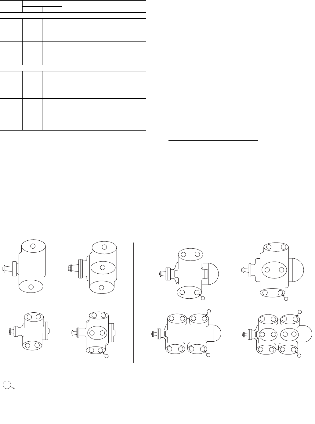
19
Table 15 — Weight Distribution, Compressor
Units (See drawing, Table 14)
LEGEND
NEMA — National Electrical Manufacturers Association
*Oversize frame.
Capacity Control — For all 5F,H compressors, a
pressure-type cylinder unloader is used. On 5F20 and 5F30
compressors, the capacity control valve is external and on 5F40
through 5H126 compressors the valve is located internally. On
all 5F,H compressors, capacity reduction is in response to
suction pressure.
The cylinder unloading mechanism is powered by a
compressor force-feed lubricating system. This feature assures
unloading of all controlled cylinders at starting regardless of
the position of the capacity control valve, since suction valves
will be held in open position until the lubricating oil pressure
reaches its normal operating level. Refer to Fig. 4 for cylinder
unloading sequence.
An external adjusting stem is provided to set control point
and maintain desired suction pressure. The control point is
adjustable from 0 to 85 psig suction pressure. Differential over
the complete range at any temperature level is 10.7 psig with
Refrigerant 22 and Refrigerant 502. A 7-lb spring (for use on
5F40 and larger units) is furnished with the compressor which,
when used, results in an adjustable control point from 0 to
50 psig with a 6.8 psig range. Insert a spring in the capacity
control valve when R-12 is used. See Fig. 5.
With this arrangement, suction pressure will not drop below
the control set point minus the differential within range of
capacity steps since the compressor will unload to balance its
capacity with evaporator load.
Power elements and valve lifting mechanisms are identical
on all 5F,H compressors. However, when using capacity con-
trol, various methods are used to activate the power elements.
See Table 16 for unloading steps and power requirements at
each step.
5F20 AND 5F30 (Fig. 6)
Major Elements of Control Systems:
1. Capacity Control Valve: Function is to raise or lower oil
pressure from oil pump in response to refrigerant suction
pressure.
2. Power Elements: Function is to supply power necessary
to operate valve lifting mechanism. It is modulated by the
capacity control valve.
3. Valve Lifting Mechanism: Consists of a sleeve and push
pin assembly around each controlled cylinder, designed
to hold the suction valve open, or to permit the valve to
remain in a normal operating position depending on its
actuation by the power element.
COMPR WT DISTR (lb) NEMA FRAME SIZE
A or D B or C
Belt Drive
5F20 115 100 182T, 184T, 213T, 215T
5F30 140 118 184T, 213T, 215T, 254T
5F30* 168 145 184T, 213T, 215T, 254T
5F40 228 165 213T, 215T, 254T, 256T
5F60 280 210 215T, 254T, 256T, 284T
5H40 410 305 256T, 284T, 286T, 324T, 326T
5H60 515 395 286T, 324T, 326T
5H60* 630 533 324T, 326T, 364T, 365T
5H80 685 558 324T, 326T, 364T, 365T, 404T
5H120 1050 728 364T, 365T, 404T
Direct Drive
5F40 210 145 213T, 215T, 254T, 256T
5F60 245 185 215T, 254T, 256T, 284T, 286T
5F60* 290 255 256T, 284T, 286T
5H40 380 275 256T, 284T, 286T, 324TS, 326TS
5H46 380 275 324TS, 326TS, 364TS, 365TS
5H80 480 360 286T, 324TS, 326TS, 364TS
5H60 480 360 365TS, 404TS
5H66 480 360 286T, 324TS, 326TS, 364TS, 365TS,
404TS
5H80 690 605 324TS, 326TS, 364TS, 365TS, 404TS
5H86 690 605 365TS, 404TS, 405TS
5H120 890 690 364TS, 365TS, 404TS, 405TS, 444TS
5H126 890 690 405TS, 444TS, 445TS
21
43
21
3
4
3322
22
11
334
4
21
43
1
32
1
2
1
5F30
5F20
5F40 5F60 5H80, 86 5H120, 126
5H40, 46 5H60, 66
AB
1
—Cylinders recommended for permanently unloaded operation. NOTE: The numerals indicate the unloading sequence and
the number of cylinders that unload with each step.
SHORT-STROKE COMPRESSORS ONLY
Fig. 4 — Cylinder Unloading Sequence
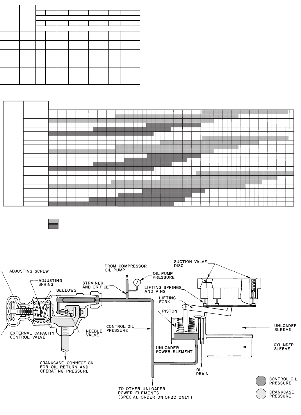
20
Table 16 — Capacity Control Reduction Steps
*Two controlled cylinders (to 331/3%) available on request for 5F30.
Principle of Operation of the System — An increase in suc-
tion gas pressure, which requires increased compressor
capacity, causes the needle valve to close. Therefore, lubrica-
tion oil pressure in power element increases. Increased oil
pressure in power element moves the power piston upward and
the suction valve discs are allowed to seat.
Table 17 indicates control oil pressure at which controlled
cylinders start to and completely unload.
Different points of control pressure on 5F30 are obtained by
using springs with different loading rates in the power element.
COMPR
MODEL
CONTR
CYL
CAP. STEPS (% Full Load Cap.)
100 871/2831/375 662/3621/250 371/2331/325
% Full Load Bhp
10090 868074 716050 4538
Number of Active Cylinders
5F20 12—————1———
5F30* 13———2——— ——
5F40 34——3——2——1
5F60 46—5—4—3—2—
5H40 34——3——2——1
5H46 34——3——2——1
5H60 46—5—4—3—2—
5H66 46—5—4—3—2—
5H80 687——— 5—3—2
5H86 687——— 5—3—2
5H120 812—10 —8—6—4—
5H126 812—10 —8—6—4—
0 1.0 2.0 3.0 4.0 5.0 6.0 7.0 8.0 9.0 10.0 11.0
L
L
L
L
L
L
L
L
L
L
L
L
L
L
L
L
L
U
U
L
U
U
U
U
UNIT
SIZE
REDUCTION
STEPS
1
2
3
4
1
2
3
4
3
1
2
3
1
2
3
1
2
5F40
5H40
5H46
5F60
5H60
5H66
5H80
5H86
4
1
2
3
4
U
U
U
U
U
U
U
U
U
U
5H120
5H126
PSI DIFFERENTIAL
R-22 & 502, R507/404A; 11-LB RANGE ADJUSTMENT SPRING
L - LOAD
U - UNLOAD
U
L
L
L
L
U
U
U
U
U
R-12, R-134a; 7-LB RANGE ADJUSTMENT SPRING
Fig. 5 — Operating Sequence of Capacity Reduction Steps
Fig. 6 — Capacity Control — 5F20, 5F30
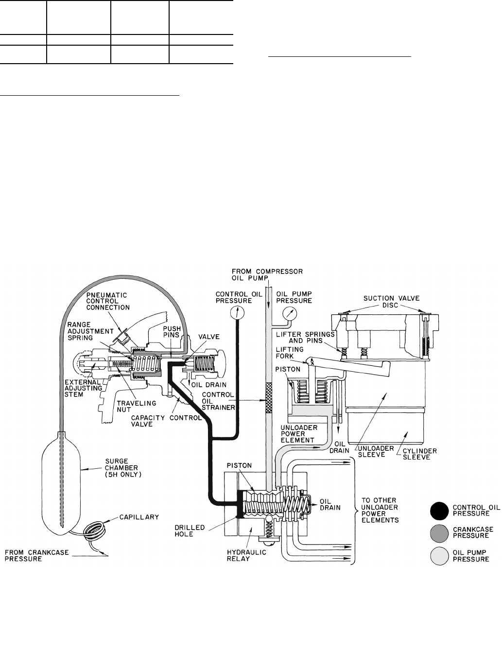
21
Table 17 — Initial and Final Unloading
Oil Pressures — 5F20, 5F30
5F40 THROUGH 5H86 (Fig. 7)
Major Elements of Capacity Control Systems:
1. Capacity Control Valve: Function is to raise or lower the
control oil pressure to the hydraulic relay piston in
response to refrigerant suction pressure. Increase in
suction pressure increases control oil pressure in the hy-
draulic relay.
2. Hydraulic Relay: Function is to feed lubrication oil from
the oil pump at full pressure in sequence to one or more
power elements. Relay is activated by control oil pressure
from the capacity control valve.
3. Power Element: Supplies power to operate the valve
lifting mechanism.
4. Valve Lifting Mechanism: Consists of a sleeve and push
pin assembly around each controlled cylinder, designed
to hold the suction valve open, or to permit the valve to
remain in a normal operating position depending on its
actuation by the power element.
Principle of Operation of the System — A decrease in suc-
tion gas pressure, which necessitates a decrease in compressor
capacity, causes the range spring to open the capacity control
modulating valve. This allows control oil to relieve from the
hydraulic relay and thus reduces control oil pressure in the
relay. With reduced control oil pressure, the spring in the
hydraulic relay moves a piston and thus lubrication oil from the
oil pump is prevented from flowing to a particular deactivated
power element. This relieves oil pressure from the power
element allowing the spring in the power element to move the
lifting fork and unload the cylinder. An increase in suction
pressure reverses action and loads cylinders.
COMPR
NO. OF
CONTROLLED
CYLINDERS
START TO
UNLOAD
OIL PRESS.
(psi)
COMPLETELY
UNLOADED
OIL PRESS.
(psi)
5F20 1 19.8 13.0
5F30 1 30.0 20.2
2 19.8 13.0
Fig. 7 — Capacity Control — 5F40, 60; 5H40, 46, 60, 66, 80 and 86
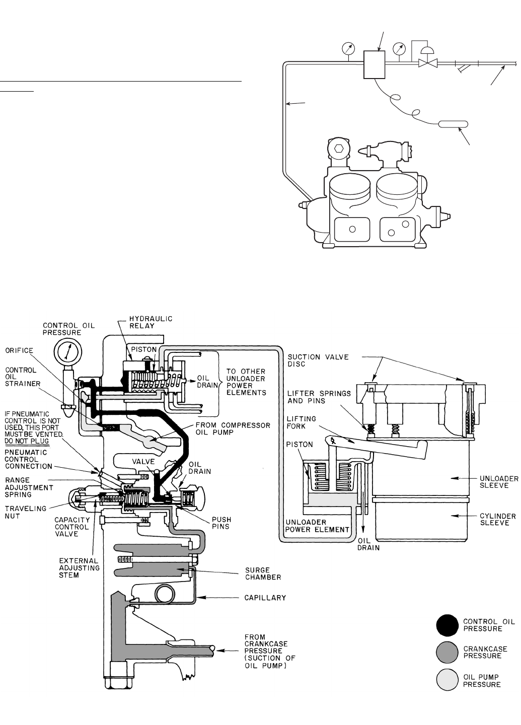
22
5H120, 5H126 CAPACITY CONTROL (Fig. 8) — This ca-
pacity control system is slightly different from the system on
5F40 through 5H86 compressors. Unloaded starting and capac-
ity reduction is obtained by holding open the suction valves of
a number of cylinders. For capacity control purposes, a
suction-pressure-actuated capacity control valve pilots a
hydraulic relay that loads or unloads cylinders in pairs.
Major Difference from the 5F40 through 5H86 Capacity
Control:
1. The hydraulic relay design provides a wider pressure
differential between cylinder cut-in and cutout points.
The relay is a small, easily removed cartridge rather than
an integral part of pump end cover.
2. The surge chamber on 5H120 and 5H126 is an integral
part of the bearing head casting.
PNEUMATIC COMPENSATION OF COMPRESSOR
CAPACITY CONTROL — Adding a control air line to the
external pneumatic control connection permits pneumatic
resetting of the control point in accordance with changes in
operating conditions. Each pound of change in air pressure
resets the control one pound in the same direction. Thus, a one-
pound rise in air pressure will cause unloading to begin at a
suction pressure one pound higher than the original control
point, etc. Figure 9 shows a typical pneumatic control arrange-
ment. All components and installation instructions are field
supplied.
Fig. 8 — Capacity Control — 5H120, 5H126
CONTROL
AIR
SENSING
BULB
3 TO 15 PSI
SIGNAL TO
COMPRESSOR
PNEUMATIC CONTROLLER
OUTPUT TO INCREASE ON
DECREASE IN CONTROLLED
TEMPERATURE
Fig. 9 — Pneumatic Compensation

23
Control Pressurestats — Dual pressurestats are furnished with
all 5F,H compressors. They are often referred to as high- and
low-pressure cutouts. Their function is to cut the circuit to the
holding coil of the compressor motor starter when pressure
setting limits are exceeded.
The high pressurestat has an operating range from 50 to
450 psig with a differential range from 170 to 235 psig (adj).
The low pressurestat has an operating range from 20 in. Hg to
60 psig and a differential range from 60 to 90 psig (adj).
Pressurestat settings should be adjusted on the job to meet
particular operating conditions for which the compressor(s)
have been selected. Directions for setting these pressurestats
are in the 5F,H Installation Instructions.
Permanently Unloaded Cylinders — Operation of an open-
drive compressor with its cylinders permanently unloaded
requires field modification. The 5F60, 5H40 and 5H60 com-
pressors can operate with one cylinder unloaded; 5H80 and
5H120 compressors can operate with 2 cylinders unloaded.
Compressors are modified by removing the suction valve and
suction valve springs from the cylinder(s) shown in Fig. 4.
ELECTRIC SOLENOID VALVE CAPACITY CON-
TROL — Closer control of a conditioned space or medium
can be realized by activating the cylinder unloaders directly in
response to an external step controller activated by solenoid
valves. A temperature sensing controller activates the electric
solenoid valves. Refer to Fig. 10 for an operating concept using
an external electric solenoid-type capacity control. All compo-
nents external to the compressor must be field supplied. Modi-
fications required for standard sequence are as follows:
5F20 and 5F30 Compressors — Modifications are not
required to the 5F20 and 5F30 compressors. See Fig. 4 and 11.
Securely attach a ported solenoid valve to compressor to mini-
mize line vibration. Connect a 1/4-in. steel tubing or high-
pressure flexible hose, KA73RR025, between the compressor
and solenoid valve.
5F40 and 5F60 Compressors
1. Remove the capacity control handhole cover. Remove the
hydraulic relay and all tubing. As shown on Fig. 12, drill
and tap 3 holes on the bottom side of the cover and 2 on
the front. No hole is required at point A on 5F40 com-
pressors. Plug 5 cover holes that connected cover to the
relay. Plugs are 1/8 NPT.
2. Install cover with a new cover gasket 5F40-1042.
3. Mount solenoid valves on a sturdy bracket attached to the
handhole cover using stud bolts on the compressor.
4. Connect external oil lines as shown in Fig. 12 and 13.
Steel tubing and compression fittings are recommended.
5H40 Through 5H86 Compressors — Standard compressors
5H40 through 5H86 built after Serial No. G103460 (July 1971)
may be modified for electric solenoid unloading without addi-
tional machining. Proceed as follows: (See Fig. 4, 13, 14,
and 15).
1. Remove pump end cover only from the compressor.
2. Using the pump end cover gasket (Part No. 5H40-1423)
as a guide, make a blank metal disc (1/32 to 1/16-in. thick),
making holes for bolts only.
3. Reinstall the pump end cover using 2 new 5H40-1423
gaskets, one on each side of the blank disc. This isolates
the capacity control cover.
4. Mount solenoid valves and run oil lines.
5. To minimize vibration, mount the valves on a bracket
attached to the compressor.
5H120, 126 Compressors — Following modifications are
required to electrically unload 5H120, 126 compressors.
1. After closing the compressor service valves and reducing
refrigerant pressure to the atmosphere, remove pump end
bearing head.
2. Remove hydraulic relay assembly by removal of two
5/16-in.-18 socket head screws. Make a blank metal disc
using a hydraulic relay gasket (5H120-3351) as a guide.
Using 1/32 to 1/16-in. thick metal, cut holes in the disc for
dowel pins only. (Do not cut five 9/32-in. diameter holes.)
Reinstall relay assembly using 2 new 5H120-3351
gaskets, one on each side of the metal disc. Torque
5/16-in. socket head screws evenly to 16 to 20 lb-ft.
3. Reinstall the bearing head using extreme care not to
damage the oil pump tang. Align with recess in the end of
the crankshaft. Do not force on.
4. Mount solenoid valves and run oil lines. See Fig. 4, 13,
and 16.
5. To minimize vibration, mount the valves on a bracket
attached to the compressor.
Valves — The following 3-way valves have been used in the
field and are listed as a guide:
• Alco Controls No. 702RA001.
• Also Controls No. S608-1.
• Sporlan Type 180.
SENSING
BULB
MOTOR
2-STEP SEQUENCE
CONTROLLER
SOLENOID
VALVE
CLUSTER
PROPORTIONING TYPE
ELECTRIC CONTROLLER
12
TO OIL COOLER
MAGNETIC PLUG
OIL FILLER PLUG
1/4” NPT OIL PUMP
PRESS. CONN.
SOLENOID
VALVE
3/8” NPT OPENING TO
CRANKCASE
Fig. 10 — External Solenoid-Type
Capacity Control
Fig. 11 — 5F20 and 5F30 Compressor
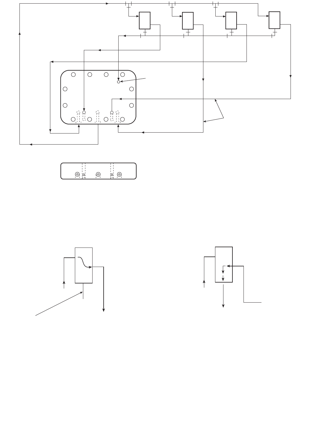
24
2
2R* 1R
1
1L
3
2L
4
BD
CE
A*
PUMP OIL PRESS.
DUMP TO
CRANKCASE
OIL TO UNLOADER
POWER ELEMENTS
*STEP 2R DOES NOT EXIST ON
A 5F40 COMPRESSOR. NO HOLE
IS REQUIRED AT POINT A
FRONT VIEW
BOTTOM VIEW HANDHOLE COVER (ALL PIPE PLUGS 1/8 NPT)
FROM UNLOADER
CONNECTIONS
WHEN UNLOADING DESIRED,
SOLENOID VALVE SHOULD ALLOW
OIL FROM UNLOADERS TO DUMP INTO
OIL SUMP.
A
B
C
THIS
PORT
CLOSED
TO UNLOADER CONNECTIONS. OIL
PRESSURE LOADS THIS STEP WHEN
SOLENOID VALVE ALLOWS FLOW AS
SHOWN.
THIS PORT
CLOSED
A
B
C
FROM HIGH
SIDE OF
OIL PUMP
Fig. 12 — 5F40 and 5F60 Compressors
Fig. 13 — Recommended Solenoid Valve Operation
A
DEENERGIZED, FLOW A-B LOADS STEP
B
ENERGIZED, FLOW B-C UNLOADS STEP
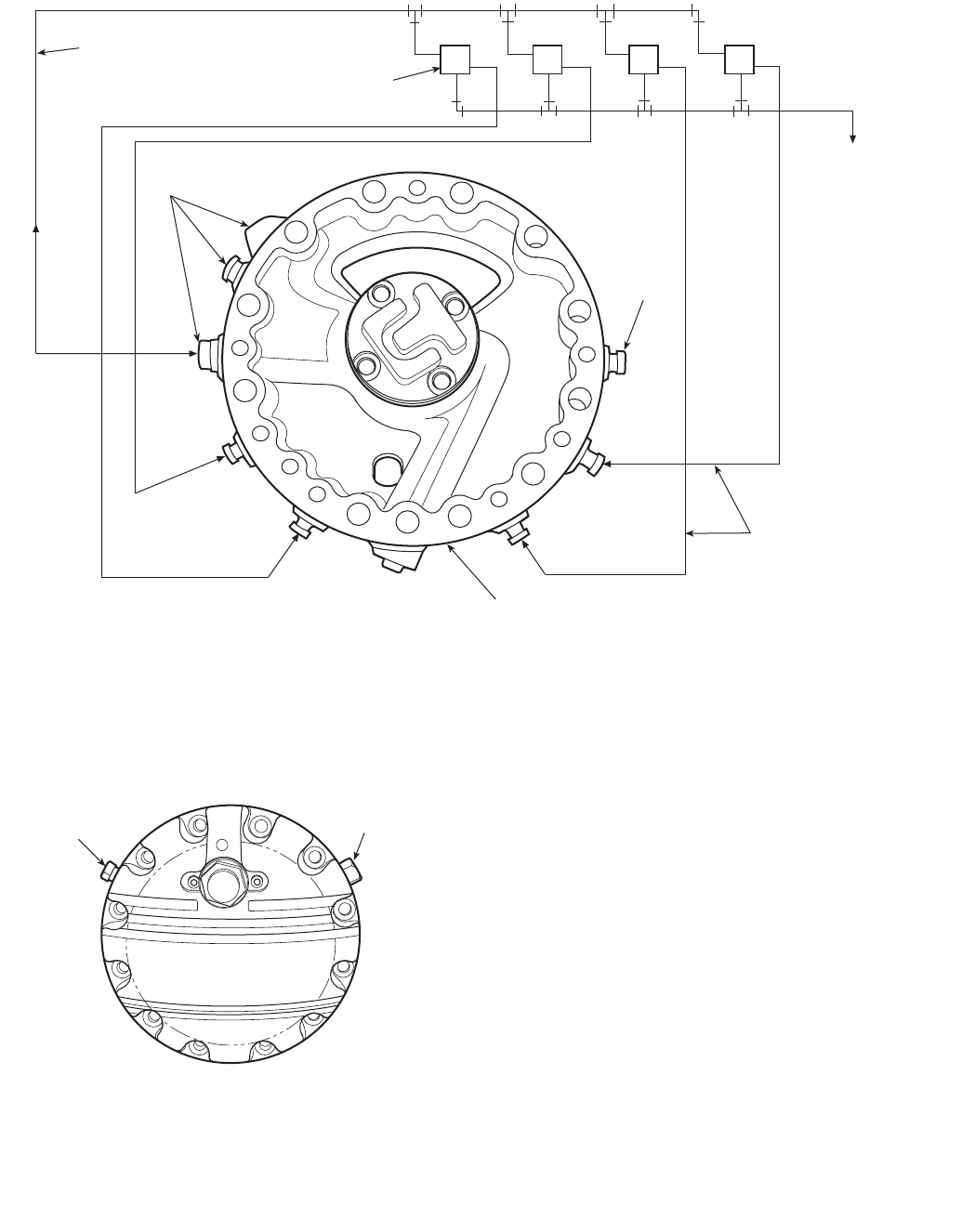
25
CAPACITY CONTROL MODIFICATIONS FOR HEAT
PUMP APPLICATION — Where 5F40, 5F60, and 5H com-
pressors are used in refrigerant cycle reversing heat pump
applications, it is usually necessary to modify the standard
capacity control arrangement to satisfy unloading require-
ments. On summer cycle, the compressor is required to unload
as circulating water or air temperature drops. During winter
cycle, the control works in reverse, so that the compressor
unloads as the circulating water or air temperature increases. It
is necessary for the compressor to unload in response to either
a summer or winter temperature-sensing device, depending on
the particular cycle in operation.
Where summer and winter design suction temperatures are
within design range of either electric or pneumatic compensa-
tion devices, capacity control may be external. However,
another means is normally required.
Usually modification to the compressor capacity control
system is required. The compressor can be modified in 2 ways:
(1) for applications requiring 50% capacity reduction; (2) for
applications requiring more than one step of capacity reduc-
tion. See Fig. 10 for a typical 2-step external capacity control
arrangement.
UNLOADER PUMP
TO CRANKCASE
(CONNECTION ON
PUMP END COVER)
SEE FIG. 15
OIL TO UNLOADER
1/4 NPT (FOUR PLACES)
PUMP END BEARING HEAD
2
4
*STEP #2 IS OMITTED ON 5H40 COMPRESSOR
3
3/8 NPT
3-WAY SOLENOID VALVE
SEE FIG. 13
PUMP OIL
PRESSURE 4321
*
1/4 NPT
1
Fig. 14 — 5H40, 46, 60, 66, 80, 86 Bearing Head
TO DUMP CONTROL OIL BACK INTO OIL RESERVOIR USE
EITHER CONNECTION
1/4”-18 NPT 5/8”-18 NF
Fig. 15 — 5H40, 46, 60, 66, 80, 86
Pump End Cover Assembly
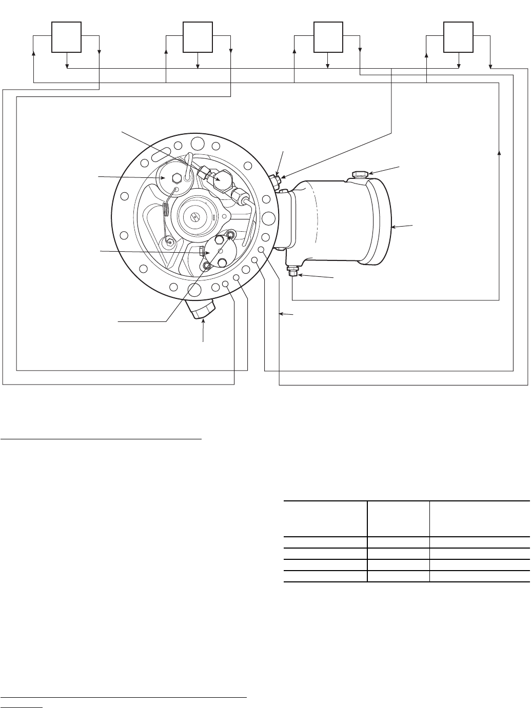
26
Application Requiring 50% Capacity Reductions — This is
the usual specification for heat pump applications and should
cover majority of cases. The necessary modifications to com-
pressor capacity control can be accomplished by ordering the
compressor with factory modifications and then completing
modification at the jobsite with field-supplied components.
Factory Modifications — The compressor order should state
that compressor is to be special for heat pump application, and
is to include only enough unloader power elements to unload
the compressor down to 50% displacement. The unloaded
cylinders will be those closest to pump end of the compressor.
Field Completion — Install a 1/4-in. or 3/8-in. bypass line
between the control oil pressure connection and the crankcase
and install a solenoid valve in this line.
The cylinders set up for unloading may be loaded or unload-
ed by operation of this solenoid valve. When the solenoid valve
is closed, full oil pressure is available to the controlled
cylinders and these will be loaded so that compressor will be
operating on 100% capacity. When the solenoid valve is open,
oil pressure will be bled from the controlled cylinders and they
will be unloaded, so that compressor will then be operating at
50% capacity. A 2-step thermostat controlling the compressor
can thus utilize 2 capacity steps by operating the compressor
starter and solenoid bypass valve.
Application Requiring More Than One Step of Capacity
Reduction — This can be furnished on special order for com-
pressors having 6, 8, or 12 cylinders. Arrangement consists of
furnishing a compressor with external solenoid unloading type
capacity control. The control can be furnished with or without
3-way valves (Table 18).
Table 18 — Capacity Control Steps and
Heat Pump Modification
Hot Gas Bypass — Hot gas bypass may be required on
some systems for one of the following reasons:
1. Frequent operation at loads below minimum capacity
(compressor fully unloaded).
2. To avoid low-load compressor cycling on the low-
pressure switch. Excessive cycling can reduce equipment
life and increase demand charges.
3. Specifications call for hot gas bypass (better humidity
control, etc.).
COMPRESSOR
EXTERNAL
3-WAY
SOLENOID
VALVES
AVAILABLE
CAPACITY STEPS
(%)
5F40, 5H40, 5H46 3 100, 75, 50, 25
5F60, 5H60, 5H66 4 100, 83.3, 66.7, 50, 33.3
5H80 4 100, 87.5, 62.5, 37.5, 25
5H120, 5H126 4 100, 83.3, 66.7, 50, 33.3
CAPACITY CONTROL VALVE
SURGE CHAMBER
HYDRAULIC RELAY
REMOVE THESE ALLEN
HEAD SCREWS TO
REMOVE HYDRAULIC
RELAY.
MAGNETIC PLUG
(PUMP INTAKE)
4
2
3
1OIL PUMP PRESSURE
(AFTER FILTERING)
UNLOADER SEQUENCE 1/8” NPT CONNECTION.
OIL PRESSURE LOAD THESE STEPS.
TO UNLOAD, DUMP CONTROL OIL BACK INTO OIL
RESERVOIR THROUGH CRANKCASE & OIL FILL
CONNECTION.
OIL PUMP PRESS
(BEFORE FILTERING)
FULL FLOW
FILTER HOUSING
3-WAY SOLENOID VALVES
SEE FIG. 13 FOR RECOMMENDED OPERATION.
UL
#2
UL
#1
UL
#3
UL
#4
CRANKCASE
& OIL FILL
CONNECTION
1/8” NPT
Fig. 16 — 5H120 and 126 Bearing Head Assembly

27
The variety of systems using 5F,H compressors make it
impractical to cover all aspects of hot gas bypass operation.
The following guidelines will aid in determining the proper
application.
The hot gas bypass valve is basically a pressure regulating
valve installed to hold a constant compressor suction pressure.
It should operate over as small a pressure range as possible.
The normal set point of the valve should be coordinated with
cylinder unloaders so that the bypass valve starts to open at a
pressure where the last cylinder bank unloads, and is fully open
at a slightly lower pressure. Types, ratings and published appli-
cation guides for various available valves must be evaluated to
determine the proper valve and installation practice for each
application.
If a compressor system is to operate down to zero load, the
valve capacity should equal compressor capacity when fully
unloaded. For systems using multiple evaporators, it may be
necessary to use multiple hot gas valves.
Hot gas should be taken from a point as close as possible to
compressor discharge and fed through a hot gas solenoid valve
and then through a hot gas valve. The hot gas solenoid valve
can be controlled by a pressure switch or temperature switch.
On compressors equipped with an electrically actuated cylinder
unloader, the hot gas solenoid should be wired in parallel with
the solenoid that unloads the final cylinder bank so that bypass-
ing starts immediately when all cylinders are unloaded.
HOT GAS INJECTION INTO LIQUID LINE — When
amount of bypass is small and the evaporator has a low pres-
sure drop distribution system and existing system piping does
not present problems, hot gas is frequently injected into the
liquid line between the thermostatic expansion valve (TXV)
and the evaporator. The ideal point for hot gas injection is into
the side inlet of a side connection distributor, where inlet is
downstream of distributor orifice. If too much hot gas is
injected upstream of a distributor orifice, gas binding and
erratic expansion valve operation will result. Injection into
liquid line is recommended whenever practical, since agitation
in the evaporator and normal operation of the TXV will tend to
thoroughly desuperheat injected hot gas and prevent compres-
sor overheating.
HOT GAS INJECTION INTO COMPRESSOR SUCTION —
Hot gas injection into compressor suction is sometimes neces-
sary but must be done with caution to ensure sufficient
desuperheating of hot gas and to prevent liquid slugging in the
compressor. Following guidelines should be observed:
1. Inject hot gas as close as possible to the evaporator outlet.
2. Install a TXV bulb at least 3 or 4 ft (further if possible)
downstream from the hot gas injection point to ensure
good gas mixing before the bulb.
3. Install a separate small TXV to inject liquid refrigerant
into the suction line along with bypass gas. This valve
should have capacity approximately 25% of hot gas
valve capacity since hot gas must be superheated but not
condensed.
4. Install a suction (knockout) drum in the suction line
immediately before the compressor and downstream of
the hot gas inlet and liquid injection inlet. Only larger
industrial systems or systems with many remote evapora-
tors can normally justify the extra expense of injecting
hot gas into the compressor suction.
Motor Selection Data — Motor selection data based on
brake horsepower occurring at design operating condition is
usually satisfactory for applications in air conditioning suction
temperature range.
Required compressor starting torque is dependent on dis-
charge pressure as well as pressure differential occurring
during start-up and is the same for any compressor speed.
Values shown in Table 19 indicate maximum starting torque
for R-12, R-134a, R-22, R-502, and R-507/404A. In most
cases, a standard torque motor can be selected because of
the partially unloaded starting feature of the 5F and 5H
compressors.
In selection of a motor, the required motor starting torque
must exceed the compressor starting torque only when the
compressor is operating at same speed as the motor. If com-
pressor speed is less than motor speed, as on some belt drive
units, the motor starting torque requirements are reduced in
proportion to the speed ratio between the compressor and
motor because of mechanical advantage available to the motor.
In special applications or systems where there is a large
pulldown requirement, the bhp requirement during pulldown
may significantly exceed bhp at design conditions. The motor
must not be overloaded during pulldown operation. If the
motor is sized for pulldown, it will be only partially loaded
during design operation and will run inefficiently. Therefore,
select a motor that will be optimized for system design require-
ments and not for pulldown requirements. Two ways for
handling this are:
1. Install a crankcase pressure regulator in the system to
maintain a given saturated suction temperature, thereby
controlling bhp requirement, or
2. Install a current sensing device so that the motor current
draw does not exceed the maximum rated motor current.
Drive Packages — Table 20 indicates drive package
components for 5F,H standard belt drive packages. Figure 17
and Tables 21 and 22 indicate data for the flywheel used in
each of these packages.
Table 19 — Compressor Starting Torques
COMPRESSOR
SIZE
%
UNLOADING
DURING
STARTING
SATURATED DISCHARGE TEMPERATURE (F)
80 F 100 F 120 F
R-12,
R-134a R-22 R-502,
R-507/404A
R-12,
R-134a R-22 R-502,
R-507/404A
R-12,
R-134a R-22 R-502,
R-507/404A
Maximum Starting Torque (lb-ft)
5F20 None 19 30 32 27 42 45 34 53 57
5F30 None 22 34 37 30 47 50 39 61 65
5F40 75 18 28 30 25 39 42 32 50 53
5F60 662/322 34 37 30 47 50 39 61 65
5H40 75 42 65 70 57 89 95 74 115 123
5H46 75 53 81 87 71 111 119 92 144 154
5H60 662/351 79 85 69 107 115 90 140 149
5H66 662/364 99 106 86 134 144 113 175 186
5H80 75 58 90 96 79 123 130 102 158 169
5H86 75 73 113 120 99 154 162 127 197 212
5H120 662/391 141 151 123 191 204 160 249 266
5H126 662/3114 176 189 154 239 255 200 311 332

28
Table 20 — Belt Drive Packages
LEGEND
NOTE: Compressor shaft diameter before taper begins:
5F20, 30 = 1.0 in.
5F40, 60 = 1.5 in.
All 5H = 2.0
DRIVE PACKAGE
PART NUMBER
COMPR
SIZE HP FRAME
SHAFT
DIAM
(in.)
COMPR
RPM
CENTER
TO
CENTER
(in.)
FLYWHEEL PULLEY BELTS
Pkg No. OD Pkg No. PD Pkg No.
No.
of
Belts
5F20-A181 5F20 3 182T 11/81750 19.3 5F20-394 7.5 5F20-861 7.4 5F20-851 2
5F20 5 184T 11/81750 19.3 5F20-394 7.5 5F20-861 7.4 5F20-851 2
5F30 5 184T 11/81750 19.3 5F20-394 7.5 5F20-861 7.4 5F20-851 2
5F20-A191 5F20 3 182T 11/81450 20.2 5F20-394 7.5 5F20-881 6.2 5F20-851 2
5F30 5 184T 11/81450 20.2 5F20-394 7.5 5F20-881 6.2 5F20-851 2
5F20-A201
5F20 7.5 213T 13/81750 19.3 5F20-394 7.5 5F20-891 7.4 5F20-851 2
5F20 10 215T 13/81750 19.3 5F20-394 7.5 5F20-891 7.4 5F20-851 2
5F30 7.5 213T 11/81750 19.3 5F20-394 7.5 5F20-891 7.4 5F20-851 2
5F30 10 215T 13/81750 19.3 5F20-394 7.5 5F20-891 7.4 5F20-851 2
5F20-A211
5F20 7.5 213T 13/81450 20.2 5F20-394 7.5 5F20-901 6.2 5F20-851 2
5F30 7.5 213T 13/81450 20.2 5F20-394 7.5 5F20-901 6.2 5F20-851 2
5F30 10 215T 13/81450 20.2 5F20-394 7.5 5F20-901 6.2 5F20-851 2
5F30-A201 5F30 15 254T 15/81750 19.3 5F30-394 7.5 5F30-921 7.4 5F30-831 3
5F40-A181
5F40 7.5 213T 15/81750 26.6 5F40-394 9.5 5F30-881 9.4 5F40-841 3
5F40 10 215T 13/81750 26.6 5F40-394 9.5 5F30-881 9.4 5F40-841 3
5F60 10 215T 13/81750 26.6 5F40-394 9.5 5F30-881 9.4 5F40-841 3
5F40-A191
5F40 7.5 213T 13/81450 25.5 5F40-394 9.5 5F40-891 8.0 5F30-841 3
5F40 10 215T 13/81450 25.5 5F40-394 9.5 5F30-891 8.0 5F30-841 3
5F60 10 215T 13/81450 25.5 5F40-394 9.5 5F30-891 8.0 5F30-841 3
5F40-A201
5F40 15 254T 15/81750 26.6 5F40-394 9.5 5F40-871 9.4 5F40-841 3
5F40 20 256T 15/81750 26.6 5F40-394 9.5 5F40-871 9.4 5F40-841 3
5F60 15 254T 15/81750 26.6 5F40-394 9.5 5F40-871 9.4 5F40-841 3
5F60 20 256T 15/81750 26.6 5F40-394 9.5 5F40-871 9.4 5F40-841 3
5F40-A211
5F40 15 254T 15/81450 25.5 5F40-394 9.5 5F30-901 8.0 5F30-841 3
5F60 15 254T 15/81450 25.5 5F40-394 9.5 5F30-901 8.0 5F30-841 3
5F60 20 256T 15/81450 25.5 5F40-394 9.5 5F30-901 8.0 5F30-841 3
5F60-A191 5F60 25 284T 17/81750 26.6 5F40-394 9.5 5F40-881 9.4 5F40-841 3
5F60-A211 5F60 25 284T 17/81450 25.5 5F40-394 9.5 5F40-891 8.0 5F30-841 3
5H40-911 5H40 20 256T 15/81750 32.2 5H40-394 11.0 5H40-811 11.0 5H40-861 3
5H40-921 5H40 20 256T 15/81450 30.7 5H40-394 11.0 5H60-811 9.0 5H60-861 3
5H40-931
5H40 25 284T 17/81750 32.2 5H40-394 11.0 5H80-811 11.0 5H40-861 3
5H40 30 286T 17/81750 32.2 5H40-394 11.0 5H80-811 11.0 5H40-861 3
5H60 30 286T 17/81750 32.2 5H40-394 11.0 5H80-811 11.0 5H40-861 3
5H40-941
5H40 25 284T 17/81450 30.7 5H40-394 11.0 5H120-811 9.0 5H60-861 3
5H40 30 286T 17/81450 30.7 5H40-394 11.0 5H120-811 9.0 5H60-861 3
5H60 30 286T 17/81450 30.7 5H40-394 11.0 5H120-811 9.0 5H60-861 3
5H40-951
5H40 40 324T 21/81750 32.2 5H40-394 11.0 5H40-821 11.0 5H40-861 3
5H40 50 326T 21/81750 32.2 5H40-394 11.0 5H40-821 11.0 5H40-861 3
5H60 40 324T 21/81750 32.2 5H40-394 11.0 5H40-821 11.0 5H40-861 3
5H40-961
5H40 40 324T 21/81450 30.7 5H60-394 11.0 5H60-821 9.0 5H80-861 5
5H40 50 326T 21/81450 30.7 5H60-394 11.0 5H60-821 9.0 5H80-861 5
5H60 40 324T 21/81450 30.7 5H60-394 11.0 5H60-821 9.0 5H80-861 5
5H60 50 326T 11/81450 30.7 5H60-394 11.0 5H60-821 9.0 5H80-861 5
5H60-921 5H60 50 326T 21/81750 32.2 5H60-394 11.0 5H80-821 11.0 5H120-861 5
5H60-931
5H80 60 364T 23/81750 36.7 5H60-394 11.0 5H120-821 11.0 5H40-871 5
5H80 75 365T 23/81750 36.7 5H60-394 11.0 5H120-821 11.0 5H40-871 5
5H120 60 364T 23/81750 36.7 5H60-394 11.0 5H120-821 11.0 5H40-871 5
5H120 75 365T 23/81750 36.7 5H60-394 11.0 5H120-821 11.0 5H40-871 5
5H60-941 5H60 60 364T 23/81750 32.8 5H60-394 11.0 5H120-821 11.0 5H120-861 5
5H60 75 365T 23/81750 32.8 5H60-394 11.0 5H120-821 11.0 5H120-861 5
5H80-911 5H80 40 324T 21/81750 36.7 5H60-394 11.0 5H80-821 11.0 5H40-871 5
5H80 50 326T 21/81750 36.7 5H60-394 11.0 5H80-821 11.0 5H40-871 5
5H80-921 5H80 40 324T 21/81450 38.2 5H60-394 11.0 5H60-821 9.0 5H40-871 5
5H80 50 326T 21/81450 38.2 5H60-394 11.0 5H60-821 9.0 5H40-871 5
5H80-931 5H80 60 364T 23/81450 38.2 5H60-394 11.0 5H60-831 9.0 5H40-871 5
5H120 60 364T 23/81450 38.2 5H60-394 11.0 5H60-831 9.0 5H40-871 5
5H80-941 5H80 75 365T 23/81450 38.2 5H80-394 11.0 5H80-831 9.0 5H80-871 6
5H120-941 5H120 75 365T 23/81450 38.2 5H120-394 11.0 5H80-831 9.0 5H80-871 6
5H80-951 5H80 100 404T 27/81750 36.7 5H120-394 11.0 5H120-831 11.0 5H120-871 9
5H120 100 404T 27/81750 36.7 5H120-394 11.0 5H120-831 11.0 5H120-871 9
5H120-911 5H120 100 404T 27/81450 38.2 5H120-394 11.0 5H40-841 9.0 5H120-871 9
PD —Pitch Diameter (in.)
29
Table 21 — Flywheel Data
*Refer to Fig. 17.
Table 22 — Flywheel — Compressor Dimensions
*Refer to Fig. 17.
BOOSTER COMPRESSORS FOR
REFRIGERANT 12, 22, 502, AND 507/404A
Booster Application Data — The following data sup-
plements the single-stage compressor application data, and
adds information pertaining to booster application only. Refer
to the single-stage compressor data for all other information.
Rating Basis — All booster ratings* are given in refriger-
ation effect and are based on:
1. Use of a liquid-suction heat interchanger. All liquid-
suction interchangers should have a bypass connection on
the liquid side so that adjustment can be made in event
that too much superheating of suction gas causes exces-
sive heating of compressor. This is especially true for
Refrigerant 22, which has a higher compression exponent
than Refrigerant 12.
2. The liquid refrigerant at Point A (Fig. 18) at satu-
ration temperature corresponds to booster discharge
pressure. This is often referred to as saturated inter-
mediate temperature.
This occurs when booster discharge gas is condensed in a
cascade (refrigerant-cooled) condenser, or when using an
open flash-type intercooler in a direct staged system.
When subcooling of liquid takes place in a closed-
type intercooler, it is not possible to bring liquid tempera-
ture down to saturated intermediate temperature because
of temperature difference required for heat transfer
through the liquid coil. In this case, the compressor rating
must be decreased 3% for each 10 degrees that liquid
temperature at Point A is above the saturated intermediate
temperature.
3. Use of only half of the standard number of suction valve
springs per cylinder. All 5F,H compressors are factory
assembled with the standard number of suction valve
springs; therefore, one-half of the springs per cylinder
must be removed in the field for booster applications.
4. Booster ratings are based on a 1750 rpm compressor
speed.
*R-507/404A ratings are similar to R-502.
“R” Factors — In a multistage compression system, the
intermediate or high-stage compressor must have sufficient
capacity to handle the low-stage (booster) compressor load
plus heat added to refrigerant gas by a low-stage machine
during compression. Likewise, if an intermediate stage com-
pressor should be used, the high-stage compressor must have
sufficient capacity to handle the intermediate stage compressor
load plus heat added to the refrigerant gas by an intermediate
stage machine during compression.
To assist in the selection of higher stage compressors,
Table 23 presents “R” factors that depict approximate required
relationship between stages at various saturated temperature
conditions.
To determine the required capacity of a higher stage com-
pressor, multiply lower stage compressor capacity by the
proper “R” factor from Table 23. Any additional loads handled
at intermediate pressure must be added to this figure to arrive at
the total higher stage load.
Multistage System Pointers — A staged system is
essentially a combination of 2 or more simple refrigerant
cycles. In combining 2 or more simple flow cycles to form a
staged system for low temperature refrigeration, 2 basic types
of combinations are common (Fig. 18).
DIRECT STAGING — Involves use of compressors, in
series, compressing a single refrigerant.
CASCADE STAGING — Usually employs 2 or more refrig-
erants of progressively lower boiling points. Compressed
refrigerant of low stage is condensed in an exchanger (cascade
condenser) that is cooled by evaporation of another lower
pressured refrigerant in the next higher stage.
Safety Factors — Use of capacity safety factors in select-
ing booster compressors must be a matter of judgment when
making selection.
Factors that have a bearing on satisfactory compressor
selections are: accuracy of load estimate, amount of safety
factor included in the total load, degree of importance of meet-
ing specified capacity at given condition, temperature level of
operation and magnitude of refrigeration load. All of the
factors must be recognized when considering the use of a
capacity safety factor in selecting a booster compressor.
Figure 19 presents reasonable safety factors for use in selec-
tion of booster compressors. These can be employed when it is
not desired to establish a factor based on selector’s judgment.
FLYWHEEL
PACKAGE
NUMBER
FLYWHEEL
MODEL
WIDTH
A (in.)*
OD
C (in.)*
PITCH
DIAM
D (in.)*
GROOVES
(No. and
Type)
5F20-394 5F20-1053 13/48.0 7.5 2-B
5F30-394 5F30-1053 21/28.0 7.5 3-B
5F40-394 5F40-1054 21/210.0 9.5 3-B
5F60-394 5F60-1054 31/810.0 9.5 4-B
5H40-394 5H40-1104 33/811.75 11.0 3-C
5H60-394 5H60-1104 53/811.75 11.0 5-C
5H80-394 5H80-1104 63/811.75 11.0 6-C
5H120-394 5H120-1104 93/811.75 11.0 9-C
COMPRESSOR
MODEL
FLYWHEEL
MODEL
DIMENSIONS
F (in.)*
5F20 5F20-1053 67/8
5F30 5F20-1053 85/8
5F30-1053 83/4
5F40 5F40-1054 105/8
5F60 5F40-1054 115/8
5F60-1054 113/4
5H40 5H40-1104 131/4
5H60-1104 1311/16
5H60 5H40-1104 14
5H60-1104 147/16
5H80
5H40-1104 20
5H60-1104 207/16
5H80-1104 189/16
5H120-1104 215/16
5H120 5H60-1104 2011/16
5H120-1104 219/16
GROOVES
F TO C OF FLYWHEEL
L
C OF COMPRESSOR
L
A
D
C
Fig. 17 — Flywheel

30
When a capacity safety factor is used, the compressor is
selected at its maximum speed to handle design load plus safe-
ty factor. Multiplying factors for non-standard speeds are
shown in Fig. 20.
Whether or not added capacity offered by the safety factor is
incorporated at once is a matter of judgment. If it is, then the
compressor will be operated at maximum speed at the start and
any excess capacity achieved will be reflected in faster
pulldowns or lower temperatures. It is also a good practice to
drive the machine at a speed that will provide slightly more
rated capacity than is required by design load. Additional
speed-up available will then constitute reserve capacity in the
event it is needed. Motors should be sized to run the compres-
sor at maximum speed to forestall any motor changes, should
this maximum compressor speed be required in the future.
Fig. 18 — Flow Diagrams for Common Multistage Systems
(Not to be used as Piping Diagrams)
31
Table 23 — Booster “R” Factors
Air-cooled (R-12 and R-22) Water-cooled (R-22 only)
Determining Intermediate Pressure — In applica-
tion of commercial compressors to staged systems, the lowest
total bhp per ton and most economical equipment selection
results when using approximately equal compression ratios for
each stage. It is also economical to juggle assigned compres-
sion ratios to fit available sizes of machines.
The use of Fig. 21 (page 32), will allow direct determination
of proper intermediate pressure that will result in equal com-
pression ratios per stage for a direct 2-stage system. Informa-
tion in Fig. 21 is given in terms of saturated temperature
instead of pressures, for easier use with compressor ratings.
Existence of a second appreciable load, at some higher
suction pressure level, will often dictate the most convenient
intermediate pressure.
Gas Desuperheating — Operation of a direct staged
system requires cooling of the gas between stages; otherwise,
highly superheated discharge gas from low-stage machine
would be taken directly into the suction of higher stage com-
pressor and further compression would result in excessive
heating of this compressor.
Liquid Cooling — It is also necessary to employ liquid
cooling between stages and increase refrigeration effect of
liquid delivered to evaporator to realize rated capacity of boost-
er compressor. Amount of refrigeration expended in cooling
liquid between stages is accomplished more economically at
the level of high-stage compressor suction than at the level of
low-stage suction.
Three common methods of gas desuperheating and liquid
cooling for direct stage systems are illustrated in Fig. 18. In
open-type systems, refrigerant liquid is cooled down to the
saturation temperature corresponding to intermediate pressure.
In closed-type systems, good intercooler design usually results
in refrigerant liquid being cooled down to 10 to 20 degrees
above saturation temperature corresponding to intermediate
pressure.
Oil Separators and Lubrication — In cascade-type
systems, where evaporators and suction lines are properly
designed for oil return to the compressor, oil separators are
usually not used.
In direct stage systems, however, oil may tend to accumu-
late in one of the stages and thus result in lack of lubrication in
other machine. By use of oil transfer lines, equalization of oil
level between crankcases can be achieved by manual operation
at periodic intervals. Automatic control of proper oil return to
both compressors is effected by use of a high stage discharge
line oil separator, returning oil to high stage machine, and a
high side float, connected to high stage machine crankcase,
which continually drains excess oil from this crankcase down
to the next lower stage compressor (Fig. 18).
For booster application, factory oil charge should be drained
and replaced with a suitable viscosity oil for low temperature
application.
SUCT
TEMP
(F)
DISCHARGE TEMPERATURE (F)
–50 –40 –30 –20 –100 102030
R-12
–80 —1.230 1.276 1.328 1.377 1.429 1.470 ——
–70 —1.186 1.230 1.280 1.330 1.380 1.421 1.458 1.489
–60 ——1.183 1.233 1.284 1.334 1.375 1.410 1.441
–50 ———1.189 1.238 1.287 1.328 1.363 1.397
–40 ————1.190 1.240 1.280 1.318 1.350
–30 —————1.291 1.234 1.270 1.307
R-22
–100 1.261 1.310 1.360 1.410 1.453 ————
1.221 1.271 1.319 1.371 1.414 ————
–90 1.214 1.263 1.313 1.361 1.407 1.448 ———
1.175 1.221 1.270 1.321 1.368 1.408 ———
–80 1.170 1.218 1.269 1.315 1.360 1.400 1.434 ——
1.129 1.172 1.221 1.271 1.319 1.359 1.394 — —
–70 —1.172 1.221 1.269 1.313 1.351 1.388 1.424 —
—1.125 1.173 1.221 1.270 1.311 1.348 1.382 —
–60 ——1.178 1.220 1.267 1.303 1.340 1.377 1.406
— — 1.125 1.172 1.221 1.263 1.300 1.337 1.367
–50 ———1.175 1.219 1.256 1.291 1.329 1.360
———1.123 1.173 1.217 1.252 1.289 1.319
–40 ————1.171 1.209 1.245 1.281 1.311
————1.126 1.169 1.205 1.241 1.261
–30 —————1.160 1.199 1.233 1.265
—————1.121 1.159 1.196 1.227
NOTE: For R-502, “R” Factor = 1 + [0.212 x low stage bhp]
low stage capacity (tons)
50
40
30
20
15
10
9
8
7
6
5
4
3
2
1
0.5
510 15 20 30 40 50 60 70
SAFETY FACTOR %
TONS OF REFRIGERATION
SATURATED SUCTION TEMPERATURE F-100
-90
-80
-60
-40
Fig. 19 — Booster Compressor Selection
Safety Factors
MULTIPLYING FACTORS
FOR OTHER SPEEDS
CAPACITY
BHP
100
90
80
70
60
50
1000 1200 1400 1600 1800
SPEED (RPM)
% RATING AT 1750 RPM
Fig. 20 — Multiplying Factors —
Nonstandard Speeds
32
Control Pressurestat for Booster Applica-
tion — The standard dual pressure switch furnished with the
5F,H compressor cannot be used for booster application.
Replace it with an appropriate low temperature dual
pressurestat that can operate at values shown in Table 24. Any
commercial pressure switch is acceptable; for example,
an Allen-Bradley Bulletin 836, type L33 for R-12 or type 1
for R-22.
Table 24 — Control Pressurestats for
Low Stage Application
CHARACTERISTICS R-12 R-22, R-502, OR
R-507/404A
Switch Action —High Open on pressure rise Open on pressure rise
—Low Open on pressure fall Open on pressure fall
Range —High 20″ Vac to 65 psig 30″ Vac to 110 psig
—Low 30″ Vac to 20 psig 30″ Vac to 25 psig
Differential —High 8 to 30 psi adjust. 12 to 30 psi adjust.
—Low 5 to 15 psi adjust. 9 to 30 psi adjust.
Max Pressure —High 200 psig 300 psig
—Low 120 psig 300 psig
-100 -90 -80 -70 -60 -50 -30
-40 -20 -10 0
-100 -90 -80 -70 -60 -50 -30
-40 -20 -10 0
+50
+40
+30
+20
+10
0
-10
-20
+50
+40
+30
+20
+10
0
-10
-20
-30
-40
SATURATED DISCHARGE TEMPERATURE F
SATURATED DISCHARGE TEMPERATURE F
120
110
100
90
80
80
90
100
110
R-502 (SEE NOTE)
R-22R-22
R-12
SATURATED SUCTION TEMPERATURE F
SATURATED SUCTION TEMPERATURE F
SATURATED INTERMEDIATE TEMPERATURE F SATURATED INTERMEDIATE TEMPERATURE F
NOTE: For R-502, lower saturated intermediate temperature is approximately 5 F.
Fig. 21 — Optimum Intermediate Temperature for 2-Stage Compression
(Incorporating Equal Compression Ratios per Stage)

33
Discharge Valve Springs — When 5H compressors
are used for booster applications where discharge pressure is
below 10 psig, the standard discharge valve springs furnished
with the machine should be replaced with an equal number of
lighter weight springs, Part Number 5H41-1801.
No change in discharge valve springs is recommended for
5F compressors.
Water-Cooled Heads — Standard 5F,H compressors
are not equipped with water-cooled heads but they are avail-
able on special order. Water cooling of heads is generally not
necessary in R-12 or R-502 booster applications. For applica-
tions with R-22 involving high compression ratios, 5 or above,
5F,H booster compressors should be equipped with water-
cooled heads.
Motor Selection Data — In staged refrigeration sys-
tems, the high stage compressor starts first and runs until low
stage pressure has been reduced to a predetermined level
before the low stage machine starts. With direct staged arrange-
ments, the high stage machine draws gas from the evaporator
through low stage machine bypass during this initial period.
Size of the selected motor must be related to the maximum
condition at which booster compressor can operate.
Compressor may run under heavy loads during periods of
high suction pressure, especially on starting when system is
warm. To handle these situations the motor must be sized larger
than the actual balanced operation brake horsepower indicates,
or special attention must be paid to operation of the system
when starting initially. Tables 25-27 give balanced brake horse-
power values at 1750 rpm.
If the system is to operate only at a fixed low temperature, it
is possible to avoid oversizing of motors providing careful op-
eration is followed when the system is first put in operation.
On applications requiring reduction from ambient condi-
tions to some extremely low temperature, the compression
system will be operated at high suction pressures for consider-
able periods of time. General practice is to drive the high stage
compressor with a motor that will operate compressor at the
highest expected evaporator temperature. This is generally the
“air conditioning” rating of unit. For intermediate or low stage
compressors, it is generally sufficient to size motor to take care
of double the balance load indicated horsepower plus friction
horsepower.
Also consider compressor starting torque requirements
when selecting motor for a booster compressor. Starting torque
of a motor only large enough to provide required normal
operating bhp for booster applications may not be large enough
to start the compressor. Recommended minimum motor sizes
shown in Table 28 have been selected to assure adequate
starting torque. Actual motor size selected is usually larger,
depending on the maximum bhp conditions under which the
compressor will run during pulldown or other abnormal operat-
ing periods.
It is good practice to select motors with allowance for 10%
voltage reduction unless there is a certainty that this cannot
occur.
Compressor Starting Torque — Required compres-
sor starting torque is dependent on the discharge pressure as
well as the pressure differential occuring during start-up.
Maximum expected torque required during the starting period
for 5F,H compressors, used as boosters, is shown in Table 28 at
2 saturated discharge temperatures.
Selection Procedure — Selection of a 5F,H booster
compressor requires that the load, saturated suction tempera-
ture, saturated discharge temperature, type of system and
refrigerant are known.
After the saturated intermediate temperature is determined
from Fig. 21, the booster rating (Tables 25-27) can be entered
and the compressor selected. Low stage load is then multiplied
by the “R” factor from Table 23 to obtain high stage compres-
sor load. With this information, the Compressor Ratings tables
on pages 7-15, and page 17 can be entered and the high-stage
compressor selected.
SELECTED EXAMPLE:
Given:
Refrigeration Load. . . . . . . . . . . . . . . . . . . . . . . . . . . . . .5.7 tons
Saturated Suction Temperature. . . . . . . . . . . . . . . . . . . . . –60 F
Saturated Condensing Temperature . . . . . . . . . . . . . . . . . . .80 F
Open-Type Intercooler
Refrigerant 22
Find: Compressor size and motor size.
Solution:
1. Figure 21 indicates an optimum saturated intermediate
temperature of –2 F. Allow a 1 degree or 2 degree drop
from the booster compressor to intercooler and from the
intercooler to the high stage compressor.
Booster Saturated Suction Temperature = –60 F
Booster Saturated Discharge Temperature = 0° F
2. At –60 F suction and 0° F discharge, the 5H60 booster
compressor has a capacity of 6.8 tons with 12.1 bhp input
at 1750 rpm.
The safety factor at 1750 rpm:
This is satisfactory from Fig. 19 and a 5H60 compressor
is selected.
3. Indicated hp (ihp) = bhp – Friction hp (fhp)
Where bhp is given in Table 26 and fhp is given in
Table 28.
Indicated hp (ihp) = 12.1 – 3.07 = 9.03
Recommended minimum hp
= (2 x ihp) + fhp
= (2 x 9.03) + 3.07 = 21.13
Tentatively select a 25-hp motor. Assume that low stage
will never start against a saturated discharge higher than
30 F. At 30 F discharge, Table 28 indicates a starting
torque of 54 lb-ft. Therefore, a normal starting torque
25-hp motor is selected.
4. With –60 F suction and 0° F discharge, Table 23 indicates
an “R” value of 1.303. Therefore, the high stage load is:
1.303 x 6.8 = 8.86 tons (actual load)
5. Allowing a 1 degree drop from the intercooler, the high
stage saturation suction temperature is –3 F.
Allowing a 2 degree drop between the compressor and
condenser, the high stage saturated discharge temperature
= 80 + 2 = 82 F.
6. Referring to the 5F,H Compressor Ratings table, 5F60 at
1450 rpm (using multiplier in compressor capacity notes)
has a capacity of 9.21 tons at –3 F suction and 82 F dis-
charge (through interpolation). The 5F60 is selected and
requires 13.0 bhp at 1450 rpm.
7. Assume that maximum load during pulldown occurs at
50 F suction and 90 F discharge. For this condition, the
rating tables (using the multiplier in Step 6) indicate
15.8 bhp, thus a 20-hp motor is selected.
(6.8 )x 100 – 100 = 19.3 or 20%
5.7

34
Table 25 — 5F,H Booster Ratings; R-12
LEGEND
*Also referred to as Saturated Intermediate Temperature.
SST SDT* 5F20 5F30 5F40 5F60
Cap. Bhp Cap. Bhp Cap. Bhp Cap. Bhp
–85
–50 0.28 0.93 0.42 1.30 0.57 1.67 0.85 2.42
–40 0.27 0.94 0.40 1.31 0.54 1.68 0.80 2.43
–30 0.25 0.94 0.38 1.31 0.50 1.69 0.76 2.45
–20 0.24 0.95 0.36 1.33 0.47 1.70 0.71 2.46
–10 0.20 0.95 0.31 1.34 0.40 1.71 0.63 2.49
0 0.180.950.271.350.361.730.552.51
–80
–50 0.34 0.97 0.51 1.36 0.63 1.75 1.00 2.54
–40 0.33 1.00 0.49 1.40 0.65 1.80 0.98 2.61
–30 0.31 1.00 0.47 1.40 0.62 1.80 0.93 2.62
–20 0.30 1.00 0.45 1.41 0.59 1.81 0.89 2.63
–10 0.27 1.00 0.40 1.42 0.54 1.82 0.80 2.64
0 0.241.010.361.420.481.760.722.66
10 0.21 1.01 0.31 1.43 0.42 1.84 0.63 2.67
–70
–40 0.48 1.11 0.72 1.57 0.95 2.03 1.40 2.96
–30 0.46 1.13 0.70 1.60 0.93 2.07 1.40 3.02
–20 0.45 1.14 0.68 1.62 0.90 2.09 1.40 3.05
–10 0.42 1.14 0.63 1.63 0.84 2.10 1.30 3.07
0 0.391.150.581.630.772.111.203.08
10 0.35 1.15 0.53 1.64 0.70 2.12 1.10 3.09
20 0.31 1.16 0.46 1.65 0.60 2.13 0.93 3.11
30 0.27 1.17 0.40 1.66 0.53 2.15 0.80 3.14
–60
–30 0.66 1.27 0.98 1.81 1.30 2.35 2.00 3.44
–20 0.64 1.31 0.96 1.87 1.30 2.43 1.90 3.56
–10 0.61 1.32 0.92 1.89 1.20 2.45 1.80 3.59
0 0.581.330.861.901.202.471.703.62
10 0.54 1.39 0.82 1.99 1.10 2.59 1.60 3.80
20 0.50 1.45 0.75 2.08 1.00 2.71 1.50 3.98
30 0.45 1.35 0.68 1.94 0.90 2.52 1.40 3.69
–50
–20 0.89 1.51 1.30 2.17 1.80 2.83 2.70 4.16
–10 0.86 1.53 1.30 2.20 1.70 2.87 2.60 4.22
0 0.831.561.202.251.702.932.504.31
10 0.79 1.58 1.20 2.28 1.60 2.97 2.40 4.37
20 0.74 1.60 1.10 2.30 1.50 3.01 2.20 4.43
30 0.69 1.61 1.00 2.32 1.40 3.03 2.10 4.46
–40
–10 1.20 1.77 1.80 2.56 2.40 3.35 3.50 4.94
0 1.101.831.702.652.303.473.405.12
10 1.10 1.90 1.70 2.76 2.20 3.61 3.30 5.33
20 1.10 1.90 1.60 2.78 2.10 3.64 3.20 5.38
30 1.00 1.93 1.50 2.80 2.00 3.67 3.00 5.42
–30
0 1.502.172.303.163.104.154.606.14
10 1.50 2.23 2.30 3.25 3.00 4.27 4.50 6.32
20 1.40 2.29 2.20 3.34 2.90 4.39 4.40 6.50
30 1.40 2.34 2.10 3.41 2.80 4.49 4.20 6.65
SST SDT* 5H40 5H46 5H60 5H66
Cap. Bhp Cap. Bhp Cap. Bhp Cap. Bhp
–85
–50 1.30 3.43 1.60 4.46 2.00 5.52 2.50 7.17
–40 1.20 3.46 1.50 4.50 1.90 5.58 2.40 7.25
–30 1.20 3.50 1.50 4.54 1.80 5.63 2.20 7.31
–20 1.10 3.53 1.30 4.59 1.70 5.68 2.10 7.38
–10 1.00 3.58 1.20 4.65 1.50 5.75 1.90 7.47
0 0.88 3.63 1.10 4.72 1.30 5.82 1.60 7.56
–80
–50 1.60 3.64 2.00 4.73 2.40 5.85 3.00 7.60
–40 1.50 3.70 1.80 4.81 2.30 5.93 2.90 7.70
–30 1.50 3.75 1.80 4.87 2.20 6.01 2.70 7.81
–20 1.40 3.81 1.70 4.95 2.10 6.09 2.60 7.91
–10 1.30 3.85 1.60 5.00 1.90 6.15 2.40 7.99
0 1.20 3.88 1.50 5.04 1.70 6.20 2.10 8.06
10 1.00 3.96 1.20 5.15 1.50 6.31 1.90 8.20
–70
–40 2.20 4.27 2.70 5.55 3.40 6.79 4.20 8.82
–30 2.20 4.36 2.70 5.66 3.30 6.92 4.10 8.98
–20 2.10 4.45 2.60 5.78 3.20 7.05 4.00 9.15
–10 2.00 4.49 2.40 5.84 3.00 7.11 3.70 9.23
0 1.90 4.52 2.30 5.87 2.80 7.12 3.50 9.25
10 1.70 4.58 2.10 5.95 2.60 7.25 3.20 9.42
20 1.50 4.65 1.80 6.04 2.30 7.34 2.80 9.53
30 1.30 4.71 1.60 6.12 2.00 7.44 2.50 9.66
–60
–30 3.10 5.12 3.80 6.65 4.70 8.06 5.80 10.48
–20 3.00 5.25 3.70 6.82 4.60 8.25 5.70 10.63
–10 2.90 5.31 3.60 6.90 4.40 8.35 5.50 10.85
0 2.80 5.38 3.50 6.99 4.20 8.44 5.20 10.98
10 2.60 5.43 3.20 7.06 3.90 8.52 4.80 11.08
20 2.40 5.49 3.00 7.14 3.60 8.60 4.50 11.19
30 2.20 5.54 2.70 7.20 3.20 8.69 4.00 11.30
–50
–20 4.20 6.15 5.20 7.99 6.30 9.60 7.80 12.48
–10 4.00 6.30 4.90 8.19 6.10 9.83 7.60 12.78
0 3.90 6.45 4.80 8.38 5.90 10.06 7.30 13.08
10 3.70 6.52 4.60 8.47 5.60 10.24 6.90 13.31
20 3.50 6.62 4.30 8.60 5.20 10.31 6.40 13.40
30 3.30 6.67 4.10 8.80 4.90 10.38 6.10 13.49
–40
–10 5.50 7.43 6.80 8.83 8.30 11.53 10.30 15.00
0 5.40 7.74 6.70 10.05 8.10 11.98 10.00 15.59
10 5.20 7.95 6.40 10.32 7.80 12.30 9.70 15.99
20 5.00 8.04 6.20 10.45 7.40 12.44 9.20 16.19
30 4.70 8.13 5.80 10.58 7.10 12.57 8.80 16.32
–30
0 7.30 9.41 9.00 12.22 11.00 14.50 13.60 18.86
10 7.10 9.65 8.80 12.53 10.60 14.84 13.10 19.30
20 6.80 9.88 8.40 12.83 10.20 15.19 12.70 19.72
30 6.50 10.11 8.00 13.13 9.80 15.54 12.20 20.20
SST SDT* 5H80 5H86 5H120 5H126
Cap. Bhp Cap. Bhp Cap. Bhp Cap. Bhp
–85
–50 2.60 7.37 3.20 9.58 4.00 9.50 5.00 12.35
–40 2.50 7.44 3.20 9.66 3.80 9.70 4.70 12.60
–30 2.40 7.51 3.00 9.76 3.60 9.80 4.50 12.73
–20 2.20 7.58 2.70 9.85 3.40 9.90 4.20 12.88
–10 2.00 7.67 2.50 9.96 3.00 10.00 3.70 13.00
0 1.80 7.76 2.20 10.99 2.70 10.10 3.30 13.93
–80
–50 3.20 7.69 4.00 10.00 4.80 10.20 5.90 13.28
–40 3.10 7.90 3.80 10.28 4.60 10.20 5.70 13.28
–30 2.90 8.01 3.60 10.41 4.40 10.50 5.40 13.66
–20 2.80 8.12 3.50 10.54 4.20 10.70 5.20 13.91
–10 2.60 8.19 3.10 10.64 3.90 10.80 4.80 14.03
0 2.30 8.27 2.80 10.74 3.50 10.90 4.30 14.18
10 2.00 8.42 2.50 10.94 3.00 11.10 3.70 14.42
–70
–40 4.50 9.05 5.60 11.77 6.70 12.10 8.30 15.72
–30 4.30 9.22 5.30 11.98 6.50 11.30 8.10 14.70
–20 4.20 9.40 5.20 12.21 6.30 12.60 7.80 16.39
–10 4.00 9.47 5.00 12.31 5.90 12.70 7.30 16.50
0 3.70 9.55 4.60 12.41 5.60 12.70 7.90 16.50
10 3.40 9.66 4.20 12.56 4.30 13.00 5.30 16.90
20 3.00 9.79 3.70 12.71 4.50 13.20 5.60 17.18
30 2.60 9.92 3.20 12.89 3.90 13.40 4.80 17.42
–60
–30 6.20 10.74 7.70 13.98 9.30 14.60 11.50 18.99
–20 6.10 11.00 7.60 14.30 9.10 15.00 11.30 14.50
–10 5.80 11.13 7.20 14.48 8.70 15.20 10.80 19.77
0 5.60 11.26 6.90 14.62 8.30 15.40 10.30 20.02
10 5.20 11.36 6.40 14.77 7.80 15.50 9.70 20.15
20 4.80 11.47 5.90 14.90 7.20 15.70 8.90 20.40
30 4.30 11.58 5.30 15.06 6.50 15.90 8.10 20.70
–50
–20 8.30 12.80 10.30 16.63 12.50 17.70 15.50 23.00
–10 8.10 13.10 10.10 17.02 12.10 18.20 15.10 23.65
0 7.80 13.41 9.70 17.42 11.70 18.60 14.50 24.19
10 7.40 13.65 9.20 17.73 11.20 19.00 13.90 24.70
20 7.00 13.74 8.70 17.87 10.50 19.10 13.00 24.80
30 6.50 13.84 8.10 18.00 9.80 19.30 12.10 25.10
–40
–10 11.10 15.37 13.80 19.98 16.60 21.60 20.60 28.07
0 10.80 15.98 13.40 20.77 16.20 22.50 20.10 29.21
10 10.40 16.41 12.90 21.36 15.60 23.10 19.30 25.10
20 9.90 16.58 12.30 21.55 14.80 23.40 18.30 30.40
30 10.70 16.76 13.30 21.79 14.10 23.60 17.50 30.70
–30
0 14.60 19.33 18.10 25.16 21.90 27.50 27.10 35.74
10 14.10 19.79 17.50 25.71 21.20 28.20 26.20 34.05
20 13.60 20.26 16.90 26.25 20.50 28.90 25.40 37.55
30 13.00 20.72 16.10 26.94 19.60 29.60 24.30 38.43
Bhp —Brake Horsepower
Cap. —Capacity (Tons)
SDT —Saturated Discharge Temperature (F)
SST —Saturated Suction Temperature (F)

35
Table 26 — 5F,H Booster Ratings; R-22
LEGEND
*Also referred to as Saturated Intermediate Temperature.
†Requires water-cooled heads.
SST SDT* 5F20 5F30 5F40 5F60
Cap. Bhp Cap. Bhp Cap. Bhp Cap. Bhp
–100
–50 0.27 0.95 0.40 1.35 0.54 1.75 0.80 2.25
–40 0.22†1.00 0.33†1.36 0.43†1.75 0.65†2.45
–30 0.18†1.05 0.28†1.38 0.37†1.80 0.55†2.50
–20 0.15†1.10 0.23†1.38 0.30†1.80 0.45†2.60
–10 0.10†1.15 0.15†1.40 0.20†1.85 0.30†2.70
–90
–50 0.42 1.05 0.62 1.53 0.83 1.95 1.40 2.65
–40 0.38 1.11 0.56 1.55 0.75 1.95 1.10 2.75
–30 0.35†1.14 0.53†1.58 0.70†2.00 1.10†2.80
–20 0.29†1.19 0.44†1.59 0.58†2.00 0.88†2.81
–10 0.27†1.24 0.40†1.61 0.54†2.05 0.80†2.90
00.24†1.23 0.36†1.62 0.48†2.10 0.73†3.00
–80
–50 0.63 1.25 0.94 1.80 1.30 2.20 1.90 3.20
–40 0.57 1.25 0.85 1.81 1.10 2.20 1.70 3.25
–30 0.54 1.28 0.81 1.82 1.10 2.25 1.60 3.30
–20 0.50 1.30 0.75 1.85 1.10 2.25 1.50 3.35
–10 0.46†1.33 0.69†1.86 0.92†2.30 1.40†3.40
00.43†1.36 0.65†1.90 0.87†2.30 1.30†3.50
10 0.36†1.39 0.53†1.91 0.71†2.40 1.10†3.50
–70
–40 0.83 1.45 1.20 2.11 1.70 2.70 2.50 3.94
–30 0.79 1.48 1.20 2.15 1.60 2.72 2.40 4.00
–20 0.75 1.50 1.10 2.18 1.50 2.72 2.20 4.05
–10 0.71 1.53 1.10 2.19 1.40 2.80 2.10 4.10
00.67†1.59 1.00†2.20 1.30†2.85 2.00†4.17
10 0.59†1.50 0.89†2.21 1.20†3.00 1.80†4.20
20 0.51†1.55 0.75†2.22 1.00†3.00 1.60†4.42
–60
–30 1.10 1.75 1.70 2.45 2.40†3.30 3.40 4.78
–20 1.10 1.79 1.60 2.48 2.10 3.30 3.20 4.80
–10 1.00 1.82 1.60 2.60 2.10 3.40 3.10 5.00
0 0.99 1.88 1.50 2.62 2.00 3.50 3.00 5.08
10 0.91†1.81 1.40†2.65 1.80†3.60 2.70†5.25
20 0.82†1.82 1.20†2.68 1.60†3.57 2.50†5.29
30 0.73†1.84 1.10†2.70 1.50†3.50 2.20†5.40
–50
–20 1.50 2.12 2.30 3.05 3.00 4.00 4.60 5.50
–10 1.40 2.16 2.20 3.10 2.90 4.10 4.30 6.00
0 1.40 2.10 2.20 3.15 2.90 4.15 4.30 6.19
10 1.30 2.23 2.00 3.25 2.60 4.25 4.00 6.28
20 1.20 2.22 1.90 3.30 2.50 4.30 3.70 6.40
30 1.20†2.28 1.70†3.31 2.30†4.20 3.50†6.50
–40
–10 1.90 2.60 2.90 3.50 3.90 4.88 5.80 7.50
0 1.90 2.50 2.80 3.88 3.80 5.08 5.60 7.68
10 1.80 2.78 2.70 4.17 3.60 5.40 5.40 7.96
20 1.70 2.82 2.60 4.08 3.50 5.40 5.20 8.09
30 1.70 2.85 2.50 4.17 3.30 5.50 5.00 8.19
–30
0 2.40 2.85 3.60 5.19 4.80 7.40 7.30 9.78
10 2.30 3.60 3.50 5.34 4.60 7.58 7.00 10.00
20 2.30 3.62 3.40 5.44 4.50 7.00 6.80 10.10
30 2.20 3.70 3.30 5.47 4.40 7.87 6.60 10.20
SST SDT* 5H40 5H46 5H60 5H66
Cap. Bhp Cap. Bhp Cap. Bhp Cap. Bhp
–100
–50 1.30 3.10 1.60 4.03 1.90 5.50 2.40 7.15
–40 1.10†3.50 1.30†4.55 1.60†5.58 2.00†7.25
–30 0.92†3.50 1.10†4.55 1.40†5.78 1.70†7.50
–20 0.79†3.68 0.97†4.78 1.20†6.00 1.50†7.80
–10 0.67†3.75 0.83†4.87 1.00†6.08 1.20†7.90
–90
–50 1.90 3.70 2.30 4.80 2.90†6.18 3.60 8.03
–40 1.70 3.98 2.10 5.17 2.60 6.40 3.20 8.31
–30 1.60†4.04 2.00†5.25 2.40†6.58 3.00†8.55
–20 1.04†4.09 1.70†5.31 2.10†6.58 2.60†8.55
–10 1.30†4.14 1.60†5.38 2.00†6.65 2.50†8.64
01.20†4.19 1.50†5.44 1.80†6.75 2.20†8.77
–80
–50 2.80 4.49 3.50 5.84 4.30 7.30 5.30 9.48
–40 2.60 4.79 3.20 6.22 3.90 7.50 4.80 9.74
–30 2.40 4.89 3.00 6.35 3.60 7.68 4.50 9.97
–20 2.30 4.94 2.80 6.41 3.40 7.78 4.20 10.10
–10 2.20†5.00 2.70†6.50 3.30†7.88 4.10†10.20
01.90†5.12 2.30†6.65 2.90†7.99 3.60†10.40
10 1.70†5.25 2.10†6.82 2.50†8.00 3.10†10.40
–70
–40 3.80 5.90 4.70†7.66 5.80 9.18 7.20 11.90
–30 3.60 5.98 4.40 7.77 5.40 9.28 6.70 12.10
–20 3.30 5.97 4.10 7.75 5.00 9.28 6.20 12.10
–10 3.30 6.08 4.10 7.90 4.90 9.50 6.10 12.40
03.10†6.19 3.80 8.04 4.60†9.75 5.70†12.70
10 2.70†6.25 3.30†8.42 4.10†10.00 5.10†13.00
20 2.40†6.25 2.90†8.12 3.60†10.10 4.50†13.10
–60
–30 5.20 7.08 6.40†9.19 7.80 11.30 9.70 14.70
–20 4.90 7.28 6.10 9.45 7.40 11.60 9.20 15.10
–10 4.80 7.34 5.90 9.53 7.20 11.80 8.90 15.40
0 4.50 7.70 5.60 10.00 6.80 12.10 8.40 15.70
10 4.10†7.75 5.10†10.05 6.20†12.30 7.70†16.00
20 3.80†7.75 4.70†10.05 5.60†12.30 6.90†16.00
30 3.50†7.87 4.30†10.20 5.20†12.50 6.40†16.30
–50
–20 6.90 8.88 8.50 11.50 10.30 14.00 12.80 18.20
–10 6.80 9.00 8.40 11.70 10.20 14.50 12.60 18.90
0 6.40 9.25 7.90 12.00 9.60 14.60 11.90 19.00
10 6.00 9.50 7.40 12.30 9.30 14.70 11.50 19.10
20 5.60 9.66 6.90 12.60 8.50 15.00 10.50 19.50
30 5.30†9.75 6.60†12.70 7.90†15.10 9.80†19.60
–40
–10 9.00 10.30 11.20 13.40 13.60 17.20 16.90 22.40
0 8.70 11.60 10.50 15.10 13.00 17.70 16.10 23.00
10 8.20 12.00 10.20 15.60 12.30 18.20 15.30 23.60
20 7.90 12.30 9.80 16.00 11.90 18.60 14.80 24.20
30 7.70 12.40 9.50 16.10 11.50 18.90 14.30 24.20
–30
0 11.50 15.10 14.30 19.60 17.20 22.50 21.20 29.20
10 11.10 15.50 13.70 20.10 16.70 23.20 20.70 30.10
20 10.90 15.80 13.50 20.50 16.30 24.00 20.00 31.20
30 10.60 16.10 13.10 20.90 15.90 24.60 19.70 32.00
SST SDT* 5H80 5H86 5H120 5H126
Cap. Bhp Cap. Bhp Cap. Bhp Cap. Bhp
–100
–50 2.50 7.00 3.10 9.10 3.80 9.50 4.70 12.40
–40 2.20†7.25 2.70†9.40 3.30†9.60 4.10†12.50
–30 1.80†7.50 2.20†9.70 2.80†10.10 3.50†13.10
–20 1.60†7.75 2.00†10.10 2.40†10.50 3.00†13.70
–10 1.30†8.12 1.60†10.00 2.00†10.60 2.50†13.80
–90
–50 3.80 8.00 4.70 10.40 5.80 10.90 7.20 14.20
–40 3.40 8.25 4.20 10.70 5.10 11.30 6.30 14.70
–30 3.20†8.50 4.00†11.00 4.80†11.60 5.90†15.10
–20 2.80† 8.87 3.50†11.50 4.30†11.60 5.30†15.10
–10 2.70†9.00 3.30†11.70 4.00†11.80 5.00†15.40
02.30†9.00 2.80†11.70 3.50†12.00 4.30†15.60
–80
–50 5.70†9.50 7.10 12.40 8.50†13.10 10.50 17.10
–40 5.20 10.00 6.40 13.00 7.80 13.50 9.70 17.50
–30 4.80 10.30 5.90 13.40 7.30 13.90 9.00 18.10
–20 4.50 10.50 5.60 13.70 6.80 14.10 8.40 18.30
–10 4.30†10.60 5.30†13.80 6.50†14.30 8.10†18.60
03.80†10.60 4.70†13.80 5.80†14.50 7.20†18.90
10 3.30†10.80 4.10†14.00 5.00†14.50 6.20†18.90
–70
–40 7.70 12.10 9.50 15.70 11.50 16.90 14.30 22.00
–30 7.20 12.50 8.90 16.20 10.80 17.10 13.40 22.00
–20 6.70 12.70 8.30 16.50 10.00 17.10 12.40 22.20
–10 6.50 12.70 8.00 16.50 9.80 17.50 12.20 22.80
06.20†13.00 7.70†16.90 9.30†18.00 11.50 23.40
10 5.40†12.60 6.70†16.40 8.10†18.50 10.00†24.00
20 4.80†13.30 5.90†17.30 7.30†18.70 9.00†24.30
–60
–30 10.40 15.00 12.90 19.50 15.40 21.00 19.10 27.30
–20 9.90†15.20 12.30 19.80 14.80 21.80 18.30 28.40
–10 9.60 15.50 11.90 20.20 14.40 22.00 17.90 28.60
0 9.00 15.80 11.20 20.60 12.60 22.80 15.60 29.60
10 8.20†16.00 10.20†20.80 12.30†23.00 15.30†29.90
20 7.50†16.40 9.30†21.30 11.30†23.00 14.00†29.90
30 6.90†16.50 8.50†21.40 10.40†23.50 12.90†30.60
–50
–20 13.70 18.70 17.00 24.30 20.60 26.50 25.50 34.40
–10 13.50 19.00 16.70 24.70 20.30†27.50 25.20 35.70
0 12.90 19.20 16.00 25.00 19.30 27.70 23.90 36.00
10 12.00 19.50 14.90 25.40 18.10 28.00 22.40 36.40
20 11.30 20.00 14.00 26.00 16.90 28.50 20.90 37.00
30 10.50†20.20 13.00†26.20 15.80†28.80 19.60†37.40
–40
–10 18.00 23.00 22.30 29.80 27.10 33.00 33.50 42.90
0 17.40 23.70 21.60 30.80 26.00 34.00 32.20 44.20
10 16.40 24.20 20.40 31.40 24.50 35.00 30.40 45.40
20 15.90 25.00 19.70 32.50 23.80 38.20 29.50 49.70
30 15.40 25.20 14.10 32.80 23.00 36.20 28.50 47.00
–30
0 22.90 29.00 28.40 37.70 34.40 43.50 42.60 56.50
10 22.20 30.00 27.50 39.00 33.30 45.00 41.30 58.50
20 21.70 31.00 26.90 40.30 35.60 46.50 44.10 60.40
30 21.20 31.20 26.20 40.50 31.80 47.70 39.40 62.00
Bhp —Brake Horsepower
Cap. —Capacity (Tons)
SDT —Saturated Discharge Temperature (F)
SST —Saturated Suction Temperature (F)

36
Table 27 — 5F,H Booster Ratings; R-502
LEGEND
*Also referred to as Saturated Intermediate Temperature.
SST SDT* 5F20 5F30 5F40 5F60
Cap. Bhp Cap. Bhp Cap. Bhp Cap. Bhp
–90
–30 0.6 1.0 0.9 1.6 1.1 1.7 1.7 3.2
–20 0.5 1.0 0.7 1.7 1.0 1.8 1.5 3.3
–10 0.4 1.1 0.6 1.7 0.9 1.9 1.3 3.3
0 0.3 1.0 0.5 1.7 0.7 1.9 1.1 3.3
10 0.3 1.0 0.4 1.5 0.6 1.8 0.9 3.1
20 0.2 0.9 0.3 1.5 0.5 1.7 0.7 2.9
30 0.1 0.8 ——0.3 1.5 0.5 2.6
–80
–30 0.9 1.1 1.3 1.8 1.7 1.9 2.6 3.5
–20 0.8 1.2 1.2 2.0 1.5 2.1 2.3 3.8
–10 0.7 1.3 1.0 2.1 1.4 2.3 2.0 4.0
0 0.6 1.3 0.9 2.1 1.2 2.4 1.8 4.1
10 0.5 1.3 0.8 2.1 1.0 2.4 1.5 4.1
20 0.4 1.3 0.6 2.0 0.9 2.4 1.3 4.0
30 0.3 1.2 0.5 1.9 0.7 2.3 1.0 3.8
–70
–30 1.2 1.2 1.9 2.0 2.5 2.1 3.7 3.8
–20 1.1 1.4 1.7 2.2 2.3 2.4 3.4 3.2
–10 1.0 1.5 1.5 2.3 2.1 2.7 3.1 4.6
0 0.9 1.6 1.4 2.5 1.8 2.9 2.8 4.8
10 0.8 1.6 1.2 2.6 1.6 3.0 2.4 5.0
20 0.7 1.7 1.1 2.6 1.4 3.1 2.1 5.1
30 0.6 1.6 0.9 2.6 1.2 3.1 1.8 5.0
–60
–30 1.7 1.2 2.6 2.0 3.5 2.2 5.2 3.8
–20 1.6 1.4 2.4 2.3 3.2 2.6 4.8 4.4
–10 1.5 1.6 2.2 2.6 3.0 3.0 4.4 5.0
0 1.3 1.8 2.0 2.8 2.7 3.3 4.0 5.5
10 1.2 1.9 1.8 3.0 2.4 3.6 3.6 5.9
20 1.1 2.0 1.6 3.1 2.1 3.8 3.2 6.2
30 0.9 2.1 1.4 3.2 1.9 4.0 2.8 6.3
–50
–20 2.2 1.4 3.3 2.3 4.4 2.6 6.7 4.4
–10 2.1 1.7 3.1 2.7 4.1 3.1 6.2 5.2
0 1.9 2.0 2.8 3.1 3.8 3.6 5.7 6.0
10 1.7 2.2 2.6 3.4 3.4 4.1 5.2 6.6
20 1.5 2.4 2.3 3.6 3.1 4.4 4.7 7.1
30 1.4 2.5 2.1 3.8 2.8 4.7 4.2 7.5
–40
–20 3.0 1.3 4.5 2.2 6.0 2.5 9.0 4.0
–10 2.8 1.7 4.2 2.7 5.6 3.2 8.4 5.1
0 2.6 2.0 3.9 3.2 5.2 3.8 7.7 6.2
10 2.4 2.3 3.6 3.6 4.7 4.4 7.1 7.1
20 2.2 2.6 3.3 4.0 4.3 4.9 6.5 7.9
30 2.0 2.8 3.0 4.3 3.9 5.4 5.9 8.6
–30
–10 3.7 1.6 5.5 2.5 7.4 3.0 11.1 4.6
0 3.4 2.0 5.2 3.1 6.9 3.8 10.3 6.0
10 3.2 2.4 4.8 3.7 6.4 4.6 9.6 7.2
20 2.9 2.8 4.4 4.3 5.9 5.3 8.8 8.4
30 2.7 3.1 4.1 4.8 5.4 6.0 8.1 9.4
SST SDT* 5H40 5H46 5H60 5H66
Cap. Bhp Cap. Bhp Cap. Bhp Cap. Bhp
–90
–30 2.7 6.3 3.4 8.2 4.1 8.7 5.1 11.3
–20 2.4 6.4 3.0 8.3 3.6 8.9 4.5 11.5
–10 2.1 6.4 2.6 8.4 3.1 9.0 3.9 11.6
0 1.8 6.4 2.2 8.3 2.7 8.9 3.3 11.5
10 1.4 6.2 1.8 8.1 2.2 8.6 2.7 11.2
20 1.1 5.9 1.4 7.7 1.7 8.2 2.2 10.7
30 ———— — — — —
–80
–30 4.1 6.9 5.1 8.9 6.1 9.6 7.6 12.4
–20 3.7 7.2 4.6 9.4 5.6 10.1 6.9 13.1
–10 3.3 7.4 4.1 9.6 5.0 10.4 6.2 13.5
0 2.9 7.5 3.6 9.8 4.4 10.6 5.4 13.8
10 2.5 7.5 3.1 9.8 3.8 10.6 4.7 13.8
20 2.1 7.4 2.6 9.6 3.2 10.4 4.0 13.5
30 1.7 7.1 2.1 9.3 2.6 10.0 3.2 13.0
–70
–30 5.9 7.3 7.3 9.5 8.8 10.3 11.0 13.3
–20 5.4 7.9 6.7 10.3 8.1 11.1 10.1 14.4
–10 4.9 8.3 6.1 10.8 7.4 11.8 9.2 15.3
0 4.4 8.7 5.5 11.3 6.6 12.3 8.2 16.0
10 3.9 8.9 4.9 11.5 5.9 12.6 7.3 16.4
20 3.4 8.9 4.2 11.6 5.2 12.8 6.4 16.6
30 2.9 8.8 3.6 11.5 4.4 12.7 5.5 16.5
–60
–30 8.3 7.5 10.2 9.8 12.3 10.6 15.3 13.7
–20 7.7 8.4 9.4 10.9 11.4 11.9 14.2 15.4
–10 7.0 9.1 8.7 11.8 10.5 13.0 13.1 16.8
0 6.4 9.7 7.9 12.6 9.6 13.9 11.9 18.0
10 5.8 10.2 7.2 13.2 8.7 14.6 10.8 19.0
20 5.2 10.5 6.4 13.7 7.8 15.1 9.7 19.6
30 4.6 10.7 5.7 13.9 6.9 15.4 8.6 20.0
–50
–20 10.5 8.3 12.9 11.1 15.6 12.1 19.4 15.7
–10 9.8 9.6 12.0 12.5 14.5 13.7 18.0 17.8
0 9.0 10.6 11.1 13.7 13.4 15.2 16.7 19.7
10 8.2 11.4 10.1 14.8 12.3 16.4 15.3 21.3
20 7.5 12.0 9.2 15.6 11.2 17.4 13.9 22.6
30 6.7 12.5 8.3 16.2 10.1 18.1 12.5 23.5
–40
–20 14.1 8.2 17.3 10.7 20.9 11.7 26.0 15.2
–10 13.2 9.7 16.2 12.7 19.6 13.9 24.3 18.1
0 12.2 11.1 15.1 14.4 18.2 16.0 22.6 20.7
10 11.3 12.3 13.9 16.0 16.9 17.8 20.9 23.1
20 10.4 13.3 12.8 17.3 15.5 19.3 19.2 25.1
30 9.4 14.1 11.7 18.4 14.1 20.6 17.5 26.8
–30
–10 17.4 9.3 21.3 12.1 25.8 13.3 32.1 17.3
0 16.3 11.1 20.0 14.5 24.2 16.0 30.0 20.8
10 15.1 12.8 18.6 16.6 22.5 18.5 28.0 24.1
20 14.0 14.2 17.2 18.5 20.9 20.7 25.9 27.0
30 12.9 15.5 15.9 20.2 19.2 22.7 23.9 29.5
SST SDT* 5H80 5H86 5H120 5H126
Cap. Bhp Cap. Bhp Cap. Bhp Cap. Bhp
–90
–30 5.4 11.6 6.8 15.1 8.2 17.0 10.1 21.8
–20 4.8 11.9 6.0 15.4 7.2 17.4 9.0 22.4
–10 4.2 12.0 5.2 15.5 6.3 17.5 7.8 22.6
0 3.6 11.8 4.4 15.4 5.3 17.3 6.6 22.3
10 2.9 11.5 3.7 15.0 4.4 16.8 5.4 21.7
20 2.3 11.0 2.9 14.3 3.5 16.0 4.3 20.6
30 ————————
–80
–30 8.2 12.8 10.2 16.6 12.3 18.8 15.2 24.2
–20 7.4 13.5 9.2 17.5 11.1 19.8 13.8 25.5
–10 6.6 13.9 8.2 18.1 9.9 20.5 12.3 26.4
0 5.8 14.1 7.2 18.4 8.7 20.8 10.8 26.8
10 5.0 14.1 6.3 18.4 7.5 20.8 9.4 26.8
20 4.3 13.9 5.3 18.1 6.4 20.4 7.9 26.3
30 3.5 13.4 4.4 17.4 5.2 19.6 6.5 25.4
–70
–30 11.8 13.7 14.6 17.8 17.7 20.1 21.9 25.9
–20 10.8 14.8 13.4 19.3 16.2 21.9 20.1 28.2
–10 9.8 15.7 12.2 20.4 14.8 23.2 18.3 29.9
0 8.9 16.4 11.0 21.3 13.3 24.2 16.5 31.3
10 7.9 16.8 9.8 21.9 11.8 24.8 14.7 32.1
20 6.9 17.0 8.6 22.1 10.3 25.1 12.8 32.4
30 6.0 16.9 7.4 21.9 8.9 24.9 11.1 32.2
–60
–30 16.4 14.1 ——————
–20 15.2 15.8 18.9 20.5 22.9 23.2 28.4 30.1
–10 14.0 17.3 17.4 22.5 21.1 25.5 26.1 32.9
0 12.8 18.5 15.9 24.0 19.2 27.4 23.9 35.3
10 11.6 19.4 14.4 25.3 17.4 28.8 21.6 37.2
20 10.4 20.1 12.9 26.1 15.6 29.8 19.4 38.5
30 9.2 20.5 11.4 26.6 13.8 30.3 17.1 39.2
–50
–20 20.9 16.2 25.9 21.0 31.3 23.8 38.9 30.7
–10 19.4 18.3 24.1 23.8 29.1 27.1 36.1 35.0
0 17.9 20.2 22.2 26.3 26.9 29.9 33.3 38.6
10 16.4 21.8 20.4 28.3 24.6 32.3 30.6 41.8
20 14.9 23.1 18.5 30.0 22.4 34.2 27.8 44.3
30 13.4 24.0 16.7 31.3 20.2 35.7 25.0 46.2
–40
–20 27.9 15.6 34.6 20.2 41.9 22.9 52.0 29.6
–10 26.1 18.6 32.4 24.1 39.2 27.4 48.6 35.5
0 24.3 21.3 30.2 27.6 36.5 31.5 45.3 40.7
10 22.5 23.6 27.9 30.7 33.8 35.1 41.9 45.3
20 20.7 25.7 25.6 33.4 31.0 38.1 38.5 49.3
30 18.8 27.4 23.4 35.6 28.3 40.7 35.1 52.7
–30
–10 34.5 17.7 42.7 23.1 51.7 26.1 64.2 33.9
0 32.3 21.4 40.0 27.8 48.4 31.6 60.1 40.9
10 30.0 24.7 37.3 32.1 45.1 36.6 56.0 47.4
20 27.8 27.6 34.5 35.9 41.8 41.0 51.8 53.1
30 25.6 30.2 31.8 39.2 38.5 44.9 47.7 58.1
Bhp —Brake Horsepower
Cap. —Capacity (Tons)
SDT —Saturated Discharge Temperature (F)
SST —Saturated Suction Temperature (F)

37
Table 28 — Booster Compressor Starting Data
*Based on 1750 rpm with 5F,H compressors. Will vary directly with rpm at other speeds.
CONDENSERS
Condenser Physical Data — Refer to Table 29. Re-
fer to 5F,H Product Data for information on the current
P701 water-cooled condensers used with the 5F,H water-
cooled condensing units.
Condenser Selection Considerations — On most
installations the condenser is selected within recommended
conditions specified in ARI Standards. Main consider-
ations are:
1. The water velocity is within a range of 1 to 12 ft per
second (to minimize corrosion and erosion).
2. It is good practice to select condensers on a leaving tem-
perature difference between 6 and 12 degrees. In general,
higher temperature differences are used only where con-
densing water temperature is quite low or where special
conditions make it economical to do so. A high tempera-
ture difference not only makes effect of fouling more
pronounced but since the condenser volume is likely to be
small, the effect on noncondensable gases will be greater.
Table 30 lists maximum water velocities from Carrier
System Design Manual. Limits are above ARI recommended
values but are generally accepted where ARI conformance is
not specified. See Part 5 of the Carrier System Design Manual
for further details.
Table 31 lists condenser water quantities (gpm) for water
velocities from 3 to 12 fps. For higher velocities, use formulas
below Table 31.
Condenser Duty — The capacity of a given compressor
is greatest at high saturated suction temperatures. Because of
this, the compressor normally requires the largest condenser at
these conditions or for air conditioning duty.
On refrigeration or low temperature applications, the same
compressor displacement results in a lower refrigeration
capacity and, consequently, less heat rejection. Thus, con-
denser size is smaller than would normally be required with the
same compressor on air conditioning duty.
Condenser size is also affected by refrigerant used, since
compressor capacities (and thus heat rejection) differ with
Refrigerants 12, 22, and 502.
Pulldown — Condensers for systems subject to pulldown
periods, especially low temperature or multistage systems,
should be oversized beyond the capacity required at the final
balanced load condition. The condenser must adequately
handle load during the first stages of pulldown, when system
capacity is substantially greater than at final condition.
If pulldown load is sizable, as in most water or brine cooling
applications, check the condenser performance when it is
handling total heat rejection at maximum rated suction temper-
ature (50 F for most compressors). Condenser size and water
quantity must be adequate to handle this start-up load without
resulting in excessive head pressure or excessive water pres-
sure drop. As a rough guide, the selected condenser should
have a maximum total heat rejection rating that is equal to
or greater than the compressor heat rejection at pulldown
conditions.
If this pulldown occurs infrequently, it may be possible to
select a condenser for design conditions and on each start-up
limit compressor capacity by manually throttling suction gas
flow. This can be done by partially closing suction valve but
this will extend time required to reach design conditions.
If the pulldown is of short duration, such as on a direct
expansion coil, suction temperature will drop very rapidly and
more than likely design conditions will be reached before the
compressor would cut out on high pressure. No oversizing of
the condenser would be required.
Whenever possible, the selected condenser should never be
of a larger size than the largest condenser that will match the
compressor used and still be a standard combination. This
should be considered especially when the condensers are to be
used with 5F,H series open reciprocating compressors.
Fouling and Fouling Factors — Fouling in con-
denser tubes is result of a build-up of scale within tubes
because of impurities in water. As a result, heat transfer is
adversely affected. Fouling factors are a means of identifying
degree of fouling.
Condensers should not be selected for less than 0.0005 foul-
ing factor, even when high quality water is available. For lower
quality water, use larger fouling factors from the condenser
ratings, but temper factor according to operating conditions.
The following affect magnitude of fouling factor selected:
• Percentage of yearly operating time.
• Frequency of tube cleaning.
• Condensing temperature.
• Type of water treatment.
For instance, reduce fouling factor when the operating time
is less than 4000 hours per year, when frequent cleaning of
tubes takes place, or when low condensing temperatures exist.
COMPR
SIZE
UNLOADING
DURING
STARTING
MAX COMPR STARTING TORQUE (lb-ft) RECOMMENDED MIN MOTOR SIZE HP
FRICTION
HP*
(fhp)
R-12 R-22 or R-502 R-12 R-22 or R-502
Saturated Discharge Temperature (F) High
Torque
Normal
Torque
High
Torque
Normal
Torque
10 F 30 F 10 F 30 F
5F20 None 91315 21—233.67
5F30 None101516243355.91
5F40 75%812131933551.15
5F60 662/3%101516 24 3 5 57
1/21.64
5H40 75%192830 45 57
1/271/210 2.25
5H46 75%243538 567
1/210 10 15 2.25
5H60 662/3%233437 547
1/210 10 15 3.07
5H66 662/3%294346 68101515203.07
5H80 75%263841 60101520203.82
5H86 75%334851 75152020303.82
5H120 662/3%416065 94152020305.25
5H126 662/3% 51 75 81 118 20 30 30 40 5.25
38
Table 29 — Condenser Physical Data
LEGEND NOTES:
1. Based on R-22 at 105 F condensing, 85 F entering water temperature,
10 F rise. The 09RH097 is rated at 10.6 F rise in order to stay within the
recommended water velocity range.
2. 90 F liquid, 80% filled.
3. Purge and liquid test cocks furnished on all condensers.
4. 5F40 and larger condensers have cleanable and renewable tubes.
Table 30 — Max Condenser Tube Water Velocity
Table 31 — Condenser Gpm at Various Water Velocities*
LEGEND
*Within ARI Standard recommendations.
†Double circuit for 5F20 and 30.
**Single circuit for 5F20 and 30.
Water velocity formulas: (Use for velocities above 12 fps.)
CONDENSER SIZE 5F20 5F30 5F40 5F60 09RH
027
09RH
043
09RH
054
09RH
070
09RH
084
09RH
097
09RH
127
NOMINAL CAPACITY (Tons) 9.8 14.3 22.1 27.3 47.0 71.0 87 103 120 135 198
CONDENSER TYPE Shell and Coil Shell and Tube
Net Weight (lb) 77 114 246 340 493 686 807 863 1028 1360 1635
SHELL
Outside Diameter (in.) 83/883/885/885/8103/4123/4123/4123/414 14 18
Length (in.) 285/8395/863 74 771/8791/4951/4951/4993/81231/81001/2
TUBES OR COIL Coil Tubes; Integral Fin; 40 Fins per Inch
Number (Total) 2 2 26 30 44 66 66 80 94 94 156
Length (in.) 2951/43875/8565/8675/8705/32 705/32 865/32 865/32 865/32 1097/8865/32
No. of Water Circuits 2 or 1 2 or 1 2 or 1 2 or 1 2 or 1 2 or 1 2 or 1 2 or 1 2 or 1 2 or 1 2 or 1
No. of Water Passes ——4 or 8 4 or 8 3 or 6 3 or 6 3 or 6 3 or 6 3 or 6 3 or 6 3 or 6
CIRCUIT LENGTH (ft)
Single Circuit 49.2 64.6 — — — ——— — — —
Double Circuit (each) 24.6 32.3 — — — ——— — — —
Minimum (4 or 3 Pass) ——18.0 21.6 17.0 16.9 20.9 20.9 20.8 26.7 20.8
Maximum (8 or 6 Pass) ——36.0 43.3 34.0 33.8 41.8 41.8 41.6 53.4 41.6
SURFACE
AREA (sq ft)
Water Side 8.6 13.4 20.5 30.7 48.8 70.8 87.7 108.4 130.3 165.2 207.7
Refrig Side 43.6 65.8 66.4 99.5 158.0 229.0 284.0 352.0 422.5 536.3 672.4
MAX WORK.
PRESS. (psig)
Water Side 150 250
Refrig Side 385
MAX REFRIG
STORAGE
CAP. (lb)
R-12 30 41 80 94 163 217 268 239 309 397 527
R-22 27 37 74 86 148 197 243 226 280 360 478
R-502 28 38 75 87 150 200 247 229 284 366 485
MIN REFRIG
OPERATING
CHARGE (lb)
R-12 2.0 3.0 14.0 16.0 37.0 41.0 51.0 51.0 78.0 100 126
R-22 1.8 2.7 12.7 14.5 33.0 37.0 46.0 46.0 71.0 91 114
R-502 1.9 2.9 13.1 15.0 34.4 38.2 47.3 47.3 73.0 94 118
WATER
CONN (in.)
Single
Ckt or
Min Pass
Inlet 1/2 FPT 3/4 FPT (2) 11/4 FPT (2) 11/4 FPT (2) FPT (2) 2 FPT (2) 2 FPT (2) 2 FPT (2) 21/2 IPS (2) 21/2 IPS (2) 3 IPS
Outlet 1/2 FPT 3/4 FPT 11/2 FPT 11/2 FPT 21/2 FPT 3 FPT 3 FPT 3 FPT 4 IPS 4 IPS 5 IPS
Double
Ckt or
Max Pass
Inlet (2) 1/2 FPT (2) 3/4 FPT 11/4 FPT 11/4 FPT 2 FPT 2 FPT 2 FPT 2 FPT 21/2 IPS 21/2 IPS 3 IPS
Outlet (2) 1 MPT (2) 1 MPT 11/4 FPT 11/4 MPT 2 FPT 2 FPT 2 FPT 2 FPT 21/2 IPS 21/2 IPS 3 IPS
REFRIG
CONN
Gas
Inlet
Typ e Female-Solder
ODF (in.) 11/813/813/815/821/825/831/831/831/835/835/8
Liquid
Outlet
Typ e Female-Solder 2-Bolt Valve 4-Bolt Valve
ODF (in.) 1/21/27/811/813/813/815/815/821/821/821/8
RELIEF VALVE (in.) 3/8 MPT 3/8 MPT 1/2 FPT 1/2 FPT 5/8 FL 5/8 FL 5/8 FL 5/8 FL 3/4 FL 3/4 FPT (2) 3/4 FPT
WATER DRAIN & VENT PLUG (in.) —— 1/41/43/83/83/83/83/83/83/8
WATER REG CONN (in.) 1/4
FL —Flare
FPT —Female Pipe Thread (in.)
IPS —Iron Pipe Size (Butt-welded connection)
MPT —Male Pipe Thread (in.)
ODF —Outside Diameter Female (in.)
Psig —Pounds Per Square Inch Gage
OPERATING HOURS
PER HOUR
MAXIMUM TUBE
WATER VELOCITY
(fps)
Up to 1500 15.0
2000 14.0
3000 13.0
4000 12.0
6000 10.0
8000 8.0
CONDENSER
MINIMUM PASS†MAXIMUM PASS**
Water Velocity (fps)
3579101235791012
5F20 61115202224 3 5 8101112
5F30 81522293232 4 7 11141616
5F40 16 27 39 50 56 64 8 14 19 25 28 32
5F60 20 35 50 65 72 80 10 17 25 32 36 40
09RH027 42 70 98 126 140 168 21 35 49 63 70 84
09RH043 63 105 147 189 210 252 31.5 52.5 73.5 94.5 105 126
09RH054 63 105 147 189 210 252 31.5 52.5 73.5 94.5 105 126
09RH070 79 131 183 236 262 316 39.5 65.5 91.5 118 131 158
09RH084 93 155 216 279 310 372 46.5 77.5 108 139.5 155 186
09RH097 93 155 216 279 310 372 46.5 77.5 108 139.5 155 186
09RH127 148 247 346 445 494 592 74.0 123.5 173 222.5 247 296
ARI —Air Conditioning and Refrigeration Institute 5F20 Condenser: V = gpm x 0.92
no. of circuits
5F40 through 09RH127: V = gpm x passes x 1.06
total tubes
5F30 Condenser: V = gpm x 0.65
no. of circuits
39
Water Circuiting Arrangements — The water cir-
cuiting arrangement selected for 5F and 09RH condensers
depends on available condenser water pressure, temperature,
quantity and source. Refer to Table 32.
Refer to the Carrier System Design Manual for specific
information and recommendations for refrigerant and water
piping.
Economics — Selection of a condenser requires balancing
of certain economic variables, including:
1. First cost of compressor-condenser combination.
2. Operating costs.
3. Ratio between power costs and water costs.
Where first cost is the most important consideration, the
best combination of compressor and condensers has the lowest
total equipment cost.
If owning and operating costs are important, combination
must be selected on basis of both considerations.
A condenser selection that permits operation of the system
at a low condensing temperature, results in the lowest compres-
sor motor brake horsepower and consequently, lowest operat-
ing cost. A condenser selection that is heavily loaded requires
the compressor to operate at a higher condensing temperature
and results in higher compressor motor brake horsepower and
operating cost.
For a given compressor-condenser combination, selection
of a condensing temperature may depend on a ratio between
power costs and water costs, on quantity of water available,
on condensing temperature required to achieve compressor
capacity, or a requirement to remain within allowable loading
on a given motor size.
Condenser Performance with Ethylene Gly-
col — Increased use of closed circuit cooling towers has led
to a corresponding increase in the need for shell and tube con-
denser ratings for use with ethylene glycol. When towers are
installed outdoors, a brine solution is required for freeze protec-
tion during winter operations.
In most outdoor installations, specifications will call for a
percentage of concentration of ethylene glycol or other brine
solution. If concentration is not specified, it may be the choice
of the contractor to determine a percentage of glycol concentra-
tion to ensure against freeze-up during winter minimum design
ambients.
To perform simplified selection, use Fig. 22 to convert a
condenser water rating to a brine rating.
EXAMPLE:
Assume that a building with a year-round cooling load has a
cooling requirement of 120 tons during summer design condi-
tions. Chilled water design temperatures are 54 F entering to
44 F leaving, and for summer duty, the condenser water is
based on 85 F and a 10 degree rise.
From product literature, selected unit will deliver 121 tons
at 105.8 F saturated discharge temperature (SDT) and has
153 tons of heat rejection.
Determine condenser loading factor by use of following
formula:
Where: EWT — Entering Water Temperature
LF — Loading Factor
THR — Total Heat Rejection
The 85 F value is return water temperature from closed cir-
cuit cooler.
Entering condenser rating data at loading factor of 7.9,
300 gpm are required to maintain design condensing tempera-
ture. Next, determine the rise by:
If a more precise rise is desired, go back and assume a
slightly different condensing temperature, recalculate the load-
ing factor and rise and repeat the procedure until a final balance
is found.
For this example, condenser water pressure drop is approxi-
mately 9.4 ft for the design 300 gpm flow rate. Using Fig. 22,
flow rate correction can be determined for any glycol concen-
tration versus water in shell and tube condensers.
Continuing with example, assume specifications required
protection against freeze-up at an ambient of 0° F. (A glycol
concentration that provides protection between 10 and 15 de-
grees below expected minimum ambient has been the design
criteria for many years.)
In a condenser system, the use of proper ethylene glycol
brine concentration is important because of the phenomenon
that commonly published freeze points are not freeze points but
are the point of crystallization where the first crystals begin to
form. Actual freezing into a solid occurs at much lower
temperatures. For example, freeze point of 20% ethylene
glycol is given as +16 F but does not become a solid until it
reaches –50 F; 35% ethylene glycol with a freeze point of –6 F
does not become solid until it reaches –120 F. Consequently,
20% glycol solution will take care of most domestic applica-
tions and 35% brine should satisfy the rest. The lowest con-
centration of brine will be the most efficient and result in
considerable energy conservation.
Entering Fig. 22 at 0° F crystallization point, necessary
concentration of glycol is either 32.5% by weight or 30% by
volume. Next, determine glycol flow rate:
Table 32 — Condenser Water Circuiting
LF = THR
SDT – 1.5 line loss – EWT
=153
(105.8 – 1.5) – 85
=153 = 7.9
19.3
Rise = THR x 24
Gpm
=153 x 24 = 12.2 degrees
300
Glycol Flow Rate = THR (tons) x Glycol Factor (GF)
Rise
WATER CIRCUITING
ARRANGEMENTS CONDENSER SIZE CONDENSER
CHARACTERISTICS NORMAL USE
Double Circuit
4 Passes
3 Passes
5F20, 5F30
5F40, 5F60
All 09RH
High Water Quantity
Low Pressure Drop Cooling Tower
Single Circuit
8 Passes
6 Passes
5F20, 5F30
5F40, 5F60
All 09RH
Low Water Quantity
High Pressure Drop City or Well Water
Manufacturer reserves the right to discontinue, or change at any time, specifications or designs without notice and without incurring obligations.
New PC 802 Catalog No. 510-509 Printed in U.S.A. Form 5F,H/09RH-2XA Pg 40 8-02 Replaces: 5F,H/09RH-1XA
Copyright 2002 Carrier Corporation
Book 3
Ta b D E 1
Book 2244
Tab 2a4a3a4b
Determine glycol factor (GF) by entering Fig. 22 at proper
glycol concentration and reading left from glycol factor line —
in this case a glycol gpm factor of 33.5.
Therefore, at 32.5% by weight ethylene glycol specified and
used to satisfy design conditions, a flow rate of 513 gpm of
brine solution would be required and this value used to select a
closed circuit cooler. Closed circuit cooler selection can be
made from the manufacturer’s literature or by contacting the
local representative.
With the increase in brine flow rate, the rise will now be:
Next determine the glycol pressure drop.
Equiv Water Flow = Glycol Flow x Press. Drop Factor
Pressure drop factor can be determined by entering Fig. 22
at the proper concentration of glycol solution (30% by vol-
ume), going to the pressure drop factor line and reading right to
the pressure drop factor. For this example the factor is 1.1.
Equiv Water Flow = 513 x 1.1
= 564 Gpm
Entering condenser water pressure drop curve in product
literature at 564 gpm, the brine pressure drop can be deter-
mined. Note there will be an increase in flow rate and pressure
drop with ethylene glycol as compared to a straight water cool-
ing system.
In conclusion, add a glycol solution to a condenser system
only when conditions warrant. Do not add more than is
required. When glycol is used, proper control of inhibitor
concentration is necessary to maintain design properties of
solution and prevent corrosion.
Glycol Flow Rate = 153 x 33.5 = 513 Gpm
10
Rise = THR x 24
Gpm
=153 x 33.5
513
= 10 degrees
70
0515 30 45
% E.G. (BY VOLUME)
1.2
1.1
1.0
PRESSURE DROP FACTOR
-30
-20
60
-10
0
50
40
30
+10
+20
20
+30
010 20 30 40 50
% E.G. (BY WEIGHT)
CRYSTALLIZATION POINT
GLYCOL GPM FACTOR
GLYCOL GPM FACTOR
CRYSTALLIZATION POINT
∆P FACTOR
WATER TO GLYCOL FLOW
RATE CORRECTION
NOTES:
1. Determine % concentration at required crystallization point.
2. Determine glycol flow rate (gpm).
3. Determine glycol pressure drop.
Equivalent Water Flow = Glycol Flow x ∆p Factor
Enter condenser water ∆p curves at equivalent water flow rate. Result equals glycol ∆p.
Fig. 22 — Water to Glycol Flow Rate Correction
Glycol Flow = THR (tons) x Glycol Factor
Rise
