Carrier Air Conditioner Users Manual
Air Conditioner to the manual cd1f7de4-bc5c-40c6-852c-c3ba9b279f67
2015-01-24
: Carrier Carrier-Air-Conditioner-Users-Manual-310599 carrier-air-conditioner-users-manual-310599 carrier pdf
Open the PDF directly: View PDF ![]() .
.
Page Count: 96
Manufacturer reserves the right to discontinue, or change at any time, specifications or designs without notice and without incurring obligations.
PC 903 Catalog No. 563-025 Printed in U.S.A. Form 30GTN-3T Pg 1 3-00 Replaces: 30GTN-2T
Book 2
Ta b 5 c
Controls Start-Up, Operation,
Service, and Troubleshooting
SAFETY CONSIDERATIONS
Installing, starting up, and servicing this equipment can be
hazardous due to system pressures, electrical components, and
equipment location (roof, elevated structures, etc.). Only
trained, qualified installers and service mechanics should in-
stall, start up, and service this equipment.
When working on this equipment, observe precautions in
the literature, and on tags, stickers, and labels attached to the
equipment, and any other safety precautions that apply. Follow
all safety codes. Wear safety glasses and work gloves. Use care
in handling, rigging, and setting this equipment, and in han-
dling all electrical components. CONTENTS
Page
SAFETY CONSIDERATIONS. . . . . . . . . . . . . . . . . . . . . . 1
GENERAL . . . . . . . . . . . . . . . . . . . . . . . . . . . . . . . . . . . . . . . . 2
INTRODUCTION . . . . . . . . . . . . . . . . . . . . . . . . . . . . . . . . .2,3
MAJOR SYSTEM COMPONENTS . . . . . . . . . . . . . . 3-10
General . . . . . . . . . . . . . . . . . . . . . . . . . . . . . . . . . . . . . . . . . . 3
Main Base Board (MBB) . . . . . . . . . . . . . . . . . . . . . . . . . . 3
Expansion Valve (EXV) Board . . . . . . . . . . . . . . . . . . . . 3
Compressor Expansion Board (CXB). . . . . . . . . . . . . 3
Scrolling Marquee Display . . . . . . . . . . . . . . . . . . . . . . . 3
Energy Management Module (EMM) . . . . . . . . . . . . . . 3
Enable/Off/Remote Contact Switch. . . . . . . . . . . . . . . 3
Emergency On/Off Switch. . . . . . . . . . . . . . . . . . . . . . . . 3
Reset Button . . . . . . . . . . . . . . . . . . . . . . . . . . . . . . . . . . . . . 3
Board Addresses. . . . . . . . . . . . . . . . . . . . . . . . . . . . . . . . . 3
Control Module Communication. . . . . . . . . . . . . . . . . . 4
Carrier Comfort Network Interface . . . . . . . . . . . . . . . 4
OPERATING DATA. . . . . . . . . . . . . . . . . . . . . . . . . . . . .11-47
Sensors . . . . . . . . . . . . . . . . . . . . . . . . . . . . . . . . . . . . . . . . . 11
• T1 — COOLER LEAVING FLUID SENSOR
• T2 — COOLER ENTERING FLUID SENSOR
• T3,T4 — SATURATED CONDENSING
TEMPERATURE SENSORS
• T5,T6 — COOLER SUCTION TEMPERATURE
SENSORS
• T7,T8 — COMPRESSOR SUCTION GAS
TEMPERATURE SENSORS
• T9 — OUTDOOR-AIR TEMPERATURE SENSOR
• T10 — REMOTE SPACE TEMPERATURE SENSOR
Thermostatic Expansion Valves (TXV). . . . . . . . . . . 15
Compressor Protection Control System
(CPCS) or Control Relay (CR) . . . . . . . . . . . . . . . . . 15
Compressor Ground Current Protection Board
(CGF) and Control Relay (CR) . . . . . . . . . . . . . . . . . 15
Electronic Expansion Valve (EXV) . . . . . . . . . . . . . . . 16
Energy Management Module . . . . . . . . . . . . . . . . . . . . 16
Capacity Control . . . . . . . . . . . . . . . . . . . . . . . . . . . . . . . . 16
• ADDING ADDITIONAL UNLOADERS
• MINUTES LEFT FOR START
• MINUTES OFF TIME
• LOADING SEQUENCE
Electrical shock can cause personal injury and death. Shut
off all power to this equipment during installation and ser-
vice. There may be more than one disconnect switch. Tag
all disconnect locations to alert others not to restore power
until work is completed.
This unit uses a microprocessor-based electronic control
system. Do not use jumpers or other tools to short out com-
ponents, or to bypass or otherwise depart from recom-
mended procedures. Any short-to-ground of the control
board or accompanying wiring may destroy the electronic
modules or electrical components.
To prevent potential damage to heat exchanger tubes
always run fluid through heat exchangers when adding or
removing refrigerant charge. Use appropriate brine solu-
tions in cooler fluid loops to prevent the freezing of heat
exchangers when the equipment is exposed to temperatures
below 32 F (0° C).
DO NOT VENT refrigerant relief valves within a building.
Outlet from relief valves must be vented outdoors in accor-
dance with the latest edition of ANSI/ASHRAE (American
National Standards Institute/American Society of Heating,
Refrigeration and Air Conditioning Engineers) 15 (Safety
Code for Mechanical Refrigeration). The accumulation of
refrigerant in an enclosed space can displace oxygen and
cause asphyxiation. Provide adequate ventilation in
enclosed or low overhead areas. Inhalation of high concen-
trations of vapor is harmful and may cause heart irregulari-
ties, unconsciousness or death. Misuse can be fatal. Vapor
is heavier than air and reduces the amount of oxygen avail-
able for breathing. Product causes eye and skin irritation.
Decomposition products are hazardous.
DO NOT attempt to unbraze factory joints when servicing
this equipment. Compressor oil is flammable and there is
no way to detect how much oil may be in any of the refrig-
erant lines. Cut lines with a tubing cutter as required when
performing service. Use a pan to catch any oil that may
come out of the lines and as a gage for how much oil to add
to system. DO NOT re-use compressor oil.
30GTN,GTR040-420
30GUN,GUR040-420
Air-Cooled Reciprocating Liquid Chillers
with ComfortLink™ Controls
50/60 Hz

2
CONTENTS (cont)
Page
• LEAD/LAG DETERMINATION
• CAPACITY SEQUENCE DETERMINATION
• CAPACITY CONTROL OVERRIDES
Head Pressure Control . . . . . . . . . . . . . . . . . . . . . . . . . . 27
•COMFORTLINK™ UNITS (With EXV)
• UNITS WITH TXV
Pumpout . . . . . . . . . . . . . . . . . . . . . . . . . . . . . . . . . . . . . . . . 27
• EXV UNITS
• TXV UNITS
Marquee Display Usage . . . . . . . . . . . . . . . . . . . . . . . . . 29
Service Test . . . . . . . . . . . . . . . . . . . . . . . . . . . . . . . . . . . . . 29
Configuring and Operating Dual Chiller
Control . . . . . . . . . . . . . . . . . . . . . . . . . . . . . . . . . . . . . . . . 29
Temperature Reset . . . . . . . . . . . . . . . . . . . . . . . . . . . . . . 43
Cooling Set Point (4 to 20 mA). . . . . . . . . . . . . . . . . . . 45
Demand Limit . . . . . . . . . . . . . . . . . . . . . . . . . . . . . . . . . . . 46
• DEMAND LIMIT (2-Stage Switch Controlled)
• EXTERNALLY POWERED DEMAND LIMIT
(4 to 20 mA Controlled)
• DEMAND LIMIT (CCN Loadshed Controlled)
TROUBLESHOOTING. . . . . . . . . . . . . . . . . . . . . . . . . 47-52
Compressor Protection Control System
(CPCS) Board . . . . . . . . . . . . . . . . . . . . . . . . . . . . . . . . . 47
Compressor Ground Current (CGF) Board
(30GTN,R and 30GUN,R130-210, 230A-315A,
and 330A/B-420A/B) . . . . . . . . . . . . . . . . . . . . . . . . . . . 47
EXV Troubleshooting . . . . . . . . . . . . . . . . . . . . . . . . . . . . 47
• STEP 1 — CHECK PROCESSOR EXV OUTPUTS
• STEP 2 — CHECK EXV WIRING
• STEP 3 — CHECK RESISTANCE OF EXV MOTOR
WINDINGS
• STEP 4 — CHECK THERMISTORS THAT
CONTROL EXV
• STEP 5 — CHECK OPERATION OF THE EXV
Alarms and Alerts . . . . . . . . . . . . . . . . . . . . . . . . . . . . . . . 48
SERVICE . . . . . . . . . . . . . . . . . . . . . . . . . . . . . . . . . . . . . 53-65
Electronic Components . . . . . . . . . . . . . . . . . . . . . . . . . 53
Compressors. . . . . . . . . . . . . . . . . . . . . . . . . . . . . . . . . . . . 53
• COMPRESSOR REMOVAL
• OIL CHARGE
Cooler . . . . . . . . . . . . . . . . . . . . . . . . . . . . . . . . . . . . . . . . . . . 53
•COOLER REMOVAL
• REPLACING COOLER
• SERVICING THE COOLER
Condenser Coils . . . . . . . . . . . . . . . . . . . . . . . . . . . . . . . . 56
Condenser Fans. . . . . . . . . . . . . . . . . . . . . . . . . . . . . . . . . 57
Refrigerant Feed Components. . . . . . . . . . . . . . . . . . . 58
• ELECTRONIC EXPANSION VALVE (EXV)
• MOISTURE-LIQUID INDICATOR
• FILTER DRIER
• LIQUID LINE SOLENOID VALVE
• LIQUID LINE SERVICE VALVE
Thermistors . . . . . . . . . . . . . . . . . . . . . . . . . . . . . . . . . . . . . 59
•LOCATION
• REPLACING THERMISTOR T2
• REPLACING THERMISTORS T1,T5,T6,T7, AND T8
• THERMISTORS T3 AND T4
• THERMISTOR/TEMPERATURE SENSOR CHECK
Page
Safety Devices . . . . . . . . . . . . . . . . . . . . . . . . . . . . . . . . . . 64
• COMPRESSOR PROTECTION
• LOW OIL PRESSURE PROTECTION
• CRANKCASE HEATERS
• COOLER PROTECTION
Relief Devices . . . . . . . . . . . . . . . . . . . . . . . . . . . . . . . . . . . 65
• HIGH-SIDE PROTECTION
• LOW-SIDE PROTECTION
• PRESSURE RELIEF VALVES
Other Safeties . . . . . . . . . . . . . . . . . . . . . . . . . . . . . . . . . . . 65
PRE-START-UP . . . . . . . . . . . . . . . . . . . . . . . . . . . . . . . . . . 65
System Check . . . . . . . . . . . . . . . . . . . . . . . . . . . . . . . . . . . 65
START-UP AND OPERATION. . . . . . . . . . . . . . . . . . 66,67
Actual Start-Up . . . . . . . . . . . . . . . . . . . . . . . . . . . . . . . . . . 66
Operating Limitations . . . . . . . . . . . . . . . . . . . . . . . . . . . 66
• TEMPERATURES
• VOLTAGE
• MINIMUM FLUID LOOP VOLUME
• FLOW RATE REQUIREMENTS
Operation Sequence. . . . . . . . . . . . . . . . . . . . . . . . . . . . . 67
Refrigerant Circuit. . . . . . . . . . . . . . . . . . . . . . . . . . . . . . . 67
FIELD WIRING. . . . . . . . . . . . . . . . . . . . . . . . . . . . . . . . 67-70
APPENDIX A — CCN TABLES . . . . . . . . . . . . . . . . 71-79
APPENDIX B — FLUID PRESSURE DROP
CURVES. . . . . . . . . . . . . . . . . . . . . . . . . . . . . . . . . . . . 80-87
START-UP CHECKLIST . . . . . . . . . . . . . . . . .CL-1 to CL-8
GENERAL
The model 30GTN,R chillers are air-cooled chillers utiliz-
ing refrigerant R-22. The model 30GUN,R chillers are air-
cooled chillers utilizing refrigerant R-134a.
Unit sizes 230-420 are modular units which are shipped as
separate sections (modules A and B). Installation instructions
specific to these units are shipped inside the individual mod-
ules. See Tables 1A and 1B for a listing of unit sizes and modu-
lar combinations. For modules 230B-315B, follow all general
instructions as noted for unit sizes 080-110. For all remaining
modules, follow instructions for unit sizes 130-210.
INTRODUCTION
This publication contains Start-Up, Service, Controls, Oper-
ation, and Troubleshooting information for the 30GTN,R040-
420 and 30GUN,R040-420 liquid chillers with ComfortLink
controls.
The 30GTN,R and 30GUN,R040-420 chillers are equipped
with electronic expansion valves (EXVs) or, on size 040-110
FIOP (factory-installed option) units, conventional thermostat-
ic expansion valves (TXVs). The size 040-110 FIOP chillers
are also equipped with liquid line solenoid valves (LLSV).
NOTE: TXVs are not available on modular units.
Differences in operations and controls between standard
and 040-110 FIOP units are noted in appropriate sections in
this publication. Refer to the Installation Instructions and the
Wiring Diagrams for the appropriate unit for further details.
3
Table 1A — Unit Sizes and Modular Combinations
(30GTN,R)
*60 Hz units/50 Hz units.
Table 1B — Unit Sizes and Modular Combinations
(30GUN,R)
*60 Hz units/50 Hz units.
MAJOR SYSTEM COMPONENTS
General — The 30GTN,R and 30GUN,R air-cooled recip-
rocating chillers contain the ComfortLink™ electronic control
system that controls and monitors all operations of the chiller.
The control system is composed of several components as
listed in the sections below. See Fig. 1 for typical control box
drawing. See Fig. 2-4 for control schematics.
Main Base Board (MBB) — See Fig. 5. The MBB is
the heart of the ComfortLink control system. It contains the
major portion of operating software and controls the operation
of the machine. The MBB continuously monitors input/output
channel information received from its inputs and from all other
modules. The MBB receives inputs from thermistors T1-T6,
T9, and T10. See Table 2. The MBB also receives the feedback
inputs from compressors A1, A2, B1 and B2, and other status
switches. See Table 3. The MBB also controls several outputs.
Relay outputs controlled by the MBB are shown in Table 4.
Information is transmitted between modules via a 3-wire com-
munication bus or LEN (Local Equipment Network). The
CCN (Carrier Comfort Network) bus is also supported. Con-
nections to both LEN and CCN buses are made at TB3. See
Fig. 5.
Expansion Valve (EXV) Board — The electronic ex-
pansion valve (EXV) board receives inputs from thermistors
T7 and T8. See Table 2. The EXV board communicates with
the MBB and directly controls the expansion valves to main-
tain the correct compressor superheat.
Compressor Expansion Board (CXB) — The
CXB is included as standard on sizes 150-210 (60 Hz) and 130
(50 Hz) and associated modular units. The compressor expan-
sion board (CXB) receives the feedback inputs from compres-
sors A3, B3 and A4. See Table 3. The CXB board communi-
cates the status to the MBB and controls the outputs for these
compressors. An additional CXB is required for unit sizes 040-
110, 130 (60 Hz), 230B-315B with additional unloaders.
Scrolling Marquee Display — This device is the key-
pad interface used for accessing chiller information, reading
sensor values, and testing the chiller. The marquee display is a
4-key, 4-character, 16-segment LED (light-emitting diode) dis-
play. Eleven mode LEDs are located on the display as well as
an Alarm Status LED. See Marquee Display Usage section on
page 29 for further details.
Energy Management Module (EMM) — The
EMM module is available as a factory-installed option or as a
field-installed accessory. The EMM module receives 4 to
20 mA inputs for the temperature reset, cooling set point reset
and demand limit functions. The EMM module also receives
the switch inputs for the field-installed 2-stage demand limit
and ice done functions. The EMM module communicates the
status of all inputs with the MBB, and the MBB adjusts the
control point, capacity limit, and other functions according to
the inputs received.
Enable/Off/Remote Contact Switch — The
Enable/Off/Remote Contact switch is a 3-position switch used
to control the chiller. When switched to the Enable position the
chiller is under its own control. Move the switch to the Off po-
sition to shut the chiller down. Move the switch to the Remote
Contact position and a field installed dry contact can be used to
start the chiller. The contacts must be rated for dry circuit appli-
cation capable of handling a 24 vac load. In the Enable and Re-
mote Contact (dry contacts closed) positions, the chiller is al-
lowed to operate and respond to the scheduling configuration,
CCN configuration and set point data. See Fig. 6.
Emergency On/Off Switch — The Emergency On/
Off switch should only be used when it is required to shut the
chiller off immediately. Power to the MBB, EMM, CXB, and
marquee display is interrupted when this switch is off and all
outputs from these modules will be turned off. The EXV board
is powered separately, but expansion valves will be closed as a
result of the loss of communication with the MBB. There is no
pumpout cycle when this switch is used. See Fig. 6.
Reset Button — A reset button is located on the fuse/
circuit breaker panel for unit sizes 130-210 and associated
modules. The reset button must be pressed to reset either
Circuit Ground Fault board in the event of a trip.
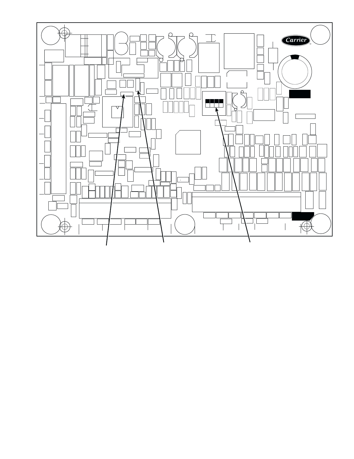
Board Addresses — The Main Base Board (MBB) has
a 3-position Instance jumper that must be set to ‘1.’ All other
boards have 4-position DIP switches. All switches are set to
‘On’ for all boards.
UNIT
30GTN,R
NOMINAL
TONS
SECTION A
UNIT 30GTN,R
SECTION B
UNIT 30GTN,R
040 40 — —
045 45 — —
050 50 — —
060 60 — —
070 70 — —
080 80 — —
090 90 — —
100 100 — —
110 110 — —
130 125 — —
150 145 — —
170 160 — —
190 180 — —
210 200 — —
230 220 150 080
245 230 150 090
255 240 150 100
270 260 170 100
290 280 190 110
315 300 210 110
330 325 170 170
360 350 190 190/170*
390 380 210 190
420 400 210 210
UNIT
30GUN,R
NOMINAL
TONS
SECTION A
UNIT 30GUN,R
SECTION B
UNIT 30GUN,R
040 26 — —
045 28 — —
050 34 — —
060 42 — —
070 48 — —
080 55 — —
090 59 — —
100 66 — —
110 72 — —
130 84 — —
150 99 — —
170 110 — —
190 122 — —
210 134 — —
230 154 150 080
245 158 150 090
255 165 150 100
270 176 170 100
290 193 190 110
315 206 210 110
330 219 170 170
360 243 190 190/170*
390 256 210 190
420 268 210 210
4
Control Module Communication
RED LED — Proper operation of the control boards can be
visually checked by looking at the red status LEDs (light-
emitting diodes). When operating correctly, the red status
LEDs should be blinking in unison at a rate of once every
2 seconds. If the red LEDs are not blinking in unison, verify
that correct power is being supplied to all modules. Be sure that
the Main Base Board (MBB) is supplied with the current soft-
ware. If necessary, reload current software. If the problem still
persists, replace the MBB. A red LED that is lit continuously or
blinking at a rate of once per second or faster indicates that the
board should be replaced.
GREEN LED — The MBB has one green LED. The Local
Equipment Network (LEN) LED should always be blinking
whenever power is on. All other boards have a LEN LED
which should be blinking whenever power is on. Check LEN
connections for potential communication errors at the board J3
and/or J4 connectors. Communication between modules is ac-
complished by a 3-wire sensor bus. These 3 wires run in paral-
lel from module to module. The J4 connector on the MBB pro-
vides both power and communication directly to the marquee
display only.
YELLOW LED — The MBB has one yellow LED. The
Carrier Comfort Network (CCN) LED will blink during times
of network communication.
Carrier Comfort Network (CCN) Interface —
The 30GTN,R chiller units can be connected to the CCN if
desired. The communication bus wiring is a shielded,
3-conductor cable with drain wire and is supplied and installed
in the field. The system elements are connected to the commu-
nication bus in a daisy chain arrangement. The positive pin of
each system element communication connector must be wired
to the positive pins of the system elements on either side of it.
This is also required for the negative and signal ground pins of
each system element. Wiring connections for CCN should be
made at TB3. Consult the CCN Contractor’s Manual for fur-
ther information.
NOTE: Conductors and drain wire must be 20 AWG (Amer-
ican Wire Gage) minimum stranded, tinned copper. Individual
conductors must be insulated with PVC, PVC/nylon, vinyl,
Teflon, or polyethylene. An aluminum/polyester 100% foil
shield and an outer jacket of PVC, PVC/nylon, chrome vinyl,
or Teflon with a minimum operating temperature range of
–20 C to 60 C is required. Wire manufactured by Alpha (2413
or 5463), American (A22503), Belden (8772), or Columbia
(02525) meets the above mentioned requirements.
It is important when connecting to a CCN communication
bus that a color coding scheme be used for the entire network
to simplify the installation. It is recommended that red be used
for the signal positive, black for the signal negative, and white
for the signal ground. Use a similar scheme for cables contain-
ing different colored wires.
At each system element, the shields of its communication
bus cables must be tied together. If the communication bus is
entirely within one building, the resulting continuous shield
must be connected to a ground at one point only. If the commu-
nication bus cable exits from one building and enters another,
the shields must be connected to grounds at the lightning sup-
pressor in each building where the cable enters or exits the
building (one point per building only). To connect the unit to
the network:
1. Turn off power to the control box.
2. Cut the CCN wire and strip the ends of the red (+), white
(ground), and black (–) conductors. (Substitute appropri-
ate colors for different colored cables.)
3. Connect the red wire to (+) terminal on TB3 of the plug,
the white wire to COM terminal, and the black wire to the
(–) terminal.
4. The RJ14 CCN connector on TB3 can also be used, but is
only intended for temporary connection (for example, a
laptop computer running Service Tool).
Table 2 — Thermistor Designations
LEGEND
IMPORTANT: A shorted CCN bus cable will prevent
some routines from running and may prevent the unit
from starting. If abnormal conditions occur, unplug the
connector. If conditions return to normal, check the
CCN connector and cable. Run new cable if necessary.
A short in one section of the bus can cause problems
with all system elements on the bus.
THERMISTOR
NO.
PIN
CONNECTION
POINT
THERMISTOR INPUT
T1 J8-13,14 (MBB) Cooler Leaving Fluid
T2 J8-11,12 (MBB) Cooler Entering Fluid
T3 J8-21,22 (MBB) Saturated Condensing
Te m p e r a t u re, C k t A
T4 J8-15,16 (MBB) Saturated Condensing
Te m p e r a t u re, C k t B
T5 J8-24,25 (MBB) Cooler Suction Temperature,
Ckt A (EXV Only)
T6 J8-18,19 (MBB) Cooler Suction Temperature,
Ckt B (EXV Only)
T7 J5-11,12 (EXV) Compressor Suction Gas
Temperature, Ckt A (EXV Only)
T8 J5-9,10 (EXV) Compressor Suction Gas
Temperature, Ckt B (EXV Only)
T9
J8-7,8 (MBB) Outdoor-Air Temperature
Sensor or Dual Chiller LWT
Sensors (Accessory)
T10 J8-5,6 (MBB) Remote Space Temperature
Sensor (Accessory)
EXV — Electronic Expansion Valve
MBB — Main Base Board
5
Table 3 — Status Switches
LEGEND *The OPS can also be added as an accessory.
†The CPCS can be added as an accessory.
Table 4 — Output Relay
LEGEND
OFM — Outdoor-Fan Motor
*And associated modular units.
†Field-installed accessory unloader.
LEGEND FOR FIG. 1-4
STATUS SWITCH
PIN
CONNECTION
POINT
040-060 (50 Hz)
040-070 (60 Hz)
070
(50 Hz)
080, 230B
090-110,
245B-315B
130
(60 Hz)
130 (50 Hz)
150, 230A-
255A
170,190,
270A,290A,
330A/B,
360A/B, 390B
210, 315A,
390A,
420A/B
Oil Pressure, Ckt B J7-1, 2 (MBB) Not Used* OPSB OPSB OPSB OPSB OPSB OPSB
Oil Pressure, Ckt A J7-3, 4 (MBB) Not Used* OPSA OPSA OPSA OPSA OPSA OPSA
Remote On/Off TB5-13, 14 Field-Installed Relay Closure
Compressor Fault
Signal, B3 J5-8, 12 (CXB) Not Used Not Used Not Used Not Used Not Used CR-B3 CR-B3
Compressor Fault
Signal, B2 J9-2, 12 (MBB) Not Used Not Used CPCS-B2 CR-B2 CR-B2 CR-B2 CR-B2
Compressor Fault
Signal, B1 J9-8, 12 (MBB) CR/CPCS-B1† CPCS-B1 CPCS-B1 CR-B1 CR-B1 CR-B1 CR-B1
Compressor Fault
Signal, A4 J5-5, 12 (CXB) Not Used Not Used Not Used Not Used Not Used Not Used CR-A4
Compressor Fault
Signal, A3 J5-11, 12 (CXB) Not Used Not Used Not Used Not Used CR-A3 CR-A3 CR-A3
Compressor Fault
Signal, A2 J9-5, 12 (MBB) Not Used CPCS-A2 CPCS-A2 CR-A2 CR-A2 CR-A2 CR-A2
Compressor Fault
Signal, A1 J9-11, 12 (MBB) CR/CPCS-A1† CPCS-A1 CPCS-A1 CR-A1 CR-A1 CR-A1 CR-A1
CPCS — Compressor Protection Control System
CR — Control Relay
CXB — Compressor Expansion Board
MBB — Main Base Board
OPS — Oil Pressure Switch, Circuit A or B
RELAY
NO. DESCRIPTION
K1(MBB)
Energize Compressor A1 and OFM1 (040-110*)
Energize Liquid Line Solenoid Valve for Ckt A (if used)
(040-110*)
Energize Compressor A1, OFM5, and OFM7 (130-210*)
K2 (MBB)
Energize Compressor B1 and OFM2 (040-110*)
Energize Liquid Line Solenoid Valve for Ckt B (if used)
(040-110*)
Energize Compressor B1, OFM6, and OFM8 (130-210*)
K3 (MBB) Energize Unloader A1 (040-170*)
No Action (190-210*)
K4 (MBB) Energize Unloader B1 (040-070†, 080-170*)
No Action (190,210*)
K5 (MBB) No Action (040-060, 50 Hz; 040-070, 60 Hz)
Energize Compressor A2 (070, 50 Hz; 080-210*)
K6 (MBB) No Action (040-080*)
Energize Compressor B2 (090-210*)
K7 (MBB) Alarm
K8 (MBB) Cooler Pump
K9 (MBB)
Energize First Stage of Condenser Fans:
040-050 —OFM3
060-110* — OFM3, OFM4
130 (60 Hz) — OFM1,OFM2
Energize First Stage of Ckt A Condenser Fans:
130 (50 Hz), 150,170* — OFM1
190,210* —OFM1,OFM11
K10 (MBB)
Energize Second Stage of Condenser Fans:
040-050 — OFM4
060-090* — OFM5, OFM6
100,110* — OFM5,OFM6,OFM7,OFM8
130 (60 Hz) — OFM3,OFM4,OFM9,OFM10
Energize First Stage of Ckt B Condenser Fans:
130 (50 Hz), 150,170* — OFM2
190,210* — OFM2,OFM12
K11 (MBB) Hot Gas Bypass
K1 (CXB) No Action (040-110*; 130, 60 Hz)
Energize Compressor A3 (130, 50 Hz; 150-210*)
K2 (CXB) No Action (040-150*)
Energize Compressor B3 (170-210*)
K3 (CXB) Energize Compressor A4 (210*)
Energize Accessory Unloader A2 (080-110*)
K4 (CXB) Energize Accessory Unloader B2 (080-110*)
K5 (CXB) Energize Second Stage of Ckt A Condenser Fans:
130 (50 Hz), 150-210* — OFM3,OFM9
K6 (CXB) Energize Second Stage of Ckt B Condenser Fans:
130 (50 Hz), 150-210* — OFM4,OFM10
C—
Compressor Contactor
CB — Circuit Breaker
CCN — Carrier Comfort Network
CGF — Compressor Ground Fault
CHT — Cooler Heater Thermostat
CKT — Circuit
CLHR — Cooler Heater Relay
CPCS — Compressor Protection and Control System
CWFS — Chilled Water Flow Switch
CWPI — Chilled Water Pump Interlock
CR — Control Relay
CXB — Compressor Expansion Board
EQUIP GND — Equipment Ground
FB — Fuse Block
FC — Fan Contactor
FCB — Fan Circuit Breaker
FIOP — Factory-Installed Option Package
EMM — Energy Management Module
EXV — Electronic Expansion Valve
FCB — Fan Circuit Breaker
HPS — High-Pressure Switch
LCS — Loss-of-Charge Switch
LEN — Local Equipment Network
MBB — Main Base Board
NEC — National Electrical Code
OAT — Outdoor-Air Temperature
OPS — Oil Pressure Switch
PL — Plug
PW — Part Wind
SN — Sensor (Toroid)
SPT — Space Temperature
TRAN — Transformer
SW — Switch
TB — Terminal Block
TDR — Time Delay Relay
TXV — Thermostatic Expansion Valve
UL — Unloader
XL — Across-the-Line
6
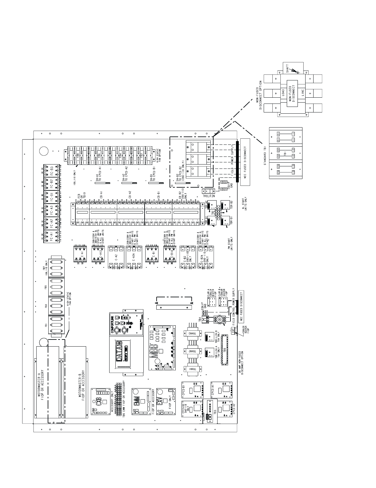
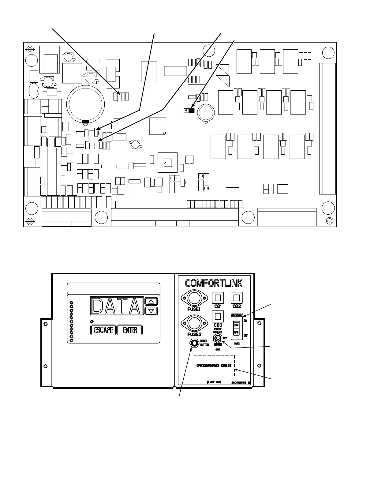
Fig. 1 — Typical Control Box (080-110 and Associated Modular Units Shown)
7
CCN
LEN
DATA
COMMUNICATION
PORT
Fig. 2 — 24 V Control Schematic, Unit Sizes 040-070
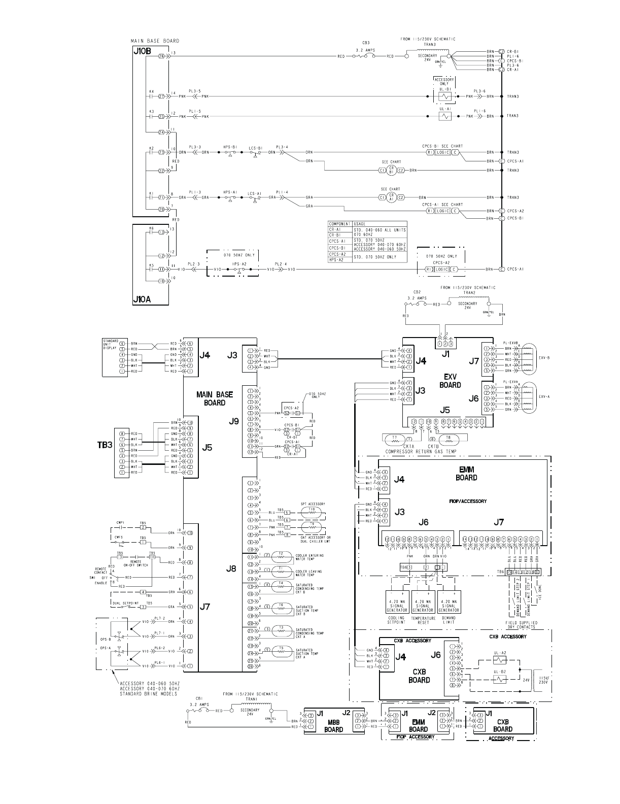
8
Fig. 3 — 24 V Control Schematic, Unit Sizes 080-110, 230B-315B
CCN
LEN
DATA
COMMUNICATION
PORT
/
Fig. 3 — 24 V Control Schematic, Unit Sizes 080-110, 230B-315B
9
CCN
LEN
DATA
COMMUNICATION
PORT
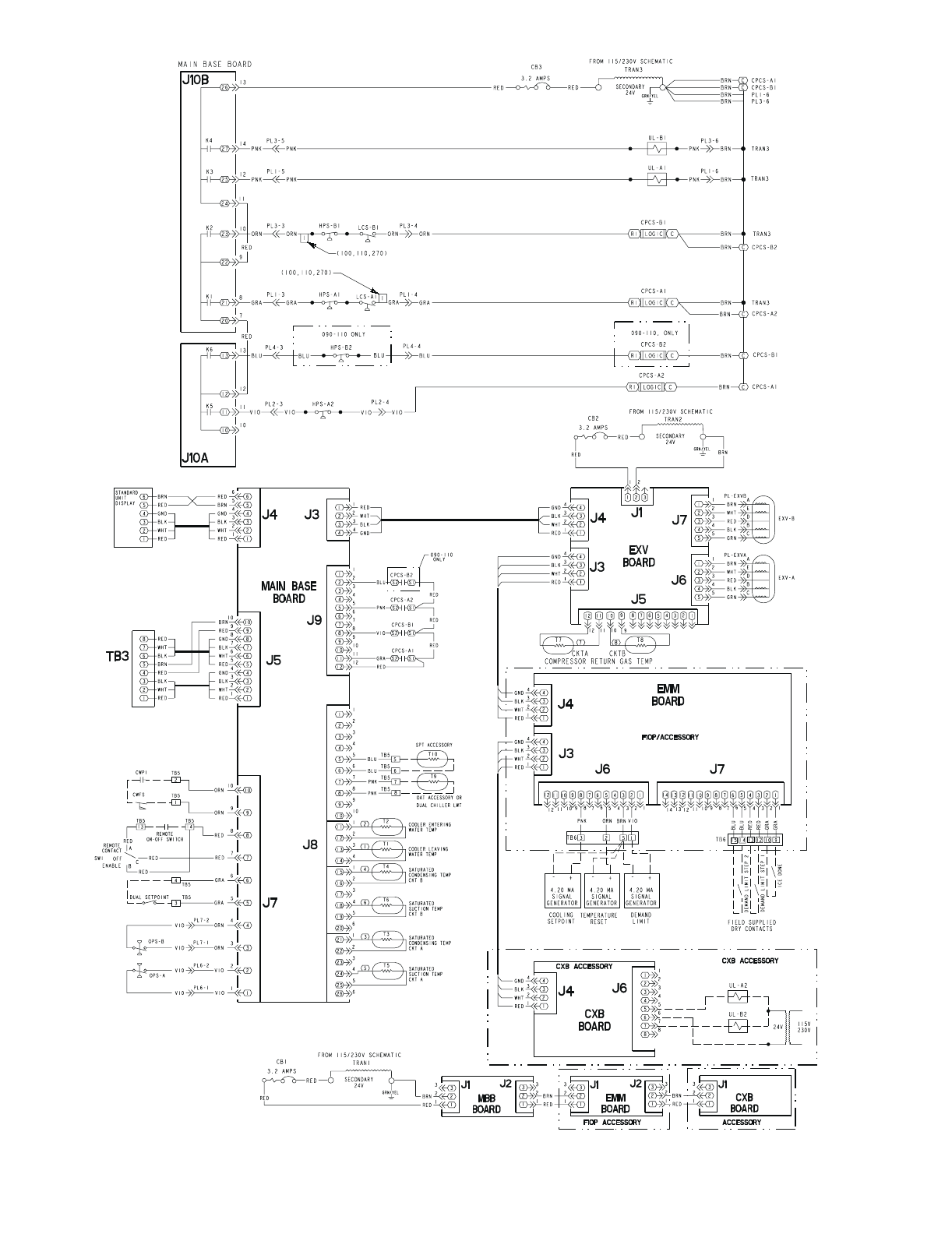
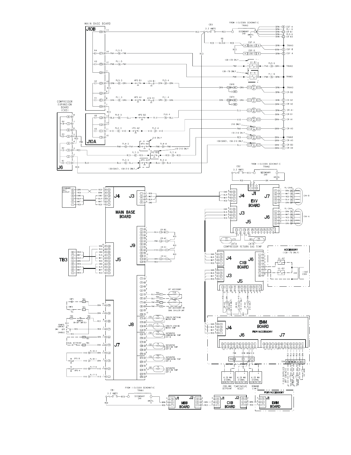
Fig. 4 — 24 V Control Schematic, Unit Sizes 130-210, 230A-315A, 330A/B-420A/B
10
CEPL130346-01
STATUS
LEN
J1 J2
J4 J3
J5
J6
J7 J8 J9
J10
CCN
RED LED - STATUS GREEN LED -
LEN (LOCAL EQUIPMENT NETWORK)
YELLOW LED -
CCN (CARRIER COMFORT NETWORK)
INSTANCE JUMPER
EMERGENCY ON/OFF
SWITCH
ENABLE/OFF/REMOTE
CONTACT SWITCH
GFI-CONVENIENCE
OUTLET ACCESSORY
ON 208/230V 460 AND
575V ONLY
RESET BUTTON
(SIZES 130-210 AND
ASSOCIATED MODULES ONLY)
Fig. 5 — Main Base Board
Fig. 6 — Enable/Off/Remote Contact Switch, Emergency On/Off Switch,
and Reset Button Locations
11
OPERATING DATA
Sensors — The electronic control uses 4 to 10 thermistors
to sense temperatures for controlling chiller operation. See
Table 2. These sensors are outlined below. See Fig. 7-10 for
thermistor locations. Thermistors T1-T9 are 5 kΩ at 77 F
(25 C). Thermistors T1, T2, T3-T6 and T7-T9 have different
temperature versus resistance and voltage drop performance.
Thermistor T10 is 10 kΩ at 77 F (25 C) and has a different tem-
perature vs resistance and voltage drop performance. See Ther-
mistors section on page 59 for temperature-resistance-voltage
drop characteristics.
T1 — COOLER LEAVING FLUID SENSOR — This ther-
mistor is located in the leaving fluid nozzle. The thermistor
probe is inserted into a friction-fit well.
T2 — COOLER ENTERING FLUID SENSOR — This
thermistor is located in the cooler shell in the first baffle space
in close proximity to the cooler tube bundle.
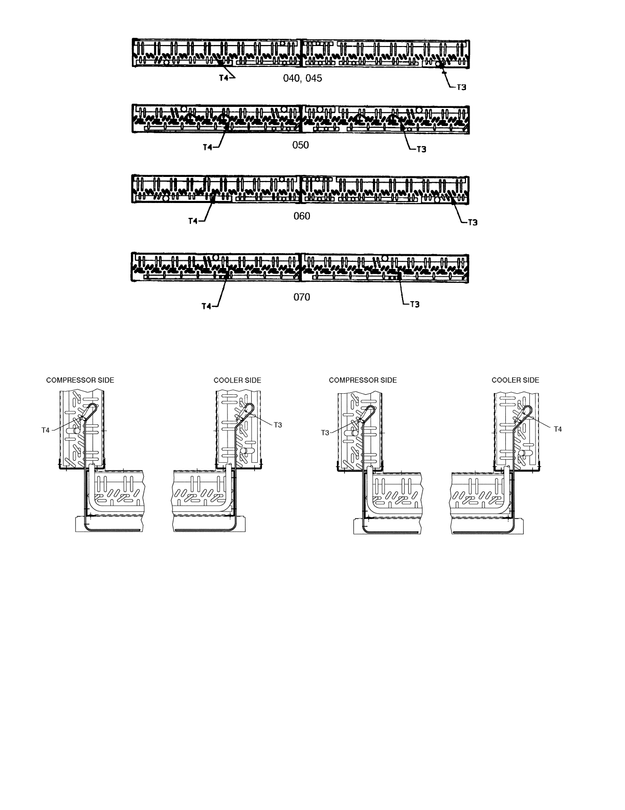
T3, T4 — SATURATED CONDENSING TEMPERATURE
SENSORS — These 2 thermistors are clamped to the outside
of a return bend of the condenser coils.
T5, T6 — COOLER SUCTION TEMPERATURE SEN-
SORS — These thermistors are located next to the refrigerant
inlet in the cooler head, and are inserted into a friction-fit well.
The sensor well is located directly in the refrigerant path. These
thermistors are not used on units with TXVs.
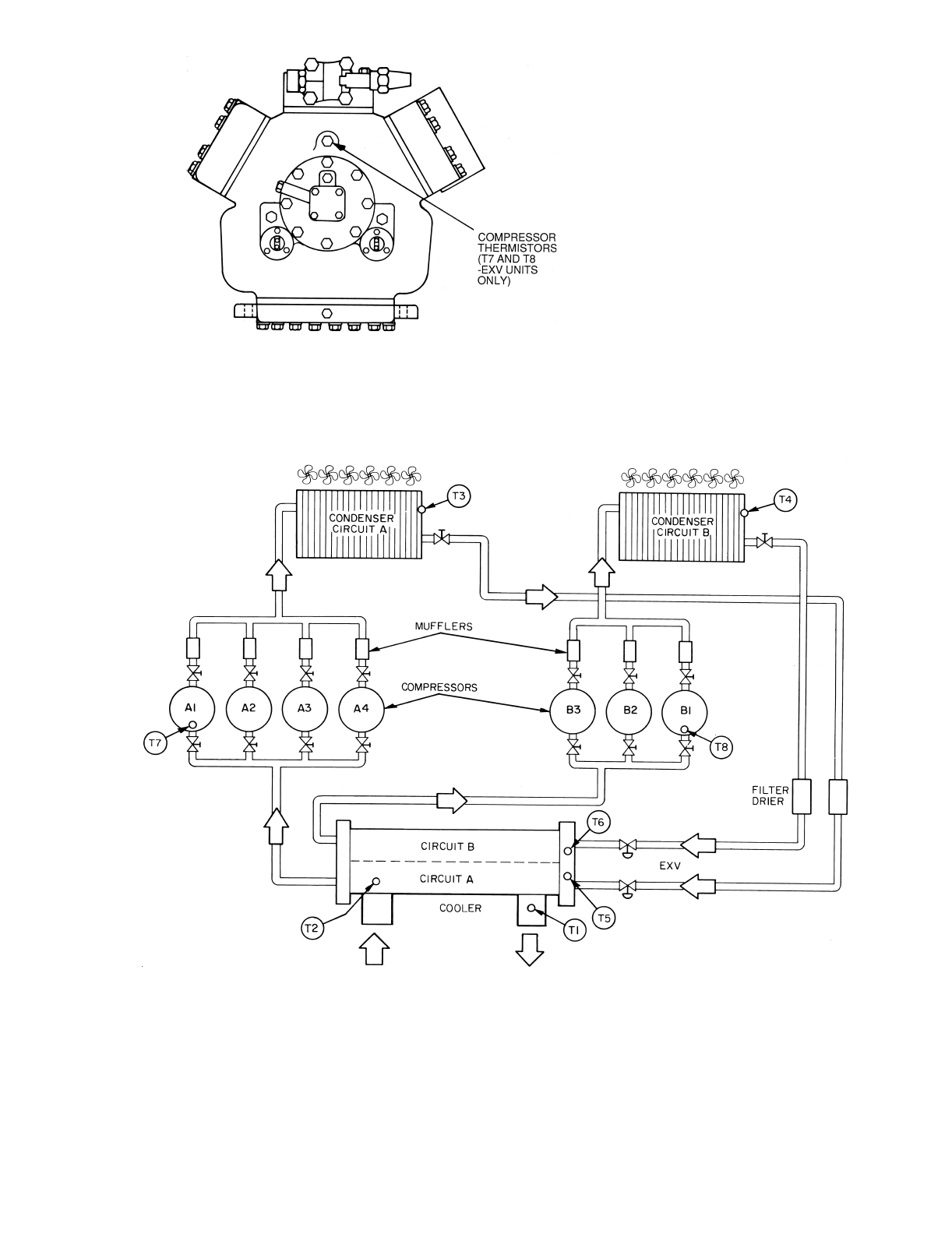
T7, T8 — COMPRESSOR SUCTION GAS TEMPERA-
TURE SENSORS — These thermistors are located in the lead
compressor in each circuit in a suction passage after the refrig-
erant has passed over the motor and is about to enter the cylin-
ders. These thermistors are inserted into friction-fit wells. The
sensor wells are located directly in the refrigerant path. These
thermistors are not used on units with TXVs.
T9 — OUTDOOR-AIR TEMPERATURE SENSOR —
Sensor T9 is an accessory sensor that is remotely mounted and
used for outdoor-air temperature reset.
MIN. 6” OF 22 AWG WIRES
WITH ENDS STRIPPED BACK
.25” ±1/8”
1/2” PVC SHIELD
1/2 NPT MALE
THREADED ADAPTER
3/16” DIA.
THERMOWELL (S.S.)
REF.
.83 D
(21.1)
REF.
1.81
(46.0)
REF.
5.75
(146.1
LEGEND
*And associated modular units.
AWG — American Wire Gage
EXV — Electronic Wire Gage
Fig. 7 — Cooler Thermistor Locations and Accessory Outdoor-Air Temperature Sensor Detail
040-110*
130-210*
12
*When thermistor is viewed from perspective where the compressor is on the left and the cooler is on the right.
Fig. 8 — Thermistor T3 and T4 Locations
040-070
080-110 AND ASSOCIATED MODULAR UNITS* 130-210 AND ASSOCIATED MODULAR UNITS*
13
Fig. 9 — Compressor Thermistor Locations (T7 and T8)
LEGEND
EXV — Electronic Expansion Valve
Fig. 10 — Typical Thermistor Location (30GTN,R and 30GUN,R 210, 315A, 390A, 420A/B Shown)
14
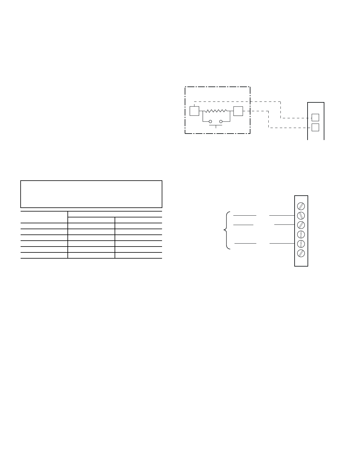
T10 — REMOTE SPACE TEMPERATURE SENSOR —
Sensor T10 (part no. HH51BX006) is an accessory sensor that
is remotely mounted in the controlled space and used for space
temperature reset. The sensor should be installed as a
wall-mounted thermostat would be (in the conditioned space
where it will not be subjected to either a cooling or heating
source or direct exposure to sunlight, and 4 to 5 ft above the
floor). The push button override button is not supported by the
ComfortLink™ Controls.
Space temperature sensor wires are to be connected to ter-
minals in the unit main control box. The space temperature
sensor includes a terminal block (SEN) and a RJ11 female con-
nector. The RJ11 connector is used to tap into the Carrier Com-
fort Network (CCN) at the sensor.
To connect the space temperature sensor (Fig. 11):
1. Using a 20 AWG (American Wire Gage) twisted pair
conductor cable rated for the application, connect 1
wire of the twisted pair to one SEN terminal and con-
nect the other wire to the other SEN terminal located
under the cover of the space temperature sensor.
2. Connect the other ends of the wires to terminals 5 and 6
on TB5 located in the unit control box.
Units on the CCN can be monitored from the space at the
sensor through the RJ11 connector, if desired. To wire the RJ11
connector into the CCN (Fig. 12):
1. Cut the CCN wire and strip ends of the red (+), white
(ground), and black (–) conductors. (If another wire
color scheme is used, strip ends of appropriate wires.)
2. Insert and secure the red (+) wire to terminal 5 of the
space temperature sensor terminal block.
3. Insert and secure the white (ground) wire to terminal 4 of
the space temperature sensor.
4. Insert and secure the black (–) wire to terminal 2 of the
space temperature sensor.
5. Connect the other end of the communication bus cable to
the remainder of the CCN communication bus.
IMPORTANT: The cable selected for the RJ11 connec-
tor wiring MUST be identical to the CCN communica-
tion bus wire used for the entire network. Refer to table
below for acceptable wiring.
MANUFACTURER PART NO.
Regular Wiring Plenum Wiring
Alpha 1895 —
American A21451 A48301
Belden 8205 884421
Columbia D6451 —
Manhattan M13402 M64430
Quabik 6130 —
SPT (T10) PART NO. HH51BX006
SENSOR
SEN SEN TB5
5
6
T-55 SPACE
SENSOR
CCN+
CCN GND
CCN-
TO CCN
TERMINALS
ON TB3
AT UNIT
1
2
3
4
5
6
Fig. 11 — Typical Space Temperature
Sensor Wiring
Fig. 12 — CCN Communications Bus Wiring
to Optional Space Sensor RJ11 Connector
15
Thermostatic Expansion Valves (TXV) — Model
30GTN,R and 30GUN,R 040-110 units are available from the
factory with conventional TXVs with liquid line solenoids. The
liquid line solenoid valves are not intended to be a mechanical
shut-off. When service is required, use the liquid line service
valve to pump down the system.
NOTE: This option is not available for modular units.
The TXV is set at the factory to maintain approximately 8 to
12° F (4.4 to 6.7° C) suction superheat leaving the cooler by
metering the proper amount of refrigerant into the cooler. All
TXVs are adjustable, but should not be adjusted unless abso-
lutely necessary. When TXV is used, thermistors T5, T6, T7,
and T8 are not required.
The TXV is designed to limit the cooler saturated suction
temperature to 55 F (12.8 C). This makes it possible for unit to
start at high cooler fluid temperatures without overloading the
compressor.
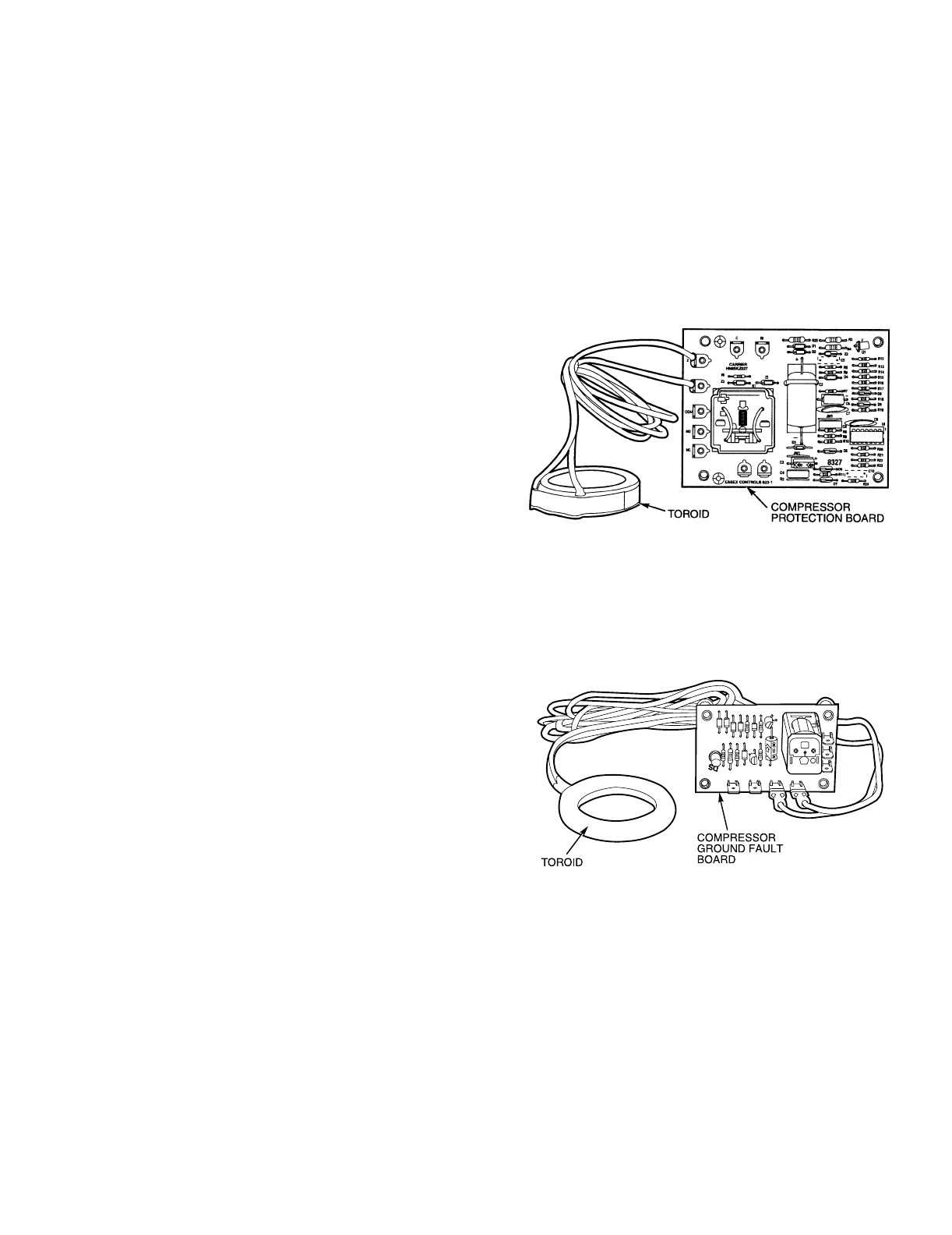
Compressor Protection Control System (CPCS
[CPCS — Standard on Sizes 080-110 and
Optional on Sizes 040-070]) or Control Relay
(CR) — 30GTN,R and 30GUN,R 040-110 — Each
compressor has its own CPCS module or CR. See Fig. 13 for
CPCS module. The CPCS or CR is used to control and protect
the compressors and crankcase heaters. The CPCS and CR pro-
vide the following functions:
• compressor contactor control/crankcase heater
• crankcase heater control
• compressor ground current protection (CPCS only)
• status communication to processor board
• high-pressure protection
One large relay is located on the CPCS board. This relay
controls the crankcase heater and compressor contactor, and
also provides a set of signal contacts that the microprocessor
monitors to determine the operating status of the compressor. If
the processor board determines that the compressor is not oper-
ating properly through the signal contacts, it will lock the com-
pressor off by deenergizing the proper 24-v control relay on the
relay board. The CPCS board contains logic that can detect if
the current-to-ground of any compressor winding exceeds
2.5 amps. If this condition occurs, the CPCS shuts down the
compressor.
A high-pressure switch is wired in series between the MBB
and the CR or CPCS. On compressor A1 and B1 a loss-of-
charge switch is also wired in series with the high-pressure
switch. If the high-pressure switch opens during operation of a
compressor, the compressor will be stopped, the failure will be
detected through the signal contacts, and the compressor will
be locked off. If the lead compressor in either circuit is shut
down by the high-pressure switch, loss-of-charge switch,
ground current protector, or oil safety switch, all compressors
in that circuit are shut down.
NOTE: The CR operates the same as the CPCS, except the
ground current circuit protection is not provided.
Compressor Ground Current Protection
Board (CGF) and Control Relay (CR) — The
30GTN,R and 30GUN,R 130-210, and associated modular
units (see Table 1) contain one compressor ground current pro-
tection board (CGF) (see Fig. 14) for each refrigeration circuit.
The CGF contains logic that can detect if the current-to-ground
of any compressor winding exceeds 2.5 amps. If this occurs,
the lead compressor in that circuit is shut down along with oth-
er compressors in that circuit.
A high-pressure switch is wired in series between the MBB
and the CR. On compressor A1 and B1 a loss-of-charge switch
is also wired in series with the high-pressure switch. The lead
compressor in each circuit also has the CGF contacts described
above. If any of these switches open during operation of a com-
pressor, the CR relay is deenergized, stopping the compressor
and signaling the processor at the MBB-J9 inputs to lock out
the compressor. If the lead compressor in either circuit is shut
down by high-pressure switch, compressor ground fault, oil
pressure switch, or the loss-of-charge switch, all compressors
in that circuit are also shut down.
Fig. 13 — Compressor Protection Control
System Module — Sizes 040-110
Fig. 14 — Compressor Ground Fault Module
— Sizes 130-210
16
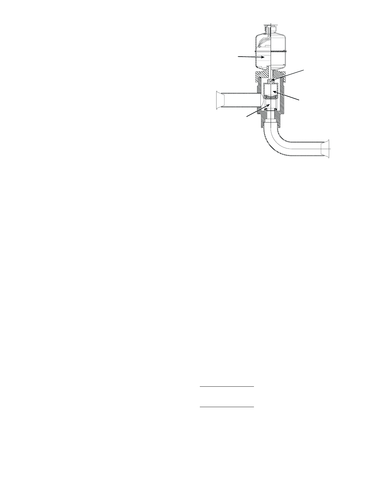
Electronic Expansion Valve (EXV) (See
Fig. 15) — Standard units are equipped with a bottom seal
EXV. This device eliminates the use of the liquid line solenoid
pumpdown at unit shutdown. An O-ring has been added to bot-
tom of orifice assembly to complete a seal in the valve on shut-
down. This is not a mechanical shut-off. When service is
required, use the liquid line service valve to pump down the
system.
High pressure refrigerant enters bottom of valve where it
passes through a group of machined slots in side of orifice as-
sembly. As refrigerant passes through the orifice, it drops in
pressure. To control flow of refrigerant, the sleeve slides up and
down along orifice assembly, modulating the size of orifice.
The sleeve is moved by a linear stepper motor that moves in in-
crements controlled directly by the processor. As stepper motor
rotates, the motion is translated into linear movement of lead
screw. There are 1500 discrete steps with this combination. The
valve orifice begins to be exposed at 320 steps. Since there is
not a tight seal with the orifice and the sleeve, the minimum po-
sition for operation is 120 steps.
Two thermistors are used to determine suction superheat.
One thermistor is located in the cooler and the other is located
in the cylinder end of the compressor after refrigerant has
passed over the motor. The difference between the 2 ther-
mistors is the suction superheat. These machines are set up to
provide approximately 5 to 7 F (2.8 to 3.9 C) superheat leaving
the cooler. Motor cooling accounts for approximately 22 F
(12.2 C) on 30GTN,R units and 16 F (8.9 C) on 30GUN,R
units, resulting in a superheat entering compressor cylinders of
approximately 29 F (16.1 C) for 30GTN,R units and 23 F
(12.8 C) for 30GUN,R units.
Because the valves are controlled by the EXV module, it is
possible to track the position of the valve. Valve position can be
used to control head pressure and system refrigerant charge.
During initial start-up, the EXV module will drive each
valve fully closed. After initialization period, valve position is
controlled by the EXV module and the MBB.
The EXV is used to limit the maximum cooler saturated
suction temperature to 55 F (12.8 C). This makes it possible for
the chiller to start at high cooler fluid temperatures without
overloading the compressor.
Energy Management Module (Fig. 16) — This
factory-installed option or field-installed accessory is used for
the following types of temperature reset, demand limit, and/or
ice features:
•4 to 20 mA leaving fluid temperature reset (requires
field-supplied 4 to 20 mA generator)
•4 to 20 mA cooling set point reset (requires field-
supplied 4 to 20 mA generator)
•Discrete inputs for 2-step demand limit (requires field-
supplied dry contacts capable of handling a 5 vdc, 1 to
20 mA load)
•4 to 20 mA demand limit (requires field-supplied 4 to
20 mA generator)
•Discrete input for Ice Done switch (requires field-
supplied dry contacts capable of handling a 5 vdc, 1 to
20 mA load)
See Demand Limit and Temperature Reset sections on
pages 46 and 43 for further details.
Capacity Control — The control system cycles com-
pressors, unloaders, and hot gas bypass solenoids to maintain
the user-configured leaving chilled fluid temperature set point.
Entering fluid temperature is used by the Main Base Board
(MBB) to determine the temperature drop across the cooler and
is used in determining the optimum time to add or subtract ca-
pacity stages. The chilled fluid temperature set point can be au-
tomatically reset by the return temperature reset or space and
outdoor-air temperature reset features. It can also be reset from
an external 4 to 20 mA signal (requires Energy Management
Module FIOP/accessory).
With the automatic lead-lag feature in the unit, the control
determines which circuit will start first, A or B. At the first call
for cooling, the lead compressor crankcase heater will be deen-
ergized, a condenser fan will start, and the compressor will start
unloaded.
NOTE: The automatic lead-lag feature is only operative when
an even number of unloaders is present. The 040-070 units
require an accessory unloader to be installed on the B1 com-
pressor for the lead-lag feature to be in effect.
If the circuit has been off for 15 minutes, and the unit is a
TXV unit, liquid line solenoid will remain closed during start-
up of each circuit for 15 seconds while the cooler and suction
lines are purged of any liquid refrigerant. For units with EXVs,
the lead compressor will be signaled to start. The EXV will re-
main at minimum position for 10 seconds before it is allowed
to modulate.
After the purge period, the EXV will begin to meter the re-
frigerant, or the liquid line solenoid will open allowing the
TXV to meter the refrigerant to the cooler. If the off-time is less
than 15 minutes, the EXV will be opened as soon as the com-
pressor starts.
The EXVs will open gradually to provide a controlled start-
up to prevent liquid flood-back to the compressor. During start-
up, the oil pressure switch is bypassed for 2 minutes to allow
for the transient changes during start-up. As additional stages
of compression are required, the processor control will add
them. See Tables 5A and 5B.
If a circuit is to be stopped, the control will first start to close
the EXV or close the liquid line solenoid valve.
For units with TXVs, the lag compressor(s) will be shut
down and the lead compressor will continue to operate for
10 seconds to purge the cooler of any refrigerant.
For units with EXVs, the lag compressor(s) will be shut
down and the lead compressor will continue to run. After the
lag compressor(s) has shut down, the EXV is signaled to close.
The lead compressor will remain on for 10 seconds after the
EXV is closed.
During both algorithms (TXV and EXV), all diagnostic
conditions will be honored. If a safety trip or alarm condition is
detected before pumpdown is complete, the circuit will be shut
down.
STEPPER
MOTOR (12 VDC)
ORIFICE ASSEMBLY
(INSIDE PISTON SLEEVE)
PISTON SLEEVE
LEAD SCREW
Fig. 15 — Electronic Expansion Valve (EXV)
17
The capacity control algorithm runs every 30 seconds. The
algorithm attempts to maintain the leaving chilled water tem-
perature at the control point. Each time it runs, the control reads
the entering and leaving fluid temperatures. The control deter-
mines the rate at which conditions are changing and calculates
2 variables based on these conditions. Next, a capacity ratio is
calculated using the 2 variables to determine whether or not to
make any changes to the current stages of capacity. This ratio
value ranges from –100 to + 100%. If the next stage of capacity
is a compressor, the control starts (stops) a compressor when
the ratio reaches +100% (–100%). If the next stage of capacity
is an unloader, the control deenergizes (energizes) an unloader
when the ratio reaches +60% (–60%). Unloaders are allowed to
cycle faster than compressors, to minimize the number of starts
and stops on each compressor. A delay of 90 seconds occurs af-
ter each capacity step change.
CEBD430351-0396-01C
TEST 1
CEPL130351-01
PWR
TEST 2
J1 J2
J4 J3
J5
J6
J7
LEN
STATUS
RED LED - STATUS GREEN LED -
LEN (LOCAL EQUIPMENT NETWORK) ADDRESS
DIP SWITCH
Fig. 16 — Energy Management Module

18
Table 5A — Part Load Data Percent Displacement, Standard Units
*Unloaded compressor.
NOTE: These capacity control steps may vary due to lag compressor sequencing.
UNIT
30GTN,R
30GUN,R
CONTROL
STEPS
LOADING SEQUENCE A LOADING SEQUENCE B
% Displacement
(Approx) Compressors % Displacement
(Approx) Compressors
040 (60 Hz)
125A1*——
250A1——
375A1*, B1——
4 100 A1,B1 ——
040 (50 Hz)
045 (60 Hz)
124A1*——
247A1——
376A1*,B1——
4 100 A1,B1 ——
045 (50 Hz)
050 (60 Hz)
131A1*——
244A1——
387A1*,B1——
4 100 A1,B1 ——
050 (50 Hz)
060 (60 Hz)
128A1*——
242A1——
387A1*,B1——
4 100 A1,B1 ——
060 (50 Hz)
070 (60 Hz)
133A1*——
250A1——
383A1*,B1——
4 100 A1,B1 ——
070 (50 Hz)
119A1*——
227A1——
365A1*,B1——
473A1,B1——
5 92 A1*,A2,B1 ——
6 100 A1,A2,B1 ——
080, 230B (60 Hz)
1 22 A1* 30 B1*
234A144B1
3 52 A1*,B1* 52 A1*,B1*
4 67 A1*,B1 63 A1,B1*
5 78 A1,B1 78 A1,B1
6 89 A1*,A2,B1 85 A1,A2,B1*
7 100 A1,A2,B1 100 A1,A2,B1
080, 230B (50 Hz)
1 17 A1* 25 B1*
225A138B1
3 42 A1*,B1* 42 A1*,B1*
4 54 A1*,B1 50 A1, B1*
5 62 A1,B1 62 A1,B1
6 79 A1*,A2,B1* 79 A1*,A2,B1*
7 92 A1*,A2,B1 88 A1,A2,B1*
8 100 A1,A2,B1 100 A1,A2,B1
090, 245B (60 Hz)
1 18 A1* 18 B1*
227A127B1
3 35 A1*,B1* 35 A1*,B1*
4 44 A1*,B1 44 A1,B1
5 53 A1,B1 53 A1,B1
6 56 A1*,A2,B1* 62 A1*,B1*,B2
7 65 A1*,A2,B1 71 A1,B1*,B2
8 74 A1,A2,B1 80 A1,B1,B2
9 82 A1*,A2,B1*,B2 82 A1*,A2,B1*,B2
10 91 A1*,A2,B1,B2 91 A1,A2,B1*,B2
11 100 A1,A2,B1,B2 100 A1,A2,B1,B2
090, 245B (50 Hz)
114A114B1*
221A121B1
3 29 A1*,B1* 29 A1*,B1*
4 36 A1*,B1 36 A1,B1*
5 43 A1,B1 43 A1,B1
6 61 A1*,A2,B1* 53 A1*,B1*,B2
7 68 A1*,A2,B1 60 A1,B1*,B2
8 75 A1,A2,B1 67 A1,B1,B2
9 86 A1*,A2,B1*,B2 86 A1*,A2,B1*,B2
10 93 A1*,A2,B1,B2 93 A1,A2,B1*,B2
11 100 A1,A2,B1,B2 100 A1,A2,B1,B2
100, 255B,
270B (60 Hz)
1 16 A1* 16 A1*
223A123A1
3 31 A1*,B1* 31 A1*,B1*
4 39 A1*,B1 39 A1*,B1
5 46 A1,B1 46 A1,B1
6 58 A1*,A2,B1* 58 A1*,A2,B1*
7 66 A1*,A2,B1 66 A1*,A2,B1
8 73 A1,A2,B1 73 A1,A2,B1
9 85 A1*,A2,B1*,B2 85 A1*,A2,B1*,B2
10 92 A1*,A2,B1,B2 92 A1*,A2,B1,B2
11 100 A1,A2,B1,B2 100 A1,A2,B1,B2

19
Table 5A — Part Load Data Percent Displacement, Standard Units (cont)
*Unloaded compressor.
NOTE: These capacity control steps may vary due to lag compressor sequencing.
UNIT
30GTN,R
30GUN,R
CONTROL
STEPS
LOADING SEQUENCE A LOADING SEQUENCE B
% Displacement
(Approx) Compressors % Displacement
(Approx) Compressors
100, 255B
270B (50 Hz)
1 13 A1* 13 B1*
220A120B1
3 26 A1*,B1* 26 A1*,B1*
4 33 A1,B1 33 A1,B1
5 40 A1,B1 40 A1,B1
6 57 A1*,A2,B1* 57 A1*,B1*,B2
7 63 A1*,A2,B1 63 A1,B1*,B2
8 70 A1,A2,B1 70 A1,B1,B2
9 87 A1*,A2,B1*,B2 87 A1*,A2,B1*,B2
10 93 A1*,A2,B1,B2 93 A1,A2,B1*,B2
11 100 A1,A2,B1,B2 100 A1,A2,B1,B2
110, 290B,
315B (60 Hz)
1 14 A1* 14 B1*
221A121B1
3 29 A1*,B1* 29 A1*,B1*
4 36 A1*,B1 36 A1,B1*
5 43 A1,B 43 A1,B1
6 61 A1*,A2,B1* 53 A1*,B1*,B2
7 68 A1*,A2,B1 60 A1,B1*,B2
8 75 A1,A2,B1 67 A1,B1,B2
9 86 A1*,A2,B1*,B2 86 A1*,A2,B1*,B2
10 93 A1*,A2,B1,B2 93 A1,A2,B1*,B2
11 100 A1,A2,B1,B2 100 A1,A2,B1,B2
110, 290B,
315B (50 Hz)
1 17 A1* 17 B1*
225A125B1
3 33 A1*,B1* 33 A1*,B1*
4 42 A1*,B1 42 A1,B1*
5 50 A1,B1 50 A1,B1
6 58 A1*,A2,B1* 58 A1*,B1*,B2
7 67 A1*,A2,B1 67 A1,B1*,B2
8 75 A1,A2,B1 75 A1,B1,B2
9 83 A1*,A2,B1*,B2 83 A1*,A2,B1*,B2
10 92 A1*,A2,B1,B2 92 A1,A2,B1*,B2
11 100 A1,A2,B1,B2 100 A1,A2,B1,B2
130 (60 Hz)
1 14 A1* 14 B1*
221A121B1
3 28 A1*,B1* 28 A1*,B1*
4 35 A1*,B1 35 A1,B1*
5 42 A1,B1 42 B1,B1
6 58 A1*,A2,B1* 58 A1*,B1*,B2
7 64 A1*,A2,B1 64 A1,B1*,B2
8 71 A1,A2,B1 71 A1,G1,B2
9 87 A1*,A2,B1*,B2 87 A1*,A2,B1*,B2
10 93 A1*,A2,B1,B2 93 A1,A2,B1*,B2
11 100 A1,A2,B1,B2 100 A1,A2,B1,B2
130 (50 Hz)
1 10 A1* 16 B1*
214A125B1
3 26 A1*,B1* 26 A1*,B1*
4 35 A1*,B1 31 A1,B1*
5 39 A1,B1 39 A1,B1
6 44 A1*,A2,B1* 51 A1*,B1*,B2
7 53 A1*,A2,B1 56 A1,B1*,B2
8 57 A1,A2,B1 64 A1,B1,B2
9 69 A1*,A2,B1*,B2 69 A1*,A2,B1*,B2
10 78 A1*,A2,B1,B2 75 A1,A2,B1*,B2
11 82 A1,A2,B1,B2 82 A1,A2,B1,B2
12 87 A1*,A2,A3,B1*,B2 87 A1*,A2,A3,B1*,B2
13 96 A1*,A2,A3,B1,B2 91 A1,A2,A3,B1*,B2
14 100 A1,A2,A3,B1,B2 100 A1,A2,A3,B1,B2
150, 230A, 245A,
255A (60 Hz)
1 11 A1* 18 B1*
215A127B1
3 29 A1*,B1* 29 A1*,B1*
4 38 A1*,B1 33 A1,B1*
5 42 A1,B1 42 A1,B1
6 44 A1*,A2,B1* 55 A1*,B1*,B2
7 53 A1*,A2,B1 60 A1,B1*,B2
8 58 A1,A2,B1 69 A1,B1,B2
9 71 A1*,A2,B1*,B2 71 A1*,A2,B1*,B2
10 80 A1*,A2,B1,B2 75 A1,A2,B1*,B2
11 85 A1,A2,B1,B2 85 A1,A2,B1,B2
12 86 A1*,A2,A3,B1*,B2 86 A1*,A2,A3,1*,B2
13 95 A1*,A2,A3,B1,B2 91 A1,A2,A3,B1*,B2
14 100 A1,A2,A3,B1,B2 100 A1,A2,A3,B1,B2

20
Table 5A — Part Load Data Percent Displacement, Standard Units (cont)
*Unloaded compressor.
NOTE: These capacity control steps may vary due to lag compressor sequencing.
UNITT
30GTN,R
30GUN,R
CONTROL
STEPS
LOADING SEQUENCE A LOADING SEQUENCE B
% Displacement
(Approx) Compressors % Displacement
(Approx) Compressors
150, 230A, 245A,
255A (50 Hz)
1
2
3
4
5
6
7
8
9
10
11
12
13
14
13
20
26
33
40
46
53
60
66
73
80
86
93
100
A1*
A1
A1*,B1*
A1*,B1
A1,B1
A1*,A2,B1*
A1*,A2,B1
A1,A2,B1
A1*,A2,B1*,B2
A1*,A2,B1,B2
A1,A2,B1,B2
A1*,A2,A3,B1*,B2
A1*,A2,A3,B1,B2
A1,A2,A3,B1,B2
13
20
26
33
40
46
53
60
66
73
80
86
93
100
B1*
B1
A1*,B1*
A1,B1*
A1,B1
A1*,B1*,B2
A1,B1*,B2
A1,B1,B2
A1*,A2,B1*,B2
A1,A2,B1*,B2
A1,A2,B1,B2
A1*,A2,A3,B1*,B2
A1,A2,A3,B1*,B2
A1,A2,A3,B1,B2
170, 270A,
330A/B (60 Hz)
1
2
3
4
5
6
7
8
9
10
11
12
13
14
15
16
17
11
17
23
28
33
39
45
50
56
61
67
73
78
83
89
95
100
A1*
A1
A1*,B1*
A1*,B1
A1,B1
A1*,A2,B1*
A1*,A2,B1
A1,A2,B1
A1*,A2,B1*,B2
A1*,A2,B1,B2
A1,A2,B1,B2
A1*,A2,A3,B1*,B2
A1*,A2,A3,B1,B2
A1,A2,A3,B1,B2
A1*,A2,A3,B1*,B2,B3
A1*,A2,A3,B1,B2,B3
A1,A2,A3,B1,B2,B3
11
17
23
28
33
39
45
50
56
61
67
73
78
83
89
95
100
B1*
B1
A1*,B1*
A1,B1*
A1,B1
A1*,B1*,B2
A1,B1*,B2
A1,B1,B2
A1*,A2,B1*,B2
A1,A2,B1*,B2
A1,A2,B1,B2
A1*,A2,B1*,B2,B3
A1,A2,B1*,B2,B3
A1,A2,B1,B2,B3
A1*,A2,A3,B1*,B2,B3
A1,A2,A3,B1*,B2,B3
A1,A2,A3,B1,B2,B3
170, 270A,
330A/B,
360B (50 Hz)
1
2
3
4
5
6
7
8
9
10
11
12
13
14
15
16
17
9
14
19
23
28
33
37
42
52
57
61
72
76
81
91
96
100
A1*
A1
A1*,B1*
A1*,B1
A1,B1
A1*,A2,B1*
A1*,A2,B1
A1,A2,B1
A1*,A2,B1*,B2
A1*,A2,B1,B2
A1,A2,B1,B2
A1*,A2,A3,B1*,B2
A1*,A2,A3,B1,B2
A1,A2,A3,B1,B2
A1*,A2,A3,B1*,B2,B3
A1*,A2,A3,B1,B2,B3
A1,A2,A3,B1,B2,B3
9
14
19
23
28
38
43
47
52
57
61
72
76
81
91
96
100
B1*
B1
A1*,B1*
A1,B1*
A1,B1
A1*,B1*,B2
A1,B1*,B2
A1,B1,B2
A1*,A2,B1*,B2
A1,A2,B1*,B2
A1,A2,B1,B2
A1*,A2,B1*,B2,B3
A1,A2,B1*,B2,B3
A1,A2,B1,B2,B3
A1*,A2,A3,B1*,B2,B3
A1,A2,A3,B1*,B2,B3
A1,A2,A3,B1,B2,B3
190, 290A, 360A/B,
390B (60 Hz)
1
2
3
4
5
6
13
25
41
56
78
100
A1
A1,B1
A1,A2,B1
A1,A2,B1,B2
A1,A2,A3,B1,B2
A1,A2,A3,B1,B2,B3
13
25
41
56
78
100
B1
A1,B1
A1,B1,B2
A1,A2,B1,B2
A1,A2,B1,B2,B3
A1,A2,A3,B1,B2,B3
190, 290A, 360A,
390B (50 Hz)
1
2
3
4
5
6
17
33
50
67
83
100
A1
A1,B1
A1,A2,B1
A1,A2,B1,B2
A1,A2,A3,B1,B2
A1,A2,A3,B1,B2,B3
17
33
50
67
83
100
B1
A1,B1
A1,B1,B2
A1,A2,B1,B2
A1,A2,B1,B2,B3
A1,A2,A3,B1,B2,B3
210, 315A, 390A,
420A/B (60 Hz)
1
2
3
4
5
6
7
11
25
36
56
67
86
100
A1
A1,B1
A1,A2,B1
A1,A2,B1,B2
A1,A2,A3,B1,B2
A1,A2,A3,B1,B2,B3
A1,A2,A3,A4,B1,B2,B3
14
25
44
56
75
86
100
B1
A1,B1
A1,B1,B2
A1,A2,B1,B2
A1,A2,B1,B2,B3
A1,A2,A3,B1,B2,B3
A1,A2,A3,A4,B1,B2,B3
210, 315A, 390A,
420A/B (50 Hz)
1
2
3
4
5
6
7
9
26
35
51
67
84
100
A1
A1,B1
A1,A2,B1
A1,A2,B1,B2
A1,A2,A3,B1,B2
A1,A2,A3,B1,B2,B3
A1,A2,A3,A4,B1,B2,B3
16
26
42
51
67
84
100
B1
A1,B1
A1,B1,B2
A1,A2,B1,B2
A1,A2,B1,B2,B3
A1,A2,A3,B1,B2,B3
A1,A2,A3,A4,B1,B2,B3

21
Table 5B — Part Load Data Percent Displacement, With Accessory Unloaders
*Unloaded compressor.
†Two unloaders, both unloaded.
NOTE: Some control steps will be skipped if they do not increase chiller capacity when staging up or decrease chiller capacity when staging down.
UNIT
30GTN,R
30GUN,R
CONTROL
STEPS
LOADING SEQUENCE A LOADING SEQUENCE B
% Displacement
(Approx) Compressors % Displacement
(Approx) Compressors
040 (60 Hz)
1 25 A1* 25 B1*
250A150B1
3 75 A1*,B1 75 A1,B1*
4 100 A1,B1 100 A1,B1
040 (50 Hz)
045 (60 Hz)
1 24 A1* 21 B1†
247A137B1*
345A1*,B1†53 B1
4 61 A1*,B1* 45 A1*,B1†
5 84 A1,B1* 61 A1*,B1*
6 100 A1,B1 84 A1,B1*
7——100 A1,B1
045 (50 Hz)
050 (60 Hz)
118A1†20 B1†
2 31 A1* 38 B1*
344A156B1
438A1†,B1†38 A1†,B1†
551A1*,B1†51 A1*,B1†
6 69 A1*,B1* 69 A1*,B1*
7 82 A1,B1* 82 A1,B1*
8 100 A1,B1 100 A1,B1
050 (50 Hz)
060 (60 Hz)
115A1†18 B1†
2 28 A1* 38 B1*
342A158B1
433A1†,B1†33 A1†,B1†
547A1*,B1†47 A1*,B1†
6 67 A1*,B1* 67 A1*,B1*
7 80 A1,B1* 80 A1,B1*
8 100 A1,B1 100 A1,B1
060 (50 Hz)
070 (60 Hz)
116A1†16 B1†
2 33 A1* 33 B1*
350A150B1
431A1†,B1†31 A1†,B1†
549A1*,B1†49 A1*,B1†
6 66 A1*,B1* 66 A1*,B1*
7 83 A1,B1* 83 A1,B1*
8 100 A1,B1 100 A1,B1
070 (50 Hz)
111A1†15 B1†
2 19 A1* 31 B1*
327A147B1
425A1†,B1†25 A1†,B1†
533A1*,B1†33 A1*,B1†
6 49 A1*,B1* 49 A1*,B1*
7 57 A1,B1* 57 A1,B1*
8 73 A1,B1 73 A1,B1
984A1†,A2,B1 68 A1,A2,B1†
10 92 A1*,A2,B1 84 A1,A2,B1*
11 100 A1,A2,B1 100 A1,A2,B1
080, 230B (60 Hz)
111A1†15 B1†
2 22 A1* 30 B1*
334A144B1
441A1†,B1* 48 A1,B1†
555A1†,B1 63 A1,B1*
6 67 A1*,B1 78 A1,B1
7 78 A1,B1 85 A1,A2,B1*
8 89 A1*,A2,B1 100 A1,A2,B1
9 100 A1,A2,B1 ——
080, 230B (50 Hz)
18A1†13 B1†
2 17 A1* 25 B1*
325A138B1
433A1†,B1* 50 A1,B1*
546A1†,B1 62 A1,B1
6 54 A1*,B1 67 A1*,A2,B1†
7 62 A1,B1 75 A1,A2,B1†
871A1†,A2,B1* 88 A1,A2,B1*
984A1†,A2,B1 100 A1,A2,B1
10 92 A1*,A2,B1 ——
11 100 A1,A2,B1 ——
090, 245B (60 Hz)
19A1†9B1†
2 18 A1* 18 B1*
327A127B1
435A1†,B1 35 A1,B1†
5 44 A1*,B1 44 A1,B1*
6 53 A1,B1 53 A1,B1
756A1†,A2,B1 62 A1,B1†,B2
8 65 A1*,A2,B1 71 A1,B1*,B2
9 74 A1,A2,B1 80 A1,B1,B2
10 82 A1†,A2,B1,B2 82 A1,A2,B1†,B2
11 91 A1*,A2,B1,B2 91 A1,A2,B1*,B2
12 100 A1,A2,B1,B2 100 A1,A2,B1,B2

22
Table 5B — Part Load Data Percent Displacement, With Accessory Unloaders (cont)
*Unloaded compressor.
†Two unloaders, both unloaded.
NOTE: These capacity control steps may vary due to lag compressor sequencing.
UNIT
30GTN,R
30GUN,R
CONTROL
STEPS
LOADING SEQUENCE A LOADING SEQUENCE B
% Displacement
(Approx) Compressors % Displacement
(Approx) Compressors
090, 245B (50 Hz)
17A1†7B1†
2 14 A1* 14 B1*
321A121B1
429A1†,B1 29 A1,B1†
5 36 A1*,B1 36 A1,B1*
6 43 A1,B1 43 A1,B1
749A1†,A2,B1†46 A1*,B1†,B2
854A1†,A2,B1* 53 A1,B1†,B2
961A1†,A2,B1 60 A1,B1*,B2
10 68 A1*,A2,B1 67 A1,B1,B2
11 75 A1,A2,B1 72 A1†,A2,B1†,B2
12 79 A1†,A2,B1*,B2 79 A1*,A2,B1†,B2
13 86 A1†,A2,B1,B2 86 A1,A2,B1†,B2
14 93 A1*,A2,B1,B2 93 A1,A2,B1*,B2
15 100 A1,A2,B1,B2 100 A1,A2,B1,B2
100, 255B,
270B (60 Hz)
18A1†8B1†
2 16 A1* 16 B1*
323A123B1
431A1†,B1 31 A1,B1†
5 39 A1*,B1 39 A1,B1*
6 46 A1,B1 46 A1,B1
750A1†,A2,B1* 50 A1*,B1†,B2
858A1†,A2,B1 58 A1,B1†,B2
9 66 A1*,A2,B1 66 A1,B1*,B2
10 73 A1,A2,B1 73 A1,B1,B2
11 77 A1†,A2,B1*,B2 77 A1*,A2,B1†,B2
12 85 A1†,A2,B1,B2 85 A1,A2,B1†,B2
13 92 A1*,A2,B1,B2 92 A1,A2,B1*,B2
14 100 A1,A2,B1,B2 100 A1,A2,B1,B2
100, 255B,
270B (50 Hz)
17A1†7B1†
2 13 A1* 13 B1*
320A120B1
426A1†,B1 26 A1,B1†
5 33 A1*,B1 33 A1,B1*
6 40 A1,B1 40 A1,B1
743A1†,A2,B1†43 A1†,B1†,B2
850A1†,A2,B1* 50 A1*,B1†,B2
957A1†,A2,B1 57 A1,B1†,B2
10 63 A1*,A2,B1 63 A1,B1*,B2
11 70 A1,A2,B1 70 A1,B1,B2
12 74 A1†,A2,B1†,B2 74 A1†,A2,B1†,B2
13 80 A1†,A2,B1*,B2 80 A1*,A2,B1†,B2
14 89 A1†,A2,B1,B2 87 A1,A2,B1†,B2
15 93 A1*,A2,B1,B2 93 A1,A2,B1*,B2
16 100 A1,A2,B1,B2 100 A1,A2,B1,B2
110, 290B,
315B (60 Hz)
17A1†7B1†
2 14 A1* 14 B1*
321A121B1
429A1†,B1 29 A1,B1†
5 36 A1*,B1 36 A1,B1*
6 43 A1,B1 43 A1,B1
747A1†,A2,B1†46 A1*,B1†,B2
854A1†A2,B1* 53 A1,B1†,B2
961A1†,A2,B1 60 A1,B1*,B2
10 68 A1*,A2,B1 67 A1,B1,B2
11 75 A1,A2,B1 72 A1†,A2,B1†,B2
12 79 A1†,A2,B1*,B2 79 A1*,A2,B1†,B2
13 86 A1†,A2,B1,B2 86 A1,A2,B1†,B2
14 93 A1*,A2,B1,B2 93 A1,A2,B1*,B2
15 100 A1,A2,B1,B2 100 A1,A2,B1,B2
110, 290B,
315B (50 Hz)
18A1†8B1†
2 17 A1* 17 B1*
325A125B1
433A1†,B1 33 A1,B1†
5 42 A1*,B1 42 A1,B1*
6 50 A1,B1 50 A1,B1
758A1†,A2,B1 58 A1,B1†,B2
8 67 A1*,A2,B1 67 A1,B1*,B2
9 75 A1,A2,B1 75 A1,B1,B2
10 83 A1†,A2,B1,B2 83 A1,A2,B1†,B2
11 92 A1*,A2,B1,B2 92 A1,A2,B1*,B2
12 100 A1,A2,B1,B2 100 A1,A2,B1,B2

23
Table 5B — Part Load Data Percent Displacement, with Accessory Unloaders (cont)
*Unloaded compressor.
Two unloaders, both unloaded.
NOTE: These capacity control steps may vary due to lag compressor sequencing.
UNIT
30GTN,R
30GUN,R
CONTROL
STEPS
LOADING SEQUENCE A LOADING SEQUENCE B
% Displacement
(Approx) Compressors % Displacement
(Approx) Compressors
130 (60 Hz)
1
2
3
4
5
6
7
8
9
10
11
12
13
14
15
16
17
8
14
21
22
28
35
42
44
51
58
64
71
73
80
87
93
100
A1†
A1*
A1
A1†,B1*
A1†,B1
A1*,B1
A1,B1
A1†,A2,B1†
A1†,A2,B1*
A1†,A2,B1
A1,A2,B1
A1,A2,B1†
A1†,A2,B1†,B2
A1†,A2,B1*,B2
A1†,A2,B1,B2
A1*,A2,B1,B2
A1,A2,B1,B2
8
14
21
22
28
35
42
44
51
58
64
71
73
80
87
93
100
B1†
B1*
B1
A1*,B1†
A1,B1†
A1,B1*
A1,B1
A1†,B1†,B2
A1*,B1†,B2
A1,B1†,B2
A1,B1*,B2
A1,B1,B2
A1†,A2,B1†,B2
A1*,A2,B1†,B2
A1,A2,B1†,B2
A1,A2,B1*,B2
A1,A2,B1,B2
130 (50 Hz)
1
2
3
4
5
6
7
8
9
10
11
12
13
14
15
16
17
18
19
6
10
14
22
31
35
39
40
49
53
57
65
74
78
82
83
91
96
100
A1†
A1*
A1
A1†,B1*
A1†,B1
A1*,B1
A1,B1
A1†,A2,B1*
A1†,A2,B1
A1*,A2,B1
A1,A2,B1
A1†,A2,B1*,B2
A1†,A2,B1,B2
A1*,A2,B1,B2
A1,A2,B1,B2
A1†,A2,A3,B1*,B2
A1†,A2,A3,B1,B2
A1*,A2,A3,B1,B2
A1,A2,A3,B1,B2
8
16
25
31
39
43
47
56
64
65
74
82
83
91
100
—
—
—
—
B1†
B1*
B1
A1,B1*
A1,B1
A1*,B1†,B2
A1,B1†,B2
A1,B1*,B2
A1,B1,B2
A1,A2,B1†,B2
A1,A2,B1*,B2
A1,A2,B1,B2
A1,A2,A3,B1†,B2
A1,A2,A3,B1*,B2
A1,A2,A3,B1,B2
—
—
—
—
150, 230A, 245A,
255A (60 Hz)
1
2
3
4
5
6
7
8
9
10
11
12
13
14
15
16
17
6
11
15
24
33
38
42
49
53
58
66
75
80
85
91
95
100
A1†
A1*
A1
A1†,B1*
A1†,B1
A1*,B1
A1,B1
A1†,A2,B1
A1*,A2,B1
A1,A2,B1
A1†,A2,B1*,B2
A1†,A2,B1,B2
A1*,A2,B1,B2
A1,A2,B1,B2
A1†,A2,A3,B1,B2
A1*,A2,A3,B1,B2
A1,A2,A3,B1,B2
9
18
27
33
42
46
51
60
69
75
86
91
100
—
—
—
—
B1†
B1*
B1
A1,B1*
A1,B1
A1*,B1†,B2
A1,B1†,B2
A1,B1*,B2
A1,B1,B2
A1,A2,B1*,B2
A1,A2,B1,B2
A1,A2,A3,B1*,B2
A1,A2,A3,B1,B2
—
—
—
—
150, 230A, 245A,
255A (50 Hz)
1
2
3
4
5
6
7
8
9
10
11
12
13
14
15
6
13
20
26
33
40
46
53
60
66
73
80
86
93
100
A1†
A1*
A1
A1†,B1
A1*,B1
A1,B1
A1†,A2,B1
A1*,A2,B1
A1,A2,B1
A1†,A2,B1,B2
A1*,A2,B1,B2
A1,A2,B1,B2
A1†,A2,A3,B1,B2
A1*,A2,A3,B1,B2
A1,A2,A3,B1,B2
6
13
20
26
33
40
46
53
60
66
73
80
86
93
100
B1†
B1*
B1
A1,B1†
A1,B1*
A1,B1
A1,B1†,B2
A1,B1*,B2
A1,B1,B2
A1,A2,B1†,B2
A1,A2,B1*,B2
A1,A2,B1,B2
A1,A2,A3,B1†,B2
A1,A2,A3,B1*,B2
A1,A2,A3,B1,B2

24
Table 5B — Part Load Data Percent Displacement, With Accessory Unloaders (cont)
*Unloaded compressor.
†Two unloaders, both unloaded.
NOTE: These capacity control steps may vary due to lag compressor sequencing.
UNIT
30GTN,R
30GUN,R
CONTROL
STEPS
LOADING SEQUENCE A LOADING SEQUENCE B
% Displacement
(Approx) Compressors % Displacement
(Approx) Compressors
170, 270A,
330A/B (60 Hz)
1
2
3
4
5
6
7
8
9
10
11
12
13
14
15
16
17
18
19
20
21
22
23
6
11
17
17
23
28
33
34
39
45
50
51
56
61
67
67
73
78
83
84
89
95
100
A1†
A1*
A1
A1†,B1*
A1†,B1
A1*,B1
A1,B1
A1†,A2,B1*
A1†,A2,B1
A1*,A2,B1
A1,A2,B1
A1†,A2,B1*,B2
A1†,A2,B1,B2
A1*,A2,B1,B2
A1,A2,B1,B2
A1†,A2,A3,B1*,B2
A1†,A2,A3,B1,B2
A1*,A2,A3,B1,B2
A1,A2,A3,B1,B2
A1†,A2,A3,B1*,B2,B3
A1†,A2,A3,B1,B2,B3
A1*,A2,A3,B1,B2,B3
A1,A2,A3,B1,B2,B3
6
11
17
17
23
28
33
34
39
45
50
51
56
61
67
67
73
78
83
84
89
95
100
B1†
B1*
B1
A1*,B1†
A1,B1†
A1,B1*
A1,B1
A1*,B1†,B2
A1,B1†,B2
A1,B1*,B2
A1,B1,B2
A1*,A2,B1†,B2
A1,A2,B1†,B2
A1,A2,B1*,B2
A1,A2,B1,B2
A1*,A2,B1†,B2,B3
A1,A2,B1†,B2,B3
A1,A2,B1*,B2,B3
A1,A2,B1,B2,B3
A1*,A2,A3,B1†,B2,B3
A1,A2,A3,B1†,B2,B3
A1,A2,A3,B1*,B2,B3
A1,A2,A3,B1,B2,B3
170, 270A,
330A/B, 360B (50 Hz)
1
2
3
4
5
6
7
8
9
10
11
12
13
14
15
16
17
18
19
20
21
22
23
24
25
26
5
9
14
14
19
23
28
28
33
37
42
43
48
52
57
61
63
67
72
76
81
82
87
91
96
100
A1†
A1*
A1
A1†,B1*
A1†B1
A1*,B1
A1,B1
A1†,A2,B1*
A1†,A2,B1
A1*,A2,B1
A1,A2,B1
A1†,A2,B1†,B2
A1†,A2,B1*,B2
A1†,A2,B1,B2
A1*,A2,B1,B2
A1,A2,B1,B2
A1†A2,A3,B1†,B2
A1†,A2,A3,B1*,B2
A1†,A2,A3,B1,B2
A1*,A2,A3,B1,B2
A1,A2,A3,B1,B2
A1†,A2,A3,B1†,B2,B3
A1†,A2,A3,B1*,B2,B3
A1†,A2,A3,B1,B2,B3
A1*,A2,A3,B1,B2,B3
A1,A2,A3,B1,B2,B3
5
9
14
14
19
23
28
29
34
38
43
47
48
52
57
61
63
67
72
76
81
82
87
91
96
100
B1†
B1*
B1
A1*,B1†
A1,B1†
A1,B1*
A1,B1
A1†,B1†,B2
A1*,B1†,B2
A1,B1†,B2
A1,B1*,B2
A1,B1,B2
A1*,A2,B1†,B2
A1,A2,B1†,B2
A1,A2,B1*,B2
A1,A2,B1,B2
A1†,A2,B1†,B2,B3
A1*,A2,B1†,B2,B3
A1,A2,B1†,B2,B3
A1,A2,B1*,B2,B3
A1,A2,B1,B2,B3
A1†,A2,A3,B1†,B2,B3
A1*,A2,A3,B1†,B2,B3
A1,A2,A3,B1†,B2,B3
A1,A2,A3,B1*,B2,B3
A1,A2,A3,B1,B3,B3
190, 290A, 360A/B,
390B (60 Hz)
1
2
3
4
5
6
7
8
9
10
11
12
13
14
15
16
17
9
13
18
21
25
33
37
41
49
53
56
71
74
78
93
96
100
A1*
A1
A1*,B1*
A1*,B1
A1,B1
A1*,A2,B1*
A1*,A2,B1
A1,A2,B1
A1*,A2,B1*,B2
A1*,A2,B1,B2
A1,A2,B1,B2
A1*,A2,A3,B1*,B2
A1*,A2,A3,B1,B2
A1,A2,A3,B1,B2
A1*,A2,A3,B1*,B2,B3
A1*,A2,A3,B1,B2,B3
A1,A2,A3,B1,B2,B3
9
13
18
21
25
33
37
41
49
53
56
71
74
78
93
96
100
B1*
B1
A1*,B1*
A1,B1*
A1,B1
A1*,B1*,B2
A1,B1*,B2
A1,B1,B2
A1*,A2,B1*,B2
A1,A2,B1*,B2
A1,A2,B1,B2
A1*,A2,B1*,B2,B3
A1,A2,B1*,B2,B3
A1,A2,B1,B2,B3
A1*,A2,A3,B1*,B2,B3
A1,A2,A3,B1*,B2,B3
A1,A2,A3,B1,B2,B3

25
Table 5B — Part Load Data Percent Displacement, With Accessory Unloaders (cont)
*Unloaded compressor.
†Two unloaders, both unloaded.
NOTE: These capacity control steps may vary due to lag compressor sequencing.
UNIT
30GTN,R
30GUN,R
CONTROL
STEPS
LOADING SEQUENCE A LOADING SEQUENCE B
% Displacement
(Approx) Compressors % Displacement
(Approx) Compressors
190, 290A, 360A,
390B (50 Hz)
1
2
3
4
5
6
7
8
9
10
11
12
13
14
15
16
17
11
11
22
28
33
39
44
50
55
61
67
72
78
83
89
94
100
A1*
A1
A1*,B1*
A1*,B1
A1,B1
A1*,A2,B1*
A1*,A2,B1
A1,A2,B1
A1*,A2,B1*,B2
A1*,A2,B1,B2
A1,A2,B1,B2
A1*,A2,A3,B1*,B2
A1*,A2,A3,B1,B2
A1,A2,A3,B1,B2
A1*,A2,A3,B1*,B2,B3
A1*,A2,A3,B1,B2,B3
A1,A2,A3,B1,B2,B3
11
17
22
28
33
39
44
50
55
61
67
72
78
83
89
94
100
B1*
B1
A1*,B1*
A1,B1*
A1,B1
A1*,B1*,B2
A1,B1*,B2
A1,B1,B2
A1*,A2,B1*,B2
A1,A2,B1*,B2
A1,A2,B1,B2
A1*,A2,B1*,B2,B3
A1,A2,B1*,B2,B3
A1,A2,B1,B2,B3
A1*,A2,A3,B1*,B2,B3
A1,A2,A3,B1*,B2,B3
A1,A2,A3,B1,B2,B3
210, 315A, 390A,
420A/B (60 Hz)
1
2
3
4
5
6
7
8
9
10
11
12
13
14
15
16
17
18
19
20
8
11
17
22
25
28
33
36
48
52
56
59
63
67
78
83
86
92
97
100
A1*
A1
A1*,B1*
A1*,B1
A1,B1
A1*,A2,B1*
A1*,A2,B1
A1,A2,B1
A1*,A2,B1*,B2
A1*,A2,B1,B2
A1,A2,B1,B2
A1*,A2,A3,B1*,B2
A1*,A2,A3,B1,B2
A1,A2,A3,B1,B2
A1*,A2,A3,B1*,B2,B3
A1*,A2,A3,B1,B2,B3
A1,A2,A3,B1,B2,B3
A1*,A2,A3,A4,B1*,B2,B3
A1*,A2,A3,A4,B1,B2,B3
A1,A2,A3,A4,B1,B2,B3
9
14
17
21
25
37
40
44
48
51
56
67
71
75
78
82
86
92
96
100
B1*
B1
A1*,B1*
A1,B1*
A1,B1
A1*,B1*,B2
A1,B1*,B2
A1,B1,B2
A1*,A2,B1*,B2
A1,A2,B1*,B2
A1,A2,B1,B2
A1*,A2,B1*,B2,B3
A1,A2,B1*,B2,B3
A1,A2,B1,B2,B3
A1*,A2,A3,B1*,B2,B3
A1,A2,A3,B1*,B2,B3
A1,A2,A3,B1,B2,B3
A1*,A2,A3,A4,B1*,B2,B3
A1,A2,A3,A4,B1*,B2,B3
A1,A2,A3,A4,B1,B2,B3
210, 315A, 390A,
420A/B (50 Hz)
1
2
3
4
5
6
7
8
9
10
11
12
13
14
15
16
17
18
19
20
7
9
17
23
26
27
32
35
43
48
51
59
65
67
75
81
84
92
97
100
A1*
A1
A1*,B1*
A1*,B1
A1,B1
A1*,A2,B1*
A1*,A2,B1
A1,A2,B1
A1*,A2,B1*,B2
A1*,A2,B1,B2
A1,A2,B1,B2
A1*,A2,A3,B1*,B2
A1*,A2,A3,B1,B2
A1,A2,A3,B1,B2
A1*,A2,A3,B1*,B2,B3
A1*,A2,A3,B1,B2,B3
A1,A2,A3,B1,B2,B3
A1*,A2,A3,A4,B1*,B2,B3
A1*,A2,A3,A4,B1,B2,B3
A1,A2,A3,A4,B1,B2,B3
11
16
17
20
26
34
36
42
43
46
51
59
62
67
75
78
84
92
94
100
B1*
B1
A1*,B1*
A1,B1*
A1,B1
A1*,B1*,B2
A1,B1*,B2
A1,B1,B2
A1*,A2,B1*,B2
A1,A2,B1*,B2
A1,A2,B1,B2
A1*,A2,B1*,B2,B3
A1,A2,B1*,B2,B3
A1,A2,B1,B2,B3
A1*,A2,A3,B1*,B2,B3
A1,A2,A3,B1*,B2,B3
A1,A2,A3,B1,B2,B3
A1*,A2,A3,A4,B1*,B2,B3
A1,A2,A3,A4,B1*,B2,B3
A1,A2,A3,A4,B1,B2,B3
26
ADDING ADDITIONAL UNLOADERS — See Table 6
below for required hardware.
Follow accessory instructions for installation. Connect un-
loader coil leads to PINK wires in compressor A1/B1 junction
box. Configuration items CA.UN and CB.UN in the OPT1
sub-mode of the configuration mode must be changed to match
the new number of unloaders. Two unloaders cannot be used
with hot gas bypass on a single circuit.
MINUTES LEFT FOR START — This value is displayed
only in the network display tables (using Service Tool or
ComfortWORKS® software) and represents the amount of
time to elapse before the unit will start its initialization routine.
This value can be zero without the machine running in many
situations. This can include being unoccupied, ENABLE/OFF/
REMOTE CONTACT switch in the OFF position, CCN not
allowing unit to start, Demand Limit in effect, no call for cool-
ing due to no load, and alarm or alert conditions present. If the
machine should be running and none of the above are true, a
minimum off time (DELY, see below) may be in effect. The
machine should start normally once the time limit has expired.
MINUTES OFF TIME (DELY, Configuration Mode under
OPT2) — This user configurable time period is used by the
control to determine how long unit operation is delayed after
power is applied/restored to the unit. Typically, this time period
is configured when multiple machines are located on a single
site. For example, this gives the user the ability to prevent all
the units from restarting at once after a power failure. A value
of zero for this variable does not mean that the unit should be
running.
LOADING SEQUENCE — The 30GTN,R and 30GUN,R
compressor efficiency is greatest at partial load. Therefore, the
following sequence list applies to capacity control.
The next compressor will be started with unloaders ener-
gized on both lead compressors.
All valid capacity combinations using unloaders will be
used as long as the total capacity is increasing.
LEAD/LAG DETERMINATION (LLCS, Configuration
Mode under OPT2) — This is a configurable choice and is
factory set to be automatic (for sizes 080-420) or Circuit A
leading (for 040-070 sizes). For 040-070 sizes, the value can be
changed to Automatic or Circuit B only if an accessory unload-
er is added to compressor B1. For 080-420 sizes, the value can
be changed to Circuit A or Circuit B leading, as desired. Set at
automatic, the control will sum the current number of logged
circuit starts and one-quarter of the current operating hours for
each circuit. The circuit with the lowest sum is started first.
Changes to which circuit is the lead circuit and which is the lag
are also made when total machine capacity is at 100% or when
there is a change in the direction of capacity (increase or de-
crease) and each circuit’s capacity is equal.
CAPACITY SEQUENCE DETERMINATION (LOAD,
Configuration Mode under OPT2) — This is configurable as
equal circuit loading or staged circuit loading with the default
set at equal. The control determines the order in which the steps
of capacity for each circuit are changed. This control
choice does NOT have any impact on machines with only
2 compressors.
CAPACITY CONTROL OVERRIDES — The following
overrides will modify the normal operation of the routine.
Deadband Multiplier — The user configurable Deadband
Multiplier (Z.GN, Configuration Mode under SLCT) has a
default value of 1.0. The range is from 1.0 to 4.0. When set to
other than 1.0, this factor is applied to the capacity Load/Un-
load Factor. The larger this value is set, the longer the control
will delay between adding or removing stages of capacity.
Figure 17 shows how compressor starts can be reduced over
time if the leaving water temperature is allowed to drift a larger
amount above and below the set point. This value should be set
in the range of 3.0 to 4.0 for systems with small loop volumes.
First Stage Override — If the current capacity stage is zero,
the control will modify the routine with a 1.2 factor on adding
the first stage to reduce cycling. This factor is also applied
when the control is attempting to remove the last stage of
capacity.
Slow Change Override — The control prevents the capacity
stages from being changed when the leaving fluid temperature
is close to the set point (within an adjustable deadband) and
moving towards the set point.
Ramp Loading (CRMP, Configuration Mode under SLCT) —
Limits the rate of change of leaving fluid temperature. If the
unit is in a Cooling mode and configured for Ramp Loading,
the control makes 2 comparisons before deciding to change
stages of capacity. The control calculates a temperature differ-
ence between the control point and leaving fluid temperature. If
the difference is greater than 4° F (2.2° C) and the rate of
change (°F or °C per minute) is more than the configured Cool-
ing Ramp Loading value (CRMP), the control does not allow
any changes to the current stage of capacity.
Low Entering Fluid Temperature Unloading — When the
entering fluid temperature is below the control point, the con-
trol will attempt to remove 25% of the current stages being
used. If exactly 25% cannot be removed, the control removes
an amount greater than 25% but no more than necessary. The
lowest stage will not be removed.
Table 6 — Required Hardware for Additional Unloaders
LEGEND
CBX — Compressor Expansion Board
*Requires one per additional unloader.
†2 solenoid coils are included in the CXB Accessory.
**And associated modular units.
UNIT
30GTN,GTR,GUN,GUR COMP. FACTORY
STANDARD
ADDITIONAL
UNLOADERS
UNLOADER
PACKAG E*
SOLENOID
COIL CXB ACCESSORY†
040 (60 Hz) A1 1 0 N/A N/A Not Required
B1 0 1 06EA-660---138 EF19ZE024
040 (50 Hz)
045 (60 Hz)
A1 1 0 N/A N/A Not Required
B1 0 106EA-660---138 EF19ZE024
2 Not Required 30GT-911---031
045 (50 Hz)
050-070
A1 1 1
06EA-660---138 EF19ZE024 Not Required
B1 0 1
2 Not Required 30GT-911---031
080-110**
130 (60 Hz)
A1 1 1 06EA-660---138 Not Required 30GT-911---031
B1 1 1
130 (50 Hz)
150-210**
A1 1 1 06EA-660---138 EF19ZE024 Not Required
B1 1 1
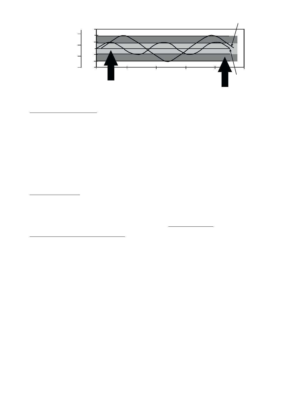
27
Low Cooler Suction Temperature — To avoid freezing the
cooler, the control will compare the circuit Cooler Suction tem-
perature (T5/T6) with a predetermined freeze point. If the cool-
er fluid selected is Water, the freeze point is 34 F (1.1 C). If the
cooler fluid selected is Brine, the freeze point is 8° F (4.4 ° C)
below the cooling set point (or lower of two cooling set points
in dual set point configurations). If the cooler suction tempera-
ture is 24° to 29° F (13.3° to 16.1° C) below the cooler leaving
water temperature and is also 2° F (1.1° C) less than the freeze
point for 5 minutes, Mode 7 (Circuit A) or Mode 8 (Circuit B)
is initiated and no additional capacity increase is allowed. The
circuit will be allowed to run in this condition. If the cooler suc-
tion temperature is more than 30° F (16.7° C) below the cooler
leaving water temperature and is also 2° F (1.1° C) below the
freeze point for 10 minutes, the circuit will be stopped without
going through pumpdown.
Cooler Freeze Protection — The control will try to prevent
shutting the chiller down on a Cooler Freeze Protection alarm
by removing stages of capacity. The control uses the same
freeze point logic as described in the Low Cooler Suction Tem-
perature section above. If the cooler leaving fluid temperature
is less than the freeze point plus 2.0° F (1.1° C), the control will
immediately remove one stage of capacity. This can be repeat-
ed once every 30 seconds.
MOP (Maximum Operating Pressure) Override — The con-
trol monitors saturated condensing and suction temperature for
each circuit. Based on a maximum operating set point (saturat-
ed suction temperature), the control may lower the EXV posi-
tion when system pressures approach the set parameters.
Head Pressure Control
COMFORTLINK™ UNITS (With EXV) — The Main Base
Board (MBB) controls the condenser fans to maintain the low-
est condensing temperature possible, and thus the highest unit
efficiency. The fans are controlled by the saturated condensing
temperature set from the factory. The fans can also be con-
trolled by a combination of the saturated condensing tempera-
ture, EXV position and compressor superheat. Fan control is a
configurable decision and is determined by the Head Pressure
Control Method (HPCM) setting in the Configuration Mode
under the OPT1 sub-mode. For EXV control (HPCM = 1),
when the position of the EXV is fully open, T3 and T4 are less
than 78 F (25.6 C), and superheat is greater than 40 F (22.2 C),
fan stages will be removed. When the valve is less than 40%
open, or T3 and T4 are greater than 113 F (45 C), fan stages
will be added. At each change of the fan stage, the system will
wait one minute to allow the head pressure to stabilize unless
either T3 or T4 is greater than 125 F (51.6 C), in which case all
MBB-controlled fans will start immediately. This method
allows the unit to run at very low condensing temperatures at
part load.
During the first 10 minutes after circuit start-up, MBB-
controlled fans are not turned on until T3 and T4 are greater
than the head pressure set point plus 10 F (5.6 C). If T3 and T4
are greater than 95 F (35 C) just prior to circuit start-up, all
MBB-controlled fan stages are turned on to prevent excessive
discharge pressure during pull-down. Fan sequences are shown
in Fig. 17.
UNITS WITH TXV — The logic to cycle MBB-controlled
fans is based on saturated condensing temperature only, as
sensed by thermistors T3 and T4 (see Fig. 8 and 10). When
either T3 or T4 exceeds the head pressure set point, the MBB
will turn on an additional stage of fans. For the first 10 minutes
of each circuit operation, the head pressure set point is raised
by 10° F (5.6° C). It will turn off a fan stage when T3 and T4
are both below the head pressure set point by 35° F (19.4° C).
At each change of a fan stage the control will wait for one
minute for head pressure to stabilize unless T3 and T4 is great-
er than 125 F (51.6 C), in which case all MBB-controlled fans
start immediately. If T3 and T4 are greater than 95 F (35.0 C)
just prior to circuit start-up, all MBB-controlled fan stages are
turned on to prevent excessive discharge pressure during pull-
down. Fan sequences are shown in Fig. 18.
Motormaster® Option — For low-ambient operation, the lead
fan(s) in each circuit can be equipped with the Motormaster III
head pressure controller option or accessory. Wind baffles and
brackets must be field-fabricated for all units using accessory
Motormaster III controls to ensure proper cooling cycle opera-
tion at low-ambient temperatures. The fans controlled are those
that are energized with the lead compressor in each circuit. All
sizes use one controller per circuit. Refer to Fig. 18 for con-
denser fan staging information.
Pumpout
EXV UNITS — When the lead compressor in each circuit is
started or stopped, that circuit goes through a pumpout cycle to
purge the cooler and refrigerant suction lines of refrigerant. If a
circuit is starting within 15 minutes of the last shutdown, the
pumpout cycle will be skipped.
The pumpout cycle starts immediately upon starting the
lead compressor and keeps the EXV at minimum position for
10 seconds. The EXV is then opened an additional percentage
and compressor superheat control begins. At this point, the
EXV opens gradually to provide a controlled start-up to pre-
vent liquid flood-back to the compressor.
At shutdown, the pumpout cycle continuously closes the
EXV until all lag compressors are off and the EXV is at 0%.
The lead compressor continues to run for an additional 10 sec-
onds and is then shut off.
TXV UNITS — Pumpout is based on timed pumpout. On a
command for start-up, the lead compressor starts. After 15 sec-
onds, the liquid line solenoid opens. At shutdown, the liquid
line solenoid closes when the lead compressor has stopped.
47
46
45
44
43
42
41
0 200 400 600 800 1000
TIME (SECONDS)
2 STARTS
3 STARTS
DEADBAND EXAMPLE
LWT (F)
MODIFIED
DEADBAND
STANDARD
DEADBAND
8
7
6
5
LWT (C)
Fig. 17 — Deadband Multiplier
LEGEND
LWT — Leaving Water Temperature
28
*Control box.
†Fan numbers 11 and 12 do not apply to 30GTN,R and 30GUN,R 130-170 and associated modular units (see Table 1).
Fig. 18 — Condenser Fan Sequence
FAN ARRANGEMENT FAN
NO. FAN RELAY NORMAL CONTROL
30GTN,R040-050
30GUN,R040-050 1—Compressor No. A1
2—Compressor No. B1
3 1 First Stage of Condenser Fans
4 2 Second Stage of Condenser Fans
30GTN,R060-090, 230B, 245B
30GUN,R060-090, 230B, 245B 1—Compressor No. A1
2—Compressor No. B1
3, 4 1 First Stage of Condenser Fans
5, 6 2 Second Stage of Condenser Fans
30GTN,R100,110, 255B-315B
30GUN,R100,110, 255B-315B 1—Compressor No. A1
2—Compressor No. B1
3, 4 1 First Stage of Condenser Fans
5, 6, 7, 8 2 Second Stage of Condenser Fans
30GTN,R130 (60 Hz),
30GUN,R130 (60 Hz)
POWER
5, 7 —Compressor No. A1
6, 8 —Compressor No. B1
1, 2 1 First Stage of Condenser Fans
3, 4, 9, 10 2 Second Stage of Condenser Fans
30GTN,R130 (50 Hz), 150-210,
230A-315A, 330A/B-420A/B†
30GUN,R130 (50 Hz), 150-210,
230A-315A, 330A/B-420A/B†
POWER
5, 7 —Compressor No. A1
6, 8 —Compressor No. B1
1, 11 1 First Stage of Condenser Fans, Circuit A
3, 9 2 Second Stage of Condenser Fans, Circuit A
2, 12 3 First Stage of Condenser Fans, Circuit B
4, 10 4 Second Stage of Condenser Fans, Circuit B
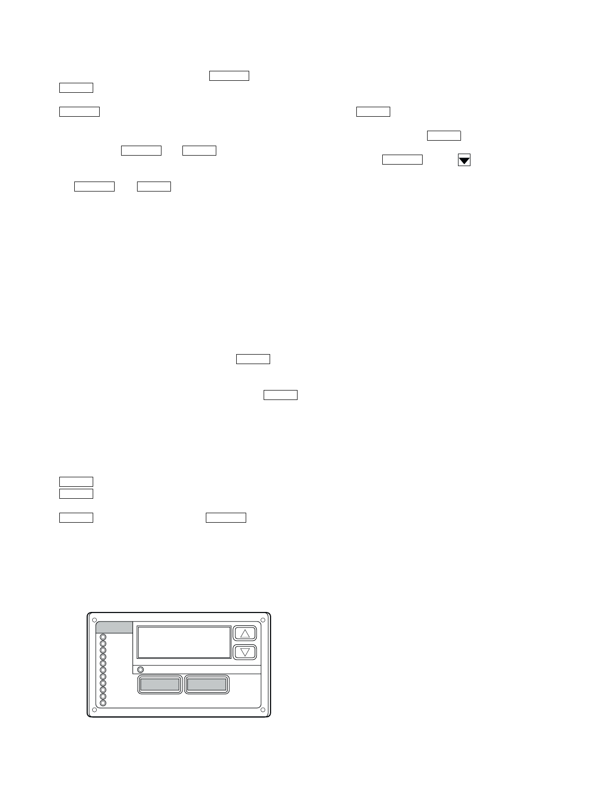
29
Marquee Display Usage (See Fig. 19 and
Tables 7-25) — The Marquee display module provides the
user interface to the ComfortLink™ control system. The dis-
play has up and down arrow keys, an key, and an
key. These keys are used to navigate through the dif-
ferent levels of the display structure. See Table 7. Press the
key until the display is blank to move through the
top 11 mode levels indicated by LEDs on the left side of the
display.
Pressing the and keys simultaneously
will scroll a clear language text description across the display
indicating the full meaning of each display acronym. Pressing
the and keys when the display is blank
(Mode LED level) will return the Marquee display to its default
menu of rotating display items. In addition, the password will
be disabled requiring that it be entered again before changes
can be made to password protected items.
Clear language descriptions in English, Spanish, French, or
Portuguese can be displayed when properly configuring the
LANG variable in the Configuration mode, under DISP sub-
mode. See Table 16.
NOTE: When the LANG variable is changed to 1, 2, or 3, all
appropriate display expansions will immediately change to the
new language. No power-off or control reset is required when
reconfiguring languages.
When a specific item is located, the display will flash show-
ing the operator, the item, followed by the item value and then
followed by the item units (if any). Press the key to
stop the display at the item value. Items in the Configuration
and Service Test modes are password protected. The display
will flash PASS and WORD when required. Use the
and arrow keys to enter the 4 digits of the password. The de-
fault password is 1111. The password can only be changed
through CCN devices such as ComfortWORKS® and Service
Tool.
Changing item values or testing outputs is accomplished in
the same manner. Locate and display the desired item. Press
to stop the display at the item value. Press the
key again so that the item value flashes. Use the ar-
row keys to change the value or state of an item and press the
key to accept it. Press the key and the
item, value, or units display will resume. Repeat the process as
required for other items.
See Tables 7-25 for further details.
Service Test (See Table 9) — Both main power and
control circuit power must be on.
The Service Test function should be used to verify proper
operation of compressors, unloaders, hot gas bypass (if in-
stalled), cooler pump and remote alarm relays, EXVs and con-
denser fans. To use the Service Test mode, the Enable/Off/
Remote Contact switch must be in the OFF position. Use the
display keys and Table 9 to enter the mode and display TEST.
Press twice so that OFF flashes. Enter the password if
required. Use either arrow key to change the TEST value to the
On position and press . Switch the Enable/Off/Re-
mote Contact switch to the Enable position (Version 2.3 and
later). Press and the button to enter the OUTS
or COMP sub-mode.
Test the condenser fan, cooler pump, and alarm relays by
changing the item values from OFF to ON. These discrete out-
puts are turned off if there is no keypad activity for 10 minutes.
Use arrow keys to select desired percentage when testing ex-
pansion valves. When testing compressors, the lead compres-
sor must be started first. All compressor outputs can be turned
on, but the control will limit the rate by staging one compressor
per minute. Compressor unloaders and hot gas bypass relays/
solenoids (if installed) can be tested with compressors on or
off. The relays under the COMP sub-mode will stay on for
10 minutes if there is no keypad activity. Compressors will stay
on until they are turned off by the operator. The Service Test
mode will remain enabled for as long as there is one or more
compressors running. All safeties are monitored during this test
and will turn a compressor, circuit or the machine off if re-
quired. Any other mode or sub-mode can be accessed, viewed,
or changed during the TEST mode. The MODE item (Run Sta-
tus mode under sub-mode VIEW) will display “0” as long as
the Service mode is enabled. The TEST sub-mode value must
be changed back to OFF before the chiller can be switched to
Enable or Remote contact for normal operation.
Configuring and Operating Dual Chiller Con-
trol (See Table 18) — The dual chiller routine is avail-
able for the control of two units supplying chilled fluid on a
common loop. This control is designed for a parallel fluid flow
arrangement only. One chiller must be configured as the master
chiller, the other as the slave chiller. An additional leaving fluid
temperature thermistor (Dual Chiller LWT) must be installed
as shown in Fig. 20 and connected to the master chiller. See
Field Wiring section for Dual Chiller LWT sensor wiring.
To configure the two chillers for operation, follow the ex-
ample shown in Table 18. The master chiller will be configured
with a slave chiller at address 6. Also in this example, the mas-
ter chiller will be configured to use Lead/Lag Balance to even
out the chiller runtimes weekly. The Lag Start Delay feature
will be set to 10 minutes. The master and slave chillers cannot
have the same CCN address (CCNA, Configuration mode un-
der OPT2). Both chillers must have the control method variable
(CTRL, Configuration mode under OPT2) set to ‘3.’ In addi-
tion, the chillers must both be connected together on the same
CCN bus. Connections can be made to the CCN screw termi-
nals on TB3 in both chillers. The master chiller will determine
which chiller will be Lead and which will be Lag. The master
chiller controls the slave chiller by forcing the slave chiller’s
CCN START/STOP variable (CHIL_S_S), control point
(CTPT) and demand limit (DEM_LIM).
The master chiller is now configured for dual chiller opera-
tion. To configure the slave chiller, only the LLEN and MSSL
variables need to be set. Enable the Lead/Lag chiller enable
variable (LLEN) as shown Table 18. Similarly, set the Master/
Slave Select variable (MSSL) to SLVE. The variables LLBL,
LLBD, an LLDY are not used by the slave chiller.
Refer to Field Wiring section on page 67 for wiring
information.
ESCAPE
ENTER
ESCAPE
ESCAPE ENTER
ESCAPE ENTER
ENTER
ENTER
ENTER
ENTER
ENTER ESCAPE
ENTER
ENTER
ESCAPE
Run Status
Service Test
Temperature
Pressures
Setpoints
Inputs
Outputs
Configuration
Time Clock
Operating Modes
Alarms
Alarm Status
ENTER
MODE
ESCAPE
Fig. 19 — Scrolling Marquee Display
30
Table 7 — Marquee Display Menu Structure
LEGEND
Ckt — Circuit
RUN
STATUS
SERVICE
TEST TEMPERATURES PRESSURES SET
POINTS INPUTS OUTPUTS CONFIGURATION TIME
CLOCK
OPERATING
MODES ALARMS
Auto
Display
(VIEW)
Manual
Mode
On/Off
(TEST)
Unit
Temperatures
(UNIT)
Ckt A
Pressures
(PRC.A)
Cooling
(COOL)
Unit
Discrete
(GEN.I)
Unit
Discrete
(GEN.O)
Display
(DISP)
Unit Time
(TIME)
Modes
(MODE)
Current
(CRNT)
Machine
Hours/Starts
(RUN)
Ckt A/B
Outputs
(OUTS)
Ckt A
Temperatures
(CIR.A)
Ckt B
Pressures
(PRC.B)
Heating
(HEAT)
Ckt A/B
(CRCT)
Ckt A
(CIR.A)
Machine
(UNIT)
Unit Date
(DATE)
Reset
Alarms
(RCRN)
Compressor
Run Hours
(HOUR)
Compressor
Tests
(COMP)
Ckt B
Temperatures
(CIR.B)
Head
Pressure
(HEAD)
Unit
Analog
(4-20)
Ckt B
(CIR.B)
Options 1
(OPT1)
Schedule
(SCHD)
Alarm
History
(HIST)
Compressor
Starts
(STRT)
Options 2
(OPT2)
Reset
History
(RHIS)
Software
Version
(VERS)
Temperature
Reset
(RSET)
Set Point
Select
(SLCT)
MASTER
CHILLER
SLAVE
CHILLER
LEAVING
FLUID
INSTALL DUAL CHILLER
LEAVING FLUID
THERMISTOR (T9) HERE
RETURN
FLUID
THERMISTOR
WIRING*
*Depending on piping sizes, use either:
— HH79NZ014 sensor and 10HB50106801 well (3-in. sensor/well)
— HH79NZ029 sensor and 10HB50106802 well (4-in. sensor/well)
Fig. 20 — Dual Chiller Thermistor Location
31
Table 8 — Run Status Mode and Sub-Mode Directory
SUB-MODE KEYPAD
ENTRY ITEM RANGE ITEM EXPANSION COMMENT
VIEW EWT 0 - 100 F
(–18 - 38 C) ENTERING FLUID TEMP
LWT 0 - 100 F
(–18 - 38 C) LEAVING FLUID TEMP
SETP 0 - 100 F
(–18 - 38 C) ACTIVE SETPOINT
CTPT 0 - 100 F
(–18 - 38 C) CONTROL POINT
STAT 0 - 7 CONTROL MODE 0 = Service Test
1 = Off Local
2 = Off CCN
3 = Off Time Clock
4 = Off Emergency
5 = On Local
6 = On CCN
7 = On Time Clock
OCC NO-YES OCCUPIED
MODE NO-YES OVERRIDE MODE IN EFFECT
CAP 0 - 100% PERCENT TOTAL CAPACITY
STGE 0 - 30 REQUESTED STAGE
ALRM 0 - 25 CURRENT ALARMS & ALERTS
TIME 00.00 - 23.59 TIME OF DAY
MNTH 1 - 12 MONTH OF YEAR 1 = Jan., 2 = Feb
DATE 1 - 31 DAY OF MONTH
YEAR 0 - 9999 YEAR OF CENTURY
RUN HRS.U 0 - 999999 MACHINE OPERATING HOURS
STR.U 0 - 999999 MACHINE STARTS
HOUR HRS.A 0 - 999999 CIRCUIT A RUN HOURS
HRS.B 0 - 999999 CIRCUIT B RUN HOURS
HR.A1 0 - 999999 COMPRESSOR A1 RUN HOURS
HR.A2 0 - 999999 COMPRESSOR A2 RUN HOURS
HR.A3 0 - 999999 COMPRESSOR A3 RUN HOURS
HR.A4 0 - 999999 COMPRESSOR A4 RUN HOURS
HR.B1 0 - 999999 COMPRESSOR B1 RUN HOURS
HR.B2 0 - 999999 COMPRESSOR B2 RUN HOURS
HR.B3 0 - 999999 COMPRESSOR B3 RUN HOURS
HR.B4 0 - 999999 COMPRESSOR B4 RUN HOURS
STRT ST.A1 0 - 999999 COMPRESSOR A1 STARTS
ST.A2 0 - 999999 COMPRESSOR A2 STARTS
ST.A3 0 - 999999 COMPRESSOR A3 STARTS
ST.A4 0 - 999999 COMPRESSOR A4 STARTS
ST.B1 0 - 999999 COMPRESSOR B1 STARTS
ST.B2 0 - 999999 COMPRESSOR B2 STARTS
ST.B3 0 - 999999 COMPRESSOR B3 STARTS
ST.B4 0 - 999999 COMPRESSOR B4 STARTS
VERS MBB CESR-131170-XX-XX
EXV CESR-131172-XX-XX
CXB CESR-131173-XX-XX
EMM CESR-131174-XX-XX
MARQ CESR-131171-XX-XX
NAV CESR-131227-XX-XX
ENTER
ENTER
ENTER
ENTER
ENTER

32
Table 9 — Service Test Mode and Sub-Mode Directory
LEGEND
EXV — Electronic Expansion Valve
SUB-MODE KEYPAD
ENTRY ITEM RANGE ITEM EXPANSION COMMENT
TEST TEST OFF-ON SERVICE TEST MODE Use to Enable/Disable Manual Mode
OUTS LLS.A OPEN-CLSE LIQ. LINE SOLENOID VALVE TXV units only
EXV.A 0 - 100% EXV % OPEN
LLS.B OPEN-CLSE LIQ. LINE SOLENOID VALVE TXV units only
EXV.B 0 - 100% EXV % OPEN
FAN1 OFF-ON FAN 1 RELAY Fan 3: (040-050)
Fans 3, 4: (060-110, 230B-315B)
Fans 1, 2: (130 [60 Hz])
Fans 1: (130 [50 Hz], 150, 170,
230A-270A, 330A/B, 360B [50 Hz])
Fans 1, 11: (190-210, 290A, 315A,
360A, 360B [60 Hz], 390A/B-420A/B)
FAN2 OFF-ON FAN 2 RELAY Fan 4: (040-050)
Fans 5, 6: (060-090, 230B-245B)
Fans 5, 6, 7, 8: (100, 110, 255B-315B)
Fans 3, 4, 9, 10: (130 [60 Hz])
Fan 2: (130 [50 Hz], 150, 170,
230A-270A, 330A/B, 360B [50 Hz])
Fans 2, 12: (190-210, 290A, 315A,
360A, 360B [60 Hz], 390A/B-420A/B)
FAN3 OFF-ON FAN 3 RELAY Fans 3, 9: (130 [50 Hz], 150-210,
230A-315A, 330A/B-420A/B)
FAN4 OFF-ON FAN 4 RELAY Fans 4, 10: (130 [50 Hz], 150-210,
230A-315A, 330A/B-420A/B)
CLR.P OFF-ON COOLER PUMP RELAY
CND.P OFF-ON CONDENSER PUMP RELAY
RMT.A OFF-ON REMOTE ALARM RELAY
COMP CC.A1 OFF-ON COMPRESSOR A1 RELAY
CC.A2 OFF-ON COMPRESSOR A2 RELAY
CC.A3 OFF-ON COMPRESSOR A3 RELAY
CC.A4 OFF-ON COMPRESSOR A4 RELAY
UL.A1 OFF-ON UNLOADER A1 RELAY
UL.A2 OFF-ON UNLOADER A2 RELAY
HGBP OFF-ON HOT GAS BYPASS RELAY
CC.B1 OFF-ON COMPRESSOR B1 RELAY
CC.B2 OFF-ON COMPRESSOR B2 RELAY
CC.B3 OFF-ON COMPRESSOR B3 RELAY
CC.B4 OFF-ON COMPRESSOR B4 RELAY
UL.B1 OFF-ON UNLOADER B1 RELAY
UL.B2 OFF-ON UNLOADER B2 RELAY
ENTER
ENTER
ENTER
33
Table 10 — Temperature Mode and Sub-Mode Directory
Table 11 — Pressure Mode and Sub-Mode Directory
Table 12 — Set Point Mode and Sub-Mode Directory
SUB-MODE KEYPAD
ENTRY ITEM RANGE ITEM EXPANSION COMMENT
UNIT CEWT –40 - 245 F
(–40 - 118 C) COOLER ENTERING FLUID
CLWT –40 - 245 F
(–40 - 118 C) COOLER LEAVING FLUID
OAT –40 - 245 F
(–40 - 118 C) OUTSIDE AIR TEMPERATURE
SPT –40 - 245 F
(–40 - 118 C) SPACE TEMPERATURE
CNDE –40 - 245 F
(–40 - 118 C)
CONDENSER ENTERING FLUID
CNDL –40 - 245 F
(–40 - 118 C)
CONDENSER LEAVING FLUID
DLWT –40 - 245 F
(–40 - 118 C)
LEAD/LAG LEAVING FLUID
CIR.A SCT.A –40 - 245 F
(–40 - 118 C) SATURATED CONDENSING TMP
SST.A –40 - 245 F
(–40 - 118 C) SATURATED SUCTION TEMP
SGT.A –40 - 245 F
(–40 - 118 C) COMPRESSOR SUCTION GAS TEMP
SUP.A –40 - 245 ∆ F
(–40 - 118 ∆ C) SUCTION SUPERHEAT TEMP
CIR.B SCT.B –40 - 245 F
(–40 - 118 C) SATURATED CONDENSING TMP
SST.B –40 - 245 F
(–40 - 118 C) SATURATED SUCTION TEMP
SGT.B –40 - 245 F
(–40 - 118 C) COMPRESSOR SUCTION GAS TEMP
SUP.B –40 - 245 ∆ F
(–40 - 118 ∆ C) SUCTION SUPERHEAT TEMP
SUB-MODE KEYPAD ENTRY ITEM RANGE ITEM EXPANSION COMMENT
PRC.A DP.A 0-900
Psig DISCHARGE PRESSURE Pressure is converted from SCT.A.
SP.A 0-900
Psig SUCTION PRESSURE Pressure is converted from SST.A.
PRC.B DP.B 0-900
Psig DISCHARGE PRESSURE Pressure is converted from SCT.B.
SP.B 0-900
Psig SUCTION PRESSURE Pressure is converted from SST.B.
SUB-MODE KEYPAD
ENTRY ITEM RANGE ITEM EXPANSION COMMENT
COOL CSP.1 –20 - 70 F
(–29 - 21 C) COOLING SETPOINT 1 Default 44 F
CSP.2 –20 - 70 F
(–29 - 21 C) COOLING SETPOINT 2 Default 44 F
CSP.3 –20 - 32 F
(–29 - 0° C) ICE SETPOINT Default 32 F
HEAT HSP.1 80 - 140 F
(27 - 60 C) HEATING SETPOINT 1 Not Supported
HSP.2 80 - 140 F
(27 - 60 C) HEATING SETPOINT 2 Not Supported
HEAD HD.P.A 80 - 140 F
(27 - 60 C) HEAD PRESSURE SETPOINT A Default 113 F
HD.P.B 80 - 140 F
(27 - 60 C) HEAD PRESSURE SETPOINT B Default 113 F
ENTER
ENTER
ENTER
ENTER
ENTER
ENTER
ENTER
34
Table 13 — Reading and Changing Chilled Fluid Set Point
Table 14 — Inputs Mode and Sub-Mode Directory
SUB-MODE KEYPAD ENTRY ITEM DISPLAY RANGE ITEM EXPANSION COMMENT
COOL
CSP.1 44.0 °F–20-70 F COOLING SETPOINT 1
Default: 44 F
38-70 F Flud = 1
14-70 F Flud = 2
–20-70 F Flud = 3
44.0 °F–20-70 F Scrolling stops
44.0 °F–20-70 F Value flashes
–20-70 F Select 46.0
46.0 °F–20-70 F Change accepted
CSP.1 46.0 °F–20-70 F COOLING SETPOINT 1 Item/Value/Units scrolls again
SUB-MODE KEYPAD
ENTRY ITEM RANGE ITEM EXPANSION COMMENT
GEN.I STST STRT-STOP START/STOP SWITCH Enable/Off/Remote
Contact Switch Input
FLOW OFF-ON COOLER FLOW SWITCH
CND.F OFF-ON CONDENSER FLOW SWITCH
DLS1 OFF-ON DEMAND LIMIT SWITCH 1
DLS2 OFF-ON DEMAND LIMIT SWITCH 2
ICED OFF-ON ICE DONE
DUAL OFF-ON DUAL SETPOINT SWITCH
CRCT FKA1 OFF-ON COMPRESSOR A1 FEEDBACK
FKA2 OFF-ON COMPRESSOR A2 FEEDBACK
FKA3 OFF-ON COMPRESSOR A3 FEEDBACK
FKA4 OFF-ON COMPRESSOR A4 FEEDBACK
OIL.A OPEN-CLSE OIL PRESSURE SWITCH A
LPS.A OPEN-CLSE LOW PRESSURE SWITCH Not applicable (040-420)
FKB1 OFF-ON COMPRESSOR B1 FEEDBACK
FKB2 OFF-ON COMPRESSOR B2 FEEDBACK
FKB3 OFF-ON COMPRESSOR B3 FEEDBACK
FKB4 OFF-ON COMPRESSOR B4 FEEDBACK
OIL.B OPEN-CLSE OIL PRESSURE SWITCH B
LPS.B OPEN-CLSE LOW PRESSURE SWITCH Not applicable (040-420)
4-20 DMND 0 - 24 mA 4-20 mA DEMAND SIGNAL
RSET 0 - 24 mA 4-20 mA RESET SIGNAL
CSP 0 - 24 mA 4-20 mA COOLING SETPOINT
HSP 0 - 24 mA 4-20 mA HEATING SETPOINT
ENTER
ENTER
ENTER
ENTER
ENTER
ENTER
ENTER
ENTER
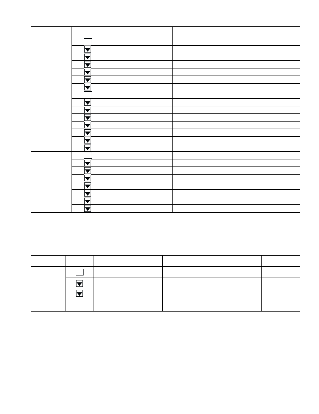
35
Table 15 — Outputs Mode and Sub-Mode Directory
LEGEND
Table 16 — Configuration Mode and Sub-Mode Directory
LEGEND
SUB-MODE KEYPAD
ENTRY ITEM RANGE ITEM EXPANSION COMMENT
GEN.O FAN1 OFF-ON FAN 1 RELAY
FAN2 OFF-ON FAN 2 RELAY
FAN3 OFF-ON FAN 3 RELAY
FAN4 OFF-ON FAN 4 RELAY
C.PMP OFF-ON COOLER PUMP RELAY
H.GAS OFF-ON HOT GAS BYPASS RELAY
CNDP OFF-ON CONDENSER PUMP RELAY
CIR.A CC.A1 OFF-ON COMPRESSOR A1 RELAY
CC.A2 OFF-ON COMPRESSOR A2 RELAY
CC.A3 OFF-ON COMPRESSOR A3 RELAY
CC.A4 OFF-ON COMPRESSOR A4 RELAY
ULA1 OFF-ON UNLOADER A1 RELAY
ULA2 OFF-ON UNLOADER A2 RELAY TXV units only
LLS.A OPEN-CLSE LIQUID LINE SOLENOID VLV EXV units only
EXV.A 0 - 100% EXV % OPEN
CIR.B CC.B1 OFF-ON COMPRESSOR B1 RELAY
CC.B2 OFF-ON COMPRESSOR B2 RELAY
CC.B3 OFF-ON COMPRESSOR B3 RELAY
CC.B4 OFF-ON COMPRESSOR B4 RELAY
ULB1 OFF-ON UNLOADER B1 RELAY
ULB2 OFF-ON UNLOADER B2 RELAY
LLS.B OPEN-CLSE LIQUID LINE SOLENOID VLV TXV units only
EXV.B 0 - 100% EXV % OPEN EXV units only
EXV —Electronic Expansion Valve
TXV —Thermostatic Expansion Valve
ENTER
ENTER
ENTER
SUB-MODE KEYPAD
ENTRY ITEM MARQUEE
DISPLAY RANGE
NAVIGATOR
DISPLAY RANGE ITEM EXPANSION COMMENT
DISP TEST OFF-ON OFF-ON TEST DISPLAY
LEDS
METR OFF-ON OFF-ON METRIC DISPLAY Off = English
On = Metric
LANG 0 - 3 ENGLISH
ESPANOL
FRANCAIS
PORTUGUES
LANGUAGE
SELECTION
Default: 0
0 = English
1 = Espanol
2 = Francais
3 = Portugues
CCN —Carrier Comfort Network
EMM —Energy Management Module
EXV —Electronic Expansion Valve
LCW —Leaving Chilled Water
ENTER
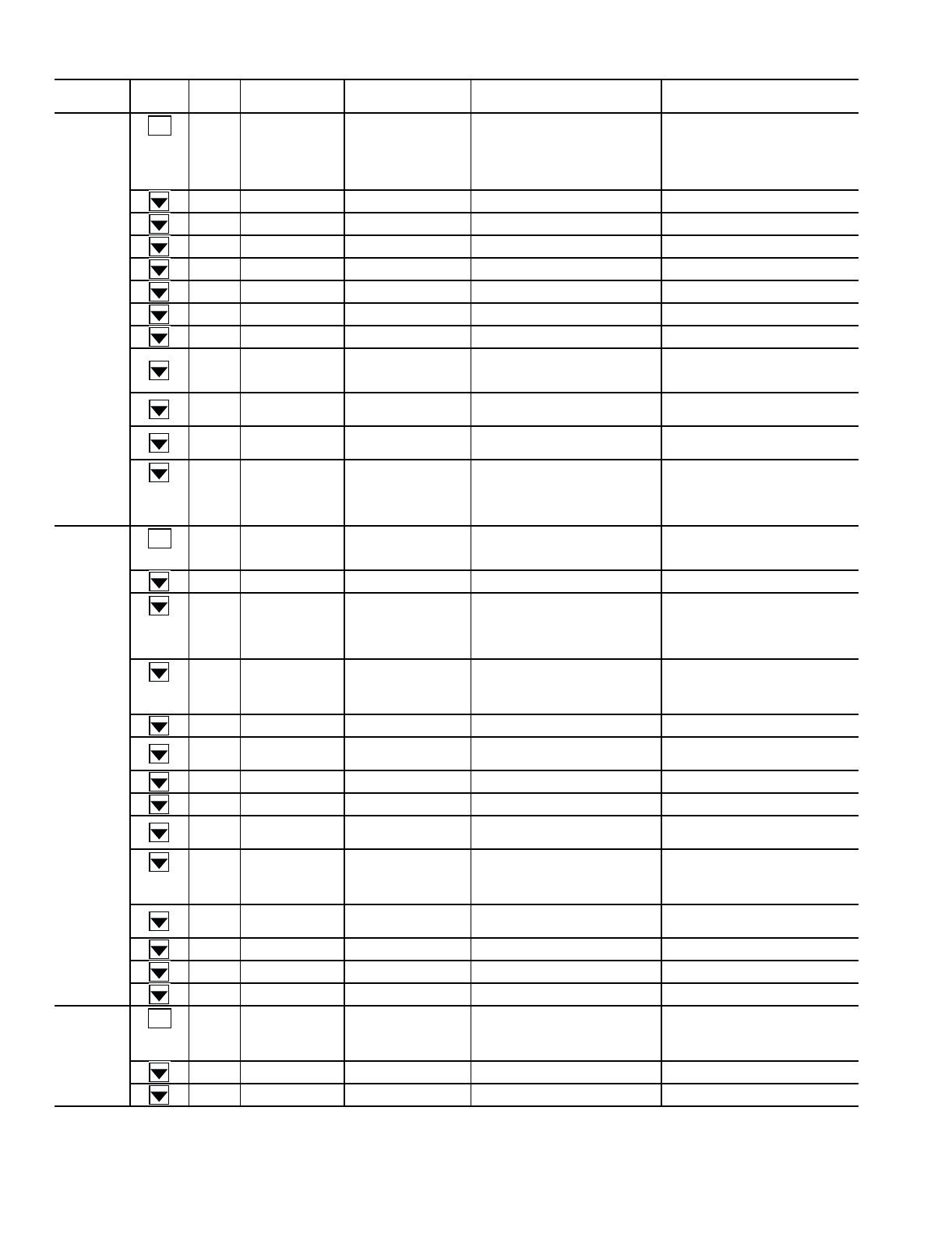
36
Table 16 — Configuration Mode and Sub-Mode Directory (cont)
LEGEND
SUB-MODE KEYPAD
ENTRY ITEM MARQUEE
DISPLAY RANGE
NAVIGATOR
DISPLAY RANGE ITEM EXPANSION COMMENT
UNIT TYPE 1 - 5 AIR COOLED
WATER COOLED
SPLIT
HEAT MACHINE
HEAT RECLAIM
UNIT TYPE Default: 1
1 = Air Cooled
2 = Water Cooled
3 = Split System
4 = Heat Machine
5 = Heat Reclaim
TONS 15 - 300 15 - 300 UNIT SIZE
CAP.A 0 - 100% 0 - 100% CIRCUIT A % CAPACITY
CMP.A 1 - 4 1 - 4 NUMBER CIRC A COMPRESSOR
CYL.A 4, 6 4, 6 COMPRESSOR A1 CYLINDERS
CMP.B 1 - 4 1 - 4 NUMBER CIRC B COMPRESSOR
CYL.B 4, 6 4, 6 COMPRESSOR B1 CYLINDERS
EXV NO-YES NO-YES EXV MODULE INSTALLED
SH.SP 10 - 40 ∆ F
(6 - 22 ∆ C)
10 - 40 ∆ F
(6 - 22 ∆ C) EXV SUPERHEAT SETPOINT
Default
29 = 30GTN,R
23 = 30GUN,R
SH.OF –20 - 20 ∆ F
(–11 - 11 ∆ C)
–20 - 20 ∆ F
(–11 - 11 ∆ C) EXV SUPERHEAT OFFSET Default: 0
REFG 1, 2 1, 2 REFRIGERANT 1 = R-22 (30GTN,R)
2 = R-134a (30GUN,R)
FAN.S 1 - 4 2 STAGE IND
3 STAGE IND
2 STAGE COM
3 STAGE COM
FAN STAGING SELECT 1 = 2 Stage Independent
2 = 3 Stage Independent
3 = 2 Stage Common
4 = 3 Stage Common (Not supported
for air cooled)
OPT1 FLUD 1 - 3 1 - 3 COOLER FLUID 1 = Water
2 = Med. Brine
3 = Low Brine
HGB.S NO-YES NO-YES HOT GAS BYPASS SELECT
HPCM 1 - 4 EXV CONTROL
SETPOINT CONTROL
SET A EXV B
EXV A SET B
HEAD PRESS. CONT. METHOD Default:2
1 = EXV Control
2 = Set Point Control
3 = Set Point Circuit A, EXV Circuit B
4 = Set Point Circuit B, EXV Circuit A
HPCT 0 - 2 NO CONTROL
AIR COOLED
WATER COOLED
HEAD PRESS. CONTROL TYPE Default: 1
0 = No Control
1 = Air Cooled
2 = Water Cooled
MMR.S NO-YES NO-YES MOTORMASTER SELECT
PRTS NO-YES NO-YES PRESSURE
TRANSDUCERS
Default: NO
Not Supported
PMP.I OFF-ON OFF-ON COOLER PUMP INTERLOCK Default: ON
CPC OFF-ON OFF-ON COOLER PUMP CONTROL Default: OFF
CNP.I OFF-ON OFF-ON CONDENSER PUMP INTERLOCK Default: OFF
Not Applicable
CNPC 0 - 2 NO CONTROL
ON WITH MODE
ON WITH COMP
CONDENSER PUMP CONTROL Default: 0
0 = Not Controlled
1 = On with Occupied Mode
2 = On with Compressors
CWT.S NO-YES NO-YES CONDENSER FLUID SENSORS Default: NO
Not Applicable
CA.UN 0 - 2 0 - 2 NO. CIRCUIT A UNLOADERS
CB.UN 0 - 2 0 - 2 NO. CIRCUIT B UNLOADERS
EMM NO-YES NO-YES EMM MODULE INSTALLED
OPT2 CTRL 0 - 3 SWITCH
7 DAY OCC
OCCUPANCY
CCN
CONTROL METHOD 0 = Switch
1 = 7-Day Schedule
2 = Occupancy Schedule
3 = CCN
CCNA 1 - 239 1 - 239 CCN ADDRESS Default: 1
CCNB 0 - 239 0 - 239 CCN BUS NUMBER Default: 0
CCN —Carrier Comfort Network
EMM —Energy Management Module
EXV —Electronic Expansion Valve
LCW —Leaving Chilled Water
ENTER
ENTER
ENTER
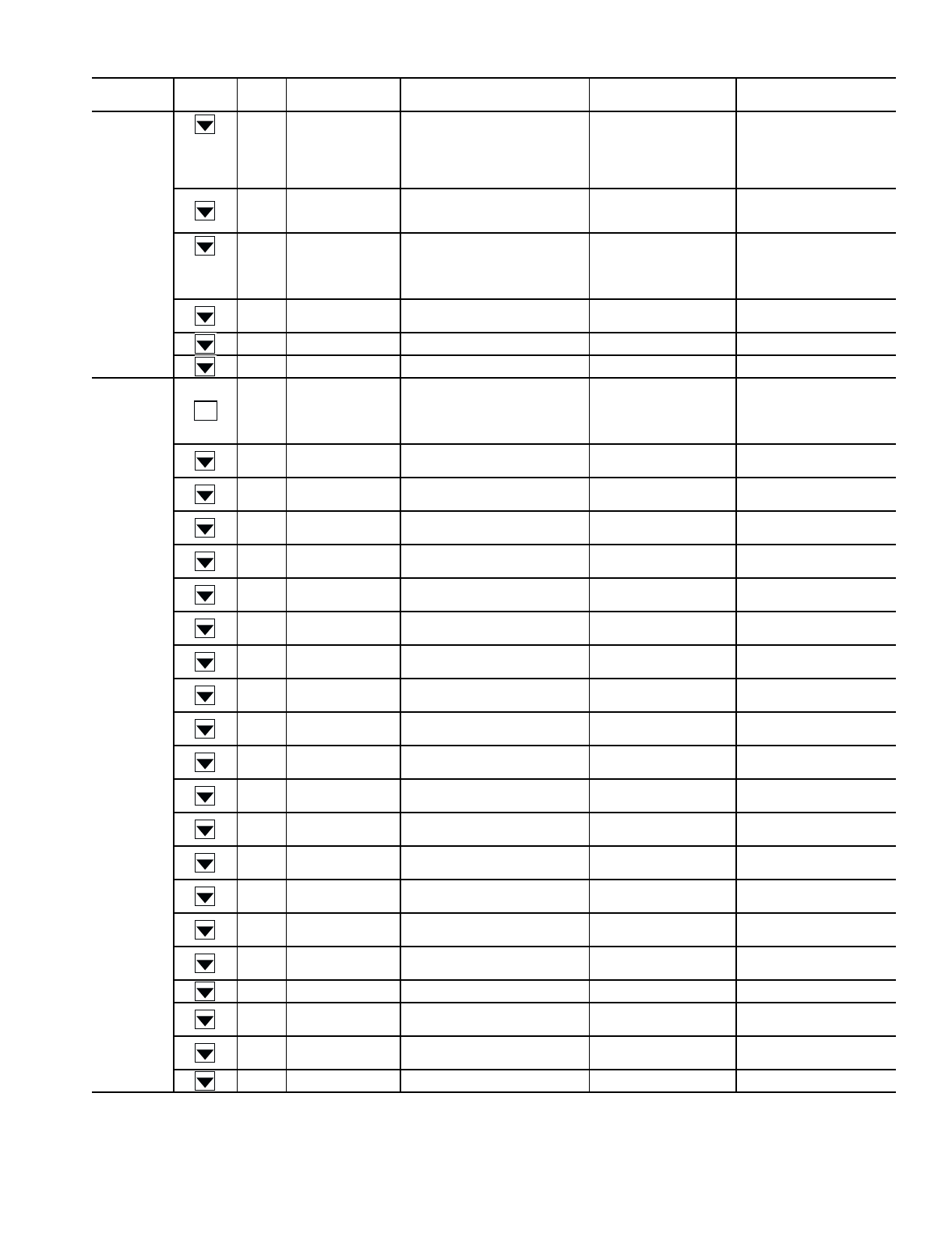
37
Table 16 — Configuration Mode and Sub-Mode Directory (cont)
SUB-MODE KEYPAD
ENTRY ITEM MARQUEE
DISPLAY RANGE
NAVIGATOR
DISPLAY RANGE ITEM EXPANSION COMMENT
OPT2
(cont)
BAUD 1 - 5 2400
4800
9600
19,200
38,400
CCN BAUD RATE Default: 3
1 = 2400
2 = 4800
3 = 9600
4 = 19,200
5 = 38,400
LOAD 1 - 2 EQUAL
STAGED
LOADING SEQUENCE
SELECT
Default: 1
1 = Equal
2 = Staged
LLCS 1 - 3 AUTOMATIC
CIR A LEADS
CIR B LEADS
LEAD/LAG CIRCUIT
SELECT
Default: 1 (Size 080-420);
2 (Size 040-070)
1 = Automatic
2 = Circuit A Leads
3 = Circuit B Leads
LCWT 2 - 60 ∆ F
(–16 - 16 ∆ C)
2 - 60 ∆ F
(–16 - 16 ∆ C)
HIGH LCW ALERT
LIMIT Default: 60
DELY 0 - 15 0 - 15 MINUTES OFF TIME Default: 0
ICE.M ENBL-DSBL ENBL-DSBL ICE MODE ENABLE Default: DSBL
RSET
CRST 0 - 4
NO RESET
4-20 INPUT
OUT AIR TEMP
RETURN FLUID
SPACE TEMP
COOLING RESET
TYPE
0 = No report
2 = 4 to 20 mA input
3 = Return fluid
4 = Space temperature
CRT1 0° - 125 F
(–18 - 52 C)
0° - 125 F
(–18 - 52 C)
NO COOL RESET
TEMP Default: 125 F
CRT2 0° - 125 F
(–18 - 52 C)
0° - 125 F
(–18 - 52 C)
FULL COOL RESET
TEMP Default: 0° F
DGRC –30 - 30 ∆ F
(–17 - 17 ∆ C)
–30 - 30 ∆ F
(–17 - 17 ∆ C)
DEGREES COOL
RESET Default: 0° F
HRST 0 - 4 0 - 4 HEATING RESET
TYPE Not Supported
HRT1 0° - 125 F
(–18 - 52 C)
0° - 125 F
(–18 - 52 C)
NO HEAT RESET
TEMP Not Supported
HRT2 0° - 125 F
(–18 - 52 C)
0° - 125 F
(–18 - 52 C)
FULL HEAT RESET
TEMP Not Supported
DGRH –30 - 30 ∆ F
(–17 - 17 ∆ C)
–30 - 30 ∆ F
(–17 - 17 ∆ C)
DEGREES HEAT
RESET Not Supported
DMDC 0 - 3 0 - 3 DEMAND LIMIT
SELECT Default: 0
DM20 0 - 100% 0 - 100% DEMAND LIMIT
AT 2 0 m A Default: 100%
SHNM 0 - 99 0 - 99 LOADSHED GROUP
NUMBER Default: 0
SHDL 0 - 60% 0 - 60% LOADSHED DEMAND
DELTA Default: 0
SHTM 0 - 120 0 - 120 MAXIMUM LOADSHED
TIME Default: 60 minutes
DLS1 0 - 100% 0 - 100% DEMAND LIMIT
SWITCH 1 Default: 80%
DLS2 0 - 100% 0 - 100% DEMAND LIMIT
SWITCH 2 Default: 50%
LLEN ENBL-DSBL ENBL-DSBL LEAD/LAG CHILLER
ENABLE Default: DSBL
MSSL SLVE-MAST SLVE-MAST MASTER/SLAVE
SELECT Default: Master
SLVA 0 - 239 0 - 239 SLAVE ADDRESS Default: 0
LLBL ENBL-DSBL ENBL-DSBL LEAD/LAG BALANCE
SELECT Default: DSBL
LLBD 40 - 400HRS 40 - 400HRS LEAD/LAG BALANCE
DELTA Default: 168 hours
LLDY 0 - 30 MIN 0 - 30 MIN LAG START DELAY Default: 5 minutes
ENTER
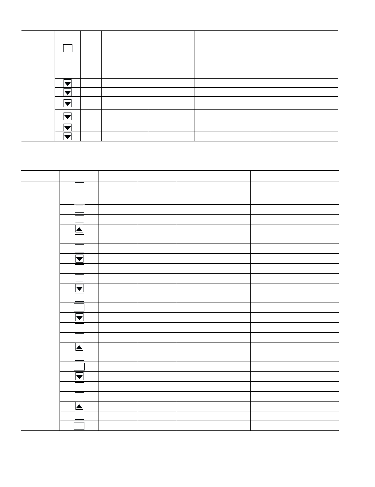
38
Table 16 — Configuration Mode and Sub-Mode Directory (cont)
Table 17 — Example of Temperature Reset (Return Fluid) Configuration
NOTE: The example above shows how to configure the chiller for temperature reset based on chiller return fluid. The
chiller will be configured for no reset at a cooler ∆T (EWT-LWT) of 10 F (5.6 C) and a full reset of 8 F (4.4 C) at a cooler ∆T
of 2 F (1.1 C).
SUB-MODE KEYPAD
ENTRY ITEM MARQUEE
DISPLAY RANGE
NAVIGATOR
DISPLAY RANGE ITEM EXPANSION COMMENT
SLCT CLSP 0 - 5 DUAL SWITCH
DUAL 7 DAY
DUAL CCN OCC
4-20 INPUT
EXTERNAL POT
COOLING SETPOINT
SELECT
Default: 0
0 = Single
1 = Dual Switch
2 = Dual 7 Day
3 = Dual CCN Occupancy
4 = 4-20 Input
5 = Set Point Potentiometer
HTSP 0 - 4 0 - 4 HEATING SETPOINT SELECT Not Supported
RL.S ENBL-DSBL ENBL-DSBL RAMP LOAD SELECT Default: DSBL
CRMP 0.2 - 2.0° F
(0.1 - 1.1° C)
0.2 - 2.0° F
(0.1 - 1.1° C) COOLING RAMP LOADING Default: 1.0
HRMP 0.2 - 2.0° F
(0.1 - 1.1° C)
0.2 - 2.0° F
(0.1 - 1.1° C) HEATING RAMP LOADING Not Supported
HCSW COOL-HEAT COOL-HEAT HEAT COOL SELECT Not Supported
Z.GN 1.0 - 4.0 1.0 - 4.0 DEADBAND MULTIPLIER Default: 1.0
SUB-MODE KEYPAD
ENTRY ITEM DISPLAY ITEM EXPANSION COMMENT
RSET CRST 0 COOLING RESET TYPE 0 = No reset
1 = 4 to 20 mA input
2 = Outdoor Air Temp
3 = Return Fluid
4 = Space Temperature
0Scrolling stops
0Value flashes
3Select 3
3Change accepted
CRST 3 Item/Value/Units scrolls again
CRT1 125 NO COOL RESET TEMP Range: 0° to 125 F
125 Scrolling stops
125 Value flashes
10 Select 10
10 Change accepted
CRT1 10 Item/Value/Units scrolls again
CRT2 0 FULL COOL RESET TEMP Range: 0° to 125 F
0Scrolling stops
0Value flashes
2Select 2
2Change accepted
CRT2 2 Item/Value/Units scrolls again
DGRC 0 DEGREES COOL RESET Range: –30 to 30 F
0Scrolling stops
0Value flashes
8Select 8
8Change accepted
DGRC 8 Item/Value/Units scrolls again
ENTER
ENTER
ENTER
ENTER
ENTER
ENTER
ENTER
ENTER
ENTER
ESCAPE
ENTER
ENTER
ENTER
ESCAPE
ENTER
ENTER
ENTER
ESCAPE
39
Table 18A — Example of Configuring Dual Chiller Control
(Master Chiller)
Table 18B — Example of Configuring Dual Chiller Control
(Slave Chiller)
SUB-MODE KEYPAD ENTRY ITEM DISPLAY ITEM EXPANSION COMMENT
RSET CRST 0 COOLING RESET TYPE
LLDY 5 LAG START DELAY
5Scrolling stops
5Value flashes
10 Select 10
10 Change accepted
LLDY 10
LLBD 168 LEAD/LAG BALANCE DELTA No change needed. Default set for weekly changeover
LLBL DSBL LEAD/LAG BALANCE SELECT
DSBL Scrolling stops
DSBL Value flashes
ENBL Select Enable
ENBL Change accepted
LLBL ENBL
SLVA 0 SLAVE ADDRESS
0Scrolling stops
0Value flashes
6Select 6
6Change accepted
SLVA 6
MSSL MAST MASTER/SLAVE SELECT No change needed. Default set for Master
SUB-MODE KEYPAD ENTRY ITEM DISPLAY ITEM EXPANSION COMMENT
RSET CRST 0 COOLING RESET TYPE
LLDY 5 LAG START DELAY
LLBD 168 LEAD/LAG BALANCE DELTA No change needed. Default set for weekly changeover
LLBL DSBL LEAD/LAG BALANCE SELECT
SLVA 0 SLAVE ADDRESS
MSSL MAST MASTER/SLAVE SELECT Default set for Master
MAST Scrolling stops
MAST Value flashes
SLVE Select SLVE
SLVE Change accepted
MSSL Item/Value/Units scrolls again
LLEN DSBL LEAD/LAG CHILLER ENABLE
DSBL Scrolling stops
DSBL Value flashes
ENBL Select enable
LLEN ENBL Change accepted
LLEN ENBL LEAD/LAG CHILLER ENABLE Item/Value/Units scrolls again
ENTER
ENTER
ENTER
ENTER
ESCAPE
ENTER
ENTER
ENTER
ESCAPE
ENTER
ENTER
ENTER
ESCAPE
ENTER
ENTER
ENTER
ENTER
ENTER
ENTER
ENTER
ESCAPE
40
Table 19 — Example of Compressor Lead/Lag Configuration
NOTE: Options 1 and/or 3 not valid for sizes 040-070 without Circuit B accessory unloader installed.
Table 20 — Time Clock Mode and Sub-Mode Directory
SUB-MODE KEYPAD
ENTRY ITEM DISPLAY ITEM EXPANSION COMMENT
OPT2 CTRL 0 CONTROL METHOD
CCNA 1
CCNB 0
BAUD 3
LOAD 1
LLCS 1 LEAD/LAG CIRCUIT SELECT
DEFAULT: 1 (Size 080-420)
2 (Size 040-070)
1 = Automatic
2 = Circuit A Leads
3 = Circuit B Leads
1 Scrolling stops
1 Value flashes
3 Select 3 (See note below)
3 Change accepted
LLCS 3 LEAD/LAG CIRCUIT SELECT Item/Value/Units scrolls again
SUB-MODE KEYPAD ENTRY ITEM ITEM
RANGE ITEM EXPANSION COMMENT
TIME HH.MM 00.00 - 23.59 HOUR AND MINUTE Military (00.00-23.59)
DATE MNTH 1 - 12 MONTH 1=Jan, 2=Feb, etc.
DOM 1 - 31 DATE OF MONTH
DAY 1 - 7 DAY OF WEEK 1=Mon, 2=Tue, etc.
YEAR 0000 - 9999 YEAR OF CENTURY
SCHD MON.O 00.00 - 23.59 MONDAY OCCUPIED TIME Default: 00.00
MON.U 00.00 - 23.59 MONDAY UNOCCUPIED TIME Default: 00.00
TUE.O 00.00 - 23.59 TUESDAY OCCUPIED TIME Default: 00.00
TUE.U 00.00 - 23.59 TUESDAY UNOCCUPIED TIME Default: 00.00
WED.O 00.00 - 23.59 WEDNESDAY OCCUPIED TIME Default: 00.00
WED.U 00.00 - 23.59 WEDNESDAY UNOCC TIME Default: 00.00
THU.O 00.00 - 23.59 THURSDAY OCCUPIED TIME Default: 00.00
THU.U 00.00 - 23.59 THURSDAY UNOCCUPIED TIME Default: 00.00
FRI.O 00.00 - 23.59 FRIDAY OCCUPIED TIME Default: 00.00
FRI.U 00.00 - 23.59 FRIDAY UNOCCUPIED TIME Default: 00.00
SAT.O 00.00 - 23.59 SATURDAY OCCUPIED TIME Default: 00.00
SAT.U 00.00 - 23.59 SATURDAY UNOCCUPIED TIME Default: 00.00
SUN.O 00.00 - 23.59 SUNDAY OCCUPIED TIME Default: 00.00
SUN.U 00.00 - 23.59 SUNDAY UNOCCUPIED TIME Default: 00.00
ENTER
ENTER
ENTER
ENTER
ESCAPE
ENTER
ENTER
ENTER
41
Table 21 — Setting an Occupied Time Schedule
Table 22 — Operating Mode and Sub-Mode Directory
LEGEND
SUB-MODE KEYPAD ENTRY ITEM DISPLAY ITEM EXPANSION COMMENT
SCHD MON.O 00.00 MONDAY OCCUPIED TIME TIME IN MILITARY FORMAT (HH.MM)
00.00 Scrolling stops
00.00 Hours flash
07.00 Select 7 AM
07.00 Change accepted, minutes flash
07.30 Select 30
07.30 Change accepted
MON.O 07.30 MONDAY OCCUPIED TIME Item/Value/Units scrolls again
SUB-MODE KEYPAD ENTRY ITEM RANGE ITEM EXPANSION COMMENT
MODE MD01 OFF-ON FSM CONTROLLING CHILLER
MD02 OFF-ON WSM CONTROLLING CHILLER
MD03 OFF-ON MASTER/SLAVE CONTROL
MD04 OFF-ON LOW SOURCE PROTECTION Not Supported
MD05 OFF-ON RAMP LOAD LIMITED
MD06 OFF-ON TIMED OVERRIDE IN EFFECT
MD07 OFF-ON LOW COOLER SUCTION TEMPA
MD08 OFF-ON LOW COOLER SUCTION TEMPB
MD09 OFF-ON SLOW CHANGE OVERRIDE
MD10 OFF-ON MINIMUM OFF TIME ACTIVE
MD11 OFF-ON LOW SUCTION SUPERHEAT A
MD12 OFF-ON LOW SUCTION SUPERHEAT B
MD13 OFF-ON DUAL SETPOINT
MD14 OFF-ON TEMPERATURE RESET
MD15 OFF-ON DEMAND LIMIT IN EFFECT
MD16 OFF-ON COOLER FREEZE PROTECTION
MD17 OFF-ON LO TMP COOL/HI TMP HEAT
MD18 OFF-ON HI TMP COOL/LO TMP HEAT
MD19 OFF-ON MAKING ICE
MD20 OFF-ON STORING ICE
MD21 OFF-ON HIGH SCT CIRCUIT A
MD22 OFF-ON HIGH SCT CIRCUIT B
FSM —Flotronic™ System Manager
SCT —Saturated Condensing Temperature
WSM —Water System Manager
ENTER
ENTER
ENTER
ENTER
ENTER
ESCAPE
ENTER

42
Table 23 — Operating Modes
MODE NO. ITEM EXPANSION DESCRIPTION
01 FSM CONTROLLING CHILLER Flotronic™ System Manager (FSM) is controlling the chiller.
02 WSM CONTROLLING CHILLER Water System Manager (WSM) is controlling the chiller.
03 MASTER/SLAVE CONTROL Lead/Lag Chiller control is enabled.
04 LOW SOURCE PROTECTION Not currently supported.
05 RAMP LOAD LIMITED Ramp load (pulldown) limiting in effect. In this mode, the rate at which leaving
fluid temperature is dropped is limited to a predetermined value to prevent
compressor overloading. See CRMP set point in the Set Point Select (SLCT)
section of the Configuration mode. The pulldown limit can be modified, if
desired, to any rate from 0.2° F to 2° F (0.1° to 1° C)/minute.
06 TIMED OVERRIDE IN EFFECT Timed override is in effect. This is a 1 to 4 hour temporary override of the
programmed schedule, forcing unit to Occupied mode. Override can be
implemented with unit under Local (Enable) or CCN control. Override
expires after each use.
07 LOW COOLER SUCTION TEMP A Circuit A capacity may be limited due to operation of this mode. Control will
attempt to correct this situation for up to 10 minutes before shutting the cir-
cuit down. The control may decrease capacity when attempting to correct
this problem. See Alarms and Alerts section for more information.
08 LOW COOLER SUCTION TEMP B Circuit B capacity may be limited due to operation of this mode. Control will
attempt to correct this situation for up to10 minutes before shutting the cir-
cuit down. The control may decrease capacity when attempting to correct
this problem. See Alarms and Alerts section for more information.
09 SLOW CHANGE OVERRIDE Slow change override is in effect. The leaving fluid temperature is close to
and moving towards the control point.
10 MINIMUM OFF TIME ACTIVE Chiller is being held off by Minutes Off Time (DELY) found under Options 2
(OPT2) section of Configuration mode.
11 LOW SUCTION SUPERHEAT A Circuit A capacity may be limited due to operation of this mode. Control will
attempt to correct this situation for up to 5 minutes before shutting the cir-
cuit down. See Alarms and Alerts section for more information.
12 LOW SUCTION SUPERHEAT B Circuit B capacity may be limited due to operation of this mode. Control will
attempt to correct this situation for up to 5 minutes before shutting the cir-
cuit down. See Alarms and Alerts section for more information.
13 DUAL SET POINT Dual set point mode is in effect. Chiller controls to CSP.1 during occupied
periods and CSP.2 during unoccupied periods. Both CSP.1 and CSP.2 are
located under COOL in the Set Point mode.
14 TEMPERATURE RESET Temperature reset is in effect. In this mode, chiller is using temperature
reset to adjust leaving fluid set point upward and is currently controlling to
the modified set point. The set point can be modified based on return fluid,
outdoor-air-temperature, space temperature, or 4 to 20 mA signal.
15 DEMAND LIMIT IN EFFECT Demand limit is in effect. This indicates that the capacity of the chiller
is being limited by demand limit control option. Because of this limitation,
the chiller may not be able to produce the desired leaving fluid temperature.
Demand limit can be controlled by switch inputs or a 4 to 20 mA signal.
16 COOLER FREEZE PROTECTION Cooler fluid temperatures are approaching the Freeze point (see Alarms
and Alerts section for definition). The chiller will be shut down when either
fluid temperature falls below the Freeze point.
17 LO TMP COOL/HI TMP HEAT Chiller is in Cooling mode and the rate of change of the leaving fluid is neg-
ative and decreasing faster than -0.5° F per minute. Error between leaving
fluid and control point exceeds fixed amount. Control will automatically
unload the chiller if necessary.
18 HI TMP COOL/LO TMP HEAT Chiller is in Cooling mode and the rate of change of the leaving fluid is positive
and increasing. Error between leaving fluid and control point exceeds fixed
amount. Control will automatically load the chiller if necessary to better match
the increasing load.
19 MAKING ICE Chiller is in an unoccupied mode and is using Ice Set Point 3 (CSP.3) to make
ice. The ice done input to the Energy Management Module (EMM) is open.
20 STORING ICE Chiller is in an unoccupied mode and is controlling to Cooling Set Point 2
(CSP.2). The ice done input to the Energy Management Module (EMM) is
closed.
21 HIGH SCT CIRCUIT A Chiller is in a cooling mode and the Saturated Condensing temperature read
by sensor T3 is greater than 140 F (60 C). No additional stages of capacity
will be added. Chiller may be unloaded if SCT continues to rise to avoid high-
pressure switch trips by reducing condensing temperature.
22 HIGH SCT CIRCUIT B Chiller is in a cooling mode and the Saturated Condensing temperature read
by sensor T4 is greater than 140 F (60 C). No additional stages of capacity
will be added. Chiller may be unloaded if SCT continues to rise to avoid high-
pressure switch trips by reducing condensing temperature.
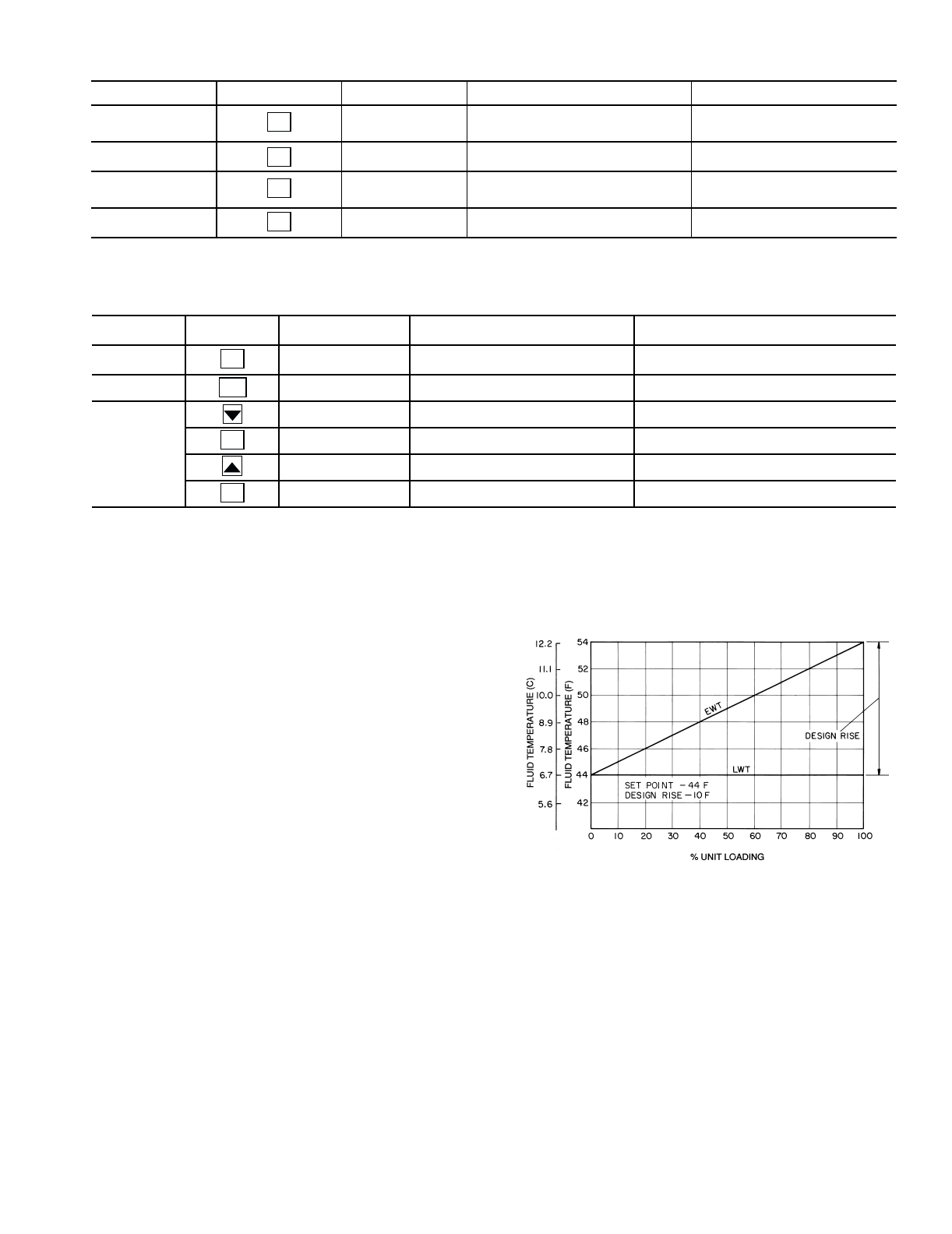
43
Table 24 — Alarms Mode and Sub-Mode Directory
Table 25 — Example of Reading and Clearing Alarms
Temperature Reset — The control system is capable of
handling leaving-fluid temperature reset based on return cooler
fluid temperature. Because the change in temperature through
the cooler is a measure of the building load, the return tempera-
ture reset is in effect an average building load reset method.
The control system is also capable of temperature reset based
on outdoor-air temperature (OAT), space temperature (SPT), or
from an externally powered 4 to 20 mA signal. Accessory sen-
sors must be used for OAT and SPT reset (HH79NZ073 for
OAT and HH51BX006 for SPT). The Energy Management
Module (EMM) must be used for temperature reset using a 4 to
20 mA signal.
To use the return reset, four variables must be configured. In
the Configuration mode under the sub-mode RSET, items
CRST, CRT1, CRT2, and DGRC must be set properly. See Ta-
ble 26 on page 44 for correct configuration. See Fig. 2-4 for
wiring details.
Under normal operation, the chiller will maintain a constant
leaving fluid temperature approximately equal to the chilled
fluid set point. As the cooler load varies, the entering cooler
fluid will change in proportion to the load as shown in Fig. 21.
Usually the chiller size and leaving-fluid temperature set point
are selected based on a full-load condition. At part load, the flu-
id temperature set point may be colder than required. If the
leaving fluid temperature was allowed to increase at part load,
the efficiency of the machine would increase.
Return temperature reset allows for the leaving temperature
set point to be reset upward as a function of the return fluid
temperature or, in effect, the building load.
SUB-MODE KEYPAD ENTRY ITEM ITEM EXPANSION COMMENT
CRNT AXXX or TXXX CURRENTLY ACTIVE ALARMS Alarms are shown as AXXX.
Alerts are shown as TXXX.
RCRN YES/NO RESET ALL CURRENT ALARMS
HIST AXXX or TXXX ALARM HISTORY Alarms are shown as AXXX.
Alerts are shown as TXXX.
RHIS YES/NO RESET ALARM HISTORY
ENTER
ENTER
ENTER
ENTER
SUB-MODE KEYPAD
ENTRY ITEM ITEM EXPANSION COMMENT
CRNT AXXX or TXXX CURRENTLY ACTIVE ALARMS ACTIVE ALARMS (AXXX) OR
ALERTS (TXXX) DISPLAYED.
CRNT
RCRN NO Use to clear active alarms/alerts
NO NO Flashes
YES Select YES
NO Alarms/alerts clear, YES changes to NO
ENTER
ESCAPE
ENTER
ENTER
LEGEND
Fig. 21 — Standard Chilled Fluid
Temperature Control — No Reset
EWT —Entering Water (Fluid) Temperature
LWT —Leaving Water (Fluid) Temperature
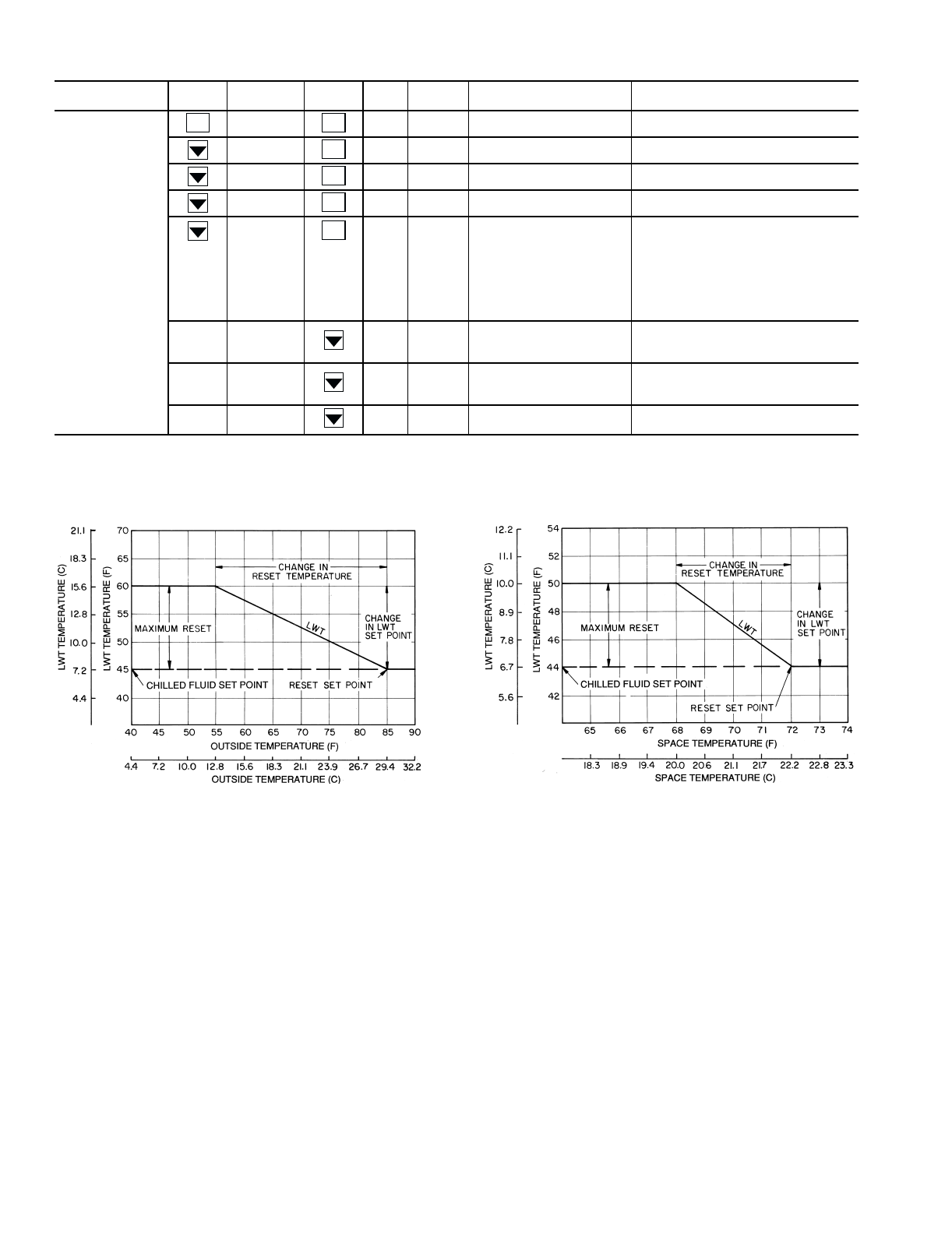
44
Table 26 — Configuring Temperature Reset
The following are examples of outdoor air and space tem-
perature resets:
MODE KEYPAD
ENTRY SUB-MODE KEYPAD
ENTRY ITEM DISPLAY ITEM
EXPANSION COMMENT
CONFIGURATION
DISP TEST ON/OFF TEST DISPLAY LEDS
UNIT TYPE UNIT TYPE
OPT1 FLUD COOLER FLUID
OPT2 CTRL CONTROL METHOD
RSET CRST COOLING RESET TYPE 0 = No Reset
1 = 4 to 20 mA Input (EMM required)
(Connect to EMM J6-2,5)
2 = Outdoor-Air Temperature
(Connect to TB5-7,8)
3 = Return Fluid
4 = Space Temperature (Connect to
TB5-5,6)
CRT1 XXX.X F NO COOL RESET TEMP
Default: 125 F (51.7 C)
Range: 0° to125 F
Set to 4.0 for CRST= 1
CRT2 XXX.X F FULL COOL RESET TEMP
Default: 0° F (–17.8 C)
Range: 0° to 125 F
Set to 20.0 for CRST=1
DGRC XX.X °F DEGREES COOL RESET Default: 0° F (0° C)
Range: –30 to 30° F (–16.7 to 16.7° C)
ENTER ENTER
ENTER
ENTER
ENTER
ENTER
LEGEND
LWT — Leaving Water (Fluid) Temperature
LEGEND
LWT — Leaving Water (Fluid) Temperature
45
Cooling Set Point (4 to 20 mA) — A field supplied
and generated, externally powered 4 to 20 mA signal can be
used to provide the leaving fluid temperature set point. Connect
the signal to TB6-3,5 (+,–). See Table 27 for instructions to
enable the function. Figure 22 shows how the 4 to 20 mA sig-
nal is linearly calculated on an overall 10 F to 80 F range for
fluid types (Configuration mode, sub-mode OPT1, item
FLUD) 1 or 2.
Table 27 — Menu Configuration of 4 to 20 mA Cooling Set Point Control
MODE
(RED LED)
KEYPAD
ENTRY SUB-MODE KEYPAD
ENTRY ITEM DISPLAY ITEM
EXPANSION COMMENT
CONFIGURATION DISP
UNIT
OPT1
OPT2
RSET
SLCT CLSP 0 COOLING SETPOINT SELECT
0 Scrolling Stops
0 Flashing ‘0’
4Select ‘4’
4 Change Accepted
ENTER
ENTER
ENTER
ENTER
ENTER
Fig. 22 — Cooling Set Point (4 to 20 mA)
EMM —Energy Management Module
100
(38)
80
(27)
60
(15)
40
(4.4)
20
(-7)
0
(-17) 4 6.3 8.6 10.9 13.1 15.4 17.7 20
4 TO 20 mA SIGNAL TO EMM
SET POINT, F (C)
46
Demand Limit — Demand Limit is a feature that allows
the unit capacity to be limited during periods of peak energy
usage. There are 3 types of demand limiting that can be config-
ured. The first type is through 2-stage switch control, which
will reduce the maximum capacity to 2 user-configurable per-
centages. The second type is by 4 to 20 mA signal input which
will reduce the maximum capacity linearly between 100% at a
4 mA input signal (no reduction) down to the user-configurable
level at a 20 mA input signal. The third type uses the CNN
Loadshed module and has the ability to limit the current operat-
ing capacity to maximum and further reduce the capacity if
required.
NOTE: The 2-stage switch control and 4 to 20 mA input signal
types of demand limiting require the Energy Management
Module (EMM).
To use Demand Limit, select the type of demand limiting to
use. Then configure the Demand Limit set points based on the
type selected.
DEMAND LIMIT (2-Stage Switch Controlled) — To con-
figure Demand Limit for 2-stage switch control set the
Demand Limit Select (DMDC) to 1. Then configure the 2 De-
mand Limit Switch points (DLS1 and DLS2) to the desired ca-
pacity limit. See Table 28. Capacity steps are controlled by
2 relay switch inputs field wired to TB6 as shown in Fig. 2-4.
For Demand Limit by 2-stage switch control, closing the
first stage demand limit contact will put the unit on the first de-
mand limit level. The unit will not exceed the percentage of ca-
pacity entered as Demand Limit Switch 1 set point. Closing
contacts on the second demand limit switch prevents the unit
from exceeding the capacity entered as Demand Limit Switch
2 set point. The demand limit stage that is set to the lowest de-
mand takes priority if both demand limit inputs are closed. If
the demand limit percentage does not match unit staging, the
unit will limit capacity to the closest capacity stage.
To disable demand limit configure the DMDC to 0. See
Table 28.
EXTERNALLY POWERED DEMAND LIMIT (4 to
20 mA Controlled) — To configure Demand Limit for 4 to
20 mA control set the Demand Limit Select (DMDC) to 2.
Then configure the Demand Limit at 20 mA (DM20) to the
maximum loadshed value desired. The control will reduce al-
lowable capacity to this level for the 20 mA signal. See
Table 28 and Fig. 23.
DEMAND LIMIT (CCN Loadshed Controlled) — To con-
figure Demand Limit for CCN Loadshed control set the De-
mand Limit Select (DMDC) to 3. Then configure the Loadshed
Group Number (SHNM), Loadshed Demand Delta (SHDL),
and Maximum Loadshed Time (SHTM). See Table 28.
The Loadshed Group number is established by the CCN
system designer. The MBB will respond to a Redline com-
mand from the Loadshed control. When the Redline command
is received, the current stage of capacity is set to the maximum
stages available. Should the loadshed control send a Loadshed
command, the MBB will reduce the current stages by the value
entered for Loadshed Demand delta. The Maximum Loadshed
Time defines the maximum length of time that a loadshed con-
dition is allowed to exist. The control will disable the Redline/
Loadshed command if no Cancel command has been received
within the configured maximum loadshed time limit.
Table 28 — Configuring Demand Limit
NOTE: Heating reset values skipped in this example.
MODE KEYPAD
ENTRY SUB-MODE KEYPAD
ENTRY ITEM DISPLAY ITEM EXPANSION COMMENT
CONFIGURATION DISP TEST ON/OFF Test Display LEDs
UNIT TYPE X Unit Type
OPT1 FLUD X Cooler Fluid
OPT2 CTRL X Control Method
RSET CRST X Cooling Reset Type
CRT1 XXX.X °F No Cool Reset Temperature
CRT2 XXX.X °F Full Cool Reset Temperature
DGRC XX.X ∆F Degrees Cool Reset
DMDC X Demand Limit Select
Default: 0
0 = None
1 = Switch
2 = 4 to 20 mA Input
3 = CCN Loadshed
DM20 XXX % Demand Limit at 20 mA Default: 100%
Range: 0 to 100
SHNM XXX Loadshed Group
Number
Default: 0
Range: 0 to 99
SHDL XXX% Loadshed Demand
Delta
Default: 0%
Range: 0 to 60%
SHTM XXX MIN Maximum Loadshed
Time
Default: 60 min.
Range: 0 to 120 min.
DLS1 XXX % Demand Limit
Switch 1
Default: 80%
Range: 0 to 100%
DLS2 XXX% Demand Limit
Switch 2
Default: 50%
Range: 0 to 100%
ENTER ENTER
ENTER
ENTER
ENTER
ENTER
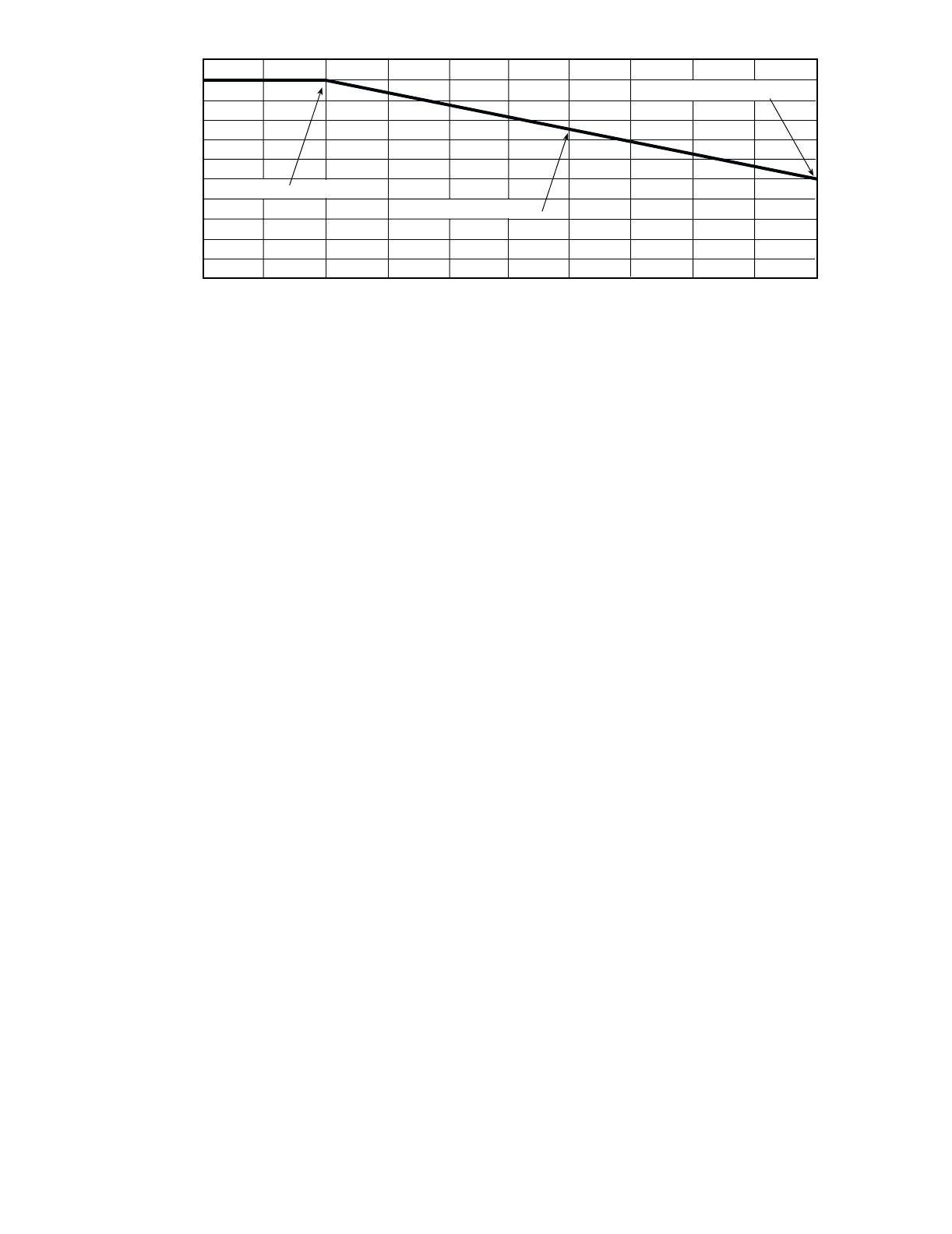
47
TROUBLESHOOTING
Compressor Protection Control System
(CPCS) Board — The compressor protection board con-
trols the compressor and compressor crankcase heater.
The ground current protection is provided by the compres-
sor board.
The large relay located on the board is used to provide a
feedback signal to the Main Base Board.
The operation of the compressor board can be checked us-
ing the Service Test procedure. When the Service Test step is
turned on, the compressor board is energized. All safeties are
continuously monitored. The crankcase heater will be turned
off and the compressor contactor will be turned on. The feed-
back contacts will close and the Main Base Board (MBB) will
read the feedback status.
If the board does not perform properly, use standard wiring
troubleshooting procedures to check the wiring for open cir-
cuits. Refer to Alarms and Alerts section on page 48 for alarm
or alert codes for possible causes for failure.
If a compressor short-to-ground exists, the compressor
board may detect the short before the circuit breaker trips. If
this is suspected, check the compressor for short-to-ground
failures with an ohmmeter. The ground current is sensed with a
current toroid (coil) around all 3 or 6 wires between the main
terminal block and the compressor circuit breaker(s).
Compressor Ground Current (CGF) Board
(30GTN,R and 30GUN,R 130-210, 230A-315A,
and 330A/B-420A/B) — One board is used for each cir-
cuit of these units. Each board receives input from up to 4 tor-
oids wired in series, one toroid per compressor. With 24 v sup-
plied at terminals A and B, a current imbalance (compressor
ground current) sensed by any toroid causes the NC (normally
closed) contacts to open, shutting down the lead compressor in
the affected circuit. All other compressors in that circuit shut
down as a result. The NC contacts remain open until the circuit
is reset by momentarily deenergizing the board using the push-
button switch.
If the NC contacts open, it is necessary to remove toroids
from the T1-T2 circuit to determine which toroid is causing the
trip. The chiller circuit can then be put back on line after the
circuit breaker of the faulty compressor is opened. The com-
pressor problem can then be diagnosed by normal trouble-
shooting procedures.
EXV Troubleshooting — If it appears that the EXV is
not properly controlling operating suction pressure or super-
heat, there are a number of checks that can be made using
the quick test and initialization features built into the
ComfortLink™ control.
Follow the procedure below to diagnose and correct EXV
problems.
STEP 1 — CHECK PROCESSOR EXV OUTPUTS —
Check EXV output signals at the J6 and J7 terminals of the
EXV board.
Turn unit power off. Connect the positive lead of the meter
to terminal 3 on connector J6 on the EXV board. Set meter for
approximately 20 vdc. Turn unit power on. Enter and enable
the Service Test mode. Locate the appropriate EXV under
‘OUTS.’ Select the desired percentage and press Enter to move
the valve. The valve will overdrive in both directions when
either 0% or 100% are entered. During this time, connect the
negative test lead to terminals 1, 2, 4, and 5 in succession. The
voltage should fluctuate at each pin. If it remains constant at a
voltage or at 0 v, replace the EXV board. If the outputs are cor-
rect, then check the EXV.
To test Circuit B outputs, follow the same procedure above,
except connect the positive lead of the meter to terminal 3 on
connector J7 on the EXV board and the negative lead to termi-
nals 1, 2, 4, and 5 in succession.
STEP 2 — CHECK EXV WIRING — Check wiring to
EXVs from J6 and J7 connectors on EXV board.
1. Check color coding and wire connections. Make sure
that wires are connected to correct terminals at J6 and
J7 connectors and EXV plug connections. Check for
correct wiring at driver board input and output termi-
nals. See Fig. 2-4.
2. Check for continuity and tight connection at all pin
terminals.
3. Check plug connections at J6 and J7 connectors and at
EXVs. Be sure EXV connections are not crossed.
STEP 3 — CHECK RESISTANCE OF EXV MOTOR
WINDINGS — Remove connector at J6 and/or J7 of EXV
board and check resistance between common lead (red wire,
terminal D) and remaining leads A, B, C, and E. Resistance
should be 25 ohms ± 2 ohms. Check all leads to ground for
shorts.
STEP 4 — CHECK THERMISTORS THAT CONTROL
EXV — Check thermistors that control processor output volt-
age pulses to the EXVs. Circuit A thermistor is T7, and circuit
B thermistor is T8. Refer to Fig. 9 and 10 for location.
1. Refer to Thermistors section on page 59 for details on
checking thermistor calibration.
50% CAPACITY AT 20 mA
75% CAPACITY AT 12 mA
100% CAPACITY AT 4 mA
0 2 4 6810 12 14 16 18 20
DEMAND LIMIT SIGNAL – 4 - 20 mA INPUT (VOLTS DC)
100
80
60
40
20
0
MAX. ALLOWABLE LOAD (%)
Fig. 23 — 4 to 20 mA Demand Limiting
48
2. Make sure that thermistor leads are connected to the
proper pin terminals at the J5 connector on EXV board
and that thermistor probes are located in proper position
in the refrigerant circuit.
When these checks have been completed, the actual opera-
tion of the EXV can be checked by using the procedures out-
lined in Step 5 — Check Operation of the EXV section below.
STEP 5 — CHECK OPERATION OF THE EXV — Use
the following procedure to check the actual operation of the
EXVs. The ENABLE/OFF/REMOTE contact switch must be
in the OFF position.
1. Close the liquid line service valve for the circuit to be
checked and run through the appropriate service test to
pump down the low side of the system. Run lead com-
pressor for at least 30 seconds to ensure all refrigerant
has been pumped from the low side and that the EXV
has been driven fully open (1500 steps).
NOTE: Do not use the Emergency ON-OFF switch to
recycle the control during this step.
2. Turn off the compressor circuit breaker(s) and the control
circuit power and then turn the Emergency ON/OFF
switch to the OFF position. Close compressor service
valves and remove any remaining refrigerant from the
low side of the system.
3. Carefully loosen the 2-1/8 in. nut. Do not twist the valve.
Remove the motor canister from the valve body using
caution to avoid damage to the o-ring seal. If the EXV
plug was disconnected during this process reconnect it
after the motor canister is removed.
4. Note position of lead screw (see Fig. 15). If valve has re-
sponded properly to processor signals in Step 5.1 above,
the lead screw should be fully retracted.
5. Recycle the control by turning the Emergency ON-OFF
switch to the ON position. This puts the control in initial-
ization mode. During the first 60 seconds of the initializa-
tion mode, each valve is driven to the fully closed posi-
tion (1500 steps) by the processor. Observe the move-
ment of the lead screw. It should be smooth and uniform
from the fully retracted (open) to the fully extended
(closed) position.
6. When the test has been completed, carefully reassemble
expansion valve. Apply a small amount of O-ring grease
to the housing seal O-ring before installing the motor can-
ister. Be careful not to damage the O-ring. Tighten the
motor nut to 15 to 25 lb-ft (20 to 34 N-m). Evacuate the
low side of the open refrigerant circuit. Open compressor
service valves and close compressor circuit breakers.
Open liquid line service valve. Check for any refrigerant
leaks. Turn the ENABLE/OFF/REMOTE switch back to
ENABLE or REMOTE and allow the unit to operate.
Verify proper unit operation.
NOTE: The EXV orifice is a screw-in type and may be
removed for inspection and cleaning. Once the motor canister
is removed the orifice can be removed by using the orifice
removal tool (part no. TS429). A slot has been cut in the top of
the orifice to facilitate removal. Turn orifice counterclockwise
to remove. A large screwdriver may also be used.
When cleaning or reinstalling orifice assembly be careful
not to damage orifice assembly seals. The bottom seal acts as a
liquid shut-off, replacing a liquid line solenoid valve. If the bot-
tom seal should become damaged it can be replaced. Remove
the orifice. Remove the old seal. Using the orifice as a guide,
add a small amount of O-ring grease, to the underside of the or-
ifice. Be careful not to plug the vent holes. Carefully set the
seal with the O-ring into the orifice. The O-ring grease will
hold the seal in place. If the O-ring grease is not used, the seal
O-ring will twist and bind when the orifice is screwed into the
EXV base. Install the orifice and seal assembly. Remove the
orifice to verify that the seal is properly positioned. Clean any
O-ring grease from the bottom of the orifice. Reinstall the ori-
fice and tighten to 100 in.-lb (11 N-m). Apply a small amount
of O-ring grease to the housing seal O-ring before installing the
motor canister. Reinstall the motor canister assembly. Tighten
the motor nut to 15 to 25 ft-lb (20 to 34 N-m).
Alarms and Alerts — These are warnings of abnormal
or fault conditions, and may cause either one circuit or the
whole unit to shut down. They are assigned code numbers as
described in Table 29.
Automatic alarms will reset without operator intervention if
the condition corrects itself. The following method must be
used to reset manual alarms:
Before resetting any alarm, first determine the cause of the
alarm and correct it. Enter the Alarms mode indicated by the
LED on the side of the Scrolling Marquee Display. Press
and until the sub-menu item RCRN “RESET
ALL CURRENT ALARMS” is displayed. Press .
The control will prompt the user for a password, by displaying
PASS and WORD. Press to display the default pass-
word, 1111. Press for each character. If the password
has been changed, use the arrow keys to change each individu-
al character. Toggle the display to “YES” and press .
The alarms will be reset.
ENTER
ENTER
ENTER
ENTER
ENTER

49
Table 29 — Alarm and Alert Codes
ALARM/
ALERT
CODE
ALARM
OR
ALERT
DESCRIPTION
WHY WAS THIS
ALARM
GENERATED?
ACTION TAKEN
BY CONTROL
RESET
METHOD
PROBABLE
CAUSE
T051 Alert Circuit A, Compressor 1
Failure
Compressor feedback signal
does not match relay state
Circuit A shut down. Manual High-pressure or loss-of-
charge switch open, faulty
control relay or CPCS board,
loss of condenser air, liquid
valve closed, operation
beyond capability.
T052 Alert Circuit A, Compressor 2
Failure
Compressor feedback signal
does not match relay state
Circuit A shut down. Circuit
restarted in 1 minute. Com-
pressor A2 not used until
alarm is reset.
Manual High-pressure switch open,
faulty control relay or CPCS
board, loss of condenser air,
liquid valve closed, opera-
tion beyond capability.
T053 Alert Circuit A, Compressor 3
Failure
Compressor feedback signal
does not match relay state
Circuit A shut down. Circuit
restarted in 1 minute. Com-
pressor A3 not used until
alarm is reset.
Manual High-pressure switch open,
faulty control relay or CPCS
board, loss of condenser air,
liquid valve closed, opera-
tion beyond capability.
T054 Alert Circuit A, Compressor 4
Failure
Compressor feedback signal
does not match relay state
Circuit A shut down. Circuit
restarted in 1 minute. Com-
pressor A4 not used until
alarm is reset.
Manual High-pressure switch open,
faulty control relay or CPCS
board, loss of condenser air,
liquid valve closed, opera-
tion beyond capability.
T055 Alert Circuit B, Compressor 1
Failure
Compressor feedback signal
does not match relay state
Circuit B shut down. Manual High-pressure or loss-of-
charge switch open, faulty
control relay or CPCS board,
loss of condenser air, liquid
valve closed, operation
beyond capability.
T056 Alert Circuit B, Compressor 2
Failure
Compressor feedback signal
does not match relay state
Circuit B shut down. Circuit
restarted in 1 minute. Com-
pressor B2 not used until
alarm is reset.
Manual High-pressure switch open,
faulty control relay or CPCS
board, loss of condenser air,
liquid valve closed, opera-
tion beyond capability.
T057 Alert Circuit B, Compressor 3
Failure
Compressor feedback signal
does not match relay state
Circuit B shut down. Circuit
restarted in 1 minute. Com-
pressor B3 not used until
alarm is reset.
Manual High-pressure switch open,
faulty control relay or CPCS
board, loss of condenser air,
liquid valve closed, opera-
tion beyond capability.
A060 Alarm Cooler Leaving Fluid
Thermistor Failure (T1)
Thermistor outside range of
–40 to 245 F (–40 to 118 C)
Chiller shutdown after
pumpdown complete.
Automatic Thermistor failure, damaged
cable/wire or wiring error.
A061 Alarm Cooler Entering Fluid
Thermistor Failure (T2)
Thermistor outside range of
–40 to 245 F (–40 to 118 C)
Chiller shutdown after
pumpdown complete.
Automatic Thermistor failure, damaged
cable/wire or wiring error.
T064 Alert Circuit A Saturated Con-
densing Thermistor Failure
(T3)
Thermistor outside range of
–40 to 245 F (–40 to 118 C)
Circuit A shutdown after
pumpdown complete.
Automatic Thermistor failure, damaged
cable/wire or wiring error.
T065 Alert Circuit B Saturated Con-
densing Thermistor Failure
(T4)
Thermistor outside range of
–40 to 245 F (–40 to 118 C)
Circuit B shutdown after
pumpdown complete.
Automatic Thermistor failure, damaged
cable/wire or wiring error.
T066 Alert Circuit A Saturated Suction
Thermistor Failure (T5)
Thermistor outside range of
–40 to 245 F (–40 to 118 C)
Circuit A shutdown after
pumpdown complete.
(EXV only)
Automatic Thermistor failure, damaged
cable/wire or wiring error.
T067 Alert Circuit B Saturated Suction
Thermistor Failure (T6)
Thermistor outside range of
–40 to 245 F (–40 to 118 C)
Circuit B shutdown after
pumpdown complete.
(EXV only).
Automatic Thermistor failure, damaged
cable/wire or wiring error.
T068 Alert Compressor A1 Suction
Gas Thermistor Failure (T7)
Thermistor outside range of
–40 to 245 F (–40 to 118 C)
Circuit A shutdown after
pumpdown complete.
(EXV only).
Automatic Thermistor failure, damaged
cable/wire or wiring error.
T069 Alert Compressor B1 Suction
Gas Thermistor Failure (T8)
Thermistor outside range of
–40 to 245 F (–40 to 118 C)
Circuit B shutdown after
pumpdown complete.
(EXV only).
Automatic Thermistor failure, damaged
cable/wire or wiring error.
T073 Alert Outside Air Thermistor
Failure (T9)
Thermistor outside range of
–40 to 245 F (–40 to 118 C)
Temperature reset disabled.
Chiller runs under normal
control/set points.
Automatic Thermistor failure, damaged
cable/wire or wiring error.
T074 Alert Space Temperature
Thermistor Failure (T10)
Thermistor outside range of
–40 to 245 F (–40 to 118 C)
Temperature reset disabled.
Chiller runs under normal
control/set points.
Automatic Thermistor failure, damaged
cable/wire or wiring error.
T077 Alert Circuit A Saturated
Suction Temperature
exceeds Cooler Leaving
Fluid Temperature
Saturated suction is
greater than leaving fluid
temperature for more than
5 minutes
Circuit A shutdown after
pumpdown complete.
Automatic Faulty expansion valve or
EXV board, faulty cooler suc-
tion thermistor (T5) or leav-
ing fluid thermistor (T1).
T078 Alert Circuit B Saturated
Suction Temperature
exceeds Cooler Leaving
Fluid Temperature
Saturated suction is
greater than leaving fluid
temperature for more than
5 minutes
Circuit B shutdown after
pumpdown complete
Automatic Faulty expansion valve or
EXV board, faulty cooler suc-
tion thermistor (T6) or leav-
ing fluid thermistor (T1).
T079 Alert Lead/Lag Thermistor Failure Thermistor outside range of
–40 to 245 F (–40 to 118 C)
Lead/lag algorithm runs
using Master LWT sensor
Master is lead chiller.
Automatic Dual chiller LWT thermistor
failure, damaged cable/wire
or wiring error.
50
Table 29 — Alarm and Alert Codes (cont)
LEGEND *Freeze is defined as 34° F (1.1 C) for water. For brine fluids, freeze
is CSP.1 –8° F (4.4 C) for single set point and lower of CSP.1 or
CSP.2 –8° F (4.4 C) for dual set point configuration.
ALARM/
ALERT
CODE
ALARM
OR
ALERT
DESCRIPTION
WHY WAS THIS
ALARM
GENERATED?
ACTION TAKEN
BY CONTROL
RESET
METHOD
PROBABLE
CAUSE
T112 Alert Circuit A High Suction
Superheat
If EXV is greater than
98%, suction superheat is
greater than 75 F (41.7 C)
and saturated suction
temperature is less than
MOP for 5 minutes
Circuit A shutdown after
pumpdown complete.
Manual Faulty expansion
valve or EXV board,
low refrigerant
charge, plugged fil-
ter drier, faulty suc-
tion gas thermistor
(T7) or cooler ther-
mistor (T5).
T113 Alert Circuit B High Suction
Superheat
If EXV is greater than
98% suction superheat is
greater than 75 F (41.7 C)
and saturated suction
temperature is less than
MOP for 5 minutes
Circuit B shutdown after
pumpdown complete.
Manual Faulty expansion
valve or EXV board,
low refrigerant
charge, plugged fil-
ter drier, faulty suc-
tion gas thermistor
(T8) or cooler ther-
mistor (T6).
T114 Alert Circuit A Low Suction
Superheat
If EXV is greater than
10%, and either suction
superheat is less than
superheat set point –10 F
(5.6 C) or saturated
suction temperature is
greater than MOP for
5 minutes
Circuit A shutdown after
pumpdown complete.
Automatic restart
after first daily
occurrence.
Manual restart
thereafter.
Faulty expansion
valve or EXV board,
faulty suction gas
thermistor (T7) or
cooler thermistor
(T5).
T115 Alert Circuit B Low Suction
Superheat
If EXV is greater than
10%, and either suction
superheat is less than
superheat set point –10 F
(5.6 C) or saturated
suction temperature is
greater than MOP for
5 minutes
Circuit B shutdown after
pumpdown complete.
Automatic restart
after first daily
occurrence.
Manual restart
thereafter.
Faulty expansion
valve or EXV board,
faulty suction gas
thermistor (T8) or
cooler thermistor
(T6).
T116 Alert Circuit A Low Cooler
Suction Temperature
1. If the saturated suction
temperature is 24 to
29° F (13.3 to 16.1° C)
below cooler LWT and
is also 2° F (1.1° C)
less than freeze*
2. If the saturated suction
temperature is 30° F
(16.7° C) below cooler
LWT and is also 2° F
(1.1° C) less than
freeze* for 10 minutes
1. Mode 7 initiated. No addi-
tional capacity increases.
Alert not tripped.
2. Circuit shutdown without
going through pumpdown.
1. Automatic reset
if corrected.
2. Manual
Faulty expansion
valve or EXV board,
low refrigerant
charge, plugged fil-
ter drier, faulty suc-
tion gas thermistor
(T7) or cooler ther-
mistor (T5), low
cooler fluid flow.
T117 Alert Circuit B Low Cooler
Suction Temperature
1. If the saturated suction
temperature is 24 to
29°F (13.3 to 16.1° C)
below cooler LWT and
is also 2°F (1.1° C)
less than freeze*
2. If the saturated suction
temperature is 30° F
(16.7° C) below cooler
LWT and is also 2° F
(1.1° C) less than
freeze* for 10 minutes
1. Mode 8 initiated. No addi-
tional capacity increases.
Alert not tripped.
2. Circuit shutdown without
going through pumpdown.
1. Automatic reset
if corrected.
2. Manual
Faulty expansion
valve or EXV board,
low refrigerant
charge, plugged fil-
ter drier, faulty suc-
tion gas thermistor
(T8) or cooler ther-
mistor (T6), low
cooler fluid flow.
T118 Alert Circuit A Low Oil
Pressure
Oil pressure switch open
after 1 minute of continu-
ous operation
Circuit shutdown without
going through pumpdown.
Manual Oil pump failure, low
oil level, switch fail-
ure or compressor
circuit breaker
tripped.
T119 Alert Circuit B Low Oil
Pressure
Oil pressure switch open
after 1 minute of continu-
ous operation
Circuit shutdown without
going through pumpdown.
Manual Oil pump failure, low
oil level, switch fail-
ure or compressor
circuit breaker
tripped.
CCN —Carrier Comfort Network
CPCS —Compressor Protection Control System
CXB —Compressor Expansion Board
EMM —Energy Management Module
EWT —Entering Fluid Temperature
EXV —Electronic Expansion Valve
FSM —Flotronic™ System Manager
LCW —Leaving Chilled Water
LWT —Leaving Fluid Temperature
MBB —Main Base Board
MOP —Maximum Operating Pressure
WSM —Water System Manager

51
Table 29 — Alarm and Alert Codes (cont)
ALARM/
ALERT
CODE
ALARM
OR
ALERT
DESCRIPTION
WHY WAS THIS
ALARM
GENERATED?
ACTION TAKEN
BY CONTROL
RESET
METHOD
PROBABLE
CAUSE
A150 Alarm Emergency Stop CCN emergency stop
command received
Chiller shutdown
without going
through pumpdown.
Automatic once
CCN command for
EMSTOP returns
to normal
CCN Network
command.
A151 Alarm Illegal Configuration One or more of the ille-
gal configurations
exists.
Chiller is not
allowed to start.
Manual once con-
figuration errors
are corrected
Configuration
error. See Note on
page 52.
A152 Alarm Unit Down Due to
Failure
Both circuits are down
due to alarms/alerts.
Chiller is unable
to run.
Automatic once
alarms/alerts are
cleared that pre-
vent the chiller
from starting.
Alarm notifies user
that chiller is100%
down.
T153 Alert Real Time Clock
Hardware Failure
Internal clock on MBB
fails
Occupancy sched-
ule will not be used.
Chiller defaults to
Local On mode.
Automatic when
correct clock con-
trol restarts.
Time/Date/Month/
Day/Year not prop-
erly set.
A154 Alarm Serial EEPROM
Hardware Failure
Hardware failure with
MBB
Chiller is unable
to run.
Manual Main Base Board
failure.
T155 Alert Serial EEPROM
Storage Failure
Configuration/storage
failure with MBB
No Action Manual Potential failure of
MBB. Download
current operating
software. Replace
MBB if error
occurs again.
A156 Alarm Critical Serial
EEPROM Storage
Failure
Configuration/storage
failure with MBB
Chiller is not
allowed to run.
Manual Main Base Board
failure.
A157 Alarm A/D Hardware
Failure
Hardware failure with
peripheral device
Chiller is not
allowed to run.
Manual Main Base Board
failure.
T170 Alert Loss of Communica-
tion with CXB
MBB loses communica-
tion with CXB
Compressors A3,
A4 and B3 and
unloaders A2/B2
unable to operate.
Automatic Wiring error, faulty
wiring or failed
CXB module.
A172 Alarm Loss of Communica-
tion with EXV
MBB loses communica-
tion with EXV
Chiller shutdown
without going
through pumpdown.
Automatic Wiring error, faulty
wiring or failed
EXV module.
T173 Alert Loss of Communica-
tion with EMM
MBB loses communica-
tion with EMM
4 to 20 mA tempera-
ture reset disabled.
Demand Limit set to
100%. 4 to 20 mA
set point disabled.
Automatic Wiring error, faulty
wiring or failed
Energy Manage-
ment Module
(EMM).
T174 Alert 4 to 20 mA Cooling
Set Point Input Fail-
ure
If configured with EMM
and input less than
2 mA or greater than
22 mA
Set point function
disabled. Chiller
controls to CSP.1.
Automatic Faulty signal gen-
erator, wiring
error, or faulty
EMM.
T176 Alert 4 to 20 mA Tempera-
ture Reset Input
Failure
If configured with EMM
and input less than
2 mA or greater than
22 mA
Reset function dis-
abled. Chiller
returns to normal
set point control.
Automatic Faulty signal gen-
erator, wiring
error, or faulty
EMM.
T177 Alert 4 to 20 mA Demand
Limit Input Failure
If configured with EMM
and input less than
2 mA or greater than
22 mA
Demand limit func-
tion disabled. Chiller
returns to 100%
demand limit
control.
Automatic Faulty signal gen-
erator, wiring
error, or faulty
EMM.
A200 Alarm Cooler Pump Inter-
lock Failure to Close
at Start-Up
Interlock not closed
within 5 minutes after
unit is started
Cooler pump shut
off. Chiller shutdown
without going
through pumpdown.
Manual Failure of cooler
pump, flow switch,
or interlock.
A201 Alarm Cooler Pump Inter-
lock Opened During
Normal Operation
Interlock opens during
operation
Cooler pump shut
off. Chiller shutdown
without going
through pumpdown.
Manual Failure of cooler
pump, flow switch,
or interlock.
A202 Alarm Cooler Pump Inter-
lock Closed When
Pump is Off
If configured for cooler
pump control and inter-
lock closes while cooler
pump relay is off
Chiller is not
allowed to start.
Manual Failure of cooler
pump relay or
interlock, welded
contacts.
52
Table 29 — Alarm and Alert Codes (cont)
LEGEND
*Freeze is defined as 34° F (1.1 C) for water. For brine fluids, freeze
is CSP.1 –8° F (4.4 C) for single set point and lower of CSP.1 or
CSP.2 –8° F (4.4 C) for dual set point configuration.
NOTE: The following table shows illegal configurations:
ALARM/
ALERT
CODE
ALARM
OR
ALERT
DESCRIPTION
WHY WAS THIS
ALARM
GENERATED?
ACTION TAKEN
BY CONTROL
RES
METHOD
PROBABLE
CAUSE
T203 Alert Loss of Communica-
tion with Slave Chiller
Master MBB loses
communication with
Slave MBB
Dual chiller control dis-
abled. Chiller runs as a
stand-alone machine.
Automatic Wiring error, faulty wir-
ing, failed Slave MBB
module, power loss at
Slave chiller, wrong
slave address.
T204 Alert Loss of Communica-
tion with Master Chiller
Slave MBB loses com-
munication with Master
MBB
Dual chiller control dis-
abled. Chiller runs as a
stand-alone machine
Automatic Wiring error, faulty wir-
ing, failed Master MBB
module, power loss at
Master chiller.
T205 Alert Master and Slave
Chiller with Same
Address
Master and slave chiller
have the same CCN
address (CCN.A)
Dual chiller routine dis-
abled. Master/slave run
as stand-alone chillers.
Automatic CCN Address for both-
chillers is the same.
Must be different.
Check CCN.A under
the OPT2 sub-mode in
configuration at both
chillers.
T206 Alert High Leaving Chilled
Water Temperature
LWT read is greater
than LCW Alert Limit,
plus control point and
Total capacity is 100%
and LWT is greater
than LWT reading one
minute ago
Alert only. No action
taken.
Automatic Building load greater
than unit capacity, low
water/brine flow or
compressor fault.
Check for other
alarms/alerts.
A207 Alarm Cooler Freeze
Protection
Cooler EWT or LWT is
less than freeze*
Chiller shutdown with-
out going through
pumpdown. Cooler
pump continues to run
(if control enabled).
Automatic for
first occurrence
of day. Manual
reset thereafter.
Faulty thermistor (T1/
T2), low water flow.
A208 Alarm Low Cooler Fluid Flow Cooler EWT is less
than LWT by 3° F
(1.7° C) for 1 minute
after a circuit is started
Chiller shutdown with-
out going through
pumpdown. Cooler
pump shut off (if control
enabled).
Manual Faulty cooler pump,
low water flow, plugged
fluid strainer.
T950 Alert Loss of Communica-
tion with WSM
No communications
have been received by
MBB within 5 minutes
of last transmission
WSM forces removed.
Chiller runs under own
control.
Automatic Failed module, wiring
error, failed trans-
former, loose connec-
tion plug, wrong
address.
T951 Alert Loss of Communica-
tion with FSM
No communications
have been received by
MBB within 5 minutes
of last transmission
FSM forces removed.
Chiller runs under own
control.
Automatic Failed module, wiring
error, failed trans-
former, loose connec-
tion plug, wrong
address.
CCN —Carrier Comfort Network
CPCS —Compressor Protection Control System
CXB —Compressor Expansion Board
EMM —Energy Management Module
EXV —Electronic Expansion Valve
FSM —Flotronic™ System Manager
LCW —Leaving Chilled Water
LWT —Leaving Fluid Temperature
MBB —Main Base Board
MOP —Maximum Operating Pressure
WSM —Water System Manager
1Unit type = 0.
24 Compressors in a circuit with 2 unloaders.
34 Compressors in a circuit with 1 unloader and hot gas
bypass.
42 Unloaders and hot gas bypass in a circuit.
5More than one compressor difference between circuits (e.g., 4
compressors in Ckt A, 2 in Ckt B).
6Water cooled units with optional thermistors and configured
for head pressure control.
7Split system chillers with optional thermistors and configured
for head pressure control.
8Low temperature brine selected for air cooled chillers or split
systems with air cooled head pressure control.
9Water cooled unit configured for air cooled head pressure
control.
10
Air cooled head pressure control with common fan staging
and different head pressure control methods for each circuit
(EXV controlled vs. set point controlled).
11 Lead/lag enabled, Master selected and Cooling Set Point
select is LWT POT.
12 Water cooled or split units (units types 2, 3, 4) with more than
one compressor on a circuit.
13 Condenser pump interlock enabled on air cooled unit.
14 Unit type changed.
15 Low pressure set points out of range.
16 Cooler fluid type is water and ice mode is enabled.
53
SERVICE
Electronic Components
CONTROL COMPONENTS — Unit uses an advanced elec-
tronic control system that normally does not require service.
For details on controls refer to Operating Data section.
30GTN,R AND 30GUN,R 040-110, AND 230B-315B
UNIT CONTROL BOX — When facing compressors, main
control box is at left end of unit. All incoming power enters
through main box. Control box contains power components
and electronic controls.
Outer panels are hinged and latched for easy opening. Re-
move screws to remove inner panels. Outer panels can be held
open for service and inspection by using door retainer on each
panel. To use door retainers: remove bottom pin from door re-
tainer assembly, swing retainer out horizontally, and engage pin
in one of the retainer ears and the hinge assembly.
30GTN,R AND 30GUN,R 130-210, 230A-315A, AND
330A/B-420A/B UNIT CONTROL AND MAIN POWER
BOXES — The main power box is on the cooler side of the
unit, and the control box is on the compressor side. Outer pan-
els are hinged and latched for easy opening. Remove screws to
remove inner panels.
Compressors — If lead compressor on either refrigerant
circuit becomes inoperative for any reason, circuit is locked off
and cannot be operated due to features built into the electronic
control system. Do not attempt to bypass controls to force com-
pressors to run.
COMPRESSOR REMOVAL — Access to the oil pump end
of the compressor is from the compressor side of the unit. Ac-
cess to the motor end of the compressor is from the inside of
the unit. All compressors can be removed from the compressor
side of the unit.
Following the installation of the new compressor:
OIL CHARGE (Refer to Table 30) — All units are factory
charged with oil. Acceptable oil level for each compressor is
from 1/8 to 3/8-in. of sight glass (see Fig. 35).
When additional oil or a complete charge is required, use
only Carrier-approved compressor oil.
30GTN,R approved oils are as follows:
Petroleum Specialties, Inc. — Cryol 150 (factory oil charge)
Texaco, Inc. — Capella WF-32
Witco Chemical Co. — Suniso 3GS
30GUN,R approved polyolester (POE) oils are as follows:
•Mobil Artic EAL 68
•Castrol SW68
•ICI Emkarate RL68H
•Lubrizol 29168 (Texaco HFC Capella 68NA)
•CPI Solest 68
Table 30 — Oil Charge
Do not reuse drained oil or any oil that has been exposed to
atmosphere.
Cooler — The cooler is easily accessible from the cooler
side of the unit. The refrigerant feed components are accessible
from the control box end of the unit.
COOLER REMOVAL — Cooler can be removed from the
cooler side of the unit as follows:
1. To ensure the refrigerant is in the condenser, follow
this procedure:
a. Open the circuit breakers and close the discharge
valves for the lag compressors in both circuits.
b. After the lag compressor discharge service valves
have been closed, close the liquid line service
valve for one circuit. Allow the lead compressor to
pump down that circuit until it reaches approxi-
mately 10 to 15 psig (68.8 to 103.2 kPa).
c. As soon as the system reaches that pressure, shut
down the lead compressor by opening the com-
pressor circuit breaker, then quickly close the dis-
charge service valve for that compressor.
d. Repeat the procedure for the other circuit.
2. Close the shutoff valves, if installed, in the cooler fluid
lines. Remove the cooler fluid piping.
3. Cooler may be under pressure. Open the air vent at the
top of the cooler, and open the drain on the bottom of the
cooler (near the leaving fluid outlet) to drain the cooler.
Both the drain and the air vent are located on the leaving
fluid end of cooler. See Fig. 24. Remove the cooler water-
side strainer.
4. Disconnect the conduit and cooler heater wires, if
equipped. Remove all thermistors from the cooler, being
sure to label all thermistors as they are removed. Ther-
mistor T1 is a well-type thermistor, and thermistor T2 is
immersed directly in the fluid. See Fig. 24.
5. Remove the insulation on the refrigerant connection end
of the cooler.
6. Unbolt the suction flanges from the cooler head. Save the
bolts.
ELECTRIC SHOCK HAZARD.
Turn off all power to unit before servicing.
The ENABLE/OFF/REMOTE CONTACT
switch on control panel does not shut off con-
trol power; use field disconnect.
IMPORTANT: All compressor mounting hardware and
support brackets removed during servicing must be rein-
stalled prior to start-up.
Tighten discharge valves to —Compressor(s)
20 to 25 ft-lb (27 to 34 N-m) 06E250
80 to 90 ft-lb (109 to 122 N-m) 06E265,275,299
Tighten suction valves to —
80 to 90 ft-lb (109 to 122 N-m) 06E250
90 to 120 ft-lb (122 to 163 N-m) 06E265,275,299
Tighten the following fittings to —
120 in.-lb (13.5 N-m) High-Pressure Switch
COMPRESSOR OIL REQUIRED
Pts L
06E250 14 6.6
06E265 19 9.0
06E275 19 9.0
06E299 19 9.0
Open and tag all electrical disconnects before any work
begins. Note that cooler is heavy and both fluid-side and
refrigerant-side may be under pressure.
Do not close the discharge valve of an operating compres-
sor. Severe damage to the compressor can result.
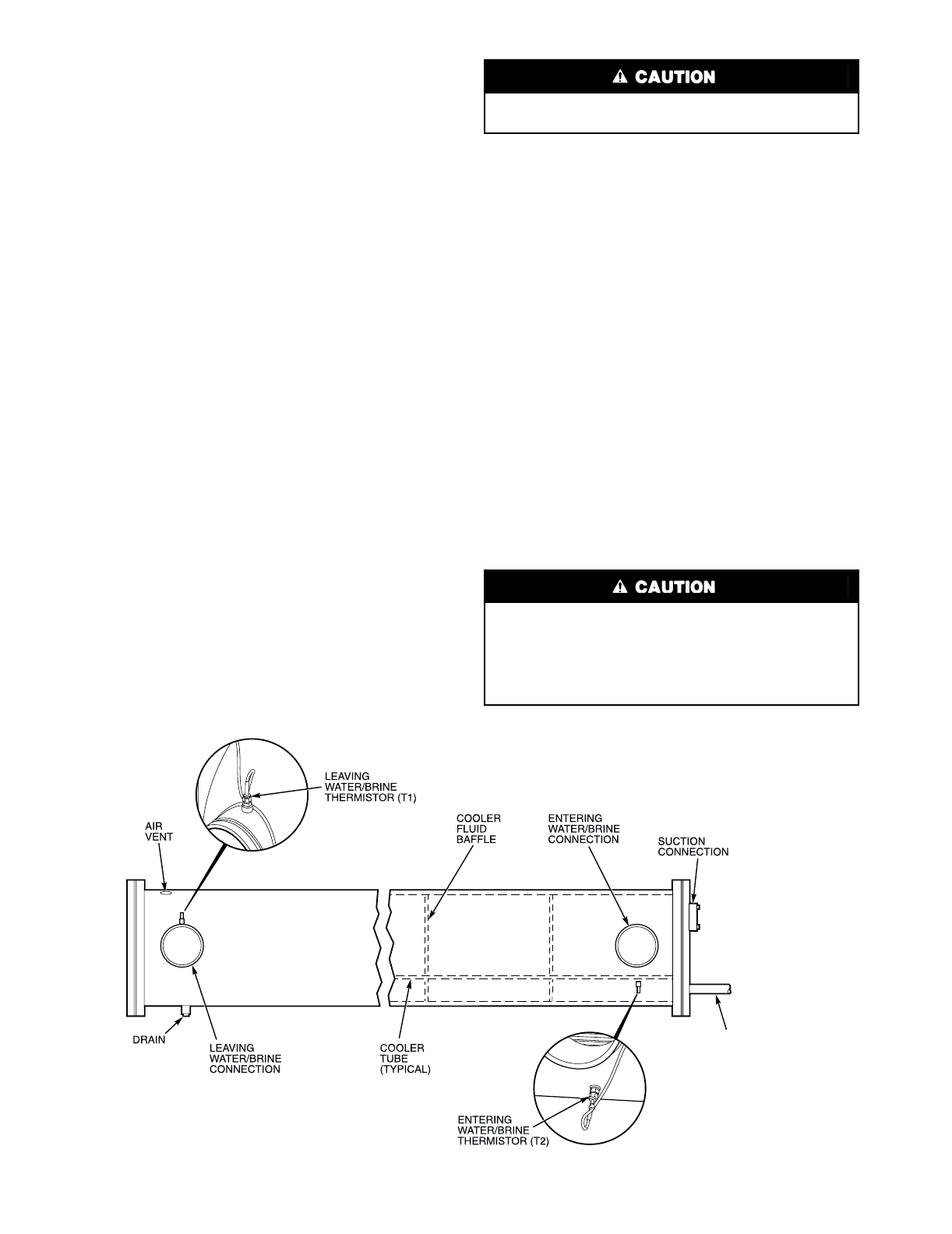
54
7. Remove the liquid lines by breaking the silver-soldered
joints at the cooler liquid line nozzles.
8. On 30GTN,GTR and 30GUN,R 080-110 and 230B-315B
units, remove the vertical support(s) under the condenser
coil in front of the cooler. Provide temporary support as
needed. Save all screws for reinstallation later.
9. Remove the screws in the cooler feet. Slide the cooler
slightly to the left to clear the refrigerant tubing. Save all
screws.
Removing the cooler can be accomplished in one of 2 ways,
depending on the jobsite. Either continue sliding the cooler to-
ward the end of the unit opposite the tubing and carefully re-
move, or pivot the cooler and remove it from the cooler side of
the unit.
REPLACING COOLER — To replace the cooler:
1. Insert new cooler carefully into place. Reattach the
screws into the cooler feet (using saved screws).
On 30GTN,GTR and 30GUN,GUR080-110 and 230B-
315B units, reattach the 2 vertical supports under the
condenser coil in front of the cooler using screws
saved.
2. Replace the liquid lines and solder at the cooler liquid line
nozzles.
3. Rebolt the suction flanges onto the cooler head using
bolts saved during removal. Use new gaskets for the suc-
tion line flanges. Use compressor oil to aid in gasket seal-
ing and tighten the suction flange bolts to 70 to 90 ft-lb
(94 to 122 N-m).
NOTE: The suction flange has a 4-bolt pattern. See
Carrier specified parts for replacement part number, if
necessary.
4. Using adhesive, reinstall the cooler insulation on the re-
frigerant connection end of the cooler.
5. Reinstall the thermistors. Refer to Thermistors section on
page 59, and install as follows:
a. Apply pipe sealant to the 1/4-in. NPT threads on
the replacement coupling for the fluid side, and
install it in place of the original.
b. Reinstall thermistor T1 well, and insert thermistor
T1 into well.
c. Install thermistor T2 (entering fluid temperature)
so that it is not touching an internal refrigerant
tube, but so that it is close enough to sense a freeze
condition. The recommended distance is 1/8 in.
(3.2 mm) from the cooler tube. Tighten the pack-
ing nut finger tight, and then tighten 11/4 turns
more using a back-up wrench.
6. Install the cooler heater and conduit (if equipped), con-
necting the wires as shown in the unit wiring schematic
located on the unit.
7. Close the air vent at the top of the cooler, and close the
drain on the bottom of the cooler near the leaving fluid
outlet. Both the drain and the air vent are located on the
leaving fluid end of the cooler. See Fig. 24.
8. Reconnect the cooler fluid piping and strainer, and open
the shutoff valves (if installed). Purge the fluid of all air
before starting unit.
9. Open the discharge service valves, close the circuit break-
ers, and open the liquid line service valves for the
compressors.
SERVICING THE COOLER — When cooler heads and par-
tition plates are removed, tube sheets are exposed showing
ends of tubes.
Do not use the packing nut to tighten the coupling. Damage
to the ferrules will result.
Certain tubes in the 10HB coolers cannot be removed.
Eight tubes in the bundle are secured inside the cooler to
the baffles and cannot be removed. These tubes are marked
by a dimple on the tube sheet. See Fig. 25. If any of these
tubes have developed a leak, plug the tube(s) as described
under Tube Plugging section on page 55.
LIQUID
CONNECTION
Fig. 24 — Cooler Thermistor Locations
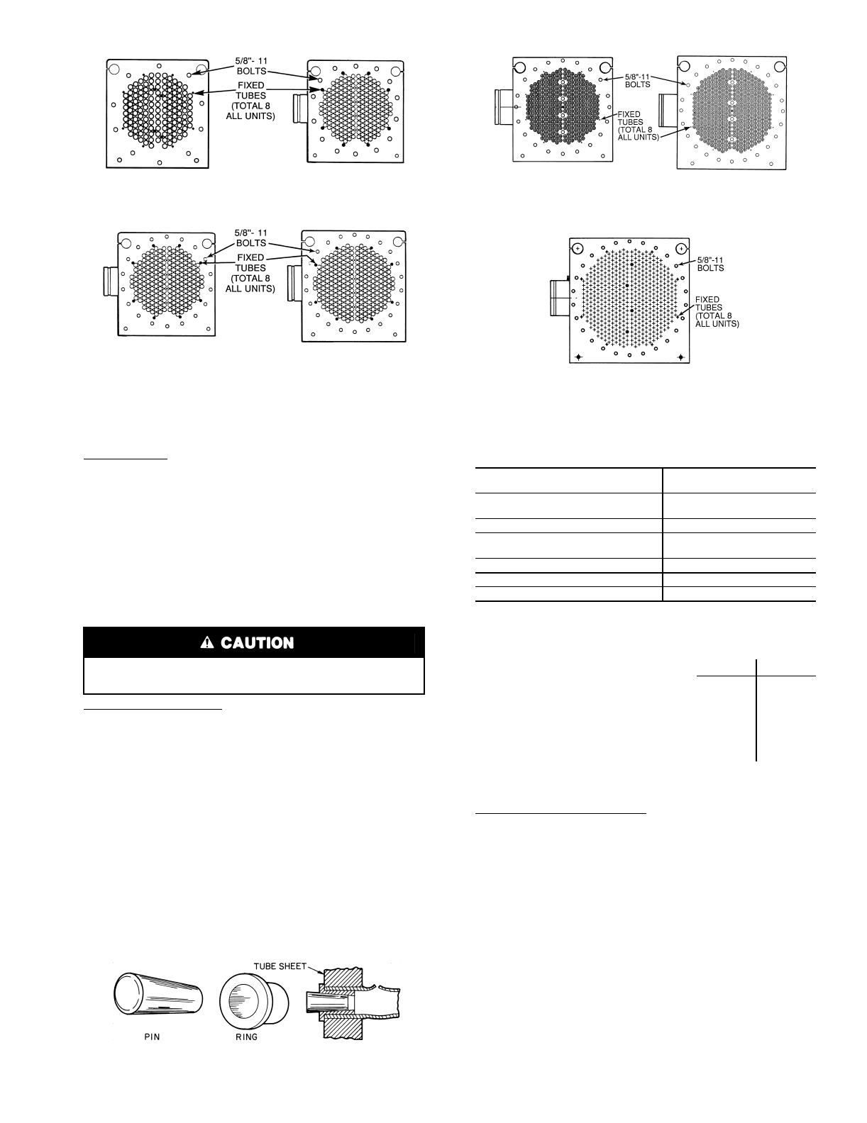
55
Tube Plugging — A leaky tube can be plugged until retubing
can be done. The number of tubes plugged determines how
soon cooler must be retubed. Tubes plugged in the following
locations will affect the performance of the unit: Any tube in
the area, particularly the tube that thermistor T2 is adjacent to,
will affect unit reliability and performance. Thermistor T2 is
used in the freeze protection algorithm for the controller. If sev-
eral tubes require plugging, check with your local Carrier rep-
resentative to find out how number and location can affect unit
capacity.
Figure 26 shows an Elliott tube plug and a cross-sectional
view of a plug in place.
Retubing (See Table 31) — When retubing is to be done, ob-
tain service of qualified personnel experienced in boiler main-
tenance and repair. Most standard procedures can be followed
when retubing the 10HB coolers. An 8% crush is recommend-
ed when rolling replacement tubes into the tubesheet. An 8%
crush can be achieved by setting the torque on the gun at 48 to
50 in.-lb (5.4 to 5.6 N-m).
The following Elliott Co. tube rolling tools are required:
B3400 Expander Assembly
B3401 Cage
B3405 Mandrel
B3408 Rolls
Place one drop of Loctite No. 675 or equivalent on top of
tube prior to rolling. This material is intended to “wick” into
the area of the tube that is not rolled into the tube sheet, and
prevent fluid from accumulating between the tube and the tube
sheet.
Table 31 — Plugs
*Order directly from: Elliott Tube Company, Dayton, Ohio.
†Can be obtained locally.
Tube information follows:
NOTE: Tubes next to gasket webs must be flush with tube
sheet (both ends).
Tightening Cooler Head Bolts
Gasket Preparation — When reassembling cooler heads,
always use new gaskets. Gaskets are neoprene-based and are
brushed with a light film of compressor oil. Do not soak gasket
or gasket deterioration will result. Use new gaskets within
30 minutes to prevent deterioration. Reassemble cooler nozzle
end or plain end cover of the cooler with the gaskets. Torque
all cooler bolts to the following specification and sequence:
5/8-in. Diameter Perimeter Bolts . . . . . . . . . . . . 150 to 170 ft-lb
(201 to 228 N-m)
1/2-in. Diameter Flange Bolts . . . . . . . . . . . . . . . . 70 to 90 ft-lb
(94 to 121 N-m)
1. Install all bolts finger tight.
2. Bolt tightening sequence is outlined in Fig. 27. Follow
the numbering or lettering sequence so that pressure is
evenly applied to gasket.
Use extreme care when installing plugs to prevent damage
to the tube sheet section between the holes.
COMPONENTS FOR
PLUGGING PART NUMBER
For Tubes
Brass Pin 853103-500*
Brass Ring 853002-570*
For Holes without Tubes
Brass Pin 853103-1*
Brass Ring 853002-631*
Loctite No. 675†
Locquic “N”†
in. mm
•Tube sheet hole diameter . . . . . . . . . . 0.631 16.03
•Tube OD . . . . . . . . . . . . . . . . . . . . . . 0.625 15.87
•Tube ID after rolling. . . . . . . . . . . . . . . 0.581 14.76
(includes expansion due to to
to clearance) 0.588 14.94
Fig. 26 — Elliott Tube Plug
SIZES 060,070
SIZES 080,090* SIZES 100,110*
SIZES 130,150* SIZES 170,190*
SIZE 210*
*And associated modular units (see Tables 1A and 1B).
Fig. 25 — Typical Tube Sheets, Cover Off (Non-Removable Tubes)
SIZES 040-050
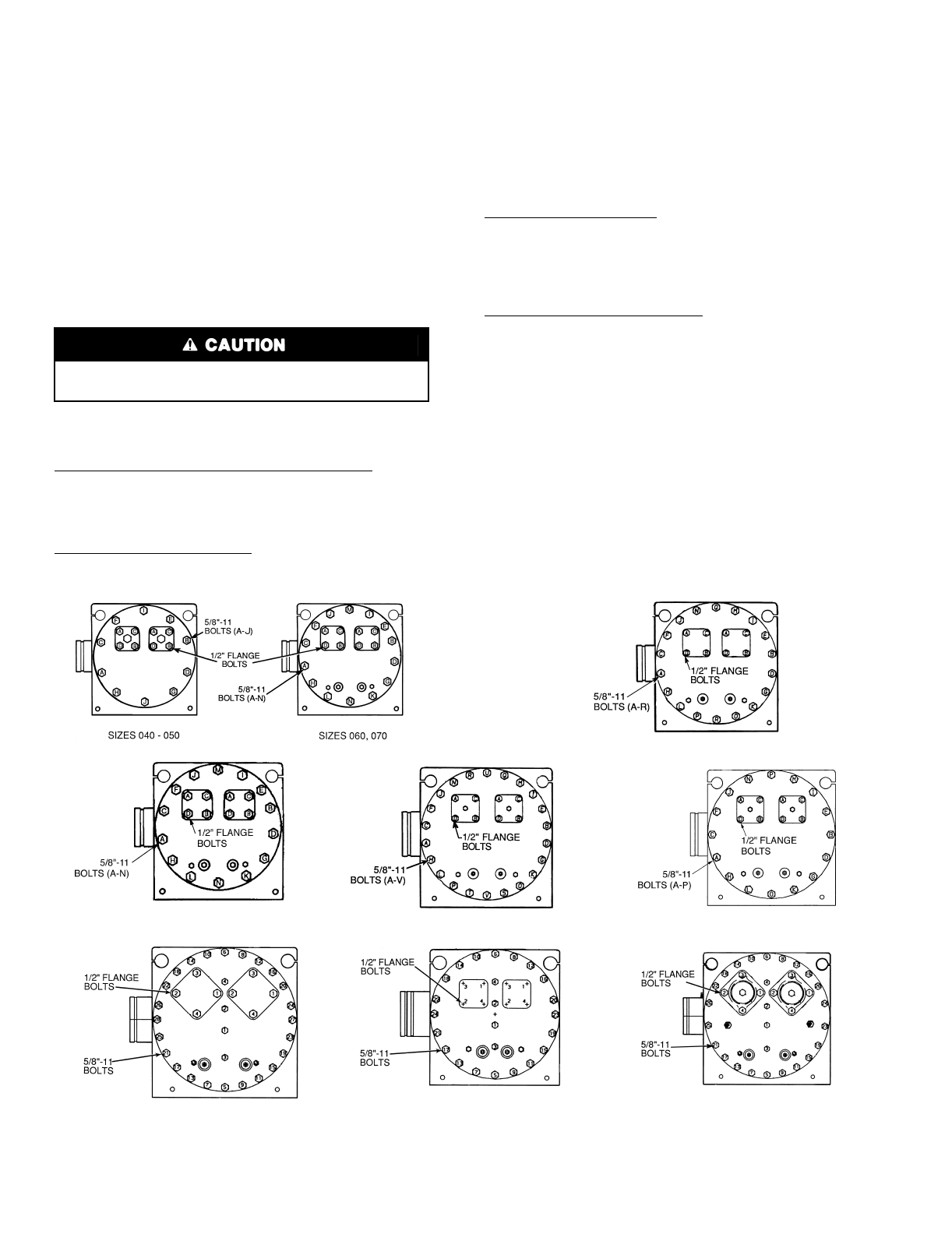
56
3. Apply torque in one-third steps until required torque is
reached. Load all bolts to each one-third step before pro-
ceeding to next one-third step.
4. No less than one hour later, retighten all bolts to required
torque values.
5. After refrigerant is restored to system, check for refriger-
ant leaks with soap solution or Halide device.
6. Replace cooler insulation.
Condenser Coils
COIL CLEANING — For standard aluminum, copper and
pre-coated aluminum fin coils, clean the coils with a vacuum
cleaner, fresh water, compressed air, or a bristle brush (not
wire). Units installed in corrosive environments should have
coil cleaning as part of a planned maintenance schedule. In this
type of application, all accumulations of dirt should be cleaned
off the coil.
CLEANING E-COATED COILS — Follow the outlined pro-
cedure below for proper care, cleaning and maintenance of
E-coated aluminum or copper fin coils:
Coil Maintenance and Cleaning Recommendations — Rou-
tine cleaning of coil surfaces is essential to maintain proper
operation of the unit. Elimination of contamination and
removal of harmful residues will greatly increase the life of the
coil and extend the life of the unit.
Remove Surface Loaded Fibers — Surface loaded fibers or
dirt should be removed with a vacuum cleaner. If a vacuum
cleaner is not available, a soft brush may be used. In either
case, the tool should be applied in the direction of the fins. Coil
surfaces can be easily damaged (fin edges bent over) if the tool
is applied across the fins.
NOTE: Use of a water stream, such as a garden hose, against a
surface loaded coil will drive the fibers and dirt into the coil.
This will make cleaning efforts more difficult. Surface loaded
fibers must be completely removed prior to using low velocity
clean water rinse.
Periodic Clean Water Rinse — A periodic clean water rinse is
very beneficial for coils that are applied in coastal or industrial
environments. However, it is very important that the water
rinse is made with very low velocity water stream to avoid
damaging the fin edges. Monthly cleaning as described below
is recommended.
Routine Cleaning of Coil Surfaces — Monthly cleaning
with Enviro-Shield™ Coil cleaner is essential to extend the life
of coils. It is recommended that all coils, including standard
aluminum, pre-coated, copper/copper or E-coated coils are
cleaned with the Enviro-Shield Coil Cleaner as described
below. Coil cleaning should be part of the units regularly
scheduled maintenance procedures to ensure long life of the
coil. Failure to clean the coils may result in reduced durability
in the environment.
Enviro-Shield Coil Cleaner is non-flammable, hypoaller-
genic, non-bacterial, USDA accepted biodegradable and 100%
ecologically safe agent that will not harm the coil or surround-
ing components such as electrical wiring, painted metal surfac-
es or insulation. Use of non-recommended coil cleaners is
strongly discouraged since coil and unit durability could be
affected.
Do not use high-pressure water or air to clean coils — fin
damage may result.
SIZES 080,090* WITH 18-BOLT HEADS
SIZES 080,090* WITH 14-BOLT HEADS SIZES 100,110* WITH 22-BOLT HEADS SIZES 100,110* WITH 16-BOLT HEADS
SIZES 130,150*
*And associated modular units.
Fig. 27 — Cooler Head Bolt Tightening Sequence (Typical Tube Sheet)
SIZES 170,190*
SIZE 210*
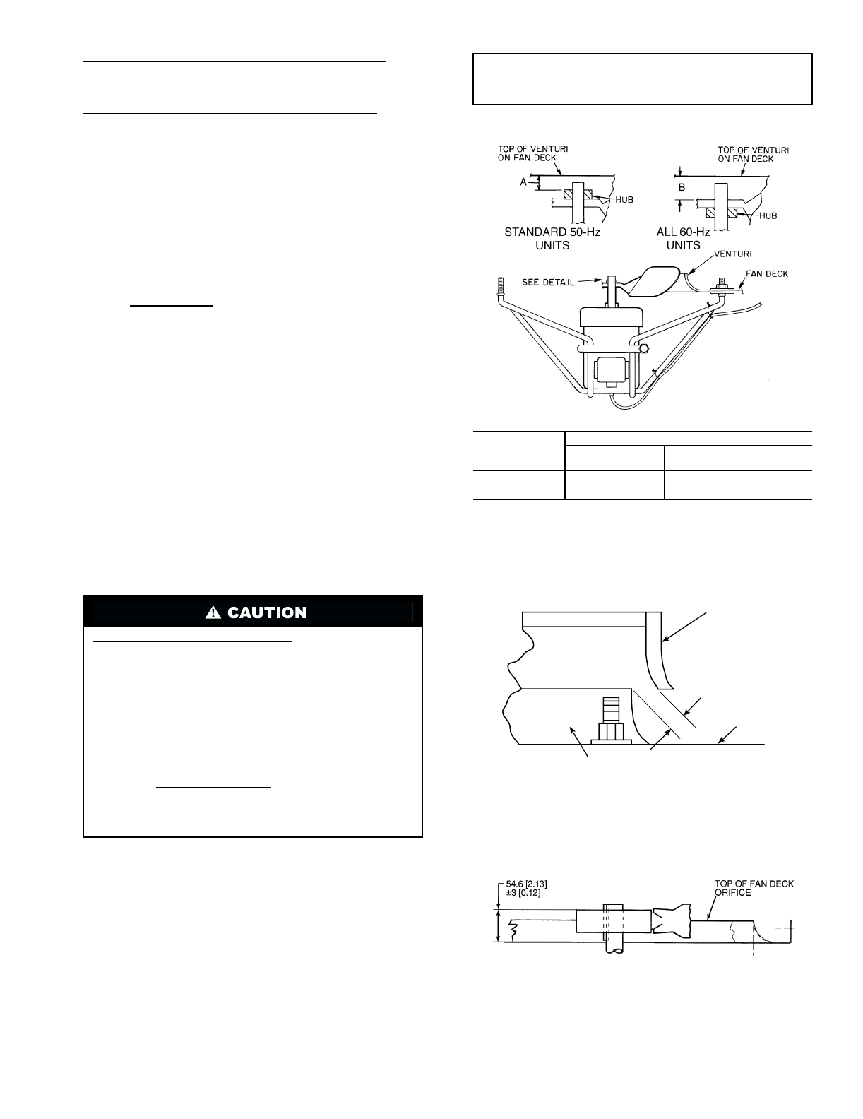
57
Enviro-Shield™ Coil Cleaner Application Equipment
•21/2 Gallon Garden Sprayer
•Water Rinse with Low Velocity Spray Nozzle
Enviro-Shield Coil Cleaner Application Instructions
•Although Enviro-Shield Coil cleaner is harmless to
humans, animals, and marine life, proper eye protection
such as safety glasses is recommended during mixing
and application.
•Remove all surface loaded fibers and dirt with a vacuum
cleaner as described above.
•Thoroughly wet finned surfaces with clean water and a
low velocity garden hose being careful not to bend fins.
•Mix Enviro-Shield Coil Cleaner in a 21/2 gallon garden
sprayer according to the instructions included with the
Enzyme Cleaner. The optimum solution temperature is
100 F.
NOTE: DO NOT USE water in excess of 130 F as the enzy-
matic activity will be destroyed.
•Thoroughly apply Enviro-Shield Coil cleaner solution to
all coil surfaces including finned area, tube sheets and
coil headers.
•Hold garden sprayer nozzle close to finned areas and
apply cleaner with a vertical, up-and-down motion.
Avoid spraying in horizontal pattern to minimize poten-
tial for fin damage.
•Ensure cleaner thoroughly penetrates deep into finned
areas.
•Interior and exterior finned areas must be thoroughly
cleaned.
•Finned surfaces should remain wet with cleaning solu-
tion for 10 minutes.
•Ensure surfaces are not allowed to dry before rinsing.
Reapply cleaner as needed to ensure 10-minute satura-
tion is achieved.
•Thoroughly rinse all surfaces with low velocity clean
water using downward rinsing motion of water spray
nozzle. Protect fins from damage from the spray nozzle.
Condenser Fans — Each fan is supported by a formed
wire mount bolted to fan deck and covered with a wire guard.
The exposed end of fan motor shaft is protected from weather
by grease. If fan motor must be removed for service or replace-
ment, be sure to regrease fan shaft and reinstall fan guard. For
proper performance, fan should be positioned as in Fig. 28A
and 28B (standard and low-noise applications). Tighten set-
screws to 15 ± 1 ft-lb (20 ± 1.3 N-m).
If the unit is equipped with the high-static fan option, the fan
must be set from the top of the fan deck to the plastic ring or
center of the fan to a distance of 2.13 in. ± 0.12 in.
(54 ± 3 mm). This is different from standard fans, since there is
no area available to measure from the top of the orifice ring to
the fan hub itself. See Fig. 29.
Harsh Chemical and Acid Cleaners — Harsh chemical,
household bleach or acid cleaners should not be used to
clean outdoor or indoors coils of any kind. These cleaners
can be very difficult to rinse out of the coil and can acceler-
ate corrosion at the fin/tube interface where dissimilar
materials are in contact. If there is dirt below the surface of
the coil, use the Enviro-Shield Coil Cleaner as described
above.
High Velocity Water or Compressed Air — High veloc-
ity water from a pressure washer, garden hose or com-
pressed air should never be used to clean a coil. The force
of the water or air jet will bend the fin edges and increase
airside pressure drop. Reduced unit performance or nui-
sance unit shutdown may occur.
IMPORTANT: Check for proper fan rotation (clockwise
viewed from above). If necessary, switch any 2 power
leads to reverse fan rotation.
PLASTIC FAN
PROPELLER
CLEARANCE
OF 0.25 INCHES
(6.4 MM)
FAN DECK
SURFACE
FAN ORIFICE
NOTE: Fan rotation is clockwise as viewed from top of unit.
Fig. 28A — Condenser Fan Adjustment —
Standard 50 and 60 Hz Units and
60 Hz Low Noise Fan Option Units
DIMENSION
FAN TYPE
Standard Low Noise 60 Hz Only
(Optional)
A0.50” (13 mm) 1.50” (38 mm)
B0.88” (22 mm) 1.13” (29 mm)
Fig. 28B — Condenser Fan Adjustment —
50 Hz Low Noise Fan Option Units
NOTE: Dimensions are in millimeters. Dimensions in [ ] are in
inches.
Fig. 29 — Condenser Fan Adjustment,
Units with High-Static Fan Operation
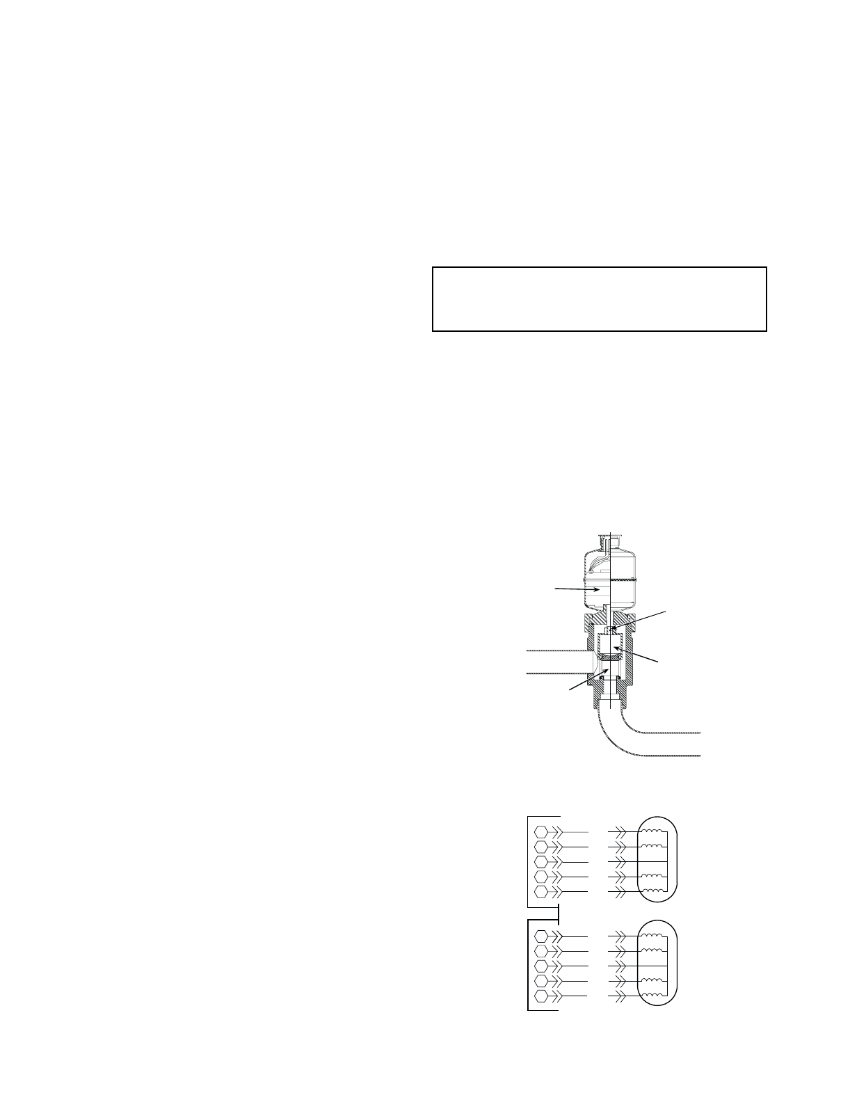
58
Refrigerant Feed Components — Each circuit has
all necessary refrigerant controls.
ELECTRONIC EXPANSION VALVE (EXV) — A cut-
away view of valve is shown in Fig. 30.
High-pressure liquid refrigerant enters valve through bot-
tom. A series of calibrated slots have been machined in side of
orifice assembly. As refrigerant passes through orifice, pressure
drops and refrigerant changes to a 2-phase condition (liquid
and vapor). To control refrigerant flow for different operating
conditions, a sleeve moves up and down over orifice and mod-
ulates orifice size. A sleeve is moved by a linear stepper motor.
Stepper motor moves in increments and is controlled directly
by EXV module. As stepper motor rotates, motion is trans-
ferred into linear movement by lead screw. Through stepper
motor and lead screw, 1500 discrete steps of motion are ob-
tained. The large number of steps and long stroke results in
very accurate control of refrigerant flow. The minimum posi-
tion for operation is 120 steps.
The EXV module controls the valve. The lead compressor
in each circuit has a thermistor located in the suction manifold
after the compressor motor and a thermistor located in a well
where the refrigerant enters the cooler. The thermistors mea-
sure the temperature of the superheated gas entering the com-
pressor cylinders and the temperature of the refrigerant enter-
ing the cooler. The difference between the temperature of the
superheated gas and the cooler suction temperature is the su-
perheat. The EXV module controls the position of the electron-
ic expansion valve stepper motor to maintain superheat set
point.
The superheat leaving cooler is approximately 3° to 5° F
(2° to 3° C), or less.
Because EXV status is communicated to the Main Base
Board (MBB) and is controlled by the EXV modules (see
Fig. 31), it is possible to track the valve position. By this
means, head pressure is controlled and unit is protected against
loss of charge and a faulty valve. During initial start-up, EXV
is fully closed. After initialization period, valve position is
tracked by the EXV module by constantly monitoring amount
of valve movement.
The EXV is also used to limit cooler saturated suction tem-
perature to 50 F (10 C). This makes it possible for the chiller to
start at higher cooler fluid temperatures without overloading
the compressor. This is commonly referred to as MOP (maxi-
mum operating pressure).
If it appears that EXV is not properly controlling circuit op-
eration to maintain correct superheat, there are a number of
checks that can be made using test functions and initialization
features built into the microprocessor control. See Service Test
section on page 29 to test EXVs.
NOTE: The EXV orifice is a screw-in type and may be
removed for inspection and cleaning. Once the motor canister
is removed the orifice can be removed by using the orifice
removal tool (part no. TS429). A slot has been cut in the top of
the orifice to facilitate removal. Turn orifice counterclockwise
to remove. A large screwdriver may also be used.
When cleaning or reinstalling orifice assembly be careful
not to damage orifice assembly seals. The bottom seal acts as a
liquid shut-off, replacing a liquid line solenoid valve. If the bot-
tom seal should become damaged it can be replaced. Remove
the orifice. Remove the old seal. Using the orifice as a guide,
add a small amount of O-ring grease, to the underside of the or-
ifice. Be careful not to plug the vent holes. Carefully set the
seal with the O-ring into the orifice. The O-ring grease will
hold the seal in place. If the O-ring grease is not used, the seal
O-ring will twist and bind when the orifice is screwed into the
EXV base. Install the orifice and seal assembly. Remove the
orifice to verify that the seal is properly positioned. Clean any
O-ring grease from the bottom of the orifice. Reinstall the ori-
fice and tighten to 100 in.-lb (11 N-m). Apply a small amount
of O-ring grease to the housing seal O-ring before installing the
motor canister. Reinstall the motor canister assembly. Tighten
the motor nut to 15 to 25 ft-lb (20 to 34 N-m).
Check EXV operation using test functions described in the
Service Test section on page 29.
MOISTURE-LIQUID INDICATOR — Clear flow of liquid
refrigerant indicates sufficient charge in system. Bubbles in the
sight glass indicate undercharged system or presence of non-
condensables. Moisture in system measured in parts per mil-
lion (ppm), changes color of indicator:
Green — moisture is below 45 ppm;
Yellow-green (chartreuse) — 45 to 130 ppm (caution);
Yellow (wet) — above 130 ppm.
Change filter drier at first sign of moisture in system.
FILTER DRIER — Whenever moisture-liquid indicator
shows presence of moisture, replace filter drier(s). There is one
filter drier on each circuit. Refer to Carrier Standard Service
Techniques Manual, Chapter 1, Refrigerants, for details on ser-
vicing filter driers.
LIQUID LINE SOLENOID VALVE — All TXV units have
a liquid line solenoid valve to prevent liquid refrigerant migra-
tion to low side of system during the off cycle.
LIQUID LINE SERVICE VALVE — This valve is located
immediately ahead of filter drier, and has a 1/4-in. Schrader
connection for field charging. In combination with compressor
discharge service valve, each circuit can be pumped down into
the high side for servicing.
IMPORTANT: Unit must be in operation at least
12 hours before moisture indicator can give an accurate
reading. With unit running, indicating element must be
in contact with liquid refrigerant to give true reading.
STEPPER
MOTOR (12 VDC)
ORIFICE ASSEMBLY
(INSIDE PISTON SLEEVE)
PISTON SLEEVE
LEAD SCREW
Fig. 30 — Electronic Expansion Valve (EXV)
3
3
1
2
4
5
1
2
3
4
5
1
2
3
4
5
1
2
4
5
BRN
WHT
RED
BLK
GRN
A
E
D
B
C
PL-EXVB
EXV-B
BRN
WHT
RED
BLK
GRN
J7
J6
PL-EXVA
C
B
D
A
E
EXV-A
ELECTRONIC EXPANSION VALVES (EXVs)
Fig. 31 — Printed Circuit Board Connector
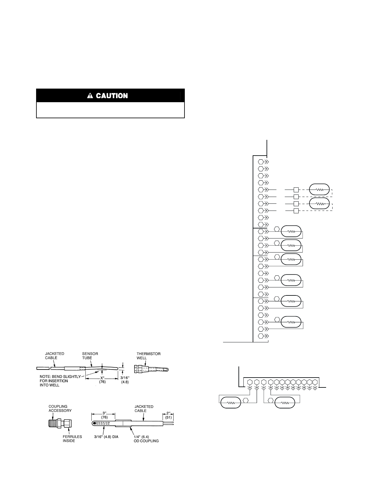
59
Thermistors — Electronic control uses 4 to 10 ther-
mistors to sense temperatures used to control the operation of
chiller.
Thermistors T1-T9 vary in their temperature vs resistance
and voltage drop performance. Thermistor T10 is a 10 kΩ in-
put channel and has a different set of temperature vs resistance
and voltage drop performance. Resistances at various tempera-
tures are listed in Tables 32A-33B.
LOCATION — General locations of thermistor sensors are
shown in Fig. 7-10. See Table 2 for pin connection points.
REPLACING THERMISTOR T2
1. Remove and discard original sensor and coupling. Do
not disassemble new coupling. Install assembly as
received. See Fig. 32.
2. Apply pipe sealant to 1/4-in. NPT threads on replacement
coupling, and install in place of original. Do not use the
packing nut to tighten coupling. Damage to ferrules will
result.
3. Thermistor T2 (entering fluid temperature) should not be
touching an internal refrigerant tube, but should be close
enough to sense a freeze condition. Recommended dis-
tance is 1/8 in. (3.2 mm) from cooler tube. Tighten pack-
ing nut finger tight to position ferrules, then tighten 11/4
turns more using a back-up wrench. Ferrules are now at-
tached to the sensor, which can be withdrawn from cou-
pling for service.
REPLACING THERMISTORS T1, T5, T6, T7, AND
T8 — Add a small amount of thermal conductive grease to
thermistor well. Thermistors are friction-fit thermistors, which
must be slipped into wells located in the cooler leaving fluid
nozzle for T1, in the cooler head for T5 and T6 (EXV units
only), and in the compressor pump end for T7 and T8 (EXV
units only).
THERMISTORS T3 AND T4 — These thermistors are
located on header end of condenser coil. They are clamped on
a return bend.
THERMISTOR/TEMPERATURE SENSOR CHECK — A
high quality digital volt-ohmmeter is required to perform this
check.
1. Connect the digital voltmeter across the appropriate
thermistor terminals at the J8 terminal strip on the
Main Base Board for thermistors T1-T6, T9, T10; or
the J5 terminal strip on the EXV Board for thermistors
T7 and T8 (see Fig. 33). Using the voltage reading
obtained, read the sensor temperature from
Tables 32A-33B. To check thermistor accuracy, mea-
sure temperature at probe location with an accurate
thermocouple-type temperature measuring instru-
ment. Insulate thermocouple to avoid ambient temper-
atures from influencing reading. Temperature
measured by thermocouple and temperature deter-
mined from thermistor voltage reading should be
close, ± 5° F (3° C) if care was taken in applying ther-
mocouple and taking readings.
2. If a more accurate check is required, unit must be shut
down and thermistor removed and checked at a known
temperature (freezing point or boiling point of water) us-
ing either voltage drop measured across thermistor at the
J8 or J5 terminals, by determining the resistance with
chiller shut down and thermistor disconnected from J8 or
J5. Compare the values determined with the value read by
the control in the Temperatures mode using the Marquee
display.
Sensor T2 is installed directly in the fluid circuit. Relieve
all pressure or drain fluid before removing.
FLUID-SIDE TEMPERATURE SENSOR (T1) AND
REFRIGERANT TEMPERATURE SENSOR (T5, T6, T7, T8)
FLUID-SIDE TEMPERATURE SENSOR (T2)
NOTE: Dimensions in ( ) are in millimeters.
Fig. 32 — Thermistors (Temperature Sensors)
X = T1,T5,T6 = 3″ (76)
T7,T8 = 4″ (102)
1
2
3
4
1
2
3
4
26
25
24
23
22
21
20
19
18
17
16
15
14
13
12
11
10
9
8
7
6
5BLU
BLU
PNK
PNK
TB5
TB5
TB5
TB5
5
6
7
8
T10
T9
REMOTE SPACE TEMP
(ACCESSORY)
5
6
7
8
9
10
1
2
3
4
1
2
3
4
5
6
1
2
3
4
5
6
2
1
4
6
3
5T5
T3
T4
T6
T2
T1
COOLER ENTERING
FLUID TEMP
OUTDOOR-AIR TEMP
(ACCESSORY) OR
DUAL CHILLER LWT
COOLER LEAVING
FLUID TEMP
SATURATED
CONDENSING TEMP-
CIRCUIT B
SATURATED
SUCTION TEMP-
CIRCUIT B*
SATURATED
CONDENSING TEMP-
CIRCUIT A
SATURATED
SUCTION TEMP-
CIRCUIT A*
MAIN BASE BOARD
J8
T1-T6, T9, T10 THERMISTORS
J5
EXV BOARD
12 11 10 9 87654321
12 11 10 9
T8
8
T7 7
CKTA* CKTB*
COMPRESSOR RETURN GAS TEMP
T7, T8 THERMISTORS
LEGEND
*Not used on units with TXV (Thermostatic Expansion Valve) FIOP
(Factory-Installed Option).
Fig. 33 — Thermistor Connections to J5 and J8
Processor Boards
LWT —Leaving Fluid Temperature
60
Table 32A — 5K Thermistor Temperature (F) vs Resistance/Voltage
VOLTAGE DROP A FOR THERMISTORS T1, T2, T7-T9
VOLTAGE DROP B FOR THERMISTORS T3-T6
TEMP
(F)
VOLTAGE
DROP A
(V)
VOLTAGE
DROP B
(V)
RESISTANCE
(Ohms)
–25 3.699 4.538 98,010
–24 3.689 4.523 94,707
–23 3.679 4.508 91,522
–22 3.668 4.493 88,449
–21 3.658 4.476 85,486
–20 3.647 4.460 82,627
–19 3.636 4.444 79,871
–18 3.624 4.427 77,212
–17 3.613 4.409 74,648
–16 3.601 4.391 72,175
–15 3.588 4.373 69,790
–14 3.576 4.354 67,490
–13 3.563 4.335 65,272
–12 3.550 4.316 63,133
–11 3.536 4.296 61,070
–10 3.523 4.276 59,081
–93.509 4.255 57,162
–83.494 4.234 55,311
–73.480 4.213 53,526
–63.465 4.191 51,804
–53.450 4.169 50,143
–43.434 4.146 48,541
–33.418 4.123 46,996
–23.402 4.100 45,505
–13.386 4.076 44,066
03.369 4.052 42,679
13.352 4.027 41,339
23.335 4.002 40,047
33.317 3.976 38,800
43.299 3.951 37,596
53.281 3.924 36,435
63.262 3.898 35,313
73.243 3.871 34,231
83.224 3.844 33,185
93.205 3.816 32,176
10 3.185 3.788 31,202
11 3.165 3.760 30,260
12 3.145 3.731 29,351
13 3.124 3.702 28,473
14 3.103 3.673 27,624
15 3.082 3.643 26,804
16 3.060 3.613 26,011
17 3.038 3.583 25,245
18 3.016 3.552 24,505
19 2.994 3.522 23,789
20 2.972 3.490 23,096
21 2.949 3.459 22,427
22 2.926 3.428 21,779
23 2.903 3.396 21,153
24 2.879 3.364 20,547
25 2.856 3.331 19,960
26 2.832 3.299 19,393
27 2.808 3.266 18,843
28 2.784 3.234 18,311
29 2.759 3.201 17,796
30 2.735 3.168 17,297
31 2.710 3.134 16,814
32 2.685 3.101 16,346
33 2.660 3.068 15,892
34 2.634 3.034 15,453
35 2.609 3.000 15,027
36 2.583 2.966 14,614
37 2.558 2.933 14,214
38 2.532 2.899 13,826
39 2.506 2.865 13,449
40 2.480 2.831 13,084
41 2.454 2.797 12,730
42 2.428 2.764 12,387
43 2.402 2.730 12,053
44 2.376 2.696 11,730
45 2.349 2.662 11,416
46 2.323 2.628 11,112
47 2.296 2.594 10,816
48 2.270 2.561 10,529
49 2.244 2.527 10,250
50 2.217 2.494 9,979
51 2.191 2.461 9,717
52 2.165 2.427 9,461
53 2.138 2.395 9,213
54 2.112 2.362 8,973
55 2.086 2.329 8,739
56 2.060 2.296 8,511
57 2.034 2.264 8,291
58 2.008 2.232 8,076
TEMP
(F)
VOLTAGE
DROP A
(V)
VOLTAGE
DROP B
(V)
RESISTANCE
(Ohms)
59 1.982 2.200 7,686
60 1.956 2.168 7,665
61 1.930 2.137 7,468
62 1.905 2.105 7,277
63 1.879 2.074 7,091
64 1.854 2.043 6,911
65 1.829 2.013 6,735
66 1.804 1.982 6,564
67 1.779 1.952 6,399
68 1.754 1.923 6,238
69 1.729 1.893 6,081
70 1.705 1.864 5,929
71 1.681 1.835 5,781
72 1.656 1.806 5,637
73 1.632 1.778 5,497
74 1.609 1.749 5,361
75 1.585 1.722 5,229
76 1.562 1.694 5,101
77 1.538 1.667 4,976
78 1.516 1.640 4,855
79 1.493 1.613 4,737
80 1.470 1.587 4,622
81 1.448 1.561 4,511
82 1.426 1.535 4,403
83 1.404 1.510 4,298
84 1.382 1.485 4,196
85 1.361 1.460 4,096
86 1.340 1.436 4,000
87 1.319 1.412 3,906
88 1.298 1.388 3,814
89 1.278 1.365 3,726
90 1.257 1.342 3,640
91 1.237 1.319 3,556
92 1.217 1.296 3,474
93 1.198 1.274 3,395
94 1.179 1.253 3,318
95 1.160 1.231 3,243
96 1.141 1.210 3,170
97 1.122 1.189 3,099
98 1.104 1.169 3,031
99 1.086 1.148 2,964
100 1.068 1.128 2,898
101 1.051 1.109 2,835
102 1.033 1.089 2,773
103 1.016 1.070 2,713
104 0.999 1.051 2,655
105 0.983 1.033 2,597
106 0.966 1.015 2,542
107 0.950 0.997 2,488
108 0.934 0.980 2,436
109 0.918 0.963 2,385
110 0.903 0.946 2,335
111 0.888 0.929 2,286
112 0.873 0.913 2,239
113 0.858 0.896 2,192
114 0.843 0.881 2,147
115 0.829 0.865 2,103
116 0.815 0.850 2,060
117 0.801 0.835 2,018
118 0.787 0.820 1,977
119 0.774 0.805 1,937
120 0.761 0.791 1,898
121 0.748 0.777 1,860
122 0.735 0.763 1,822
123 0.723 0.750 1,786
124 0.710 0.736 1,750
125 0.698 0.723 1,715
126 0.686 0.710 1,680
127 0.674 0.698 1,647
128 0.663 0.685 1,614
129 0.651 0.673 1,582
130 0.640 0.661 1,550
131 0.629 0.650 1,519
132 0.618 0.638 1,489
133 0.608 0.627 1,459
134 0.597 0.616 1,430
135 0.587 0.605 1,401
136 0.577 0.594 1,373
137 0.567 0.584 1,345
138 0.557 0.573 1,318
139 0.548 0.563 1,291
140 0.538 0.553 1,265
141 0.529 0.543 1,240
142 0.520 0.534 1,214
TEMP
(F)
VOLTAGE
DROP A
(V)
VOLTAGE
DROP B
(V)
RESISTANCE
(Ohms)
143 0.511 0.525 1,190
144 0.502 0.515 1,165
145 0.494 0.506 1,141
146 0.485 0.497 1,118
147 0.477 0.489 1,095
148 0.469 0.480 1,072
149 0.461 0.471 1,050
150 0.453 0.463 1,029
151 0.445 0.455 1,007
152 0.438 0.447 986
153 0.430 0.449 965
154 0.423 0.432 945
155 0.416 0.424 925
156 0.408 0.417 906
157 0.402 0.410 887
158 0.395 0.403 868
159 0.388 0.396 850
160 0.381 0.389 832
161 0.375 0.382 815
162 0.369 0.376 798
163 0.362 0.369 782
164 0.356 0.363 765
165 0.350 0.357 750
166 0.344 0.351 734
167 0.339 0.345 719
168 0.333 0.339 705
169 0.327 0.333 690
170 0.322 0.327 677
171 0.317 0.322 663
172 0.311 0.316 650
173 0.306 0.311 638
174 0.301 0.306 626
175 0.296 0.301 614
176 0.291 0.295 602
177 0.286 0.291 591
178 0.282 0.286 581
179 0.277 0.281 570
180 0.272 0.276 561
181 0.268 0.272 551
182 0.264 0.267 542
183 0.259 0.263 533
184 0.255 0.258 524
185 0.251 0.254 516
186 0.247 0.250 508
187 0.243 0.246 501
188 0.239 0.242 494
189 0.235 0.238 487
190 0.231 0.234 480
191 0.228 0.230 473
192 0.224 0.226 467
193 0.220 0.223 461
194 0.217 0.219 456
195 0.213 0.216 450
196 0.210 0.212 445
197 0.206 0.209 439
198 0.203 0.205 434
199 0.200 0.202 429
200 0.197 0.199 424
201 0.194 0.196 419
202 0.191 0.192 415
203 0.188 0.189 410
204 0.185 0.186 405
205 0.182 0.183 401
206 0.179 0.181 396
207 0.176 0.178 391
208 0.173 0.175 386
209 0.171 0.172 382
210 0.168 0.169 377
211 0.165 0.167 372
212 0.163 0.164 367
213 0.160 0.162 361
214 0.158 0.159 356
215 0.155 0.157 350
216 0.153 0.154 344
217 0.151 0.152 338
218 0.148 0.150 332
219 0.146 0.147 325
220 0.144 0.145 318
221 0.142 0.143 311
222 0.140 0.141 304
223 0.138 0.138 297
224 0.135 0.136 289
225 0.133 0.134 282
61
Table 32B — 5K Thermistor Temperature (C) vs Resistance/Voltage (cont)
VOLTAGE DROP A FOR THERMISTORS T1, T2, T7-T9
VOLTAGE DROP B FOR THERMISTORS T3-T6
TEMP
(C)
VOLTAGE
DROP A
(V)
VOLTAGE
DROP B
(V)
RESISTANCE
(Ohms)
–32 3.705 4.547 100,260
–31 3.687 4.520 94,165
–30 3.668 4.493 88,480
–29 3.649 4.464 83,170
–28 3.629 4.433 78,125
–27 3.608 4.402 73,580
–26 3.586 4.369 69,250
–25 3.563 4.335 65,205
–24 3.539 4.300 61,420
–23 3.514 4.264 57,875
–22 3.489 4.226 54,555
–21 3.462 4.187 51,450
–20 3.434 4.146 48,536
–19 3.406 4.104 45,807
–18 3.376 4.061 43,247
–17 3.345 4.017 40,845
–16 3.313 3.971 38,592
–15 3.281 3.924 38,476
–14 3.247 3.876 34,489
–13 3.212 3.827 32,621
–12 3.177 3.777 30,866
–11 3.140 3.725 29,216
–10 3.103 3.673 27,633
–93.065 3.619 26,202
–83.025 3.564 24,827
–72.985 3.509 23,532
–62.945 3.453 22,313
–52.903 3.396 21,163
–42.860 3.338 20,079
–32.817 3.279 19,058
–22.774 3.221 18,094
–12.730 3.161 17,184
02.685 3.101 16,325
12.639 3.041 15,515
22.593 2.980 14,749
32.547 2.919 14,026
42.500 2.858 13,342
52.454 2.797 12,696
62.407 2.737 12,085
72.360 2.675 11,506
82.312 2.615 10,959
92.265 2.554 10,441
10 2.217 2.494 9,949
11 2.170 2.434 9,485
12 2.123 2.375 9,044
13 2.076 2.316 8,627
14 2.029 2.258 8,231
TEMP
(C)
VOLTAGE
DROP A
(V)
VOLTAGE
DROP B
(V)
RESISTANCE
(Ohms)
15 1.982 2.200 7,855
16 1.935 2.143 7,499
17 1.889 2.087 7,161
18 1.844 2.031 6,840
19 1.799 1.976 6,536
20 1.754 1.923 6,246
21 1.710 1.870 5,971
22 1.666 1.817 5,710
23 1.623 1.766 5,461
24 1.580 1.716 5,225
25 1.538 1.667 5,000
26 1.497 1.619 4,786
27 1.457 1.571 4,583
28 1.417 1.525 4,389
29 1.378 1.480 4,204
30 1.340 1.436 4,028
31 1.302 1.393 3,861
32 1.265 1.351 3,701
33 1.229 1.310 3,549
34 1.194 1.270 3,404
35 1.160 1.231 3,266
36 1.126 1.193 3,134
37 1.093 1.156 3,008
38 1.061 1.120 2,888
39 1.030 1.085 2,773
40 0.999 1.051 2,663
41 0.969 1.019 2,559
42 0.940 0.987 2,459
43 0.912 0.956 2,363
44 0.885 0.926 2,272
45 0.858 0.896 2,184
46 0.832 0.868 2,101
47 0.807 0.841 2,021
48 0.782 0.814 1,944
49 0.758 0.788 1,871
50 0.735 0.763 1,801
51 0.713 0.739 1,734
52 0.691 0.716 1,670
53 0.669 0.693 1,609
54 0.649 0.671 1,550
55 0.629 0.650 1,493
56 0.610 0.629 1,439
57 0.591 0.609 1,387
58 0.573 0.590 1,337
59 0.555 0.571 1,290
60 0.538 0.553 1,244
61 0.522 0.536 1,200
TEMP
(C)
VOLTAGE
DROP A
(V)
VOLTAGE
DROP B
(V)
RESISTANCE
(Ohms)
62 0.506 0.519 1,158
63 0.490 0.502 1,118
64 0.475 0.487 1,079
65 0.461 0.471 1,041
66 0.447 0.457 1,006
67 0.433 0.443 971
68 0.420 0.429 938
69 0.407 0.415 906
70 0.395 0.403 876
71 0.383 0.390 836
72 0.371 0.378 805
73 0.360 0.367 775
74 0.349 0.355 747
75 0.339 0.345 719
76 0.329 0.334 693
77 0.319 0.324 669
78 0.309 0.314 645
79 0.300 0.305 623
80 0.291 0.295 602
81 0.283 0.287 583
82 0.274 0.278 564
83 0.266 0.270 547
84 0.258 0.262 531
85 0.251 0.254 516
86 0.244 0.247 502
87 0.237 0.239 489
88 0.230 0.232 477
89 0.223 0.226 466
90 0.217 0.219 456
91 0.211 0.213 446
92 0.204 0.207 436
93 0.199 0.201 427
94 0.193 0.195 419
95 0.188 0.189 410
96 0.182 0.184 402
97 0.177 0.179 393
98 0.172 0.174 385
99 0.168 0.169 376
100 0.163 0.164 367
101 0.158 0.160 357
102 0.154 0.155 346
103 0.150 0.151 335
104 0.146 0.147 324
105 0.142 0.143 312
106 0.138 0.139 299
107 0.134 0.135 285
62
Table 33A — 10K Thermistor Temperatures (°F) vs Resistance/Voltage Drop
(For Thermistor T10)
TEMP
(F)
VOLTAGE
DROP (V)
RESISTANCE
(Ohms)
–25 4.758 196,453
–24 4.750 189,692
–23 4.741 183,300
–22 4.733 177,000
–21 4.724 171,079
–20 4.715 165,238
–19 4.705 159,717
–18 4.696 154,344
–17 4.686 149,194
–16 4.676 144,250
–15 4.665 139,443
–14 4.655 134,891
–13 4.644 130,402
–12 4.633 126,183
–11 4.621 122,018
–10 4.609 118,076
–94.597 114,236
–84.585 110,549
–74.572 107,006
–64.560 103,558
–54.546 100,287
–44.533 97,060
–34.519 94,020
–24.505 91,019
–14.490 88,171
04.476 85,396
14.461 82,729
24.445 80,162
34.429 77,662
44.413 75,286
54.397 72,940
64.380 70,727
74.363 68,542
84.346 66,465
94.328 64,439
10 4.310 62,491
11 4.292 60,612
12 4.273 58,781
13 4.254 57,039
14 4.235 55,319
15 4.215 53,693
16 4.195 52,086
17 4.174 50,557
18 4.153 49,065
19 4.132 47,627
20 4.111 46,240
21 4.089 44,888
22 4.067 43,598
23 4.044 42,324
24 4.021 41,118
25 3.998 39,926
26 3.975 38,790
27 3.951 37,681
28 3.927 36,610
29 3.903 35,577
30 3.878 34,569
31 3.853 33,606
32 3.828 32,654
33 3.802 31,752
34 3.776 30,860
35 3.750 30,009
36 3.723 29,177
37 3.697 28,373
38 3.670 27,597
39 3.654 26,838
40 3.615 26,113
41 3.587 25,396
42 3.559 24,715
43 3.531 24,042
44 3.503 23,399
45 3.474 22,770
46 3.445 22,161
47 3.416 21,573
48 3.387 20,998
49 3.357 20,447
50 3.328 19,903
51 3.298 19,386
52 3.268 18,874
53 3.238 18,384
54 3.208 17,904
55 3.178 17,441
56 3.147 16,991
57 3.117 16,552
58 3.086 16,131
59 3.056 15,714
60 3.025 15,317
TEMP
(F)
VOLTAGE
DROP (V)
RESISTANCE
(Ohms)
61 2.994 14,925
62 2.963 14,549
63 2.932 14,180
64 2.901 13,824
65 2.870 13,478
66 2.839 13,139
67 2.808 12,814
68 2.777 12,493
69 2.746 12,187
70 2.715 11,884
71 2.684 11,593
72 2.653 11,308
73 2.622 11,031
74 2.592 10,764
75 2.561 10,501
76 2.530 10,249
77 2.500 10,000
78 2.470 9,762
79 2.439 9,526
80 2.409 9,300
81 2.379 9,078
82 2.349 8,862
83 2.319 8,653
84 2.290 8,448
85 2.260 8,251
86 2.231 8,056
87 2.202 7,869
88 2.173 7,685
89 2.144 7,507
90 2.115 7,333
91 2.087 7,165
92 2.059 6,999
93 2.030 6,838
94 2.003 6,683
95 1.975 6,530
96 1.948 6,383
97 1.921 6,238
98 1.894 6,098
99 1.867 5,961
100 1.841 5,827
101 1.815 5,698
102 1.789 5,571
103 1.763 5,449
104 1.738 5,327
105 1.713 5,210
106 1.688 5,095
107 1.663 4,984
108 1.639 4,876
109 1.615 4,769
110 1.591 4,666
111 1.567 4,564
112 1.544 4,467
113 1.521 4,370
114 1.498 4,277
115 1.475 4.185
116 1.453 4,096
117 1.431 4,008
118 1.409 3,923
119 1.387 3,840
120 1.366 3,759
121 1.345 3,681
122 1.324 3,603
123 1.304 3,529
124 1.284 3,455
125 1.264 3,383
126 1.244 3,313
127 1.225 3,244
128 1.206 3,178
129 1.187 3,112
130 1.168 3,049
131 1.150 2,986
132 1.132 2,926
133 1.114 2,866
134 1.096 2,809
135 1.079 2,752
136 1.062 2,697
137 1.045 2,643
138 1.028 2,590
139 1.012 2,539
140 0.996 2,488
141 0.980 2,439
142 0.965 2,391
143 0.949 2,343
144 0.934 2,297
145 0.919 2,253
146 0.905 2,209
TEMP
(F)
VOLTAGE
DROP (V)
RESISTANCE
(Ohms)
147 0.890 2,166
148 0.876 2,124
149 0.862 2,083
150 0.848 2,043
151 0.835 2,003
152 0.821 1,966
153 0.808 1,928
154 0.795 1,891
155 0.782 1,855
156 0.770 1,820
157 0.758 1,786
158 0.745 1,752
159 0.733 1,719
160 0.722 1,687
161 0.710 1,656
162 0.699 1,625
163 0.687 1,594
164 0.676 1,565
165 0.666 1,536
166 0.655 1,508
167 0.645 1,480
168 0.634 1,453
169 0.624 1,426
170 0.614 1,400
171 0.604 1,375
172 0.595 1,350
173 0.585 1,326
174 0.576 1,302
175 0.567 1,278
176 0.558 1,255
177 0.549 1,233
178 0.540 1,211
179 0.532 1,190
180 0.523 1,169
181 0.515 1,148
182 0.507 1,128
183 0.499 1,108
184 0.491 1,089
185 0.483 1,070
186 0.476 1,052
187 0.468 1,033
188 0.461 1,016
189 0.454 998
190 0.447 981
191 0.440 964
192 0.433 947
193 0.426 931
194 0.419 915
195 0.413 900
196 0.407 885
197 0.400 870
198 0.394 855
199 0.388 841
200 0.382 827
201 0.376 814
202 0.370 800
203 0.365 787
204 0.359 774
205 0.354 762
206 0.349 749
207 0.343 737
208 0.338 725
209 0.333 714
210 0.328 702
211 0.323 691
212 0.318 680
213 0.314 670
214 0.309 659
215 0.305 649
216 0.300 639
217 0.296 629
218 0.292 620
219 0.288 610
220 0.284 601
221 0.279 592
222 0.275 583
223 0.272 574
224 0.268 566
225 0.264 557
63
Table 33B — 10K Thermistor Temperatures (°C) vs Resistance/Voltage Drop
(For Thermistor T10)
TEMP
(C)
VOLTAGE
DROP (V)
RESISTANCE
(Ohms)
–32 4.762 200,510
–31 4.748 188,340
–30 4.733 177,000
–29 4.716 166,342
–28 4.700 156,404
–27 4.682 147,134
–26 4.663 138,482
–25 4.644 130,402
–24 4.624 122,807
–23 4.602 115,710
–22 4.580 109,075
–21 4.557 102,868
–20 4.533 97,060
–19 4.508 91,588
–18 4.482 86,463
–17 4.455 81,662
–16 4.426 77,162
–15 4.397 72,940
–14 4.367 68,957
–13 4.335 65,219
–12 4.303 61,711
–11 4.269 58,415
–10 4.235 55,319
–94.199 52,392
–84.162 49,640
–74.124 47,052
–64.085 44,617
–54.044 42,324
–44.003 40,153
–33.961 38,109
–23.917 36,182
–13.873 34,367
03.828 32,654
13.781 31,030
23.734 29,498
33.686 28,052
43.637 26,686
53.587 25,396
63,537 24,171
73.485 23,013
83.433 21,918
93.381 20,883
10 3.328 19,903
11 3.274 18,972
12 3.220 18,090
13 3.165 17,255
14 3.111 16,474
TEMP
(C)
VOLTAGE
DROP (V)
RESISTANCE
(Ohms)
15 3.056 15,714
16 3.000 15,000
17 2.944 14,323
18 2.889 13,681
19 2.833 13,071
20 2.777 12,493
21 2.721 11,942
22 2.666 11,418
23 2.610 10,921
24 2.555 10,449
25 2.500 10,000
26 2.445 9,571
27 2.391 9,164
28 2.337 8,776
29 2.284 8,407
30 2.231 8,056
31 2.178 7,720
32 2.127 7,401
33 2.075 7,096
34 2.025 6,806
35 1.975 6,530
36 1.926 6,266
37 1.878 6,014
38 1.830 5,774
39 1.784 5,546
40 1.738 5,327
41 1.692 5,117
42 1.648 4,918
43 1.605 4,727
44 1.562 4,544
45 1.521 4,370
46 1.480 4,203
47 1.439 4,042
48 1.400 3,889
49 1.362 3,743
50 1.324 3,603
51 1.288 3,469
52 1.252 3,340
53 1.217 3,217
54 1.183 3,099
55 1.150 2,986
56 1.117 2,878
57 1.086 2,774
58 1.055 2,675
59 1.025 2,579
60 0.996 2,488
61 0.968 2,400
TEMP
(C)
VOLTAGE
DROP (V)
RESISTANCE
(Ohms)
62 0.940 2,315
63 0.913 2,235
64 0.887 2,157
65 0.862 2,083
66 0.837 2,011
67 0.813 1,943
68 0.790 1,876
69 0.767 1,813
70 0.745 1,752
71 0.724 1,693
72 0.703 1,637
73 0.683 1,582
74 0.663 1,530
75 0.645 1,480
76 0.626 1,431
77 0.608 1,385
78 0.591 1,340
79 0.574 1,297
80 0.558 1,255
81 0.542 1,215
82 0.527 1,177
83 0.512 1,140
84 0.497 1,104
85 0.483 1,070
86 0.470 1,037
87 0.457 1,005
88 0.444 974
89 0.431 944
90 0.419 915
91 0.408 889
92 0.396 861
93 0.386 836
94 0.375 811
95 0.365 787
96 0.355 764
97 0.345 742
98 0.336 721
99 0.327 700
100 0.318 680
101 0.310 661
102 0.302 643
103 0.294 626
104 0.287 609
105 0.279 592
106 0.272 576
107 0.265 561
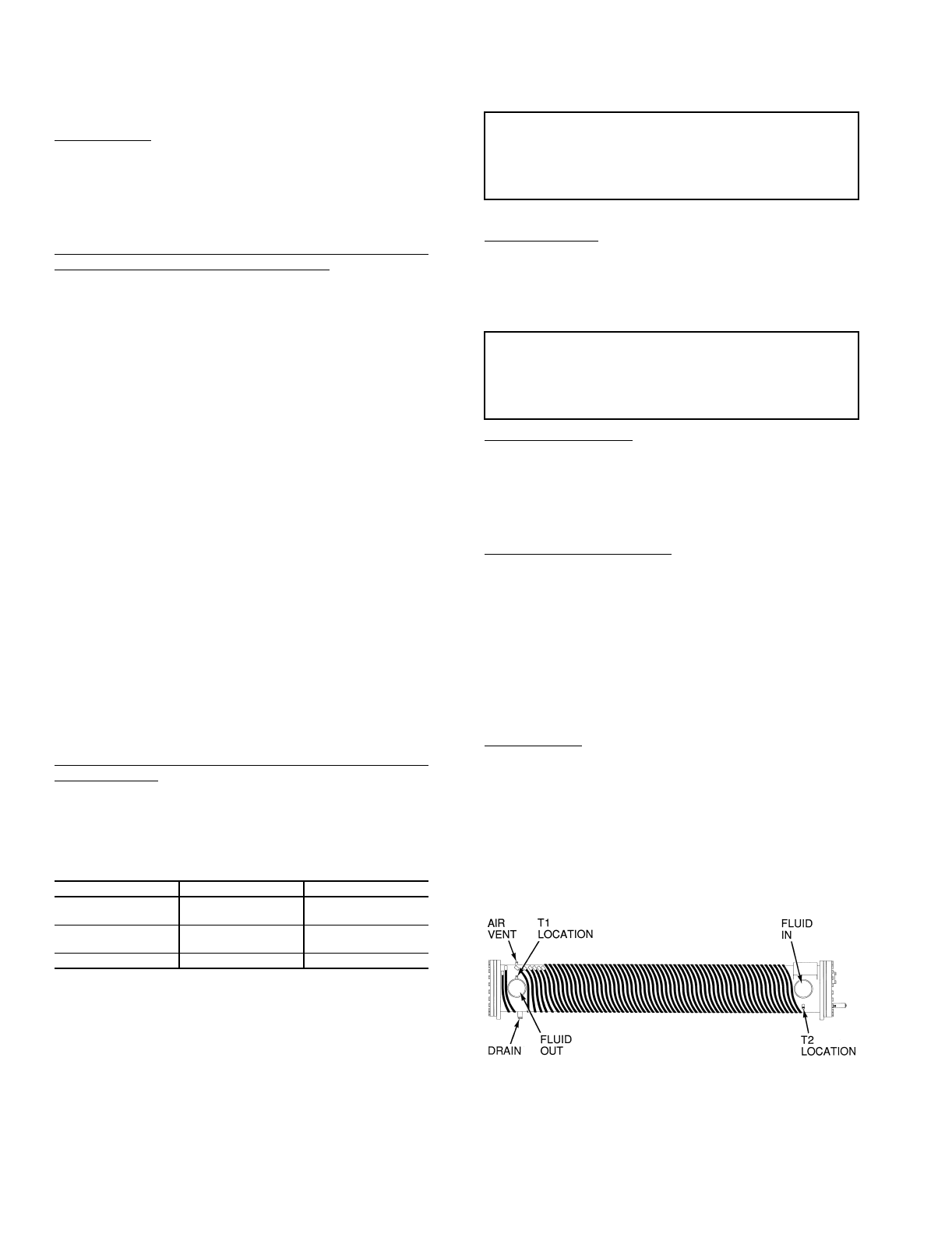
64
Safety Devices — Chillers contain many safety devices
and protection logic built into electronic control. Following is a
brief summary of major safeties.
COMPRESSOR PROTECTION
Circuit Breaker — One manual-reset, calibrated-trip magnetic
circuit breaker for each compressor protects against overcur-
rent. Do not bypass or increase size of a breaker to correct
problems. Determine cause for trouble and correct before
resetting breaker. Circuit breaker must-trip amps (MTA) are
listed on individual circuit breakers, and on unit label
diagrams.
30GTN,R and 30GUN,R070 (50 Hz), 080-110 and 230B-
315B Compressor Protection Board (CPCS) — The CPCS is
used to control and protect compressors and crankcase heaters.
Board provides following features:
•compressor contactor control
•crankcase heater control
•ground current protection
•status communication to processor board
•high-pressure protection
One large relay is located on CPCS that controls crankcase
heater and compressor contactor. In addition, this relay pro-
vides a set of contacts that the microprocessor monitors to de-
termine operating status of compressor. If the MBB determines
that compressor is not operating properly through signal con-
tacts, control locks compressor off.
The CPCS contains logic that can detect if current-to-
ground of any winding exceeds 2.5 amps; if so, compressor
shuts down.
A high-pressure switch with a trip pressure of 426 ± 7 psig
(2936 ± 48 kPa) is mounted on each compressor; switch setting
is shown in Table 34. Switch is wired in series with the CPCS.
If switch opens, CPCS relay opens, processor detects it through
signal contacts, and compressor locks off. A loss-of-charge
switch is also wired in series with the high-pressure switch and
CPCS.
If any of these switches opens during operation, the com-
pressor stops and the failure is detected by the MBB when sig-
nal contacts open. If lead compressor in either circuit is shut
down by high-pressure switch, ground current protector, loss of
charge switch, or oil pressure switch, all compressors in the cir-
cuit are locked off.
30GTN,R and 30GUN,R 130-210, 230A-315A and
330A/B-420A/B — A control relay in conjunction with a
ground fault module replaces the function of the CPCS
(above). To reset, press the push-button switch (near the Mar-
quee display).
Table 34 — Pressure Switch Settings,
psig (kPa)
LOW OIL PRESSURE PROTECTION — Lead compres-
sor in each circuit is equipped with a switch to detect low oil
pressure. Switch is connected directly to processor board.
Switch is set to open at approximately 5 psig (35 kPa) and to
close at 9 psig (62 kPa) maximum. If switch opens when
compressor is running, CR or processor board stops all com-
pressors in circuit. During start-up, switch is bypassed for
2 minutes.
CRANKCASE HEATERS — Each compressor has a 180-w
crankcase heater to prevent absorption of liquid refrigerant by
oil in crankcase when compressor is not running. Heater power
source is auxiliary control power, independent of main unit
power. This assures compressor protection even when main
unit power disconnect switch is off.
COOLER PROTECTION
Freeze Protection — Cooler can be wrapped with heater
cables as shown in Fig. 34, which are wired through an ambi-
ent temperature switch set at 36 F (2 C). Entire cooler is cov-
ered with closed-cell insulation applied over heater cables.
Heaters plus insulation protect cooler against low ambient tem-
perature freeze-up to 0° F (–18 C).
Low Fluid Temperature — Main Base Board is programmed
to shut chiller down if leaving fluid temperature drops below
34 F (1.1 C) for water or more than 8° F (4.4° C) below set
point for brine units. The unit will shut down without a
pumpout. When fluid temperature rises to 6° F (3.3° C) above
leaving fluid set point, safety resets and chiller restarts. Reset is
automatic as long as this is the first occurrence.
Loss of Fluid Flow Protection — Main Base Board contains
internal logic that protects cooler against loss of cooler flow.
Entering and leaving fluid temperature sensors in cooler detect
a no-flow condition. Leaving sensor is located in leaving fluid
nozzle and entering sensor is located in first cooler baffle space
in close proximity to cooler tubes, as shown in Fig. 34. When
there is no cooler flow and the compressors start, leaving fluid
temperature does not change. However, entering fluid temper-
ature drops rapidly as refrigerant enters cooler through EXV.
Entering sensor detects this temperature drop and when enter-
ing temperature is 3° F (1.6° C) below leaving temperature,
unit stops and is locked off.
Loss-of-Charge — A pressure switch connected to high side
of each refrigerant circuit protects against total loss-of-charge.
Switch settings are listed in Table 34. If switch is open, unit
cannot start; if it opens during operation, unit locks out and
cannot restart until switch is closed. Low charge is also moni-
tored by the processor when an EXV is used. The loss-of-
charge switch is wired in series with the high-pressure switch
on each circuit’s lead compressor.
SWITCH CUTOUT CUT-IN
High Pressure
30GTN,R Units
426 ± 7
(2936 ± 48)
320 ± 20
(2205 ± 138)
High Pressure
30GUN,R Units
280 ± 10
(1830 ± 69)
180 ± 20
(1240 ± 138)
Loss-of-Charge 7 (48.2) 22 (151.6)
IMPORTANT: Never open any switch or disconnect
that deenergizes crankcase heaters unless unit is being
serviced or is to be shut down for a prolonged period.
After a prolonged shutdown or service, energize crank-
case heaters for 24 hours before starting unit.
IMPORTANT: If unit is installed in an area where ambi-
ent temperatures fall below 32 F (0° C), it is recom-
mended that inhibited ethylene glycol or other suitable
corrosion-inhibitive antifreeze solution be used in
chilled-liquid circuit.
LEGEND
T — Thermistor
Fig. 34 — Cooler Heater Cables
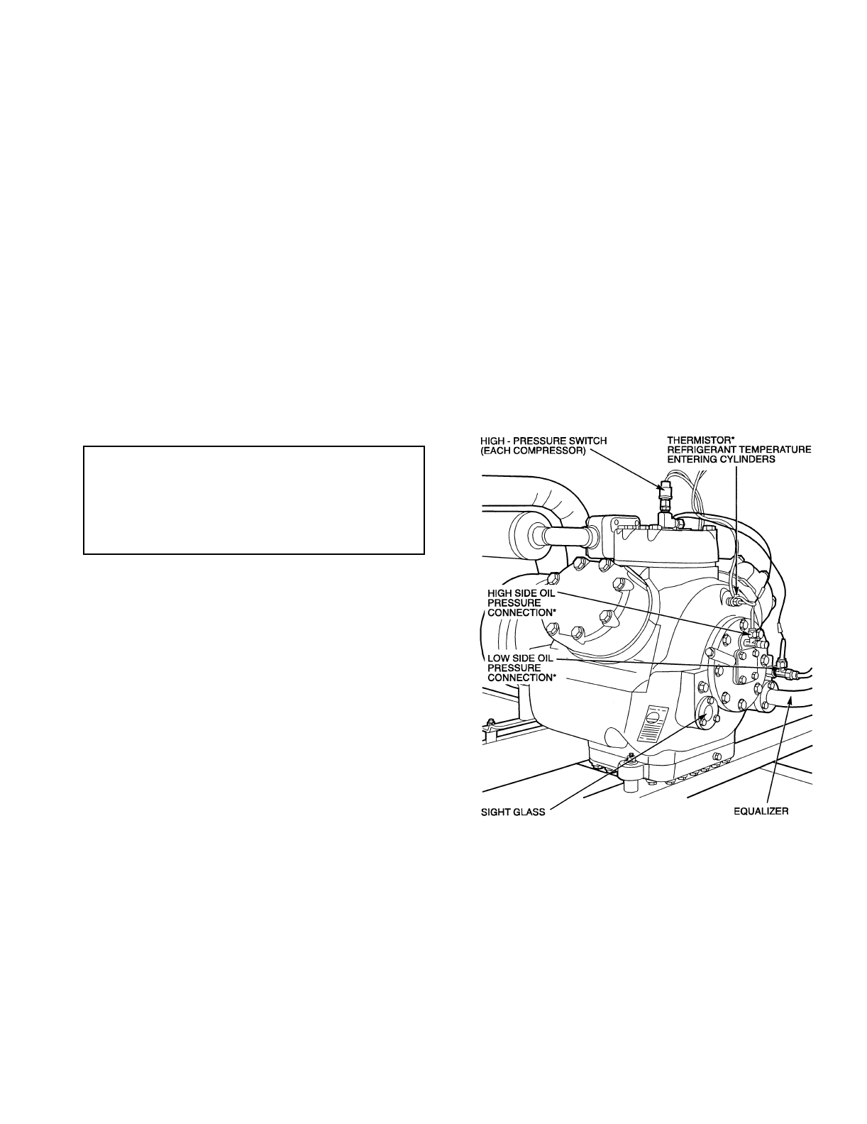
65
Relief Devices — Fusible plugs are located in each cir-
cuit to protect against damage from excessive pressures.
HIGH-SIDE PROTECTION — One device is located
between condenser and filter drier; a second is on filter drier.
These are both designed to relieve pressure on a temperature
rise to approximately 210 F (99 C).
LOW-SIDE PROTECTION — A device is located on suc-
tion line and is designed to relieve pressure on a temperature
rise to approximately 170 F (77 C).
PRESSURE RELIEF VALVES (208/230, 460, 575 v;
60 Hz Units Only) — Valves are installed in each circuit (one
per circuit). The valves are designed to relieve at 450 psig
(3103 kPa). These valves should not be capped. If a valve
relieves, it should be replaced. If valve is not replaced, it may
relieve at a lower pressure, or leak due to trapped dirt from the
system which may prevent resealing.
The pressure relief valves are equipped with a 3/8-in. SAE
flare for field connection. Some local building codes require
that relieved gases be removed. This connection will allow
conformance to this requirement.
Other Safeties — There are several other safeties that are
provided by microprocessor control. For details refer to
Alarms and Alerts section on page 48.
PRE-START-UP
Do not attempt to start the chiller until following checks
have been completed.
System Check
1. Check all auxiliary components, such as the chilled
fluid circulating pump, air-handling equipment, or
other equipment to which the chiller supplies liquid.
Consult manufacturer’s instructions. If the unit
has field-installed accessories, be sure all are properly
installed and wired correctly. Refer to unit wiring
diagrams.
2. Backseat (open) compressor suction and discharge shut-
off valves. Close valves one turn to allow refrigerant pres-
sure to reach the test gages.
3. Open liquid line service valves.
4. Fill the chiller fluid circuit with clean water (with
recommended inhibitor added) or other noncorrosive flu-
id to be cooled. Bleed all air out of high points of system.
An air vent is included with the cooler. If outdoor temper-
atures are expected to be below 32 F (0° C), sufficient in-
hibited ethylene glycol or other suitable corrosion-inhibit-
ed antifreeze should be added to the chiller water circuit
to prevent possible freeze-up.
5. Check tightness of all electrical connections.
6. Oil should be visible in the compressor sight glass. See
Fig. 35. An acceptable oil level in the compressor is from
1/8 in. to 3/8 in. of sight glass. Adjust the oil level as re-
quired. No oil should be removed unless the crankcase
heater has been energized for at least 24 hours. See Oil
Charge section on page 53 for Carrier-approved oils.
7. Electrical power source must agree with unit nameplate.
8. Crankcase heaters must be firmly locked into compres-
sors, and must be on for 24 hours prior to start-up.
9. Fan motors are 3 phase. Check rotation of fans during the
service test. Fan rotation is clockwise as viewed from top
of unit. If fan is not turning clockwise, reverse 2 of the
power wires. For low noise fan option on 50 Hz chillers,
fans rotate counterclockwise as viewed from top of unit.
If fan is not turning counterclockwise, reverse 2 of the
power wires.
10. Check compressor suspension. Mounting rails must be
floating freely on the springs.
11. Perform service test to verify proper settings.
IMPORTANT: Before beginning Pre-Start-Up or Start-
Up, complete Start-Up Checklist for ComfortLink™
Chiller Systems at end of this publication (page CL-1).
The Checklist assures proper start-up of a unit, and
provides a record of unit condition, application require-
ments, system information, and operation at initial
start-up.
*Lead compressor only.
Fig. 35 — Compressor Connections
(Lead Compressor Shown)
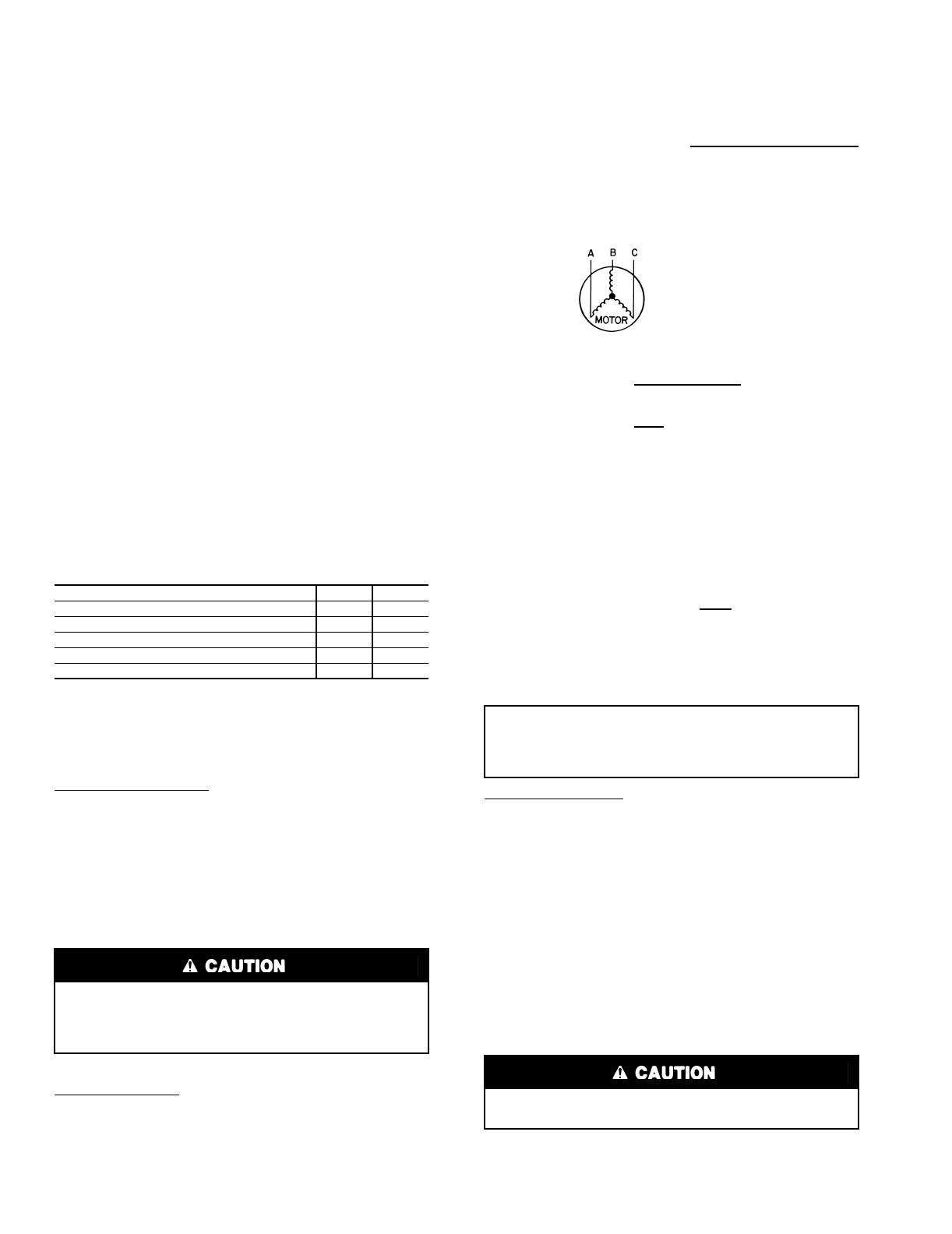
66
START-UP AND OPERATION
NOTE: Refer to Start-Up Checklist on pages CL-1 to CL-8.
Actual Start-Up — Actual start-up should be done only
under supervision of a qualified refrigeration mechanic.
1. Be sure all service valves are open. Units are shipped
from factory with suction, discharge, and liquid line
service valves closed.
2. Using the Marquee display, set leaving-fluid set point
(CSP.1 is Set Point mode under sub-mode COOL). No
cooling range adjustment is necessary.
3. If optional control functions or accessories are being
used, the unit must be properly configured. Refer to Op-
erating Data section for details.
4. Start chilled fluid pump.
5. Turn ENABLE/OFF/REMOTE CONTACT switch to
ENABLE position.
6. Allow unit to operate and confirm that everything is func-
tioning properly. Check to see that leaving fluid tempera-
ture agrees with leaving set point (CSP.1 or CSP.2), or if
reset is used, with the control point (CTPT) in the Run
Status mode under the sub-mode VIEW.
Operating Limitations
TEMPERATURES (See Table 35) — If unit is to be used in
an area with high solar radiation, mounted position should be
such that control box is not exposed to direct solar radiation.
Exposure to direct solar radiation could affect the temperature
switch controlling cooler heaters.
Table 35 — Temperature Limits for Standard Units
LEGEND
*For sustained operation, EWT should not exceed 85 F (29.4 C).
†Unit requires modification below this temperature.
Low-Ambient Operation — If operating temperatures below
0° F (–18 C) are expected, refer to separate installation instruc-
tions for low-ambient operation using accessory Motor-
master® III control. Contact your Carrier representative for
details.
NOTE: Wind baffles and brackets must be field-fabricated for
all units using accessory Motormaster III controls to ensure
proper cooling cycle operation at low-ambient temperatures.
See Installation Instructions shipped with the Motormaster III
accessory for more details.
VOLTAGE
Main Power Supply — Minimum and maximum acceptable
supply voltages are listed in the Installation Instructions.
Unbalanced 3-Phase Supply Voltage — Never operate a motor
where a phase imbalance between phases is greater than 2%.
To determine percent voltage imbalance:
The maximum voltage deviation is the largest difference
between a voltage measurement across 2 legs and the average
across all 3 legs.
Example: Supply voltage is 240-3-60.
AB = 243 v
BC = 236 v
AC = 238 v
1. Determine average voltage:
2. Determine maximum deviation from average voltage:
(AB) 243 – 239 = 4 v
(BC) 239 – 236 = 3 v
(AC) 239 – 238 = 1 v
Maximum deviation is 4 v.
3. Determine percent voltage imbalance:
This voltage imbalance is satisfactory as it is below the
maximum allowable of 2%.
Control Circuit Power — Electronic control includes logic to
detect low control circuit voltage. Acceptable voltage ranges
are shown in the Installation Instructions.
MINIMUM FLUID LOOP VOLUME — To obtain proper
temperature control, loop fluid volume must be at least 3 gal-
lons per ton (3.25 L per kW) of chiller nominal capacity for air
conditioning and at least 6 gallons per ton (6.5 L per kW) for
process applications or systems that must operate at low ambi-
ent temperatures (below 32 F [0° C]). Refer to application
information in Product Data literature for details.
FLOW RATE REQUIREMENTS — Standard chillers
should be applied with nominal flow rates approximating those
listed in Table 36. Higher or lower flow rates are permissible to
obtain lower or higher temperature rises. Minimum flow rates
must be exceeded to assure turbulent flow and proper heat
transfer in the cooler.
TEMPERATURE F C
Maximum Ambient Temperature 125 52
Minimum Ambient Temperature 0–18
Maximum Cooler EWT* 95 35
Maximum Cooler LWT 70 21
Minimum Cooler LWT†38 3.3
EWT —Entering Fluid (Water) Temperature
LWT —Leaving Fluid (Water) Temperature
Brine duty application (below 38 F [3.3 C] LCWT) for
chiller normally requires factory modification. Contact
your Carrier representative for applicable LCWT range for
standard water-cooled chiller in a specific application.
% Voltage Imbalance = 100 x max voltage deviation
from avg voltage
average voltage
Average voltage = 243 + 236 + 238
3
=717
3
=239
% Voltage Imbalance = 100 x 4
239
= 1.7%
IMPORTANT: If the supply voltage phase imbalance is
more than 2%, contact your local electric utility com-
pany immediately. Do not operate unit until imbalance
condition is corrected.
Operation below minimum flow rate could subject tubes to
frost pinching in tube sheet, resulting in failure of cooler.
67
Consult application data section in the Product Data litera-
ture and job design requirements to determine flow rate re-
quirements for a particular installation.
Table 36 — Nominal and Minimum Cooler
Fluid Flow Rates
LEGEND
*Nominal flow rates required at ARI conditions are 44 F (6.7 C) leaving-fluid
temperature, 54 F (12.2 C) entering-fluid temperature, 95 F(35 C) ambient.
Fouling factor is .00001 ft2 ⋅ hr ⋅ F/Btu (.000018 m2 ⋅ K/W).
NOTES:
1. Minimum flow based on 1.0 fps (0.30 m/s) velocity in cooler without special
cooler baffling.
2. Minimum Loop Volumes:
Gallons = V x ARI Cap. in tons
Liters = N x ARI Cap. in kW
Operation Sequence — During unit off cycle, crank-
case heaters are energized. If ambient temperature is below
36 F (2 C), cooler heaters (if equipped) are energized.
The unit is started by putting the ENABLE/OFF/REMOTE
CONTACT switch in ENABLE or REMOTE position. When
the unit receives a call for cooling (either from the internal
control or CCN network command or remote contact closure),
the unit stages up in capacity to maintain the cooler fluid set
point. The first compressor starts 11/2 to 3 minutes after the call
for cooling.
The lead circuit can be specifically designated or randomly
selected by the controls, depending on how the unit is field
configured (for 040-070 sizes, Circuit A leads unless an
accessory unloader is installed on Circuit B). A field configura-
tion is also available to determine if the unit should stage up
both circuits equally or load one circuit completely before
bringing on the other.
When the lead circuit compressor starts, the unit starts with
a pumpout routine. On units with the electronic expansion
valve (EXV), compressor starts and continues to run with the
EXV at minimum position for 10 seconds to purge the refriger-
ant lines and cooler of refrigerant. The EXV then moves to
23% and the compressor superheat control routine takes over,
modulating the valve to feed refrigerant into the cooler.
On units with thermostatic expansion valve (TXV)
(30GTN,R and 30GUN,R 040,045 units with brine option),
head pressure control is based on set point control. When the
lead compressor starts, the liquid line solenoid valve (LLSV) is
kept closed for 15 seconds by a time delay relay. The micropro-
cessor stages fans to maintain the set point temperature speci-
fied by the controller. There is no pumpout sequence during
shutdown of TXV controlled chillers.
On all other units (EXV units), the head pressure is con-
trolled by fan cycling. The desired head pressure set point is
entered, and is controlled by EXV position or saturated con-
densing temperature measurement (T3 and T4). For proper op-
eration, maintain set point of 113 F (45 C) as shipped from fac-
tory. The default head pressure control method is set point con-
trol. The head pressure control can also be set to EXV control
or a combination of the 2 methods between circuits.
For all units, if temperature reset is being used, the unit con-
trols to a higher leaving-fluid temperature as the building load
reduces. If demand limit is used, the unit may temporarily be
unable to maintain the desired leaving-fluid temperature be-
cause of imposed power limitations.
On EXV units, when the occupied period ends, or when the
building load drops low enough, the lag compressors shut
down. The lead compressors continue to run as the EXV clos-
es, and until the conditions of pumpout are satisfied. If a fault
condition is signaled requiring immediate shutdown, pumpout
is omitted.
Loading sequence for compressors is shown in Tables 5A
and 5B.
Refrigerant Circuit
LEAK TESTING — Units are shipped with complete operat-
ing charge of refrigerant R-22 for 30GTN,R and R-134a for
30GUN,R (see Physical Data tables supplied in the chiller’s
installation instructions) and should be under sufficient pres-
sure to conduct a leak test. If there is no pressure in the system,
introduce enough nitrogen to search for the leak. Repair the
leak using good refrigeration practices. After leaks are
repaired, system must be evacuated and dehydrated.
REFRIGERANT CHARGE (Refer to Physical Data tables
supplied in the chiller’s installation instructions) — Immedi-
ately ahead of filter drier in each circuit is a factory-installed
liquid line service valve. Each valve has a 1/4-in. Schrader con-
nection for charging liquid refrigerant.
Charging with Unit Off and Evacuated — Close liquid line
service valve before charging. Weigh in charge shown on unit
nameplate (also in Physical Data tables supplied in the chiller’s
installation instructions). Open liquid line service valve; start
unit and allow it to run several minutes fully loaded. Check for
a clear sight glass. Be sure clear condition is liquid and not
vapor.
Charging with Unit Running — If charge is to be added while
unit is operating, all condenser fans and compressors must be
operating. It may be necessary to block condenser coils at low
ambient temperatures to raise condensing pressure to approxi-
mately 280 psig (1931 kPa) to turn all condenser fans on. Do
not totally block a coil to do this. Partially block all coils in uni-
form pattern. Charge each circuit until sight glass shows clear
liquid, then weigh in amount over a clear sight glass as listed
in Physical data tables supplied in chiller’s installation
instructions.
FIELD WIRING
Field wiring is shown in Fig. 36-41.
UNIT SIZE
30GTN,R
AND 30GUN,R
NOMINAL
FLOW RATE*
MINIMUM
FLOW RATE
(See Notes)
Gpm L/s Gpm L/s
040 86 5.43 36.8 2.32
045 101 6.3737.72.38
050 123 7.7637.72.38
060 151 9.5347.53.00
070 173 10.91 47.5 3.00
080,230B 192 12.11 66.7 4.20
090,245B 216 13.62 59.5 3.75
100,255B,270B 240 15.14 84.1 5.30
110,290B,315B 264 16.65 84.1 5.30
130 30018.9110 6.9
150,230A-255A 34821.9110 6.9
170,270A,330A/B,
360B (50 Hz) 38424.2120 7.5
190,290A,360A/B (60 Hz),
360A (50 Hz), 390B 43227.2120 7.5
210,315A,390A,420A/B 48030.2148 9.3
ARI —Air Conditioning and Refrigeration Institute
Gpm —Gallons per minute (U.S.)
L/s —Liters per second
N—Liters per kW
V—Gallons per ton
APPLICATION V N
Normal Air Conditioning 33.25
Process Type Cooling 6 to 10 6.5 to 10.8
Low Ambient Unit Operation 6 to 10 6.5 to 10.8
IMPORTANT: When adjusting refrigerant charge, circu-
late fluid through cooler continuously to prevent freez-
ing and possible damage to the cooler. Do not
overcharge, and never charge liquid into low-pressure
side of system.
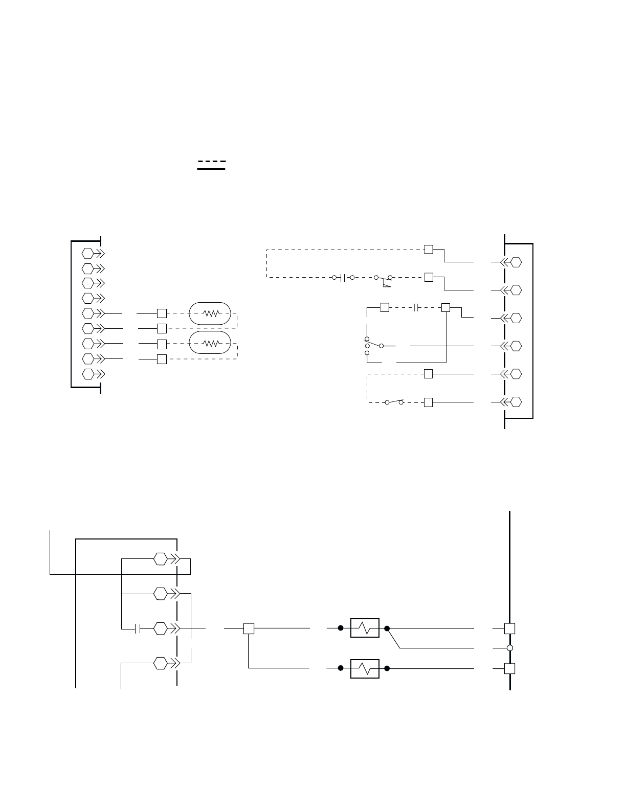
68
LEGEND FOR FIG. 36-41
ALM —Alarm
CWFS —Chilled Water Flow Switch
CWP —Chilled Water Pump
CWPI —Chilled Water Pump Interlock
CXB —Compressor Expansion Board
HGBPS —Hot Gas Bypass Switch
LWT —Leaving Fluid Temperature
MBB —Main Base Board
OAT —Outdoor-Air Temperature Sensor
SPT —Remote Space Temperature Sensor
SW —Switch
TB —Terminal Block
UL —Unloader
Field Supplied Wiring
Factory Wiring
11
2
2
33
4
4
5
5
6
6
7
7
8
8
9
9
MBB,
PLUG J8
5
6
7
8
BLU
BLU
PNK
PNK
TB5
TB5
TB5
TB5
SPT ACCESSORY
OAT ACCESSORY OR
DUAL CHILLER LWT.
(MASTER CHILLER)
T9
T10
10
9
9
10
8
7
6
6
7
8
5
5
GRA
RED
RED
GRA
ORN
ORN
TB5
14
4
3
TB5
TB5
DUAL SETPOINT
TB5
RED
RED
A
C
B
13
RED
OFF
REMOTE
CONTACT
SW1
ENABLE
REMOTE
ON-OFF SWITCH
TB5
TB5
2
1
CWFS
MBB,
PLUG J7
CWPI
1
VIO
VIO
HGBPS-B
HGBPS-A
GRA 12 TB5
HGBPS-B
12 TB5
GRA
GRA
TB5
9
GRA
BLK
4
2
33
4
1
2
K11
MAIN BASE BOARD
J10A
PLUG
Fig. 36 — Accessory Sensor
Control Wiring
Fig. 37 — Control Wiring (24 V)
Fig. 38 — Hot Gas Bypass Control Wiring (115 V, 230 V)
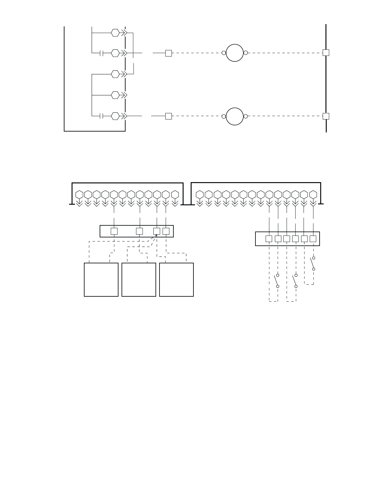
69
VIO
BLK
4
3
2
J10B
PLUG
MBB
15
16
17
18
19
K8
K7
5
6TB5
10
TB5
BLK 11 12 TB5
12 TB5
ALM
R
CWP
R
MAX LOAD-75VA SEALED
360VA INRUSH
MAX LOAD-75VA SEALED
360VA INRUSH
12 111098765432 1 111098765432 1
14 13 12
EMM, PLUG J6 EMM, PLUG J7
TB6 3251
PNK ORN BRN VIO
121110987654321 14131211109876543 21
TB6 15 14 13 12 10 9
BLU RED GRA
BLU RED GRA
FIELD SUPPLIED
DRY CONTACTS 24V
COOLING
SETPOINT
TEMPERATURE
RESET DEMAND
LIMIT
4.20 MA
SIGNAL
GENERATOR
4.20 MA
SIGNAL
GENERATOR
4.20 MA
SIGNAL
GENERATOR
-+-+-+
ICE DONE
DEMAND LIMIT STEP 2
DEMAND LIMIT STEP 1
Fig. 39 — Chilled Water Pump Control Wiring and Remote Alarm 115 V Relay Wiring
Fig. 40 — Energy Management Module (EMM) Wiring
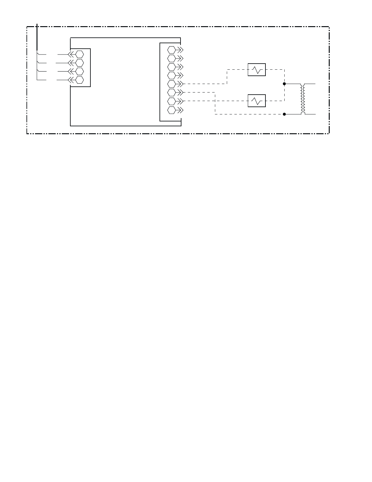
70
1
2
3
4
1
2
3
4
5
6
7
8
5
6
7
8
4
3
2
1
4
3
2
1
GND
BLK
WHT
RED
UL-A2
UL-B2
24V 115V/
230V
CXB ACCESSORY CXB ACCESSORY
J4 J6
CXB
BOARD
Fig. 41 — Compressor Expansion Board (CXB) Accessory Wiring
71
APPENDIX A — CCN TABLES
UNIT (Configuration Settings)
OPTIONS1 (Options Configuration)
*Unit size dependent.
DESCRIPTION STATUS DEFAULT UNITS POINT
1Unit Type 1 = Air Cooled
2 = Water Cooled
3 = Split System
4 = Heat Machine
5 = Air Cooled Heat Reclaim
1 UNIT_TYP
2Unit Size 20 to 300 * TONS SIZE
3Circuit A1% Capacity 0 to 100 * % CAP_A
4 Number Circ A Compressor 1 to 4 * NUMCA
5 Compressor A1 Cylinders 4 or 6 * NUM_CYLA
6 Number Circ B Compressor 1 to 4 * NUMCB
7 Compressor B1 Cylinders 4 or 6 * NUM_CYLB
8 EXV Module Installed No/Yes Yes EXV_BRD
9 EXV Superheat Setpoint 10 to 40 29.0 (30GTN,R)
23.0 (30GUN,R)
^F SH_SP
10 EXV MOP 40 to 80 50.0 °FMOP_SP
11 EXV Superheat Offset –20 to 20 0.0 ^F SH_OFFST
12 EXV Circ. A Min Position 0 to 100 8.0 % EXVAMINP
13 EXV Circ. B Min Position 0 to 100 8.0 % EXVBMINP
14 Refrigerant 1 = R22
2 = R134A
1 (30GTN,R)
2 (30GUN,R)
REFRIG_T
15 Low Pressure Setpoint 3 to 60 10.0 PSI LOW_PRES
16 Fan Staging Select 1 = 2 Stage indpt.
2 = 3 Stage indpt.
3 = 2 Stage common
4 = 3 Stage common
* FAN_TYPE
DESCRIPTION STATUS DEFAULT POINT
1Cooler Fluid 1 = Water
2 = Med. Brine
3 = Low Brine
1FLUIDTYP
2Hot Gas Bypass Select No/Yes No HGBV_FLG
3Head Press. Cont. Method 1 = EXV controlled
2 = Setpoint control
3 = Setpoint-A, EXV-B
4 = EXV-A, Setpoint-B
2HEAD_MET
4Head Press. Control Type 0 = None
1 = Air Cooled
2 = Water Cooled
1HEAD_TYP
5Motormaster Select No/Yes No MTR_TYPE
6Pressure Transducers Off/On Off PRESS_TY
8Cooler Pump Control Off/On Off CPC
9Condenser Pump Interlock Off/On Off CND_LOCK
10 Condenser Pump Control 0 = No control
1 = On with Mode
2 = On with Compressors
0 CNPC
11 Condenser Fluid Sensors No/Yes No CD_TEMP
12 No. Circuit A Unloaders 0-2 * NUNLA
13 No. Circuit B Unloaders 0-2 * NUNLB
14 EMM Module Installed No/Yes No EMM_BRD
72
APPENDIX A — CCN TABLES (cont)
CONFIGURATION SCREEN (TYPE 10)
OPTIONS2 (Options Configuration)
DISPLAY (STDU SETUP)
SCHEDOVR (TIMED OVERRIDE SETUP)
ALARMDEF (Alarm Definition Table)
*Unit size dependent.
DESCRIPTION STATUS DEFAULT UNITS POINT
1Control Method 0 = Switch
1 = 7 day sched.
2 = Occupancy
3 = CCN
0 CONTROL
2Loading Sequence Select 1 = Equal loading
2 = Staged loading
1 SEQ_TYPE
3Lead/Lag Circuit Select 1 = Automatic
2 = Circuit A leads
3 = Circuit B leads
*LEAD_TYP
4Cooling Setpoint Select 0 = Single
1 = Dual, remote switch controlled
2 = Dual, 7-day occupancy
3 = Dual CCN occupancy
4 = 4-20 mA input
5 = External POT
0CLSP_TYP
5Heating Setpoint Select 0 = Single
1 = Dual, remote switch controlled
2 = Dual, 7 day occupancy
3 = Dual CCN occupancy
4 = 4-20 mA input
0HTSP_TYP
6Ramp Load Select Enable/Disable Disable RAMP_EBL
7Heat Cool Select Cool/Heat Cool HEATCOOL
8High LCW Alert Limit 2 to 60 60.0 ^F LCW_LMT
9Minutes off time 0 to 15 0 min DELAY
10 Deadband Multiplier 1.0 to 4.0 1.0 Z_GAIN
11 Ice Mode Enable Enable/Disable Disable ICE_CNFG
DESCRIPTION STATUS DEFAULT UNITS POINT
1Service Password nnnn 1111 PASSWORD
2Password Enable Enable/Disable Enable PASS_EBL
3Metric Display Off/On Off DISPUNIT
4Language Selection 0 = ENGLISH
1 = FRANCAIS
2 = ESPANOL
3 = PORTUGUES
0LANGUAGE
DESCRIPTION STATUS DEFAULT UNITS POINT
1Schedule Number 0-99 0 SCHEDNUM
2Override Time Limit 0-4 0 hours OTL
3Timed Override Hours 0-4 0 hours OTL_EXT
4Timed Override Yes/No No TIMEOVER
DESCRIPTION STATUS DEFAULT UNITS POINT
1Alarm Routing Control 00000000 00000000 ALRM_CNT
2Equipment Priority 0 to 7 4 EQP_TYPE
3Comm Failure Retry Time 1 to 240 10 min RETRY_TM
4Re-alarm Time 1 to 255 30 min RE-ALARM
5Alarm System Name XXXXXXXX Chiller ALRM_NAM
73
APPENDIX A — CCN TABLES (cont)
RESETCON (Temperature Reset and Demand Limit)
BRODEFS (Broadcast POC Definition Table)
DESCRIPTION STATUS DEFAULT UNITS POINT
1COOLING RESET
2Cooling Reset Type 0 = No Reset
1 = 4-20 ma input
2 = External temp-OAT
3 = Return fluid
4 = External temp-SPT
0 CRST_TYP
3No Cool Reset Temp 0 to 125 125.0 °FCT_NO
4Full Cool Reset Temp 0 to 125 0.0 °F CT_FULL
5Degrees Cool Reset –30 to 30 0.0 ^F CT_DEG
6
7HEATING RESET
8Heating Reset Type 0 = No Reset
1 = 4-20 ma input
2 = External temp — OAT
3 = Return fluid
4 = External temp — SPT
0 HRST_TYP
9No Heat Reset Temp 0 to 125 0.0 HT_NO
10 Full Heat Reset Temp 0 to 125 125.0 % HT_FULL
11 Degrees Heat Reset –30 to 30 0.0 min HT_DEG
12
13 DEMAND LIMIT
14 Demand Limit Select 0 = None
1 = External switch input
2 = 4-20 ma input
3 = Loadshed
0DMD_CTRL
15 Demand Limit at 20 mA 0 to 100 100 % DMT20MA
16 Loadshed Group Number 0 to 99 0 SHED_NUM
17 Loadshed Demand Delta 0 to 60 0 % SHED_DEL
18 Maximum Loadshed Time 0 to 120 60 min SHED_TIM
19 Demand Limit Switch 1 0 to 100 80 % DLSWSP1
20 Demand Limit Switch 2 0 to 100 50 % DLSWSP2
21
22 LEAD/LAG
23 Lead/Lag Chiller Enable Enable/Disable Disable LL_ENA
24 Master/Slave Select Slave/Master Master MS_SEL
25 Slave Address 0 to 239 0 SLV_ADDR
26 Lead/Lag Balance Select Enable/Disable Disable LL_BAL
27 Lead/Lag Balance Delta 40 to 400 168 hours LL_BAL_D
28 Lag Start Delay 0 to 30 5 mins LL_DELAY
DESCRIPTION STATUS DEFAULT UNITS POINT
1CCN Time/Date Broadcast Yes/No No CCNBC
2CCN OAT Broadcast Yes/No No OATBC
3Global Schedule Broadcast Yes/No No GSBC
4CCN Broadcast Acker Yes/No No CCNBCACK
5Daylight Savings Start
6Month 1 to 12 4 STARTM
7Week 1 to 5 1 STARTW
8Day 1 to 7 7 STARTD
9Minutes to add 0 to 99 60 min MINADD
10 Daylight Savings Stop
11 Month 1 to 12 10 STOPM
12 Week 1 to 5 5 STOPW
13 Day 1 to 7 7 STOPD
14 Minutes to subtract 0 to 99 60 min MINSUB
74
APPENDIX A — CCN TABLES (cont)
A_UNIT (General Unit Parameters)
CIRCA_AN (Circuit A Analog Parameters)
CIRCA_DIO (Circuit A Discrete Parameters)
DESCRIPTION STATUS UNITS POINT FORCEABLE
1Control Mode 0 = Service
1 = OFF - local
2 = OFF-CCN
3 = OFF-time
4 = Emergency
5 = ON-local
6 = ON-CCN
7 = ON-time
STAT N
2Occupied Yes/No OCC N
3CCN Chiller Start/Stop CHIL_S_S Y
4Alarm State Normal ALM N
5Active Demand Limit 0-100 % DEM_LIM Y
6Override Modes in Effect Yes/No MODE N
7Percent Total Capacity 0-100 % CAP_T N
8Requested Stage nn STAGE N
9Active Setpoint snnn.n °FSP N
10 Control Point snnn.n °F CTRL_PNT Y
11 Entering Fluid Temp snnn.n °FEWT N
12 Leaving Fluid Temp snnn.n °FLWT N
13 Emergency Stop Enable/Emstop EMSTOP Y
14 Minutes Left for Start nn min MIN_LEFT N
15 Heat Cool Select Heat/Cool HEATCOOL Y
DESCRIPTION STATUS UNITS POINT FORCEABLE
1Circuit A Analog Values
2Percent Total Capacity 0-100 % CAPA_T N
3Percent Available Cap 0-100 % CAPA_A N
4Discharge Pressure nnn.n PSI DP_A N
5Suction Pressure nnn.n PSI SP_A N
6Saturated Condensing Tmp snnn.n °FTMP_SCTA N
7Saturated Suction Temp snnn.n °FTMP_SSTA N
8Compressor Suction Temp snnn.n °FCTA_TMP N
9Suction Superheat Temp snnn.n ^F SH_A N
10 EXV % Open 0-100.0 % EXV_A N
DESCRIPTION STATUS UNITS POINT FORCEABLE
1CIRC. A DISCRETE OUTPUTS
2Compressor A1 Relay ON/OFF K_A1_RLY N
3Compressor A2 Relay ON/OFF K_A2_RLY N
4Compressor A3 Relay ON/OFF K_A3_RLY N
5Compressor A4 Relay ON/OFF K_A4_RLY N
6Unloader A1 Relay ON/OFF UNL_A1 N
7Unloader A2 Relay ON/OFF UNL_A2 N
8Liq. Line Solenoid Valve OPEN/CLOSE LLSV_A N
9Hot Gas Bypass Relay ON/OFF HGB N
10
11 CIRC. A DISCRETE INPUTS
12 Compressor A1 Feeback ON/OFF K_A1_FBK N
13 Compressor A2 Feedback ON/OFF K_A2_FBK N
14 Compressor A3 Feedback ON/OFF K_A3_FBK N
15 Compressor A4 Feedback ON/OFF K_A4_FBK N
16 Oil Pressure Switch A OPEN/CLOSE OILSW_A N
17 Low Pressure Switch A OPEN/CLOSE LPS_A N
75
APPENDIX A — CCN TABLES (cont)
CIRCB_AN (Circuit B Analog Parameters)
CIRCBDIO (Circuit B Discrete Parameters)
DESCRIPTION STATUS UNITS POINT FORCEABLE
1Circuit B Analog Values
2Percent Total Capacity 0-100 % CAPB_T N
3Percent Available Cap 0-100 % CAPB_A N
4Discharge Pressure nnn.n PSI DP_B N
5Suction Pressure nnn.n PSI SP_B N
6Saturated Condensing Tmp snnn.n °FTMP_SCTB N
7Saturated Suction Temp snnn.n °FTMP_SSTB N
8Compressor Suction Temp snnn.n °FCTB_TMP N
9Suction Superheat Temp snnn.n ^F SH_B N
10 EXV % Open 0-100.0 % EXV_B N
DESCRIPTION STATUS UNITS POINT FORCEABLE
1CIRC. B DISCRETE OUTPUTS
2Compressor B1 Relay ON/OFF K_B1_RLY N
3Compressor B2 Relay ON/OFF K_B2_RLY N
4Compressor B3 Relay ON/OFF K_B3_RLY N
5Compressor B4 Relay ON/OFF K_B4_RLY N
6Unloader B1 Relay ON/OFF UNL_B1 N
7Unloader B2 Relay ON/OFF UNL_B2 N
8Liq. Line Solenoid Valve ON/OFF LLSV_B N
9Hot Gas Bypass Relay ON/OFF HGB N
10
11 CIRC. B DISCRETE INPUTS
12 Compressor B1 Feedback ON/OFF K_B1_FBK N
13 Compressor B2 Feedback ON/OFF K_B2_FBK N
14 Compressor B3 Feedback ON/OFF K_B3_FBK N
15 Compressor B4 Feedback ON/OFF K_B4_FBK N
16 Oil Pressure Switch B OPEN/CLOSE OILSW_B N
17 Low Pressure Switch B OPEN/CLOSE LPS_B N

76
APPENDIX A — CCN TABLES (cont)
OPTIONS (Unit Parameters)
DESCRIPTION STATUS UNITS POINT FORCEABLE
1FANS
2Fan 1 Relay ON/OFF FAN_1 N
3Fan 2 Relay ON/OFF FAN_2 N
4Fan 3 Relay ON/OFF FAN_3 N
5Fan 4 Relay ON/OFF FAN_4 N
6
7UNIT ANALOG VALUES
8Cooler Entering Fluid snnn.n °F COOL_EWT N
9Cooler Leaving Fluid snnn.n °F COOL_LWT N
10 Condensing Entering Fluid snnn.n °F COND_EWT N
11 Condenser Leaving Fluid snnn.n °F COND_LWT N
12 Lead/Lag Leaving Fluid snnn.n °F DUAL_LWT N
13
14 TEMPERATURE RESET
15 4-20 mA Reset Signal nn.n mA RST_MA N
16 Outside Air Temperature snnn.n °FOAT Y
17 Space Temperature snnn.n °FSPT Y
18
19 DEMAND LIMIT
20 4-20 mA Demand Signal n.nn LMT_MA N
21 Demand Limit Switch 1 ON/OFF DMD_SW1 N
22 Demand Limit Switch 2 ON/OFF DMD_SW2 N
23 CCN Loadshed Signal 0 = Normal
1 = Redline
2 = Shed
OL_STAT N
24
25 PUMPS
26 Cooler Pump Relay ON/OFF COOL_PMP
27 Condenser Pump Relay ON/OFF COND_PMP N
28
29 MISCELLANEOUS
30 Dual Setpoint Switch ON/OFF DUAL_IN N
31 Cooler LWT Setpoint snn.n °FLWR_SP N
32 Cooler Flow Switch ON/OFF COOLFLOW N
33 Condenser Flow Switch ON/OFF CONDFLOW N
34 Ice Done ON/OFF ICE N
77
APPENDIX A — CCN TABLES (cont)
STRTHOUR
ALARMS
NOTE: Alerts will displayed as Txxx.
DESCRIPTION STATUS UNITS POINT
1Machine Operating Hours nnnnn hours HR_MACH
2Machine Starts nnnnn CY_MACH
3
4Circuit A Run Hours nnnnn hours HR_CIRA
5Compressor A1 Hours nnnnn hours HR_A1
6Compressor A2 Hours nnnnn hours HR_A2
7Compressor A3 Hours nnnnn hours HR_A3
8Compressor A4 Hours nnnnn hours HR_A4
9Circuit B Run Hours nnnnn hours HR_CIRB
10 Compressor B1 Hours nnnnn hours HR_B1
11 Compressor B2 Hours nnnnn hours HR_B2
12 Compressor B3 Hours nnnnn hours HR_B3
13 Compressor B4 Hours nnnnn hours HR_B4
14
15 Circuit A Starts nnnnn CY_CIRA
16 Compressor A1 Starts nnnnn CY_A1
17 Compressor A2 Starts nnnnn CY_A2
18 Compressor A3 Starts nnnnn CY_A3
19 Compressor A4 Starts nnnnn CY_A4
20 Circuit B Starts nnnnn CY_CIRB
21 Compressor B1 Starts nnnnn CY_B1
22 Compressor B2 Starts nnnnn CY_B2
23 Compressor B3 Starts nnnnn CY_B3
24 Compressor B4 Starts nnnnn CY_B4
DESCRIPTION STATUS UNITS POINT
1Active Alarm #1 Axxx or Txxx ALARM01C
2Active Alarm #2 Axxx or Txxx ALARM02C
3Active Alarm #3 Axxx or Txxx ALARM03C
4Active Alarm #4 Axxx or Txxx ALARM04C
5Active Alarm #5 Axxx or Txxx ALARM05C
6Active Alarm #6 Axxx or Txxx ALARM06C
7Active Alarm #7 Axxx or Txxx ALARM07C
8Active Alarm #8 Axxx or Txxx ALARM08C
9Active Alarm #9 Axxx or Txxx ALARM09C
10 Active Alarm #10 Axxx or Txxx ALARM10C
11 Active Alarm #11 Axxx or Txxx ALARM11C
12 Active Alarm #12 Axxx or Txxx ALARM12C
13 Active Alarm #13 Axxx or Txxx ALARM13C
14 Active Alarm #14 Axxx or Txxx ALARM14C
15 Active Alarm #15 Axxx or Txxx ALARM15C
16 Active Alarm #16 Axxx or Txxx ALARM16C
17 Active Alarm #17 Axxx or Txxx ALARM17C
18 Active Alarm #18 Axxx or Txxx ALARM18C
19 Active Alarm #19 Axxx or Txxx ALARM19C
20 Active Alarm #20 Axxx or Txxx ALARM20C
21 Active Alarm #21 Axxx or Txxx ALARM21C
22 Active Alarm #22 Axxx or Txxx ALARM22C
23 Active Alarm #23 Axxx or Txxx ALARM23C
24 Active Alarm #24 Axxx or Txxx ALARM24C
25 Active Alarm #25 Axxx or Txxx ALARM25C
78
APPENDIX A — CCN TABLES (cont)
CURRMODS
SETPOINT
LOADFACT
VERSIONS
DESCRIPTION STATUS UNITS POINT
1FSM controlling chiller ON/OFF MODE_1
2WSM controlling chiller ON/OFF MODE_2
3Master/Slave control ON/OFF MODE_3
4Low source protection ON/OFF MODE_4
5Ramp Load Limited ON/OFF MODE_5
6Timed Override in effect ON/OFF MODE_6
7Low Cooler Suction TempA ON/OFF MODE_7
8Low Cooler Suction TempB ON/OFF MODE_8
9Slow Change Override ON/OFF MODE_9
10 Minimum OFF Time ON/OFF MODE_10
11 Low Suction Superheat A ON/OFF MODE_11
12 Low Suction Superheat B ON/OFF MODE_12
13 Dual Setpoint ON/OFF MODE_13
14 Temperature Reset ON/OFF MODE_14
15 Demand Limit in effect ON/OFF MODE_15
16 Cooler Freeze Prevention ON/OFF MODE_16
17 Lo Tmp Cool/Hi Tmp Heat ON/OFF MODE_17
18 Hi Tmp Cool/Lo Tmp Heat ON/OFF MODE_18
19 Making Ice ON/OFF MODE_19
20 Storing Ice ON/OFF MODE_20
21 High SCT Circuit A ON/OFF MODE_21
22 High SCT Circuit B ON/OFF MODE_22
DESCRIPTION STATUS UNITS POINT DEFAULTS
1COOLING
2Cool Setpoint 1 –20 to 70 °FCSP1 44
3Cool Setpoint 2 –20 to 70 °FCSP2 44
4Ice Setpoint –20 to 32 °FCSP3 32
5
6HEATING
7Heat Setpoint 1 80 to 140 °F HSP1 100
8Heat Setpoint 2 80 to 140 °F HSP2 100
9
10 RAMP LOADING
11 Cooling Ramp Loading 0.2 to 2.0 °F/min CRAMP 1.0
12 Heating Ramp Loading 0.2 to 2.0 °F/min HRAMP 1.0
13
14 HEAD PRESSURE
15 Head Pressure Setpoint A 80 to 140 °F HSP_A 113
16 Head Pressure Setpoint B 80 to 140 °F HSP_B 113
DESCRIPTION STATUS UNITS POINT
1CAPACITY CONTROL
2Load/Unload Factor snnn.n % SMZ
3Control Point snnn.n °F CTRL_PNT
4Leaving Water Temp snnn.n °FLWT
DESCRIPTION STATUS UNITS POINT
1MBB CESR-131170 nn-nn
2EXV CESR-131172 nn-nn
3CXB CESR131173- nn-nn
4EMM CESR131174- nn-nn
5MARQ CESR131171- nn-nn
6NAV CESR131227- nn-nn
79
APPENDIX A — CCN TABLES (cont)
CSM/FSM EQUIPMENT TABLE (Type 621H, Block 2)
WSM EQUIPMENT PART COOL SOURCE MAINTENANCE TABLE
SUPERVISOR MAINTENANCE TABLE
OCCUPANCY MAINTENANCE TABLE
OCCUPANCY SUPERVISORY
LINE DESCRIPTION POINT
1Chiller Status
0 = Chiller is off
1 = Valid run state in CCN mode
2 = Recycle active
3 = Chiller is in Local Mode
4 = Power Fail Restart in Progress
5 = Shutdown due to fault
6 = Communication Failure
CHILSTAT
2Lag Status LAGSTAT
3Percent Total Capacity Running CAP_T
4Service Runtime HR_MACH
5unused
6unused
7unused
8Power Fail Auto Restart ASTART
9Percent Available Capacity On CAP_A
DESCRIPTION STATUS POINT
WSM Active? Yes WSMSTAT
Chilled water temp snn.n °F CHWTEMP
Equipment status On CHLRST
Commanded state Enable/Disable/None CHLRENA
CHW setpoint reset value nn.n^F CHWRVAL
Current CHW setpoint snn.n °F CHWSTPT
DESCRIPTION STATUS POINT
Current Mode (1=Occup.) 0,1 MODE
Current Occup. Period # 0-8 PER-NO
Timed-Override in Effect Yes/No OVERLAST
Time-Override Duration 0-4 hours OVR_HRS
Current Occupied Time hh:mm STRTTIME
Current Unoccupied Time hh:mm ENDTIME
Next Occupied Day NXTOCDAY
Next Occupied Time hh:mm NXTOCTIM
Next Unoccupied Day NXTUNDAY
Next Unoccupied Time hh:mm NXTUNTIM
Previous Unoccupied Day NXTUNDAY
Previous Unoccupied Time hh:mm PRVUNTIM
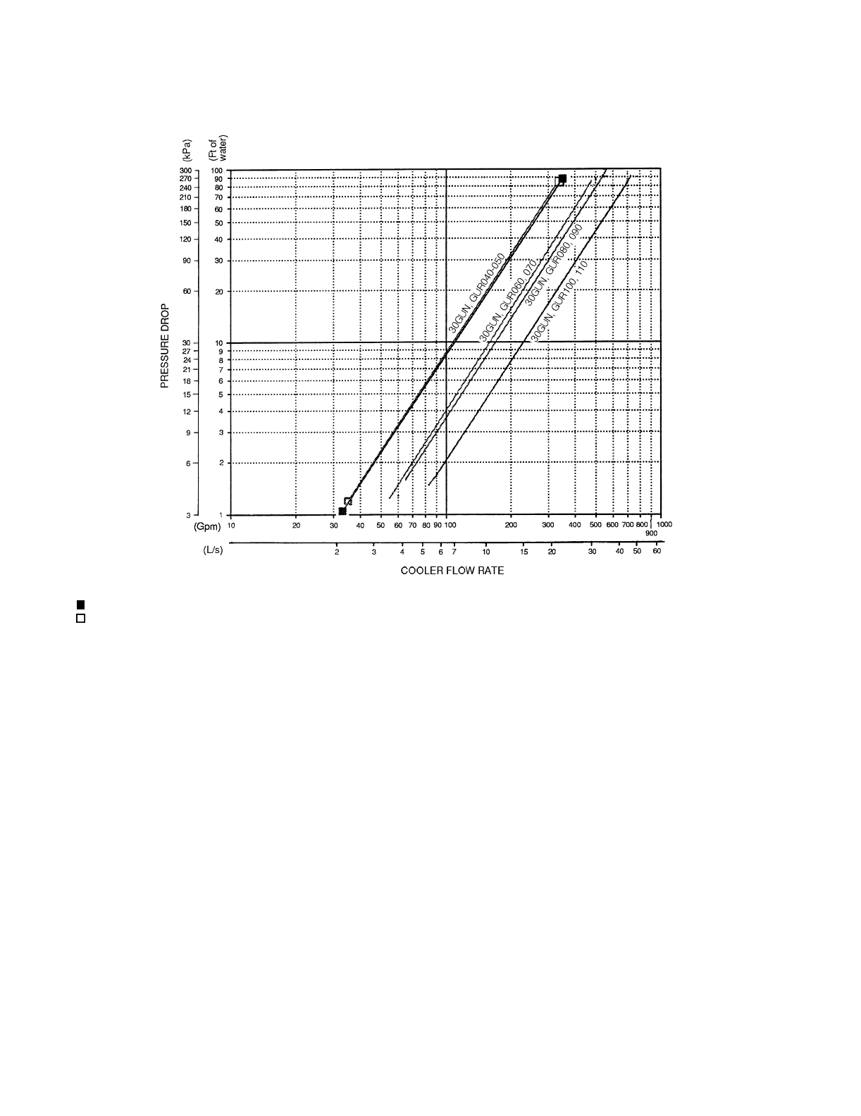
80
APPENDIX B — FLUID DROP PRESSURE CURVES
Cooler Fluid Pressure Drop Curves — 30GUN,GUR040-110
ENGLISH AND SI
LEGEND
NOTE: Ft of water = 2.31 x change in psig.
—040
—045,050
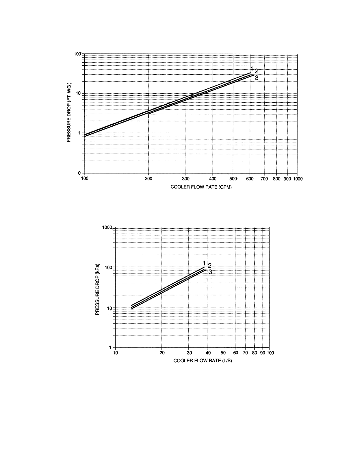
81
APPENDIX B — FLUID DROP PRESSURE CURVES (cont)
Cooler Fluid Pressure Drop Curves — 30GUN,GUR130-210
ENGLISH
SI
COOLER PRESSURE DROP KEY
1 — 30GUN,GUR130,150
2 — 30GUN,GUR170,190
3 — 30GUN,GUR210
NOTE: Ft of water = 2.31 x change in psig.

82
APPENDIX B — FLUID DROP PRESSURE CURVES (cont)
Cooler Fluid Pressure Drop Curves — 30GUN,GUR230A-255A, 270A/B-420A/B
ENGLISH
SI
COOLER PRESSURE DROP KEY
1 Module B — 30GUN,GUR270
2 Module A — 30GUN,GUR230-255
3 Module A — 30GUN,GUR270,330
Module B — 30GUN,GUR330,360 (50 Hz)
4 Module A — 30GUN,GUR290,315,360 (50 or 60 Hz), 390, and 420
Module B — 30GUN,GUR360 (60 Hz), 390, and 420

83
APPENDIX B — FLUID DROP PRESSURE CURVES (cont)
Cooler Fluid Pressure Drop Curves — 30GUN,GUR230B-315B
ENGLISH AND SI
COOLER PRESSURE DROP KEY
1 Module B — 30GUN,GUR230,245
2 Module B — 30GUN,GUR255,290,315
NOTE: Ft of water = 2.31 x change in psig.

84
APPENDIX B — FLUID DROP PRESSURE CURVES (cont)
Cooler Fluid Pressure Drop Curves — 30GTN,GTR040-110
ENGLISH AND SI
LEGEND
NOTE: Ft of water = 2.31 x change in psig.
—040
—045,050
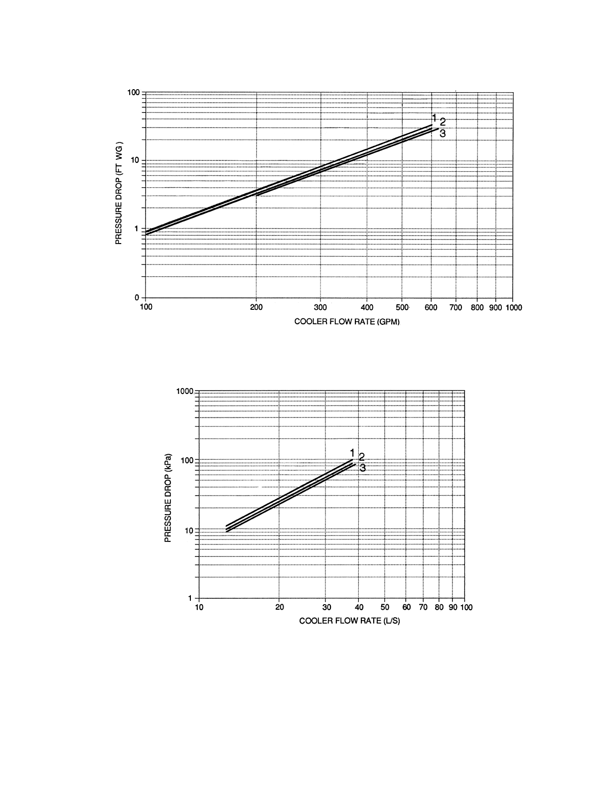
85
APPENDIX B — FLUID DROP PRESSURE CURVES (cont)
Cooler Fluid Pressure Drop Curves — 30GTN,GTR130-210
ENGLISH
SI
COOLER PRESSURE DROP KEY
1 — 30GTN,GTR130,150
2 — 30GTN,GTR170,190
3 — 30GTN,GTR210
NOTE: Ft of water = 2.31 x change in psig.
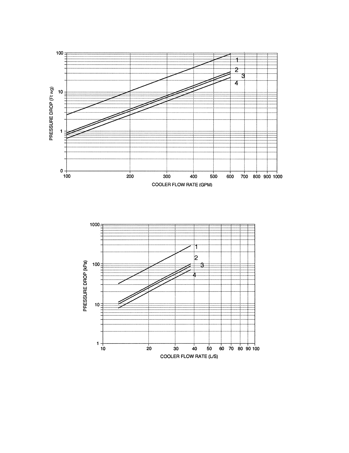
86
APPENDIX B — FLUID DROP PRESSURE CURVES (cont)
Cooler Fluid Pressure Drop Curves — 30GTN,GTR230A-420A, 270B, 330B-420B
ENGLISH
SI
COOLER PRESSURE DROP KEY
1 Module B — 30GTN,GTR270
2 Module A — 30GTN,GTR230-255
3 Module A — 30GTN,GTR270,330
Module B — 30GTN,GTR330,360 (50 Hz)
4 Module A — 30GTN,GTR290,315,360 (50 or 60 Hz), 390, and 420
Module B — 30GTN,GTR360 (60 Hz), 390, and 420
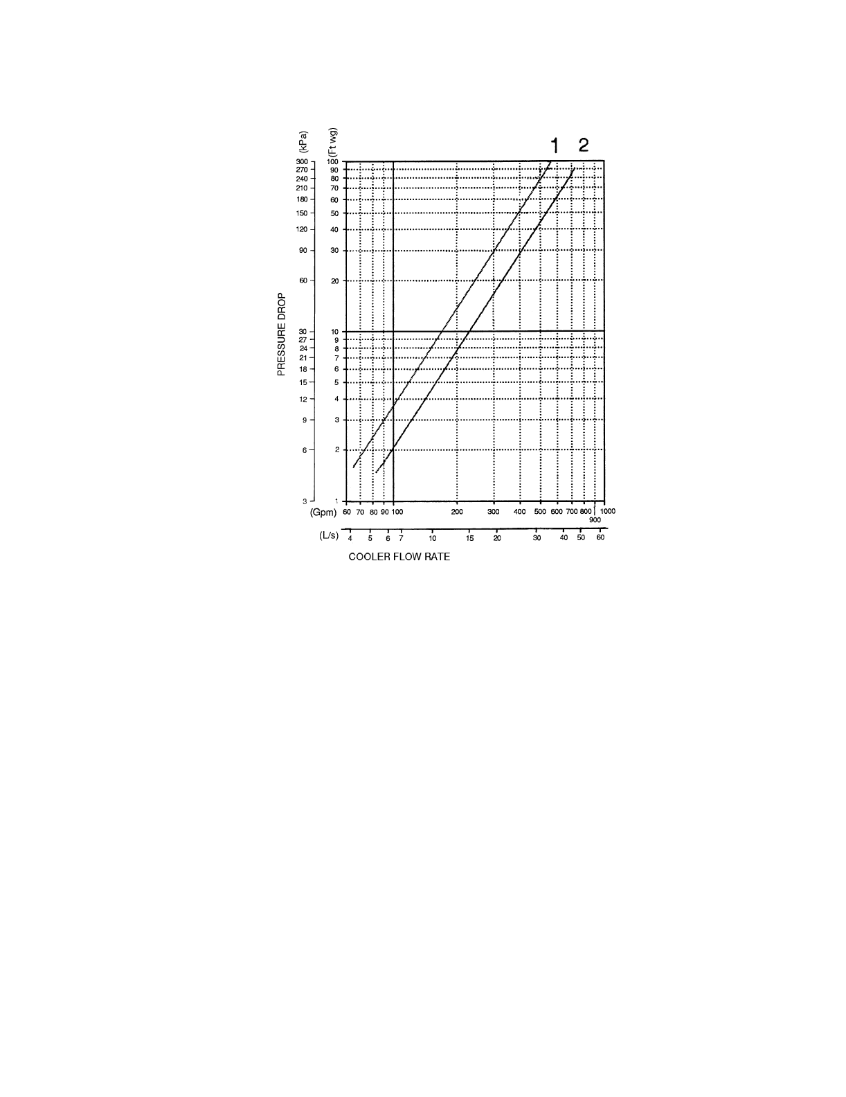
87
APPENDIX B — FLUID DROP PRESSURE CURVES (cont)
Cooler Fluid Pressure Drop Curves — 30GTN,GTR230B, 245B, 255B, 290B, 315B
ENGLISH AND SI
COOLER PRESSURE DROP KEY
1 Module B — 30GTN,GTR230,245
2 Module B — 30GTN,GTR255,290,315
NOTE: Ft of water = 2.31 x change in psig.
Manufacturer reserves the right to discontinue, or change at any time, specifications or designs without notice and without incurring obligations.
PC 903 Catalog No. 563-025 Printed in U.S.A. Form 30GTN-3T Pg 88 3-00 Replaces: 30GTN-2T
Book 2
Ta b 5 c
Copyright 2000 Carrier Corporation
SERVICE TRAINING
Packaged Service Training programs are an excellent way to increase your knowledge of the equipment
discussed in this manual, including:
•Unit Familiarization •Maintenance
•Installation Overview •Operating Sequence
A large selection of product, theory, and skills programs are available, using popular video-based
formats and materials. All include video and/or slides, plus companion book.
Classroom Service Training which includes “hands-on” experience with the products in our labs can
mean increased confidence that really pays dividends in faster troubleshooting and fewer callbacks. Course
descriptions and schedules are in our catalog.
CALL FOR FREE CATALOG 1-800-962-9212
[ ] Packaged Service Training [ ] Classroom Service Training
Manufacturer reserves the right to discontinue, or change at any time, specifications or designs without notice and without incurring obligations.
PC 903 Catalog No. 563-025 Printed in U.S.A. Form 30GTN-3T Pg CL-1 3-00 Replaces: 30GTN-2T
Book 2
Ta b 5 c
CUT ALONG DOTTED LINE CUT ALONG DOTTED LINE
- - - - - - - - - - - - - - - - - - - - - - - - - - - - - - - - - - - - - - - - - - - - - - - - - - - - - - - - - - - - - - - - - - - - - - - - - - - - - - - - - - - - - - - - - - - - - - - - - - - - - - - - - - - - - - - - - - - - - - - - - - - - - - - - - - - - - - - - - - - - - - - - - - - - - - - - - - - - - - - - -
START-UP CHECKLIST FOR COMFORTLINK™ CHILLER SYSTEMS
(Remove and use for job file)
A. Preliminary Information
JOB NAME _______________________________________________________________________________
LOCATION _______________________________________________________________________________
INSTALLING CONTRACTOR _________________________________________________________________
DISTRIBUTOR ____________________________________________________________________________
START-UP PERFORMED BY _________________________________________________________________
EQUIPMENT: Chiller: MODEL NO. SERIAL NO.
COMPRESSORS:
COOLER:
MODEL NO. MANUFACTURED BY
SERIAL NO. DATE
TYPE OF EXPANSION VALVES (check one): EXV TXV
AIR-HANDLING EQUIPMENT:
MANUFACTURER
MODEL NO. SERIAL NO.
ADDITIONAL AIR-HANDLING UNITS AND ACCESSORIES
CIRCUIT A CIRCUIT B
1) MODEL NO. 1) MODEL NO.
SERIAL NO. SERIAL NO.
MTR NO. MTR NO.
2) MODEL NO. 2) MODEL NO.
SERIAL NO. SERIAL NO.
MTR NO. MTR NO.
3) MODEL NO. 3) MODEL NO.
SERIAL NO. SERIAL NO.
MTR NO. MTR NO.
4) MODEL NO.
SERIAL NO.
MTR NO.
CL-2
B. Preliminary Equipment Check
(
Check box if complete
)
IS THERE ANY SHIPPING DAMAGE? IF SO, WHERE
_________________________________________________________________________________________
WILL THIS DAMAGE PREVENT UNIT START-UP?
HAVE COMPRESSOR BASE RAIL ISOLATORS ALL BEEN PROPERLY ADJUSTED?
CHECK POWER SUPPLY. DOES IT AGREE WITH UNIT?
HAS THE CIRCUIT PROTECTION BEEN SIZED AND INSTALLED PROPERLY?
(refer to Installation Instructions)
ARE THE POWER WIRES TO THE UNIT SIZED AND INSTALLED PROPERLY?
(refer to Installation Instructions)
HAS THE GROUND WIRE BEEN CONNECTED?
ARE ALL TERMINALS TIGHT?
CHECK AIR SYSTEMS (Check box if complete)
ALL AIR HANDLERS OPERATING? (refer to air-handling equipment Installation and Start-Up Instructions)
ALL CHILLED FLUID VALVES OPEN?
ALL FLUID PIPING CONNECTED PROPERLY?
ALL AIR BEEN VENTED FROM THE COOLER LOOP?
CHILLED WATER (FLUID) PUMP (CWP) OPERATING WITH THE CORRECT ROTATION?
CWP MOTOR AMPERAGE: Rated Actual
PUMP PRESSURE: Inlet Outlet
C. Unit Start-Up (insert check mark as each item is completed)
CHILLER HAS BEEN PROPERLY INTERLOCKED WITH THE AUXILIARY CONTACTS OF THE CHILLED
FLUID PUMP STARTER.
UNIT IS SUPPLIED WITH CORRECT CONTROL VOLTAGE POWER
(115 V FOR 208/230, 460, AND 575 V UNITS; 230 V FOR 380 AND 380/415 UNITS)
CRANKCASE HEATERS HAVE BEEN ENERGIZED FOR A MINIMUM OF 24 HOURS PRIOR TO START-UP.
COMPRESSOR OIL LEVEL IS CORRECT.
BOTH LIQUID LINE SERVICE VALVES ARE BACKSEATED.
ALL COMPRESSOR DISCHARGE SERVICE VALVES ARE BACKSEATED.
ALL COMPRESSOR SUCTION SERVICE VALVES ARE BACKSEATED.
LOOSEN COMPRESSOR SHIPPING HOLDDOWN BOLTS.
LEAK CHECK THOROUGHLY: CHECK ALL COMPRESSORS, CONDENSER MANIFOLDS AND HEADERS,
EXVs, TXVs, SOLENOID VALVES, FILTER DRIERS, FUSIBLE PLUGS, THERMISTORS, AND COOLER
HEADS, WITH ELECTRONIC LEAK DETECTOR.
LOCATE, REPAIR, AND REPORT ANY REFRIGERANT LEAKS.

CL-3
CUT ALONG DOTTED LINE CUT ALONG DOTTED LINE
- - - - - - - - - - - - - - - - - - - - - - - - - - - - - - - - - - - - - - - - - - - - - - - - - - - - - - - - - - - - - - - - - - - - - - - - - - - - - - - - - - - - - - - - - - - - - - - - - - - - - - - - - - - - - - - - - - - - - - - - - - - - - - - - - - - - - - - - - - - - - - - - - - - - - - - - - - - - - - - - -
C. Unit Start-Up (cont)
CHECK VOLTAGE IMBALANCE: AB AC BC
AB + AC + BC (divided by 3) = AVERAGE VOLTAGE = V
MAXIMUM DEVIATION FROM AVERAGE VOLTAGE =
IF OVER 2% VOLTAGE IMBALANCE, DO NOT ATTEMPT TO START CHILLER!
CALL LOCAL POWER COMPANY FOR ASSISTANCE.
INCOMING POWER VOLTAGE TO CHILLER MODULES IS WITHIN RATED UNIT VOLTAGE
RANGE.
SYSTEM FLUID VOLUME IN LOOP: TYPE SYSTEM:
AIR CONDITIONING — MINIMUM 3 GAL PER NOMINAL TON (3.25 L PER kW) = GAL (L)
PROCESS COOLING — MINIMUM 6 GAL PER NOMINAL TON (6.50 L PER kW) = GAL (L)
CHECK PRESSURE DROP ACROSS COOLER.
FLUID ENTERING COOLER: PSIG (kPa)
FLUID LEAVING COOLER: PSIG (kPa)
(PSIG DIFFERENCE) x 2.31 = FT OF FLUID PRESSURE DROP =
PLOT COOLER PRESSURE DROP ON PERFORMANCE DATA CHART (LOCATED IN PRODUCT DATA
LITERATURE) TO DETERMINE TOTAL GPM (L/s).
TOTAL GPM (L/s) = UNIT’S RATED MIN GPM (L/s) =
GPM (L/s) PER TON = UNIT’S RATED MIN PRESSURE DROP =
(Refer to product data literature.)
JOB’S SPECIFIED GPM (L/s) (if available):
NOTE: IF UNIT HAS LOW FLUID FLOW, FIND SOURCE OF PROBLEM: CHECK FLUID PIPING, IN-LINE
FLUID STRAINER, SHUT-OFF VALVES, CWP ROTATION, ETC.
COOLER LOOP FREEZE PROTECTION IF REQUIRED:
GALLONS (LITERS) ADDED:
PIPING INCLUDES ELECTRIC TAPE HEATERS (Y/N):
VISUALLY CHECK MAIN BASE BOARD AND EXV BOARD FOR THE FOLLOWING:
INSPECT ALL THERMISTORS AND EXV CABLES FOR POSSIBLE CROSSED WIRES.
CHECK TO BE SURE ALL WELL-TYPE THERMISTORS ARE FULLY INSERTED INTO THEIR
RESPECTIVE WELLS.
ALL CABLES AND PIN CONNECTORS TIGHT?
ALL EXV, EMM, AND CXB BOARDS (IF INSTALLED) AND DISPLAY CONNECTIONS TIGHT?
VOLTAGE IMBALANCE = (MAX. DEVIATION) x 100 = % VOLTAGE IMBALANCE
AVERAGE VOLTAGE
CL-4
C. Unit Start-Up (cont)
UNIT (Configuration Settings)
PRESS ESCAPE KEY TO DISPLAY ‘UNIT’. PRESS DOWN ARROW KEY TO DISPLAY ‘OPT1’.
PRESS ENTER KEY. RECORD CONFIGURATION INFORMATION BELOW:
OPTIONS1 (Options Configuration)
ITEM DESCRIPTION STATUS UNITS VALUE
TYPE Unit Type 1 = Air Cooled
2 = Water Cooled
3 = Split System
4 = Heat Machine
5 = Air Cooled Heat Reclaim
TONS Unit Size 15 to 300 TONS
CAP.A Circuit A1% Capacity 0 to 100 %
CMP.A Number Circ A Compressor 1 to 4
CYL.A Compressor A1 Cylinders 4 or 6
CMP.B Number Circ B Compressor 1 to 4
CYL.B Compressor B1 Cylinders 4 or 6
EXV EXV Module Installed No/Yes
SH.SP EXV Superheat Setpoint 10 to 40 ^F
SH.OF EXV Superheat Offset –20 to 20 ^F
REFG Refrigerant 1 = R22 2 = R134A
FAN.S Fan Staging Select 1 = 2 Stage indpt.
2 = 3 Stage indpt.
3 = 2 Stage common
4 = 3 Stage common
ITEM DESCRIPTION STATUS VALUE
FLUD Cooler Fluid 1 = Water
2 = Med. Brine
3 = Low Brine
HGB.S Hot Gas Bypass Select No/Yes
HPCM Head Press. Cont. Method 1 = EXV controlled
2 = Setpoint controlled
3 = Setpoint-A, EXV-B
4 = EXV-A, Setpoint-B
HPCT Head Press. Control Type 0 = None
1 = Air Cooled
2 = Water Cooled
MMR.S Motormaster Select No/Yes
PRTS Pressure Transducer No/Yes
PMP.I Cooler Pump Interlock Off/On
CPC Cooler Pump Control Off/On
CNP.I Condenser Pump Interlock Off/On
CNPC Condenser Pump Control 0 = No Control
1 = On with Mode
2 = On with Compressor(s)
CWT.S Condenser Fluid Sensors No/Yes
CA.UN No. Circuit A Unloaders 0-2
CB.UN No. Circuit B Unloaders 0-2
EMM EMM Module Installed No/Yes
CL-5
CUT ALONG DOTTED LINE CUT ALONG DOTTED LINE
- - - - - - - - - - - - - - - - - - - - - - - - - - - - - - - - - - - - - - - - - - - - - - - - - - - - - - - - - - - - - - - - - - - - - - - - - - - - - - - - - - - - - - - - - - - - - - - - - - - - - - - - - - - - - - - - - - - - - - - - - - - - - - - - - - - - - - - - - - - - - - - - - - - - - - - - - - - - - - - - -
C. Unit Start-Up (cont)
PRESS ESCAPE KEY TO DISPLAY ‘OPT1’. PRESS DOWN ARROW KEY TO DISPLAY ‘OPT2’.
PRESS ENTER KEY.
RECORD CONFIGURATION INFORMATION BELOW:
OPTIONS2 (Options Configuration)
PRESS ESCAPE KEY TO DISPLAY ‘OPT2’. PRESS DOWN ARROW KEY TO DISPLAY ‘RSET’.
PRESS ENTER KEY.
RECORD CONFIGURATION INFORMATION BELOW:
RESETCON (Temperature Reset and Demand Limit)
ITEM DESCRIPTION STATUS UNITS VALUE
CTRL Control Method 0 = Switch
1 = 7 day sched.
2 = Occupancy
3 = CCN
CCNA CCN Address 1 to 239
CCNB CCN Bus Number 0 to 239
BAUD CCN Baud Rate 1 = 240
2 = 480
3 = 9600
4 = 19,200
5 = 38,400
LOAD Loading Sequence Select 1 = Equal loading
2 = Staged loading
LLCS Lead/Lag Circuit Select 1 = Automatic
2 = Circuit A leads
3 = Circuit B leads
LCWT High LCW Alert Limit 2 to 60 ^F
DELY Minutes off time 0 to 15 min.
ICE.M Ice Mode Enable Enable/Disable
ITEM DESCRIPTION STATUS UNITS VALUE
COOLING RESET
CRST Cooling Reset Type 0 = No Reset
1 = 4-20 mA input
2 = External temp-OAT
3 = Return fluid
4 = External temp-SPT
CRT1 No Cool Reset Temp 0 to 125 °F
CRT2 Full Cool Reset Temp 0 to 125 °F
DGRC Degrees Cool Reset –30 to 30 ^F
HRST Heating Reset Type 0 = No Reset
1 = 4-20 mA input
2 = External temp-OAT
3 = Return fluid
4 = External temp-SPT
HRT1 No Heat Reset Temp Not Supported °F
HRT2 Full Heat Reset Temp Not Supported °F
DGRH Degrees Heat Reset –30 to 30 ^F
DEMAND LIMIT
DMDC Demand Limit Select 0 = None
1 = External switch input
2 = 4-20 ma input
3 = Loadshed
0
DM20 Demand Limit at 20mA 0 to 100 %
SHNM Loadshed Group Number 0 to 99
SHDL Loadshed Demand Delta 0 to 60 %
SHTM Maximum Loadshed Time 0 to 120 min
DLS1 Demand Limit Switch 1 0 to 100 %
DLS2 Demand Limit Switch 2 0 to 100 %
LEAD/LAG
LLEN Lead/Lag Chiller Enable Enable/Disable
MSSL Master/Slave Select Slave/Master
SLVA Slave Address 0 to 239
LLBL Lead/Lag Balance Select Enable/Disable
LLBD Lead/Lag Balance Delta 40 to 400 hours
LLDY Lag Start Delay 0 to 30 min
CL-6
C. Unit Start-Up (cont)
PRESS ESCAPE KEY TO DISPLAY ‘RSET’. PRESS DOWN ARROW KEY TO DISPLAY ‘SLCT’.
PRESS ENTER KEY.
RECORD CONFIGURATION INFORMATION BELOW:
SLCT (Heating Cooling Setpoint Select)
PRESS ESCAPE KEY SEVERAL TIMES TO GET TO THE MODE LEVEL (BLANK DISPLAY). USE THE
ARROW KEYS TO SCROLL TO THE SET POINT LED. PRESS ENTER TO DISPLAY SETPOINTS.
RECORD CONFIGURATION INFORMATION BELOW:
SETPOINT
USE ARROW/ESCAPE KEYS TO ILLUMINATE TEMPERATURES LED. PRESS ENTER TO DISPLAY
‘UNIT’. PRESS ENTER AND USE THE ARROW KEYS TO RECORD TEMPERATURES FOR T1 AND
T2 BELOW. RECORD T9 AND T10 IF INSTALLED. RECORD CONDENSER ENTERING AND LEAVING
FLUID TEMPERATURES IF INSTALLED. PRESS ESCAPE TO DISPLAY ‘UNIT’ AGAIN AND PRESS
THE DOWN ARROW KEY TO DISPLAY ‘CIR.A’. PRESS ENTER AND USE THE ARROW KEYS
TO RECORD TEMPERATURE FOR T3 (30GTN,R ONLY). USING A DC VOLTMETER, MEASURE
AND RECORD THE VOLTAGE FOR EACH THERMISTOR AT THE LOCATION SHOWN. FOR MODELS
WITH QUICKSET, RECORD THE TEMPERATURES ACCORDING TO THE DC VOLTAGES USING
TABLES 32A-33B.
ITEM DESCRIPTION STATUS UNITS VALUE
CLSP Cooling Setpoint Select 0 = Single
1 = Dual Switch
2 = Dual Clock
3 = 4 to 20 mA Input
4 = 4-20 mA Input
5 = External Setpoint Potentiometer
HTSP Heating Setpoint Select 0 = Single
1 = Dual Switch
2 = Dual 7 day schedule
3 = Dual CCN occupancy
4 = 4-20 mA Input
5 = Setpoint Potentiometer
RL.S Ramp Load Select Enable/Disable
CRMP Cooling Ramp Loading 0.2 to 2.0
HRMP Heating Ramp Loading 0.2 to 2.0
HCSW Heat Cool Select Cool/Heat
Z.GN Deadband Multiplier 1.0 to 4.0
SUB-MODE ITEM DESCRIPTION STATUS UNITS VALUE
COOL CSP.1 Cooling Setpoint 1 –20 to 70 °F
CSP.2 Cooling Setpoint 2 –20 to 70 °F
CSP.3 Cooling Setpoint 3 –20 to 32 °F
HEAT HSP.1 Heating Setpoint 1 80 to 140 °F
HSP.2 Heating Setpoint 2 80 to 140 °F
HEAD HD.P.A Head Pressure Setpoint A 80 to 140 °F
HD.P.B Head Pressure Setpoint B 80 to 140 °F
TEMPERATURE VDC BOARD LOCATION
T1 (CLWT) MBB, J8 PINS 13,14
T2 (CEWT) MBB, J8 PINS 11,12
T3 (SCT.A) MBB, J8 PINS 21,22
T9 (OAT) MBB, J8 PINS 7,8
T10 (SPT) MBB, J8 PINS 5,6
(CNDE) MBB, J8 PINS 1,2
(CNDL) MBB, J8 PINS 3,4

CL-7
CUT ALONG DOTTED LINE CUT ALONG DOTTED LINE
- - - - - - - - - - - - - - - - - - - - - - - - - - - - - - - - - - - - - - - - - - - - - - - - - - - - - - - - - - - - - - - - - - - - - - - - - - - - - - - - - - - - - - - - - - - - - - - - - - - - - - - - - - - - - - - - - - - - - - - - - - - - - - - - - - - - - - - - - - - - - - - - - - - - - - - - - - - - - - - - -
C. Unit Start-Up (cont)
USE ESCAPE/ARROW KEYS TO ILLUMINATE CONFIGURATION LED. PRESS ENTER TO DISPLAY ‘DISP’.
PRESS ENTER AGAIN TO DISPLAY ‘TEST’ FOLLOWED BY ‘OFF’. PRESS ENTER TO STOP DISPLAY AT
‘OFF’ AND ENTER AGAIN SO ‘OFF’ DISPLAY FLASHES. ‘PA S S ’ AND ‘WORD’ WILL FLASH IF PASSWORD
NEEDS TO BE ENTERED. PRESS ENTER TO DISPLAY PASSWORD FIELD AND USE THE ENTER KEY FOR
EACH OF THE FOUR PASSWORD DIGITS. USE ARROW KEYS IF PASSWORD IS OTHER THAN STANDARD.
AT FLASHING ‘OFF’ DISPLAY, PRESS THE UP ARROW KEY TO DISPLAY ’ON’ AND PRESS ENTER. ALL LED
SEGMENTS AND MODE LEDS WILL LIGHT UP. PRESS ESCAPE TO STOP THE TEST. PRESS ESCAPE TO
RETURN TO THE ‘DISP’ DISPLAY. PRESS THE ESCAPE KEY AGAIN AND USE THE ARROW KEYS TO ILLU-
MINATE THE SERVICE TEST LED. PRESS ENTER TO DISPLAY ‘TEST’. PRESS ENTER TO STOP DISPLAY
AT ‘OFF’ AND ENTER AGAIN SO ‘OFF’ FLASHES. PRESS THE UP ARROW KEY AND ENTER TO ENABLE
THE MANUAL MODE. PRESS ESCAPE AND DISPLAY NOW SAYS ‘TEST’ ‘ON’.
PRESS THE DOWN ARROW TO DISPLAY ‘OUTS’. PRESS THE ENTER KEY TO DISPLAY ‘LLS.A’. PRESS
THE ENTER KEY TO STOP DISPLAY AT ‘OFF’ AND ENTER AGAIN SO ‘OFF’ FLASHES. PRESS THE UP
ARROW KEY AND ENTER TO TURN THE OUTPUT ON. PRESS ENTER SO THE ‘ON’ DISPLAY FLASHES,
PRESS THE DOWN ARROW KEY AND THEN ENTER TO TURN THE OUTPUT OFF. OUTPUTS WILL ALSO BE
TURNED OFF OR SENT TO 0% WHEN ANOTHER OUTPUT IS TURNED ON. CHECK OFF THE FOLLOWING
THAT APPLY AFTER BEING TESTED:
USE ESCAPE KEY TO RETURN TO ‘OUTS’ DISPLAY. PRESS DOWN ARROW TO DISPLAY ‘COMP’. PRESS
ENTER KEY TO DISPLAY ‘CC.A1’. NOTE THAT UNLOADERS AND HOT GAS BYPASS SOLENOIDS CAN BE
TESTED BOTH WITH AND WITHOUT COMPRESSOR(S) RUNNING. MAKE SURE ALL SERVICE VALVES ARE
OPEN AND COOLER/CONDENSER PUMPS HAVE BEEN TURNED ON BEFORE STARTING COMPRES-
SORS. CHECK OFF EACH ITEM AFTER SUCCESSFUL TEST. THE CONTROL WILL ONLY START ONE COM-
PRESSOR PER MINUTE. WHEN AT THE DESIRED ITEM, PRESS THE ENTER KEY TWICE TO MAKE THE
‘OFF’ FLASH. PRESS THE UP ARROW KEY AND ENTER TO TURN THE OUTPUT ON.
CHECK AND ADJUST SUPERHEAT AS REQUIRED.
LLS.A N/A EXV.A
LLS.B N/A EXV.B
FAN1 FAN2
FAN3 FAN4
CLR.P (TB5 — 10,12) CND.P N/A
RMT.A (TB5 — 11,12)
CC.A1 CC.A2
CC.A3 CC.A4
UL.A1 UL.A2
HGBP
CC.B1 CC.B2
CC.B3 CC.B4
UL.B1 UL.B2

Manufacturer reserves the right to discontinue, or change at any time, specifications or designs without notice and without incurring obligations.
PC 903 Catalog No. 563-025 Printed in U.S.A. Form 30GTN-3T Pg CL-8 3-00 Replaces: 30GTN-2T
Book 2
Ta b 5 c
Copyright 2000 Carrier Corporation
All Units:
MEASURE THE FOLLOWING (MEASURE WHILE MACHINE IS IN STABLE OPERATING CONDITION):
CIRCUIT A CIRCUIT B
DISCHARGE PRESSURE
SUCTION PRESSURE
OIL PRESSURE
DISCHARGE LINE TEMP
SUCTION LINE TEMP
SATURATED COND TEMP (T3/T4)
SATURATED SUCT TEMP (T5/T6)
SUCTION GAS TEMP (T7/T8)
COOLER ENT FLUID (T2)
COOLER LVG FLUID (T1)
