Carrier Aquaforce 30Xa080 500 Users Manual 30xa 10si Rev A
30xa0805001 01d93514-32de-4609-a931-af103e1cd66e Carrier Fan 30XA080-500 User Guide |
2015-01-24
: Carrier Carrier-Aquaforce-30Xa080-500-Users-Manual-310702 carrier-aquaforce-30xa080-500-users-manual-310702 carrier pdf
Open the PDF directly: View PDF ![]() .
.
Page Count: 80
Manufacturer reserves the right to discontinue, or change at any time, specifications or designs without notice and without incurring obligations.
Catalog No. 04-53300026-01 Printed in U.S.A. Form 30XA-10SI Pg 1 11-09 Replaces: 30XA-5SI
Installation Instructions
CONTENTS
Page
SAFETY CONSIDERATIONS . . . . . . . . . . . . . . . . . . . . . . 1
INTRODUCTION . . . . . . . . . . . . . . . . . . . . . . . . . . . . . . . . . . 1
INSTALLATION . . . . . . . . . . . . . . . . . . . . . . . . . . . . . . . . 1-78
Storage . . . . . . . . . . . . . . . . . . . . . . . . . . . . . . . . . . . . . . . . . . 1
Step 1 — Inspect Shipment . . . . . . . . . . . . . . . . . . . . . . 1
Step 2 — Place, Mount and Rig Unit. . . . . . . . . . . . . 2
•PLACING UNIT
• MOUNTING UNIT
• RIGGING UNIT
Step 3 — Cooler Fluid and Drain Piping
Connections . . . . . . . . . . . . . . . . . . . . . . . . . . . . . . . . . . 41
• GENERAL
• UNITS WITH A HYDRONIC PUMP PACKAGE
• UNITS WITHOUT A HYDRONIC PUMP PACKAGE
• DUAL CHILLER CONTROL
• COOLER PUMP CONTROL
• BRINE UNITS
• PREPARATION FOR YEAR-ROUND OPERATION
Step 4 — Fill the Chilled Water Loop . . . . . . . . . . . . 56
• WATER SYSTEM CLEANING
• WATER TREATMENT
• SYSTEM PRESSURIZATION
• FILLING THE SYSTEM
• SET WATER FLOW RATE
• PUMP MODIFICATION/TRIMMING
• FREEZE PROTECTION
• PREPARATION FOR WINTER SHUTDOWN
Step 5 — Make Electrical Connections . . . . . . . . . . 62
• POWER SUPPLY
• FIELD POWER CONNECTIONS
•POWER WIRING
• FIELD CONTROL POWER CONNECTIONS
• CARRIER COMFORT NETWORK®
COMMUNICATION BUS WIRING
• NON-CCN COMMUNICATION WIRING
• FIELD CONTROL OPTION WIRING
• DUAL CHILLER LEAVING WATER SENSOR
Step 6 — Install Accessories . . . . . . . . . . . . . . . . . . . . 77
• ENERGY MANAGEMENT MODULE
• REMOTE ENHANCED DISPLAY
• LOW AMBIENT TEMPERATURE OPERATION
• MINIMUM LOAD ACCESSORY
• UNIT SECURITY/PROTECTION ACCESSORIES
• COMMUNICATION ACCESSORIES
• SERVICE OPTIONS
• CONTROL TRANSFORMER
Step 7 — Leak Test Unit . . . . . . . . . . . . . . . . . . . . . . . . . 77
Step 8 — Refrigerant Charging. . . . . . . . . . . . . . . . . . 77
• DEHYDRATION
• REFRIGERANT CHARGE
SAFETY CONSIDERATIONS
Installing, starting up, and servicing this equipment can be
hazardous due to system pressures, electrical components, and
equipment location. Only trained, qualified installers and service
mechanics should install, start up, and service this equipment.
When working on the equipment, observe precautions in the
literature, and on tags, stickers, and labels attached to the
equipment.
• Follow all safety codes.
• Wear safety glasses and work gloves.
• Use care in handling, rigging, and setting bulky equipment.
INTRODUCTION
These instructions cover installation of 30XA080-500 air-
cooled liquid chillers with electronic controls and units with
factory-installed options (FIOPs). See Fig. 1.
INSTALLATION
Storage — If the unit is to be stored for a period of time be-
fore installation or start-up, be sure to protect the machine
from construction dirt. Keep protective shipping covers in
place until the machine is ready for installation.
Step 1 — Inspect Shipment — Inspect unit for dam-
age upon arrival. If damage is found, immediately file a claim
with the shipping company, and contact your local Carrier
representative.
WARNING
Electrical shock can cause personal injury and death. Shut
off all power to this equipment during installation. There
may be more than one disconnect switch. Tag all discon-
nect locations to alert others not to restore power until work
is completed.
IMPORTANT: This equipment generates, uses, and
can radiate radio frequency energy and if not installed
and used in accordance with these instructions may
cause radio interference. It has been tested and found
to comply with the limits of a Class A computing
device as defined by FCC (Federal Communications
Commission, U.S.A.) regulations, Subpart J of Part 15,
which are designed to provide reasonable protection
against such interference when operated in a commer-
cial environment.
AQUAFORCE®
30XA080-500
Air-Cooled Liquid Chillers
2
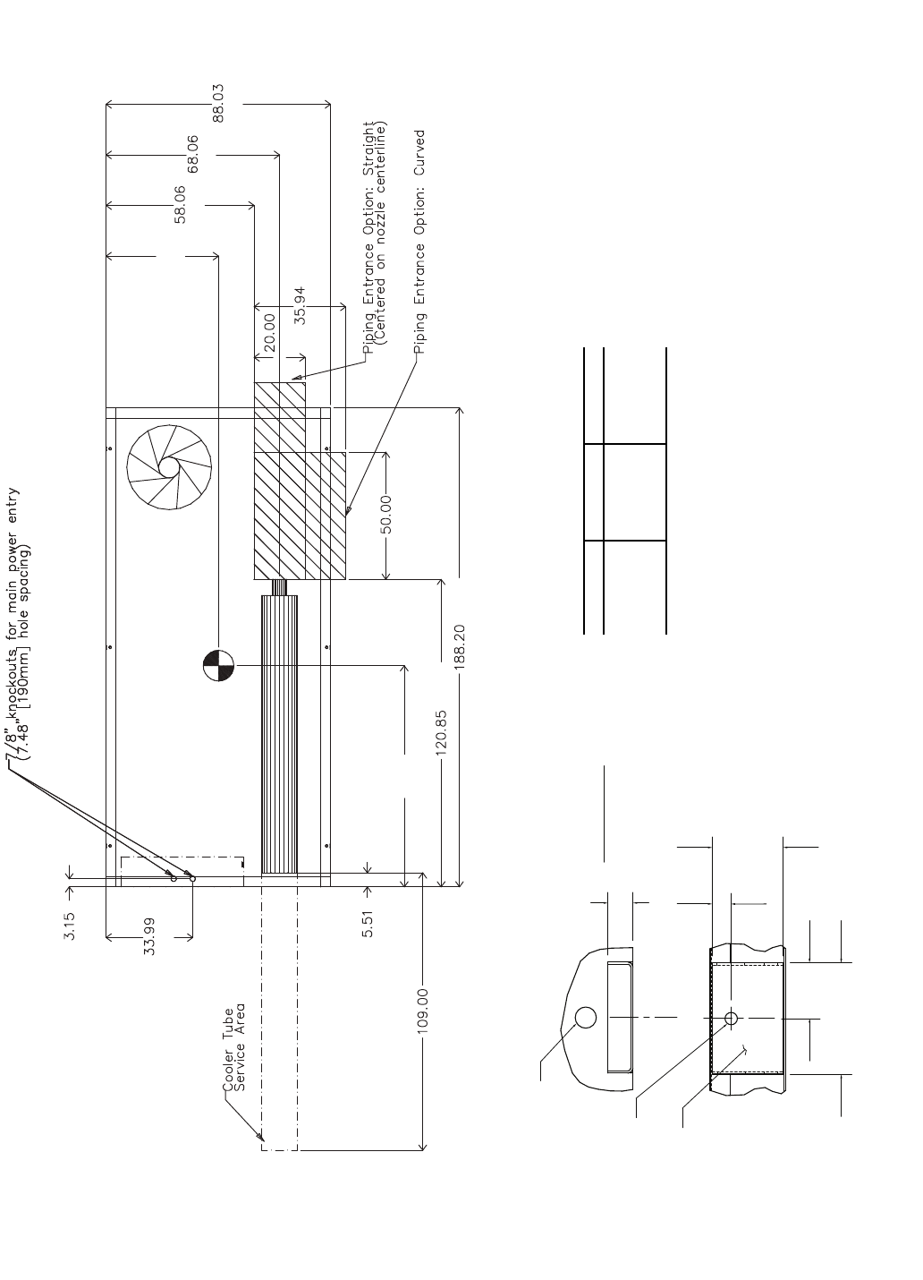
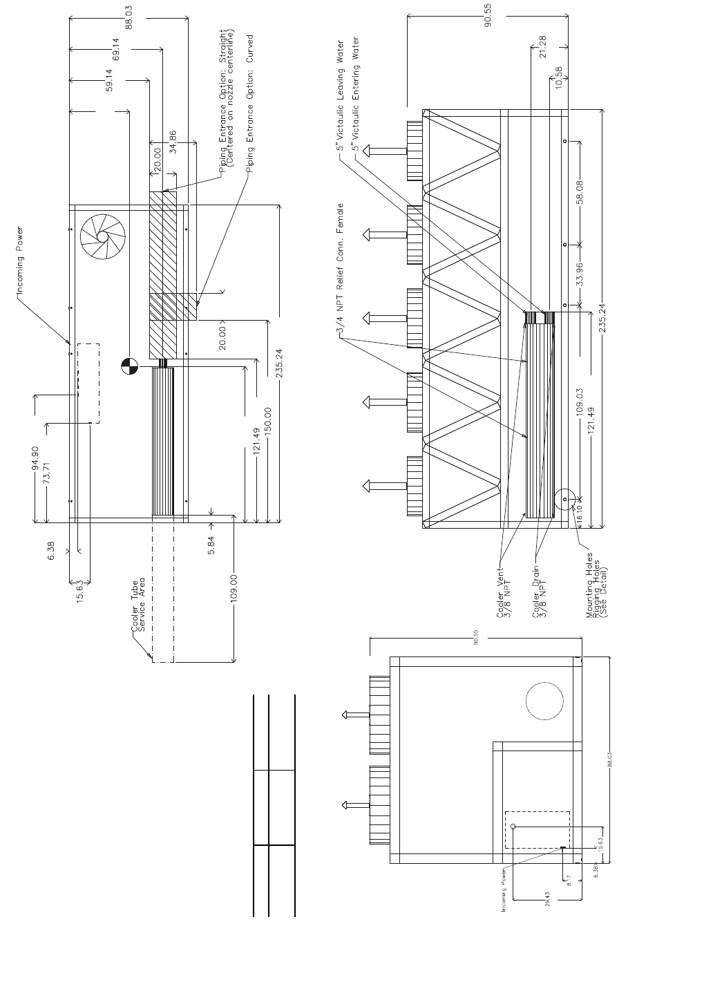
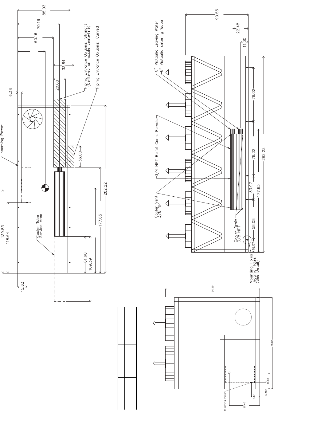
Step 2 — Place, Mount, and Rig the Unit —
When considering a location for the unit, be sure to consult
NEC (National Electrical Code, U.S.A.) and/or local code
requirements. Allow sufficient space for airflow, wiring, pip-
ing, and service. See Fig. 2-14.
NOTE: To facilitate refrigerant vent piping, all units have fus-
ible plugs with 1/4 in. SAE (Society of Automotive Engineers)
flares and pressure reliefs with 3/4 in. NPT fittings (if required
by local codes).
PLACING UNIT — Locate the unit so that the condenser
airflow is unrestricted both above and on the sides of the unit.
Airflow and service clearances are 6 ft (1.8 m) around the unit.
Acceptable clearance on the sides or ends without control boxes
can be reduced to 3 ft (1 m) without sacrificing performance as
long as the remaining three sides are unrestricted. Acceptable
clearance on the side with a control box can be reduced to 4 ft
(1.3 m) due to NEC regulations, without sacrificing performance
as long as the remaining three sides are unrestricted. Provide am-
ple room for servicing and removing the cooler. See Fig. 2-14 for
required clearances. Local codes for clearances take precedence
over the manufacturer’s recommendations when local codes call
for greater clearances.
If multiple units are installed at the same site, a separation of
10 ft (3 m) between the sides of the machines is required to
maintain proper airflow and minimize the chances of condens-
er air recirculation.
MOUNTING UNIT — The unit may be mounted on a level
pad directly on the base rails, on a raised mounting rail around
the unit, or on vibration isolation springs. For all units, ensure
placement area is strong enough to support unit operating
weight. See Tables 1A and 1B. Mounting holes are provided
for securing the unit to the pad, mounting rail or vibration
isolation springs. Bolt the unit securely to pad or rails. If vibra-
tion isolators (field-supplied) are required for a particular
installation, refer to unit weight distribution in Fig. 15A-15C to
aid in the proper selection of isolators. The 30XA units can be
mounted directly on spring isolators. Once installed, the unit
must be level to within 1/8-in. per ft (1 cm per meter) along the
long axis of the oil separator. This is required for oil return to
the compressor(s).
3
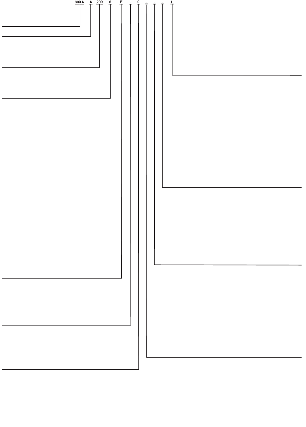
Fig. 1 — AquaForce® Chiller Model Number Designation
a30-4401
LEGEND
CFSP — Coil Face Shipping Protection
EMM — Energy Management Module
LON — Local Operating Network
MCHX — Microchannel Heat Exchanger
XL — Across-the-Line Starter
30XA – AquaForce® Air-Cooled Chiller
Design Series
Unit Sizes
080 140 240 350
090 160 260 400
100 180 280 450
110 200 300 500
120 220 325
Voltage
1 – 575-3-60
2 – 380-3-60
4 – 230-3-60
6 – 460-3-60
7 – 200-3-60
Condenser Coil/Ambient/Low Sound Options
- – Aluminum Fin/Copper Tube, High Ambient Temperature
0 – Copper Fin/Copper Tube, High Ambient Temperature
1 – Aluminum Pre-Coat Fin/Copper Tube, High Ambient Temperature
2 – Aluminum E-Coat Fin/Copper Tube, High Ambient Temperature
3 – Copper E-Coat Fin/Copper Tube, High Ambient Temperature
4 – Novation® Heat Exchanger (MCHX), High Ambient
Temperature
5 – MCHX E-Coat, High Ambient Temperature
6 – Aluminum Fin/Copper Tube, High Ambient Temperature,
Low Sound
7 – Copper Fin/Copper Tube, High Ambient Temperature, Low Sound
8 – Aluminum Pre-Coat Fin/Copper Tube, High Ambient Temperature,
Low Sound
9 – Aluminum E-Coat Fin/Copper Tube, High Ambient Temperature,
Low Sound
B – Copper E-Coat Fin/Copper Tube, High Ambient Temperature,
Low Sound
C – MCHX, High Ambient Temperature, Low Sound
D – MCHX E-Coat, High Ambient Temperature, Low Sound
F – Aluminum Fin/Copper Tube, Standard Ambient Temperature,
Low Sound
G – Copper Fin/Copper Tube, Standard Ambient Temperature,
Low Sound
H – Aluminum Pre-Coat Fin/Copper Tube, Standard Ambient
Temperature, Low Sound
J – Aluminum E-Coated Fin/Copper Tube, Standard Ambient
Temperature, Low Sound
K – Copper E-Coat Fin/Copper Tube, Standard Ambient Temperature,
Low Sound
L – MCHX, Standard Ambient Temperature, Low Sound
M – MCHX E-Coat, Standard Ambient Temperature, Low Sound
N – Aluminum Fin/Copper Tube, Standard Ambient Temperature
P – Copper Fin/Copper Tube, Standard Ambient Temperature
Q – Aluminum Pre-Coat Fin/Copper Tube, Standard Ambient
Temperature
R – Aluminum E-Coat Fin/Copper Tube, Standard Ambient
Temperature
S – Copper E-Coat Fin/Copper Tube, Standard Ambient Temperature
T – MCHX, Standard Ambient Temperature
V – MCHX E-Coat, Standard Ambient Temperature
Cooler/Brine Options
0 – Integral Cooler with Heater
3 – Integral Cooler with Heater, Minus One Pass
5 – Integral Cooler with Heater, Plus One Pass
7 – Integral Cooler with Heater, Full End Screen
H – Integral Cooler with Heater, Plus One Pass, Brine
K – Integral Cooler with Heater, Minus One Pass, Full End Screen
M – Integral Cooler with Heater, Plus One Pass, Full End Screen
V – Integral Cooler with Heater, Plus One Pass, Brine, Full End Screen
Packaging/Security Options
0 – Coil Face Shipping Protection (CFSP), Skid
1 – CFSP, Skid, Top Crate, Bag
3 – CFSP, Coil Trim Panels
4 – CFSP, Skid, Coil Trim Panels
5 – CFSP, Skid, Top Crate, Bag, Coil Trim Panels
7 – CFSP, Coil Trim Panels, Upper and Lower Grilles
8 – CFSP, Skid, Coil Trim Panels, Upper and Lower Grilles
9 – CFSP, Skid, Top Crate, Bag, Coil Trim Panels, Upper and Lower Grilles
C – CFSP, Trim Panels, Upper and Lower Grilles, Upper Hail Guards
D – CFSP, Skid, Coil Trim Panels, Upper and Lower Grilles, Upper Hail Guards
F – CFSP, Skid, Top Crate, Bag, Trim Panels, Upper and Lower Grilles,
Upper Hail Guards
L – CFSP
Controls/Communication Options
- – Navigator™ Display
0 – Navigator Display, EMM
1 – Navigator Display, Service Option
2 – Navigator Display, EMM, Service Option
3 – Touch Pilot™ Display
4 – Touch Pilot Display, EMM
5 – Touch Pilot Display, Service Option
6 – Touch Pilot Display, EMM, Service Option
7 – Navigator Display, BACnet Translator
8 – Navigator Display, BACnet Translator, EMM
9 – Navigator Display, BACnet Translator, Service Option
B – Navigator Display, BACnet Translator, EMM, Service Option
C – Touch Pilot Display, BACnet Translator
D – Touch Pilot Display, BACnet Translator, EMM
F – Touch Pilot Display, BACnet Translator, Service Option
G – Touch Pilot Display, BACnet Translator, EMM, Service Option
H – Navigator Display, LON Translator
J – Navigator Display, LON Translator, EMM
K – Navigator Display, LON Translator, Service Option
L – Navigator Display, LON Translator, EMM, Service Option
M – Touch Pilot Display, LON Translator
N – Touch Pilot Display, LON Translator, EMM
P – Touch Pilot Display, LON Translator, Service Option
Q – Touch Pilot Display, LON Translator, EMM, Service Option
Electrical Options
- – Single Point Power, XL, Terminal Block, No Control Transformer
0 –
Single Point Power, Wye-Delta, Terminal Block, No Control Transformer
3 – Dual Point Power, XL, Terminal Block, No Control Transformer
4 – Dual Point Power, Wye-Delta, Terminal Block, No Control Transformer
7 – Single Point Power, XL, Disconnect, No Control Transformer
8 – Single Point Power, Wye-Delta, Disconnect, No Control Transformer
C – Dual Point Power, XL, Disconnect, No Control Transformer
D – Dual Point Power, Wye-Delta, Disconnect, No Control Transformer
H – Single Point Power, XL, Terminal Block, Control Transformer
J – Single Point Power, Wye-Delta, Terminal Block, Control Transformer
M – Dual Point Power, XL, Terminal Block, Control Transformer
N – Dual Point Power, Wye-Delta, Terminal Block, Control Transformer
R – Single Point Power, XL, Disconnect, Control Transformer
S – Single Point Power, Wye-Delta, Disconnect, Control Transformer
W – Dual Point Power, XL, Disconnect, Control Transformer
X – Dual Point Power, Wye-Delta, Disconnect, Control Transformer
Refrigeration Circuit Options
- – None
0 – Suction Line Insulation
1 – Suction Service Valves
2 – Low Ambient Temperature Head Pressure Control
3 – Suction Line Insulation, Suction Service Valves
4 – Suction Line Insulation, Low Ambient Temperature Head Pressure Control
5 – Suction Service Valves, Low Ambient Temperature Head Pressure Control
6 – Suction Line Insulation, Suction Service Valves, Low Ambient Temperature
Head Pressure Control
7 – Minimum Load Control
8 – Suction Line Insulation, Minimum Load Control
9 – Suction Service Valves, Minimum Load Control
B – Low Ambient Temperature Head Pressure Control, Minimum Load Control
C – Suction Line Insulation, Suction Service Valves, Minimum Load Control
D – Suction Line Insulation, Low Ambient Temperature Head Pressure
Control, Minimum Load Control
F – Suction Service Valves, Low Ambient Temperature Head Pressure
Control, Minimum Load Control
G – Suction Line Insulation, Suction Service Valves, Low Ambient Temperature
Head Pressure Control, Minimum Load Control
Hydronic Pump Package Options
- – None
1 – Single Pump, 5 HP
2 – Single Pump, 7.5 HP
3 – Single Pump, 10 HP
4 – Single Pump, 15 HP
7 – Dual Pump, 5 HP
8 – Dual Pump, 7.5 HP
B – Dual Pump, 10 HP
C – Dual Pump, 15 HP
Quality Assurance
Certified to ISO 9001:2000
4
3.93
7.88
[200]
DETAIL "A"
MOUNTING PLATE
CONTACT SURFACE
TYPICAL 4 PLACES
[100]
MOUNTING HOLE
0.875 DIA.[22.2]
MOUNTING
PLATE
1.50 DIA. [38.1]
RIGGING HOLE
[127]
5.0
[33]
1.31
1.75
[44]
[1114]
[1729]
[2236]
[508]
[1670]
[3587]
[3078]
[148]
[2769]
[80]
[863]
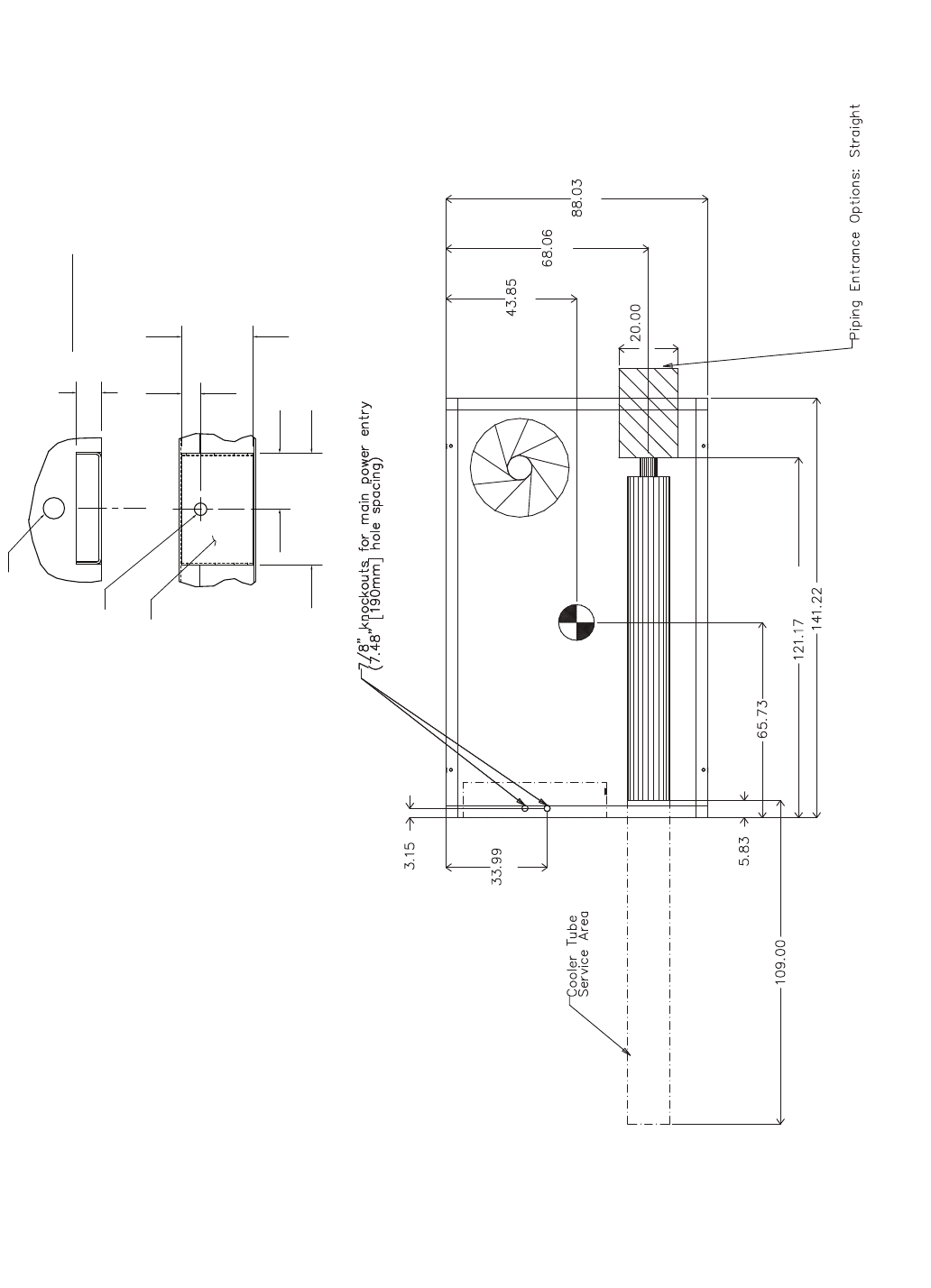
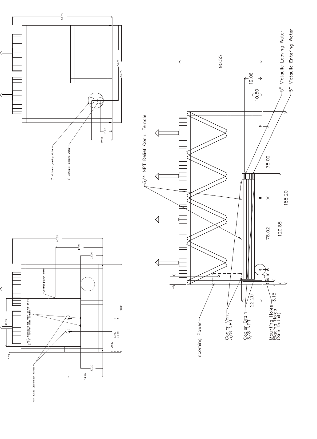
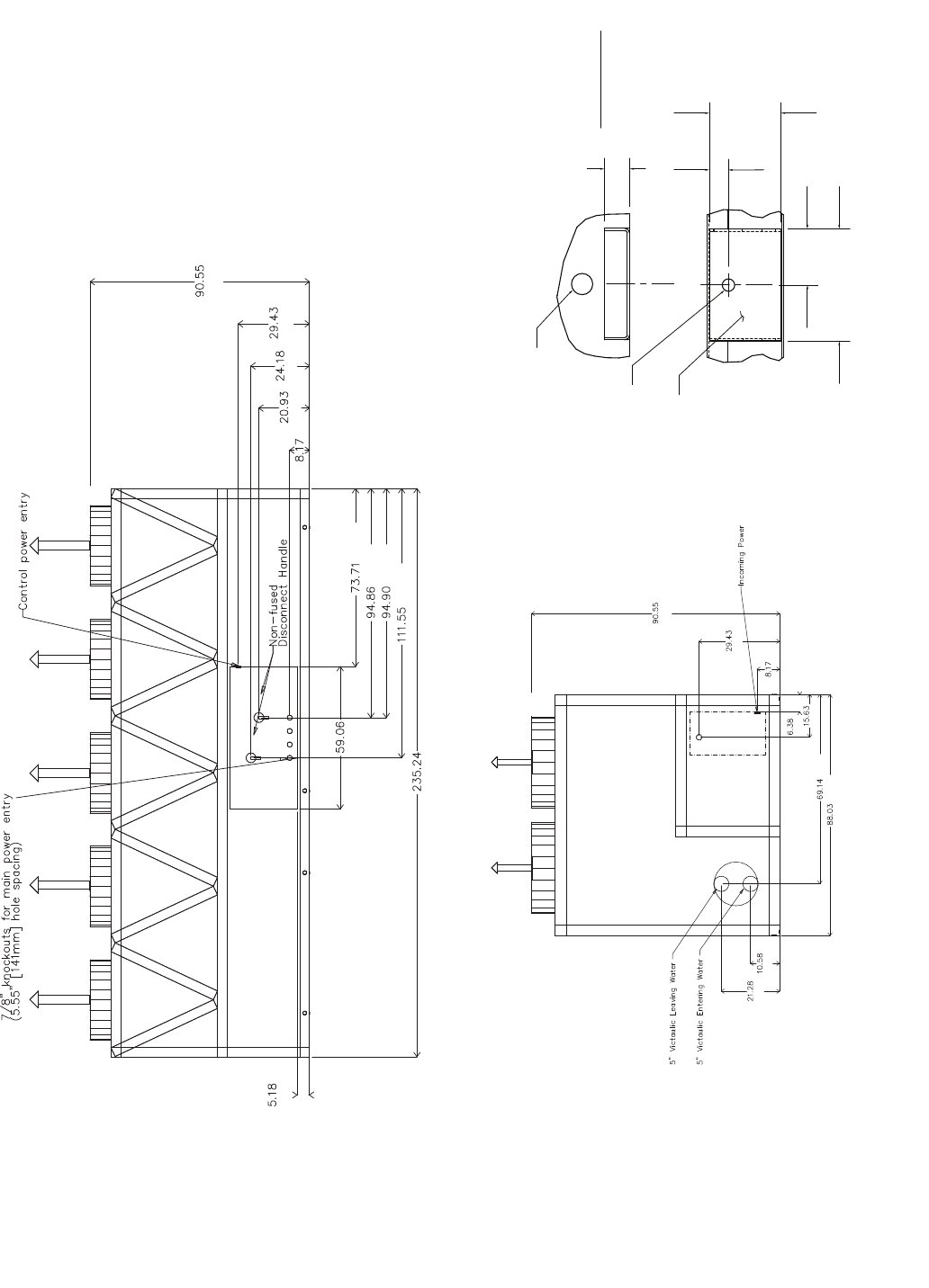
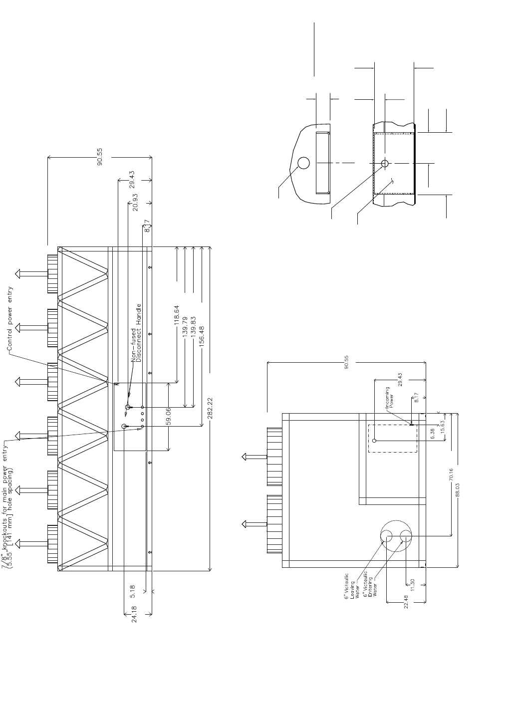
Fig. 2 — 30XA080 Air-Cooled Liquid Chiller Dimensions
NOTES:
1. Unit must have clearances as follows:
Top — Do not restrict
Sides and Ends — 6 ft (1.8 m) from solid surface.
2. Temperature relief devices are located on liquid line and econo-
mizer assemblies and have 1/4-in. flare connection.
3. 3/8-in. NPT vents and drains located in each cooler head at each
end of cooler.
4. Drawing depicts unit with single point power and standard two-
pass cooler. Refer to the Packaged Chiller Builder program for
other configurations.
5. Dimensions are shown in inches. Dimensions in [ ] are in
millimeters.
6. Allow 8 ft (2.4 m) on either side of unit for condenser coil removal.
a30-4402
TOP VIEW
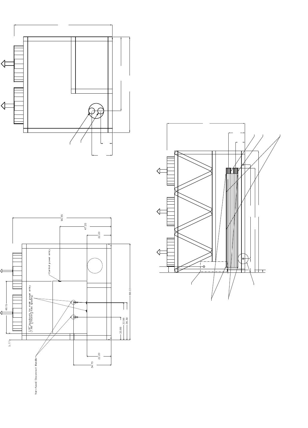
5
5" Victaulic Entering Water
5" Victaulic Leaving Water
90.55
[2300]
19.06
[484] 10.8
[274]
88.04
[2236]
68.06
[1729]
[1223]
[147]
[2300]
[1199]
[564]
[2236]
[863]
[874]
[531]
[564]
[881]
8.8
[224]
3/4 NPT Relief
Conn. Female
5" Victaulic
Entering Water
5" Victaulic
Leaving Water
Cooler Vent
3/8 NPT
Cooler Drain
3/8 NPT
Mounting Holes
Rigging Holes
(See Detail A)
Control Box All Voltages
90.55
[2300]
19.06
[484]
10.8
[274]
141.22
[3587]
121.17
[3078]
109.03
[2769]
16.1
[409]
3.15
[80]
a30-4403
LEFT END VIEW RIGHT END VIEW
FRONT VIEW
Fig. 2 — 30XA080 Air-Cooled Liquid Chiller Dimensions (cont)
6
A
[1475]
[1729]
[2236]
[913]
[508]
[1270]
[4780]
[3070]
B
[140]
[2769]
[80]
[863]
NOTES:
1. Unit must have clearances as follows:
Top — Do not restrict
Sides and Ends — 6 ft (1.8 m) from solid surface.
2. Temperature relief devices are located on liquid line and economizer assem-
blies and have 1/4-in. flare connection.
3. 3/8-in. NPT vents and drains located in each cooler head at each end of cooler.
4. Drawing depicts unit with single-point power and standard two-pass cooler.
Refer to the Packaged Chiller Builder program for other configurations.
5. Dimensions are shown in inches. Dimensions in [ ] are in millimeters.
6. Allow 8 ft (2.4 m) on either side of unit for condenser coil removal.
30XA UNIT A B
090 44.11 [1120] 86.93 [2208]
100 44.11 [1120] 87.22 [2215]
110 44.11 [1120] 87.62 [2226]
120 44.11 [1120] 87.12 [2213]
a30-4404
3.93
7.88
[200]
DETAIL "A"
MOUNTING PLATE
CONTACT SURFACE
TYPICAL 4 PLACES
[100]
MOUNTING HOLE
0.875 DIA.[22.2]
MOUNTING
PLATE
1.50 DIA. [38.1]
RIGGING HOLE
[127]
5.0
[33]
1.31
1.75
[44]
TOP VIEW
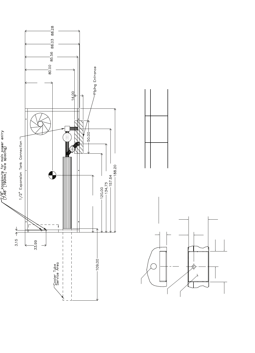
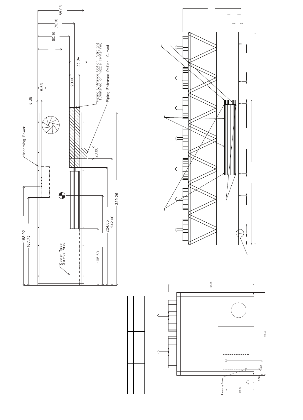
Fig. 3 — 30XA090-120 Air-Cooled Liquid Chiller without Pump Dimensions
7
[2300]
[1729]
[2236]
[274]
[484]
[2300]
[1199]
[564]
[2236]
[874]
[863]
[531]
[564]
[881]
[147]
[1223]
[2300]
[484]
[274]
[1982]
[4780]
[1982]
[3070]
[80]
[564]
[409]
8.8
[224]
a30-4405
RIGHT END VIEWLEFT END VIEW
FRONT VIEW
Fig. 3 — 30XA090-120 Air-Cooled Liquid Chiller without Pump Dimensions (cont)
8
A
[2032] [2173] [2236] [2242]
[356]
[1270]
[4780]
[4002]
[3422]
B
[3048]
[2769]
[80]
[863]
NOTES:
1. Unit must have clearances as follows:
Top — Do not restrict
Sides and Ends — 6 ft (1.8 m) from solid surface.
2. Temperature relief devices are located on liquid line and economizer assem-
blies and have 1/4-in. flare connection.
3. 3/8-in. NPT vents and drains located in each cooler head at each end of cooler.
4. Drawing depicts unit with single-point power and standard two-pass cooler.
Refer to the Packaged Chiller Builder program for other configurations.
5. Dimensions are shown in inches. Dimensions in [ ] are in millimeters.
6. Allow 8 ft (2.4 m) on either side of unit for condenser coil removal.
30XA UNIT A B
090 44.11 [1120] 86.93 [2208]
100 44.11 [1120] 87.22 [2215]
110 44.11 [1120] 87.62 [2226]
120 44.11 [1120] 87.12 [2213]
a30-4404
3.93
7.88
[200]
DETAIL "A"
MOUNTING PLATE
CONTACT SURFACE
TYPICAL 4 PLACES
[100]
MOUNTING HOLE
0.875 DIA.[22.2]
MOUNTING
PLATE
1.50 DIA. [38.1]
RIGGING HOLE
[127]
5.0
[33]
1.31
1.75
[44]
TOP VIEW
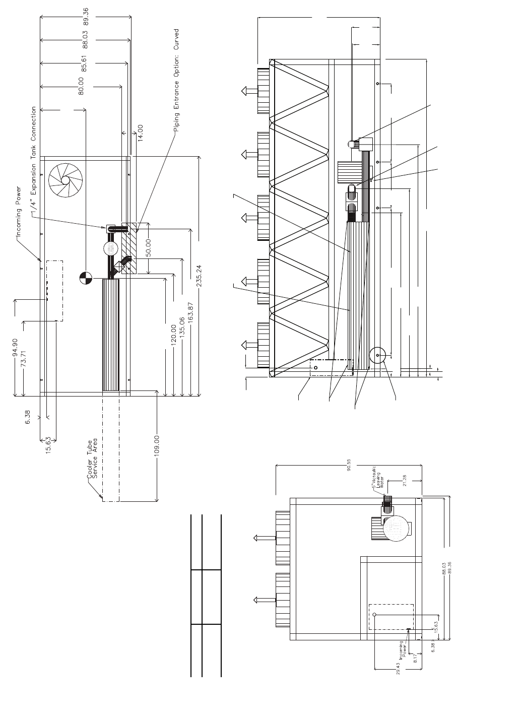
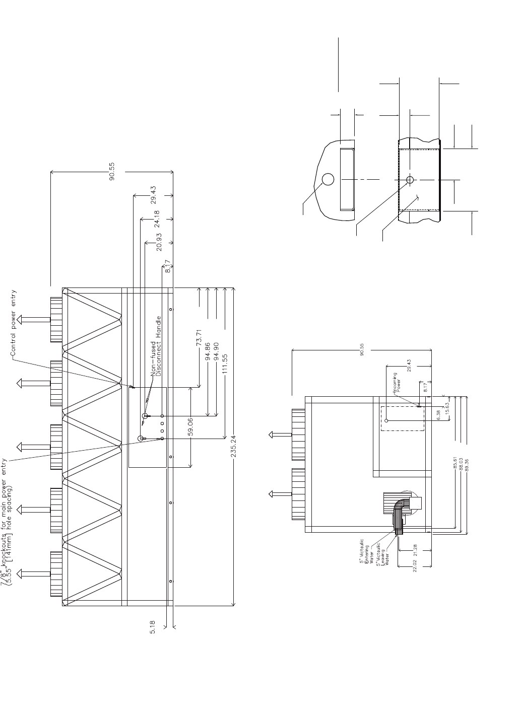
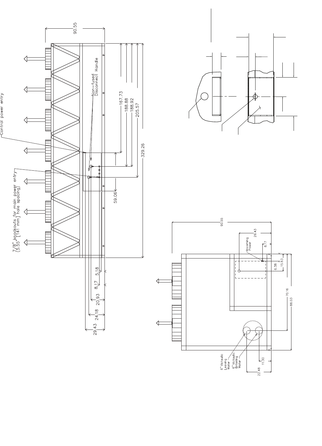
Fig. 4 — 30XA090-120 Air-Cooled Liquid Chiller with Pump Dimensions
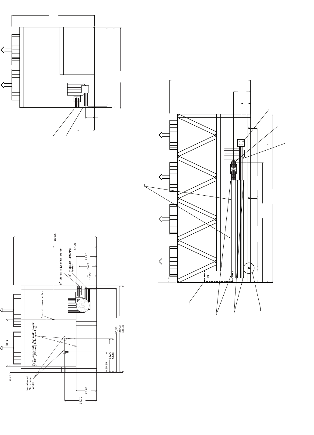
9
90.55
[2300]
19.06
[484]
10.27
[261]
88.04
[2236]
88.28
[2242]
85.56
[2173]
5" Victaulic Leaving Water
5" Victaulic Entering Water
[147]
[1223]
[881]
[564]
[531]
[863]
[874]
[2173]
[2236]
[2242]
[261]
[484] [564]
[1199]
[2300]
3/4 NPT Relief Conn. Female
Cooler Vent
3/8 NPT
Cooler Drain
3/8 NPT
Mounting Holes
Rigging Holes
(See Detail A)
Control Box All Voltages
90.55
[2300]
19.06
[484]
10.27
[261]
188.2
[4780]
157.54
[4002]
78.02
[1982] 78.02
[1982]
16.1
[409]
8.8
[224]
134.73
[3422]
5" Victaulic Entering Water
5" Victaulic Leaving Water
Drain
in
a30-4405
LEFT END VIEW RIGHT END VIEW
FRONT VIEW
Fig. 4 — 30XA090-120 Air-Cooled Liquid Chiller with Pump Dimensions (cont)
10
[2300]
[541]
[269]
[5975]
[1475]
[863]
[3086]
[2769]
[409]
[2410]
[1872]
[162]
[397]
[148]
[2769]
[508]
B
[3086]
[3810]
[5975]
[508]
[885]
[2236]
[1756]
[1502]
A
NOTES:
1. Unit must have clearances as follows:
Top — Do not restrict
Sides and Ends — 6 ft (1.8 m) from solid
surface.
2. Temperature relief devices are located on
liquid line and economizer assemblies and
have 1/4-in. flare connection.
3. 3/8-in. NPT vents and drains located in
each cooler head at each end of cooler.
4. Drawing depicts unit with single-point
power, standard two-pass cooler, and
nominal voltage range of 380 to 575 v.
Refer to the Packaged Chiller Builder pro-
gram for other configurations.
5. Dimensions are shown in inches. Dimen-
sions in [ ] are in millimeters.
6. Allow 8 ft (2.4 m) on either side of unit for
condenser coil removal.
30XA UNIT A B
140 44.63 [1134] 115.88 [2943]
160 44.61 [1133] 115.64 [2937]
a30-4404
TOP VIEW
FRONT VIEW
LEFT END VIEW
[2300]
[2236]
[748]
[208]
[162] [397]
Fig. 5 — 30XA140,160 Air-Cooled Liquid Chiller without Pump Dimensions
11
[132]
[1500]
[5975]
[1872]
[2409]
[2410]
[2833]
[2300]
[748]
[614]
[532]
[208]
[2300]
[748]
[208]
[162]
[397]
[1756]
[2236]
[541]
[269]
a30-4407
3.93
7.88
[200]
DETAIL "A"
MOUNTING PLATE
CONTACT SURFACE
TYPICAL 4 PLACES
[100]
MOUNTING HOLE
0.875 DIA.[22.2]
MOUNTING
PLATE
1.50 DIA. [38.1]
RIGGING HOLE
[127]
5.0
[33]
1.31
1.75
[44]
BACK VIEW
RIGHT END VIEW
Fig. 5 — 30XA140,160 Air-Cooled Liquid Chiller without Pump Dimensions (cont)
12
[748]
[208]
[162] [397] [2236]
[2270]
[541]
[2300]
A
[2032] [2174] [2236] [2270]
[356]
[1270]
[2769]
[397]
[162]
[1872]
[2410]
[5975]
[4162]
[3431]
[3048]
B
3/4 NPT Relief Conn. Female
5" Victaulic Entering
5" Victaulic Leaving Water
Water
Cooler Drain
3/8 NPT
Cooler Vent
3/8 NPT
Mounting Holes
Rigging Holes
(See Detail A)
Control Box
incoming power
supply (200,230v) 90.55
[2300]
22.02
[559]
235.24
[5975]
121.49
[3086]
109.03
[2769]
58.08
[1475]
33.96
[863]
16.1
[409]
8.8
[224]
7.2
[182]
2.8 [72]
21.28
[541]
135.03
[3431] 163.87
[4162]
in
out
Drain
a30-4407
TOP VIEW
FRONT VIEW
LEFT END VIEW
NOTES:
1. Unit must have clearances as follows:
Top — Do not restrict
Sides and Ends — 6 ft (1.8 m) from solid
surface.
2. Temperature relief devices are located on
liquid line and economizer assemblies and
have 1/4-in. flare connection.
3. 3/8-in. NPT vents and drains located in
each cooler head at each end of cooler.
4. Drawing depicts unit with single-point
power, standard two-pass cooler, and
nominal voltage range of 380 to 575 v.
Refer to the Packaged Chiller Builder pro-
gram for other configurations.
5. Dimensions are shown in inches. Dimen-
sions in [ ] are in millimeters.
6. Allow 8 ft (2.4 m) on either side of unit for
condenser coil removal.
30XA UNIT A B
140 44.63 [1134] 115.88 [2943]
160 44.61 [1133] 115.64 [2937]
Fig. 6 — 30XA140,160 Air-Cooled Liquid Chiller with Pump Dimensions
13
[559] [541]
[2174]
[2236]
[2270]
[162]
[397]
[208]
[748]
[2300]
a30-4407
3.93
7.88
[200]
DETAIL "A"
MOUNTING PLATE
CONTACT SURFACE
TYPICAL 4 PLACES
[100]
MOUNTING HOLE
0.875 DIA.[22.2]
MOUNTING
PLATE
1.50 DIA. [38.1]
RIGGING HOLE
[127]
5.0
[33]
1.31
1.75
[44]
BACK VIEW
RIGHT END VIEW
[132]
[1500]
[5975]
[1872]
[2409]
[2410]
[2833]
[2300]
[748]
[614]
[532]
[208]
Fig. 6 — 30XA140,160 Air-Cooled Liquid Chiller with Pump Dimensions (cont)
14
[459] [1475] [863] [1982]
[4502]
[7168]
[1982]
[287]
[571]
[2300]
[1555]
[2769]
B
[4502]
[7168]
[914]
[508] [860]
[162]
A
[1528] [1782]
[2236]
NOTES:
1. Unit must have clearances as follows:
Top — Do not restrict
Sides and Ends — 6 ft (1.8 m) from solid
surface.
2. Temperature relief devices are located on
liquid line and economizer assemblies and
have 1/4-in. flare connection.
3. 3/8-in. NPT vents and drains located in
each cooler head at each end of cooler.
4. Drawing depicts unit with single point
power, standard two-pass cooler, and a
nominal voltage range of 380 to 575 v.
Refer to the Packaged Chiller Builder pro-
gram for other configurations.
5. Dimensions are shown in inches. Dimen-
sions in [ ] are in millimeters.
6. Allow 8 ft (2.4 m) on either side of unit for
condenser coil removal.
30XA UNIT A B
180 46.12 [1171] 143.04 [3633]
200 46.15 [1172] 142.97 [3631]
a30-4408
TOP VIEW
FRONT VIEW
LEFT END VIEW
[2300]
[2236]
[748]
[208]
[162] [397]
Fig. 7 — 30XA180,200 Air-Cooled Liquid Chiller Dimensions
15
[2300]
[748]
[208]
[162]
[397]
[1782]
[2236]
[287]
[571]
[2300]
[748]
[532]
[208]
[1500] [3013]
[3551]
[3552]
[3975]
[7168]
[132]
[614]
a30-4174
3.93
7.88
[200]
DETAIL "A"
MOUNTING PLATE
CONTACT SURFACE
TYPICAL 4 PLACES
[100]
MOUNTING HOLE
0.875 DIA.[22.2]
MOUNTING
PLATE
1.50 DIA. [38.1]
RIGGING HOLE
[127]
5.0
[33]
1.31
1.75
[44]
BACK VIEW
RIGHT END VIEW
Fig. 7 — 30XA180,200 Air-Cooled Liquid Chiller Dimensions (cont)
16
3/4 NPT Relief Conn. Female
6" Victaulic Entering Water
6" Victaulic Leaving Water
Cooler Vent
3/8 NPT
Cooler Drain
3/8 NPT
Mounting Holes
Rigging Holes
(See Detail A)
90.55
[2300]
22.48
[571]
11.3
[287]
329.26 [8363]
224.65 [5706]
109.03 [2769]58.08 [1475] 58.08 [1475]
33.97 [863]33.96 [863]
18.07
[459]
[162]
[397]
A
[1528] [1782]
[2236]
[508]
[860]
[508]
[4799]
[4260]
[8363]
[6147]
[5706]
B
[2758]
NOTES:
1. Unit must have clearances as follows:
Top — Do not restrict
Sides and Ends — 6 ft (1.8 m) from solid
surface.
2. Temperature relief devices are located on liq-
uid line and economizer assemblies and have
1/4-in. flare connection.
3. 3/8-in. NPT vents and drains located in each
cooler head at each end of cooler.
4. Drawing depicts unit with single point power,
standard two-pass cooler and nominal voltage
range of 380 to 575 v. Refer to the Packaged
Chiller Builder program for other configura-
tions.
5. Dimensions are shown in inches. Dimensions
in [ ] are in millimeters.
6. Allow 8 ft (2.4 m) on either side of unit for con-
denser coil removal.
30XA UNIT A B
220 46.17 [1173] 171.42 [4354]
240 46.23 [1174] 170.83 [4339]
a30-4409
TOP VIEW
LEFT END VIEW FRONT VIEW
[2300]
[2236]
[748]
[208]
[162] [397]
Fig. 8 — 30XA220,240 Air-Cooled Liquid Chiller Dimensions
17
[1500]
[748] [614] [532] [208] [132]
[2300]
[4260]
[4798]
[4799]
[5221]
[8363]
a30-4176
3.93
7.88
[200]
DETAIL "A"
MOUNTING PLATE
CONTACT SURFACE
TYPICAL 4 PLACES
[100]
MOUNTING HOLE
0.875 DIA.[22.2]
MOUNTING
PLATE
1.50 DIA. [38.1]
RIGGING HOLE
[127]
5.0
[33]
1.31
1.75
[44]
BACK VIEW
RIGHT END VIEW
[2300]
[748]
[208]
[162]
[397]
[1782]
[2236]
[287]
[571]
Fig. 8 — 30XA220,240 Air-Cooled Liquid Chiller Dimensions (cont)
18
3/4 NPT Relief Conn. Female
8" Victaulic Entering Water
8" Victaulic Leaving WaterCooler Vent
3/8 NPT
Cooler Drain
3/8 NPT
Mounting Holes
Rigging Holes
(See Detail A)
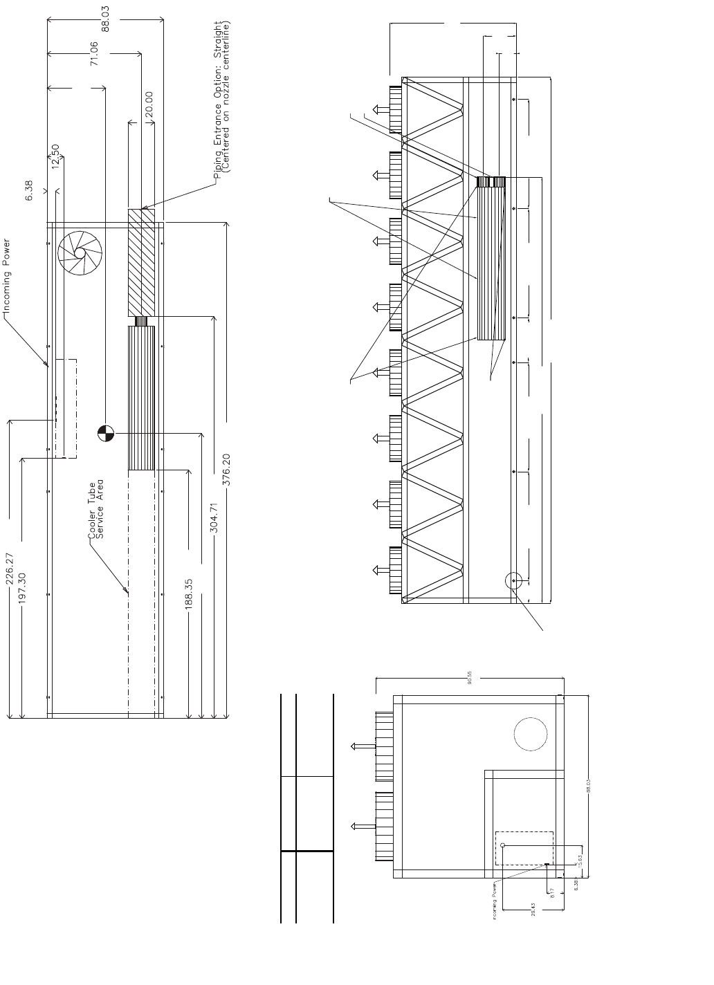
90.55
[2300]
23.63
[600]
12.21
[310]
376.2 [9555]
304.71 [7740]
78.02 [1982]
78.02 [1982] 78.02 [1982]78.02 [1982] 31.96 [812]
16.1
[409]
[162]
[317]
A
[1805]
[2236]
[508]
[9555]
[7740]
B
[4784]
[5011]
[5747]
NOTES:
1. Unit must have clearances as follows:
Top — Do not restrict
Sides and Ends — 6 ft (1.8 m) from
solid surface.
2. Temperature relief devices are located
on liquid line and economizer assem-
blies and have 1/4-in. flare connection.
3. 3/8-in. NPT vents and drains located in
each cooler head at each end of
cooler.
4. Drawing depicts unit with single point
power and standard two-pass cooler.
Refer to the Packaged Chiller Builder
program for other configurations.
5. Dimensions are shown in inches.
Dimensions in [ ] are in millimeters.
6. Allow 8 ft (2.4 m) on either side of unit
for condenser coil removal.
30XA UNIT A B
260 44.22 [1123] 216.16 [5490]
280 44.30 [1125] 215.86 [5483]
300 44.32 [1126] 216.18 [5491]
a30-4177
TOP VIEW
LEFT END VIEW
FRONT VIEW
[2300]
[2236]
[748]
[208]
[162] [397]
Fig. 9 — 30XA260-300 Air-Cooled Liquid Chiller Dimensions
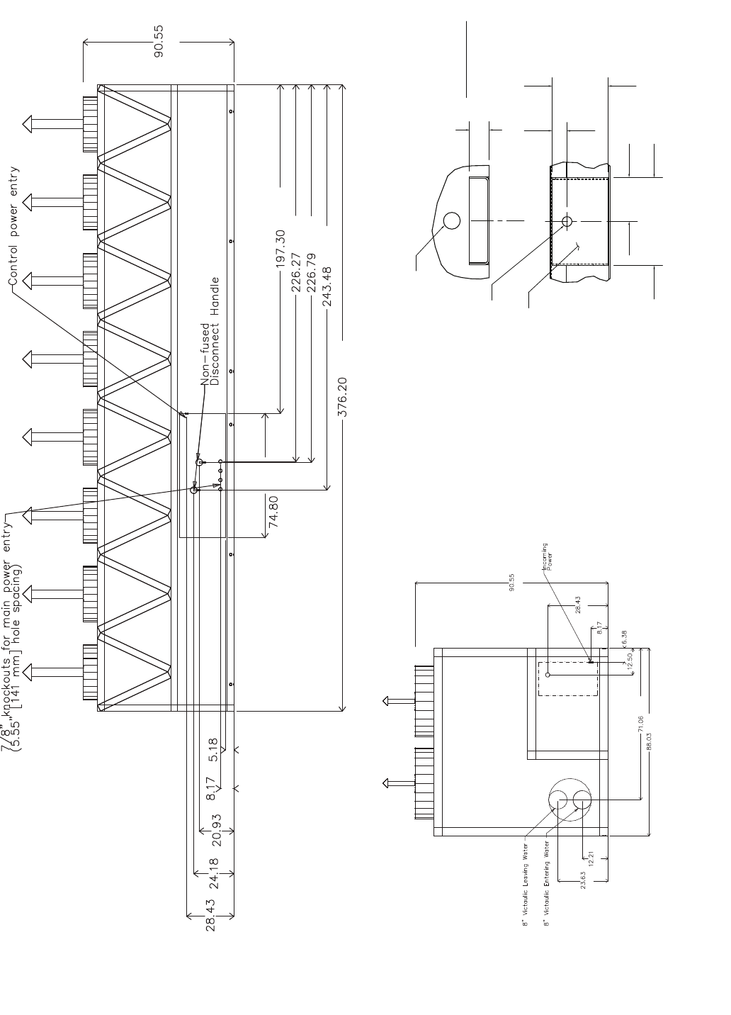
19
[722] [614] [532] [208] [132]
[1900]
[9555]
[6184]
[5760]
[5747]
[5011]
[2300]
[2300]
[722]
[208]
[317]
[162]
[1805]
[2236]
[600]
[310]
a30-4178
3.93
7.88
[200]
DETAIL "A"
MOUNTING PLATE
CONTACT SURFACE
TYPICAL 4 PLACES
[100]
MOUNTING HOLE
0.875 DIA.[22.2]
MOUNTING
PLATE
1.50 DIA. [38.1]
RIGGING HOLE
[127]
5.0
[33]
1.31
1.75
[44]
BACK VIEW
RIGHT END VIEW
Fig. 9 — 30XA260-300 Air-Cooled Liquid Chiller Dimensions (cont)
20
3/4 NPT Relief Conn. Female
8" Victaulic Entering Water
8" Victaulic Leaving Water
Cooler Vent
3/8 NPT
Cooler Drain
3/8 NPT
Mounting Holes
Rigging Holes
(See Detail A)
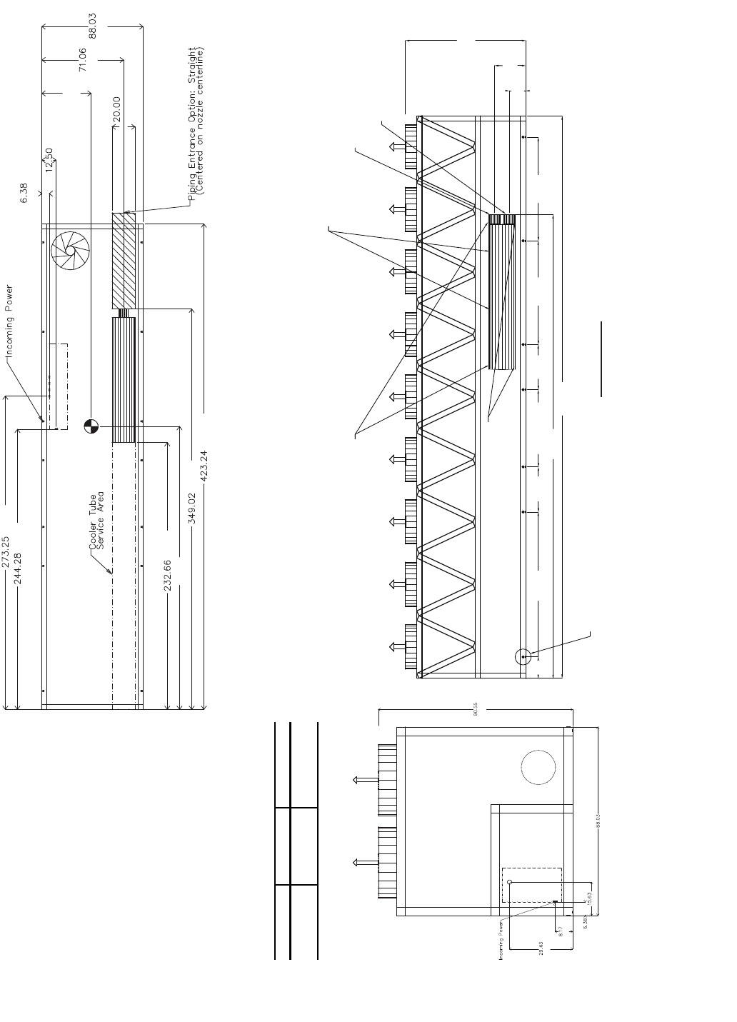
90.55
[2300]
23.63
[600]
12.21
[310]
423.24
[10750]
349.02
[8865]
109.03
[2769] 78.02
[1982]
78.02
[1982]
58.08 [1475] 33.97
[863]
33.96
[863]
16.1
[409]
FRONT VIEW
[162]
[317]
A
[1805]
[2236]
[508]
[10750]
[8865]
B
[5910]
[6205]
[6941]
NOTES:
1. Unit must have clearances as follows:
Top — Do not restrict
Sides and Ends — 6 ft (1.8 m) from solid
surface.
2. Temperature relief devices are located on
liquid line and economizer assemblies and
have 1/4-in. flare connection.
3. 3/8-in. NPT vents and drains located in each
cooler head at each end of cooler.
4. Drawing depicts unit with single point power
and standard two-pass cooler. Refer to the
Packaged Chiller Builder program for other
configurations.
5. Dimensions are shown in inches. Dimen-
sions in [ ] are in millimeters.
6. Allow 8 ft (2.4 m) on either side of unit for
condenser coil removal.
30XA UNIT A B
325 42.92 [1090] 246.16 [6252]
350 42.92 [1090] 246.72 [6267]
TOP VIEW
FRONT VIEW
LEFT END VIEW
[2300]
[2236]
[748]
[208]
[162] [397]
Fig. 10 — 30XA325,350 Air-Cooled Liquid Chiller Dimensions
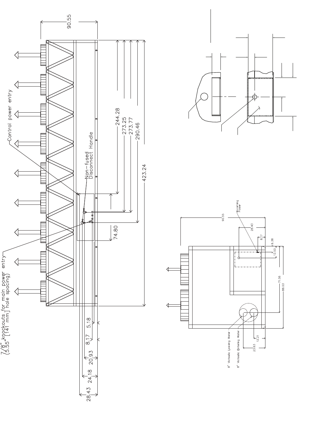
21
[2300]
[6205]
[6941]
[6954]
[7378]
[10750]
[1900]
[722] [614] [532] [208] [132]
a30-4180
3.93
7.88
[200]
DETAIL "A"
MOUNTING PLATE
CONTACT SURFACE
TYPICAL 4 PLACES
[100]
MOUNTING HOLE
0.875 DIA.[22.2]
MOUNTING
PLATE
1.50 DIA. [38.1]
RIGGING HOLE
[127]
5.0
[33]
1.31
1.75
[44]
BACK VIEW
RIGHT END VIEW
[2300]
[722]
[208]
[317]
[162]
[1805]
[2236]
[600]
[310]
Fig. 10 — 30XA325,350 Air-Cooled Liquid Chiller Dimensions (cont)
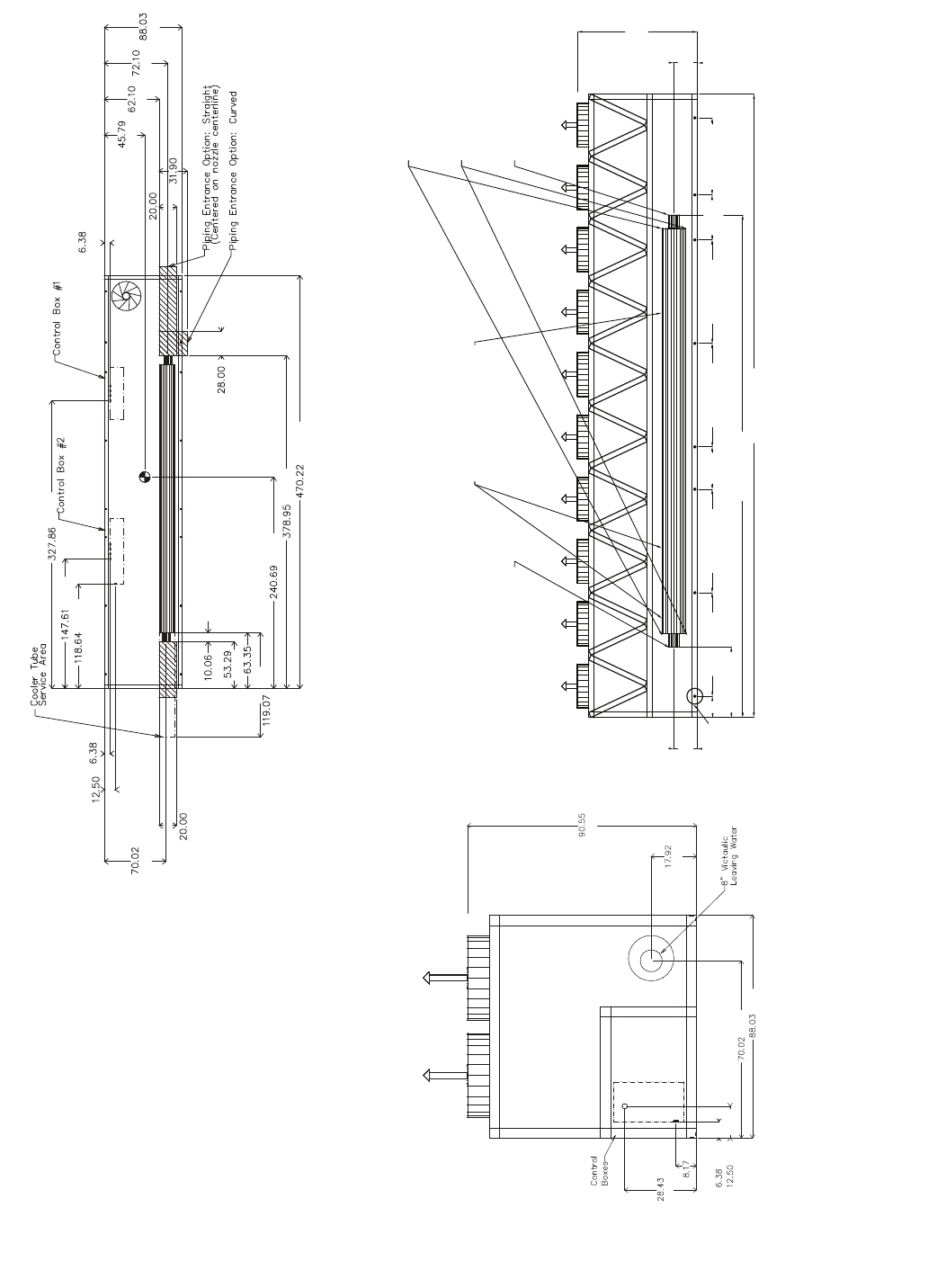
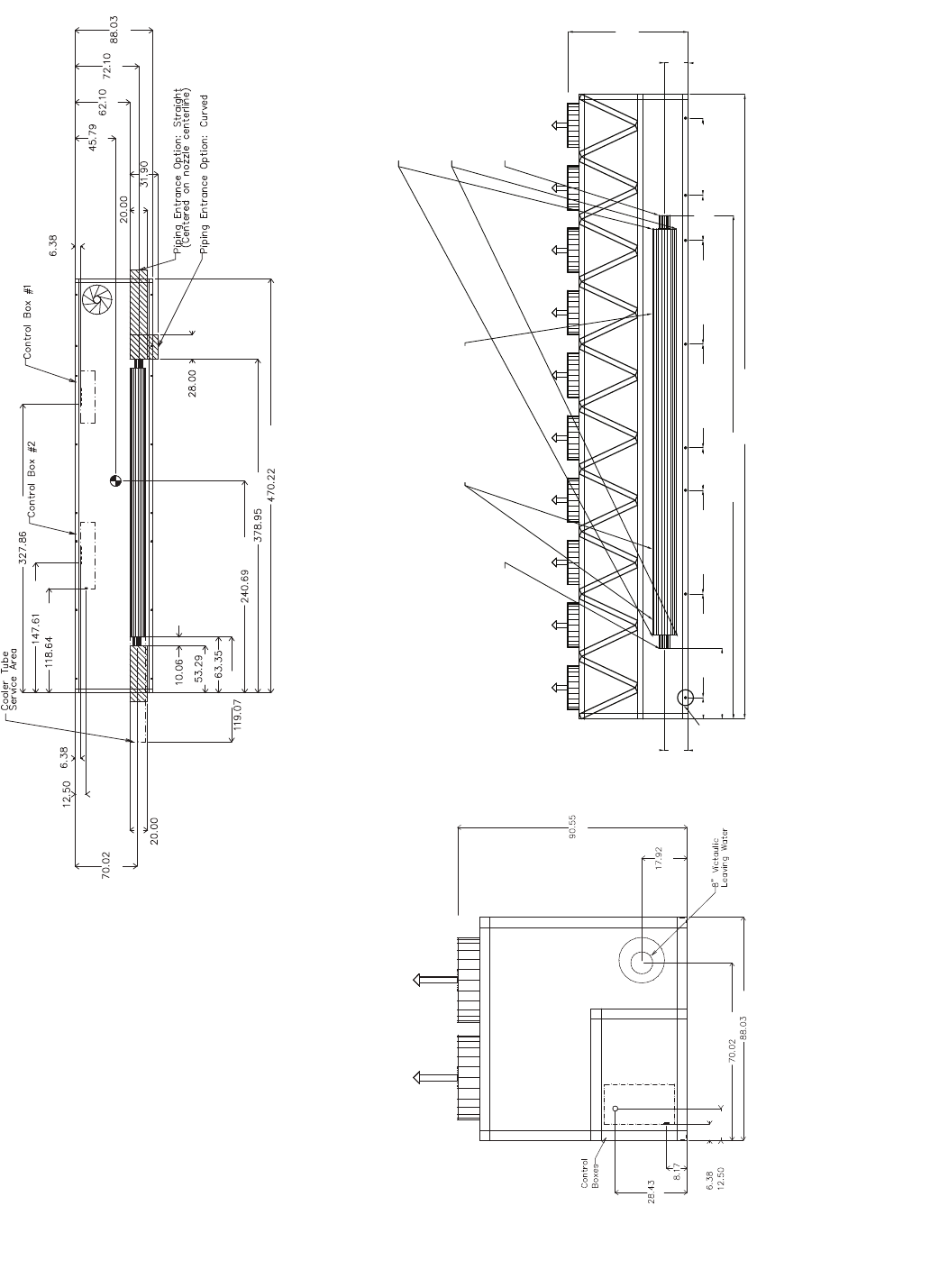
22
[2300]
[455]
[1779]
[2236]
[162]
[317]
[208]
[722]
3/4 NPT Relief Conn. Female
8" Victaulic Entering Water8" Victaulic Leaving Water
Cooler Vent 3/8 NPT
located in cooler heads
Cooler Drain 3/8 NPT
located in cooler heads
Mounting Holes
Rigging Holes
(See Detail A)
90.55
[2300]
17.92
[455]
17.92
[455]
470.22 [11944]
378.95 [9625]
53.29 [1354]
78.02 [1982]78.02 [1982] 78.02 [1982]78.02 [1982] 58.08 [1475]
33.93
[862]
31.96
[812]
16.1
[409]
[162]
[508]
[810]
[1163]
[1577] [1831] [2236]
[711]
[11944]
[9625]
[6114]
[3024]
[508]
[1779]
[317] [162]
[256]
[1354]
[1609]
[3013]
[3749]
[8328]
NOTES:
1. Unit must have clearances as follows:
Top — Do not restrict
Sides and Ends — 6 ft (1.8 m) from solid
surface.
2. Temperature relief devices are located on liq-
uid line and economizer assemblies and have
1/4-in. flare connection.
3. 3/8-in. NPT vents and drains located in each
cooler head at each end of cooler.
4. Drawing depicts unit with single point power
and standard one-pass cooler. Refer to the
Packaged Chiller Builder program for other
configurations.
5. Actual cooler consists of two separate coolers
piped in series at the factory. Piping may be
split for rigging.
6. Dimensions are shown in inches. Dimensions
in [ ] are in millimeters.
7. Allow 8 ft (2.4 m) on either side of unit for con-
denser coil removal.
a30-4181
TOP VIEW
LEFT END VIEW
FRONT VIEW
Fig. 11 — 30XA400 Air-Cooled Liquid Chiller with Single Point Connections Dimensions
23
[2300]
[722]
[208]
[162]
[317]
[1831]
[2236]
[455]
[2300]
[132] [208] [532] [614] [722]
[3013]
[3749]
[3763]
[4186]
[1900]
[7789]
[8328]
[8653]
[11944]
[1500]
[424] [208] [132]
a30-4182
BACK VIEW
RIGHT END VIEW
3.93
7.88
[200]
DETAIL "A"
MOUNTING PLATE
CONTACT SURFACE
TYPICAL 4 PLACES
[100]
MOUNTING HOLE
0.875 DIA.[22.2]
MOUNTING
PLATE
1.50 DIA. [38.1]
RIGGING HOLE
[127]
5.0
[33]
1.31
1.75
[44]
Fig. 11 — 30XA400 Air-Cooled Liquid Chiller with Single Point Connections Dimensions (cont)
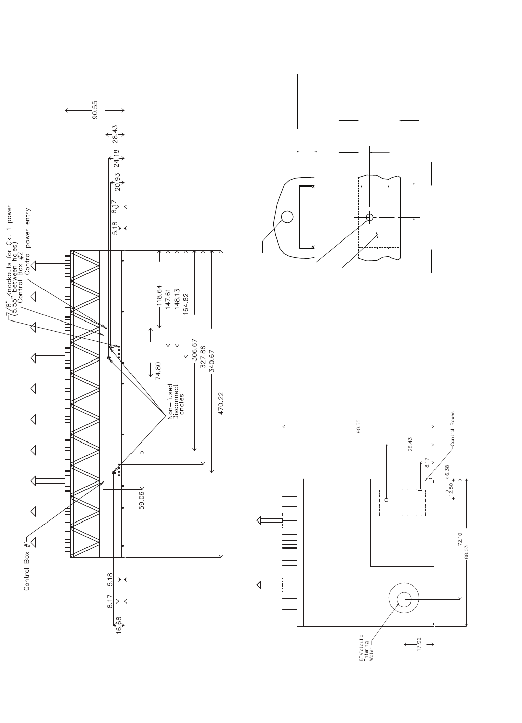
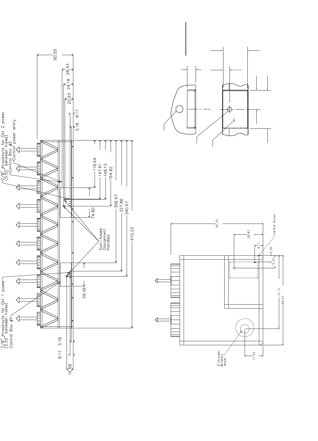
24
NOTES:
1. Unit must have clearances as follows:
Top — Do not restrict
Sides and Ends — 6 ft (1.8 m) from solid
surface.
2. Temperature relief devices are located on liq-
uid line and economizer assemblies and have
1/4-in. flare connection.
3. 3/8-in. NPT vents and drains located in each
cooler head at each end of cooler.
4. Drawing depicts unit with dual-point power
and standard one-pass cooler. Refer to the
Packaged Chiller Builder program for other
configurations.
5. Actual cooler consists of two separate coolers
piped in series at the factory. Piping may be
split for rigging.
6. Dimensions are shown in inches. Dimensions
in [ ] are in millimeters.
7. Allow 8 ft (2.4 m) on either side of unit for con-
denser coil removal.
a30-4181
TOP VIEW
LEFT END VIEW FRONT VIEW
[2300]
[455]
[1779]
[2236]
[162]
[317]
[208]
[722]
3/4 NPT Relief Conn. Female
8" Victaulic Entering Water8" Victaulic Leaving Water
Cooler Vent 3/8 NPT
located in cooler heads
Cooler Drain 3/8 NPT
located in cooler heads
Mounting Holes
Rigging Holes
(See Detail A)
90.55
[2300]
17.92
[455]
17.92
[455]
470.22 [11944]
378.95 [9625]
53.29 [1354]
78.02 [1982]78.02 [1982] 78.02 [1982]78.02 [1982] 58.08 [1475]
33.93
[862]
31.96
[812]
16.1
[409]
[162]
[508]
[810]
[1163]
[1577] [1831] [2236]
[711]
[11944]
[9625]
[6114]
[3024]
[508]
[1779]
[317] [162]
[256]
[1354]
[1609]
[3013]
[3749]
[8328]
Fig. 12 — 30XA400 Air-Cooled Liquid Chiller with Dual Point Connections Dimensions
25
[1500]
[1900]
[11944]
[8653]
[8328]
[7789]
[4186]
[3763]
[3749]
[3013]
[132] [208]
[532] [614] [722]
[2300]
[424]
[208] [132]
a30-4182
BACK VIEW
RIGHT END VIEW
3.93
7.88
[200]
DETAIL "A"
MOUNTING PLATE
CONTACT SURFACE
TYPICAL 4 PLACES
[100]
MOUNTING HOLE
0.875 DIA.[22.2]
MOUNTING
PLATE
1.50 DIA. [38.1]
RIGGING HOLE
[127]
5.0
[33]
1.31
1.75
[44]
[2300]
[722]
[208]
[162]
[317]
[1831]
[2236]
[455]
Fig. 12 — 30XA400 Air-Cooled Liquid Chiller with Dual Point Connections Dimensions (cont)
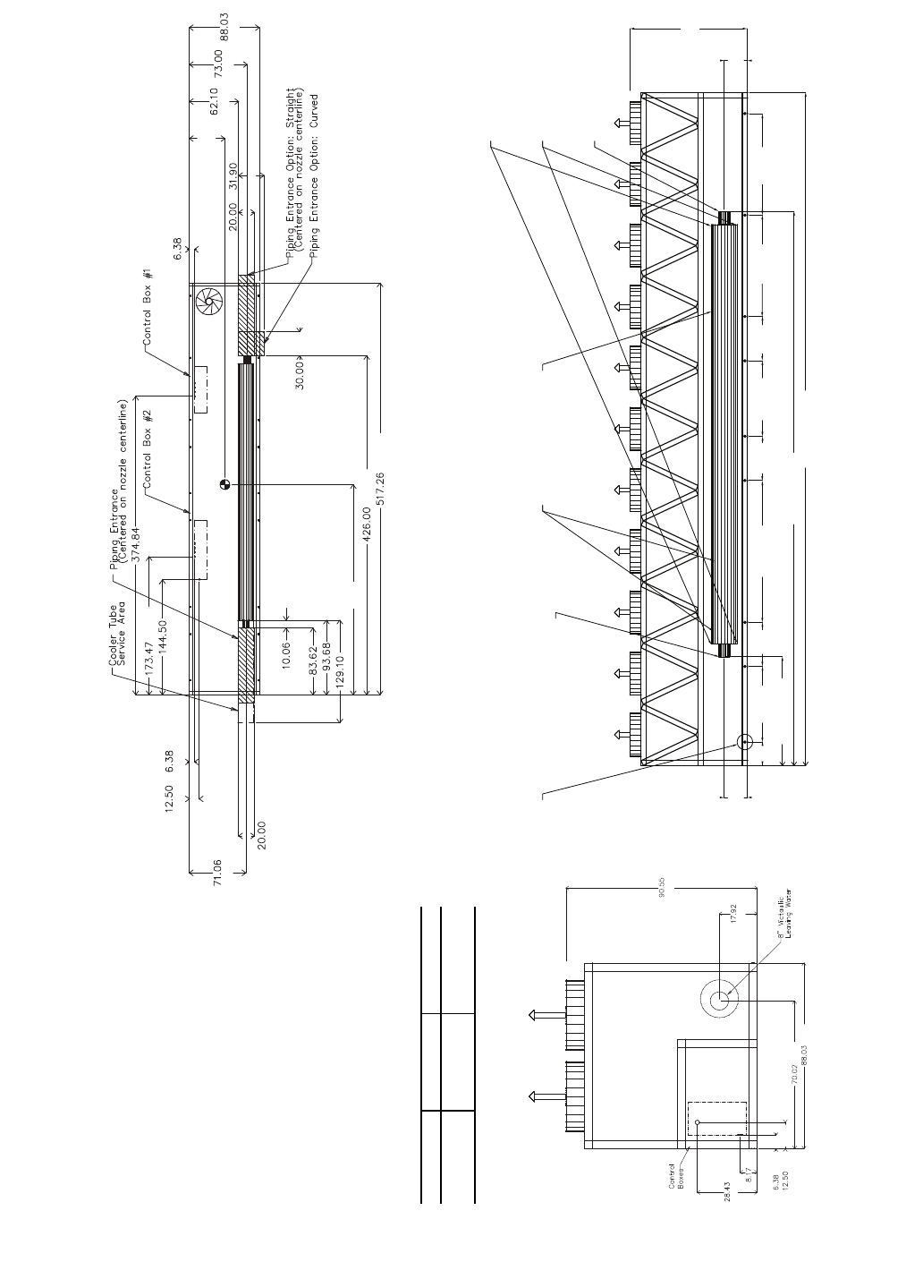
26
3/4 NPT Relief Conn. Female
8" Victaulic Entering Water
8" Victaulic Leaving Water
Cooler Vent 3/8 NPT
located in cooler heads
Cooler Drain 3/8 NPT
located in cooler heads
Mounting Holes
Rigging Holes
(See Detail A)
90.55
[2300]
17.92
[455]
17.92
[455]
517.26 [13138]
426.0 [10820]
83.62 [2124]
109.03
[2769] 78.02
[1982]
78.02
[1982]
58.08
[1475] 58.08
[1475]
33.97
[863]
33.97
[863]
33.96
[863]
18.07
[459]
[162]
[508] [810]
A
[1577] [1854] [2236]
[762]
[13138]
[10820]
B
[256]
[2124]
[2379]
[3279]
[508]
[1805]
[317] [162]
[9521]
[3670]
[4406]
NOTES:
1. Unit must have clearances as follows:
Top — Do not restrict
Sides and Ends — 6 ft (1.8 m) from solid
surface.
2. Temperature relief devices are located on
liquid line and economizer assemblies and
have 1/4-in. flare connection.
3. 3/8-in. NPT vents and drains located in
each cooler head at each end of cooler.
4. Drawing depicts unit with single-point
power and standard one-pass cooler.
Refer to the Packaged Chiller Builder pro-
gram for other configurations.
5. Actual cooler consists of two separate
coolers piped in series at the factory. Pip-
ing may be split for rigging.
6. Dimensions are shown in inches. Dimen-
sions in [ ] are in millimeters.
7. Allow 8 ft (2.4 m) on either side of unit for
condenser coil removal.
30XA UNIT A B
450 44.71 [1136] 264.7 [6723]
500 44.78 [1137] 263.99 [6705]
a30-4183
TOP VIEW
FRONT VIEWLEFT END VIEW
[2300]
[455]
[1779]
[2236]
[162]
[317]
[208]
[722]
Fig. 13 — 30XA450,500 Air-Cooled Liquid Chiller with Single Point Connections Dimensions
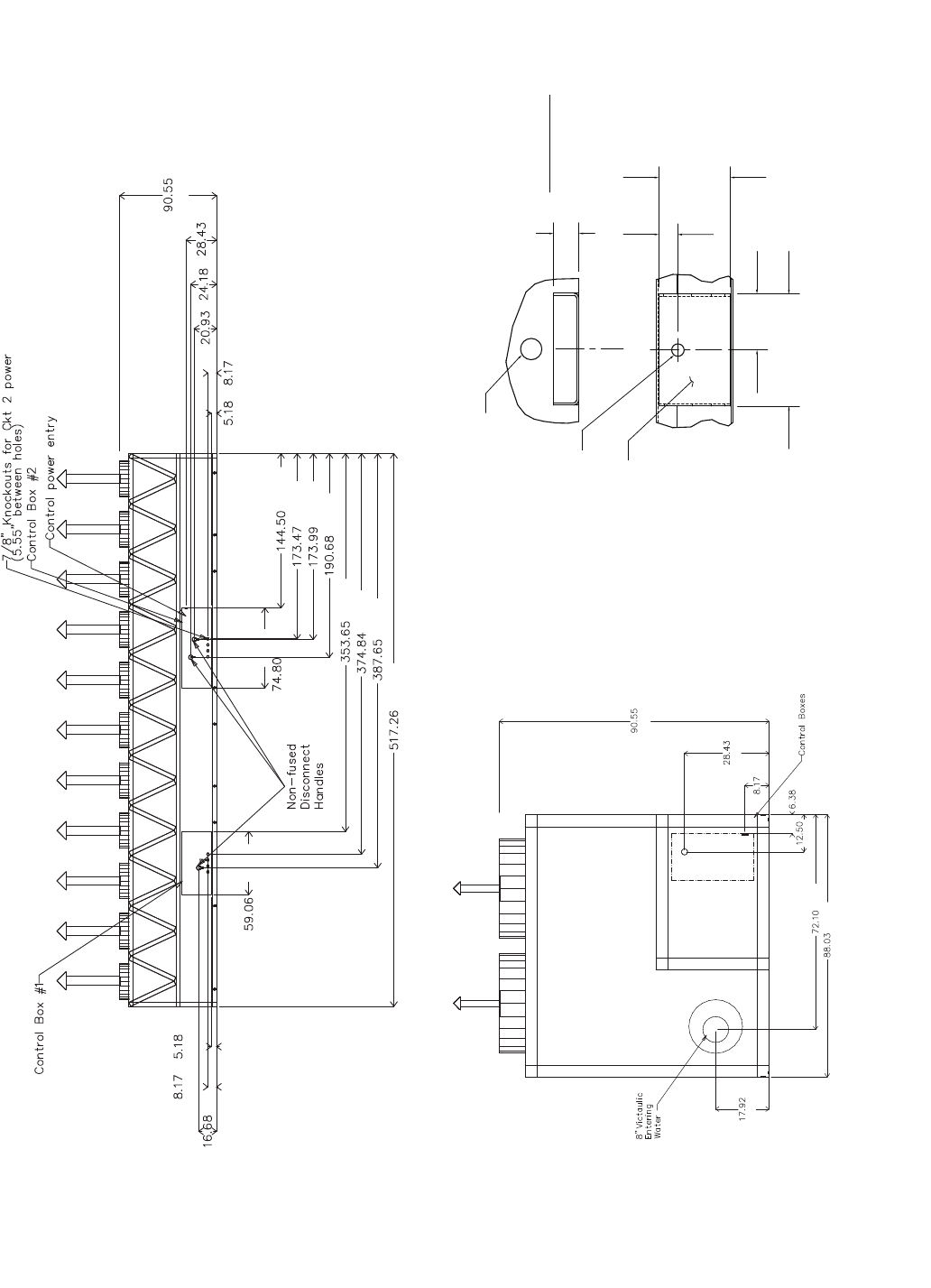
27
[2300]
[722]
[614]
[532]
[132] [208]
[1900] [3670]
[4406]
[4419]
[4843]
[8983]
[9521]
[9846]
[13138]
[1500]
[424]
[208] [132]
a30-4184
BACK VIEW
RIGHT END VIEW
3.93
7.88
[200]
DETAIL "A"
MOUNTING PLATE
CONTACT SURFACE
TYPICAL 4 PLACES
[100]
MOUNTING HOLE
0.875 DIA.[22.2]
MOUNTING
PLATE
1.50 DIA. [38.1]
RIGGING HOLE
[127]
5.0
[33]
1.31
1.75
[44]
[2300]
[722]
[208]
[162]
[317]
[1831]
[2236]
[455]
Fig. 13 — 30XA450,500 Air-Cooled Liquid Chiller with Single Point Connections Dimensions (cont)
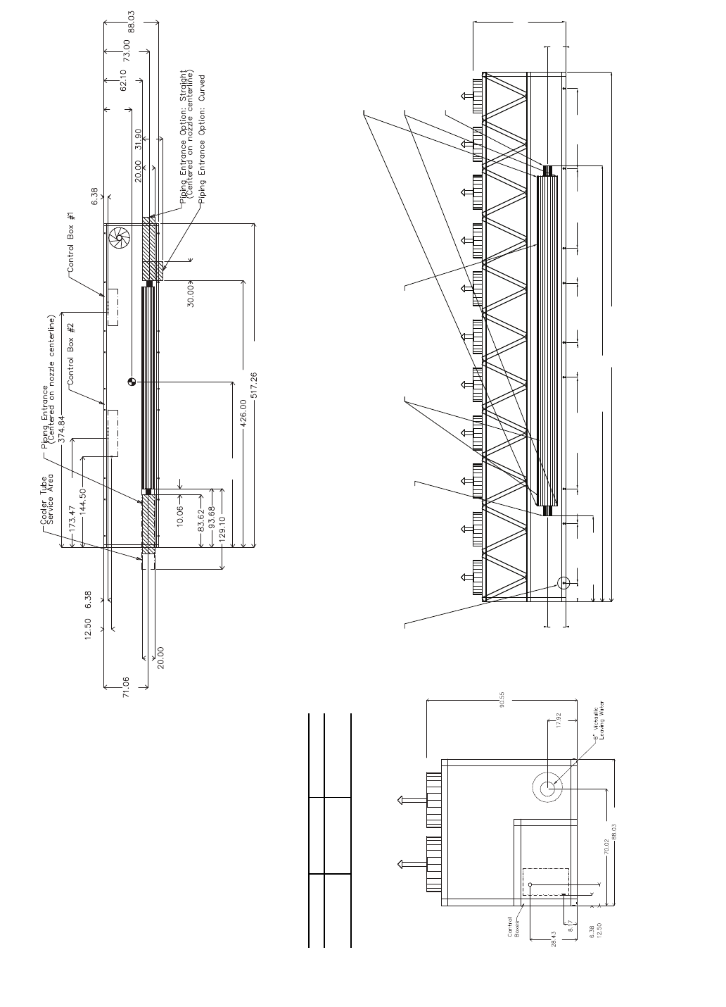
28
NOTES:
1. Unit must have clearances as follows:
Top — Do not restrict
Sides and Ends — 6 ft (1.8 m) from solid
surface.
2. Temperature relief devices are located on
liquid line and economizer assemblies and
have 1/4-in. flare connection.
3. 3/8-in. NPT vents and drains located in
each cooler head at each end of cooler.
4. Drawing depicts unit with dual-point power
and standard one-pass cooler. Refer to
the Packaged Chiller Builder program for
other configurations.
5. Actual cooler consists of two separate
coolers piped in series at the factory. Pip-
ing may be split for rigging.
6. Dimensions are shown in inches. Dimen-
sions in [ ] are in millimeters.
7. Allow 8 ft (2.4 m) on either side of unit for
condenser coil removal.
30XA UNIT A B
450 44.71 [1136] 264.7 [6723]
500 44.78 [1137] 263.99 [6705]
a30-4183
3/4 NPT Relief Conn. Female
8" Victaulic Entering Water
8" Victaulic Leaving Water
Cooler Vent 3/8 NPT
located in cooler heads
Cooler Drain 3/8 NPT
located in cooler heads
Mounting Holes
Rigging Holes
(See Detail A)
90.55
[2300]
17.92
[455]
17.92
[455]
517.26 [13138]
426.0 [10820]
83.62 [2124]
109.03
[2769] 78.02
[1982]
78.02
[1982]
58.08
[1475] 58.08
[1475]
33.97
[863]
33.97
[863]
33.96
[863]
18.07
[459]
TOP VIEW
FRONT VIEWLEFT END VIEW
[2300]
[455]
[1779]
[2236]
[162]
[317]
[208]
[722]
[162]
[508] [810]
A
[1577] [1854] [2236]
[762]
[13138]
[10820]
B
[256]
[2124]
[2379]
[3279]
[508]
[1805]
[317] [162]
[9521]
[3670]
[4406]
Fig. 14 — 30XA450,500 Air-Cooled Liquid Chiller with Dual Point Connections Dimensions
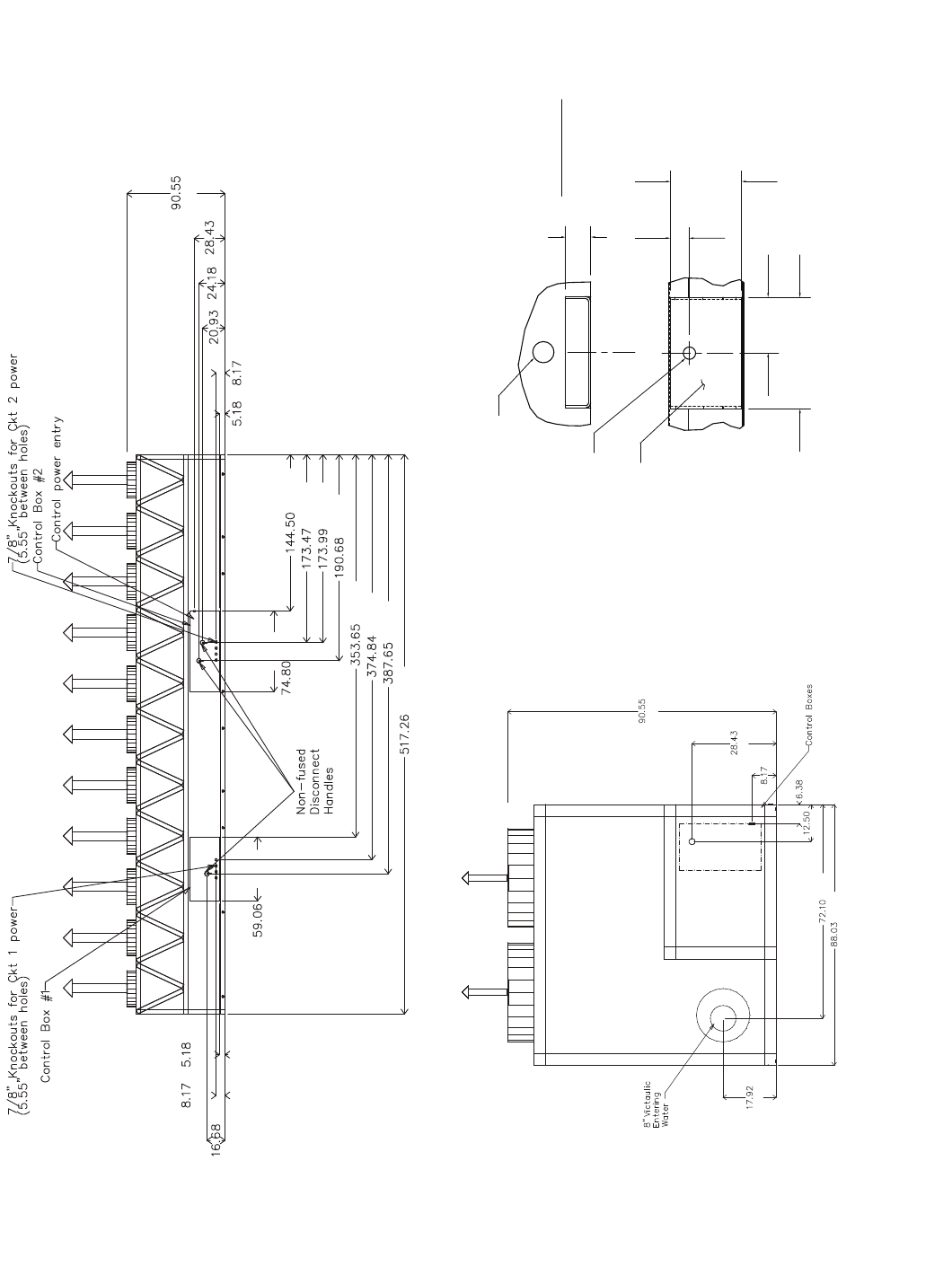
29
[2300]
[722]
[614]
[532]
[132] [208]
[1900] [3670]
[4406]
[4419]
[4843]
[8983]
[9521]
[9846]
[13138]
[1500]
[424]
[208] [132]
a30-4184
BACK VIEW
RIGHT END VIEW
3.93
7.88
[200]
DETAIL "A"
MOUNTING PLATE
CONTACT SURFACE
TYPICAL 4 PLACES
[100]
MOUNTING HOLE
0.875 DIA.[22.2]
MOUNTING
PLATE
1.50 DIA. [38.1]
RIGGING HOLE
[127]
5.0
[33]
1.31
1.75
[44]
[2300]
[722]
[208]
[162]
[317]
[1831]
[2236]
[455]
Fig. 14 — 30XA450,500 Air-Cooled Liquid Chiller with Dual Point Connections Dimensions (cont)
30
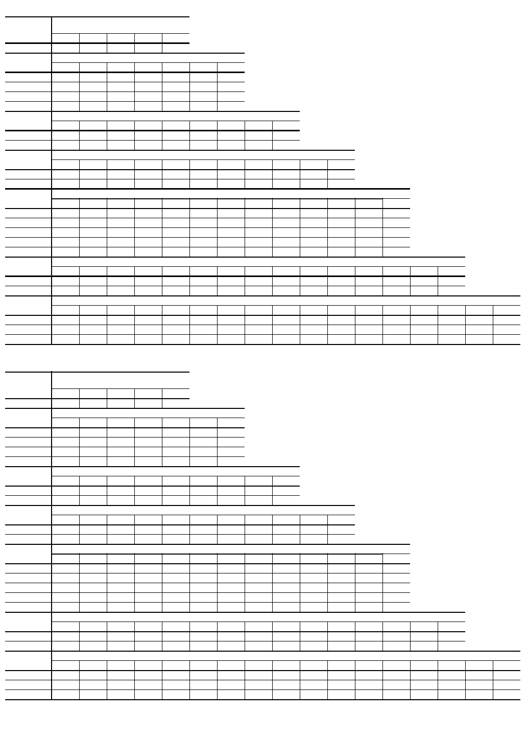
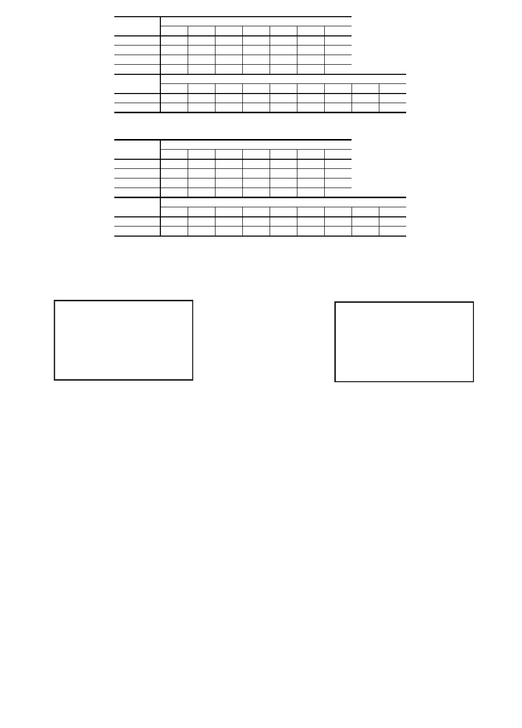
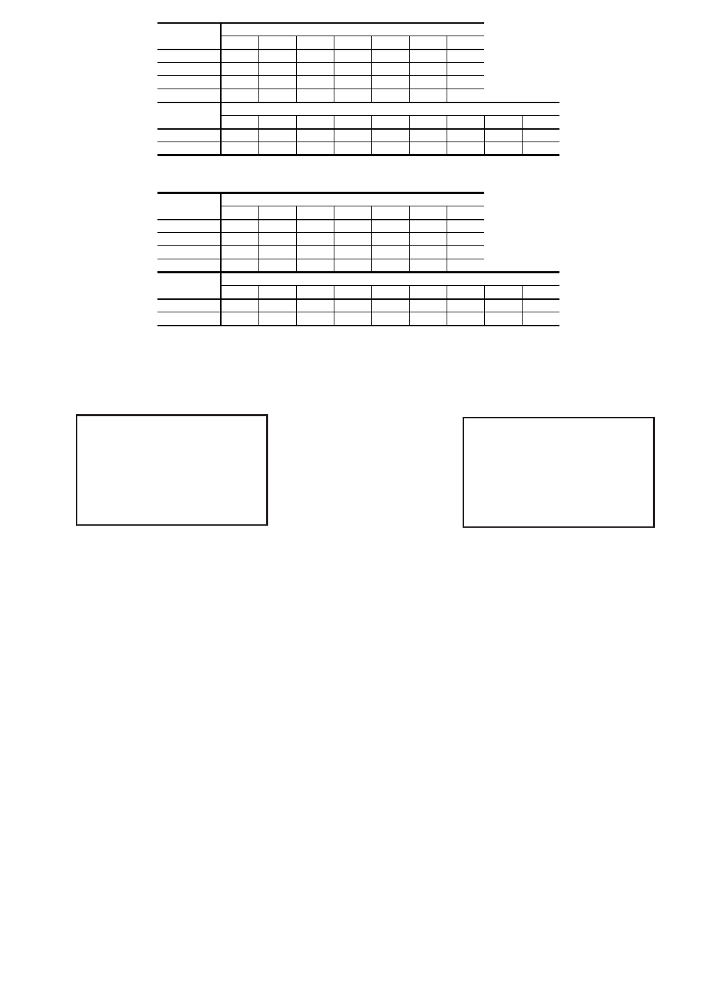
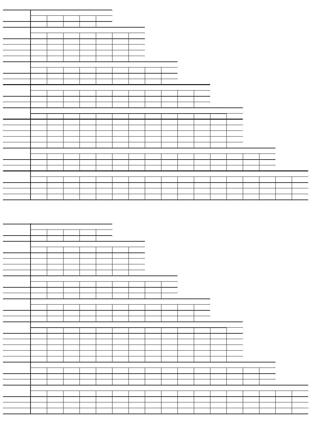
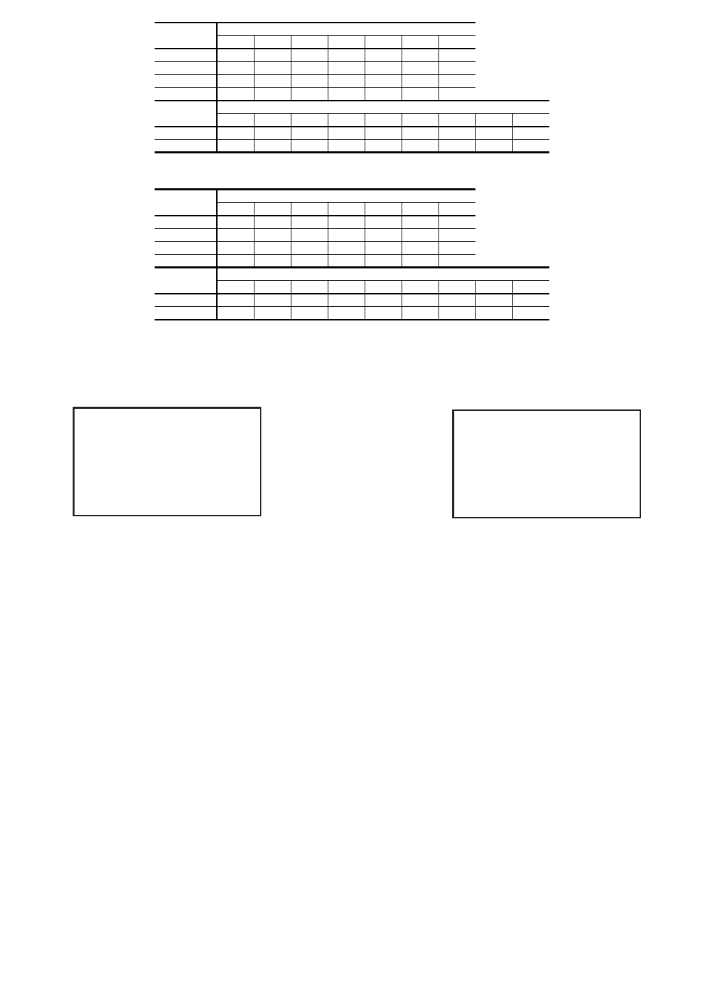
Fig. 15A — Unit Mounting Weights (Units with MCHX Condenser Coils)
UNITS WITHOUT PUMPS — ENGLISH
UNITS WITHOUT PUMPS — SI
30XA
UNIT SIZE
MOUNTING WEIGHT (lb)
MCHX CONDENSER COILS
ABCDTotal
080 1947 1673 1670 1943 7234
30XA
UNIT SIZE
MOUNTING WEIGHT (lb) MCHX CONDENSER COILS
ABCDEFTotal
090 1201 2043 750 951 1983 1199 8127
100 1226 209878098120381224 8348
110 1239 2136 7981006 2075 1229 8483
120 1272 2174 800 1007 2106 1263 8622
30XA
UNIT SIZE
MOUNTING WEIGHT (lb) MCHX CONDENSER COILS
ABCDEFGHTotal
140 1897 1444 864 1181 1217 8831584 1699 10,768
160 1949 1469 8781206 1246 899 1603 1750 11,000
30XA
UNIT SIZE
MOUNTING WEIGHT (lb) MCHX CONDENSER COILS
ABCDEFGH I JTotal
180 905 1484 1164 1849 1187 1224 1868840 1289888 12,699
200 909 1499 1188 1870 1192 1232 1879 8481299 893 12,810
30XA
UNIT SIZE
MOUNTING WEIGHT (lb) MCHX CONDENSER COILS
ABCDEFGH I JKLTotal
220 813 1196 1592 14988281216 1259 8481363 1064 1237 832 13,748
240 829 12181617 1520 830 12181261 850 1371 1073 1260 849 13,897
260 495 1431 1630 763 2465 1013 15282380800 1333 1386 495 15,720
280 497 1451 1663 771 2497 1015 1530 2390 803 13581406 497 15,878
300 502 1465 168678625681027 1557 2454 811 1367 1417 502 16,141
30XA
UNIT SIZE
MOUNTING WEIGHT (lb) MCHX CONDENSER COILS
ABCDEFGH I JKLMNTotal
325 742 742 9781531 783 2546 1067 1563 2334 804 1646 1247 742 742 17,467
350 745 745 982 1546 792 25981077 158923868081651 1249 745 745 17,659
30XA
UNIT SIZE
MOUNTING WEIGHT (lb) MCHX CONDENSER COILS
ABCDEFGH I JKLMNOPTotal
400 847 1234 1511 2965 1255 789 2214 1071 1566 2286 747 1265 2152 991 1277 86823,038
450 856 1179 2160 2282 905 1057 2030 2053 2711 1934 1551 1266 1440 13851216 876 24,901
500 843 1236 2207 2334 909 1060 2037 2060 27181941 1555 1269 1457 1401 1279 863 25,167
30XA
UNIT SIZE
MOUNTING WEIGHT (kg)
MCHX CONDENSER COILS
ABCDTotal
080 883 759 7588823281
30XA
UNIT SIZE
MOUNTING WEIGHT (kg) MCHX CONDENSER COILS
ABCDEFTotal
090 545 927 340 431 899 544 3686
100 556 952 354 445 924 555 3786
110 562 969 362 456 941 5583848
120 577 986 363 457 955 573 3911
30XA
UNIT SIZE
MOUNTING WEIGHT (kg) MCHX CONDENSER COILS
ABCDEFGHTotal
140 860 655 392 536 552 401 719 771 4884
160 884 666 398547 565 408727 794 4990
30XA
UNIT SIZE
MOUNTING WEIGHT (kg) MCHX CONDENSER COILS
ABCDEFGH I JTotal
180 410 673 528839 538555 847 381584 403 5760
200 412 680 539 848541 559 852 385589 405 5811
30XA
UNIT SIZE
MOUNTING WEIGHT (kg) MCHX CONDENSER COILS
ABCDEFGH I JKLTotal
220 369 542 722 680 376 552 571 385618483 561 3786236
240 376 552 734 690 377 553 572 386 622 487 572 3856304
260 225 649 740 346 1118460 693 1079 363 605 629 225 7130
280 225 658754 350 1133 461 694 1084 364 616 638225 7202
300 228664 765 357 1165 466 706 1113 368620 643 2287322
30XA
UNIT SIZE
MOUNTING WEIGHT (kg) MCHX CONDENSER COILS
ABCDEFGH I JKLMNTotal
325 337 337 444 695 355 1155 484 709 1058365 746 565 337 337 7923
350 338338446 701 359 1179 488 721 1082 367 749 567 3383388010
30XA
UNIT SIZE
MOUNTING WEIGHT (kg) MCHX CONDENSER COILS
ABCDEFGH I JKLMNOPTotal
400 384 560 685 1345 569 3581004 486 710 1037 339 574 976 450 579 394 10 450
450 388 535 980 1035 411 479 921 931 1230 877 704 574 653 628551 397 11 295
500 382 561 1001 1059 412 481 924 934 1233 880 705 576 661 635 580 391 11 416
31
AB
D
C
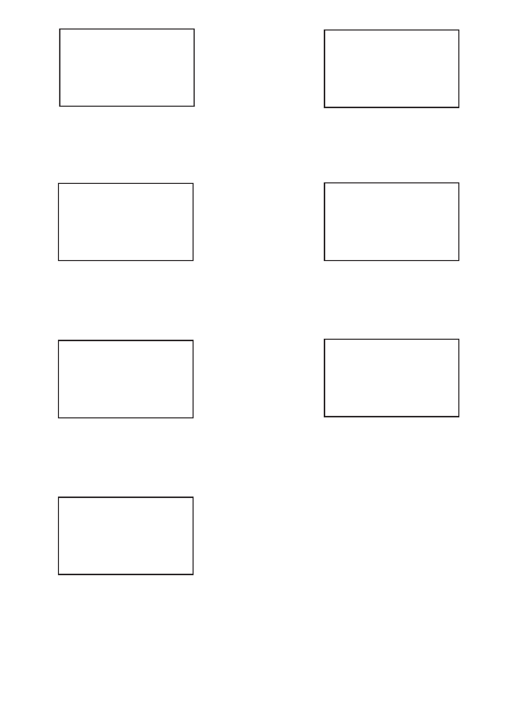
COOLER SIDE
COMPRESSOR SIDE
A
BC
F
E
D
COOLER SIDE
COMPRESSOR SIDE
ABCD
HGFE
COOLER SIDE
COMPRESSOR SIDE
ABCDE
GF
H
JI
COOLER SIDE
COMPRESSOR SIDE
ABCDE
F
LKJ
IHG
COOLER SIDE
COMPRESSOR SIDE
A
BCDEFG
NMLK
J
IH
COOLER SIDE
COMPRESSOR SIDE
ABCDEFGH
PONMLK
JI
COOLER SIDE
COMPRESSOR SIDE
30XA080
30XA090-120
30XA140,160
30XA180,200
30XA220-300
30XA325-350
30XA400-500
Fig. 15A — Unit Mounting Weights (Units with MCHX Condenser Coils) (cont)
LEGEND
MCHX — Microchannel Heat Exchanger
a30-4419
a30-4420
a30-4421
a30-4423
a30-4422
a30-4424
a30-4425
32
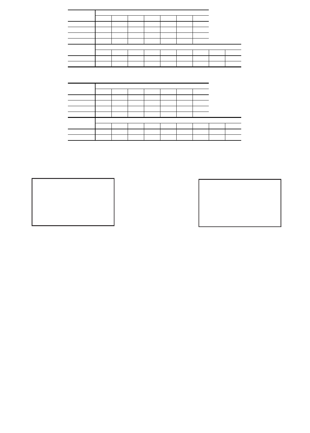
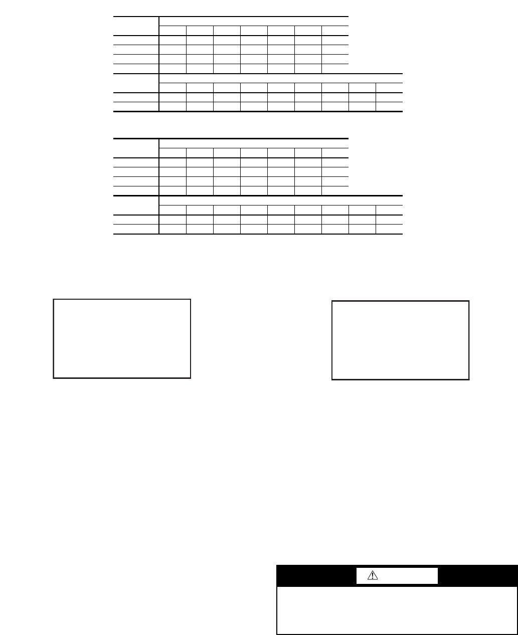
SINGLE PUMP UNITS — ENGLISH
SINGLE PUMP UNITS — SI
30XA
UNIT SIZE
MOUNTING WEIGHT (lb) MCHX CONDENSER COILS
ABCDEFTotal
090 1201 2754 1087 900 1944 1199 9085
100 1226 2814 1123 924 1995 1224 9306
110 1239 2855 1145 945 2027 1229 9441
120 1272 2893 1147 947 2059 1263 9580
30XA
UNIT SIZE
MOUNTING WEIGHT (lb) MCHX CONDENSER COILS
ABCDEFGHTotal
140 1897 1444 1609 1606 1078810 1584 1699 11,726
160 1949 1469 1626 1635 1103 824 1603 1750 11,958
30XA
UNIT SIZE
MOUNTING WEIGHT (kg) MCHX CONDENSER COILS
ABCDEFTotal
090 545 1249 493 408882 544 4121
100 556 1276 510 419 905 555 4221
110 562 1295 519 429 920 5584282
120 577 1312 520 430 934 573 4346
30XA
UNIT SIZE
MOUNTING WEIGHT (kg) MCHX CONDENSER COILS
ABCDEFGHTotal
140 860 655 730 728489 367 719 771 5319
160 884 666 737 742 500 374 727 794 5424
30XA090-120 30XA140,160
LEGEND
MCHX — Microchannel Heat Exchanger
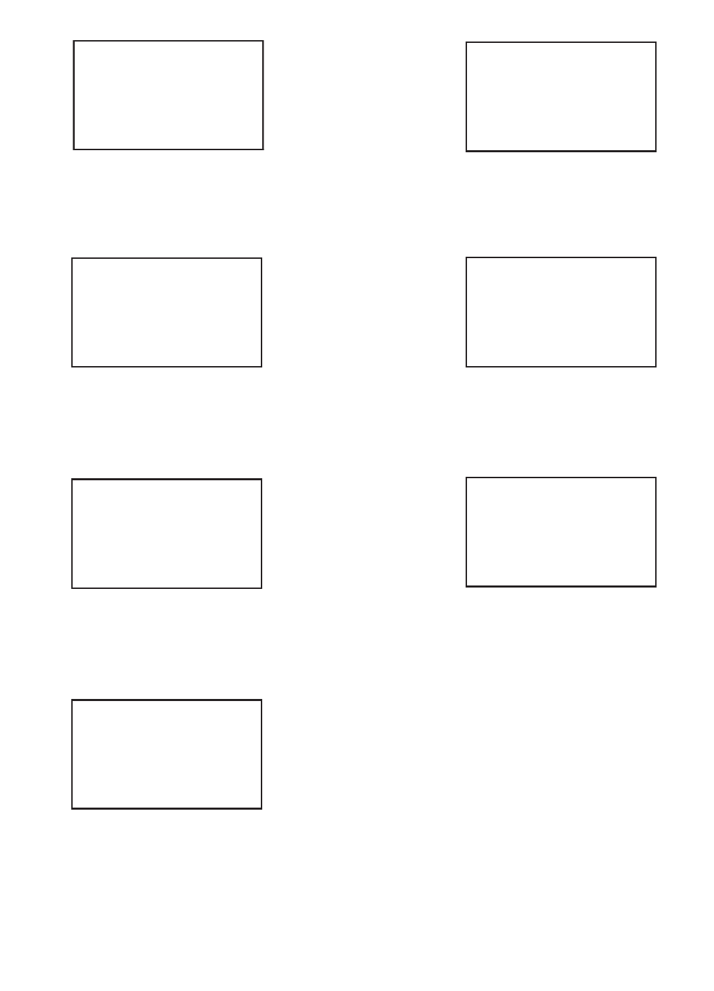
Fig. 15A — Unit Mounting Weights (Units with MCHX Condenser Coils) (cont)
a30-4420 a30-4421
A
BC
F
E
D
COOLER SIDE
COMPRESSOR SIDE
ABCD
HGFE
COOLER SIDE
COMPRESSOR SIDE
33
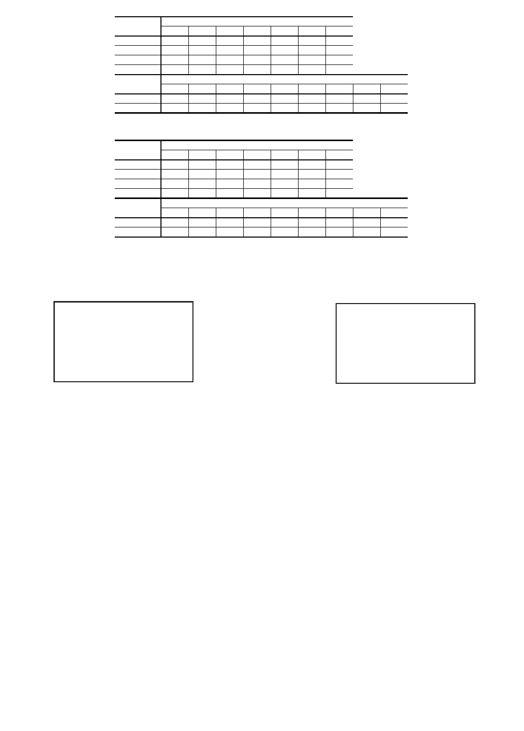
DUAL PUMP UNITS — ENGLISH
DUAL PUMP UNITS — SI
30XA
UNIT SIZE
MOUNTING WEIGHT (lb) MCHX CONDENSER COILS
ABCDEFTotal
090 1201 2962 1176 900 1944 1199 9382
100 1226 3022 1212 924 1995 1224 9603
110 1239 3064 1234 945 2027 1229 9738
120 1272 3101 1236 947 2059 1263 9877
30XA
UNIT SIZE
MOUNTING WEIGHT (lb) MCHX CONDENSER COILS
ABCDEFGHTotal
140 1897 1444 18181694 1078810 1584 1699 12,023
160 1949 1469 1834 1724 1103 824 1603 1750 12,255
30XA
UNIT SIZE
MOUNTING WEIGHT (kg) MCHX CONDENSER COILS
ABCDEFTotal
090 545 1343 533 408882 544 4255
100 556 1371 550 419 905 555 4356
110 562 1390 560 429 920 5584417
120 577 1407 560 430 934 573 4480
30XA
UNIT SIZE
MOUNTING WEIGHT (kg) MCHX CONDENSER COILS
ABCDEFGHTotal
140 860 655 825 769 489 367 719 771 5454
160 884 666 832 782 500 374 727 794 5559
30XA090-120 30XA140,160
LEGEND
MCHX — Microchannel Heat Exchanger
Fig. 15A — Unit Mounting Weights (Units with MCHX Condenser Coils) (cont)
a30-4420 a30-4421
A
BC
F
E
D
COOLER SIDE
COMPRESSOR SIDE
ABCD
HGFE
COOLER SIDE
COMPRESSOR SIDE

34
Fig. 15B — Unit Mounting Weights (Units with Al/Cu Condenser Coils)
UNITS WITHOUT PUMPS — ENGLISH
*Condenser Coil: Aluminum Fins/Copper Tubing.
UNITS WITHOUT PUMPS — SI
*Condenser Coil: Aluminum Fins/Copper Tubing.
30XA
UNIT SIZE
MOUNTING WEIGHT (lb) — Al/Cu*
ABCDTotal
080 2059 178517782051 7674
30XA
UNIT SIZE
MOUNTING WEIGHT (lb) — Al/Cu*
ABCDEFTotal
090 1273 2188 822 1023 2127 1271 8704
100 1299 2244 853 1054 2184 1297 8931
110 1312 2284872 1079 2222 1303 9071
120 1346 2322 874 1082 2255 1337 9216
30XA
UNIT SIZE
MOUNTING WEIGHT (lb) — Al/Cu*
ABCDEFGHTotal
140 2007 1554 9381254 1291 957 1695 1809 11,505
160 2061 1581 953 1281 1321 974 1715 1862 11,748
30XA
UNIT SIZE
MOUNTING WEIGHT (lb) — Al/Cu*
ABCDEFGH I JTotal
180 979 15581239 19981261 12982016 915 1363 962 13,590
200 984 1574 1263 2020 1267 13082029 923 1375 96813,712
30XA
UNIT SIZE
MOUNTING WEIGHT (lb) — Al/Cu*
ABCDEFGH I JKLTotal
220 883 1266 1697 1603 8981286 1329 91814681169 1307 902 14,727
240 900 1288 1723 1626 901 1289 1331 921 1477 1179 1331 920 14,887
260 566 1572 1701 834 2607 1084 1599 2521 871 1404 1528566 16,853
280 569 1594 1734 843 2640 1087 1601 2533 875 1429 1549 569 17,022
300 5781617 1762 862 2720 1103 1633 2607 887 1444 1570 57817,362
30XA
UNIT SIZE
MOUNTING WEIGHT (lb) — Al/Cu*
ABCDEFGH I JKLMNTotal
325 856 856 1054 1607 859 2697 1143 1639 2485880 1722 1322 856 856 18,834
350 860 860 1059 1623 869 2752 1153 1666 2539 885 1727 1326 860 860 19,040
30XA
UNIT SIZE
MOUNTING WEIGHT (lb) — Al/Cu*
ABCDEFGH I JKLMNOPTotal
400 924 1311 1588 3119 1332 866 236811481643 2440 824 1342 2306 1069 1354 945 24,578
450 933 1256 2276 2398982 1134 2184 2207 2866 2089 1629 1343 1556 1501 1293 953 26,600
500 921 1314 2325 2452 987 1139 2194 2217 2875 20981633 13481575 1519 1357 941 26,894
30XA
UNIT SIZE
MOUNTING WEIGHT (kg) — Al/Cu*
ABCDTotal
080 934 810 807 930 3481
30XA
UNIT SIZE
MOUNTING WEIGHT (kg) — Al/Cu*
ABCDEFTotal
090 578992 373 464 965 576 3948
100 5891018387478991 588 4051
110 595 1036 396 4891008591 4115
120 611 1053 397 491 1023 607 4181
30XA
UNIT SIZE
MOUNTING WEIGHT (kg) — Al/Cu*
ABCDEFGHTotal
140 910 705 425 569 585 434 769 821 5219
160 935 717 432 581 599 442 778845 5329
30XA
UNIT SIZE
MOUNTING WEIGHT (kg) — Al/Cu*
ABCDEFGH I JTotal
180 444 707 562 906 572 589 915 415 618436 6164
200 446 714 573 916 575 593 920 419 624 439 6220
30XA
UNIT SIZE
MOUNTING WEIGHT (kg) — Al/Cu*
ABCDEFGH I JKLTotal
220 401 574 770 727 407 583 603 416 666 530 593 409 6680
240 4085847
82738409 585 604 418670 535 604 417 6753
260 257 713 772 3781182 492 725 1144 395 637 693 257 7644
280 258723 787382 1197 493 726 1149 397 648703 2587721
300 262 734 799 391 1234 501 741 1182 402 655 712 262 7876
30XA
UNIT SIZE
MOUNTING WEIGHT (kg) — Al/Cu*
ABCDEFGH I JKLMNTotal
325 388 388 478729 390 1224 518744 1127 399 781 600 388 388 8543
350 390 390 480 736 394 1248523 756 1152 401 784 601 390 390 8636
30XA
UNIT SIZE
MOUNTING WEIGHT (kg) — Al/Cu*
ABCDEFGH I JKLMNOPTotal
400 419 595 720 1415 604 393 1074 521 745 1107 374 609 1046 485 614 42811 149
450 423 570 1032 1088 446 514 991 1001 1300 948739 609 706 681586 432 12 066
500 418596 1055 1112 448516 995 1005 1304 952 741 611 714 689 616 427 12 199

35
AB
D
C
COOLER SIDE
COMPRESSOR SIDE
A
BC
F
E
D
COOLER SIDE
COMPRESSOR SIDE
ABCD
HGFE
COOLER SIDE
COMPRESSOR SIDE
ABCDE
GF
H
JI
COOLER SIDE
COMPRESSOR SIDE
ABCDE
F
LKJ
IHG
COOLER SIDE
COMPRESSOR SIDE
A
BCDEFG
NMLK
J
IH
COOLER SIDE
COMPRESSOR SIDE
ABCDEFGH
PONMLK
JI
COOLER SIDE
COMPRESSOR SIDE
30XA080
30XA090-120
30XA140,160
30XA180,200
30XA220-300
30XA325-350
30XA400-500
Fig. 15B — Unit Mounting Weights (Units with Al/Cu Condenser Coils) (cont)
a30-4419
a30-4420
a30-4421
a30-4423
a30-4422
a30-4424
a30-4425
36
SINGLE PUMP UNITS — ENGLISH
SINGLE PUMP UNITS — SI
*Condenser Coil: Aluminum Fins/Copper Tubing.
30XA
UNIT SIZE
MOUNTING WEIGHT (lb) — Al/Cu*
ABCDEFTotal
090 1273 28981160 972 2089 1271 9,662
100 1299 2959 1196 997 2140 1297 9,889
110 1312 3002 1219 1019 2175 1303 10,029
120 1346 3041 1221 1021 22081337 10,174
30XA
UNIT SIZE
MOUNTING WEIGHT (lb) — Al/Cu*
ABCDEFGHTotal
140 2007 1554 1683 1679 1152 88316951809 12,463
160 2061 1581 1701 1710 11788981715 1862 12,706
30XA
UNIT SIZE
MOUNTING WEIGHT (kg) — Al/Cu*
ABCDEFTotal
090 5781314 526 441 947 576 4383
100 589 1342 543 452 971 588 4485
110 595 1362 553 462 986 591 4549
120 611 1379 554 463 1001 607 4615
30XA
UNIT SIZE
MOUNTING WEIGHT (kg) — Al/Cu*
ABCDEFGHTotal
140 910 705 763 762 523 401 769 821 5653
160 935 717 771 776 534 408778845 5763
30XA090-120 30XA140,160
Fig. 15B — Unit Mounting Weights (Units with Al/Cu Condenser Coils) (cont)
a30-4420 a30-4421
A
BC
F
E
D
COOLER SIDE
COMPRESSOR SIDE
ABCD
HGFE
COOLER SIDE
COMPRESSOR SIDE
37
DUAL PUMP UNITS — ENGLISH
DUAL PUMP UNITS — SI
*Condenser Coil: Aluminum Fins/Copper Tubing.
30XA
UNIT SIZE
MOUNTING WEIGHT (lb) — Al/Cu*
ABCDEFTotal
090 1273 3106 1248972 2089 1271 9,959
100 1299 31681285 997 2140 1297 10,186
110 1312 3211 1307 1019 2175 1303 10,326
120 1346 3249 1310 1021 22081337 10,471
30XA
UNIT SIZE
MOUNTING WEIGHT (lb) — Al/Cu*
ABCDEFGHTotal
140 2007 1554 1891 17681152 88316951809 12,760
160 2061 1581 1909 1799 11788981715 1862 13,003
30XA
UNIT SIZE
MOUNTING WEIGHT (kg) — Al/Cu*
ABCDEFTotal
090 5781409 566 441 947 576 4517
100 589 1437 583 452 971 588 4620
110 595 1456 593 462 986 591 4684
120 611 1474 594 463 1001 607 4750
30XA
UNIT SIZE
MOUNTING WEIGHT (kg) — Al/Cu*
ABCDEFGHTotal
140 910 705 858802 523 401 769 821 5788
160 935 717 866 816 534 408778845 5898
30XA090-120 30XA140,160
Fig. 15B — Unit Mounting Weights (Units with Al/Cu Condenser Coils) (cont)
a30-4420 a30-4421
A
BC
F
E
D
COOLER SIDE
COMPRESSOR SIDE
ABCD
HGFE
COOLER SIDE
COMPRESSOR SIDE
38
Fig. 15C — Unit Mounting Weights (Units with Cu/CU Condenser Coils)
UNITS WITHOUT PUMPS — ENGLISH
*Condenser Coil: Copper Fins/Copper Tubing.
UNITS WITHOUT PUMPS — SI
*Condenser Coil: Copper Fins/Copper Tubing.
30XA
UNIT SIZE
MOUNTING WEIGHT (lb) — Cu/Cu*
ABCDTotal
080 2244 1970 1956 22288398
30XA
UNIT SIZE
MOUNTING WEIGHT (lb) — Cu/Cu*
ABCDEFTotal
090 1394 2429 943 1144 23681392 9,669
100 1420 2485 974 1174 2425 14189,896
110 1433 2525 993 1200 2463 1424 10,036
120 1467 2563 995 1202 2496 145810,181
30XA
UNIT SIZE
MOUNTING WEIGHT (lb) — Cu/Cu*
ABCDEFGHTotal
140 2188 1735 10581375 1411 10781876 1990 12,711
160 2242 1762 1074 1401 1442 1095 1896 2043 12,954
30XA
UNIT SIZE
MOUNTING WEIGHT (lb) — Cu/Cu*
ABCDEFGH I JTotal
180 1099 1679 1359 2239 1382 1419 22581035 14831083 15,037
200 1105 1695 1384 2261 1388 14282271 1044 1495 1089 15,159
30XA
UNIT SIZE
MOUNTING WEIGHT (lb) — Cu/Cu*
ABCDEFGH I JKLTotal
220 995 13781865 1771 1010 13981441 1030 1636 1337 1419 1014 16,295
240 1012 1400 1891 1794 1013 1401 1443 1033 1645 1347 1443 1032 16,455
260 679 17981814 947 2833 1197 1712 2748984 1517 1754 679 18,662
280 6821820 1847 956 2866 1200 1715 2759 988 1542 1775 68218,831
300 699 18581883983 2962 1224 1754 284810081564 1811 699 19,292
30XA
UNIT SIZE
MOUNTING WEIGHT (lb) — Cu/Cu*
ABCDEFGH I JKLMNTotal
325 1037 1037 1175 1728980 2939 1263 1760 2727 1001 1842 1443 1037 1037 21,005
350 1041 1041 1180 1743 990 2993 1274 17862780100618481447 1041 1041 21,211
30XA
UNIT SIZE
MOUNTING WEIGHT (lb) —Cu/Cu*
ABCDEFGH I JKLMNOPTotal
400 1045 1432 17083361 1453 987 2609 1269 1764 2681 945 1462 2547 1189 1474 1065 26,990
450 1054 1377 2457 2579 1103 1255 2426 2449 3107 2330 1749 1464 17381682 1413 1073 29,254
500 1041 1434 2506 2633 11081259 2435 24583116 2340 1754 14681756 1700 1477 1061 29,547
30XA
UNIT SIZE
MOUNTING WEIGHT (kg) — Cu/Cu*
ABCDTotal
080 1018893 887 1011 3809
30XA
UNIT SIZE
MOUNTING WEIGHT (kg) — Cu/Cu*
ABCDEFTotal
090 632 1102 428519 1074 631 4386
100 644 1127 442 533 1100 643 4489
110 650 1145 450 544 1117 646 4552
120 665 1163 451 545 1132 661 4618
30XA
UNIT SIZE
MOUNTING WEIGHT (kg) — Cu/Cu*
ABCDEFGHTotal
140 992 787480 624 640 489851 903 5766
160 1017 799 487 636 654 497 860 927 5876
30XA
UNIT SIZE
MOUNTING WEIGHT (kg) — Cu/Cu*
ABCDEFGH I JTotal
180 499 762 617 1016 627 644 1024 470 673 491 6821
200 501 769 6281026 630 6481030 474 678494 6876
30XA
UNIT SIZE
MOUNTING WEIGHT (kg) — Cu/Cu*
ABCDEFGH I JKLTotal
220 451 625 846 804 458634 653 467 742 607 644 460 7391
240 459 635 858814 460 635 655 469 746 611 654 4687464
260 308816 823 429 1285 543 777 1246 446 688 796 3088465
280 309 826 838434 1300 544 7781252 448700 805 309 8542
300 317 843 854 446 1343 555 796 1292 457 710 821 317 8751
30XA
UNIT SIZE
MOUNTING WEIGHT (kg) — Cu/Cu*
ABCDEFGH I JKLMNTotal
325 470 470 533 784 445 1333 573 7981237 454 836 655 470 470 9528
350 472 472 535 791 449 1358578810 1261 456 838656 472 472 9621
30XA
UNIT SIZE
MOUNTING WEIGHT (kg) — Cu/Cu*
ABCDEFGH I JKLMNOPTotal
400 474 649 775 1524 659 447 1183 576 800 1216 428663 1155 539 669 483 12 243
450 478624 1114 1170 500 569 1100 1111 1409 1057 793 664 788 763 641 487 13 269
500 472 651 1137 1194 502 571 1105 1115 1413 1061 796 666 797 771 670 481 13 402
39
AB
D
C
COOLER SIDE
COMPRESSOR SIDE
A
BC
F
E
D
COOLER SIDE
COMPRESSOR SIDE
ABCD
HGFE
COOLER SIDE
COMPRESSOR SIDE
ABCDE
GF
H
JI
COOLER SIDE
COMPRESSOR SIDE
ABCDE
F
LKJ
IHG
COOLER SIDE
COMPRESSOR SIDE
A
BCDEFG
NMLK
J
IH
COOLER SIDE
COMPRESSOR SIDE
ABCDEFGH
PONMLK
JI
COOLER SIDE
COMPRESSOR SIDE
30XA080
30XA090-120
30XA140,160
30XA180,200
30XA220-300
30XA325-350
30XA400-500
Fig. 15C — Unit Mounting Weights (Units with Cu/Cu Condenser Coils) (cont)
30-4419
30-4420
30-4421
a30-4423
30-4422
a30-4424
a30-4425
40
SINGLE PUMP UNITS — ENGLISH
SINGLE PUMP UNITS — SI
*Condenser Coil: Copper Fins/Copper Tubing.
30XA
UNIT SIZE
MOUNTING WEIGHT (lb) — Cu/Cu*
ABCDEFTotal
090 1394 3139 1280 1093 2330 1392 10,627
100 1420 3201 1317 1117 2382141810,854
110 1433 3244 1339 1139 2416 1424 10,994
120 1467 3282 1342 1142 2449 145811,139
30XA
UNIT SIZE
MOUNTING WEIGHT (lb) — Cu/Cu*
ABCDEFGHTotal
140 2188 1735 1804 1800 1273 1004 1876 1990 13,669
160 2242 1762 1821 1831 1299 1019 1896 2043 13,912
30XA
UNIT SIZE
MOUNTING WEIGHT (kg) — Cu/Cu*
ABCDEFTotal
090 632 1424 581 496 1057 631 4820
100 644 1452 597 507 1080 643 4923
110 650 1471 607 517 1096 646 4987
120 665 1489 609 5181111 661 5053
30XA
UNIT SIZE
MOUNTING WEIGHT (kg) — Cu/Cu*
ABCDEFGHTotal
140 992 787818816 577 455 851 903 6200
160 1017 799 826 830 589 462 860 927 6310
30XA090-120 30XA140,160
Fig. 15C — Unit Mounting Weights (Units with Cu/Cu Condenser Coils) (cont)
a30-4420 a30-4421
A
BC
F
E
D
COOLER SIDE
COMPRESSOR SIDE
ABCD
HGFE
COOLER SIDE
COMPRESSOR SIDE
41
RIGGING UNIT (See Fig. 16-18) — The 30XA080-500 units
are designed for overhead rigging and it is important that this
method be used. Holes are provided in frame base channels,
marked for rigging (see rigging label on unit). Field-supplied
shackles are required to facilitate lifting. Secure the shackles
to the base rails at the points noted on the rigging label. See
Table 2 for the number of lifting points for each unit.
Do not use a forklift truck to move the units.
Use spreader bars to keep cables or chains clear of unit sides.
As further protection plywood sheets may be placed against
sides of unit, behind cables or chains. Run cables or chains to a
central suspension point so that angle from horizontal is not less
than 45 degrees. Raise and set unit down carefully.
See Fig. 16-18 for rigging centers of gravity.
For shipping, some domestic units and all export units are
mounted on a wooden skid under entire base of unit. Skid can
be removed before unit is moved to installation site. Lift the
unit from above to remove skid. See Fig. 16-18 for rigging
center of gravity. On export units, the top skid can be used as
the spreader bars. If the unit was shipped with a shipping bag,
the bag must be removed to gain access to the rigging holes in
the base rail.
If overhead rigging is not available, the unit can be moved
on rollers or dragged. When unit is moved on rollers, the unit
skid, if equipped, must be removed. To lift the unit, use jacks at
the rigging points. Use a minimum number of rollers to distrib-
ute the load such that the rollers are no more than 6 ft (1.8 m)
apart. If the unit is to be dragged, lift the unit as described
above, and place unit on a pad. Apply moving force to the pad,
and not the unit. When in its final location, raise the unit and
remove the pad. If the unit was shipped with coil protection, it
must be removed before start-up. The shipping bag for export
units must be removed before start-up.
Step 3 — Cooler Fluid and Drain Piping Con-
nections — See Fig. 19-22 for piping applications.
GENERAL — The factory-installed victaulic connections al-
low clamp-on connection of water lines to the coolers in all
30XA units. A flow sensor is factory-installed in the side of the
entering fluid nozzle. See Fig. 23. See Table 3 for 30XA unit
operating range. See Fig. 20 for cooler option dimensions.
DUAL PUMP UNITS — ENGLISH
DUAL PUMP UNITS — SI
*Condenser Coil: Copper Fins/Copper Tubing.
30XA
UNIT SIZE
MOUNTING WEIGHT (lb) — Cu/Cu*
ABCDEFTotal
090 1394 3347 1369 1093 2330 1392 10,924
100 1420 3409 1406 1117 2382141811,151
110 1433 3452 14281139 2416 1424 11,291
120 1467 3491 1430 1142 2449 145811,436
30XA
UNIT SIZE
MOUNTING WEIGHT (lb) — Cu/Cu*
ABCDEFGHTotal
140 2188 1735 2012 1889 1273 1004 1876 1990 13,966
160 2242 1762 2029 1919 1299 1019 1896 2043 14,209
30XA
UNIT SIZE
MOUNTING WEIGHT (kg) — Cu/Cu*
ABCDEFTotal
090 632 1518621 496 1057 631 4955
100 644 1546 638507 1080 643 5058
110 650 1566 648517 1096 646 5122
120 665 1583 649 5181111 661 5187
30XA
UNIT SIZE
MOUNTING WEIGHT (kg) — Cu/Cu*
ABCDEFGHTotal
140 992 787 913 857 577 455 851 903 6335
160 1017 799 921 871 589 462 860 927 6445
30XA090-120 30XA140,160
Fig. 15C — Unit Mounting Weights (Units with Cu/Cu Condenser Coils) (cont)
a30-4420 a30-4421
A
BC
F
E
D
COOLER SIDE
COMPRESSOR SIDE
ABCD
HGFE
COOLER SIDE
COMPRESSOR SIDE
CAUTION
Remove the chilled water flow switch, entering and leaving
water thermistors before welding connecting piping. Rein-
stall flow switch and thermistors after welding is complete.
Failure to remove these devices may cause unit damage.
42
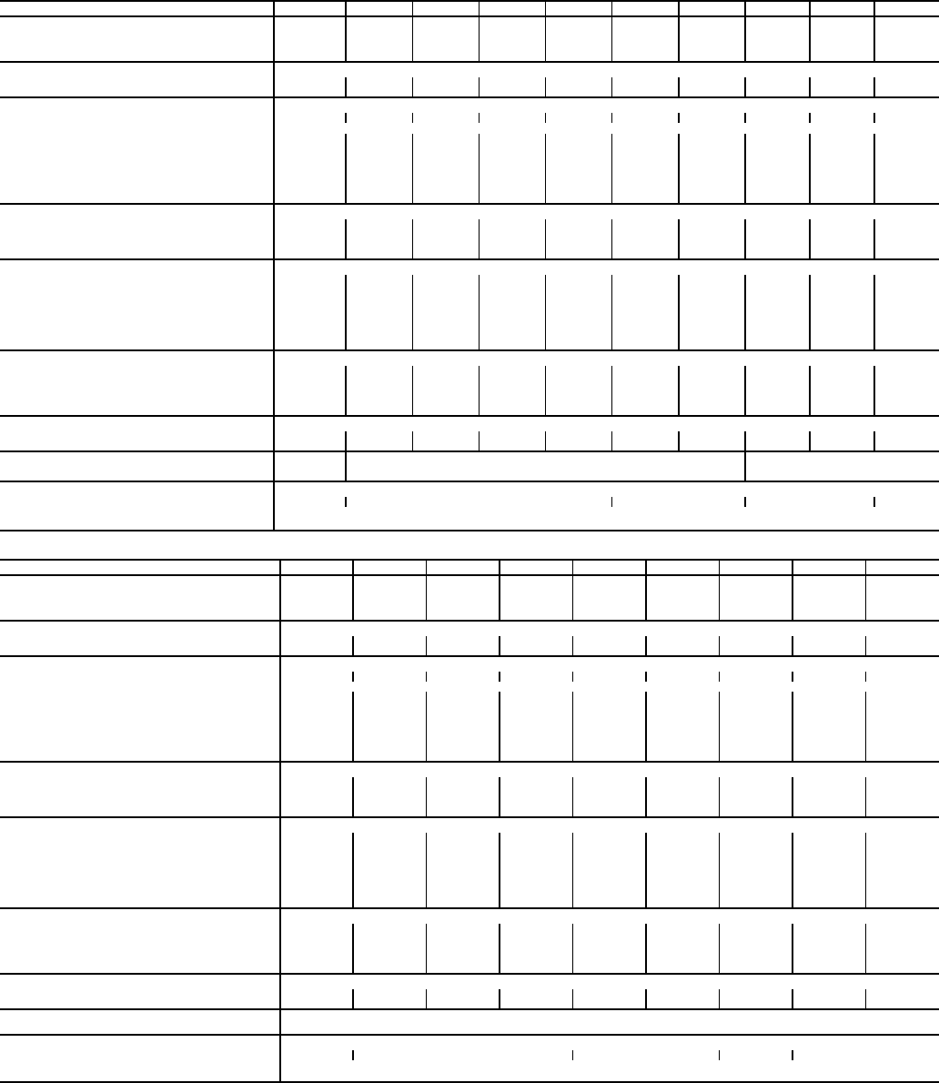
Table 1A — Physical Data, 30XA080-500 — English
LEGEND *Operating weight includes 2 pumps on models 30XA090-160. No pumps are available on
30XA080 or 30XA180-500. All weights include coil trim panels. See Fig. 15A and 15B for mount-
ing weights for units without pumps and units with single pump packages.
†30XA080 unit does not have an economizer.
**The high ambient temperature option is not available on 30XA080-120 units.
UNIT 30XA 080 090 100 110 120 140 160 180 200 220
OPERATING WEIGHT (lb)*
Al-Cu Condenser Coils 7,674 9,959 10,186 10,326 10,471 12,760 13,003 13,590 13,712 14,727
Cu-Cu Condenser Coils 8,39810,924 11,151 11,291 11,436 13,966 14,209 15,037 15,159 16,295
MCHX Condenser Coils 7,234 9,382 9,603 9,7389,877 12,023 12,255 12,699 12,810 13,748
REFRIGERANT TYPE R-134a, EXV Controlled System
Refrigerant Charge (lb) Ckt A/Ckt B/Ckt C 110/110/— 110/110/— 120/120/— 135/120/— 135/135/— 202/121/— 225/159/— 205/205/— 225/225/— 270/225/—
Refrigerant Charge (lb) Ckt A/Ckt B/Ckt C (MCHX) 98/98/— 94/94/— 96/96/— 100/96/— 100/100/— 137/96/— 135/100/— 141/141/— 161/161/— 170/161/—
COMPRESSORS Semi-Hermetic Twin Rotary Screws
Quantity 2 222222222
Speed (rpm) 3500
(Qty) Compressor Model Number Ckt A (1) 06TS-137† (1) 06TS-137 (1) 06TS-155 (1) 06TS-186 (1) 06TS-186 (1) 06TT-266 (1) 06TT-301 (1) 06TT-266 (1) 06TT-301 (1) 06TT-356
(Qty) Compressor Model Number Ckt B (1) 06TS-137† (1) 06TS-137 (1) 06TS-155 (1) 06TS-155 (1) 06TS-186 (1) 06TS-155 (1) 06TS-186 (1) 06TT-266 (1) 06TT-301 (1) 06TT-301
(Qty) Compressor Model Number Ckt C N/A N/A N/A N/A N/A N/A N/A N/A N/A N/A
Oil Charge (gal), Ckt A/Ckt B/Ckt C 5.5/5.5/— 5.5/5.5/— 5.5/5.5/— 5.5/5.5/— 5.5/5.5/— 6.25/5.5/— 6.25/5.5/— 6.25/6.25/— 6.25/6.25/— 6.75/6.25/—
Minimum Capacity Step (%)
Standard 15 15 15 14 15 11 11 15 15 14
Optional 999810 7 810 10 10
COOLER Flooded, Shell and Tube Type
Net Fluid Volume (gal.) 16.5 18.5 18.5 20.0 23.0 25.5 27.5 31.5 34.0 37.0
Maximum Refrigerant Pressure (psig) 220 220 220 220 220 220 220 220 220 220
Maximum Water Side Pressure without Pumps (psig) 300 300 300 300 300 300 300 300 300 300
Maximum Water Side Pressure with Pumps (psig) — 150 150 150 150 150 150 — — —
WATER CONNECTIONS
Drain (NPT, in.) 3/83/83/83/83/83/83/83/83/83/8
Standard, Inlet and Outlet, Victaulic (in.) 5 555555666
Number of Passes 2 222222222
Minus 1 Pass, Inlet and Outlet, Victaulic (in.) 5 555555888
Number of Passes 1 111111111
Plus 1 Pass, Inlet and Outlet, Victaulic (in.) 4 444455666
Number of Passes 3 333333333
CONDENSER FANS Shrouded Axial Type, Vertical Discharge
Fan Speed (rpm) Standard/High Ambient** 850/— 850/— 850/— 850/— 850/— 850/1140 850/1140 850/1140 850/1140 850/1140
No. Blades...Diameter (in.) 9...30 9...30 9...30 9...30 9...30 9...30 9...30 9...30 9...30 9...30
No. Fans (Ckt A/Ckt B/Ckt C) 3/3/— 4/4/— 4/4/— 4/4/— 4/4/— 6/4/— 6/4/— 6/6/— 6/6/— 7/6/—
Total Airflow (cfm) 850 rpm 55,800 74,400 74,400 74,400 74,400 93,000 93,000 111,600 111,600 120,900
Total Airflow (cfm) 1140 rpm — — — — — 124,000 124,000 148,800 148,800 161,200
CONDENSER COILS
No. Coils (Ckt A/Ckt B/Ckt C) 3/3/— 4/4/— 4/4/— 4/4/— 4/4/— 6/4/— 6/4/— 6/6/— 6/6/— 7/6/—
Total Face Area (sq ft) 141 188 188 188 188 234 234 281281 305
HYDRONIC MODULE (Optional)
Pump N/A Pump(s) with pressure/temperature taps and combination valve.
Single or Dual, 3600 rpm
N/A
CHASSIS DIMENSIONS (ft-in.)
Length 11-10 15-9 19-823-7 27-6
Width 7-43/4
Height 7-67/16
UNIT 30XA 240 260 280 300 325 350 400 450 500
OPERATING WEIGHT (lb)*
Al-Cu Condenser Coils 14,887 16,853 17,022 17,362 18,834 19,040 24,57826,600 26,894
Cu-Cu Condenser Coils 16,455 18,662 18,831 19,292 21,005 21,211 26,990 29,254 29,547
MCHX Condenser Coils 13,897 15,720 15,87816,141 17,467 17,659 23,03824,901 25,167
REFRIGERANT TYPE R-134a, EXV Controlled System
Refrigerant Charge (lb) Ckt A/Ckt B/Ckt C 270/270/— 375/220/— 375/270/— 415/270/— 375/375/— 415/375/— 270/270/375 415/205/415 415/270/415
Refrigerant Charge (lb) Ckt A/Ckt B/Ckt C (MCHX) 170/168/— 247/165/— 240/170/— 245/170/— 240/240/— 245/240/— 170/170/215 236/170/227 243/177/227
COMPRESSORS Semi-Hermetic Twin Rotary Screws
Quantity 222222333
Speed (rpm) 3500
(Qty) Compressor Model Number Ckt A (1) 06TT-356 (1) 06TU-483 (1) 06TU-483 (1) 06TU-554 (1) 06TU-483 (1) 06TU-554 (1) 06TT-356 (1) 06TU-554 (1) 06TU-554
(Qty) Compressor Model Number Ckt B (1) 06TT-356 (1) 06TT-301 (1) 06TT-356 (1) 06TT-356 (1) 06TU-483 (1) 06TU-483 (1) 06TT-356 (1) 06TT-266 (1) 06TT-356
(Qty) Compressor Model Number Ckt C N/A N/A N/A N/A N/A N/A (1) 06TU-483 (1) 06TU-554 (1) 06TU-554
Oil Charge (gal), Ckt A/Ckt B/Ckt C 6.75/6.75/— 7.5/6.75/— 7.5/6.75/— 7.5/6.75/— 7.5/7.5/— 7.5/7.5/— 6.75/6.75/7.5 7.5/6.25/7.5 7.5/6.75/7.5
Minimum Capacity Step (%)
Standard 15 11 13 12 15 15 9 6 7
Optional 10 8971010645
COOLER Flooded, Shell and Tube Type
Net Fluid Volume (gal.) 39.0 42.0 44.0 48.5 50.5 53.4 68.0 75.0 83.0
Maximum Refrigerant Pressure (psig) 220 220 220 220 220 220 220 220 220
Maximum Water Side Pressure without Pumps (psig) 300 300 300 300 300 300 300 300 300
Maximum Water Side Pressure with Pumps (psig) —————————
WATER CONNECTIONS
Drain (NPT, in.) 3/83/83/83/83/83/83/83/83/8
Standard, Inlet and Outlet, Victaulic (in.) 688888888
Number of Passes 222222111
Minus 1 Pass, Inlet and Outlet, Victaulic (in.) 888888———
Number of Passes 111111———
Plus 1 Pass, Inlet and Outlet, Victaulic (in.) 688888———
Number of Passes 333333———
CONDENSER FANS Shrouded Axial Type, Vertical Discharge
Fan Speed (rpm) Standard/High Ambient** 850/1140 850/1140 850/1140 850/1140 850/1140 850/1140 850/1140 850/1140 850/1140
No. Blades...Diameter (in.) 9...30 9...30 9...30 9...30 9...30 9...30 9...30 9...30 9...30
No. Fans (Ckt A/Ckt B/Ckt C) 7/6/— 9/6/— 9/7/— 10/6/— 9/9/— 9/9/— 6/6/88/6/88/6/8
Total Airflow (cfm) 850 rpm 120,900 139,500 148,800 148,800 167,400 167,400 186,000 204,600 204,600
Total Airflow (cfm) 1140 rpm 161,200 186,000 198,400 198,400 223,200 223,200 248,000 272,800 272,800
CONDENSER COILS
No. Coils (Ckt A/Ckt B/Ckt C) 7/6/— 9/6/— 9/7/— 10/6/— 9/9/— 9/9/— 6/6/88/6/88/6/8
Total Face Area (sq ft) 305 352 375 375 422 422 469 516 516
HYDRONIC MODULE (Optional)
Pump N/A
CHASSIS DIMENSIONS (ft-in.)
Length 27-6 31-5 35-4 39-3 43-2
Width 7-43/4
Height 7-67/16
Cu — Copper
Al — Aluminum
EXV — Electronic Expansion Valve
MCHX — Microchannel Heat Exchanger
N/A — Not Applicable
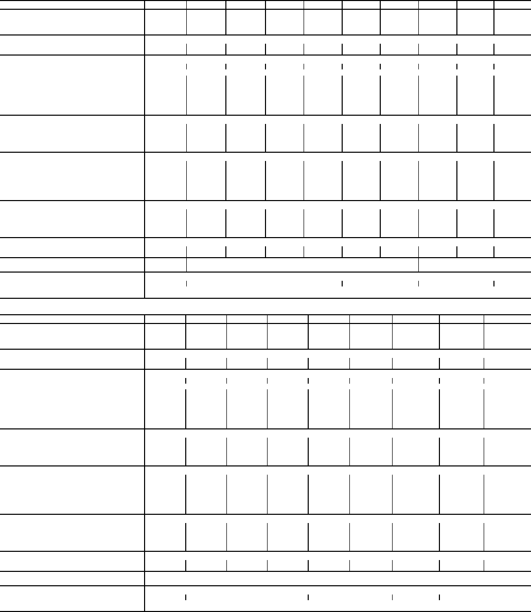
43
Table 1B — Physical Data, 30XA080-500 — SI
LEGEND *Operating weight includes 2 pumps on models 30XA090-160. No pumps are available on
30XA080 or 30XA180-500. All weights include coil trim panels. See Fig. 15A and 15B for mount-
ing weights for units without pumps and units with single pump packages.
†30XA080 unit does not have an economizer.
**The high ambient temperature option is not available on 30XA080-120 units.
UNIT 30XA 080 090 100 110 120 140 160 180 200 220
OPERATING WEIGHT (kg)*
Al-Cu Condenser Coils 3 481 4 517 4 620 4 684 4 750 5 788 5 8986 164 6 220 6 680
Cu-Cu Condenser Coils 3 809 4 955 5 0585 122 5 187 6 335 6 445 6 821 6 876 7 391
MCHX Condenser Coils 3 281 4 255 4 356 4 417 4 480 5 454 5 559 5 760 5 811 6 236
REFRIGERANT TYPE R-134a, EXV Controlled System
Refrigerant Charge (kg) Ckt A/Ckt B/Ckt C 50/50/— 50/50/— 54/54/— 61/61/— 61/61/— 92/55/— 102/72/— 93/93/— 102/102— 112/102/—
Refrigerant Charge (kg) Ckt A/Ckt B/Ckt C (MCHX) 44.5/44.5/— 42.6/42.6/— 43.6/43.6/— 45.4/45.4/— 43.4/43.4/— 62.1/43.6/— 62.1/45.3/— 64.0/64.0/— 73.0/73.0/— 77.1/73.0/—
COMPRESSORS Semi-Hermetic Twin Rotary Screws
Quantity 2 2 2 2222222
Speed (r/s) 58.3
(Qty) Compressor Model Number Ckt A (1) 06TS-137† (1) 06TS-137 (1) 06TS-155 (1) 06TS-186 (1) 06TS-186 (1) 06TT-266 (1) 06TT-301 (1) 06TT-266 (1) 06TT-301 (1) 06TT-356
(Qty) Compressor Model Number Ckt B (1) 06TS-137† (1) 06TS-137 (1) 06TS-155 (1) 06TS-155 (1) 06TS-186 (1) 06TS-155 (1) 06TS-186 (1) 06TT-266 (1) 06TT-301 (1) 06TT-301
(Qty) Compressor Model Number Ckt C N/A N/A N/A N/A N/A N/A N/A N/A N/A N/A
Oil Charge (liters), Ckt A/Ckt B/Ckt C 20.8/20.8/— 20.8/20.8/— 20.8/20.8/— 20.8/20.8/— 20.8/20.8/— 23.7/20.8/— 23.7/23.7/— 23.7/23.7/— 23.7/23.7/— 25.6/23.7/—
Minimum Capacity Step (%)
Standard 15 15 15 14 15 11 11 15 15 14
Optional 9998107810 10 10
COOLER Flooded, Shell and Tube Type
Net Fluid Volume (liters) 62.5 70.0 70.0 75.7 87.1 96.5 104.1 119.2 128.7 140.1
Maximum Refrigerant Pressure (kPa) 1516.81516.81516.81516.81516.81516.81516.81516.81516.81516.8
Maximum Water Side Pressure without
Pumps (kPa) 2 0682 0682 0682 0682 0682 0682 0682 0682 0682 068
Maximum Water Side Pressure with Pumps (kPa) — 1 034 1 034 1 034 1 034 1 034 1 034 — — —
WATER CONNECTIONS
Drain (NPT, in.) 3/83/83/83/83/83/83/83/83/83/8
Standard, Inlet and Outlet, Victaulic (in.) 5 5 55555666
Number of Passes 2 2 22222222
Minus 1 Pass, Inlet and Outlet, Victaulic (in.) 5 5 55555888
Number of Passes 1 1 11111111
Plus 1 Pass, Inlet and Outlet, Victaulic (in.) 4 4 44455666
Number of Passes 3 3 33333333
CONDENSER FANS Shrouded Axial Type, Vertical Discharge
Fan Speed (r/s) Standard/High Ambient** 14.2/— 14.2/— 14.2/— 14.2/— 14.2/— 14.2/19.0 14.2/19.0 14.2/19.0 14.2/19.0 14.2/19.0
No. Blades...Diameter (mm) 9...762 9...762 9...762 9...762 9...762 9...762 9...762 9...762 9...762 9...762
No. Fans (Ckt A/Ckt B/Ckt C) 3/3/— 4/4/— 4/4/— 4/4/— 4/4/— 6/4/— 6/4/— 6/6/— 6/6/— 7/6/—
Total Airflow (L/s) 14.2 r/s 26 335 35 113 35 113 35 113 35 113 43 891 43 891 52 669 52 669 57 059
Total Airflow (L/s) 19.0 r/s —————58 522 58 522 70 226 70 226 76 078
CONDENSER COILS
No. Coils (Ckt A/Ckt B/Ckt C) 3/3/— 4/4/— 4/4/— 4/4/— 4/4/— 6/4/— 6/4/— 6/6/— 6/6/— 7/6/—
Total Face Area (sq m) 13 17 17 17 17 22 22 26 26 28
HYDRONIC MODULE (Optional)
Pump N/A Pump(s) with pressure/temperature taps and combination valve. Single or Dual, 58.3 r/s N/A
CHASSIS DIMENSIONS (mm)
Length 3 606 4 800 5 994 7 188 8 382
Width 2255
Height 2300
UNIT 30XA 240 260 280 300 325 350 400 450 500
OPERATING WEIGHT (kg)*
Al-Cu Condenser Coils 6 753 7 644 7 721 7 876 8 543 8 636 11 149 12 066 12 199
Cu-Cu Condenser Coils 7 464 8 465 8 542 8 751 9 5289 621 12 243 13 269 13 402
MCHX Condenser Coils 6 304 7 130 7 202 7 322 7 923 8 010 10 450 11 295 11 416
REFRIGERANT TYPE R-134a, EXV Controlled System
Refrigerant Charge (kg) Ckt A/Ckt B/Ckt C 122.5/122.5/— 170.1/99.8/— 170.1/122.5/— 188.3/122.5/— 170.1/170.1/— 188.3/170.1/— 122.5/122.5/170.1 188.3/102/188.3 188.3/188.3/122.5
Refrigerant Charge (kg) Ckt A/Ckt B/Ckt C (MCHX) 77.3/76.4/— 112.3/75.0/— 109.1/77.3/— 111.4/77.3/— 109.1/109.1/— 111.4/109.1/— 77.3/77.3/97.7 107.3/77.3/103.2 110.5/80.5/103.5
COMPRESSORS Semi-Hermetic Twin Rotary Screws
Quantity 22222 2 3 3 3
Speed (r/s) 3500
(Qty) Compressor Model Number Ckt A (1) 06TT-356 (1) 06TU-483 (1) 06TU-483 (1) 06TU-554 (1) 06TU-483 (1) 06TU-554 (1) 06TT-356 (1) 06TU-554 (1) 06TU-554
(Qty) Compressor Model Number Ckt B (1) 06TT-356 (1) 06TT-301 (1) 06TT-356 (1) 06TT-356 (1) 06TU-483 (1) 06TU-483 (1) 06TT-356 (1) 06TT-266 (1) 06TT-356
(Qty) Compressor Model Number Ckt C N/A N/A N/A N/A N/A N/A (1) 06TU-483 (1) 06TU-554 (1) 06TU-554
Oil Charge (liter), Ckt A/Ckt B/Ckt C 25.6/25.6/— 28.4/25.6/— 28.4/25.6/— 28.4/25.6/— 28.4/28.4/— 28.4/28.4/— 25.6/25.6/28.4 28.4/23.7/28.4 28.4/25.6/28.4
Minimum Capacity Step (%)
Standard 15 10 13 12 15 14 9 6 7
Optional 10 89 7 10 10 6 4 5
COOLER Flooded, Shell and Tube Type
Net Fluid Volume (liters) 147.6 159.0 166.6 183.6 191.2 202.1 257.4 283.9 314.2
Maximum Refrigerant Pressure (kPa) 1516.81516.81516.81516.81516.81516.81516.81516.81516.8
Maximum Water Side Pressure without
Pumps (kPa) 2 0682 0682 0682 0682 0682 0682 0682 0682 068
Maximum Water Side Pressure with Pumps (kPa) ————— — — — —
WATER CONNECTIONS
Drain (NPT, in.) 3/83/83/83/83/83/83/83/83/8
Standard, Inlet and Outlet, Victaulic (in.) 688888888
Number of Passes 22222 2 1 1 1
Minus 1 Pass, Inlet and Outlet, Victaulic (in.) 88888 8 ———
Number of Passes 11111 1 — — —
Plus 1 Pass, Inlet and Outlet, Victaulic (in.) 68888 8 ———
Number of Passes 33333 3 — — —
CONDENSER FANS Shrouded Axial Type, Vertical Discharge
Fan Speed (r/s) Standard/High Ambient** 14.2/19.0 14.2/19.0 14.2/19.0 14.2/19.0 14.2/19.0 14.2/19.0 14.2/19.0 14.2/19.0 14.2/19.0
No. Blades...Diameter (mm) 9...762 9...762 9...762 9...762 9...762 9...762 9...762 9...762 9...762
No. Fans (Ckt A/Ckt B/Ckt C) 7/6/— 9/6/— 9/7/— 10/6/— 9/9/— 9/9/— 6/6/88/6/88/6/8
Total Airflow (L/s) 14.2 r/s 57 059 65 837 70 226 70 226 79 004 79 004 87 782 96 561 96 561
Total Airflow (L/s) 19.0 r/s 76 07887 782 93 634 93 634 93 634 105 339 117 043 128 747 128 747
CONDENSER COILS
No. Coils (Ckt A/Ckt B/Ckt C) 7/6/— 9/6/— 9/7/— 10/6/— 9/9/— 9/9/— 6/6/88/6/88/6/8
Total Face Area (sq m) 2833 35 35 39 39 44 4848
HYDRONIC MODULE (Optional)
Pump N/A
CHASSIS DIMENSIONS (mm)
Length 8 382 9 576 10 770 11 964 13 158
Width 2 255
Height 2 300
Cu — Copper
Al — Aluminum
EXV — Electronic Expansion Valve
MCHX — Microchannel Heat Exchanger
N/A — Not Applicable
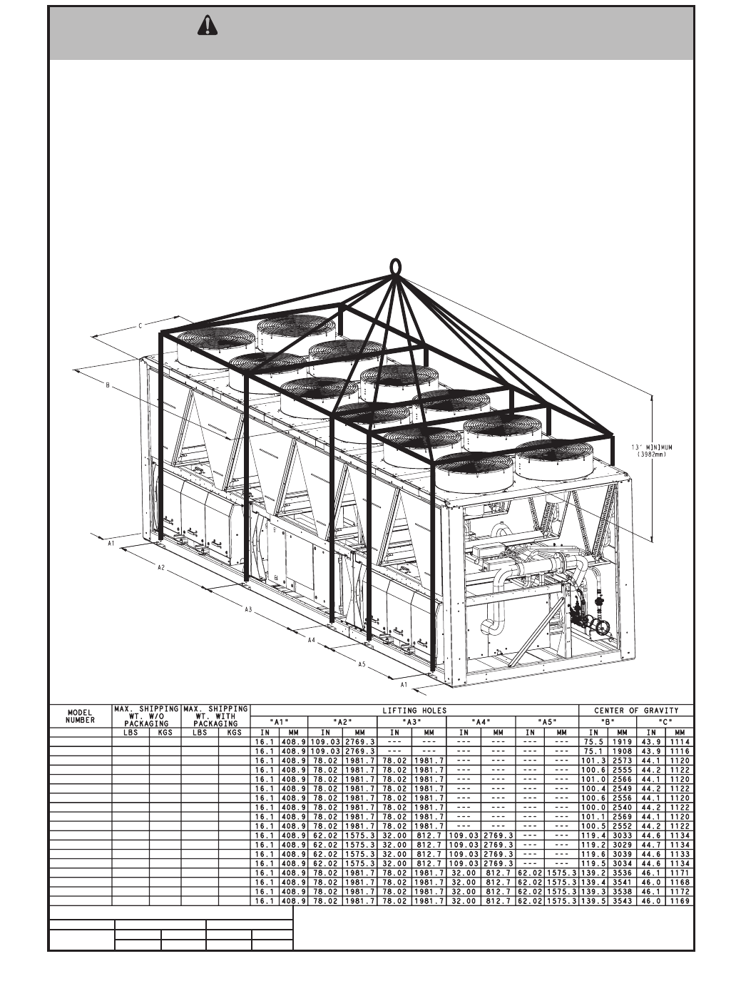
44
T
ALL PANELS MUST BE IN PLACE WHEN RIGGING. DO NOT ATTEMPT TO FORK THESE UNITS IF NO SKID IS SUPPLIED.
CAUTION - NOTICE TO RIGGERS:
NOTES:
1. 1.50 dia. (38.1mm) lifting holes provided for field supplied clevis.
2. Rig with a minimum of 25 ft (7620mm) length chains or cables.
3. If central lifting point is used, it must be a minimum of 13 ft. (3962mm) above the top of the unit.
4. Spreader bars made from steel or double nailed, and notched 2x6's approximately 8 ft. (2438mm) long, must
be placed just above the top of the unit (and stacks) to reduce the risk of damage to the top of the unit and
coils.
5. If overhead rigging is not available, the unit can be moved on rollers or dragged. When unit is moved on
rollers, the unit skid, if equipped, must be removed. To lift the unit, use jacks at the rigging points. Use a
minimum of one roller every 6 ft. (1829mm) to distribute the load. If the unit is to be dragged, lift the unit as
described above, and place unit on a pad. Apply moving force to the pad, not the unit. When in its final
location, raise the unit and remove the pad.
30XA080
30XA080-CU
30XA090
30XA090-CU
30XA100
30XA100-CU
30XA110
30XA110-CU
30XA120
30XA120-CU
30XA140
30XA140-CU
30XA160
30XA160-CU
30XA180
30XA180-CU
30XA200
30XA200-CU
8849
9573
9866
10831
10092
11057
10223
11188
10357
11322
12628
13834
12858
14065
14675
16122
14780
16227
4021
4350
4483
4922
4586
5024
4645
5084
4706
5145
5739
6287
5843
6392
6669
7327
6717
7375
9829
10553
10936
11901
11162
12127
11293
12258
11427
12392
13788
14994
14018
15225
15925
17372
16030
17477
4466
4795
4969
5408
5072
5511
5132
5570
5193
5631
6266
6814
6371
6919
7237
7895
7285
7943
LBSKGSLBSKGS
30XA090-160 958 435 1255 569
SUBSTRACT THESE VALUES FOR UNITS W/O PUMPS
SINGLE PUMP DUAL PUMP
Fig. 16 — Unit Rigging Label Detail 30XA080-200
a30-4427
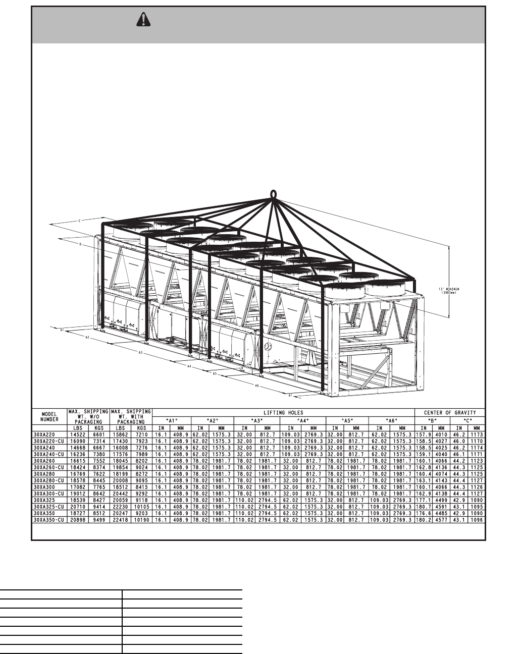
45
Table 2 — Number of Lifting Points for 30XA080-500
ALL PANELS MUST BE IN PLACE WHEN RIGGING. DO NOT ATTEMPT TO FORK THESE UNITS IF NO SKID IS SUPPLIED.
CAUTION - NOTICE TO RIGGERS:
NOTES:
1. 1.50 dia. (38.1mm) lifting holes provided for field supplied clevis.
2. Rig with a minimum of 25 ft (7620mm) length chains or cables.
3. If central lifting point is used, it must be a minimum of 13 ft. (3962mm) above the top of the unit.
4. Spreader bars made from steel or double nailed, and notched 2x6's approximately 8 ft. (2438mm) long, must
be placed just above the top of the unit (and stacks) to reduce the risk of damage to the top of the unit and
coils.
5. If overhead rigging is not available, the unit can be moved on rollers or dragged. When unit is moved on
rollers, the unit skid, if equipped, must be removed. To lift the unit, use jacks at the rigging points. Use a
minimum of one roller every 6 ft. (1829mm) to distribute the load. If the unit is to be dragged, lift the unit as
described above, and place unit on a pad. Apply moving force to the pad, not the unit. When in its final
location, raise the unit and remove the pad.
6. Check bill of lading for shipping weight of unit.
Fig. 17 — Unit Rigging Label Detail 30XA220-350
a30-4428
30XA UNIT SIZE NUMBER OF LIFTING POINTS
080 4
090-120 6
140, 160 8
180, 200 10
220-400 12
450, 500 14
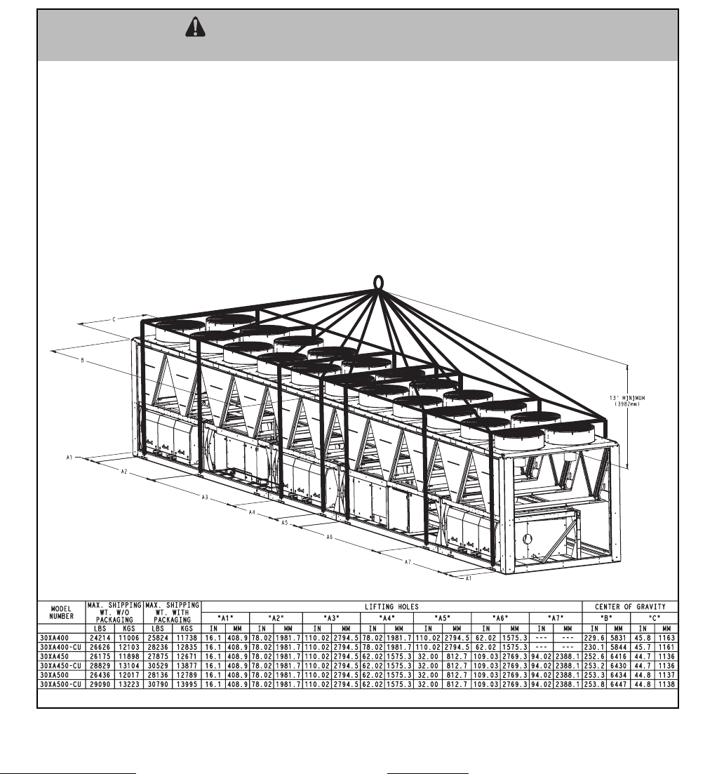
46
Minimum Loop Volume — The preferred minimum loop vol-
ume is dependent on the type of application. In order to obtain
leaving water temperature stability for comfort cooling appli-
cations, a minimum of 3 gallons per ton (3.25 liters per kW) is
required on all unit sizes. For process cooling applications, ap-
plications where high stability is critical, or operation at
ambient temperatures below 32 F (0° C) is expected, the loop
volume should be increased to 6 to 10 gallons per ton (6.46 to
10.76 liters per kW) of cooling. In order to achieve this
volume, it may be necessary to add a water storage tank to the
water loop. If a storage tank is added to the system, it should be
properly vented so that the tank can be completely filled and all
air eliminated. Failure to do so could cause lack of pump stabil-
ity and poor system operation. Any storage tank that is placed
in the water loop should have internal baffles to allow thorough
mixing of the fluid. See Fig. 24.
System Piping — Proper system design and installation proce-
dures should be followed closely. The system must be
constructed with pressure tight components and thoroughly
tested for installation leaks. Factory-supplied hydronic systems
are available with single or dual (for back-up) pumps. The
factory-installed system includes all of the components above
the line in Fig. 25 and 26.
Installation of water systems should follow sound engineer-
ing practice as well as applicable local and industry standards.
Improperly designed or installed systems may cause unsatis-
factory operation and/or system failure. Consult a water
treatment specialist or appropriate literature for information
regarding filtration, water treatment, and control devices. Fig-
ures 25 and 26 show a typical installation with components that
might be installed with the hydronic package of the 30XA unit.
ALL PANELS MUST BE IN PLACE WHEN RIGGING. DO NOT ATTEMPT TO FORK THESE UNITS IF NO SKID IS SUPPLIED.
CAUTION - NOTICE TO RIGGERS:
NOTES:
1. 1.50 dia. (38.1mm) lifting holes provided for field supplied clevis.
2. Rig with a minimum of 25 ft (7620mm) length chains or cables.
3. If central lifting point is used, it must be a minimum of 13 ft. (3962mm) above the top of the unit.
4. Spreader bars made from steel or double nailed, and notched 2x6's approximately 8 ft. (2438mm) long, must
be placed just above the top of the unit (and stacks) to reduce the risk of damage to the top of the unit and
coils.
5. If overhead rigging is not available, the unit can be moved on rollers or dragged. When unit is moved on
rollers, the unit skid, if equipped, must be removed. To lift the unit, use jacks at the rigging points. Use a
minimum of one roller every 6 ft. (1829mm) to distribute the load. If the unit is to be dragged, lift the unit as
described above, and place unit on a pad. Apply moving force to the pad, not the unit. When in its final
location, raise the unit and remove the pad.
6. Check bill of lading for shipping weight of unit.
Fig. 18 — Unit Rigging Label Detail 30XA400-500
a30-4428
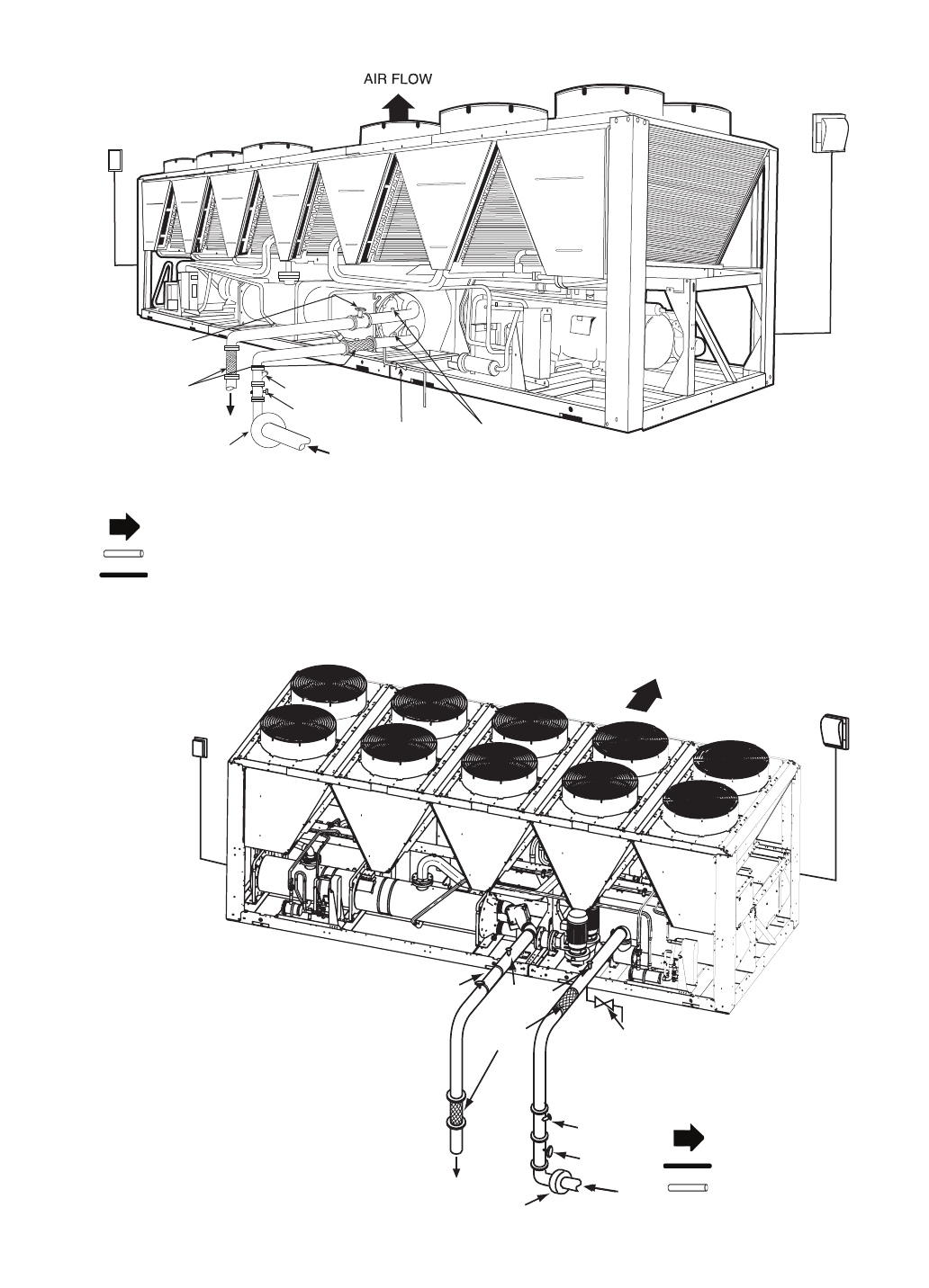
47
GATE VALVE*
STRAINER*
VIBRATION
ELIMINATORS*
BALANCING VALVE/
SHUT OFF*
POWER
FD
FD
CONTROL
PRESSURE/
TEMPERATURE TAPS*
PUMP
DRAIN
SHUTOFF
VALV E
NOTES:
1. Chiller must be installed level to maintain proper compressor oil return.
2. Piping shown are general points-of-connection guides only and are not
intended for a specific installation. Wiring and piping shown are for a quick
overview of system and are not in accordance with recognized standards.
3. All wiring must comply with applicable local and national codes.
4. All piping must follow standard piping techniques. Refer to Carrier System
Design Manual or appropriate ASHRAE (American Society of Heating,
Refrigeration, and Air Conditioning Engineers) handbook for details.
5. A 20 mesh strainer is required withinh 10 ft (3 m) of the cooler.
LEGEND
*Field-installed.
FD — Fused Disconnect
Airflow Through Condenser
Chilled Water Piping
Power Wiring
Fig. 19A — 30XA Typical Piping and Wiring (Units without Hydronic Package)
a30-4114
Fig. 19B — 30XA Typical Piping and Wiring (Units with Hydronic Package)
FIELD-SUPPLIED
FUSED DISCONNECT
CONTROL POWER
FIELD-SUPPLIED
FUSED DISCONNECT
UNIT POWER
AIRFLOW
DRAIN SHUTOFF VALVE
STRAINER*
GATE VALVE*
PUMP
PRESSURE/
TEMPERATURE
TAPS*
VIBRATION
ELIMINATORS*
BALANCING VALVE/
SHUTOFF*
NOTES:
1. Chiller must be installed level to maintain proper
compressor oil return and hydraulics.
2. Wiring and piping shown are general points-of-
connection guides only and are not intended for a
specific installation. Wiring and piping shown are
for a quick overview of system and are not in
accordance with recognized standards.
3. All wiring must comply with applicable local and
national codes.
4. All piping must follow standard piping techniques.
Refer to Carrier System Design Manual or appro-
priate ASHRAE (American Society of Heating,
Refrigeration, and Air Conditioning Engineers)
handbook for details.
5. Air separator required as close to chiller as possi-
ble (except primary/secondary systems).
6. 20 mesh strainer required for open loop systems.
LEGEND
*Field-installed.
Airflow Through Condenser
Power Wiring
Chilled Water Piping
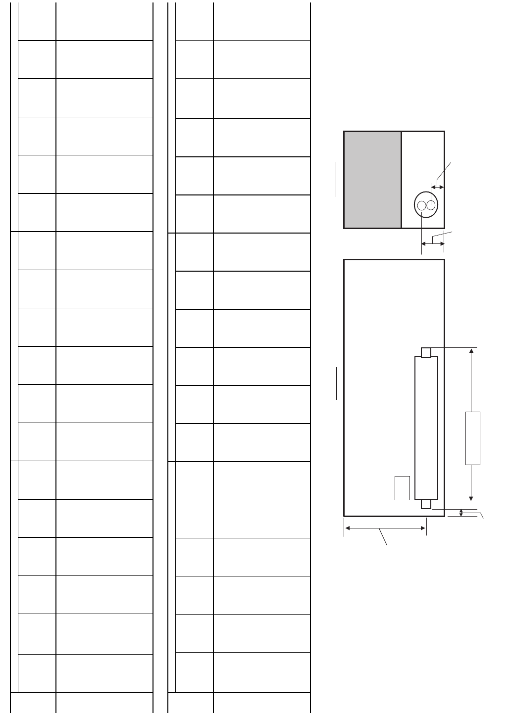
48
l
i
oC
r
e
loo
C
we
i
VediS
Distance to Entering
Water Connection
g
niv
ae
L
re
t
aW
Top View
Height Leaving
Water Connection
Height Entering
Water Connection
Distance to Leaving
Water Connection
Distance to
Leaving/Entering
Water Connection
ENGLISH
SI
*30XA400-500 units are equipped with standard coolers only. Refer to unit dimensional drawings for cooler dimensions.
NOTE: Refer to dimensional drawings for all other unit dimensions.
30XA
UNIT
SIZE*
STANDARD COOLER PLUS ONE PASS COOLER MINUS ONE PASS COOLER
Distance to
Leaving
Water
Connection
(in.)
Height
Leaving
Water
Connection
(in.)
Distance to
Leaving/
Entering
Water
Connection
(in.)
Distance to
Entering
Water
Connection
(in.)
Height
Entering
Water
Connection
(in.)
Victaulic
Connection
Size
(in.)
Distance to
Leaving
Water
Connection
(in.)
Height
Leaving
Water
Connection
(in.)
Distance to
Leaving/
Entering
Water
Connection
(in.)
Distance
to
Entering
Water
Connection
(in.)
Height
Entering
Water
Connection
(in.)
Victaulic
Connection
Size
(in.)
Distance to
Leaving
Water
Connection
(in.)
Height
Leaving
Water
Connection
(in.)
Distance to
Leaving/
Entering
Water
Connection
(in.)
Distance to
Entering
Water
Connection
(in.)
Height
Entering
Water
Connection
(in.)
Victaulic
Connection
Size
(in.)
080 121.2 19.1 68.1 121.2 10.85.0 1.5 19.6 68.1 121.2 10.3 4.0 –2.2 14.9 68.1 124.814.9 5.0
090 120.9 19.1 68.1 120.9 10.85.0 1.2 19.6 68.1 120.9 10.3 4.0 –2.5 14.9 68.1 124.5 14.9 5.0
100 120.9 19.1 68.1 120.9 10.85.0 1.2 19.6 68.1 120.9 10.3 4.0 –2.5 14.9 68.1 124.5 14.9 5.0
110 120.9 19.1 68.1 120.9 10.85.0 1.2 19.6 68.1 120.9 10.3 4.0 –2.5 14.9 68.1 124.5 14.9 5.0
120 120.9 19.1 68.1 120.9 10.85.0 1.2 19.6 68.1 120.9 10.3 4.0 –2.5 14.9 68.1 124.5 14.9 5.0
140 121.5 21.3 69.1 121.5 10.6 5.0 1.2 21.3 69.1 121.5 10.6 5.0 –2.2 15.9 69.1 124.815.9 6.0
160 121.5 21.3 69.1 121.5 10.6 5.0 1.2 21.3 69.1 121.5 10.6 5.0 –2.2 15.9 69.1 124.815.9 6.0
180 177.7 22.5 70.2 177.7 11.3 6.0 53.6 22.4 70.2 180.6 11.4 6.0 53.6 13.2 70.2 180.6 13.2 8.0
200 177.3 22.5 70.2 177.3 11.3 6.0 53.2 22.4 70.2 180.2 11.4 6.0 53.2 13.2 70.2 180.2 13.2 8.0
220 224.7 22.5 70.2 224.7 11.3 6.0 100.6 22.4 70.2 227.6 11.4 6.0 100.6 13.2 70.2 227.6 13.2 8.0
240 224.7 22.5 70.2 224.7 11.3 6.0 100.6 22.4 70.2 227.6 11.4 6.0 100.6 13.2 70.2 227.6 13.2 8.0
260 304.7 23.6 71.1 304.7 12.2 8.0 180.3 23.4 71.1 310.3 12.5 8.0 180.3 16.3 71.1 310.3 16.3 8.0
280 304.7 23.6 71.1 304.7 12.2 8.0 180.3 23.4 71.1 310.3 12.5 8.0 180.3 16.3 71.1 310.3 16.3 8.0
300 304.7 23.6 71.1 304.7 12.2 8.0 180.3 23.4 71.1 310.3 12.5 8.0 180.3 16.3 71.1 310.3 16.3 8.0
325 349.0 23.6 71.1 349.0 12.2 8.0 224.7 23.4 71.1 354.7 12.5 8.0 224.7 16.3 71.1 354.7 16.3 8.0
350 349.0 23.6 71.1 349.0 12.2 8.0 224.7 23.4 71.1 354.7 12.5 8.0 224.7 16.3 71.1 354.7 16.3 8.0
30XA
UNIT
SIZE*
STANDARD COOLER PLUS ONE PASS COOLER MINUS ONE PASS COOLER
Distance to
Leaving
Water
Connection
(mm)
Height
Leaving
Water
Connection
(mm)
Distance to
Leaving/
Entering
Water
Connection
(mm)
Distance to
Entering
Water
Connection
(mm)
Height
Entering
Water
Connection
(mm)
Victaulic
Connection
Size
(mm)
Distance to
Leaving
Water
Connection
(mm)
Height
Leaving
Water
Connection
(mm)
Distance to
Leaving/
Entering
Water
Connection
(mm)
Distance to
Entering
Water
Connection
(mm)
Height
Entering
Water
Connection
(mm)
Victaulic
Connection
Size
(mm)
Distance to
Leaving
Water
Connection
(mm)
Height
Leaving
Water
Connection
(mm)
Distance to
Leaving/
Entering
Water
Connection
(mm)
Distance to
Entering
Water
Connection
(mm)
Height
Entering
Water
Connection
(mm)
Victaulic
Connection
Size
(mm)
080 3077.8484.0 1728.7 3077.8274.2 127.0 37.9 497.2 1728.7 3077.8261.0 101.6 –55.1 379.1 1728.7 3170.7 379.1 127.0
090 3069.6 484.0 1728.7 3069.6 274.2 127.0 29.7 497.2 1728.7 3069.6 261.0 101.6 –63.2 379.1 1728.7 3162.6 379.1 127.0
100 3069.6 484.0 1728.7 3069.6 274.2 127.0 29.7 497.2 1728.7 3069.6 261.0 101.6 –63.2 379.1 1728.7 3162.6 379.1 127.0
110 3069.6 484.0 1728.7 3069.6 274.2 127.0 29.7 497.2 1728.7 3069.6 261.0 101.6 –63.2 379.1 1728.7 3162.6 379.1 127.0
120 3069.6 484.0 1728.7 3069.6 274.2 127.0 29.7 497.2 1728.7 3069.6 261.0 101.6 –63.2 379.1 1728.7 3162.6 379.1 127.0
140 3085.8540.5 1756.2 3085.8268.7 127.0 30.1 540.5 1756.2 3085.8268.7 127.0 –55.0 404.6 1756.2 3170.8404.6 152.4
160 3085.8540.5 1756.2 3085.8268.7 127.0 30.1 540.5 1756.2 3085.8268.7 127.0 –55.0 404.6 1756.2 3170.8404.6 152.4
180 4512.3 571.0 1782.1 4512.3 287.0 152.4 1361.4 569.5 1782.1 4587.2 288.5 152.4 1361.4 336.0 1782.1 4587.2 336.0 203.2
200 4502.4 571.0 1782.1 4502.4 287.0 152.4 1351.6 569.5 1782.1 4577.4 288.5 152.4 1351.6 336.0 1782.1 4577.4 336.0 203.2
220 5706.2 571.0 1782.1 5706.2 287.0 152.4 2555.3 569.5 1782.1 5781.1 288.5 152.4 2555.3 336.0 1782.1 5781.1 336.0 203.2
240 5706.2 571.0 1782.1 5706.2 287.0 152.4 2555.3 569.5 1782.1 5781.1 288.5 152.4 2555.3 336.0 1782.1 5781.1 336.0 203.2
260 7739.6 600.2 1804.9 7739.6 310.1 203.2 4580.8593.9 1804.9 7882.8316.5 203.2 4580.8413.3 1804.9 7882.8413.3 203.2
280 7739.6 600.2 1804.9 7739.6 310.1 203.2 4580.8593.9 1804.9 7882.8316.5 203.2 4580.8413.3 1804.9 7882.8413.3 203.2
300 7739.6 600.2 1804.9 7739.6 310.1 203.2 4580.8593.9 1804.9 7882.8316.5 203.2 4580.8413.3 1804.9 7882.8413.3 203.2
325 8865.1 600.2 1804.9 8865.1 310.1 203.2 5706.4 593.9 1804.9 9008.4 316.5 203.2 5706.4 413.3 1804.9 9008.4 413.3 203.2
350 8865.1 600.2 1804.9 8865.1 310.1 203.2 5706.4 593.9 1804.9 9008.4 316.5 203.2 5706.4 413.3 1804.9 9008.4 413.3 203.2
Fig. 20 — Cooler Option Dimensions
a30-4413
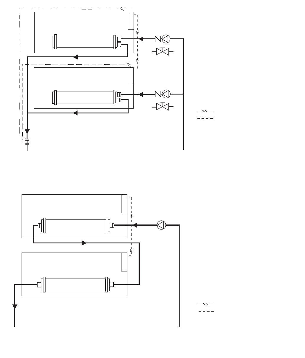
49
SLAVE CHILLER
CONTROL
BOX
PUMP
MASTER CHILLER
CONTROL
BOX
Fig. 22 — Series Dual Chiller Operation
LEGEND
LWT — Leaving Water Temperature
Field-Installed Communication Bus (slashes
indicate number of conductor wires)
Field-Installed Wiring
LEGEND
Field-Installed Communication Bus (slashes
indicate number of conductor wires)
Field-Installed Wiring
Fig. 21 — Parallel Dual Chiller Operation
a30-4417
a30-4418
SLAVE CHILLER
CONTROL
BOX
PUMP & CHECK VALVE
MASTER CHILLER
CONTROL
BOX
DUAL CHILLER
LWT SENSORS
& WELLS
OR ISOLATION VALVE
PUMP & CHECK VALVE
OR ISOLATION VALVE
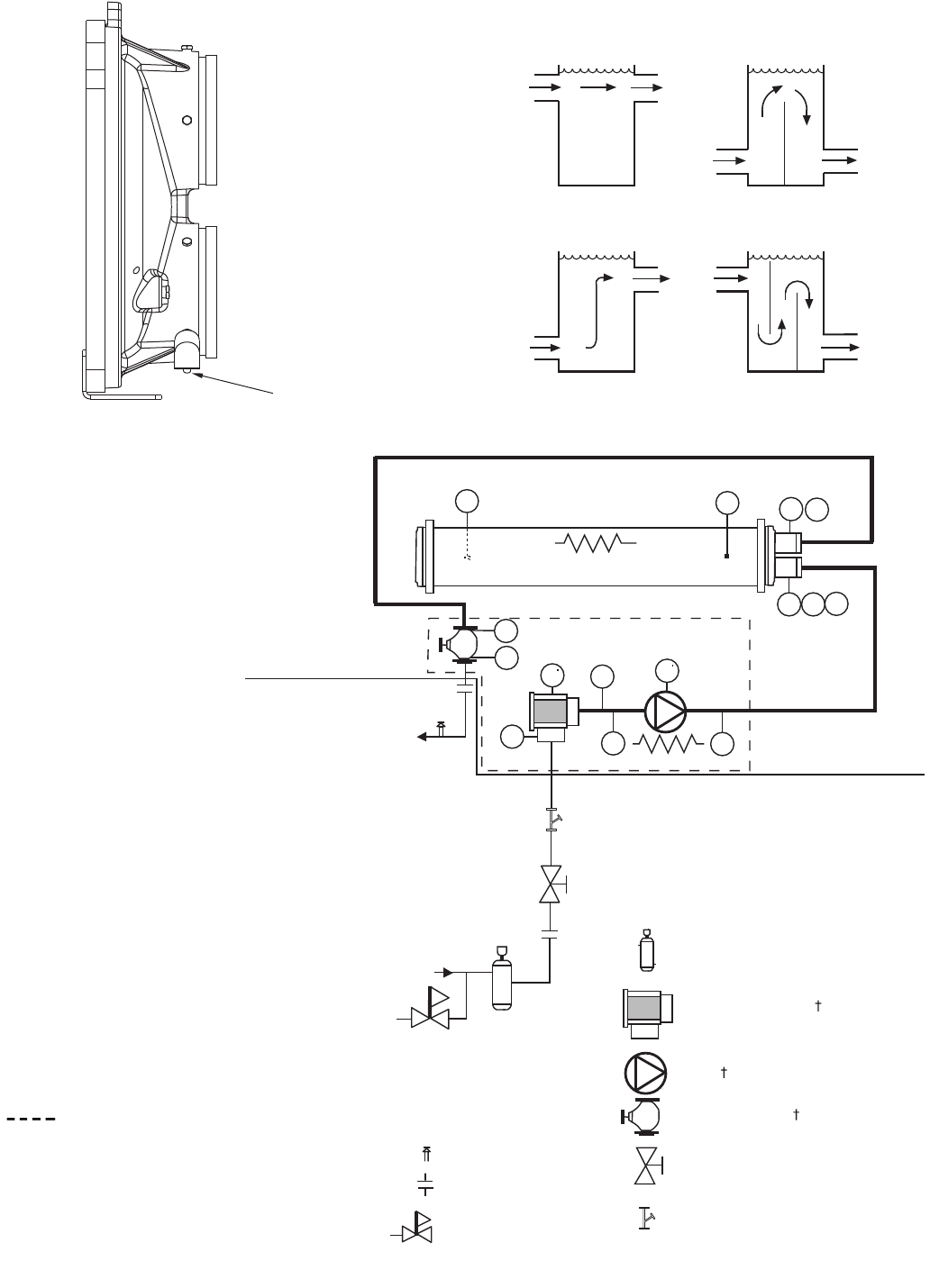
50
FLOW SWITCH
Fig. 23 — Flow Switch
a30-4138
BAD
BAD
GOOD
GOOD
Fig. 24 — Tank Baffling
a30-3185
PT
PT
T1
T2
FS
PP
PP
D
DV
D
PT
PT
Chilled
Water In
Chilled
Water Out
Heater
Heater
EPT
Air Separator with Vent*
Strainer/Suction Guide
Pump
Combination Valve
Isolation Valve*
Pressure Reducing
Fill Valve*
Flexible Connections*
Pressure Relief*
HYDRONIC PUMP PACKAGE
INSIDE
UNIT
OUTSIDE
UNIT
20 Mesh Stainer**
LEGEND
*Field-supplied and installed.
†Factory-installed option.
**Required for open loop systems.
D—Drain,3/4-in. NPT
D—Drain, 1/4-in. NPT
E—Expansion Tank Connection, 3/4-in. NPT
FS — Flow Switch
PP — Pipe Plug, 1/4-in. NPT
PT — Pressure/Temperature Tap
T1 — Leaving Water Thermistor
T2 — Entering Water Thermistor
V—Vent, 1/4-in. NPT
Indicates items provided with the
optional hydronic pump package.
Fig. 25 — Typical Piping Diagram on 30XA Units with Hydronic Package — Single Pump
a30-4414
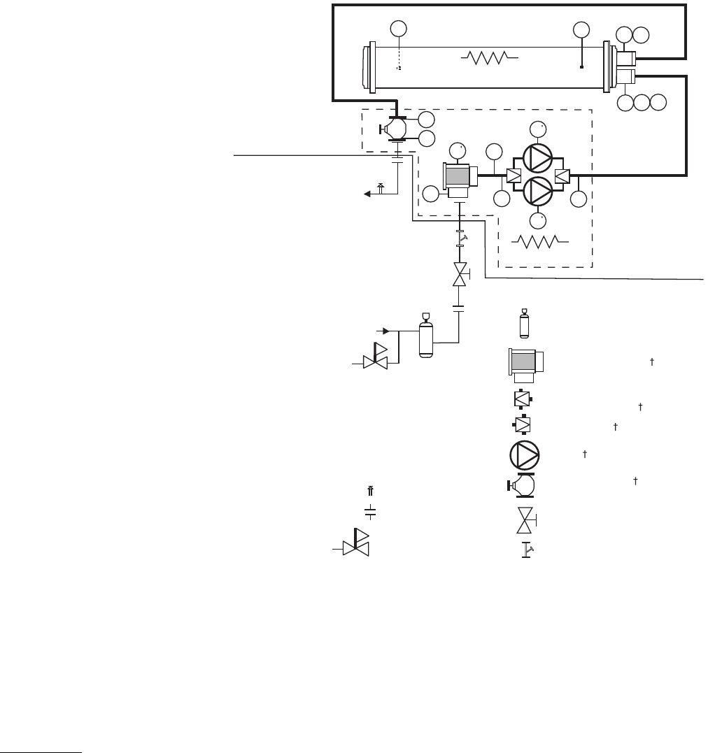
51
NOTE: It is recommended for units with the hydronic package
that an inlet isolation (shut-off) valve be placed exterior to the
unit to allow removal and service of the entire pump assembly,
if necessary. The hydronic package is supplied from the factory
with a combination valve for isolation of leaving water. Also,
if the unit is isolated with valves, a properly sized pressure
relief valve is recommended and should be installed in the pip-
ing between the unit and the valves, following all applicable
local codes.
Air Separation — For proper system operation, it is essential
that water loops be installed with proper means to manage air
in the system. Free air in the system can cause noise, reduce
terminal output, stop flow, or even cause pump failure due to
pump cavitation. For closed systems, equipment should be
provided to eliminate all air from the system.
The amount of air that water can hold in solution depends
on the pressure and temperature of the water/air mixture. Air is
less soluble at higher temperatures and at lower pressures.
Therefore, separation can best be done at the point of highest
water temperature and lowest pressure. Typically, this point
would be on the suction side of the pump as the water is return-
ing from the system or terminals. This is generally the optimal
place to install an air separator, if possible.
1. Install automatic air vents at all high points in the system.
(If the 30XA unit is located at the high point of the sys-
tem, a vent can be installed on the piping leaving the heat
exchanger on the 1/4 in. NPT female port.)
2. Install an air separator in the water loop, at the place
where the water is at higher temperatures and lower pres-
sures — usually in the chilled water return piping. On a
primary-secondary system, the highest temperature water
is normally in the secondary loop, close to the decoupler.
Preference should be given to that point on the system
(see Fig. 27). In-line or centrifugal air separators are read-
ily available in the field.
It may not be possible to install air separators at the place of
the highest temperature and lowest pressure. In such cases,
preference should be given to the points of highest temperature.
It is important that the pipe be sized correctly so that free air
can be moved to the point of separation. Generally, a water
velocity of at least 2 feet per second (0.6 m per second) will
keep free air entrained and prevent it from forming air pockets.
Automatic vents should be installed at all physically elevated
points in the system so that air can be eliminated during system
operation. Provisions should also be made for manual venting
during the water loop fill.
UNITS WITH HYDRONIC PUMP PACKAGE — The
30XA090-160 units can be equipped with a factory-installed
hydronic pump package consisting of a suction guide/strainer,
pump, combination valve, internal piping and wiring con-
nected at the factory.
PT
PT
T1 PP
PP
D
DV
D
PT
PT
Chilled
Water Out
Heater
Heater
E
D
PT
Air Separator with Vent*
Strainer/Suction Guide
Reverse Flow Check
Valve/Service Valve
Pump
Service Valve
Combination Valve
Isolation Valve*
Pressure Reducing
Fill Valve*
Flexible Connections*
Pressure Relief*
Chilled
Water In
HYDRONIC PUMP PACKAGE
INSIDE
UNIT
OUTSIDE
UNIT
20 Mesh Stainer**
T2
FS
LEGEND
*Field-supplied and installed.
†Factory-installed option.
**Required for open loop systems.
D—Drain,3/4-in. NPT
D—Drain, 1/4-in. NPT
E—Expansion Tank Connection, 3/4-in. NPT
FS — Flow Switch
PP — Pipe Plug, 1/4-in. NPT
PT — Pressure/Temperature Tap
T1 — Leaving Water Thermistor
T2 — Entering Water Thermistor
V—Vent, 1/4-in. NPT
Fig. 26 — Typical Piping Diagram on 30XA Units with Hydronic Package — Dual Pumps
a30-4415
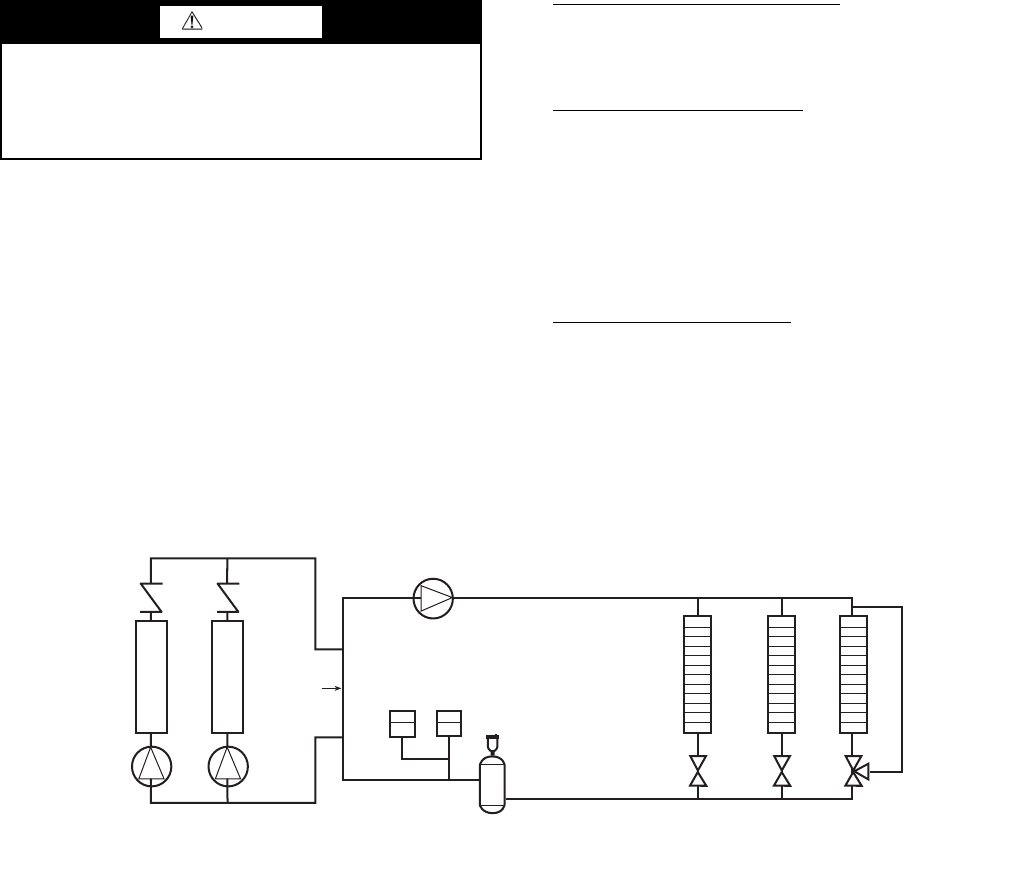
52
The combination valve performs the following functions:
• drip-tight shut-off valve
• spring closure design with a non-slam check valve
• flow-throttling valve
When facing the cooler side of unit, the inlet (return) water
connection is on the bottom. The outlet (supply) water connec-
tion is on the top. The inlet is connected to the suction guide/
strainer of the pump via a Victaulic-type connection. The cool-
er supply has water-side Victaulic-type connections (follow
connection directions as provided by the coupling manufactur-
er). Provide proper support for the piping. If accessory security
grilles have been added, holes must be cut in the grilles for
field piping and insulation.
There is a factory supplied, insulated 45-degree elbow pipe
and a victaulic coupling shipped with units ordered with a
hydronic pump package. Before starting field piping, use the
victaulic coupling to connect this elbow pipe to the outlet of the
combination valve.
The suction guide/strainer is shipped from the factory with a
run-in screen. This screen is a temporary device used during
the start-up/clean-up process of the chilled water circuit to
prevent construction debris from damaging the pump or
internal tubes of the cooler. After all debris has been removed
or a maximum of 24 running hours the temporary screen must
be removed. See the Start-Up, Controls, Operation and
Troubleshooting guide for further information.
NOTE: It is required that a 20 mesh field-supplied strainer be
installed in the inlet piping to the cooler on open loop systems.
A 3/4 in. NPT fitting is installed in the inlet piping of the
pump for connection to an expansion tank. Install the tank in
accordance with the manufacturer's instructions.
Figures 25 and 26 illustrate typical single and dual pump
packages.
Three drain connections are provided and are located at
leaving water (supply) end of cooler, pump volute, and the
suction guide. See Fig. 2-14 for connection location. Insulate
the drain piping (in the same manner as the chilled water pip-
ing) for at least 12 in. (305 mm) from the cooler.
UNITS WITHOUT HYDRONIC PUMP PACKAGE — When
facing the cooler side of the unit, the inlet (return) water connec-
tion is on the bottom. It is required that a field-supplied strainer
with a minimum size of 20 mesh be installed within 10 ft
(3.05 m) of the cooler inlet to prevent debris from damaging
internal tubes of the cooler. The outlet (supply) water connection
is on the top. The cooler has water-side victaulic-type connec-
tions (follow connection directions as provided by the coupling
manufacturer). Provide proper support for the piping. If accesso-
ry security grilles have been added, holes must be cut in the
grilles for field piping and insulation. See Fig. 28 for a typical
piping diagram of a 30XA unit without a hydronic pump pack-
age.
A drain connection is located at the leaving water (supply)
end of cooler. See Fig. 2-14 for connection location. Insulate
the drain piping (in the same manner as the chilled water
piping) for at least 12 in. (305 mm) from the unit.
DUAL CHILLER CONTROL — the ComfortLink™ con-
troller allows 2 chillers (piped in parallel or series) to operate as a
single chilled water plant with standard control functions
coordinated through the master chiller controller. This standard
ComfortLink feature requires a communication link between the
2 chillers.
There are several advantages to this type of control:
• redundancy (multiple circuits)
• better low load control, (lower tonnage capability)
• lower rigging lift weights (2 machines rather than 1 large
machine)
• chiller lead-lag operation (evens the wear between the
two machines)
Dual Chiller Leaving Water Sensor —If the dual chiller algo-
rithm is used, and the machines are installed in parallel, a dual
chilled water sensor must be installed for each module. Install
the well in the common leaving water header. See Fig. 21. The
series dual chiller application is shown in Fig. 22.
Parallel Dual Chiller Operation — Parallel chiller operation
is the recommended option for dual chiller control. In this case,
each chiller must control its own dedicated pump or isolation
valve. Balancing valves are recommended to insure proper
flow in each chiller. Two field-supplied and installed dual chill-
er leaving water temperature sensors are required, one for each
module for this function to operate properly.
Consider adding additional isolation valves to isolate each
chiller to allow for service on a machine, and still allow for par-
tial capacity from the other chiller. See Fig 21.
Series Dual Chiller Operation — Series chiller operation is an
alternate control method supported by the ComfortLink™
control system. Certain applications might require that the two
chillers be connected in series. For nominal 10º F (5.6º C) cool-
er ranges, use the minus 1 pass cooler arrangements to reduce
the fluid-side pressure drop. Use the standard cooler pass
arrangement for low flow, high cooler temperature rise
applications.
Consider adding additional piping and isolation valves to
isolate each chiller to allow for service on a machine, and still
allow for partial capacity from the other chiller. See Fig. 22.
CAUTION
The suction guide/strainer is shipped from the factory with
a run-in screen. This temporary screen must be removed
after all debris has been removed or a maximum of 24 run-
ning hours. Failure to remove the temporary screen may
result in damage to the pump or cooler.
Distribution Pump
Expansion
Tank(s)
Air Separator
with Vent
Decoupler
Chiller 1
Chiller 2
Zone 1
Zone 2
Zone 3
NOTE: Expansion tanks for 30XA hydronic kits must be installed for chillers piped in parallel in the primary water loop.
Fig. 27 — Typical Air Separator and Expansion Tank Location on Primary-Secondary Systems
a30-4002
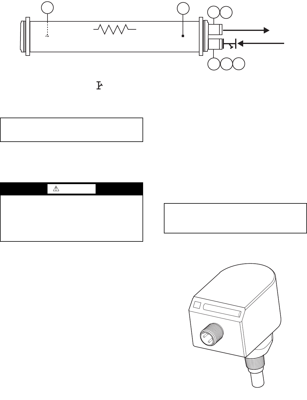
53
COOLER PUMP CONTROL — It is required that cooler
pump control be utilized on all chillers unless the chilled water
pump runs continuously or the chilled water system contains a
suitable antifreeze solution. Control of dual external pumps re-
quires installation of the external pump control accessory pack-
age (Part No. 00EFN900003200A).
If cooler pump control is not utilized, it is required that the
chiller be electrically interlocked with the chilled water pump
starter. The interlock should be wired to terminals TB5-1 and
TB5-2. It is also required that the cooler pump output be used
as an override to the chilled water pump control circuit to pro-
vide additional freeze protection.
Refer the control and power wiring schematic on page 63
for proper connection of the cooler pump output. The cooler
pump output will remain energized for 30 seconds after all
compressors stop due to an OFF command. In the event a
freeze protection alarm is generated, the cooler pump output
will be energized regardless of the cooler pump control soft-
ware configuration. The cooler pump output is also energized
anytime a compressor is started and when certain alarms are
generated. A thermal flow sensor is factory installed in the en-
tering fluid nozzle to prevent operation without flow through
the cooler. See Fig. 29. The flow sensor is factory wired.
Proper software configuration of the cooler pump control
parameters is required to prevent possible cooler freeze-up.
Refer to the Controls, Start-Up, Operation, Service and
Troubleshooting guide for more information.
BRINE UNITS — Special factory modifications to the units
are required to allow them to operate at fluid temperatures
less than 40 F (4.4 C). Be sure that the fluid has sufficient
inhibited glycol or other suitable corrosion-resistant anti-
freeze solution to prevent cooler freeze-up.
PREPARATION FOR YEAR-ROUND OPERATION — In
areas where the piping or unit is exposed to 32 F (0 C) or
lower ambient temperatures, freeze-up protection is required
using inhibited glycol or other suitable corrosion-resistant anti-
freeze solution and electric heater tapes. Heater tapes on piping
should have a rating for area ambient temperatures and be cov-
ered with a suitable thickness of closed-cell insulation. Route
power for the heater tapes from a separately fused disconnect.
Mount the disconnect within sight from the unit per local or
NEC (National Electric Code) codes. Identify disconnect at
heater tape power source with a warning that power must not
be turned off except when servicing unit.
A drain connection is located at the bottom of the cooler
head. See Fig. 2-14 for connection location. Install shut-off
valves to the drain line before filling the system with fluid.
T1
T2
PP
PP
DV
Heater (Optional)
Chilled Water Out
Chilled Water In
FS
LEGEND
D—Drain, 3/4-in. NPT
FS — Flow Switch
PP — Pipe Plug, 1/4-in. NPT
T1 — Leaving Water Thermistor
T2 — Entering Water Thermistor
V—Vent, 1/4-in. NPT
Fig. 28 — Typical Piping Diagram on 30XA Units without Hydronic Package
a30-4416
20 Mesh Stainer
20 Mesh Strainer
IMPORTANT: Automatic vents should be located in
accessible locations for maintenance purposes and
protected from freezing.
WARNING
Applications that utilize fresh water as the circulated fluid
require that the circulating pump be controlled directly by
the chiller. Operation with fresh water is not fail-safe
should there be a loss of power to the chiller or to the circu-
lating pump. Freeze damage due to power loss or disabling
chiller pump control in fresh water systems will impair or
otherwise negatively affect the warranty.
IMPORTANT: Adding antifreeze solution is the only
certain means of protecting the unit from freeze-up if
heater fails or electrical power is interrupted or lost
while temperatures are below 32 F (0 C).
Fig. 29 — Thermal Flow Sensor
a30-3432

54
Table 3 — 30XA Minimum and Maximum Cooler Flow Rates
* For applications requiring cooler leaving water temperature operation at less than
40 F (4.4 C), the units require the use of antifreeze and application may require
one of the special order brine option. Contact your local Carrier representative for
more information.
† For applications requiring cooler entering water temperature operation at less than
45 F (7.2 C), contact your local Carrier representative for unit selection using the
Carrier electronic catalog.
NOTE: Nominal flow rates required at ARI (Air Conditioning and Refrigeration
Institute) conditions 44 F (7 C) leaving fluid temperature, 54 F (12 C) entering
water temperature, 95 F (35 C) ambient. Fouling factor 0.00010 ft2-hr-F/Btu
(0.000018 m2-K/kW).
ITEM MINIMUM MAXIMUM NOMINAL
Cooler Leaving Water Temperature* 40 F (4.4 C) 60 F (15 C) —
Cooler Entering Water Temperature† 45 F (7.2 C) 70 F (21.1 C) —
30XA
UNIT SIZE Cooler Number of
Passes
Minimum Flow Rate Maximum Flow Rate Nominal Flow Rate
(gpm) (L/s) (gpm) (L/s) (gpm) (L/s)
080
Standard 2 95 6.0 379 23.9
180.4 11.4Plus one pass 3 43 2.7 192 12.1
Minus one pass 1 196 12.4 782 49.3
090
Standard 2 101 6.4 403 25.4
201.9 12.7Plus one pass 3 43 2.7 200 12.6
Minus one pass 1 229 14.4 917 57.9
100
Standard 2 101 6.4 403 25.4
225.5 14.2Plus one pass 3 43 2.7 200 12.6
Minus one pass 1 229 14.4 917 57.9
110
Standard 2 125 7.9 501 31.6
244.9 15.5Plus one pass 3 61 3.8244 15.4
Minus one pass 1 254 16.0 1014 64.0
120
Standard 2 125 7.9 501 31.6
264.816.7Plus one pass 3 73 4.6 293 18.5
Minus one pass 1 281 17.7 1124 70.9
140
Standard 2 134 8.5 53833.9
317.820.1Plus one pass 3 73 4.6 293 18.5
Minus one pass 1 324 20.4 1296 81.8
160
Standard 2 165 10.4 660 41.6
365.1 23.0Plus one pass 3 986.2 391 24.7
Minus one pass 1 354 22.3 141889.5
180
Standard 2 202 12.7 807 50.9
409.6 25.8Plus one pass 3 73 4.6 391 24.7
Minus one pass 1 416 26.2 1662 104.9
200
Standard 2 223 14.1 892 56.3
463.9 29.3Plus one pass 3 986.2 391 24.7
Minus one pass 1 45828.9 1833 115.6
220
Standard 2 235 14.8941 59.4
505.9 31.9
Plus one pass 3 122 7.7 489 30.9
Minus one pass 1 501 31.6 2004 126.4
240
Standard 2 266 16.81063 67.1
545.834.4Plus one pass 3 147 9.3 587 37.0
Minus one pass 1 53833.9 2151 135.7
260
Standard 2 257 16.2 1027 64.8
600.3 37.9Plus one pass 3 141 8.9 562 35.5
Minus one pass 1 584 36.82334 147.3
280
Standard 2 293 18.5 1173 74.0
642.2 40.5Plus one pass 3 141 8.9 562 35.5
Minus one pass 1 620 39.1 2481 156.5
300
Standard 2 327 20.6 130882.5
687.5 43.4Plus one pass 3 174 11.0 697 44.0
Minus one pass 1 687 43.3 2750 173.5
325
Standard 2 361 22.81442 91.0
733.4 46.3Plus one pass 3 211 13.3 843 53.2
Minus one pass 1 724 45.7 2897 182.8
350
Standard 2 379 23.9 1516 95.6
775.4 48.9Plus one pass 3 244 15.4 97861.7
Minus one pass 1 767 48.4 3068193.6
400
Standard 1 501 31.6 2004 126.4
917.6 57.9Plus one pass — — — — —
Minus one pass — — — — —
450
Standard 1 501 2004
1019.3 64.3Plus one pass — — — — —
Minus one pass — — — — —
500
Standard 1 501 2004
1092.868.9Plus one pass — — — — —
Minus one pass — — — — —
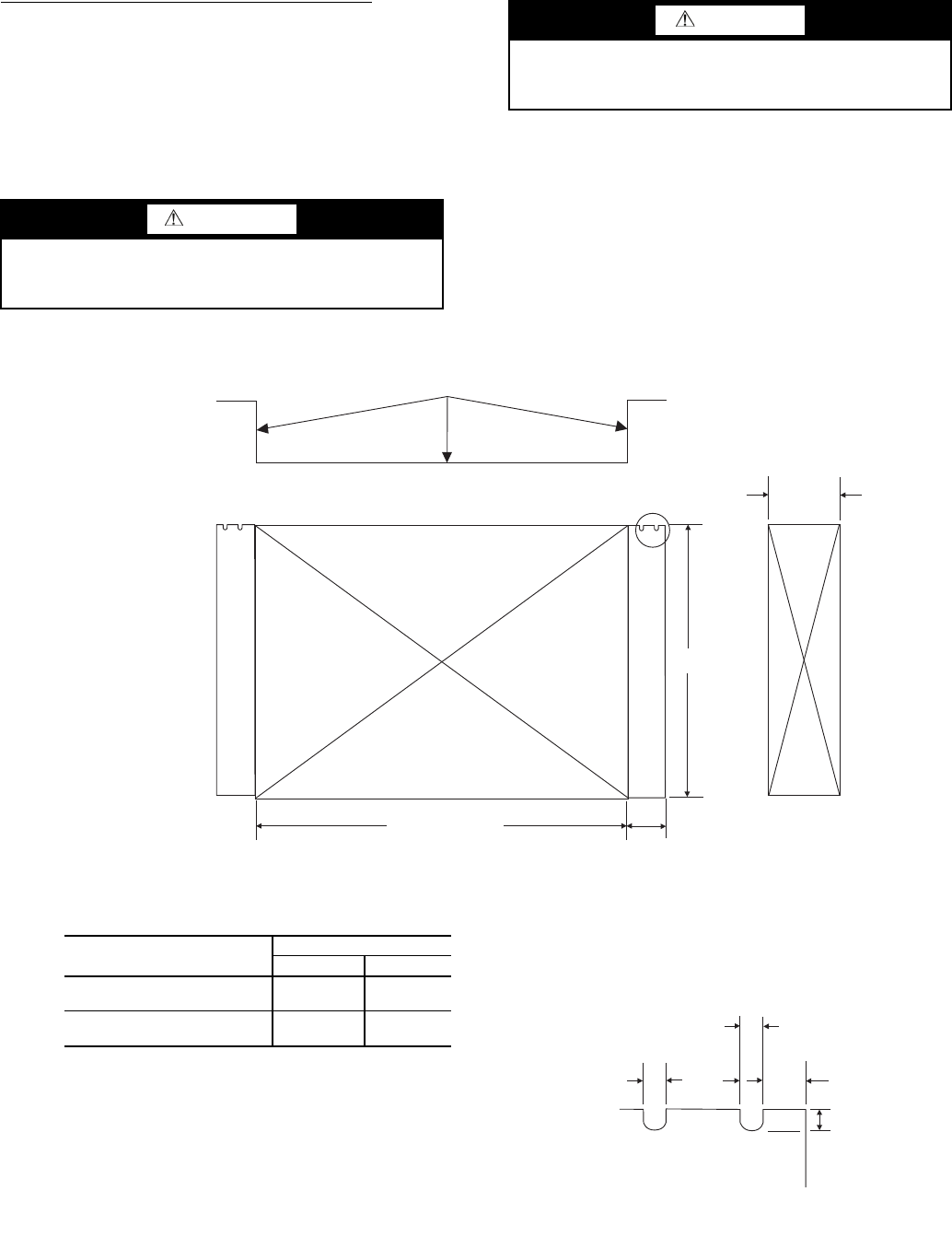
55
Low Ambient Temperature Head Pressure Control — If the
unit is equipped with the low ambient temperature head pres-
sure control option, field-fabricated and field-installed wind
baffles are required if the wind velocity is anticipated to be
greater than 5 mph (8 km/h). Two different baffles may be re-
quired, facing the control box. Wind baffles should be con-
structed with minimum 18-gage galvanized sheet metal or oth-
er suitable corrosion-resistance material with cross breaks for
strength. See Fig. 30. Use field-supplied screws to attach baf-
fles to the corner posts of the machine. Be sure to hem or turn a
flange on all edges to eliminate sharp edges on the baffles.
Mount the smaller height baffle on units with a control box
located on the end of the unit. It is recommended that the upper
notches be used for mounting the baffles. This reduces the risk
of damaging the coil while drilling a mounting hole. Loosen
the upper corner post bolts and slide the baffle under the bolt
and washer. Tighten the bolt. Drill holes in the bottom of the
flange of the baffle and mount with two screws to secure the
bottom of the baffle to the corner post. Repeat the process for
the opposite end. See Fig. 30.
WARNING
Disconnect all power to the unit before performing mainte-
nance or service. Electrical shock and personal injury could
result.
CAUTION
To avoid damage to the refrigerant coils and electrical com-
ponents, use extreme care when drilling screw holes and
screwing in fasteners.
Cross break these faces.
Hem these 3 edges both top
and bottom.
See Detail A
1880 [74.0]
Detail A
Typical Both Flanges
X
180 [7.0]
18 [0.75] 31 [1.25]
18 [0.75]
21 [0.88]
70 [2.75]
305 [12.0]
Fig. 30 — Field-Fabricated and Field-Installed Wind Baffles
NOTES:
1. Material: 18 ga. Corrosion Resistant Sheet Metal.
2. Dimensions are in mm [inches].
POSITION BAFFLE HEIGHT (X)
RIGHT END LEFT END
30XA080-120
(Facing the control box end) 1040 [41.0] 635 [25.0]
30XA140-500
(Facing the control box end) 1040 [41.0] 1040 [41.0]
a30-3997
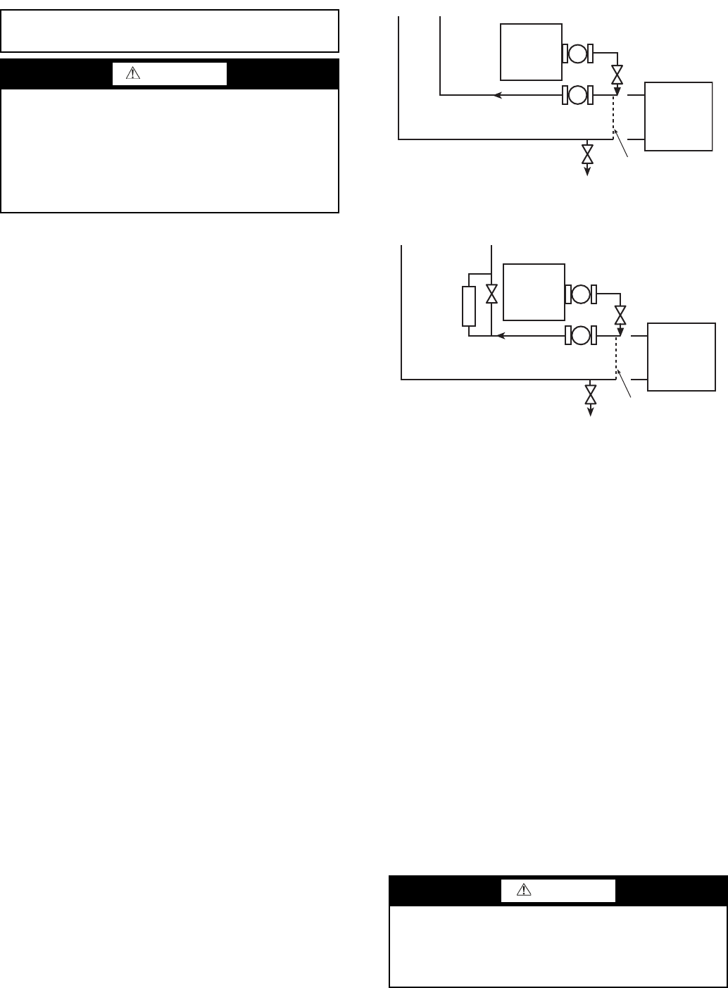
56
Step 4 — Fill the Chilled Water Loop.
The chilled water pump (if equipped) is rated for 150 psig
(1034 kPa) duty. The maximum cooler fluidside pressure is
300 psig (2068 kPa). Check the pressure rating for all of the
chilled water devices installed. Do not exceed the lowest pres-
sure rated device.
WATER SYSTEM CLEANING — Proper water system
cleaning is of vital importance. Excessive particulates in the
water system can cause excessive pump seal wear, reduce or
stop flow, and cause damage of other components.
1. Install a temporary bypass around the chiller to avoid
circulating dirty water and particulates into the pump
package and chiller during the flush. Use a temporary
circulating pump during the cleaning process. Also, be
sure that there is capability to fully drain the system after
cleaning. See Fig. 31.
2. Be sure to use a cleaning agent that is compatible with
all system materials. Be especially careful if the system
contains any galvanized or aluminum components. Both
detergent-dispersant and alkaline-dispersant cleaning
agents are available.
3. It is recommended to fill the system through a water me-
ter. This provides a reference point for the future for loop
volume readings, and it also establishes the correct quan-
tity of cleaner needed in order to reach the required
concentration.
4. Use a feeder/transfer pump to mix the solution and fill the
system. Circulate the cleaning system for the length of
time recommended by the cleaning agent manufacturer.
a. After cleaning, drain the cleaning fluid and flush the
system with fresh water.
b. A slight amount of cleaning residue in the system can
help keep the desired, slightly alkaline, water pH of 8
to 9. Avoid a pH greater than 10, since this will
adversely affect pump seal components.
c. A side stream filter is recommended (see Fig. 32 dur-
ing the cleaning process). Filter side flow rate should
be enough to filter the entire water volume every 3 to
4 hours. Change filters as often as necessary during
the cleaning process.
d. Remove temporary bypass when cleaning is complete.
A suction guide with an internal strainer is standard on all
30XA units with factory-installed hydronic packages. This
strainer allows removal of particulates from the chilled
water loop. Using the combination valve and the field-installed
isolation valve at the inlet, the strainer can be isolated from the
chilled water loop to be cleaned.
The Carrier ComfortLink™ controls provided have a built-
in feature to remind building owners or operators to clean the
strainer at a pre-set time interval. Properly installed, cleaned
and maintained systems will rarely need the strainer cleaned
after the initial fill. This time interval is user-configurable.
Ideally, the chilled water loop will be cleaned before the unit
is connected. If the run-in screen is left in the suction guide/
strainer, it is recommended that the Service Maintenance be set
to alert the operator within 24 hours of start-up to be sure that
the run-in screen in the suction guide/strainer is removed after
24 hours of operation.
NOTE: The suction guide/strainer must be removed after the
first 24 hours of operation.
To set the time for the parameter, go to Time
Clock
MCFG
W.FIL in the handheld Navigator™ display.
To set the time for the parameter with the Touch Pilot™ dis-
play, go to Main Menu
Service
MAINTCFG
wfilter_c.
Values for this item are input in days.
WATER TREATMENT — Fill the fluid loop with water (or
brine) and a corrosion-resistant inhibitor suitable for the water
of the area. Consult the local water treatment specialist for
characteristics of system water and a recommended inhibitor
for the cooler fluid loop.
Untreated or improperly treated water may result in corro-
sion, scaling, erosion, or algae. The services of a qualified wa-
ter treatment specialist should be obtained to develop and mon-
itor a treatment program.
IMPORTANT: Before starting unit, be sure all of the
air has been purged from the system.
WARNING
In low ambient (below 32 F [0° C]) and/or low leaving
fluid temperature applications (below 40 F [4.4° C]), a suit-
able antifreeze solution of the proper concentration for the
specific operating conditions must be used as the fluid cir-
culated through the cooler to prevent freezing and damage
to the system. Failure to operate the system with an anti-
freeze solution of the proper concentration will void the
warranty should damage result from freezing.
CAUTION
Water must be within design flow limits, clean, and treated
to ensure proper chiller performance and reduce the poten-
tial of tube damage due to corrosion, scaling, erosion, and
algae. Carrier assumes no responsibility for chiller damage
resulting from untreated or improperly treated water.
x
x
DILUTED
CLEANING
AGENT
SYSTEM
POT FEEDER AND
TRANSFER PUMP
30XA UNIT
TEMPORARY
BYPASS
TEMPORARY
PUMP
TO DRAIN
Fig. 31 — Typical Set Up for Cleaning Process
a30-4411
x
x
DILUTED
CLEANING
AGENT
SYSTEM
SIDE
STREAM
FILTER
POT FEEDER AND
TRANSFER PUMP
30XA UNIT
TEMPORARY
PUMP
TEMPORARY
BYPASS
TO DRAIN
Fig. 32 — Cleaning Using a Side Stream Filter
a30-4412
57
NOTE: Do not use automobile anti-freeze, or any other fluid
that is not approved for heat exchanger duty. Only use appro-
priately inhibited glycols, concentrated to provide adequate
protection for the temperature considered.
SYSTEM PRESSURIZATION — A proper initial cold fill
pressure must be established before filling of the unit. The
initial cold fill pressure is the pressure applied at the filling
point to fill a system to its highest point, plus a minimum
pressure at the top of the system (4 psig minimum [27.6 kPa])
to operate air vents and positively pressurize the system. The
expansion tank is very important to system pressurization. The
expansion tank serves several purposes:
1. Provide NPSHR (Net Positive Suction Head Required)
for the pump to operate satisfactorily.
2. Set system pressure.
3. Accommodate expansion/contraction of water due to
temperature changes.
4. Acts as a pressure reference for the pump.
The expansion tank pressure must be set BEFORE the
system is filled. Follow the manufacturer’s recommendation
for instructions on setting the pressure in the expansion tank.
NPSHR information is provided on the Pump Curves in
Fig. 33-36 for units with factory-installed hydronic kits. See
Table 4 for pump impeller sizes.
Once the system is pressurized, the pressure at the connec-
tion point of the expansion tank to water piping will not change
unless the water loop volume changes (either due to addition/
subtraction of water or temperature expansion/contraction).
The pressure at this point remains the same regardless of
whether or not the pump is running.
Since the expansion tank acts as a reference point for the
pump, there cannot be two reference points (two expansion
tanks) in a system, unless manifolded together. Where two or
more 30XA chillers with the hydronic option are installed in
parallel, there should not be more than one expansion tank in
the system, unless manifolded together as seen in Fig. 27. It is
permissible to install the expansion tank(s) in a portion of the
return water line that is common to all pumps, providing that
the tank is properly sized for combined system volume.
If the application involves two or more chillers in a primary
secondary system, a common place for mounting the expan-
sion tank is in the chilled water return line, just before the
decoupler. See Fig. 27 for placement of expansion tank in
primary-secondary systems.
If a diaphragm expansion tank is utilized (a flexible
diaphragm physically separates the water/air interface) it is not
recommended to have any air in the water loop. See the section
on air separation on page 51 for instructions on providing air
separation equipment.
FILLING THE SYSTEM — The initial fill of the chilled
water system must accomplish three goals:
1. The entire piping system must be filled with water.
2. The pressure at the top of the system must be high enough
to vent air from the system (usually 4 psig [27.6 kPa] is
adequate for most vents).
3. The pressure at all points in the system must be high
enough to prevent flashing in the piping or cavitation in
the pump.
The pressure created by an operating pump affects system
pressure at all points except one — the connection of the
expansion tank to the system. This is the only location in the
system where pump operation will not give erroneous pressure
indications during the fill. Therefore, the best location to install
the fill connection is close to the expansion tank. An air vent
should be installed close by to help eliminate air that enters
during the fill procedure.
When filling the system, ensure the following:
1. Remove temporary bypass piping and cleaning/flushing
equipment.
2. Check to make sure all drain plugs are installed.
Normally, a closed system needs to be filled only once. The
actual filling process is a fairly simple procedure. All air should
be purged or vented from the system. Thorough venting at high
points and circulation at room temperature for several hours is
highly recommended.
NOTE: Local codes concerning backflow devices and other
protection of the city water system should be consulted and
followed to prevent contamination of the public water supply.
This is critical when antifreeze is used in the system.
SET WATER FLOW RATE — Once the system is cleaned,
pressurized, and filled, the flow rate through the chiller needs
to be established. On units with the hydronic package, this can
be accomplished by using the balancing valve. Follow the
manufacturer’s recommendations for setting the balancing
valve. Local codes may prohibit restricting the amount of water
using the balancing valve for a given motor horsepower. In this
case, use the method listed in the Pump Modification/
Trimming section. See below for the type of combination valve
in 30XA units with the optional hydronic package.
NOTE: Carrier recommends a differential pressure gage when
measuring pressures across the pumps or balancing valves.
This provides for greater accuracy and reduces error build-up
that often occurs when subtracting pressures made by different
gages.
A rough estimate of water flow can also be obtained from
the pressure gages across the 30XA heat exchanger.
Figure 33 and 34 shows the relationship between gpm and
heat exchanger pressure drop. It should be noted that these
curves are for fresh water and “clean” heat exchangers; they do
not apply to heat exchangers with fouling. To read the chart,
subtract the readings of the two pressure gages on the hydronic
kit. This number is the pressure drop across the heat exchanger.
Adjust the factory-installed balancing valve or external balanc-
ing valve (in units without hydronic package) until the correct
pressure drop is obtained for the required flow.
Table 4 — Pump Impeller Sizes
*Option Code refers to the Hydronics Option (position 11) in the model number. See Fig. 1 for option identification.
30XA UNIT SIZE SINGLE/DUAL PUMP
090-160 FTV-5 in.
30XA
UNIT SIZE
PUMP
Hp
SINGLE PUMP DUAL PUMP
Option Code* Rpm Impeller Dia.
(in.) Pump Curve Option Code* Rpm Impeller Dia.
(in.) Pump Curve
090-160
5 1 3450 4.5 I 7 3450 4.5 II
7.5 2 3450 5 I 83450 5 II
10 3 3450 5.4 I B 3450 5.4 II
15 4 3450 6.1 I C 3450 6.1 II
58
0
20
40
60
80
100
120
140
160
0 100 200 300 400 500
GPM
Available Head (Feet)
1
2
3
4
0
20
40
60
80
100
120
140
160
0 100 200 300 400 500
GPM
Available Head (Feet)
1
2
4
3
0
20
40
60
80
100
120
140
160
0 100 200 300 400 500
GPM
Available Head (Feet)
1
2
3
4
0
20
40
60
80
100
120
140
160
0 100 200 300 400 500
GPM
Available Head (Feet)
1
2
3
4
0
20
40
60
80
100
120
140
160
0 100 200 300 400 500
GPM
Available Head (Feet)
1
3
4
2
Fig. 33 — 30XA090-160 Single Pump Envelope Curves
30XA090,100
30XA110
30XA120
30XA140
30XA160
Selection Pump
1 Single 5HP
2 Single 7.5HP
3 Single 10HP
4 Single 15HP
a30-4431
a30-4432
a30-4433
a30-4434
a30-4435
59
30XA090,100
30XA110
30XA120
30XA140
30XA160
Selection Pump
7 Dual 5HP
8Dual 7.5HP
B Dual 10HP
C Dual 15HP
Fig. 34 — 30XA090-160 Dual Pump Envelope Curves
a30-4436
a30-4437
a30-4438
a30-4439
a30-4440
0
20
40
60
80
100
120
140
160
0 100 200 300 400 500
GPM
Available Head (Feet )
7
8
B
C
0
20
40
60
80
100
120
140
160
0 100 200 300 400 500
GPM
Available Head (Feet )
7
8
B
C
0
20
40
60
80
100
120
140
160
0 100 200 300 400 500
GPM
Available Head (Feet )
7
8
B
C
0
20
40
60
80
100
120
140
160
0 100 200 300 400 500
GPM
Available Head (Feet )
7
8
B
C
0
20
40
60
80
100
120
140
160
0 100 200 300 400 500
GPM
Available Head (Feet )
7
8
B
C
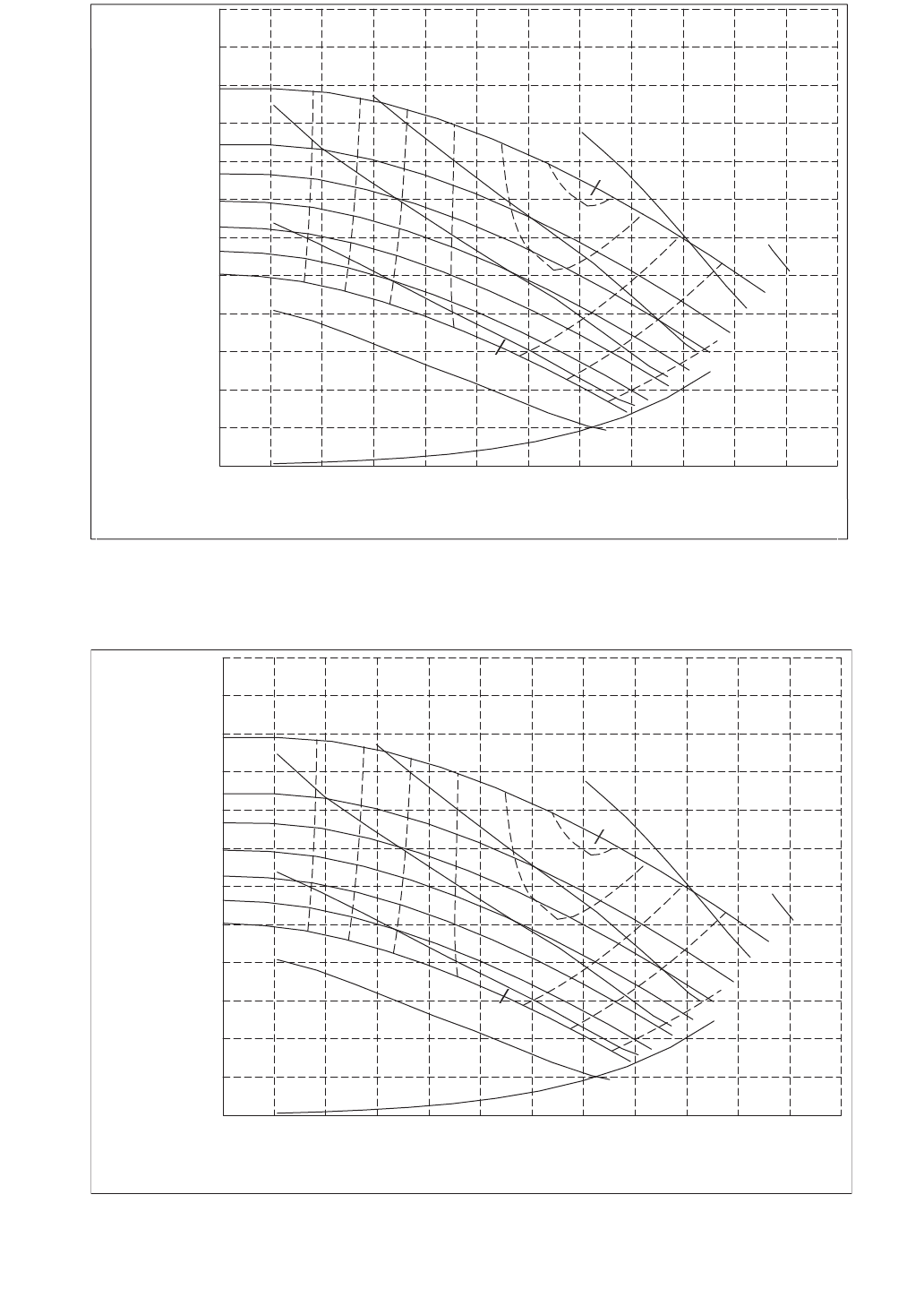
60
0
0.00
100
6.31
200
12.62
300
18.93
400
25.24
500
31.54
(gpm)
(l/s)
(0.0) 0
(9.1) 30
(18.3) 60
(27.4) 90
(36.6) 120
(45.7) 150
Head Pressure
(m) ft of Fluid
3450 RPM
N
P
S
H
r
4.75 in
5.00 in
5.25 in
5.50 in
5.75 in
77
77
74
74
70
70
62
62
52
52%
39
NPSHr
3 hp
5 hp
7.5 hp
10 hp
15 hp
20 hp
6.19 in
4.50 in
77
Flow Rate
0
0.00
100
6.31
200
12.62
300
18.93
400
25.24
500
31.54
(gpm)
(l/s)
(0.0) 0
(9.1) 30
(18.3) 60
(27.4) 90
(36.6) 120
(45.7) 150
Head Pressure
(m) ft of Fluid
Flow Rate
3450 RPM
N
P
S
H
r
4.75 in
5.00 in
5.25 in
5.50 in
5.75 in
77
77
74
74
70
70
62
62
52
52%
39
NPSHr
3 hp
5 hp
7.5 hp
10 hp
15 hp
20 hp
6.19 in
4.50 in
77
LEGEND
NPSHr — Net Positive Suction Head (Pressure) Required
NOTE: Refer to Fig. 1 for option identification. Refer to Table 4 for more information.
Fig. 35 — Pump Curve I for Hydronic Package Single Pump (Fresh Water)
LEGEND
NPSHr — Net Positive Suction Head (Pressure) Required
NOTE: Refer to Fig. 1 for option identification. Refer to Table 4 for more information.
Fig. 36 — Pump Curve II for Hydronic Package Dual Pump (Fresh Water)
a30-4441
a30-4442

61
PUMP MODIFICATION/TRIMMING — Since the pumps
are constant speed, the only way to obtain greater flow with a
given pump/impeller is to decrease system head. This will
allow the pump to “ride” its curve to the right, resulting in
increased flow. If greater flow is necessary, consider opening
the combination valve. Also, verify that the strainer is clean,
and that no unnecessary system resistance is present, such as
partially closed isolation valves.
Once the combination valve is set, note the stem position. If
later service work requires the valve to be closed, it will be easier
to re-balance the system, if the original balance point is known.
Increasing system resistance by closing the balancing valve
will force the pump to “ride” its curve to the left, resulting in
less flow. Although this does reduce power consumption
slightly, it may not be the desirable method of reducing the
flow, especially if a large reduction is needed.
The other method for reducing flow on a constant speed
pump is impeller trimming. The impellers in the pumps provid-
ed in the 30XA hydronic kit can be easily removed for this
purpose. Refer to the vendor literature packet supplied with the
hydronic package information on Seal Replacement in the
Service section, and follow instructions for impeller removal
and trimming. See Fig. 33 and 34 for pump envelope curve in-
formation. Trimming should only be done by a qualified ma-
chine shop that has experience in this operation. Contact your
local Carrier representative for a recommended machine shop.
Impeller trimming has the added benefit of maximum bhp
(brake horsepower) savings, which can recover the cost
incurred by performing the impeller trimming.
FREEZE PROTECTION — The 30XA units are provided
with a flow switch to protect against freezing situations that
occur from no water flow. While the flow switch is helpful in
preventing freezing during no-flow situations, it does not
protect the chiller in case of power failure during sub-freezing
ambient temperatures, or in other cases where water tempera-
ture falls below the freezing mark. Appropriate concentrations
of inhibited propylene or ethylene glycol or other suitable
inhibited antifreeze solution should be considered for chiller
protection where ambient temperatures are expected to fall
below 32 F (0° C). Consult local water treatment specialist on
characteristics of the system water and add a recommended
inhibitor to the chilled water. The Carrier warranty does not
cover damage due to freezing.
If the pump will be subjected to freezing temperatures, steps
must be taken to prevent freeze damage. If the pump will not
be used during this time, it is recommended to drain the pump
and hydronic package and these components are backflushed
with inhibited glycol. Otherwise, a glycol-water solution
should be considered as the heat transfer fluid. Drains are locat-
ed on the pump(s) and suction guide/strainer for units with hy-
dronic kits. Units without hydronic kits have a drain plug
mounted on the bottom of the cooler head at each end of the
cooler.
NOTE: Do not use automobile anti-freeze, or any other fluid
that is not approved for heat exchanger duty. Only use
appropriately inhibited glycols, concentrated to provide ade-
quate protection for the temperature considered.
Use an electric tape heater for the external piping, if unit
will be exposed to freezing temperatures.
Ensure that power is available to the chiller at all times,
even during the off-season, so that the pump and cooler heaters
have power. Also make sure that the piping tape heaters have
power.
On units with pump packages, a heater is supplied with the
hydronic package that will protect this section from freezing in
outdoor-air temperatures down to –20 F (–29 C), except in the
case of a power failure. The Carrier warranty does not cover
damage due to freezing.
All units are equipped with cooler heaters. Units are protect-
ed from freezing down to 0° F (–18 C) through the cooler heat-
ers and control algorithms. If the unit controls the chilled water
pump and valves, allowing flow through the cooler, the unit is
protected from freezing down to –20 F (–29 C). The Carrier
warranty does not cover damage due to freezing.
PREPARATION FOR WINTER SHUTDOWN — If the unit
is not operational during the winter months, at the end of cooling
season complete the following steps.
1. If the unit has optional heater tapes on the cooler and the
cooler will not be drained, do not shut off power discon-
nect during off-season shutdown. If the unit has optional
heater tapes on the cooler and the cooler is drained, open
the circuit breaker for the heater, CB-13 or shut off power
during off-season shutdown.
2. Draining the fluid from the system is highly recommend-
ed. If the unit is equipped with a hydronic package, there
are additional drains in the pump housing and strainer
that must be opened to allow for all for all of the water to
drain.
3. Isolate the cooler from the rest of the system with water
shutoff valves.
4. Replace the drain plug and completely fill the cooler with
a mixture of water and a suitable corrosion-inhibited anti-
freeze solution such as propylene glycol. The concentra-
tion should be adequate to provide freeze protection to
15° F (8.3° C) below the expected low ambient tempera-
ture conditions. Antifreeze can be added through the vent
on top of the cooler. If the unit has a hydronic pump pack-
age, the pump must be treated in the same manner.
5. Leave the cooler filled with the antifreeze solution for the
winter, or drain if desired. Be sure to deenergize heaters
(if installed) as explained in Step 1 to prevent damage.
Use an approved method of disposal when removing anti-
freeze solution.
At the beginning of the next cooling season, be sure that
there is refrigerant pressure on each circuit before refilling
cooler, add recommended inhibitor, and reset the CB-HT (cir-
cuit breaker heater) (if opened) or restore power.
CAUTION
After trimming, the impeller MUST be balanced. Failure to
balance trimmed impellers can result in excessive vibra-
tion, noise, and premature bearing failure.
CAUTION
Failure to remove power before draining heater equipped
coolers and hydronic packages can result in heater tape and
insulation damage.
62
Step 5 — Make Electrical Connections
POWER SUPPLY — The electrical characteristics of the
available power supply must agree with the unit nameplate
rating. Supply voltage must be within the limits shown. See
Tables 5-11 for electrical and configuration data.
FIELD POWER CONNECTIONS (See Fig. 37) — All power
wiring must comply with applicable local and national codes.
Install field-supplied, branch circuit fused disconnect(s) of a
type that can be locked off or open. Disconnect(s) must be locat-
ed within sight and readily accessible from the unit in compli-
ance with NEC Article 440-14 (U.S.A.). See Tables 5-11 for
unit electrical data.
Maximum wire size that the unit terminal block or non-
fused disconnect will accept is 500 kcmil.
POWER WIRING — All power wiring must comply with ap-
plicable local and national codes. Install field-supplied branch
circuit fused disconnect per NEC of a type that can be locked
OFF or OPEN. Disconnect must be within sight and readily ac-
cessible from the unit in compliance with NEC Article 440-14.
In the power box, 7/8 in. holes are provided for power entry.
The holes will need to bee enlarged to accept the appropriate
conduit. NEC also requires all conduits from a conditioned
space to the power box(es) be sealed to prevent airflow and
moisture into the control box.
The 30XA units require 1 or 2 power supplies, depending
on the unit and circuit voltage. See Tables 5-8 for chiller elec-
trical data. Cooler and pump heaters, if factory-installed, are
wired in the control circuit. Heaters on chillers with the option-
al control transformer will be capable of operation only when
the main power supply to the chiller is on. On chillers with sep-
arate control power, the heaters are capable of operation when-
ever the control power is supplied.
FIELD CONTROL POWER CONNECTIONS (See
Fig. 37) — All units require 115-1-60 control circuit power,
unless the control transformer option is installed.
Terminals TB5-1 and TB5-2 are provided for field installa-
tion of a chilled water (fluid) pump interlock (CWPI). The
chilled water (fluid) flow sensor (CWFS) is factory installed.
These devices are to be installed in series. Contacts must be
rated for dry-circuit applications capable of handling a 24-vac
at 50 mA load.
An accessory remote on-off switch can be wired into TB5-9
and TB5-10. Contacts must be rated for dry-circuit applications
capable of handling a 24-vac at 50 mA load.
Terminals 11 and 13 of TB5 are for control of the chilled
water pump 1 (PMP1) starter. Terminals 13 and 15 of TB5 are
for control of the chilled water pump 2 (PMP2) starter.
CARRIER COMFORT NETWORK® COMMUNICATION
BUS WIRING (See Fig. 38) — The communication bus wiring
is a shielded, 3-conductor cable with drain wire and is field
supplied and installed in the field.
The system elements are connected to the communication
bus in a daisy chain arrangement. The positive pin of each
system element communication connector must be wired to the
positive pins of the system elements on either side of it. This is
also required for the negative and signal ground pins of
each system element. Wiring connections for CCN (Carrier
Comfort Network) should be made at TB (terminal block) 3.
Consult the CCN Contractor’s Manual for further information.
See Fig. 38.
NOTE: Conductors and drain wire must be 20 AWG
(American Wire Gage) minimum stranded, tinned copper.
Individual conductors must be insulated with PVC, PVC/
nylon, vinyl, Teflon, or polyethylene. An aluminum/polyester
100% foil shield and an outer jacket of PVC, PVC/nylon,
chrome vinyl, or Teflon with a minimum operating tempera-
ture range of –4 F (–20 C) to 140 F (60 C) is required. See
Table 12 for a list of manufacturers that produce CCN bus
wiring that meet these requirements.
It is important when connecting to a CCN communication
bus that a color coding scheme be used for the entire network
to simplify the installation. It is recommended that red be used
for the signal positive, black for the signal negative, and white
for the signal ground. Use a similar scheme for cables contain-
ing different colored wires. At each system element, the shields
of its communication bus cables must be tied together. If the
communication bus is entirely within one building, the result-
ing continuous shield must be connected to a ground at one
point only. If the communication bus cable exits from one
building and enters another, the shields must be connected to
grounds at the lightning suppressor in each building where the
cable enters or exits the building (one point per building only).
To connect the unit to the network:
1. Turn off power to the control box.
2. Cut the CCN wire and strip the ends of the red (+), white
(ground), and black (–) conductors. Substitute appropri-
ate colors for different colored cables.
3. Connect the red wire to (+) terminal on TB3 of the plug,
the white wire to COM terminal, and the black wire to the
(–) terminal.
WARNING
Electrical shock can cause personal injury and death. Shut
off all power to this equipment during installation. There
may be more than one disconnect switch. Tag all discon-
nect locations to alert others not to restore power until work
is completed.
IMPORTANT: The 30XA units have a factory-installed
option available for a non-fused disconnect for unit power
supply. If the unit is equipped with this option, all field
power wiring should be made to the non-fused disconnect
since no terminal blocks are supplied.
CAUTION
Do not use interlocks or other safety device contacts
connected between TB5-9 and TB5-10 as remote on-off.
Connection of safeties or other interlocks between these
2 terminals will result in an electrical bypass if the
ENABLE-OFF-REMOTE contact switch is in the
ENABLE position. If remote on-off unit control is
required, a field-supplied relay must be installed in the unit
control box and wired as shown in Fig. 37. Failure to wire
the remote on-off as recommended may result in tube
freeze damage.
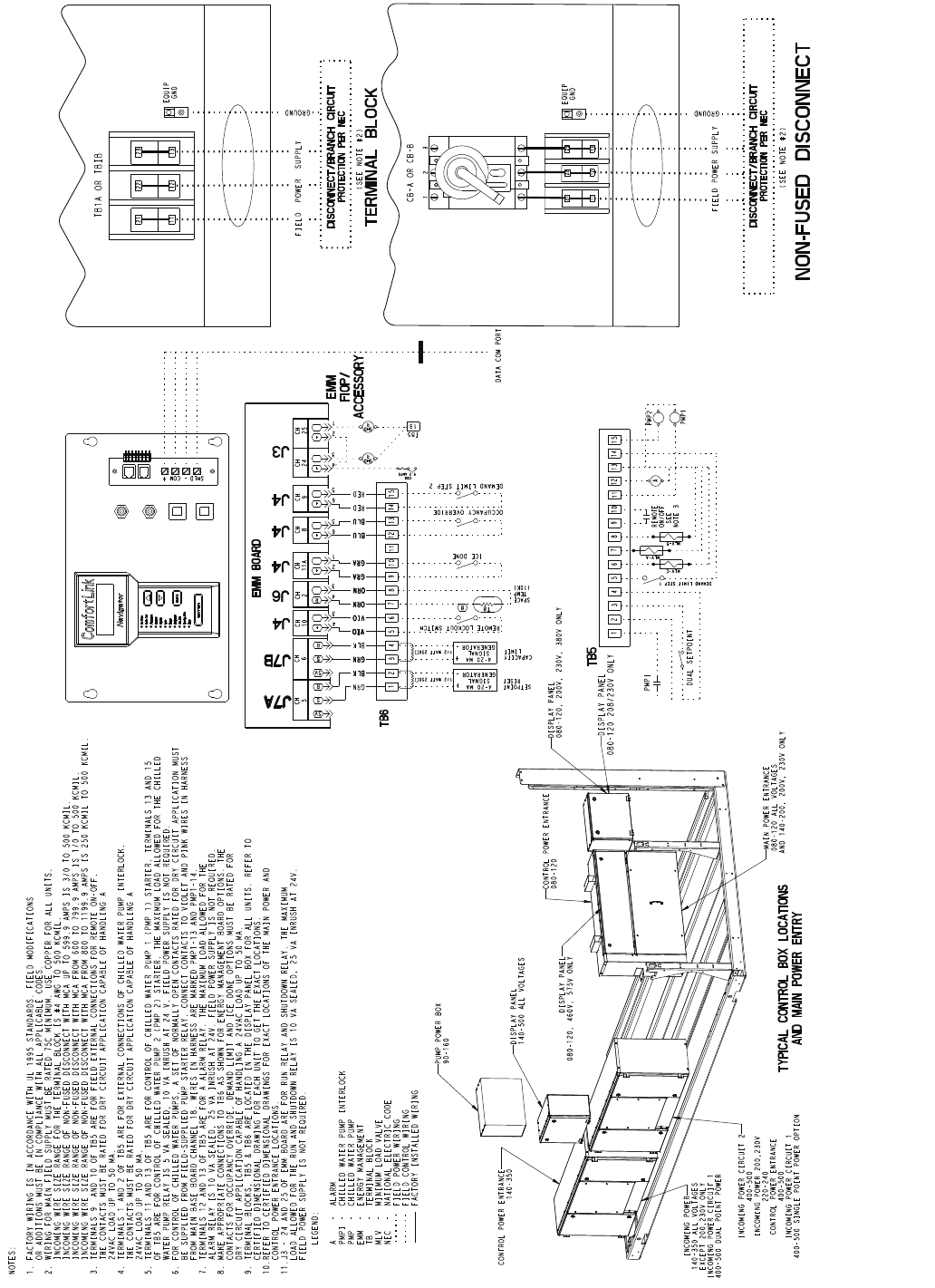
63
ICE DONE
DEMAND LIMIT STEP 2
OCCUPANCY OVERRIDE
DUAL SETPOINT
12 345678910 11 12 13 14 15
TB5
TB6 12 345678910 11 12 13 14 15
EMM
FIOP/
ACCESSORY
REMOTE
ON/OFF
SEE
NOTE 3
A
+
COM
-
SHLD
DATA COM PORT
TERMINAL BLOCK
FIELD POWER SUPPLY
GROUND
(SEE NOTE #2)
21
11
DISCONNECT/BRANCH CIRCUIT
PROTECTION PER NEC
22
12
23
13
EQUIP
GND
TB1A OR TBIB
LEGEND:
A - ALARM
PMPI - CHILLED WATER PUMP INTERLOCK
PMP - CHILLED WATER PUMP
EMM - ENERGY MANAGEMENT
TB - TERMINAL BLOCK
MLV - MINIMUM LOAD VALVE
NEC - NATIONAL ELECTRIC CODE
FIELD POWER WIRING
FIELD CONTROL WIRING
FACTORY INSTALLED WIRING
NOTES:
1. FACTORY WIRING IS IN ACCORDANCE WITH UL 1995 STANDARDS. FIELD MODIFICATIONS
OR ADDITIONS MUST BE IN COMPLIANCE WITH ALL APPLICABLE CODES.
2. WIRING FOR MAIN FIELD SUPPLY MUST BE RATED 75C MINIMUM. USE COPPER FOR ALL UNITS.
INCOMING WIRE SIZE RANGE FOR THE TERMINAL BLOCK IS #4 AWG TO 500 KCMIL.
INCOMING WIRE SIZE RANGE OF NON-FUSED DISCONNECT WITH MCA UP TO 599.9 AMPS IS 3/0 TO 500 KCMIL.
INCOMING WIRE SIZE RANGE OF NON-FUSED DISCONNECT WITH MCA FROM 600 TO 799.9 AMPS IS 1/0 TO 500 KCMIL.
INCOMING WIRE SIZE RANGE OF NON-FUSED DISCONNECT WITH MCA FROM 800 TO 1199.9 AMPS IS 250 KCMIL TO 500 KCMIL.
3. TERMINALS 9 AND 10 OF TB5 ARE FOR FIELD EXTERNAL CONNECTIONS FOR REMOTE ON-OFF.
THE CONTACTS MUST BE RATED FOR DRY CIRCUIT APPLICATION CAPABLE OF HANDLING A
24VAC LOAD UP TO 50 MA.
4. TERMINALS 1 AND 2 OF TB5 ARE FOR EXTERNAL CONNECTIONS OF CHILLED WATER PUMP INTERLOCK.
THE CONTACTS MUST BE RATED FOR DRY CIRCUIT APPLICATION CAPABLE OF HANDLING A
24VAC LOAD UP TO 50 MA.
5. TERMINALS 11 AND 13 OF TB5 ARE FOR CONTROL OF CHILLED WATER PUMP 1 (PMP 1) STARTER. TERMINALS 13 AND 15
OF TB5 ARE FOR CONTROL OF CHILLED WATER PUMP 2 (PMP 2) STARTER. THE MAXIMUM LOAD ALLOWED FOR THE CHILLED
WATER PUMP RELAY IS 5 VA SEALED, 10 VA INRUSH AT 24 V. FIELD POWER SUPPLY IS NOT REQUIRED.
6. FOR CONTROL OF CHILLED WATER PUMPS, A SET OF NORMALLY OPEN CONTACTS RATED FOR DRY CIRCUIT APPLICATION MUST
BE SUPPLIED FROM FIELD-SUPPLIED PUMP STARTER RELAY. CONNECT CONTACTS TO VIOLET AND PINK WIRES IN HARNESS
FROM MAIN BASE BOARD CHANNEL 18. WIRES IN HARNESS ARE MARKED PMP1-13 AND PMP1-14.
7. TERMINALS 12 AND 13 OF TB5 ARE FOR A ALARM RELAY. THE MAXIMUM LOAD ALLOWED FOR THE
ALARM RELAY IS 10 VA SEALED, 25 VA INRUSH AT 24V. FIELD POWER SUPPLY IS NOT REQUIRED.
8. MAKE APPROPRIATE CONNECTIONS TO TB6 AS SHOWN FOR ENERGY MANAGEMENT BOARD OPTIONS. THE
CONTACTS FOR OCCUPANCY OVERRIDE, DEMAND LIMIT AND ICE DONE OPTIONS MUST BE RATED FOR
DRY CIRCUIT APPLICATION CAPABLE OF HANDLING A 24VAC LOAD UP TO 50 MA.
9. TERMINAL BLOCKS, TB5 & TB6 ARE LOCATED IN THE DISPLAY PANEL BOX FOR ALL UNITS. REFER TO
CERTIFIED DIMENSIONAL DRAWING FOR EACH UNIT TO GET THE EXACT LOCATIONS.
10.REFER TO CERTIFIED DIMENSIONAL DRAWINGS FOR EXACT LOCATIONS OF THE MAIN POWER AND
CONTROL POWER ENTRANCE LOCATIONS.
11.J3 - 24 AND 25 OF EMM BOARD ARE FOR RUN RELAY AND SHUTDOWN RELAY. THE MAXIMUM
LOAD ALLOWED FOR THE RUN AND SHUTDOWN RELAY IS 10 VA SEALED, 25 VA INRUSH AT 24V.
FIELD POWER SUPPLY IS NOT REQUIRED.
NON-FUSED DISCONNECT
FIELD POWER SUPPLY
GROUND
(SEE NOTE #2)
DISCONNECT/BRANCH CIRCUIT
PROTECTION PER NEC
EQUIP
GND
CB-A OR CB-B
123
PMPI
CAPACITY
LIMIT
SETPOINT
RESET
8
T8
SPACE
TEMP
(10K) J6
R
4
3
CH
2
J4
+
2
1
CH
11A
J4
+
6
5
CH
8
J4
+
6
5
CH
9
EMM BOARD
DEMAND LIMIT STEP 1
4-20 MA
SIGNAL
GENERATOR
4-20 MA
SIGNAL
GENERATOR
+
-
GRN
BLK
REMOTE LOCKOUT SWITCH J4
+
4
3
CH
10
1/2 WATT 250
TYPICAL CONTROL BOX LOCATIONS
AND MAIN POWER ENTRY
BLK
GRN
VIO
VIO
ORN
ORN
GRA
GRA
BLU
BLU
RED
RED
J7B
CH
6
J7A
CH
5
R
S
5V
R
S
5V
DISPLAY PANEL
080-120, 200V, 230V, 380V ONLY
DISPLAY PANEL
080-120, 460V, 575V ONLY
DISPLAY PANEL
140-500 ALL VOLTAGES
INCOMING POWER
140-350 ALL VOLTAGES
EXCEPT 200,230V ONLY
INCOMING POWER CIRCUIT 1
400-500 DUAL POINT POWER
INCOMING POWER CIRCUIT 2
400-500
INCOMING POWER 200,230V
220-240
CONTROL POWER ENTRANCE
400-500
INCOMING POWER CIRCUIT 1
400-500 SINGLE POINT POWER OPTION
MAIN POWER ENTRANCE
080-120 ALL VOLTAGES
AND 140-200, 200V, 230V ONLY
CONTROL POWER ENTRANCE
080-120
CONTROL POWER ENTRANCE
140-350
PUMP POWER BOX
90-160
PMP1
PMP2
MLV-C
MLV-A
MLV-B
21
11
22
12
23
13
SJ7B
J7A
GRA
GRA
BLU
BLU
ORN
ORN
VIO
GRN
VIO
BLK
+
-
1/2 WATT 250
GRA
GRA
BLU
BLU
ORN
ORN
VIO
GRN
VIO
BLK
DISPLAY PANEL
080-120 208/230V ONLY
J3
+
4
3
CH
24
+
2
1
CH
25
R
SHD
R
SHD
13
TB5
3.2 AMPS
CB8
Fig. 37 — Control and Power Wiring Schematic

64
Table 5 — 30XA080-500 Electrical Data, Single Point (Standard Condenser Fan Motors)
LEGEND
NOTES:
1. Units are suitable for use on electrical systems where voltage supplied to the unit ter-
minals is not below or above the listed minimum and maximum limits. Maximum allow-
able phase imbalance is: voltage, 2%; amps 10%.
2. Cooler heater is wired into the control circuit so it is always operable as long as the
control power supply disconnect is on, even if any safety device is open.
3. For MCA that is less than or equal to 380 amps, 3 conductors are required.
For MCA between 381-760 amps, 6 conductors are required.
For MCA between 761-1140 amps, 9 conductors are required.
For MCA between 1141-1520 amps, 12 conductors are required.
Calculation of conductors required is based on 75 C copper wire.
4. Wiring for main field supply must be rated 75 C minimum. Use copper for all units.
a. Incoming wire size range for the terminal block is no. 4 AWG (American Wire Gage)
to 500 kcmil.
b. Incoming wire size range of non-fused disconnect with MCA up to 599.9 amps is
3/0 to 500 kcmil.
c. Incoming wire size range of non-fused disconnect with MCA from 600 to 799.9 amps
is 1/0 to 500 kcmil.
d. Incoming wire size range of non-fused disconnect with MCA from 800 to 1199.9 amps
is 250 kcmil to 500 kcmil.
5. Data provided circuit 1/circuit 2 where there are two circuits.
UNIT
30XA
UNIT VOLTAGE NUMBER
OF
COND
FANS
NO HYDRONIC PACKAGE 5 HP PUMP, 3450 RPM 7.5 HP PUMP, 3450 RPM CONTROL CIRCUIT
V-Hz
(3 Ph)
Supplied
MCA MOCP
ICF Rec
Fuse
Size
MCA MOCP
ICF Rec
Fuse
Size
MCA MOCP
ICF Rec
Fuse
Size
Vol tage
1 PH,
60 Hz
MCA
and
MOCP
Min Max WD XL WD XL WD XL
080
230-60 207 253 6 315.5 400 484.2 1170.2 350 — — — — — — — — — — 115 40
200-60 187 220 6 347.6 450 549.6 1338.6 400 — — — — — — — — — — 115 40
460-60 414 506 6 157.7 200 242.1 585.1 175 — — — — — — — — — — 115 40
575-60 518633 6 121.2 150 191.9 465.9 150 — — — — — — — — — — 115 40
380-60 342 4186183.5 250 289.7 704.7 225 — — — — — — — — — — 115 40
090
230-60 207 253 8334.0 450 499.1 1185.1 400 350.0 450 515.1 1201.1 400 357.2 450 522.3 1208.3 400 115 40
200-60 187220 8368.0 500 566.0 1355.0 450 385.7 500 583.7 1372.7 450 393.6 500 591.7 1380.7 450 115 40
460-60 414 506 8167.0 225 249.6 592.6 200 175.0 225 257.6 600.6 200 178.6 225 261.2 604.2 200 115 40
575-60 518633 8128.5 175 197.8471.8150 134.9 175 204.2 478.2 150 137.7 175 207.0 481.0 150 115 40
380-60 342 4188194.5 250 298.6 713.6 225 204.2 250 308.3 723.3 225 208.6 250 312.6 727.6 250 115 40
100
230-60 207 253 8364.6 500 536.7 1278.7 400 380.6 500 552.7 1294.7 450 387.8500 559.9 1301.9 450 115 40
200-60 187220 8401.3 500 607.81461.8450 419.0 500 625.5 1479.5 500 427.0 500 633.5 1487.5 500 115 40
460-60 414 506 8182.3 250 268.4 639.4 200 190.3 250 276.4 647.4 225 193.9 250 280.0 651.0 225 115 40
575-60 518633 8139.5 175 211.7 508.7 175 145.9 175 218.1 515.1 175 148.8200 220.9 517.9 175 115 40
380-60 342 4188212.7 250 321.7 770.7 250 222.4 300 331.3 780.3 250 226.7 300 335.7 784.7 250 115 40
110
230-60 207 253 8405.7 500 536.7 — 450 421.7 500 552.7 — 500 428.9 600 559.9 — 500 115 40
200-60 187220 8446.2 600 607.8— 500 463.9 600 625.5 — 600 471.9 600 633.5 — 600 115 40
460-60 414 506 8202.4 250 268.4 639.4 225 210.4 250 276.4 647.4 250 214.0 300 280.0 651.0 250 115 40
575-60 518633 8155.5 200 211.7 508.7 175 161.9 225 218.1 515.1 200 164.8225 220.9 517.9 200 115 40
380-60 342 4188236.4 300 321.7 770.7 300 246.1 300 331.3 780.3 300 250.4 350 335.7 784.7 300 115 40
120
230-60 207 253 8438.6 600 569.6 — 500 454.6 600 585.6 — 500 461.8600 592.8—600 115 40
200-60 187220 8482.2 600 643.8— 600 499.9 600 661.5 — 600 507.8600 669.4 — 600 115 40
460-60 414 506 8218.4 300 284.4 655.4 250 226.4 300 292.4 663.4 250 230.0 300 296.0 667.0 300 115 40
575-60 518633 8168.4 225 224.5 521.5 200 174.8225 230.9 527.9 200 177.7 225 233.8530.8200 115 40
380-60 342 4188255.3 350 340.6 789.6 300 265.0 350 350.3 799.3 300 269.4 350 354.7 803.7 300 115 40
140
230-60 207 253 10 534.7 800 796.7 — 700 550.7 800 812.7 — 700 557.9 800 819.9 — 700 115 40
200-60 187 220 10 588.5 800 906.1 — 700 606.2 800 923.8— 700 614.1 800 931.8—700 115 40
460-60 414 506 10 267.3 400 398.4 1030.4 350 275.3 400 406.4 1038.4 350 278.9 400 410.0 1042.0 350 115 40
575-60 518633 10 205.0 300 315.5 821.5 250 211.4 300 321.9 827.9 250 214.3 300 324.7 830.7 250 115 40
380-60 342 41810 311.2 450 478.9 1243.9 350 320.9 450 488.6 1253.6 400 325.3 450 493.0 1258.0 400 115 40
160
230-60 207 253 10 621.1 800 997.6 — 700 637.1 800 1013.6 — 800 644.3 800 1020.8—800 115 40
200-60 187 220 10 682.81000 1136.1 — 800 700.5 1000 1153.8—800 708.5 1000 1161.7 — 800 115 40
460-60 414 506 10 309.7 450 498.4 1306.4 350 317.7 450 506.4 1314.4 400 321.3 450 510.0 1318.0 400 115 40
575-60 518633 10 238.1 350 396.3 1042.3 300 244.5 350 402.7 1048.7 300 247.4 350 405.6 1051.6 300 115 40
380-60 342 41810 361.1 500 598.9 1577.9 450 370.8500 608.6 1587.6 450 375.2 500 612.9 1591.9 450 115 40
180
230-60 207 253 12 673.2 800 935.2 — 800 — — — — — — — — — — 115 40
200-60 187 220 12 740.9 1000 1058.5 — 1000 — — — — — — — — — — 115 40
460-60 414 506 12 336.6 450 467.6 1099.6 400 — — — — — — — — — — 115 40
575-60 518633 12 258.3 350 368.8874.8300 — — — — — — — — — — 115 40
380-60 342 41812 391.5 500 559.2 1324.2 450 — — — — — — — — — — 115 40
200
230-60 207 253 12 769.6 1000 1146.0 — 1000 — — — — — — — — — — 115 40
200-60 187 220 12 846.0 1000 1299.2 — 1000 — — — — — — — — — — 115 40
460-60 414 506 12 383.9 500 572.6 1380.6 450 — — — — — — — — — — 115 40
575-60 518633 12 294.8400 453.0 1099.0 350 — — — — — — — — — — 115 40
380-60 342 41812 447.2 600 685.0 1664.0 500 — — — — — — — — — — 115 40
220
230-60 207 253 13 850.2 1200 1152.0 — 1000 — — — — — — — — — — 115 40
200-60 187 220 13 935.1 1200 1305.9 — 1200 — — — — — — — — — — 115 40
460-60 414 506 13 424.7 600 575.6 1383.6 500 — — — — — — — — — — 115 40
575-60 518633 13 326.3 450 455.4 1101.4 400 — — — — — — — — — — 115 40
380-60 342 41813 494.5 700 688.6 1667.6 600 — — — — — — — — — — 115 40
240
230-60 207 253 13 910.0 1200 1211.8— 1200 — — — — — — — — — — 115 40
200-60 187 220 13 1001.1 1200 1371.8— 1200 — — — — — — — — — — 115 40
460-60 414 506 13 455.0 600 605.9 1413.9 600 — — — — — — — — — — 115 40
575-60 518633 13 349.6 450 478.7 1124.7 400 — — — — — — — — — — 115 40
380-60 342 41813 529.5 700 723.5 1702.5 600 — — — — — — — — — — 115 40
260
460-60 414 506 15 516.5 700 777.6 1999.6 600 — — — — — — — — — — 115 40
575-60 518633 15 396.4 500 616.2 1594.2 450 — — — — — — — — — — 115 40
380-60 342 41815 600.2 800 933.9 2412.9 700 — — — — — — — — — — 115 40
280
460-60 414 506 16 549.7 800 810.9 2032.9 700 — — — — — — — — — — 115 40
575-60 518633 16 422.1 600 641.9 1619.9 500 — — — — — — — — — — 115 40
380-60 342 41816 638.7 800 972.4 2451.4 800 — — — — — — — — — — 115 40
300
460-60 414 506 16 610.9 800 810.9 2032.9 700 — — — — — — — — — — 115 40
575-60 518633 16 468.7 600 641.9 1619.9 600 — — — — — — — — — — 115 40
380-60 342 41816 710.3 1000 972.4 2451.4 800 — — — — — — — — — — 115 40
325
460-60 414 506 18624.3 800 885.5 2107.5 700 — — — — — — — — — — 115 40
575-60 518633 18479.1 600 698.9 1676.9 600 — — — — — — — — — — 115 40
380-60 342 41818724.7 1000 1058.4 2537.4 800 — — — — — — — — — — 115 40
350
460-60 414 506 18685.5 800 885.5 2107.5 800 — — — — — — — — — — 115 40
575-60 518633 18525.7 700 698.9 1676.9 600 — — — — — — — — — — 115 40
380-60 342 41818796.3 1000 1058.4 2537.4 1000 — — — — — — — — — — 115 40
400
460-60 414 506 20 746.6 1000 1007.82229.81000 — — — — — — — — — — 115 50
575-60 518633 20 573.2 700 793.1 1771.1 700 — — — — — — — — — — 115 50
380-60 342 41820 867.6 1000 1201.3 2680.3 1000 — — — — — — — — — — 115 50
450
460-60 414 506 22 880.0 1000 1080.0 2302.0 1000 — — — — — — — — — — 115 50
575-60 518633 22 674.6 800 847.81825.8800 — — — — — — — — — — 115 50
380-60 342 41822 1022.7 1200 1284.82763.81200 — — — — — — — — — — 115 50
500
460-60 414 506 22 931.3 1200 1131.3 2353.3 1200 — — — — — — — — — — 115 50
575-60 518633 22 714.1 800 887.3 1865.3 800 — — — — — — — — — — 115 50
380-60 342 41822 1082.4 1200 1344.5 2823.5 1200 — — — — — — — — — — 115 50
ICF — Instantaneous Current Flow
MCA — Minimum Circuit Amps
MOCP — Maximum Overcurrent Protection
WD — Wye-Delta
XL — Across-the-Line

65
Table 5 — 30XA080-500 Electrical Data, Single Point (Standard Condenser Fan Motors) (cont)
LEGEND
NOTES:
1. Units are suitable for use on electrical systems where voltage supplied to the unit ter-
minals is not below or above the listed minimum and maximum limits. Maximum allow-
able phase imbalance is: voltage, 2%; amps 10%.
2. Cooler heater is wired into the control circuit so it is always operable as long as the
control power supply disconnect is on, even if any safety device is open.
3. For MCA that is less than or equal to 380 amps, 3 conductors are required.
For MCA between 381-760 amps, 6 conductors are required.
For MCA between 761-1140 amps, 9 conductors are required.
For MCA between 1141-1520 amps, 12 conductors are required.
Calculation of conductors required is based on 75 C copper wire.
4. Wiring for main field supply must be rated 75 C minimum. Use copper for all units.
a. Incoming wire size range for the terminal block is no. 4 AWG (American Wire Gage)
to 500 kcmil.
b. Incoming wire size range of non-fused disconnect with MCA up to 599.9 amps is
3/0 to 500 kcmil.
c. Incoming wire size range of non-fused disconnect with MCA from 600 to 799.9 amps
is 1/0 to 500 kcmil.
d. Incoming wire size range of non-fused disconnect with MCA from 800 to 1199.9 amps
is 250 kcmil to 500 kcmil.
5. Data provided circuit 1/circuit 2 where there are two circuits.
UNIT
30XA
UNIT VOLTAGE NUMBER
OF
COND
FANS
10 HP PUMP, 3450 RPM 15 HP PUMP, 3450 RPM CONTROL CIRCUIT
V-Hz
(3 Ph)
Supplied
MCA MOCP
ICF Rec
Fuse
Size
MCA MOCP
ICF Rec
Fuse
Size
Vol tage
1 PH,
60 Hz
MCA
and
MOCP
Min Max WD XL WD XL
080
230-60 207 253 6 — — — — — — — — — — 115 40
200-60 187 220 6 — — — — — — — — — — 115 40
460-60 414 506 6 — — — — — — — — — — 115 40
575-60 518633 6 — — — — — — — — — — 115 40
380-60 342 4186——————————115 40
090
230-60 207 253 8364.4 450 529.5 1215.5 400 379.0 500 544.1 1230.1 450 115 40
200-60 187220 8401.6 500 599.6 1388.6 450 417.7 500 615.81404.8500 115 40
460-60 414 506 8182.2 225 264.8607.8200 189.5 250 272.1 615.1 225 115 40
575-60 518633 8140.6 175 209.9 483.9 175 146.5 175 215.8489.8175 115 40
380-60 342 4188212.9 250 317.0 732.0 250 221.8250 325.8740.8250 115 40
100
230-60 207 253 8395.0 500 567.1 1309.1 450 409.6 500 581.7 1323.7 450 115 40
200-60 187220 8434.9 500 641.5 1495.5 500 451.1 600 657.6 1511.6 500 115 40
460-60 414 506 8197.5 250 283.6 654.6 225 204.8250 290.9 661.9 225 115 40
575-60 518633 8151.7 200 223.8520.8175 157.5 200 229.7 526.7 175 115 40
380-60 342 4188231.1 300 340.1 789.1 300 239.9 300 348.9 797.9 300 115 40
110
230-60 207 253 8436.1 600 567.1 — 500 450.7 600 581.7 — 500 115 40
200-60 187220 8479.9 600 641.5 — 600 496.0 600 657.6 — 600 115 40
460-60 414 506 8217.6 300 283.6 654.6 250 224.9 300 290.9 661.9 250 115 40
575-60 518633 8167.7 225 223.8520.8200 173.5 225 229.7 526.7 200 115 40
380-60 342 4188254.8350 340.1 789.1 300 263.6 350 348.9 797.9 300 115 40
120
230-60 207 253 8469.0 600 600.0 — 600 483.6 600 614.6 — 600 115 40
200-60 187220 8515.8700 677.4 — 600 531.9 700 693.5 — 600 115 40
460-60 414 506 8233.6 300 299.6 670.6 300 240.9 300 306.9 677.9 300 115 40
575-60 518633 8180.5 225 236.7 533.7 200 186.4 250 242.5 539.5 225 115 40
380-60 342 4188273.7 350 359.0 808.0 300 282.6 350 367.9 816.9 350 115 40
140
230-60 207 253 10 565.1 800 827.1 — 700 579.7 800 841.7 — 700 115 40
200-60 187 220 10 622.1 800 939.7 — 700 638.2 800 955.9 — 800 115 40
460-60 414 506 10 282.5 400 413.6 1045.6 350 289.8400 420.9 1052.9 350 115 40
575-60 518633 10 217.1 300 327.6 833.6 250 223.0 300 333.5 839.5 250 115 40
380-60 342 41810 329.6 450 497.3 1262.3 400 338.5 450 506.2 1271.2 400 115 40
160
230-60 207 253 10 651.5 800 1028.0 — 800 666.1 800 1042.6 — 800 115 40
200-60 187 220 10 716.4 1000 1169.7 — 1000 732.6 1000 1185.8— 1000 115 40
460-60 414 506 10 324.9 450 513.6 1321.6 400 332.2 450 520.9 1328.9 400 115 40
575-60 518633 10 250.2 350 408.5 1054.5 300 256.1 350 414.3 1060.3 300 115 40
380-60 342 41810 379.5 500 617.3 1596.3 450 388.4 500 626.1 1605.1 450 115 40
180
230-60 207 253 12 — — — — — — — — — — 115 40
200-60 187 220 12 — — — — — — — — — — 115 40
460-60 414 506 12 — — — — — — — — — — 115 40
575-60 518633 12 — — — — — — — — — — 115 40
380-60 342 41812 — — — — — — — — — — 115 40
200
230-60 207 253 12 — — — — — — — — — — 115 40
200-60 187 220 12 — — — — — — — — — — 115 40
460-60 414 506 12 — — — — — — — — — — 115 40
575-60 518633 12 — — — — — — — — — — 115 40
380-60 342 41812 — — — — — — — — — — 115 40
220
230-60 207 253 13 — — — — — — — — — — 115 40
200-60 187 220 13 — — — — — — — — — — 115 40
460-60 414 506 13 — — — — — — — — — — 115 40
575-60 518633 13 — — — — — — — — — — 115 40
380-60 342 41813 — — — — — — — — — — 115 40
240
230-60 207 253 13 — — — — — — — — — — 115 40
200-60 187 220 13 — — — — — — — — — — 115 40
460-60 414 506 13 — — — — — — — — — — 115 40
575-60 518633 13 — — — — — — — — — — 115 40
380-60 342 41813 — — — — — — — — — — 115 40
260
460-60 414 506 15 — — — — — — — — — — 115 40
575-60 518633 15 — — — — — — — — — — 115 40
380-60 342 41815 — — — — — — — — — — 115 40
280
460-60 414 506 16 — — — — — — — — — — 115 40
575-60 518633 16 — — — — — — — — — — 115 40
380-60 342 41816 — — — — — — — — — — 115 40
300
460-60 414 506 16 — — — — — — — — — — 115 40
575-60 518633 16 — — — — — — — — — — 115 40
380-60 342 41816 — — — — — — — — — — 115 40
325
460-60 414 506 18—— — ———— — —— 115 40
575-60 518633 18—— — ———— — —— 115 40
380-60 342 41818—— — ———— — —— 115 40
350
460-60 414 506 18—— — ———— — —— 115 40
575-60 518633 18—— — ———— — —— 115 40
380-60 342 41818—— — ———— — —— 115 40
400
460-60 414 506 20 — — — — — — — — — — 115 50
575-60 518633 20 — — — — — — — — — — 115 50
380-60 342 41820 — — — — — — — — — — 115 50
450
460-60 414 506 22 — — — — — — — — — — 115 50
575-60 518633 22 — — — — — — — — — — 115 50
380-60 342 41822 — — — — — — — — — — 115 50
500
460-60 414 506 22 — — — — — — — — — — 115 50
575-60 518633 22 — — — — — — — — — — 115 50
380-60 342 41822 — — — — — — — — — — 115 50
ICF — Instantaneous Current Flow
MCA — Minimum Circuit Amps
MOCP — Maximum Overcurrent Protection
WD — Wye-Delta
XL — Across-the-Line

66
Table 6 — 30XA080-500 Electrical Data, Dual Point (Standard Condenser Fan Motors)
LEGEND
NOTES:
1. Units are suitable for use on electrical systems where voltage supplied to the unit
terminals is not below or above the listed minimum and maximum limits. Maximum
allowable phase imbalance is: voltage, 2%; amps 10%.
2. Cooler heater is wired into the control circuit so it is always operable as long as the
control power supply disconnect is on, even if any safety device is open.
3. For MCA that is less than or equal to 380 amps, 3 conductors are required.
For MCA between 381-760 amps, 6 conductors are required.
For MCA between 761-1140 amps, 9 conductors are required.
For MCA between 1141-1520 amps, 12 conductors are required.
Calculation of conductors required is based on 75 C copper wire.
4. Wiring for main field supply must be rated 75 C minimum. Use copper for all units.
a. Incoming wire size range for the terminal block is no. 4 AWG (American Wire Gage)
to 500 kcmil.
b. Incoming wire size range of non-fused disconnect with MCA up to 599.9 amps is
3/0 to 500 kcmil.
c. Incoming wire size range of non-fused disconnect with MCA from 600 to 799.9 amps
is 1/0 to 500 kcmil.
d. Incoming wire size range of non-fused disconnect with MCA from 800 to 1199.9 amps
is 250 kcmil to 500 kcmil.
5. Data provided circuit 1/circuit 2 where there are two circuits.
UNIT
30XA
UNIT VOLTAGE NUMBER
OF
COND
FANS
NO HYDRONIC PACKAGE 5 HP PUMP, 3450 RPM CONTROL CIRCUIT
V-Hz
(3 Ph)
Supplied
MCA MOCP
ICF Rec
Fuse
Size
MCA MOCP
ICF Rec
Fuse
Size
Voltag e
1 PH,
60 Hz
MCA
and
MOCP
Min Max WD XL WD XL
080
230-60 207 253 3/3 173.3/173.3 250/ 250 342.0/342.0 1028.0/1028.0 225/225 — — — — — 115 40
200-60 187 220 3/3 190.9/190.9 300/ 300 392.9/392.9 1181.9/1181.9 250/250 — — — — — 115 40
460-60 414 506 3/3 86.6/ 86.6 125/ 125 171.0/171.0 514.0/ 514.0 110/110 — — — — — 115 40
575-60 518633 3/3 66.5/ 66.5 110/ 110 137.2/137.2 411.2/ 411.2 80/ 80— — — — — 115 40
380-60 342 4183/3 100.7/100.7 150/ 150 206.9/206.9 621.9/ 621.9 125/125 — — — — — 115 40
090
230-60 207 253 4/4 182.9/182.9 300/ 300 348.0/348.0 1034.0/1034.0 225/225 182.9/198.9 300/300 348.0/364.0 1034.0/1050.0 225/250 115 40
200-60 187 220 4/4 201.5/201.5 300/ 300 399.5/399.5 1188.5/1188.5 250/250 201.5/219.2 300/350 399.5/417.2 1188.5/1206.2 250/300 115 40
460-60 414 506 4/4 91.4/ 91.4 150/ 150 174.0/174.0 517.0/ 517.0 110/110 91.4/ 99.4 150/150 174.0/182.0 517.0/ 525.0 110/125 115 40
575-60 518633 4/4 70.3/ 70.3 110/ 110 139.6/139.6 413.6/ 413.6 90/ 90 70.3/ 76.7 110/125 139.6/146.0 413.6/ 420.0 90/ 90 115 40
380-60 342 4184/4 106.5/106.5 175/ 175 210.5/210.5 625.5/ 625.5 125/125 106.5/116.1 175/175 210.5/220.2 625.5/ 635.2 125/150 115 40
100
230-60 207 253 4/4 199.9/199.9 300/ 300 372.0/372.0 1114.0/1114.0 250/250 199.9/215.9 300/350 372.0/388.0 1114.0/1130.0 250/300 115 40
200-60 187 220 4/4 220.0/220.0 350/ 350 426.5/426.5 1280.5/1280.5 300/300 220.0/237.7 350/350 426.5/444.2 1280.5/1298.2 300/300 115 40
460-60 414 506 4/4 99.9/ 99.9 150/ 150 186.0/186.0 557.0/ 557.0 125/125 99.9/107.9 150/175 186.0/194.0 557.0/ 565.0 125/150 115 40
575-60 518633 4/4 76.4/ 76.4 125/ 125 148.6/148.6 445.6/ 445.6 90/ 90 76.4/ 82.8125/125 148.6/155.0 445.6/ 452.0 90/100 115 40
380-60 342 4184/4 116.5/116.5 175/ 175 225.5/225.5 674.5/ 674.5 150/150 116.5/126.2 175/200 225.5/235.2 674.5/ 684.2 150/150 115 40
110
230-60 207 253 4/4 241.0/199.9 400/ 300 372.0/372.0 — 300/250 241.0/215.9 400/350 372.0 /388.0 — 300/300 115 40
200-60 187 220 4/4 264.9/220.0 450/ 350 426.5/426.5 — 350/300 264.9/237.7 450/350 426.5/444.2 — 350/300 115 40
460-60 414 506 4/4 120.0/ 99.9 200/ 150 186.0/186.0 557.0/557.0 150/125 120.0/107.9 200/175 186.0/194.0 557.0/ 565.0 150/150 115 40
575-60 518633 4/4 92.5/ 76.4 150/ 125 148.6/148.6 445.6/445.6 110/ 90 92.5/ 82.8150/125 148.6/155.0 445.6/ 452.0 110/100 115 40
380-60 342 4184/4 140.2/116.5 225/ 175 225.5/225.5 674.5/674.5 175/150 140.2/126.2 225/200 225.5/235.2 674.5/ 684.2 175/150 115 40
120
230-60 207 253 4/4 241.0/241.0 400/ 400 372.0/372.0 — 300/300 241.0/257.0 400/400 372.0/388.0 — 300/350 115 40
200-60 187 220 4/4 264.9/264.9 450/ 450 426.5/426.5 — 350/350 264.9/282.6 450/450 426.5/444.2 — 350/350 115 40
460-60 414 506 4/4 120.0/120.0 200/ 200 186.0/186.0 557.0/557.0 150/150 120.0/128.0 200/200 186.0/194.0 557.0/ 565.0 150/150 115 40
575-60 518633 4/4 92.5/ 92.5 150/ 150 148.6/148.6 445.6/445.6 110/110 92.5/ 98.9 150/150 148.6/155.0 445.6/ 452.0 110/125 115 40
380-60 342 4184/4 140.2/140.2 225/ 225 225.5/225.5 674.5/674.5 175/175 140.2/149.9 225/250 225.5/235.2 674.5/ 684.2 175/200 115 40
140
230-60 207 253 6/4 370.0/199.9 600/ 300 632.0/372.0 — 450/250 370.0/215.9 600/350 632.0/388.0 — 450/300 115 40
200-60 187 220 6/4 407.2/220.0 700/ 350 724.8/426.5 — 500/300 407.2/237.7 700/350 724.8/444.2 — 500/300 115 40
460-60 414 506 6/4 185.0/ 99.9 300/ 150 316.0/186.0 948.0/557.0 225/125 185.0/107.9 300/175 316.0/194.0 948.0/ 565.0 225/150 115 40
575-60 518633 6/4 141.9/ 76.4 225/ 125 252.4/148.6 758.4/445.6 175/ 90 141.9/ 82.8225/125 252.4/155.0 758.4/ 452.0 175/100 115 40
380-60 342 4186/4 215.1/116.5 350/ 175 382.8/225.5 1147.8/674.5 300/150 215.1/126.2 350/200 382.8/235.2 1147.8/684.2 300/150 115 40
160
230-60 207 253 6/4 423.5/241.0 700/ 400 800.0/372.0 — 600/300 423.5/257.0 700/400 800.0/388.0 — 600/350 115 40
200-60 187 220 6/4 465.6/264.9 800/ 450 918.8/426.5 — 600/350 465.6/282.6 800/450 918.8/444.2 — 600/350 115 40
460-60 414 506 6/4 211.3/120.0 350/ 200 400.0/186.0 1208.0/557.0 250/150 211.3/128.0 350/200 400.0/194.0 1208.0/ 565.0 250/150 115 40
575-60 518633 6/4 162.2/ 92.5 250/ 150 320.4/148.6 966.4/445.6 200/110 162.2/ 98.9 250/150 320.4/155.0 966.4/ 452.0 200/125 115 40
380-60 342 4186/4 246.0/140.2 400/ 225 483.8/225.5 1462.8/674.5 300/175 246.0/149.9 400/250 483.8/235.2 1462.8/684.2 300/200 115 40
180
230-60 207 253 6/6 370.0/370.0 600/ 600 632.0/632.0 — 450/450 — — — — — 115 40
200-60 187 220 6/6 407.2/407.2 700/ 700 724.8/724.8— 500/500 — — — — — 115 40
460-60 414 506 6/6 185.0/185.0 300/ 300 316.0/316.0 948.0/ 948.0 225/225 — — — — — 115 40
575-60 518633 6/6 141.9/141.9 225/ 225 252.4/252.4 758.4/ 758.4 175/175 — — — — — 115 40
380-60 342 4186/6 215.1/215.1 350/ 350 382.8/382.81147.8/1147.8300/300 — — — — — 115 40
200
230-60 207 253 6/6 423.5/423.5 700/ 700 800.0/800.0 — 600/600 — — — — — 115 40
200-60 187 220 6/6 465.6/465.6 800/ 800 918.8/918.8— 600/600 — — — — — 115 40
460-60 414 506 6/6 211.3/211.3 350/ 350 400.0/400.0 1208.0/1208.0 250/250 — — — — — 115 40
575-60 518633 6/6 162.2/162.2 250/ 250 320.4/320.4 966.4/ 966.4 200/200 — — — — — 115 40
380-60 342 4186/6 246.0/246.0 400/ 400 483.8/483.81462.8/1462.8300/300 — — — — — 115 40
220
230-60 207 253 7/6 504.2/423.5 800/ 700 806.0/800.0 — 600/600 — — — — — 115 40
200-60 187 220 7/6 554.7/465.6 800/ 800 925.4/918.8— 700/600 — — — — — 115 40
460-60 414 506 7/6 252.1/211.3 400/ 350 403.0/400.0 1211.0/1208.0 300/250 — — — — — 115 40
575-60 518633 7/6 193.7/162.2 300/ 250 322.8/320.4 968.8/ 966.4 250/200 — — — — — 115 40
380-60 342 4187/6 293.3/246.0 500/ 400 487.4/483.81466.4/1462.8350/300 — — — — — 115 40
240
230-60 207 253 7/6 504.2/498.2 800/ 800 806.0/800.0 — 600/600 — — — — — 115 40
200-60 187 220 7/6 554.7/548.0 800/ 800 925.4/918.8— 700/700 — — — — — 115 40
460-60 414 506 7/6 252.1/249.1 400/ 400 403.0/400.0 1211.0/1208.0 300/300 — — — — — 115 40
575-60 518633 7/6 193.7/191.3 300/ 300 322.8/320.4 968.8/ 966.4 250/250 — — — — — 115 40
380-60 342 4187/6 293.3/289.7 500/ 500 487.4/483.81466.4/1462.8350/350 — — — — — 115 40
260
460-60 414 506 9/6 343.9/211.3 500/ 350 605.0/400.0 1827.0/1208.0 450/250 — — — — — 115 40
575-60 518633 9/6 263.8/162.2 450/ 250 483.6/320.4 1461.6/ 966.4 350/200 — — — — — 115 40
380-60 342 4189/6 399.0/246.0 600/ 400 732.7/483.82211.7/1462.8500/300 — — — — — 115 40
280
460-60 414 506 9/7 343.9/252.1 500/ 400 605.0/403.0 1827.0/1211.0 450/300 — — — — — 115 40
575-60 518633 9/7 263.8/193.7 450/ 300 483.6/322.81461.6/ 968.8350/250 — — — — — 115 40
380-60 342 4189/7 399.0/293.3 600/ 500 732.7/487.4 2211.7/1466.4 500/350 — — — — — 115 40
300
460-60 414 506 10/6 408.0/249.1 700/ 400 608.0/400.0 1830.0/1208.0 500/300 — — — — — 115 40
575-60 518633 10/6 312.8/191.3 500/ 300 486.0/320.4 1464.0/ 966.4 400/250 — — — — — 115 40
380-60 342 41810/6 474.2/289.7 800/ 500 736.3/483.82215.3/1462.8600/350 — — — — — 115 40
325
460-60 414 506 9/9 343.9/343.9 500/ 500 605.0/605.0 1827.0/1827.0 450/450 — — — — — 115 40
575-60 518633 9/9 263.8/263.8450/ 450 483.6/483.6 1461.6/1461.6 350/350 — — — — — 115 40
380-60 342 4189/9 399.0/399.0 600/ 600 732.7/732.7 2211.7/2211.7 500/500 — — — — — 115 40
350
460-60 414 506 9/9 405.0/343.9 700/ 500 605.0/605.0 1827.0/1827.0 500/450 — — — — — 115 40
575-60 518633 9/9 310.4/263.8500/ 450 483.6/483.6 1461.6/1461.6 400/350 — — — — — 115 40
380-60 342 4189/9 470.5/399.0 800/ 600 732.7/732.7 2211.7/2211.7 600/500 — — — — — 115 40
400
460-60 414 506 8/12 340.9/452.0 500/ 600 602.0/602.9 1824.0/1410.9 450/500 — — — — — 115 50
575-60 518633 8/12 261.4/347.2 450/ 450 481.2/476.3 1459.2/1122.3 350/400 — — — — — 115 50
380-60 342 4188/12 395.4/525.8600/ 700 729.1/719.9 2208.1/1698.9 500/600 — — — — — 115 50
450
460-60 414 506 8/14 402.0/553.6 700/ 800 602.0/753.6 1824.0/1975.6 500/700 — — — — — 115 50
575-60 518633 8/14 308.0/424.4 500/ 600 481.2/597.6 1459.2/1575.6 400/500 — — — — — 115 50
380-60 342 4188/14 466.9/643.3 800/ 800 729.1/905.5 2208.1/2384.5 600/800 — — — — — 115 50
500
460-60 414 506 8/14 402.0/604.9 700/ 800 602.0/804.9 1824.0/2026.9 500/700 — — — — — 115 50
575-60 518633 8/14 308.0/463.9 500/ 600 481.2/637.1 1459.2/1615.1 400/600 — — — — — 115 50
380-60 342 4188/14 466.9/703.0 800/1000 729.1/965.2 2208.1/2444.2 600/800 — — — — — 115 50
ICF — Instantaneous Current Flow
MCA — Minimum Circuit Amps
MOCP — Maximum Overcurrent Protection
WD — Wye-Delta
XL — Across-the-Line

67
Table 6 — 30XA080-500 Electrical Data, Dual Point (Standard Condenser Fan Motors) (cont)
LEGEND
NOTES:
1. Units are suitable for use on electrical systems where voltage supplied to the unit
terminals is not below or above the listed minimum and maximum limits. Maximum
allowable phase imbalance is: voltage, 2%; amps 10%.
2. Cooler heater is wired into the control circuit so it is always operable as long as the
control power supply disconnect is on, even if any safety device is open.
3. For MCA that is less than or equal to 380 amps, 3 conductors are required.
For MCA between 381-760 amps, 6 conductors are required.
For MCA between 761-1140 amps, 9 conductors are required.
For MCA between 1141-1520 amps, 12 conductors are required.
Calculation of conductors required is based on 75 C copper wire.
4. Wiring for main field supply must be rated 75 C minimum. Use copper for all units.
a. Incoming wire size range for the terminal block is no. 4 AWG (American Wire Gage)
to 500 kcmil.
b. Incoming wire size range of non-fused disconnect with MCA up to 599.9 amps is
3/0 to 500 kcmil.
c. Incoming wire size range of non-fused disconnect with MCA from 600 to 799.9 amps
is 1/0 to 500 kcmil.
d. Incoming wire size range of non-fused disconnect with MCA from 800 to 1199.9 amps
is 250 kcmil to 500 kcmil.
5. Data provided circuit 1/circuit 2 where there are two circuits.
UNIT
30XA
UNIT VOLTAGE NUMBER
OF
COND
FANS
7.5 HP PUMP, 3450 RPM 10 HP PUMP, 3450 RPM CONTROL CIRCUIT
V-Hz
(3 Ph)
Supplied
MCA MOCP
ICF Rec
Fuse
Size
MCA MOCP
ICF Rec
Fuse
Size
Voltag e
1 PH,
60 Hz
MCA
and
MOCP
Min Max WD XL WD XL
080
230-60 207 253 3/3 — — — — — — — — — — 115 40
200-60 187 220 3/3 — — — — — — — — — — 115 40
460-60 414 506 3/3 — — — — — — — — — — 115 40
575-60 5186333/3 ——— — ———— — —11540
380-60 342 4183/3 — — — — — — — — — — 115 40
090
230-60 207 253 4/4 182.9/206.1 300/300 348.0/371.2 1034.0/1057.2 225/250 182.9/213.3 300/300 348.0/378.4 1034.0/1064.4 225/250 115 40
200-60 187 220 4/4 201.5/227.1 300/350 399.5/425.2 1188.5/1214.2 250/300 201.5/235.1 300/350 399.5/433.2 1188.5/1222.2 250/300 115 40
460-60 414 506 4/4 91.4/103.0 150/150 174.0/185.6 517.0/ 528.6 110/125 91.4/106.6 150/150 174.0/189.2 517.0/ 532.2 110/125 115 40
575-60 518633 4/4 70.3/ 79.6 110/125 139.6/148.9 413.6/ 422.9 90/100 70.3/ 82.5 110/125 139.6/151.8413.6/ 425.890/100 115 40
380-60 342 4184/4 106.5/120.5 175/175 210.5/224.6 625.5/ 639.6 125/150 106.5/124.9 175/175 210.5/228.9 625.5/ 643.9 125/150 115 40
100
230-60 207 253 4/4 199.9/223.1 300/350 372.0/395.2 1114.0/1137.2 250/300 199.9/230.3 300/350 372.0/402.4 1114.0/1144.4 250/300 115 40
200-60 187 220 4/4 220.0/245.7 350/400 426.5/452.2 1280.5/1306.2 300/300 220.0/253.6 350/400 426.5/460.2 1280.5/1314.2 300/300 115 40
460-60 414 506 4/4 99.9/111.5 150/175 186.0/197.6 557.0/ 568.6 125/150 99.9/115.1 150/175 186.0/201.2 557.0/ 572.2 125/150 115 40
575-60 518633 4/4 76.4/ 85.7 125/125 148.6/157.9 445.6/ 454.9 90/100 76.4/ 88.6 125/125 148.6/160.8445.6/ 457.890/110 115 40
380-60 342 4184/4 116.5/130.6 175/200 225.5/239.6 674.5/ 688.6 150/175 116.5/134.9 175/200 225.5/243.9 674.5/ 692.9 150/175 115 40
110
230-60 207 253 4/4 241.0/223.1 400/350 372.0/395.2 — 300/300 241.0/230.3 400/350 372.0/402.4 — 300/300 115 40
200-60 187 220 4/4 264.9/245.7 450/400 426.5/452.2 — 350/300 264.9/253.6 450/400 426.5/460.2 — 350/300 115 40
460-60 414 506 4/4 120.0/111.5 200/175 186.0/197.6 557.0/ 568.6 150/150 120.0/115.1 200/175 186.0/201.2 557.0/ 572.2 150/150 115 40
575-60 518633 4/4 92.5/ 85.7 150/125 148.6/157.9 445.6/ 454.9 110/100 92.5/ 88.6 150/125 148.6/160.8445.6/ 457.8110/110 115 40
380-60 342 4184/4 140.2/130.6 225/200 225.5/239.6 674.5/ 688.6 175/175 140.2/134.9 225/200 225.5/243.9 674.5/ 692.9 175/175 115 40
120
230-60 207 253 4/4 241.0/264.2 400/400 372.0/395.2 — 300/350 241.0/271.4 400/400 372.0/402.4 — 300/350 115 40
200-60 187 220 4/4 264.9/290.6 450/450 426.5/452.2 — 350/350 264.9/298.5 450/450 426.5/460.2 — 350/350 115 40
460-60 414 506 4/4 120.0/131.6 200/200 186.0/197.6 557.0/ 568.6 150/175 120.0/135.2 200/200 186.0/201.2 557.0/ 572.2 150/175 115 40
575-60 518633 4/4 92.5/101.8150/150 148.6/157.9 445.6/ 454.9 110/125 92.5/104.6 150/150 148.6/160.8445.6/ 457.8110/125 115 40
380-60 342 4184/4 140.2/154.3 225/250 225.5/239.6 674.5/ 688.6 175/200 140.2/158.6 225/250 225.5/243.9 674.5/ 692.9 175/200 115 40
140
230-60 207 253 6/4 370.0/223.1 600/350 632.0/395.2 — 450/300 370.0/230.3 600/350 632.0/402.4 — 450/300 115 40
200-60 187 220 6/4 407.2/245.7 700/400 724.8/452.2 — 500/300 407.2/253.6 700/400 724.8/460.2 — 500/300 115 40
460-60 414 506 6/4 185.0/111.5 300/175 316.0/197.6 948.0/ 568.6 225/150 185.0/115.1 300/175 316.0/201.2 948.0/ 572.2 225/150 115 40
575-60 518633 6/4 141.9/ 85.7 225/125 252.4/157.9 758.4/ 454.9 175/100 141.9/ 88.6 225/125 252.4/160.8758.4/ 457.8175/110 115 40
380-60 342 4186/4 215.1/130.6 350/200 382.8/239.6 1147.8/688.6 300/175 215.1/134.9 350/200 382.8/243.9 1147.8/ 692.9 300/175 115 40
160
230-60 207 253 6/4 423.5/264.2 700/400 800.0/395.2 — 600/350 423.5/271.4 700/400 800.0/402.4 — 600/350 115 40
200-60 187 220 6/4 465.6/290.6 800/450 918.8/452.2 — 600/350 465.6/298.5 800/450 918.8/460.2 — 600/350 115 40
460-60 414 506 6/4 211.3/131.6 350/200 400.0/197.6 1208.0/ 568.6 250/175 211.3/135.2 350/200 400.0/201.2 1208.0/ 572.2 250/175 115 40
575-60 518633 6/4 162.2/101.8250/150 320.4/157.9 966.4/ 454.9 200/125 162.2/104.6 250/150 320.4/160.8966.4/ 457.8200/125 115 40
380-60 342 4186/4 246.0/154.3 400/250 483.8/239.6 1462.8/688.6 300/200 246.0/158.6 400/250 483.8/243.9 1462.8/ 692.9 300/200 115 40
180
230-60 207 253 6/6 — — — — — — — — — — 115 40
200-60 187 220 6/6 — — — — — — — — — — 115 40
460-60 414 506 6/6 — — — — — — — — — — 115 40
575-60 5186336/6 ——— — ———— — —11540
380-60 342 4186/6 — — — — — — — — — — 115 40
200
230-60 207 253 6/6 — — — — — — — — — — 115 40
200-60 187 220 6/6 — — — — — — — — — — 115 40
460-60 414 506 6/6 — — — — — — — — — — 115 40
575-60 5186336/6 ——— — ———— — —11540
380-60 342 4186/6 — — — — — — — — — — 115 40
220
230-60 207 253 7/6 — — — — — — — — — — 115 40
200-60 187 220 7/6 — — — — — — — — — — 115 40
460-60 414 506 7/6 — — — — — — — — — — 115 40
575-60 5186337/6 ——— — ———— — —11540
380-60 342 4187/6 — — — — — — — — — — 115 40
240
230-60 207 253 7/6 — — — — — — — — — — 115 40
200-60 187 220 7/6 — — — — — — — — — — 115 40
460-60 414 506 7/6 — — — — — — — — — — 115 40
575-60 5186337/6 ——— — ———— — —11540
380-60 342 4187/6 — — — — — — — — — — 115 40
260
460-60 414 506 9/6 — — — — — — — — — — 115 40
575-60 5186339/6 ——— — ———— — —11540
380-60 342 4189/6 — — — — — — — — — — 115 40
280
460-60 414 506 9/7 — — — — — — — — — — 115 40
575-60 5186339/7 ——— — ———— — —11540
380-60 342 4189/7 — — — — — — — — — — 115 40
300
460-60 414 506 10/6 — — — — — — — — — — 115 40
575-60 518633 10/6 — — — — — — — — — — 115 40
380-60 342 41810/6——— — ———— — —11540
325
460-60 414 506 9/9 — — — — — — — — — — 115 40
575-60 5186339/9 ——— — ———— — —11540
380-60 342 4189/9 — — — — — — — — — — 115 40
350
460-60 414 506 9/9 — — — — — — — — — — 115 40
575-60 5186339/9 ——— — ———— — —11540
380-60 342 4189/9 — — — — — — — — — — 115 40
400
460-60 414 506 8/12 — — — — — — — — — — 115 50
575-60 518633 8/12 — — — — — — — — — — 115 50
380-60 342 4188/12 — — — — — — — — — — 115 50
450
460-60 414 506 8/14 — — — — — — — — — — 115 50
575-60 518633 8/14 — — — — — — — — — — 115 50
380-60 342 4188/14 — — — — — — — — — — 115 50
500
460-60 414 506 8/14 — — — — — — — — — — 115 50
575-60 518633 8/14 — — — — — — — — — — 115 50
380-60 342 4188/14 — — — — — — — — — — 115 50
ICF — Instantaneous Current Flow
MCA — Minimum Circuit Amps
MOCP — Maximum Overcurrent Protection
WD — Wye-Delta
XL — Across-the-Line

68
Table 6 — 30XA080-500 Electrical Data, Dual Point (Standard Condenser Fan Motors) (cont)
LEGEND
NOTES:
1. Units are suitable for use on electrical systems where voltage supplied to the unit
terminals is not below or above the listed minimum and maximum limits. Maximum
allowable phase imbalance is: voltage, 2%; amps 10%.
2. Cooler heater is wired into the control circuit so it is always operable as long as the
control power supply disconnect is on, even if any safety device is open.
3. For MCA that is less than or equal to 380 amps, 3 conductors are required.
For MCA between 381-760 amps, 6 conductors are required.
For MCA between 761-1140 amps, 9 conductors are required.
For MCA between 1141-1520 amps, 12 conductors are required.
Calculation of conductors required is based on 75 C copper wire.
4. Wiring for main field supply must be rated 75 C minimum. Use copper for all units.
a. Incoming wire size range for the terminal block is no. 4 AWG (American Wire Gage)
to 500 kcmil.
b. Incoming wire size range of non-fused disconnect with MCA up to 599.9 amps is
3/0 to 500 kcmil.
c. Incoming wire size range of non-fused disconnect with MCA from 600 to 799.9 amps
is 1/0 to 500 kcmil.
d. Incoming wire size range of non-fused disconnect with MCA from 800 to 1199.9 amps
is 250 kcmil to 500 kcmil.
5. Data provided circuit 1/circuit 2 where there are two circuits.
UNIT
30XA
UNIT VOLTAGE NUMBER
OF
COND
FANS
15 HP PUMP, 3450 RPM CONTROL CIRCUIT
V-Hz
(3 Ph)
Supplied
MCA MOCP
ICF Rec
Fuse
Size
Vol tage
1 PH,
60 Hz
MCA
and
MOCP
Min Max WD XL
080
230-60 207 253 3/3 182.9/227.9 300/350 348.0/393.0 1034.0/1079.0 225/300 115 40
200-60 187 220 3/3 201.5/251.2 300/350 399.5/449.3 1188.5/1238.3 250/300 115 40
460-60 414 506 3/3 91.4/113.9 150/175 174.0/196.5 517.0/ 539.5 110/150 115 40
575-60 518633 3/3 70.3/ 88.3 110/125 139.6/157.6 413.6/ 431.6 90/110 115 40
380-60 342 4183/3 106.5/133.7 175/200 210.5/237.8625.5/ 652.8125/175 115 40
090
230-60 207 253 4/4 199.9/244.9 300/350 372.0/417.0 1114.0/1159.0 250/300 115 40
200-60 187 220 4/4 220.0/269.8350/400 426.5/476.3 1280.5/1330.3 300/350 115 40
460-60 414 506 4/4 99.9/122.4 150/175 186.0/208.5 557.0/ 579.5 125/150 115 40
575-60 518633 4/4 76.4/ 94.4 125/125 148.6/166.6 445.6/ 463.6 90/110 115 40
380-60 342 4184/4 116.5/143.8175/225 225.5/252.8674.5/ 701.8150/175 115 40
100
230-60 207 253 4/4 241.0/244.9 400/350 372.0/417.0 — 300/300 115 40
200-60 187 220 4/4 264.9/269.8450/400 426.5/476.3 — 350/350 115 40
460-60 414 506 4/4 120.0/122.4 200/175 186.0/208.5 557.0/ 579.5 150/150 115 40
575-60 518633 4/4 92.5/ 94.4 150/125 148.6/166.6 445.6/ 463.6 110/110 115 40
380-60 342 4184/4 140.2/143.8225/225 225.5/252.8674.5/ 701.8175/175 115 40
110
230-60 207 253 4/4 241.0/286.0 400/450 372.0/417.0 — 300/350 115 40
200-60 187 220 4/4 264.9/314.7 450/500 426.5/476.3 — 350/400 115 40
460-60 414 506 4/4 120.0/142.5 200/225 186.0/208.5 557.0/ 579.5 150/175 115 40
575-60 518633 4/4 92.5/110.5 150/175 148.6/166.6 445.6/ 463.6 110/150 115 40
380-60 342 4184/4 140.2/167.5 225/250 225.5/252.8674.5/ 701.8175/200 115 40
120
230-60 207 253 4/4 370.0/244.9 600/350 632.0/417.0 — 450/300 115 40
200-60 187 220 4/4 407.2/269.8700/400 724.8/476.3 — 500/350 115 40
460-60 414 506 4/4 185.0/122.4 300/175 316.0/208.5 948.0/ 579.5 225/150 115 40
575-60 518633 4/4 141.9/ 94.4 225/125 252.4/166.6 758.4/ 463.6 175/110 115 40
380-60 342 4184/4 215.1/143.8350/225 382.8/252.81147.8/ 701.8300/175 115 40
140
230-60 207 253 6/4 423.5/286.0 700/450 800.0/417.0 — 600/350 115 40
200-60 187 220 6/4 465.6/314.7 800/500 918.8/476.3 — 600/400 115 40
460-60 414 506 6/4 211.3/142.5 350/225 400.0/208.5 1208.0/ 579.5 250/175 115 40
575-60 518633 6/4 162.2/110.5 250/175 320.4/166.6 966.4/ 463.6 200/150 115 40
380-60 342 4186/4 246.0/167.5 400/250 483.8/252.81462.8/ 701.8300/200 115 40
160
230-60 207 253 6/4 — — — — — 115 40
200-60 187 220 6/4 — — — — — 115 40
460-60 414 506 6/4 — — — — — 115 40
575-60 518633 6/4 — — — — — 115 40
380-60 342 4186/4 — — — — — 115 40
180
230-60 207 253 6/6 — — — — — 115 40
200-60 187 220 6/6 — — — — — 115 40
460-60 414 506 6/6 — — — — — 115 40
575-60 518633 6/6 — — — — — 115 40
380-60 342 4186/6 — — — — — 115 40
200
230-60 207 253 6/6 — — — — — 115 40
200-60 187 220 6/6 — — — — — 115 40
460-60 414 506 6/6 — — — — — 115 40
575-60 518633 6/6 — — — — — 115 40
380-60 342 4186/6 — — — — — 115 40
220
230-60 207 253 7/6 — — — — — 115 40
200-60 187 220 7/6 — — — — — 115 40
460-60 414 506 7/6 — — — — — 115 40
575-60 518633 7/6 — — — — — 115 40
380-60 342 4187/6 — — — — — 115 40
240
230-60 207 253 7/6 — — — — — 115 40
200-60 187 220 7/6 — — — — — 115 40
460-60 414 506 7/6 — — — — — 115 40
575-60 518633 7/6 — — — — — 115 40
380-60 342 4187/6 — — — — — 115 40
260
460-60 414 506 9/6 — — — — — 115 40
575-60 518633 9/6 — — — — — 115 40
380-60 342 4189/6 — — — — — 115 40
280
460-60 414 506 9/7 — — — — — 115 40
575-60 518633 9/7 — — — — — 115 40
380-60 342 4189/7 — — — — — 115 40
300
460-60 414 506 10/6 — — — — — 115 40
575-60 518633 10/6 — — — — — 115 40
380-60 342 41810/6 — — — — — 115 40
325
460-60 414 506 9/9 — — — — — 115 40
575-60 518633 9/9 — — — — — 115 40
380-60 342 4189/9 — — — — — 115 40
350
460-60 414 506 9/9 — — — — — 115 40
575-60 518633 9/9 — — — — — 115 40
380-60 342 4189/9 — — — — — 115 40
400
460-60 414 506 8/12 — — — — — 115 50
575-60 518633 8/12 — — — — — 115 50
380-60 342 4188/12 — — — — — 115 50
450
460-60 414 506 8/14 — — — — — 115 50
575-60 518633 8/14 — — — — — 115 50
380-60 342 4188/14 — — — — — 115 50
500
460-60 414 506 8/14 — — — — — 115 50
575-60 518633 8/14 — — — — — 115 50
380-60 342 4188/14 — — — — — 115 50
ICF — Instantaneous Current Flow
MCA — Minimum Circuit Amps
MOCP — Maximum Overcurrent Protection
WD — Wye-Delta
XL — Across-the-Line

69
Table 7 — 30XA140-500 Electrical Data, Single Point (High Ambient Option)
LEGEND
NOTES:
1. Units are suitable for use on electrical systems where voltage supplied to the unit ter-
minals is not below or above the listed minimum and maximum limits. Maximum allow-
able phase imbalance is: voltage, 2%; amps 10%.
2. Cooler heater is wired into the control circuit so it is always operable as long as the
control power supply disconnect is on, even if any safety device is open.
3. For MCA that is less than or equal to 380 amps, 3 conductors are required.
For MCA between 381-760 amps, 6 conductors are required.
For MCA between 761-1140 amps, 9 conductors are required.
For MCA between 1141-1520 amps, 12 conductors are required.
Calculation of conductors required is based on 75 C copper wire.
4. Wiring for main field supply must be rated 75 C minimum. Use copper for all units.
a. Incoming wire size range for the terminal block is no. 4 AWG (American Wire Gage)
to 500 kcmil.
b. Incoming wire size range of non-fused disconnect with MCA up to 599.9 amps is
3/0 to 500 kcmil.
c. Incoming wire size range of non-fused disconnect with MCA from 600 to 799.9 amps
is 1/0 to 500 kcmil.
d. Incoming wire size range of non-fused disconnect with MCA from 800 to 1199.9 amps
is 250 kcmil to 500 kcmil.
5. Data provided circuit 1/circuit 2 where there are two circuits.
UNIT
30XA
UNIT VOLTAGE NUMBER
OF
COND
FANS
NO HYDRONIC PACKAGE 5 HP PUMP, 3450 RPM 7.5 HP PUMP, 3450 RPM CONTROL CIRCUIT
V-Hz
(3 Ph)
Supplied
MCA MOCP
ICF Rec
Fuse
Size
MCA MOCP
ICF Rec
Fuse
Size
MCA MOCP
ICF Rec
Fuse
Size
Vol tage
1 PH,
60 Hz
MCA
and
MOCP
Min Max WD XL WD XL WD XL
140
230-60 207 253 10 562.0 800 838.9 — 700 578.0 800 854.9 — 700 585.2 800 862.1 — 700 115 40
200-60 187 220 10 618.8800 952.8— 700 636.5 800 970.5 — 800 644.4 800 978.5 — 800 115 40
460-60 414 506 10 281.0 400 419.5 1051.5 350 289.0 400 427.5 1059.5 350 292.6 400 431.1 1063.1 350 115 40
575-60 518633 10 216.3 300 332.5 838.5 250 222.7 300 338.9 844.9 250 225.6 300 341.8847.8250 115 40
380-60 342 41810 328.3 450 504.6 1269.6 400 338.0 450 514.3 1279.3 400 342.3 450 518.7 1283.7 400 115 40
160
230-60 207 253 10 642.7 800 1036.7 — 800 658.7 800 1052.7 — 800 665.9 800 1059.9 — 800 115 40
200-60 187 220 10 706.9 1000 1179.4 — 800 724.5 1000 1197.1 — 1000 732.5 1000 1205.0 — 1000 115 40
460-60 414 506 10 320.5 450 518.0 1326.0 400 328.5 450 526.0 1334.0 400 332.1 450 529.6 1337.6 400 115 40
575-60 518633 10 247.2 350 412.1 1058.1 300 253.6 350 418.5 1064.5 300 256.5 350 421.4 1067.4 300 115 40
380-60 342 41810 374.9 500 622.81601.8450 384.6 500 632.5 1611.5 450 388.9 500 636.81615.8450 115 40
180
230-60 207 253 12 703.9 800 980.8—800 — — — — — — — — — — 115 40
200-60 187 220 12 775.0 1000 1109.1 — 1000 — — — — — — — — — — 115 40
460-60 414 506 12 351.9 450 490.4 1122.4 400 — — — — — — — — — — 115 40
575-60 518633 12 271.1 350 387.3 893.3 300 — — — — — — — — — — 115 40
380-60 342 41812 410.8500 587.2 1352.2 450 — — — — — — — — — — 115 40
200
230-60 207 253 12 795.6 1000 1189.6 — 1000 — — — — — — — — — — 115 40
200-60 187 220 12 875.0 1200 1347.5 — 1000 — — — — — — — — — — 115 40
460-60 414 506 12 396.9 500 594.4 1402.4 450 — — — — — — — — — — 115 40
575-60 518633 12 305.8400 470.7 1116.7 350 — — — — — — — — — — 115 40
380-60 342 41812 463.8600 711.7 1690.7 600 — — — — — — — — — — 115 40
220
230-60 207 253 13 876.7 1200 1200.4 — 1000 — — — — — — — — — — 115 40
200-60 187 220 13 964.6 1200 1359.4 — 1200 — — — — — — — — — — 115 40
460-60 414 506 13 438.0 600 599.81407.8500 — — — — — — — — — — 115 40
575-60 518633 13 337.6 450 475.0 1121.0 400 — — — — — — — — — — 115 40
380-60 342 41813 511.5 700 718.3 1697.3 600 — — — — — — — — — — 115 40
240
230-60 207 253 13 933.0 1200 1256.7 — 1200 — — — — — — — — — — 115 40
200-60 187 220 13 1026.7 1200 1421.6 — 1200 — — — — — — — — — — 115 40
460-60 414 506 13 466.5 600 628.3 1436.3 600 — — — — — — — — — — 115 40
575-60 518633 13 359.5 450 497.0 1143.0 400 — — — — — — — — — — 115 40
380-60 342 41813 544.4 700 751.2 1730.2 600 — — — — — — — — — — 115 40
260
460-60 414 506 15 529.1 700 806.6 2028.6 600 — — — — — — — — — — 115 40
575-60 518633 15 407.4 500 639.7 1617.7 500 — — — — — — — — — — 115 40
380-60 342 41815 616.7 800 969.3 2448.3 700 — — — — — — — — — — 115 40
280
460-60 414 506 16 563.0 800 840.5 2062.5 700 — — — — — — — — — — 115 40
575-60 518633 16 433.6 600 665.9 1643.9 500 — — — — — — — — — — 115 40
380-60 342 41816 656.2 800 1008.82487.8800 — — — — — — — — — — 115 40
300
460-60 414 506 16 619.6 800 840.5 2062.5 700 — — — — — — — — — — 115 40
575-60 518633 16 476.7 600 665.9 1643.9 600 — — — — — — — — — — 115 40
380-60 342 41816 722.3 1000 1008.82487.81000 — — — — — — — — — — 115 40
325
460-60 414 506 18638.1 800 915.6 2137.6 700 — — — — — — — — — — 115 40
575-60 518633 18491.2 600 723.5 1701.5 600 — — — — — — — — — — 115 40
380-60 342 41818743.0 1000 1095.6 2574.6 1000 — — — — — — — — — — 115 40
350
460-60 414 506 18694.6 800 915.6 2137.6 800 — — — — — — — — — — 115 40
575-60 518633 18534.2 700 723.5 1701.5 600 — — — — — — — — — — 115 40
380-60 342 41818809.1 1000 1095.6 2574.6 1000 — — — — — — — — — — 115 40
400
460-60 414 506 20 760.81000 1038.3 2260.3 1000 — — — — — — — — — — 115 50
575-60 518633 20 585.7 700 818.1 1796.1 700 — — — — — — — — — — 115 50
380-60 342 41820 886.5 1000 1239.1 2718.1 1000 — — — — — — — — — — 115 50
450
460-60 414 506 22 889.1 1000 1110.0 2332.0 1000 — — — — — — — — — — 115 50
575-60 518633 22 683.4 800 872.7 1850.7 800 — — — — — — — — — — 115 50
380-60 342 41822 1035.9 1200 1322.4 2801.4 1200 — — — — — — — — — — 115 50
500
460-60 414 506 22 937.6 1200 1158.5 2380.5 1200 — — — — — — — — — — 115 50
575-60 518633 22 720.8800 910.0 1888.0 800 — — — — — — — — — — 115 50
380-60 342 41822 1092.4 1200 1378.82857.81200 — — — — — — — — — — 115 50
ICF — Instantaneous Current Flow
MCA — Minimum Circuit Amps
MOCP — Maximum Overcurrent Protection
WD — Wye-Delta
XL — Across-the-Line

70
Table 7 — 30XA140-500 Electrical Data, Single Point (High Ambient Option) (cont)
LEGEND
NOTES:
1. Units are suitable for use on electrical systems where voltage supplied to the unit ter-
minals is not below or above the listed minimum and maximum limits. Maximum allow-
able phase imbalance is: voltage, 2%; amps 10%.
2. Cooler heater is wired into the control circuit so it is always operable as long as the
control power supply disconnect is on, even if any safety device is open.
3. For MCA that is less than or equal to 380 amps, 3 conductors are required.
For MCA between 381-760 amps, 6 conductors are required.
For MCA between 761-1140 amps, 9 conductors are required.
For MCA between 1141-1520 amps, 12 conductors are required.
Calculation of conductors required is based on 75 C copper wire.
4. Wiring for main field supply must be rated 75 C minimum. Use copper for all units.
a. Incoming wire size range for the terminal block is no. 4 AWG (American Wire Gage)
to 500 kcmil.
b. Incoming wire size range of non-fused disconnect with MCA up to 599.9 amps is
3/0 to 500 kcmil.
c. Incoming wire size range of non-fused disconnect with MCA from 600 to 799.9 amps
is 1/0 to 500 kcmil.
d. Incoming wire size range of non-fused disconnect with MCA from 800 to 1199.9 amps
is 250 kcmil to 500 kcmil.
5. Data provided circuit 1/circuit 2 where there are two circuits.
UNIT
30XA
UNIT VOLTAGE NUMBER
OF
COND
FANS
10 HP PUMP, 3450 RPM 15 HP PUMP, 3450 RPM CONTROL CIRCUIT
V-Hz
(3 Ph)
Supplied
MCA MOCP
ICF Rec
Fuse
Size
MCA MOCP
ICF Rec
Fuse
Size
Vol tage
1 PH,
60 Hz
MCA
and
MOCP
Min Max WD XL WD XL
140
230-60 207 253 10 592.4 800 869.3 — 700 607.0 800 883.9 — 700 115 40
200-60 187 220 10 652.4 800 986.5 — 800 668.6 800 1002.6 — 800 115 40
460-60 414 506 10 296.2 400 434.7 1066.7 350 303.5 400 442.0 1074.0 350 115 40
575-60 518633 10 228.4 300 344.6 850.6 300 234.3 300 350.5 856.5 300 115 40
380-60 342 41810 346.7 450 523.0 1288.0 400 355.5 500 531.9 1296.9 400 115 40
160
230-60 207 253 10 673.1 800 1067.1 — 800 687.7 800 1081.7 — 800 115 40
200-60 187 220 10 740.5 1000 1213.0 — 1000 756.6 1000 1229.1 — 1000 115 40
460-60 414 506 10 335.7 450 533.2 1341.2 400 343.0 450 540.5 1348.5 400 115 40
575-60 518633 10 259.4 350 424.3 1070.3 300 265.2 350 430.1 1076.1 300 115 40
380-60 342 41810 393.3 500 641.2 1620.2 450 402.1 500 650.0 1629.0 450 115 40
180
230-60 207 253 12 — — — — — — — — — — 115 40
200-60 187220 12 — — — — — — — — — — 115 40
460-60 414 506 12 — — — — — — — — — — 115 40
575-60 518633 12 — — — — — — — — — — 115 40
380-60 342 41812 — — — — — — — — — — 115 40
200
230-60 207 253 12 — — — — — — — — — — 115 40
200-60 187220 12 — — — — — — — — — — 115 40
460-60 414 506 12 — — — — — — — — — — 115 40
575-60 518633 12 — — — — — — — — — — 115 40
380-60 342 41812 — — — — — — — — — — 115 40
220
230-60 207 253 13 — — — — — — — — — — 115 40
200-60 187220 13 — — — — — — — — — — 115 40
460-60 414 506 13 — — — — — — — — — — 115 40
575-60 518633 13 — — — — — — — — — — 115 40
380-60 342 41813 — — — — — — — — — — 115 40
240
230-60 207 253 13 — — — — — — — — — — 115 40
200-60 187220 13 — — — — — — — — — — 115 40
460-60 414 506 13 — — — — — — — — — — 115 40
575-60 518633 13 — — — — — — — — — — 115 40
380-60 342 41813 — — — — — — — — — — 115 40
260
460-60 414 506 15 — — — — — — — — — — 115 40
575-60 518633 15 — — — — — — — — — — 115 40
380-60 342 41815 — — — — — — — — — — 115 40
280
460-60 414 506 16 — — — — — — — — — — 115 40
575-60 518633 16 — — — — — — — — — — 115 40
380-60 342 41816 — — — — — — — — — — 115 40
300
460-60 414 506 16 — — — — — — — — — — 115 40
575-60 518633 16 — — — — — — — — — — 115 40
380-60 342 41816 — — — — — — — — — — 115 40
325
460-60 414 506 18 — — — — — — — — — — 115 40
575-60 518633 18 — — — — — — — — — — 115 40
380-60 342 41818 — — — — — — — — — — 115 40
350
460-60 414 506 18 — — — — — — — — — — 115 40
575-60 518633 18 — — — — — — — — — — 115 40
380-60 342 41818 — — — — — — — — — — 115 40
400
460-60 414 506 20 — — — — — — — — — — 115 50
575-60 518633 20 — — — — — — — — — — 115 50
380-60 342 41820 — — — — — — — — — — 115 50
450
460-60 414 506 22 — — — — — — — — — — 115 50
575-60 518633 22 — — — — — — — — — — 115 50
380-60 342 41822 — — — — — — — — — — 115 50
500
460-60 414 506 22 — — — — — — — — — — 115 50
575-60 518633 22 — — — — — — — — — — 115 50
380-60 342 41822 — — — — — — — — — — 115 50
ICF — Instantaneous Current Flow
MCA — Minimum Circuit Amps
MOCP — Maximum Overcurrent Protection
WD — Wye-Delta
XL — Across-the-Line

71
Table 8 — 30XA140-500 Electrical Data, Dual Point (High Ambient Option)
LEGEND
NOTES:
1. Units are suitable for use on electrical systems where voltage supplied to the unit
terminals is not below or above the listed minimum and maximum limits. Maximum
allowable phase imbalance is: voltage, 2%; amps 10%.
2. Cooler heater is wired into the control circuit so it is always operable as long as the
control power supply disconnect is on, even if any safety device is open.
3. For MCA that is less than or equal to 380 amps, 3 conductors are required.
For MCA between 381-760 amps, 6 conductors are required.
For MCA between 761-1140 amps, 9 conductors are required.
For MCA between 1141-1520 amps, 12 conductors are required.
Calculation of conductors required is based on 75 C copper wire.
4. Wiring for main field supply must be rated 75 C minimum. Use copper for all units.
a. Incoming wire size range for the terminal block is no. 4 AWG (American Wire Gage)
to 500 kcmil.
b. Incoming wire size range of non-fused disconnect with MCA up to 599.9 amps is
3/0 to 500 kcmil.
c. Incoming wire size range of non-fused disconnect with MCA from 600 to 799.9 amps
is 1/0 to 500 kcmil.
d. Incoming wire size range of non-fused disconnect with MCA from 800 to 1199.9 amps
is 250 kcmil to 500 kcmil.
5. Data provided circuit 1/circuit 2 where there are two circuits.
UNIT
30XA
UNIT VOLTAGE NUMBER
OF
COND
FANS
NO HYDRONIC PACKAGE 5 HP PUMP, 3450 RPM CONTROL CIRCUIT
V-Hz
(3 Ph)
Supplied
MCA MOCP
ICF Rec
Fuse
Size
MCA MOCP
ICF Rec
Fuse
Size
Vol tage
1 PH,
60 Hz
MCA
and
MOCP
Min Max WD XL WD XL
140
230-60 207 253 6/4 383.8/211.9 600/ 300 660.8/391.2 — 450/250 383.8/227.9 600/350 660.8/407.2 — 450/300 115 40
200-60 187 220 6/4 422.6/233.3 700/ 350 756.7/447.8— 500/300 422.6/251.0 700/350 756.7/465.5 — 500/300 115 40
460-60 414 506 6/4 191.9/105.9 300/ 150 330.4/195.6 962.4/ 566.6 225/125 191.9/113.9 300/175 330.4/203.6 962.4/574.6 225/150 115 40
575-60 518633 6/4 147.7/ 81.4 225/ 125 263.9/156.3 769.9/ 453.3 175/100 147.7/ 87.8225/125 263.9/162.7 769.9/459.7 175/110 115 40
380-60 342 4186/4 223.9/124.0 350/ 200 400.2/237.1 1165.2/ 686.1 300/150 223.9/133.7 350/200 400.2/246.81165.2/695.8300/175 115 40
160
230-60 207 253 6/4 434.8/249.1 700/ 400 828.8/391.2 — 600/300 434.8/265.1 700/400 828.8/407.2 — 600/350 115 40
200-60 187220 6/4 478.1/273.9 800/ 450 950.7/447.8— 600/350 478.1/291.6 800/450 950.7/465.5 — 600/350 115 40
460-60 414 506 6/4 216.9/124.1 350/ 200 414.4/195.6 1222.4/ 566.6 300/150 216.9/132.1 350/200 414.4/203.6 1222.4/574.6 300/175 115 40
575-60 518633 6/4 167.0/ 95.9 250/ 150 331.9/156.3 977.9/ 453.3 200/125 167.0/102.3 250/150 331.9/162.7 977.9/459.7 200/125 115 40
380-60 342 4186/4 253.3/145.4 400/ 225 501.2/237.1 1480.2/ 686.1 300/175 253.3/155.1 400/250 501.2/246.81480.2/695.8300/200 115 40
180
230-60 207 253 6/6 383.8/383.8600/ 600 660.8/660.8— 450/450 — — — — — 115 40
200-60 187 220 6/6 422.6/422.6 700/ 700 756.7/756.7 — 500/500 — — — — — 115 40
460-60 414 506 6/6 191.9/191.9 300/ 300 330.4/330.4 962.4/ 962.4 225/225 — — — — — 115 40
575-60 518633 6/6 147.7/147.7 225/ 225 263.9/263.9 769.9/ 769.9 175/175 — — — — — 115 40
380-60 342 4186/6 223.9/223.9 350/ 350 400.2/400.2 1165.2/1165.2 300/300 — — — — — 115 40
200
230-60 207 253 6/6 434.8/434.8700/ 700 828.8/828.8— 600/600 — — — — — 115 40
200-60 187220 6/6 478.1/478.1 800/ 800 950.7/950.7 — 600/600 — — — — — 115 40
460-60 414 506 6/6 216.9/216.9 350/ 350 414.4/414.4 1222.4/1222.4 300/300 — — — — — 115 40
575-60 518633 6/6 167.0/167.0 250/ 250 331.9/331.9 977.9/ 977.9 200/200 — — — — — 115 40
380-60 342 4186/6 253.3/253.3 400/ 400 501.2/501.2 1480.2/1480.2 300/300 — — — — — 115 40
220
230-60 207 253 7/6 515.9/434.8800/ 700 839.6/828.8— 700/600 — — — — — 115 40
200-60 187 220 7/6 567.8/478.1 800/ 800 962.6/950.7 — 700/600 — — — — — 115 40
460-60 414 506 7/6 258.0/216.9 400/ 350 419.8/414.4 1227.8/1222.4 350/300 — — — — — 115 40
575-60 518633 7/6 198.8/167.0 300/ 250 336.2/331.9 982.2/ 977.9 250/200 — — — — — 115 40
380-60 342 4187/6 301.0/253.3 500/ 400 507.8/501.2 1486.8/1480.2 400/300 — — — — — 115 40
240
230-60 207 253 7/6 515.9/505.1 800/ 800 839.6/828.8— 700/600 — — — — — 115 40
200-60 187 220 7/6 567.8/555.8800/ 800 962.6/950.7 — 700/700 — — — — — 115 40
460-60 414 506 7/6 258.0/252.6 400/ 400 419.8/414.4 1227.8/1222.4 350/300 — — — — — 115 40
575-60 518633 7/6 198.8/194.5 300/ 300 336.2/331.9 982.2/ 977.9 250/250 — — — — — 115 40
380-60 342 4187/6 301.0/294.5 500/ 450 507.8/501.2 1486.8/1480.2 400/350 — — — — — 115 40
260
460-60 414 506 9/6 349.1/216.9 500/ 350 626.6/414.4 1848.6/1222.4 450/300 — — — — — 115 40
575-60 518633 9/6 268.6/167.0 450/ 250 500.9/331.9 1478.9/ 977.9 350/200 — — — — — 115 40
380-60 342 4189/6 406.2/253.3 600/ 400 758.8/501.2 2237.8/1480.2 500/300 — — — — — 115 40
280
460-60 414 506 9/7 349.1/258.0 500/ 400 626.6/419.81848.6/1227.8450/350 — — — — — 115 40
575-60 518633 9/7 268.6/198.8450/ 300 500.9/336.2 1478.9/ 982.2 350/250 — — — — — 115 40
380-60 342 4189/7 406.2/301.0 600/ 500 758.8/507.82237.8/1486.8500/400 — — — — — 115 40
300
460-60 414 506 10/6 411.0/252.6 600/ 400 632.0/414.4 1854.0/1222.4 500/300 — — — — — 115 40
575-60 518633 10/6 315.9/194.5 500/ 300 505.2/331.9 1483.2/ 977.9 400/250 — — — — — 115 40
380-60 342 41810/6 478.9/294.5 800/ 450 765.4/501.2 2244.4/1480.2 600/350 — — — — — 115 40
325
460-60 414 506 9/9 349.1/349.1 500/ 500 626.6/626.6 1848.6/1848.6 450/450 — — — — — 115 40
575-60 518633 9/9 268.6/268.6 450/ 450 500.9/500.9 1478.9/1478.9 350/350 — — — — — 115 40
380-60 342 4189/9 406.2/406.2 600/ 600 758.8/758.82237.8/2237.8500/500 — — — — — 115 40
350
460-60 414 506 9/9 405.6/349.1 600/ 500 626.6/626.6 1848.6/1848.6 500/450 — — — — — 115 40
575-60 518633 9/9 311.6/268.6 500/ 450 500.9/500.9 1478.9/1478.9 400/350 — — — — — 115 40
380-60 342 4189/9 472.4/406.2 800/ 600 758.8/758.82237.8/2237.8600/500 — — — — — 115 40
400
460-60 414 506 8/12 343.7/461.1 500/ 600 621.2/622.9 1843.2/1430.9 450/600 — — — — — 115 50
575-60 518633 8/12 264.2/355.2 400/ 450 496.6/492.7 1474.6/1138.7 350/400 — — — — — 115 50
380-60 342 4188/12 399.7/537.9 600/ 700 752.3/744.6 2231.3/1723.6 500/600 — — — — — 115 50
450
460-60 414 506 8/14 400.2/560.2 600/ 800 621.2/781.2 1843.2/2003.2 500/700 — — — — — 115 50
575-60 518633 8/14 307.3/430.7 500/ 600 496.6/619.9 1474.6/1597.9 400/500 — — — — — 115 50
380-60 342 4188/14 465.8/652.8700/ 800 752.3/939.2 2231.3/2418.2 600/800 — — — — — 115 50
500
460-60 414 506 8/14 400.2/608.8600/ 800 621.2/829.7 1843.2/2051.7 500/700 — — — — — 115 50
575-60 518633 8/14 307.3/468.0 500/ 600 496.6/657.3 1474.6/1635.3 400/600 — — — — — 115 50
380-60 342 4188/14 465.8/709.3 700/1000 752.3/995.7 2231.3/2474.7 600/800 — — — — — 115 50
ICF — Instantaneous Current Flow
MCA — Minimum Circuit Amps
MOCP — Maximum Overcurrent Protection
WD — Wye-Delta
XL — Across-the-Line

72
Table 8 — 30XA140-500 Electrical Data, Dual Point (High Ambient Option) (cont)
LEGEND
NOTES:
1. Units are suitable for use on electrical systems where voltage supplied to the unit
terminals is not below or above the listed minimum and maximum limits. Maximum
allowable phase imbalance is: voltage, 2%; amps 10%.
2. Cooler heater is wired into the control circuit so it is always operable as long as the
control power supply disconnect is on, even if any safety device is open.
3. For MCA that is less than or equal to 380 amps, 3 conductors are required.
For MCA between 381-760 amps, 6 conductors are required.
For MCA between 761-1140 amps, 9 conductors are required.
For MCA between 1141-1520 amps, 12 conductors are required.
Calculation of conductors required is based on 75 C copper wire.
4. Wiring for main field supply must be rated 75 C minimum. Use copper for all units.
a. Incoming wire size range for the terminal block is no. 4 AWG (American Wire Gage)
to 500 kcmil.
b. Incoming wire size range of non-fused disconnect with MCA up to 599.9 amps is
3/0 to 500 kcmil.
c. Incoming wire size range of non-fused disconnect with MCA from 600 to 799.9 amps
is 1/0 to 500 kcmil.
d. Incoming wire size range of non-fused disconnect with MCA from 800 to 1199.9 amps
is 250 kcmil to 500 kcmil.
5. Data provided circuit 1/circuit 2 where there are two circuits.
UNIT
30XA
UNIT VOLTAGE NUMBER
OF
COND
FANS
7.5 HP PUMP, 3450 RPM 10 HP PUMP, 3450 RPM CONTROL CIRCUIT
V-Hz
(3 Ph)
Supplied
MCA MOCP
ICF Rec
Fuse
Size
MCA MOCP
ICF Rec
Fuse
Size
Vol tage
1 PH,
60 Hz
MCA
and
MOCP
Min Max WD XL WD XL
140
230-60 207 253 6/4 383.8/235.1 600/350 660.8/414.4 — 450/300 383.8/242.3 600/350 660.8/421.6 — 450/300 115 40
200-60 187 220 6/4 422.6/259.0 700/400 756.7/473.4 — 500/300 422.6/266.9 700/400 756.7/481.4 — 500/350 115 40
460-60 414 506 6/4 191.9/117.5 300/175 330.4/207.2 962.4/578.2 225/150 191.9/121.1 300/175 330.4/210.8962.4/581.8225/150 115 40
575-60 518633 6/4 147.7/ 90.7 225/125 263.9/165.6 769.9 /462.6 175/110 147.7/ 93.5 225/125 263.9/168.4 769.9/465.4 175/110 115 40
380-60 342 4186/4 223.9/138.0 350/200 400.2/251.2 1165.2/700.2 300/175 223.9/142.4 350/200 400.2/255.5 1165.2/704.5 300/175 115 40
160
230-60 207 253 6/4 434.8/272.3 700/400 828.8/414.4 — 600/350 434.8/279.5 700/400 828.8/421.6 — 600/350 115 40
200-60 187 220 6/4 478.1/299.6 800/450 950.7/473.4 — 600/350 478.1/307.6 800/450 950.7/481.4 — 600/400 115 40
460-60 414 506 6/4 216.9/135.7 350/200 414.4/207.2 1222.4/578.2 300/175 216.9/139.3 350/200 414.4/210.81222.4/581.8300/175 115 40
575-60 518633 6/4 167.0/105.2 250/150 331.9/165.6 977.9/462.6 200/125 167.0/108.1 250/150 331.9/168.4 977.9/465.4 200/125 115 40
380-60 342 4186/4 253.3/159.5 400/250 501.2/251.2 1480.2/700.2 300/200 253.3/163.8400/250 501.2/255.5 1480.2/704.5 300/200 115 40
180
230-602072536/6 ——— — ———— — —11540
200-60 1872206/6 ——— — ———— — —11540
460-604145066/6 ——— — ———— — —11540
575-60 5186336/6 ——— — ———— — —11540
380-60 342 4186/6 ——— — ———— — —11540
200
230-602072536/6 ——— — ———— — —11540
200-60 1872206/6 ——— — ———— — —11540
460-604145066/6 ——— — ———— — —11540
575-60 5186336/6 ——— — ———— — —11540
380-60 342 4186/6 ——— — ———— — —11540
220
230-602072537/6 ——— — ———— — —11540
200-60 1872207/6 ——— — ———— — —11540
460-604145067/6 ——— — ———— — —11540
575-60 5186337/6 ——— — ———— — —11540
380-60 342 4187/6 ——— — ———— — —11540
240
230-602072537/6 ——— — ———— — —11540
200-60 1872207/6 ——— — ———— — —11540
460-604145067/6 ——— — ———— — —11540
575-60 5186337/6 ——— — ———— — —11540
380-60 342 4187/6 ——— — ———— — —11540
260
460-604145069/6 ——— — ———— — —11540
575-60 5186339/6 ——— — ———— — —11540
380-60 342 4189/6 ——— — ———— — —11540
280
460-604145069/7 ——— — ———— — —11540
575-60 5186339/7 ——— — ———— — —11540
380-60 342 4189/7 ——— — ———— — —11540
300
460-6041450610/6——— — ———— — —11540
575-60 51863310/6——— — ———— — —11540
380-60 342 41810/6——— — ———— — —11540
325
460-604145069/9 ——— — ———— — —11540
575-60 5186339/9 ——— — ———— — —11540
380-60 342 4189/9 ——— — ———— — —11540
350
460-604145069/9 ——— — ———— — —11540
575-60 5186339/9 ——— — ———— — —11540
380-60 342 4189/9 ——— — ———— — —11540
400
460-60 414 506 8/12——— — ———— — —11550
575-60 518633 8/12——— — ———— — —11550
380-60 342 4188/12——— — ———— — —11550
450
460-60 414 506 8/14——— — ———— — —11550
575-60 518633 8/14——— — ———— — —11550
380-60 342 4188/14——— — ———— — —11550
500
460-60 414 506 8/14——— — ———— — —11550
575-60 518633 8/14——— — ———— — —11550
380-60 342 4188/14——— — ———— — —11550
ICF — Instantaneous Current Flow
MCA — Minimum Circuit Amps
MOCP — Maximum Overcurrent Protection
WD — Wye-Delta
XL — Across-the-Line

73
Table 8 — 30XA140-500 Electrical Data, Dual Point (High Ambient Option) (cont)
LEGEND
NOTES:
1. Units are suitable for use on electrical systems where voltage supplied to the unit
terminals is not below or above the listed minimum and maximum limits. Maximum
allowable phase imbalance is: voltage, 2%; amps 10%.
2. Cooler heater is wired into the control circuit so it is always operable as long as the
control power supply disconnect is on, even if any safety device is open.
3. For MCA that is less than or equal to 380 amps, 3 conductors are required.
For MCA between 381-760 amps, 6 conductors are required.
For MCA between 761-1140 amps, 9 conductors are required.
For MCA between 1141-1520 amps, 12 conductors are required.
Calculation of conductors required is based on 75 C copper wire.
4. Wiring for main field supply must be rated 75 C minimum. Use copper for all units.
a. Incoming wire size range for the terminal block is no. 4 AWG (American Wire Gage)
to 500 kcmil.
b. Incoming wire size range of non-fused disconnect with MCA up to 599.9 amps is
3/0 to 500 kcmil.
c. Incoming wire size range of non-fused disconnect with MCA from 600 to 799.9 amps
is 1/0 to 500 kcmil.
d. Incoming wire size range of non-fused disconnect with MCA from 800 to 1199.9 amps
is 250 kcmil to 500 kcmil.
5. Data provided circuit 1/circuit 2 where there are two circuits.
UNIT
30XA
UNIT VOLTAGE NUMBER
OF
COND
FANS
15 HP PUMP, 3450 RPM CONTROL CIRCUIT
V-Hz
(3 Ph)
Supplied
MCA MOCP
ICF Rec
Fuse
Size
Vol tage
1 PH,
60 Hz
MCA
and
MOCP
Min Max WD XL
140
230-60 207 253 6/4 383.8/256.9 600/350 660.8/436.2 — 450/300 115 40
200-60 187 220 6/4 422.6/283.1 700/400 756.7/497.5 — 500/350 115 40
460-60 414 506 6/4 191.9/128.4 300/175 330.4/218.1 962.4/589.1 225/150 115 40
575-60 518633 6/4 147.7/ 99.4 225/150 263.9/174.3 769.9/471.3 175/125 115 40
380-60 342 4186/4 223.9/151.2 350/225 400.2/264.4 1165.2/713.4 300/175 115 40
160
230-60 207 253 6/4 434.8/294.1 700/450 828.8/436.2 — 600/350 115 40
200-60 187220 6/4 478.1/323.7 800/500 950.7/497.5 — 600/400 115 40
460-60 414 506 6/4 216.9/146.6 350/225 414.4/218.1 1222.4/589.1 300/175 115 40
575-60 518633 6/4 167.0/113.9 250/175 331.9/174.3 977.9/471.3 200/150 115 40
380-60 342 4186/4 253.3/172.7 400/250 501.2/264.4 1480.2/713.4 300/200 115 40
180
230-60 207 253 6/6 — — — — — 115 40
200-60 187 220 6/6 — — — — — 115 40
460-60 414 506 6/6 — — — — — 115 40
575-60 518633 6/6 — — — — — 115 40
380-60 342 4186/6 — — — — — 115 40
200
230-60 207 253 6/6 — — — — — 115 40
200-60 187 220 6/6 — — — — — 115 40
460-60 414 506 6/6 — — — — — 115 40
575-60 518633 6/6 — — — — — 115 40
380-60 342 4186/6 — — — — — 115 40
220
230-60 207 253 7/6 — — — — — 115 40
200-60 187 220 7/6 — — — — — 115 40
460-60 414 506 7/6 — — — — — 115 40
575-60 518633 7/6 — — — — — 115 40
380-60 342 4187/6 — — — — — 115 40
240
230-60 207 253 7/6 — — — — — 115 40
200-60 187 220 7/6 — — — — — 115 40
460-60 414 506 7/6 — — — — — 115 40
575-60 518633 7/6 — — — — — 115 40
380-60 342 4187/6 — — — — — 115 40
260
460-60 414 506 9/6 — — — — — 115 40
575-60 518633 9/6 — — — — — 115 40
380-60 342 4189/6 — — — — — 115 40
280
460-60 414 506 9/7 — — — — — 115 40
575-60 518633 9/7 — — — — — 115 40
380-60 342 4189/7 — — — — — 115 40
300
460-60 414 506 10/6 — — — — — 115 40
575-60 518633 10/6 — — — — — 115 40
380-60 342 41810/6 — — — — — 115 40
325
460-60 414 506 9/9 — — — — — 115 40
575-60 518633 9/9 — — — — — 115 40
380-60 342 4189/9 — — — — — 115 40
350
460-60 414 506 9/9 — — — — — 115 40
575-60 518633 9/9 — — — — — 115 40
380-60 342 4189/9 — — — — — 115 40
400
460-60 414 506 8/12 — — — — — 115 50
575-60 518633 8/12 — — — — — 115 50
380-60 342 4188/12 — — — — — 115 50
450
460-60 414 506 8/14 — — — — — 115 50
575-60 518633 8/14 — — — — — 115 50
380-60 342 4188/14 — — — — — 115 50
500
460-60 414 506 8/14 — — — — — 115 50
575-60 518633 8/14 — — — — — 115 50
380-60 342 4188/14 — — — — — 115 50
ICF — Instantaneous Current Flow
MCA — Minimum Circuit Amps
MOCP — Maximum Overcurrent Protection
WD — Wye-Delta
XL — Across-the-Line

74
Table 9 — Power and Control Connections
*COMBI box is located at the end of the unit.
†PEB1 and PEB2 boxes are located on the side of the unit. If both boxes are used, the one on the left (viewing from the front of the boxes) is PEB1.
Shaded area means that box is not used on this model.
30XA TYPE
VOLTAGE
3 PH
60 Hz
POWER AND CONTROL CONNECTIONS
COMBI* PEB1† PEB2†
Power Control Power Control Power Control
080
090
100
110
120
SINGLE
POINT
200 Circuit 1 Yes
230 Circuit 1 Yes
380 Circuit 1 Yes
460 Circuit 1 Yes
575 Circuit 1 Yes
DUAL
POINT
200 Circuit 1 and 2 Yes
230 Circuit 1 and 2 Yes
380 Circuit 1 and 2 Yes
460 Circuit 1 and 2 Yes
575 Circuit 1 and 2 Yes
140
160
180
200
SINGLE
POINT
200 Circuit 1 Ye s
230 Circuit 1 Ye s
380Circuit 1 Yes
460 Circuit 1 Yes
575 Circuit 1 Yes
DUAL
POINT
200 Circuit 1 and 2 Ye s
230 Circuit 1 and 2 Ye s
380Circuit 1 and 2 Yes
460 Circuit 1 and 2 Yes
575 Circuit 1 and 2 Yes
220
240
SINGLE
POINT
200 Ye s C i r c u i t 1
230 Ye s C i r c u i t 1
380Circuit 1 Yes
460 Circuit 1 Yes
575 Circuit 1 Yes
DUAL
POINT
200 Yes Circuit 1 and 2
230 Yes Circuit 1 and 2
380Circuit 1 and 2 Yes
460 Circuit 1 and 2 Yes
575 Circuit 1 and 2 Yes
260
280
300
325
350
SINGLE
POINT
200
230
380Circuit 1 Yes
460 Circuit 1 Yes
575 Circuit 1 Yes
DUAL
POINT
200
230
380Circuit 1 and 2 Yes
460 Circuit 1 and 2 Yes
575 Circuit 1 and 2 Yes
400
450
500
SINGLE
POINT
200
230
380Circuit 1 Yes
460 Circuit 1 Yes
575 Circuit 1 Yes
DUAL
POINT
200
230
380Circuit 1 Circuit 2 Yes
460 Circuit 1 Circuit 2 Yes
575 Circuit 1 Circuit 2 Yes

75
Table 10 — Compressor and Fan Electrical Data
LEGEND
*Quantity of fan motors for incoming power supply Circuit 1/Circuit 2.
NOTES:
1. For 30XA080-350 units with dual power supply, main power supply 1 uses refrigerant
circuit A components to calculate MCA and MOCP. Main power supply 2 uses refriger-
ant circuit B components to calculate MCA and MOCP.
2. 30XA400-500 units have dual power supply. Main power supply 1 uses refrigerant cir-
cuit C components to calculate MCA and MOCP. Main power supply 2 uses refrigerant
circuit A and B components to calculate MCA and MOCP.
30XA
UNIT
SIZE
UNIT
VOLTAG E
V-Hz
(3 Ph,
60 Hz)
NUMBER
OF COND
FANS*
CONDENSER
FANS
COMPRESSOR
ABC
LRA (All Units) RLA LRA (All Units) RLA LRA (All Units) RLA
FLA
XL WD
High
Ambient
Temp
Cond. Fans
(1140 rpm)
Standard
Cond. Fans
(850 rpm)
XL WD
High
Ambient
Temp
Cond. Fans
(1140 rpm)
Standard
Cond. Fans
(850 rpm)
XL WD
High
Ambient
Temp
Cond. Fans
(1140 rpm)
Standard
Cond. Fans
(850 rpm)
High
Ambient
Temp
Cond. Fans
(1140 rpm)
Standard
Cond. Fans
(850 rpm)
080
200 3/3 11.9 6.6 1081.0 345.0 130.9 136.81081.0 345.0 130.9 136.8—— — —
230 3/3 10.86.0 940.0 300.0 118.9 124.2 940.0 300.0 118.9 124.2 — — — —
380 3/3 6.5 3.6 569.0 182.0 68.871.9 569.0 182.0 68.871.9 — — — —
460 3/3 5.4 3.0 470.0 150.0 59.4 62.1 470.0 150.0 59.4 62.1 — — — —
575 3/3 4.3 2.4 376.0 120.0 45.4 47.5 376.0 120.0 45.4 47.5 — — — —
090
200 4/4 11.9 6.6 1081.0 345.0 134.3 140.0 1081.0 345.0 134.3 140.0 — — — —
230 4/4 10.86.0 940.0 300.0 122.0 127.1 940.0 300.0 122.0 127.1 — — — —
380 4/4 6.5 3.6 569.0 182.0 70.6 73.5 569.0 182.0 70.6 73.5 — — — —
460 4/4 5.4 3.0 470.0 150.0 61.0 63.6 470.0 150.0 61.0 63.6 — — — —
575 4/4 4.3 2.4 376.0 120.0 46.6 48.6 376.0 120.0 46.6 48.6 — — — —
100
200 4/4 11.9 6.6 1357.0 437.0 148.4 154.81357.0 437.0 148.4 154.8—— — —
230 4/4 10.86.0 1180.0 380.0 134.9 140.7 1180.0 380.0 134.9 140.7 — — — —
380 4/4 6.5 3.6 714.0 230.0 78.3 81.6 714.0 230.0 78.3 81.6 — — — —
460 4/4 5.4 3.0 590.0 190.0 67.5 70.4 590.0 190.0 67.5 70.4 — — — —
575 4/4 4.3 2.4 472.0 152.0 51.3 53.5 472.0 152.0 51.3 53.5 — — — —
110
200 4/4 11.9 6.6 1357.0 437.0 180.9 190.7 1357.0 437.0 148.4 154.8—— — —
230 4/4 10.86.0 1180.0 380.0 164.7 173.6 1180.0 380.0 134.9 140.7 — — — —
380 4/4 6.5 3.6 714.0 230.0 95.4 100.6 714.0 230.0 78.3 81.6 — — — —
460 4/4 5.4 3.0 590.0 190.0 82.0 86.4 590.0 190.0 67.5 70.4 — — — —
575 4/4 4.3 2.4 472.0 152.0 62.9 66.3 472.0 152.0 51.3 53.5 — — — —
120
200 4/4 11.9 6.6 1357.0 437.0 180.9 190.7 1357.0 437.0 180.9 190.7 — — — —
230 4/4 10.86.0 1180.0 380.0 164.7 173.6 1180.0 380.0 164.7 173.6 — — — —
380 4/4 6.5 3.6 714.0 230.0 95.4 100.6 714.0 230.0 95.4 100.6 — — — —
460 4/4 5.4 3.0 590.0 190.0 82.0 86.4 590.0 190.0 82.0 86.4 — — — —
575 4/4 4.3 2.4 472.0 152.0 62.9 66.3 472.0 152.0 62.9 66.3 — — — —
140
200 6/4 11.9 6.6 2162.0 690.0 280.8293.9 1357.0 437.0 148.4 154.8—— — —
230 6/4 10.86.0 1880.0 600.0 255.2 267.2 1180.0 380.0 134.9 140.7 — — — —
380 6/4 6.5 3.6 1138.0 363.0 147.7 154.6 714.0 230.0 78.3 81.6 — — — —
460 6/4 5.4 3.0 940.0 300.0 127.6 133.6 590.0 190.0 67.5 70.4 — — — —
575 6/4 4.3 2.4 752.0 240.0 97.5 102.0 472.0 152.0 51.3 53.5 — — — —
160
200 6/4 11.9 6.6 2714.0 863.0 325.2 340.6 1357.0 437.0 180.9 190.7 — — — —
230 6/4 10.86.0 2360.0 750.0 296.0 310.0 1180.0 380.0 164.7 173.6 — — — —
380 6/4 6.5 3.6 1428.0 454.0 171.3 179.4 714.0 230.0 95.4 100.6 — — — —
460 6/4 5.4 3.0 1180.0 375.0 147.6 154.6 590.0 190.0 82.0 86.4 — — — —
575 6/4 4.3 2.4 944.0 300.0 112.9 118.2 472.0 152.0 62.9 66.3 — — — —
180
200 6/6 11.9 6.6 2162.0 690.0 280.8293.9 2162.0 690.0 280.8293.9 — — — —
230 6/6 10.86.0 1880.0 600.0 255.2 267.2 1880.0 600.0 255.2 267.2 — — — —
380 6/6 6.5 3.6 1138.0 363.0 147.7 154.6 1138.0 363.0 147.7 154.6 — — — —
460 6/6 5.4 3.0 940.0 300.0 127.6 133.6 940.0 300.0 127.6 133.6 — — — —
575 6/6 4.3 2.4 752.0 240.0 97.5 102.0 752.0 240.0 97.5 102.0 — — — —
200
200 6/6 11.9 6.6 2714.0 863.0 325.2 340.6 2714.0 863.0 325.2 340.6 — — — —
230 6/6 10.86.0 2360.0 750.0 296.0 310.0 2360.0 750.0 296.0 310.0 — — — —
380 6/6 6.5 3.6 1428.0 454.0 171.3 179.4 1428.0 454.0 171.3 179.4 — — — —
460 6/6 5.4 3.0 1180.0 375.0 147.6 154.6 1180.0 375.0 147.6 154.6 — — — —
575 6/6 4.3 2.4 944.0 300.0 112.9 118.2 944.0 300.0 112.9 118.2 — — — —
220
200 7/6 11.9 6.6 2714.0 863.0 387.3 406.6 2714.0 863.0 325.2 340.6 — — — —
230 7/6 10.86.0 2360.0 750.0 352.3 369.82360.0 750.0 296.0 310.0 — — — —
380 7/6 6.5 3.6 1428.0 454.0 204.2 214.3 1428.0 454.0 171.3 179.4 — — — —
460 7/6 5.4 3.0 1180.0 375.0 176.1 184.9 1180.0 375.0 147.6 154.6 — — — —
575 7/6 4.3 2.4 944.0 300.0 134.8141.5 944.0 300.0 112.9 118.2 — — — —
240
200 7/6 11.9 6.6 2714.0 863.0 387.3 406.6 2714.0 863.0 387.3 406.6 — — — —
230 7/6 10.86.0 2360.0 750.0 352.3 369.82360.0 750.0 352.3 369.8—— — —
380 7/6 6.5 3.6 1428.0 454.0 204.2 214.3 1428.0 454.0 204.2 214.3 — — — —
460 7/6 5.5 3.0 1180.0 375.0 176.1 184.9 1180.0 375.0 176.1 184.9 — — — —
575 7/6 4.3 2.4 944.0 300.0 134.8141.5 944.0 300.0 134.8141.5 — — — —
260
380 9/6 6.5 3.6 2143.0 684.0 277.9 293.0 1428.0 454.0 171.3 179.4 — — — —
460 9/6 5.4 3.0 1770.0 565.0 240.4 253.5 1180.0 375.0 147.6 154.6 — — — —
575 9/6 4.3 2.4 1416.0 452.0 183.7 193.7 944.0 300.0 112.9 118.2 — — — —
280
380 9/7 6.5 3.6 2143.0 684.0 277.9 293.0 1428.0 454.0 204.2 214.3 — — — —
460 9/7 5.4 3.0 1770.0 565.0 240.4 253.5 1180.0 375.0 176.1 184.9 — — — —
575 9/7 4.3 2.4 1416.0 452.0 183.7 193.7 944.0 300.0 134.8141.5 — — — —
300
380 10/6 6.5 3.6 2143.0 684.0 330.8350.3 1428.0 454.0 204.2 214.3 — — — —
460 10/6 5.4 3.0 1770.0 565.0 285.6 302.4 1180.0 375.0 176.1 184.9 — — — —
575 10/6 4.3 2.4 1416.0 452.0 218.2 231.0 944.0 300.0 134.8141.5 — — — —
325
380 9/9 6.5 3.6 2143.0 684.0 277.9 293.0 2143.0 684.0 277.9 293.0 — — — —
460 9/9 5.4 3.0 1770.0 565.0 240.4 253.5 1770.0 565.0 240.4 253.5 — — — —
575 9/9 4.3 2.4 1416.0 452.0 183.7 193.7 1416.0 452.0 183.7 193.7 — — — —
350
380 9/9 6.5 3.6 2143.0 684.0 330.8350.3 2143.0 684.0 277.9 293.0 — — — —
460 9/9 5.4 3.0 1770.0 565.0 285.6 302.4 1770.0 565.0 240.4 253.5 — — — —
575 9/9 4.3 2.4 1416.0 452.0 218.2 231.0 1416.0 452.0 183.7 193.7 — — — —
400
3808/12 6.5 3.6 1428.0 454.0 204.2 214.3 1428.0 454.0 204.2 214.3 2143.0 293.0 277.9 293.0
460 8/12 5.4 3.0 1180.0 375.0 176.1 184.9 1180.0 375.0 176.1 184.9 1770.0 253.5 240.4 253.5
575 8/12 4.3 2.4 944.0 300.0 134.8141.5 944.0 300.0 134.8141.5 1416.0 193.7 183.7 193.7
450
3808/14 6.5 3.6 2143.0 684.0 330.8350.3 1138.0 363.0 147.7 154.6 2143.0 684.0 330.8350.3
460 8/14 5.4 3.0 1770.0 565.0 285.6 302.4 940.0 300.0 127.6 133.6 1770.0 565.0 285.6 302.4
575 8/14 4.3 2.4 1416.0 452.0 218.2 231.0 752.0 240.0 97.5 102.0 1416.0 452.0 218.2 231.0
500
3808/14 6.5 3.6 2143.0 684.0 330.8350.3 1428.0 454.0 204.2 214.3 2143.0 684.0 330.8350.3
460 8/14 5.4 3.0 1770.0 565.0 285.6 302.4 1180.0 375.0 176.1 184.9 1770.0 565.0 285.6 302.4
575 8/14 4.3 2.4 1416.0 452.0 218.2 231.0 944.0 300.0 134.8141.5 1416.0 452.0 218.2 231.0
LRA — Locked Rotor Amps WD — Wye Delta
RLA — Rated Load Amps XL — Across-the-Line
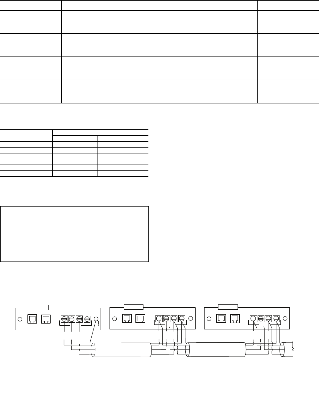
76
Table 11 — Pump Electrical Data
FLA — Full Load Amps
Table 12 — CCN Communication Bus Wiring
4. The RJ14 CCN connector on TB3 can also be used, but is
only intended for temporary connection (for example, a
laptop computer running service tool).
NON-CCN COMMUNICATION WIRING — The 30XA units
offer several non-CCN translators. Refer to the separate installa-
tion instructions for additional wiring steps.
FIELD CONTROL OPTION WIRING — Install field con-
trol wiring options. Some options, such as 4 to 20 mA demand
limit that requires the energy management module, may
require that accessories be installed first (if not factory
installed) for terminal connections.
DUAL CHILLER LEAVING WATER SENSOR — If the dual
chiller algorithm is used and the machines are installed in par-
allel, an additional chilled water sensor must be installed for
each chiller. Install the wells in the common leaving water
header. See Fig 39. DO NOT relocate the chiller’s leaving
water thermistors. They must remain in place for the unit to
operate properly.
The thermistor well is a 1/4 in. NPT fitting for securing the
well in the piping. The piping must be drilled and tapped for
the well. Select a location that will allow for removal of the
thermistor without any restrictions.
Once the well is inserted, install the thermistors. Insert the
thermistor into the well until the o-ring reaches the well body.
Use the nut on the thermistor to secure the thermistor in place.
Once the thermistor is in place, it is recommended that a
thermistor wire loop be made and secured with a wire tie to the
chilled water pipe. See Fig. 39.
For dual chiller control a CCN bus must be connected
between the two modules. See the Carrier Comfort Network
Communication Bus Wiring section for additional information.
PUMP
HP
UNIT VOLTAGE
V-Hz (3 Ph)
HYDRONIC SYSTEM (SINGLE OR DUAL)
FLA (Each)
30XA
UNIT SIZE
5
230-60 11.6
090-160
200-60 12.6
460-60 5.8
575-60 4.6
380-60 7.0
7.5
230-60 17.4
090-160
200-60 18.5
460-60 8.7
575-60 7.0
380-60 10.4
10
230-60 23.0
090-160
200-60 25.0
460-60 11.5
575-60 9.2
380-60 14.0
15
230-60 34.0
090-160
200-60 36.7
460-60 17.0
575-60 14.0
380-60 21.0
MANUFACTURER PART NUMBER
Regular Wiring Plenum Wiring
Alpha 1895 —
American A21451 A48301
Belden 8205 884421
Columbia D6451 —
Manhatten M13402 M64430
Quabik 6130 —
IMPORTANT: A shorted CCN bus cable will prevent
some routines from running and may prevent the unit
from starting. If abnormal conditions occur, disconnect
the machine from the CCN. If conditions return to
normal, check the CCN connector and cable. Run new
cable if necessary. A short in one section of the bus
can cause problems with all system elements on the
bus.
(+) (COM) (-) SHIELD
CCN
RED
WHT
BLK
CCNLEN
(+) (COM) (-) SHIELD
CCN
RED
WHT
BLK
CCNLEN
TO NEXT
DEVICE
(+) (COM) (-) SHIELD
CCN
RED
WHT
BLK
CCN
LEN
SHIELD
LEGEND
Fig. 38 — TB3 — CCN Wiring
CCN — Carrier Comfort Network®
LEN — Local Equipment Network
a30-4001
77
Step 6 — Install Accessories — A number of acces-
sories are available to provide the following optional features
(for details, refer to the Controls and Troubleshooting guide
shipped with the unit).
ENERGY MANAGEMENT MODULE — The energy man-
agement module is used for any of the following types of
temperature reset, demand limit and ice features:
• 4 to 20 mA inputs for cooling set point reset and capacity
limit (requires field-supplied 4 to 20 mA generator)
• 0 to 10 v output for percentage total capacity running
• 24 v discrete outputs for shutdown and running relays
• 10k space temperature input
Discrete inputs for occupancy override, demand limit
switch 2 (step 1 demand limit is wired to the base board,
requires field-supplied dry contacts), remote lockout switch
and ice done switch (requires field-supplied dry contacts).
REMOTE ENHANCED DISPLAY (OR TOUCH PILOT™
DISPLAY) — For applications where remote monitoring of
the equipment is required; the remote enhanced display (or
Touch Pilot display) provides an indoor display, capable of
monitoring any equipment on the Carrier Comfort Network®
(CCN) bus. A CCN bus is required.
LOW AMBIENT TEMPERATURE OPERATION — If out-
door ambient operating temperatures below 32 F (0° C) are
expected, refer to separate installation instructions for low-
ambient operation using the low ambient temperature head
pressure control accessory.
MINIMUM LOAD ACCESSORY — Contact your local
Carrier representative for more details if a minimum load ac-
cessory is required for a specific application. For installation
details, refer to separate installation instructions supplied with
the accessory package.
UNIT SECURITY/PROTECTION ACCESSORIES — For
applications with unique security and/or protection require-
ments, several options are available for unit protection.
Security grilles and hail guards are available. Contact a local
Carrier representative for more details. For installation details,
refer to separate installation instructions supplied with the
accessory package.
COMMUNICATION ACCESSORIES — A number of com-
munication options are available to meet any requirement.
Contact your local Carrier representative for more details. For
installation details, refer to separate installation instructions
supplied with the accessory package.
SERVICE OPTIONS — Two accessories are available to aid
in servicing 30XA units: a ground fault convenience outlet
(GFI-CO) and a remote service port.
The GFI-CO is a convenience outlet with a 4-amp GFI
receptacle.
The remote service port is housed in a weather-proof enclo-
sure with a communication port to plug in the Navigator™
device.
Contact your local Carrier representative for more details.
For installation details, refer to separate installation instructions
supplied with each accessory package.
CONTROL TRANSFORMER — The control transformer
accessory eliminates the need for a separate power supply.
Step 7 — Leak Test Unit — The 30XA units are
shipped with a complete operating charge of R-134a (see
Tables 1A and 1B) and should be under sufficient pressure to
conduct a leak test.
Perform a leak test to ensure that leaks have not developed
during unit shipment. Dehydration of the system is not required
unless the entire refrigerant charge has been lost. There are
several O-ring face seal fittings utilized in the oil line piping. If
a leak is detected at any of these fittings, open the system and
inspect the O-ring surface for foreign matter or damage. Do not
reuse O-rings. Repair any leak found following good refrigera-
tion practice.
Step 8 — Refrigerant Charging
DEHYDRATION — Refer to Carrier Standard Service Tech-
niques Manual, Chapter 1, Refrigerants, Sections 6 and 7 for
details. Do not use compressor to evacuate system.
5/8 in. HEX
6" MINIMUM
CLEARANCE FOR
THERMISTOR
REMOVAL
1.188 in.
2.315 in.
1/4-18 NPT
Fig. 39 — Dual Leaving Water Thermistor Well (Part No. 00PPG000008000A) and
Dual Leaving Water Thermistor (Part No. 00PPG000008105A)
a30-3999
WIRE TIE
LOOP
THERMISTOR WIRE
AND SECURE
TO CHILLED WATER PIPE
INSERT THERMISTOR UNTIL
O-RING MEETS THE
THERMISTOR WELL BODY.
a30-4000
IMPORTANT: These units are designed for use with
R-134a only. DO NOT USE ANY OTHER refriger-
ant in these units.
CAUTION
DO NOT OVERTIGHTEN THESE FITTINGS. Over-
tightening will result in O-ring damage.
78
REFRIGERANT CHARGE
The liquid charging method is recommended for complete
charging or when additional charge is required.
The 30XA units are shipped from the factory with a full
charge of R-134a. The unit should not need to be charged at
installation unless a leak was detected in Step 6 — Leak Test
Unit section. If dehydration and recharging is necessary, use
industry standard practices or refer to Carrier Standard Service
Techniques Manual as required.
IMPORTANT: These units are designed for use with
R-134a only. DO NOT USE ANY OTHER refrigerant in
these units.
CAUTION
When charging, circulate water through the cooler at all
times to prevent freezing. Freezing damage is considered
abuse and may void the Carrier warranty.
CAUTION
DO NOT OVERCHARGE system. Overcharging results
in higher discharge pressure with higher cooling fluid con-
sumption, possible compressor damage, and higher power
consumption.

Manufacturer reserves the right to discontinue, or change at any time, specifications or designs without notice and without incurring obligations.
Catalog No. 04-53300026-01 Printed in U.S.A. Form 30XA-10SI Pg 80 12-09A 11-09 Replaces: 30XA-5SI
Copyright 2009 Carrier Corporation
