Carrier Aquasnap Mpw015 045 Users Manual 30mp 1t
MPW015-045 to the manual e4caf960-1c0b-41e1-ab66-8d37e842de62
2015-01-24
: Carrier Carrier-Aquasnap-Mpw015-045-Users-Manual-311029 carrier-aquasnap-mpw015-045-users-manual-311029 carrier pdf
Open the PDF directly: View PDF ![]() .
.
Page Count: 80
Manufacturer reserves the right to discontinue, or change at any time, specifications or designs without notice and without incurring obligations.
Catalog No. 04-53300053-01 Printed in U.S.A. Form 30MP-1T Pg 1 1-10 Replaces: New
Controls, Start-Up, Operation,
Service, and Troubleshooting
SAFETY CONSIDERATIONS
Installing, starting up, and servicing this equipment can be
hazardous due to system pressures, electrical components, and
equipment location (elevated structures, mechanical rooms,
etc.). Only trained, qualified installers and service mechanics
should install, start up, and service this equipment.
When working on this equipment, observe precautions in
the literature, and on tags, stickers, and labels attached to the
equipment, and any other safety precautions that apply. Follow
all safety codes. Wear safety glasses and work gloves. Use
care in handling, rigging, and setting this equipment, and in
handling all electrical components.
WARNING
Electrical shock can cause personal injury and death. Shut
off all power to this equipment during installation. There
may be more than one disconnect switch. Tag all discon-
nect locations to alert others not to restore power until work
is completed.
WARNING
DO NOT VENT refrigerant relief valves within a building.
Outlet from relief valves must be vented outdoors in
accordance with the latest edition of ANSI/ASHRAE
(American National Standards Institute/American Society
of Heating, Refrigerating and Air Conditioning Engineers)
15 (Safety Code for Mechanical Refrigeration). The
accumulation of refrigerant in an enclosed space can
displace oxygen and cause asphyxiation. Provide adequate
ventilation in enclosed or low overhead areas. Inhalation of
high concentrations of vapor is harmful and may cause
heart irregularities, unconsciousness or death. Misuse can
be fatal. Vapor is heavier than air and reduces the amount
of oxygen available for breathing. Product causes eye and
skin irritation. Decomposition products are hazardous.
WARNING
DO NOT attempt to unbraze factory joints when servicing
this equipment. Compressor oil is flammable and there is
no way to detect how much oil may be in any of the
refrigerant lines. Cut lines with a tubing cutter as required
when performing service. Use a pan to catch any oil that
may come out of the lines and as a gage for how much oil
to add to system. DO NOT re-use compressor oil. Damage
to equipment or personal injury may result.
CAUTION
This unit uses a microprocessor-based electronic control
system. Do not use jumpers or other tools to short out
components, or to bypass or otherwise depart from recom-
mended procedures. Any short-to-ground of the control
board or accompanying wiring may destroy the electronic
modules or electrical components.
CAUTION
To prevent potential damage to heat exchanger, always run
fluid through heat exchanger when adding or removing
refrigerant charge. Use appropriate brine solutions in cooler
fluid loop to prevent the freezing of brazed plate heat
exchanger when the equipment is exposed to temperatures
below 32 F (0° C). Proof of flow switch is factory installed
on all models. Do NOT remove power from this chiller dur-
ing winter shutdown periods without taking precaution to
remove all water from heat exchanger and optional
hydronic system. Failure to properly protect the system
from freezing may constitute abuse and may void warranty.
CAUTION
Compressors require specific rotation. Monitor control
alarms during first compressor start up for reverse rotation
protection. Damage to unit may result.
CAUTION
Refrigerant charge must be removed slowly to prevent loss
of compressor oil that could result in compressor failure.
CAUTION
Puron® refrigerant (R-410A) systems operate at higher
pressures than standard R-22 systems. Do not use R-22 ser-
vice equipment or components on Puron refrigerant equip-
ment. If service equipment is not rated for Puron
refrigerant, equipment damage or personal injury may
result.
AQUASNAP®
30MPA,MPW015-045
Liquid Chillers with Scroll Compressors
and ComfortLink™ Controls
2
CONTENTS
Page
SAFETY CONSIDERATIONS. . . . . . . . . . . . . . . . . . . . . . . . . 1
GENERAL. . . . . . . . . . . . . . . . . . . . . . . . . . . . . . . . . . . . . . . . 2-13
Conventions Used in this Manual . . . . . . . . . . . . . . . . . . . 2
Basic Controls Usage . . . . . . . . . . . . . . . . . . . . . . . . . . . . . . . 3
CONTROLS . . . . . . . . . . . . . . . . . . . . . . . . . . . . . . . . . . . . . 14-33
General . . . . . . . . . . . . . . . . . . . . . . . . . . . . . . . . . . . . . . . . . . . . 14
Main Base Board (MBB). . . . . . . . . . . . . . . . . . . . . . . . . . . . 14
Energy Management Module (EMM). . . . . . . . . . . . . . . . 14
Current Sensor Board (CSB) . . . . . . . . . . . . . . . . . . . . . . . 14
Enable/Off/Remote Contact Switch. . . . . . . . . . . . . . . . . 14
Emergency On/Off Switch. . . . . . . . . . . . . . . . . . . . . . . . . . 14
Board Addresses . . . . . . . . . . . . . . . . . . . . . . . . . . . . . . . . . . 14
Control Module Communication . . . . . . . . . . . . . . . . . . . 14
Carrier Comfort Network® Interface . . . . . . . . . . . . . . . . 14
Sensors. . . . . . . . . . . . . . . . . . . . . . . . . . . . . . . . . . . . . . . . . . . . 19
• COOLER LEAVING FLUID SENSOR
• COOLER ENTERING FLUID SENSOR
• CONDENSER LEAVING FLUID SENSOR
• CONDENSER ENTERING FLUID SENSOR
• COMPRESSOR RETURN GAS
TEMPERATURE SENSOR
• OUTDOOR-AIR TEMPERATURE SENSOR
• DUAL LEAVING WATER TEMPERATURE SENSOR
• REMOTE SPACE TEMPERATURE SENSOR
Energy Management Module . . . . . . . . . . . . . . . . . . . . . . . 21
Loss-of-Cooler Flow Protection . . . . . . . . . . . . . . . . . . . . 21
Condenser Flow Protection . . . . . . . . . . . . . . . . . . . . . . . . 21
Thermostatic Expansion Valves (TXV) . . . . . . . . . . . . . 21
Capacity Control . . . . . . . . . . . . . . . . . . . . . . . . . . . . . . . . . . . 21
• MINUTES LEFT FOR START
• MINUTES OFF TIME
• LEAD/LAG DETERMINATION
• CAPACITY CONTROL OVERRIDES
Operation of Machine Based on Control Method
and Cooling Set Point Selection Settings . . . . . . . . 24
Cooling Set Point Select . . . . . . . . . . . . . . . . . . . . . . . . . . . 24
Cooler Pump Control . . . . . . . . . . . . . . . . . . . . . . . . . . . . . . 24
Ice Mode . . . . . . . . . . . . . . . . . . . . . . . . . . . . . . . . . . . . . . . . . . . 24
Service Test. . . . . . . . . . . . . . . . . . . . . . . . . . . . . . . . . . . . . . . . 24
Cooler Pump Sequence of Operation . . . . . . . . . . . . . . 25
Condenser Pump/Condenser Fan Output
Control . . . . . . . . . . . . . . . . . . . . . . . . . . . . . . . . . . . . . . . . 25
Configuring and Operating Dual Chiller Control. . . . 25
Temperature Reset. . . . . . . . . . . . . . . . . . . . . . . . . . . . . . . . . 27
Demand Limit . . . . . . . . . . . . . . . . . . . . . . . . . . . . . . . . . . . . . . 31
• DEMAND LIMIT (2-Stage Switch Controlled)
• EXTERNALLY POWERED DEMAND LIMIT
(4 to 20 mA Controlled)
• DEMAND LIMIT (CCN Loadshed Controlled)
Cooling Set Point (4 to 20 mA) . . . . . . . . . . . . . . . . . . . . . 32
PRE-START-UP. . . . . . . . . . . . . . . . . . . . . . . . . . . . . . . . . . .33,34
System Check . . . . . . . . . . . . . . . . . . . . . . . . . . . . . . . . . . . . . 33
START-UP AND OPERATION . . . . . . . . . . . . . . . . . . . . 34-36
Actual Start-Up . . . . . . . . . . . . . . . . . . . . . . . . . . . . . . . . . . . . 34
Check Refrigerant Charge. . . . . . . . . . . . . . . . . . . . . . . . . . 34
Operating Limitations. . . . . . . . . . . . . . . . . . . . . . . . . . . . . . 35
• TEMPERATURES
• VOLTAGE — ALL UNITS
OPERATION SEQUENCE . . . . . . . . . . . . . . . . . . . . . . . . 36
SERVICE . . . . . . . . . . . . . . . . . . . . . . . . . . . . . . . . . . . . . 36-44
Electronic Components . . . . . . . . . . . . . . . . . . . . . . . . . . . . 36
• CONTROL COMPONENTS
Compressor Replacement . . . . . . . . . . . . . . . . . . . . . . . . . 36
30MPW Condenser and 30MP Cooler . . . . . . . . . . . . . . 36
• BRAZED-PLATE COOLER AND CONDENSER
HEAT EXCHANGER REPLACEMENT
• BRAZED-PLATE COOLER AND CONDENSER
HEAT EXCHANGER CLEANING
Oil Charge . . . . . . . . . . . . . . . . . . . . . . . . . . . . . . . . . . . . . . . . . 37
Check Refrigerant Feed Components . . . . . . . . . . . . . . 37
• FILTER DRIER
• MOISTURE-LIQUID INDICATOR
• THERMOSTATIC EXPANSION VALVE (TXV)
• MINIMUM LOAD VALVE
• PRESSURE RELIEF DEVICES
Check Unit Safeties. . . . . . . . . . . . . . . . . . . . . . . . . . . . . . . . 38
Thermistors. . . . . . . . . . . . . . . . . . . . . . . . . . . . . . . . . . . . . . . . 38
Pressure Transducers . . . . . . . . . . . . . . . . . . . . . . . . . . . . . 38
Chilled Water Flow Switch . . . . . . . . . . . . . . . . . . . . . . . . . 39
Strainer . . . . . . . . . . . . . . . . . . . . . . . . . . . . . . . . . . . . . . . . . . . . 43
Replacing Defective Modules. . . . . . . . . . . . . . . . . . . . 43
MAINTENANCE . . . . . . . . . . . . . . . . . . . . . . . . . . . . . . . . . . 44,45
Recommended Maintenance Schedule . . . . . . . . . . . . 44
TROUBLESHOOTING . . . . . . . . . . . . . . . . . . . . . . . . . . . .44-52
Complete Unit Stoppage and Restart . . . . . . . . . . . . . . 44
• GENERAL POWER FAILURE
• UNIT ENABLE-OFF-REMOTE CONTACT SWITCH IS
OFF
• CHILLED FLUID PROOF-OF-FLOW SWITCH OPEN
• OPEN 24-V CONTROL CIRCUIT BREAKERS
• COOLING LOAD SATISFIED
• THERMISTOR FAILURE
• LOW SATURATED SUCTION
• COMPRESSOR SAFETIES
Alarms and Alerts . . . . . . . . . . . . . . . . . . . . . . . . . . . . . . . . . 45
APPENDIX A — LOCAL DISPLAY TABLES . . . . . . .53-64
APPENDIX B — CCN TABLES. . . . . . . . . . . . . . . . . . . .65-72
START-UP CHECKLIST FOR 30MP LIQUID
CHILLER. . . . . . . . . . . . . . . . . . . . . . . . . . . . . . CL-1 to CL-8
GENERAL
This publication contains Start-Up, Service, Controls, Oper-
ation, and Troubleshooting information for the 30MPW water-
cooled chillers and the 30MPA air-cooled chillers. See Table 1.
These liquid chillers are equipped with ComfortLink controls
and conventional thermostatic expansion valves (TXVs). The
30MPA units and the 30MPW units with optional medium
temperature brine are also equipped with liquid line solenoid
valves (LLSVs).
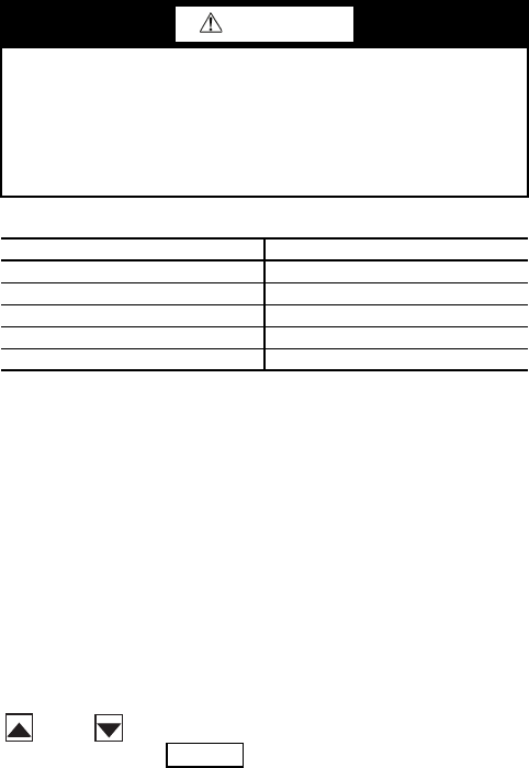
Table 1 — Unit Sizes
Conventions Used in This Manual — The follow-
ing conventions for discussing configuration points for the
local display (scrolling marquee or Navigator™ accessory)
will be used in this manual.
Point names will be written with the mode name first, then
any sub-modes, then the point name, each separated by an
arrow symbol (. Names will also be shown in bold
and italics. As an example, the Minimum Load Valve Select
Point, which is located in the Configuration mode, Option 1
sub-mode, would be written as ConfigurationOPT1
MLV.S.
This path name will show the user how to navigate through
the local display to reach the desired configuration. The user
would scroll through the modes and sub-modes using the
and keys. The arrow symbol in the path name
represents pressing to move into the next level of the
menu structure.
CAUTION
This unit uses a microprocessor-based electronic control
system. Do not use jumpers or other tools to short out or
bypass components or otherwise depart from recom-
mended procedures. Any short-to-ground of the control
board or accompanying wiring may destroy the board or
electrical component.
UNIT MODEL NOMINAL TONS
30MPA,MPW015 15
30MPA,MPW020 20
30MPA,MPW030 30
30MPA,MPW040 40
30MPA,MPW045 45
ENTER
3
When a value is included as part of the path name, it will be
shown at the end of the path name after an equals sign. If the
value represents a configuration setting, an explanation will
be shown in parenthesis after the value. As an example,
ConfigurationOPT1MLV.S = 1 (Minimum Load Valve
Select).
Pressing the and keys simultaneously
will scroll an expanded text description of the point name or
value across the display. The expanded description is shown in
the local display tables but will not be shown with the path
names in text.
The CCN (Carrier Comfort Network®) point names are also
referenced in the local display tables for users configuring the
unit with CCN software instead of the local display. The CCN
tables are located in Appendix B of the manual.
Basic Control Usage
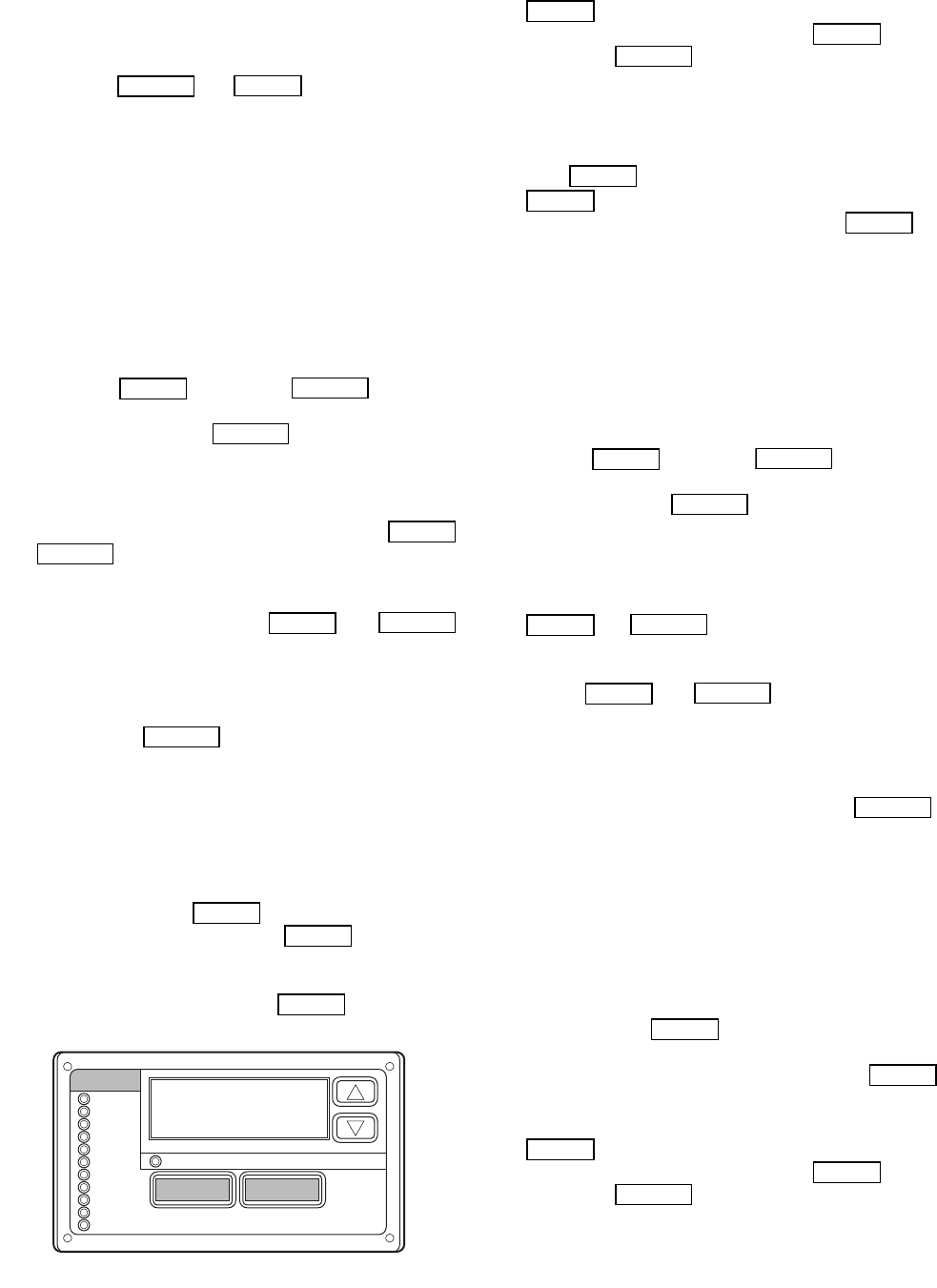
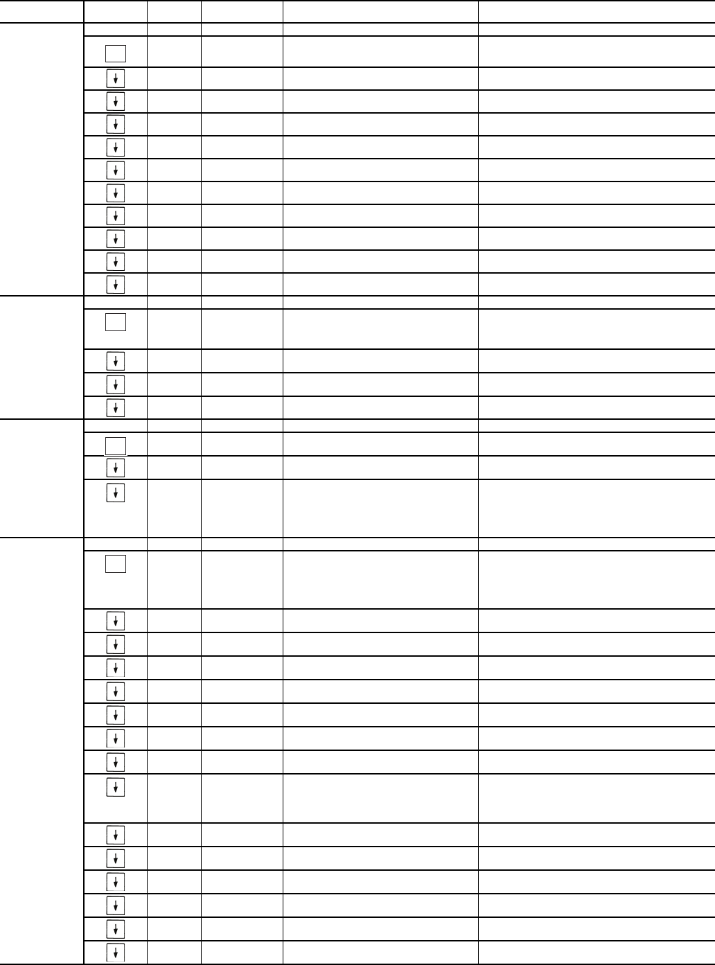
SCROLLING MARQUEE DISPLAY — The scrolling mar-
quee display is the standard interface display to the ComfortLink
Control System for 30MP units. The display has up and down
arrow keys, an key, and an key. These
keys are used to navigate through the different levels of the
display structure. Press the key until the highest
operating level is displayed to move through the top 11 mode
levels indicated by LEDs (light emitting diodes) on the left side
of the display. See Fig. 1 and Tables 2-14.
Once within a mode or sub-mode, pressing the
and keys simultaneously will put the scrolling
marquee display into expanded text mode where the full mean-
ing of all sub-modes, items and their values can be displayed
for the current selection. Press the and
keys to return the scrolling marquee display to its default menu
of rotating display items (those items in Run Status
VIEW).
In addition, the password will be disabled, requiring that it be
entered again before changes can be made to password protect-
ed items. Press the key to exit out of the expanded
text mode.
NOTE: When the Language Selection (Configuration
DISP
LANG), variable is changed, all appropriate display
expansions will immediately change to the new language. No
power-off or control reset is required when reconfiguring
languages.
When a specific item is located, the item name alternates
with the value. Press the key at a changeable item
and the value will be displayed. Press again and the
value will begin to flash indicating that the value can be
changed. Use the up and down arrow keys to change the value,
and confirm the value by pressing the key.
Changing item values or testing outputs is accomplished in
the same manner. Locate and display the desired item. Press
so that the item value flashes. Use the arrow keys to
change the value or state and press the key to accept
it. Press the key to return to the next higher level of
structure. Repeat the process as required for other items.
Items in the Configuration and Service Test modes are pass-
word protected. The words ‘PASS’ and ‘WORD’ will alternate
on the display when required. The default password is 0111.
Press and the 1111 password will be displayed. Press
again and the first digit will begin to flash. Use the
arrow keys to change the number and press to accept
the digit. Continue with the remaining digits of the password.
The password can only be changed through CCN operator in-
terface software such as ComfortWORKS®, ComfortVIEW™
and Service Tool.
See Tables 2-14 and Appendix A for further details.
ACCESSORY NAVIGATOR™ DISPLAY MODULE —
The Navigator module provides a mobile user interface to the
ComfortLink™ control system, which is only available as a
field-installed accessory. The display has up and down arrow
keys, an key, and an key. These keys are
used to navigate through the different levels of the display
structure. Press the key until ‘Select a Menu Item’
is displayed to move through the top 11 mode levels indicated
by LEDs on the left side of the display. See Fig. 2.
Once within a Mode or sub-mode, a “>” indicates the cur-
rently selected item on the display screen. Pressing the
and keys simultaneously will put the Nav-
igator module into expanded text mode where the full meaning
of all sub-modes, items and their values can be displayed. Press-
ing the and keys when the display says
‘Select Menu Item’ (Mode LED level) will return the Navigator
module to its default menu of rotating display items (those items
in Run Status
VIEW). In addition, the password will be dis-
abled, requiring that it be entered again before changes can be
made to password protected items. Press the key to
exit out of the expanded text mode.
NOTE: When the Language Selection (Configuration
DISP
LANG), variable is changed, all appropriate display
expansions will immediately change to the new language. No
power-off or control reset is required when reconfiguring
languages.
When a specific item is located, the item name appears on the
left of the display, the value will appear near the middle of the
display and the units (if any) will appear on the far right of the
display. Press the key at a changeable item and the val-
ue will begin to flash. Use the up and down arrow keys to change
the value, and confirm the value by pressing the key.
Changing item values or testing outputs is accomplished in
the same manner. Locate and display the desired item. Press
so that the item value flashes. Use the arrow keys to
change the value or state and press the key to accept
it. Press the key to return to the next higher level of
structure. Repeat the process as required for other items.
Items in the Configuration and Service Test modes are pass-
word protected. The words Enter Password will be displayed
when required, with 1111 also being displayed. The default
password is 1111. Use the arrow keys to change the number
ESCAPE
ENTER
ENTER
ESCAPE
ESCAPE
ENTER
ESCAPE
ENTER
ESCAPE
ESCAPE
ENTER
ENTER
ENTER
Run Status
Service Test
Temperature
Pressures
Setpoints
Inputs
Outputs
Configuration
Time Clock
Operating Modes
Alarms
Alarm Status
ENTER
MODE
ESCAPE
Fig. 1 — Scrolling Marquee Display
ENTER
ENTER
ESCAPE
ENTER
ENTER
ENTER
ENTER
ESCAPE
ESCAPE
ENTER
ESCAPE
ENTER
ESCAPE
ESCAPE
ENTER
ENTER
ENTER
ENTER
ESCAPE
4
and press to enter the digit. Continue with the re-
maining digits of the password. The password can only be
changed through CCN operator interface software such as
ComfortWORKS, ComfortVIEW and Service Tool.
Adjusting the Contrast — The contrast of the display can be
adjusted to suit ambient conditions. To adjust the contrast of
the Navigator module, press the key until the dis-
play reads, “Select a menu item.” Using the arrow keys move
to the Configuration mode. Press to obtain access to
this mode. The display will read:
> TEST OFF
METR OFF
LANG ENGLISH
Pressing will cause the “OFF” to flash. Use the up
or down arrow to change “OFF” to “ON”. Pressing
will illuminate all LEDs and display all pixels in the view
screen. Pressing and simultaneously
allows the user to adjust the display contrast. Use the up or
down arrows to adjust the contrast. The screen’s contrast will
change with the adjustment. Press to accept the
change. The Navigator module will keep this setting as long as
it is plugged in to the LEN bus.
Adjusting the Backlight Brightness — The backlight of the
display can be adjusted to suit ambient conditions. The factory
default is set to the highest level. To adjust the backlight of the
Navigator module, press the key until the display
reads, “Select a menu item.” Using the arrow keys move to the
Configuration mode. Press to obtain access to this
mode. The display will read:
> TEST OFF
METR OFF
LANG ENGLISH
Pressing will cause the “OFF” to flash. Use the up
or down arrow keys to change “OFF” to “ON”. Pressing
will illuminate all LEDs and display all pixels in the
view screen. Pressing the up and down arrow keys simultane-
ously allows the user to adjust the display brightness. Use the
up or down arrow keys to adjust screen brightness. Press
to accept the change. The Navigator module will
keep this setting as long as it is plugged in to the LEN bus.
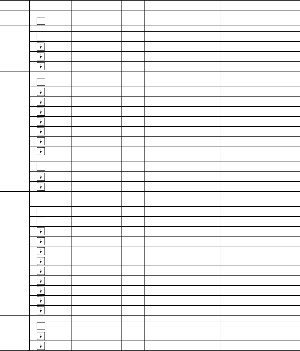
Table 2 — Scrolling Marquee Display Menu Structure*
LEGEND
Ckt — Circuit
*Throughout this text, the location of items in the menu structure will be
described in the following format:
Item Expansion (Mode Name
Sub-mode Name
ITEM)
For example, using the language selection item:
Language Selection (Configuration
DISP
LANG)
ENTER
ESCAPE
ENTER
ENTER
ENTER
ENTER
ESCAPE
ENTER
ESCAPE
ENTER
ENTER
ENTER
ENTER
Run Status
Service Tes t
Tem peratures
Pressures
Setpoints
Inputs
Outputs
Configuration
Time Clock
Operating Modes
Alarms
ENTER
ESC
MODE
Alarm Status
ComfortLink
Fig. 2 — Accessory Navigator™ Display Module
MODE RUN
STATUS
SERVICE
TEST TEMPERATURES PRESSURES SET
POINTS INPUTS OUTPUTS CONFIGURATION TIME
CLOCK
OPERATING
MODES ALARMS
SUB-MODE
Auto
View of
Run Status
(VIEW)
Service
Te s t M o d e
(TEST)
Unit Temperatures
(UNIT)
Pressures
Circuit A
(PRC.A)
Cooling
Setpoints
(COOL)
General
Inputs
(GEN.I)
General
Outputs
(GEN.O)
Display
Configuration
(DISP)
Time of
Day
(TIME)
Modes
(MODE)
Current
(CRNT)
Unit Run
Hour and
Start
(RUN)
Outputs
and Pumps
(OUTS)
Temperatures
Circuit A
(CIR.A)
Head
Pressure
Setpoint
(HEAD)
Circuit
Inputs
(CRCT)
Outputs
Circuit A
(CIR.A)
Unit
Configuration
(UNIT)
Month,
Date, Day,
and Year
(DATE)
Reset
Alarms
(RCRN)
Circuit and
Compressor
Run Hours
(HOUR)
Ciruit A Comp
Te s t
(CMPA)
Brine
Freeze
Setpoint
(FRZ)
4-20mA
Inputs
(4-20)
Unit Options 1
Hardware
(OPT1)
Daylight
Savings
Time
(DST)
Alarm
History
(HIST)
Local
Holiday
Schedules
(HOL.L)
Compressor
Starts
(STRT)
Unit Options 2
Controls
(OPT2)
Preventive
Maintenance
(PM)
CCN Network
Configuration
(CCN)
Schedule
Number
(SCH.N)
Software
Version
(VERS)
Reset Cool Temp
(RSET)
Local
Occu-
pancy
Schedule
(SCH.L)
Set Point and
Ramp Load
(SLCT)
Schedule
Override
(OVR)
Service
Configuration
(SERV)
Broadcast
Configuration
(BCST)
5
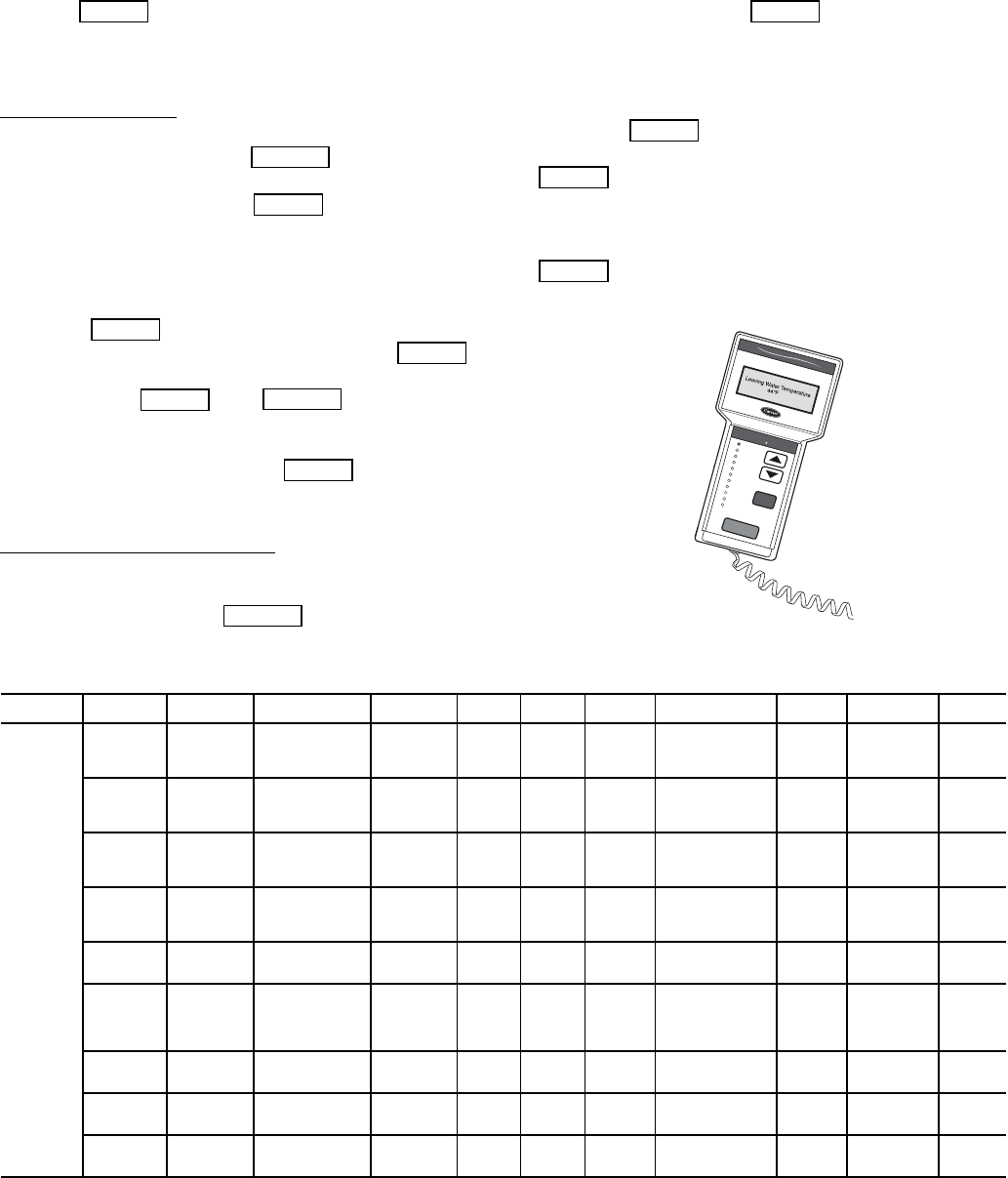
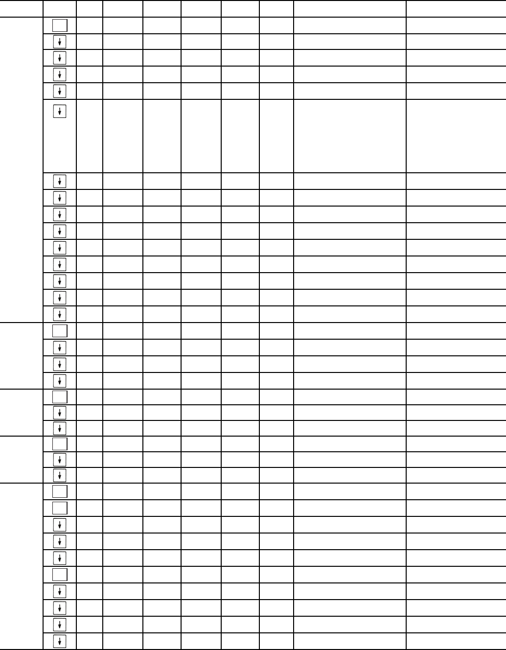
Table 3 — Run Status Mode and Sub-Mode Directory
SUB-MODE KEYPAD
ENTRY ITEM DISPLAY SUB-ITEM DISPLAY SUB-ITEM DISPLAY ITEM
EXPANSION COMMENT
VIEW EWT XXX.X FENTERING FLUID TEMP
LWT XXX.X FLEAVING FLUID TEMP
SETP XXX.X FACTIVE SETPOINT
CTPT XXX.X FCONTROL POINT
LOD.F XXX LOAD/UNLOAD FACTOR
STAT X CONTROL MODE 0 = Service Test
1 = Off Local
2 = Off CCN
3 = Off Time
4 = Off Emrgcy
5 = On Local
6 = On CCN
7 = On Time
8 = Ht Enabled
9 = Pump Delay
OCC YES/NO OCCUPIED
MODE YES/NO OVERRIDE MODES IN EFFECT
CAP XXX % PERCENT TOTAL CAPACITY
STGE X REQUESTED STAGE
ALRM XXX CURRENT ALARMS & ALERTS
TIME XX.XX TIME OF DAY 00.00-23.59
MNTH XX MONTH OF YEAR 1 = January, 2 = February, etc.
DATE XX DAY OF MONTH 01-31
YEAR XX YEAR OF CENTURY
RUN HRS.U XXXX HRS MACHINE OPERATING HOURS
STR.U XXXX MACHINE STARTS
HR.P1 XXXX.X PUMP 1 RUN HOURS
HR.P2 XXXX.X PUMP 2 RUN HOURS
HOUR HR.A1 XXXX HRS COMPRESSOR A1 RUN HOURS
HR.A2 XXXX HRS COMPRESSOR A2 RUN HOURS
HR.A3 XXXX HRS COMPRESSOR A3 RUN HOURS
STRT ST.A1 XXXX COMPRESSOR A1 STARTS
ST.A2 XXXX COMPRESSOR A2 STARTS
ST.A3 XXXX COMPRESSOR A3 STARTS
PM STRN STRAINER MAINTENANCE
SI.ST XXXX HRS STRAINER SRVC INTERVAL
S.T.DN XXXX HRS STRAINER SRVC COUNTDOWN
S.T.MN YES/NO STRAINER MAINT. DONE User Entry
ST.DT STRAINER MAINT. DATES
S.T.M0 MM/DD/YY HH:MM
S.T.M1 MM/DD/YY HH:MM
S.T.M2 MM/DD/YY HH:MM
S.T.M3 MM/DD/YY HH:MM
S.T.M4 MM/DD/YY HH:MM
ENTER
ENTER
ENTER
ENTER
ENTER
ENTER
ENTER
6
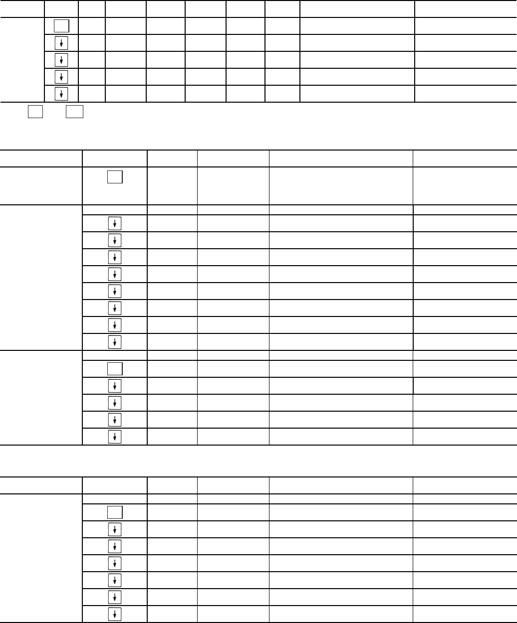
Table 3 — Run Status Mode and Sub-Mode Directory (cont)
*Press and simultaneously to obtain version number.
Table 4 — Service Test Mode and Sub-Mode Directory
Table 5 — Temperature Mode and Sub-Mode Directory
SUB-MODE KEYPAD
ENTRY ITEM DISPLAY SUB-ITEM DISPLAY SUB-ITEM DISPLAY ITEM
EXPANSION COMMENT
VERS AUX CESR131333-xx-xx xx-xx is Version number*
MBB CESR131279-xx-xx xx-xx is Version number*
EMM CESR131174-xx-xx xx-xx is Version number*
MARQ CESR131171-xx-xx xx-xx is Version number*
NAVI CESR130227-xx-xx xx-xx is Version number*
ENTER
ENTER
ESCAPE
SUB-MODE KEYPAD
ENTRY ITEM DISPLAY ITEM
EXPANSION COMMENT
TEST ON/OFF SERVICE TEST MODE To Enable Service Test Mode,
move Enable/Off/Remote
Contact switch to OFF. Change
TEST to ON. Move switch to
ENABLE.
OUTS OUTPUTS AND PUMPS
CLR.P ON/OFF COOLER PUMP RELAY
CND.P ON/OFF CONDENSER PUMP
UL.TM 0 to 15 COMP A1 UNLOAD TIME
CC.H ON/OFF CRANKCASE HEATER
CW.VO ON/OFF CONDENSER VALVE OPEN
CW.VC ON/OFF CONDENSER VALVE CLOSE
LL.SV ON/OFF LIQUID LINE SOLENOID
RMT.A ON/OFF REMOTE ALARM RELAY
CMPA CIRCUIT A COMPRESSOR TEST
CC.A1 ON/OFF COMPRESSOR A1 RELAY
UL.TM 0 to 15 COMP A1 UNLOAD TIME
CC.A2 ON/OFF COMPRESSOR A2 RELAY
CC.A3 ON/OFF COMPRESSOR A3 RELAY
MLV ON/OFF MINIMUM LOAD VALVE RELAY
SUB-MODE KEYPAD
ENTRY ITEM DISPLAY ITEM
EXPANSION COMMENT
UNIT ENT AND LEAVE UNIT TEMPS
CEWT XXX.X FCOOLER ENTERING FLUID
CLWT XXX.X FCOOLER LEAVING FLUID
CDET XXX.X FCONDENSER ENTERING FLUID
CDLT XXX.X FCONDENSER LEAVING FLUID
OAT XXX.X FOUTSIDE AIR TEMPERATURE
SPT XXX.X FSPACE TEMPERATURE
DLWT XXX.X FLEAD/LAG LEAVING FLUID
ENTER
ENTER
ENTER
7
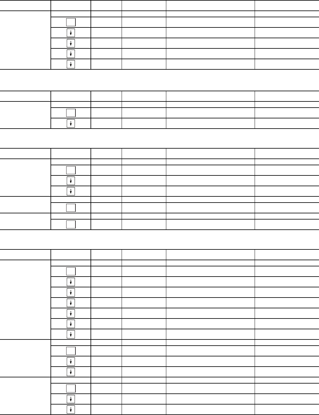
Table 5 — Temperature Mode and Sub-Mode Directory (cont)
Table 6 — Pressure Mode and Sub-Mode Directory
Table 7 — Set Points Mode and Sub-Mode Directory
Table 8 — Inputs Mode and Sub-Mode Directory
SUB-MODE KEYPAD
ENTRY ITEM DISPLAY ITEM
EXPANSION COMMENT
CIR.A TEMPERATURES CIRCUIT A
SCT.A XXX.X FSATURATED CONDENSING TMP
SST.A XXX.X FSATURATED SUCTION TEMP
RGT.A XXX.X FCOMPR RETURN GAS TEMP
D.GAS XXX.X FDISCHARGE GAS TEMP
SH.A XXX.X ^F SUCTION SUPERHEAT TEMP
SUB-MODE KEYPAD
ENTRY ITEM DISPLAY ITEM
EXPANSION COMMENT
PRC.A PRESSURES CIRCUIT A
DP.A XXX.X PSIG DISCHARGE PRESSURE
SP.A XXX.X PSIG SUCTION PRESSURE
SUB-MODE KEYPAD
ENTRY ITEM DISPLAY ITEM
EXPANSION COMMENT
COOL COOLING SETPOINTS
CSP.1 XXX.X FCOOLING SETPOINT 1 Default: 44 F
CSP.2 XXX.X FCOOLING SETPOINT 2 Default: 44 F
CSP.3 XXX.X FICE SETPOINT Default: 32 F
HEAD HEAD PRESSURE SETPOINTS
H.DP XXX.X FHEAD SETPOINT Default: 95 F
FRZ BRINE FREEZE SETPOINT
BR.FZ XXX.X FBRINE FREEZE POINT Default: 34 F
SUB-MODE KEYPAD
ENTRY ITEM DISPLAY ITEM
EXPANSION COMMENT
GEN.I GENERAL INPUTS
STST STRT/STOP START/STOP SWITCH
FLOW ON/OFF COOLER FLOW SWITCH
CD.FL OPEN/CLSE CONDENSER FLOW SWITCH
DLS1 ON/OFF DEMAND LIMIT SWITCH 1
DLS2 ON/OFF DEMAND LIMIT SWITCH 2
ICED ON/OFF ICE DONE
DUAL ON/OFF DUAL SETPOINT SWITCH
CRCT CIRCUITS INPUTS
FKA1 ON/OFF COMPRESSOR A1 FEEDBACK
FKA2 ON/OFF COMPRESSOR A2 FEEDBACK
FKA3 ON/OFF COMPRESSOR A3 FEEDBACK
4-20 4-20 MA INPUTS
DMND XX.X MA 4-20 MA DEMAND SIGNAL
RSET XX.X MA 4-20 MA RESET SIGNAL
CSP XX.X MA 4-20 MA COOLING SETPOINT
ENTER
ENTER
ENTER
ENTER
ENTER
ENTER
ENTER
ENTER
8
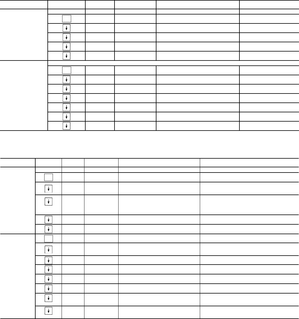
Table 9 — Outputs Mode and Sub-Mode Directory
Table 10 — Configuration Mode and Sub-Mode Directory
SUB-MODE KEYPAD
ENTRY ITEM DISPLAY ITEM
EXPANSION COMMENT
GEN.O GENERAL OUTPUTS
C.LWP ON/OFF COOLER PUMP RELAY
C.DWP ON/OFF CONDENSER PUMP
ALRM ON/OFF ALARM RELAY
CDWO ON/OFF CONDENSER VALVE OPEN
CDWC ON/OFF CONDENSER VALVE CLOSE
CIR.A OUTPUTS CIRCUIT A
CC.A1 ON/OFF COMPRESSOR A1 RELAY
D.SOL ON/OFF DIGITAL SCROLL SOLENOID
CC.A2 ON/OFF COMPRESSOR A2 RELAY
CC.A3 ON/OFF COMPRESSOR A3 RELAY
CCH ON/OFF CRANKCASE HEATER RELAY
LLSV ON/OFF LIQUID LINE SOLENOID
MLV.R ON/OFF MINIMUM LOAD VALVE RELAY
SUB-MODE KEYPAD
ENTRY ITEM DISPLAY ITEM
EXPANSION COMMENT
DISP DISPLAY CONFIGURATION
TEST ON/OFF TEST DISPLAY LEDS
METR ON/OFF METRIC DISPLAY Off = English
On = Metric
LANG X LANGUAGE SELECTION Default: 0
0 = English
1 = Espanol
2 = Francais
3 = Portuguese
PAS.E ENBL/DSBL PASSWORD ENABLE Default: Enable
PASS xxxx SERVICE PASSWORD Default: 1111
UNIT UNIT CONFIGURATION
TYPE x UNIT TYPE 2=WaterCooled
3=Split System
SIZE XX UNIT SIZE
SZA.1 XX COMPRESSOR A1 SIZE Unit Dependent
SZA.2 XX COMPRESSOR A2 SIZE Unit Dependent
SZA.3 XX COMPRESSOR A3 SIZE Unit Dependent
A1.TY No/Yes COMPRESSOR A1 DIGITAL? Default: Yes (A1 Digital Scroll)
MAX.T 0 to 15 MAXIMUM A1 UNLOAD TIME Default: 7
ENTER
ENTER
ENTER
ENTER
9
Table 10 — Configuration Mode and Sub-Mode Directory (cont)
SUB-MODE KEYPAD
ENTRY ITEM DISPLAY ITEM
EXPANSION COMMENT
OPT1 UNIT OPTIONS 1 HARDWARE
FLUD X COOLER FLUID
Default: Water
1 = Water
2 = Medium Temperature Brine
MLV.S YES/NO MINIMUM LOAD VALVE SELECT Default: No
R.G.EN ENBL/DSBL RETURN GAS SENSOR ENABLE
OAT.E ENBL/DSBL ENABLE OAT SENSOR
D.G.EN ENBL/DSBL DISCHARGE GAS TEMP ENABLE
CSB.E ENBL/DSBL CSB BOARDS ENABLE
CPC ON/OFF COOLER PUMP CONTROL Default: On
PM.DY XX MIN COOLER PUMP SHUTDOWN DLY 0 to 10 minutes, Default: 1 min.
DPME x ENABLE CONDENSER PUMP 0 to 2
DFLS ENBL/DSBL ENABLE COND FLOW SWITCH
CDWS ENBL/DSBL ENABLE COND WTR SENSORS
OPT2 UNIT OPTIONS 2 CONTROLS
CTRL X CONTROL METHOD Default: Switch
0 = Enable/Off/Remote Switch
2 = Occupancy
3 = CCN Control
LCWT XX.X FHIGH LCW ALERT LIMIT Default: 60
Range: 2 to 60 F
DELY XX MINUTES OFF TIME Default: 0 Minutes
Range: 0 to 15 Minutes
ICE.M ENBL/DSBL ICE MODE ENABLE Default: Disable
CCN CCN NETWORK CONFIGURATION
CCNA XXX CCN ADDRESS Default: 1
Range: 1 to 239
CCNB XXX CCN BUS NUMBER Default: 0
Range: 0 to 239
BAUD X CCN BAUD RATE Default: 9600
1 = 2400
2 = 4800
3 = 9600
4 = 19,200
5 = 38,400
RSET RESET COOL TEMP
CRST X COOLING RESET TYPE Default: No Reset
0 = No Reset
1 = 4 to 20 mA Input
2 = Outdoor Air Temperature
3 = Return Fluid
4 = Space Temperature
MA.DG XX.X F4-20 - DEGREES RESET Default: 0.0F
Range: –30 to 30F
RM.NO XXX.X FREMOTE - NO RESET TEMP Default: 125F (51.7C)
Range: 0° to 125F
RM.F XXX.X FREMOTE - FULL RESET TEMP Default: 0.0F (-17.8C)
Range: 0 to 125F
RM.DG XX.X FREMOTE - DEGREES RESET Default: 0.0F
Range: –30 to 30F
RT.NO XXX.X FRETURN - NO RESET TEMP Default: 10.0F (5.6C)
Range: 0 to 125F COOLER T
RT.F XXX.X FRETURN - FULL RESET TEMP Default: 0.0F (0.0C)
Range: 0 to 125F COOLER T
RT.DG XX.X FRETURN - DEGREES RESET Default: 0.0F
Range: –30 to 30F (–34.4 to -1.1 C)
DMDC X DEMAND LIMIT SELECT Default: None
0 = None
1 = Switch
2 = 4 to 20 mA Input
3 = CCN Loadshed
DM20 XXX % DEMAND LIMIT AT 20 MA Default: 100%
Range: 0 to 100%
SHNM XXX LOADSHED GROUP NUMBER Default: 0
Range: 0 to 99
SHDL XXX % LOADSHED DEMAND DELTA Default: 0%
Range: 0 to 60%
SHTM XXX MAXIMUM LOADSHED TIME Default: 60 minutes
Range: 0 to 120 minutes
DLS1 XXX % DEMAND LIMIT SWITCH 1 Default: 80%
Range: 0 to 100%
DLS2 XXX % DEMAND LIMIT SWITCH 2 Default: 50%
Range: 0 to 100%
ENTER
ENTER
ENTER
ENTER

10
Table 10 — Configuration Mode and Sub-Mode Directory (cont)
SUB-MODE KEYPAD
ENTRY ITEM DISPLAY ITEM
EXPANSION COMMENT
RSET
(cont)
LLEN ENBL/DSBL LEAD/LAG CHILLER ENABLE Default: Disable
MSSL SLVE/MAST MASTER/SLAVE SELECT Default: Master
SLVA XXX SLAVE ADDRESS Default: 0
Range: 0 to 239
LLBL X LEAD/LAG BALANCE SELECT
Default: Master Leads
0 = Master Leads
1 = Slave Leads
2 = Automatic
LLBD XXX LEAD/LAG BALANCE DELTA Default: 168 hours
Range: 40 to 400 hours
LLDY XXX LAG START DELAY Default: 5 minutes
Range: 0 to 30 minutes
PARA YES PARALLEL CONFIGURATION Default: YES (CANNOT BE CHANGED)
SLCT SETPOINT AND RAMP LOAD
CLSP X COOLING SETPOINT SELECT Default: Single
0 = Single
1 = Dual Switch
2 = Dual CCN Occupied
3 = 4 to 20 mA Input (requires
EMM)
RL.S ENBL/DSBL RAMP LOAD SELECT Default: Enable
CRMP X.X COOLING RAMP LOADING Default: 1.0
Range: 0.2 to 2.0
SCHD XX SCHEDULE NUMBER Default: 1
Range: 1 to 99
Z.GN X.X DEADBAND MULTIPLIER Default: 1.0
Range: 1.0 to 4.0
SERV SERVICE CONFIGURATION
EN.A1 ENBL/DSBL ENABLE COMPRESSOR A1 Unit dependent
EN.A2 ENBL/DSBL ENABLE COMPRESSOR A2 Unit dependent
EN.A3 ENBL/DSBL ENABLE COMPRESSOR A3 Unit dependent
REV.R ENBL/DSBL REVERSE ROTATION ENABLE Default: Enable
BCST BROADCAST CONFIGURATION
T.D.BC ON/OFF CCN TIME/DATE BROADCAST
OAT.B ON/OFF CCN OAT BROADCAST
G.S.BC ON/OFF GLOBAL SCHEDULE BROADCAST
BC.AK ON/OFF CCN BROADCAST ACK’ER
ENTER
ENTER
ENTER
ENTER
11
Table 11 — Time Clock Mode and Sub-Mode Directory
* Repeats for Occupancy Periods 2 through 8.
SUB-MODE KEYPAD
ENTRY ITEM DISPLAY SUB-ITEM DISPLAY ITEM
EXPANSION COMMENT
TIME TIME OF DAY
HH.MM XX.XX HOUR AND MINUTE Military (00:00 – 23:59)
DATE MONTH,DATE,DAY AND YEAR
MNTH XX MONTH OF YEAR 1-12 (1 = January, 2 = February, etc)
DOM XX DAY OF MONTH Range: 01-31
DAY X DAY OF WEEK 1-7 (1 = Monday, 2 = Tuesday, etc)
YEAR XXXX YEAR OF CENTURY
DST DAYLIGHT SAVINGS TIME
STR.M XX MONTH Default: 4, Range 1 – 12
STR.W X WEEK Default: 1, Range 1 – 5
STR.D X DAY Default: 7, Range 1 – 7
MIN.A XX MINUTES TO ADD Default: 60, Range 0 – 99
STP.M XX MONTH Default: 10, Range 1 – 12
STP.W XX WEEK Default: 5, Range 1 – 5
STP.D XX DAY Default: 7, Range 1 – 7
MIN.S XX MINUTES TO SUBTRACT Default: 60, Range 0 – 99
HOL.L LOCAL HOLIDAY SCHEDULES HD.01 through HD.30
MON XX HOLIDAY START MONTH Range 0 – 12
DAY XX START DAY Range 0 – 31
LEN XX DURATION (DAYS) Range 0 - 99
SCH.N XX SCHEDULE NUMBER Default: 1, Range 1 – 99
SCH.L LOCAL OCCUPANCY SCHEDULE
PER.1 OCCUPANCY PERIOD 1*
OCC.1 XX:XX PERIOD OCCUPIED TIME Military (00:00 – 23:59)
UNC.1 XX.XX PERIOD UNOCCUPIED TIME Military (00:00 – 23:59)
MON.1 YES/NO MONDAY IN PERIOD
TUE.1 YES/NO TUESDAY IN PERIOD
WED.1 YES/NO WEDNESDAY IN PERIOD
THU.1 YES/NO THURSDAY IN PERIOD
FRI.1 YES/NO FRIDAY IN PERIOD
SAT.1 YES/NO SATURDAY IN PERIOD
SUN.1 YES/NO SUNDAY IN PERIOD
HOL.1 YES/NO HOLIDAY IN PERIOD
OVR SCHEDULE OVERRIDE
OVR.T X TIMED OVERRIDE HOURS Default: 0, Range 0-4 hours
OVR.L X OVERRIDE TIME LIMIT Default: 0, Range 0-4 hours
T.OVR YES/NO TIMED OVERRIDE User Entry
ENTER
ENTER
ENTER
ENTER
ENTER
ENTER
ENTER
12
Table 12 — Operating Mode and Sub-Mode Directory
LEGEND
Table 13 — Alarms Mode and Sub-Mode Directory
SUB-MODE KEYPAD
ENTRY ITEM DISPLAY ITEM
EXPANSION COMMENT
MODE MODES CONTROLLING UNIT
MD01 ON/OFF CSM CONTROLLING CHILLER
MD03 ON/OFF MASTER/SLAVE CONTROL
MD05 ON/OFF RAMP LOAD LIMITED
MD06 ON/OFF TIMED OVERRIDE IN EFFECT
MD07 ON/OFF LOW COOLER SUCTION TEMPA
MD09 ON/OFF SLOW CHANGE OVERRIDE
MD10 ON/OFF MINIMUM OFF TIME ACTIVE
MD13 ON/OFF DUAL SETPOINT
MD14 ON/OFF TEMPERATURE RESET
MD15 ON/OFF DEMAND LIMITED
MD16 ON/OFF COOLER FREEZE PROTECTION
MD17 ON/OFF LOW TEMPERATURE COOLING
MD18 ON/OFF HIGH TEMPERATURE COOLING
MD19 ON/OFF MAKING ICE
MD20 ON/OFF STORING ICE
MD21 ON/OFF HIGH SCT CIRCUIT A
MD23 ON/OFF MINIMUM COMP ON TIME
MD24 ON/OFF PUMP OFF DELAY TIME
CSM — Chillervisor System Manager
SCT — Saturated Condensing Temperature
WSM — Water System Manager
SUB-MODE KEYPAD
ENTRY ITEM ITEM
EXPANSION COMMENT
CRNT AXXX OR TXXX CURRENTLY ACTIVE ALARMS Alarms are shown as AXXX.
Alerts are shown as TXXX.
RCRN YES/NO RESET ALL CURRENT ALARMS
HIST AXXX OR TXXX ALARM HISTORY Alarms are shown as AXXX.
Alerts are shown as TXXX.
ENTER
ENTER
ENTER
ENTER

13
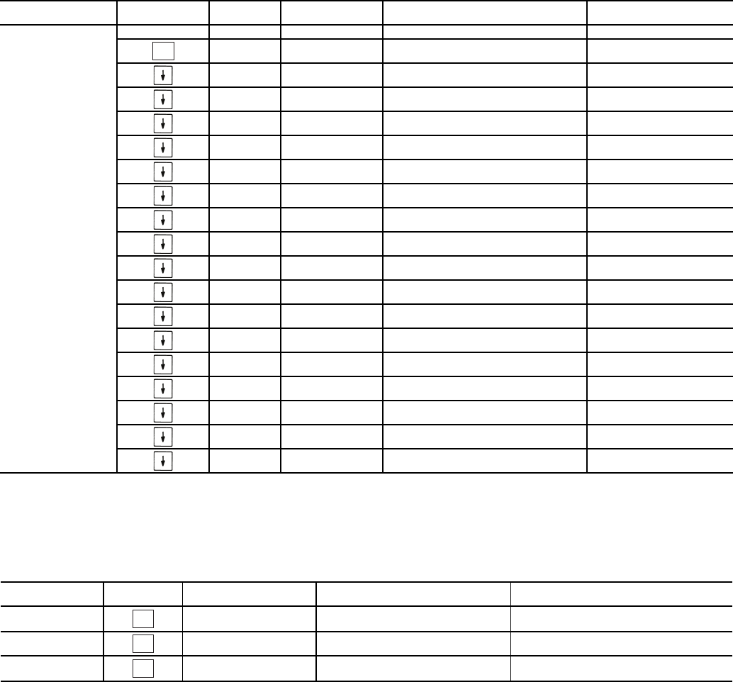
Table 14 — Operating Modes
MODE
NO. ITEM EXPANSION DESCRIPTION
01 CSM CONTROLLING CHILLER Chillervisor System Manager (CSM) is controlling the chiller.
03 MASTER/SLAVE CONTROL Dual Chiller control is enabled.
05
RAMP LOAD LIMITED Ramp load (pull-down) limiting in effect. In this mode, the rate at which leaving fluid temperature
is dropped is limited to a predetermined value to prevent compressor overloading. See Cooling
Ramp Loading (Configuration
SLCT
CRMP). The pull-down limit can be modified, if
desired, to any rate from 0.2° F to 2° F (0.1° to 1° C)/minute.
06
TIMED OVERRIDE IN EFFECT Timed override is in effect. This is a 1 to 4 hour temporary override of the programmed
schedule, forcing unit to Occupied mode. Override can be implemented with unit under
Local (Enable) or CCN (Carrier Comfort Network®) control. Override expires after each use.
07
LOW COOLER SUCTION TEMPA Circuit A cooler Freeze Protection mode. At least one compressor must be on, and the Sat-
urated Suction Temperature is not increasing greater than 1.1° F (0.6° C) in 10 seconds. If
the saturated suction temperature is less than the Brine Freeze Point (Set Points
FRZ
BR.FZ) minus 6° F (3.4° C) and less than the leaving fluid temperature minus 14° F
(7.8° C) for 2 minutes, a stage of capacity will be removed from the circuit. Or, If the satu-
rated suction temperature is less than the Brine Freeze Point minus 14° F (7.8° C), for
90 seconds, a stage of capacity will be removed from the circuit. The control will continue to
decrease capacity as long as either condition exists.
09 SLOW CHANGE OVERRIDE Slow change override is in effect. The leaving fluid temperature is close to and moving
towards the control point.
10 MINIMUM OFF TIME ACTIVE Chiller is being held off by Minutes Off Time (Configuration
OPT2
DELY).
13
DUAL SETPOINT Dual Set Point mode is in effect. Chiller controls to Cooling Set Point 1 (Set Points
COOL
CSP.1) during occupied periods and Cooling Set Point 2 (Set Points
COOL
CSP.2)
during unoccupied periods.
14
TEMPERATURE RESET Temperature reset is in effect. In this mode, chiller is using temperature reset to adjust leav-
ing fluid set point upward and is currently controlling to the modified set point. The set point
can be modified based on return fluid, outdoor-air-temperature, space temperature, or 4 to
20 mA signal.
15
DEMAND LIMITED Demand limit is in effect. This indicates that the capacity of the chiller is being limited by
demand limit control option. Because of this limitation, the chiller may not be able to pro-
duce the desired leaving fluid temperature. Demand limit can be controlled by switch inputs
or a 4 to 20 mA signal.
16
COOLER FREEZE PROTECTION Cooler fluid temperatures are approaching the Freeze point (see Alarms and Alerts section
for definition). The chiller will be shut down when either fluid temperature falls below the
Freeze point.
17
LOW TEMPERATURE COOLING Chiller is in Cooling mode and the rate of change of the leaving fluid is negative and
decreasing faster than -0.5° F per minute. Error between leaving fluid and control point
exceeds fixed amount. Control will automatically unload the chiller if necessary.
18
HIGH TEMPERATURE COOLING Chiller is in Cooling mode and the rate of change of the leaving fluid is positive and increasing.
Error between leaving fluid and control point exceeds fixed amount. Control will automatically
load the chiller if necessary to better match the increasing load.
19 MAKING ICE Chiller is in an unoccupied mode and is using Cooling Set Point 3 (Set Points
COOL
CSP.3) to make ice. The ice done input to the Energy Management Module (EMM) is open.
20 STORING ICE Chiller is in an unoccupied mode and is controlling to Cooling Set Point 2 (Set Points
COOL
CSP.2). The ice done input to the Energy Management Module (EMM) is closed.
21
HIGH SCT CIRCUIT A Chiller is in a Cooling mode and the Saturated Condensing Temperature (SCT) is greater than
the calculated maximum limit. No additional stages of capacity will be added. Chiller capacity
may be reduced if SCT continues to rise to avoid high-pressure switch trips by reducing con-
densing temperature.
23
MINIMUM COMP ON TIME Cooling load may be satisfied, however control continues to operate compressor to ensure
proper oil return. May be an indication of oversized application, low fluid flow rate or low loop
volume.
24
PUMP OFF DELAY TIME Cooling load is satisfied, however cooler pump continues to run for the number of minutes set
by the configuration variable Cooler Pump Shutdown Delay (Configuration
OPT1
PM.DY).
14
CONTROLS
General — The 30MP liquid scroll chillers contain the
ComfortLink™ electronic control system that controls and
monitors all operations of the chiller.
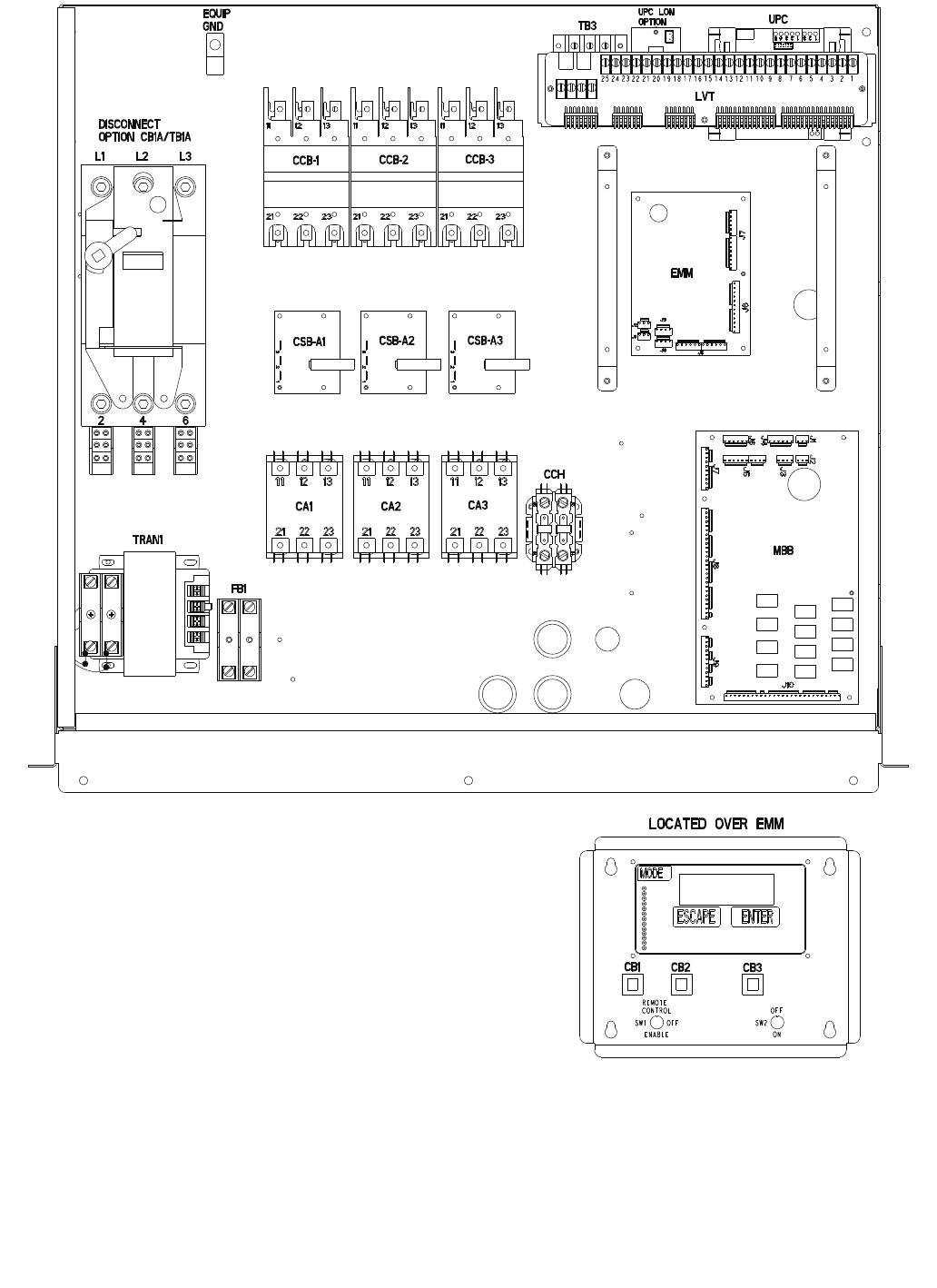
The control system is composed of several components as
listed in the sections below. See Fig. 3 for a typical control box
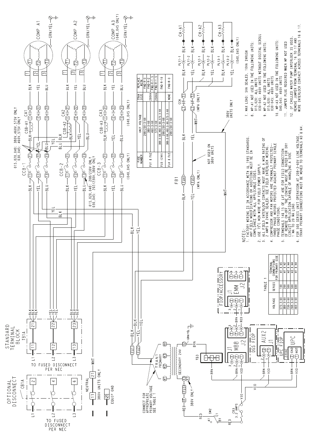
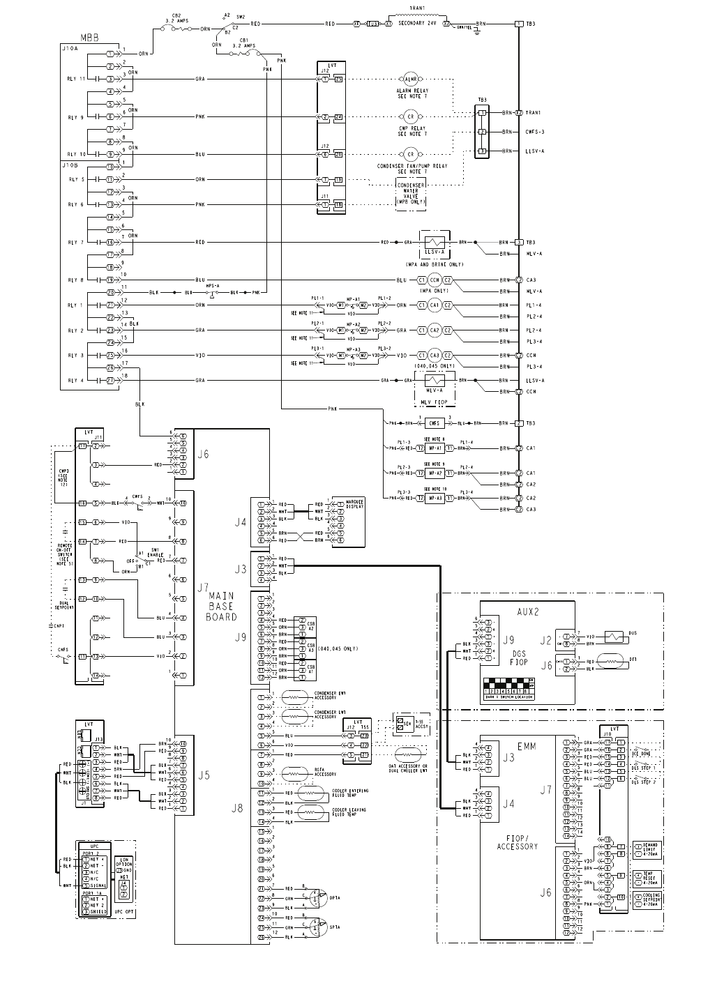
drawing. See Fig. 4 and 5 for control schematics.
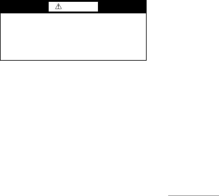
Main Base Board (MBB) — See Fig. 6. The MBB is
the heart of the ComfortLink control system. It contains the
major portion of operating software and controls the operation
of the machine. The MBB continuously monitors input/output
channel information received from its inputs and from all other
modules. The MBB receives inputs from the discharge and
suction pressure transducers and thermistors. See Table 15. The
MBB also receives the feedback inputs from each compressor
current sensor board and other status switches. See Table 16.
The MBB also controls several outputs. Relay outputs con-
trolled by the MBB are shown in Table 17. Information is
transmitted between modules via a 3-wire communication bus
or LEN (Local Equipment Network). The CCN (Carrier Com-
fort Network) bus is also supported. Connections to both LEN
and CCN buses are made at the LVT (low voltage terminal).
Energy Management Module (EMM) — The EMM
module is available as a factory-installed option or as a field-
installed accessory. The EMM module receives 4 to 20 mA
inputs for the leaving fluid temperature reset, cooling set point
and demand limit functions. The EMM module also receives
the switch inputs for the field-installed 2-stage demand limit
and ice done functions. The EMM module communicates the
status of all inputs with the MBB, and the MBB adjusts the
control point, capacity limit, and other functions according to
the inputs received.
Current Sensor Board (CSB) — The CSB is used to
monitor the status of the compressors by measuring current and
providing an analog input to the main base board (MBB).
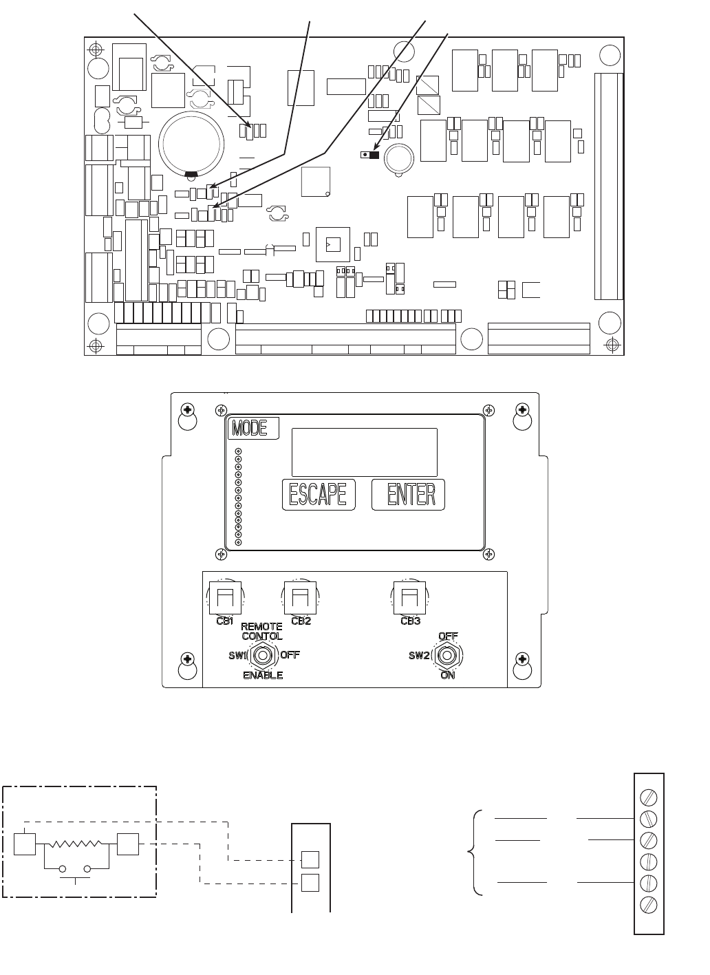
Enable/Off/Remote Contact Switch — The Enable/
Off/Remote Contact switch is a 3-position switch used to
control the chiller. When switched to the Enable position the
chiller is under its own control. Move the switch to the Off
position to shut the chiller down. Move the switch to the
Remote Contact position and a field-installed dry contact can
be used to start the chiller. The contacts must be capable of
handling a 24 vac, 50-mA load. In the Enable and Remote
Contact (dry contacts closed) positions, the chiller is allowed to
operate and respond to the scheduling configuration, CCN
configuration and set point data. See Fig. 7.
Emergency On/Off Switch — The Emergency On/Off
switch should only be used when it is required to shut the
chiller off immediately. Power to the MBB, EMM, and
marquee display is interrupted when this switch is off and all
outputs from these modules will be turned off. See Fig. 7.
Board Addresses — The main base board (MBB) has a
3-position instance jumper that must be set to ‘1.’ The EMM
board has 4-position DIP switches. All switches are set to ‘On’
for all boards except the AUX2 board. The AUX2 board DIP
switch settings are shown on the wiring schematic.
Control Module Communication
RED LED — Proper operation of the control boards can be
visually checked by looking at the red status LEDs
(light-emitting diodes). When operating correctly, the red status
LEDs should be blinking in unison at a rate of once every
2 seconds. If the red LEDs are not blinking in unison, verify
that correct power is being supplied to all modules. Be sure that
the main base board (MBB) is supplied with the current soft-
ware. If necessary, reload current software. If the problem still
persists, replace the MBB. A red LED that is lit continuously or
blinking at a rate of once per second or faster indicates that the
board should be replaced.
GREEN LED — The MBB has one green LED. The Local
Equipment Network (LEN) LED should always be blinking
whenever power is on. All other boards have a LEN LED
which should be blinking whenever power is on. Check LEN
connections for potential communication errors at the board J3
and/or J4 connectors. Communication between modules is
accomplished by a 3-wire sensor bus. These 3 wires run in
parallel from module to module. The J4 connector on the MBB
provides both power and communication directly to the
marquee display only.
YELLOW LED — The MBB has one yellow LED. The
Carrier Comfort Network (CCN) LED will blink during times
of network communication.
Carrier Comfort Network® (CCN) Interface —
The 30MP chiller units can be connected to the CCN if
desired. The communication bus wiring is a shielded,
3-conductor cable with drain wire and is supplied and installed
in the field. See Table 18. The system elements are connected
to the communication bus in a daisy chain arrangement. The
positive pin of each system element communication connector
must be wired to the positive pins of the system elements on
either side of it. This is also required for the negative and
signal ground pins of each system element. Wiring connections
for CCN should be made at LVT. Consult the CCN Contrac-
tor’s Manual for further information.
NOTE: Conductors and drain wire must be 20 AWG (Ameri-
can Wire Gage) minimum stranded, tinned copper. Individual
conductors must be insulated with PVC, PVC/nylon, vinyl,
Teflon, or polyethylene. An aluminum/polyester 100% foil
shield and an outer jacket of PVC, PVC/nylon, chrome vinyl,
or Teflon with a minimum operating temperature range of
–20 C to 60 C is required. Wire manufactured by Alpha (2413
or 5463), American (A22503), Belden (8772), or Columbia
(02525) meets the above mentioned requirements.
It is important when connecting to a CCN communication
bus that a color coding scheme be used for the entire network
to simplify the installation. It is recommended that red be used
for the signal positive, black for the signal negative, and white
for the signal ground. Use a similar scheme for cables contain-
ing different colored wires.
At each system element, the shields of its communication
bus cables must be tied together. If the communication bus is
entirely within one building, the resulting continuous shield
must be connected to a ground at one point only. If the commu-
nication bus cable exits from one building and enters another,
the shields must be connected to grounds at the lightning
suppressor in each building where the cable enters or exits the
building (one point per building only). To connect the unit to
the network:
1. Turn off power to the control box.
2. Cut the CCN wire and strip the ends of the red (+), white
(ground), and black (–) conductors. (Substitute appropri-
ate colors for different colored cables.)
3. Connect the red wire to (+) terminal on LVT of the plug,
the white wire to COM terminal, and the black wire to the
(–) terminal.
4. The RJ14 CCN connector on LVT can also be used, but is
only intended for temporary connection (for example, a
laptop computer running Service Tool).
15
LEGEND FOR FIG. 3-5
ALMR — Alarm Relay
AUX — Auxilliary
C—Contactor, Compressor
CB — Circuit Breaker
CCB — Compressor Circuit Breaker
CH — Crankcase Heater
CCH — Crankcase Heater Relay
COMP — Compressor
CR — Control Relay
CSB — Current Sensor Board
CWFS — Chilled Water Flow Switch
CWP — Chilled Water Pump
DGS — Digital Scroll Compressor
DPT — Discharge Pressure Transducer
DTT — Discharge Temperature Thermistor
DUS — Digital Unloader Solenoid
EMM — Energy Management
EWT — Entering Water Temperature
FB — Fuse Block
FIOP — factory Installed Option
FU — Fuse
GND — Ground
HPS — High-Pressure Switch
LLSV — Liquid Line Solenoid Valve
LON — Local Operating Network
LVT — Low Voltage Terminal
LWT — Leaving Water Temperature
MBB — Main Base Board
MLV — Minimum Load Valve
MP — Modular Motor Protection
NEC — National Electrical Code
OAT — Outdoor-Air Thermistor
PL — Plug
RLY — Relay
SPT — Suction Pressure Transducer
SW — Switch
TB — Terminal Block
TRAN — Transformer
UPC — Unitary Protocol Converter
Terminal Block
Terminal (Unmarked)
Terminal (Marked)
Splice
Factory Wiring
Field Wiring
Accessory or Option Wiring
To indicate common potential only; not to represent wiring.
16
DISCONNECT
OPTION CB1A/TB1A
TRAN1
FB1
CA1 CA2 CA3
CSB-A1 CSB-A2 CSB-A3
CCB-1 CCB-2 CCB-3
CCH
MBB
EMM
LVT
UPC
UPC LON
OPTION
TB3
OFF
ON
SW2
ENABLE
SW1
REMOTE
CONTROL
CB1 CB2 CB3
LOCATED OVER EMM
OFF
L1 L2 L3
1
2
3
4
5
6
7
8
9
10
11
12
13
14
15
16
17
18
19
20
21
22
23
24
25
EQUIP
GND
246
Fig. 3 — Typical Control Box — 30MP015-045 Units
a30-4963
17
COMP A2
TRAN1
H2 H3 H4
SECONDARY 24V
RED
3
3
2
2
1
1
J2
BRN
VIO
22
1
J1
1
33
FU3
SW2
C1
A1
B1
H1
X3
CONNECT FOR
APPROPRIATE
PRIMARY VOLTAGE
SEE TABLE 1
2
4
6
CB1A
11
12
13
TO FUSED
DISCONNECT
PER NEC
OPTIONAL
DISCONNECT
3.2 AMPS
CB3
1
2
3T3
T1
T2
T3
T1
T2
3
2
1
GRN/YEL
GRN/YEL
XF
RED
11 21
12 22
13 23
CA1
BLK
YEL
BLU
11 21
12 22
13 23
CA2
11
12
13
21
22
23
CCB-1
BLK
YEL
BLU
BLK
YEL
BLU
YEL
BLU BLK
YEL
BLU
BLK
11
12
13
21
22
23
CCB-2
BLK
YEL
BLK
015,020,040: 380V,460V,575V ONLY
030,045: 460V,575V ONLY
BLU
YEL
BLU
T3
T1
T2
3
2
1
GRN/YEL
11 21
12 22
13 23
CA3
BLK
YEL
BLU
11
12
13
21
22
23
CCB-3
BLK
YEL
BLU
YEL
BLU
BLK
BLU
BLU
BLU
YEL
YEL
YEL
BLK
BLK
BLK
BLK
YEL
CH-A1
BLK
BLK
BLK
YEL
L1 T1
L2 T2
BLK
YEL
CH-A2
BLK
BLK
BLK
YEL
CH-A3
BLK
BLK
YEL
BLK
015,020,040: 208/230V ONLY
030,045: 202/230V,380V ONLY
MBB
BRN
VIO
2
1
UPC FIOP
UPC
GND
HOT
24VAC
BRN
VIO
12
2
11
1
J1
DGS FIOP
AUX2
BRN
RED
3
3
2
2
1
1J2
2
J1
1
3
FIOP/ACCESSORY
EMM
FU1
BLK
FU2
YEL
GRN/YEL
RED
VIO
VIO
BRN
BRN
PRIMARY
WHT
11
X2
380V
UNITS ONLY
NOT USED ON
380V UNITS
FB1
BLK
YEL
NOTES:
1. FACTORY WIRING IS IN ACCORDANCE WITH UL 1995 STANDARDS.
ANY FIELD MODIFICATIONS OR ADDITIONS MUST BE IN
COMPLIANCE WITH ALL APPLICABLE CODES.
C MIN WIRE FOR FIELD POWER SUPPLY.
3. ALL FIELD INTERLOCK CONTACTS MUST HAVE A MIN RATING OF
2 AMPS @ 24VAC SEALED. SEE FIELD INTERLOCK WIRING.
4. COMPRESSOR AND FAN MOTORS ARE THERMALLY PROTECTED--
THREE PHASE MOTORS PROTECTED AGAINST PRIMARY SINGLE
PHASE CONDITIONS.
5. TERMINALS 14
& 15 OF LVT ARE FOR FIELD CONNECTION
OF REMOTE ON-OFF. THE CONTACT MUST BE RATED FOR DRY
CIRCUIT APPLICATION CAPABLE OF HANDLING A 5VDC
1 MA TO 20 MA LOAD.
6. FOR 500 SERIES UNIT OPERATION AT 208-3-60V LINE VOLTAGE,
TRAN1 PRIMARY CONNECTIONS MUST BE MOVED TO TERMINALS H3 & H4.
8. MP-A1 NOT USED IN THE FOLLOWING UNITS:
015,020: ALL UNITS
9. MP-A2 NOT USED IN THE FOLLOWING UNITS:
015,020: ALL UNITS
10. MP-A3 NOT USED IN THE FOLLOWING UNITS:
11. JUMPER PLUG REQUIRED WHEN MP NOT USED
WHT
(040,045 ONLY)
VOLTAGE SERIES
TERMINAL
CONNECTIONS
FOR PRIMARY SIDE
575-3-60 100 H1 & H5
380-3-60 200 H1 & H2
230-3-60 500 H2 & H4
208-3-60 500 H3 & H4
460-3-60 600 H1 & H4
TABLE 1
7. MAX LOAD: 5VA SEALED, 10VA INRUSH
(040,045 ONLY)
BLK
YEL
(MPA ONLY)
(MPA ONLY)
WHT
BLK
YEL
FU4
FU5
UNIT VOLTAGE REPLACE
WITH
FNQ-R-3
FU1 & FU2
FUSE
NUMBER
380-3-60
TRAN
SIZE
200VA FNQ-R-2
208/230-3-60
FNQ-R-10
FU3 (24V) 380-3-60,460-3-60,575-3-60
250VA
208/230-3-60
460-3-60
575-3-60
FNQ-R-1.5
FNQ-R-1.5
FU4 & FU5 380-3-60,460-3-60,575-3-60 NONE
208/230-3-60
(040,045 ONLY)(040,045 ONLY)
12. IF CHILLED WATER PUMP INTERLOCK IS USED,
REMOVE JUMPER FROM TERMINAL 16 TO 17 AND
WIRE INTERLOCK CONTACT ACROSS TERMINALS 16 & 17.
030-045: 460V UNITS WITHOUT DIGITAL SCROLL
030-045: 460V UNITS
040,045: 460V UNITS
FNQ-R-3
1
2
3
TB3
X1
380V ONLY
PL11-2
PL11-1
PL12-2
PL12-1
CCH
PL13-2
PL13-1
STANDARD
TERMINAL
BLOCK
PER NEC
TO FUSED DISCONNECT
21
22
23
TB1A
EQUIP GND
COMP A1
COMP A3
21
380V UNITS ONLY
NEUTRAL
CSB-A1
CSB-A2
CSB-A3
L1
L2
L3
L1
L2
L3
Fig. 4 — Typical Power Wiring Schematic — 30MP015-045 Units
a30-4965
18
9
9
7
7
8
8
4
6
4
6
RLY 9
5
5
1
3
1
3
RLY 11
2
2
C2C1
C2C1
BLU
3
12
1
10
2
11
4
13
3TB3
SW2
C2
A2
B2
9
18
10
19
8
17
11
12
13
14
20
21
22
23
6
15
7
16
5
14
15
16
17
18
24
25
26
27
3.2 AMPS
CB2
C2C1
RLY 10
J10A
J10B
RLY 5
RLY 6
RLY 7
RLY 8
RLY 1
RLY 2
RLY 3
RLY 4
12
11
10
9
8
7
6
5
4
3
2
1
26
25
24
23
22
17
16
15
14
13
12
11
10
9
8
7
6
10
9
8
7
6
5
4
3
2
1
8
8
3
1
3
1
3
1
6
2
4
2
4
2
12
1
2
3
4
5
6
7
8
9
10
11
1
2
3
4
5
6
12
11
10
9
8
7
J9
21
20
19
18
10
9
8
7
6
5
4
5
4
3
2
1
4
2
1
3
5
RED
BRN
RED
WHT
BLK
RED
WHT
BLK
6
6
5
5
3
3
2
1
RED
1
2
7
7
4
4
J7
C1
A1
B1
OFF
MAIN
BASE
BOARD
J8
9
9
10
10
6
5
4
3
2
1
6
5
4
3
2
1
J6
FIOP/
SPTA
-
+
DPTA
-
+
A
C
B
A
C
B
M1 M2
M1 M2
ORN
GRA
CCH
CA1
CA2
ORN
RED
SEE NOTE 11
SEE NOTE 11
ORN
ORN
ORN
BLK
GRA
PNK
BLU
ORN
PNK
BLU
ORN
GRA
GRA
J5
CSB
A2
2
3
1
RED
ORN
BRN
CSB
A3
2
3
1
RED
ORN
BRN
CSB
A1
2
3
1
RED
ORN
BRN ON
OFF
12345678
DARK = SWITCH LOCATION
DUS
3
2
1
3
2
1
6
5
4
3
2
1
J9
2
1
8
7
2
1
8
7
J2
J6
DTT
RED
WHT
BLK
DGS
MBB
RED
12
11
10
9
8
7
6
5
4
3
2
1
12
11
10
9
8
7
J7
EMM
4
3
2
1
4
3
2
1
J3
4
3
2
1
4
3
2
1
J4
RED
WHT
BLK
RED
WHT
BLK
12
11
10
9
8
7
6
5
4
3
2
1
12
11
10
9
8
7
J6
14
13 14
13
ACCESSORY
1
1
2
3
4
5
6
1
2
3
4
5
6
14
15
4
3
12
13
6
5
10
11
7
8
9
8
6
7
4
59
2
3
10 +
-
COOLING
SETPOINT
4-20mA
RED
3
2
15
13
5
4
16
7
6
17
9
8
10
12
14
LVT
8
1
3
2
5
4
7
6
(+)
(-)
(COM)
SHIELD
LEN CCN
1
2
3
1
2
3
4
5
NET +
NET 2
SHIELD
NET +
NET -
N/C
N/C
SIGNAL
PORT 1A
UPC
PORT 2
J3
1
2
LON
OPTION
GND
J4
NET
UPC OPT
BLK
WHT
RED
RED
BLK
WHT
BLU
VIO
RED
WHT
BLK
RED
BRN
RED
WHT
BLK
REMOTE
ON-OFF
SWITCH
(SEE
NOTE 5)
ENABLE
SW1
GRN
RED
BLK
GRN
RED
BLK
BLU
VIO
RED
BLU
BLU
PNK
ORN
BRN
VIO
+
-
TEMP
RESET
4-20mA
+
-
DEMAND
LIMIT
4-20mA
DLS STEP 2
3.2 AMPS
CB1
TRAN1
SECONDARY 24V
RED FU3 X1
XF BRN
X2
GRN/YEL
LVT
RED
ORN
BRN PL1-4
VIO
BRN
RED
BLK
CH1
-
CH11
-
-
+
G
-
+
G
DLS STEP 1
LVT
16
17
2
1
GRA
GRA
ICE DONE
(040,045 ONLY)
LVT
5
4
3
22
23
21
T-55
ACCSY
SEN
OAT ACCESSORY OR
DUAL CHILLER LWT
CONDENSER EWT
ACCESSORY
CONDENSER LWT
ACCESSORY
BLK
RED COOLER ENTERING
FLUID TEMP
BLK
RED COOLER LEAVING
FLUID TEMP
MLV-A
MLV FIOP
C2C1
M1 M2 VIO CA3
SEE NOTE 11
VIO
BRN LLSV-A
(MPA ONLY)
LLSV-A
RED
(MPA AND BRINE ONLY)
BLK
ORN
ORN
7
6
19
20
118
LVT
2
1
24
25
ALARM RELAY
SEE NOTE 7
ALMR
CWP RELAY
SEE NOTE 7
CR
CONDENSER FAN/PUMP RELAY
SEE NOTE 7
CR
3
44
3
22
11
BLK
WHT
RED
J3
12
11
13
11
14
CWFS
VIO
ORN
CNFS
CNPI
RED
DUAL
SETPOINT
BLU
1
2
3
TB3
CONDENSER
WATER
VALVE
(MPB ONLY)
BRN
FIOP
RGTA
ACCESSORY
CWPI
(SEE
NOTE
12)
T2 T1
MP-A1
T2 T1
MP-A2
T2 T1
MP-A3
CWFS
SEE NOTE 8
SEE NOTE 9
SEE NOTE 10
ORN
1TB3
PNK
PNK
BLK
BRN PL2-4
BRN MLV-A
BRN TRAN1
X2
BRN CWFS-3
3
44
3
22
11
BLK
WHT
RED MARQUEE
DISPLAY
66
55
RED
BRN
J4
1
2
3
4
5
6
1
2
3
4
5
6
BLK
WHT
RED
BRN
RED
BRN MLV-A
BRN CA3
C2
BRN PL2-4
BRN PL3-4
BRN PL3-4
BRN CCH
C2
BRN CCH
C2
PNK
2TB3
BRN
BRN CA1
C2
BRN CA1
C2
BRN CA2
C2
BRN CA2
C2
BRN CA3
C2
(040,045 ONLY)
BRN LLSV-A
MP-A1
VIO
VIO
PL1-2PL1-1
VIO
MP-A2
VIO
VIO
PL2-2PL2-1
VIO
J13
J1
J11
J10
J12 T55
BRN
GRA
GRA
MP-A3
VIO
VIO
PL3-2PL3-1
VIO
PNK
BLK
BLK
HPS-A
J11
J12
J12
BLK
4
WHT
2
BRN
GRA
RED
PL1-3
PNK RED
PL1-4
BRN
PL2-3
PNK RED
PL3-3
PNK RED
PNK BRN
PL2-4
BRN
PL3-4
BRN
BRN
BLU
31
AUX2
Fig. 5 — Typical Control Wiring Schematic — 30MP015-045 Units a30-4966
19
Table 15 — Thermistor Designations
LEGEND
Table 16 — Status Inputs
Table 17 — Output Relays
Table 18 — CCN Communication Bus Wiring
Sensors — The electronic control uses 2 to 7 thermistors to
sense temperatures for controlling chiller operation. See
Table 15. These sensors are outlined below. Thermistors
RGTA, CNDE, CNDL, EWT, LWT, and OAT are identical in
temperature versus resistance and voltage drop performance.
The dual chiller thermistor (DLWT) is 5 k at 77 F (25 C)
thermistor. Space temperature thermistor (SPT) is a 10 kat
77 F (25 C). See Thermistors section for temperature-resis-
tance-voltage drop characteristics.
COOLER LEAVING FLUID SENSOR (LWT) — The thermis-
tor is installed in a well in the factory-installed leaving fluid
piping coming from the bottom of the brazed-plate heat
exchanger.
COOLER ENTERING FLUID SENSOR (EWT) — The therm-
istor is installed in a well in the factory-installed entering fluid
piping coming from the top of the brazed-plate heat exchanger.
CONDENSER LEAVING FLUID SENSOR (CNDL) — The
thermistor is installed in a well in the factory-installed leaving
fluid piping coming from the bottom of the brazed-plate heat
exchanger.
COOLER ENTERING FLUID SENSOR (CNDE) — The therm-
istor is installed in a well in the factory-installed entering fluid
piping coming from the top of the brazed-plate heat exchanger.
COMPRESSOR RETURN GAS TEMPERATURE SEN-
SOR (RGTA) — This accessory thermistor can be installed in
a well located in the suction line.
OUTDOOR-AIR TEMPERATURE SENSOR (OAT) —
This sensor is an accessory that is remotely mounted and used
for outdoor air temperature reset. See Table 15.
DUAL LEAVING WATER TEMPERATURE SENSOR
(DLWT) — This input can be connected to the LVT. See Ta-
ble 15. For dual chiller applications (parallel only are support-
ed), connect the dual chiller leaving fluid temperature sensor
(5 kthermistor, Carrier part no. HH79NZ029) to the outside
air temperature input of the Master chiller. If outside air tem-
perature is required for reset applications, connect the sensor to
the Slave chiller and configure the slave chiller to broadcast the
value to the Master chiller.
REMOTE SPACE TEMPERATURE SENSOR (SPT) —
The sensor (part no. 33ZCT55SPT) is an accessory sensor that
is remotely mounted in the controlled space and used for space
temperature reset. The sensor should be installed as a wall-
mounted thermostat would be (in the conditioned space where
it will not be subjected to either a cooling or heating source or
direct exposure to sunlight, and 4 to 5 ft above the floor).
Space temperature sensor wires are to be connected to
terminals in the unit main control box. The space temperature
sensor includes a terminal block (SEN) and a RJ11 female
connector. The RJ11 connector is used access into the Carrier
Comfort Network® (CCN) at the sensor.
To connect the space temperature sensor (Fig. 8):
1. Using a 20 AWG twisted pair conductor cable rated for
the application, connect 1 wire of the twisted pair to one
SEN terminal and connect the other wire to the other
SEN terminal located under the cover of the space
temperature sensor.
2. Connect the other ends of the wires to terminals 3 and 4
on LVT located in the unit control box.
Units on the CCN can be monitored from the space at the
sensor through the RJ11 connector, if desired. To wire the RJ11
connector into the CCN (Fig. 9):
1. Cut the CCN wire and strip ends of the red (+), white
(ground), and black (–) conductors. (If another wire color
scheme is used, strip ends of appropriate wires.)
IMPORTANT: A shorted CCN bus cable will prevent some
routines from running and may prevent the unit from start-
ing. If abnormal conditions occur, unplug the connector. If
conditions return to normal, check the CCN connector and
cable. Run new cable if necessary. A short in one section of
the bus can cause problems with all system elements on the
bus.
THERMISTOR
PIN
CONNECTION
POINT
THERMISTOR INPUT
CLWT J8-13,14 (MBB) Cooler Leaving Fluid
CEWT J8-11,12 (MBB) Cooler Entering Fluid
RGTA J8-9,10 (MBB) Circuit A Return Gas
Temperature (accessory)
OAT
J8-6,7 (MBB),
LVT 4,13
Outdoor-Air Temperature
Sensor (accessory) or Dual
LWT Sensor
SPT J8-5,6 (MBB)
LVT-3 , 4
Accessory Remote Space
Temperature Sensor
CNDE J8-1,2 Condenser Entering Water
Temperature Sensor
CNDL J8-3,4 Condenser Leaving Water
Temperature Sensor
LWT — Leaving Water Temperature
MBB — Main Base Board
STATUS SWITCH PIN CONNECTION POINT
Condenser Flow Switch LVT-11,17, J7-2, J6-2
Dual Set Point LVT-12,13, J7-3,4
Remote On/Off LVT-14,15
Cooler Flow Switch Interlock LVT-16,17, J6-2, J7-10
Compressor Fault Signal, A1 J9-11,12
Compressor Fault Signal, A2 J9-5,6
Compressor Fault Signal, A3 J9-8,9
RELAY
NO. DESCRIPTION
K1 Energize Compressor A1
K2 Energize Compressor A2
K3 Energize Compressor A3
K4 Energize Minimum Load Valve
K5 Water Valve Open
K6 Water Valve Close
K7 Liquid Line Solenoid Valve
K8 Crankcase Heater Relay (30MPA Only)
K9 Chilled Water Pump
K10 Condenser Fan/Pump
K11 Alarm Relay
MANUFACTURER PART N O.
Regular Wiring Plenum Wiring
Alpha 1895 —
American A21451 A48301
Belden 8205 884421
Columbia D6451 —
Manhattan M13402 M64430
Quabik 6130 —
IMPORTANT: The cable selected for the RJ11 connector
wiring MUST be identical to the CCN communication bus
wire used for the entire network. Refer to Table 18 for
acceptable wiring.
20
CEPL130346-01
STATUS
LEN
J1 J2
J4 J3
J5
J6
J7 J8 J9
J10
CCN
RED LED - STATUS GREEN LED -
LEN (LOCAL EQUIPMENT NETWORK)
YELLOW LED -
CCN (CARRIER COMFORT NETWORK)
INSTANCE JUMPER
K11 K10 K9
K8 K7 K6 K5
K4 K3 K2 K1
Fig. 6 — Main Base Board
Fig. 7 — Enable/Off/Remote Contact Switch, and Emergency On/Off Switch Locations
SPT (T10) PART NO. 33ZCT55SPT
SENSOR
SEN SEN LVT
3
4
Fig. 8 — Typical Space Temperature
Sensor Wiring
T-55 SPACE
SENSOR
CCN+
CCN GND
CCN-
TO CCN
COMM 1
BUS (PLUG)
AT UNIT
1
2
3
4
5
6
Fig. 9 — CCN Communications Bus Wiring
to Optional Space Sensor RJ11 Connector
a30-4967
a30-4968
21
2. Insert and secure the red (+) wire to terminal 5 of the
space temperature sensor terminal block.
3. Insert and secure the white (ground) wire to terminal 4 of
the space temperature sensor.
4. Insert and secure the black (–) wire to terminal 2 of the
space temperature sensor.
5. Connect the other end of the communication bus cable to
the remainder of the CCN communication bus.
Energy Management Module (Fig. 10) — This
factory-installed option (FIOP) or field-installed accessory is
used for the following types of temperature reset, demand
limit, and/or ice features:
• 4 to 20 mA leaving fluid temperature reset (requires
field-supplied 4 to 20 mA generator)
• 4 to 20 mA cooling set point reset (requires field-
supplied 4 to 20 mA generator)
• Discrete inputs for 2-step demand limit (requires field-
supplied dry contacts capable of handling a 24 vac,
50 mA load)
• 4 to 20 mA demand limit (requires field-supplied 4 to
20 mA generator)
• Discrete input for Ice Done switch (requires field-
supplied dry contacts capable of handling a 24 vac,
50 mA load)
See Demand Limit and Temperature Reset sections on
pages 27 and 31 for further details.
Loss-of-Cooler Flow Protection — A proof-of-
cooler flow device is factory installed in all chillers.
Condenser Flow Protection — A proof-of-condens-
er flow protection accessory can be field installed in the con-
denser water piping of all chillers. The unit must be configured
for the input to be enabled.
Thermostatic Expansion Valves (TXV) — All
units are equipped from the factory with conventional TXVs.
The 30MPA units and 30MPW units with medium temperature
brine also have factory-installed liquid line solenoids. The liq-
uid line solenoid valves are not intended to be a mechanical
shut-off. For 30MPW units, when service is required, reclaim
the refrigerant from the system.
For 30MPA units when service is required, the compressor
and evaporator can be serviced by closing the factory-installed
liquid line service valve and field-installed discharge line ser-
vice valve. After the valves are closed, reclaim the refrigerant
from the system.
The TXV is set at the factory to maintain approximately 8 to
12° F (4.4 to 6.7° C) suction superheat leaving the cooler by
monitoring the proper amount of refrigerant into the cooler. All
TXVs are adjustable, but should not be adjusted unless abso-
lutely necessary.
Capacity Control — The control system cycles com-
pressors, digital scroll modulting solenoid (if equipped), and
minimum load valve solenoids (if equipped) to maintain the
user-configured leaving chilled fluid temperature set point. En-
tering fluid temperature is used by the main base board (MBB)
to determine the temperature drop across the cooler and is used
in determining the optimum time to add or subtract capacity
stages. The chilled fluid temperature set point can be automati-
cally reset by the return fluid temperature, space, or outdoor-air
temperature reset features. It can also be reset from an external
4 to 20-mA signal (requires energy management module FIOP
or accessory).
The capacity control algorithm runs every 30 seconds. The
algorithm attempts to maintain the Control Point at the desired
set point. Each time it runs, the control reads the entering and
leaving fluid temperatures. The control determines the rate at
which conditions are changing and calculates 2 variables based
on these conditions. Next, a capacity ratio is calculated using
the 2 variables to determine whether or not to make any
changes to the current stages of capacity. This ratio value
ranges from –100 to +100%. If the next stage of capacity is a
compressor, the control starts (stops) a compressor when the
ratio reaches +100% (–100%). If installed, the minimum load
valve solenoid will be energized with the first stage of capacity.
Minimum load valve value is a fixed 30% in the total capacity
calculation. The control will also use the minimum load valve
solenoid as the last stage of capacity before turning off the last
compressor. A delay of 90 seconds occurs after each capacity
step change. Refer to Table 19.
MINUTES LEFT FOR START — This value is displayed
only in the network display tables (using Service Tool,
ComfortVIEW™ or ComfortWORKS® software) and
represents the amount of time to elapse before the unit will start
its initialization routine. This value can be zero without the
machine running in many situations. This can include being
unoccupied, ENABLE/OFF/REMOTE CONTACT switch in
the OFF position, CCN not allowing unit to start, Demand
Limit in effect, no call for cooling due to no load, and alarm or
alert conditions present. If the machine should be running and
none of the above are true, a minimum off time (DELY, see
below) may be in effect. The machine should start normally
once the time limit has expired.
MINUTES OFF TIME (Configuration
OPT2
DELY) — This user-configurable time period is used by the
control to determine how long unit operation is delayed after
power is applied/restored to the unit. Typically, this time period
is configured when multiple machines are located on a single
site. For example, this gives the user the ability to prevent all
the units from restarting at once after a power failure. A value
of zero for this variable does not mean that the unit should be
running.
LEAD/LAG DETERMINATION — This is a configurable
choice and is factory set to be automatic for all units unless the
unit is equipped with minimum load, then circuit A is lead
(Configuration
OPT2
LLCS). The value can be changed
to Circuit A or Circuit B leading as desired. Set at automatic,
the control will sum the current number of logged circuit starts
and one-quarter of the current operating hours for each circuit.
The circuit with the lowest sum is started first. Changes to
which circuit is the lead circuit and which is the lag are also
made when total machine capacity is at 100% or when there is
a change in the direction of capacity (increase or decrease) and
each circuit’s capacity is equal.
CAPACITY CONTROL OVERRIDES — The following over-
rides will modify the normal operation of the routine.
Deadband Multiplier — The user configurable Deadband
Multiplier (Configuration
SLCT
Z.GN) has a default
value of 1.0. The range is from 1.0 to 4.0. When set to other
than 1.0, this factor is applied to the capacity Load/Unload
Factor. The larger this value is set, the longer the control will
delay between adding or removing stages of capacity. Figure
11 shows how compressor starts can be reduced over time if
the leaving water temperature is allowed to drift a larger
amount above and below the set point. This value should be set
in the range of 3.0 to 4.0 for systems with small loop volumes.
Figure 12 shows the operating envelope for the compressor.
CAUTION
Care should be taken when interfacing with other manufac-
turer’s control systems due to possible power supply
differences, full wave bridge versus half wave rectification.
The two different power supplies cannot be mixed.
ComfortLink™ controls use half wave rectification. A
signal isolation device should be utilized if a full wave
bridge signal generating device is used.
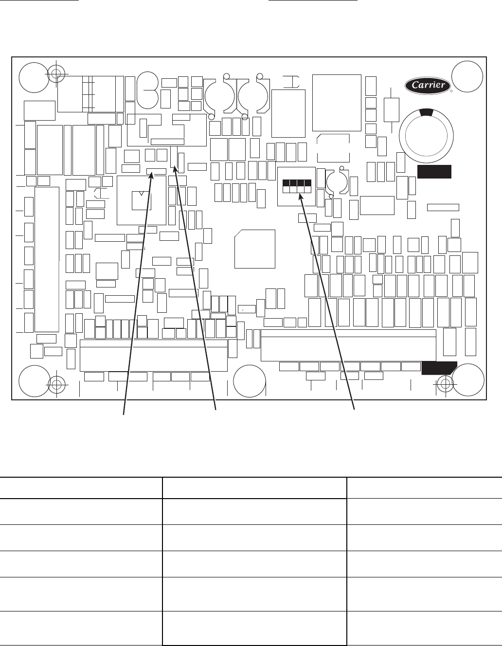
22
First Stage Override — If the current capacity stage is zero,
the control will modify the routine with a 1.2 factor on adding
the first stage to reduce cycling. This factor is also applied
when the control is attempting to remove the last stage of
capacity.
Slow Change Override — The control prevents the capacity
stages from being changed when the leaving fluid temperature
is close to the set point (within an adjustable deadband) and
moving towards the set point.
Table 19 — Part Load Data Percent Displacement, Standard Units with Minimum Load Valve
*Hot gas bypass (minimum load) valve energized. NOTE: These capacity steps may vary due to different capacity
staging sequences.
30MP UNIT SIZE CONTROL
STEPS
CAPACITY STEPS
(% Displacement)
015
1
2
3
18*
50
100
020
1
2
3
25*
50
100
030
1
2
3
34*
50
100
040
1
2
3
4
21*
33
67
100
045
1
2
3
4
22*
33
67
100
CEBD430351-0396-01C
TEST 1
CEPL130351-01
PWR
TEST 2
J1 J2
J4 J3
J5
J6
J7
LEN
STATUS
RED LED - STATUS GREEN LED -
LEN (LOCAL EQUIPMENT NETWORK) ADDRESS
DIP SWITCH
Fig. 10 — Energy Management Module
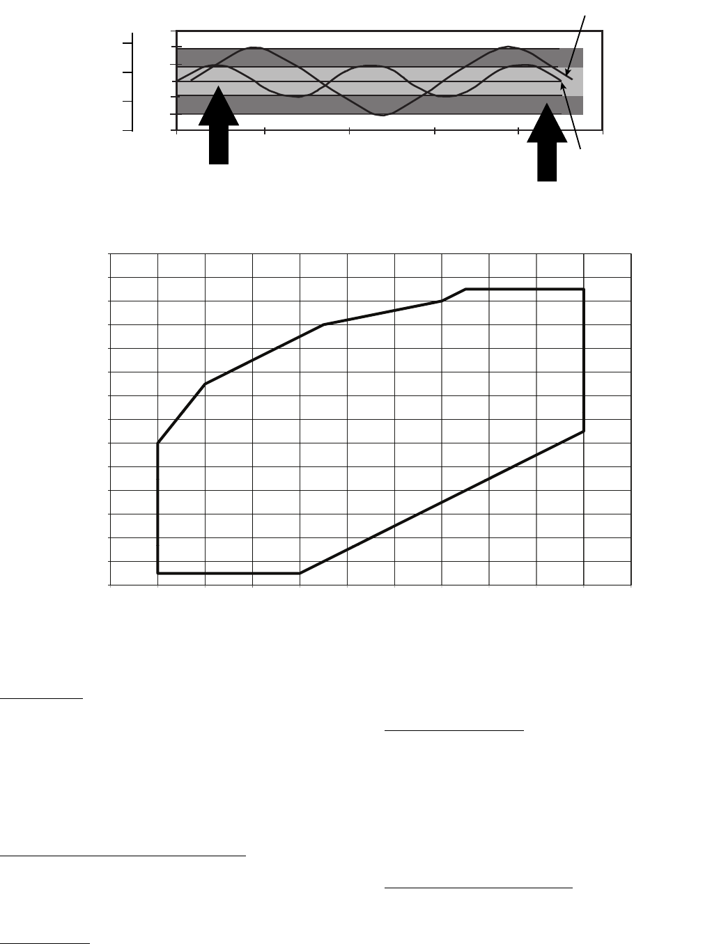
23
Ramp Loading — Ramp loading (Configura-
tion
SLCT
CRMP) limits the rate of change of leaving
fluid temperature. If the unit is in a Cooling mode and config-
ured for Ramp Loading, the control makes 2 comparisons be-
fore deciding to change stages of capacity. The control calcu-
lates a temperature difference between the control point and
leaving fluid temperature. If the difference is greater than 4° F
(2.2° C) and the rate of change (°F or °C per minute) is more
than the configured Cooling Ramp Loading value (CRMP),
the control does not allow any changes to the current stage of
capacity.
Low Entering Fluid Temperature Unloading — When the
entering fluid temperature is below the control point, the
control will attempt to remove 25% of the current stages being
used. If exactly 25% cannot be removed, the control removes
an amount greater than 25% but no more than necessary. The
lowest stage will not be removed.
Hot Gas Bypass — If equipped, the hot gas bypass valve is
energized only when one compressor is running on circuit A. If
the close control feature is enabled the hot gas bypass valve
may be used as needed to obtain leaving fluid temperature
close to set point.
Cooler Freeze Protection — The control will try to prevent
shutting the chiller down on a Cooler Freeze Protection alarm
by removing stages of capacity. If the cooler fluid selected
is Water, the freeze point is 34 F (1.1 C). If the cooler fluid
selected is Brine, the freeze point is the Brine Freeze Point (Set
Points
FRZ
BR.FZ). This alarm condition (A207) only
references leaving fluid temperature and NOT Brine Freeze
point. If the cooler leaving fluid temperature is less than the
freeze point plus 2.0° F (1.1° C), the control will immediately
remove one stage of capacity. This can be repeated once every
30 seconds.
Low Saturated Suction Protection — The control will try to
prevent shutting a circuit down due to low saturated suction
conditions by removing stages of capacity. The circuit alert
condition (T116) compares saturated suction temperature to the
configured Brine Freeze Point (Set Points
FRZ
BR.FZ).
The Brine Freeze point is a user-configurable value that must
be left at 34 F (1.1 C) for 100% water systems. A lower value
47
46
45
44
43
42
41
0 200 400 600 800 1000
TIME (SECONDS)
2 STARTS
3 STARTS
DEADBAND EXAMPLE
LWT (F)
MODIFIED
DEADBAND
STANDARD
DEADBAND
8
7
6
5
LWT (C)
LEGEND
LWT — Leaving Water Temperature
Fig. 11 — Deadband Multiplier
1
60
170
130
140
150
160
110
120
130
80
90
100
50
60
70
30
40
-30 -20 -10 0 10 20 304050607080
SCT (F)
SST (F)
LEGEND
Fig. 12 — Operating Envelope for R-410A Compressor
SCT — Saturated Condensing Temperature
SST — Saturated Suction Temperature
a30-4969
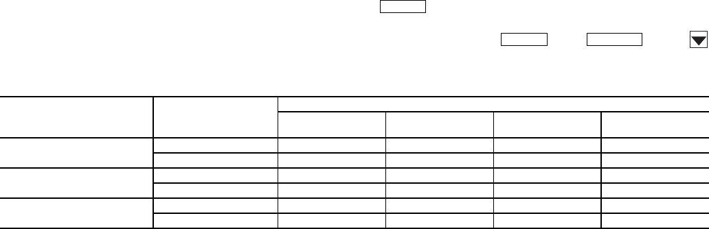
24
may be entered for systems with brine solutions, but this value
should be set according to the freeze protection level of the
brine mixture. Failure to properly set this brine freeze point val-
ue may permanently damage the brazed plate heat exchanger.
The control will initiate Mode 7 (Circuit A) to indicate a cir-
cuit’s capacity is limited and that eventually the circuit may
shut down.
Operation of Machine Based on Control
Method and Cooling Set Point Selection Set-
tings — Machine On/Off control is determined by the
configuration of the Control Method (Configuration
OPT2
CTRL) and Cooling Set Point Select
(Configuration
SLCT
CLSP) variables. All units are fac-
tory configured with Cooling Set Point Select set to 0 (single
set point). With the control method set to 0, simply switching
the Enable/Off/Remote Contact switch to the Enable or
Remote Contact position (external contacts closed) will put the
chiller in an occupied state. The control mode (Run
Status
VIEW
STAT) will be 1 (OFF LOCAL) when the
switch is Off and will be 5 (ON LOCAL) when in the Enable
position or Remote Contact position with external contacts
closed.
Two other control methods are available for Machine On/
Off control:
OCCUPANCY SCHEDULE (Configuration
OPT2
CTRL = 1) — The main base board will use the operating
schedules as defined under the Time Clock mode in the scroll-
ing marquee display. These schedules are identical. The sched-
ule number must be set to 1 for local schedule.
The schedule number can be set anywhere from 65 to 99
for operation under a CCN global schedule. The Enable/Off/
Remote Contact must be in the Enable or Remote Contact posi-
tion. The control mode (Run Status
VIEW
STAT) will be
1 when the switch is Off. The control mode will be 3 when the
Enable/Off/Remote Contact switch input is On and the time of
day is during an unoccupied period. Similarly, the control
mode will be 7 when the time of day is during an occupied
period.
CCN SCHEDULE (Configuration
OPT2
CTRL =
2) — An external CCN device such as Chillervisor System
Manager controls the On/Off state of the machine. This CCN
device forces the variable ‘CHIL_S_S’ between Start/Stop to
control the chiller. The control mode (Run Status
VIEW
STAT) will be 1 when the switch is Off. The con-
trol mode will be 2 when the Enable/Off/Remote Contact
switch input is On and the CHIL_S_S variable is ‘Stop.’
Similarly, the control mode will be 6 when the CHIL_S_S vari-
able is ‘Start.’
Table 20 illustrates how the control method and cooling set
point select variables direct the operation of the chiller and the
set point to which it controls. The illustration also shows the
ON/OFF state of the machine for the given combinations.
Cooling Set Point Select
SINGLE — Unit operation is based on Cooling Set Point 1
(Set Points
COOL
CSP.1).
DUAL SWITCH — Unit operation is based on Cooling Set
Point 1 (Set Points
COOL
CSP.1) when the Dual Set
Point switch contacts are open and Cooling Set Point 2 (Set
Points
COOL
CSP.2) when they are closed.
DUAL CCN OCCUPIED — Unit operation is based on
Cooling Set Point 1 (Set Points
COOL
CSP.1) during the
Occupied mode and Cooling Set Point 2 (Set
Points
COOL
CSP.2) during the Unoccupied mode as
configured under the local occupancy schedule accessible only
from CCN. Schedule Number in Table SCHEDOVR (See Ap-
pendix B) must be configured to 1. If the Schedule Number is
set to 0, the unit will operate in a continuous 24-hr Occupied
mode. Control method must be configured to 0 (switch). See
Table 20.
4 TO 20 mA INPUT — Unit operation is based on an external
4 to 20 mA signal input to the Energy Management Module
(EMM).
Cooler Pump Control — The AquaSnap® 30MP ma-
chines are configured with the Cooler Pump Control (Configu-
ration
OPT1
CPC) = ON.
The maximum load allowed for the Chilled Water Pump
Starter is 5 VA sealed, 10 VA inrush at 24 volts. The starter coil
is powered from the chiller control system. The starter should
be wired between LVT 24 and TB3-1. If equipped, the field-in-
stalled chilled water pump starter auxiliary contacts should be
connected in series with the chilled water flow switch between
LVT 16 and LVT 17.
Ice Mode — When Ice Mode is enabled Cooling Setpoint
Select must be set to Dual Switch, Dual 7 day or Dual CCN
Occupied and the Energy Management Module (EMM) must
be installed. Unit operation is based on Cooling Setpoint 1
(CSP.1) during the Occupied mode, Ice Setpoint (CSP.3) dur-
ing the Unoccupied mode with the Ice Done contacts open and
Cooling Setpoint 2 (CSP.2) during the Unoccupied mode with
the Ice Done contacts closed. These 3 set points can be utilized
to develop your specific control strategy.
Service Test (See Table 4) — Both main power and
control circuit power must be on.
The Service Test function should be used to verify proper
operation of condenser output, compressors, minimum load
valve solenoid (if installed), cooler pump, and remote alarm re-
lay. To use the Service Test mode, the Enable/Off/Remote Con-
tact switch must be in the OFF position. Use the display keys
and Table 4 to enter the mode and display TEST. Press
twice so that OFF flashes. Enter the password if re-
quired. Use either arrow key to change the TEST value to the
ON position and press . Press and the
button to enter the OUTS or COMP sub-mode.
Table 20 — Control Methods and Cooling Set Points
*Dual set point switch input used. CSP1 used when switch input is open. CSP2 used when switch input is closed.
†Cooling set point determined from 4 to 20 mA input to energy management module (EMM) to terminals TB6-3,5.
ENTER
ENTER
ESCAPE
CONTROL
TYPE
(CTRL)
OCCUPANCY
STATE
COOLING SET POINT SELECT (CLSP)
0
(single)
1
(dual, switch)
2
(dual, occ)
3
(4 to 20 mA)
0 (switch) Occupied ON,CSP1 ON* ON,CSP1 ON†
Unoccupied ON,CSP1 ON* ON,CSP2 ON
2 (Occupancy) Occupied ON,CSP1 ON* Illegal ON†
Unoccupied OFF OFF Illegal OFF
3 (CCN) Occupied ON,CSP1 ON* ON,CSP1 ON†
Unoccupied ON,CSP1 ON* ON,CSP2 ON†
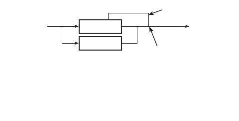
25
Test the condenser output, cooler pump, liquid line solenoid
valve (30MPA only), crankcase heater, water valve (accesso-
ry), and alarm relay by changing the item values from OFF to
ON. These discrete outputs are then turned off if there is no
keypad activity for 10 minutes. When testing compressors,
lead compressor must be started first. All compressor outputs
can be turned on, but the control will limit the rate by staging
one compressor per minute. Minimum load valve can be tested
with the compressors on or off. The relays under the COMP
mode will stay on for 10 minutes if there is no keypad activity.
Compressors will stay on until they are turned off by the opera-
tor. The Service Test mode will remain enabled for as long as
there is one or more compressors running. All safeties are mon-
itored during this test and will turn a compressor, circuit or the
machine off if required. Any other mode or sub-mode can be
accessed, viewed, or changed during the TEST mode. The
STAT item (Run Status
VIEW) will display “0” as long as
the Service mode is enabled. The TEST sub-mode value must
be changed back to OFF before the chiller can be switched to
Enable or Remote contact for normal operation.
Cooler Pump Sequence of Operation — At any-
time the unit is in an ON status, as defined by the one of the
following conditions, the cooler pump relay will be enabled.
1. The Enable-Off-Remote Switch in ENABLE,
(CTRL=0).
2. Enable-Off-Remote Switch in REMOTE with a
Start-Stop remote contact closure (CTRL=0).
3. An Occupied Time Period from an Occupancy Schedule
in combination with items 1 or 2 (CTRL=2).
4. A CCN Start-Stop Command to Start in combination
with items 1 or 2 (CTRL=3).
There are certain alarm conditions and Operating Modes
that will turn the cooler pump relay ON. This sequence will de-
scribe the normal operation of the pump control algorithm.
When the unit cycles from an "On" state to an "Off' state,
the cooler pump output will remain energized for the Cooler
Pump Shutdown Delay (Configuration
OPT1
PM.DY).
This is configurable from 0 to 10 minutes. The factory default
is 1 minute. If the pump output was deenergized during the
transition period, the pump output will not be energized.
The Cooler Pump Relay will be energized when the ma-
chine is "On." The chilled water pump interlock circuit consists
of a chilled water flow switch and a field-installed chilled water
pump interlock. If the chilled water pump interlock circuit does
not close within five (5) minutes of starting, an A200 - Cooler
Flow/Interlock failed to close at Start-Up alam1 will be gener-
ated and chiller will not be allowed to start.
If the chilled water pump interlock or chilled water flow
switch opens for at least three (3) seconds after initially being
closed, an A201 - Cooler Flow 1 Interlock Contacts Opened
During Normal Operation alarm will be generated and the ma-
chine will stop.
Condenser Pump/Condenser Fan Output Con-
trol — The main base board (MBB) has the capability to
control either a condenser fan output or a condenser pump out-
put depending on the unit configuration.
If the unit is configured for Configuration
UNIT
TYPE = 2 (air cooled), then the output will be off as
long as capacity is equal to 0 and will be energized 5 seconds
before a compressor is started and remain energized until ca-
pacity is 0 again.
If the unit is configured for Configuration
UNIT
TYPE = 3 (water cooled), then the output will be used
for consenser pump control and additional configuration is re-
quired. To enable the condenser pump control use Configura-
tion
OPT1
DPME. The pump can be configured for no
pump control, on when occupied, and on when capacity is
greater than 0.
Configuring and Operating Dual Chiller Con-
trol — The dual chiller routine is available for the control of
two units supplying chilled fluid on a common loop. This
control algorithm is designed for parallel fluid flow arrangement
only. One chiller must be configured as the master chiller, the
other as the slave. An additional leaving fluid temperature
thermistor (Dual Chiller LWT) must be installed as shown in
Fig. 13 and 14 and connected to the master chiller. Refer to Sen-
sors section, page 19, for wiring. The CCN communication bus
must be connected between the two chillers. Connections can be
made to the CCN screw terminals on LVT. Refer to Carrier
Comfort Network® Interface section, page 14, for wiring infor-
mation. Configuration examples are shown in Tables 21 and 22.
Refer to Table 21 for dual chiller configuration. In this
example the master chiller will be configured at address 1 and
the slave chiller at address 2. The master and slave chillers
must reside on the same CCN bus (Configuration
CCN
CCNB) but cannot have the same CCN address (Configu-
ration
CCN
CCNA). Both master and slave chillers must
have Lead/Lag Chiller Enable (Configuration
RSET
LLEN) configured to ENBL. Master/Slave Select (Config-
uration
RSET
MSSL) must be configured to MAST for
the master chiller and SLVE for the slave. Also in this example,
the master chiller will be configured to use Lead/Lag Balance
Select (Configuration
RSET
LLBL) and Lead/Lag Bal-
ance Delta (Configuration
RSET
LLBD) to even out the
chiller run-times weekly. The Lag Start Delay (Configura-
tion
RSET
LLDY) feature will be set to 10 minutes. This
will prevent the lag chiller from starting until the lead chiller
has been at 100% capacity for the length of the delay time. Par-
allel configuration (Configuration
RSET
PARA) can
only be configured to YES. The variables LLBL, LLBD and
LLDY are not used by the slave chiller.
Dual chiller start/stop control is determined by configura-
tion of Control Method (Configuration
OPT1
CTRL) of
the Master chiller. The Slave chiller should always be config-
ured for CTRL=0 (Switch). If the chillers are to be controlled
by Remote Contacts, both Master and Slave chillers should be
enabled together. Two separate relays or one relay with
two sets of contacts may control the chillers. The Enable/Off/
Remote Contact switch should be in the Remote Contact
position on both the Master and Slave chillers. The Enable/Off/
Remote Contact switch should be in the Enable position for
CTRL=2 (Occupancy) or CTRL=3 (CCN Control).
Both chillers will stop if the Master chiller Enable/Off/
Remote Contact switch is in the Off position. If the Emergency
Stop switch is turned off or an alarm is generated on the Master
chiller the Slave chiller will operate in a Stand-Alone mode.
If the Emergency Stop switch is turned off or an alarm is
generated on the Slave chiller the Master chiller will operate in
a Stand-Alone mode.
The master chiller controls the slave chiller by changing its
Control Mode (Run Status
VIEW
STAT) and its operat-
ing setpoint or Control Point (Run Status
VIEW
CT.PT).
MASTER
CHILLER
SLAVE
CHILLER
LEAVING
FLUID
RETURN
FLUID
THERMISTOR
WIRING*
INSTALL DUAL CHILLER LWT
LEAVING FLUID TEMPERATURE
THERMISTOR (T10) HERE
*Depending on piping sizes, use either:
• HH79NZ014 sensor/10HB50106801 well (3-in. sensor/well)
• HH79NZ029 sensor/10HB50106802 well (4-in. sensor/well)
Fig. 13 — Dual Chiller Thermistor Location
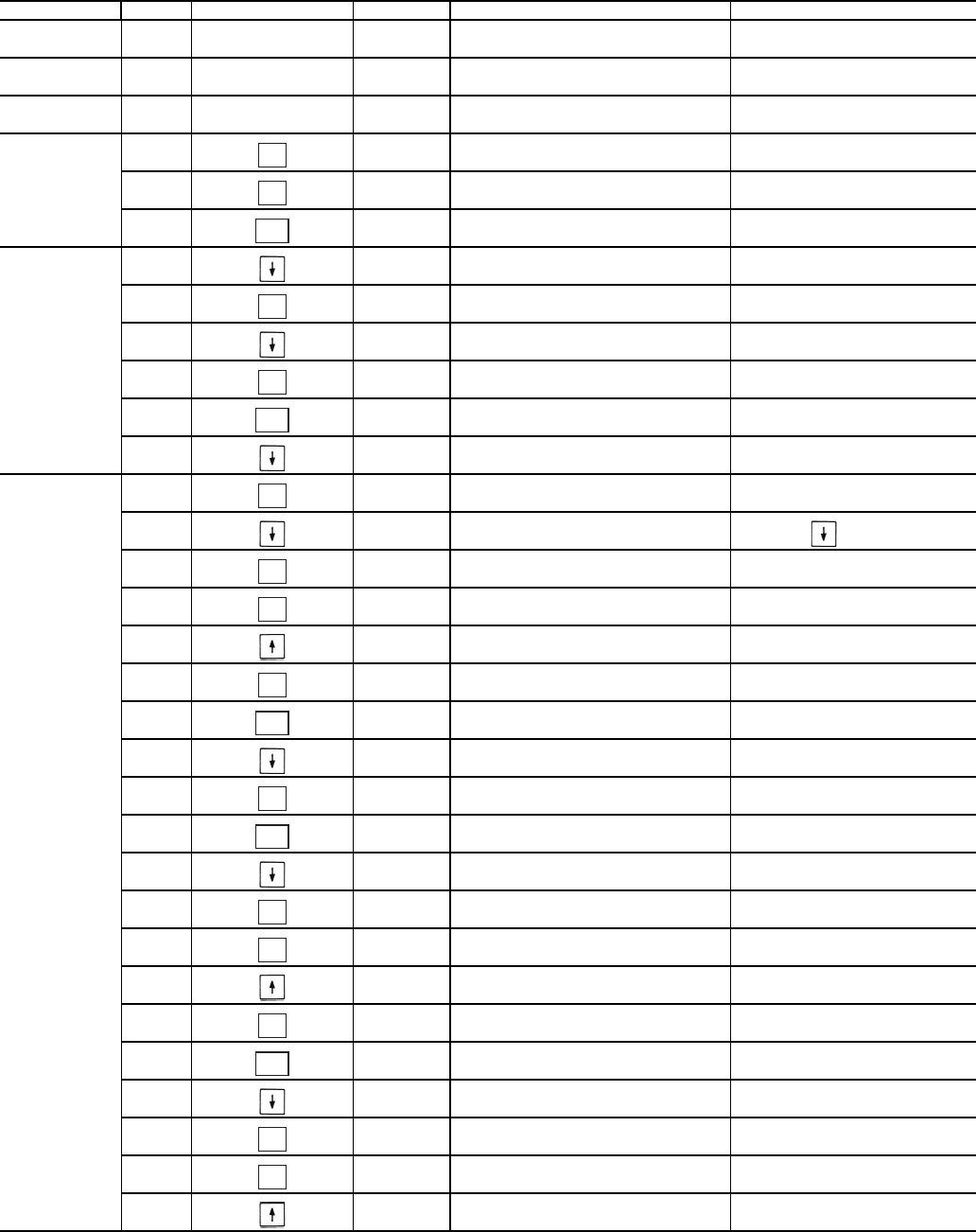
26
Table 21 — Dual Chiller Configuration (Master Chiller Example)
SUB-MODE ITEM KEYPAD ENTRY DISPLAY ITEM EXPANSION COMMENTS
DISP
UNIT
OPT1
OPT2
CTRL CONTROL METHOD
CTRL 0 SWITCH DEFAULT 0
OPT2
CCN
CCN
CCNA 1 CCN ADDRESS DEFAULT 1
CCNB
CCNB 0 CCN BUS NUMBER DEFAULT 0
CCN
RSET PROCEED TO
SUBMODE RESET
RSET CRST COOLING RESET TYPE
LLEN LEAD/LAG CHILLER ENABLE 15 ITEMS
LLEN DSBL SCROLLING STOPS
DSBL VALUE FLASHES
ENBL SELECT ENBL
LLEN ENBL LEAD/LAG CHILLER ENABLE CHANGE ACCEPTED
LLEN
MSSL MASTER /SLAVE SELECT
MSSL MAST MASTER /SLAVE SELECT DEFAULT MAST
MSSL
SLVA SLAVE ADDRESS
SLVA 0 SCROLLING STOPS
0 VALUE FLASHES
2 SELECT 2
SLVA 2 SLAVE ADDRESS CHANGE ACCEPTED
SLVA
LLBL LEAD/LAG BALANCE SELECT
LLBL 0 SCROLLING STOPS
0 VALUE FLASHES
2 SELECT 2 - Automatic
ENTER
ENTER
ESCAPE
ENTER
ENTER
ESCAPE
ENTER
ENTER
ENTER
ENTER
ESCAPE
ENTER
ESCAPE
ENTER
ENTER
ENTER
ESCAPE
ENTER
ENTER
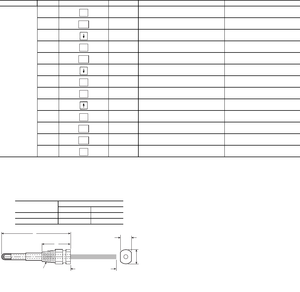
27
Table 21 — Dual Chiller Configuration (Master Chiller Example) (cont)
NOTES:
1. Master Control Method (CTRL) can be configured as 0-Switch, 2-Occupancy or 3-CCN.
2. Parallel Configuration (PARA) cannot be changed.
Temperature Reset — The control system is capable of
handling leaving-fluid temperature reset based on return cooler
fluid temperature. Because the change in temperature through
the cooler is a measure of the building load, the return tempera-
ture reset is in effect an average building load reset method.
The control system is also capable of temperature reset based
on outdoor-air temperature (OAT), space temperature (SPT), or
from an externally powered 4 to 20 mA signal. Accessory sen-
sors must be used for SPT reset (33ZCT55SPT) and for OAT
reset (HH79NZ014). The energy management module (EMM)
must be used for temperature reset using a 4 to 20 mA signal.
See Tables 23 and 24.
SUB-MODE ITEM KEYPAD ENTRY DISPLAY ITEM EXPANSION COMMENTS
RSET LLBL 2 LEAD/LAG BALANCE SELECT CHANGE ACCEPTED
LLBL
LLBD LEAD/LAG BALANCE DELTA
LLBD 168 LEAD/LAG BALANCE DELTA DEFAULT 168
LLBD
LLDY LAG START DELAY
LLDY 5 SCROLLING STOPS
5 VALUE FLASHES
10 SELECT 10
LLDY 10 LAG START DELAY CHANGE ACCEPTED
LLDY
RSET
PARA YES MASTER COMPLETE
ENTER
ESCAPE
ENTER
ESCAPE
ENTER
ENTER
ENTER
ESCAPE
ESCAPE
ENTER
A
B
1/4 N.P.T.
0.505/0.495
0.61
DIA
6” MINIMUM
CLEARANCE FOR
THERMISTOR
REMOVAL
Fig. 14 — Dual Leaving Water Thermistor Well
PART
NUMBER
DIMENSIONS in. (mm)
A B
10HB50106801 3.10 (78.7) 1.55 (39.4)
10HB50106802 4.10 (104.1) 1.28 (32.5)
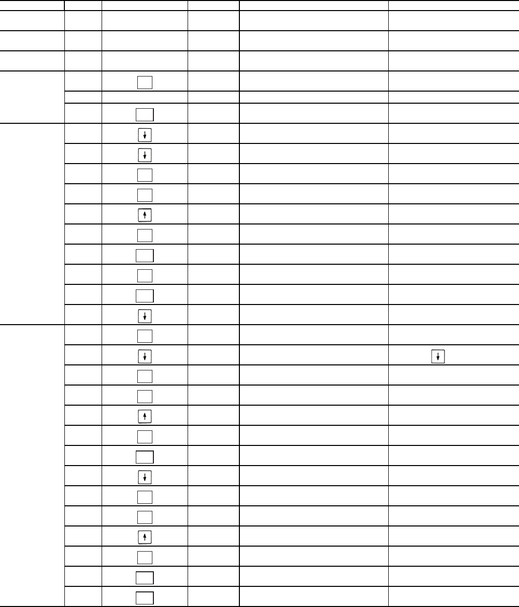
28
Table 22 — Dual Chiller Configuration (Slave Chiller Example)
NOTES:
1. Slave Control Method (CTRL) must be configured for 0.
2. Slave CCN Address (CCNA) must be different than Master.
3. Slave CCN Bus Number (CCNB) must be the same as Master
4. Slave does not require SLVA, LLBL, LLBD, or LLDY to be configured.
SUB-MODE ITEM KEYPAD ENTRY DISPLAY ITEM EXPANSION COMMENTS
DISP
UNIT
OPT1
OPT2
CTRL CONTROL METHOD
CTRL 0 SWITCH DEFAULT 0
OPT2
CCN
CCN
CCNA
CCNA 1 CCN ADDRESS SCROLLING STOPS
1 VALUE FLASHES
2SELECT 2
(SEE NOTE 2)
CCNA 2 CCN ADDRESS CHANGE ACCEPTED
CCN
CCNB 0 CCN BUS NUMBER DEFAULT 0
(SEE NOTE 3)
CCN
RSET PROCEED TO
SUBMODE RSET
RSET CRST COOLING RESET TYPE
LLEN LEAD/LAG CHILLER ENABLE 15 ITEMS
LLEN DSBL SCROLLING STOPS
DSBL VALUE FLASHES
ENBL SELECT ENBL
LLEN ENBL LEAD/LAG CHILLER ENABLE CHANGE ACCEPTED
LLEN
MSSL MASTER /SLAVE SELECT
MSSL MAST SCROLLING STOPS
MAST VALUE FLASHES
SLVE SELECT SLVE
MSSL SLVE MASTER /SLAVE SELECT CHANGE ACCEPTED
MSSL
RSET SLAVE COMPLETE
ENTER
ESCAPE
ENTER
ENTER
ENTER
ESCAPE
ENTER
ESCAPE
ENTER
ENTER
ENTER
ENTER
ESCAPE
ENTER
ENTER
ENTER
ESCAPE
ESCAPE
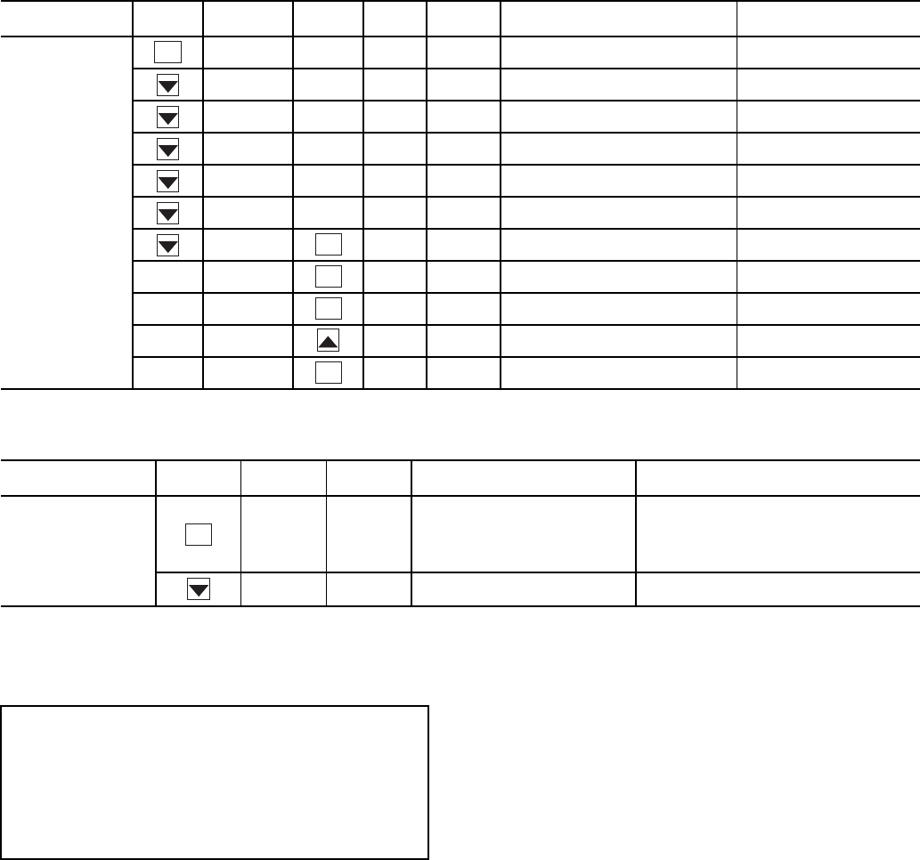
29
Table 23 — Menu Configuration of 4 to 20 mA Cooling Set Point Control
Table 24 — 4 to 20 mA Reset
NOTE: The example above shows how to configure the chiller for
4 to 20 mA reset. No reset will occur at 4.0 mA input, and a 5.0 F
reset will occur at 20.0 mA. An EMM (energy management module)
is required.
To use outdoor air or space temperature reset, four variables
must be configured. In the Configuration mode under the sub-
mode RSET, items (Configuration
RSET
CRST),
(Configuration
RSET
RM.NO), (Configuration
RSET
RM.F), and (Configuration
RSET
RT.DG)
must be properly set. See Table 25 — Configuring Outdoor Air
and Space Temperature Reset. The outdoor air reset example
provides 0° F (0° C) chilled water set point reset at 85.0 F
(29.4 C) outdoor-air temperature and 15.0 F (8.3 C) reset at
55.0 F (12.8 C) outdoor-air temperature. The space tempera-
ture reset example provides 0° F (0° C) chilled water set point
reset at 72.0 F (22.2 C) space temperature and 6.0 F (3.3 C) re-
set at 68.0 F (20.0 C) space temperature. The variable CRST
should be configured for the type of reset desired. The variable
RM.NO should be set to the temperature that no reset should
occur. The variable RM.F should be set to the temperature that
maximum reset is to occur. The variable RM.DG should be set
to the maximum amount of reset desired. Figures 15 and 16 are
examples of outdoor air and space temperature resets.
To use return reset, four variables must be configured. In the
Configuration mode under the sub-mode RSET, items CRST,
RT.NO, RT.F and RT.DG must be properly set. See Table 26
— Configuring Return Temperature Reset. This example pro-
vides 5.0 F (2.8 C) chilled water set point reset at 2.0 F (1.1 C)
cooler T and 0° F (0° C) reset at 10.0 F (5.6 C) cooler T. The
variable RT.NO should be set to the cooler temperature differ-
ence (T) where no chilled water temperature reset should oc-
cur. The variable RT.F should be set to the cooler temperature
difference where the maximum chilled water temperature reset
should occur. The variable RM.DG should be set to the maxi-
mum amount of reset desired.
To verify that reset is functioning correctly proceed to Run
Status mode, sub-mode VIEW, and subtract the active set point
(Run Status
VIEW
SETP) from the control point (Run
Status
VIEW
CTPT) to determine the degrees reset.
MODE
(RED LED)
KEYPAD
ENTRY SUB-MODE KEYPAD
ENTRY ITEM DISPLAY ITEM
EXPANSION COMMENT
CONFIGURATION
DISP
UNIT
OPT1
OPT2
CCN
RSET
SLCT CLSP 0 COOLING SETPOINT SELECT
0 Scrolling Stops
0 Flashing ‘0’
3Select ‘3’
3 Change Accepted
SUB-MODE KEYPAD
ENTRY ITEM DISPLAY ITEM
EXPANSION COMMENT
RSET
CRST 1 COOLING RESET
TYPE
0 = no reset
1 = 4 to 20 mA input
2 = Outdoor air temp
3 = Return Fluid
4 = Space Temperature
MA.DG 5.0 F
(2.8 C)
DEGREES COOL
RESET
Default: 0° F (0° C) Reset at 20 mA
Range: –30 to 30 F (–16.7 to 16.7 C)
ENTER
ENTER
ENTER
ENTER
ENTER
ENTER
IMPORTANT: Care should be taken when interfacing with
other control systems due to possible power supply differ-
ences: full wave bridge versus half wave rectification. Con-
nection of control devices with different power supplies
may result in permanent damage. ComfortLink™ controls
incorporate power supplies with half wave rectification. A
signal isolation device should be utilized if the signal gen-
erator incorporates a full wave bridge rectifier.
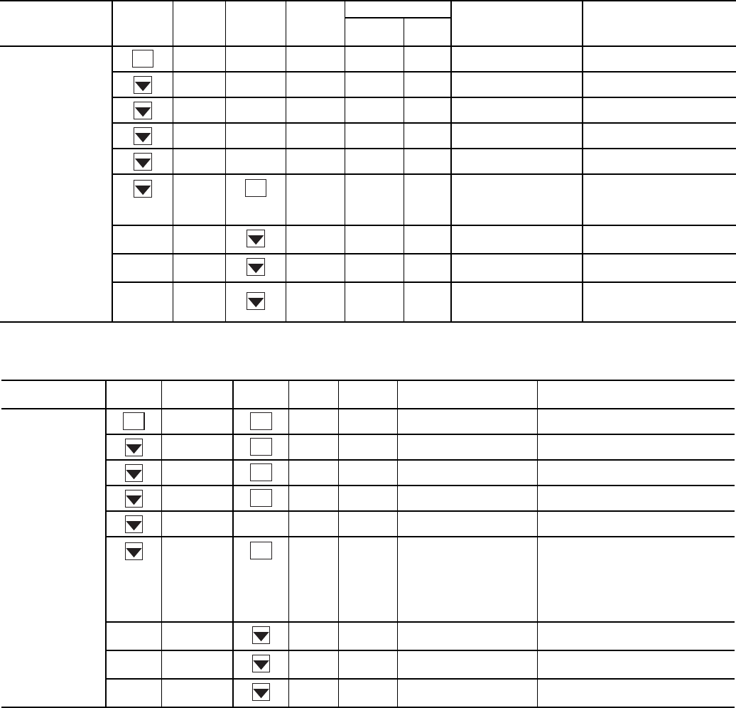
30
Table 25 — Configuring Outdoor Air and Space Temperature Reset
*1 item skipped in this example.
Table 26 — Configuring Return Temperature Reset
*1 item skipped in this example.
MODE
(RED LED)
KEYPAD
ENTRY
SUB-
MODE
KEYPAD
ENTRY ITEM
DISPLAY ITEM
EXPANSION COMMENT
Outdoor
Air Space
CONFIGURATION
DISP
UNIT
OPT1
OPT2
CCN
RSET CRST 2 4 COOLING RESET
TYPE
2 = Outdoor-Air Temperature
(Connect to LVT-4,5)
4 = Space Temperature
(Connect to LVT-3,4)
RM.NO* 85 °F 72 °F REMOTE - NO
RESET TEMP
Default: 125.0 F (51.7 C)
Range: 0° to125 F
RM.F 55 °F 68 °F REMOTE - FULL
RESET TEMP
Default: 0.0° F (-17.7 C)
Range: 0° to 125 F
RM.DG 15 °F 6 °F REMOTE - DEGREES
RESET
Default: 0° F (0° C)
Range: –30 to 30 F
(–34.4 to -1.1 °C)
MODE
(RED LED)
KEYPAD
ENTRY SUB-MODE KEYPAD
ENTRY ITEM DISPLAY ITEM
EXPANSION COMMENT
CONFIGURATION
DISP TEST ON/OFF TEST DISPLAY LEDs
UNIT TYPE X UNIT TYPE
OPT1 FLUD X COOLER FLUID
OPT2 CTRL X CONTROL METHOD
CCN
RSET CRST 3 COOLING RESET TYPE
0 = No Reset
1 = 4 to 20 mA Input (EMM required)
(Connect to EMM TB6-2,3)
2 = Outdoor-Air Temperature
3 = Return Fluid
4 = Space Temperature
(Connect to TB5-5,6)
RT.NO* 10.0 FRETURN FLUID - NO
RESET TEMP
Default: 10.0 F (5.6 C)
Range: 0° to10 F COOLER T
RT.F 2.0 FRETURN FLUID - FULL
RESET TEMP
Default: 0 F (–17.8 C)
Range: 0° to 30 F COOLER T
RT.DG 5.0 FRETURN - DEGREES
RESET
Default: 0 F (0 C)
Range: –30 to 30°F (–16.7 to 16.7 C)
ENTER
ENTER
ENTER
ENTER
ENTER
ENTER
ENTER
ENTER
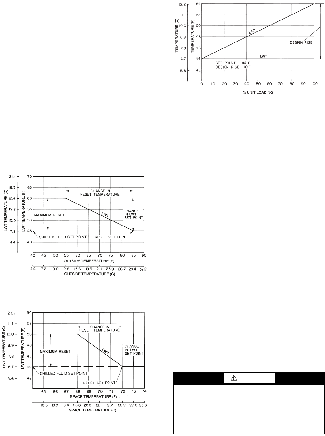
31
Under normal operation, the chiller will maintain a constant
leaving fluid temperature approximately equal to the chilled
fluid set point. As the cooler load varies, the entering cooler
fluid will change in proportion to the load as shown in Fig. 17.
Usually the chiller size and leaving-fluid temperature set point
are selected based on a full-load condition. At part load, the flu-
id temperature set point may be colder than required. If the
leaving fluid temperature was allowed to increase at part load,
the efficiency of the machine would increase.
Return temperature reset allows for the leaving temperature
set point to be reset upward as a function of the return fluid
temperature or, in effect, the building load.
Demand Limit — Demand limit is a feature that allows
the unit capacity to be limited during periods of peak energy us-
age. There are 3 types of demand limiting that can be config-
ured. The first type is through 2-stage switch control, which will
reduce the maximum capacity to 2 user-configurable percentag-
es. The second type is by 4 to 20 mA signal input which will re-
duce the maximum capacity linearly between 100% at a 4 mA
input signal (no reduction) down to the user-configurable level
at a 20 mA input signal. The third type uses the CCN Loadshed
module and has the ability to limit the current operating capaci-
ty to maximum and further reduce the capacity if required.
NOTE: The 2-stage switch control and 4 to 20-mA input sig-
nal types of demand limiting require the energy management
module (EMM).
To use demand limit, select the type of demand limiting to
use. Then configure the demand limit set points based on the
type selected.
DEMAND LIMIT (2-Stage Switch Controlled) — To con-
figure demand limit for 2-stage switch control set the Demand
Limit Select (Configuration
RSET
DMDC) to 1. Then
configure the 2 Demand Limit Switch points (Configura-
tion
RSET
DLS1) and (Configuration
RSET
DLS2)
to the desired capacity limit. See Table 27. Capacity steps are
controlled by 2 relay switch inputs field wired to LVT as shown
in Fig. 5.
For demand limit by 2-stage switch control, closing the first
stage demand limit contact will put the unit on the first demand
limit level. The unit will not exceed the percentage of capacity
entered as Demand Limit Switch 1 set point (DLS1). Closing
contacts on the second demand limit switch prevents the unit
from exceeding the capacity entered as Demand Limit Switch
2 set point. The demand limit stage that is set to the lowest de-
mand takes priority if both demand limit inputs are closed. If
the demand limit percentage does not match unit staging, the
unit will limit capacity to the closest capacity stage.
To disable demand limit configure DMDC to 0. See
Table 27.
EXTERNALLY POWERED DEMAND LIMIT (4 to
20 mA Controlled) — To configure demand limit for 4 to 20
mA control set the Demand Limit Select (Configura-
tion
RSET
DMDC) to 2. Then configure the Demand
Limit at 20 mA (Configuration
RSET
DM20) to the
maximum loadshed value desired. Connect the output from an
externally powered 4 to 20 mA signal to terminal block LVT,
terminals 7 and 8 (+,–). Refer to the unit wiring diagram for
these connections to the optional/accessory energy manage-
ment module and terminal block. The control will reduce al-
lowable capacity to this level for the 20 mA signal. See Table
27 and Fig. 18.
LEGEND
LWT — Leaving Water (Fluid) Temperature
Fig. 15 — Outdoor-Air Temperature Reset
LEGEND
LWT — Leaving Water (Fluid) Temperature
Fig. 16 — Space Temperature Reset
CAUTION
Care should be taken when interfacing with other manufac-
turer’s control systems, due to possible power supply
differences, full wave bridge versus half wave rectification.
The two different power supplies cannot be mixed.
ComfortLink™ controls use half wave rectification. A sig-
nal isolation device should be utilized if a full wave bridge
signal generating device is used.
LWT
LWT
LEGEND
Fig. 17 — Standard Chilled Fluid
Temperature Control — No Reset
EWT — Entering Water (Fluid) Temperature
LWT — Leaving Water (Fluid) Temperature
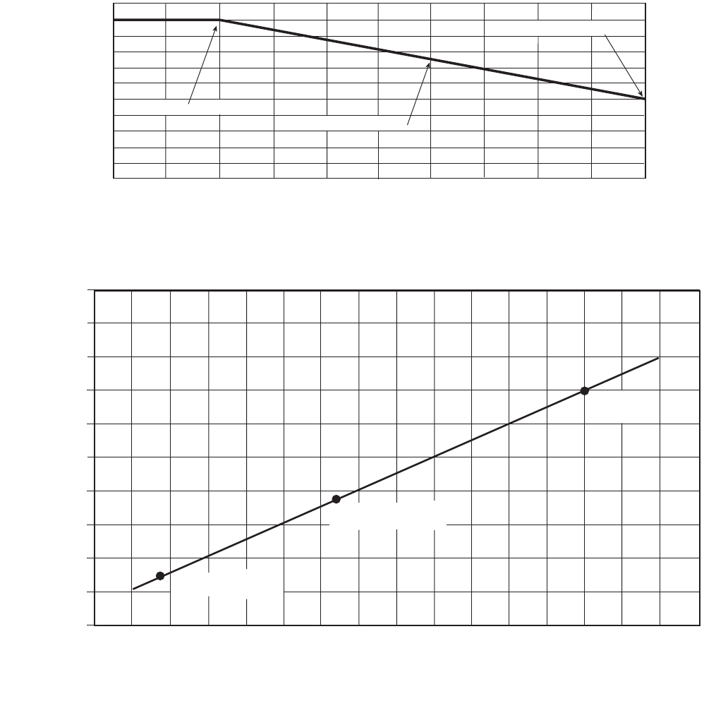
32
DEMAND LIMIT (CCN Loadshed Controlled) — To con-
figure Demand Limit for CCN Loadshed control set the De-
mand Limit Select (Configuration
RSET
DMDC) to 3.
Then configure the Loadshed Group Number (Configura-
tion
RSET
SHNM), Loadshed Demand Delta (Configu-
ration
RSET
SHDL), and Maximum Loadshed Time
(Configuration
RSET
SHTM). See Table 27.
The Loadshed Group number is established by the CCN
system designer. The ComfortLink™ controls will respond to a
Redline command from the Loadshed control. When the
Redline command is received, the current stage of capacity is
set to the maximum stages available. Should the loadshed con-
trol send a Loadshed command, the ComfortLink controls will
reduce the current stages by the value entered for Loadshed
Demand delta. The Maximum Loadshed Time is the maximum
length of time that a loadshed condition is allowed to exist. The
control will disable the Redline/Loadshed command if no
Cancel command has been received within the configured
maximum loadshed time limit.
Cooling Set Point (4 to 20 mA) — A field supplied
and generated, externally powered 4 to 20 mA signal can be
used to provide the leaving fluid temperature set point. Connect
the signal to LVT-10,8 (+,–). See Table 27 for instructions to
enable the function. Figure 19 shows how the 4 to 20 mA sig-
nal is linearly calculated on an overall 10 F to 80 F range for
fluid types (Configuration
OPT1
FLUD) 1 or 2. The set
point will be limited by the fluid (FLUD) type. Be sure that the
chilled water loop is protected at the lowest temperature.
50% CAPACITY AT 20 mA
75% CAPACITY AT 12 mA
100% CAPACITY AT 4 mA
0 2 4 6810 12 14 16 18 20
DEMAND LIMIT SIGNAL – 4 - 20 mA INPUT
100
80
60
40
20
0
MAX. ALLOWABLE LOAD (%)
Fig. 18 — 4 to 20-mA Demand Limiting
100
(38)
80
(27)
60
(15)
40
(4.4)
20
(-7)
0
(-17)
4 6.3 8.6 10.9 13.1 15.4 17.7 20
4 TO 20 mA SIGNAL TO EMM
SET POINT, F (C)
90
(32)
70
(21)
50
(10)
30
(-1)
10
(-12)
(FLUD = 2) MINIMUM
SET POINT 14 F (-10 C)
(FLUD = 1) MINIMUM
SET POINT 38 F (3.3 C)
MAXIMUM
SET POINT
70 F (21.1 C)
Fig. 19 — Cooling Set Point (4 to 20 mA)
EMM — Energy Management Module
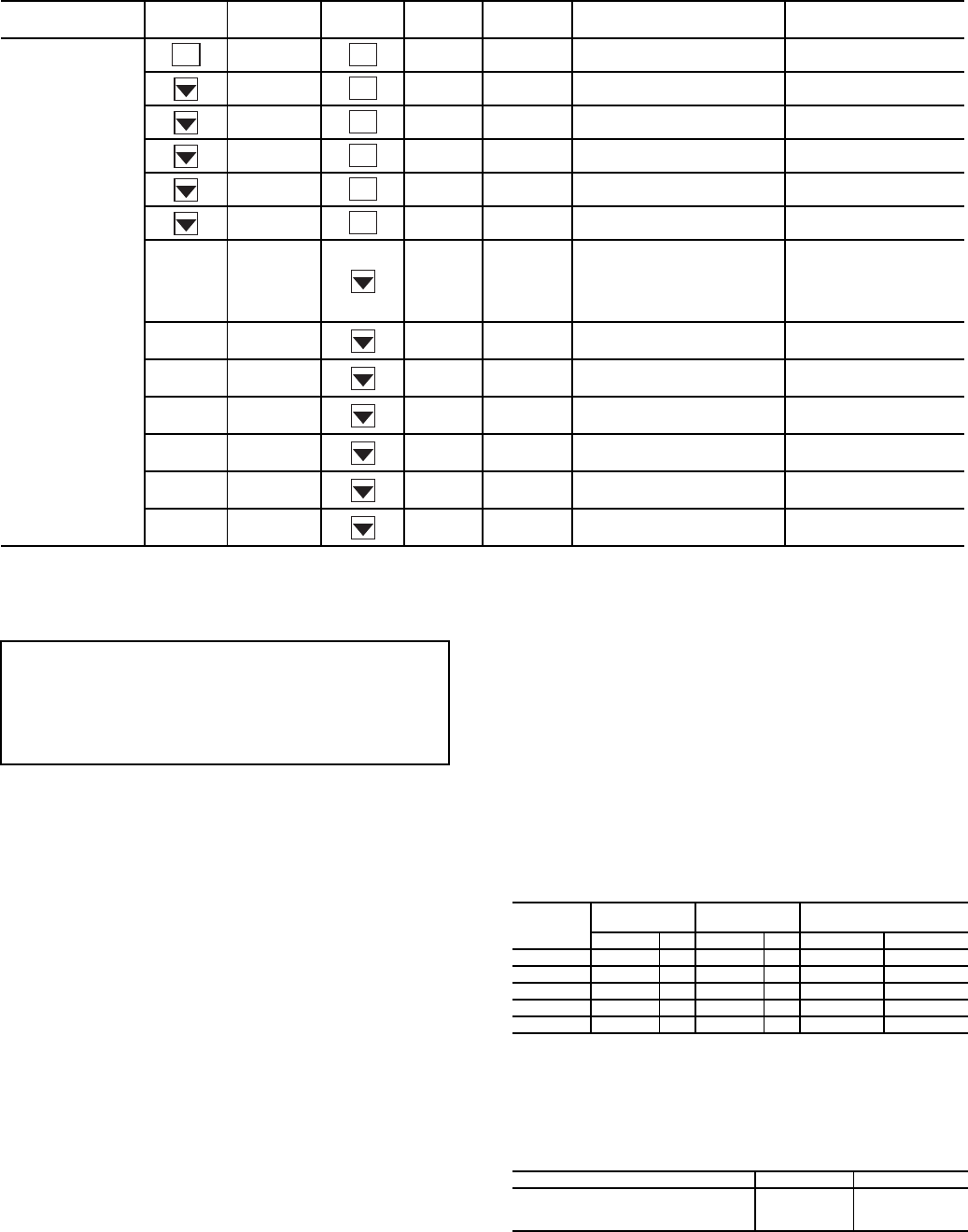
33
Table 27 — Configuring Demand Limit
*Seven items skipped in this example.
PRE-START-UP
Do not attempt to start the chiller until following checks
have been completed.
System Check
1. Check all auxiliary components, such as chilled fluid
pumps, air-handling equipment, condenser pump or other
equipment to which the chiller supplies liquid. Consult
manufacturer's instructions. Verify that any pump inter-
lock contacts have been properly installed. If the unit has
field-installed accessories, be sure all are properly in-
stalled and wired correctly. Refer to unit wiring diagrams.
2. Use the scrolling marquee display to adjust the Cooling
Set Point.
3. Fill chilled fluid circuit with clean water (with recom-
mended inhibitor added) or other non-corrosive fluid to
be cooled. Bleed all air out of the high points of the sys-
tem. If chilled water is to be maintained at a temperature
below 40 F (4.4 C), a brine of sufficient concentration
must be used to prevent freeze-up at anticipated suction
temperatures. To ensure sufficient loop volume, see
Table 28.
4. Check tightness of all electrical connections.
5. Oil should be visible in the compressor sightglass(es).
See Fig. 20. An acceptable oil level in the compressors is
from 1/8 to 3/8 of sight glass when the compressors are off.
Adjust the oil level as required. See Oil Charge section on
page 37 for Carrier approved oils.
6. Crankcase heaters must be firmly attached to compres-
sors, and must be on for 24 hours prior to start-up
(30MPA units only).
7. Electrical power source must agree with unit nameplate.
8. Check rotation of scroll compressors. Monitor control
alarms during first compressor start up for reverse rota-
tion protection alarm.
Table 28 — Minimum Flow Rates and Minimum
Loop Volume (for Comfort Cooling)
LEGEND
NOTES:
Gallons = V x AHRI capacity in tons.
Liters = N x AHRI capacity in kW.
MODE KEYPAD
ENTRY SUB-MODE KEYPAD
ENTRY ITEM DISPLAY ITEM EXPANSION COMMENT
CONFIGURATION DISP TEST ON/OFF Test Display LEDs
UNIT TYPE X Unit Type
OPT1 FLUD X Cooler Fluid
OPT2 CTRL X Control Method
CCN CCNA X CCN Address
RSET CRST X Cooling Reset Type
DMDC* X Demand Limit Select
Default: 0
0 = None
1 = Switch
2 = 4 to 20 mA Input
3 = CCN Loadshed
DM20 XXX % Demand Limit at 20 mA Default: 100%
Range: 0 to 100
SHNM XXX Loadshed Group
Number
Default: 0
Range: 0 to 99
SHDL XXX% Loadshed Demand
Delta
Default: 0%
Range: 0 to 60%
SHTM XXX MIN Maximum Loadshed
Time
Default: 60 min.
Range: 0 to 120 min.
DLS1 XXX % Demand Limit
Switch 1
Default: 80%
Range: 0 to 100%
DLS2 XXX % Demand Limit
Switch 2
Default: 50%
Range: 0 to 100%
ENTER
ENTER
ENTER
ENTER
ENTER
ENTER
ENTER
IMPORTANT: Before beginning Pre-Start-Up or Start-Up,
complete Start-Up Checklist for 30MP Liquid Chiller at
end of this publication (page CL-1 to CL-8). The checklist
assures proper start-up of a unit, and provides a record of
unit condition, application requirements, system informa-
tion, and operation at initial start-up.
UNIT SIZE EVAPORATOR CONDENSER* MINIMUM EVAPORATOR
LOOP VOLUME
Gal./Min L/s Gal./Min L/s Gal. L
30MP015 22 1.4 22 1.4 46.2 174.9
30MP020 28 1.8 28 1.8 60.9 230.5
30MP030 43 2.7 43 2.7 92.4 349.7
30MP040 55 3.5 55 3.5 78.4 296.7
30MP045 64 4.0 64 4.0 91.6 346.7
AHRI — Air Conditioning, Heating, and Refrigeration Institute
N—Liters per kW
V—Gallons per ton
APPLICATION V N
Normal Air Conditioning 33.25
Process Type Cooling 6 to 10 6.5 to 10.8
Low Ambient Operation 6 to 10 6.5 to 10.8
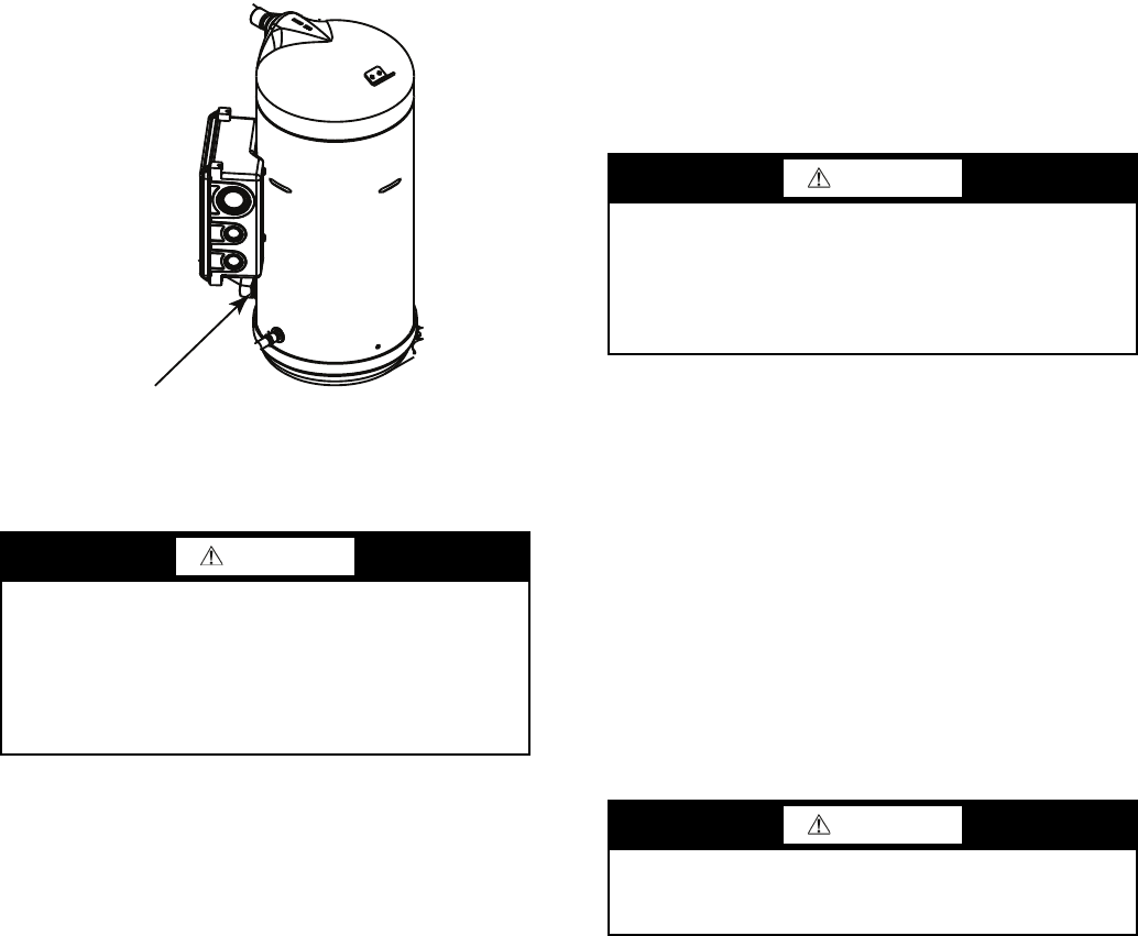
34
START-UP AND OPERATION
Compressor crankcase heaters must be on for 24 hours be-
fore start-up. To energize the crankcase heaters, close the field
disconnect. Leave the compressor circuit breakers off/open.
The crankcase heaters are now energized.
NOTE: Refer to Start-Up Checklist on pages CL-1 to CL-8.
Actual Start-Up — Actual start-up should be done only
under supervision of a qualified refrigeration mechanic.
1. Be sure all service valves are open (30MPA units only).
2. Using the scrolling marquee display, set leaving-fluid set
point (Set Points
COOL
CSP.1). No cooling range
adjustment is necessary.
3. Start chilled fluid pump (if not configured for cooler
pump control).
4. Turn ENABLE/OFF/REMOTE CONTACT switch to
ENABLE position.
5. Allow unit to operate and confirm that everything is func-
tioning properly. Check to see that leaving fluid tempera-
ture agrees with leaving set point (Set Points
COOL
CSP.1) or (Set Points
COOL
CSP.2), or if reset is
used, with the control point (Run Status
VIEW
CTPT).
6. Check the cooler leaving chilled water temperature to see
that it remains well above 32 F (0° C), or the brine freez-
ing point if the unit is a medium temperature brine unit.
7. Recheck compressor oil level (see Oil Charge section).
Check Refrigerant Charge — All 30MPW units are
shipped with a complete operating charge of R-410A and
should be under sufficient pressure to conduct a leak test after
installation. If there is no system pressure, admit nitrogen until
a pressure is observed and then proceed to test for leaks. After
leaks are repaired, the system must be dehydrated.
All refrigerant charging should be done through the ¼-in.
Schraeder connection on the liquid line. Do NOT add refriger-
ant charge through the low-pressure side of the system. If com-
plete charging is required, weigh in the appropriate charge for
the circuit as shown on the unit nameplate. If partial charging is
required, operate circuit at full load and add charge until the
sight glass is clear of bubbles.
The 30MPA units (condenserless) are shipped with a nitro-
gen holding charge only. After chiller assembly is completed in
the field, system must be fully charged. While the unit is run-
ning at full capacity, add refrigerant until the sight glass is clear.
R-410A is the normal refrigerant.
Do not open the liquid valve until there is a charge in re-
mainder of system. A positive pressure indicates a charge in
system. With the unit operating at full load, check liquid line
sight glass to be sure the unit is fully charged (bubbles in the
sight glass indicate the unit is not fully charged).
If there is no refrigerant vapor pressure in the system, the
entire system must be leak tested. After repairing leaks, evacu-
ate the system before recharging.
Follow approved evacuation procedures when removing
refrigeration. Release remaining pressure to an approved evac-
uated cylinder.
The liquid charging method is recommended for complete
charging or when additional charge is required.
EVACUATION AND DEHYDRATION — Because the
30MP systems use polyolester (POE) oil, which can absorb
moisture, it is important to minimize the amount of time that
the system interior is left exposed to the atmosphere. Minimiz-
ing the exposure time of the oil to the atmosphere will mini-
mize the amount of moisture that needs to be removed during
evacuation.
Once all of the piping connections are complete, leak test
the unit and then pull a deep dehydration vacuum. Connect the
vacuum pump to the high flow Schraeder valve in the suction
line and liquid line. For best results, it is recommended that a
vacuum of at least 500 microns (0.5 mm Hg) be obtained. Af-
terwards, to ensure that no moisture is present in the system,
perform a standing vacuum-rise test.
With the unit in deep vacuum (500 microns or less), isolate
the vacuum pump from the system. Observe the rate-of-rise of
the vacuum in the system. If the vacuum rises by more than
50 microns in a 30-minute time period, then continue the dehy-
dration process. Maintain a vacuum on the system until the
standing vacuum requirement is met. This will ensure a dry
system.
By following these evacuation and dehydration procedures,
the amount of moisture present in the system will be mini-
mized. It is required that liquid line filter driers be installed
between the condenser(s) and the expansion devices to capture
any foreign debris and provide additional moisture removal
capacity.
CAUTION
Crankcase heaters on 30MPA units are wired into the con-
trol circuit, so they are always operable as long as the main
power supply disconnect is on (closed), even if any safety
device is open. Compressor heaters must be on for 24
hours prior to the start-up of any compressor. Equipment
damage could result if heaters are not energized for at least
24 hours prior to compressor start-up.
OIL SIGHTGLASS
Fig. 20 — Sight Glass Location
a30-4978
CAUTION
Never charge liquid into low-pressure side of system. Do
not overcharge. Overcharging results in higher discharge
pressure, possible compressor damage, and higher power
consumption. During charging or removal of refrigerant, be
sure water is continuously circulating through the cooler to
prevent freezing.
CAUTION
Be careful not to overcharge the system. Overcharging
results in higher discharge pressure, possible compressor
damage, and higher power consumption.
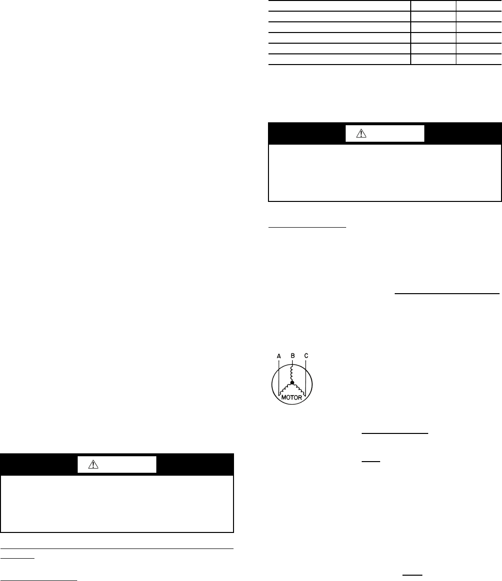
35
LIQUID CHARGING METHOD — Add charge to the unit
through the liquid line service valve. Never charge liquid into
the low-pressure side of the system.
1. Close liquid line ball valve (30MPA only).
2. Connect a refrigerant cylinder loosely to the high flow
Schraeder valve connection on the liquid line. Purge the
charging hose and tighten the connections.
3. Open the refrigerant cylinder valve.
4. If the system has been dehydrated and is under vacuum,
break the vacuum with refrigerant gas. For R-410A, build
up system pressure to 101 psig and 32 F (697 kPa and
0° C). Invert the refrigerant cylinder so that the liquid re-
frigerant will be charged.
5. a. For complete charge of 30MPW units, follow
charging by weight procedure. When charge is
nearly full, complete the process by observing the
sight glass for clear liquid flow while the unit is
operating. The use of sight glass charging is valid
only when unit is operating at full capacity.
b. For complete charge of 30MPA units or where
refrigerant cylinder cannot be weighed, follow the
condenser manufacturer’s charging procedure or
follow charging by sight glass procedure. The use
of sight glass charging is valid only when unit is
operating at full capacity.
6. a. The 30MPA condenserless units are shipped
with a nitrogen holding charge. After installation
with the field-supplied system high side, the com-
plete system should be evacuated and charged per
the condenser manufacturer’s charging procedure
or charged until the sight glass is clear (with the
unit running at full capacity). To achieve maxi-
mum system capacity, add additional charge equal
to the difference between the condenser optimal
charge and the condenser minimum charge, which
can be obtained from the charge data provided in
the condenser installation instructions.
b. To ensure maximum performance of 30MPW
units, raise the compressor saturated discharge
temperature (SDT) to approximately 100 F
(37.8 C) by throttling the condenser water intake.
Add charge until there is approximately 9 to 12° F
(5.0 to 6.6° C) of system subcooling (SDT minus
actual temperature entering the thermostatic
expansion valve).
Operating Limitations
TEMPERATURES (See Table 29 for 30MP standard tem-
perature limits).
High Cooler Leaving Chilled Water (Fluid) Temperatures
(LCWT) — During start-up with cooler the LCWT should not
be above approximately 60 F (16 C).
Low Cooler LCWT — For standard units with fresh water,
the LCWT must be no lower than 40 F (4.4 C). For standard
units with a proper brine solution, the LCWT must be no lower
than 32 F (0° C). If the unit is the factory-installed optional
medium temperature brine unit, the cooler LCWT can go
down to 15 F (–9.4 C).
Table 29 — Temperature Limits for
Standard 30MP Units
LEGEND
*For sustained operation, EWT should not exceed 85 F (29.4 C).
†Unit requires modification below this temperature.
VOLTAGE — ALL UNITS
Main Power Supply — Minimum and maximum acceptable
supply voltages are listed in the Installation Instructions.
Unbalanced 3-Phase Supply Voltage — Never operate a motor
where a phase imbalance between phases is greater than 2%.
To determine percent voltage imbalance:
The maximum voltage deviation is the largest difference
between a voltage measurement across 2 legs and the average
across all 3 legs.
Example: Supply voltage is 240-3-60.
AB = 243 v
BC = 236 v
AC = 238 v
1. Determine average voltage:
2. Determine maximum deviation from average voltage:
(AB) 243 – 239 = 4 v
(BC) 239 – 236 = 3 v
(AC) 239 – 238 = 1 v
Maximum deviation is 4 v.
3. Determine percent voltage imbalance:
CAUTION
Do not operate with cooler leaving chiller water (fluid)
temperature (LCWT) below 32 F (0° C) for standard units
with proper brine solution or 40 F (4.4 C) for the standard
units with fresh water, or below 15 F (–9.4 C) for units fac-
tory built for medium temperature brine.
TEMPERATURE LIMIT F C
Maximum Condenser LWT 140 60
Minimum Condenser EWT 70 21
Maximum Cooler EWT* 95 35
Maximum Cooler LWT 70 21
Minimum Cooler LWT† 40 4
EWT — Entering Fluid (Water) Temperature
LWT — Leaving Fluid (Water) Temperature
CAUTION
Medium temperature brine duty application (below 32 F
[0° C] LCWT) for chiller normally requires factory modifi-
cation. Contact your Carrier representative for applicable
LCWT range for standard water-cooled chiller in a specific
application.
% Voltage Imbalance = 100 x
max voltage deviation
from avg voltage
average voltage
Average voltage = 243 + 236 + 238
3
=717
3
= 239
% Voltage Imbalance = 100 x 4
239
= 1.7%
a30-4979
36
This voltage imbalance is satisfactory as it is below the
maximum allowable of 2%.
Control Circuit Power — Power for the control circuit is
supplied from the main incoming power through a factory-
installed control power transformer (TRAN1) for all models.
Field wiring connections are made to the LVT.
OPERATION SEQUENCE
The unit is started by putting the ENABLE/OFF/REMOTE
CONTACT switch in the ENABLE or REMOTE CONTACT
position. When the unit receives a call for cooling (either from
the internal control or CCN network command or remote con-
tact closure), the unit stages up in capacity to maintain the leav-
ing fluid set point. The first compressor starts 11/2 to 3 minutes
after the call for cooling.
For all units, if temperature reset is being used, the unit con-
trols to a higher leaving-fluid temperature as the building load
reduces. If demand limit is used, the unit may temporarily be
unable to maintain the desired leaving-fluid temperature be-
cause of imposed power limitations.
SERVICE
Electronic Components
CONTROL COMPONENTS — Unit uses an advanced elec-
tronic control system that normally does not require service.
For details on controls refer to Operating Data section.
Access to the controls is through a hinged panel. Inner pan-
els are secured in place and should not be removed unless all
power to the chiller is off.
Compressor Replacement — All models contain
scroll compressors and have two or three compressors. A com-
pressor is most easily removed from the side of the unit or
above, depending on where clearance space was allowed dur-
ing unit installation. See Fig. 21.
Remove the junction box cover bolts and disconnect the
compressor power and crankcase heater connections (30MPA
only). Remove the cable from the compressor junction box.
Remove the connections from the high-pressure switch. Re-
move the crankcase heater. Knock the same holes out of the
new compressor junction box and install the cable connectors
from the old compressor.
The compressors are bolted to rails, which are in turn bolted
to the unit basepan for all sizes. Remove the 4 bolts holding the
compressor to the rail on the basepan. Save the mounting hard-
ware for use with the new compressor. Carefully cut the com-
pressor suction and discharge lines with a tubing cutter as close
to the compressor as feasible. Remove high-pressure switch
and pressure transducer(s) if required for compressor removal.
Lift one corner of the compressor at a time and remove all the
steel spacers. Remove the old compressor from the unit.
Slide the new compressor in place on the rails. Lifting one
side of the compressor at a time, replace all of the compressor
mounting hardware. Using new tubing as required, reconnect
compressor suction and discharge lines. Using hardware saved,
reinstall the mounting bolts and washers through the compres-
sor feet. Using proper techniques, braze suction and discharge
lines and check for leaks. Reconnect oil equalization line.
Re-install the crankcase heater (30MPA units). Reconnect
the compressor power connections and high-pressure switch
wiring as on the old compressor. Refer to Fig. 21. Following
the installation of the new compressor, tighten all hardware to
the following specifications. (See Table 30.)
Table 30 — Unit Torque Specification
30MPW Condenser and 30MP Cooler
BRAZED-PLATE COOLER AND CONDENSER HEAT
EXCHANGER REPLACEMENT — Brazed-plate heat ex-
changers cannot be repaired if they develop a leak. If a leak
(refrigerant or water) develops, the heat exchanger must be
replaced. To replace a brazed plate heat exchanger:
1. Disconnect the liquid-in and liquid-out connections at the
heat exchanger.
2. Check that the replacement heat exchanger is the same as
the original heat exchanger. For the condensers, compare
part numbers on the heat exchangers. For the coolers, in-
sulation covers the manufacturer’s part number. Make
sure the depths of the replacement and original cooler
heat exchangers are the same.
3. Recover the refrigerant from the system, and unsolder the
refrigerant-in and refrigerant-out connections.
4. Remove the four nuts holding the heat exchanger to the
brackets. Save the nuts.
5. Install the replacement heat exchanger in the unit and at-
tach to the bracket using the four nuts removed in Step 4.
For sizes 015 and 020, torque is 7-10 ft-lb. For sizes 030-
045, torque is 35 to 50 ft-lb.
6. Carefully braze the refrigerant lines to the connections on
the heat exchanger. Lines should be soldered using silver
as the soldering material with a minimum of 45% silver.
Keep the temperature below 1472 F (800 C) under nor-
mal soldering conditions (no vacuum) to prevent the cop-
per solder of the brazed plate heat exchanger from chang-
ing its structure. Failure to do so can result in internal
or external leakage at the connections which cannot be
repaired.
7. For coolers, ensure that the original size tubing is used
(1/2-in. for sizes 015 and 020 and 5/8-in. for sizes 030-045)
between the TXV and the cooler. The TXV must be lo-
cated within 1 ft of the heat exchanger, with no bends be-
tween the TXV outlet and the cooler inlet.
8. Reconnect the water/brine lines.
9. Dehydrate and recharge the unit. Check for leaks.
BRAZED-PLATE COOLER AND CONDENSER HEAT
EXCHANGER CLEANING — Brazed-plate heat exchang-
ers must be cleaned chemically. A professional cleaning ser-
vice skilled in chemical cleaning should be used. Use a weak
acid (5% phosphoric acid, or if the heat exchanger is cleaned
frequently, 5% oxalic acid). Pump the cleaning solution
through the exchanger, preferably in a backflush mode. After
cleaning, rinse with large amounts of fresh water to dispose of
all the acid. Cleaning materials must be disposed of properly.
IMPORTANT: If the supply voltage phase imbalance is
more than 2%, contact your local electric utility company
immediately. Do not operate unit until imbalance condition
is corrected.
WARNING
Electrical shock can cause personal injury and death. Shut
off all power to this equipment during service. There may
be more than one disconnect switch. Tag all disconnect
locations to alert others not to restore power until work is
completed.
FASTENER RECOMMENDED TORQUE
Compressor Mounting
Bolts
7 to 10 ft-lb (9.5 to 13.5 N-m)
Compressor Power
Connections
24 to 28 in.-lb (2.7- to 3.2 N-m)
Compressor Ground
Terminal Connections
14 to 18 in.-lb (1.6 to 2.0 N-m)
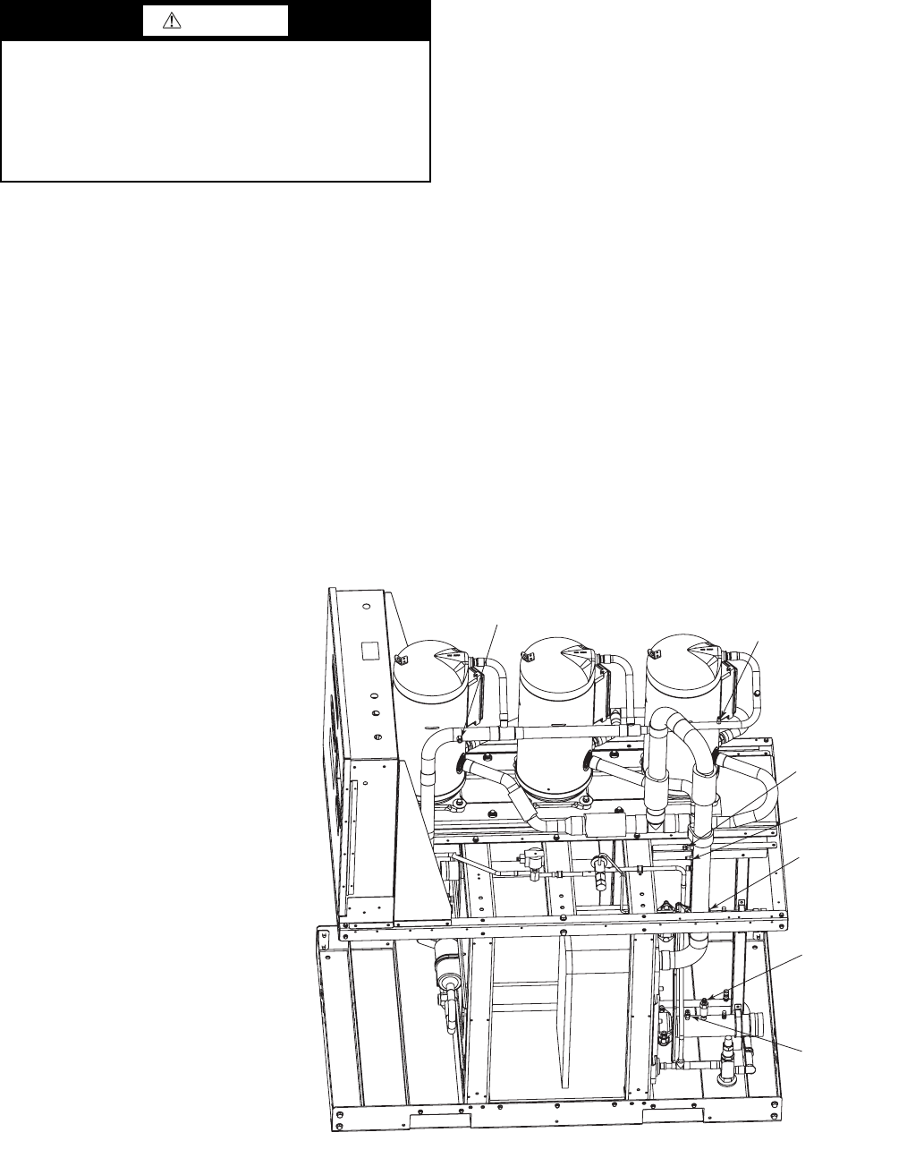
37
The strainers in front of the water/brine inlets of the heat
exchangers should be cleaned periodically, depending on con-
dition of the chiller water/brine.
Oil Charge
Puron refrigerant systems use a polyol ester (POE) oil. Use
only Carrier approved compressor oil. Oil should be visible in
compressor oil sight glass. An acceptable oil level is from 1/8 to
3/8 of sight glass. All compressors must be off when checking
oil level. Recommended oil level adjustment method is as
follows:
ADD OIL — Recover charge from the unit. Add oil to suction
line Schrader valve on tandem compressors sets and the com-
pressor Schrader on the trios. (See Fig. 21.) When oil can be
seen at the bottom of the sight glass, add oil in 5 oz increments
which is approximately 1/8 in oil level. Run all compressors for
20 minutes then shut off to check oil level. Repeat procedure
until acceptable oil level is present.
NOTE: Use only Carrier approved compressor oil. Approved
sources are:
Totaline . . . . . . . . . . . . . . . . . . . . . . 3MAF POE, P903-1601
Mobil . . . . . . . . . . . . . . . . . . . . . . . . . . . EAL Arctic 32-3MA
Uniqema . . . . . . . . . . . . . . . . . . . . . . . . . . . . . . RL32-3MAF
Do not reuse oil that has been drained out, or oil that has
been exposed to atmosphere.
Check Refrigerant Feed Components
FILTER DRIER — The function of the filter drier is to main-
tain a clean, dry system. The moisture indicator (described
below) indicates any need to change the filter drier. The filter
drier is a sealed-type drier. When the drier needs to be
changed, the entire filter drier must be replaced.
MOISTURE-LIQUID INDICATOR — The indicator is located
immediately ahead of the TXV to provide an indication of the
refrigerant moisture content. It also provides a sight glass for
refrigerant liquid. Clear flow of liquid refrigerant (at full unit
loading) indicates sufficient charge in the system. Bubbles in the
sight glass (at full unit loading) indicate an undercharged system
or the presence of noncondensables. Moisture in the system,
measured in parts per million (ppm), changes the color of the
indicator as follows:
Green (safe) —Moisture is below 75 ppm
Yellow-Green (caution) — 75 to 150 ppm
Yellow (wet) — above 150 ppm
The unit must be in operation at least 12 hours before the
moisture indicator gives an accurate reading, and must be in
contact with liquid refrigerant. At the first sign of moisture in
the system, change the corresponding filter drier.
THERMOSTATIC EXPANSION VALVE (TXV) — The
TXV controls the flow of liquid refrigerant to the cooler by
maintaining constant superheat of vapor leaving the cooler.
The valve(s) is activated by a temperature-sensing bulb(s)
strapped to the suction line(s).
The valve(s) is factory-set to maintain between 8° and 10° F
(4.4° and 5.6° C) of superheat leaving the cooler. Check the
superheat during operation after conditions have stabilized. If
necessary, adjust the superheat to prevent refrigerant floodback
to the compressor.
CAUTION
The compressor in a Puron® refigerant (R-410A) system
uses a polyol ester (POE) oil. This is extremely hygro-
scopic, meaning it absorbs water readily. POE oils can
absorb 15 times as much water as other oils designed for
HCFC and CFC refrigerants. Take all necessary precau-
tions to avoid exposure of the oil to the atmosphere. Failure
to do so could result in possible equipment damage.
HPS
DPT
RGT
SPT
EWT
(HIDDEN)
CWFS
LWT
Fig. 21 — Compressor Location — 30MP015-045 Units (30MPW045 Unit Shown)
LEGEND
CWFS — Chilled Water Flow Switch
DPT — Discharge Pressure Transducer
EWT — Entering Water Thermistor
HPS — High Pressure Switch
LWT — Leaving Water Thermistor
RGT — Return Gas Thermistor (Optional)
SPT — Suction Pressure Transducer
a30-5049
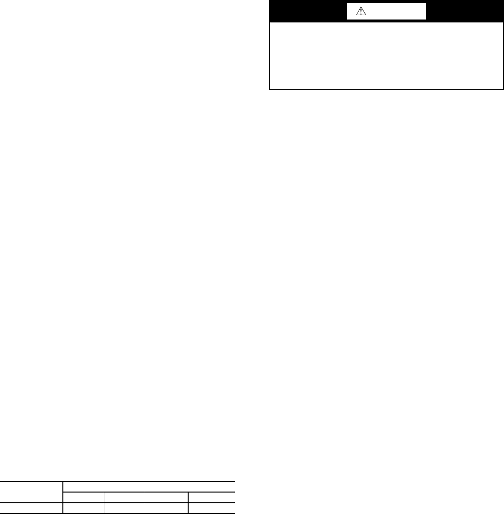
38
MINIMUM LOAD VALVE — On units equipped with the
factory-installed hot gas bypass option, a solenoid valve and
discharge bypass valve (minimum load valve) are located
between the discharge line and the cooler entering-refrigerant
line. The MBB cycles the solenoid to perform minimum load
valve function and the discharge bypass valve modulates to the
suction pressure set point of the valve. The bypass valve has an
adjustable opening setting between 95 to 115 psig (655 to
793 kPa). The factory setting is 105 psig (724 kPa).
The amount of capacity reduction achieved by the mini-
mum load valve is not adjustable. The total unit capacity with
the minimum load valve is shown in Table 19.
PRESSURE RELIEF DEVICES — All units have one pres-
sure relief device per circuit located in the liquid line which re-
lieves at 210 F (100 C).
The 30MPW unit does not have a condenser pressure relief
valve, because the brazed-plate condenser is not considered a
pressure vessel, as defined in ANSI/ASHRAE 15 (American
National Standards Institute/American Society of Heating,
Refrigerating, and Air Conditioning Engineers) safety code
requirements.
For 30MPA condenserless units, pressure relief devices de-
signed to relieve at the pressure determined in local codes,
must be field-supplied and installed in the discharge line piping
in accordance with ANSI/ASHRAE 15 safety code require-
ments. Additional pressure relief valves, properly selected,
must be field-supplied and installed to protect high side equip-
ment and may be required by applicable codes.
Most codes require that a relief valve be vented directly to
the outdoors. The vent line must not be smaller than the relief
valve outlet. Consult ANSI/ASHRAE 15 for detailed informa-
tion concerning layout and sizing of relief vent lines.
Check Unit Safeties
HIGH-PRESSURE SWITCH — A high-pressure switch is
provided to protect each compressor and refrigeration system
from unsafe high pressure conditions. See Table 31 for high-
pressure switch settings.
The high-pressure switch is mounted in the discharge line of
each circuit. If an unsafe, high-pressure condition should exist,
the switch opens and shuts off the affected circuit. The CSB
(current sensing board) senses the compressor feedback signal
and generates an appropriate alarm. The MBB prevents the cir-
cuit from restarting until the alert condition is reset. The switch
should open at the pressure corresponding to the appropriate
switch setting as shown in Table 31.
Table 31 — Factory Settings, High-Pressure
Switch (Fixed)
Clear the alarm using the scrolling marquee display. The
unit should restart after the compressor anti-short-cycle delay,
built into the unit control module, expires.
PRESSURE TRANSDUCERS — Each unit is equipped with
a suction and discharge pressure transducer. These inputs to the
MBB are not only used to monitor the status of the unit, but to
also maintain operation of the chiller within the compressor
manufacturer's specified limits. The input to the MBB from the
suction pressure transducer is also used to protect the compres-
sor from operating at low pressure conditions. If suction return
gas thermistors are installed, then additional low superheat
conditions are detected. In some cases, the unit may not be able
to run at full capacity. The control module will automatically
reduce the capacity of a circuit as needed to maintain specified
maximum/minimum operating pressures.
COOLER FREEZE-UP PROTECTION
The main base board (MBB) monitors cooler leaving fluid
temperature at all times. The MBB will rapidly remove stages
of capacity as necessary to prevent freezing conditions due to
the rapid loss of load or low cooler fluid flow.
When the cooler is exposed to lower temperatures (40 F
[4.4 C] or below), freeze-up protection is required using inhib-
ited ethylene or propylene glycol.
Thermistors — Electronic control uses up to five 5 k
thermistors to sense temperatures used to control operation of
the chiller. Thermistors EWT, LWT, RGTA, CNDE, CNDL,
and OAT are identical in their temperature and voltage drop
performance. The SPT space temperature thermistor has a
10 k input channel and it has a different set of temperature vs.
resistance and voltage drop performance. Resistance at various
temperatures are listed in Tables 32-35. For dual chiller opera-
tion, a dual chiller sensor is required which is a 5 k
thermistor.
REPLACING THERMISTORS (EWT, LWT, RGT, CNDE,
CNDL) — Add a small amount of thermal conductive grease
to the thermistor well and end of probe. For all probes, tighten
the retaining nut ¼ turn past finger tight. See Fig. 22.
THERMISTOR/TEMPERATURE SENSOR CHECK — A
high quality digital volt-ohmmeter is required to perform this
check.
1. Connect the digital voltmeter across the appropriate the-
mistor terminals at the J8 terminal strip on the main base
board (see Fig. 23).
2. Using the voltage reading obtained, read the sensor tem-
perature from Tables 32-35.
3. To check thermistor accuracy, measure temperature at
probe location with an accurate thermocouple-type tem-
perature measuring instrument. Insulate thermocouple to
avoid ambient temperatures from influencing reading.
Temperature measured by thermocouple and temperature
determined from thermistor voltage reading should be
close, ± 5° F (3° C) if care was taken in applying thermo-
couple and taking readings.
If a more accurate check is required, unit must be shut down
and thermistor removed and checked at a known temperature
(freezing point or boiling point of water) using either voltage
drop measured across thermistor at the J8 terminal, by deter-
mining the resistance with chiller shut down and thermistor
disconnected from J8. Compare the values determined with the
value read by the control in the Temperatures mode using the
scrolling marquee display.
Pressure Transducers — The suction and discharge
transducers are different part numbers and can be distinguished
by the color of the transducer body, suction (yellow) and dis-
charge (red). No pressure transducer calibration is required.
The transducers operate on a 5 vdc supply, which is generated
by the main base board (MBB). See Fig. 23 for transducer con-
nections to the J8 connector on the MBB.
TROUBLESHOOTING — If a transducer is suspected of be-
ing faulty, first check supply voltage to the transducer. Supply
voltage should be 5 vdc ± 0.2 v. If supply voltage is correct,
compare pressure reading displayed on the scrolling marquee
display module against pressure shown on a calibrated pressure
UNIT CUTOUT CUT-IN
Psig kPa Psig kPa
30MP015-045 650 4482 500 3447
WARNING
On medium temperature brine units, the anti-freeze solu-
tion must be properly mixed to prevent freezing at a tem-
perature of at least 15 F (8.3 C) below the leaving-fluid
temperature set point. Failure to provide the proper anti-
freeze solution mixture is considered abuse and may impair
or otherwise negatively impact the Carrier warranty.
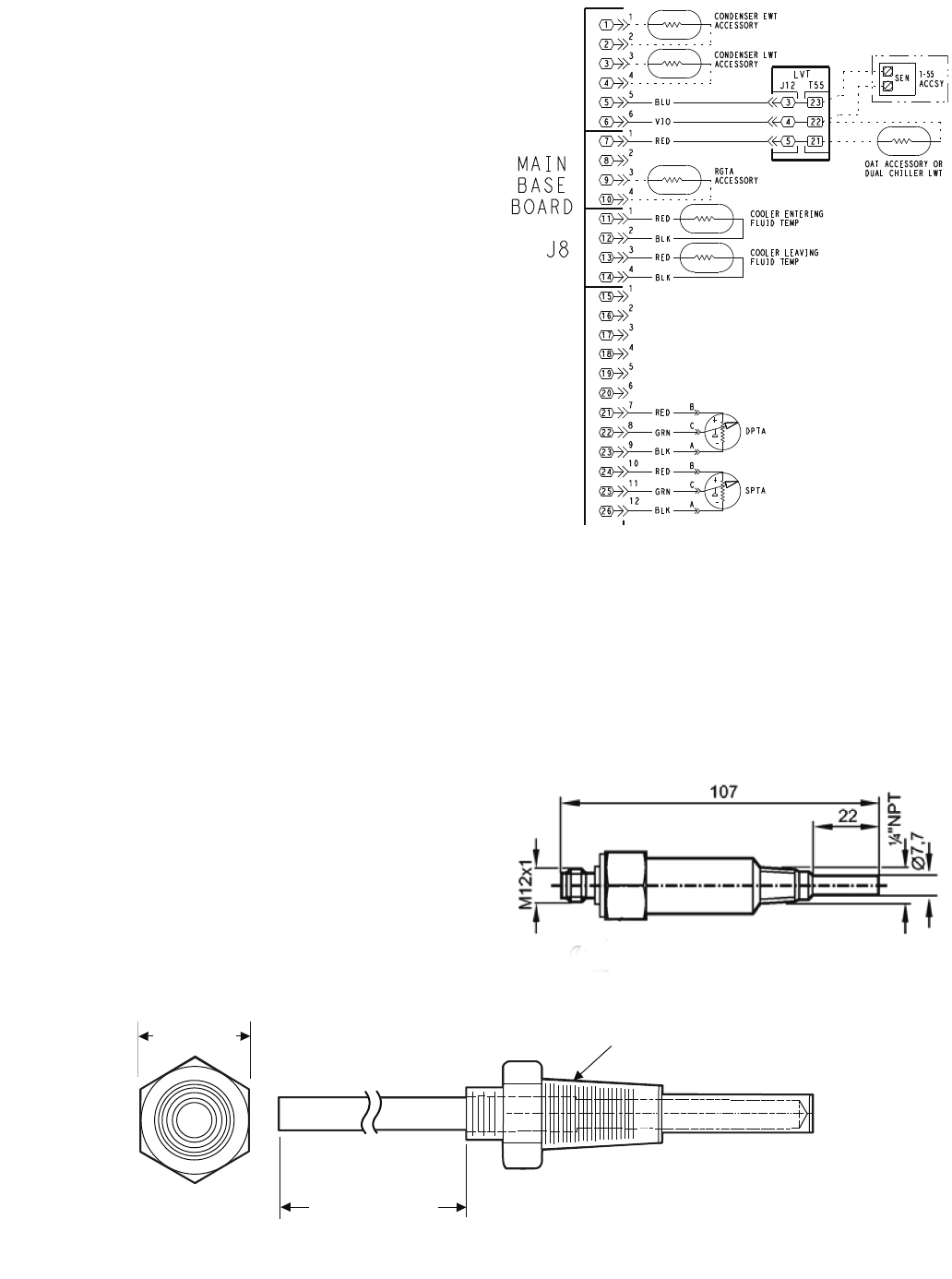
39
gauge. Pressure readings should be within ± 15 psig. If the
two readings are not reasonably close, replace the pressure
transducer.
Chilled Water Flow Switch — A factory-installed
flow switch is installed in the leaving fluid piping for all units.
This is a thermal-dispersion flow switch with no field adjust-
ments. The switch is set for approximately 0.5 ft/sec of flow.
The sensor tip houses two thermistors and a heater element.
One thermistor is located in the sensor tip, closest to the flow-
ing fluid. See Fig. 24. This thermistor is used to detect changes
in the flow velocity of the liquid. The second thermistor is
bonded to the cylindrical wall and is affected only by changes
in the temperature of the liquid. The thermistors are positioned
to be in close contact with the wall of the sensor probe and, at
the same time, to be kept separated from each other within the
confines of the probe.
In order to sense flow, it is necessary to heat one of the
thermistors in the probe. When power is applied, the tip of the
probe is heated. As the fluid starts to flow, heat will be carried
away from the sensor tip. Cooling of the first thermistor is a
function of how fast heat is conducted away by the flowing
liquid.
The difference in temperature between the two thermistors
provides a measurement of fluid velocity past the sensor probe.
When fluid velocity is high, more heat will be carried away
from the heated thermistor and the temperature differential will
be small. As fluid velocity decreases, less heat will be taken
from the heated thermistor and there will be an increase in tem-
perature differential.
When unit flow rate is above the minimum flow rate, then
the output is switched on, sending 24 vac to the MBB to prove
flow has been established.
For recommended maintenance, check the sensor tip for
build-up every 6 months. Clean the tip with a soft cloth. If
necessary, build-up (e.g., lime) can be removed with a common
vinegar cleansing agent.
The flow sensor cable is provided with (3) LEDs that indi-
cate if 24 vac power is present and also status of the switch
contacts. The LEDs are as follows:
• Green LED ON – 24 vac present
• One Yellow LED ON – Flow sensor switch OPEN
• Two Yellow LED ON – Flow sensor switch CLOSED
If nuisance trips of the sensor are occurring, follow the
steps below to correct the situation:
1. Check to confirm that the field-installed strainer is clean.
Use the blow-down valve provided or remove the screen
and clean it. For the case of VFD controlled pumps, en-
sure that the minimum speed setting has not been
changed.
2. Measure the pressure drop across the cooler and compare
this to the system requirements.
3. Verify that cable connections at the switch and at the ter-
minal block are secure.
4. Wrong pump motor rotation. Pump must rotate clockwise
when viewed from motor end of pump.
26
25
24
23
22
17
16
15
14
13
12
11
10
9
8
7
6
3
1
3
1
3
1
6
2
4
2
4
2
12
11
21
20
19
18
10
9
8
7
6
5
4
5
4
3
2
1
4
2
1
3
5
BASE
BOARD
J8
SPTA
-
+
DPTA
-
+
A
C
B
A
C
B
RED
GRN
RED
BLK
GRN
RED
BLK
BLU
VIO
LVT
5
4
3
22
23
21
T-55
ACCSY
SEN
OAT ACCESSORY OR
DUAL CHILLER LWT
CONDENSER EWT
ACCESSORY
CONDENSER LWT
ACCESSORY
BLK
RED COOLER ENTERING
FLUID TEMP
BLK
RED COOLER LEAVING
FLUID TEMP
RGTA
ACCESSORY
J12 T55
Fig. 23 — Thermistor Connections to
Main Base Board, J8 Connector
LEGEND
ACCSY — Accessory
DPT — Discharge Pressure Transducer
EWT — Entering Water Temperature
LWT — Leaving Water Temperature Sensor
LVT — Low Voltage Terminal
OAT — Outdoor Air Temperature Sensor
RGT — Return Gas Temperature Sensor
SEN — Sensor Terminal Block
SPT — Space Temperature Sensor
a30-5043
Fig. 24— Chilled Water Flow Switch
a30-499
NOTE: Dimensions are in millimeters.
5/8 in. HEX
6" MINIMUM
CLEARANCE FOR
THERMISTOR
REMOVAL
1/4-18 NPT
Fig. 22 — Thermistor Well

40
Table 32 — 5K Thermistor Temperatures (°F) vs. Resistance/Voltage Drop
(Voltage Drop for EWT, LWT, RGT, CNDE, CNDL, Dual Chiller, and OAT)
TEMP
(F)
VOLTAGE
DROP
(V)
RESISTANCE
(Ohms)
–25 3.699 98,010
–24 3.689 94,707
–23 3.679 91,522
–22 3.668 88,449
–21 3.658 85,486
–20 3.647 82,627
–19 3.636 79,871
–18 3.624 77,212
–17 3.613 74,648
–16 3.601 72,175
–15 3.588 69,790
–14 3.576 67,490
–13 3.563 65,272
–12 3.550 63,133
–11 3.536 61,070
–10 3.523 59,081
–9 3.509 57,162
–8 3.494 55,311
–7 3.480 53,526
–6 3.465 51,804
–5 3.450 50,143
–4 3.434 48,541
–3 3.418 46,996
–2 3.402 45,505
–1 3.386 44,066
03.369 42,679
13.352 41,339
23.335 40,047
33.317 38,800
43.299 37,596
53.281 36,435
63.262 35,313
73.243 34,231
83.224 33,185
93.205 32,176
10 3.185 31,202
11 3.165 30,260
12 3.145 29,351
13 3.124 28,473
14 3.103 27,624
15 3.082 26,804
16 3.060 26,011
17 3.038 25,245
18 3.016 24,505
19 2.994 23,789
20 2.972 23,096
21 2.949 22,427
22 2.926 21,779
23 2.903 21,153
24 2.879 20,547
25 2.856 19,960
26 2.832 19,393
27 2.808 18,843
28 2.784 18,311
29 2.759 17,796
30 2.735 17,297
31 2.710 16,814
32 2.685 16,346
33 2.660 15,892
34 2.634 15,453
35 2.609 15,027
36 2.583 14,614
37 2.558 14,214
38 2.532 13,826
39 2.506 13,449
40 2.480 13,084
41 2.454 12,730
42 2.428 12,387
43 2.402 12,053
44 2.376 11,730
45 2.349 11,416
46 2.323 11,112
47 2.296 10,816
48 2.270 10,529
49 2.244 10,250
50 2.217 9,979
51 2.191 9,717
52 2.165 9,461
53 2.138 9,213
54 2.112 8,973
55 2.086 8,739
56 2.060 8,511
57 2.034 8,291
58 2.008 8,076
TEMP
(F)
VOLTAGE
DROP
(V)
RESISTANCE
(Ohms)
59 1.982 7,686
60 1.956 7,665
61 1.930 7,468
62 1.905 7,277
63 1.879 7,091
64 1.854 6,911
65 1.829 6,735
66 1.804 6,564
67 1.779 6,399
68 1.754 6,238
69 1.729 6,081
70 1.705 5,929
71 1.681 5,781
72 1.656 5,637
73 1.632 5,497
74 1.609 5,361
75 1.585 5,229
76 1.562 5,101
77 1.538 4,976
78 1.516 4,855
79 1.493 4,737
80 1.470 4,622
81 1.448 4,511
82 1.426 4,403
83 1.404 4,298
84 1.382 4,196
85 1.361 4,096
86 1.340 4,000
87 1.319 3,906
88 1.298 3,814
89 1.278 3,726
90 1.257 3,640
91 1.237 3,556
92 1.217 3,474
93 1.198 3,395
94 1.179 3,318
95 1.160 3,243
96 1.141 3,170
97 1.122 3,099
98 1.104 3,031
99 1.086 2,964
100 1.068 2,898
101 1.051 2,835
102 1.033 2,773
103 1.016 2,713
104 0.999 2,655
105 0.983 2,597
106 0.966 2,542
107 0.950 2,488
108 0.934 2,436
109 0.918 2,385
110 0.903 2,335
111 0.888 2,286
112 0.873 2,239
113 0.858 2,192
114 0.843 2,147
115 0.829 2,103
116 0.815 2,060
117 0.801 2,018
118 0.787 1,977
119 0.774 1,937
120 0.761 1,898
121 0.748 1,860
122 0.735 1,822
123 0.723 1,786
124 0.710 1,750
125 0.698 1,715
126 0.686 1,680
127 0.674 1,647
128 0.663 1,614
129 0.651 1,582
130 0.640 1,550
131 0.629 1,519
132 0.618 1,489
133 0.608 1,459
134 0.597 1,430
135 0.587 1,401
136 0.577 1,373
137 0.567 1,345
138 0.557 1,318
139 0.548 1,291
140 0.538 1,265
141 0.529 1,240
142 0.520 1,214
TEMP
(F)
VOLTAGE
DROP
(V)
RESISTANCE
(Ohms)
143 0.511 1,190
144 0.502 1,165
145 0.494 1,141
146 0.485 1,118
147 0.477 1,095
148 0.469 1,072
149 0.461 1,050
150 0.453 1,029
151 0.445 1,007
152 0.438 986
153 0.430 965
154 0.423 945
155 0.416 925
156 0.408 906
157 0.402 887
158 0.395 868
159 0.388 850
160 0.381 832
161 0.375 815
162 0.369 798
163 0.362 782
164 0.356 765
165 0.350 750
166 0.344 734
167 0.339 719
168 0.333 705
169 0.327 690
170 0.322 677
171 0.317 663
172 0.311 650
173 0.306 638
174 0.301 626
175 0.296 614
176 0.291 602
177 0.286 591
178 0.282 581
179 0.277 570
180 0.272 561
181 0.268 551
182 0.264 542
183 0.259 533
184 0.255 524
185 0.251 516
186 0.247 508
187 0.243 501
188 0.239 494
189 0.235 487
190 0.231 480
191 0.228 473
192 0.224 467
193 0.220 461
194 0.217 456
195 0.213 450
196 0.210 445
197 0.206 439
198 0.203 434
199 0.200 429
200 0.197 424
201 0.194 419
202 0.191 415
203 0.188 410
204 0.185 405
205 0.182 401
206 0.179 396
207 0.176 391
208 0.173 386
209 0.171 382
210 0.168 377
211 0.165 372
212 0.163 367
213 0.160 361
214 0.158 356
215 0.155 350
216 0.153 344
217 0.151 338
218 0.148 332
219 0.146 325
220 0.144 318
221 0.142 311
222 0.140 304
223 0.138 297
224 0.135 289
225 0.133 282

41
Table 33 — 5K Thermistor Temperatures (°C) vs. Resistance/Voltage Drop
(Voltage Drop for EWT, LWT, RGT, CNDE, CNDL, Dual Chiller, and OAT)
TEMP
(C)
VOLTAGE
DROP
(V)
RESISTANCE
(Ohms)
–32 3.705 100,260
–31 3.687 94,165
–30 3.668 88,480
–29 3.649 83,170
–28 3.629 78,125
–27 3.608 73,580
–26 3.586 69,250
–25 3.563 65,205
–24 3.539 61,420
–23 3.514 57,875
–22 3.489 54,555
–21 3.462 51,450
–20 3.434 48,536
–19 3.406 45,807
–18 3.376 43,247
–17 3.345 40,845
–16 3.313 38,592
–15 3.281 38,476
–14 3.247 34,489
–13 3.212 32,621
–12 3.177 30,866
–11 3.140 29,216
–10 3.103 27,633
–9 3.065 26,202
–8 3.025 24,827
–7 2.985 23,532
–6 2.945 22,313
–5 2.903 21,163
–4 2.860 20,079
–3 2.817 19,058
–2 2.774 18,094
–1 2.730 17,184
02.685 16,325
12.639 15,515
22.593 14,749
32.547 14,026
42.500 13,342
52.454 12,696
62.407 12,085
72.360 11,506
82.312 10,959
92.265 10,441
10 2.217 9,949
11 2.170 9,485
12 2.123 9,044
13 2.076 8,627
14 2.029 8,231
TEMP
(C)
VOLTAGE
DROP
(V)
RESISTANCE
(Ohms)
15 1.982 7,855
16 1.935 7,499
17 1.889 7,161
18 1.844 6,840
19 1.799 6,536
20 1.754 6,246
21 1.710 5,971
22 1.666 5,710
23 1.623 5,461
24 1.580 5,225
25 1.538 5,000
26 1.497 4,786
27 1.457 4,583
28 1.417 4,389
29 1.378 4,204
30 1.340 4,028
31 1.302 3,861
32 1.265 3,701
33 1.229 3,549
34 1.194 3,404
35 1.160 3,266
36 1.126 3,134
37 1.093 3,008
38 1.061 2,888
39 1.030 2,773
40 0.999 2,663
41 0.969 2,559
42 0.940 2,459
43 0.912 2,363
44 0.885 2,272
45 0.858 2,184
46 0.832 2,101
47 0.807 2,021
48 0.782 1,944
49 0.758 1,871
50 0.735 1,801
51 0.713 1,734
52 0.691 1,670
53 0.669 1,609
54 0.649 1,550
55 0.629 1,493
56 0.610 1,439
57 0.591 1,387
58 0.573 1,337
59 0.555 1,290
60 0.538 1,244
61 0.522 1,200
TEMP
(C)
VOLTAGE
DROP
(V)
RESISTANCE
(Ohms)
62 0.506 1,158
63 0.490 1,118
64 0.475 1,079
65 0.461 1,041
66 0.447 1,006
67 0.433 971
68 0.420 938
69 0.407 906
70 0.395 876
71 0.383 836
72 0.371 805
73 0.360 775
74 0.349 747
75 0.339 719
76 0.329 693
77 0.319 669
78 0.309 645
79 0.300 623
80 0.291 602
81 0.283 583
82 0.274 564
83 0.266 547
84 0.258 531
85 0.251 516
86 0.244 502
87 0.237 489
88 0.230 477
89 0.223 466
90 0.217 456
91 0.211 446
92 0.204 436
93 0.199 427
94 0.193 419
95 0.188 410
96 0.182 402
97 0.177 393
98 0.172 385
99 0.168 376
100 0.163 367
101 0.158 357
102 0.154 346
103 0.150 335
104 0.146 324
105 0.142 312
106 0.138 299
107 0.134 285

42
Table 34 — 10K Thermistor Temperature (°F) vs. Resistance/Voltage Drop
(For SPT)
TEMP
(F)
VOLTAGE
DROP
(V)
RESISTANCE
(Ohms)
–25 4.758 196,453
–24 4.750 189,692
–23 4.741 183,300
–22 4.733 177,000
–21 4.724 171,079
–20 4.715 165,238
–19 4.705 159,717
–18 4.696 154,344
–17 4.686 149,194
–16 4.676 144,250
–15 4.665 139,443
–14 4.655 134,891
–13 4.644 130,402
–12 4.633 126,183
–11 4.621 122,018
–10 4.609 118,076
–9 4.597 114,236
–8 4.585 110,549
–7 4.572 107,006
–6 4.560 103,558
–5 4.546 100,287
–4 4.533 97,060
–3 4.519 94,020
–2 4.505 91,019
–1 4.490 88,171
04.476 85,396
14.461 82,729
24.445 80,162
34.429 77,662
44.413 75,286
54.397 72,940
64.380 70,727
74.363 68,542
84.346 66,465
94.328 64,439
10 4.310 62,491
11 4.292 60,612
12 4.273 58,781
13 4.254 57,039
14 4.235 55,319
15 4.215 53,693
16 4.195 52,086
17 4.174 50,557
18 4.153 49,065
19 4.132 47,627
20 4.111 46,240
21 4.089 44,888
22 4.067 43,598
23 4.044 42,324
24 4.021 41,118
25 3.998 39,926
26 3.975 38,790
27 3.951 37,681
28 3.927 36,610
29 3.903 35,577
30 3.878 34,569
31 3.853 33,606
32 3.828 32,654
33 3.802 31,752
34 3.776 30,860
35 3.750 30,009
36 3.723 29,177
37 3.697 28,373
38 3.670 27,597
39 3.654 26,838
40 3.615 26,113
41 3.587 25,396
42 3.559 24,715
43 3.531 24,042
44 3.503 23,399
45 3.474 22,770
46 3.445 22,161
47 3.416 21,573
48 3.387 20,998
49 3.357 20,447
50 3.328 19,903
51 3.298 19,386
52 3.268 18,874
53 3.238 18,384
54 3.208 17,904
55 3.178 17,441
56 3.147 16,991
57 3.117 16,552
58 3.086 16,131
59 3.056 15,714
60 3.025 15,317
TEMP
(F)
VOLTAGE
DROP
(V)
RESISTANCE
(Ohms)
61 2.994 14,925
62 2.963 14,549
63 2.932 14,180
64 2.901 13,824
65 2.870 13,478
66 2.839 13,139
67 2.808 12,814
68 2.777 12,493
69 2.746 12,187
70 2.715 11,884
71 2.684 11,593
72 2.653 11,308
73 2.622 11,031
74 2.592 10,764
75 2.561 10,501
76 2.530 10,249
77 2.500 10,000
78 2.470 9,762
79 2.439 9,526
80 2.409 9,300
81 2.379 9,078
82 2.349 8,862
83 2.319 8,653
84 2.290 8,448
85 2.260 8,251
86 2.231 8,056
87 2.202 7,869
88 2.173 7,685
89 2.144 7,507
90 2.115 7,333
91 2.087 7,165
92 2.059 6,999
93 2.030 6,838
94 2.003 6,683
95 1.975 6,530
96 1.948 6,383
97 1.921 6,238
98 1.894 6,098
99 1.867 5,961
100 1.841 5,827
101 1.815 5,698
102 1.789 5,571
103 1.763 5,449
104 1.738 5,327
105 1.713 5,210
106 1.688 5,095
107 1.663 4,984
108 1.639 4,876
109 1.615 4,769
110 1.591 4,666
111 1.567 4,564
112 1.544 4,467
113 1.521 4,370
114 1.498 4,277
115 1.475 4,185
116 1.453 4,096
117 1.431 4,008
118 1.409 3,923
119 1.387 3,840
120 1.366 3,759
121 1.345 3,681
122 1.324 3,603
123 1.304 3,529
124 1.284 3,455
125 1.264 3,383
126 1.244 3,313
127 1.225 3,244
128 1.206 3,178
129 1.187 3,112
130 1.168 3,049
131 1.150 2,986
132 1.132 2,926
133 1.114 2,866
134 1.096 2,809
135 1.079 2,752
136 1.062 2,697
137 1.045 2,643
138 1.028 2,590
139 1.012 2,539
140 0.996 2,488
141 0.980 2,439
142 0.965 2,391
143 0.949 2,343
144 0.934 2,297
145 0.919 2,253
146 0.905 2,209
TEMP
(F)
VOLTAGE
DROP
(V)
RESISTANCE
(Ohms)
147 0.890 2,166
148 0.876 2,124
149 0.862 2,083
150 0.848 2,043
151 0.835 2,003
152 0.821 1,966
153 0.808 1,928
154 0.795 1,891
155 0.782 1,855
156 0.770 1,820
157 0.758 1,786
158 0.745 1,752
159 0.733 1,719
160 0.722 1,687
161 0.710 1,656
162 0.699 1,625
163 0.687 1,594
164 0.676 1,565
165 0.666 1,536
166 0.655 1,508
167 0.645 1,480
168 0.634 1,453
169 0.624 1,426
170 0.614 1,400
171 0.604 1,375
172 0.595 1,350
173 0.585 1,326
174 0.576 1,302
175 0.567 1,278
176 0.558 1,255
177 0.549 1,233
178 0.540 1,211
179 0.532 1,190
180 0.523 1,169
181 0.515 1,148
182 0.507 1,128
183 0.499 1,108
184 0.491 1,089
185 0.483 1,070
186 0.476 1,052
187 0.468 1,033
188 0.461 1,016
189 0.454 998
190 0.447 981
191 0.440 964
192 0.433 947
193 0.426 931
194 0.419 915
195 0.413 900
196 0.407 885
197 0.400 870
198 0.394 855
199 0.388 841
200 0.382 827
201 0.376 814
202 0.370 800
203 0.365 787
204 0.359 774
205 0.354 762
206 0.349 749
207 0.343 737
208 0.338 725
209 0.333 714
210 0.328 702
211 0.323 691
212 0.318 680
213 0.314 670
214 0.309 659
215 0.305 649
216 0.300 639
217 0.296 629
218 0.292 620
219 0.288 610
220 0.284 601
221 0.279 592
222 0.275 583
223 0.272 574
224 0.268 566
225 0.264 557
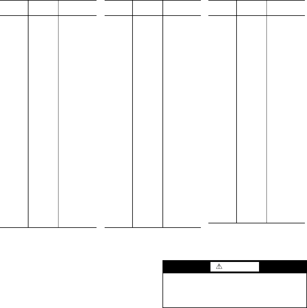
43
Table 35 — 10K Thermistor Temperature (°C) vs. Resistance/Voltage Drop
(For SPT)
Strainer — Periodic cleaning of the required field-installed
strainer is required. Pressure drop across strainer in excess of
3 psi (21 kPa) indicates the need for cleaning. Normal (clean)
pressure drop is approximately 1 psi (6.9 kPa). Open the
blowdown valve to clean the strainer. If required, shut the chill-
er down and remove the strainer screen to clean. When strainer
has been cleaned, enter ‘YES’ for Strainer Maintenance Done
(Run Status
PM
S.T.MN.
Replacing Defective Modules — The Comfort-
Link™ replacement modules are shown in Table 36. If the main
base board (MBB) has been replaced, verify that all configura-
tion data is correct. Follow the Configuration mode table and
verify that all items under sub-modes UNIT, OPT1 and OPT2
are correct. Any additional field-installed accessories or op-
tions (RSET, SLCT sub-modes) should also be verified as well
as any specific time and maintenance schedules.
Refer to the Start-Up Checklist for 30MP Liquid Chillers
(completed at time of original start-up) found in the job folder.
This information is needed later in this procedure. If the check-
list does not exist, fill out the current information in the Config-
uration mode on a new checklist. Tailor the various options and
configurations as needed for this particular installation.
1. Check that all power to unit is off. Carefully disconnect
all wires from the defective module by unplugging its
connectors.
2. Remove the defective module by removing its mounting
screws with a Phillips screwdriver, and removing the
module from the control box. Save the screws later use.
3. Verify that the instance jumper (MBB) or address switch-
es (all other modules) exactly match the settings of the
defective module.
NOTE: Handle boards by mounting standoffs only to
avoid electrostatic discharge.
4. Package the defective module in the carton of the new
module for return to Carrier.
5. Mount the new module in the unit’s control box using a
Phillips screwdriver and the screws saved in Step 2.
TEMP
(C)
VOLTAGE
DROP
(V)
RESISTANCE
(Ohms)
–32 4.762 200,510
–31 4.748 188,340
–30 4.733 177,000
–29 4.716 166,342
–28 4.700 156,404
–27 4.682 147,134
–26 4.663 138,482
–25 4.644 130,402
–24 4.624 122,807
–23 4.602 115,710
–22 4.580 109,075
–21 4.557 102,868
–20 4.533 97,060
–19 4.508 91,588
–18 4.482 86,463
–17 4.455 81,662
–16 4.426 77,162
–15 4.397 72,940
–14 4.367 68,957
–13 4.335 65,219
–12 4.303 61,711
–11 4.269 58,415
–10 4.235 55,319
–9 4.199 52,392
–8 4.162 49,640
–7 4.124 47,052
–6 4.085 44,617
–5 4.044 42,324
–4 4.003 40,153
–3 3.961 38,109
–2 3.917 36,182
–1 3.873 34,367
03.828 32,654
13.781 31,030
23.734 29,498
33.686 28,052
43.637 26,686
53.587 25,396
63.537 24,171
73.485 23,013
83.433 21,918
93.381 20,883
10 3.328 19,903
11 3.274 18,972
12 3.220 18,090
13 3.165 17,255
14 3.111 16,464
TEMP
(C)
VOLTAGE
DROP
(V)
RESISTANCE
(Ohms)
15 3.056 15,714
16 3.000 15,000
17 2.944 14,323
18 2.889 13,681
19 2.833 13,071
20 2.777 12,493
21 2.721 11,942
22 2.666 11,418
23 2.610 10,921
24 2.555 10,449
25 2.500 10,000
26 2.445 9,571
27 2.391 9,164
28 2.337 8,776
29 2.284 8,407
30 2.231 8,056
31 2.178 7,720
32 2.127 7,401
33 2.075 7,096
34 2.025 6,806
35 1.975 6,530
36 1.926 6,266
37 1.878 6,014
38 1.830 5,774
39 1.784 5,546
40 1.738 5,327
41 1.692 5,117
42 1.648 4,918
43 1.605 4,727
44 1.562 4,544
45 1.521 4,370
46 1.480 4,203
47 1.439 4,042
48 1.400 3,889
49 1.362 3,743
50 1.324 3,603
51 1.288 3,469
52 1.252 3,340
53 1.217 3,217
54 1.183 3,099
55 1.150 2,986
56 1.117 2,878
57 1.086 2,774
58 1.055 2,675
59 1.025 2,579
60 0.996 2,488
61 0.968 2,400
TEMP
(C)
VOLTAGE
DROP
(V)
RESISTANCE
(Ohms)
62 0.940 2,315
63 0.913 2,235
64 0.887 2,157
65 0.862 2,083
66 0.837 2,011
67 0.813 1,943
68 0.790 1,876
69 0.767 1,813
70 0.745 1,752
71 0.724 1,693
72 0.703 1,637
73 0.683 1,582
74 0.663 1,530
75 0.645 1,480
76 0.626 1,431
77 0.608 1,385
78 0.591 1,340
79 0.574 1,297
80 0.558 1,255
81 0.542 1,215
82 0.527 1,177
83 0.512 1,140
84 0.497 1,104
85 0.483 1,070
86 0.470 1,037
87 0.457 1,005
88 0.444 974
89 0.431 944
90 0.419 915
91 0.408 889
92 0.396 861
93 0.386 836
94 0.375 811
95 0.365 787
96 0.355 764
97 0.345 742
98 0.336 721
99 0.327 700
100 0.318 680
101 0.310 661
102 0.302 643
103 0.294 626
104 0.287 609
105 0.279 592
106 0.272 576
107 0.265 561
WARNING
Electrical shock can cause personal injury and death. Shut
off all power to this equipment during installation. There
may be more than one disconnect switch. Tag all discon-
nect locations to alert others not to restore power until work
is completed.
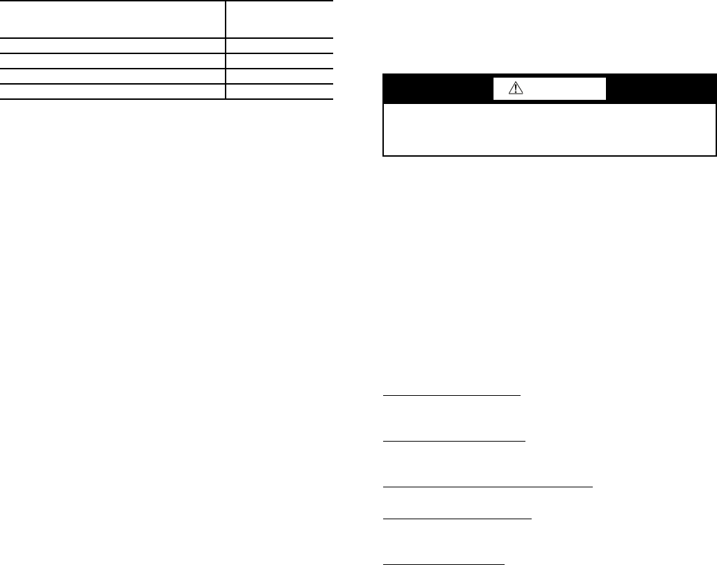
44
6. Reinstall all module connectors. For accessory Naviga-
tor™ device replacement, make sure the plug is installed
at TB3 in the LEN connector.
7. Carefully check all wiring connections before restoring
power.
8. Verify the ENABLE/OFF/REMOTE CONTACT switch
is in the OFF position.
9. Restore control power. Verify that all module red LEDs
blink in unison. Verify that all green LEDs are blinking
and that the scrolling marquee or Navigator™ display is
communicating correctly.
10. Verify all configuration information, settings, set points
and schedules. Return the ENABLE/OFF/REMOTE
CONTACT switch to its previous position.
Table 36 — Replacement Modules
MAINTENANCE
Recommended Maintenance Schedule — The fol-
lowing are only recommended guidelines. Jobsite conditions
may dictate that maintenance schedule is performed more often
than recommended.
Routine:
Every month:
• Check moisture indicating sight glass for possible refrig-
erant loss and presence of moisture.
Every 3 months (for all machines):
• Check refrigerant charge.
• Check all refrigerant joints and valves for refrigerant
leaks, repair as necessary.
• Check chilled water flow switch operation.
• Check compressor oil level.
Every 12 months (for all machines):
• Check all electrical connections, tighten as necessary.
• Inspect all contactors and relays, replace as necessary.
• Check accuracy of thermistors, replace if greater than
± 2° F (1.2° C) variance from calibrated thermometer.
• Check to be sure that the proper concentration of anti-
freeze is present in the chilled water loop, if applicable.
• Verify that the chilled water loop is properly treated.
• Check refrigerant filter driers for excessive pressure
drop, replace as necessary.
• Check chilled water and condenser strainers, clean as
necessary.
• Perform Service Test to confirm operation of all
components.
• Check for excessive cooler approach (Leaving Chilled
Water Temperature — Saturated Suction Temperature)
which may indicate fouling. Clean evaporator if
necessary.
TROUBLESHOOTING
Complete Unit Stoppage and Restart — Possi-
ble causes for unit stoppage and reset methods are shown be-
low and in Table 37. Refer to Fig. 3-7 for component arrange-
ment and control wiring diagrams.
GENERAL POWER FAILURE — After power is restored,
restart is automatic through normal MBB start-up.
UNIT ENABLE-OFF-REMOTE CONTACT SWITCH IS
OFF — When the switch is OFF, the unit will stop immediate-
ly. Place the switch in the ENABLE position for local switch
control or in the REMOTE CONTACT position for control
through remote contact closure.
CHILLED FLUID PROOF-OF-FLOW SWITCH OPEN —
After the problem causing the loss of flow has been corrected,
reset is manual by resetting the alarm with the scrolling
marquee.
OPEN 24-V CONTROL CIRCUIT BREAKER(S) — De-
termine the cause of the failure and correct. Reset circuit break-
er(s). Restart is automatic after MBB start-up cycle is com-
plete.
COOLING LOAD SATISFIED — Unit shuts down when
cooling load has been satisfied. Unit restarts when required to
satisfy leaving fluid temperature set point.
THERMISTOR FAILURE — If a thermistor fails in either an
open or shorted condition, the unit will be shut down. Replace
EWT, or LWT as required. Unit restarts automatically, but must
be reset manually by resetting the alarm with the scrolling
marquee.
LOW SATURATED SUCTION — Several conditions can
lead to low saturated suction alarms and the chiller controls
have several override modes built in which will attempt to keep
the chiller from shutting down. Low fluid flow, low refrigerant
charge and plugged filter driers are the main causes for this
condition. To avoid permanent damage and potential freezing
of the system, do NOT repeatedly reset these alert and/or alarm
conditions without identifying and correcting the cause(s).
COMPRESSOR SAFETIES — The 30MP units with Com-
fortLink™ controls include a compressor protection board that
protects the operation of each of the compressors. Each board
senses the presence or absence of current to each compressor.
If there is a command for a compressor to run and there is
no current, then one of the following safeties or conditions
have turned the compressor off:
Compressor Overcurrent — All compressors have internal
line breaks or a motor protection device located in the com-
pressor electrical box.
Compressor Short Circuit — There will not be current if the
compressor circuit breaker that provides short circuit protection
has tripped.
Compressor Motor Over Temperature — The internal line-
break or over temperature switch has opened.
High-Pressure Switch Trip — The high pressure switch has
opened. See Table 31 for the factory settings for the fixed high
pressure switch.
ASTP Protection Trip — All non-digital Copeland compres-
sors are equipped with an advanced scroll temperature protec-
tion (ASTP). A label located above the terminal box identifies
models that contain this technology. See Fig. 25.
Advanced scroll temperature protection is a form of internal
discharge temperature protection that unloads the scroll com-
pressor when the internal temperature reaches approximately
300 F. At this temperature, an internal bi-metal disk valve
opens and causes the scroll elements to separate, which stops
compression. Suction and discharge pressures balance while
the motor continues to run. The longer the compressor runs un-
loaded, the longer it must cool before the bi-metal disk resets.
See Fig. 26 for approximate reset times.
MODULE
REPLACEMENT
PART NO.
(with Software)
Main Base Board (MBB) 30MP500346
Scrolling Marquee Display HK50AA031
Energy Management Module (EMM) 30GT515218
Navigator Display HK50AA033 CAUTION
If unit stoppage occurs more than once as a result of any of
the safety devices listed, determine and correct cause
before attempting another restart.
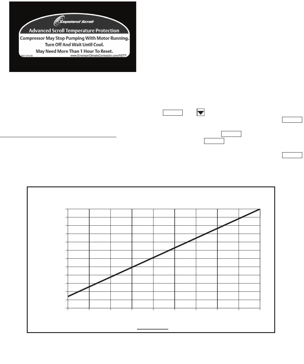
45
To manually reset ASTP, the compressor should be stopped
and allowed to cool. If the compressor is not stopped, the motor
will run until the motor protector trips, which occurs up to
90 minutes later. Advanced scroll temperature protection will
reset automatically before the motor protector resets, which
may take up to 2 hours.
High Discharge Gas Temperature Protection — Units
equipped with optional digital compressors have an additional
thermistor located on the discharge line, If discharge tempera-
ture exceeds 265 F (129.4 C), the digital compressor will be
shut off.
Alarms will also occur if the current sensor board malfunc-
tions or is not properly connected to its assigned digital input. If
the compressor is commanded OFF and the current sensor
reads ON, an alert is generated. This will indicate that a com-
pressor contactor has failed closed. In this case, a special mode,
Compressor Stuck on Control, will be enabled and all other
compressors will be turned off. An alarm will then be enabled
to indicate that service is required. Outdoor fans will continue
to operate. The condenser output is turned on immediately.
Alarms and Alerts — These are warnings of abnormal
or fault conditions, and may cause either one circuit or the
whole unit to shut down. They are assigned code numbers as
described in Table 38.
Automatic alarms will reset without operator intervention if
the condition corrects itself. The following method must be
used to reset manual alarms:
Before resetting any alarm, first determine the cause of the
alarm and correct it. Enter the Alarms mode indicated by the
LED on the side of the scrolling marquee display. Press
and until the sub-menu item RCRN “RESET
ALL CURRENT ALARMS” is displayed. Press .
The control will prompt the user for a password, by displaying
PASS and WORD. Press to display the default pass-
word, 1111. Press for each character. If the password
has been changed, use the arrow keys to change each individu-
al character. Toggle the display to “YES” and press .
The alarms will be reset.
Fig. 25 — Advanced Scroll Temperature
Protection Label
ENTER
ENTER
ENTER
ENTER
ENTER
Fig. 26 — Recommended Minimum Cool Down Time After Compressor is Stopped*
0
10
20
30
40
50
60
70
80
90
100
110
120
0 102030405060708090
Compressor Unloaded Run Time (Minutes)
Recommended Cooling Time
(Minutes)
*Times are approximate.
NOTE: Various factors, including high humidity, high ambient temperature,
and the presence of a sound blanket will increase cool-down times.

46
Table 37 — Troubleshooting
SYMPTOMS CAUSE REMEDY
Compressor Cycles
Off on Loss of Charge
Loss of charge control. Acting erratically. Repair leak and recharge.
Replace control.
Low refrigerant charge Add refrigerant.
Low suction temperature Raise cooler leaving fluid temperature set point.
Compressor Cycles Off on Out
of Range Condition
Thermistor failure Replace thermistor.
System load was reduced faster than controller could
remove stages
Unit will restart after fluid temperature rises back into the
control band. Avoid rapidly removing system load or
increase loop volume.
Temperature controller deadband setting is too low Raise deadband setting.
Compressor Shuts Down on
High-Pressure Control
High-pressure control acting erratically Replace control.
Noncondensables in system Purge system.
Condenser scaled/dirty Clean condenser.
Fans in remote condensing unit (30MPA only) not operating Repair or replace if defective.
System overcharged with refrigerant Reduce charge.
Unit Operates Too Long
or Continuously
Low refrigerant charge Add refrigerant.
Control contacts fused Replace control.
Air in system Purge system.
Partially plugged or plugged expansion valve or filter drier Clean or replace as needed.
Defective insulation Replace or repair as needed.
Service load Keep doors and windows closed.
Damaged compressor Check compressor and replace if necessary.
Unusual or Loud System
Noises
Piping vibration Support piping as required.
Check for loose pipe connections or damaged compressor
Expansion valve hissing Add refrigerant.
Check for plugged liquid line filter drier.
Compressor noisy Replace compressor (worn bearings).
Check for loose compressor holddown bolts.
Compressor Loses Oil Leak in system Repair leak.
Mechanical damage (Failed seals or broken scrolls) Replace compressor.
Oil trapped in line Check piping for oil traps.
Hot Liquid Line Shortage of refrigerant due to leak Repair leak and recharge.
Frosted Liquid Line Restricted filter drier Replace filter drier.
Frosted Suction Line Expansion valve admitting excess refrigerant (note: this is a
normal condition for brine applications)
Replace valve if defective.
Stuck TXV Replace valve if defective.
Freeze-Up Improper charging Make sure a full quantity of fluid is flowing through the cooler
while charging, and suction pressure in cooler is equal to or
greater than pressure corresponding to 32 F (0° C).
System not drained for winter shutdown Recommended that system be filled with an appropriate gly-
col mixture to prevent freezing of pumps and fluid tubing.
Loose Thermistor Verify thermistors are fully inserted in wells.

47
Table 38 — Alarm and Alert Codes
ALARM/
ALERT
CODE
ALARM
OR
ALERT
DESCRIPTION
WHY WAS THIS
ALARM
GENERATED?
ACTION TAKEN
BY CONTROL
RESET
METHOD
PROBABLE
CAUSE
A048 Alarm Circuit A Compressor
Availability Alarm
Two compressors on circuit
failed Circuit shut down Manual Only one compressor
operating.
T051 Alert Circuit A, Compressor 1
Failure
Compressor feedback signal
does not match relay state
Compressor A1 shut
down. Manual
High-pressure switch open,
faulty CSB, loss of condenser
flow, filter drier plugged, non-
condensables, operation
beyond capability.
A051 Alarm Circuit A, Compressor 1
Failure
Respective current sensor
board (CSB) feedback signal
is ON when the compressor
should be off
Unit shut down Manual
High-pressure switch open,
faulty CSB, loss of condenser
flow, filter drier plugged, non-
condensables, operation
beyond capability.
T052 Alert Circuit A, Compressor 2
Failure
Compressor feedback signal
does not match relay state
Compressor A2 shut
down. Manual
High-pressure switch open,
faulty CSB, loss of condenser
flow, filter drier plugged, non-
condensables, operation
beyond capability.
A052 Alarm Circuit A, Compressor 2
Failure
Respective current sensor
board (CSB) feedback signal
is ON when the compressor
should be off
Unit shut down Manual
High-pressure switch open,
faulty CSB, loss of condenser
flow, filter drier plugged, non-
condensables, operation
beyond capability.
T053 Alert Circuit A, Compressor 3
Failure
Compressor feedback signal
does not match relay state
Compressor A3 shut
down. Manual
High-pressure switch open,
faulty CSB, loss of condenser
flow, filter drier plugged, non-
condensables, operation
beyond capability.
A053 Alarm Circuit A, Compressor 3
Failure
Respective current sensor
board (CSB) feedback signal
is ON when the compressor
should be off
Unit shut down Manual
High-pressure switch open,
faulty CSB, loss of condenser
flow, filter drier plugged, non-
condensables, operation
beyond capability.
A060 Alarm Cooler Leaving Fluid
Thermistor Failure
Thermistor outside range of
–40 to 245 F (–40 to 118 C)
Chiller shut down
immediately Automatic Thermistor failure, damaged
cable/wire or wiring error.
A061 Alarm Cooler Entering Fluid
Thermistor Failure
Thermistor outside range of
–40 to 245 F (–40 to 118 C)
Chiller shut down
immediately Automatic Thermistor failure, damaged
cable/wire or wiring error.
T062 Alert Condenser Leaving Fluid
Thermistor Failure
Thermistor outside range of
–40 to 245 F (–40 to 118 C)
Alert only.
No action taken.
Automatic Thermistor failure, damaged
cable/wire or wiring error.
T063 Alert Condenser Entering Fluid
Thermistor Failure
Thermistor outside range of
–40 to 245 F (–40 to 118 C)
Alert only.
No action taken.
Automatic Thermistor failure, damaged
cable/wire or wiring error.
T068 None Circuit A Return Gas
Thermistor Failure
If return gas sensors are
enabled (RG.EN) and
thermistor is outside range of
–40 to 245 F (–40 to 118 C)
Circuit A shut down Automatic Thermistor failure, damaged
cable/wire or wiring error.
T073 Alert Outside Air Thermistor
Failure
Thermistor outside range of
–40 to 245 F (–40 to 118 C)
(if enabled)
Temperature reset
disabled. Chiller runs
under normal control/set
points.
Automatic Thermistor failure, damaged
cable/wire or wiring error.
T074 Alert Space Temperature/Dual Chiller
Thermistor Failure
Thermistor outside range of
–40 to 245 F (–40 to 118 C)
(if enabled)
Temperature reset
disabled. Chiller runs
under normal control/set
points.
Automatic Thermistor failure, damaged
cable/wire or wiring error.
A077 Alarm
Circuit A Saturated
Suction Temperature
exceeds Cooler Leaving
Fluid Temperature
Faulty expansion valve,
suction pressure transducer
or leaving fluid thermistor.
Circuit A shutdown after
pumpdown complete. Manual
Faulty expansion valve or
suction pressure transducer
or leaving fluid thermistor.
T079 Alert Lead/Lag LWT
Thermistor Failure
Thermistor outside range of
–40 to 245 F (–40 to 118 C)
Chiller runs as a stand
alone machine Automatic
Dual LWT thermistor failure,
damaged cable/wire or
wiring error.
A090 Alarm Circuit A Discharge
Pressure Transducer Failure Outside of range (0 - 667 psig) Circuit A shut down Automatic
Transducer failure, poor
connection to MBB, or wiring
damage/error.
A092 Alarm Circuit A Suction
Pressure Transducer Failure Outside of range (0 - 420 psig) Circuit A shut down Automatic
Transducer failure, poor
connection to MBB, or wiring
damage/error.
T094 Alert Discharge Gas
Thermistor Failure
Discharge thermistor (DTT) is
either open or shorted
Digital compressor shut
down. Automatic Thermistor failure, damaged
cable/wire or wiring error.
A110 Alarm Circuit A Loss of Charge
If the compressors are off
and discharge pressure
reading is < 26 psig for
30 sec.
Circuit not allowed to
start. Manual Refrigerant leak or
transducer failure
A112 Alarm Circuit A High Saturated
Suction Temperature
Circuit saturated suction
temperature pressure
transducer > 70 F (21.1 C)
for 5 minutes
Circuit shut down Manual
Faulty Expansion valve,
faulty suction pressure
transducer or high entering
fluid temperature.
A114 Alarm Circuit A Low Suction
Superheat
Suction superheat is
less than 5° F (2.8 C) for 5
minutes. (if RGT installed)
Circuit A shut down.
Automatic restart
after first daily
occurrence.
Manual restart
thereafter.
Faulty expansion valve,
faulty suction pressure
transducer, faulty suction gas
thermistor, circuit
overcharged

48
Table 38 — Alarm and Alert Codes (cont)
See legend on page 51.
ALARM/
ALERT
CODE
ALARM
OR
ALERT
DESCRIPTION
WHY WAS THIS
ALARM
GENERATED?
ACTION TAKEN
BY CONTROL
RESET
METHOD
PROBABLE
CAUSE
A116 Alarm Circuit A Low Cooler
Suction Temperature
Mode 7 caused the com-
pressor to unload 6 consecu-
tive times with less than a
30-minute interval between
each circuit shutdown.
Circuit shut down Manual
Faulty expansion valve, low
refrigerant charge, plugged
filter drier, faulty suction
pressure transducer, low
cooler fluid flow
A122 Alarm High Pressure Switch
Trip Circuit A
High Pressure A Switch
Input opento MBB Circuit shut down Manual Faulty transducer/high
pressure switch.
A126 Alarm Circuit A High
Discharge Pressure
SCT >Maximum condensing
temperature from operating
envelope
Circuit shut down
Automatic, only
after first 3 daily
occurrences.
Manual reset
thereafter. Read-
ing from OAT sen-
sor must drop 5 F
(2.8 C) before
restart
Faulty transducer/high
pressure switch, low/
restricted condenser
airflow
T133 Alert Circuit A Low Suction
Pressure
Suction pressure below
34 psig for 8 seconds or
below 23 psig
Circuit shut down
Automatic
restart after first
daily occurrence.
Manual restart
thereafter.
Faulty or plugged EXV, low
refrigerant charge, EXV out
of adjustment, liquid
line valve partially closed
A140 Alert Reverse Rotation
Detected
Incoming chiller power leads
not phased correctly
Chiller not allowed to
start. Manual
Reverse any two incoming
power leads to correct. Check
for correct fan rotation first.
A150 Alarm Emergency Stop CCN emergency stop
command received
Chiller shutdown
without going through
pumpdown.
Automatic once
CCN command for
EMSTOP returns to
normal
CCN Network
command.
A151 Alarm Illegal Configuration One or more illegal
configurations exists.
Chiller is not allowed to
start.
Manual once
configuration errors
are corrected
Configuration error.
Check unit settings.
A152 Alarm Unit Down Due to
Failure
Both circuits are down due
to alarms/alerts.
Chiller is unable
to run.
Automatic once
alarms/alerts are
cleared that pre-
vent the chiller from
starting.
Alarm notifies user
that chiller is 100%
down.
T153 Alert Real Time Clock
Hardware Failure Internal clock on MBB fails
Occupancy schedule
will not be used. Chiller
defaults to Local On
mode.
Automatic when
correct clock con-
trol restarts.
Time/Date/Month/
Day/Year not
properly set.
A154 Alarm Serial EEPROM
Hardware Failure Hardware failure with MBB Chiller is unable
to run. Manual Main Base Board
failure.
T155 Alert Serial EEPROM
Storage Failure
Configuration/storage
failure with MBB No Action Manual
Potential failure of
MBB. Download
current operating
software. Replace
MBB if error occurs again.
A156 Alarm Critical Serial EEPROM
Storage Failure
Configuration/storage
failure with MBB
Chiller is not allowed
to run. Manual Main Base Board
failure.
A157 Alarm A/D Hardware Failure Hardware failure with
peripheral device
Chiller is not allowed
to run. Manual Main Base Board
failure.
T173 Alert Loss of Communication
with EMM
MBB loses communication
with EMM
4 to 20 mA
temperature reset
disabled. Demand
Limit set to 100%. 4 to
20 mA set point
disabled.
Automatic
Wiring error, faulty
wiring or failed
Energy Management Module
(EMM).
T174 Alert 4 to 20 mA Cooling Set
Point Input Failure
If configured with EMM and
input less than 2 mA or
greater than 22 mA
Set point function
disabled. Chiller
controls to CSP1.
Automatic
Faulty signal
generator, wiring
error, or faulty EMM.
T176 Alert
4 to 20 mA
Temperature Reset
Input Failure
If configured with EMM
and input less than 2 mA or
greater than 22 mA
Reset function
disabled. Chiller
returns to normal set
point control.
Automatic
Faulty signal
generator, wiring
error, or faulty EMM.
T177 Alert 4 to 20 mA Demand
Limit Input Failure
If configured with EMM and
input less than 2 mA or
greater than 22 mA
Demand limit function
disabled. Chiller
returns to 100%
demand limit
control.
Automatic
Faulty signal
generator, wiring
error, or faulty EMM.

49
Table 38 — Alarm and Alert Codes (cont)
ALARM/
ALERT
CODE
ALARM
OR
ALERT
DESCRIPTION
WHY WAS THIS
ALARM
GENERATED?
ACTION TAKEN
BY CONTROL
RESET
METHOD
PROBABLE
CAUSE
T200 Alert
Cooler Flow/Interlock
Contacts failed to Close
at start-up
Cooler flow switch contacts
failed to close within
1 minute (if cooler pump
control is enabled) or
within 5 minutes (if cooler
pump control is not
enabled) after start-up
Chiller not allowed to
start. For models with
dual pumps, the
second pump will be
started if available
Manual Faulty flow switch or
interlock.
A201 Alarm
Cooler Flow/Interlock
Contacts Opened
During Normal
Operation
Flow switch opens for at
least 3 seconds after
being initially closed
All compressors shut
down. For models with
dual pumps, the
second pump will be
started if available
Manual
Cooler pump failure,
faulty flow switch or
interlock.
A202 Alarm
Cooler Pump Interlock
Closed When Pump is
Off
If configured for cooler
pump control and flow
switch input is closed for
5 minutes while pump
output(s) are off
Chiller shut down Automatic when
aux contacts open
Wiring error, faulty
pump contactor
(welded contacts)
T203 Alert Loss of Communication
with slave chiller
Master chiller MBB
loses communication
with slave chiller MBB
Dual chiller control
disabled. Chiller runs
as a stand-alone
machine.
Automatic
Wiring error, faulty
wiring, failed Slave
chiller MBB module,
power loss at slave
chiller, wrong slave
address.
T204 Alert Loss of Communication
with master chiller
Slave chiller MBB loses
communication with
master chiller MBB
Dual chiller control
disabled. Chiller runs
as a stand-alone
machine
Automatic
Wiring error, faulty
wiring, failed master
chiller MBB module,
power loss at Master
chiller.
T205 Alert Master and slave chiller
with same address
Master and slave chiller
have the same CCN
address (CCN.A)
Dual chiller routine
disabled. Master/slave
run as stand-alone
chillers.
Automatic
CCN Address for
both chillers is the
same. Must be
different. Check
CCN.A under the
OPT2 sub-mode in
Configuration at both
chillers.
T206 Alert High Leaving Chilled
Water Temperature
LWT read is greater than
LCW Alert Limit, Total
capacity is 100% and LWT
is greater than LWT
reading one minute ago
Alert only. No action
taken. Automatic
Building load greater
than unit capacity,
low water/brine flow
or compressor fault.
Check for other
alarms/alerts.
A207 Alarm Cooler Freeze
Protection
Cooler EWT or LWT is less
than Brine Freeze (BR.FZ)
Chiller shutdown
without going through
pumpdown. Cooler
pump continues to
run a minimum of
5 minutes (if control
enabled).
Both EWT and LWT
must be at least 6 F
(3.3 C) above Brine
Freeze point
(BR.FZ). Automatic
for first, Manual reset
there after.
Faulty thermistor
(T1/T2), low water
flow.
A208 Alarm EWT or LWT
Thermistor failure
Cooler EWT is less than
LWT by 3° F (1.7° C) for
1 minute after a circuit is
started
Chiller shutdown.
Cooler pump shut off
(if control enabled).
Manual
Faulty cooler pump,
low water flow,
plugged fluid
strainer.
A220 Alarm Condenser Pump
Interlock Failure to
Close
at Start-Up
If configured for con-
denser pump interlock
and the flow switch
input fails to close with-
in 5 minutes after start-
up. Also valid when
configured for con-
denser pump control.
Condenser and cooler
pumps shut off.
Chiller shutdown with-
out going through
pumpdown.
Manual Failure of condenser
pump or controls.
Wiring error.
A221 Alarm Condenser Pump
Interlock Opened During
Normal Operation
If configured for con-
denser pump interlock
and the flow switch
opens for 15 seconds
during normal
operation (or when
the condenser pump
relay is on when con-
denser pump control
is configured.)
Condenser and cooler
pumps shut off. Chiller
shutdown without
going through pump-
down.
Manual Failure of condenser
pump or controls.
Wiring error.
A222 Alarm Condenser Pump
Interlock Closed When
Pump is Off
If configured for con-
denser pump interlock
condenser pump con-
trol, and the flow
switch is closed
when pump relay is off.
Chiller is not allowed to
start.
Manual Failure of condenser
pump relays or inter-
locks, welded
contacts.
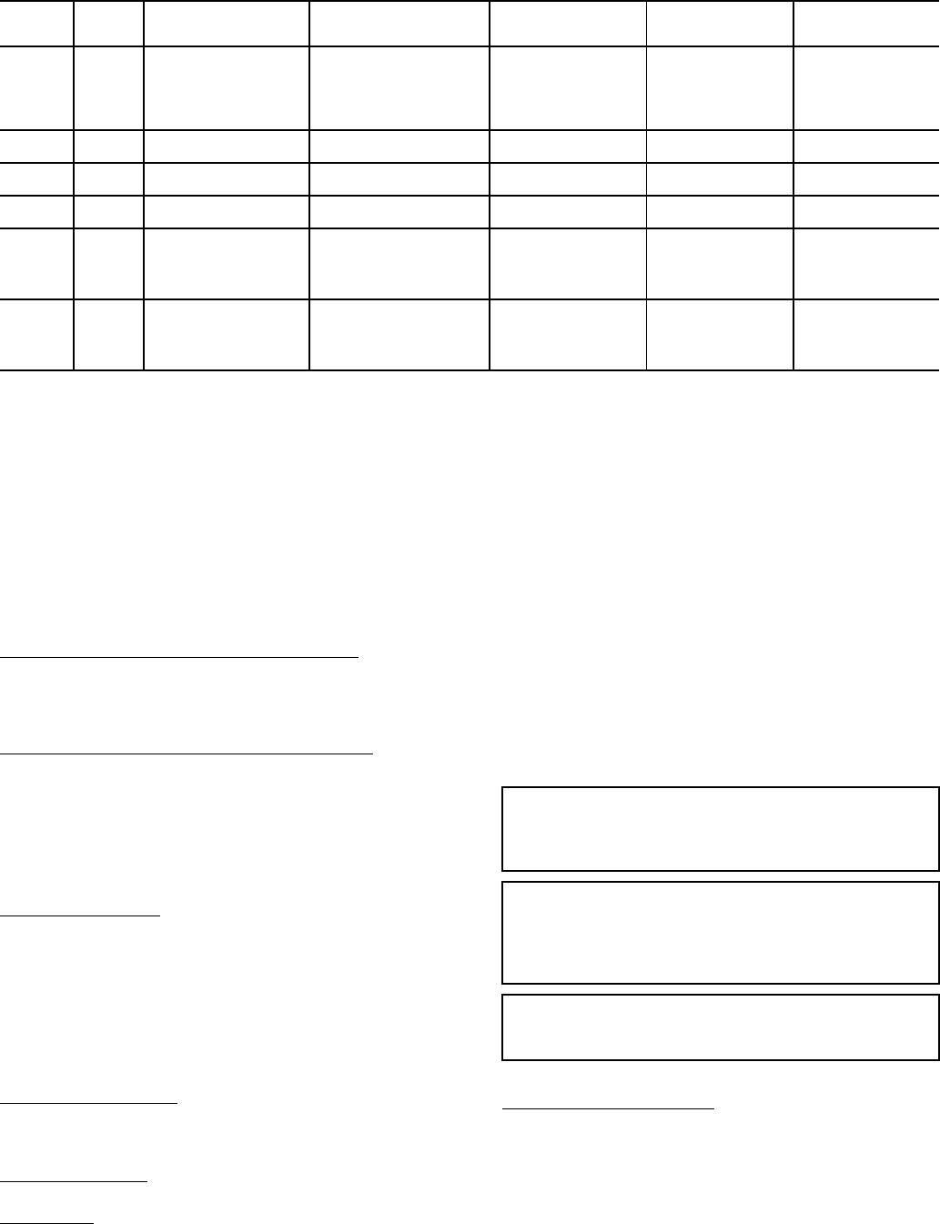
50
Table 38 — Alarm and Alert Codes (cont)
LEGEND
COMPRESSOR FAILURE ALERTS
A048 (Circuit A Compressor Availability Alarm) — This
alarm occurs when two compressors are unavailable to run on
a 3 compressor circuit. The control ensures proper oil return by
ensuring a circuit does not operate with one compressor for
longer than one hour of cumulative run time.
T051, T052, T053 (Circuit A Compresser Failures) — Alert
codes 051, 052, and 053 are for compressors A1, A2, and A3
respectively. These alerts occur when the current sensor (CS)
does not detect compressor current during compressor opera-
tion. When this occurs, the control turns off the compressor.
If the current sensor board reads OFF while the compressor
relay has been commanded ON, an alert is generated.
POSSIBLE CAUSES
Compressor Overload — Either the compressor internal over-
load protector is open or the external overload protector (Kri-
wan module) has activated. The external overload protector
modules are mounted in the compressor wiring junction box.
Temperature sensors embedded in the compressor motor wind-
ings are the inputs to the module. The module is powered with
24 vac from the units main control box. The module output is a
normally closed contact that is wired in series with the com-
pressor contactor coil. In a compressor motor overload condi-
tion, contact opens, deenergizing the compressor contactor.
Low Refrigerant Charge — If the compressor operates for an
extended period of time with low refrigerant charge, the com-
pressor ASTP device will open, which will cause the compres-
sor to trip on its overload protection device.
Circuit Breaker Trip — The compressors are protected from
short circuit by a breaker in the control box.
Wiring Error — A wiring error might not allow the compres-
sor to start.
To check out alerts T051-T053:
1. Turn on the compressor in question using Service Test
mode. If the compressor does not start, then most likely
the problem is one of the following: HPS open, open in-
ternal protection, circuit breaker trip, incorrect safety wir-
ing, or incorrect compressor wiring.
2. If the compressor does start, verify it is rotating in the cor-
rect direction.
COMPRESSOR STUCK ON FAILURE ALARMS
Circuit A A051, A052, A053 — Alarm codes 051, 052, and
053 are for compressors A1, A2, and A3. These alarms occur
when the CSB detects current when the compressor should be
off. When this occurs, the control turns off the compressor.
If the current sensor board reads ON while the compressor
relay has been commanded OFF for a period of 4 continuous
seconds, an alarm is generated. These alarms are only moni-
tored for a period of 10 seconds after the compressor relay has
ALARM/
ALERT
CODE
ALARM
OR
ALERT
DESCRIPTION
WHY WAS THIS
ALARM
GENERATED?
ACTION TAKEN
BY CONTROL
RESET
METHOD
PROBABLE
CAUSE
T302 Alert
Strainer Blowdown
Scheduled
Maintenance Due
Strainer Service
Countdown (S.T.DN)
expired. Complete strainer
blowdown and enter 'YES'
for Strainer Maintenance
Done (S.T.MN) item.
None Automatic
Routine strainer
maintenance
required
T500 Alert Current Sensor Board
A1 Failure
Alert occurs when CSB out-
put is a constant high value
Compressor A1 shut
down Automatic CSB failure.
T501 Alert Current Sensor Board
A2 Failure
Alert occurs when CSB out-
put is a constant high value
Compressor A2 shut
down Automatic CSB failure.
T502 Alert Current Sensor Board
A3 Failure
Alert occurs when CSB out-
put is a constant high value
Compressor A3 shut
down Automatic CSB failure.
T950 Alert Loss of Communication
with Water System
Manager
No communications have
been received by the MBB
within 5 minutes of last
transmission
WSM forces removed.
Chiller runs under own
control
Automatic Failed module, wiring
error, failed
transformer, loose
connection plug,
wrong address
T951 Alert Loss of Communication
with Chillervisor System
Manager
No communications have
been received by the MBB
within 5 minutes of last
transmission
CSM forces removed.
Chiller runs under own
control
Automatic Failed module, wiring
error, failed
transformer, loose
connection plug,
wrong address
CCN — Carrier Comfort Network
CSB — Current Sensor Board
CSM — Chiller System Manager
CXB — Compressor Expansion Board
EEPROM — Electronic Eraseable Programmable Read Only Memory
EMM — Energy Management Module
EWT — Entering Fluid Temperature
EXV — Electronic Expansion Valve
HSM — Hydronic System Manager
LCW — Leaving Chilled Water
LWT — Leaving Fluid Temperature
MBB — Main Base Board
OAT — Outdoor-Air Temperature
RGT — Return Gas Thermistor
WSM — Water System Manager
IMPORTANT: Prolonged operation in the wrong direction
can damage the compressor. Correct rotation can be veri-
fied by a gage set and looking for a differential pressure
rise on start-up.
IMPORTANT: If the CS is always detecting current, verify
that the compressor is on. If the compressor is on, check
the contactor and the relay on the MBB. If the compressor
is off and there is no current, verify the CSB wiring and
replace if necessary.
IMPORTANT: Return to Normal mode and observe com-
pressor operation to verify that compressor current sensor
is working.

51
been commanded OFF. This is done to facilitate a service tech-
nician forcing a relay to test a compressor.
In addition, if a compressor stuck failure occurs and the cur-
rent sensor board reports the compressor and the request off,
certain diagnostics will take place as follows:
1. If any of the compressors are diagnosed as stuck on and
the current sensor board is on and the request is off, the
control will command the condenser fans to maintain
normal head pressure.
2. The control will shut-off all other compressors.
The possible causes include welded contactor or frozen
compressor relay on the MBB.
To check out alarms A051 to A053:
1. Place the unit in Service Test mode. All compressors
should be off.
2. Verify that there is not 24-v at the contactor coil. If there
is 24 v at the contactor, check relay on MBB and wiring.
3. Check for welded contactor.
4. Verify CSB wiring.
5. Return to Normal mode and observe compressor opera-
tion to verify that compressor current sensor is working
and condenser fans are energized.
A060 (Cooler Leaving Fluid Thermistor Failure) — The
sensor reading is outside the range of –40 to 245 F (–40 to
118 C) then the alarm will occur. The cause of the alarm is usu-
ally a faulty thermistor, a shorted or open thermistor caused by
a wiring error, or a loose connection. Failure of this thermistor
will shut down the entire unit.
A061 (Cooler Entering Thermistor Failure) — If the sensor
reading is outside the range of –40 to 240 F (–40 to116 C) then
the alarm will occur. The cause of the alarm is usually a faulty
thermistor, a shorted or open thermistor caused by a wiring er-
ror, or a loose connection. Failure of this thermistor will shut
down the entire unit.
T062 (Condenser Leaving Fluid Thermistor Failure) — The
sensor reading is outside the range of –40 to 245 F (–40 to
118 C) then the alert will occur. The cause of the alert is usually
a faulty thermistor, a shorted or open thermistor caused by a
wiring error, or a loose connection. Failure of this thermistor
will send out an alert only.
T063 (Condenser Entering Thermistor Failure) — If the sen-
sor reading is outside the range of –40 to 240 F (–40 to116 C)
then the alert will occur. The cause of the alert is usually a
faulty thermistor, a shorted or open thermistor caused by a wir-
ing error, or a loose connection.Failure of this thermistor will
send out an alert only.
T068 (Circuit A Compressor Return Gas Temperature
Thermistor Failure) — This alert occurs if the RGT is config-
ured and the compressor return gas temperature sensor is out-
side the range of –40 to 240 F (–40 to 116 C). Failure of this
thermistor will shut down the appropriate circuit.
T073 (Outside Air Temperature Thermistor Failure) — This
alert occurs when the outside air temperature sensor is outside
the range of –40 to 240 F (–40 to 116 C). Failure of this therm-
istor will disable any elements of the control which requires its
use. The OAT must be configured.
T074 (Space Temperature Thermistor Failure) — This alert
occurs when the space temperature sensor is outside the range
of –40 to 245 F (–40 to 118 C). Failure of this thermistor will
disable any elements of the control which requires its use. The
cause of the alert is usually a faulty thermistor in the T55, or
T58 device, a shorted or open thermistor caused by a wiring er-
ror, or a loose connection. The SPT must be configured.
A077 (Circuit Saturated Suction Temperature Exceeds
Cooler Leaving Water Temperature) — This alarm occurs
when the saturated suction temperature (SST) is greater than
leaving water for 5 minutes. This alarm will occur if either the
suction pressure transducer reading, which is used to calculate
SST, or cooler leaving water is incorrect. Potential causes for
this alarm are loose wiring connection, sensor not located in
well or bad Schrader fitting. Reset is manual.
T079 (Dual Chiller Thermistor Failure) — This alert occurs
when the dual chiller temperature sensor is outside its range of
–40 to 240 F. Failure of this thermistor will disable Dual Chill-
er operation and return to stand-alone operation. The unit must
be configured for Dual Chiller operation for this alert to occur.
The cause of the alert is usually a faulty thermistor, a shorted or
open thermistor caused by a wiring error, or a loose connection.
Reset is automatic.
A090 (Circuit A Discharge Pressure Transducer Failure) —
This alarm occurs when the pressure is outside the range of 0.0
to 667.0 psig. A circuit cannot run when this alarm is active.
Use the scrolling marquee to reset the alarm. The cause of the
alarm is usually a faulty transducer, faulty 5-v power supply, or
a loose connection.
A092 (Circuit A Suction Pressure Transducer Failure) —
This alarm occurs when the pressure is outside the range of 0.0
to 420.0 psig. A circuit cannot run when this alarm is active.
Use the scrolling marquee to reset the alarm. The cause of the
alarm is usually a faulty transducer, faulty 5-v power supply, or
a loose connection.
T094 (Discharge Gas Thermistor Failure) — This alert oc-
curs for units which have the digital compressor installed on
circuit A. If discharge gas temperature is open or shorted, the
circuit will be shut off. The alert will reset itself when discharge
temperature is less than 250 F (121.1 C). The cause of the alert
is usually low refrigerant charge or a faulty thermistor.
A110 (Circuit A Loss of Charge) — This alarm occurs when
the compressor is OFF and the discharge pressure is less than
26 psig.
A112 (Circuit A High Saturated Suction Temperature) —
Alarm code 112 occurs when compressors in a circuit have
been running for at least 5 minutes and the circuit saturated
suction temperature is greater than 70 F (21.1 C). The high sat-
urated suction alarm is generated and the circuit is shut down.
A114 (Circuit A Low Superheat) — Alarm code 114 occurs
when the superheat of a circuit is less than 5 F (2.8 C) for 5
continuous minutes. The low superheat alarm is generated and
the circuit is shut down. The RGT sensor must be installed.
A122 (Circuit A, High Pressure Switch Failure) — The
high pressure switch is wired in series with the compressor
contactor coils of each compressor on the circuit to disable
compressor operation immediately upon a high discharge pres-
sure condition. The normally closed contacts in the switches
are calibrated to open at 650 ± 10 psig which corresponds to a
saturated condensing temperature of 155.6 ± 1.3 F. The pres-
sure switches will automatically reset when the discharge pres-
sure is reduced to 500 ± 15 psig which corresponds to a saturat-
ed condensing temperature of 134.1 ± 2.4 F.
The output of the high pressure switch is wired to inputs on
the MBB to provide the control with an indication of a high
pressure switch trip. This alert could occur when compressors
are off if the wiring to the switch is broken or the switch has
failed open.
If the high pressure switch trips on a circuit with compres-
sors commanded on, the discharge pressure is recorded. If the
recorded discharge pressure is between 630 to 660 psig (satu-
rated condensing temperature between 153.0 and 156.9 F), and
is also less than the value recorded on any previous high pres-
sure switch trip, the upper horizontal portion of the compressor
operating envelope (see Fig. 12) is lowered 0.4 F (3 psig). The
control will not allow the compressor operating envelope to be
lowered below 153.0 F (630 psig).

52
This is done to make a rough calibration of the high pres-
sure switch trip point. In most cases this allows the control to
detect a high head pressure condition prior to reaching the high
pressure switch trip point.
When the trip occurs, all mechanical cooling on the circuit
is shut down for 15 minutes. After 15 minutes, the circuit is al-
lowed to restart.
A126 (Circuit A High Head Pressure) — This alarm occurs
when the appropriate saturated condensing temperature is
greater than the operating envelope shown in Fig 12. Prior to
the alarm, the control will shut down one compressor on a cir-
cuit if that circuit's saturated condensing temperature is greater
than the maximum SCT minus 5° F (2.7° C). If SCT continues
to rise to greater than the maximum SCT, the alarm will occur
and the circuit's remaining compressor will shut down. The
cause of the alarm is usually an overcharged system, high out-
door ambient temperature coupled with dirty outdoor coil
(30MPA only), plugged filter drier, a faulty high-pressure
switch, or loss of condenser water flow.
A140 (Reverse Rotation Detected) — A test is made once, on
power up, for suction pressure change on the first activated cir-
cuit. The unit control determines failure as follows:
1. The suction pressure is sampled 5 seconds before the
compressor is brought on, right when the compressor is
brought on and 5 seconds afterwards.
2. The rate of suction pressure change from 5 seconds be-
fore the compressor is brought on to when the compres-
sor is brought on is calculated.
3. The rate of suction pressure change from when the
compressor is brought on to 5 seconds afterwards is
calculated.
4. With the above information, the test for reverse rotation is
made. If the suction pressure change 5 seconds after com-
pression is greater than the suction pressure change 5 sec-
onds before compression – 1.25, then there is a reverse
rotation error.
This alarm will disable mechanical cooling and will require
manual reset. This alarm may be disabled once the reverse ro-
tation check has been verified by setting REV.R = Yes.
A150 (Unit is in Emergency Stop) — If the CCN emergency
stop command is received, the alarm is generated and the unit
will be immediately stopped.
If the CCN point name "EMSTOP" in the system table is set
to emergency stop, the unit will shut down immediately and
broadcast an alarm back to the CCN, indicating that the unit is
down. This alarm will clear when the variable is set back to
"enable."
A151 (Illegal Configuration) — An A151 alarm indicates an
invalid configuration has been entered. The following are ille-
gal configurations.
• Invalid unit size has been entered.
• Unit configuration set to invalid type.
A152 (Unit Down Due to Failure) — Reset is automatic
when all alarms are cleared. This alarm indicates the unit is at
0% capacity.
T153 (Real Time Clock Hardware Failure) — A problem
has been detected with MBB real time clock hardware. Try re-
setting the power and check the indicator lights. If the alarm
continues, the board should be replaced.
A154 (Serial EEPROM Hardware Failure) — A problem
has been detected with the EEPROM on the MBB. Try
resetting the power and check the indicator lights. If the alarm
continues, the board should be replaced.
T155 (Serial EEPROM Storage Failure Error) — A problem
has been detected with the EEPROM storage on the MBB. Try
resetting the power and check the indicator lights. If the alert
continues, the board should be replaced.
A156 (Critical Serial EEPROM Storage Failure Error) — A
problem has been detected with the EEPROM storage on the
MBB. Try resetting the power and check the indicator lights. If
the alarm continues, the board should be replaced.
A157 (A/D Hardware Failure) — A problem has been detect-
ed with A/D conversion on the boards. Try resetting the power
and check the indicator lights. If the alarm continues, the board
should be replaced.
T173 (Energy Management Module Communication Fail-
ure) — This alert indicates that there are communications
problems with the energy management. All functions per-
formed by the EMM will stop, which can include demand lim-
it, reset and capacity input. The alert will automatically reset.
T174 (4 to 20 mA Cooling Set point Input Failure) — This
alert indicates a problem has been detected with cooling set
point 4 to 20 mA input. The input value is either less than 2 mA
or greater than 22 mA.
T176 (4 to 20 mA Reset Input Failure) — This alert indi-
cates a problem has been detected with reset 4 to 20 mA input.
The input value is either less than 2 mA or greater than 22 mA.
The reset function will be disabled when this occurs.
T177 (4 to 20 mA Demand Limit Input Failure) — This
alert indicates a problem has been detected with demand limit
4 to 20 mA input. The input value is either less than 2 mA or
greater than 22 mA. The reset function will be disabled when
this occurs.
T500, T501, T502 (Current Sensor Board Failure — A xx
Circuit A — Alert codes 500, 501, and 502 are for compres-
sors A1, A2, and A3 respectively. These alerts occur when the
output of the CSB is a constant high value. These alerts reset
automatically. If the problem cannot be resolved, the CSB must
be replaced.

53
APPENDIX A — LOCAL DISPLAY TABLES
Run Status Mode and Sub-Mode Directory
SUB-MODE ITEM DISPLAY ITEM DESCRIPTION CCN POINT COMMENT
VIEW
AUTO VIEW OF RUN STATUS
EWT xxx.x ºF Entering Fluid Temp EWT
LWT xxx.x ºF Leaving Fluid Temp LWT
SETP xxx.x ºF Active Setpoint SP
CTPT xxx.x ºF Control Point CTRL_PNT
LOD.F xxx Load/Unload Factor SMZ
STAT Control Mode STAT
OCC NO/YES Occupied OCC
MODE NO/YES Override Modes in
Effect MODE
CAP xxx Percent Total Capacity CAP_T
STGE x Requested Stage STAGE
ALRM xxx Current Alarms & Alerts ALRMALRT
TIME xx.xx Time of Day TIMECOPY 00:00-23:59
MNTH xx Month of Year MOY 1 - 12 (1 = January,
2 = February, etc.)
DATE xx Day of Month DOM 01-31
YEAR xx Year of Century YOCDISP
RUN
UNIT RUN HOUR AND START
HRS.U xxxx HRS Machine Operating
Hours HR_MACH 0 to 999999
STR.U xxxx Machine Starts CY_MACH 0 to 1000000
HR.P1 xxxx HRS Cooler Pump Run
Hours HR_CPUMP 0 to 999999.9
HR.P2 xxxx HRS Condenser Pump Run
Hours HR_DPUMP 0 to 999999.9
HOUR
CIRC AND COMP RUN HOURS
HR.A1 xxxx HRS Compressor A1 Run
Hours HOURS_A1 0 to 999999
HR.A2 xxxx HRS Compressor A2 Run
Hours HOURS_A2 0 to 999999
HR.A3 xxxx HRS Compressor A3 Run
Hours HOURS_A3 0 to 999999
STRT
COMPRESSOR STARTS
ST.A1 xxxx Compressor A1 Starts CY_A1 0 to 999999
ST.A2 xxxx Compressor A2 Starts CY_A2 0 to 999999
ST.A3 xxxx Compressor A3 Starts CY_A3 0 to 999999
PM
PREVENTIVE MAINTENANCE
STRN STRAINER MAINTENANCE
SI.ST xxxx HRS Strainer Srvc Interval SI_STRNR 0 to 65535
S.T.DN xxxx HRS Strainer Srvc Count-
down ST_CDOWN 0 to 65535
S.T.MN NO/YES Strainer Maint. Done ST_MAINT
ST.DT STRAINER MAINT. DATES
S.T.M0 MM/DD/YY HH:MM
S.T.M1 MM/DD/YY HH:MM
S.T.M2 MM/DD/YY HH:MM
S.T.M3 MM/DD/YY HH:MM
S.T.M4 MM/DD/YY HH:MM
VERS
SOFTWARE VERSION NUMBERS
AUX CESR131333-xx-xx
MBB CESR131279-xx-xx
EMM CESR131174-xx-xx
MARQ CESR131171-xx-xx
NAVI CESR130227-xx-xx
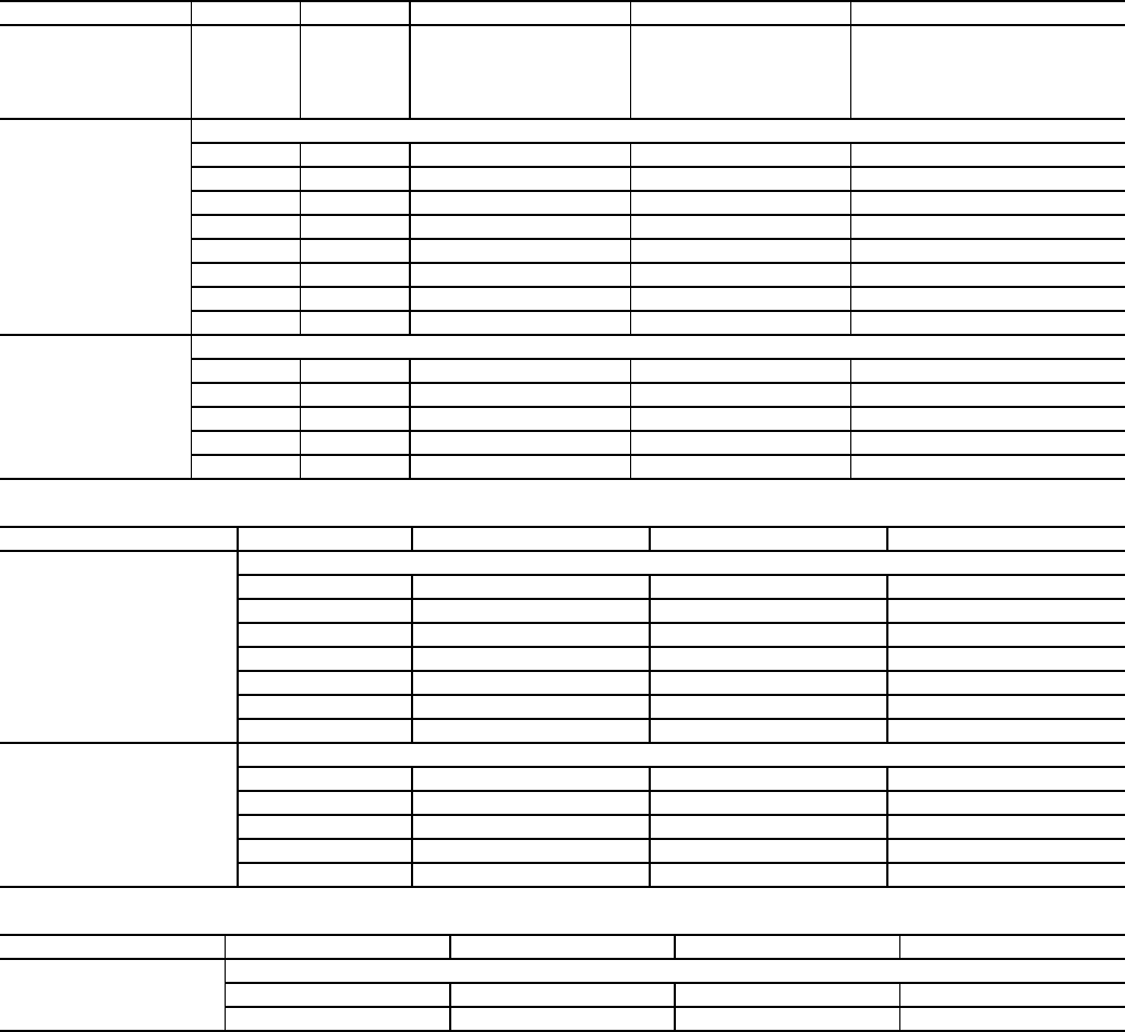
54
APPENDIX A — LOCAL DISPLAY TABLES (cont)
Service Test Mode and Sub-Mode Directory
Temperature Mode and Sub-Mode Directory
Pressures Mode and Sub-Mode Directory
SUB-MODE ITEM DISPLAY ITEM DESCRIPTION CCN POINT COMMENT
TEST ON/OFF Service Test Mode MAN_CTRL
To enable Service Test mode, move
Enable/Off/Remote contact switch
to
OFF. Change TEST to ON.
Move switch to ENABLE
OUTS
OUTPUTS AND PUMPS
CLR.P OFF/ON Cooler Pump Relay S_CLPMP
CND.P OFF/ON Condenser Pump S_CNDPMP
UL.TM xx Comp A1 Unload Time S_A1ULTM 0 to 15
CC.H OFF/ON Crankcase Heater S_CCH
CW.VO OFF/ON Condenser Valve Open S_CWVO
CW.VC OFF/ON Condenser Valve Close S_CWVC
LL.SV OFF/ON Liquid Line Solenoid S_LLSV
RMT.A OFF/ON Remote Alarm Relay S_ALM
CMPA
CIRCUIT A COMPRESSOR TST
CC.A1 OFF/ON Compressor A1 Relay S_A1_RLY
UL.TM xx Comp A1 Unload Time S_A1ULTM 0 to 15
CC.A2 OFF/ON Compressor A2 Relay S_A2_RLY
CC.A3 OFF/ON Compressor A3 Relay S_A3_RLY
MLV OFF/ON Minimum Load Valve Relay S_MLV
SUB-MODE ITEM DISPLAY ITEM DESCRIPTION CCN POINT
UNIT
ENT AND LEAVE UNIT TEMPS
CEWT xxx.x °F Cooler Entering Fluid COOL_EWT
CLWT xxx.x °F Cooler Leaving Fluid COOL_LWT
CDET xxx.x °F Condenser Entering Fluid COND_EWT
CDLT xxx.x °F Condenser Leaving Fluid COND_LWT
OAT xxx.x °F Outside Air Temperature OAT
SPT xxx.x °F Space Temperature SPT
DLWT xxx.x °F Lead/Lag Leaving Fluid DUAL_LWT
CIR.A
TEMPERATURES CIRCUIT A
SCT.A xxx.x °F Saturated Condensing Tmp TMP_SCTA
SST.A xxx.x °F Saturated Suction Temp TMP_SSTA
RGT.A xxx.x °F Compr Return Gas Temp TMP_RGTA
D.GAS xxx.x °F Discharge Gas Temp DISGAS
SH.A xxx.x ΔF Suction Superheat Temp SH_A
SUB-MODE ITEM DISPLAY ITEM DESCRIPTION CCN POINT
PRC.A
PRESSURES CIRCUIT A
DP.A xxx.x PSIG Discharge Pressure DP_A
SP.A xxx.x PSIG Suction Pressure SP_A

55
APPENDIX A — LOCAL DISPLAY TABLES (cont)
Set Points Mode and Sub-Mode Directory
Inputs Mode and Sub-Mode Directory
Outputs Mode and Sub-Mode Directory
SUB-MODE ITEM DISPLAY ITEM DESCRIPTION RANGE CCN POINT
COOL
COOLING SETPOINTS
CSP.1 xxx.x °F Cooling Setpoint 1 –20 to 70 CSP1
CSP.2 xxx.x °F Cooling Setpoint 2 –20 to 70 CSP2
CSP.3 xxx.x °F ICE Setpoint –20 to 32 CSP3
HEAD HEAD PRESSURE SETPOINTS
H.DP xxx.x °F Head Setpoint 85 to 120 HSP
FRZ BRINE FREEZE SETPOINT
BR.FZ xx.x °F Brine Freeze Point –20 to 34 BRN_FRZ
SUB-MODE ITEM DISPLAY ITEM DESCRIPTION CCN POINT
GEN.I
GENERAL INPUTS
STST OFF/ON Start/Stop Switch START
FLOW OFF/ON Cooler Flow Switch COOLFLOW
CD.FL OFF/ON Condenser Flow Switch CONDFLOW
DLS1 OFF/ON Demand Limit Switch 1 DMD_SW1
DLS2 OFF/ON Demand Limit Switch 2 DMD_SW2
ICED OFF/ON Ice Done ICE_DONE
DUAL OFF/ON Dual Setpoint Switch DUAL_IN
CRCT
CIRCUIT INPUTS
FKA1 OFF/ON Compressor A1 Feedback K_A1_FBK
FKA2 OFF/ON Compressor A2 Feedback K_A2_FBK
FKA3 OFF/ON Compressor A3 Feedback K_A3_FBK
HPS.A OFF/ON High Pressure Switch A HPSA
4-20
4-20 MA INPUTS
DMND xx.x 4-20 ma Demand Signal LMT_MA
RSET xx.x 4-20 ma Reset Signal RST_MA
CSP xx.x 4-20 ma Cooling Setpoint CSP_IN
SUB-MODE ITEM DISPLAY ITEM DESCRIPTION CCN POINT
GEN.O
GENERAL OUTPUTS
C.LWP OFF/ON Cooler Pump Relay COOLPUMP
C.DWP OFF/ON Condenser Pump CONDPUMP
ALRM OFF/ON Alarm State ALM
CDWO OFF/ON Condenser Valve Open COND_WVO
CDWC OFF/ON Condenser Valve Close COND_WVC
CIR.A
OUTPUTS CIRCUIT A
CC.A1 OFF/ON Compressor A1 Relay K_A1_RLY
D.SOL OFF/ON Digital Scroll Solenoid DISCRSOL
CC.A2 OFF/ON Compressor A2 Relay K_A2_RLY
CC.A3 OFF/ON Compressor A3 Relay K_A3_RLY
CCH OFF/ON Crankcase Heater Relay CCH_RLY
LLSV OFF/ON Liquid Line Solenoid LLSV_A
MLV.R OFF/ON Minimum Load Valve Relay MLV_RLY
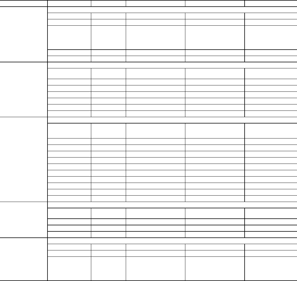
56
APPENDIX A — LOCAL DISPLAY TABLES (cont)
Configuration Mode and Sub-Mode Directory
SUB-MODE ITEM DISPLAY ITEM DESCRIPTION CCN POINT COMMENT
DISP
DISPLAY CONFIGURATION
TEST OFF/ON Test Display LEDs DISPTEST
METR OFF/ON Metric Display DISPUNIT Off = English On = Metric
LANG X Language Selection LANGUAGE
Default: 0
0 = English
1 = Espanol
2 = Francais
3 = Portuguese
PAS.E DSBL/ENBL Password Enable PASS_EBL
PASS XXXX Service Password PASSCOPY 0 to 9999
UNIT
UNIT CONFIGURATION
TYPE XUnit Type UNIT_TYP 2=Water Cooled, 3=Split
System
SIZE XXX Unit Size SIZE 10 to 100
SZA.1 XX Compressor A1 Size SIZE_A1
SZA.2 XX Compressor A2 Size SIZE_A2
SZA.3 XX Compressor A3 Size SIZE_A3
A1.TY NO/YES Compressor A1 Digital? CPA1TYPE
MAX.T XX Maximum A1 Unload Time MAXULTME 0 to 15
OPT1
UNIT OPTIONS 1 HARDWARE
FLUD X Cooler Fluid 1 = Water
2 = Medium Temperature
Brine
FLUIDTYP
MLV.S NO/YES Minimum Load Vlv Select MLV_FLG
RG.EN DSBL/ENBL Return Gas Sensor Enable RGT_ENA
OAT.E DSBL/ENBL Enable OAT Sensor OAT_ENA
D.G.EN DSBL/ENBL Dischrge Gas Temp Enable DISGASEN
CSB.E DSBL/ENBL CSB Boards Enable CSB_ENA
CPC OFF/ON Cooler Pump Control CPC
PM.DY XX MIN Cooler Pump Shutdown Dly PUMP_DLY 0 to 10
DPME XEnable Condenser Pump CONDPMPE 0 to 2
DFLS DSBL/ENBL Enable Cond Flow Switch CONDFLSW
CDWS DSBL/ENBL Enable Cond Wtr Sensors CONDWTRS
OPT2
UNIT OPTIONS 2 CONTROLS
CTRL X Control Method CONTROL 0=Switch, 1=Occupancy,
2=Occupancy, 3=CCN
LCWT XX High LCW Alert Limit LCW_LMT 2 to 60
DELY XX Minutes Off Time DELAY 0 to 15
ICE.M DSBL/ENBL Ice Mode Enable ICE_CNFG
CCN
CCN NETWORK CONFIGS
CCNA XXX CCN Address CCNADD 1 to 239
CCNB XXX CCN Bus Number CCNBUS 0 to 239
BAUD X CCN Baud Rate CCNBAUDD
1 = 2400
2 = 4800
3 = 9600
4 =19,200
5 =38,400
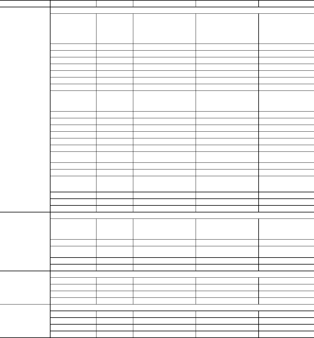
57
APPENDIX A — LOCAL DISPLAY TABLES (cont)
Configuration Mode and Sub-Mode Directory (cont)
SUB-MODE ITEM DISPLAY ITEM DESCRIPTION CCN POINT COMMENT
RSET
RESET COOL TEMP
CRST X Cooling Reset Type CRST_TYP
0 = No Reset
1 = 4 to 20 mA Input
2 = Outdoor Air Tempera-
ture
3 = Return Fluid
4 = Space Temperature
MA.DG XX.XΔF4-20 - Degrees Reset 420_DEG -30 to 30
RM.NO XXX.X °F Remote - No Reset Temp REM_NO 0 to125
RM.F XXX.X °F Remote - Full Reset Temp REM_FULL 0 to125
RM.DG XX.X °F Remote - Degrees Reset REM_DEG -30 to 30
RT.NO XXX.XΔFReturn - No Reset Temp RTN_NO 0 to 30
RT.F XXX.XΔFReturn - Full Reset Temp RTN_FULL 0 to 10
RT.DG XX.X °F Return - Degrees Reset RTN_DEG -30 to 30
DMDC X Demand Limit Select DMD_CTRL
0 = None
1 = Switch
2 - 4 to 20 mA Input
3 = CCN Loadshed
DM20 XXX% Demand Limit at 20 mA DMT20MA 0 to 100
SHNM XXX Loadshed Group Number SHED_NUM 0 to 99
SHDL XXX% Loadshed Demand Delta SHED_DEL 0 to 60
SHTM XXX Maximum Loadshed Time SHED_TIM 0 to 120
DLS1 XXX% Demand Limit Switch 1 DLSWSP1 0 to 100
DLS2 XXX% Demand Limit Switch 2 DLSWSP2 0 to 100
LLEN DSBL/ENBL Lead/Lag Chiller Enable LL_ENA
MSSL SLVE/MAST Master/Slave Select MS_SEL
SLVA XXX Slave Address SLV_ADDR 0 to 239
LLBL X Lead/Lag Balance Select LL_BAL
0 = Master Leads
1 = Slave Leads
2 = Automatic
LLBD XXX Lead/Lag Balance Delta LL_BAL_D 40 to 400 hours
LLDY XXX Lag Start Delay LL_DELAY 0 to 30 minutes
PAR A NO/YES Parallel Configuration PARALLEL
SLCT
SETPOINT AND RAMP LOAD
CLSP X Cooling Set Point Select CLSP_TYP
0 = Single
1 = Dual Switch
2 = Dual CCN Occupied
3 = 4 to 20 mA Input
RL.S DSBL/ENBL Ramp Load Select RAMP_EBL
CRMP X.X Cooling Ramp Loading CRAMP 0.2 to 2
SCHD XX Schedule Number SCHEDNUM 0 to 99
Z.GN X.X Deadband Multiplier Z_GAIN 1 to 4
SERV
SERVICE CONFIGURATION
EN.A1 DSBL/ENBL Enable Compressor A1 ENABLEA1
EN.A2 DSBL/ENBL Enable Compressor A2 ENABLEA2
EN.A3 DSBL/ENBL Enable Compressor A3 ENABLEA3
REV.R DSBL/ENBL Reverse Rotation Enable REVR_ENA
BCST
BROADCAST CONFIGURATION
T.D.BC OFF/ON CCN Time/Date Broadcast CCNBC
OAT.B OFF/ON CCN OAT Broadcast OATBC
G.S.BC OFF/ON Global Schedule Broadcst GSBC
BC.AK OFF/ON CCN Broadcast Ack'er CCNBCACK

58
APPENDIX A — LOCAL DISPLAY TABLES (cont)
Time Clock Mode and Sub-Mode Directory
SUB-MODE ITEM DISPLAY ITEM DESCRIPTION CCN POINT COMMENT
TIME TIME OF DAY
HH.MM XX.XX Hour and Minute TIME
DATE
MONTH, DATE, DAY, AND YEAR
MNTH XX Month of Year MOY 1 to 12 (1 = January,
2 = February, etc.)
DOM XX Day of Month DOM 1 to 31
DAY X Day of Week DOWDISP 1 - 7 (1 = Sunday,
2 = Monday, etc.)
YEAR XXXX Year of Century YOCDISP 1999 to 2098
DST
DAYLIGHT SAVINGS TIME
STR.M XX Month STARTM Default: 4 Range 1 to 12
STR.W X Week STARTW Default: 1 Range 1 to 5
STR.D X Day STARTD Default: 7 Range 1 to 7
MIN.A XX Minutes to Add MINADD Default: 60 Range 0 to
90
STP.M XX Month STOPM Default: 10 Range 1 to
12
STP.W XX Week STOPW Default: 5 Range 1to 5
STP.D XX Day STOPD Default: 7 Range 1 to 7
MIN.S XX Minutes to Subtract MINSUB Default: 60 Range 0 to
90
HOL.L LOCAL HOLIDAY SCHEDULES
HD.01
HOLIDAY SCHEDULE 01
MON XX Holiday Start Month HOLMON01 0 to 12
DAY XX Start Day HOLDAY01 0 to 31
LEN XX Duration (days) HOLLEN01 0 to 99
HD.02
HOLIDAY SCHEDULE 02
MON XX Holiday Start Month HOLMON02 0 to 12
DAY XX Start Day HOLDAY02 0 to 31
LEN XX Duration (days) HOLLEN02 0 to 99
HD.03
HOLIDAY SCHEDULE 03
MON XX Holiday Start Month HOLMON03 0 to 12
DAY XX Start Day HOLDAY03 0 to 31
LEN XX Duration (days) HOLLEN03 0 to 99
HD.04
HOLIDAY SCHEDULE 04
MON XX Holiday Start Month HOLMON04 0 to 12
DAY XX Start Day HOLDAY04 0 to 31
LEN XX Duration (days) HOLLEN04 0 to 99
HD.05
HOLIDAY SCHEDULE 05
MON XX Holiday Start Month HOLMON05 0 to 12
DAY XX Start Day HOLDAY05 0 to 31
LEN XX Duration (days) HOLLEN05 0 to 99
HD.06
HOLIDAY SCHEDULE 06
MON XX Holiday Start Month HOLMON06 0 to 12
DAY XX Start Day HOLDAY06 0 to 31
LEN XX Duration (days) HOLLEN06 0 to 99
HD.07
HOLIDAY SCHEDULE 07
MON XX Holiday Start Month HOLMON07 0 to 12
DAY XX Start Day HOLDAY07 0 to 31
LEN XX Duration (days) HOLLEN07 0 to 99
HD.08
HOLIDAY SCHEDULE 08
MON XX Holiday Start Month HOLMON08 0 to 12
DAY XX Start Day HOLDAY08 0 to 31
LEN XX Duration (days) HOLLEN08 0 to 99

59
APPENDIX A — LOCAL DISPLAY TABLES (cont)
Time Clock Mode and Sub-Mode Directory (cont)
SUB-MODE ITEM DISPLAY ITEM DESCRIPTION CCN POINT COMMENT
HD.09
HOLIDAY SCHEDULE 09
MON XX Holiday Start Month HOLMON09 0 to 12
DAY XX Start Day HOLDAY09 0 to 31
LEN XX Duration (days) HOLLEN09 0 to 99
HD.10
HOLIDAY SCHEDULE 10
MON XX Holiday Start Month HOLMON10 0 to 12
DAY XX Start Day HOLDAY10 0 to 31
LEN XX Duration (days) HOLLEN10 0 to 99
HD.11
HOLIDAY SCHEDULE 11
MON XX Holiday Start Month HOLMON11 0 to 12
DAY XX Start Day HOLDAY11 0 to 31
LEN XX Duration (days) HOLLEN11 0 to 99
HD.12
HOLIDAY SCHEDULE 12
MON XX Holiday Start Month HOLMON12 0 to 12
DAY XX Start Day HOLDAY12 0 to 31
LEN XX Duration (days) HOLLEN12 0 to 99
HD.13
HOLIDAY SCHEDULE 13
MON XX Holiday Start Month HOLMON13 0 to 12
DAY XX Start Day HOLDAY13 0 to 31
LEN XX Duration (days) HOLLEN13 0 to 99
HD.14
HOLIDAY SCHEDULE 14
MON XX Holiday Start Month HOLMON14 0 to 12
DAY XX Start Day HOLDAY14 0 to 31
LEN XX Duration (days) HOLLEN14 0 to 99
HD.15
HOLIDAY SCHEDULE 15
MON XX Holiday Start Month HOLMON15 0 to 12
DAY XX Start Day HOLDAY15 0 to 31
LEN XX Duration (days) HOLLEN15 0 to 99
HD.16
HOLIDAY SCHEDULE 16
MON XX Holiday Start Month HOLMON16 0 to 12
DAY XX Start Day HOLDAY16 0 to 31
LEN XX Duration (days) HOLLEN16 0 to 99
HD.17
HOLIDAY SCHEDULE 17
MON XX Holiday Start Month HOLMON17 0 to 12
DAY XX Start Day HOLDAY17 0 to 31
LEN XX Duration (days) HOLLEN17 0 to 99
HD.18
HOLIDAY SCHEDULE 18
MON XX Holiday Start Month HOLMON18 0 to 12
DAY XX Start Day HOLDAY18 0 to 31
LEN XX Duration (days) HOLLEN18 0 to 99
HD.19
HOLIDAY SCHEDULE 19
MON XX Holiday Start Month HOLMON19 0 to 12
DAY XX Start Day HOLDAY19 0 to 31
LEN XX Duration (days) HOLLEN19 0 to 99

60
APPENDIX A — LOCAL DISPLAY TABLES (cont)
Time Clock Mode and Sub-Mode Directory (cont)
SUB-MODE ITEM DISPLAY ITEM DESCRIPTION CCN POINT COMMENT
HD.20
HOLIDAY SCHEDULE 20
MON XX Holiday Start Month HOLMON20 0 to 12
DAY XX Start Day HOLDAY20 0 to 31
LEN XX Duration (days) HOLLEN20 0 to 99
HD.21
HOLIDAY SCHEDULE 21
MON XX Holiday Start Month HOLMON21 0 to 12
DAY XX Start Day HOLDAY21 0 to 31
LEN XX Duration (days) HOLLEN21 0 to 99
HD.22
HOLIDAY SCHEDULE 22
MON XX Holiday Start Month HOLMON22 0 to 12
DAY XX Start Day HOLDAY22 0 to 31
LEN XX Duration (days) HOLLEN22 0 to 99
HD.23
HOLIDAY SCHEDULE 23
MON XX Holiday Start Month HOLMON23 0 to 12
DAY XX Start Day HOLDAY23 0 to 31
LEN XX Duration (days) HOLLEN23 0 to 99
HD.24
HOLIDAY SCHEDULE 24
MON XX Holiday Start Month HOLMON24 0 to 12
DAY XX Start Day HOLDAY24 0 to 31
LEN XX Duration (days) HOLLEN24 0 to 99
HD.25
HOLIDAY SCHEDULE 25
MON XX Holiday Start Month HOLMON25 0 to 12
DAY XX Start Day HOLDAY25 0 to 31
LEN XX Duration (days) HOLLEN25 0 to 99
HD.26
HOLIDAY SCHEDULE 26
MON XX Holiday Start Month HOLMON26 0 to 12
DAY XX Start Day HOLDAY26 0 to 31
LEN XX Duration (days) HOLLEN26 0 to 99
HD.27
HOLIDAY SCHEDULE 27
MON XX Holiday Start Month HOLMON27 0 to 12
DAY XX Start Day HOLDAY27 0 to 31
LEN XX Duration (days) HOLLEN27 0 to 99
HD.28
HOLIDAY SCHEDULE 28
MON XX Holiday Start Month HOLMON28 0 to 12
DAY XX Start Day HOLDAY28 0 to 31
LEN XX Duration (days) HOLLEN28 0 to 99
HD.29
HOLIDAY SCHEDULE 29
MON XX Holiday Start Month HOLMON29 0 to 12
DAY XX Start Day HOLDAY29 0 to 31
LEN XX Duration (days) HOLLEN29 0 to 99
HD.30
HOLIDAY SCHEDULE 30
MON XX Holiday Start Month HOLMON30 0 to 12
DAY XX Start Day HOLDAY30 0 to 31
LEN XX Duration (days) HOLLEN30 0 to 99

61
APPENDIX A — LOCAL DISPLAY TABLES (cont)
Time Clock Mode and Sub-Mode Directory (cont)
SUB-MODE ITEM DISPLAY ITEM DESCRIPTION CCN POINT COMMENT
SCH.N Schedule Number 0 SCHEDNUM 0 to 99
SCH.L LOCAL OCCUPANCY SCHEDULE
PER.1
OCCUPANCY PERIOD 1
OCC.1 XX:XX Period Occupied Time PER1OCC
UNC.1 XX:XX Period Unoccupied
Time PER1UNC
MON.1 NO/YES Monday In Period PER1MON
TUE.1 NO/YES Tuesday In Period PER1TUE
WED.1 NO/YES Wednesday In Period PER1WED
THU.1 NO/YES Thursday In Period PER1THU
FRI.1 NO/YES Friday In Period PER1FRI
SAT.1 NO/YES Saturday In Period PER1SAT
SUN.1 NO/YES Sunday In Period PER1SUN
HOL.1 NO/YES Holiday In Period PER1HOL
PER.2
OCCUPANCY PERIOD 2
OCC.2 XX:XX Period Occupied Time PER2OCC
UNC.2 XX:XX Period Unoccupied
Time PER2UNC
MON.2 NO/YES Monday In Period PER2MON
TUE.2 NO/YES Tuesday In Period PER2TUE
WED.2 NO/YES Wednesday In Period PER2WED
THU.2 NO/YES Thursday In Period PER2THU
FRI.2 NO/YES Friday In Period PER2FRI
SAT.2 NO/YES Saturday In Period PER2SAT
SUN.2 NO/YES Sunday In Period PER2SUN
HOL.2 NO/YES Holiday In Period PER2HOL
PER.3
OCCUPANCY PERIOD 3
OCC.3 XX:XX Period Occupied Time PER3OCC
UNC.3 XX:XX Period Unoccupied
Time PER3UNC
MON.3 NO/YES Monday In Period PER3MON
TUE.3 NO/YES Tuesday In Period PER3TUE
WED.3 NO/YES Wednesday In Period PER3WED
THU.3 NO/YES Thursday In Period PER3THU
FRI.3 NO/YES Friday In Period PER3FRI
SAT.3 NO/YES Saturday In Period PER3SAT
SUN.3 NO/YES Sunday In Period PER3SUN
HOL.3 NO/YES Holiday In Period PER3HOL
PER.4
OCCUPANCY PERIOD 4
OCC.4 XX:XX Period Occupied Time PER4OCC
UNC.4 XX:XX Period Unoccupied
Time PER4UNC
MON.4 NO/YES Monday In Period PER4MON
TUE.4 NO/YES Tuesday In Period PER4TUE
WED.4 NO/YES Wednesday In Period PER4WED
THU.4 NO/YES Thursday In Period PER4THU
FRI.4 NO/YES Friday In Period PER4FRI
SAT.4 NO/YES Saturday In Period PER4SAT
SUN.4 NO/YES Sunday In Period PER4SUN
HOL.4 NO/YES Holiday In Period PER4HOL
PER.5
OCCUPANCY PERIOD 5
OCC.5 XX:XX Period Occupied Time PER5OCC
UNC.5 XX:XX Period Unoccupied
Time PER5UNC
MON.5 NO/YES Monday In Period PER5MON
TUE.5 NO/YES Tuesday In Period PER5TUE
WED.5 NO/YES Wednesday In Period PER5WED
THU.5 NO/YES Thursday In Period PER5THU
FRI.5 NO/YES Friday In Period PER5FRI
SAT.5 NO/YES Saturday In Period PER5SAT
SUN.5 NO/YES Sunday In Period PER5SUN
HOL.5 NO/YES Holiday In Period PER5HOL

62
APPENDIX A — LOCAL DISPLAY TABLES (cont)
Time Clock Mode and Sub-Mode Directory (cont)
SUB-MODE ITEM DISPLAY ITEM DESCRIPTION CCN POINT COMMENT
PER.6
OCCUPANCY PERIOD 6
OCC.6 XX:XX Period Occupied Time PER6OCC
UNC.6 XX:XX Period Unoccupied
Time PER6UNC
MON.6 NO/YES Monday In Period PER6MON
TUE.6 NO/YES Tuesday In Period PER6TUE
WED.6 NO/YES Wednesday In Period PER6WED
THU.6 NO/YES Thursday In Period PER6THU
FRI.6 NO/YES Friday In Period PER6FRI
SAT.6 NO/YES Saturday In Period PER6SAT
SUN.6 NO/YES Sunday In Period PER6SUN
HOL.6 NO/YES Holiday In Period PER6HOL
PER.7
OCCUPANCY PERIOD 7
OCC.7 XX:XX Period Occupied Time PER7OCC
UNC.7 XX:XX Period Unoccupied
Time PER7UNC
MON.7 NO/YES Monday In Period PER7MON
TUE.7 NO/YES Tuesday In Period PER7TUE
WED.7 NO/YES Wednesday In Period PER7WED
THU.7 NO/YES Thursday In Period PER7THU
FRI.7 NO/YES Friday In Period PER7FRI
SAT.7 NO/YES Saturday In Period PER7SAT
SUN.7 NO/YES Sunday In Period PER7SUN
HOL.7 NO/YES Holiday In Period PER7HOL
PER.8
OCCUPANCY PERIOD 8
OCC.8 XX:XX Period Occupied Time PER8OCC
UNC.8 XX:XX Period Unoccupied
Time PER8UNC
MON.8 NO/YES Monday In Period PER8MON
TUE.8 NO/YES Tuesday In Period PER8TUE
WED.8 NO/YES Wednesday In Period PER8WED
THU.8 NO/YES Thursday In Period PER8THU
FRI.8 NO/YES Friday In Period PER8FRI
SAT.8 NO/YES Saturday In Period PER8SAT
SUN.8 NO/YES Sunday In Period PER8SUN
HOL.8 NO/YES Holiday In Period PER8HOL
OVR
SCHEDULE OVERRIDE
OVR.T X Timed Override Hours OVR_EXT 0 to 4 hours
OVR.L X Override Time Limit OTL 0 to 4 hours
T.OVR NO/YES Timed Override TIMEOVER
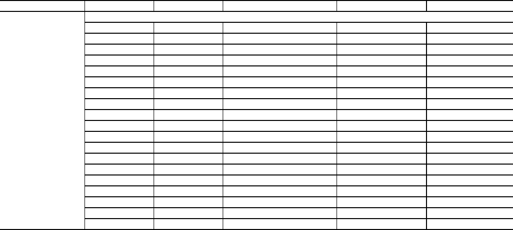
63
APPENDIX A — LOCAL DISPLAY TABLES (cont)
Operating Mode and Sub-Mode Directory
SUB-MODE ITEM DISPLAY ITEM DESCRIPTION CCN POINT COMMENT
MODE
MODES CONTROLLING UNIT
MD01 OFF/ON FSM controlling Chiller MODE_1
MD02 OFF/ON WSM controlling Chiller MODE_2
MD03 OFF/ON Master/Slave control MODE_3
MD05 OFF/ON Ramp Load Limited MODE_5
MD06 OFF/ON Timed Override in effect MODE_6
MD07 OFF/ON Low Cooler Suction TempA MODE_7
MD09 OFF/ON Slow Change Override MODE_9
MD10 OFF/ON Minimum OFF time active MODE_10
MD13 OFF/ON Dual Setpoint MODE_13
MD14 OFF/ON Temperature Reset MODE_14
MD15 OFF/ON Demand Limited MODE_15
MD16 OFF/ON Cooler Freeze Protection MODE_16
MD17 OFF/ON Low Temperature Cooling MODE_17
MD18 OFF/ON High Temperature Cooling MODE_18
MD19 OFF/ON Making ICE MODE_19
MD20 OFF/ON Storing ICE MODE_20
MD21 OFF/ON High SCT Circuit A MODE_21
MD23 OFF/ON Minimum Comp. On Time MODE_23
MD24 OFF/ON Pump Off Delay Time MODE_24
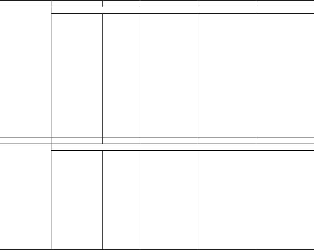
64
APPENDIX A — LOCAL DISPLAY TABLES (cont)
Alarms Mode and Sub-Mode Directory
SUB-MODE ITEM DISPLAY ITEM DESCRIPTION CCN POINT COMMENT
CRNT
CURRENTLY ACTIVE ALARMS
AA01
AA02
AA03
AA04
AA05
AA06
AA07
AA08
AA09
AA10
AA11
AA12
AA13
AA14
AA15
AA16
AA17
AA18
AA19
AA20
AA21
AA22
AA23
AA24
AA25
AXXX
TXXX
PXXX
Current Alarms 1-25
Alarms are shown as
AXXX
Alerts are shown as TXXX
RCRN NO/YES Reset All Current Alarms ALRESET
HIST
ALARM HISTORY
AL01
AL02
AL03
AL04
AL05
AL06
AL07
AL08
AL09
AL10
AL11
AL12
AL13
AL14
AL15
AL16
AL17
AL18
AL19
AL20
AXXX
TXXX
PXXX
Alarm History 1-20
Alarms are shown as
AXXX
Alerts are shown as TXXX

65
APPENDIX B — CCN TABLES
CCN DISPLAY TABLES — A_UNIT (General Unit Parameters
CCN DISPLAY TABLES — CIRCA_AN (Circuit A Analog Parameters)
CCN DISPLAY TABLES — CIRCADIO (Circuit A Discrete Inputs/Outputs)
DESCRIPTION VALUE UNITS POINT NAME FORCIBLE
Control Mode 10-char ASCII STAT N
Occupied No/Yes OCC N
CCN Chiller Stop/Start CHIL_S_S Y
Alarm State 6-char ASCII ALM N
Active Demand Limit NNN % DEM_LIM Y
Override Modes in Effect No/Yes MODE N
Percent Total Capacity NNN % CAP_T N
Requested Stage NN STAGE N
Active Setpoint NNN.n degF SP N
Control Point NNN.n degF CTRL_PNT Y
Entering Fluid Temp NNN.n degF EWT N
Leaving Fluid Temp NNN.n degF LWT N
Emergency Stop Enable/EMStop EMSTOP Y
Minutes Left for Start 5-char ASCII MIN_LEFT N
PUMPS
Cooler Pump Relay Off/On COOLPUMP N
Condenser Pump Off/On CONDPUMP N
Cooler Flow Switch Off/On COOLFLOW N
DESCRIPTION VALUE UNITS POINT NAME FORCIBLE
CIRCUIT A ANALOG VALUES
Percent Total Capacity NNN % CAPA_T N
Percent Available Cap. NNN % CAPA_A N
Discharge Pressure NNN.n PSIG DP_A N
Suction Pressure NNN.n PSIG SP_A N
Head Setpoint NNN.n degF HSP N
Saturated Condensing Tmp NNN.n degF TMP_SCTA N
Saturated Suction Temp NNN.n degF TMP_SSTA N
Compr Return Gas Temp NNN.n degF TMP_RGTA N
Discharge Gas Temp NNN.n degF DISGAS N
Suction Superheat Temp NNN.n deltaF SH_A N
DESCRIPTION VALUE UNITS POINT NAME FORCIBLE
CIRC. A DISCRETE OUTPUTS
Compressor A1 Relay Off/On K_A1_RLY N
Compressor A2 Relay Off/On K_A2_RLY N
Compressor A3 Relay Off/On K_A3_RLY
Minimum Load Valve Relay Off/On MLV_RLY N
CIRC. A DISCRETE INPUTS
Compressor A1 Feedback Off/On K_A1_FBK N
Compressor A2 Feedback Off/On K_A2_FBK N
Compressor A3 Feedback Off/On K_A3_FBK

66
APPENDIX B — CCN TABLES (cont)
CCN DISPLAY TABLES — OPTIONS (Unit Parameters)
CCN MAINTENANCE TABLES — STRTHOUR
DESCRIPTION VALUE UNITS POINT NAME FORCIBLE
UNIT ANALOG VALUES
Cooler Entering Fluid NNN.n degF COOL_EWT N
Cooler Leaving Fluid NNN.n degF COOL_LWT N
Condenser Entering Fluid NNN.n degF COND_EWT N
Condenser Leaving Fluid NNN.n degF COND_LWT N
Lead/Lag Leaving Fluid NNN.n degF DUAL_LWT N
TEMPERATURE RESET
4-20 ma Reset Signal NN.n milliAmps RST_MA N
Outside Air Temperature NNN.n degF OAT Y
Space Temperature NNN.n degF SPT Y
DEMAND LIMIT
4-20 ma Demand Signal NN.n milliAmps LMT_MA N
Demand Limit Switch 1 Off/On DMD_SW1 N
Demand Limit Switch 2 Off/On DMD_SW2 N
CCN Loadshed Signal N DL_STAT N
MISCELLANEOUS
Dual Setpoint Switch Off/On DUAL_IN N
Cooler LWT Setpoint NNN.n degF LWT_SP N
Ice Done Off/On ICE_DONE N
DESCRIPTION VALUE UNITS POINT NAME
Machine Operating Hours NNNNNN hours HR_MACH
Machine Starts NNNNNN CY_MACH
Compressor A1 Run Hours NNNNNN.n hours HR_A1
Compressor A2 Run Hours NNNNNN.n hours HR_A2
Compressor A3 Run Hours NNNNNN.n hours HR_A3
Compressor A1 Starts NNNNNN CY_A1
Compressor A2 Starts NNNNNN CY_A2
Compressor A3 Starts NNNNNN CY_A3
PUMP HOURS
Cooler Pump Run Hours NNNNNN.n hours HR_CPUMP
Condenser Pump Run Hours NNNNNN.n hours HR_DPUMP

67
APPENDIX B — CCN TABLES (cont)
CCN MAINTENANCE TABLES — CURRMODS
CCN MAINTENANCE TABLES — ALARMS
CCN MAINTENANCE TABLES — VERSIONS
DESCRIPTION VALUE POINT NAME
CSM controlling Chiller Off/On MODE_1
WSM controlling Chiller Off/On MODE_2
Master/Slave control Off/On MODE_3
Ramp Load Limited Off/On MODE_5
Timed Override in effect Off/On MODE_6
Low Cooler Suction TempA Off/On MODE_7
Slow Change Override Off/On MODE_9
Minimum OFF time active Off/On MODE_10
Dual Setpoint Off/On MODE_13
Temperature Reset Off/On MODE_14
Demand Limited Off/On MODE_15
Cooler Freeze Protection Off/On MODE_16
Low Temperature Cooling Off/On MODE_17
High Temperature Cooling Off/On MODE_18
Making ICE Off/On MODE_19
Storing ICE Off/On MODE_20
High SCT Circuit A Off/On MODE_21
Minimum Comp. On Time Off/On MODE_23
Pump Off Delay Time Off/On MODE_24
Low Sound Mode Off/On MODE_25
DESCRIPTION VALUE POINT NAME
Active Alarm #1 4-char ASCII ALARM01C
Active Alarm #2 4-char ASCII ALARM02C
Active Alarm #3 4-char ASCII ALARM03C
Active Alarm #4 4-char ASCII ALARM04C
Active Alarm #5 4-char ASCII ALARM05C
Active Alarm #6 4-char ASCII ALARM06C
Active Alarm #7 4-char ASCII ALARM07C
Active Alarm #8 4-char ASCII ALARM08C
Active Alarm #9 4-char ASCII ALARM09C
Active Alarm #10 4-char ASCII ALARM10C
Active Alarm #11 4-char ASCII ALARM11C
Active Alarm #12 4-char ASCII ALARM12C
Active Alarm #13 4-char ASCII ALARM13C
Active Alarm #14 4-char ASCII ALARM14C
Active Alarm #15 4-char ASCII ALARM15C
Active Alarm #16 4-char ASCII ALARM16C
Active Alarm #17 4-char ASCII ALARM17C
Active Alarm #18 4-char ASCII ALARM18C
Active Alarm #19 4-char ASCII ALARM19C
Active Alarm #20 4-char ASCII ALARM20C
Active Alarm #21 4-char ASCII ALARM21C
Active Alarm #22 4-char ASCII ALARM22C
Active Alarm #23 4-char ASCII ALARM23C
Active Alarm #24 4-char ASCII ALARM24C
Active Alarm #25 4-char ASCII ALARM25C
DESCRIPTION VERSION VALUE
AUX CESR131333- 5-char ASCII
MBB CESR131279- 5-char ASCII
EMM CESR131174- 5-char ASCII
MARQUEE CESR131171- 5-char ASCII
NAVIGATOR CESR130227- 5-char ASCII

68
APPENDIX B — CCN TABLES (cont)
CCN MAINTENANCE TABLES — LOADFACT
CCN MAINTENANCE TABLES — LEARNFNS
CCN MAINTENANCE TABLES — PM-STRN
CCN MAINTENANCE TABLES — TESTMODE
DESCRIPTION VALUE UNITS POINT NAME
CAPACITY CONTROL
Load/Unload Factor NNN SMZ
Control Point NNN.n degF CTRL_PNT
Entering Fluid Temp NNN.n degF EWT
Leaving Fluid Temp NNN.n degF LWT
Ramp Load Limited Off/On MODE_5
Slow Change Override Off/On MODE_9
Cooler Freeze Protection Off/On MODE_16
Low Temperature Cooling Off/On MODE_17
High Temperature Cooling Off/On MODE_18
Minimum Comp. On Time Off/On MODE_23
DESCRIPTION VALUE UNITS POINT NAME
SCT Delta for Comp A1 NNN.n deltaF A1SCTDT
SCT Delta for Comp A2 NNN.n deltaF A2SCTDT
SCT Delta for Comp A3 NNN.n deltaF A3SCTDT
SAGP for Compressor A1 NNN.n SAGA1P
SAGM for Compressor A1 NNN.n SAGA1M
SAGP for Compressor A2 NNN.n SAGA2P
SAGM for Compressor A2 NNN.n SAGA2M
SAGP for Compressor A3 NNN.n SAGA3P
SAGM for Compressor A3 NNN.n SAGA3M
Reset short loop gain Yes/No RESET_GN
DESCRIPTION VALUE UNITS POINT NAME
Strainer Srvc Interval NNNNN hours SI_STRNR
Strainer Srvc Countdown NNNNN hours ST_CDOWN
Strainer Maint. Done No/Yes ST_MAINT
Strainer Maint. Date 15-char ASCII STRN_PM0
Strainer Maint. Date 15-char ASCII STRN_PM1
Strainer Maint. Date 15-char ASCII STRN_PM2
Strainer Maint. Date 15-char ASCII STRN_PM3
Strainer Maint. Date 15-char ASCII STRN_PM4
DESCRIPTION VALUE UNITS POINT NAME
Service Test Mode Off/On NET_CTRL
Compressor A1 Relay Off/On S_A1_RLY
Compressor A2 Relay Off/On S_A2_RLY
Compressor A3 Relay Off/On S_A3_RLY
Cooler Pump Relay Off/On S_CLPMP
Condenser Pump Off/On S_CNDPMP
Comp A1 Unload Time NN secs S_A1ULTM
Remote Alarm Relay Off/On S_ALM

69
APPENDIX B — CCN TABLES (cont)
CCN MAINTENANCE TABLES — RUNTEST
CCN MAINTENANCE TABLES — DUALCHIL
DESCRIPTION VALUE UNITS POINT NAME
Percent Total Capacity NNN % CAPA_T
Percent Available Cap. NNN % CAPA_A
Discharge Pressure NNN.n PSIG DP_A
Suction Pressure NNN.n PSIG SP_A
Saturated Condensing Tmp NNN.n degF TMP_SCTA
Saturated Suction Temp NNN.n degF TMP_SSTA
Compr Return Gas Temp NNN.n degF TMP_RGTA
Discharge Gas Temp NNN.n degF DISGAS
Suction Superheat Temp NNN.n deltaF SH_A
Compressor A1 Relay Off/On K_A1_RLY
Compressor A2 Relay Off/On K_A2_RLY
Compressor A3 Relay Off/On K_A3_RLY
Minimum Load Valve Relay Off/On MLV_RLY
Compressor A1 Feedback Off/On K_A1_FBK
Compressor A2 Feedback Off/On K_A2_FBK
Compressor A3 Feedback Off/On K_A3_FBK
Outside Air Temperature NNN.n degF OAT
Space Temperature NNN.n degF SPT
Cooler Pump Relay Off/On COOLPUMP
Condenser Pump Off/On CONDPUMP
Cooler Entering Fluid NNN.n degF COOL_EWT
Cooler Leaving Fluid NNN.n degF COOL_LWT
Cooler Flow Switch Off/On COOLFLOW
DESCRIPTION VALUE UNITS POINT NAME
Dual Chiller Link Good? No/Yes DC_LINK
Master Chiller Role 12-char ASCII MC_ROLE
Slave Chiller Role 12-char ASCII SC_ROLE
Lead Chiller Ctrl Point NNN.n degF LEAD_CP
Lag Chiller Ctrl Point NNN.n degF LAG_CP
Control Point NNN.n degF CTRL_PNT
Cool EnteringFluid-Slave NNN.n degF COOLEWTS
Cool Leaving Fluid-Slave NNN.n degF COOLLWTS
Cooler Entering Fluid NNN.n degF COOL_EWT
Cooler Leaving Fluid NNN.n degF COOL_LWT
Lead/Lag Leaving Fluid NNN.n degF DUAL_LWT
Percent Avail.Capacity NNN % CAP_A
Percent Avail.Cap.Slave NNN % CAP_A_S
Lag Start Delay Time 5-char ASCII LAGDELAY
Load/Unload Factor NNN SMZ
Load/Unload Factor-Slave NNNN SMZSLAVE
Lead SMZ Clear Commanded No/Yes LEADSMZC
Lag SMZ Clear Commanded No/Yes LAG_SMZC
Lag Commanded Off? No/Yes LAG_OFF
Dual Chill Lead CapLimit NNN.n % DCLDCAPL
Dual Chill Lag CapLimit NNN.n % DCLGCAPL
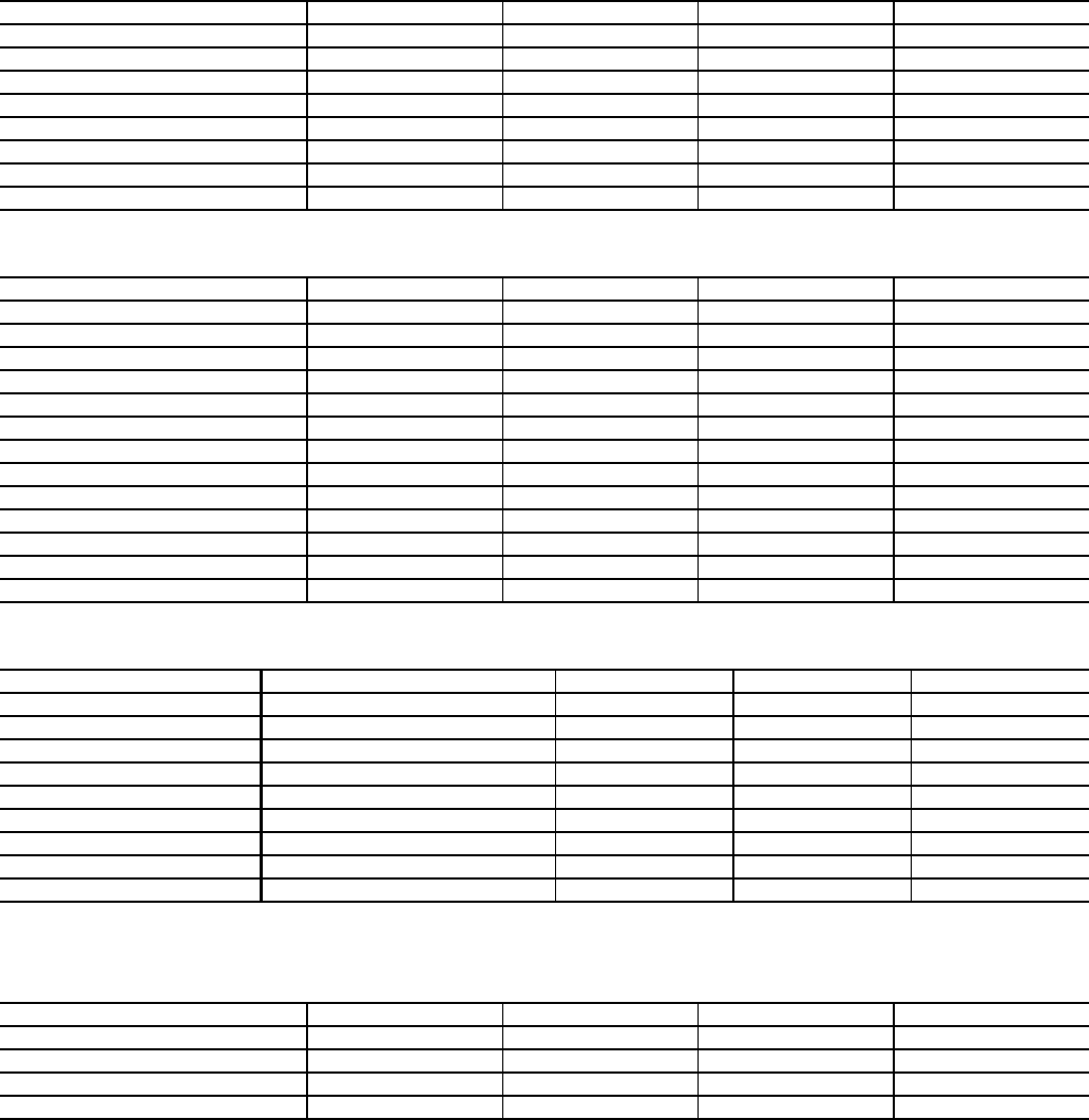
70
APPENDIX B — CCN TABLES (cont)
CCN CONFIGURATION TABLES — UNIT (Unit Configuration)
CCN CONFIGURATION TABLES — OPTIONS1 (Options 1 Configuration)
CCN CONFIGURATION TABLES — OPTIONS2 (Options 2 Configuration)
CCN CONFIGURATION TABLES — SCHEDOVR (Timed Override Setup)
DESCRIPTION VALUE DEFAULT UNITS POINT NAME
Unit Type N UNIT_TYP
Unit Size NNN tons SIZE
Compressor A1 Size NNN tons SIZE_A1
Compressor A2 Size NNN tons SIZE_A2
Compressor A3 Size NNN tons SIZE_A3
Suction Superheat Setpt NN.n deltaF SH_SP
Compressor A1 Digital? No/Yes CPA1TYPE
Maximum A1 Unload Time NN secs MAXULTME
DESCRIPTION VALUE DEFAULT UNITS POINT NAME
Cooler Fluid N FLUIDTYP
Minimum Load Vlv Select No/Yes MLV_FLG
Return Gas Sensor Enable Dsable/Enable RGT_ENA
Enable OAT Sensor Dsable/Enable OAT_ENA
Dischrge Gas Temp Enable Dsable/Enable DISGASEN
CSB Boards Enable Dsable/Enable CSB_ENA
Reverse Rotation Enable Dsable/Enable REVR_ENA
Cooler Pump Control Off/On CPC
Cooler Pump Shutdown Dly NN mins PUMP_DLY
EMM Module Installed No/Yes EMM_BRD
Enable Condenser Pump N CONDPMPE
Enable Cond Wtr Sensors Dsable/Enable CONDWTRS
Enable Cond Flow Switch Dsable/Enable CONDFLSW
DESCRIPTION VALUE DEFAULT UNITS POINT NAME
Control Method N CONTROL
Loading Sequence Select N SEQ_TYPE
Lead/Lag Circuit Select N LEAD_TYP
Cooling Setpoint Select N CLSP_TYP
Ramp Load Select Dsable/Enable RAMP_EBL
High LCW Alert Limit NN.n deltaF LCW_LMT
Minutes off time NN mins DELAY
Deadband Multiplier N.n Z_GAIN
Ice Mode Enable Dsable/Enable ICE_CNFG
DESCRIPTION VALUE DEFAULT UNITS POINT NAME
Schedule Number NN 1 SCHEDNUM
Override Time Limit N 0 hours OTL
Timed Override Hours N 0 hours OVR_EXT
Timed Override No/Yes No TIMEOVER
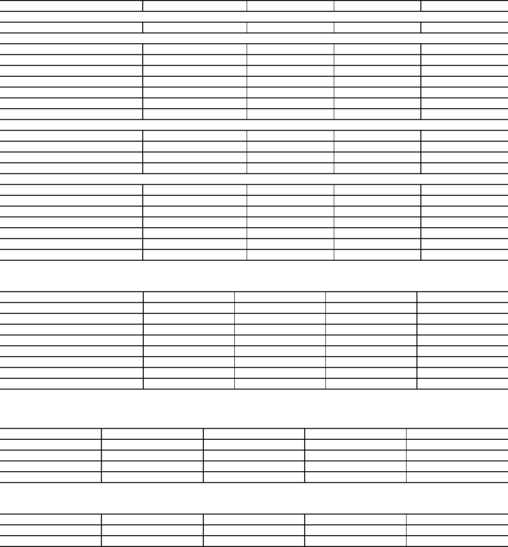
71
APPENDIX B — CCN TABLES (cont)
CCN CONFIGURATION TABLES — RESETCON (Temperature Reset and Demand Limit)
CCN CONFIGURATION TABLES — DUALCHIL (Dual Chiller Configuration Settings)
CCN CONFIGURATION TABLES — DISPLAY (Marquee Display SETUP)
CCN CONFIGURATION TABLES — HPA
DESCRIPTION VALUE DEFAULT UNITS POINT NAME
COOLING RESET
Cooling Reset Type N 0 CRST_TYP
4-20 MA RESET
4-20 - Degrees Reset NNN.n deltaF 420_DEG
REMOTE RESET
Remote - No Reset Temp NNN.n degF REM_NO
Remote - Full Reset Temp NNN.n degF REM_FULL
Remote - Degrees Reset NNN.n deltaF REM_DEG
RETURN TEMPERATURE RESET
Return - No Reset Temp NNN.n deltaF RTN_NO
Return - Full Reset Temp NNN.n deltaF RTN_FULL
Return - Degrees Reset NNN.n deltaF RTN_DEG
DEMAND LIMIT
Demand Limit Select N DMD_CTRL
Demand Limit at 20 mA NNN % DMT20MA
Loadshed Group Number NN SHED_NUM
Loadshed Demand Delta NN % SHED_DEL
Maximum Loadshed Time NNN mins SHED_TIM
Demand Limit Switch 1 NNN % DLSWSP1
Demand Limit Switch 2 NNN % DLSWSP2
DESCRIPTION VALUE DEFAULT UNITS POINT NAME
LEAD/LAG
Lead/Lag Chiller Enable Dsable/Enable LL_ENA
Master/Slave Select Master/Slave MS_SEL
Slave Address NNN SLV_ADDR
Lead/Lag Balance Select N LL_BAL
Lead/Lag Balance Delta NNN hours LL_BAL_D
Lag Start Delay NN mins LL_DELAY
Parallel Configuration No/Yes PA R A L L E L
DESCRIPTION VALUE DEFAULT UNITS POINT NAME
Service Password NNNN PASSWORD
Password Enable Dsable/Enable PASS_EBL
Metric Display Off/On DISPUNIT
Language Selection N LANGUAGE
DESCRIPTION VALUE DEFAULT UNITS POINT NAME
SCT Delta for Comp A1 NNN.n deltaF A1SCTDT
SCT Delta for Comp A2 NNN.n deltaF A2SCTDT
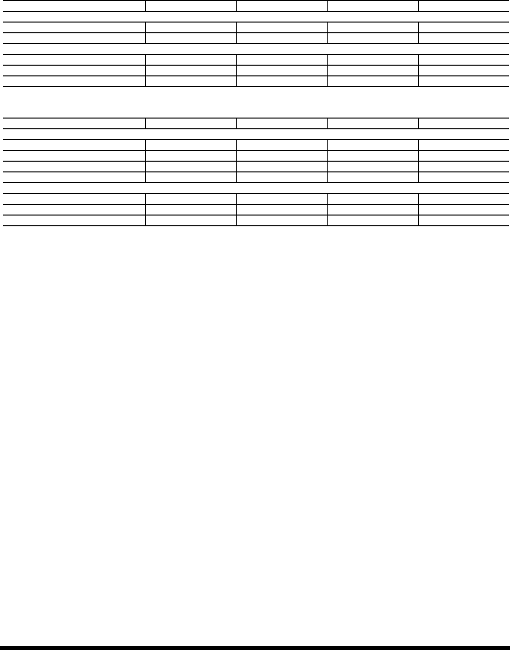
Manufacturer reserves the right to discontinue, or change at any time, specifications or designs without notice and without incurring obligations.
Catalog No. 04-53300053-01 Printed in U.S.A. Form 30MP-1T Pg 72 1-10 Replaces: New
Copyright 2010 Carrier Corporation
APPENDIX B — CCN TABLES (cont)
CCN SERVICE TABLES — SERVICE
CCN SETPOINT TABLES — SETPOINT
DESCRIPTION VALUE DEFAULT UNITS POINT NAME
SERVICE
Brine Freeze Point NNN.n degF BRN_FRZ
COMPRESSOR ENABLE
Enable Compressor A1 Dsable/Enable ENABLEA1
Enable Compressor A2 Dsable/Enable ENABLEA2
Enable Compressor A3 Dsable/Enable ENABLEA3
DESCRIPTION VALUE DEFAULT UNITS POINT NAME
COOLING
Cooling Setpoint 1 NNN.n degF CSP1
Cooling Setpoint 2 NNN.n degF CSP2
ICE Setpoint NNN.n degF CSP3
RAMP LOADING
Cooling Ramp Loading N.n CRAMP
Brine Freeze Point NNN.n degF BRN_FRZ

Manufacturer reserves the right to discontinue, or change at any time, specifications or designs without notice and without incurring obligations.
Catalog No. 04-53300053-01 Printed in U.S.A. Form 30MP-1T Pg CL-1 1-10 Replaces: New
START-UP CHECKLIST FOR 30MP LIQUID CHILLER
(Remove and use for job file.)
A. Preliminary Information
JOB NAME _______________________________________________________________________________
LOCATION _______________________________________________________________________________
INSTALLING CONTRACTOR _________________________________________________________________
DISTRIBUTOR ____________________________________________________________________________
START-UP PERFORMED BY _________________________________________________________________
EQUIPMENT: Chiller: MODEL NO. SERIAL NO.
COMPRESSORS:
B. Preliminary Equipment Check (Yes or No)
IS THERE ANY SHIPPING DAMAGE? IF SO, WHERE
_________________________________________________________________________________________
WILL THIS DAMAGE PREVENT UNIT START-UP?
CHECK POWER SUPPLY. DOES IT AGREE WITH UNIT?
HAS THE CIRCUIT PROTECTION BEEN SIZED AND INSTALLED PROPERLY? (refer to Installation Instructions)
ARE THE POWER WIRES TO THE UNIT SIZED AND INSTALLED PROPERLY? (refer to Installation Instructions)
HAS THE GROUND WIRE BEEN CONNECTED?
ARE ALL ELECTRICAL TERMINALS TIGHT?
ON BRINE UNITS, HAS THE COOLER FLUID BEEN PROPERLY PROTECTED FROM FREEZING TO AT
LEAST 15° F (8.3° C) BELOW THE LOWEST ANTICIPATED LEAVING FLUID TEMPERATURE SET POINT?
HAVE THE MAIN BASE BOARD, ENERGY MANAGEMENT MODULE (OPTION) AND CONTROL RELAY
CONNECTIONS BEEN CHECK FOR TIGHTNESS?
CIRCUIT A
MODEL NO.
SERIAL NO.

CL-2
C. Unit Start-Up (insert check mark as each item is completed)
CHILLER HAS BEEN PROPERLY INTERLOCKED WITH THE AUXILIARY CONTACTS OF THE CHILLED
FLUID PUMP STARTER.
CHILLER HAS BEEN PROPERLY INTERLOCKED WITH THE AUXILIARY CONTACTS OF THE
CONDENSER WATER PUMP STARTER.
CRANKCASE HEATERS HAVE BEEN ENERGIZED FOR A MINIMUM OF 24 HOURS PRIOR TO START-UP.
(30MPA UNITS ONLY)
COMPRESSOR OIL LEVEL IS CORRECT.
LIQUID LINE SERVICE VALVE IS BACKSEATED (30MPA UNITS ONLY).
SET POINT SHOULD BE ADJUSTED TO THE DESIRED COOLER LEAVING FLUID TEMPERATURE.
(refer to installation instructions).
LEAK CHECK THOROUGHLY: CHECK ALL COMPRESSORS, CONDENSER MANIFOLDS AND HEADERS,
TXVs, SOLENOID VALVES, FILTER DRIERS, FUSIBLE PLUGS, THERMISTORS, AND COOLER CONNEC-
TIONS USING ELECTRONIC LEAK DETECTOR.
LOCATE, REPAIR, AND REPORT ANY REFRIGERANT LEAKS.
CHECK VOLTAGE IMBALANCE: AB AC BC
AB + AC + BC (divided by 3) = AVERAGE VOLTAGE = V
MAXIMUM DEVIATION FROM AVERAGE VOLTAGE =
IF OVER 2% VOLTAGE IMBALANCE, DO NOT ATTEMPT TO START CHILLER!
CALL LOCAL POWER COMPANY FOR ASSISTANCE.
INCOMING POWER VOLTAGE TO CHILLER MODULES IS WITHIN RATED UNIT VOLTAGE
RANGE.
SYSTEM FLUID VOLUME IN LOOP: GAL (L)
REFER TO INSTALLATION INSTRUCTIONS FOR MINIMUM FLUID VOLUME
VOLTAGE IMBALANCE = (MAX. DEVIATION) x 100 = % VOLTAGE IMBALANCE
AVERAGE VOLTAGE

CL-3
C. Unit Start-Up (cont)
CHECK PRESSURE DROP ACROSS COOLER.
FLUID ENTERING COOLER: PSIG (kPa)
FLUID LEAVING COOLER: PSIG (kPa)
(PSIG DIFFERENCE) x 2.31 = FT OF FLUID PRESSURE DROP =
PLOT COOLER PRESSURE DROP ON PERFORMANCE DATA CHART (LOCATED IN INSTALLATION
INSTRUCTIONS LITERATURE) TO DETERMINE TOTAL GPM (L/s).
TOTAL GPM (L/s) = UNIT’S RATED MIN GPM (L/s) =
JOB’S SPECIFIED GPM (L/s) (if available):
NOTE: IF UNIT HAS LOW FLUID FLOW, FIND SOURCE OF PROBLEM: CHECK FLUID PIPING, IN-LINE
FLUID STRAINER, SHUT-OFF VALVES, CWP ROTATION, ETC.
COOLER LOOP FREEZE PROTECTION IF REQUIRED:
GALLONS (LITERS) ADDED:
PIPING INCLUDES ELECTRIC TAPE HEATERS IF PIPNG IS EXPOSED TO TEMPERATURES
BELOW FREEZING (Y/N):
COOLER/CONDENSER PROTECTION:
IN-LINE MINIMUM 40-MESH STRAINER INSTALLED WITHIN 10 FT OF THE COOLER/CONDENSER
WATER INLET.
COOLER: YES NO
CONDENSER: YES NO
VISUALLY CHECK MAIN BASE BOARD FOR THE FOLLOWING:
INSPECT ALL THERMISTORS AND TRANSDUCERS FOR POSSIBLE CROSSED WIRES.
CHECK TO BE SURE ALL WELL-TYPE THERMISTORS ARE FULLY INSERTED INTO THEIR
RESPECTIVE WELLS.
TO START THE CHILLER:
TURN THE EMERGENCY ON/OFF SWITCH (SW2) TO ON POSITION.
TURN THE ENABLE/OFF/REMOTE CONTACT SWITCH (SW1) TO THE ENABLE POSITION.
IF EQUIPPED WITH THE OPTIONAL SCROLLING MARQUEE, LEAVE THE ENABLE/OFF/REMOTE CONTACT
SWITCH (SW1) IN THE OFF POSITION.
NOTE: USE ESCAPE KEY TO GO UP ONE LEVEL IN THE STRUCTURE.
USE ARROW/ESCAPE KEYS TO ILLUMINATE RUN STATUS LED. PRESS ENTER KEY UNTIL
‘VERS’ IS DISPLAYED. PRESS ENTER KEY. RECORD INFORMATION ON THE FOLLOWING PAGE.
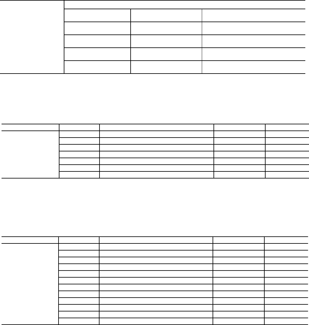
CL-4
C. Unit Start-Up (cont)
Record Software Versions
MODE — RUN STATUS
(PRESS ENTER AND ESCAPE SIMULTANEOUSLY TO OBTAIN SOFTWARE VERSIONS)
USE ARROW/ESCAPE KEYS TO ILLUMINATE CONFIGURATION LED. PRESS ENTER KEY. RECORD
INFORMATION BELOW.
UNIT (Configuration Settings)
PRESS ESCAPE KEY TO DISPLAY ‘UNIT’. PRESS DOWN ARROW KEY TO DISPLAY ‘OPT1’.
PRESS ENTER KEY. RECORD CONFIGURATION INFORMATION BELOW:
OPTIONS1 (Options Configuration)
PRESS ESCAPE KEY TO DISPLAY ‘OPT1’. PRESS DOWN ARROW KEY TO DISPLAY ‘OPT2’.
PRESS ENTER KEY.
RECORD CONFIGURATION INFORMATION ON NEXT PAGE.
VERS
SOFTWARE VERSION NUMBERS
AUX CESR131333-xx-xx
MBB CESR131279-xx-xx
EMM CESR131174-xx-xx
MARQ CESR131171-xx-xx
NAVI CESR130227-xx-xx
SUBMODE ITEM ITEM EXPANSION DISPLAY ENTRY
UNIT
UNIT CONFIGURATION
SIZE UNIT SIZE XXX
SZA.1 COMPRESSOR A1 SIZE XX
SZA.2 COMPRESSOR A2 SIZE XX
SZA.3 COMPRESSOR A3 SIZE XX
A1.TY COMPRESSOR A1 DIGITAL? NO/YES
MAX.T MAXIMUM A1 UNLOAD TIME XX
SUBMODE ITEM ITEM EXPANSION DISPLAY ENTRY
OPT1
UNIT OPTIONS 1 HARDWARE
FLUD COOLER FLUID X
MLV.S MINIMUM LOAD VALVE SELECT NO/YES
RG.EN RETURN GAS SENSOR ENABLE ENBL/DSBL
OAT.E ENABLE OAT SENSOR ENBL/DSBL
D.G.EN DISCHRGE GAS TEMP ENABLE ENBL/DSBL
CSB.E CSB BOARDS ENABLE ENBL/DSBL
CPC COOLER PUMP CONTROL ON/OFF
PM.DY COOLER PUMP SHUTDOWN DLY XX MIN
DPME ENABLE CONDENSER PUMP ENBL/DSBL
DFLS ENABLE COND FLOW SWITCH ENBL/DSBL
CDWS ENABLE COND WTR SENSORS ENBL/DSBL
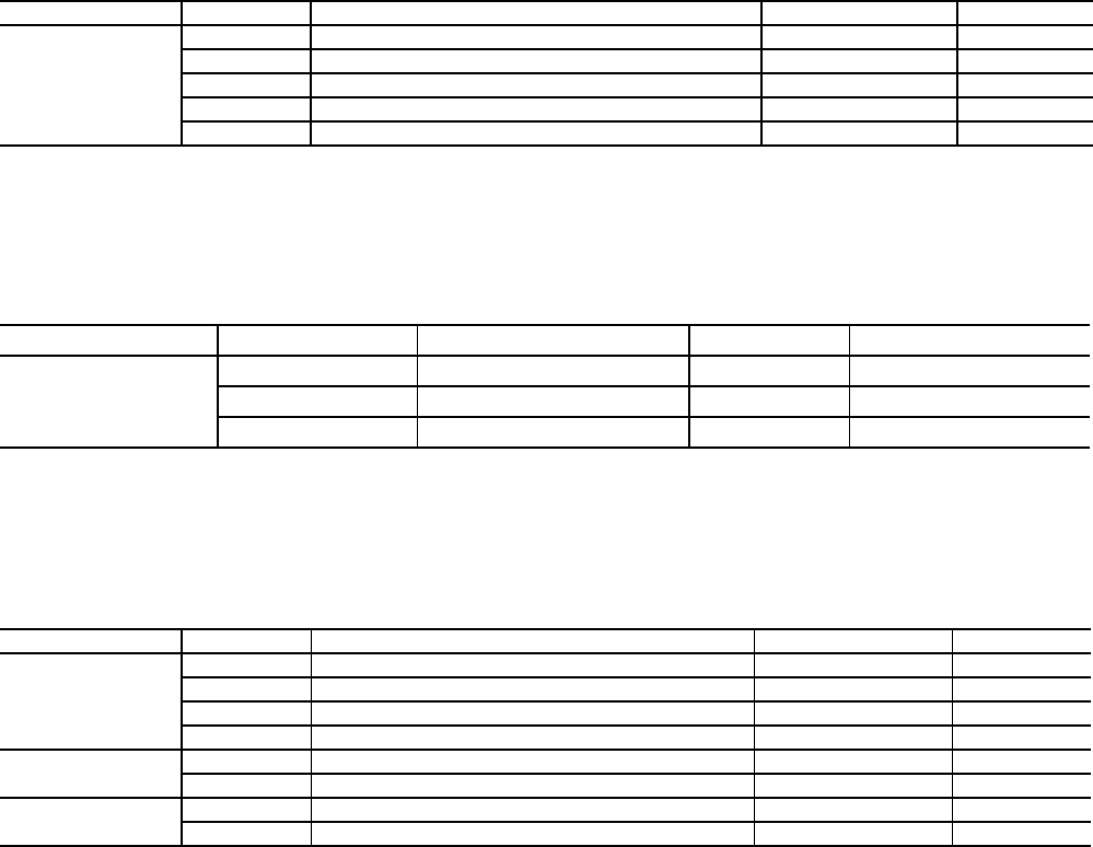
CL-5
C. Unit Start-Up (cont)
OPTIONS2 (Options Configuration)
PRESS ESCAPE KEY TO DISPLAY ‘OPT2’. PRESS DOWN ARROW KEY TO DISPLAY ‘CCN’.
PRESS ENTER KEY.
RECORD CONFIGURATION INFORMATION BELOW.
CCN (CCN Network Configuration)
PRESS ESCAPE KEY SEVERAL TIMES TO GET TO THE MODE LEVEL (BLANK DISPLAY). USE THE
ARROW KEYS TO SCROLL TO THE SET POINT LED. PRESS ENTER TO DISPLAY SETPOINTS.
RECORD CONFIGURATION INFORMATION BELOW:
SETPOINT
COMPONENT TEST
USE ESCAPE/ARROW KEYS TO ILLUMINATE CONFIGURATION LED. PRESS ENTER TO DISPLAY ‘DISP’.
PRESS ENTER AGAIN TO DISPLAY ‘TEST’ FOLLOWED BY ‘OFF’. PRESS ENTER TO STOP DISPLAY AT
‘OFF’ AND ENTER AGAIN SO ‘OFF’ DISPLAY FLASHES. ‘PASS’ AND ‘WORD’ WILL FLASH IF PASSWORD
NEEDS TO BE ENTERED. PRESS ENTER TO DISPLAY PASSWORD FIELD AND USE THE ENTER KEY FOR
EACH OF THE FOUR PASSWORD DIGITS. USE ARROW KEYS IF PASSWORD IS OTHER THAN STANDARD.
AT FLASHING ‘OFF’ DISPLAY, PRESS THE UP ARROW KEY TO DISPLAY ‘ON’ AND PRESS ENTER. ALL LED
SEGMENTS AND MODE LEDS WILL LIGHT UP. PRESS ESCAPE TO STOP THE TEST. PRESS ESCAPE TO
RETURN TO THE ‘DISP’ DISPLAY. PRESS THE ESCAPE KEY AGAIN AND USE THE ARROW KEYS TO ILLU-
MINATE THE SERVICE TEST LED. PRESS ENTER TO DISPLAY ‘TEST’. PRESS ENTER TO STOP DISPLAY
AT ‘OFF’ AND ENTER AGAIN SO ‘OFF’ FLASHES. PRESS THE UP ARROW KEY AND ENTER TO ENABLE
THE MANUAL MODE. PRESS ESCAPE AND DISPLAY NOW SAYS ‘TEST’ ‘ON’. TURN SWITCH (SW1) TO
THE ENABLE POSITION.
PRESS THE DOWN ARROW TO DISPLAY ‘OUTS’. PRESS THE ENTER KEY TO DISPLAY ‘LL.SV’. PRESS
THE ENTER KEY TO STOP DISPLAY AT ‘OFF’ AND ENTER AGAIN SO ‘OFF’ FLASHES. PRESS THE UP
ARROW KEY AND ENTER TO TURN THE OUTPUT ON. PRESS ENTER SO THE ‘ON’ DISPLAY FLASHES,
PRESS THE DOWN ARROW KEY AND THEN ENTER TO TURN THE OUTPUT OFF. OUTPUTS WILL ALSO BE
TURNED OFF OR SENT TO 0% WHEN ANOTHER OUTPUT IS TURNED ON. CHECK OFF THE ITEMS IN THE
SERVICE TEST TABLE ON THE NEXT PAGE THAT APPLY AFTER BEING TESTED.
SUBMODE ITEM ITEM EXPANSION DISPLAY ENTRY
OPT2
UNIT OPTIONS 2 CONTROLS
CTRL CONTROL METHOD X
LCWT HIGH LCW ALERT LIMIT XX.X F
DELY MINUTES OFF TIME XX
ICE.M ICE MODE ENABLE ENBL/DSBL
SUB-MODE ITEM ITEM EXPANSION DISPLAY ENTRY
CCN
CCNA CCN ADDRESS XXX
CCNB CCN BUS NUMBER XXX
BAUD CCN BAUD RATE X
SUBMODE ITEM ITEM EXPANSION DISPLAY ENTRY
COOL
COOLING SETPOINTS
CSP.1 COOLING SETPOINT 1 XXX.X °F
CSP.2 COOLING SETPOINT 2 XXX.X °F
CSP.3 ICE SETPOINT XXX.X °F
HEAD HEAD PRESSURE SETPOINTS
H.DP HEAD SET POINT XXX.X °F
FRZ BRINE FREEZE SETPOINT
BR.FZ BRINE FREEZE POINT XXX.X °F
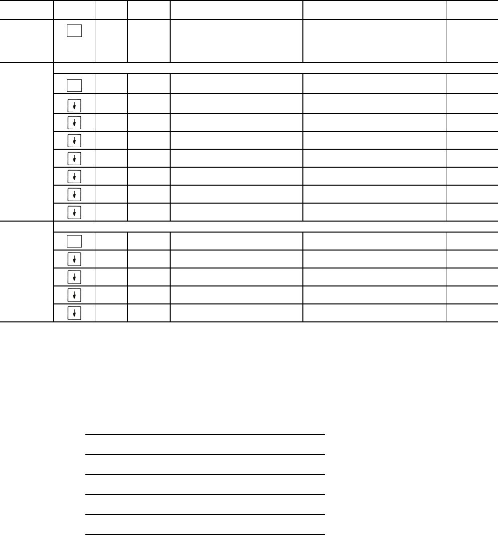
CL-6
C. Unit Start-Up (cont)
USE ESCAPE KEY TO RETURN TO ‘OUTS’ DISPLAY. PRESS DOWN ARROW TO DISPLAY ‘CMPA’.
PRESS ENTER KEY TO DISPLAY ‘CC.A1’. NOTE THAT UNLOADERS AND HOT GAS BYPASS SOLENOIDS
CAN BE TESTED BOTH WITH AND WITHOUT COMPRESSOR(S) RUNNING. MAKE SURE ALL SERVICE
VALVES ARE OPEN AND COOLER/CONDENSER PUMPS HAVE BEEN TURNED ON BEFORE STARTING
COMPRESSORS. CHECK OFF EACH ITEM AFTER SUCCESSFUL TEST. THE CONTROL WILL ONLY START
ONE COMPRESSOR PER MINUTE. WHEN AT THE DESIRED ITEM, PRESS THE ENTER KEY TWICE TO
MAKE THE ‘OFF’ FLASH. PRESS THE UP ARROW KEY AND ENTER TO TURN THE OUTPUT ON. CHECK
OFF THE ITEMS IN THE SERVICE TEST TABLE BELOW THAT APPLY AFTER BEING TESTED.
SERVICE TEST
USE ARROW/ESCAPE KEYS TO ILLUMINATE THE TEMPERATURES LED. PRESS ENTER TO DISPLAY
‘UNIT’. PRESS ENTER AND USE THE ARROW KEYS TO RECORD TEMPERATURES FOR
SENSORS BELOW.
SUB-MODE KEYPAD
ENTRY ITEM DISPLAY ITEM
EXPANSION COMMENT Completed
(Yes/No)
TEST
ON/OFF SERVICE TEST MODE To Enable Service Test Mode,
move Enable/Off/Remote
Contact switch to OFF. Change
TEST to ON. Move switch to
ENABLE.
OUTS
OUTPUTS AND PUMPS
CLR.P ON/OFF COOLER PUMP RELAY
CND.P ON/OFF CONDENSER PUMP
UL.TM 0 TO 15 COMP A1 UNLOAD TIME
CC.H ON/OFF CRANKCASE HEATER
CW.VO ON/OFF CONDENSER VALVE OPEN
CW.VC ON/OFF CONDENSER VALVE CLOSE
LL.SV ON/OFF LIQUID LINE SOLENOID
RMT.A ON/OFF REMOTE ALARM RELAY
CMPA
CIRCUIT A COMPRESSOR TEST
CC.A1 ON/OFF COMPRESSOR A1 RELAY
UL.TM 0 TO 15 COMP A1 UNLOAD TIME
CC.A2 ON/OFF COMPRESSOR A2 RELAY
CC.A3 ON/OFF COMPRESSOR A3 RELAY
MLV ON/OFF MINIMUM LOAD VALVE RELAY
ENTER
ENTER
ENTER
TEMPERATURE
CLWT
CEWT
CDET
CDLT
OAT or DLWT
SPT

CL-7
C. Unit Start-Up (cont)
ALL UNITS:
MEASURE THE FOLLOWING (MEASURE WHILE MACHINE IS IN A STABLE OPERATING CONDITION):
CHECK AND ADJUST SUPERHEAT AS REQUIRED.
CIRCUIT A
DISCHARGE PRESSURE
SUCTION PRESSURE
DISCHARGE LINE TEMP
SUCTION LINE TEMP
SATURATED COND TEMP
COOLER ENTERING FLUID
COOLER LEAVING FLUID
CONDENSER ENTERING FLUID
CONDENSER LEAVING FLUID

Manufacturer reserves the right to discontinue, or change at any time, specifications or designs without notice and without incurring obligations.
Catalog No. 04-53300053-01 Printed in U.S.A. Form 30MP-1T Pg CL-8 1-10 Replaces: New
Copyright 2010 Carrier Corporation
-
- - - - - - - - - - - - - - - - - - - - - - - - - - - - - - - - - - - - - - - - - - - - - - - - - - - - - - - - - - - - - - - - - - - - - - - - - - - - - - - - - - - - - - - - - - - - - - - - - - - - - - - - - - - - - - - - - - - - - - - - - - - - - - - - - - - - - - - - - - - - - - - - - - - - - - - - - - - - - - - - - - - - - - - - - - - - -- - - - - - - - - - - - - - - - - - - -
CUT ALONG DOTTED LINE CUT ALONG DOTTED LINE
C. Unit Start-Up (cont)
COMMENTS:
_________________________________________________________________________________________
_________________________________________________________________________________________
_________________________________________________________________________________________
_________________________________________________________________________________________
_________________________________________________________________________________________
_________________________________________________________________________________________
_________________________________________________________________________________________
_________________________________________________________________________________________
_________________________________________________________________________________________
_________________________________________________________________________________________
_________________________________________________________________________________________
_________________________________________________________________________________________
_________________________________________________________________________________________
_________________________________________________________________________________________
_________________________________________________________________________________________
_________________________________________________________________________________________
_________________________________________________________________________________________
_________________________________________________________________________________________
_________________________________________________________________________________________
_________________________________________________________________________________________
SIGNATURES:
START-UP TECHNICIAN ___________________________________________________________________
DATE __________________________________
CUSTOMER REPRESENTATIVE _____________________________________________________________
DATE___________________________________
