Carrier Evergreen 19Xr Users Manual
19XR to the manual 04da73d4-0b4a-4d5a-b5cf-630745b3c66b
2015-01-24
: Carrier Carrier-Evergreen-19Xr-Users-Manual-310990 carrier-evergreen-19xr-users-manual-310990 carrier pdf
Open the PDF directly: View PDF ![]() .
.
Page Count: 140 [warning: Documents this large are best viewed by clicking the View PDF Link!]
Manufacturer reserves the right to discontinue, or change at any time, specifications or designs without notice and without incurring obligations.
PC 211 Catalog No. 531-982 Printed in U.S.A. Form 19XR-5SS Pg 1 6-01 Replaces: 19XR-4SS
Book 2
Ta b 5 a
Start-Up, Operation, and Maintenance Instructions
SAFETY CONSIDERATIONS
Centrifugal liquid chillers are designed to provide safe and
reliable service when operated within design specifica-
tions. When operating this equipment, use good judgment
and safety precautions to avoid damage to equipment and
property or injury to personnel.
Be sure you understand and follow the procedures and
safety precautions contained in the chiller instructions as
well as those listed in this guide.
DO NOT VENT refrigerant relief valves within a building. Outlet
from rupture disc or relief valve must be vented outdoors in accor-
dance with the latest edition of ANSI/ASHRAE 15 (American
National Standards Institute/American Society of Heating, Refrigera-
tion, and Air Conditioning Engineers). The accumulation of refriger-
ant in an enclosed space can displace oxygen and cause asphyxiation.
PROVIDE adequate ventilation in accordance with ANSI/ASHRAE
15, especially for enclosed and low overhead spaces. Inhalation of
high concentrations of vapor is harmful and may cause heart irregular-
ities, unconsciousness, or death. Misuse can be fatal. Vapor is heavier
than air and reduces the amount of oxygen available for breathing.
Product causes eye and skin irritation. Decomposition products are
hazardous.
DO NOT USE OXYGEN to purge lines or to pressurize a chiller for
any purpose. Oxygen gas reacts violently with oil, grease, and other
common substances.
NEVER EXCEED specified test pressures, VERIFY the allowable
test pressure by checking the instruction literature and the design pres-
sures on the equipment nameplate.
DO NOT USE air for leak testing. Use only refrigerant or dry
nitrogen.
DO NOT VALVE OFF any safety device.
BE SURE that all pressure relief devices are properly installed and
functioning before operating any chiller.
RISK OF INJURY OR DEATH by electrocution. High voltage is
present on motor leads even though the motor is not running when a
solid-state or inside-delta mechanical starter is used. Open the power
supply disconnect before touching motor leads or terminals.
DO NOT WELD OR FLAMECUT any refrigerant line or vessel until
all refrigerant (liquid and vapor) has been removed from chiller.
Traces of vapor should be displaced with dry air or nitrogen and the
work area should be well ventilated. Refrigerant in contact with an
open flame produces toxic gases.
DO NOT USE eyebolts or eyebolt holes to rig chiller sections or the
entire assembly.
DO NOT work on high-voltage equipment unless you are a qualified
electrician.
DO NOT WORK ON electrical components, including control pan-
els, switches, starters, or oil heater until you are sure ALL POWER IS
OFF and no residual voltage can leak from capacitors or solid-state
components.
LOCK OPEN AND TAG electrical circuits during servicing. IF
WORK IS INTERRUPTED, confirm that all circuits are deenergized
before resuming work.
AVOID SPILLING liquid refrigerant on skin or getting it into the
eyes. USE SAFETY GOGGLES. Wash any spills from the skin with
soap and water. If liquid refrigerant enters the eyes, IMMEDIATELY
FLUSH EYES with water and consult a physician.
NEVER APPLY an open flame or live steam to a refrigerant cylinder.
Dangerous over pressure can result. When it is necessary to heat
refrigerant, use only warm (110 F [43 C]) water.
DO NOT REUSE disposable (nonreturnable) cylinders or attempt to
refill them. It is DANGEROUS AND ILLEGAL. When cylinder is
emptied, evacuate remaining gas pressure, loosen the collar and
unscrew and discard the valve stem. DO NOT INCINERATE.
CHECK THE REFRIGERANT TYPE before adding refrigerant to
the chiller. The introduction of the wrong refrigerant can cause dam-
age or malfunction to this chiller.
Operation of this equipment with refrigerants other than those
cited herein should comply with ANSI/ASHRAE 15 (latest edition).
Contact Carrier for further information on use of this chiller with other
refrigerants.
DO NOT ATTEMPT TO REMOVE fittings, covers, etc., while
chiller is under pressure or while chiller is running. Be sure pressure is
at 0 psig (0 kPa) before breaking any refrigerant connection.
CAREFULLY INSPECT all relief devices, rupture discs, and other
relief devices AT LEAST ONCE A YEAR. If chiller operates in a
corrosive atmosphere, inspect the devices at more frequent intervals.
DO NOT ATTEMPT TO REPAIR OR RECONDITION any relief
device when corrosion or build-up of foreign material (rust, dirt, scale,
etc.) is found within the valve body or mechanism. Replace the
device.
DO NOT install relief devices in series or backwards.
USE CARE when working near or in line with a compressed spring.
Sudden release of the spring can cause it and objects in its path to act
as projectiles.
DO NOT STEP on refrigerant lines. Broken lines can whip about and
release refrigerant, causing personal injury.
DO NOT climb over a chiller. Use platform, catwalk, or staging. Fol-
low safe practices when using ladders.
USE MECHANICAL EQUIPMENT (crane, hoist, etc.) to lift or
move inspection covers or other heavy components. Even if compo-
nents are light, use mechanical equipment when there is a risk of slip-
ping or losing your balance.
BE AWARE that certain automatic start arrangements CAN
ENGAGE THE STARTER, TOWER FAN, OR PUMPS. Open the
disconnect ahead of the starter, tower fans, or pumps.
USE only repair or replacement parts that meet the code requirements
of the original equipment.
DO NOT VENT OR DRAIN waterboxes containing industrial brines,
liquid, gases, or semisolids without the permission of your process
control group.
DO NOT LOOSEN waterbox cover bolts until the waterbox has been
completely drained.
DOUBLE-CHECK that coupling nut wrenches, dial indicators, or
other items have been removed before rotating any shafts.
DO NOT LOOSEN a packing gland nut before checking that the nut
has a positive thread engagement.
PERIODICALLY INSPECT all valves, fittings, and piping for corro-
sion, rust, leaks, or damage.
PROVIDE A DRAIN connection in the vent line near each pressure
relief device to prevent a build-up of condensate or rain water.
19XR,XRV
Hermetic Centrifugal Liquid Chillers
50/60 Hz
With PIC II Controls and HFC-134a
2
CONTENTS
Page
SAFETY CONSIDERATIONS . . . . . . . . . . . . . . . . . . . . . . 1
INTRODUCTION . . . . . . . . . . . . . . . . . . . . . . . . . . . . . . . . . . 4
ABBREVIATIONS AND EXPLANATIONS . . . . . . . . 4,5
CHILLER FAMILIARIZATION . . . . . . . . . . . . . . . . . . . . 5-7
Chiller Information Nameplate . . . . . . . . . . . . . . . . . . . . 5
System Components . . . . . . . . . . . . . . . . . . . . . . . . . . . . . 5
Cooler . . . . . . . . . . . . . . . . . . . . . . . . . . . . . . . . . . . . . . . . . . . . 5
Condenser . . . . . . . . . . . . . . . . . . . . . . . . . . . . . . . . . . . . . . . 5
Motor-Compressor . . . . . . . . . . . . . . . . . . . . . . . . . . . . . . . 5
Control Panel. . . . . . . . . . . . . . . . . . . . . . . . . . . . . . . . . . . . . 5
Factory-Mounted Starter or Variable
Frequency Drive (Optional). . . . . . . . . . . . . . . . . . . . . 7
Storage Vessel (Optional) . . . . . . . . . . . . . . . . . . . . . . . . 7
REFRIGERATION CYCLE . . . . . . . . . . . . . . . . . . . . . . . . . 7
MOTOR AND LUBRICATING OIL
COOLING CYCLE . . . . . . . . . . . . . . . . . . . . . . . . . . . . 7,8
VFD COOLING CYCLE. . . . . . . . . . . . . . . . . . . . . . . . . . . . 8
LUBRICATION CYCLE . . . . . . . . . . . . . . . . . . . . . . . . . . 8,9
Summary . . . . . . . . . . . . . . . . . . . . . . . . . . . . . . . . . . . . . . . . . 8
Details. . . . . . . . . . . . . . . . . . . . . . . . . . . . . . . . . . . . . . . . . . . . 8
Oil Reclaim System. . . . . . . . . . . . . . . . . . . . . . . . . . . . . . . 8
• PRIMARY OIL RECOVERY MODE
• SECONDARY OIL RECOVERY METHOD
STARTING EQUIPMENT . . . . . . . . . . . . . . . . . . . . . . . 9,10
Unit-Mounted Solid-State Starter
(Optional) . . . . . . . . . . . . . . . . . . . . . . . . . . . . . . . . . . . . . . 9
Unit-Mounted Wye-Delta Starter
(Optional) . . . . . . . . . . . . . . . . . . . . . . . . . . . . . . . . . . . . . 10
Unit-Mounted VFD (Optional) . . . . . . . . . . . . . . . . . . . . 10
CONTROLS. . . . . . . . . . . . . . . . . . . . . . . . . . . . . . . . . . . 10-45
Definitions . . . . . . . . . . . . . . . . . . . . . . . . . . . . . . . . . . . . . . 10
• ANALOG SIGNAL
• DISCRETE SIGNAL
General. . . . . . . . . . . . . . . . . . . . . . . . . . . . . . . . . . . . . . . . . . 11
PIC II System Components . . . . . . . . . . . . . . . . . . . . . . 11
• CHILLER VISUAL CONTROLLER (CVC)
• INTERNATIONAL CHILLER VISUAL
CONTROLLER (ICVC)
• INTEGRATED STARTER MODULE (ISM)
• CHILLER CONTROL MODULE (CCM)
• OIL HEATER CONTACTOR (1C)
• OIL PUMP CONTACTOR (2C)
• HOT GAS BYPASS CONTACTOR RELAY (3C)
(Optional)
• CONTROL TRANSFORMERS (T1, T2)
• OPTIONAL TRANSFORMER (T3)
CVC/ICVC Operation and Menus. . . . . . . . . . . . . . . . . 15
• GENERAL
• ALARMS AND ALERTS
• CVC/ICVC MENU ITEMS
• BASIC CVC/ICVC OPERATIONS (Using the Softkeys)
• TO VIEW STATUS
• OVERRIDE OPERATIONS
• TIME SCHEDULE OPERATION
• TO VIEW AND CHANGE SET POINTS
• SERVICE OPERATION
PIC II System Functions . . . . . . . . . . . . . . . . . . . . . . . . . 33
• CAPACITY CONTROL FIXED SPEED
• CAPACITY CONTROL VFD
• ECW CONTROL OPTION
• CONTROL POINT DEADBAND
• DIFFUSER CONTROL
• PROPORTIONAL BANDS AND GAIN
• DEMAND LIMITING
• CHILLER TIMERS
• OCCUPANCY SCHEDULE
Safety Controls. . . . . . . . . . . . . . . . . . . . . . . . . . . . . . . . . . 34
Page
Shunt Trip (Option) . . . . . . . . . . . . . . . . . . . . . . . . . . . . . . 35
Default Screen Freeze . . . . . . . . . . . . . . . . . . . . . . . . . . . 35
Ramp Loading. . . . . . . . . . . . . . . . . . . . . . . . . . . . . . . . . . . 36
Capacity Override . . . . . . . . . . . . . . . . . . . . . . . . . . . . . . . 36
High Discharge Temperature Control . . . . . . . . . . . . 36
Oil Sump Temperature Control . . . . . . . . . . . . . . . . . . 36
Oil Cooler . . . . . . . . . . . . . . . . . . . . . . . . . . . . . . . . . . . . . . . 36
Remote Start/Stop Controls . . . . . . . . . . . . . . . . . . . . . 36
Spare Safety Inputs . . . . . . . . . . . . . . . . . . . . . . . . . . . . . 36
Alarm (Trip) Output Contacts . . . . . . . . . . . . . . . . . . . . 37
Refrigerant Leak Detector . . . . . . . . . . . . . . . . . . . . . . . 37
Kilowatt Output. . . . . . . . . . . . . . . . . . . . . . . . . . . . . . . . . . 37
Remote Reset of Alarms. . . . . . . . . . . . . . . . . . . . . . . . . 37
Condenser Pump Control . . . . . . . . . . . . . . . . . . . . . . . 37
Condenser Freeze Prevention . . . . . . . . . . . . . . . . . . . 38
Evaporator Freeze Protection (ICVC Only). . . . . . . 38
Tower Fan Relay Low and High . . . . . . . . . . . . . . . . . . 38
Auto. Restart After Power Failure. . . . . . . . . . . . . . . . 38
Water/Brine Reset . . . . . . . . . . . . . . . . . . . . . . . . . . . . . . . 38
• RESET TYPE 1
• RESET TYPE 2
• RESET TYPE 3
Demand Limit Control Option . . . . . . . . . . . . . . . . . . . 39
Surge Prevention Algorithm
(Fixed Speed Chiller) . . . . . . . . . . . . . . . . . . . . . . . . . . 39
Surge Prevention Algorithm with VFD . . . . . . . . . . . 40
Surge Protection VFD Units . . . . . . . . . . . . . . . . . . . . . 40
Surge Protection (Fixed Speed Chiller) . . . . . . . . . . 40
• HEAD PRESSURE REFERENCE OUTPUT
Lead/Lag Control . . . . . . . . . . . . . . . . . . . . . . . . . . . . . . . . 40
• COMMON POINT SENSOR INSTALLATION
• CHILLER COMMUNICATION WIRING
• LEAD/LAG OPERATION
• FAULTED CHILLER OPERATION
• LOAD BALANCING
• AUTO. RESTART AFTER POWER FAILURE
Ice Build Control . . . . . . . . . . . . . . . . . . . . . . . . . . . . . . . . 43
• ICE BUILD INITIATION
• START-UP/RECYCLE OPERATION
• TEMPERATURE CONTROL DURING ICE BUILD
• TERMINATION OF ICE BUILD
• RETURN TO NON-ICE BUILD OPERATIONS
Attach to Network Device Control . . . . . . . . . . . . . . . 44
• ATTACHING TO OTHER CCN MODULES
Service Operation . . . . . . . . . . . . . . . . . . . . . . . . . . . . . . . 45
• TO ACCESS THE SERVICE SCREENS
• TO LOG OUT OF NETWORK DEVICE
• HOLIDAY SCHEDULING
START-UP/SHUTDOWN/RECYCLE
SEQUENCE . . . . . . . . . . . . . . . . . . . . . . . . . . . . . . . . 46,47
Local Start-Up . . . . . . . . . . . . . . . . . . . . . . . . . . . . . . . . . . . 46
Shutdown Sequence . . . . . . . . . . . . . . . . . . . . . . . . . . . . 47
Automatic Soft Stop Amps Threshold . . . . . . . . . . . 47
Chilled Water Recycle Mode . . . . . . . . . . . . . . . . . . . . . 47
Safety Shutdown . . . . . . . . . . . . . . . . . . . . . . . . . . . . . . . . 47
BEFORE INITIAL START-UP . . . . . . . . . . . . . . . . . . 48-64
Job Data Required . . . . . . . . . . . . . . . . . . . . . . . . . . . . . . 48
Equipment Required . . . . . . . . . . . . . . . . . . . . . . . . . . . . 48
Using the Optional Storage Tank
and Pumpout System . . . . . . . . . . . . . . . . . . . . . . . . . 48
Remove Shipping Packaging . . . . . . . . . . . . . . . . . . . . 48
Open Oil Circuit Valves . . . . . . . . . . . . . . . . . . . . . . . . . . 48
Tighten All Gasketed Joints and
Guide Vane Shaft Packing . . . . . . . . . . . . . . . . . . . . . 48
Check Chiller Tightness . . . . . . . . . . . . . . . . . . . . . . . . . 48
Refrigerant Tracer . . . . . . . . . . . . . . . . . . . . . . . . . . . . . . . 48
Leak Test Chiller . . . . . . . . . . . . . . . . . . . . . . . . . . . . . . . . 50
Standing Vacuum Test. . . . . . . . . . . . . . . . . . . . . . . . . . . 50
3
CONTENTS (cont)
Page
Chiller Dehydration . . . . . . . . . . . . . . . . . . . . . . . . . . . . . 53
Inspect Water Piping . . . . . . . . . . . . . . . . . . . . . . . . . . . . 53
Check Optional Pumpout Compressor
Water Piping . . . . . . . . . . . . . . . . . . . . . . . . . . . . . . . . . . 53
Check Relief Valves . . . . . . . . . . . . . . . . . . . . . . . . . . . . . 53
Inspect Wiring. . . . . . . . . . . . . . . . . . . . . . . . . . . . . . . . . . . 53
Carrier Comfort Network Interface. . . . . . . . . . . . . . . 54
Check Starter . . . . . . . . . . . . . . . . . . . . . . . . . . . . . . . . . . . 54
• MECHANICAL STARTER
• BENSHAW, INC. RediStart MICRO™
SOLID-STATE STARTER
• VFD STARTER
Oil Charge. . . . . . . . . . . . . . . . . . . . . . . . . . . . . . . . . . . . . . . 55
Power Up the Controls and
Check the Oil Heater . . . . . . . . . . . . . . . . . . . . . . . . . . 55
• SOFTWARE VERSION
Software Configuration . . . . . . . . . . . . . . . . . . . . . . . . . 55
Input the Design Set Points . . . . . . . . . . . . . . . . . . . . . 55
Input the Local Occupied Schedule
(OCCPC01S) . . . . . . . . . . . . . . . . . . . . . . . . . . . . . . . . . . 55
Input Service Configurations. . . . . . . . . . . . . . . . . . . . 55
• PASSWORD
• INPUT TIME AND DATE
• CHANGE CVC/ICVC CONFIGURATION
IF NECESSARY
• TO CHANGE THE PASSWORD
• TO CHANGE THE CVC/ICVC DISPLAY FROM
ENGLISH TO METRIC UNITS
• CHANGE LANGUAGE (ICVC ONLY)
• MODIFY CONTROLLER IDENTIFICATION
IF NECESSARY
• INPUT EQUIPMENT SERVICE PARAMETERS
IF NECESSARY
• CHANGE THE BENSHAW, INC., RediStart
MICRO SOFTWARE CONFIGURATION
IF NECESSARY
• VERIFY VFD CONFIGURATION AND CHANGE
PARAMETERS IF NECESSARY
• VFD CHILLER FIELD SET UP AND VERIFICATION
• VFD CONTROL VERIFICATION (Non-Running)
• VFD CONTROL VERIFICATION (Running)
• CONFIGURE DIFFUSER CONTROL IF
NECESSARY
• MODIFY EQUIPMENT CONFIGURATION
IF NECESSARY
Perform a Control Test . . . . . . . . . . . . . . . . . . . . . . . . . . 62
• COOLER CONDENSER PRESSURE TRANSDUCER
AND WATERSIDE FLOW DEVICE CALIBRATION
Check Optional Pumpout System
Controls and Compressor. . . . . . . . . . . . . . . . . . . . . 63
High Altitude Locations . . . . . . . . . . . . . . . . . . . . . . . . . 63
Charge Refrigerant Into Chiller . . . . . . . . . . . . . . . . . . 63
• CHILLER EQUALIZATION WITHOUT A
PUMPOUT UNIT
• CHILLER EQUALIZATION WITH
PUMPOUT UNIT
• TRIMMING REFRIGERANT CHARGE
INITIAL START-UP . . . . . . . . . . . . . . . . . . . . . . . . . . . . 64-66
Preparation . . . . . . . . . . . . . . . . . . . . . . . . . . . . . . . . . . . . . 64
Dry Run to Test Start-Up Sequence . . . . . . . . . . . . . 65
Check Motor Rotation . . . . . . . . . . . . . . . . . . . . . . . . . . . 65
Check Oil Pressure and Compressor Stop . . . . . . 65
To Prevent Accidental Start-Up. . . . . . . . . . . . . . . . . . 65
Check Chiller Operating Condition . . . . . . . . . . . . . . 65
Instruct the Customer Operator . . . . . . . . . . . . . . . . . 65
•COOLER-CONDENSER
• OPTIONAL PUMPOUT STORAGE TANK AND
PUMPOUT SYSTEM
• MOTOR COMPRESSOR ASSEMBLY
Page
• MOTOR COMPRESSOR LUBRICATION
SYSTEM
• CONTROL SYSTEM
• AUXILIARY EQUIPMENT
• DESCRIBE CHILLER CYCLES
• REVIEW MAINTENANCE
• SAFETY DEVICES AND PROCEDURES
• CHECK OPERATOR KNOWLEDGE
• REVIEW THE START-UP, OPERATION, AND
MAINTENANCE MANUAL
OPERATING INSTRUCTIONS . . . . . . . . . . . . . . . . . .66,67
Operator Duties . . . . . . . . . . . . . . . . . . . . . . . . . . . . . . . . . 66
Prepare the Chiller for Start-Up . . . . . . . . . . . . . . . . . 66
To Start the Chiller . . . . . . . . . . . . . . . . . . . . . . . . . . . . . . 66
Check the Running System . . . . . . . . . . . . . . . . . . . . . 66
To Stop the Chiller . . . . . . . . . . . . . . . . . . . . . . . . . . . . . . 66
After Limited Shutdown . . . . . . . . . . . . . . . . . . . . . . . . . 66
Preparation for Extended Shutdown . . . . . . . . . . . . 66
After Extended Shutdown . . . . . . . . . . . . . . . . . . . . . . . 67
Cold Weather Operation. . . . . . . . . . . . . . . . . . . . . . . . . 67
Manual Guide Vane Operation. . . . . . . . . . . . . . . . . . . 67
Refrigeration Log . . . . . . . . . . . . . . . . . . . . . . . . . . . . . . . 67
PUMPOUT AND REFRIGERANT TRANSFER
PROCEDURES . . . . . . . . . . . . . . . . . . . . . . . . . . . . . 67-71
Preparation . . . . . . . . . . . . . . . . . . . . . . . . . . . . . . . . . . . . . 67
Operating the Optional Pumpout Unit . . . . . . . . . . . 67
• TO READ REFRIGERANT PRESSURES
Chillers with Storage Tanks . . . . . . . . . . . . . . . . . . . . . 69
• TRANSFER REFRIGERANT FROM
PUMPOUT STORAGE TANK TO CHILLER
• TRANSFER REFRIGERANT FROM
CHILLER TO PUMPOUT STORAGE TANK
Chillers with Isolation Valves. . . . . . . . . . . . . . . . . . . . 70
• TRANSFER ALL REFRIGERANT TO
CHILLER CONDENSER VESSEL
• TRANSFER ALL REFRIGERANT TO
CHILLER COOLER VESSEL
• RETURN CHILLER TO NORMAL
OPERATING CONDITIONS
GENERAL MAINTENANCE . . . . . . . . . . . . . . . . . . . .71,72
Refrigerant Properties . . . . . . . . . . . . . . . . . . . . . . . . . . 71
Adding Refrigerant. . . . . . . . . . . . . . . . . . . . . . . . . . . . . . 71
Removing Refrigerant. . . . . . . . . . . . . . . . . . . . . . . . . . . 71
Adjusting the Refrigerant Charge . . . . . . . . . . . . . . . 71
Refrigerant Leak Testing . . . . . . . . . . . . . . . . . . . . . . . . 71
Leak Rate . . . . . . . . . . . . . . . . . . . . . . . . . . . . . . . . . . . . . . . 71
Test After Service, Repair, or Major Leak . . . . . . . . 71
• TESTING WITH REFRIGERANT TRACER
• TESTING WITHOUT REFRIGERANT TRACER
• TO PRESSURIZE WITH DRY NITROGEN
Repair the Leak, Retest, and Apply
Standing Vacuum Test . . . . . . . . . . . . . . . . . . . . . . . . 72
Checking Guide Vane Linkage . . . . . . . . . . . . . . . . . . 72
Trim Refrigerant Charge. . . . . . . . . . . . . . . . . . . . . . . . . 72
WEEKLY MAINTENANCE . . . . . . . . . . . . . . . . . . . . . . . . 72
Check the Lubrication System . . . . . . . . . . . . . . . . . . 72
SCHEDULED MAINTENANCE . . . . . . . . . . . . . . . . 73-75
Service Ontime. . . . . . . . . . . . . . . . . . . . . . . . . . . . . . . . . . 73
Inspect the Control Panel . . . . . . . . . . . . . . . . . . . . . . . 73
Check Safety and Operating Controls
Monthly . . . . . . . . . . . . . . . . . . . . . . . . . . . . . . . . . . . . . . . 73
Changing Oil Filter . . . . . . . . . . . . . . . . . . . . . . . . . . . . . . 73
Oil Specification . . . . . . . . . . . . . . . . . . . . . . . . . . . . . . . . 73
Oil Changes. . . . . . . . . . . . . . . . . . . . . . . . . . . . . . . . . . . . . 73
• TO CHANGE THE OIL
Refrigerant Filter . . . . . . . . . . . . . . . . . . . . . . . . . . . . . . . . 73
Oil Reclaim Filter. . . . . . . . . . . . . . . . . . . . . . . . . . . . . . . . 73
Inspect Refrigerant Float System . . . . . . . . . . . . . . . 74

4
CONTENTS (cont)
Page
Inspect Relief Valves and Piping. . . . . . . . . . . . . . . . . 74
Compressor Bearing and Gear
Maintenance . . . . . . . . . . . . . . . . . . . . . . . . . . . . . . . . . . 74
Inspect the Heat Exchanger Tubes
and Flow Devices . . . . . . . . . . . . . . . . . . . . . . . . . . . . . 74
• COOLER AND FLOW DEVICES
• CONDENSER AND FLOW DEVICES
Water Leaks . . . . . . . . . . . . . . . . . . . . . . . . . . . . . . . . . . . . . 74
Water Treatment . . . . . . . . . . . . . . . . . . . . . . . . . . . . . . . . . 75
Inspect the Starting Equipment. . . . . . . . . . . . . . . . . . 75
Check Pressure Transducers . . . . . . . . . . . . . . . . . . . . 75
Optional Pumpout System Maintenance. . . . . . . . . 75
• OPTIONAL PUMPOUT COMPRESSOR OIL
CHARGE
• OPTIONAL PUMPOUT SAFETY CONTROL
SETTINGS
Ordering Replacement Chiller Parts . . . . . . . . . . . . . 75
TROUBLESHOOTING GUIDE . . . . . . . . . . . . . . . . 76-122
Overview . . . . . . . . . . . . . . . . . . . . . . . . . . . . . . . . . . . . . . . . 76
Checking Display Messages. . . . . . . . . . . . . . . . . . . . . 76
Checking Temperature Sensors . . . . . . . . . . . . . . . . . 76
• RESISTANCE CHECK
• VOLTAGE DROP
• CHECK SENSOR ACCURACY
• DUAL TEMPERATURE SENSORS
Checking Pressure Transducers. . . . . . . . . . . . . . . . . 76
• UNITS EQUIPPED WITH CVC
• UNITS EQUIPPED WITH ICVC
• TRANSDUCER REPLACEMENT
Control Algorithms Checkout Procedure . . . . . . . . 77
Control Test . . . . . . . . . . . . . . . . . . . . . . . . . . . . . . . . . . . . . 77
Control Modules. . . . . . . . . . . . . . . . . . . . . . . . . . . . . . . . . 87
• RED LED (Labeled as STAT)
• GREEN LED (Labeled as COM)
Notes on Module Operation . . . . . . . . . . . . . . . . . . . . . 87
Chiller Control Module (CCM) . . . . . . . . . . . . . . . . . . . 88
• INPUTS
• OUTPUTS
Integrated Starter Module . . . . . . . . . . . . . . . . . . . . . . . 88
• INPUTS
• OUTPUTS
Replacing Defective Processor Modules . . . . . . . . 88
• INSTALLATION
Solid-State Starters. . . . . . . . . . . . . . . . . . . . . . . . . . . . . . 88
• TESTING SILICON CONTROL RECTIFIERS IN
BENSHAW, INC. SOLID-STATE STARTERS
• SCR REMOVAL/INSTALLATION
Physical Data. . . . . . . . . . . . . . . . . . . . . . . . . . . . . . . . . . . . 90
INDEX . . . . . . . . . . . . . . . . . . . . . . . . . . . . . . . . . . . . . . 123,124
INITIAL START-UP CHECKLIST FOR
19XR, XRV HERMETIC CENTRIFUGAL
LIQUID CHILLER . . . . . . . . . . . . . . . . . . . .CL-1 to CL-16
INTRODUCTION
Prior to initial start-up of the 19XR unit, those involved in
the start-up, operation, and maintenance should be thoroughly
familiar with these instructions and other necessary job data.
This book is outlined to familiarize those involved in the start-
up, operation and maintenance of the unit with the control sys-
tem before performing start-up procedures. Procedures in this
manual are arranged in the sequence required for proper chiller
start-up and operation.
ABBREVIATIONS AND EXPLANATIONS
Frequently used abbreviations in this manual include:
Words printed in all capital letters or in italics may be
viewed on the Chiller Visual Controller/International Chiller
Visual Controller (CVC/ICVC) (e.g., LOCAL, CCN,
ALARM, etc.).
Words printed in both all capital letters and italics can also
be viewed on the CVC/ICVC and are parameters (e.g., CON-
TROL MODE, COMPRESSOR START RELAY, ICE BUILD
OPTION, etc.) with associated values (e.g., modes, tempera-
tures, percentages, pressures, on, off, etc.).
Words printed in all capital letters and in a box represent
softkeys on the CVC/ICVC control panel (e.g., ,
, , , etc.).
This unit uses a microprocessor control system. Do not
short or jumper between terminations on circuit boards or
modules; control or board failure may result.
Be aware of electrostatic discharge (static electricity) when
handling or making contact with circuit boards or module
connections. Always touch a chassis (grounded) part to dis-
sipate body electrostatic charge before working inside con-
trol center.
Use extreme care when handling tools near boards and
when connecting or disconnecting terminal plugs. Circuit
boards can easily be damaged. Always hold boards by the
edges and avoid touching components and connections.
This equipment uses, and can radiate, radio frequency
energy. If not installed and used in accordance with the
instruction manual, it may cause interference to radio com-
munications. It has been tested and found to comply with
the limits for a Class A computing device pursuant to Sub-
part J of Part 15 of FCC Rules, which are designed to pro-
vide reasonable protection against such interference when
operated in a commercial environment. Operation of this
equipment in a residential area is likely to cause interfer-
ence, in which case the user, at his own expense, will be
required to take whatever measures may be required to cor-
rect the interference.
Always store and transport replacement or defective boards
in anti-static shipping bag.
CCM — Chiller Control Module
CCN — Carrier Comfort Network
CCW — Counterclockwise
CVC — Chiller Visual Controller
CW — Clockwise
ECDW — Entering Condenser Water
ECW — Entering Chilled Water
EMS — Energy Management System
HGBP — Hot Gas Bypass
I/O — Input/Output
ICVC — International Chiller Visual Controller
ISM — Integrated Starter Module
LCD — Liquid Crystal Display
LCDW — Leaving Condenser Water
LCW — Leaving Chilled Water
LED — Light-Emitting Diode
OLTA — Overload Trip Amps
PIC II — Product Integrated Controls II
RLA — Rated Load Amps
SCR — Silicon Controlled Rectifier
SI — International System of Units
TXV — Thermostatic Expansion Valve
VFD — Variable Frequency Drive
ENTER
EXIT INCREASE QUIT
5
Factory-installed additional components are referred to as
options in this manual; factory-supplied but field-installed ad-
ditional components are referred to as accessories.
The chiller software part number of the 19XR unit is located
on the back of the CVC/ICVC.
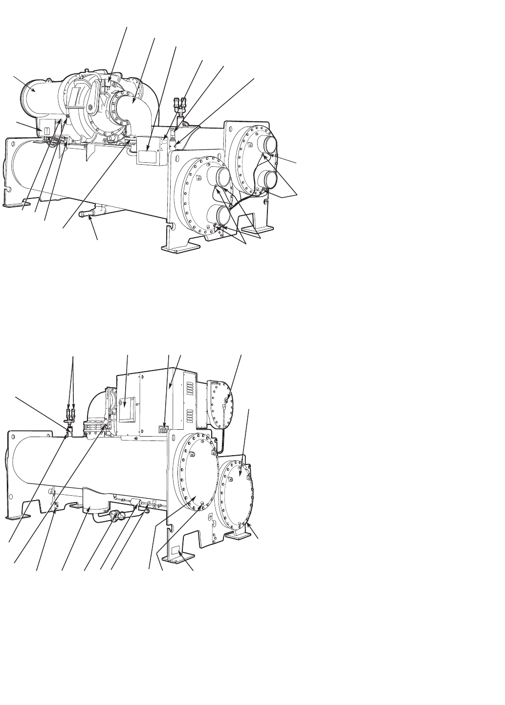
CHILLER FAMILIARIZATION
(Fig. 1 and 2)
Chiller Information Nameplate — The information
nameplate is located on the right side of the chiller control
panel.
System Components — The components include the
cooler and condenser heat exchangers in separate vessels,
motor-compressor, lubrication package, control panel, and mo-
tor starter. All connections from pressure vessels have external
threads to enable each component to be pressure tested with a
threaded pipe cap during factory assembly.
Cooler — This vessel (also known as the evaporator) is lo-
cated underneath the compressor. The cooler is maintained at
lower temperature/pressure so evaporating refrigerant can re-
move heat from water flowing through its internal tubes.
Condenser — The condenser operates at a higher
temperature/pressure than the cooler and has water flowing
through its internal tubes in order to remove heat from the
refrigerant.
Motor-Compressor — This component maintains sys-
tem temperature and pressure differences and moves the heat-
carrying refrigerant from the cooler to the condenser.
Control Panel — The control panel is the user interface
for controlling the chiller. It regulates the chiller’s capacity as
required to maintain proper leaving chilled water temperature.
The control panel:
• registers cooler, condenser, and lubricating system
pressures
• shows chiller operating condition and alarm shutdown
conditions
• records the total chiller operating hours
• sequences chiller start, stop, and recycle under micropro-
cessor control
• displays status of motor starter
• provides access to other CCN (Carrier Comfort Net-
work) devices and energy management systems
• Languages pre-installed at factory include: English, Chi-
nese, Japanese, and Korean (ICVC only).
• International language translator (ILT) is available for
conversion of extended ASCII characters (ICVC only).
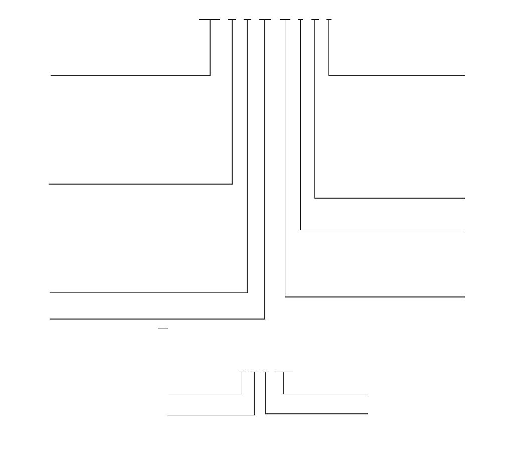
19XRV 52 51 473 DG H 64 –
19XR- — High Efficiency Hermetic
Centrifugal Liquid Chiller
19XRV — High Efficiency Hermetic
Centrifugal Liquid Chiller with
Variable Frequency Drive
Unit-Mounted
Condenser Size
10-12 (Frame 1 XR)
15-17 (Frame 1 XR)
20-22 (Frame 2 XR)
30-32 (Frame 3 XR)
35-37 (Frame 3 XR)
40-42 (Frame 4 XR)
45-47 (Frame 4 XR)
50-52 (Frame 5 XR)
55-57 (Frame 5 XR)
60-62 (Frame 6 XR)
65-67 (Frame 6 XR)
70-72 (Frame 7 XR)
75-77 (Frame 7 XR)
80-82 (Frame 8 XR)
85-87 (Frame 8 XR)
Special Order Indicator
– — Standard
S — Special Order
Motor Voltage Code
Code Volts-Phase-Hertz
60 — 200-3-60
61 — 230-3-60
62 — 380-3-60
63 — 416-3-60
64 — 460-3-60
65 — 575-3-60
66 — 2400-3-60
67 — 3300-3-60
68 — 4160-3-60
69 — 6900-3-60
50 — 230-3-50
51 — 346-3-50
52 — 400-3-50
53 — 3000-3-50
54 — 3300-3-50
55 — 6300-3-50
Compressor Code
(First Digit Indicates Compressor Frame Size)*
Motor Efficiency Code
H — High Efficiency
S — Standard Efficiency
Motor Code
BD CD DB EH
BE CE DC EJ
BF CL DD EK
BG CM DE EL
BH CN DF EM
CP DG EN
CQ DH EP
DJ
27 99 Q 59843
Week of Year
Year of Manufacture
Unique Number
Place of Manufacture
MODEL NUMBER NOMENCLATURE
SERIAL NUMBER BREAKDOWN
Cooler Size
10-12 (Frame 1 XR)
15-17 (Frame 1 XR)
20-22 (Frame 2 XR)
30-32 (Frame 3 XR)
35-37 (Frame 3 XR)
40-42 (Frame 4 XR)
45-47 (Frame 4 XR)
50-52 (Frame 5 XR)
5A (Frame 5 XR)
5B (Frame 5 XR)
5C (Frame 5 XR)
55-57 (Frame 5 XR)
5F (Frame 5 XR)
5G (Frame 5 XR)
5H (Frame 5 XR)
60-62 (Frame 6 XR)
65-67 (Frame 6 XR)
70-72 (Frame 7 XR)
75-77 (Frame 7 XR)
80-82 (Frame 8 XR)
85-87 (Frame 8 XR)
*Second digit will be a letter (example 4G3)
on units equipped with split ring diffuser.
Fig. 1 — 19XR Identification
6
34
18 19 20 21 22
23
31 30 29 28 27 26 25 24
32
33 24
1
2
3
5
6
4
11
12
13
16
15 14
17
7
9
10
8
Fig. 2 — Typical 19XR Components
LEGEND
1—Guide Vane Actuator
2—Suction Elbow
3—Chiller Visual Controller/ International Chiller
Visual Control (CVC/ICVC)
4—Chiller Identification Nameplate
5—Cooler, Auto Reset Relief Valves
6—Cooler Pressure Transducer
7—Condenser In/Out Temperature Thermistors
8—Condenser Waterflow Device (ICVC Inputs
available)
9—Cooler In/Out Temperature Thermistors
10 —Cooler Waterflow Device (ICVC Inputs avail-
able)
11 —Refrigerant Charging Valve
12 —Typical Flange Connection
13 —Oil Drain Charging Valve
14 —Oil Level Sight Glasses
15 —Refrigerant Oil Cooler (Hidden)
16 —Auxiliary Power Panel
17 —Compressor Motor Housing
LEGEND
18 —Condenser Auto. Reset Relief Valves
19 —Compressor Motor Circuit Breaker
20 —Solid-State Starter Control Display
21 —Unit-Mounted Starter (Optional)
Solid-State Starter Shown
22 —Motor Sight Glass
23 —Cooler Return-End Waterbox Cover
24 —ASME Nameplate (One Hidden)
25 —Typical Waterbox Drain Port
26 —Condenser Return-End Waterbox Cover
27 —Refrigerant Moisture/Flow Indicator
28 —Refrigerant Filter/Drier
29 —Liquid Line Isolation Valve (Optional)
30 —Linear Float Valve Chamber
31 —Vessel Take-Apart Connector
32 —Discharge Isolation Valve (Optional)
33 —Pumpout Valve
34 —Condenser Pressure Transducer
REAR VIEW
FRONT VIEW
7
Factory-Mounted Starter or Variable Fre-
quency Drive (Optional) — The starter allows for the
proper start and disconnect of electrical energy for the com-
pressor-motor, oil pump, oil heater, and control panel.
Storage Vessel (Optional) — There are 2 sizes of
storage vessels available. The vessels have double relief valves,
a magnetically-coupled dial-type refrigerant level gage, a
one-inch FPT drain valve, and a 1/2-in. male flare vapor con-
nection for the pumpout unit.
NOTE: If a storage vessel is not used at the jobsite, factory-
installed isolation valves on the chiller may be used to isolate
the chiller charge in either the cooler or condenser. An optional
pumpout system is used to transfer refrigerant from vessel to
vessel.
REFRIGERATION CYCLE
The compressor continuously draws refrigerant vapor from
the cooler at a rate set by the amount of guide vane opening or
compressor speed (19XRV only). As the compressor suction
reduces the pressure in the cooler, the remaining refrigerant
boils at a fairly low temperature (typically 38 to 42 F [3 to
6 C]). The energy required for boiling is obtained from the wa-
ter flowing through the cooler tubes. With heat energy re-
moved, the water becomes cold enough to use in an air condi-
tioning circuit or for process liquid cooling.
After taking heat from the water, the refrigerant vapor is
compressed. Compression adds still more heat energy, and the
refrigerant is quite warm (typically 98 to 102 F [37 to 40 C])
when it is discharged from the compressor into the condenser.
Relatively cool (typically 65 to 90 F [18 to 32 C]) water
flowing into the condenser tubes removes heat from the refrig-
erant and the vapor condenses to liquid.
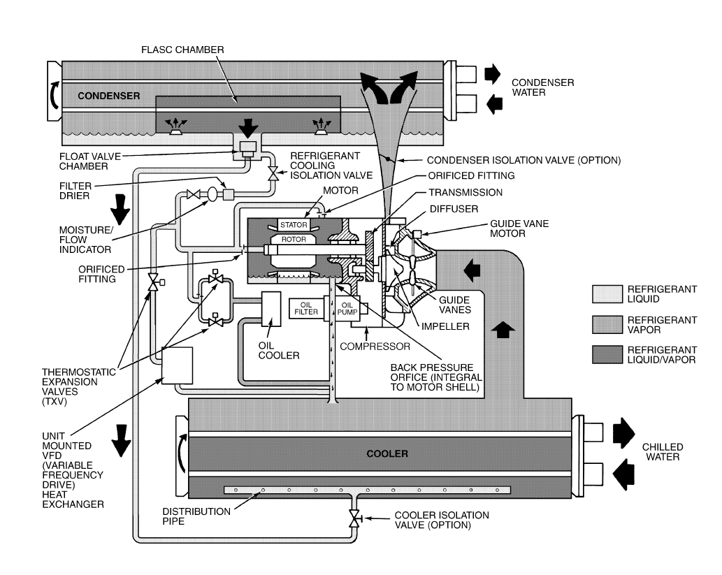
The liquid refrigerant passes through orifices into the
FLASC (Flash Subcooler) chamber (Fig. 3). Since the FLASC
chamber is at a lower pressure, part of the liquid refrigerant
flashes to vapor, thereby cooling the remaining liquid. The
FLASC vapor is recondensed on the tubes which are cooled by
entering condenser water. The liquid drains into a float cham-
ber between the FLASC chamber and cooler. Here a float valve
forms a liquid seal to keep FLASC chamber vapor from enter-
ing the cooler. When liquid refrigerant passes through the
valve, some of it flashes to vapor in the reduced pressure on the
cooler side. In flashing, it removes heat from the remaining liq-
uid. The refrigerant is now at a temperature and pressure at
which the cycle began.
MOTOR AND LUBRICATING OIL
COOLING CYCLE
The motor and the lubricating oil are cooled by liquid re-
frigerant taken from the bottom of the condenser vessel
(Fig. 3). Refrigerant flow is maintained by the pressure differ-
ential that exists due to compressor operation. After the refrig-
erant flows past an isolation valve, an in-line filter, and a sight
glass/moisture indicator, the flow is split between the motor
cooling and oil cooling systems.
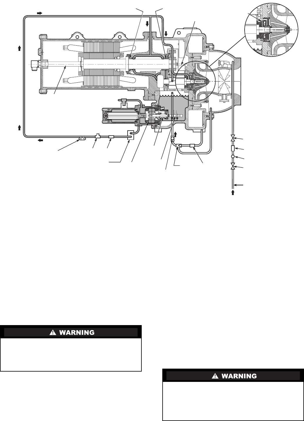
Fig. 3 — Refrigerant Motor Cooling and Oil Cooling Cycles
8
Flow to the motor cooling system passes through an orifice
and into the motor. Once past the orifice, the refrigerant is
directed over the motor by a spray nozzle. The refrigerant
collects in the bottom of the motor casing and is then drained
back into the cooler through the motor refrigerant drain line.
An orifice (in the motor shell) maintains a higher pressure in
the motor shell than in the cooler. The motor is protected by a
temperature sensor imbedded in the stator windings. An
increase in motor winding temperature past the motor override
set point overrides the temperature capacity control to hold,
and if the motor temperature rises 10° F (5.5° C) above this set
point, closes the inlet guide vanes. If the temperature rises
above the safety limit, the compressor shuts down.
Refrigerant that flows to the oil cooling system is regulated
by thermostatic expansion valves (TXVs). The TXVs regulate
flow into the oil/refrigerant plate and frame-type heat exchang-
er (the oil cooler in Fig. 3). The expansion valve bulbs control
oil temperature to the bearings. The refrigerant leaving the oil
cooler heat exchanger returns to the chiller cooler.
VFD COOLING CYCLE
The unit-mounted variable frequency drive (VFD) is cooled
in a manner similar to the motor and lubricating oil cooling
cycle (Fig. 3).
If equipped with a unit-mounted VFD, the refrigerant line
that feeds the motor cooling and oil cooler also feeds the heat
exchanger on the unit-mounted VFD. Refrigerant is metered
through a thermostatic expansion valve (TXV). To maintain
proper operating temperature in the VFD, the TXV bulb is
mounted to the heat exchanger to regulate the flow of refriger-
ant. The refrigerant leaving the heat exchanger returns to the
cooler.
LUBRICATION CYCLE
Summary — The oil pump, oil filter, and oil cooler make
up a package located partially in the transmission casing of the
compressor-motor assembly. The oil is pumped into a filter
assembly to remove foreign particles and is then forced into an
oil cooler heat exchanger where the oil is cooled to proper
operational temperatures. After the oil cooler, part of the flow
is directed to the gears and the high speed shaft bearings; the
remaining flow is directed to the motor shaft bearings. Oil
drains into the transmission oil sump to complete the cycle
(Fig. 4).
Details — Oil is charged into the lubrication system through
a hand valve. Two sight glasses in the oil reservoir permit oil
level observation. Normal oil level is between the middle of the
upper sight glass and the top of the lower sight glass when the
compressor is shut down. The oil level should be visible in at
least one of the 2 sight glasses during operation. Oil sump tem-
perature is displayed on the CVC/ICVC (Chiller Visual Con-
troller/International Chiller Visual Controller) default screen.
During compressor operation, the oil sump temperature ranges
between 125 to 150 F (52 to 66 C).
The oil pump suction is fed from the oil reservoir. An oil
pressure relief valve maintains 18 to 25 psid (124 to172 kPad)
differential pressure in the system at the pump discharge. This
differential pressure can be read directly from the CVC/ICVC
default screen. The oil pump discharges oil to the oil filter as-
sembly. This filter can be closed to permit removal of the filter
without draining the entire oil system (see Maintenance sec-
tions, pages 71 to 75, for details). The oil is then piped to the oil
cooler heat exchanger. The oil cooler uses refrigerant from the
condenser as the coolant. The refrigerant cools the oil to a tem-
perature between 120 and 140 F (49 to 60 C).
As the oil leaves the oil cooler, it passes the oil pressure
transducer and the thermal bulb for the refrigerant expansion
valve on the oil cooler. The oil is then divided. Part of the oil
flows to the thrust bearing, forward pinion bearing, and gear
spray. The rest of the oil lubricates the motor shaft bearings and
the rear pinion bearing. The oil temperature is measured in the
bearing housing as it leaves the thrust and forward journal
bearings. The oil then drains into the oil reservoir at the base of
the compressor. The PIC II (Product Integrated Control II)
measures the temperature of the oil in the sump and maintains
the temperature during shutdown (see Oil Sump Temperature
Control section, page 36). This temperature is read on the
CVC/ICVC default screen.
During the chiller start-up, the PIC II energizes the oil pump
and provides 45 seconds of pre-lubrication to the bearings after
pressure is verified before starting the compressor. During
shutdown, the oil pump will run for 60 seconds to post-
lubricate after the compressor shuts down. The oil pump can
also be energized for testing purposes during a Control Test.
Ramp loading can slow the rate of guide vane opening to
minimize oil foaming at start-up. If the guide vanes open
quickly, the sudden drop in suction pressure can cause any re-
frigerant in the oil to flash. The resulting oil foam cannot be
pumped efficiently; therefore, oil pressure falls off and lubrica-
tion is poor. If oil pressure falls below 15 psid (103 kPad) dif-
ferential, the PIC II will shut down the compressor.
If the controls are subject to a power failure that lasts more
than 3 hours, the oil pump will be energized periodically when
the power is restored. This helps to eliminate refrigerant that
has migrated to the oil sump during the power failure. The con-
trols energize the pump for 60 seconds every 30 minutes until
the chiller is started.
Oil Reclaim System — The oil reclaim system returns
oil lost from the compressor housing back to the oil reservoir
by recovering the oil from 2 areas on the chiller. The guide
vane housing is the primary area of recovery. Oil is also recov-
ered by skimming it from the operating refrigerant level in the
cooler vessel.
PRIMARY OIL RECOVERY MODE — Oil is normally re-
covered through the guide vane housing on the chiller. This is
possible because oil is normally entrained with refrigerant in
the chiller. As the compressor pulls the refrigerant up from the
cooler into the guide vane housing to be compressed, the oil
normally drops out at this point and falls to the bottom of the
guide vane housing where it accumulates. Using discharge gas
pressure to power an eductor, the oil is drawn from the housing
and is discharged into the oil reservoir.
SECONDARY OIL RECOVERY METHOD — The sec-
ondary method of oil recovery is significant under light load
conditions, when the refrigerant going up to the compressor
suction does not have enough velocity to bring oil along. Under
these conditions, oil collects in a greater concentration at the
top level of the refrigerant in the cooler. This oil and refrigerant
mixture is skimmed from the side of the cooler and is then
drawn up to the guide vane housing. There is a filter in this line.
Because the guide vane housing pressure is much lower than
the cooler pressure, the refrigerant boils off, leaving the oil be-
hind to be collected by the primary oil recovery method.
9
STARTING EQUIPMENT
The 19XR requires a motor starter to operate the centrifugal
hermetic compressor motor, the oil pump, and various auxilia-
ry equipment. The starter is the main field wiring interface for
the contractor.
See Carrier Specification Z-415 for specific starter require-
ments, Z-416 for free-standing VFD requirements and Z-417
for unit-mounted VFD requirements. All starters must meet
these specifications in order to properly start and satisfy me-
chanical safety requirements. Starters may be supplied as sepa-
rate, free-standing units or may be mounted directly on the
chiller (unit mounted) for low voltage units only.
Three separate circuit breakers are inside the starter. Circuit
breaker CB1 is the compressor motor circuit breaker. The dis-
connect switch on the starter front cover is connected to this
breaker. Circuit breaker CB1 supplies power to the compressor
motor.
Circuit breaker CB2 supplies power to the control panel, oil
heater, and portions of the starter controls.
Circuit breaker CB3 supplies power to the oil pump. Both
CB2 and CB3 are wired in parallel with CB1 so that power is
supplied to them if the CB1 disconnect is open.
All starters must include a Carrier control module called the
Integrated Starter Module (ISM), excluding the Benshaw
solid-state starters. This module controls and monitors all as-
pects of the starter. See the Controls section on page 10 for ad-
ditional ISM information. All starter replacement parts are sup-
plied by the starter manufacturer excluding the ISM (contact
Carrier’s Replacement Component Division [RCD]).
Unit-Mounted Solid-State Starter (Optional) —
The 19XR chiller may be equipped with a solid-state, reduced-
voltage starter (Fig. 5 and 6). This starter’s primary function is
to provide on-off control of the compressor motor. This type of
starter reduces the peak starting torque, reduces the motor in-
rush current, and decreases mechanical shock. This capability
is summed up by the phrase “soft starting.” The solid-state
starter is available as a 19XR option (factory supplied and in-
stalled). The solid-state starters manufacturer name is located
inside the starter access door.
A solid-state, reduced-voltage starter operates by reducing
the starting voltage. The starting torque of a motor at full volt-
age is typically 125% to 175% of the running torque. When the
voltage and the current are reduced at start-up, the starting
torque is reduced as well. The object is to reduce the starting
voltage to just the voltage necessary to develop the torque re-
quired to get the motor moving. The voltage is reduced by sili-
con controlled rectifiers (SCRs). The voltage and current are
then ramped up in a desired period of time. Once full voltage is
reached, a bypass contactor is energized to bypass the SCRs.
The main circuit breaker (CB1) on the front of the starter
disconnects the main motor current only. Power is still
energized for the other circuits. Two more circuit breakers
inside the starter must be turned off to disconnect power to
the oil pump, PIC II controls, and oil heater.
When voltage is supplied to the solid-state circuitry (CB1
is closed), the heat sinks in the starter as well as the wires
leading to the motor and the motor terminal are at line volt-
age. Do not touch the heat sinks, power wiring, or motor
terminals while voltage is present or serious injury will
result.
REAR MOTOR
BEARING
ISOLATION
VALVE
SIGHT
GLASS
FILTER
ISOLATION
VALVE
FILTEREDUCTOR
OIL
PUMP
TXV BULB PRESSURE
TRANSDUCER
ISOLATION
VALVE
OIL
COOLER OIL PUMP
MOTOR
OIL
HEATER
MOTOR
COOLING LINE
LABYRINTH
GAS LINE
FWD MOTOR
BEARING
OIL SUPPLY TO
FORWARD HIGH
SPEED BEARING
SIGHT GLASS
OIL SKIMMER LINE
Fig. 4 — Lubrication System
10
There is a display on the front of the Benshaw, Inc., solid-
state starters that is useful for troubleshooting and starter
checkout. The display indicates:
•voltage to the SCRs
•SCR control voltage
•power indication
•proper phasing for rotation
•start circuit energized
•over-temperature
•ground fault
•current unbalance
•run state
•software configuration
The starter is further explained in the Check Starter and
Troubleshooting Guide sections, pages 54 and 76.
Unit-Mounted Wye-Delta Starter (Optional) —
The 19XR chiller may be equipped with a wye-delta starter
mounted on the unit. This starter is used with low-voltage mo-
tors (under 600 v). It reduces the starting current inrush by con-
necting each phase of the motor windings into a wye configu-
ration. This occurs during the starting period when the motor is
accelerating up to speed. Once the motor is up to speed, the
starter automatically connects the phase windings into a delta
configuration. Starter control, monitoring, and motor protec-
tion is provided by Carrier’s Integrated Starter Module (ISM).
Unit-Mounted VFD (Optional) — The 19XRV unit
will be equipped with a variable frequency drive motor control-
ler mounted on the unit. See Fig. 7 and 8. This VFD is used
with low voltage motors between 380 and 480 VAC. It reduces
the starting current inrush by controlling the voltage and fre-
quency to the compressor motor. Once the motor has accelerat-
ed to minimum speed the PIC II modulates the compressor
speed and guide vane position to control chilled water tempera-
ture. The VFD is further explained in the Controls section and
Troubleshooting Guide section, pages 10 and 76.
There is a separate display located on the unit-mounted
VFD. Operational parameters and fault codes are displayed rel-
ative to the drive. Refer to specific drive literature along with
troubleshooting sections. The display is also the interface for
entering specific chiller operational parameters. These parame-
ters have been preprogrammed at the factory. An adhesive
backed label on the inside of the drive has been provided for
verification of the specific job parameters. See Initial Start-Up
Checklist section for details.
CONTROLS
Definitions
ANALOG SIGNAL — An analog signal varies in proportion
to the monitored source. It quantifies values between operating
limits. (Example: A temperature sensor is an analog device be-
cause its resistance changes in proportion to the temperature,
generating many values.)
DISCRETE SIGNAL — A discrete signal is a 2-position rep-
resentation of the value of a monitored source. (Example: A
switch produces a discrete signal indicating whether a value is
above or below a set point or boundary by generating an on/off,
high/low, or open/closed signal.)
5
1
2
3
6
4
7
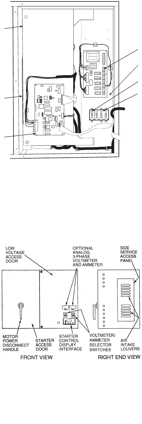
LEGEND
Fig. 5 — Solid-State Starter Box,
Internal View
1—RediStart MICRO™ Input/Output Card
2—Fuses 1-4 (Hidden, not depicted)
3—Circuit Breaker 2 (CB2): Machine Control and Heater Power
4—Circuit Breaker 3 (CB3): Oil Pump Power
5—RediStart MICRO Central Processing Unit Card (CPU)
6—RediStart MICRO Power Card (hidden, not depicted)
7—RediStart MICRO Bypass Card (hidden, not depicted)
Fig. 6 — Typical Starter External View
(Solid-State Starter Shown)
11
General — The 19XR hermetic centrifugal liquid chiller
contains a microprocessor-based control center that monitors
and controls all operations of the chiller (see Fig. 9). The
microprocessor control system matches the cooling capacity of
the chiller to the cooling load while providing state-of-the-art
chiller protection. The system controls cooling load within the
set point plus the deadband by sensing the leaving chilled water
or brine temperature and regulating the inlet guide vane via a
mechanically linked actuator motor. The guide vane is a vari-
able flow pre-whirl assembly that controls the refrigeration ef-
fect in the cooler by regulating the amount of refrigerant vapor
flow into the compressor. An increase in guide vane opening
increases capacity. A decrease in guide vane opening decreases
capacity. The microprocessor-based control center protects the
chiller by monitoring the digital and analog inputs and execut-
ing capacity overrides or safety shutdowns, if required.
PIC II System Components — The chiller control
system is called the PIC II (Product Integrated Control II). See
Table 1. The PIC II controls the operation of the chiller by
monitoring all operating conditions. The PIC II can diagnose a
problem and let the operator know what the problem is and
what to check. It promptly positions the guide vanes to main-
tain leaving chilled water temperature. It can interface with
auxiliary equipment such as pumps and cooling tower fans to
turn them on when required. It continually checks all safeties to
prevent any unsafe operating condition. It also regulates the oil
heater while the compressor is off and regulates the hot gas by-
pass valve, if installed. The PIC II controls provide critical pro-
tection for the compressor motor and controls the motor starter.
SPEED
VOLTS
AMPS
Hz
Kw
TORQUE
Password
RUNNING
REMOTE
JOG
AUTO
FORWARD
REVERSE
PROGRAM
PRO-
GRAM
Forward
Reverse
ENTER
RUN
JOB
AUTO
MAN
SPEED
VOLTS
AMPS
Hz
Kw
TORQUE
Password
RUNNING
REMOTE
JOG
AUTO
FORWARD
REVERSE
PROGRAM
PROGRAM
Forward
Reverse
ENTER
RUN
JOB
AUTO
MAN
MANUAL RESET
OPTIONAL
METER
PACKAGE
SPEED
VOLTS
AMPS
Hz
Kw
TORQUE
Password
RUNNING
REMOTE
JOG
AUTO
FORWARD
REVERSE
PROGRAM
PROGRAM
Forward
Reverse
ENTER
RUN
JOB
AUTO
MAN
DANGER
HIGH VOLTAGE
+-
INITIAL DC BUS
MEASUREMENT
POINT
DC BUS BAR
MEASUREMENT
POINT
+
-
VFD
MODULE
COOLING LINES
COMPRESSOR
MOTOR
DISCONNECT TXV
CONTROL
AND OIL
HEATER
DISCONNECT
OIL PUMP
DISCONNECT
INTEGRATED
STARTER
MODULE
(ISM)
LINE
LOAD
Fig. 7 — Variable Frequency Drive (VFD)
Fig. 8 — Variable Frequency Drive (VFD) Starter Internal View

12
FITTING (HIDDEN) PANEL ACTUATOR CABLE PANEL CABLE
WATER
SENSOR
CABLES
WATER
SENSOR
CABLES
COOLER
PRESSURE
TRANSDUCER
CONNECTION
CONDENSER
PRESSURE
CABLE
SCHRADER
FITTING (HIDDEN)
CONDENSER
PRESSURE
TRANSDUCER
CONNECTION
CONDENSER
SERVICE
VALVE
COMPRESSOR
DISCHARGE
ELBOW JOINTS
MOTOR WINDING
TEMPERATURE
CABLE
DISCHARGE
ISOLATION
VALVE
(OPTIONAL)
TOP VIEW
COMPRESSOR DETAIL
Fig. 9 — 19XR Controls and Sensor Locations

13
The PIC II can interface with the Carrier Comfort Network
(CCN) if desired. It can communicate with other PIC I or PIC
II equipped chillers and other CCN devices.
The PIC II consists of 3 modules housed inside 3 major
components. The component names and corresponding control
voltages are listed below (also see Table 1):
•control panel
— all extra low-voltage wiring (24 v or less)
•power panel
— 230 or 115 v control voltage (per job requirement)
— up to 600 v for oil pump power
•starter cabinet
— chiller power wiring (per job requirement)
Table 1 — Major PIC II Components and
Panel Locations*
*See Fig. 8-13.
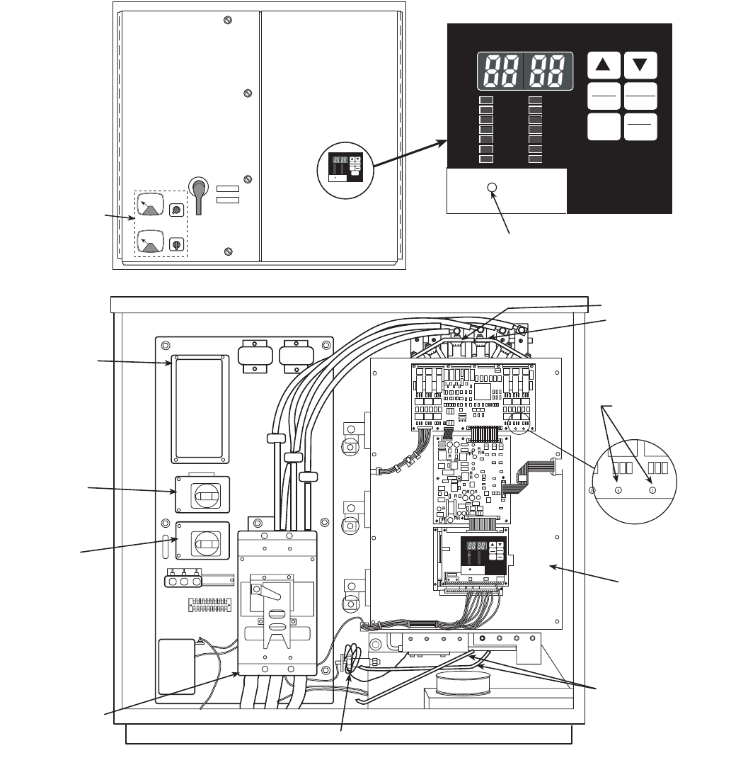
CHILLER VISUAL CONTROLLER (CVC) — The CVC is
the “brain” of the PIC II. This module contains all the operating
software needed to control the chiller. The CVC is mounted to
the control panel (Fig. 12) and is the input center for all local
chiller set points, schedules, configurable functions, and op-
tions. The CVC has a stop button, an alarm light, four buttons
for logic inputs, and a backlight display. The backlight will au-
tomatically turn off after 15 minutes of non-use. The functions
of the four buttons or “softkeys” are menu driven and are
shown on the display directly above the softkeys.
The viewing angle of the CVC can be adjusted for optimum
viewing. Remove the 2 bolts connecting the control panel to
the brackets attached to the cooler. Place them in one of the
holes to pivot the control panel forward to backward to change
the viewing angle. See Fig. 12. To change the contrast of the
display, access the adjustment on the back of the CVC. See
Fig. 12.
INTERNATIONAL CHILLER VISUAL CONTROLLER
(ICVC) — Incorporates all of the functions and operating soft-
ware of the CVC with the added feature of 4 factory pro-
grammed languages:
English (default)
Chinese
Japanese
Korean
NOTE: Pressing any one of the four softkey buttons will acti-
vate the backlight display without implementing a softkey
function.
INTEGRATED STARTER MODULE (ISM) — This mod-
ule is located in the starter cabinet. This module initiates com-
mands from the CVC/ICVC for starter functions such as start-
ing and stopping the compressor, condenser, chilled water
pumps, tower fan, spare alarm contacts, and the shunt trip. The
ISM monitors starter inputs such as line voltage, motor current,
ground fault, remote start contact, spare safety, condenser high
pressure, oil pump interlock, starter 1M, and run contacts. The
ISM contains logic capable of safety shutdown. It shuts down
the chiller if communications with the CVC/ICVC are lost.
The ISM can also act as the interface for PIC II to the VFD
controller.
CHILLER CONTROL MODULE (CCM) — This module is
located in the control panel. The CCM provides the input and
outputs necessary to control the chiller. This module monitors
refrigerant pressure, entering and leaving water temperatures,
and outputs control for the guide vane actuator, oil heaters, and
oil pump. The CCM is the connection point for optional de-
mand limit, chilled water reset, remote temperature reset, re-
frigerant leak sensor and motor kilowatt output.
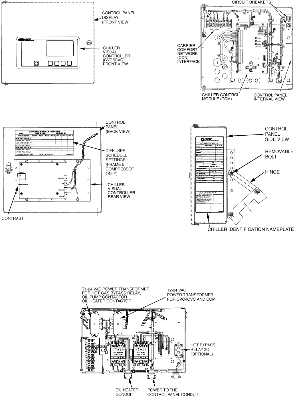
OIL HEATER CONTACTOR (1C) — This contactor is lo-
cated in the power panel (Fig. 13) and operates the heater at
either 115 or 230 v. It is controlled by the PIC II to maintain oil
temperature during chiller shutdown. The XR4 with split ring
diffuser has a line voltage oil heater. Refer to the control panel
wiring schematic.
OIL PUMP CONTACTOR (2C) — This contactor is located
in the power panel. It operates all 200 to 575-v oil pumps.
The PIC II energizes the contactor to turn on the oil pump as
necessary.
HOT GAS BYPASS CONTACTOR RELAY (3C)
(Optional) — This relay, located in the power panel, controls
the opening of the hot gas bypass valve. The PIC II energizes
the relay during low load, high lift conditions.
CONTROL TRANSFORMERS (T1, T2) — These transform-
ers convert incoming control voltage to 24 vac power for the
3 power panel contactor relays, CCM, and CVC/ICVC.
OPTIONAL TRANSFORMER (T3) — This transformer pro-
vides control power to Dataport™/DataLINK™ modules.
PIC II COMPONENT PANEL LOCATION
Chiller Visual Controller (CVC/ICVC) and
Display
Control Panel
Integrated Starter Module (ISM) Starter Cabinet
Chiller Control Module (CCM) Control Panel
Oil Heater Contactor (1C) Power Panel
Oil Pump Contactor (2C) Power Panel
Hot Gas Bypass Relay (3C) (Optional) Power Panel
Control Transformers (T1, T2) Power Panel
Temperature Sensors See Fig. 9.
Pressure Transducers See Fig. 9.
Fig. 10 — Control Sensors (Temperature)
Fig. 11 — Control Sensors
(Pressure Transducers, Typical)
14
Fig. 12 — Control Panel
Fig. 13 — Power Panel

15
CVC/ICVC Operation and Menus (Fig. 14-20)
GENERAL
•The CVC/ICVC display automatically reverts to the
default screen after 15 minutes if no softkey activity
takes place and if the chiller is not in the pumpdown
mode (Fig. 14).
•If a screen other than the default screen is displayed on
the CVC/ICVC, the name of that screen is in the upper
right corner (Fig. 15).
•The CVC/ICVC may be set to display either English or
SI units. Use the CVC/ICVC configuration screen
(accessed from the Service menu) to change the units.
See the Service Operation section, page 45.
•Local Operation — The PIC II can be placed in local
operating mode by pressing the softkey. The
PIC II then accepts commands from the CVC/ICVC only
and uses the Local Time Schedule to determine chiller
start and stop times.
•CCN Operation — The PIC II can be placed in the CCN
operating mode by pressing the softkey. The PIC
II then accepts modifications from any CCN interface or
module (with the proper authority), as well as from the
CVC/ICVC. The PIC II uses the CCN time schedule to
determine start and stop times.
ALARMS AND ALERTS — An alarm shuts down the com-
pressor. An alert does not shut down the compressor, but it no-
tifies the operator that an unusual condition has occurred. An
alarm (*) or alert (!) is indicated on the STATUS screens on the
far right field of the CVC/ICVC display screen.
Alarms are indicated when the control center alarm light (!)
flashes. The primary alarm message is displayed on the default
screen. An additional, secondary message and troubleshooting
information are sent to the ALARM HISTORY table.
When an alarm is detected, the CVC/ICVC default screen
will freeze (stop updating) at the time of alarm. The freeze en-
ables the operator to view the chiller conditions at the time of
alarm. The STATUS tables will show the updated information.
Once all alarms have been cleared (by pressing the
softkey), the default CVC/ICVC screen will return to normal
operation.
CVC/ICVC MENU ITEMS — To perform any of the opera-
tions described below, the PIC II must be powered up and have
successfully completed its self test. The self test takes place au-
tomatically, after power-up.
Press the softkey to view the list of menu struc-
tures: , , , and
.
•The STATUS menu allows viewing and limited calibra-
tion or modification of control points and sensors, relays
and contacts, and the options board.
•The SCHEDULE menu allows viewing and modification
of the local and CCN time schedules and Ice Build time
schedules.
•The SETPOINT menu allows set point adjustments, such
as the entering chilled water and leaving chilled water set
points.
•The SERVICE menu can be used to view or modify
information on the Alarm History, Control Test, Control
Algorithm Status, Equipment Configuration, ISM Starter
Configuration data, Equipment Service, Time and Date,
Attach to Network Device, Log Out of Network Device,
and CVC/ICVC Configuration screens.
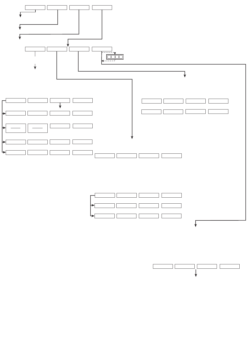
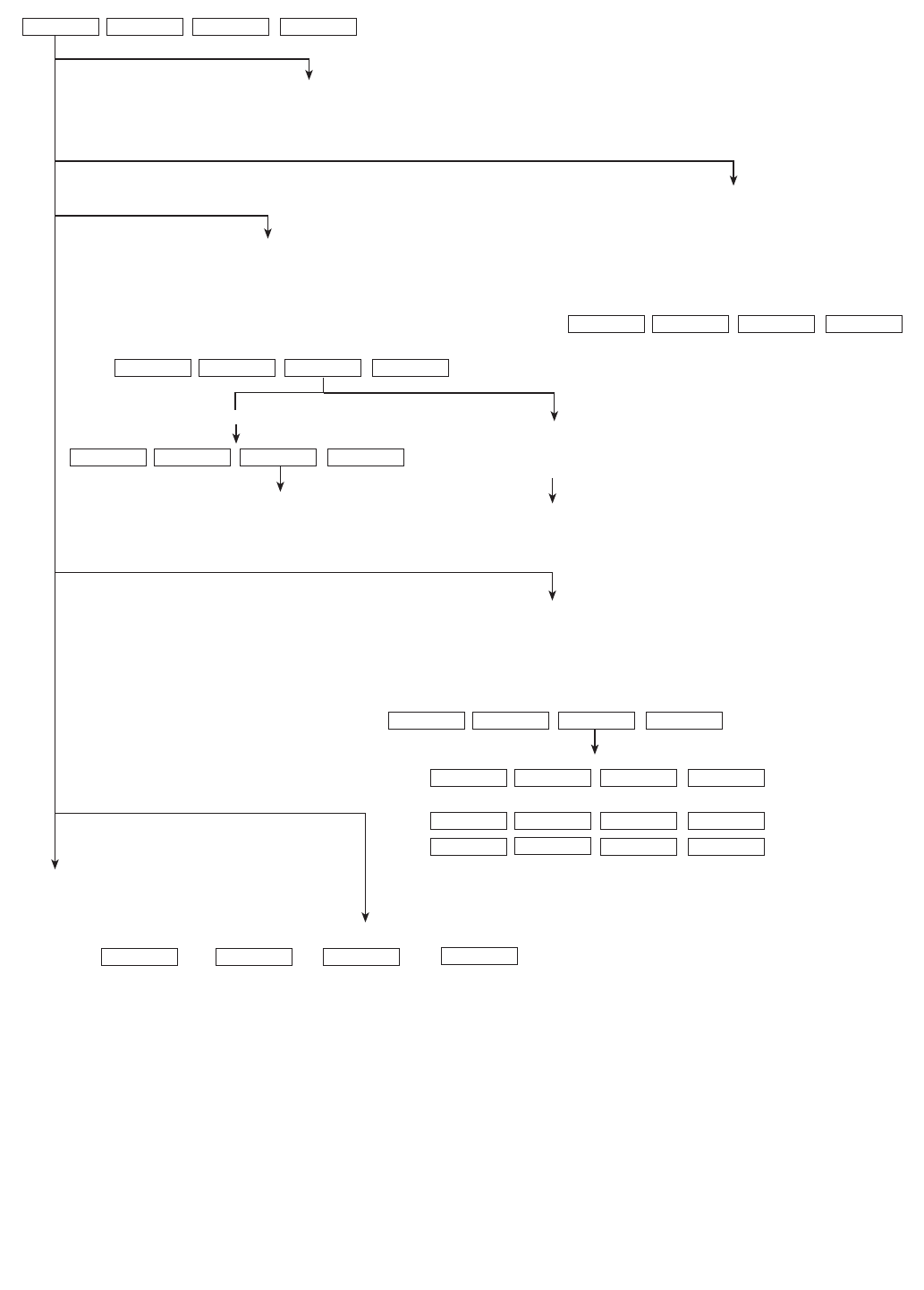
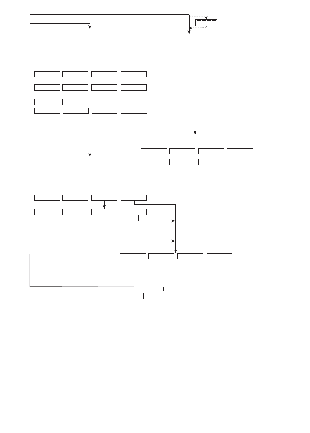
For more information on the menu structures, refer to
Fig. 17.
Press the softkey that corresponds to the menu structure to
be viewed: , , or
. To view or change parameters within any of these
menu structures, use the and softkeys
to scroll down to the desired item or table. Use the
softkey to select that item. The softkey choices that then appear
depend on the selected table or menu. The softkey choices and
their functions are described below.
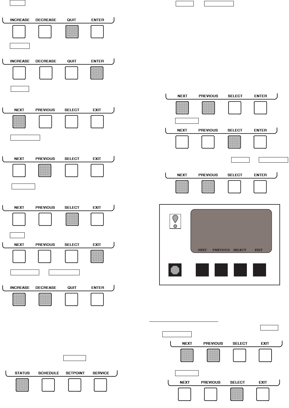
BASIC CVC/ICVC OPERATIONS (Using the Soft-
keys) — To perform any of the operations described below,
the PIC II must be powered up and have successfully complet-
ed its self test.
LOCAL
CCN
RESET
MENU
STATUS SCHEDULE SETPOINT
SERVICE
STATUS SCHEDULE SETPOINT
SERVICE NEXT PREVIOUSSELECT
RUNNING TEMP CONTROL
LEAVING CHILLED WATER 01-01-95 11:48
28.8 HOURS
CHW IN CHW OUT EVAP REF
CDW IN CDW OUT COND REF
OIL PRESS OIL TEMP AMPS %
CCN LOCAL RESET MENU
55.1 44.1 40.7
85.0 95.0 98.1
21.8 132.9 93
PRIMARY STATUS
MESSAGE
COMPRESSOR
ON TIME
DATE TIME
SOFT KEYS MENU
LINE
EACH KEY'S FUNCTION IS
DEFINED BY THE MENU DESCRIPTION
ON MENU LINE ABOVE
ALARM LIGHT
(ILLUMINATED
WHEN POWER ON)
STOP BUTTON
•
HOLD FOR ONE
SECOND TO STOP
•
•
BLINKS CONTINUOUSLY
ON FOR AN ALARM
BLINKS ONCE TO
CONFIRM A STOP
SECONDARY
STATUS
MESSAGE
CONTROL TEST
CONTROL ALGORITHM STATUS
EQUIPMENT CONFIGURATION
ISM (STARTER) CONFIGURATION DATA
EQUIPMENT SERVICE
TIME AND DATE
ATTACH TO NETWORK DEVICE
LOG OUT OF DEVICE
CVC CONFIGURATION
ALARM HISTORY
19XR_II SERVICE
Fig. 15 — CVC/ICVC Service Screen
Fig. 14 — CVC/ICVC Default Screen
16
•Press to leave the selected decision or field with-
out saving any changes.
•Press to leave the selected decision or field and
save changes.
•Press to scroll the cursor bar down in order to
highlight a point or to view more points below the cur-
rent screen.
•Press to scroll the cursor bar up in order to
highlight a point or to view points above the current
screen.
•Press to view the next screen level (high-
lighted with the cursor bar), or to override (if allowable)
the highlighted point value.
•Press to return to the previous screen level.
•Press or to change the high-
lighted point value.
TO VIEW STATUS (Fig. 16) — The status table shows the
actual value of overall chiller status such as CONTROL
MODE, RUN STATUS, AUTO CHILLED WATER RESET,
and REMOTE RESET SENSOR.
1. On the menu screen, press to view the list of
point status tables.
2. Press or to highlight the desired
status table. The list of tables is:
•MAINSTAT — Overall chiller status
•STARTUP — Status required to perform start-up of
chiller
•COMPRESS — Status of sensors related to the
compressor
•HEAT_EX — Status of sensors related to the heat
exchangers
•POWER — Status of motor input power
•ISM_STAT — Status of motor starter
•CVC_PSWD — Service menu password forcing
access screen
•ICVC_PSWD — Service menu password forcing
access screen
3. Press to view the desired point status table.
4. On the point status table, press or
until the desired point is displayed on the screen.
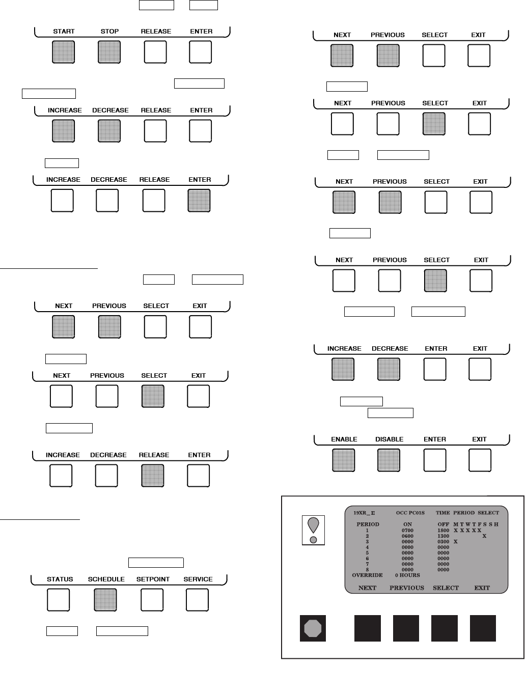
OVERRIDE OPERATIONS
To Override a Value or Status
1. From any point status screen, press or
to highlight the desired value.
2. Press to select the highlighted value. Then:
QUIT
ENTER
NEXT
PREVIOUS
SELECT
EXIT
INCREASE DECREASE
STATUS
NEXT PREVIOUS
SELECT
NEXT PREVIOUS
NEXT
PREVIOUS
SELECT
19XR_II MAINSTAT POINT STATUS
Control Mode
Run Status
Start Inhibit Timer
Occupied?
System Alert/Alarm
Chiller Start/Stop
Remote Start Contact
Temperature Reset
Control Point
Chilled Water Temp
Active Demand Limit
Average Line Current
OFF
Ready
0.0 Min
NO
NORMAL
STOP
Open
0.0 F
44.0 F
44.6 F
100%
0.0%
Fig. 16 — Example of Status Screen
17
•
CCN LOCAL RESET MENU
DEFAULT SCREEN
Start Chiller In CCN Control
Start Chiller in Local Control
Clear Alarms
STATUS SCHEDULE SETPOINT SERVICE
(SOFTKEYS)
Access Main Menu
List the
Status Tables
Display The Setpoint Table
(ENTER A 4-DIGIT PASSWORD) (VALUES SHOWN AT FACTORY DEFAULT)
List the Service Tables
• OCCPC01S – LOCAL TIME SCHEDULE
• OCCPC02S – ICE BUILD TIME SCHEDULE
• OCCPC03S – CCN TIME SCHEDULE
List the Schedules
1
ALARM HISTORY
CONTROL TEST
CONTROL ALGORITHM STATUS
EQUIPMENT CONFIGURATION
ISM (STARTER) CONFIG DATA
EQUIPMENT SERVICE
TIME AND DATE
ATTACH TO NETWORK DEVICE
LOG OUT OF DEVICE
CVC CONFIGURATION
ICVC CONFIGURATION
Base Demand Limit
• LCW Setpoint
• ECW Setpoint
• Ice Build Setpoint
• Tower Fan High Setpoint
EXIT
SELECT
PREVIOUS
NEXT
Select a Schedule
1
2
3
4
5
6
7
8
Override
ENABLE DISABLE
EXIT
SELECT
PREVIOUS
NEXT
Select a Time Period/Override
Modify a Schedule Time
ENTER EXIT
INCREASE DECREASE ENTER EXIT (ANALOG VALUES)
(DISCRETE VALUES)
Add/Eliminate a Day
111
Select a Status Table
NEXT PREVIOUS SELECT EXIT
START
ON
STOP
OFF
RELEASE ENTER
EXIT
NEXT PREVIOUS SELECT
ENTER
ENABLE DISABLE QUIT
DECREASE
INCREASE ENTER
RELEASE
Select a Modification Point
Modify a Discrete Point
Modify an Analog Point
Modify Control Options
• MAINSTAT
• STARTUP
• COMPRESS
• HEAT_EX
• POWER
• ISM_STAT
• CVC_PSWD
Modify the Setpoint
DECREASE
INCREASE QUIT ENTER
NEXT PREVIOUS SELECT EXIT
Select the Setpoint
•
NEXT PREVIOUS SELECT EXIT
SEE FIGURE 18
Fig. 17 — 19XR Chiller Display Menu Structure (CVC/ICVC)
18
•
NEXT PREVIOUS SELECT EXIT
SERVICE TABLE
Display Alarm History
(The table holds up to 25 alarms and
alerts with the most recent alarm
at the top of the screen.)
• CCM Thermistors
• CCM Pressure Transducers
• Pumps
• Discrete Outputs
• Guide Vane Actuator
• Diffuser Actuator
• Pumpdown/Lockout
• Terminate Lockout
• Guide Vane Calibration
CONTINUED
ON NEXT PAGE
CONTROL ALGORITHM STATUS
CONTROL TEST
ALARM HISTORY
List the Control Tests
NEXT PREVIOUS SELECT EXIT
Select a Test
List the Control Algorithm Status Tables
• CAPACITY (Capacity Control)
• OVERRIDE (Override Status)
• LL_MAINT (Lead Lag Status)
• ISM_HIST (ISM Alarm History)
• LOADSHED
• WSMDEFME (Water System Manager Control Status)
• OCCDEFCM (Time Schedule Status)
NEXT PREVIOUS SELECT EXIT
Select a Table
• NET_OPT
• BRODEF
• OCCEFCS
• HOLIDAYS
• CONSUME
• RUNTIME
(ANALOG VALUES)
(DISCRETE VALUES)
Select a Parameter
NEXT PREVIOUS SELECT EXIT
Modify a Parameter
ENTER
ENABLE DISABLE QUIT
DECREASE
INCREASE ENTER
QUIT
NEXT PREVIOUS SELECT EXIT
Select a Table
EQUIPMENT CONFIGURATION List the Equipment Configuration Tables
• CAPACITY (Capacity Control Algorithm)
• OVERRIDE (Override Status)
• LL_MAINT (LEADLAG Status)
• WSMDEFM2 (Water System Manager Control Status)
Maintenance Table Data
NEXT PREVIOUS SELECT EXIT
Data Select Table
OCCPC01S (Local Status)
OCCPC02S (CCN, ICE BUILD Status)
OCCPC03S (CCN Status)
OCCDEFM (Time Schedule Status)
ICVC CONFIGURATION
SELECT (USE ENTER) TO SCROLL DOWN
LID LANGUAGE
INCREASE DECREASE ENTER EXIT
Fig. 18 — 19XR Service Menu Structure
19
NEXT PREVIOUS SELECT EXIT
SERVICE MENU CONTINUED
FROM PREVIOUS PAGE
Select a Service Table
Select a Service Table Parameter
NEXT PREVIOUS SELECT EXIT
Modify a Service Table Parameter
(ANALOG VALUES)
(DISCRETE VALUES)
TIME AND DATE
Display Time and Date Table:
• To Modify — Current Time — Day of Week
— Current Date — Holiday Today
ATTACH TO NETWORK DEVICE
ENTER
DECREASE
INCREASE EXIT
ENTER
ENABLE DISABLE QUIT
DECREASE
INCREASE ENTER
QUIT
Select a Device
ATTACH
NEXT PREVIOUS SELECT
Modify Device Address
EXIT
INCREASE DECREASE ENTER
• Use to attach CVC to another CCN network or device
• Attach to "LOCAL" to enter this machine
• To upload new tables
Default Screen
MENU
RESET
CCN LOCAL
LOG OUT OF DEVICE
List Network Devices
• Local
• Device 1
• Device 2
• Device 3
• Device 4
• Device 5
• Device 6
• Device 7
• Device 8
• Device 9
Service Tables:
• OPTIONS
• SETUP1
• SETUP2
• LEADLAG
• RAMP_DEM
• TEMP_CTL
EQUIPMENT SERVICE
ISM (STARTER) CONFIG DATA
Service Tables:
• ISM (STARTER) CONFIG PASSWORD
• ISM_CONF
(ENTER A 4-DIGIT PASSWORD)
(VALUES SHOWN AT FACTORY DEFAULT)
4444
CVC CONFIGURATION
EXIT
INCREASE DECREASE ENTER
CVC Configuration Table
• To Modify — CVC CCN Address
— English (U.S. IMP.) or S.I. Metric Units
— Password
• To View — CVC Software Version
(last 2 digits of part number
indicate software version)
ENTER
NO
YES EXIT
(ANALOG VALUE)
(DISCRETE VALUE)
LEGEND
CCN —Carrier Comfort Network
CVC —Chiller Visual Controller
ICVC —International Chiller Visual Controller
ISM —Integrated Starter Module
PIC II —Product Integrated Control II
Fig. 18 — 19XR Service Menu Structure (cont)
20
For Discrete Points — Press or to se-
lect the desired state.
For Analog Points — Press or
to select the desired value.
3. Press to register the new value.
NOTE: When overriding or changing metric values, it is nec-
essary to hold down the softkey for a few seconds in order to
see a value change, especially on kilopascal values.
To Remove an Override
1. On the point status table press or
to highlight the desired value.
2. Press to access the highlighted value.
3. Press to remove the override and return the
point to the PIC II’s automatic control.
Override Indication — An override value is indicated by
“SUPVSR,” “SERVC,” or “BEST” flashing next to the point
value on the STATUS table.
TIME SCHEDULE OPERATION (Fig. 19)
1. On the Menu screen, press .
2. Press or to highlight the desired
schedule.
OCCPC01S — LOCAL Time Schedule
OCCPC02S — ICE BUILD Time Schedule
OCCPC03S — CCN Time Schedule
3. Press to view the desired time schedule.
4. Press or to highlight the desired
period or override to change.
5. Press to access the highlighted period or
override.
6. a. Press or to change the
time values. Override values are in one-hour
increments, up to 4 hours.
b. Press to select days in the day-of-week
fields. Press to eliminate days from the
period.
START STOP
INCREASE
DECREASE
ENTER
NEXT PREVIOUS
SELECT
RELEASE
SCHEDULE
NEXT PREVIOUS
SELECT
NEXT PREVIOUS
SELECT
INCREASE DECREASE
ENABLE
DISABLE
Fig. 19 — Example of Time Schedule
Operation Screen
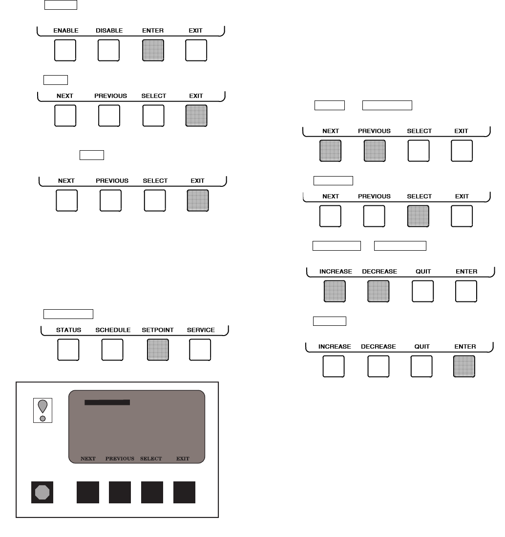
21
7. Press to register the values and to move hori-
zontally (left to right) within a period.
8. Press to leave the period or override.
9. Either return to Step 4 to select another period or over-
ride, or press again to leave the current time
schedule screen and save the changes.
10. The Holiday Designation (HOLIDEF table) may be
found in the Service Operation section, page 45. The
month, day, and duration for the holiday must be
assigned. The Broadcast function in the BRODEF
table also must be enabled for holiday periods to
function.
TO VIEW AND CHANGE SET POINTS (Fig. 20)
1. To view the SETPOINT table, from the MENU screen
press .
2. There are 5 set points on this screen: BASE DEMAND
LIMIT, LCW SETPOINT (leaving chilled water set
point), ECW SETPOINT (entering chilled water set
point), ICE BUILD SETPOINT, and TOWER FAN
HIGH SETPOINT. Only one of the chilled water set
points can be active at one time. The set point that is
active is determined from the SERVICE menu. See the
Service Operation section, page 45. The ice build (ICE
BUILD) function is also activated and configured from
the SERVICE menu.
3. Press or to highlight the desired
set point entry.
4. Press to modify the highlighted set point.
5. Press or to change the select-
ed set point value.
6. Press to save the changes and return to the pre-
vious screen.
SERVICE OPERATION — To view the menu-driven pro-
grams available for Service Operation, see Service Operation
section, page 45. For examples of CVC/ICVC display screens,
see Table 2.
ENTER
EXIT
EXIT
SETPOINT
NEXT PREVIOUS
SELECT
INCREASE DECREASE
ENTER
19XR_II SETPOINT SELECT
SETPOINT
Base Demand Limit
Control Point
LCW Setpoint
ECW Setpoint
ICE BUILD Setpoint
Tower Fan High Setpoint
100%
50.0 F
60.0 F
40.0 F
85.0 F
Fig. 20 — Example of Set Point Screen

22
Table 2 — CVC/ICVC Display Data
1. Only 12 lines of information appear on the chiller display screen
at any one time. Press the or softkey to
highlight a point or to view items below or above the current
screen. Press the softkey twice to page forward; press
the softkey twice to page back.
2. To access the information shown in Examples 10 through 22,
enter your 4-digit password after pressing the soft-
key. If no softkeys are pressed for 15 minutes, the CVC/ICVC
automatically logs off (to prevent unrestricted access to PIC II
controls) and reverts to the default screen. If this happens, you
must re-enter your password to access the tables shown in
Examples 10 through 22.
3. Terms in the Description column of these tables are listed as they
appear on the chiller display screen.
4. The CVC/ICVC may be configured in English or Metric (SI) units
using the CVC/ICVC CONFIGURATION screen. See the Service
Operation section, page 45, for instructions on making this
change.
5. The items in the Reference Point Name column do not appear on
the chiller display screen. They are data or variable names used
in CCN or Building Supervisor (BS) software. They are listed in
these tables as a convenience to the operator if it is necessary to
cross reference CCN/BS documentation or use CCN/BS pro-
grams. For more information, see the 19XR CCN literature.
6. Reference Point Names shown in these tables in all capital let-
ters can be read by CCN and BS software. Of these capitalized
names, those preceded by a dagger can also be changed (that
is, written to) by the CCN, BS, and the CVC/ICVC. Capitalized
Reference Point Names preceded by two asterisks can be
changed only from the CVC/ICVC. Reference Point Names in
lower case type can be viewed by CCN or BS only by viewing the
whole table.
7. Alarms and Alerts: An asterisk in the far right field of a CVC/
ICVC status screen indicates that the chiller is in an alarm state;
an exclamation point in the far right field of the CVC/ICVC screen
indicates an alert state. The asterisk (or exclamation point) indi-
cates that the value on that line has exceeded (or is approach-
ing) a limit. For more information on alarms and alerts, see the
Alarms and Alerts section, page 15.
LEGEND
EXAMPLE 1 — CHILLER DISPLAY DEFAULT SCREEN
The following data is displayed in the Default screen.
NOTE: The last three entries are used to indicate operating mode to the PIC II. These values may be forced by the CVC/ICVC only.
IMPORTANT: The following notes apply to all Table 2
examples.
NEXT PREVIOUS
NEXT
PREVIOUS
SERVICE
CCN —Carrier Comfort Network
CHW —Chilled Water
CHWR —Chilled Water Return
CHWS —Chilled Water Supply
CVC —Chiller Visual Controller
CT —Current Transformer
ECW —Entering Chilled Water
HGBP —Hot Gas Bypass
ICVC —International Chiller Visual Controller
ISM —Integrated Starter Module
LCW —Leaving Chilled Water
LRA —Locked Rotor Amps
mA —Milliamps
P—Pressure
PIC II —Product Integrated Controls II
SS —Solid State
T—Temperature
VFD —Variable Frequency Drive
WSM —Water System Manager
DESCRIPTION STATUS UNITS REFERENCE POINT NAME
(ALARM HISTORY) DISPLAY
(PRIMARY MESSAGE)
(SECONDARY MESSAGE)
(DATE AND TIME)
Compressor Ontime 0-500000.0 HOURS C_HRS
Entering Chilled Water –40-245 DEG F ECW CHW IN
Leaving Chilled Water –40-245 DEG F LCW CHW OUT
Evaporator Temperature –40-245 DEG F ERT EVAP REF
Entering Condenser Water –40-245 DEG F ECDW CDW IN
Leaving Condenser Water –40-245 DEG F LCDW CDW OUT
Condenser Temperature –40-245 DEG F CRT COND REF
Oil Pressure 0-420 PSI OILPD OILPRESS
Oil Sump Temp 40-245 DEG F OILT OIL TEMP
Average Line Current 0-999 % AMPS_% AMPS%
0-1 CCN
0-1 LOCAL
0-1 RESET
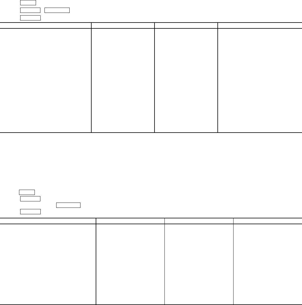
23
Table 2 — CVC/ICVC Display Data (cont)
EXAMPLE 2 — MAINTSTAT DISPLAY SCREEN
To access this display from the CVC/ICVC default screen:
1. Press .
2. Press ( will be highlighted).
3. Press .
NOTES:
1. Reset, Off, Local, CCN
2. Timeout, Ready, Recycle, Prestart, Start-up, Ramping, Running, Demand, Override, Shutdown, Trippout, Pumpdown, Lockout
3. Normal, Alert, Alarm
4. All variables with capital letter point names are available for CCN read operation. Those shown with (*) support write operations for all CCN
devices.
EXAMPLE 3 — STARTUP DISPLAY SCREEN
To access this display from the CVC/ICVC default screen:
1. Press .
2. Press .
3. Scroll down to highlight .
4. Press .
NOTE: All variables with CAPITAL LETTER point names are available for CCN read operation. Those shown with (**) shall support write
operations for the CVC/ICVC only.
DESCRIPTION STATUS UNITS POINT
Control Mode NOTE 1 NOTE 1 MODE
Run Status NOTE 2 NOTE 2 STATUS
Start Inhibit Timer 0-15 min T_START
Occupied? 0/1 NO/YES OCC
System Alert/Alarm 0-2 NOTE 3 SYS_ALM
*Chiller Start/Stop 0/1 STOP/START CHIL_S_S
*Remote Start Contact 0/1 OPEN/CLOSE REMCON
Temperature Reset –30-30 DEG F T_RESET
*Control Point 10-120 DEG F LCW_STPT
Chilled Water Temp –40-245 DEG F CHW_TMP
*Active Demand Limit 40-100 % DEM_LIM
Average Line Current 0-999 % %_AMPS
Motor Percent Kilowatts 0-999 % KW_P
Auto Demand Limit Input 4-20 mA AUTODEM
Auto Chilled Water Reset 4-20 mA AUTORES
Remote Reset Sensor –40-245 DEG F R_RESET
Total Compressor Starts 0-99999 c_starts
Starts in 12 Hours 0-8 STARTS
Compressor Ontime 0-500000.0 HOURS c_hrs
*Service Ontime 0-32767 HOURS S_HRS
Ice Build Contact 0-1 OPEN/CLOSE ICE_CON
Refrigerant Leak Sensor 0-20 mA REF_LEAK
DESCRIPTION STATUS UNITS POINT
Actual Guide Vane Pos 0-100 % GV_ACT
**Chilled Water Pump 0-1 OFF/ON CHWP
Chilled Water Flow 0-1 NO/YES CHW_FLOW
**Condenser Water Pump 0-1 OFF/ON CDP
Condenser Water Flow 0-1 NO/YES CDW_FLOW
Oil Pump Relay 0-1 OFF/ON OILR
**Oil Pump Delta P –6.7-200 ^PSI OILPD
Compressor Start Relay 0-1 OFF/ON CMPR
Compressor Start Contact 0-1 OPEN/CLOSED CR_AUX
Starter Trans Relay 0-1 OFF/ON CMPTRANS
Compressor Run Contact 0-1 OPEN/CLOSED RUN_AUX
**Tower Fan Relay Low 0-1 OFF/ON TFR_LOW
**Tower Fan Relay High 0-1 OFF/ON TFR_HIGH
Starter Fault 0-1 ALARM/NORMAL STR_FLT
Spare Safety Input 0-1 ALARM/NORMAL SAFETY
Shunt Trip Relay 0-1 OFF/ON TRIPR
ISM Fault Status 0-255 STRSTAT
MENU
STATUS MAINSTAT
SELECT
MENU
STATUS
STARTUP
SELECT
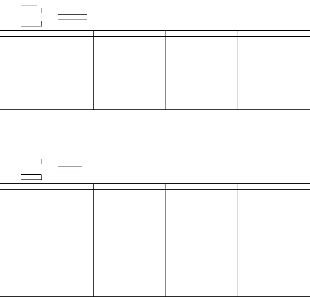
24
Table 2 — CVC/ICVC Display Data (cont)
EXAMPLE 4 — COMPRESS DISPLAY SCREEN
To access this display from the CVC/ICVC default screen:
1. Press .
2. Press .
3. Scroll down to highlight .
4. Press .
NOTE: All variables with CAPITAL LETTER point names are available for CCN read operation. Those shown with (**) shall support write operations
for the CVC/ICVC only.
EXAMPLE 5 — HEAT_EX DISPLAY SCREEN
To access this display from the CVC/ICVC default screen:
1. Press .
2. Press .
3. Scroll down to highlight .
4. Press .
NOTE: All variables with CAPITAL LETTER point names are available for CCN read operation. Those shown with (**) shall support write operations
for the CVC/ICVC only.
DESCRIPTION STATUS UNITS POINT
Actual Guide Vane Pos 0-100 % GV_ACT
Guide Vane Delta 0-100 % GV_DELTA
**Target Guide Vane Pos 0-100 % GV_TRG
Oil Sump Temp –40-245 DEG F OILT
**Oil Pump Delta P –6.7-200 ^PSI OILPD
Comp Discharge Temp –40-245 DEG F CMPD
Comp Thrust Brg Temp –40-245 DEG F MTRB
Comp Motor Winding Temp –40-245 DEG F MTRW
Spare Temperature 1 –40-245 DEG F SPARE1
Spare Temperature 2 –40-245 DEG F SPARE2
Oil Heater Relay 0/1 OFF/ON OILH
Diffuser Actuator 0-100 % DIFF_ACT
**Target VFD Speed 0-100 % VFD_OUT
**Actual VFD Speed 0-110 % VFD_ACT
Surge Protection Counts 0-5 SPC
DESCRIPTION STATUS UNITS POINT
**Chilled Water Delta P –6.7-420 PSI CHW_PD
Entering Chilled Water –40-245 DEG F ECW
Leaving Chilled Water –40-245 DEG F LCW
Chilled Water Delta T –6.7-420 ^F CHW_DT
Chill Water Pulldown/Min –20-20 ^F CHW_PULL
Evaporator Refrig Temp –40-245 DEG F ERT
**Evaporator Pressure –6.7-420 PSI ERP
Evaporator Approach 0-99 ^F EVAP_APP
**Condenser Water Delta P –6.7-420 PSI COND_PD
Entering Condenser Water –40-245 DEG F ECDW
Leaving Condenser Water –40-245 DEG F LCDW
Condenser Refrig Temp –40-245 DEG F CRT
**Condenser Pressure –6.7-420 PSI CRP
Condenser Approach 0-99 ^F COND_APP
Hot Gas Bypass Relay 0/1 OFF/ON HGBR
Surge / HGBP Active? 0/1 NO/YES SHG_ACT
Active Delta P 0-200 PSI dp_a
Active Delta T 0-200 DEG F dt_a
Surge / HGBP Delta T 0-200 DEG F dt_c
Head Pressure Reference 0-100 % hpr
Evaporator Saturation Temp
(ICVC only)
–40-245 ^F EST
MENU
STATUS
COMPRESS
SELECT
MENU
STATUS
HEAT_EX
SELECT
25
Table 2 — CVC/ICVC Display Data (cont)
EXAMPLE 6 — POWER DISPLAY SCREEN
To access this display from the CVC/ICVC default screen:
1. Press .
2. Press .
3. Scroll down to highlight .
4. Press .
NOTES:
1. All variables with CAPITAL LETTER point names are available for CCN read operation.
2. Those shown with (**) shall support write operations for CVC/ICVC only.
EXAMPLE 7 — ISM_STAT DISPLAY SCREEN
To access this display from the CVC/ICVC default screen:
1. Press .
2. Press .
3. Scroll down to highlight .
4. Press .
NOTE: All variables with CAPITAL LETTER point names are available for CCN read operation.
DESCRIPTION STATUS UNITS POINT
Average Line Current 0-999 % %_AMPS
Actual Line Current 0-99999 AMPS AMP_A
Average Line Voltage 0-999 % VOLT_P
Actual Line Voltage 0-99999 VOLTS VOLT_A
Power Factor 0.0-1.0 PF
Motor Kilowatts 0-99999 kW KW_A
**Motor Kilowatt-Hours 0-99999 kWH KWH
Demand Kilowatts 0-99999 kWH DEM_KWH
Line Current Phase 1 0-99999 AMPS AMPS_1
Line Current Phase 2 0-99999 AMPS AMPS_2
Line Current Phase 3 0-99999 AMPS AMPS_3
Line Voltage Phase 1 0-99999 VOLTS VOLTS_1
Line Voltage Phase 2 0-99999 VOLTS VOLTS_2
Line Voltage Phase 3 0-99999 VOLTS VOLTS_3
Ground Fault Phase 1 0-999 AMPS GF_1
Ground Fault Phase 2 0-999 AMPS GF_2
Ground Fault Phase 3 0-999 AMPS GF_3
Frequency 0-99 Hz FREQ
I2T Sum Heat-Phase 1 0-200 % HEAT1SUM
I2T Sum Heat-Phase 2 0-200 % HEAT2SUM
I2T Sum Heat-Phase 3 0-200 % HEAT3SUM
DESCRIPTION STATUS UNITS POINT
ISM Fault Status 0-223 ISMFLT
Single Cycle Dropout 0-1 NORMAL/ALARM CYCLE_1
Phase Loss 0-1 NORMAL/ALARM PH_LOSS
Overvoltage 0-1 NORMAL/ALARM OV_VOLT
Undervoltage 0-1 NORMAL/ALARM UN_VOLT
Current Imbalance 0-1 NORMAL/ALARM AMP_UNB
Voltage Imbalance 0-1 NORMAL/ALARM VOLT_UNB
Overload Trip 0-1 NORMAL/ALARM OVERLOAD
Locked Rotor Trip 0-1 NORMAL/ALARM LRATRIP
Starter LRA Trip 0-1 NORMAL/ALARM SLRATRIP
Ground Fault 0-1 NORMAL/ALARM GRND_FLT
Phase Reversal 0-1 NORMAL/ALARM PH_REV
Frequency Out of Range 0-1 NORMAL/ALARM FREQFLT
ISM Power on Reset 0-1 NORMAL/ALARM ISM_POR
Phase 1 Fault 0-1 NORMAL/ALARM PHASE_1
Phase 2 Fault 0-1 NORMAL/ALARM PHASE_2
Phase 3 Fault 0-1 NORMAL/ALARM PHASE_3
1CR Start Complete 0-1 FALSE/TRUE START_OK
1M Start/Run Fault 0-1 NORMAL/ALARM 1M_FLT
2M Start/Run Fault 0-1 NORMAL/ALARM 2M_FLT
Pressure Trip Contact 0-1 NORMAL/ALARM PRS_RIP
Starter Fault 0-1 NORMAL/ALARM STRT_FLT
Motor Amps Not Sensed 0-1 NORMAL/ALARM NO_AMPS
Starter Acceleration Fault 0-1 NORMAL/ALARM ACCELFLT
High Motor Amps 0-1 NORMAL/ALARM HIGHAMPS
1CR Stop Complete 0-1 FALSE/TRUE STOP_OK
1M/2M Stop Fault 0-1 NORMAL/ALARM 1M2MSTOP
Motor Amps When Stopped 0-1 NORMAL/ALARM AMPSTOP
Hardware Failure 0-1 NORMAL/ALARM HARDWARE
MENU
STATUS
POWER
SELECT
MENU
STATUS
ISM_STAT
SELECT
26
Table 2 — CVC/ICVC Display Data (cont)
EXAMPLE 8 — CVC/ICVC_PSWD DISPLAY SCREEN
To access this display from the CVC/ICVC default screen:
1. Press .
2. Press .
3. Scroll down to highlight .or
4. Press .
NOTE: All variables with CAPITAL LETTER point names are available for CCN read operation. Those shown with (**) shall support write operations
for the CVC/ICVC only.
EXAMPLE 9 — SETPOINT DISPLAY SCREEN
To access this display from the CVC/ICVC default screen:
1. Press .
2. Press .
3. Press .
NOTE: All variables are available for CCN read operation; forcing shall not be supported on setpoint screens.
EXAMPLE 10 — CAPACITY DISPLAY SCREEN
To access this display from the CVC/ICVC default screen:
1. Press .
2. Press .
3. Scroll down to highlight .
4. Press .
5. Scroll down to highlight .
6. Press .
NOTE: All variables with CAPITAL LETTER point names are available for CCN read operation; forcing shall not be supported on maintenance
screen.
DESCRIPTION STATUS UNITS POINT
Disable Service Password 0-1 DSABLE/ENABLE PSWD_DIS
**Remote Reset Option 0-1 DSABLE/ENABLE RESETOPT
Reset Alarm? 0-1 NO/YES REMRESET
CCN Mode? 0-1 NO/YES REM_CCN
DESCRIPTION STATUS UNITS POINT DEFAULT
Base Demand Limit 40-100 % DLM 100
Control Point
ECW Setpoint 15-120 DEG F ecw_sp 60.0
LCW Setpoint 10-120 DEG F lcw_sp 50.0
Ice Build Setpoint 15-60 DEG F ice_sp 40.0
Tower Fan High Setpoint 55-105 DEG F tf2_sp 75
DESCRIPTION STATUS UNITS POINT
Entering Chilled Water –40-245 DEG F ECW
Leaving Chilled Water –40-245 DEG F LCW
Capacity Control
Control Point 10-120 DEG F ctrlpt
Control Point Error –99-99 ^F cperr
ECW Delta T –99-99 ^F ecwdt
ECW Reset –99-99 ^F ecwres
LCW Reset –99-99 ^F lcwres
Total Error + Resets –99-99 ^F error
Guide Vane Delta –2-2 % gvd
Target Guide Vane Pos 0-100 % GV_TRG
Actual Guide Vane Pos 0-100 % GV_ACT
Target VFD Speed 0-100 % VFD_IN
Actual VFD Speed 0-100 % VFD_ACT
VFD Gain 0.1-1.5 vfd_gain
Demand Limit Inhibit 0-100 % DEM_INH
Amps/kW Ramp 0-100 % DMD_RAMP
VFD Load Factor 0-200 VFD_LF
MENU
STATUS
CVC ICVC
SELECT
MENU
SETPOINT
SELECT
MENU
SERVICE
CONTROL ALGORITHM STATUS
SELECT
CAPACITY
SELECT
27
Table 2 — CVC/ICVC Display Data (cont)
EXAMPLE 11 — OVERRIDE DISPLAY SCREEN
To access this display from the CVC/ICVC default screen:
1. Press .
2. Press .
3. Scroll down to highlight .
4. Press .
5. Scroll down to highlight .
6. Press .
NOTE: All variables with CAPITAL LETTER point names are available for CCN read operation; forcing shall not be supported on maintenance
screens.
EXAMPLE 12 — LL_MAINT DISPLAY SCREEN
To access this display from the CVC/ICVC default screen:
1. Press .
2. Press .
3. Scroll down to highlight .
4. Press .
5. Scroll down to highlight
6. Press .
NOTES:
1. DISABLE, LEAD, LAG, STANDBY, INVALID
2. DISABLE, LEAD, LAG, STANDBY, RECOVERY, CONFIG
3. Reset, Off, Local, CCN
4. Timeout, Ready, Recycle, Prestart, Startup, Ramping, Running, Demand, Override, Shutdown, Trippout, Pumpdown, Lockout
5. Stop, Start, Retain
6. All variables with CAPITAL LETTER point names are available for CCN read operation; forcing shall not be supported on maintenance screens.
DESCRIPTION STATUS UNITS POINT
Comp Motor Winding Temp –40-245 DEG F MTRW
Comp Motor Temp Override 150-200 DEG F mt_over
Condenser Pressure 0-420 PSI CRP
Cond Press Override 90-180 PSI cp_over
Evaporator Refrig Temp –40-245 DEG F ERT
Evap Ref Override Temp 2-45 DEG F rt_over
Comp Discharge Temp –40-245 DEG F CMPD
Comp Discharge Alert 125-200 DEG F cd_alert
Comp Thrust Brg Temp –40-245 DEG F MTRB
Comp Thrust Brg Alert 165-185 DEG F tb_alert
Actual Superheat –20-99 ^F SUPRHEAT
Superheat Required 6-99 ^F SUPR_REQ
Condenser Refrig Temp –40-245 DEG F CRT
DESCRIPTION STATUS UNITS POINT
LeadLag Control
LEADLAG: Configuration NOTE 1 leadlag
Current Mode NOTE 2 llmode
Load Balance Option 0/1 DSABLE/ENABLE loadbal
LAG START Time 2-60 MIN lagstart
LAG STOP Time 2-60 MIN lagstop
Prestart Fault Time 2-30 MIN preflt
Pulldown: Delta T / Min x.xx ^F pull_dt
Satisfied? 0/1 NO/YES pull_sat
LEAD CHILLER in Control 0/1 NO/YES leadctrl
LAG CHILLER: Mode NOTE 3 lagmode
Run Status NOTE 4 lagstat
Start/Stop NOTE 5 lag_s_s
Recovery Start Request 0/1 NO/YES lag_rec
STANDBY CHILLER: Mode NOTE 3 stdmode
Run Status NOTE 4 stdstat
Start/Stop NOTE 5 Std_s_s
Recovery Start Request 0/1 NO/YES std_rec
Spare Temperature 1 –40-245 DEG F SPARE_1
Spare Temperature 2 –40-245 DEG F SPARE_2
MENU
SERVICE
CONTROL ALGORITHM STATUS
SELECT
OVERRIDE
SELECT
MENU
SERVICE
CONTROL ALGORITHM STATUS
SELECT
LL_MAINT.
SELECT
28
Table 2 — CVC/ICVC Display Data (cont)
EXAMPLE 13 — ISM_HIST DISPLAY SCREEN
To access this display from the CVC/ICVC default screen:
1. Press .
2. Press .
3. Scroll down to highlight .
4. Press .
5. Scroll down to highlight .
6. Press .
NOTE: All variables with CAPITAL LETTER point names are available for CCN read operation; forcing shall not be supported on maintenance
screens.
EXAMPLE 14 — WSMDEFME DISPLAY SCREEN
To access this display from the CVC/ICVC default screen:
1. Press .
2. Press .
3. Scroll down to highlight .
4. Press .
5. Scroll down to highlight .
6. Press .
NOTE: All variables with CAPITAL LETTER point names are available for CCN read operation; forcing shall not be supported on maintenance
screens.
DESCRIPTION STATUS UNITS POINT
ISM FAULT HISTORY
Values At Last Fault:
Line Current Phase 1 0-99999 AMPS AMPS_1F
Line Current Phase 2 0-99999 AMPS AMPS_2F
Line Current Phase 3 0-99999 AMPS AMPS_3F
Line Voltage Phase 1 0-99999 VOLTS VOLTS_1F
Line Voltage Phase 2 0-99999 VOLTS VOLTS_2F
Line Voltage Phase 3 0-99999 VOLTS VOLTS_3F
Ground Fault Phase 1 0-999 AMPS GF_1F
Ground Fault Phase 2 0-999 AMPS GF_2F
Ground Fault Phase 3 0-999 AMPS GF_3F
I2T Sum Heat-Phase 1 0-200 % HEAT1SUMF
I2T Sum Heat-Phase 2 0-200 % HEAT2SUMF
I2T Sum Heat-Phase 3 0-200 % HEAT3SUMF
Phase 1 Faulted? 0/1 NO/YES PH1_FLT
Phase 2 Faulted? 0/1 NO/YES PH2_FLT
Phase 3 Faulted? 0/1 NO/YES PH3_FLT
Line Frequency 0-99 Hz FREQ_ F
ISM Fault Status 0-9999 ISM_STAT
DESCRIPTION STATUS UNITS POINT
WSM Active? 0/1 NO/YES WSMSTAT
Chilled Water Temp 0.0-99.9 DEG F CHWTEMP
Equipment Status 0/1 OFF/ON CHLRST
Commanded State XXXXXXXX TEXT CHLRENA
CHW setpt Reset Value 0.0-25.0 DEG F CHWRVAL
Current CHW Set Point 0.0-99.9 DEG F CHWSTPT
MENU
SERVICE
CONTROL ALGORITHM STATUS
SELECT
ISM_HIST
SELECT
MENU
SERVICE
CONTROL ALGORITHM STATUS
SELECT
WSMDEFME
SELECT
29
Table 2 — CVC/ICVC Display Data (cont)
EXAMPLE 15 — NET_OPT DISPLAY SCREEN
To access this display from the CVC/ICVC default screen:
1. Press .
2. Press .
3. Scroll down to highlight .
4. Press .
5. Scroll down to highlight .
6. Press .
NOTE: No variables are available for CCN read or write operation.
EXAMPLE 16 — ISM_CONF DISPLAY SCREEN
To access this display from the CVC/ICVC default screen:
1. Press .
2. Press .
3. Scroll down to highlight .
4. Press .
5. Enter password (4444 Factory Default).
6. Scroll down to highlight .
7. Press .
DESCRIPTION STATUS UNITS POINT DEFAULT
Loadshed Function
Group Number 0-99 ldsgrp 0
Demand Limit Decrease 0-60 % ldsdelta 20
Maximum Loadshed Time 0-120 MIN maxldstm 60
CCN Occupancy Config:
Schedule Number 3-99 occpcxxe 3
Broadcast Option 0-1 DSABLE/ENABLE occbrcst DSABLE
Alarm Configuration
Re-Alarm Time 0-1440 MIN 30
Alarm Routing 0-1 10000000
DESCRIPTION STATUS UNITS POINT DEFAULT
Starter Type 0-2 starter 1
(0 = Full, 1 = Red, 2 = SS/VFD)
Motor Rated Line Voltage 200-13200 VOLTS v_fs 460
Volt Transformer Ratio:1 1-35 vt_rat 1
Overvoltage Threshold 105-115 % overvolt 115
Undervoltage Threshold 85-95 % undvolt 85
Over/Under Volt Time 1-10 SEC uvuntime 5
Voltage % Imbalance 1-10 % v_unbal 10
Voltage Imbalance Time 1-10 SEC v_time 5
Motor Rated Load Amps 10-5000 AMPS a_fs 200
Motor Locked Rotor Trip 100-60000 AMPS motor_lr 1000
Locked Rotor Start Delay 1-10 cycles lrdelay 5
Starter LRA Rating 100-60000 AMPS start_lr 2000
Motor Current CT Ratio:1 3-1000 ct_turns 100
Current % Imbalance 5-40 % c_unbal 15
Current Imbalance Time 1-10 SEC c_time 5
Grnd Fault CT’s? 0-1 NO/YES gf_phase YES
Ground Fault CT Ratio:1 150 gf_ctr 150
Ground Fault Current 1-25 AMPS gf_amps 15
Ground Fault Start Delay 1-20 cycles gf_delay 10
Ground Fault Persistence 1-10 cycles gf_pers 5
Single Cycle Dropout 0/1 DSABLE/ENABLE cycdrop DSABLE
Frequency = 60 Hz? (No = 50) 0/1 NO/YES freq YES
Line Frequency Faulting 0/1 DSABLE/ENABLE freq_en DSABLE
MENU
SERVICE
EQUIPMENT CONFIGURATION
SELECT
NET_OPT
SELECT
MENU
SERVICE
ISM (STARTER) CONFIG DATA
SELECT
ISM_CONF
SELECT
30
Table 2 — CVC/ICVC Display Data (cont)
EXAMPLE 17 — OPTIONS DISPLAY SCREEN
To access this display from the CVC/ICVC default screen:
1. Press .
2. Press .
3. Scroll down to highlight .
4. Press .
5. Scroll down to highlight .
6. Press .
NOTE: No variables are available for CCN read or write operation.
EXAMPLE 18 — SETUP1 DISPLAY SCREEN
To access this display from the CVC/ICVC default screen:
1. Press .
2. Press .
3. Scroll down to highlight .
4. Press .
5. Scroll down to highlight .
6. Press .
NOTE: No variables are available for CCN read or write operation; forcing shall not be supported on service screens.
DESCRIPTION STATUS UNITS POINT DEFAULT
Auto Restart Option 0/1 DSABLE/ENABLE start DSABLE
Remote Contacts Option 0/1 DSABLE/ENABLE r_contact DSABLE
Soft Stop Amps Threshold 40-100 % softstop 100
Surge / Hot Gas Bypass
Surge Limit/HGBP Option 0/1 srg_hgbp 0
Select: Surge=0, HGBP=1
Min. Load Point (T1,P1)
Surge/HGBP Delta T1 0.5-20 ^F hgb_dt1 1.5
Surge/HGBP Delta P1 30-170 PSI hgb_dp1 50
Full Load Point (T2,P2)
Surge/HGBP Delta T2 0.5-20 ^F hbg_dt2 10
Surge/HGBP Delta P2 50-170 PSI hgb_dp2 85
Surge/HGBP Deadband 0.5-3 ^F hbg_db 1
Surge Protection
Surge Delta% Amps 5-20 % surge_a 10
Surge Time Period 7-10 MIN surge_t 8
Ice Build Control
Ice Build Option 0/1 DSABLE/ENABLE ibopt DSABLE
Ice Build Termination 0-2 ibterm 0
0=Temp, 1=Contacts, 2=Both
Ice Build Recycle 0/1 DSABLE/ENABLE ibrecyc DSABLE
Refrigerant Leak Option 0/1 DSABLE/ENABLE DSABLE
Refrigerant Leak Alarm mA 4-20 mA REF_LEAK 20
Head Pressure Reference
Delta P at 0% (4mA) 20-60 PSI HPDPO 25
Delta P at 100% (20mA) 20-60 PSI HPDP100 35
Minimum Output 0-100 % HPDPMIN% 0
DESCRIPTION STATUS UNITS POINT DEFAULT
Comp Motor Temp Override 150-200 DEG F mt_over 200
Cond Press Override 90-165 PSI cp_over 125
Comp Discharge Alert 125-200 DEG F cd_alert 200
Comp Thrust Brg Alert 165-185 DEG F tb_alert 175
Chilled Medium 0/1 WATER/BRINE medium WATER
Chilled Water Deadband .5-2.0 ^F cw _db 1.0
Evap Refrig Trippoint 0.0-40.0 DEG F ert_trip 33
Refrig Override Delta T 2.0-5.0 ^F ref_over 3
Condenser Freeze Point –20 - 35 DEG F cdfreeze 34
Evap Flow Delta P Cutout 0.5 - 50.0 PSI evap_cut 5.0
Cond Flow Delta P Cutout 0.5 - 50.0 PSI cond_cut 5.0
Water Flow Verify Time 0.5-5 MIN wflow_t 5
Oil Pressure Verify Time 15-300 SEC oilpr_t 40
Recycle Control
Restart Delta T 2.0-10.0 DEG F rcycr_dt 5
Shutdown Delta T 0.5-4.0 DEG F rcycs_dt 1
SPARE ALERT/ALARM ENABLE
Disable=0, Lo=1/3, Hi=2/4
Spare Temp #1 Enable 0-4 sp1_en 0
Spare Temp #1 Limit –40-245 DEG F sp1_lim 245
Spare Temp #2 Enable 0-4 sp2_ en 0
Spare Temp #2 Limit –40-245 DEG F sp2_ lim 245
MENU
SERVICE
EQUIPMENT SERVICE
SELECT
OPTIONS
SELECT
MENU
SERVICE
EQUIPMENT SERVICE
SELECT
SETUP1
SELECT
31
Table 2 — CVC/ICVC Display Data (cont)
EXAMPLE 19 — SETUP2 DISPLAY SCREEN
To access this display from the CVC/ICVC default screen:
1. Press .
2. Press .
3. Scroll down to highlight .
4. Press .
5. Scroll down to highlight .
6. Press .
NOTE: No variables are available for CCN read or write operation; forcing shall not be supported on service screens.
EXAMPLE 20 — LEADLAG DISPLAY SCREEN
To access this display from the CVC/ICVC default screen:
1. Press .
2. Press .
3. Scroll down to highlight .
4. Press .
5. Scroll down to highlight .
6. Press .
NOTE: No variables are available for CCN read or write operation.
DESCRIPTION STATUS UNITS POINT DEFAULT
Capacity Control
Proportional Inc Band 2-10 gv_inc 6.5
Proportional DEC Band 2-10 gv_dec 6.0
Proportional ECW Band 1-3 gw_ecw 2
Guide Vane Travel Limit 30-100 % gv_lim 80
Diffuser Control
Diffuser Option 0-1 DSABLE/ENABLE diff_opt DSABLE
Guide Vane 25% Load Pt 0-78 % gv_25 25
Diffuser 25% Load Point 0-100 % df_25 0
Guide Vane 50% Load Pt 0-78 % gv_50 50
Diffuser 50% Load Point 0-100 % df_50 0
Guide Vane 75% Load Pt 0-78 % gv_75 75
Diffuser 75% Load Point 0-100 % df_75 0
Diffuser Full Span mA 15-22 mA diff_ma 18
VFD Speed Control
VFD Option 0/1 DSABLE/ENABLE vfd_opt DSABLE
VFD Gain 0.1-1.5 vfd_gain 0.75
VFD Increase Step 1-5 % vfd_step 2
VFD Minimum Speed 65-100 % vfd_min 70
VFD Maximum Speed 90-100 % vfd_max 100
VFD Current Limit 0-99999 Amps vfdlim_i 250
DESCRIPTION STATUS UNITS POINT DEFAULT
Lead Lag Control
LEAD/LAG: Configuration 0-3 leadlag 0
DSABLE=0, Lead=1
LAG=2, STANDBY=3
Load Balance Option 0/1 DSABLE/ENABLE load/bal DSABLE
Common Sensor Option 0/1 DSABLE/ENABLE commsens DSABLE
LAG % Capacity 25-75 % lag_per 50
LAG Address 1-236 lag_add 92
LAG START Timer 2-60 MIN lagstart 10
LAG STOP Timer 2-60 MIN lagstop 10
PRESTART FAULT Timer 2-30 MIN preft 5
STANDBY Chiller Option 0/1 DSABLE/ENABLE stndopt DSABLE
STANDBY % Capacity 25-75 % stnd_per 50
STANDBY Address 1-236 stnd_add 93
MENU
SERVICE
EQUIPMENT SERVICE
SELECT
SETUP2
SELECT
MENU
SERVICE
EQUIPMENT SERVICE
SELECT
LEADLAG
SELECT
32
Table 2 — CVC/ICVC Display Data (cont)
EXAMPLE 21 — RAMP_DEM DISPLAY SCREEN
To access this display from the CVC/ICVC default screen:
1. Press .
2. Press .
3. Scroll down to highlight .
4. Press .
5. Scroll down to highlight .
6. Press .
NOTE: No variables are available for CCN read or write operation.
EXAMPLE 22 — TEMP_CTL DISPLAY SCREEN
To access this display from the CVC/ICVC default screen:
1. Press .
2. Press .
3. Scroll down to highlight .
4. Press .
5. Scroll down to highlight .
6. Press .
DESCRIPTION STATUS UNITS POINT DEFAULT
Pulldown Ramp Type: 0/1 ramp_opt 1
Select: Temp=0, Load=1
Demand Limit + kW Ramp
Demand Limit Source 0/1 dem_src 0
Select: Amps=0, kW=1
Motor Load Ramp% Min 5-20 kw_ramp 10
Demand Limit Prop Band 3-15 % dem_prop 10
Demand Limit At 20 mA 40-100 % dem_20ma 40
20 mA Demand Limit Opt 0/1 DSABLE/ENABLE dem_sel DSABLE
Motor Rated Kilowatts 50-9999 kW motor_kw 145
Demand Watts Interval 5-60 MIN dw_int 15
DESCRIPTION STATUS UNITS POINT DEFAULT
Control Point
ECW Control Option 0/1 DSABLE/ENABLE ecw_opt DSABLE
Temp Pulldown Deg/Min 2-10 ^F temp_ramp 3
Temperature Reset
RESET TYPE 1
Degrees Reset At 20 mA –30- 30 ^F deg_20ma 10
RESET TYPE 2
Remote Temp —> No Reset –40-245 DEG F res_rt1 85
Remote Temp —> Full Reset –40-245 DEG F res_rt2 65
Degrees Reset –30-30 ^F deg_rt 10
RESET TYPE 3
CHW Delta T —> No Reset 0-15 ^F restd_1 10
CHW Delta T —> Full Reset 0-15 ^F restd_2 0
Degrees Reset –30-30 ^F deg_chw 5
Select/Enable Reset Type 0-3 res_sel 0
MENU
SERVICE
EQUIPMENT SERVICE
SELECT
RAMP_DEM
SELECT
MENU
SERVICE
EQUIPMENT SERVICE
SELECT
TEMP_CTL
SELECT

33
PIC II System Functions
NOTE: Words not part of paragraph headings and printed in all
capital letters can be viewed on the CVC/ICVC (e.g., LOCAL,
CCN, RUNNING, ALARM, etc.). Words printed both in all
capital letters and italics can also be viewed on the CVC/ICVC
and are parameters (CONTROL MODE, TARGET GUIDE
VANE POS, etc.) with associated values (e.g., modes, tempera-
tures, pressures, percentages, on, off, enable, disable, etc.).
Words printed in all capital letters and in a box represent soft-
keys on the CVC/ICVC (e.g., and ). See
Table 2 for examples of the type of information that can appear
on the CVC/ICVC screens. Figures 14-20 give an overview of
CVC/ICVC operations and menus.
CAPACITY CONTROL FIXED SPEED — The PIC II con-
trols the chiller capacity by modulating the inlet guide vanes in
response to chilled water temperature deviation from the CON-
TROL POINT. The CONTROL POINT may be changed by a
CCN network device or is determined by the PIC II adding any
active chilled water reset to the SET POINT. The PIC II uses
the PROPORTIONAL INC (Increase) BAND, PROPOR-
TIONAL DEC (Decrease) BAND, and the PROPORTIONAL
ECW (Entering Chilled Water) GAIN to determine how fast or
slow to respond. CONTROL POINT may be viewed or over-
ridden from the MAINSTAT screen.
CAPACITY CONTROL VFD — The PIC II controls the
machine capacity by modulating the motor speed and inlet
guide vanes in response to chilled water temperature deviation
from the CONTROL POINT. The controller will maintain the
highest inlet guide vane setting at the lowest speed to maxi-
mize efficiency while avoiding surge. The CONTROL POINT
may be changed by a CCN network device or is determined by
the PIC II adding any active chilled water reset to the to the
SET POINT. CONTROL POINT may be viewed or overridden
from the MAINSTAT screen. The PIC II uses the PROPOR-
TIONAL INC (Increase) BAND, PROP DEC (Decrease)
BAND, and the PROPORTIONAL ECW (Entering Chilled
Water) GAIN to determine how fast or slow it takes the system
to respond. The VFD GAIN allows for additional adjustment of
the VFD response. At start-up, the inlet guide vanes (IGV)
start in the closed position and the VFD ramps to its minimum
speed setting.
The PIC II controller then initiates the Capacity Control al-
gorithm to maintain the chilled water temperature at the CON-
TROL POINT. During operation when the CONTROL POINT
is not met, the controller will establish a GUIDE VANE DELTA
which will either affect a percentage change to the GUIDE
VANES or the VFD TARGET SPEED. Any change that will be
made to the IGV position or the VFD SPEED will depend on
whether the GUIDE VANE DELTA is positive or negative, and
the status of the Surge Control Algorithm. The Surge Control
Algorithm determines if the chiller should operate in Normal
Mode or Surge Prevention Mode. The logic for how the IGV’s
and VFD SPEED will be affected by the GUIDE VANE DEL-
TA and the Surge Control Algorithm can be seen below:
Normal Control mode occurs when ACTIVE DELTA T >
SURGE/HGBP DELTA T.
Surge Prevention Mode occurs when ACTIVE DELTA T
≤ SURGE/HGBP DELTA T.
The TARGET VFD SPEED, ACTUAL VFD SPEED and the
VFD GAIN can be viewed and modified in the CAPACITY
display screen. The TARGET VFD SPEED can be manually
overridden by the operator from the COMPRESS screen. The
VFD MINIMUM SPEED, MAXIMUM SPEED, VFD GAIN
and INCREASE STEP can be viewed and modified in the
SETUP2 display screen. TARGET and ACTUAL VFD SPEED
can be viewed in the COMPRESS screen.
ECW CONTROL OPTION — If this option is enabled, the
PIC II uses the ENTERING CHILLED WATER temperature to
modulate the vanes instead of the LEAVING CHILLED
WATER temperature. The ECW CONTROL OPTION may be
viewed on the TEMP_CTL screen, which is accessed from the
EQUIPMENT SERVICE screen.
CONTROL POINT DEADBAND — This is the tolerance
range on the chilled water/brine temperature control point. If
the water temperature goes outside the CHILLED WATER
DEADBAND, the PIC II opens or closes the guide vanes until
the temperature is within tolerance. The PIC II may be config-
ured with a 0.5 to 2 F (0.3 to 1.1 C) deadband. CHILLED
WATER DEADBAND may be viewed or modified on the
SETUP1 screen, which is accessed from the EQUIPMENT
SERVICE table.
For example, a 1° F (0.6° C) deadband setting controls the
water temperature within ±0.5° F (0.3° C) of the control point.
This may cause frequent guide vane movement if the chilled
water load fluctuates frequently. A value of 1° F (0.6° C) is the
default setting.
DIFFUSER CONTROL — On 19XR FRAME sizes 4 and
5 compressors equipped with a variable discharge diffuser, the
PIC II adjusts the diffuser actuator position (DIFFUSER
ACTUATOR on the COMPRESS screen) to correspond to the
actual guide vane position (ACTUAL GUIDE VANE POS on
the COMPRESS screen).
The diffuser control can be enabled or disabled from the
SETUP2 screen. See Table 2, Example 19. In addition, the dif-
fuser and guide vane load points may be viewed and modified
from this screen. These points must be correct for the compres-
sor size. The diffuser opening can be incremented from fully
open to completely closed. A 0% setting is fully open; a 100%
setting is completely closed. To obtain the proper settings for
Diffuser Control, contact a Carrier Engineering representative.
PROPORTIONAL BANDS AND GAIN — Proportional band
is the rate at which the guide vane position is corrected in pro-
portion to how far the chilled water/brine temperature is from
the control point. Proportional gain determines how quickly the
guide vanes react to how quickly the temperature is moving
from the CONTROL POINT. The proportional bands and gain
may be viewed or modified from the SETUP2 screen, which is
accessed from the EQUIPMENT SERVICE table.
The Proportional Band — There are two response modes, one
for temperature response above the control point, the other for
the response below the control point.
The temperature response above the control point is called
the PROPORTIONAL INC BAND, and it can slow or quicken
guide vane response to chilled water/brine temperatures above
the DEADBAND. The PROPORTIONAL INC BAND can be
adjusted from a setting of 2 to 10; the default setting is 6.5.
The response below the control point is called the PRO-
PORTIONAL DEC BAND, and it can slow or quicken the
guide vane response to chilled water temperature below the
deadband plus the control point. The PROPORTIONAL DEC
BAND can be adjusted on the CVC/ICVC from a setting of 2 to
10. The default setting is 6.0.
NOTE: Increasing either of these settings causes the guide
vanes to respond more slowly than they would at a lower
setting.
GUIDE VANE
DELTA
NORMAL
CONTROL
MODE
SURGE
PREVENTION
MODE
IGV VFD IGV VFD
From +0.2 to +2.0 1st 2nd 2nd 1st
From –0.2 to –2.0 2nd 1st 1st —
ENTER EXIT

34
The PROPORTIONAL ECW GAIN can be adjusted on the
CVC/ICVC display for values of 1, 2, or 3; the default setting
is 2. Increase this setting to increase guide vane response to a
change in entering chilled water temperature.
DEMAND LIMITING — The PIC II responds to the ACTIVE
DEMAND LIMIT set point by limiting the opening of the
guide vanes. It compares the ACTIVE DEMAND LIMIT set
point to the DEMAND LIMIT SOURCE (either the AVERAGE
LINE CURRENT or the MOTOR KW). Depending on how the
control is configured. DEMAND LIMIT SOURCE is on the
RAMP_DEM screen. The default source is the compressor
motor current.
CHILLER TIMERS — The PIC II maintains 2 run time
clocks, known as COMPRESSOR ONTIME and SERVICE
ONTIME. COMPRESSOR ONTIME indicates the total life-
time compressor run hours. This timer can register up to
500,000 hours before the clock turns back to zero. The SER-
VICE ONTIME is a reset table timer that can be used to indi-
cate the hours since the last service visit or any other event.
The time can be changed from the CVC/ICVC to whatever
value is desired. This timer can register up to 32,767 hours
before it rolls over to zero.
The chiller also maintains a start-to-start timer and a stop-
to-start timer. These timers limit how soon the chiller can be
started. START INHIBIT TIMER is displayed on the MAIN-
STAT screen. See the Start-Up/Shutdown/Recycle Sequence
section, page 46, for more information on this topic.
OCCUPANCY SCHEDULE — The chiller schedule, de-
scribed in the Time Schedule Operation section (page 20), de-
termines when the chiller can run. Each schedule consists of
from 1 to 8 occupied or unoccupied time periods, set by the op-
erator. The chiller can be started and run during an occupied
time period (when OCCUPIED? is set to YES on the MAIN-
STAT display screen). It cannot be started or run during an un-
occupied time period (when OCCUPIED? is set to NO on the
MAINSTAT display screen). These time periods can be set for
each day of the week and for holidays. The day begins with
0000 hours and ends with 2400 hours. The default setting for
OCCUPIED? is YES, unless an unoccupied time period is in
effect.
These schedules can be set up to follow a building’s occu-
pancy schedule, or the chiller can be set so to run 100% of the
time, if the operator wishes. The schedules also can be by-
passed by forcing the CHILLER START/STOP parameter on
the MAINSTAT screen to START. For more information on
forced starts, see Local Start-Up, page 46.
The schedules also can be overridden to keep the chiller in
an occupied state for up to 4 hours, on a one time basis. See the
Time Schedule Operation section, page 20.
Figure 19 shows a schedule for a typical office building
with a 3-hour, off-peak, cool-down period from midnight to
3 a.m., following a weekend shutdown. Holiday periods are in
an unoccupied state 24 hours per day. The building operates
Monday through Friday, 7:00 a.m. to 6:00 p.m., and Saturdays
from 6:00 a.m. to 1:00 p.m. This schedule also includes the
Monday midnight to 3:00 a.m. weekend cool-down schedule.
NOTE: This schedule is for illustration only and is not
intended to be a recommended schedule for chiller operation.
Whenever the chiller is in the LOCAL mode, it uses Occu-
pancy Schedule 01 (OCCPC01S). When the chiller is in the
ICE BUILD mode, it uses Occupancy Schedule 02
(OCCPC02S). When the chiller is in CCN mode, it uses
Occupancy Schedule 03 (OCCPC03S).
The CCN SCHEDULE NUMBER is configured on the
NET_OPT display screen, accessed from the EQUIPMENT
CONFIGURATION table. See Table 2, Example 15. SCHED-
ULE NUMBER can be changed to any value from 03 to 99. If
this number is changed on the NET_OPT screen, the operator
must go to the ATTACH TO NETWORK DEVICE screen to
upload the new number into the SCHEDULE screen. See
Fig. 18.
Safety Controls — The PIC II monitors all safety control
inputs and, if required, shuts down the chiller or limits the
guide vanes to protect the chiller from possible damage from
any of the following conditions:
•high bearing temperature
•high motor winding temperature
•high discharge temperature
•low discharge superheat*
•low oil pressure
•low cooler refrigerant temperature/pressure
•condenser high pressure or low pressure
•inadequate water/brine cooler and condenser flow
•high, low, or loss of voltage
•ground fault
•voltage imbalance
•current imbalance
•excessive motor acceleration time
•excessive starter transition time
•lack of motor current signal
•excessive motor amps
•excessive compressor surge
•temperature and transducer faults
*Superheat is the difference between saturation temperature
and sensible temperature. The high discharge temperature
safety measures only sensible temperature.
Starter faults or optional protective devices within the starter
can shut down the chiller. The protective devices you have for
your application depend on what options were purchased.
If the PIC II control initiates a safety shutdown, it displays
the reason for the shutdown (the fault) on the CVC/ICVC dis-
play screen along with a primary and secondary message, ener-
gizes an alarm relay in the starter, and blinks the alarm light on
the control panel. The alarm is stored in memory and can be
viewed on the ALARM HISTORY and ISM_HIST screens on
the CVC/ICVC, along with a message for troubleshooting. If
the safety shutdown was also initiated by a fault detected in the
motor starter, the conditions at the time of the fault will be
stored in ISM_HIST.
To give more precise information or warnings on the
chiller’s operating condition, the operator can define alert lim-
its on various monitored inputs. Safety contact and alert limits
are defined in Table 3. Alarm and alert messages are listed in
the Troubleshooting Guide section, page 76.
If compressor motor overload occurs, check the motor for
grounded or open phases before attempting a restart.

35
Table 3 — Protective Safety Limits and Control Settings
Shunt Trip (Option) — The function of the shunt trip
option on the PIC II is to act as a safety trip. The shunt trip is
wired from an output on the ISM to a shunt trip equipped mo-
tor circuit breaker. If the PIC II tries to shut down the compres-
sor using a normal shutdown procedure but is unsuccessful for
20 seconds, the shunt trip output is energized and causes the
circuit breaker to trip off. If ground fault protection has been
applied to the starter, the ground fault trip also energizes the
shunt trip to trip the circuit breaker. Protective devices in the
starter can also energize the shunt trip. The shunt trip feature
can be tested using the Control Test feature.
Default Screen Freeze — When the chiller is in an
alarm state, the default CVC/ICVC display “freezes,” that is, it
stops updating. The first line of the CVC/ICVC default screen
displays a primary alarm message; the second line displays a
secondary alarm message.
The CVC/ICVC default screen freezes to enable the opera-
tor to see the conditions of the chiller at the time of the alarm. If
the value in alarm is one normally displayed on the default
screen, it flashes between normal and reverse video. The CVC/
ICVC default screen remains frozen until the condition that
caused the alarm is remedied by the operator. Use CVC/ICVC
display and alarm shutdown record sheet (CL-13) to record all
values from default screen freeze.
Knowledge of the operating state of the chiller at the time an
alarm occurs is useful when troubleshooting. Additional chiller
information can be viewed on the status screens and the
ISM_HIST screen. Troubleshooting information is recorded in
the ALARM HISTORY table, which can be accessed from the
SERVICE menu.
To determine what caused the alarm, the operator should
read both the primary and secondary default screen messages,
as well as the alarm history. The primary message indicates the
most recent alarm condition. The secondary message gives
more detail on the alarm condition. Since there may be more
than one alarm condition, another alarm message may appear
after the first condition is cleared. Check the ALARM HISTO-
RY screen for additional help in determining the reasons for the
alarms. Once all existing alarms are cleared (by pressing the
softkey), the default CVC/ICVC display returns to
normal operation.
MONITORED PARAMETER LIMIT APPLICABLE COMMENTS
TEMPERATURE SENSORS OUT OF
RANGE
–40 to 245 F (–40 to 118.3 C) Must be outside range for 2 seconds
PRESSURE TRANSDUCERS OUT OF
RANGE
0.06 to 0.98 Voltage Ratio Must be outside range for 3 seconds.
Ratio = Input Voltage ÷ Voltage Reference
COMPRESSOR DISCHARGE
TEMPERATURE
>220 F (104.4 C) Preset, alert setting configurable
MOTOR WINDING TEMPERATURE >220 F (104.4 C) Preset, alert setting configurable
BEARING TEMPERATURE >185 F (85 C) Preset, alert setting configurable
EVAPORATOR REFRIGERANT
TEMPERATURE
<33 F (for water chilling) (0.6°C) Preset, configurable chilled medium for water
(SETUP1 table)
<EVAP REFRIG TRIPPOINT (set point adjustable
from 0 to 40 F [–18 to 4 C]) for brine chilling)
Configure chilled medium for brine (SETUP1
table). Adjust EVAP REFRIG TRIPPOINT for
proper cutout
TRANSDUCER VOLTAGE <4.5 vdc> 5.5 vdc Preset
CONDENSER PRESSURE —SWITCH 165 ± 5 psig (1138 ± 34 kPa), reset at
110 ± 7 psig (758 ± 48 kPa)
Preset
—CONTROL 165 psig (1138 kPa) Preset
OIL PRESSURE Cutout <15 psid (103 kPad)
Alert <18 psid (124 kPad)
Preset
LIN E VOLTAG E —HIGH >150% for one second or >115% for ten seconds Preset, based on transformed line voltage
to ISM. Also monitored at CVC/ICVC and
CCM power input.
—LOW <85% for ten seconds or ≤80 for 5 seconds or
<75% for one second
—SINGLE-CYCLE <50% for one cycle (if enabled) Default is disabled.
COMPRESSOR MOTOR LOAD >110% for 30 seconds Preset
<15% with compressor running Preset
>15% with compressor off Preset
STARTER ACCELERATION TIME
(Determined by inrush current)
150% RLA for 20 sec. For chillers with reduced voltage mechanical
and solid-state starters
>100% RLA for 45 sec.
>100% RLA for 10 sec. For chillers with full voltage starters
(Configures on ISM_CONF table).
STARTER TRANSITION If ISM contact open >20 sec. Reduced voltage starters only
CONDENSER FREEZE PROTECTION Energizes condenser pump relay if
condenser refrigerant temperature or condenser
entering water temperature is below the configured
condenser freeze point temperature. Deenergizes
when the temperature is 5 F (3 C) above con-
denser freeze point temperature.
CONDENSER FREEZE POINT configured in
SETUP1 table with a default setting of 34 F
(1 C).
DISCHARGE SUPERHEAT Minimum value calculated based on
operating conditions and then compared
to actual superheat.
Calculated minimum required superheat
and actual superheat are shown on
OVERRIDE screen.
VARIABLE DIFFUSER OPERATION Detects discharge pulses caused by
incorrect diffuser position.
Preset, no calibration needed.
RESET

36
Ramp Loading — The ramp loading control slows down
the rate at which the compressor loads up. This control can pre-
vent the compressor from loading up during the short period of
time when the chiller is started and the chilled water loop has to
be brought down to CONTROL POINT. This helps reduce
electrical demand charges by slowly bringing the chilled water
to CONTROL POINT. The total power draw during this period
remains almost unchanged.
There are two methods of ramp loading with the PIC II.
Ramp loading can be based on chilled water temperature or on
motor load. Either method is selected from the RAMP__DEM
screen.
1. Temperature ramp loading (TEMP PULLDOWN DEG/
MIN) limits the degrees per minute rate at which either
leaving chilled water or entering chilled water tempera-
ture decreases. This rate is configured by the operator on
the TEMP_CTL screen. The lowest temperature ramp
rate will also be used if chiller power has been off for
3 hours or more (even if the motor ramp load is selected
as the ramp loading method).
2. Motor load ramp loading (LOAD PULLDOWN) limits
the degrees per minute rate at which the compressor mo-
tor current or compressor motor load increases. The
LOAD PULLDOWN rate is configured by the operator
on the RAMP_DEM screen in amps or kilowatts. The
point name is MOTOR LOAD RAMP%/MIN.
If kilowatts is selected for the DEMAND LIMIT SOURCE,
the MOTOR RATED KILOWATTS must be entered (informa-
tion found on the chiller Requisition form).
The TEMP PULLDOWN DEG/MIN may be viewed or
modified on the TEMP_CTL screen which is accessed from
the EQUIPMENT SERVICE screen. PULLDOWN RAMP
TYPE, DEMAND LIMIT SOURCE, and MOTOR LOAD
RAMP %/MIN may be viewed or modified on the
RAMP_DEM screen.
Capacity Override (Table 4) — Capacity overrides can
prevent some safety shutdowns caused by exceeding the motor
amperage limit, refrigerant low temperature safety limit, motor
high temperature safety limit, and condenser high pressure
limit. In all cases there are 2 stages of compressor vane control.
1. The vanes are prevented from opening further, and the
status line on the CVC/ICVC indicates the reason for the
override.
2. The vanes are closed until the condition decreases to be-
low the first step set point. Then the vanes are released to
normal capacity control.
Whenever the motor current demand limit set point
(ACTIVE DEMAND LIMIT) is reached, it activates a capacity
override, again, with a 2-step process. Exceeding 110% of the
rated load amps for more than 30 seconds will initiate a safety
shutdown.
The compressor high lift (surge prevention) set point will
cause a capacity override as well. When the surge prevention
set point is reached, the controller normally will only prevent
the guide vanes from opening. If so equipped, the hot gas by-
pass valve will open instead of holding the vanes. See the
Surge Prevention Algorithm section, page 39.
High Discharge Temperature Control — If the
discharge temperature increases above 160 F (71.1 C), the
guide vanes are proportionally opened to increase gas flow
through the compressor. If the leaving chilled water tempera-
ture is then brought 5° F (2.8° C) below the control set point
temperature, the PIC II will bring the chiller into the recycle
mode.
Oil Sump Temperature Control — The oil sump
temperature control is regulated by the PIC II, which uses the
oil heater relay when the chiller is shut down.
As part of the pre-start checks executed by the controls, the
oil sump temperature (OIL SUMP TEMP) is compared to the
cooler refrigerant temperature (EVAPORATOR REFRIG
TEMP). If the difference between these 2 temperatures is 50 F
(27.8 C) or less, the start-up will be delayed until the oil tem-
perature is 50 F (27.8 C) or more. Once this temperature is con-
firmed, the start-up continues.
The oil heater relay is energized whenever the chiller com-
pressor is off and the oil sump temperature is less than 140 F
(60.0 C) or the oil sump temperature is less than the cooler re-
frigerant temperature plus 53° F (11.7° C). The oil heater is
turned off when the oil sump temperature is either
•more than 152 F (66.7 C), or
•more than 142 F (61.1 C) and more than the cooler
refrigerant temperature plus 55° F (12.8° C).
The oil heater is always off during start-up or when the
compressor is running.
The oil pump is also energized during the time the oil is be-
ing heated (for 60 seconds at the end of every 30 minutes).
Oil Cooler — The oil must be cooled when the compres-
sor is running. This is accomplished through a small, plate-type
heat exchanger (also called the oil cooler) located behind the
oil pump. The heat exchanger uses liquid condenser refrigerant
as the cooling liquid. Refrigerant thermostatic expansion
valves (TXVs) regulate refrigerant flow to control the oil tem-
perature entering the bearings. The bulbs for the expansion
valves are strapped to the oil supply line leaving the heat ex-
changer, and the valves are set to maintain 110 F (43 C).
NOTE: The TXVs are not adjustable. The oil sump tempera-
ture may be at a lower temperature during compressor
operations.
Remote Start/Stop Controls — A remote device, such
as a timeclock that uses a set of contacts, may be used to start
and stop the chiller. However, the device should not be pro-
grammed to start and stop the chiller in excess of 2 or 3 times
every 12 hours. If more than 8 starts in 12 hours (the STARTS
IN 12 HOURS parameter on the MAINSTAT screen) occur, an
excessive starts alarm displays, preventing the chiller from
starting. The operator must press the softkey on the
CVC/ICVC to override the starts counter and start the chiller.
If the chiller records 12 starts (excluding recycle starts) in a
sliding 12-hour period, it can be restarted only by pressing the
softkey followed by the or softkey.
This ensures that, if the automatic system is malfunctioning,
the chiller will not repeatedly cycle on and off. If the automatic
restart after a power failure option (AUTO RESTART OPTION
on the OPTIONS screen) is not activated when a power failure
occurs, and if the remote contact is closed, the chiller will indi-
cate an alarm because of the loss of voltage.
The contacts for remote start are wired into the starter at ter-
minal strip J2, terminals 5 and 6 on the ISM. See the certified
drawings for further details on contact ratings. The contacts
must have 24 vac dry contact rating.
Spare Safety Inputs — Normally closed (NC) discrete
inputs for additional field-supplied safeties may be wired to the
spare protective limits input channel in place of the factory-
installed jumper. (Wire multiple inputs in series.) The opening
of any contact will result in a safety shutdown and a display on
the CVC/ICVC. Refer to the certified drawings for safety con-
tact ratings.
Analog temperature sensors may also be added to the mod-
ule (SPARE TEMP #1 and #2). The analog temperature sen-
sors may be configured to cause an alert or alarm on the CCN
network. The alert will not shut the chiller down. Configuring
for alarm state will cause the chiller to shut down.
RESET
RESET LOCAL CCN

37
Table 4 — Capacity Overrides
Alarm (Trip) Output Contacts — One set of alarm
contacts is provided in the starter. The contact ratings are pro-
vided in the certified drawings. The contacts are located on ter-
minal strip J9, terminals 15 and 16.
Refrigerant Leak Detector — An input is available
on the CCM module [terminal J5-5 (–) and J5-6 (+)] for a
refrigerant leak detector. Enabling REFRIGERANT LEAK
OPTION (OPTIONS screen) will allow the PIC II controls to
go into an alarm state at a user configured level (REFRIGER-
ANT LEAK ALARM mA). The input is configured for 4 to
20 mA by setting the DIP switch 1 on SW2 at the ON position,
or configured for 1 to 5 vdc by setting switch 1 at the OFF posi-
tion. The output of the refrigerant leak detector is displayed as
REFRIGERANT LEAK SENSOR on the MAINSTAT screen.
For a 1 to 5 vdc input, 1 vdc input represents 4 mA displayed
and 5 vdc input represents 20 mA displayed.
Kilowatt Output — An output is available on the CCM
module [Terminal J8-1 (+) and J8-2 (–)] to represent the power
consumption of the chiller. The 4 to 20 mA signal generated by
the CCM module can be wired to the building automation or
energy management system to monitor the chiller’s energy
consumption. A 4 mA signal represents the chiller in an off
state and a 20 mA signal represents the chiller operating at its
rated peak kilowatt consumption. The rated peak kilowatt con-
sumption is configured by the user in the RAMP_DEM display
screen by the setting the MOTOR RATED KILOWATTS from
the job data sheet.
Remote Reset of Alarms — A standard feature of the
PIC II controls is the ability to reset a chiller in a shutdown
alarm state from a remote location. If the condition which
caused the alarm has cleared the chiller can be placed back into
a normal CCN operating mode when the REMOTE RESET
OPTION (CVC_PSWD/ICVC_PSWD menu) is set to EN-
ABLE. A variety of Carrier Comfort Network software sys-
tems including ComfortVIEW™ or Network Service Tool™
can access the PIC II controls and reset the displayed alarm.
Third party software from building automation systems (BAS)
or energy management systems (EMS) can also access the
PIC II controls through a Carrier DataLINK™ module and re-
set the fault displayed. Both methods would access the
CVC_PSWD/ICVC_PSWD screen and force the RESET
ALARM? point to YES to reset the fault condition. If the PIC II
controls have determined that is safe to start the chiller the
CCN MODE? point (CVC_PSWD/ICVC_PSWD screen) can
be forced to YES to place the chiller back into normal CCN op-
erating mode. The only exceptions are the following alarms
that cannot be reset from a remote location: STATE #100, 205,
217-220, 223, 233, 234, 247, and 250. To view alarm codes, re-
fer to Troubleshooting Guide, Checking Display Messages,
page 76. After the alarm has been reset the PIC II control will
increment the Starts in 12 Hours counter by one upon restart. If
the limit of 8 starts in a 12-hour period occurs the alarm will be
required to be reset at the chiller control panel (CVC/ICVC).
Condenser Pump Control — The chiller will moni-
tor the condenser pressure (CONDENSER PRESSURE) and
may turn on the condenser pump if the condenser pressure be-
comes too high while the compressor is shut down. The con-
denser pressure override (COND PRESS OVERRIDE) parame-
ter is used to determine this pressure point. COND PRESS
OVERRIDE is found in the SETUP1 display screen, which is
accessed from the EQUIPMENT SERVICE table. The default
value is 125 psig (862 kPa).
If the CONDENSER PRESSURE is greater than or equal to
the COND PRESS OVERRIDE, and the entering condenser
water temperature (ENTERING CONDENSER WATER) is less
than 115 F (46 C), the condenser pump will energize to try to
decrease the pressure. The pump will turn off when the con-
denser pressure is 3.5 psi (24.1 kPa) less than the pressure over-
ride or when the condenser refrigerant temperature (CON-
DENSER REFRIG TEMP) is within 3° F (1.7° C) of the enter-
ing condenser water temperature (ENTERING CONDENSER
WATER).
OVERRIDE
CAPACITY CONTROL
FIRST STAGE SET POINT SECOND STAGE SET
POINT
OVERRIDE
TERMINATION
View/Modify
on CVC/ICVC
Screen
Default
Value
Configurable
Range Value Value
HIGH CONDENSER
PRESSURE SETUP1 125 psig
(862 kPa)
90 to 165 psig
(620 to 1138 kPa)
>Override
Set Point
+2.4 psid (16.5 kPad)
<Override
Set Point
HIGH MOTOR
TEMPERATURE SETUP1 >200 F
(93.3 C)
150 to 200 F
(66 to 93 C)
>Override
Set Point
+10° F (6° C)
<Override
Set Point
LOW REFRIGERANT
TEMPERATURE
(Refrigerant
Override Delta
Temperature)
SETUP1 3° F (1.6° C) 2° to 5° F
(1° to 3° C)
≤Trippoint
+ Override
∆T –1° F (0.56° C)
>Trippoint
+ Override
∆T+2° F (1.2° C)
HIGH COMPRESSOR
LIFT
(Surge Prevention)
OPTIONS
Min: T1 — 1.5° F
(0.8° C)
P1 — 50 psid
(345 kPad)
Max: T2 — 10° F
(5.6° C)
P2 — 85 psid
(586 kPad)
0.5° to 20° F
(0.3° to 8.3° C)
30 to 170 psid
(207 to 1172 kPad)
0.5° to 20° F
(0.3° to 8.3° C)
50 to 170 psid
(348 to 1172 kPad)
None
Within Lift Limits
Plus Surge/HGBP
Deadband Setting
MANUAL GUIDE VANE
TARGET CAPACITY Automatic 0 to 100% None Release of
Manual Control
MOTOR LOAD —
ACTIVE DEMAND LIMIT MAINSTAT 100% 40 to 100% ≥5% of
Set Point
2% Lower
Than Set Point
LOW DISCHARGE
SUPERHEAT OVERRIDE
Calculated Minimum
Superheat for
Conditions
None
2° F (1.1° C)
Below Calculated
Minimum Superheat
1° F (0.56° C)
Above Calculated
Minimum Superheat
38
Condenser Freeze Prevention — This control algo-
rithm helps prevent condenser tube freeze-up by energizing the
condenser pump relay. The PIC II controls the pump and, by
starting it, helps to prevent the water in the condenser from
freezing. The PIC II can perform this function whenever the
chiller is not running except when it is either actively in pump-
down or in pumpdown/lockout with the freeze prevention
disabled.
When the CONDENSER REFRIG TEMP is less than or
equal to the CONDENSER FREEZE POINT, the CONDENS-
ER WATER PUMP is energized until the CONDENSER RE-
FRIG TEMP is greater than the CONDENSER FREEZE
POINT plus 5° F (2.7° C) and the ENTERING CONDENSER
WATER TEMPERATURE is less than or equal to the CON-
DENSER FREEZE POINT. An alarm is generated if the chiller
is in PUMPDOWN mode and the pump is energized. An alert
is generated if the chiller is not in PUMPDOWN mode and the
pump is energized. If the chiller is in RECYCLE SHUT-
DOWN mode, the mode will transition to a non-recycle
shutdown.
Evaporator Freeze Protection (ICVC only) — A
refrigerant temperature sensor is installed at the bottom of the
cooler to provide redundant freeze protection. In place of the
cooler and condenser water pressure transducer inputs on the
CCM is a 4.3k ohm resister and a jumper lead. When the
EVAPORATOR REFRIGERANT TEMPERATURE is less
than the EVAP REFRIG TRIPPOINT plus the REFRIG
OVERRIDE DELTA T (configurable from 2° to 5°), state 122
will be displayed and a capacity override will occur. If the
EVAPORATOR REFRIG TEMP is equal to or less than the
EVAP Refrig TRIPPOINT, Protective Limit ALARM STATE
232 will be displayed and the unit will shut down.
Tower Fan Relay Low and High — Low condenser
water temperature can cause the chiller to shut down when re-
frigerant temperature is low. The tower fan relays, located in
the starter, are controlled by the PIC II to energize and deener-
gize as the pressure differential between cooler and condenser
vessels changes. This prevents low condenser water tempera-
ture and maximizes chiller efficiency. The tower fan relay can
only accomplish this if the relay has been added to the cooling
tower temperature controller.
The tower fan relay low is turned on whenever the condens-
er water pump is running, flow is verified, and the difference
between cooler and condenser pressure is more than 30 psid
(207 kPad) for entering condenser water temperature greater
than 65 F (18.3 C).
The tower fan relay low is turned off when the condenser
pump is off, flow is stopped, or the cooler refrigerant tempera-
ture is less than the override temperature for ENTERING CON-
DENSER WATER temperature less than 62 F (16.7 C), or the
differential pressure is less than 25 psid (172.4 kPad) for enter-
ing condenser water less than 80 F (27 C).
The tower fan relay high is turned on whenever the
condenser water pump is running, flow is verified and the dif-
ference between cooler and condenser pressure is more than
35 psid (241.3 kPa) for entering condenser water temperature
greater than the TOWER FAN HIGH SETPOINT (SETPOINT
menu, default 75 F [23.9 C]).
The tower fan relay high is turned off when the condenser
pump is off, flow is stopped, or the cooler refrigerant tempera-
ture is less than the override temperature and ENTERING
CONDENSER WATER is less than 70 F (21.1 C), or the differ-
ence between cooler and condenser pressure is less than
28 Psid (193 kPa), or ENTERING CONDENSER WATER
temperature is less than TOWER FAN HIGH SETPOINT
minus 3 F (–16.1 C).
The TOWER FAN RELAY LOW and HIGH parameters are
accessed from the STARTUP screen.
Auto. Restart After Power Failure — This option
may be enabled or disabled and may be viewed or modified on
the OPTIONS screen, which is accessed from the EQUIP-
MENT CONFIGURATION table. If the AUTO. RESTART
OPTION is enabled, the chiller will start up automatically after a
power failure has occurred (after a single cycle dropout; low,
high, or loss of voltage; and the power is within ± 15% of nor-
mal). The 15- and 5-minute inhibit timers are ignored during this
type of start-up.
When power is restored after the power failure and if the
compressor had been running, the oil pump will energize for
one minute before energizing the cooler pump. AUTO.
RESTART will then continue like a normal start-up.
If power to the CVC/ICVC module has been off for more
than 3 hours or the timeclock has been set for the first time,
start the compressor with the slowest temperature-based ramp
load rate possible in order to minimize oil foaming.
The oil pump is energized occasionally during the time the
oil is being brought up to proper temperature in order to elimi-
nate refrigerant that has migrated to the oil sump during the
power failure. The pump turns on for 60 seconds at the end of
every 30-minute period until the chiller is started.
Water/Brine Reset — Three types of chilled water or
brine reset are available and can be viewed or modified on the
TEMP_CTL screen, which is accessed from the EQUIPMENT
SERVICE table.
The CVC/ICVC default screen indicates when the chilled
water reset is active. TEMPERATURE RESET on the MAIN-
STAT screen indicates the amount of reset. The CONTROL
POINT will be determined by adding the TEMPERATURE
RESET to the SETPOINT.
To activate a reset type, access the TEMP_CTL screen and
input all configuration information for that reset type. Then, in-
put the reset type number (1, 2, or 3) in the SELECT/ENABLE
RESET TYPE input line.
RESET TYPE 1: 4 to 20 mA (1 to 5 vdc) TEMPERATURE
RESET — Reset Type 1 is an automatic chilled water temper-
ature reset based on a remote temperature sensor input config-
ured for either an externally powered 4 to 20 mA or a 1 to
5 vdc signal. Reset Type 1 permits up to ±30 F (±16 C) of
automatic reset to the chilled water set point.
The auto, chilled water reset is hardwired to terminals
J5-3 (–) and J5-4 (+) on the CCM. Switch setting number 2 on
SW2 will determine the type of input signal. With the switch
set at the ON position the input is configured for an externally
powered 4 to 20 mA signal. With the switch in the OFF posi-
tion the input is configured for an external 1 to 5 vdc signal.
RESET TYPE 2: REMOTE TEMPERATURE RESET —
Reset Type 2 is an automatic chilled water temperature reset
based on a remote temperature sensor input signal. Reset Type
2 permits ± 30° F (± 16° C) of automatic reset to the set point
based on a temperature sensor wired to the CCM module
IMPORTANT: A field-supplied water temperature control
system for condenser water should be installed. The system
should maintain the leaving condenser water temperature
at a temperature that is 20° F (11° C) above the leaving
chilled water temperature.
The tower fan relay control is not a substitute for a con-
denser water temperature control. When used with a water
temperature control system, the tower fan relay control can
be used to help prevent low condenser water temperatures.

39
(see wiring diagrams or certified drawings). The temperature
sensor must be wired to terminal J4-13 and J4-14. To configure
Reset Type 2, enter the temperature of the remote sensor at the
point where no temperature reset will occur (REMOTE TEMP
–> NO RESET). Next, enter the temperature at which the full
amount of reset will occur (REMOTE TEMP –> FULL
RESET). Then, enter the maximum amount of reset required to
operate the chiller (DEGREES RESET). Reset Type 2 can now
be activated.
RESET TYPE 3 — Reset Type 3 is an automatic chilled water
temperature reset based on cooler temperature difference.
Reset Type 3 adds ± 30° F (± 16° C) based on the temperature
difference between the entering and leaving chilled water
temperature.
To configure Reset Type 3, enter the chilled water tempera-
ture difference (the difference between entering and leaving
chilled water) at which no temperature reset occurs (CHW
DELTA T –> NO RESET). This chilled water temperature dif-
ference is usually the full design load temperature difference.
Next, enter the difference in chilled water temperature at which
the full amount of reset occurs (CHW DELTA T –> FULL RE-
SET). Finally, enter the amount of reset (DEGREES RESET).
Reset Type 3 can now be activated.
Demand Limit Control Option — The demand limit
control option (20 mA DEMAND LIMIT OPT) is externally
controlled by a 4 to 20 mA or 1 to 5 vdc signal from an energy
management system (EMS). The option is set up on the
RAMP_DEM screen. When enabled, 4 mA is the 100% de-
mand set point with an operator-configured minimum demand
at a 20 mA set point (DEMAND LIMIT AT 20 mA).
The auto. demand limit is hardwired to terminals J5-1 (–)
and J5-2 (+) on the CCM. Switch setting number 1 on SW2
will determine the type of input signal. With the switch set at
the ON position the input is configured for an externally pow-
ered 4 to 20 mA signal. With the switch in the OFF position the
input is configured for an external 1 to 5 vdc signal.
Surge Prevention Algorithm (Fixed Speed
Chiller) — This is an operator-configurable feature that can
determine if lift conditions are too high for the compressor and
then take corrective action. Lift is defined as the difference be-
tween the pressure at the impeller eye and at the impeller
discharge. The maximum lift a particular impeller wheel can
perform varies with the gas flow across the impeller and the
size of the wheel.
A surge condition occurs when the lift becomes so high the
gas flow across the impeller reverses. This condition can even-
tually cause chiller damage. The surge prevention algorithm
notifies the operator that chiller operating conditions are mar-
ginal and to take action to help prevent chiller damage such as
lowering entering condenser water temperature.
The surge prevention algorithm first determines if correc-
tive action is necessary. The algorithm checks 2 sets of opera-
tor-configured data points, the minimum load points (MIN.
LOAD POINT [T1,P1]) and the full load points (FULL LOAD
POINT [T2,P2]). These points have default settings as defined
on the OPTIONS screen or on Table 4.
The surge prevention algorithm function and settings are
graphically displayed in Fig. 21 and 22. The two sets of load
points on the graph (default settings are shown) describe a line
the algorithm uses to determine the maximum lift of the com-
pressor. When the actual differential pressure between the cool-
er and condenser and the temperature difference between the
entering and leaving chilled water are above the line on the
graph (as defined by the minimum and full load points), the al-
gorithm goes into a corrective action mode. If the actual values
are below the line and outside of the deadband region, the algo-
rithm takes no action. When the point defined by the ACTIVE
DELTA P and ACTIVE DELTA T, moves from the region
where the HOT GAS BYPASS/SURGE PREVENTION is off,
the point must pass through the deadband region to the line
determined by the configured values before the HOT GAS
BYPASS/SURGE PREVENTION will be turned on. As the
point moves from the region where the HOT GAS BYPASS/
SURGE PREVENTION is on, the point must pass through the
deadband region before the HOT GAS BYPASS/SURGE
PREVENTION is turned off. Information on modifying the de-
fault set points of the minimum and full load points may be
found in the Input Service Configurations section, page 55.
The state of the surge/hot gas bypass algorithm on the
HEAT_EX DISPLAY SCREEN (Surge/HGBP Active?).
Corrective action can be taken by making one of 2 choices.
If a hot gas bypass line is present and the hot gas option is
selected on the OPTIONS table (SURGE LIMIT/HGBP
OPTION is set to 1), the hot gas bypass valve can be energized.
If the hot gas bypass option is not selected (SURGE LIMIT/
HGBP OPTION is set to 0), hold the guide vanes. See Table 4,
LEGEND
∆P = (Condenser Psi) – (Cooler Psi)
∆T = (ECW) – (LCW)
Fig. 21 — 19XR Hot Gas Bypass/Surge
Prevention with Default English Settings
ECW —Entering Chilled Water
HGBP —Hot Gas Bypass
LCW —Leaving Chilled Water
LEGEND
∆P = (Condenser kPa) – (Cooler kPa)
∆T = (ECW) – (LCW)
Fig. 22 — 19XR Hot Gas Bypass/Surge
Prevention with Default Metric Settings
ECW —Entering Chilled Water
HGBP —Hot Gas Bypass
LCW —Leaving Chilled Water
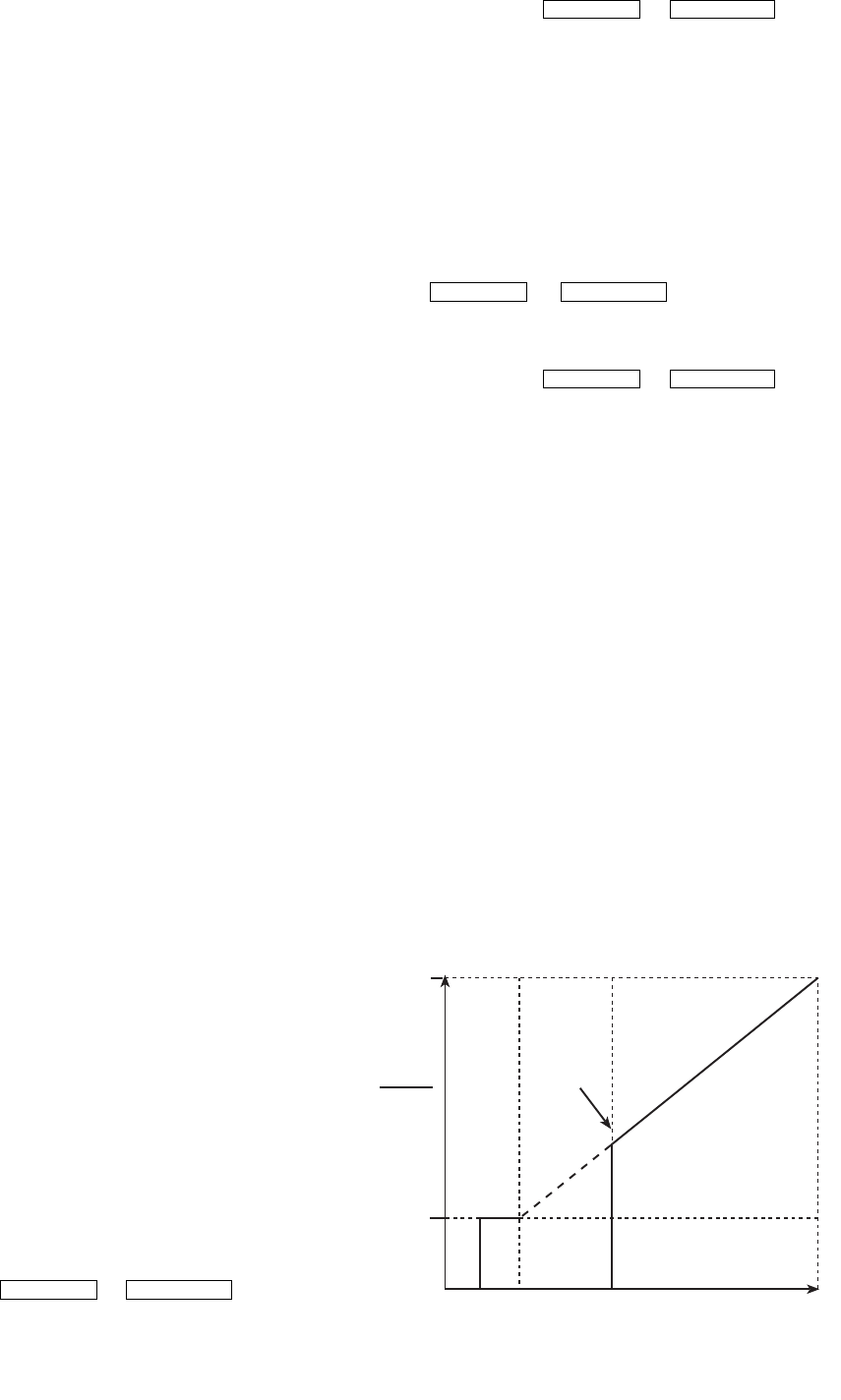
40
Capacity Overrides. Both of these corrective actions try to
reduce the lift experienced by the compressor and help prevent
a surge condition.
Surge Prevention Algorithm with VFD — This is
an operator configurable feature that can determine if lift con-
ditions are too high for the compressor and then take corrective
action. Lift is defined as the difference between the pressure at
the impeller eye and at the impeller discharge. The maximum
lift a particular impeller wheel can perform varies with the gas
flow through the impeller and the diameter of the impeller.
A surge condition occurs when the lift becomes so high the
gas flow across the impeller reverses. This condition can even-
tually cause chiller damage. When enabled, the Surge Preven-
tion Algorithm will adjust either the inlet guide vane (IGV)
position or compressor speed to maintain the compressor at a
safe distance from surge while maintaining machine efficiency.
If the surge condition degrades then the algorithm will move
aggressively away from surge. This condition can be identified
when the SURGE/HGBP ACTIVE? on the HEAT_EX display
screen displays a YES.
The surge prevention algorithm first determines if correc-
tive action is necessary. The algorithm checks two sets of
operator-configured data points, the lower surge point (MIN.
LOAD POINT [T1,P1]) and the upper surge point (FULL
LOAD POINT [T2,P2]). The surge characteristics vary be-
tween different chiller configurations and operating conditions.
The surge characteristics are factory set based on the original
selection with the values displayed inside the control panel of
the chiller. Since operating conditions may affect the surge pre-
vention algorithm, some field adjustments may be necessary.
The surge prevention algorithm function and settings are
graphically displayed on Fig. 21 and 22. The two sets of load
points on the graph (default settings are shown) describe a line
the algorithm uses to determine the maximum lift of the com-
pressor for the particular maximum operating speed. When the
actual differential pressure between the cooler and condenser
and the temperature difference between the entering and leav-
ing chilled water are above the line on the graph (as defined by
the minimum and full load points), the algorithm operates in
Surge Prevention mode. This is determined when the ACTIVE
DELTA T is less than SURGE/HGBP DELTA T minus the
deadband.
When in Surge Prevention mode, with a command to in-
crease capacity, the VFD speed will increase until maximum
VFD speed is reached. At VFD MAXIMUM SPEED, when Ca-
pacity still needs to increase, the IGV’s open. When in Surge
Prevention mode, with a command to decrease capacity only
the IGVs will close.
Surge Protection VFD Units — The PIC II monitors
surge, which is detected as a fluctuation in compressor motor
amperage. Each time the fluctuation exceeds an operator-
specified limit (SURGE DELTA % AMPS), the PIC II registers
a surge protection count. If more than 5 surges occur within an
operator-specified time (SURGE TIME PERIOD), the PIC II
initiates a surge protection shutdown of the chiller.
On VFD units, if a surge count is registered and if ACTUAL
VFD SPEED is less than VFD MAXIMUM SPEED then motor
speed will be increased by the configured VFD increase step.
While the SURGE PROTECTION COUNTS are >0, a speed
decrease will not be honored.
The surge limit can be adjusted from the OPTIONS screen
(see Table 2). Scroll down to the SURGE DELTA % AMPS
parameter, and use the or softkey
to adjust the percent of surge. The default setting is 10% amps.
The surge time period can also be adjusted from the
OPTIONS screen. Scroll to the SURGE TIME PERIOD
parameter, and use the or softkey
to adjust the amount of time. The default setting is 8 minutes.
Access the display screen (COMPRESS) to monitor the
surge count (SURGE PROTECTION COUNTS).
Surge Protection (Fixed Speed Chiller) —
The
PIC II monitors surge, which is a fluctuation in compressor
motor amperage. Each time the fluctuation exceeds an
operator-specified limit (SURGE DELTA % AMPS), the PIC II
counts the surge. If more than 5 surges occur within an
operator-specified time (SURGE TIME PERIOD), the PIC II
initiates a surge protection shutdown of the chiller.
The surge limit can be adjusted from the OPTIONS screen.
Scroll down to the SURGE DELTA % AMPS parameter, and
use the or softkey to adjust the
percent of surge. The default setting is 10% amps.
The surge time period can also be adjusted from the
OPTIONS screen. Scroll to the SURGE TIME PERIOD
parameter, and use the or softkey
to adjust the amount of time. The default setting is 8 minutes.
Access the display screen (COMPRESS) to monitor the
surge count (SURGE PROTECTION COUNTS).
HEAD PRESSURE REFERENCE OUTPUT (See
Fig. 23) — The PIC II control outputs a 4 to 20 mA signal for
the configurable Delta P (condenser pressure minus evaporator
pressure) reference curve shown in Fig. 23. An output is avail-
able on the ISM module [Terminal J8 (+), J8 (–) labeled spare].
For chillers with Benshaw Inc. solid-state starters terminal strip
labeled J8 (+), J8 (–) located next to the RediStart MICRO™
input/output card is provided. The Delta P at 100% (chiller at
maximum load condition default at 35 psi), DELTA P AT 0%
(chiller at minimum load condition default at 25 psi) and MIN-
IMUM OUTPUT points are configurable in the EQUIPMENT
SERVICE-OPTIONS table. When configuring this output en-
sure that minimum requirements for oil pressure and proper
condenser FLASC orifice performance are maintained. The 4
to 20 mA output can be used as a reference to control a
tower bypass valve, tower speed control, or condenser pump
speed control.
Lead/Lag Control — The lead/lag control system auto-
matically starts and stops a lag or second chiller in a 2-chiller
water system. A third chiller can be added to the lead/lag sys-
tem as a standby chiller to start up in case the lead or lag chiller
in the system has shut down during an alarm condition and ad-
ditional cooling is required. Refer to Fig. 17 and 18 for menu,
table, and screen selection information.
INCREASE DECREASE
INCREASE DECREASE
INCREASE DECREASE
INCREASE DECREASE
MINIMUM
REFERENCE
OUTPUT
DELTA P
AT 100%
DELTA P
AT 0%
DELTA P
0 mA 2 mA 4 mA
(0%) 20 mA
(100%)
4 T0 20 mA OUTPUT
Fig. 23 — Head Pressure Reference Output

41
NOTE: The lead/lag function can be configured on the LEAD-
LAG screen, which is accessed from the SERVICE menu and
EQUIPMENT SERVICE table. See Table 2, Example 20.
Lead/lag status during chiller operation can be viewed on the
LL_MAINT display screen, which is accessed from the SER-
VICE menu and CONTROL ALGORITHM STATUS table.
See Table 2, Example 12.
Lead/Lag System Requirements:
•all chillers in the system must have software capable of
performing the lead/lag function
•water pumps MUST be energized from the PIC II
controls
•water flows should be constant
•the CCN time schedules for all chillers must be identical
Operation Features:
•2 chiller lead/lag
•addition of a third chiller for backup
•manual rotation of lead chiller
•load balancing if configured
•staggered restart of the chillers after a power failure
•chillers may be piped in parallel or in series chilled water
flow
COMMON POINT SENSOR INSTALLATION — Lead/lag
operation does not require a common chilled water point sen-
sor. Common point sensors (Spare Temp #1 and #2) can be
added to the CCM module, if desired. Spare Temp #1 and #2
are wired to plug J4 terminals 25-26 and 27-28 (J4 lower,
respectively).
NOTE: If the common point sensor option is chosen on a
chilled water system, each chiller should have its own common
point sensor installed. Each chiller uses its own common point
sensor for control when that chiller is designated as the lead
chiller. The PIC II cannot read the value of common point sen-
sors installed on the other chillers in the chilled water system.
If leaving chilled water control (ECW CONTROL OPTION
is set to 0 [DSABLE] TEMP_CTL screen) and a common
point sensor is desired (COMMON SENSOR OPTION in
LEADLAG screen selected as 1) then the sensor is wired in
Spare Temp #1 position on the CCM.
If the entering chilled water control option (ECW CON-
TROL OPTION) is enabled (configured in TEMP_CTL
screen) and a common point sensor is desired (COMMON
SENSOR OPTION in LEADLAG screen selected as 1) then
the sensor is wired in Spare Temp #2 position on the CCM.
When installing chillers in series, a common point sensor
should be used. If a common point sensor is not used, the leav-
ing chilled water sensor of the upstream chiller must be moved
into the leaving chilled water pipe of the downstream chiller.
If return chilled water control is required on chillers piped in
series, the common point return chilled water sensor should be
installed. If this sensor is not installed, the return chilled water
sensor of the downstream chiller must be relocated to the return
chilled water pipe of the upstream chiller.
To properly control the common supply point temperature
sensor when chillers are piped in parallel, the water flow
through the shutdown chillers must be isolated so no water by-
pass around the operating chiller occurs. The common point
sensor option must not be used if water bypass around the oper-
ating chiller is occurring.
CHILLER COMMUNICATION WIRING — Refer to the
chiller’s Installation Instructions, Carrier Comfort Network
Interface section for information on chiller communication
wiring.
LEAD/LAG OPERATION — The PIC II not only has the
ability to operate 2 chillers in lead/lag, but it can also start a
designated standby chiller when either the lead or lag chiller is
faulted and capacity requirements are not met. The lead/lag op-
tion only operates when the chillers are in CCN mode. If any
other chiller configured for lead/lag is set to the LOCAL or
OFF modes, it will be unavailable for lead/lag operation.
Lead/Lag Chiller Configuration and Operation
•A chiller is designated the lead chiller when its
LEADLAG: CONFIGURATION value on the LEAD-
LAG screen is set to “1.”
•A chiller is designated the lag chiller when its
LEADLAG: CONFIGURATION value is set to “2.”
•A chiller is designated as a standby chiller when its
LEADLAG: CONFIGURATION value is set to “3.”
•A value of “0” disables the lead/lag designation of a
chiller.
To configure the LAG ADDRESS value on the LEADLAG
screen, always enter the address of the other chiller on the sys-
tem. For example, if you are configuring chiller A, enter the ad-
dress for chiller B as the lag address. If you are configuring
chiller B, enter the address for chiller A as the lag address. This
makes it easier to rotate the lead and lag chillers.
If the address assignments in the LAG ADDRESS and
STANDBY ADDRESS parameters conflict, the lead/lag func-
tion is disabled and an alert (!) message displays. For example,
if the LAG ADDRESS matches the lead chiller’s address, the
lead/lag will be disabled and an alert (!) message displayed.
The lead/lag maintenance screen (LL_MAINT) displays the
message ‘INVALID CONFIG’ in the LEADLAG: CONFIGU-
RATION and CURRENT MODE fields.
The lead chiller responds to normal start/stop controls such
as the occupancy schedule, a forced start or stop, and remote
start contact inputs. After completing start-up and ramp load-
ing, the PIC II evaluates the need for additional capacity. If ad-
ditional capacity is needed, the PIC II initiates the start-up of
the chiller configured at the LAG ADDRESS. If the lag chiller
is faulted (in alarm) or is in the OFF or LOCAL modes, the
chiller at the STANDBY ADDRESS (if configured) is requested
to start. After the second chiller is started and is running, the
lead chiller monitors conditions and evaluates whether the ca-
pacity has been reduced enough for the lead chiller to sustain
the system alone. If the capacity is reduced enough for the lead
chiller to sustain the CONTROL POINT temperatures alone,
then the operating lag chiller is stopped.
If the lead chiller is stopped in CCN mode for any reason
other than an alarm (*) condition, the lag and standby chillers
are also stopped. If the configured lead chiller stops for an
alarm condition, the configured lag chiller takes the lead chill-
er’s place as the lead chiller, and the standby chiller serves as
the lag chiller.
If the configured lead chiller does not complete the start-up
before the PRESTART FAULT TIMER (a user-configured
value) elapses, then the lag chiller starts and the lead chiller
shuts down. The lead chiller then monitors the start request
from the acting lead chiller. The PRESTART FAULT TIMER is
initiated at the time of a start request. The PRESTART FAULT
TIMER provides a timeout if there is a prestart alert condition
that prevents the chiller from starting in a timely manner. The
PRESTART FAULT TIMER parameter is on the LEADLAG
screen, which is accessed from the EQUIPMENT SERVICE
table of the SERVICE menu.
If the lag chiller does not achieve start-up before the PRE-
START FAULT TIMER elapses, the lag chiller stops, and the
standby chiller is requested to start, if configured and ready.

42
Standby Chiller Configuration and Operation — A chiller is
designated as a standby chiller when its LEADLAG: CONFIG-
URATION value on the LEADLAG screen is set to “3.” The
standby chiller can operate as a replacement for the lag chiller
only if one of the other two chillers is in an alarm (*) condition
(as shown on the CVC/ICVC panel). If both lead and lag chill-
ers are in an alarm (*) condition, the standby chiller defaults to
operate in CCN mode, based on its configured occupancy
schedule and remote contacts input.
Lag Chiller Start-Up Requirements — Before the lag chiller
can be started, the following conditions must be met:
1. Lead chiller ramp loading must be complete.
2. Lead chilled water temperature must be greater than the
CONTROL POINT temperature (see the MAINSTAT
screen) plus 1/2 the CHILLED WATER DEADBAND
temperature (see the SETUP1 screen).
NOTE: The chilled water temperature sensor may be the
leaving chilled water sensor, the return water sensor, the
common supply water sensor, or the common return wa-
ter sensor, depending on which options are configured
and enabled.
3. Lead chiller ACTIVE DEMAND LIMIT (see the MAIN-
STAT screen) value must be greater than 95% of full load
amps.
4. Lead chiller temperature pulldown rate (TEMP PULL-
DOWN DEG/MIN on the TEMP_CTL screen) of the
chilled water temperature is less than 0.5° F (0.27° C) per
minute.
5. The lag chiller status indicates it is in CCN mode and is
not in an alarm condition. If the current lag chiller is in an
alarm condition, the standby chiller becomes the active
lag chiller, if it is configured and available.
6. The configured LAG START TIMER entry has elapsed.
The LAG START TIMER starts when the lead chiller ramp
loading is completed. The LAG START TIMER entry is
on the LEADLAG screen, which is accessed from the
EQUIPMENT SERVICE table of the SERVICE menu.
When all the above requirements have been met, the lag
chiller is commanded to a STARTUP mode (SUPVSR flashing
next to the point value on the STATUS table). The PIC II con-
trol then monitors the lag chiller for a successful start. If the lag
chiller fails to start, the standby chiller, if configured, is started.
Lag Chiller Shutdown Requirements — The following condi-
tions must be met in order for the lag chiller to be stopped.
1. Lead chiller compressor motor average line current or
load value (MOTOR PERCENT KILOWATTS on the
MAINSTAT screen) is less than the lead chiller percent
capacity.
NOTE: Lead chiller percent capacity = 115 – LAG % CA-
PACI T Y. The LAG % CAPACITY parameter is on the
LEADLAG screen, which is accessed from the EQUIP-
MENT SERVICE table on the SERVICE menu.
2. The lead chiller chilled water temperature is less than the
CONTROL POINT temperature (see the MAINSTAT
screen) plus 1/2 the CHILLED WATER DEADBAND tem-
perature (see the SETUP1 screen).
3. The configured LAG STOP TIMER entry has elapsed.
The LAG STOP TIMER starts when the lead chiller
chilled water temperature is less than the chilled water
CONTROL POINT plus 1/2 of the CHILLED WATER
DEADBAND and the lead chiller compressor motor load
(MOTOR PERCENT KILOWATT or AVERAGE LINE
CURRENT on the MAINSTAT screen) is less than the
lead chiller percent capacity.
NOTE: Lead chiller percent capacity = 115 – LAG % CAPAC-
ITY. The LAG % CAPACITY parameter is on the LEADLAG
screen, which is accessed from the EQUIPMENT SERVICE
table on the SERVICE menu.
FAULTED CHILLER OPERATION — If the lead chiller
shuts down because of an alarm (*) condition, it stops commu-
nicating to the lag and standby chillers. After 30 seconds, the
lag chiller becomes the acting lead chiller and starts and stops
the standby chiller, if necessary.
If the lag chiller goes into alarm when the lead chiller is also
in alarm, the standby chiller reverts to a stand-alone CCN
mode of operation.
If the lead chiller is in an alarm (*) condition (as shown on
the CVC/ICVC panel), press the softkey to clear the
alarm. The chiller is placed in CCN mode. The lead chiller
communicates and monitors the RUN STATUS of the lag and
standby chillers. If both the lag and standby chillers are run-
ning, the lead chiller does not attempt to start and does not as-
sume the role of lead chiller until either the lag or standby chill-
er shuts down. If only one chiller is running, the lead chiller
waits for a start request from the operating chiller. When the
configured lead chiller starts, it assumes its role as lead chiller.
If the lag chiller is the only chiller running when the lead
chiller assumes its role as a lead chiller then the lag chiller will
perform a RECOVERY START REQUEST (LL_MAINT
screen). The lead chiller will start up when the following condi-
tions are met.
1. Lag chiller ramp loading must be complete.
2. Lag CHILLED WATER TEMP (MAINSTAT screen) is
greater than CONTROL POINT plus 1/2 the CHILLED
WATER DEADBAND temperature.
3. Lag chiller ACTIVE DEMAND LIMIT value must be
greater than 95% of full load amps.
4. Lag chiller temperature pulldown rate (TEMP PULL-
DOWN DEG/MIN) of the chilled water temperature is
less than 0.5 F (0.27 C) per minute.
5. The standby chiller is not running as a lag chiller.
6. The configured LAG START TIMER has elapsed. The
LAG START TIMER is started when ramp loading is
completed.
LOAD BALANCING — When the LOAD BALANCE
OPTION (see LEADLAG screen) is enabled, the lead chiller
sets the ACTIVE DEMAND LIMIT in the lag chiller to the lead
chiller’s compressor motor load value MOTOR PERCENT
KILOWATTS or AVERAGE LINE CURRENT on the MAIN-
STAT screen). This value has limits of 40% to 100%. When the
lag chiller ACTIVE DEMAND LIMIT is set, the CONTROL
POINT must be modified to a value of 3° F (1.67° C) less than
the lead chiller’s CONTROL POINT value. If the LOAD BAL-
ANCE OPTION is disabled, the ACTIVE DEMAND LIMIT
and the CONTROL POINT are forced to the same value as the
lead chiller.
AUTO. RESTART AFTER POWER FAILURE — When an
auto. restart condition occurs, each chiller may have a delay
added to the start-up sequence, depending on its lead/lag con-
figuration. The lead chiller does not have a delay. The lag chill-
er has a 45-second delay. The standby chiller has a 90-second
delay. The delay time is added after the chiller water flow is
verified. The PIC II ensures the guide vanes are closed. After
the guide vane position is confirmed, the delay for lag and
standby chillers occurs prior to energizing the oil pump. The
normal start-up sequence then continues. The auto. restart de-
lay sequence occurs whether the chiller is in CCN or LOCAL
mode and is intended to stagger the compressor motor starts.
Preventing the motors from starting simultaneously helps re-
duce the inrush demands on the building power system.
RESET
43
Ice Build Control — The ice build control option auto-
matically sets the CONTROL POINT of the chiller to a temper-
ature that allows ice building for thermal storage.
NOTE: For ice build control to operate properly, the PIC II
must be in CCN mode.
NOTE: See Fig. 17 and 18 for more information on ice build-
related menus.
The PIC II can be configured for ice build operation.
•From the SERVICE menu, access the EQUIPMENT
SERVICE table. From there, select the OPTIONS screen
to enable or disable the ICE BUILD OPTION. See
Table 2, Example 17.
•The ICE BUILD SETPOINT can be configured from the
SETPOINT display, which is accessed from the PIC II
main menu. See Table 2, Example 9.
•The ice build schedule can be viewed or modified from
the SCHEDULE table. From this table, select the ice
build schedule (OCCPC02S) screen. See Fig. 19 and the
section on Time Schedule Operation, page 20, for more
information on modifying chiller schedules.
The ice build time schedule defines the period(s) during
which ice build is active if the ice build option is enabled. If the
ice build time schedule overlaps other schedules, the ice build
time schedule takes priority. During the ice build period, the
CONTROL POINT is set to the ICE BUILD SETPOINT for
temperature control. The ICE BUILD RECYCLE and ICE
BUILD TERMINATION parameters, accessed from the
OPTIONS screen, allow the chiller operator to recycle or ter-
minate the ice build cycle. The ice build cycle can be config-
ured to terminate if:
•the ENTERING CHILLED WATER temperature is less
than the ICE BUILD SETPOINT. In this case, the opera-
tor sets the ICE BUILD TERMINATION parameter to 0
on the OPTIONS screen.
•the REMOTE CONTACT inputs from an ice level indi-
cator are opened. In this case, the operator sets the ICE
BUILD TERMINATION parameter to 1 on the OPTIONS
screen.
•the chilled water temperature is less than the ice build set
point and the remote contact inputs from an ice level
indicator are open. In this case, the operator sets the ICE
BUILD TERMINATION parameter to 2 on the OPTIONS
screen.
•the end of the ice build time schedule has been reached.
ICE BUILD INITIATION — The ice build time schedule
(OCCPC02S) is the means for activating the ice build option.
The ice build option is enabled if:
•a day of the week and a time period on the ice build time
schedule are enabled. The SCHEDULE screen shows an
X in the day field and ON/OFF times are designated for
the day(s),
•and the ICE BUILD OPTION is enabled.
The following events take place (unless overridden by a
higher authority CCN device).
•CHILLER START/STOP is forced to START.
•The CONTROL POINT is forced to the ICE BUILD SET-
POINT.
•Any force (Auto) is removed from the ACTIVE
DEMAND LIMIT.
NOTE: A parameter’s value can be forced, that is, the value
can be manually changed at the CVC/ICVC by an operator,
changed from another CCN device, or changed by other algo-
rithms in the PIC II control system.
NOTE: The Ice Build steps do not occur if the chiller is config-
ured and operating as a lag or standby chiller for lead/lag oper-
ation and is actively being controlled by a lead chiller. The lead
chiller communicates the ICE BUILD SET POINT, the desired
CHILLER START/STOP state, and the ACTIVE DEMAND
LIMIT to the lag or standby chiller as required for ice build, if
configured to do so.
START-UP/RECYCLE OPERATION — If the chiller is not
running when ice build activates, the PIC II checks the follow-
ing conditions, based on the ICE BUILD TERMINATION
value, to avoid starting the compressor unnecessarily:
•if ICE BUILD TERMINATION is set to the TEMP option
and the ENTERING CHILLED WATER temperature is
less than or equal to the ICE BUILD SETPOINT;
•if ICE BUILD TERMINATION is set to the CONTACTS
option and the remote contacts are open;
•if the ICE BUILD TERMINATION is set to the BOTH
(temperature and contacts) option and the ENTERING
CHILLED WATER temperature is less than or equal to
the ICE BUILD SETPOINT and the remote contacts are
open.
The ICE BUILD RECYCLE on the OPTIONS screen deter-
mines whether or not the chiller will go into an ice build RE-
CYCLE mode.
•If the ICE BUILD RECYCLE is set to DSABLE (dis-
able), the PIC II reverts to normal temperature control
when the ice build function terminates.
•If the ICE BUILD RECYCLE is set to ENABLE, the PIC
II goes into an ICE BUILD RECYCLE mode and the
chilled water pump relay remains energized to keep the
chilled water flowing when the ice build function termi-
nates. If the temperature of the ENTERING CHILLED
WATER increases above the ICE BUILD SETPOINT plus
the RECYCLE RESTART DELTA T value, the compres-
sor restarts and controls the chilled water/brine tempera-
ture to the ICE BUILD SETPOINT.
TEMPERATURE CONTROL DURING ICE BUILD —
During ice build, the capacity control algorithm shall use the
CONTROL POINT minus 5 F (–2.8 C) for control of the
LEAVING CHILLED WATER temperature. (See Table 2, ex-
ample 10, the CAPACITY CONTROL parameter on the CA-
PACITY screen.) The ECW CONTROL OPTION and any tem-
perature reset option shall be ignored, if enabled, during ice
build. The AUTO DEMAND LIMIT INPUT shall also be
ignored if enabled during ice build.
•ECW CONTROL OPTION and any temperature reset
options (configured on TEMP_CTL screen).
•20 mA DEMAND LIMIT OPT (configured on
RAMP_DEM screen).
TERMINATION OF ICE BUILD — The ice build function
terminates under the following conditions:
1. Time Schedule — When the current time on the ice build
time schedule (OCCPC02S) is not set as an ice build time
period.
2. Entering Chilled Water Temperature — Compressor
operation terminates, based on temperature, if the ICE
BUILD TERMINATION parameter is set to 0 (TEMP),
the ENTERING CHILLED WATER temperature is less
than the ICE BUILD SETPOINT, and the ICE BUILD
RECYCLE is set to DSABLE. If the ICE BUILD RECY-
CLE OPTION is set to ENABLE, a recycle shutdown oc-
curs and recycle start-up depends on the LEAVING
CHILLED WATER temperature being greater than the
water/brine CONTROL POINT plus the RESTART
DELTA T temperature.
3. Remote Contacts/Ice Level Input — Compressor opera-
tion terminates when the ICE BUILD TERMINATION
parameter is set to 1 (CONTACTS) and the remote con-
tacts are open and the ICE BUILD RECYCLE is set to
DSABLE (0). In this case, the contacts provide ice level
termination control. The contacts are used to stop the ice
build function when a time period on the ice build sched-
ule (OCCPC02S) is set for ice build operation. The re-
mote contacts can still be opened and closed to start and
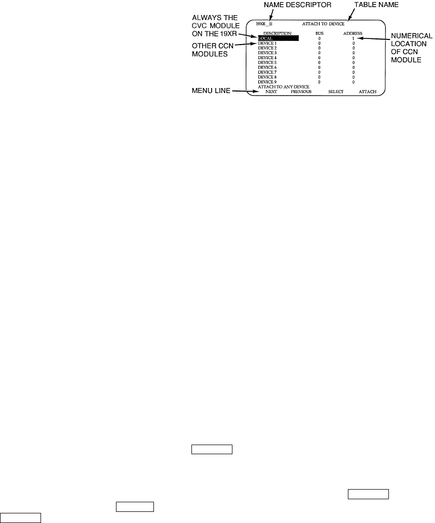
44
stop the chiller when a specific time period on the ice
build schedule is not set for ice build.
4. Entering Chilled Water Temperature and ICE BUILD
Contacts — Compressor operation terminates when the
ICE BUILD TERMINATION parameter is set to
2 (BOTH) and the conditions described above in items
2 and 3 for entering chilled water temperature and remote
contacts have occurred.
NOTE: It is not possible to override the CHILLER START/
STOP, CONTROL POINT, and ACTIVE DEMAND LIMIT
variables from CCN devices (with a priority 4 or greater) dur-
ing the ice build period. However, a CCN device can override
these settings during 2-chiller lead/lag operation.
RETURN TO NON-ICE BUILD OPERATIONS — The ice
build function forces the chiller to start, even if all other sched-
ules indicate that the chiller should stop. When the ice build
function terminates, the chiller returns to normal temperature
control and start/stop schedule operation. The CHILLER
START/STOP and CONTROL POINT return to normal opera-
tion. If the CHILLER START/STOP or CONTROL POINT has
been forced (with a device of less than 4 priority) before the ice
build function started, when the ice build function ends, the
previous forces (of less than 4 priority) are not automatically
restored.
Attach to Network Device Control — The Service
menu includes the ATTACH TO NETWORK DEVICE
screen. From this screen, the operator can:
•enter the time schedule number (if changed) for
OCCPC03S, as defined in the NET_OPT screen
•attach the CVC/ICVC to any CCN device, if the chiller
has been connected to a CCN network. This may include
other PIC-controlled chillers.
•upgrade software
Figure 24 shows the ATTACH TO NETWORK DEVICE
screen. The LOCAL parameter is always the CVC/ICVC mod-
ule address of the chiller on which it is mounted. Whenever the
controller identification of the CVC/ICVC changes, the change
is reflected automatically in the BUS and ADDRESS columns
for the local device. See Fig. 18. Default address for local de-
vice is BUS 0 ADDRESS 1.
When the ATTACH TO NETWORK DEVICE screen is ac-
cessed, information can not be read from the CVC/ICVC on
any device until one of the devices listed on that screen is at-
tached. The CVC/ICVC erases information about the module
to which it was attached to make room for information on an-
other device. Therefore, a CCN module must be attached when
this screen is entered.
To attach any CCN device, highlight it using the
softkey and press the softkey. The message “UP-
LOADING TABLES, PLEASE WAIT” displays. The CVC/
ICVC then uploads the highlighted device or module. If the
module address cannot be found, the message “COMMUNI-
CATION FAILURE” appears. The CVC/ICVC then reverts
back to the ATTACH TO DEVICE screen. Try another device
or check the address of the device that would not attach. The
upload process time for each CCN module is different. In gen-
eral, the uploading process takes 1 to 2 minutes. Before leaving
the ATTACH TO NETWORK DEVICE screen, select the lo-
cal device. Otherwise, the CVC/ICVC will be unable to display
information on the local chiller.
ATTACHING TO OTHER CCN MODULES — If the chill-
er CVC/ICVC has been connected to a CCN Network or other
PIC controlled chillers through CCN wiring, the CVC/ICVC
can be used to view or change parameters on the other control-
lers. Other PIC II chillers can be viewed and set points changed
(if the other unit is in CCN control), if desired, from this partic-
ular CVC/ICVC module.
If the module number is not valid, the “COMMUNICA-
TION FAILURE” message will show and a new address num-
ber must be entered or the wiring checked. If the module is
communicating properly, the “UPLOAD IN PROGRESS”
message will flash and the new module can now be viewed.
Whenever there is a question regarding which module on
the CVC/ICVC is currently being shown, check the device
name descriptor on the upper left hand corner of the CVC/
ICVC screen. See Fig. 24.
When the CCN device has been viewed, the ATTACH TO
NETWORK DEVICE table should be used to attach to the PIC
that is on the chiller. Move to the ATTACH TO NETWORK
DEVICE table (LOCAL should be highlighted) and press the
softkey to upload the LOCAL device. The CVC/
ICVC for the 19XR will be uploaded and default screen will
display.
NOTE: The CVC/ICVC will not automatically reattach to the
local module on the chiller. Press the softkey to
attach to the LOCAL device and view the chiller operation.
SELECT
ATTACH
ATTACH
ATTACH
Fig. 24 — Example of Attach to Network
Device Screen
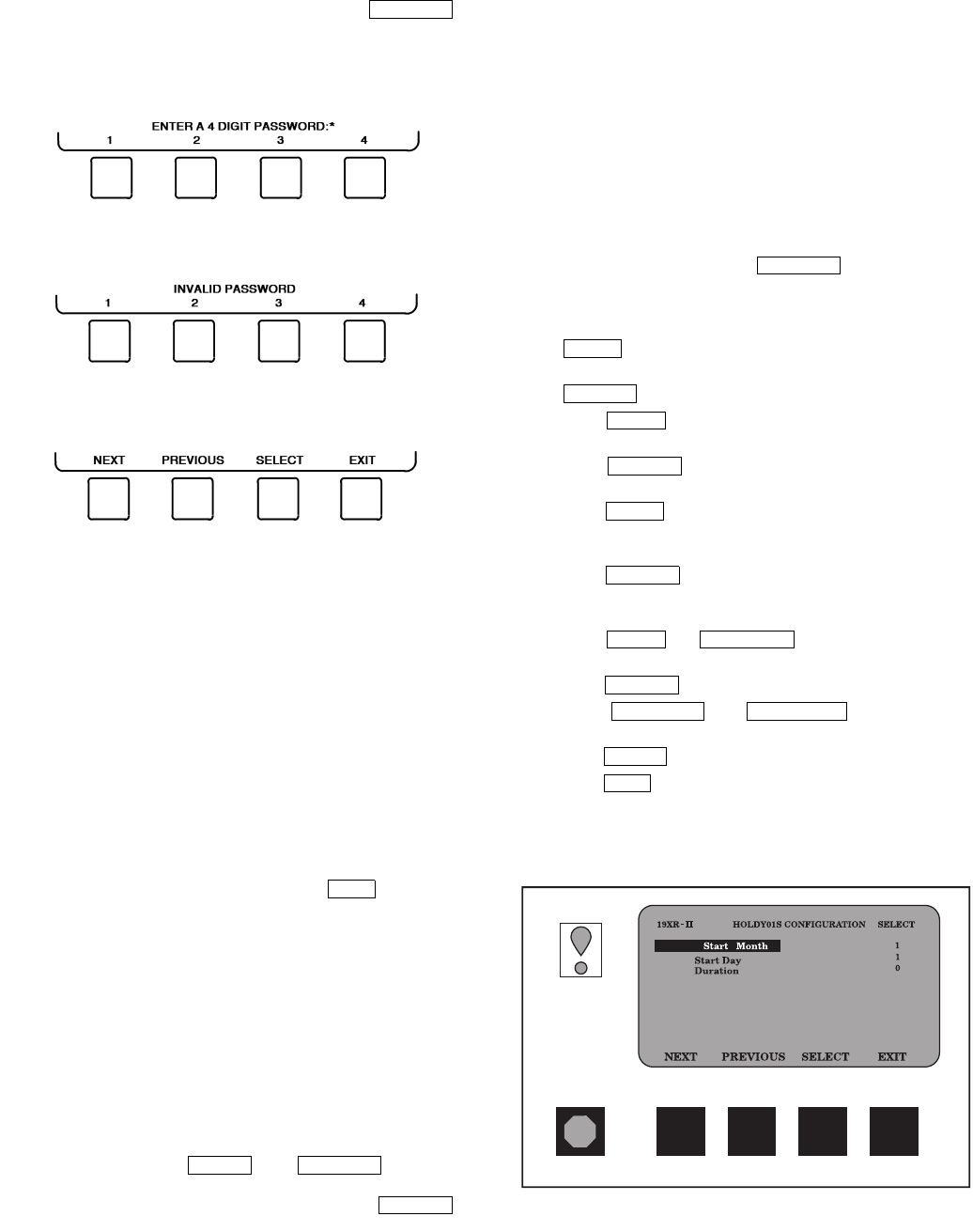
45
Service Operation — An overview of the tables and
screens available for the SERVICE function is shown in
Fig. 18.
TO ACCESS THE SERVICE SCREENS — When the SER-
VICE screens are accessed, a password must be entered.
1. From the main MENU screen, press the
softkey. The softkeys now correspond to the numerals
1, 2, 3, 4.
2. Press the four digits of the password, one at a time. An
asterisk (*) appears as each digit is entered
NOTE: The initial factory-set password is 1-1-1-1. If the
password is incorrect, an error message is displayed
If this occurs, return to Step 1 and try to access the SER-
VICE screens again. If the password is correct, the soft-
key labels change to:
NOTE: The SERVICE screen password can be changed
by entering the CVC/ICVC CONFIGURATION screen
under SERVICE menu. The password is located at the
bottom of the menu.
The CVC/ICVC screen displays the following list of
available SERVICE screens:
• Alarm History
• Control Test
• Control Algorithm Status
• Equipment Configuration
• ISM (Starter) Config Data
• Equipment Service
• Time and Date
• Attach to Network Device
• Log Out of Device
• CVC/ICVC Configuration
See Fig. 18 for additional screens and tables available from
the SERVICE screens listed above. Use the softkey to
return to the main MENU screen.
NOTE: To prevent unauthorized persons from accessing the
CVC/ICVC service screens, the CVC/ICVC automatically
signs off and password-protects itself if a key has not been
pressed for 15 minutes. The sequence is as follows. Fifteen
minutes after the last key is pressed, the default screen dis-
plays, the CVC/ICVC screen light goes out (analogous to a
screen saver), and the CVC/ICVC logs out of the password-
protected SERVICE menu. Other screen and menus, such as
the STATUS screen can be accessed without the password by
pressing the appropriate softkey.
TO LOG OUT OF NETWORK DEVICE — To access this
screen and log out of a network device, from the default CVC/
ICVC screen, press the and softkeys.
Enter the password and, from the SERVICE menu, highlight
LOG OUT OF NETWORK DEVICE and press the
softkey. The CVC/ICVC default screen will now be displayed.
HOLIDAY SCHEDULING (Fig. 25) — The time schedules
may be configured for special operation during a holiday peri-
od. When modifying a time period, the “H” at the end of the
days of the week field signifies that the period is applicable to a
holiday. (See Fig. 19.)
The broadcast function must be activated for the holidays
configured on the HOLIDEF screen to work properly. Access
the BRODEF screen from the EQUIPMENT CONFIGURA-
TION table and select ENABLE to activate function. Note that
when the chiller is connected to a CCN Network, only one
chiller or CCN device can be configured as the broadcast de-
vice. The controller that is configured as the broadcaster is the
device responsible for transmitting holiday, time, and daylight-
savings dates throughout the network.
To access the BRODEF screen, see the SERVICE menu
structure, Fig. 18.
To view or change the holiday periods for up to 18 different
holidays, perform the following operation:
1. At the Menu screen, press to access the Ser-
vice menu.
2. If not logged on, follow the instructions for Attach to Net-
work Device or To Log Out. Once logged on, press
until Equipment Configuration is highlighted.
3. Once Equipment Configuration is highlighted, press
to access.
4. Press until HOLIDAYS is highlighted. This is
the Holiday Definition table.
5. Press to enter the Data Table Select screen.
This screen lists 18 holiday tables.
6. Press to highlight the holiday table that is to be
viewed or changed. Each table is one holiday period,
starting on a specific date, and lasting up to 99 days.
7. Press to access the holiday table. The Config-
uration Select table now shows the holiday start month
and day, and how many days the holiday period will last.
8. Press or to highlight the month,
day, or duration.
9. Press to modify the month, day, or duration.
10. Press or to change the
selected value.
11. Press to save the changes.
12. Press to return to the previous menu.
SERVICE
EXIT
MENU SERVICE
SELECT
SERVICE
NEXT
SELECT
NEXT
SELECT
NEXT
SELECT
NEXT PREVIOUS
SELECT
INCREASE DECREASE
ENTER
EXIT
Fig. 25 — Example of Holiday Period Screen
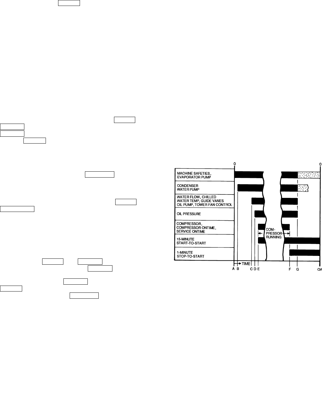
46
START-UP/SHUTDOWN/
RECYCLE SEQUENCE (Fig. 26)
Local Start-Up — Local start-up (or a manual start-up) is
initiated by pressing the menu softkey on the default
CVC/ICVC screen. Local start-up can proceed when the chiller
schedule indicates that the current time and date have been
established as a run time and date, and after the internal
15-minute start-to-start and the 1-minute stop-to-start inhibit
timers have expired. These timers are represented in the START
INHIBIT TIMER and can be viewed on the MAINSTAT screen
and DEFAULT screen. The timer must expire before the chiller
will start. If the timers have not expired the RUN STATUS pa-
rameter on the MAINSTAT screen now reads TIMEOUT.
NOTE: The time schedule is said to be “occupied” if the
OCCUPIED ? parameter on the MAINSTAT screen is set to
YES. For more information on occupancy schedules, see the
sections on Time Schedule Operation (page 20), Occupancy
Schedule (page 34), and To Prevent Accidental Start-Up
(page 65), and Fig. 19.
If the OCCUPIED ? parameter on the MAINSTAT screen
is set to NO, the chiller can be forced to start as follows. From
the default CVC/ICVC screen, press the and
softkeys. Scroll to highlight MAINSTAT. Press the
softkey. Scroll to highlight CHILLER START/STOP.
Press the softkey to override the schedule and start
the chiller.
NOTE: The chiller will continue to run until this forced start is
released, regardless of the programmed schedule. To release
the forced start, highlight CHILLER START/STOP from the
MAINSTAT screen and press the softkey. This
action returns the chiller to the start and stop times established
by the schedule.
The chiller may also be started by overriding the time
schedule. From the default screen, press the and
softkeys. Scroll down and select the current
schedule. Select OVERRIDE, and set the desired override
time.
Another condition for start-up must be met for chillers that
have the REMOTE CONTACTS OPTION on the EQUIP-
MENT SERVICE screen set to ENABLE. For these chillers,
the REMOTE START CONTACT parameter on the MAIN-
STAT screen must be CLOSED. From the CVC/ICVC default
screen, press the and softkeys. Scroll to
highlight MAINSTAT and press the softkey. Scroll
down the MAINSTAT screen to highlight REMOTE START
CONTACT and press the softkey. Then, press the
softkey. To end the override, select REMOTE CON-
TACTS INPUT and press the softkey.
Once local start-up begins, the PIC II performs a series of
pre-start tests to verify that all pre-start alerts and safeties are
within the limits shown in Table 4. The RUN STATUS parame-
ter on the MAINSTAT screen line now reads PRESTART. If a
test is not successful, the start-up is delayed or aborted. If the
tests are successful, the chilled water/brine pump relay energiz-
es, and the MAINSTAT screen line now reads STARTUP.
Five seconds later, the condenser pump relay energizes.
Thirty seconds later the PIC II monitors the chilled water and
condenser water flow devices and waits until the WATER
FLOW VERIFY TIME (operator-configured, default 5 minutes)
expires to confirm flow. After flow is verified, the chilled water
temperature is compared to CONTROL POINT plus 1/2
CHILLED WATER DEADBAND. If the temperature is less
than or equal to this value, the PIC II turns off the condenser
pump relay and goes into a RECYCLE mode.
NOTE: Units equipped with ICVC are not available with fac-
tory installed chilled water or condenser water flow devices
(available as an accessory for use with the CCM Control
board).
If the water/brine temperature is high enough, the start-up
sequence continues and checks the guide vane position. If the
guide vanes are more than 4% open, the start-up waits until the
PIC II closes the vanes. If the vanes are closed and the oil pump
pressure is less than 4 psi (28 kPa), the oil pump relay energiz-
es. The PIC II then waits until the oil pressure (OIL PRESS
VERIFY TIME, operator-configured, default of 40 seconds)
reaches a maximum of 18 psi (124 kPa). After oil pressure is
verified, the PIC II waits 40 seconds, and the compressor start
relay (1CR) energizes to start the compressor.
Compressor ontime and service ontime timers start, and the
compressor STARTS IN 12 HOURS counter and the number of
starts over a 12-hour period counter advance by one.
Failure to verify any of the requirements up to this point will
result in the PIC II aborting the start and displaying the applica-
ble pre-start mode of failure on the CVC/ICVC default screen.
A pre-start failure does not advance the STARTS IN 12 HOURS
counter. Any failure after the 1CR relay has energized results in
a safety shutdown, advances the starts in 12 hours counter by
one, and displays the applicable shutdown status on the CVC/
ICVC display.
LOCAL
MENU
STATUS
SELECT START
RELEASE
MENU
SCHEDULE
MENU STATUS
SELECT
SELECT
CLOSE RELEASE
A—START INITIATED: Pre-start checks are made; evaporator pump
started.
B—Condenser water pump started (5 seconds after A).
C—Water flows verified (30 seconds to 5 minutes maximum after B).
Chilled water temperatures checked against control point. Guide
vanes checked for closure. Oil pump started; tower fan control
enabled.
D—Oil pressure verified (15 seconds minimum, 300 seconds maximum
after C).
E—Compressor motor starts; compressor ontime and service ontime
start, 15-minute inhibit timer starts (10 seconds after D), total com-
pressor starts advances by one, and the number of starts over a
12-hour period advances by one.
F—SHUTDOWN INITIATED — Compressor motor stops; compressor
ontime and service ontime stop, and 1-minute inhibit timer starts.
G—Oil pump and evaporator pumps deenergized (60 seconds after F).
Condenser pump and tower fan control may continue to operate if
condenser pressure is high. Evaporator pump may continue if in
RECYCLE mode.
O/A —Restart permitted (both inhibit timers expired: minimum of 15 minutes
after E; minimum of 1 minute after F).
Fig. 26 — Control Sequence
47
Shutdown Sequence — Chiller shutdown begins if
any of the following occurs:
•the STOP button is pressed for at least one second (the
alarm light blinks once to confirm the stop command)
•a recycle condition is present (see Chilled Water Recycle
Mode section)
•the time schedule has gone into unoccupied mode
•the chiller protective limit has been reached and chiller is
in alarm
•the start/stop status is overridden to stop from the CCN
network or the CVC/ICVC
When a stop signal occurs, the shutdown sequence first
stops the compressor by deactivating the start relay (1CR). A
status message of “SHUTDOWN IN PROGRESS, COM-
PRESSOR DEENERGIZED” is displayed, and the compres-
sor ontime and service ontime stop. The guide vanes are then
brought to the closed position. The oil pump relay and the
chilled water/brine pump relay shut down 60 seconds after the
compressor stops. The condenser water pump shuts down at
the same time if the ENTERING CONDENSER WATER tem-
perature is greater than or equal to 115 F (46.1 C) and the
CONDENSER REFRIG TEMP is greater than the CONDENS-
ER FREEZE POINT plus 5 F (–15.0 C). The stop-to-start timer
now begins to count down. If the start-to-start timer value is
still greater than the value of the start-to-stop timer, then this
time displays on the CVC/ICVC.
Certain conditions that occur during shutdown can change
this sequence.
•If the AVERAGE LINE CURRENT is greater than 5%
after shutdown, or the starter contacts remain energized,
the oil pump and chilled water pump remain energized
and the alarm is displayed.
•The condenser pump shuts down when the CON-
DENSER PRESSURE is less than the COND PRESS
OVERRIDE threshold minus 3.5 psi (24.1 kPa) and the
CONDENSER REFRIG TEMP is less than or equal to the
ENTERING CONDENSER WATER temperature plus
3° F (–1.6° C).
•If the chiller shuts down due to low refrigerant tempera-
ture, the chilled water pump continues to run until the
LEAVING CHILLED WATER temperature is greater than
the CONTROL POINT temperature, plus 5° F (3° C).
Automatic Soft Stop Amps Threshold — The soft
stop amps threshold feature closes the guide vanes of the com-
pressor automatically if a non-recycle, non-alarm stop signal
occurs before the compressor motor is deenergized.
If the STOP button is pressed, the guide vanes close to a
preset amperage percent until the guide vane is less than 4%
open or 4 minutes have passed. The compressor then shuts off.
If the chiller enters an alarm state or if the compressor enters
a RECYCLE mode, the compressor deenergizes immediately.
To activate the soft stop amps threshold feature, scroll to the
bottom of OPTIONS screen on the CVC/ICVC. Use the
or softkey to set the SOFT STOP
AMPS THRESHOLD parameter to the percent of amps at
which the motor will shut down. The default setting is 100%
amps (no soft stop). The range is 40 to 100%.
When the soft stop amps threshold feature is being applied,
a status message, “SHUTDOWN IN PROGRESS, COM-
PRESSOR UNLOADING” displays on the CVC/ICVC.
The soft stop amps threshold function can be terminated and
the compressor motor deenergized immediately by depressing
the STOP button twice.
Chilled Water Recycle Mode — The chiller may
cycle off and wait until the load increases to restart when the
compressor is running in a lightly loaded condition. This cy-
cling is normal and is known as “recycle.” A recycle shutdown
is initiated when any of the following conditions are true:
•the chiller is in LCW control, the difference between the
LEAVING CHILLED WATER temperature and ENTER-
ING CHILLED WATER temperature is less than the
RECYCLE SHUTDOWN DELTA T (found in the
SETUP1 table) the LEAVING CHILLED WATER tem-
perature is 5° F (2.8° C) below the CONTROL POINT,
the CONTROL POINT has not increased in the last
5 minutes and ICE BUILD is not active.
•the ECW CONTROL OPTION is enabled, the difference
between the ENTERING CHILLED WATER temperature
and the LEAVING CHILLED WATER temperature is less
than the RECYCLE SHUTDOWN DELTA T (found in the
SETUP1 table), the ENTERING CHILLED WATER tem-
perature is 5° F (2.8° C) below the CONTROL POINT,
and the CONTROL POINT has not increased in the last
5 minutes.
•the LEAVING CHILLED WATER temperature is within
3° F (2° C) of the EVAP REFRIG TRIPPOINT.
When the chiller is in RECYCLE mode, the chilled water
pump relay remains energized so the chilled water temperature
can be monitored for increasing load. The recycle control uses
RESTART DELTA T to check when the compressor should be
restarted. This is an operator-configured function which de-
faults to 5° F (3° C). This value can be viewed or modified on
the SETUP1 table. The compressor will restart when the chiller
is:
•in LCW CONTROL and the LEAVING CHILLED
WATER temperature is greater than the CONTROL
POINT plus the RECYCLE RESTART DELTA T.
•in ECW CONTROL and the ENTERING CHILLED
WATER temperature is greater than the CONTROL
POINT plus the RECYCLE RESTART DELTA T.
Once these conditions are met, the compressor initiates a
start-up with a normal start-up sequence.
An alert condition may be generated if 5 or more recycle
start-ups occur in less than 4 hours. Excessive recycling can
reduce chiller life; therefore, compressor recycling due to ex-
tremely low loads should be reduced.
To reduce compressor recycling, use the time schedule to
shut the chiller down during known low load operation period,
or increase the chiller load by running the fan systems. If the
hot gas bypass is installed, adjust the values to ensure that hot
gas is energized during light load conditions. Increase the
RECYCLE RESTART DELTA T on the SETUP1 table to
lengthen the time between restarts.
The chiller should not be operated below design minimum
load without a hot gas bypass installed.
Safety Shutdown — A safety shutdown is identical to
a manual shutdown with the exception that, during a safety
shutdown, the CVC/ICVC displays the reason for the shut-
down, the alarm light blinks continuously, and the spare alarm
contacts are energized.
After a safety shutdown, the softkey must be
pressed to clear the alarm. If the alarm condition is still present,
the alarm light continues to blink. Once the alarm is cleared,
the operator must press the or softkeys to re-
start the chiller.
INCREASE DECREASE
RESET
CCN LOCAL
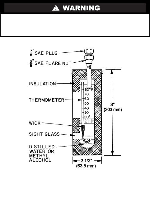
48
BEFORE INITIAL START-UP
Job Data Required
•list of applicable design temperatures and pressures
(product data submittal)
•chiller certified prints
•starting equipment details and wiring diagrams
•diagrams and instructions for special controls or options
•19XR Installation Instructions
•pumpout unit instructions
Equipment Required
•mechanic’s tools (refrigeration)
•digital volt-ohmmeter (DVM)
•clamp-on ammeter
•electronic leak detector
•absolute pressure manometer or wet-bulb vacuum indi-
cator (Fig. 27)
•500-v insulation tester (megohmmeter) for compressor
motors with nameplate voltage of 600 v or less, or a
5000-v insulation tester for compressor motor rated
above 600 v
Using the Optional Storage Tank and Pump-
out System — Refer to Chillers with Storage Tanks sec-
tion, page 69 for pumpout system preparation, refrigerant
transfer, and chiller evacuation.
Remove Shipping Packaging — Remove any pack-
aging material from the control center, power panel, guide vane
actuator, motor cooling and oil reclaim solenoids, motor and
bearing temperature sensor covers, and the factory-mounted
starter.
Open Oil Circuit Valves — Check to ensure the oil fil-
ter isolation valves (Fig. 4) are open by removing the valve cap
and checking the valve stem.
Tighten All Gasketed Joints and Guide Vane
Shaft Packing — Gaskets and packing normally relax by
the time the chiller arrives at the jobsite. Tighten all gasketed
joints and the guide vane shaft packing to ensure a leak-tight
chiller.
Check Chiller Tightness — Figure 28 outlines the
proper sequence and procedures for leak testing.
The 19XR chillers are shipped with the refrigerant con-
tained in the condenser shell and the oil charge in the compres-
sor. The cooler is shipped with a 15 psig (103 kPa) refrigerant
charge. Units may be ordered with the refrigerant shipped sepa-
rately, along with a 15 psig (103 kPa) nitrogen-holding charge
in each vessel.
To determine if there are any leaks, the chiller should be
charged with refrigerant. Use an electronic leak detector to
check all flanges and solder joints after the chiller is pressur-
ized. If any leaks are detected, follow the leak test procedure.
If the chiller is spring isolated, keep all springs blocked in
both directions to prevent possible piping stress and damage
during the transfer of refrigerant from vessel to vessel during
the leak test process, or any time refrigerant is being trans-
ferred. Adjust the springs when the refrigerant is in operating
condition and the water circuits are full.
Refrigerant Tracer — Carrier recommends the use of an
environmentally acceptable refrigerant tracer for leak testing
with an electronic detector or halide torch.
Ultrasonic leak detectors can also be used if the chiller is
under pressure.
Do not use air or oxygen as a means of pressurizing
the chiller. Mixtures of HFC-134a and air can undergo
combustion.
Fig. 27 — Typical Wet-Bulb Type
Vacuum Indicator

49
Fig. 28 — 19XR Leak Test Procedures
50
Leak Test Chiller — Due to regulations regarding refrig-
erant emissions and the difficulties associated with separating
contaminants from the refrigerant, Carrier recommends the
following leak test procedure. See Fig. 28 for an outline of the
leak test procedure. Refer to Fig. 29 and 30 during pumpout
procedures and Tables 5A and 5B for refrigerant pressure/
temperature values.
1. If the pressure readings are normal for the chiller
condition:
a. Evacuate the holding charge from the vessels, if
present.
b. Raise the chiller pressure, if necessary, by adding
refrigerant until pressure is at the equivalent satu-
rated pressure for the surrounding temperature.
Follow the pumpout procedures in the Transfer
Refrigerant from Pumpout Storage Tank to Chiller
section, Steps 1a - e, page 69.
c. Leak test chiller as outlined in Steps 3 - 9.
2. If the pressure readings are abnormal for the chiller
condition:
a. Prepare to leak test chillers shipped with refriger-
ant (Step 2h).
b. Check for large leaks by connecting a nitrogen bottle
and raising the pressure to 30 psig (207 kPa). Soap
test all joints. If the test pressure holds for 30 minutes,
prepare the test for small leaks (Steps 2g - h).
c. Plainly mark any leaks that are found.
d. Release the pressure in the system.
e. Repair all leaks.
f. Retest the joints that were repaired.
g. After successfully completing the test for large
leaks, remove as much nitrogen, air, and moisture
as possible, given the fact that small leaks may be
present in the system. This can be accomplished by
following the dehydration procedure, outlined in
the Chiller Dehydration section, page 53.
h. Slowly raise the system pressure to a maximum of
160 psig (1103 kPa) but no less than 35 psig
(241 kPa) for HFC-134a by adding refrigerant.
Proceed with the test for small leaks (Steps 3-9).
3. Check the chiller carefully with an electronic leak detec-
tor, halide torch, or soap bubble solution.
4. Leak Determination — If an electronic leak detector indi-
cates a leak, use a soap bubble solution, if possible, to
confirm. Total all leak rates for the entire chiller. Leakage
at rates greater than 1 lb./year (0.45 kg/year) for the entire
chiller must be repaired. Note the total chiller leak rate on
the start-up report.
5. If no leak is found during the initial start-up procedures,
complete the transfer of refrigerant gas from the pumpout
storage tank to the chiller (see Transfer Refrigerant from
Pumpout Storage Tank to Chiller section, page 69). Re-
test for leaks.
6. If no leak is found after a retest:
a. Transfer the refrigerant to the pumpout storage
tank and perform a standing vacuum test as out-
lined in the Standing Vacuum Test section, below.
b. If the chiller fails the standing vacuum test, check
for large leaks (Step 2b).
c. If the chiller passes the standing vacuum test,
dehydrate the chiller. Follow the procedure in
the Chiller Dehydration section. Charge the chiller
with refrigerant (see Transfer Refrigerant from
Pumpout Storage Tank to Chiller section,
page 69).
7. If a leak is found after a retest, pump the refrigerant back
into the pumpout storage tank or, if isolation valves are
present, pump the refrigerant into the non-leaking
vessel (see Pumpout and Refrigerant Transfer procedures
section).
8. Transfer the refrigerant until the chiller pressure is at
18 in. Hg (40 kPa absolute).
9. Repair the leak and repeat the procedure, beginning from
Step 2h, to ensure a leak-tight repair. (If the chiller is
opened to the atmosphere for an extended period, evacu-
ate it before repeating the leak test.)
Standing Vacuum Test — When performing the
standing vacuum test or chiller dehydration, use a manometer
or a wet bulb indicator. Dial gages cannot indicate the small
amount of acceptable leakage during a short period of time.
1. Attach an absolute pressure manometer or wet bulb indi-
cator to the chiller.
2. Evacuate the vessel (see Pumpout and Refrigerant Trans-
fer Procedures section, page 67) to at least 18 in. Hg vac,
ref 30-in. bar (41 kPa), using a vacuum pump or the
pump out unit.
3. Valve off the pump to hold the vacuum and record the
manometer or indicator reading.
4. a. If the leakage rate is less than 0.05 in. Hg (0.17 kPa) in
24 hours, the chiller is sufficiently tight.
b. If the leakage rate exceeds 0.05 in. Hg (0.17 kPa) in
24 hours, repressurize the vessel and test for leaks.
If refrigerant is available in the other vessel, pressur-
ize by following Steps 2-10 of Return Chiller To
Normal Operating Conditions section, page 71. If
not, use nitrogen and a refrigerant tracer. Raise the
vessel pressure in increments until the leak is
detected. If refrigerant is used, the maximum gas
pressure is approximately 70 psig (483 kPa) for
HFC-134a at normal ambient temperature. If nitro-
gen is used, limit the leak test pressure to 230 psig
(1585 kPa) maximum.
5. Repair the leak, retest, and proceed with dehydration.
Never charge liquid refrigerant into the chiller if the pres-
sure in the chiller is less than 35 psig (241 kPa) for
HFC-134a. Charge as a gas only, with the cooler and con-
denser pumps running, until this pressure is reached, using
PUMPDOWN LOCKOUT and TERMINATE LOCK-
OUT mode on the PIC II. Flashing of liquid refrigerant at
low pressures can cause tube freeze-up and considerable
damage.
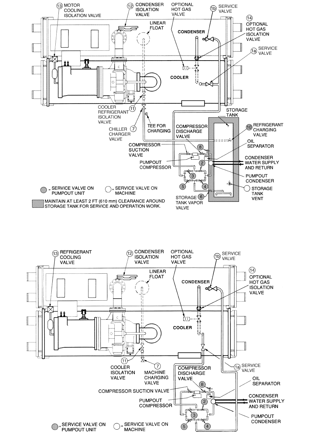
51
Fig. 29 — Typical Optional Pumpout System Piping Schematic with Storage Tank
Fig. 30 — Typical Optional Pumpout System Piping Schematic without Storage Tank

52
Table 5A — HFC-134a Pressure —
Temperature (F)
Table 5B — HFC-134a Pressure —
Temperature (C)
TEMPERATURE,
F
PRESSURE
(psig)
06.50
27.52
48.60
69.66
810.79
10 11.96
12 13.17
14 14.42
16 15.72
18 17.06
20 18.45
22 19.88
24 21.37
26 22.90
28 24.48
30 26.11
32 27.80
34 29.53
36 31.32
38 33.17
40 35.08
42 37.04
44 39.06
46 41.14
48 43.28
50 45.48
52 47.74
54 50.07
56 52.47
58 54.93
60 57.46
62 60.06
64 62.73
66 65.47
68 68.29
70 71.18
72 74.14
74 77.18
76 80.30
78 83.49
80 86.17
82 90.13
84 93.57
86 97.09
88 100.70
90 104.40
92 108.18
94 112.06
96 116.02
98 120.08
100 124.23
102 128.47
104 132.81
106 137.25
108 141.79
110 146.43
112 151.17
114 156.01
116 160.96
118 166.01
120 171.17
122 176.45
124 181.83
126 187.32
128 192.93
130 198.66
132 204.50
134 210.47
136 216.55
138 222.76
140 229.09
TEMPERATURE,
C
PRESSURE
(kPa)
–18.0 44.8
–16.7 51.9
–15.6 59.3
–14.4 66.6
–13.3 74.4
–12.2 82.5
–11.1 90.8
–10.0 99.4
–8.9 108.0
–7.8 118.0
–6.7 127.0
–5.6 137.0
–4.4 147.0
–3.3 158.0
–2.2 169.0
–1.1 180.0
0.0 192.0
1.1 204.0
2.2 216.0
3.3 229.0
4.4 242.0
5.0 248.0
5.6 255.0
6.1 261.0
6.7 269.0
7.2 276.0
7.8 284.0
8.3 290.0
8.9 298.0
9.4 305.0
10.0 314.0
11.1 329.0
12.2 345.0
13.3 362.0
14.4 379.0
15.6 396.0
16.7 414.0
17.8 433.0
18.9 451.0
20.0 471.0
21.1 491.0
22.2 511.0
23.3 532.0
24.4 554.0
25.6 576.0
26.7 598.0
27.8 621.0
28.9 645.0
30.0 669.0
31.1 694.0
32.2 720.0
33.3 746.0
34.4 773.0
35.6 800.0
36.7 828.0
37.8 857.0
38.9 886.0
40.0 916.0
41.1 946.0
42.2 978.0
43.3 1010.0
44.4 1042.0
45.6 1076.0
46.7 1110.0
47.8 1145.0
48.9 1180.0
50.0 1217.0
51.1 1254.0
52.2 1292.0
53.3 1330.0
54.4 1370.0
55.6 1410.0
56.7 1451.0
57.8 1493.0
58.9 1536.0
60.0 1580.0
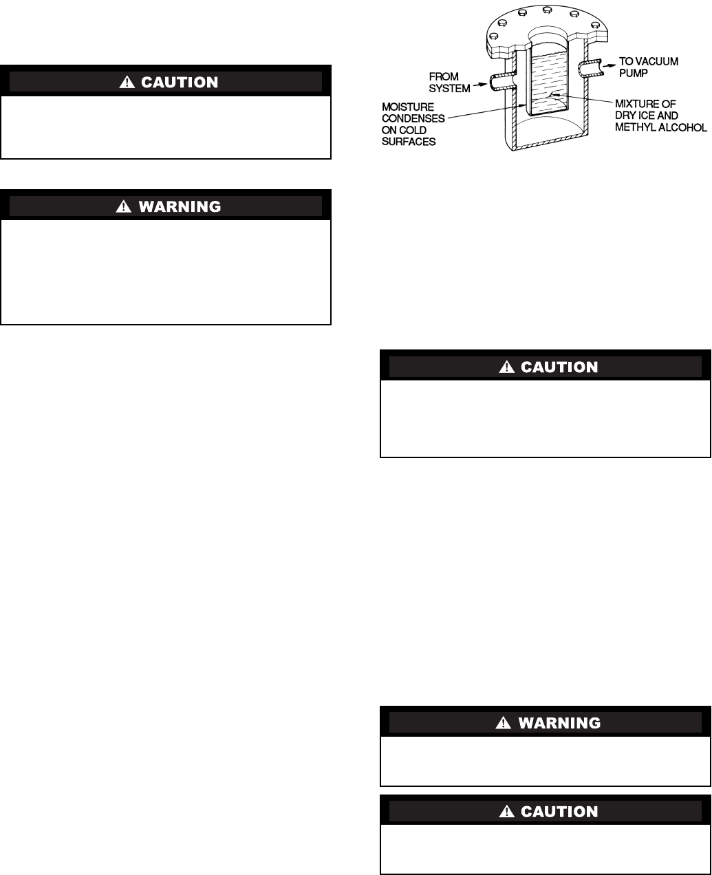
53
Chiller Dehydration — Dehydration is recommended if
the chiller has been open for a considerable period of time, if
the chiller is known to contain moisture, or if there has been a
complete loss of chiller holding charge or refrigerant pressure.
Dehydration can be done at room temperatures. Using a
cold trap (Fig. 31) may substantially reduce the time required
to complete the dehydration. The higher the room temperature,
the faster dehydration takes place. At low room temperatures, a
very deep vacuum is required to boil off any moisture. If low
ambient temperatures are involved, contact a qualified service
representative for the dehydration techniques required.
Perform dehydration as follows:
1. Connect a high capacity vacuum pump (5 cfm [.002 m3/s]
or larger is recommended) to the refrigerant charging
valve (Fig. 2). Tubing from the pump to the chiller should
be as short in length and as large in diameter as possible to
provide least resistance to gas flow.
2. Use an absolute pressure manometer or a wet bulb vacu-
um indicator to measure the vacuum. Open the shutoff
valve to the vacuum indicator only when taking a read-
ing. Leave the valve open for 3 minutes to allow the indi-
cator vacuum to equalize with the chiller vacuum.
3. If the entire chiller is to be dehydrated, open all isolation
valves (if present).
4. With the chiller ambient temperature at 60 F (15.6 C) or
higher, operate the vacuum pump until the manometer
reads 29.8 in. Hg vac, ref 30 in. bar. (0.1 psia)
(–100.61 kPa) or a vacuum indicator reads 35 F (1.7 C).
Operate the pump an additional 2 hours.
Do not apply a greater vacuum than 29.82 in. Hg vac
(757.4 mm Hg) or go below 33 F (.56 C) on the wet bulb
vacuum indicator. At this temperature and pressure, iso-
lated pockets of moisture can turn into ice. The slow rate
of evaporation (sublimation) of ice at these low tempera-
tures and pressures greatly increases dehydration time.
5. Valve off the vacuum pump, stop the pump, and record
the instrument reading.
6. After a 2-hour wait, take another instrument reading. If
the reading has not changed, dehydration is complete. If
the reading indicates vacuum loss, repeat Steps 4 and 5.
7. If the reading continues to change after several attempts,
perform a leak test up to the maximum 160 psig
(1103 kPa) pressure. Locate and repair the leak, and re-
peat dehydration.
Inspect Water Piping — Refer to piping diagrams pro-
vided in the certified drawings and the piping instructions in
the 19XR Installation Instructions manual. Inspect the piping to
the cooler and condenser. Be sure that the flow directions are
correct and that all piping specifications have been met.
Piping systems must be properly vented with no stress on
waterbox nozzles and covers. Water flows through the cooler
and condenser must meet job requirements. Measure the pres-
sure drop across the cooler and the condenser.
Check Optional Pumpout Compressor Water
Piping — If the optional pumpout storage tank and/or
pumpout system are installed, check to ensure the pumpout
condenser water has been piped in. Check for field-supplied
shutoff valves and controls as specified in the job data. Check
for refrigerant leaks on field-installed piping. See Fig. 29
and 30.
Check Relief Valves — Be sure the relief valves have
been piped to the outdoors in compliance with the latest edition
of ANSI/ASHRAE Standard 15 and applicable local safety
codes. Piping connections must allow for access to the valve
mechanism for periodic inspection and leak testing.
The 19XR relief valves are set to relieve at the 185 psig
(1275 kPa) chiller design pressure.
Inspect Wiring
1. Examine the wiring for conformance to the job wiring di-
agrams and all applicable electrical codes.
Do not start or megohm-test the compressor motor or oil
pump motor, even for a rotation check, if the chiller is
under dehydration vacuum. Insulation breakdown and
severe damage may result.
Inside-delta type starters must be disconnected by an isola-
tion switch before placing the machine under a vacuum
because one lead of each phase is live with respect to
ground even though there is not a complete circuit to run
the motor. To be safe, isolate any starter before evacuating
the chiller if you are not sure if there are live leads to the
hermetic motor.
Water must be within design limits, clean, and treated to
ensure proper chiller performance and to reduce the poten-
tial of tube damage due to corrosion, scaling, or erosion.
Carrier assumes no responsibility for chiller damage result-
ing from untreated or improperly treated water.
Do not check the voltage supply without proper equipment
and precautions. Serious injury may result. Follow power
company recommendations.
Do not apply any kind of test voltage, even for a rotation
check, if the chiller is under a dehydration vacuum. Insula-
tion breakdown and serious damage may result.
Fig. 31 — Dehydration Cold Trap

54
2. On low-voltage compressors (600 v or less) connect a
voltmeter across the power wires to the compressor start-
er and measure the voltage. Compare this reading to the
voltage rating on the compressor and starter nameplates.
3. Compare the ampere rating on the starter nameplate to
rating on the compressor nameplate. The overload trip
amps must be 108% to 120% of the rated load amps.
4. The starter for a centrifugal compressor motor must
contain the components and terminals required for PIC II
refrigeration control. Check the certified drawings.
5. Check the voltage to the following components and
compare it to the nameplate values: oil pump contact,
pumpout compressor starter, and power panel.
6. Ensure that fused disconnects or circuit breakers have
been supplied for the oil pump, power panel, and
pumpout unit.
7. Ensure all electrical equipment and controls are properly
grounded in accordance with job drawings, certified
drawings, and all applicable electrical codes.
8. Ensure the customer’s contractor has verified proper op-
eration of the pumps, cooling tower fans, and associated
auxiliary equipment. This includes ensuring motors are
properly lubricated and have proper electrical supply and
proper rotation.
9. For field-installed starters only, test the chiller compres-
sor motor and its power lead insulation resistance with a
500-v insulation tester such as a megohmmeter. (Use a
5000-v tester for motors rated over 600 v.) Factory-
mounted starters do not require a megohm test.
a. Open the starter main disconnect switch and follow
lockout/tagout rules.
b. With the tester connected to the motor leads, take
10-second and 60-second megohm readings as
follows:
6-Lead Motor — Tie all 6 leads together and test
between the lead group and ground. Next tie the
leads in pairs: 1 and 4, 2 and 5, and 3 and 6. Test
between each pair while grounding the third pair.
3-Lead Motor — Tie terminals 1, 2, and 3 together
and test between the group and ground.
c. Divide the 60-second resistance reading by the
10-second reading. The ratio, or polarization
index, must be one or higher. Both the 10- and
60-second readings must be at least 50 megohms.
If the readings on a field-installed starter are unsat-
isfactory, repeat the test at the motor with the
power leads disconnected. Satisfactory readings in
this second test indicate the fault is in the power
leads.
NOTE: Unit-mounted starters do not have to be
megohm tested.
10. Tighten all wiring connections to the plugs on the ISM
and CCM modules.
11. On chillers with free-standing starters, inspect the power
panel to ensure that the contractor has fed the wires into
the bottom of the panel. Wiring into the top of the panel
can cause debris to fall into the contactors. Clean and in-
spect the contactors if this has occurred.
Carrier Comfort Network Interface — The Carrier
Comfort Network (CCN) communication bus wiring is sup-
plied and installed by the electrical contractor. It consists of
shielded, 3-conductor cable with drain wire.
The system elements are connected to the communication
bus in a daisy chain arrangement. The positive pin of each sys-
tem element communication connector must be wired to the
positive pins of the system element on either side of it. The
negative pins must be wired to the negative pins. The signal
ground pins must be wired to the signal ground pins. See instal-
lation manual.
NOTE: Conductors and drain wire must be 20 AWG
(American Wire Gage) minimum stranded, tinned copper.
Individual conductors must be insulated with PVC, PVC/
nylon, vinyl, Teflon, or polyethylene. An aluminum/polyester
100% foil shield and an outer jacket of PVC, PVC/nylon,
chrome vinyl, or Teflon with a minimum operating tempera-
ture range of –4 F to 140 F (–20 C to 60 C) is required. See
table below for cables that meet the requirements.
When connecting the CCN communication bus to a system
element, a color code system for the entire network is recom-
mended to simplify installation and checkout. The following
color code is recommended:
Check Starter
Use the instruction and service manual supplied by the start-
er manufacturer to verify the starter has been installed correct-
ly, to set up and calibrate the starter, and for complete trouble-
shooting information.
If the motor starter is a solid-state starter, the motor leads
must be disconnected from the starter before an insulation
test is performed. The voltage generated from the tester can
damage the starter solid-state components.
MANUFACTURER CABLE NO.
Alpha 2413 or 5463
American A22503
Belden 8772
Columbia 02525
SIGNAL TYPE
CCN BUS
CONDUCTOR
INSULATION
COLOR
CCN TERMINAL
CONNECTION
+Red RED (+)
Ground White WHITE (G)
–Black BLACK (–)
BE AWARE that certain automatic start arrangements can
engage the starter. Open the disconnect ahead of the starter
in addition to shutting off the chiller or pump.
The main disconnect on the starter front panel may not
deenergize all internal circuits. Open all internal and
remote disconnects before servicing the starter.

55
MECHANICAL STARTER
1. Check all field wiring connections for tightness, clear-
ance from moving parts, and correct connection.
2. Check the contactor(s) to ensure they move freely. Check
the mechanical interlock between contactors to ensure
that 1S and 2M contactors cannot be closed at the same
time. Check all other electro-mechanical devices, such as
relays, for free movement. If the devices do not move
freely, contact the starter manufacturer for replacement
components.
3. Reapply starter control power (not main chiller power) to
check the electrical functions.
Ensure the starter (with relay 1CR closed) goes through a
complete and proper start cycle.
BENSHAW, INC. RediStart MICRO™ SOLID-STATE
STARTER
1. Ensure all wiring connections are properly terminated to
the starter.
2. Verify the ground wire to the starter is installed properly
and is sufficient size.
3. Verify the motors are properly grounded to the starter.
4. Verify the proper ac input voltage is brought into the start-
er according to the certified drawings.
5. Apply power to the starter
VFD STARTER
1. Turn off unit, tag and lock disconnects and wait 5 minutes.
2. Verify that the DC voltage is zero.
3. Ensure there is adequate clearance around the drive.
4. Verify that the wiring to the terminal strip and power ter-
minals is correct.
5. Verify that wire size is within the terminal specification
and the wires are secure.
6. Inspect the field supplied branch circuit protection is
properly rated and installed.
7. Verify that the system is properly grounded.
8. Inspect all liquid cooling connections for leaks.
Oil Charge — The oil charge for the 19XR compressor de-
pends on the compressor Frame size:
•Frame 2 compressor — 5 gal (18.9 L)
•Frame 3 compressor — 8 gal (30 L)
•Frame 4 compressor — 10 gal (37.8 L)
•Frame 5 compressor — 18 gal (67.8 L)
The chiller is shipped with oil in the compressor. When the
sump is full, the oil level should be no higher than the middle
of the upper sight glass, and minimum level is the bottom
of the lower sight glass (Fig. 2). If oil is added, it must meet
Carrier’s specification for centrifugal compressor use as de-
scribed in the Oil Specification section. Charge the oil through
the oil charging valve located near the bottom of the transmis-
sion housing (Fig. 2). The oil must be pumped from the oil
container through the charging valve due to higher refrigerant
pressure. The pumping device must be able to lift from 0 to
200 psig (0 to 1380 kPa) or above unit pressure. Oil should
only be charged or removed when the chiller is shut down.
Power Up the Controls and Check the Oil
Heater — Ensure that an oil level is visible in the compres-
sor before energizing the controls. A circuit breaker in the start-
er energizes the oil heater and the control circuit. When first
powered, the CVC/ICVC should display the default screen
within a short period of time.
The oil heater is energized by powering the control circuit.
This should be done several hours before start-up to minimize
oil-refrigerant migration. The oil heater is controlled by the
PIC II and is powered through a contactor in the power panel.
Starters contain a separate circuit breaker to power the heater
and the control circuit. This arrangement allows the heater to
energize when the main motor circuit breaker is off for service
work or extended shutdowns. The oil heater relay status (OIL
HEATER RELAY) can be viewed on the COMPRESS table on
the CVC/ICVC. Oil sump temperature can be viewed on the
CVC/ICVC default screen.
SOFTWARE VERSION — The software part number is la-
beled on the backside of the CVC/ICVC module. The software
version also appears on the CVC/ICVC configuration screen as
the last two digits of the software part number.
Software Configuration
As the 19XR unit is configured, all configuration settings
should be written down. A log, such as the one shown on pages
CL-1 to CL-16, provides a list for configuration values.
Input the Design Set Points — Access the CVC/
ICVC set point screen and view/modify the base demand limit
set point, and either the LCW set point or the ECW set point.
The PIC II can control a set point to either the leaving or enter-
ing chilled water. This control method is set in the EQUIP-
MENT SERVICE (TEMP_CTL) table.
Input the Local Occupied Schedule (OCCPC01S) —
Access the schedule OCCPC01S screen on the CVC/ICVC
and set up the occupied time schedule according to the custom-
er’s requirements. If no schedule is available, the default is fac-
tory set for 24 hours occupied, 7 days per week including
holidays.
For more information about how to set up a time schedule,
see the Controls section, page 10.
The CCN Occupied Schedule (OCCPC03S) should be con-
figured if a CCN system is being installed or if a secondary
time schedule is needed.
NOTE: The default CCN Occupied Schedule OCCPC03S is
configured to be unoccupied.
Input Service Configurations — The following con-
figurations require the CVC/ICVC screen to be in the SER-
VICE portion of the menu.
•password
•input time and date
•CVC/ICVC configuration
•service parameters
•equipment configuration
•automated control test
PASSWORD — When accessing the SERVICE tables, a pass-
word must be entered. All CVC/ICVC are initially set for a
password of 1-1-1-1.
INPUT TIME AND DATE — Access the TIME AND DATE
table on the SERVICE menu. Input the present time of day,
date, and day of the week. The HOLIDAY TODAY parameter
should only be configured to YES if the present day is a
holiday.
This equipment is at line voltage when AC power is con-
nected. Pressing the STOP button does not remove voltage. Do not operate the chiller before the control configurations
have been checked and a Control Test has been
satisfactorily completed. Protection by safety controls can-
not be assumed until all control configurations have been
confirmed.
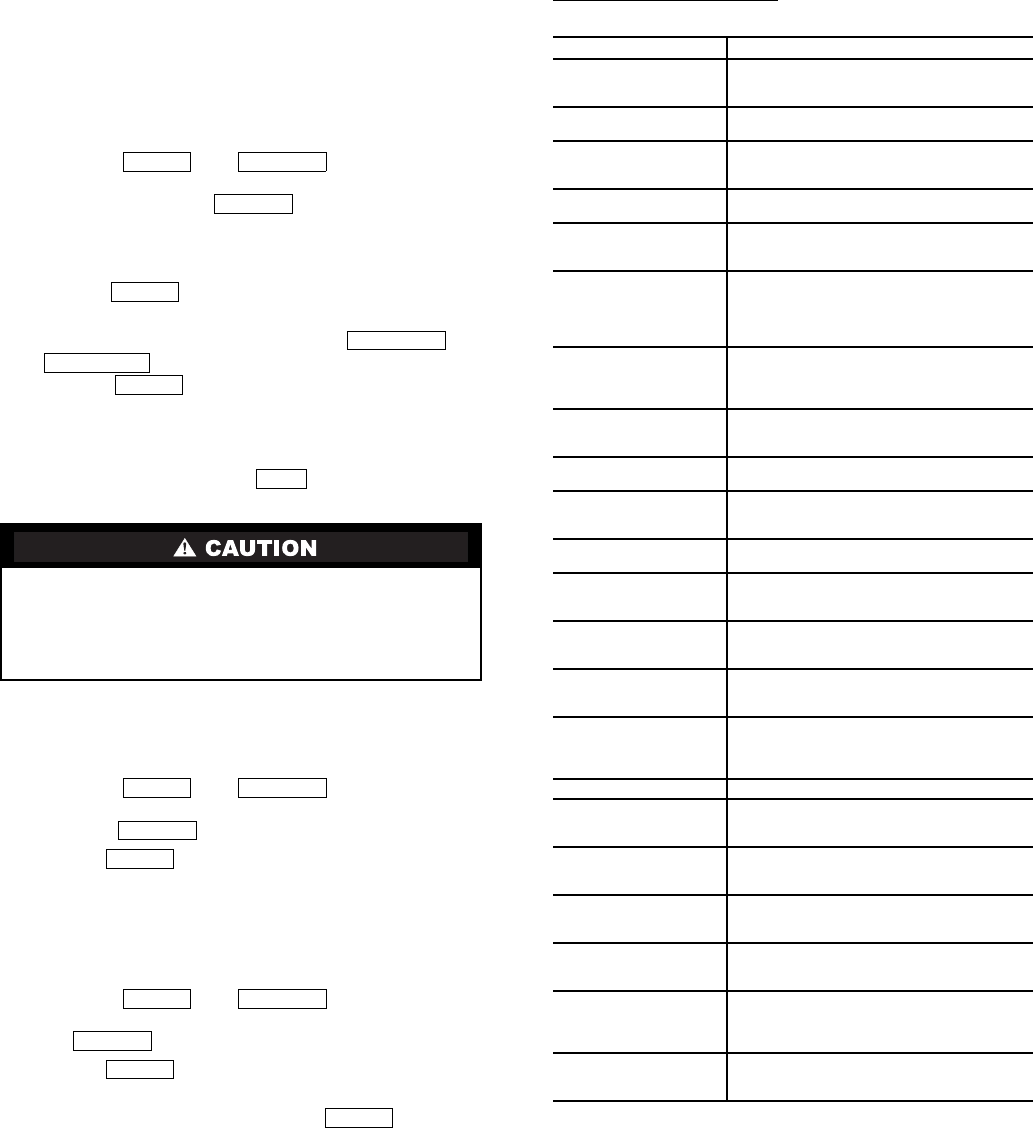
56
NOTE: Because a schedule is integral to the chiller control
sequence, the chiller will not start until the time and date have
been set.
CHANGE CVC/ICVC CONFIGURATION IF NECES-
SARY — From the SERVICE table, access the CVC/ICVC
CONFIGU-RATION screen. From there, view or modify the
CVC/ICVC CCN address, change to English or SI units, and
change the password. If there is more than one chiller at the
jobsite, change the CVC/ICVC address on each chiller so that
each chiller has its own address. Note and record the new
address. Change the screen to SI units as required, and change
the password if desired.
TO CHANGE THE PASSWORD — The password may be
changed from the CVC/ICVC CONFIGURATION screen.
1. Press the and softkeys. Enter the
current password and highlight CVC/ICVC CONFIGU-
RATION. Press the softkey. Only the last
5 entries on the CVC/ICVC CONFIG screen can be
changed: BUS #, ADDRESS #, BAUD RATE, US IMP/
METRIC, and PASSWORD.
2. Use the softkey to scroll to PASSWORD. The
first digit of the password is highlighted on the screen.
3. To change the digit, press the or
softkey. When the desired digit is seen,
press the softkey.
4. The next digit is highlighted. Change it, and the third and
fourth digits in the same way the first was changed.
5. After the last digit is changed, the CVC/ICVC goes to the
BUS parameter. Press the softkey to leave that
screen and return to the SERVICE menu.
TO CHANGE THE CVC/ICVC DISPLAY FROM
ENGLISH TO METRIC UNITS — By default, the CVC/
ICVC displays information in English units. To change to met-
ric units, access the CVC/ICVC CONFIGURATION screen:
1. Press the and softkeys. Enter the
password and highlight CVC/ICVC CONFIGURATION.
Press the softkey.
2. Use the softkey to scroll to US IMP/METRIC.
3. Press the softkey that corresponds to the units desired for
display on the CVC/ICVC (e.g., US or METRIC).
CHANGE LANGUAGE (ICVC Only) — By default, the
ICVC displays information in English. To change to another
Language, access the ICVC CONFIGURATION screen:
1. Press the and softkeys. Enter the
password and highlight ICVC CONFIGURATION. Press
the softkey.
2. Use the softkey to scroll to LID LANGUAGE.
3. Press the INCREASE or DECREASE softkey until the
desired language is displayed. Press to confirm
desired language.
MODIFY CONTROLLER IDENTIFICATION IF NECES-
SARY — The CVC/ICVC module address can be changed
from the CVC/ICVC CONFIGURATION screen. Change this
address for each chiller if there is more than one chiller at the
jobsite. Write the new address on the CVC/ICVC module for
future reference.
INPUT EQUIPMENT SERVICE PARAMETERS IF NEC-
ESSARY — The EQUIPMENT SERVICE table has six
service tables.
Configure SERVICE Tables — Access the SERVICE tables,
shown in Table 2, to modify or view job site parameters:
*With variable flow systems this point may be configured to the lower end of
the range.
NOTE: Other parameters: Screens are normally left at the default settings; they
may be changed by the operator as required. The time and persistence set-
tings on the ISM_CONF table can be adjusted to increase or decrease the sen-
sitivity to a fault condition. Increasing time or persistence decreases sensitivity.
Decreasing time or persistence increases sensitivity to the fault condition.
Be sure to remember the password. Retain a copy
for future reference. Without the password, access to the
SERVICE menu will not be possible unless the CVC/
ICVC_PSWD menu on the STATUS screen is accessed by
a Carrier representative.
MENU SERVICE
SELECT
ENTER
INCREASE
DECREASE
ENTER
EXIT
MENU SERVICE
SELECT
ENTER
MENU SERVICE
SELECT
ENTER
ENTER
PARAMETER TABLE
Starter Type ISM_CONF — Select 0 for full voltage, 1 for
reduced voltage, or 2 for solid state/variable fre-
quency drive.
Motor Rated Line
Voltage
ISM_CONF — Motor rated voltage from chiller
information nameplate.
Volt Transformer
Ratio
ISM_CONF — Enter ratio (reduced to a ratio to
1) of power transformer wired to terminal J3 of
ISM. If no transformer is used enter 1.
Motor Rated
Load Amps
ISM_CONF — Per chiller identification name-
plate data.
Motor Locked
Rotor Trip
ISM_CONF — Per chiller identification name-
plate data. Enter locked rotor delta amps (LR
AMPS D-).
Starter LRA
Rating
ISM_CONF — Enter value from nameplate in
starter cabinet
Allen -Bradley this appears as “max locked rotor
current @100% nom. voltage.”
Benshaw Starters: value is entered as 9999.
Motor Current
CT Ratio
ISM_CONF — Enter ratio (reduced to a ratio to
1) of current transformers wired to terminal J4 of
ISM. For Benshaw Inc. RediStart MICRO™
Starters set to 100.
Ground Fault
Current
Transformers
ISM_CONF — Enter 0 if no ground fault CTs are
wired to terminal J5 of ISM. Enter 1 if ground
fault CTs are used.
Ground Fault
CT Ratio
ISM_CONF — Enter ratio (reduced to a ratio to
1) of ground fault CT.
Single Cycle
Dropout
ISM_CONF — ENABLE if motor protection
required from drop in line voltage within one
cycle.
Line Frequency ISM_CONF — Enter YES for 60 Hz or NO for 50
Hz.
Line Frequency
Faulting
ISM_CONF — ENABLE if motor
protection required for drop in line
frequency.
Surge Limiting or
Hot Gas Bypass
Option
OPTIONS — Enter 1 if HGBP is installed.
Minimum Load
Points (T1, P1)
OPTIONS — Per Chiller Requisition (DT1, DP2)
if available or per job data — See modify load
points section.
Full (Maximum)
Load Points (T2, P2)
OPTIONS — Per Chiller Requisition (DT2, DP2)
if available or per job data — See modify load
points section. For VFD units refer to table
located in control panel.
Chilled Medium SETUP1 — Enter water or brine.
Evaporator
Refrigerant
Trippoint
SETUP1 — Usually 3° F (1.7° C) below design
refrigerant temperature.
Evaporator Flow
Delta P Cutout
SETUP1 — Per Chiller Requisition if available or
enter 50% of design pressure drop to 0.5 psi (3.4
kPa).*
Condenser Flow
Delta P Cutout
SETUP1 — Per Chiller Requisition if available or
enter 50% of design pressure drop to 0.5 psi (3.4
kPa).*
Diffuser Option
(Compressors with Split
Ring Diffusers)
SETUP2 — ENABLE for 4 and 5 size compres-
sor. See model number nomenclature.
Diffuser Full Span
mA Rating
(Compressors with Split
Ring Diffusers)
SETUP2 — Enter diffuser actuator full span mA
rating for 4 and 5 size compressor. Value is
located on label on side of diffuser actuator
motor.
Motor Rated
Kilowatts
RAMP_DEM — Enter value from chiller requisi-
tion form (product data submittal) if kilowatt ramp
demand is enabled.
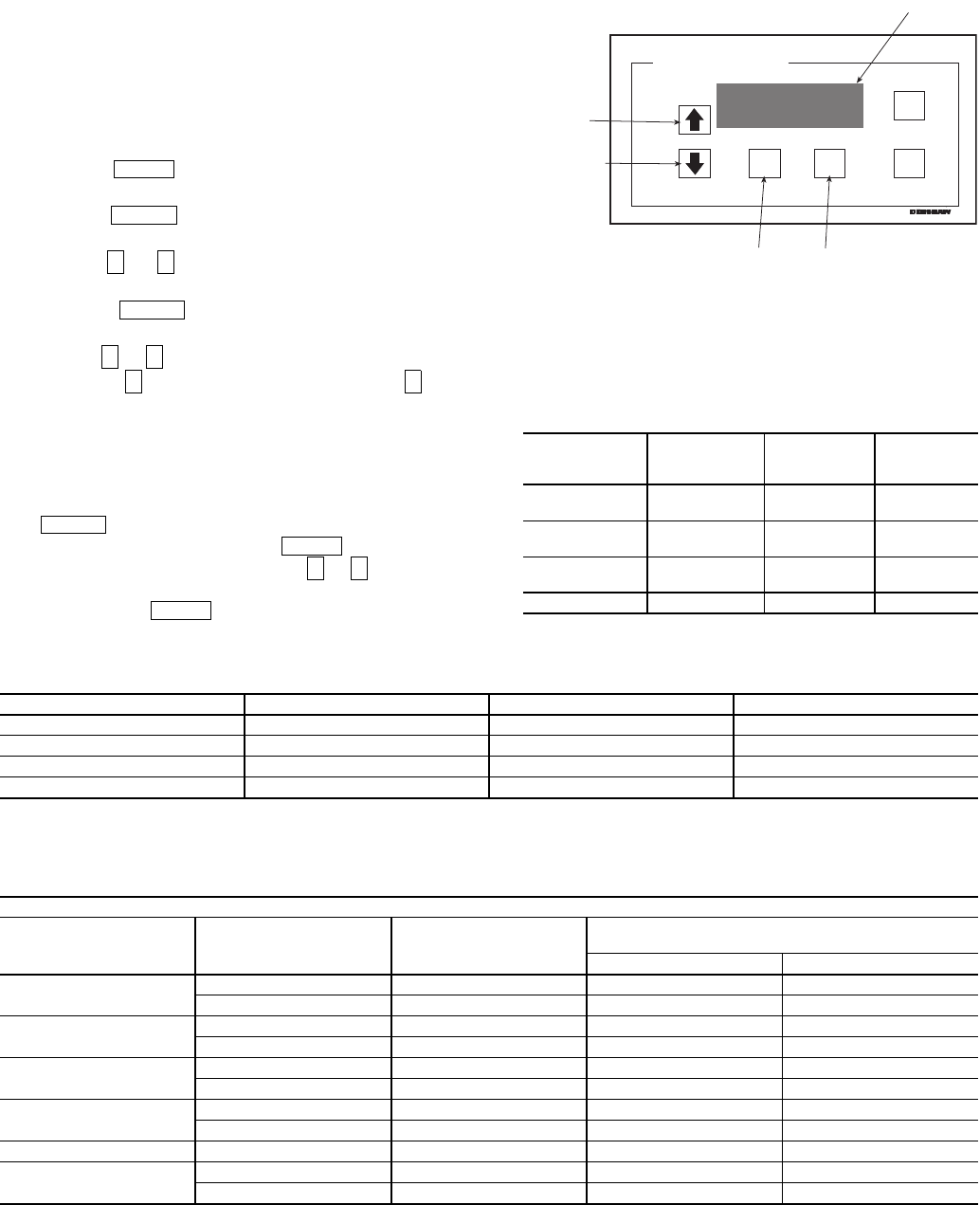
57
CHANGE THE BENSHAW INC., RediStart MICRO™
SOFTWARE CONFIGURATION IF NECESSARY — Ben-
shaw starter configurations are checked and modified from the
menus in the Benshaw Redistart MICRO Default Display. See
Fig. 32 and Table 6 for default display and menu items. To ac-
cess the menus to perform checks and modifications, the Ben-
shaw starter must be powered up and its self-test must have
been successfully completed. The self-test takes place automat-
ically after power-up. Current transformer ratio configurations
and hardware switch settings checks are performed in the
MENU1 display screen. See Table 7 for menu structure and
Table 8 for switch settings.
1. Press the softkey until the desired menu is se-
lected on the display.
2. Press the softkey to access the displayed menu
items (Table 6).
3. Use the or arrow keys to scroll between menu
items until the desired item is reached on the display.
4. Press the softkey to access the value to be
changed.
5. Use the or arrow keys to adjust the new displayed
value. The key increases the value while the key
decreases the value. Holding the arrow key will progres-
sively increase the rate of change. The value will stop
changing when either the factory set minimum or maxi-
mum value is reached. To make fine adjustments press
and release the arrow key.
6. When the correct value has been selected, press the
key to store the new configuration. At this
point, there are two options. The key will return
the display to the main display. The or arrow keys
will move the display to the next menu item. When fin-
ished press the key to return to the main display.
To view other settings and troubleshooting guide consult the
Benshaw RediStart MICRO instructional manual included in
the starter.
Table 6 — Benshaw RediStart
MICRO Menu Structure
Table 7 — Benshaw RediStart MICRO Menu Items*
*These values are not displayed in the ISM_CONFIG table.
Table 8 — Benshaw RediStart MICRO Current Transformer DIP Switch Settings
LEGEND
CT — Current Transformer
MENU
ENTER
↓ ↑
ENTER
↑ ↓
↑ ↓
ENTER MENU
↑ ↓
MENU
MENU 1
Starter Setup
MENU 2
Meter Setup
MENU 3
Event
Recorder
MENU 4
Dry Run
Mode
Initial Current
as % RLA
Meter #1
display
Events 1-99 Dry Run
Mode
Max. Cur
As% LRA
Meter #2
display
Ramp Time
(sec.)
CT Ratio: 1
DESCRIPTION RANGE UNITS DEFAULT
INITIAL CURRENT 50-300 % 125
MAX. CURR AS % LRA 30-70 % 55
RAMP TIME 5-30 SEC 15
CT RATIO 2640-5760 Enter Value from Table 8.
CURRENT TRANSFORMER CT1-CT3
Starter
Frame Size
(Amps)
Motor
RLA Range
(Amps)
CT
Ratio
MIcro Power Card (BIPCMIPWR-C4)
Overload Switch Settings
SW1-1 SW1-2
200 Amps 95- 135 Amps 3900:1 OFF OFF
136- 200 Amps 5760:1 OFF OFF
300 Amps 201- 231 Amps 2640:1 ON OFF
232- 300 Amps 3900:1 ON OFF
480 Amps 301- 340 Amps 3900:1 ON OFF
341- 480 Amps 5760:1 ON OFF
600 Amps 481- 580 Amps 2640:1 ON ON
581- 600 Amps 3900:1 ON ON
740 Amps 601- 740 Amps 3900:1 ON ON
1250 Amps 741- 855 Amps 3900:1 ON ON
856-1250 Amps 5760:1 ON ON
FAULT
RESET
MENU ENTER
DISPLAY
SCROLL UP
SCROLL DOWN
MENU
SELECTION
MENU ENTRY
DATA ENTRY
STOP I = OA
READY V = 461V
RediStart MICRO
Fig. 32 — Benshaw RediStart
MICRO Default Display
58
VERIFY VFD CONFIGURATION AND CHANGE
PARAMETERS IF NECESSARY
Using the Keypad — The keypad display is used to monitor,
view fault history and adjust the program of the VFD
microprocessor. It operates in two modes: Monitor mode and
Program mode:
Use the and keys to:
•Step through the drive parameter menus and error log
when the keypad/display is in Program mode.
•Increase or decrease a numeric value such as the refer-
ence or parameter value.
•Hold down these keys to increase the scroll speed.
Use the softkey to:
•Display a parameter or a selection value in Program
mode.
•Save a value.
•Move through each monitor display item when in Moni-
tor mode.
Monitor Mode (Default Mode) — Specific drive conditions
may be monitored on the keypad when in this mode. An LED
will be illuminated next to the description of what is displayed
on the keypad. Use the softkey to scroll through and
monitor the following selections:
•All LEDs on — Speed request from the CVC/ICVC
•Motor Speed
•Output Frequency
•Output Voltage
•Output Current
Program Mode — This mode displays and modifies the con-
figuration parameters of the VFD microprocessor. Particular
parameters, parameter numbers, and error log information can
be displayed when in Program mode.
Press the softkey until the PROGRAM LED is
illuminated to enter the Program mode.
Use the and keys to move through the menus
Press softkey to select the desired menu.
Press and keys to move through following parameters.
*Vector control is not used in this configuration.
Press softkey to select a parameter menu screen.
Press and keys to adjust the selected parameter.
Press the softkey until the PROGRAM LED
turns off to exit the program.
Accessing Password Protected Parameters — Although the
VFD controller has been preconfigured as the factory, the user
will need to be able to access the parameters to verify the job
specific parameters are correct, tune the controller or correct a
problem. The two passwords protecting the VFD configuration
are Parameter Set Display password and Program Disable
password. The Parameter Set Display password restricts view-
ing. P.nnn parameters above 007 and all H.nnn and R.nnn
screens. The password can be accessed at parameter P.006 and
will switch between enabled and disabled each time the pass-
word 107 is entered. The Program Disable password restricts
the changing of the drive parameter set. To enable or disable
changes select parameter P.051 and enter the password 26.
NOTE: Some of the parameters can be changed only when the
drive is stopped.
See the Initial Start-Up Checklist section for VFD Job Specific
Configuration table. For job specific parameters see inside of
the VFD enclosure door, next to the keypad. Refer to the VFD
Configuration table for the entire list of parameters.
VFD CHILLER FIELD SET UP AND VERIFICATION
Label Locations — Verify the following labels have been
installed properly and match the chiller requisition:
•Surge parameters — Located inside the control panel.
•Chiller identification nameplate — Located on the right
side of the control panel.
•VFD Parameter — Located to the right of the VFD con-
troller keypad on the VFD module.
•VFD Nameplate — Located on the right side of the VFD
as viewed from its front.
•Record all nameplate information on the Reliance Con-
figuration sheet.
Drive Protection and Other Incoming Wiring
1. Verify that the branch disconnects or other local discon-
nects are open and properly tagged out.
2. Verify that the branch circuit protection and AC input
wiring to the VFD are in accordance with NEC/CEC
(National Electrical Code/California Energy Commis-
sion) and all other local codes.
3. Verify that the fuses are per the field wiring diagram.
4. Verify that the incoming source does not exceed 85 kA.
5. Verify the power lugs in the VFD and branch protection
are properly secured. Inspect the ground cable and ensure
it is properly connected at the branch and to the ground
lug in the VFD.
6. Verify the conduit for the power wiring in securely con-
nected to the VFD flanged cover and runs continuously to
the branch protection.
7. Verify that the incoming and outgoing wires have been
properly connected inside of the reactor enclosure if a
separate line reactor has been added to the chiller.
8. Ensure the control and signal wires connected to the chill-
er controller or the VFD are in separate conduit.
IMPORTANT: The VFD controller has been factory con-
figured for use and communications to the Chiller Visual
Controller/International Chiller Visual Controller (CVC/
ICVC). Some parameters are specific to the chiller config-
uration and will need to be verified prior to operation.
Speed control and starting the drive have been disabled at
the VFD keypad. All command functions must be initiated
from the CVC/ICVC.
P.nnn —General Parameters
U.nnn —Vector Control Parameters*
H.nnn —Volts/Hertz Control Parameters
R.nnn —RMI Remote Monitor Interface
Parameters
E.nnn —Error Log (See fault codes)
Changing parameters may adversely affect chiller
operation.
↑ ↓
ENTER
ENTER
PROGRAM
↑ ↓
ENTER
↑ ↓
ENTER
↑ ↓
PROGRAM
It is the operator’s responsibility to distribute access to the
passwords. Carrier is not responsible for unauthorized
access violations within the operator’s organization. Failure
to observe this warning could result in bodily injury.
Restoring the default parameter P.050 will require all the
Carrier default parameters to be restored manually.
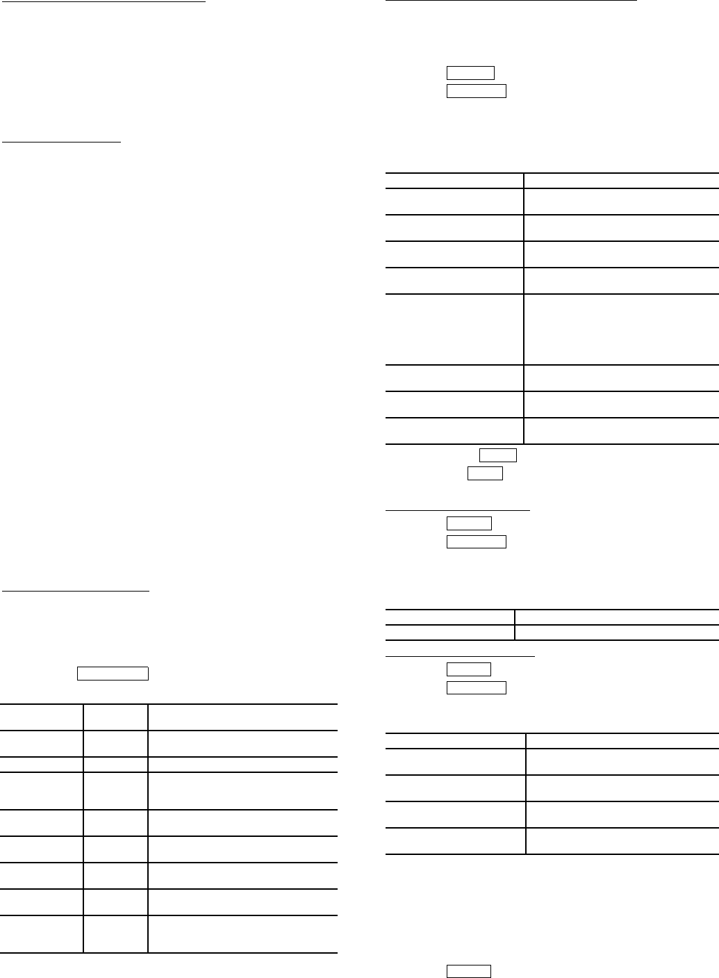
59
VFD Cooling System Leak Inspection
1. Check for leaks on the refrigerant cooling flange connec-
tions to the VFD enclosure.
2. Check for leaks on all tubing internal to the VFD enclo-
sure, the tubing flair connection to the VFD module and
the TXV valve.
3. Verify that the VFD refrigerant cooling system TXV
valve control bulb is securely inserted into the VFD drive
module heat sink.
Power Up Verification
1. Inspect control wiring inside the VFD and verify the in-
tegrity of the connections between the integrated starter
module (ISM) and the VFD module.
2. Close the control power switch in the VFD enclosure.
3. Close the oil pump power switch inside the VFD
enclosure.
4. Verify the VFD disconnect switch is in the open position.
5. Close and latch the doors of the VFD enclosure.
6. Apply power to the VFD enclosure. Remove lock outs
and close all disconnects.
7. Verify that the CVC/ICVC display powers up and goes to
the default screen.
8. Close the VFD disconnect switch.
9. Verify the following actions during the VFD start-up self
test:
• The display shows SELF and all LEDs are illumi-
nated for 5 to 6 seconds.
• The display reads a 0 after the diagnosis is
complete.
• If Err is displayed a fault has been detected.
Perform manual reset by establishing a reset
through the small hole under the VFD Keypad. If
this does not correct the fault contact your Carrier
representative.
• If AR with a counting down number is displayed
wait for the number to count to 0 and the display
should then revert to a 0. If the counter starts over
at 30 contact Carrier representative.
Configure VFD Parameters — The VFD controller must have
job specific parameters set as defined by the component name-
plates and labels. The parameters come preset by the factory,
but must be verified prior to start-up by accessing the PRO-
GRAM MODE of the VFD controller keypad. For information
on how to access the VFD keypad see page 58.
Press the softkey to access the parameter
screen to modify or view the following job specific parameters:.
Configure Chiller Visual Controller Parameter — The chiller
controller must have its job specific parameters set as defined
by the job sheet or installed nameplates. Below are the job spe-
cific parameters that must be set:
To access the ISM_CONF screen:
1. Press .
2. Press .
3. Enter the password 1111.
4. Select ISM (CONFIG STARTER DATA)
5. Scroll down and select the ISM_CONF DATA screen to
modify or view the ISM parameters:
6. Press to the softkey to save changes.
7. Press the softkey to and exit the ISM Configura-
tion Screen.
VFD Enable Configuration — To access the parameters:
1. Press .
2. Press .
3. Select EQUIPMENT SERVICE.
4. Scroll down and select SETUP2.
5. Verify the following parameters:
Configure Surge Parameters
1. Press .
2. Press .
3. Select EQUIPMENT SERVICE and OPTIONS to verify
the following:
VFD CONTROL VERFICATION (Non-Running) — In order
to verify and, if necessary, tune the speed control signal of the
chiller controller to the VFD (ISM terminal J8 1-2 labeled
4-20 mA OUT VFD) and the speed feedback signal from the
VFD to the chiller controller (ISM terminal J6 1-2 labeled
VFD HZ), follow the steps below.
Set TARGET VFD SPEED to 0%.
1. Press .
VFD
PARAMETER TITLE SETTING
P.004 Maximum
Speed
Line Frequency selected. Per
Compressor Nameplate.
P.006 Password 107
P.028 Speed
Display
Scaling
60 for 60 Hz selection and
50 for 50 Hz selection
H.000 Motor
Voltage
Compressor nameplate voltage.
H.001 Frequency Line Frequency selected. Per
Compressor Nameplate.
H.002 Motor
Amps
Compressor nameplate amps.
H.021 Line
Voltage
VFD nameplate voltage.
H.022 Over
Frequency
Limit
69 for 60 Hz selection and
57 for 50 Hz selection.
PROGRAM
DESCRIPTION SETTING
STARTER TYPE
(2 = SS/VFD)
2
MOTOR RATED
LINE VOLTAGE
VFD Nameplate Voltage.
MOTOR RATED
LOAD AMPS
VFD Nameplate Chiller Rated Load
Amps
MOTOR LOCKED
ROTOR TRIP
Compressor Nameplate
STARTER LRA RATING 600 for VFD
part #19XVR0414XXX
700 for VFD
part #19XVR0500XXX
900 for VFD
part #19XVR0643XXX
MOTOR CURRENT
CT RATIO:1
163
120 (414A)
3 GRND FAULT CT?
(1=NO)
NO
FREQUENCY-60HZ
(NO=50)
NO for 50 Hz selection
YES for 60 Hz selection
VFD OPTION ENABLED
VFD CURRENT LIMIT COMPRESSOR NAMEPLATE AMPS
DESCRIPTION SETTINGS
SURGE/HGBP
DELTA T1
Surge parameter label
SURGE/HGBP
DELTA P1
Surge parameter label
SURGE/HGBP
DELTA T2
Surge parameter label
SURGE/HGBP
DELTA P2
Surge parameter label
ENTER
SERVICE
SAVE
EXIT
MENU
SERVICE
MENU
SERVICE
MENU

60
2. Press .
3. Press .
4. Press .
5. Set TARGET VFD SPEED to 0%.
Verify that the ACTUAL VFD SPEED shown on the VFD dis-
play is within 0 to 1 Hz.
1. Press the softkey on the VFD keypad until all
LEDs on the left side of the keypad are illuminated.
NOTE: The value displayed is the frequency at which the
VFD is being commanded to operate.
2. Adjust VFD parameter P.009 (Input Offset) if outside the
tolerance.
To confirm that the speed signal from the CVC/ICVC
corresponds to the value displayed at the VFD:
3. Verify that the actual speed signal feedback to the chiller
controller is 0% by accessing the COMPRESS screen.
4. Verify ACTUAL SPEED VFD is 0%-1% on CVC/ICVC.
5. Adjust VFD parameter r.002 (Analog Output Offset) if
outside the tolerance.
Set VFD TARGET VFD SPEED to 100%.
1. Press .
2. Press .
3. Press .
4. Press .
5. Set TARGET VFD SPEED to 100%.
Verify that the ACTUAL VFD SPEED shown on the VFD dis-
play corresponds to the 50 Hz or 60 Hz setting.
1. Check the ACTUAL VFD SPEED configuration (50 Hz
or 60 Hz) on the ISM_CONF screen.
2. Confirm that the VFD displays the configured line fre-
quency within ± 1 Hz.
3. Adjust parameter P.010 (Input Gain) if outside the
tolerance.
4. Release the TARGET VFD SPEED so that it can operate
in automatic mode. (Refer to Override Operations section
on page 16.)
VFD CONTROL VERIFICATION (Running)
Preparation
1. Disconnect power to the VFD. Verify that the branch dis-
connects or other local disconnects are open and properly
tagged out.
2. Connect a voltmeter and ampmeter to the line side of the
VFD. Locate meters safely away from the power cables.
3. Reconnect power to the VFD.
4. Measure the voltage on the line side of the drive.
5. Verify it is within 10% of the chiller nameplate voltage.
6. Set up the CVC/ICVC temperature controller per the re-
quirements of the job.
7. Start the chiller and verify the rotation of the compressor
just as it starts.
8. Allow the chiller to load up. Verify that the chiller loads
up smoothly.
NOTE: One or two surges may be counted during the first
minute of operation.
Verify That Actual VFD Speed is 100% (±2%)
1. Set the VFD speed to 100%.
2. Verify that the ACTUAL VFD SPEED is 100% (± 2%).
3. If outside the tolerance, adjust r.003 (Output Analog
Gain).
4. Leave running for the next test.
ISM Current Calibration Check
1. With the target VFD speed at 100%, load the chiller so
that the CVC/ICVC default display shows 75% to 100%
under the display title AMPS %. A higher load is
preferred.
2. Measure the incoming current with a separate amp meter.
3. Calculate the line side error ratio using the following
equation:
4. If the Line Side Error Ratio is greater than ± 0.02 adjust
the CVC/ICVC reading by adjusting the ISM CT
ratio.
5. Shut down the chiller.
Change CT Ratio
1. New CT Ratio = Present CT Ratio multiplied by (1+ Line
Side Error Ratio).
To access the ISM_CONF screen:
2. Press .
3. Press .
4. Enter the password 1111.
5. Select ISM (STARTER) CONFIG DATA.
6. Enter password 4444.
7. Select ISM_CONF.
8. Change present CT ratio to new ratio using calculation
above.
9. Press to the softkey to save changes.
10. Press the softkey to exit the ISM_CONF screen.
11. Repeat ISM Current Calibration Check.
VFD Current Control Calibration Check
1. With the target VFD speed at 100%, load the chiller so
that the CVC/ICVC default display shows 75% to 100%
under the display title AMPS %. A higher load is
preferred.
2. Access the current on the keypad of the VFD. Determine
the Load Side Current Ratio, using the equation below.
Load Side Current Ratio =
Next, access the VFD Load Factor on the Capacity Con-
trol screen. Calculate the Load Side Error Ratio using the
equation below:
3. If the load side error ratio is greater than ± 0.02, adjust the
VFD load factor by changing the VFD current limit on
the Setup 2 screen.
a. The new VFD current limit = old VFD current
limit multiplied by (1+ Load Side Error Ratio).
b. Recheck the VFD Current Control Calibration.
c. Release the Speed Control by accessing the TAR-
GET VFD SPEED control.
Press .
Press .
Press .
(Refer to Override Operations section on page 16.)
STATUS
COMPRESS
SELECT
ENTER
MENU
STATUS
COMPRESS
SELECT
Amp Meter current – Ave. ISM current
Amp Meter current
VFD Actual Load Amps
Motor Nameplate Amps
Load Side
Error Ratio =VFD Load Factor – Load Side Current Ratio
Load Side Current Ratio
ENTER
SERVICE
SAVE
EXIT
MENU
STATUS
COMPRESS
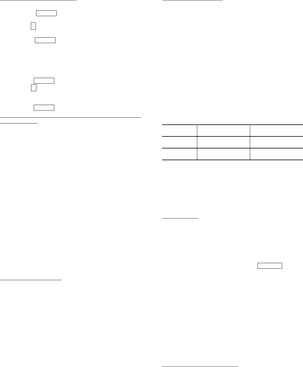
61
Protecting the VFD Configuration
1. Select parameter P.051 from the VFD keypad.
2. Press the softkey to access the parameter. A
zero will be displayed.
3. Use the arrow key to increment the value to 26. This is
the password number.
4. Press the softkey to save the value. P.051 will
by displayed.
NOTE: Parameter programming is disabled when the
PASSWORD LED is on and enabled when the PASS-
WORD LED is off.
5. Select parameter P.006 from the VFD Keypad.
6. Press the softkey to access the parameter.
7. Use the arrow key to increment the value to 107. This
is the password number to restrict displaying the remain-
ing P, and all of the H and r parameters.
8. Press the softkey to save the value.
Modify Minimum and Maximum Load Points (∆T1/P1; ∆T2/
P2) If Necessary — These pairs of chiller load points, located
on the OPTIONS screen, determine when to limit guide vane
travel or open the hot gas bypass valve when surge prevention
is needed. These points should be set based on individual
chiller operating conditions.
A label that lists the configuration values of the controls is
located on the inside of the unit’s control panel. These values
are based upon the original selection of the chiller. Jobsite con-
ditions may require a slight modification to these parameters.
If after configuring a value for these points, surge preven-
tion is operating too soon or too late for conditions, these pa-
rameters should be changed by the operator.
An example of such a configuration is shown below.
Refrigerant: HCFC-134a
Estimated Minimum Load Conditions:
44 F (6.7 C) LCW
45.5 F (7.5 C) ECW
43 F (6.1 C) Suction Temperature
70 F (21.1 C) Condensing Temperature
Estimated Maximum Load Conditions:
44 F (6.7 C) LCW
54 F (12.2 C) ECW
42 F (5.6 C) Suction Temperature
98 F (36.7 C) Condensing Temperature
Calculate Maximum Load — To calculate the maximum load
points, use the design load condition data. If the chiller full load
cooler temperature difference is more than 15 F (8.3 C), esti-
mate the refrigerant suction and condensing temperatures at
this difference. Use the proper saturated pressure and tempera-
ture for the particular refrigerant used.
Suction Temperature:
42 F (5.6 C) = 37 psig (255 kPa) saturated
refrigerant pressure (HFC-134a)
Condensing Temperature:
98 F (36.7 C) = 120 psig (1827 kPa) saturated
refrigerant pressure (HFC-134a)
Maximum Load ∆T2:
54 – 44 = 10º F (12.2 – 6.7 = 5.5º C)
Maximum Load ∆P2:
120 – 37 = 83 psid (827 – 255 = 572 kPad)
To avoid unnecessary surge prevention, add about 10 psid
(70 kPad) to ∆P2 from these conditions:
∆T2 = 10º F (5.5º C)
∆P2 = 93 psid (642 kPad)
Calculate Minimum Load — To calculate the minimum load
conditions, estimate the temperature difference the cooler will
have at 10% load, then estimate what the suction and condens-
ing temperatures will be at this point. Use the proper saturated
pressure and temperature for the particular refrigerant used.
Suction Temperature:
43 F (6.1 C) = 38 psig (262 kPa) saturated
refrigerant pressure (HFC-134a)
Condensing Temperature:
70 F (21.1 C) = 71 psig (490 kPa) saturated
refrigerant pressure (HFC-134a)
Minimum Load ∆T1 (at 20% Load): 2 F (1.1 C)
Minimum Load ∆P1:
71 – 38 = 33 psid (490 – 262 = 228 kPad)
Again, to avoid unnecessary surge prevention, add 20 psid
(140 kPad) at ∆P1 from these conditions:
∆T1 = 2 F (1.1 C)
∆P1 = 53 psid (368 kPad)
If surge prevention occurs too soon or too late:
The differential pressure (∆P) and temperature (∆T) can be
monitored during chiller operation by viewing ACTIVE
DELTA P and ACTIVE DELTA T (HEAT_EX screen). Com-
paring SURGE/HGBP DELTA T to ACTIVE DELTA T will de-
termine when the SURGE PREVENTION function will occur.
The smaller the difference between the SURGE/HGBP DELTA
T and the ACTIVE DELTA T values, the closer to surge
prevention.
Units with VFD — On units with VFD further adjustments can
be made if response to surge prevention or protection is not
functioning as desired. VFD GAIN and VFD INCREASE STEP
can be adjusted to allow for more aggressive changes in speed
when surge prevention or protection is active.
CONFIGURE DIFFUSER CONTROL IF NECES-
SARY — If the compressor is equipped with a variable dif-
fuser, (size 5 compressor) access the SETUP2 screen. Scroll to
DIFFUSER CONTROL and press the softkey.
Compare the diffuser and guide vane values (GUIDE VANE
25% LOAD PT, GUIDE VANE 50% LOAD PT, GUIDE VANE
75% LOAD PT, DIFFUSER 25% LOAD POINT, DIFFUSER
50% LOAD POINT, DIFFUSER 75% LOAD POINT) to the
values located on the label inside the control panel. See
Fig. 12.
Compressors with variable diffuser control have actuators
tested and stamped with the milliamp (mA) value that results in
100% actuator rotation. This value is configured on the
SETUP2 screen. It is labeled DIFFUSER FULL SPAN mA.
MODIFY EQUIPMENT CONFIGURATION IF NECES-
SARY — The EQUIPMENT SERVICE table has screens to
select, view, or modify parameters. Carrier’s certified drawings
have the configuration values required for the jobsite. Modify
these values only if requested.
SERVICE Screen Modifications — Change the values on
these screens according to specific job data. See the certified
drawings for the correct values. Modifications can include:
•chilled water reset
•entering chilled water control (Enable/Disable)
•4 to 20 mA demand limit
•auto restart option (Enable/Disable)
•remote contact option (Enable/Disable)
ENTER
↑
ENTER
ENTER
↑
ENTER
LOAD SURGE PREVENTION
OCCURS TOO SOON
SURGE PREVENTION
OCCURS TOO LATE
At low loads
(<50%)
Increase P1 by
2 psid (14 kPad)
Decrease P1 by
2 psid (14 kPad)
At high loads
(>50%)
Increase P2 by
2 psid (14 kPad)
Decrease P2 by
2 psid (14 kPad)
ENABLE

62
Owner-Modified CCN Tables — The following EQUIP-
MENT CONFIGURATION screens are described for refer-
ence only.
OCCDEFCS — The OCCDEFCS screen contains the Local
and CCN time schedules, which can be modified here or on the
SCHEDULE screen as described previously.
HOLIDAYS — From the HOLIDAYS screen, the days of the
year that holidays are in effect can be configured. See the holi-
day paragraphs in the Controls section for more details.
BRODEF — The BRODEF screen defines the start and end of
daylight savings time. Enter the dates for the start and end of
daylight savings if required for your location. BRODEF also
activates the Broadcast function which enables the holiday
periods that are defined on the CVC/ICVC to take effect.
Other Tables — The CONSUME, NET_OPT, and RUN-
TIME screens contain parameters used with a CCN system.
See the applicable CCN manual for more information on these
screens. These tables can only be defined from a CCN Build-
ing Supervisor.
Perform a Control Test — Check the safety controls
status by performing an automated control test. Access the
CONTROL TEST table and select a test to be performed func-
tion (Table 9).
The Automated Control Test checks all outputs and inputs
for function. In order to successfully proceed with the controls
test, the compressor should be off, no alarms showing, and volt-
age should be within ±10% of rating plate value. The compres-
sor can be put in OFF mode by pressing the STOP push-button
on the CVC/ICVC. Each test asks the operator to confirm the
operation is occurring and whether or not to continue. If an er-
ror occurs, the operator can try to address the problem as the
test is being done or note the problem and proceed to the next
test.
NOTE: Enter guide vane calibration to calibrate guide
input on CCM (Plug J4 upper terminal 9 and 10).
NOTE: If during the control test the guide vanes do not open,
verify the low pressure alarm is not active. (An active low
pressure alarm causes the guide vanes to close.)
NOTE: The oil pump test will not energize the oil pump if
cooler pressure is below –5 psig (–35 kPa).
When the control test is finished or the softkey is
pressed, the test stops, and the CONTROL TEST menu dis-
plays. If a specific automated test procedure is not completed,
access the particular control test to test the function when ready.
The CONTROL TEST menu is described in the table below.
*Diffuser tests function only on size 4 and 5 compressor with diffuser control
enabled.
NOTE: During any of the tests, an out-of-range reading will have an asterisk
(*) next to the reading and a message will be displayed if you have diffuser
control enabled.
COOLER CONDENSER PRESSURE TRANSDUCER
AND WATERSIDE FLOW DEVICE CALIBRATION
(Optional with ICVC inputs available) — Calibration can be
checked by comparing the pressure readings from the
transducer to an accurate refrigeration gage reading. These
readings can be viewed or calibrated from the HEAT_EX
screen on the CVC/ICVC. The transducer can be checked and
calibrated at 2 pressure points. These calibration points are
0 psig (0 kPa) and between 25 and 250 psig (173 and
1724 kPa). To calibrate these transducers:
1. Shut down the compressor, cooler, and condenser pumps.
NOTE: There should be no flow through the heat
exchangers.
2. Disconnect the transducer in question from its Schrader
fitting for cooler or condenser transducer calibration. For
oil pressure or flow device calibration keep transducer in
place.
NOTE: If the cooler or condenser vessels are at 0 psig
(0 kPa) or are open to atmospheric pressure, the transduc-
ers can be calibrated for zero without removing the trans-
ducer from the vessel.
3. Access the HEAT_EX screen and view the particular
transducer reading (the EVAPORATOR PRESSURE or
CONDENSER PRESSURE parameter on the HEAT_EX
screen). To calibrate oil pressure or waterside flow de-
vice, view the particular reading (CHILLED WATER
DELTA P and CONDENSER WATER DELTA P on the
HEAT_EX screen and OIL PUMP DELTA P on the
COMPRESS screen). It should read 0 psi (0 kPa). If the
reading is not 0 psi (0 kPa), but within ±5 psi (35 kPa),
the value may be set to zero by pressing the
softkey while the appropriate transducer parameter is
highlighted on the CVC/ICVC screen. Then press the
softkey. The value will now go to zero. No high
end calibration is necessary for OIL PUMP DELTA P or
flow devices.
If the transducer value is not within the calibration range,
the transducer returns to the original reading. If the pres-
sure is within the allowed range (noted above), check the
voltage ratio of the transducer. To obtain the voltage ratio,
divide the voltage (dc) input from the transducer by the
supply voltage signal (displayed in CONTROL TEST
menu in the CCM PRESSURE TRANSDUCERS
screen) or measure across the positive (+ red) and nega-
tive (– black) leads of the transducer. For example, the
condenser transducer voltage input is measured at CCM
terminals J2-4 and J2-5. The voltage ratio must be be-
tween 0.80 and 0.11 for the software to allow calibration.
Rotate the waterside flow pressure device from the inlet
nozzle to the outlet nozzle and repeat this step. If rotating
the waterside flow device does not allow calibration then
pressurize the transducer until the ratio is within range.
Then attempt calibration again.
4. A high pressure point can also be calibrated between 25
and 250 psig (172.4 and 1723.7 kPa) by attaching a regu-
lated 250 psig (1724 kPa) pressure (usually from a nitro-
gen cylinder). The high pressure point can be calibrated
by accessing the appropriate transducer parameter on the
HEAT_EX screen, highlighting the parameter, pressing
the softkey, and then using the
or softkeys to adjust the value to the exact
pressure on the refrigerant gage. Press the soft-
key to finish the calibration. Pressures at high altitude lo-
cations must be compensated for, so the chiller tempera-
ture/pressure relationship is correct.
The PIC II does not allow calibration if the transducer is too
far out of calibration. In this case, a new transducer must be
installed and recalibrated.
CCM Temperature Thermistors Check of all thermistors.
CCM Pressure Transducers Check of all transducers.
Pump
Checks operation of pump outputs;
pumps are activated. Also tests associ-
ated inputs such as flow or pressure.
Discrete outputs Activation of all on/off outputs individu-
ally.
Guide Vane Check of the guide vane operation.
Diffuser Actuator* Check of the diffuser actuator.
Pumpdown/Lockout
Pumpdown prevents the low refrigerant
alarm during evacuation so refrigerant
can be removed form the unit. Also locks
the compressor off and starts the water
pumps.
Terminate Lockout To charge refrigerant and enable the
chiller to run after pumpdown lockout.
Guide Vane Calibration Calibrates guide vane input on CCM.
EXIT
SELECT
ENTER
SELECT INCREASE
DECREASE ENTER
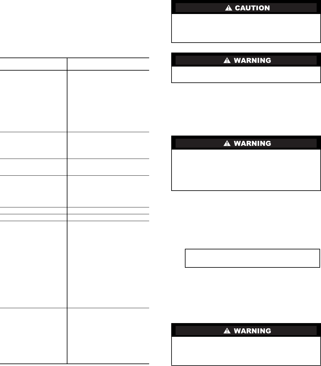
63
Check Optional Pumpout System Controls
and Compressor — Controls include an on/off switch,
a 3-amp fuse, the compressor overloads, an internal thermostat,
a compressor contactor, and a refrigerant high pressure cutout.
The high pressure cutout is factory set to open at 161 psig
(1110 kPa) and reset at 130 psig (896 kPa). Ensure the water-
cooled condenser has been connected. Loosen the compressor
holddown bolts to allow free spring travel. Open the compres-
sor suction and discharge the service valves. Ensure oil is visi-
ble in the compressor sight glass. Add oil if necessary.
See the Pumpout and Refrigerant Transfer Procedures and
Optional Pumpout System Maintenance sections, pages 67 and
75, for details on the transfer of refrigerant, oil specifications,
etc.
Table 9 — Control Test Menu Functions
High Altitude Locations — Because the chiller is ini-
tially calibrated at sea level, it is necessary to recalibrate the
pressure transducers if the chiller has been moved to a high alti-
tude location. See the calibration procedure in the Trouble-
shooting Guide section.
Charge Refrigerant into Chiller
The standard 19XR chiller is shipped with the refrigerant
already charged in the vessels. However, the 19XR may be or-
dered with a nitrogen holding charge of 15 psig (103 kPa).
Evacuate the nitrogen from the entire chiller, and charge the
chiller from refrigerant cylinders.
CHILLER EQUALIZATION WITHOUT A PUMPOUT
UNIT
To equalize the pressure differential on a refrigerant isolated
19XR chiller, use the terminate lockout function of the CON-
TROL TEST on the SERVICE menu. This helps to turn on
pumps and advises the operator on proper procedures.
The following steps describe how to equalize refrigerant
pressure in an isolated 19XR chiller without a pumpout unit.
1. Access terminate lockout function on the CONTROL
TEST screen.
2.
3. Slowly open the refrigerant cooling isolation valve. The
chiller cooler and condenser pressures will gradually
equalize. This process takes approximately 15 minutes.
4. Once the pressures have equalized, the cooler isolation
valve, the condenser isolation valve, and the hot gas isola-
tion valve may now be opened. Refer to Fig. 29 and 30,
for the location of the valves.
TESTS TO BE
PERFORMED DEVICES TESTED
1. CCM Thermistors Entering Chilled Water
Evaporator Refrigerant Tempera-
ture (ICVC only)
Leaving Chilled Water
Entering Condenser Water
Leaving Condenser Water
Remote Reset Sensor
Comp Discharge Temp
Oil Sump Temp
Comp Motor Winding Temp
Space Temperature 1
Space Temperature 2
2. CCM Pressure
Transducers
Evaporator Pressure
Condenser Pressure
Oil Pump Delta P
Condenser Water Delta P
Transducer Voltage Ref
3. Pumps Chilled Water — Confirm pressure
Condenser Water — Confirm
Delta P
4. Discrete Outputs Oil Heater Relay
Hot Gas Bypass Relay
Tower Fan Relay Low
Tower Fan Relay High
Alarm Relay
Shunt Trip Relay
5. Guide Vane Actuator Open/Close
6. Diffuser Actuator Open/Close
7. Pumpdown Lockout When using pumpdown/lockout,
observe freeze up precautions when
removing charge:
Instructs operator which valves to
close and when.
Starts chilled water and condenser
water pumps and confirms flows.
Monitors
Evaporator pressure
Condenser pressure
Evaporator temperature during
pumpout procedures
Turns pumps off after pumpdown.
Locks out compressor.
8 Terminate Lockout Starts pumps and monitors flows.
Instructs operator which valves to
open and when.
Monitors
Evaporator pressure
Condenser pressure
Evaporator temperature during
charging process
Terminates compressor lockout.
The transfer, addition, or removal of refrigerant in spring
isolated chillers may place severe stress on external piping
if springs have not been blocked in both up and down
directions.
Always operate the condenser and chilled water pumps
during charging operations to prevent freeze-ups.
When equalizing refrigerant pressure on the 19XR chiller
after service work or during the initial chiller start-up, do
not use the discharge isolation valve to equalize. Either the
motor cooling isolation valve or the charging hose (con-
nected between the pumpout valves on top of the cooler
and condenser) should be used as the equalization valve.
Whenever turning the discharge isolation valve, be sure to
reattach the valve locking device. This prevents the valve
from opening or closing during service work or during
chiller operation.
IMPORTANT: Turn on the chilled water and con-
denser water pumps to prevent freezing.
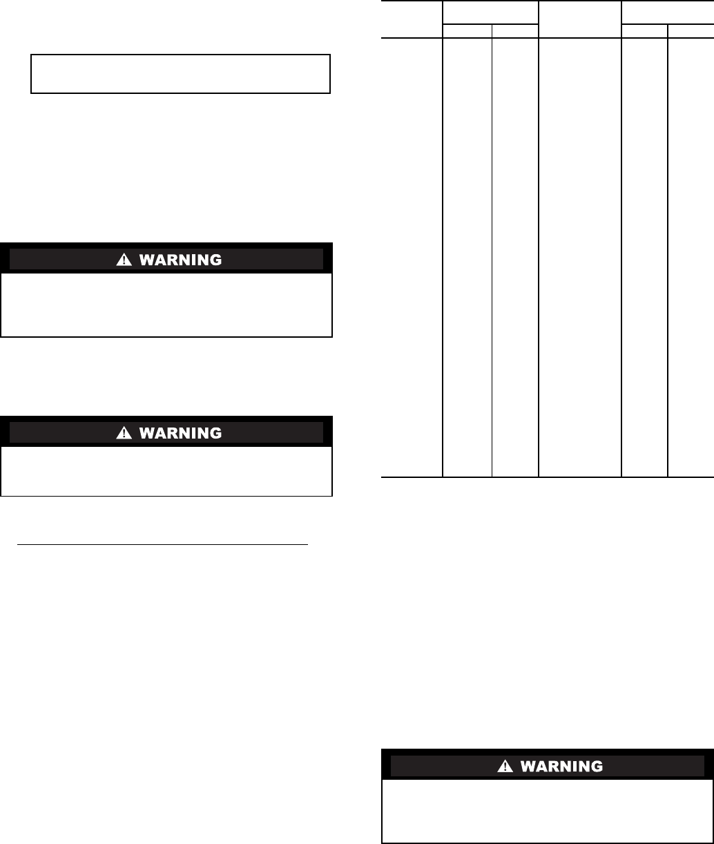
64
CHILLER EQUALIZATION WITH PUMPOUT UNIT —
The following steps describe how to equalize refrigerant pres-
sure on an isolated 19XR chiller using the pumpout unit.
1. Access the terminate lockout function on the CONTROL
TEST screen.
2.
3. Open valve 4 on the pumpout unit and open valves 1a and
1b on the chiller cooler and condenser, Fig. 29 and 30.
Slowly open valve 2 on the pumpout unit to equalize the
pressure. This process takes approximately 15 minutes.
4. Once the pressures have equalized, the discharge isola-
tion valve, cooler isolation valve, optional hot gas bypass
isolation valve, and the refrigerant isolation valve can be
opened. Close valves 1a and 1b, and all pumpout unit
valves.
The full refrigerant charge on the 19XR will vary with chill-
er components and design conditions, as indicated on the job
data specifications. An approximate charge may be determined
by adding the condenser charge to the cooler charge as listed in
Table 10.
Use the CONTROL TEST terminate lockout function to
monitor conditions and start the pumps.
If the chiller has been shipped with a holding charge, the
refrigerant is added through the pumpout charging connection
(Fig. 29 and 30, valve 1b). First evacuate the nitrogen holding
charge from the chiller vessels. Charge the refrigerant as a gas
until the system pressure exceeds 35 psig (141 kPa) for
HFC-134a. After the chiller is beyond this pressure the refrig-
erant should be charged as a liquid until all the recommended
refrigerant charge has been added. The charging valve (Fig. 29
and 30, valve 7) can be used to charge liquid to the cooler if the
cooler isolation valve (11) is present and is closed. Do not
charge liquid through the linear float to the condenser.
TRIMMING REFRIGERANT CHARGE — The 19XR is
shipped with the correct charge for the design duty of the chill-
er. Trimming the charge can best be accomplished when the
design load is available. To trim the charge, check the tempera-
ture difference between the leaving chilled water temperature
and cooler refrigerant temperature at full load design condi-
tions. If necessary, add or remove refrigerant to bring the
temperature difference to design conditions or minimum
differential.
Table 10 lists the 19XR chiller refrigerant charges for each
cooler and condenser code. Total refrigerant charge is the sum
of the cooler and condenser charge.
Table 10 — Refrigerant (HFC-134a) Charge
INITIAL START-UP
Preparation — Before starting the chiller, verify:
1. Power is on to the main starter, oil pump relay, tower fan
starter, oil heater relay, and the chiller control panel.
2. Cooling tower water is at proper level and at-or-below
design entering temperature.
3. Chiller is charged with refrigerant and all refrigerant and
oil valves are in their proper operating positions.
4. Oil is at the proper level in the reservoir sight glasses.
5. Oil reservoir temperature is above 140 F (60 C) or above
refrigerant temperature plus 50° F (28° C).
6. Valves in the evaporator and condenser water circuits are
open.
NOTE: If the pumps are not automatic, ensure water is
circulating properly.
7. Access the CONTROL TEST screen. Scroll down on the
TERMINATE LOCKOUT option. Press the SELECT (to
enable the chiller to start) and answer YES to reset unit to
operating mode. The chiller is locked out at the factory in
order to prevent accidental start-up.
Whenever turning the discharge isolation valve, be sure to
reattach the valve locking device. This prevents the valve
from opening or closing during service work or during
chiller operation.
Always operate the condenser and chilled water pumps
whenever charging, transferring, or removing refrigerant
from the chiller.
IMPORTANT: Turn on the chilled water and con-
denser water pumps to prevent freezing.
COOLER
CODE
REFRIGERANT
CHARGE CONDENSER
CODE
REFRIGERANT
CHARGE
lb kg lb kg
10 290 132 10 200 91
11 310 141 11 200 91
12 330 150 12 200 91
15 320 145 15 250 113
16 340 154 16 250 113
17 370 168 17 250 113
20 345 157 20 225 102
21 385 175 21 225 102
22 435 197 22 225 102
30 350 159 30 260 118
31 420 190 31 260 118
32 490 222 32 260 118
35 400 181 35 310 141
36 480 218 36 310 141
37 550 250 37 310 141
40 560 254 40 280 127
41 630 286 41 280 127
42 690 313 42 280 127
45 640 290 45 330 150
46 720 327 46 330 150
47 790 358 47 330 150
50 750 340 50 400 181
51 840 381 51 400 181
52 900 408 52 400 181
55 870 395 55 490 222
56 940 426 56 490 222
57 980 445 57 490 222
60 940 426 60 420 190
61 980 445 61 420 190
62 1020 463 62 420 190
65 1020 463 65 510 231
66 1060 481 66 510 231
67 1090 494 67 510 231
70 1220 553 70 780 354
71 1340 608 71 780 354
72 1440 653 72 780 354
75 1365 619 75 925 420
76 1505 683 76 925 420
77 1625 737 77 925 420
80 1500 680 80 720 327
81 1620 735 81 720 327
82 1730 785 82 720 327
85 1690 766 85 860 390
86 1820 825 86 860 390
87 1940 880 87 860 390
Do not permit water or brine that is warmer than 110 F
(43 C) to flow through the cooler or condenser. Refrigerant
overpressure may discharge through the relief valves and
result in the loss of refrigerant charge.
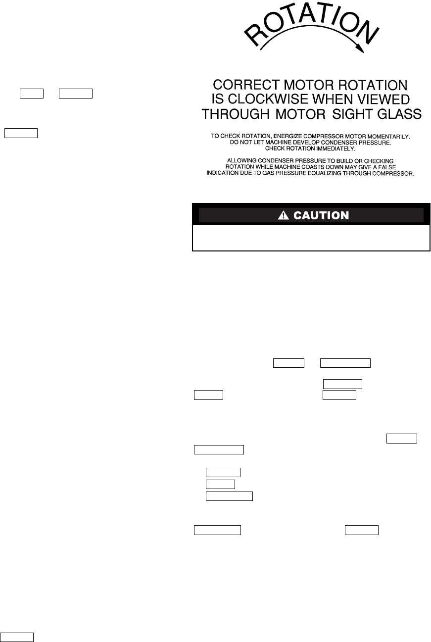
65
Dry Run to Test Start-Up Sequence
For electro-mechanical starters.
1. Disengage the main motor disconnect (CB1) on the start-
er front panel. This should only disconnect the motor
power. Power to the controls, oil pump, and starter con-
trol circuit should still be energized.
2. Observe the default screen on the CVC/ICVC: the status
message in the upper left-hand corner reads, “Manually
Stopped,” Press the or softkey to start.
If the chiller controls do not go into a start mode (“Unoc-
cupied Mode” is displayed) go to the SCHEDULE screen
and override the schedule or change the occupied
time. Press the softkey to begin the start-up
sequences.
3. View the STARTUP display screen and verify the chilled
water and condenser water pumps have energized.
4. Verify the oil pump has started and is pressurizing the
lubrication system. After the oil pump has run about
11 seconds, the starter energizes (COMPRESSOR START
CONTACT is closed) and goes through its start-up
sequence.
5. Check the main contactor (1M) for proper operation.
6. The PIC II eventually shows an alarm for motors amps
not sensed. Reset this alarm and continue with the initial
start-up.
For Benshaw Inc. solid-state starters:
1. Close the main motor disconnect (CB1). Voltage will be
applied to the compressor motor but the SCRs will not
fire (compressor motor will not rotate). Enter MENU 4 in
the Benshaw RediStart MICRO™ Menu structure at the
Benshaw display (see Input Service Configurations,
Change The Benshaw RediStart MICRO Software Con-
figuration page 57). Select Dry Run Mode and scroll to
YES.
2. Follow steps 2 through 4 for the electro-mechanical start-
ers. When the Ramp Time is set for less than 10 seconds
COMPRESSOR RUN CONTACT will close.
3. The PIC II eventually shows an alarm for motors amps
not sensed. Reset this alarm and enter MENU 4 in the
Benshaw display. Select Dry Run Mode and scroll to NO.
Continue with the initial start-up.
Check Motor Rotation
1. Engage the oil pump circuit breaker (CB3) located inside
the right hand side of the starter panel.
2. Then engage the control power circuit breaker (CB2) lo-
cated in the same section of the starter cabinet.
3. Finally close the main motor disconnect (CB1) on the
front of the starter panel.
4. The ISM mounted in the electro-mechanical starters
checks for proper phase rotation as soon as power is
applied to the starter and the PIC II controls power up.
Solid-state starters have phase protection and do not per-
mit a start if the phase rotation is not correct.
5. An alarm message will appear on the CVC/ICVC if the
phase rotation is incorrect. If this occurs reverse any 2 of
the 3 incoming power leads to the starter and reapply
power. The motor is now ready for a rotation check.
6. After the default screen status message states ‘Ready to
Start’ press the softkey. The PIC II control per-
forms start-up checks.
7. When the starter is energized and the motor begins to
turn, check for clockwise motor rotation (Fig. 33).
Check Oil Pressure and Compressor Stop
1. When the motor is at full speed, note the differential oil
pressure reading on the CVC/ICVC default screen. It
should be between 18 and 30 psid (124 to 206 kPad).
2. Press the Stop button and listen for any unusual sounds
from the compressor as it coasts to a stop.
To Prevent Accidental Start-Up — A chiller STOP
override setting may be entered to prevent accidental start-up
during service or whenever necessary. Access the MAINSTAT
screen and using the or softkeys, high-
light the CHILLER START/STOP parameter. Override the cur-
rent START value by pressing the softkey. Press the
softkey followed by the softkey. The word
SUPVSR! displays on the CVC/ICVC indicating the override
is in place.
To restart the chiller the STOP override setting must be re-
moved. Access the MAINSTAT screen and using or
softkeys highlight CHILLER START/STOP. The
3 softkeys that appear represent 3 choices:
• — forces the chiller ON
• — forces the chiller OFF
• — puts the chiller under remote or schedule
control.
To return the chiller to normal control, press the
softkey followed by the softkey. For
more information, see Local Start-Up, page 46.
The default CVC/ICVC screen message line indicates
which command is in effect.
Check Chiller Operating Condition — Check to
be sure that chiller temperatures, pressures, water flows, and
oil and refrigerant levels indicate the system is functioning
properly.
Instruct the Customer Operator — Ensure the op-
erator(s) understand all operating and maintenance procedures.
Point out the various chiller parts and explain their function as
part of the complete system.
COOLER-CONDENSER — Float chamber, relief valves, re-
frigerant charging valve, temperature sensor locations, pressure
transducer locations, Schrader fittings, waterboxes and tubes,
and vents and drains.
CCN LOCAL
LOCAL
LOCAL
Do not check motor rotation during coastdown. Rotation
may have reversed during equalization of vessel pressures.
NEXT PREVIOUS
SELECT
STOP ENTER
NEXT
PREVIOUS
START
STOP
RELEASE
RELEASE ENTER
Fig. 33 — Correct Motor Rotation

66
OPTIONAL PUMPOUT STORAGE TANK AND PUMP-
OUT SYSTEM — Transfer valves and pumpout system, refrig-
erant charging and pumpdown procedure, and relief devices.
MOTOR COMPRESSOR ASSEMBLY — Guide vane actu-
ator, transmission, motor cooling system, oil cooling system,
temperature and pressure sensors, oil sight glasses, integral oil
pump, isolatable oil filter, extra oil and motor temperature sen-
sors, synthetic oil, and compressor serviceability.
MOTOR COMPRESSOR LUBRICATION SYSTEM —
Oil pump, cooler filter, oil heater, oil charge and specification,
operating and shutdown oil level, temperature and pressure,
and oil charging connections.
CONTROL SYSTEM — CCN and LOCAL start, reset,
menu, softkey functions, CVC/ICVC operation, occupancy
schedule, set points, safety controls, and auxiliary and optional
controls.
AUXILIARY EQUIPMENT — Starters and disconnects,
separate electrical sources, pumps, and cooling tower.
DESCRIBE CHILLER CYCLES — Refrigerant, motor
cooling, lubrication, and oil reclaim.
REVIEW MAINTENANCE — Scheduled, routine, and ex-
tended shutdowns, importance of a log sheet, importance of
water treatment and tube cleaning, and importance of maintain-
ing a leak-free chiller.
SAFETY DEVICES AND PROCEDURES — Electrical dis-
connects, relief device inspection, and handling refrigerant.
CHECK OPERATOR KNOWLEDGE — Start, stop, and
shutdown procedures, safety and operating controls, refrigerant
and oil charging, and job safety.
REVIEW THE START-UP OPERATION, AND MAINTE-
NANCE MANUAL.
OPERATING INSTRUCTIONS
Operator Duties
1. Become familiar with the chiller and related equipment
before operating the chiller.
2. Prepare the system for start-up, start and stop the chiller,
and place the system in a shutdown condition.
3. Maintain a log of operating conditions and document any
abnormal readings.
4. Inspect the equipment, make routine adjustments, and
perform a Control Test. Maintain the proper oil and re-
frigerant levels.
5. Protect the system from damage during shutdown periods.
6. Maintain the set point, time schedules, and other PIC
functions.
Prepare the Chiller for Start-Up — Follow the steps
described in the Initial Start-Up section, page 64.
To Start the Chiller
1. Start the water pumps, if they are not automatic.
2. On the CVC/ICVC default screen, press the or
softkey to start the system. If the chiller is in the
OCCUPIED mode and the start timers have expired, the
start sequence will start. Follow the procedure described
in the Start-Up/Shutdown/Recycle Sequence section,
page 46.
Check the Running System — After the compres-
sor starts, the operator should monitor the CVC/ICVC display
and observe the parameters for normal operating conditions:
1. The oil reservoir temperature should be above 120 F
(49 C) during shutdown.
2. The bearing oil temperature accessed on the COMPRESS
table should be 120 to 165 F (49 to 74 C). If the bearing
temperature reads more than 180 F (83 C) with the oil
pump running, stop the chiller and determine the cause of
the high temperature. Do not restart the chiller until
corrected.
3. The oil level should be visible anywhere in one of the two
sight glasses. Foaming oil is acceptable as long as the oil
pressure and temperature are within limits.
4. The oil pressure should be between 18 and 30 psid (124
to 207 kPad) differential, as seen on the CVC/ICVC de-
fault screen. Typically the reading will be 18 to 25 psid
(124 to 172 kPad) at initial start-up.
5. The moisture indicator sight glass on the refrigerant
motor cooling line should indicate refrigerant flow and a
dry condition.
6. The condenser pressure and temperature varies with the
chiller design conditions. Typically the pressure will
range between 60 and 135 psig (390 to 950 kPa) with a
corresponding temperature range of 60 to 105 F (15 to
41 C). The condenser entering water temperature should
be controlled below the specified design entering
water temperature to save on compressor kilowatt
requirements.
7. Cooler pressure and temperature also will vary with the
design conditions. Typical pressure range will be between
60 and 80 psig (410 and 550 kPa), with temperature rang-
ing between 34 and 45 F (1 and 8 C).
8. The compressor may operate at full capacity for a short
time after the pulldown ramping has ended, even though
the building load is small. The active electrical demand
setting can be overridden to limit the compressor IkW, or
the pulldown rate can be decreased to avoid a high
demand charge for the short period of high demand oper-
ation. Pulldown rate can be based on load rate or temper-
ature rate and is accessed on the EQUIPMENT SER-
VICE screen, RAMP_DEM table (Table 2, Example 21).
To Stop the Chiller
1. The occupancy schedule starts and stops the chiller auto-
matically once the time schedule is configured.
2. By pressing the STOP button for one second, the alarm
light blinks once to confirm the button has been pressed.
The compressor will then follow the normal shutdown
sequence as described in the Shutdown Sequence, Start-
Up/Shutdown/Recycle Sequence section, page 46. The
chiller will not restart until the or soft-
key is pressed. The chiller is now in the OFF control
mode.
Do not restart the chiller until the problem is diagnosed
and corrected.
After Limited Shutdown — No special preparations
should be necessary. Follow the regular preliminary checks and
starting procedures.
Preparation for Extended Shutdown — The refrig-
erant should be transferred into the pumpout storage tank (if
supplied; see Pumpout and Refrigerant Transfer Procedures) to
reduce chiller pressure and the possibility of leaks. Maintain a
holding charge of 5 to 10 lbs (2.27 to 4.5 kg) of refrigerant or
nitrogen to prevent air from leaking into the chiller.
If freezing temperatures are likely to occur in the chiller ar-
ea, drain the chilled water, condenser water, and the pumpout
condenser water circuits to avoid freeze-up. Keep the waterbox
drains open.
LOCAL
CCN
IMPORTANT: Do not attempt to stop the chiller by opening
an isolating knife switch. High intensity arcing may occur.
CCN LOCAL
67
Leave the oil charge in the chiller with the oil heater and
controls energized to maintain the minimum oil reservoir
temperature.
After Extended Shutdown — Ensure the water sys-
tem drains are closed. It may be advisable to flush the water
circuits to remove any soft rust which may have formed. This
is a good time to brush the tubes and inspect the Schrader fit-
tings on the waterside flow devices for fouling, if necessary.
Check the cooler pressure on the CVC/ICVC default screen
and compare it to the original holding charge that was left in
the chiller. If (after adjusting for ambient temperature changes)
any loss in pressure is indicated, check for refrigerant leaks.
See Check Chiller Tightness section, page 48.
Recharge the chiller by transferring refrigerant from the
pumpout storage tank (if supplied). Follow the Pumpout and
Refrigerant Transfer Procedures section, below. Observe
freeze-up precautions.
Carefully make all regular preliminary and running system
checks. Perform a Control Test before start-up. If the compres-
sor oil level appears abnormally high, the oil may have
absorbed refrigerant. Ensure that the oil temperature is above
140 F (60 C) or above the cooler refrigerant temperature plus
50° F (27° C).
Cold Weather Operation — When the entering con-
denser water temperature drops very low, the operator should
automatically cycle the cooling tower fans off to keep the tem-
perature up. Piping may also be arranged to bypass the cooling
tower. The PIC II controls have a low limit tower fan output
that can be used to assist in this control (terminal 11 and 12 on
ISM).
Manual Guide Vane Operation — It is possible to
manually operate the guide vanes in order to check control
operation or to control the guide vanes in an emergency. Manu-
al operation is possible by overriding the target guide vane
position. Access the COMPRESS screen on the CVC/ICVC
and scroll down to highlight TARGET GUIDE VANE POS. To
control the position, use the or
softkey to adjust to the percentage of guide vane opening that is
desired. Zero percent is fully closed; 100% is fully open. To
release the guide vanes to automatic control, press the
softkey.
NOTE: Manual control overrides the configured pulldown rate
during start-up and permits the guide vanes to open at a faster
rate. Motor current above the electrical demand setting, capac-
ity overrides, and chilled water temperature below the control
point override the manual target and close the guide vanes. For
descriptions of capacity overrides and set points, see the Con-
trols section.
Refrigeration Log — A refrigeration log (as shown in
Fig. 34), is a convenient checklist for routine inspection and
maintenance and provides a continuous record of chiller per-
formance. It is also an aid when scheduling routine mainte-
nance and diagnosing chiller problems.
Keep a record of the chiller pressures, temperatures, and liquid
levels on a sheet similar to the one in Fig. 34. Automatic
recording of PIC II data is possible by using CCN devices such
as the Data Collection module and a Building Supervisor.
Contact a Carrier representative for more information.
PUMPOUT AND REFRIGERANT
TRANSFER PROCEDURES
Preparation — The 19XR may come equipped with an
optional pumpout storage tank, pumpout system, or pumpout
compressor. The refrigerant can be pumped for service work to
either the chiller compressor vessel or chiller condenser vessel
by using the optional pumpout system. If a pumpout storage
tank is supplied, the refrigerant can be isolated in the storage
tank. The following procedures describe how to transfer refrig-
erant from vessel to vessel and perform chiller evacuations.
Operating the Optional Pumpout Unit
1. Be sure that the suction and the discharge service valves
on the optional pumpout compressor are open (back-
seated) during operation. Rotate the valve stem fully
counterclockwise to open. Front-seating the valve closes
the refrigerant line and opens the gage port to compressor
pressure.
2. Ensure that the compressor hold-down bolts have been
loosened to allow free spring travel.
3. Open the refrigerant inlet valve on the pumpout
compressor.
4. Oil should be visible in the pumpout unit compressor
sight glass under all operating conditions and during
shutdown. If oil is low, add oil as described under
Optional Pumpout System Maintenance section, page 75.
The pumpout unit control wiring schematic is detailed in
Fig. 35.
TO READ REFRIGERANT PRESSURES during pumpout or
leak testing:
1. The CVC/ICVC display on the chiller control panel is
suitable for determining refrigerant-side pressures and
low (soft) vacuum. To assure the desired range and accu-
racy when measuring evacuation and dehydration, use a
quality vacuum indicator or manometer. This can be
placed on the Schrader connections on each vessel (Fig.
9) by removing the pressure transducer.
2. To determine pumpout storage tank pressure, a 30 in.
-0-400 psi (-101-0-2769 kPa) gage is attached to the stor-
age tank.
3. Refer to Fig. 29, 30, and 36 for valve locations and
numbers.
INCREASE DECREASE
RELEASE
Always run the chiller cooler and condenser water pumps
and always charge or transfer refrigerant as a gas when the
chiller pressure is less than 30 psig (207 kPa). Below these
pressures, liquid refrigerant flashes into gas, resulting in
extremely low temperatures in the cooler/condenser tubes
and possibly causing tube freeze-up.
During transfer of refrigerant into and out of the optional
storage tank, carefully monitor the storage tank level gage.
Do not fill the tank more than 90% of capacity to allow for
refrigerant expansion. Overfilling may result in damage to
the tank or personal injury.
Do not mix refrigerants from chillers that use different
compressor oils. Compressor damage can result.
Transfer, addition, or removal of refrigerant in spring-
isolated chillers may place severe stress on external piping
if springs have not been blocked in both up and down
directions.
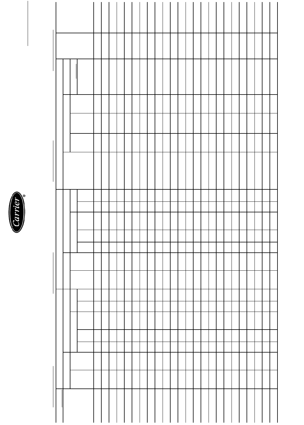
68
REFRIGERATION LOG CARRIER 19XR HERMETIC CENTRIFUGAL REFRIGERATION MACHINE
Plant MACHINE MODEL NO. MACHINE SERIAL NO. REFRIGERANT TYPE
REMARKS: Indicate shutdowns on safety controls, repairs made and oil or refrigerant added or removed. Include amounts.
Fig. 34 — Refrigeration Log
DATE COOLER CONDENSER COMPRESSOR
OPER-
ATO R
INITIALS
REMARKS
TIME
Refrigerant Water Refrigerant Water
BEARING
TEMP
Oil Motor
Press. Temp
Pressure Temp
Press. Temp
Pressure Temp
Press.
Diff.
Temp
(reser-
voir)
Level
FLA
In Out GPM In Out In Out GPM In Out
Amperage
(or vane
position)
DATE
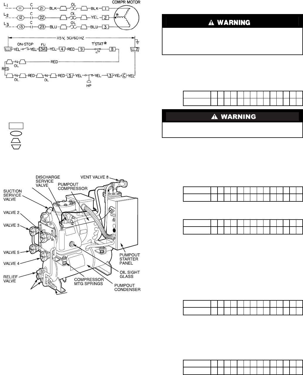
69
Chillers with Storage Tanks — If the chiller has iso-
lation valves, leave them open for the following procedures.
The letter “C” describes a closed valve. See Fig. 17, 18, 29,
and 30.
TRANSFER REFRIGERANT FROM PUMPOUT STOR-
AGE TANK TO CHILLER
1. Equalize refrigerant pressure.
a. Use the PIC II terminate lockout function on the
PUMPDOWN LOCKOUT screen, accessed from
the CONTROL TEST table to turn on the water
pumps and monitor pressures.
b. Close pumpout unit valves 2, 4, 5, 8, and 10, and
close chiller charging valve 7; open chiller isola-
tion valves 11, 12, 13, and 14 (if present).
c. Open pumpout unit/storage tank valves 3 and 6,
open chiller valves 1a and 1b.
d. Slowly open valve 5 to increase chiller pressure to
68 psig 35 psig (141 kPa) for HFC-134a. Feed
refrigerant slowly to prevent freeze up.
e. Open valve 5 fully after the pressure rises above
the freeze point of the refrigerant. Open liquid line
valves 7 and 10 until refrigerant pressure
equalizes.
2. Transfer the remaining refrigerant.
a. Close valve 5 and open valve 4.
b. Turn off the chiller water pumps using the CVC/
ICVC (or manually, if necessary).
c. Turn off the pumpout condenser water, and turn on
the pumpout compressor to push liquid out of the
storage tank.
d. Close liquid line valve 7.
e. Turn off the pumpout compressor.
f. Close valves 3 and 4.
g. Open valves 2 and 5.
h. Turn on the pumpout condenser water.
i. Run the pumpout compressor until the pumpout
storage tank pressure reaches 5 psig (34 kPa)
(18 in. Hg [40 kPa absolute] if repairing the tank).
j. Turn off the pumpout compressor.
k. Close valves 1a, 1b, 2, 5, 6, and 10.
l. Turn off pumpout condenser water.
If the chilled water and condenser water pumps are not
controlled by the PIC II, these pumps must be started and
stopped manually at the appropriate times during the refrig-
erant transfer procedure.
VALVE 1a 1b 2 3 4 5 6 7 8 10 11 12 13 14
CONDITION CCCCCC
Follow Steps d and e carefully to prevent damage from
freeze-up.
VALVE 1a 1b 2 3 4 5 6 7 8 10 11 12 13 14
CONDITION CC C
VALVE 1a 1b 2 3 4 5 6 7 8 10 11 12 13 14
CONDITION CCC
VALVE 1a 1b 2 3 4 5 6 7 8 10 11 12 13 14
CONDITION CC CC
VALVE 1a 1b 2 3 4 5 6 7 8 10 11 12 13 14
CONDITION CCCCCCCCCC
OIL RETURN
LINE
CONNECTION
CONDENSER
WATER
CONNECTIONS
REFRIGERANT
INLET VALVE
LEGEND
*Bimetal thermal protector imbedded in motor winding.
Fig. 35 — 19XR Pumpout Unit Wiring Schematic
C—Contactor
FU —Fuse, 3 Amps
HP —High-Pressure Cutout
OL —Compressor Overload
T’STAT —Internal Thermostat
Compressor Terminal
Contactor Terminal
Overload Terminal
Pumpout Unit Terminal
Fig. 36 — Optional Pumpout Unit
70
TRANSFER REFRIGERANT FROM CHILLER TO PUMP-
OUT STORAGE TANK
1. Equalize refrigerant pressure.
a. Valve positions:
b. Slowly open valve 5. When the pressures are
equalized, open liquid line valve 7 to allow liquid
refrigerant to drain by gravity into the pumpout
storage tank.
2. Transfer the remaining liquid.
a. Turn off the pumpout condenser water. Place the
valves in the following positions:
b. Run the pumpout compressor for approximately
30 minutes; then close valve 10.
c. Turn off the pumpout compressor.
3. Remove any remaining refrigerant.
a. Turn on the chiller water pumps using the PUMP-
DOWN LOCKOUT screen, accessed from the
CONTROL TEST table. Turn on the pumps manu-
ally, if they are not controlled by the PIC II.
b. Turn on the pumpout condenser water.
c. Place valves in the following positions:
d. Run the pumpout compressor until the chiller pres-
sure reaches 30 psig (207 kPa) for HFC-134a.
Then, shut off the pumpout compressor. Warm
condenser water will boil off any entrapped liquid
refrigerant and the chiller pressure will rise.
e. When the pressure rises to 40 psig (276 kPa) for
HFC-134a, turn on the pumpout compressor until
the pressure again reaches 30 psig (207 kPa), and
then turn off the pumpout compressor. Repeat this
process until the pressure no longer rises. Then,
turn on the pumpout compressor and pump until
the pressure reaches18 in. Hg. (40 kPa absolute).
f. Close valves 1a, 1b, 3, 4, 6, 7, and 10.
g. Turn off the pumpout condenser water and con-
tinue to use the PIC II PUMPDOWN LOCKOUT
screen functions, which lock out the chiller com-
pressor for operation.
4. Establish a vacuum for service.
To conserve refrigerant, operate the pumpout compressor
until the chiller pressure is reduced to 18 in. Hg vac., ref
30 in. bar. (40 kPa abs.) following Step 3e.
Chillers with Isolation Valves
TRANSFER ALL REFRIGERANT TO CHILLER CON-
DENSER VESSEL — For chillers with isolation valves,
refrigerant can be stored in one chiller vessel or the other with-
out the need for an external storage tank.
1. Push refrigerant into the chiller condenser.
a. Valve positions:
b. Using the PIC II controls, turn off the chiller water
pumps and pumpout condenser water. If the chiller
water pumps are not controlled through the PIC II,
turn them off manually.
c. Turn on the pumpout compressor to push the liquid
refrigerant out of the chiller cooler vessel.
d. When all liquid refrigerant has been pushed into
the chiller condenser vessel, close chiller isolation
valve 11.
e. Access the PUMPDOWN LOCKOUT screen on
the PIC II CONTROL TEST table to turn on the
chiller water pumps. If the chiller water pumps
are not controlled by the PIC II, turn them on
manually.
f. Turn off the pumpout compressor.
2. Evacuate the refrigerant gas from chiller cooler vessel.
a. Close pumpout compressor valves 2 and 5, and
open valves 3 and 4.
b. Turn on the pumpout condenser water.
c. Run the pumpout compressor until the chiller
cooler vessel pressure reaches 18 in. Hg vac
(40 kPa abs.). Monitor pressures on the CVC/
ICVC and on refrigerant gages.
d. Close valve 1a.
e. Turn off the pumpout compressor.
f. Close valves 1b, 3, and 4.
g. Turn off the pumpout condenser water.
h. Proceed to the PUMPDOWN/LOCKOUT function
accessed from the CONTROL TEST table to turn
off the chiller water pumps and lock out the chiller
compressor. Turn off the chiller water pumps man-
ually if they are not controlled by the PIC II.
TRANSFER ALL REFRIGERANT TO CHILLER
COOLER VESSEL
1. Push the refrigerant into the chiller cooler vessel.
a. Valve positions:
b. Turn off the chiller water pumps (either through
the PIC II controls or manually, if necessary) and
the pumpout condenser water.
c. Turn on the pumpout compressor to push the
refrigerant out of the chiller condenser.
d. When all liquid refrigerant is out of the chiller con-
denser, close the cooler isolation valve 11.
e. Turn off the pumpout compressor.
VALVE 1a 1b 2 3 4 5 6 7 8 10 11 12 13 14
CONDITION CCCCC
VALVE 1a 1b 2 3 4 5 6 7 8 10 11 12 13 14
CONDITION CC C
VALVE 1a 1b 2 3 4 5 6 7 8 10 11 12 13 14
CONDITION CC C
VALVE 1a 1b 2 3 4 5 6 7 8 10 11 12 13 14
CONDITION CC CC
VALVE 1a 1b 2 3 4 5 6 7 8 10 11 12 13 14
CONDITION CCCC
VALVE 1a 1b 2 3 4 5 6 7 8 10 11 12 13 14
CONDITION CCCCCCCCCC
VALVE 1a1b 2 3 4 5 8 11121314
CONDITION CC C CCC
VALVE 1a1b 2 3 4 5 8 11121314
CONDITION C CCCCCC
VALVE 1a1b 2 3 4 5 8 11121314
CONDITION CCCCCCCCCCC
VALVE 1a1b 2 3 4 5 8 11121314
CONDITION CCCCCC
71
2. Evacuate the refrigerant gas from the chiller condenser
vessel.
a. Access the PUMPDOWN LOCKOUT function
accessed from the CVC/ICVC CONTROL TEST
table to turn on the chiller water pumps. Turn the
chiller water pumps on manually if they are not
controlled by the PIC II.
b. Close pumpout unit valves 3 and 4; open valves 2
and 5.
c. Turn on the pumpout condenser water.
d. Run the pumpout compressor until the chiller
condenser pressure reaches 18 in. Hg vac (40 kPa
abs.). Monitor pressure at the CVC/ICVC and at
refrigerant gages.
e. Close valve 1b.
f. Turn off the pumpout compressor.
g. Close valves 1a, 2, and 5.
h. Turn off the pumpout condenser water.
i. Proceed to the PUMPDOWN LOCKOUT test
from the CVC/ICVC CONTROL TEST table to
turn off the chiller water pumps and lock out the
chiller compressor. Turn off the chiller water
pumps manually if they are not controlled by the
PIC II.
RETURN CHILLER TO NORMAL OPERATING
CONDITIONS
1. Ensure vessel that was opened has been evacuated.
2. Access the TERMINATE LOCKOUT function CVC/
ICVC from the CONTROL TEST table to view vessel
pressures and turn on chiller water pumps. If the chiller
water pumps are not controlled by the PIC II, turn them
on manually.
3. Open valves 1a, 1b, and 3.
4. Slowly open valve 5, gradually increasing pressure in the
evacuated vessel to 35 psig (141 kPa). Feed refrigerant
slowly to prevent tube freeze up.
5. Leak test to ensure vessel integrity.
6. Open valve 5 fully.
7. Open valve 11 to equalize the liquid refrigerant level be-
tween the vessels.
8. Close valves 1a, 1b, 3, and 5.
9. Open isolation valves 12, 13, and 14 (if present).
10. Proceed to the TERMINATE LOCKOUT screen (access-
ed from the CONTROL TEST table) to turn off the water
pumps and enable the chiller compressor for start-up. If
the chiller water pumps are not controlled by the PIC II,
turn them off manually.
GENERAL MAINTENANCE
Refrigerant Properties — The standard refrigerant for
the 19XR chiller is HFC-134a. At normal atmospheric pres-
sure, HFC-134a will boil at –14 F (–25 C) and must, therefore,
be kept in pressurized containers or storage tanks. The refriger-
ant is practically odorless when mixed with air and is noncom-
bustible at atmospheric pressure. Read the Material Safety
Data Sheet and the latest ASHRAE Safety Guide for Mechani-
cal Refrigeration to learn more about safe handling of this
refrigerant.
Adding Refrigerant — Follow the procedures de-
scribed in Trim Refrigerant Charge section, page 72.
Removing Refrigerant — If the optional pumpout sys-
tem is used, the 19XR refrigerant charge may be transferred to
a pumpout storage tank or to the chiller condenser or cooler
vessels. Follow the procedures in the Pumpout and Refrigerant
Transfer Procedures section when transferring refrigerant from
one vessel to another.
Adjusting the Refrigerant Charge — If the addi-
tion or removal of refrigerant is required to improve chiller per-
formance, follow the procedures given under the Trim Refrig-
erant Charge section, page 72.
Refrigerant Leak Testing — Because HFC-134a is
above atmospheric pressure at room temperature, leak testing
can be performed with refrigerant in the chiller. Use an elec-
tronic halide leak detector, soap bubble solution, or ultrasonic
leak detector. Ensure that the room is well ventilated and free
from concentration of refrigerant to keep false readings to a
minimum. Before making any necessary repairs to a leak,
transfer all refrigerant from the leaking vessel.
Leak Rate — It is recommended by ASHRAE that chillers
be taken off line immediately and repaired if the refrigerant
leak rate for the entire chiller is more than 10% of the operating
refrigerant charge per year.
In addition, Carrier recommends that leaks totalling less
than the above rate but more than a rate of 0.1% of the total
charge per year should be repaired during annual maintenance
or whenever the refrigerant is transferred for other service
work.
Test After Service, Repair, or Major Leak — If
all the refrigerant has been lost or if the chiller has been opened
for service, the chiller or the affected vessels must be pressure
tested and leak tested. Refer to the Leak Test Chiller section to
perform a leak test.
VALVE 1a 1b 2 3 4 5 8 11 12 13 14
CONDITION CC CCCCC
VALVE 1a 1b 2 3 4 5 8 11 12 13 14
CONDITION CCCCCCCCCCC
VALVE 1a 1b 2 3 4 5 8 11 12 13 14
CONDITION C CCCCCCC
VALVE 1a 1b 2 3 4 5 8 11 12 13 14
CONDITION C C CCCCC
VALVE 1a 1b 2 3 4 5 8 11 12 13 14
CONDITION CCCCCCC
HFC-134a will dissolve oil and some nonmetallic materi-
als, dry the skin, and, in heavy concentrations, may dis-
place enough oxygen to cause asphyxiation. When
handling this refrigerant, protect the hands and eyes and
avoid breathing fumes.
Always use the compressor pumpdown function in the
Control Test table to turn on the cooler pump and lock out
the compressor when transferring refrigerant. Liquid refrig-
erant may flash into a gas and cause possible freeze-up
when the chiller pressure is below 30 psig (207 kPa) for
HFC-134a.
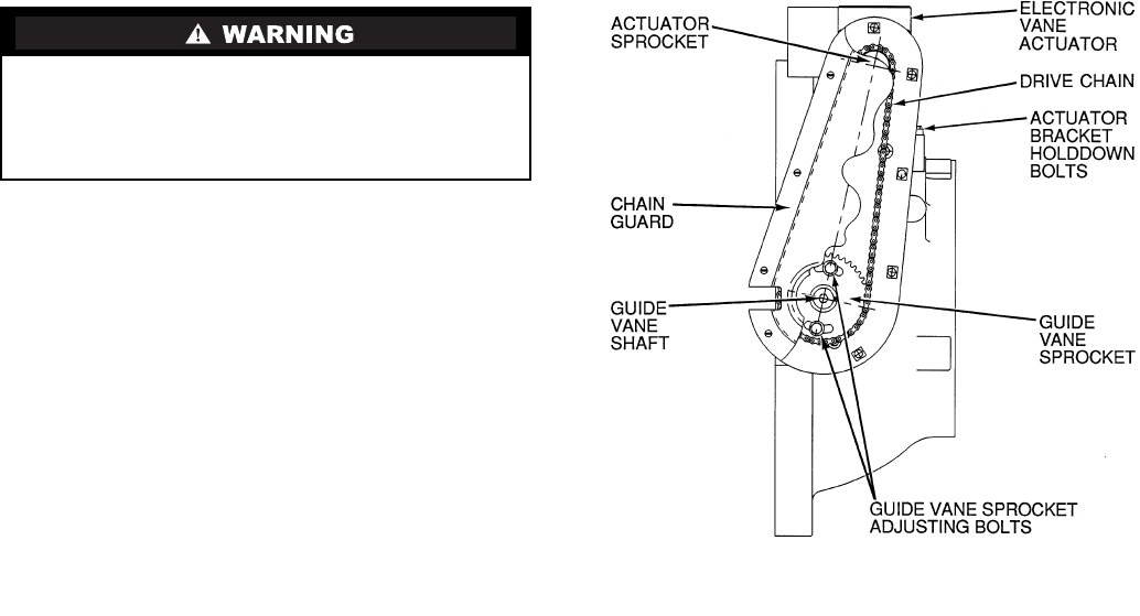
72
TESTING WITH REFRIGERANT TRACER — Use an en-
vironmentally acceptable refrigerant as a tracer for leak test
procedures. Use dry nitrogen to raise the machine pressure to
leak testing levels.
TESTING WITHOUT REFRIGERANT TRACER — An-
other method of leak testing is to pressurize with nitrogen only
and to use a soap bubble solution or an ultrasonic leak detector
to determine if leaks are present.
TO PRESSURIZE WITH DRY NITROGEN
NOTE: Pressurizing with dry nitrogen for leak testing should
not be done if the full refrigerant charge is in the vessel
because purging the nitrogen is very difficult.
1. Connect a copper tube from the pressure regulator on the
cylinder to the refrigerant charging valve. Never apply
full cylinder pressure to the pressurizing line. Follow the
listed sequence.
2. Open the charging valve fully.
3. Slowly open the cylinder regulating valve.
4. Observe the pressure gage on the chiller and close the
regulating valve when the pressure reaches test level. Do
not exceed 140 psig (965 kPa).
5. Close the charging valve on the chiller. Remove the cop-
per tube if it is no longer required.
Repair the Leak, Retest, and Apply Standing
Vacuum Test — After pressurizing the chiller, test for
leaks with an electronic halide leak detector, soap bubble solu-
tion, or an ultrasonic leak detector. Bring the chiller back to at-
mospheric pressure, repair any leaks found, and retest.
After retesting and finding no leaks, apply a standing vacu-
um test. Then dehydrate the chiller. Refer to the Standing Vacu-
um Test and Chiller Dehydration section (pages 50 and 53) in
the Before Initial Start-Up section.
Checking Guide Vane Linkage — When the chiller
is off, the guide vanes are closed and the actuator mechanism is
in the position shown in Fig. 37. If slack develops in the drive
chain, do the following to eliminate backlash:
1. With the chiller shut down and the actuator fully closed,
remove the chain guard and loosen the actuator bracket
hold-down bolts.
2. Loosen guide vane sprocket adjusting bolts.
3. Pry bracket upwards to remove slack, then retighten the
bracket hold-down bolts.
4. Retighten the guide vane sprocket adjusting bolts. Ensure
that the guide vane shaft is rotated fully in the clockwise
direction in order close it fully.
Trim Refrigerant Charge — If, to obtain optimal chill-
er performance, it becomes necessary to adjust the refrigerant
charge, operate the chiller at design load and then add or re-
move refrigerant slowly until the difference between the leav-
ing chilled water temperature and the cooler refrigerant tem-
perature reaches design conditions or becomes a minimum. Do
not overcharge.
Refrigerant may be added either through the storage tank or
directly into the chiller as described in the Charge Refrigerant
into Chiller section.
To remove any excess refrigerant, follow the procedure in
Transfer Refrigerant from Chiller to Pumpout Storage Tank
section, Steps 1a and b, page 70.
WEEKLY MAINTENANCE
Check the Lubrication System — Mark the oil lev-
el on the reservoir sight glass, and observe the level each week
while the chiller is shut down.
If the level goes below the lower sight glass, check the oil
reclaim system for proper operation. If additional oil is re-
quired, add it through the oil drain charging valve (Fig. 2). A
pump is required when adding oil against refrigerant pressure.
The oil charge for the 19XR compressor depends on the com-
pressor Frame size:
•Frame 2 compressor — 5 gal (18.9 L)
•Frame 3 compressor — 8 gal (30 L)
•Frame 4 compressor — 10 gal (37.8 L)
•Frame 5 compressor — 18 gal (67.8 L)
The added oil must meet Carrier specifications for the
19XR. Refer to Changing Oil Filter and Oil Changes section
on page 73. Any additional oil that is added should be logged
by noting the amount and date. Any oil that is added due to oil
loss that is not related to service will eventually return to the
sump. It must be removed when the level is high.
An oil heater is controlled by the PIC II to maintain oil tem-
perature (see the Controls section) when the compressor is off.
The CVC/ICVC COMPRESS screen displays whether the
heater is energized or not. The heater is energized if the OIL
HEATER RELAY parameter reads ON. If the PIC II shows that
the heater is energized and if the sump is still not heating up,
the power to the oil heater may be off or the oil level may be
too low. Check the oil level, the oil heater contactor voltage,
and oil heater resistance.
The PIC II does not permit compressor start-up if the oil
temperature is too low. The PIC II continues with start-up only
after the temperature is within allowable limits.
HFC-134a should not be mixed with air or oxygen and
pressurized for leak testing. In general, this refrigerant
should not be present with high concentrations of air or
oxygen above atmospheric pressures, because the mixture
can undergo combustion.
Fig. 37 —Guide Vane Actuator Linkage

73
SCHEDULED MAINTENANCE
Establish a regular maintenance schedule based on your ac-
tual chiller requirements such as chiller load, run hours, and
water quality. The time intervals listed in this section are
offered as guides to service only.
Service Ontime — The CVC/ICVC will display a SER-
VICE ONTIME value on the MAINSTAT screen. This value
should be reset to zero by the service person or the operator
each time major service work is completed so that the time
between service can be viewed and tracked.
Inspect the Control Panel — Maintenance consists of
general cleaning and tightening of connections. Vacuum the
cabinet to eliminate dust build-up. If the chiller control mal-
functions, refer to the Troubleshooting Guide section for con-
trol checks and adjustments.
Check Safety and Operating Controls Monthly —
To ensure chiller protection, the automated Control Test
should be performed at least once per month. See Table 3
for safety control settings. See Table 9 for Control Test
functions.
Changing Oil Filter — Change the oil filter on a
yearly basis or when the chiller is opened for repairs. The
19XR has an isolatable oil filter so that the filter may be
changed with the refrigerant remaining in the chiller. Use
the following procedure:
1. Ensure the compressor is off and the disconnect for the
compressor is open.
2. Disconnect the power to the oil pump.
3. Close the oil filter isolation valves located behind power
panel on top of oil pump assembly.
4. Connect an oil charging hose from the oil charging valve
(Fig. 2) and place the other end in a clean container suit-
able for used oil. The oil drained from the filter housing
should be used as an oil sample and sent to a laboratory
for proper analysis. Do not contaminate this sample.
5. Slowly open the charging valve to drain the oil from the
housing.
6. Once all oil has been drained, place some rags or absor-
bent material under the oil filter housing to catch any
drips once the filter is opened. Remove the 4 bolts from
the end of the filter housing and remove the filter cover.
7. Remove the filter retainer by unscrewing the retainer nut.
The filter may now be removed and disposed of properly.
8. Replace the old filter with a new filter. Install the filter re-
tainer and tighten down the retainer nut. Install the filter
cover and tighten the 4 bolts.
9. Evacuate the filter housing by placing a vacuum pump on
the charging valve. Follow the normal evacuation proce-
dures. Shut the charging valve when done and reconnect
the valve so that new oil can be pumped into the filter
housing. Fill with the same amount that was removed;
then close the charging valve.
10. Remove the hose from the charging valve, open the isola-
tion valves to the filter housing, and turn on the power to
the pump and the motor.
Oil Specification — If oil is added, it must meet the fol-
lowing Carrier specifications:
Oil Type for units using R-134a . . . . . . . . . . . . . . . . . . Inhibited
polyolester-based synthetic
compressor oil formatted for
use with HFC, gear-driven,
hermetic compressors.
ISO Viscosity Grade . . . . . . . . . . . . . . . . . . . . . . . . . . . . . . . . 68
The polyolester-based oil (P/N: PP23BZ103) may be
ordered from your local Carrier representative.
Oil Changes — Carrier recommends changing the oil af-
ter the first year of operation and every five years thereafter as
a minimum in addition to a yearly oil analysis. However, if a
continuous oil monitoring system is functioning and a yearly
oil analysis is performed, the time between oil changes can be
extended.
TO CHANGE THE OIL
1. Transfer the refrigerant into the chiller condenser vessel
(for isolatable vessels) or to a pumpout storage tank.
2. Mark the existing oil level.
3. Open the control and oil heater circuit breaker.
4. When the chiller pressure is 5 psig (34 kPa) or less, drain
the oil reservoir by opening the oil charging valve
(Fig. 2). Slowly open the valve against refrigerant
pressure.
5. Change the oil filter at this time. See Changing Oil Filter
section.
6. Change the refrigerant filter at this time, see the next sec-
tion, Refrigerant Filter.
7. Charge the chiller with oil. Charge until the oil level is
equal to the oil level marked in Step 2. Turn on the power
to the oil heater and let the PIC II warm it up to at least
140 F (60 C). Operate the oil pump manually, using the
Control Test function, for 2 minutes. For shutdown condi-
tions, the oil level should be full in the lower sight glass.
If the oil level is above 1/2 full in the upper sight glass, re-
move the excess oil. The oil level should now be equal to
the amount shown in Step 2.
Refrigerant Filter — A refrigerant filter/drier, located on
the refrigerant cooling line to the motor, should be changed
once a year or more often if filter condition indicates a need for
more frequent replacement. Change the filter by closing the fil-
ter isolation valves (Fig. 4) and slowly opening the flare fittings
with a wrench and back-up wrench to relieve the pressure. A
moisture indicator sight glass is located beyond this filter to in-
dicate the volume and moisture in the refrigerant. If the mois-
ture indicator indicates moisture, locate the source of water im-
mediately by performing a thorough leak check.
Oil Reclaim Filter — The oil reclaim system has a
strainer on the eductor suction line, a strainer on the discharge
pressure line, and a filter on the cooler scavenging line.
Replace the filter once per year or more often if filter condition
indicates a need for more frequent replacement. Change the fil-
ter by closing the filter isolation valves and slowly opening the
flare fitting with a wrench and back-up wrench to relieve the
pressure. Change the strainers once every 5 years or whenever
refrigerant is evacuated from the cooler.
Ensure power to the control center is off when cleaning and
tightening connections inside the control panel.
The oil filter housing is at a high pressure. Relieve this
pressure slowly.
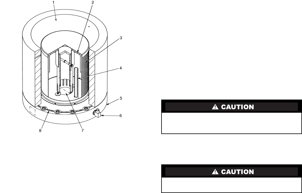
74
Inspect Refrigerant Float System — Perform this
inspection every 5 years or when the condenser is opened for
service.
1. Transfer the refrigerant into the cooler vessel or into a
pumpout storage tank.
2. Remove the float access cover.
3. Clean the chamber and valve assembly thoroughly. Be
sure the valve moves freely. Ensure that all openings are
free of obstructions.
4. Examine the cover gasket and replace if necessary.
See Fig. 38 for a view of the float valve design. For linear
float valve designs, inspect the orientation of the float slide
pin. It must be pointed toward the bubbler tube for proper
operation.
Inspect Relief Valves and Piping — The relief valves
on this chiller protect the system against the potentially danger-
ous effects of overpressure. To ensure against damage to the
equipment and possible injury to personnel, these devices must
be kept in peak operating condition.
As a minimum, the following maintenance is required.
1. At least once a year, disconnect the vent piping at the
valve outlet and carefully inspect the valve body and
mechanism for any evidence of internal corrosion or rust,
dirt, scale, leakage, etc.
2. If corrosion or foreign material is found, do not attempt to
repair or recondition. Replace the valve.
3. If the chiller is installed in a corrosive atmosphere or the
relief valves are vented into a corrosive atmosphere, in-
spect the relief valves at more frequent intervals.
Compressor Bearing and Gear Maintenance —
The key to good bearing and gear maintenance is proper
lubrication. Use the proper grade of oil, maintained at rec-
ommended level, temperature, and pressure. Inspect the
lubrication system regularly and thoroughly.
To inspect the bearings, a complete compressor teardown is
required. Only a trained service technician should remove and
examine the bearings. The cover plate on older compressor
bases was used for factory-test purposes and is not usable
for bearing or gear inspection. The bearings and gears should
be examined on a scheduled basis for signs of wear. The
frequency of examination is determined by the hours of chiller
operation, load conditions during operation, and the condition
of the oil and the lubrication system. Excessive bearing wear
can sometimes be detected through increased vibration or
increased bearing temperature. If either symptom appears, con-
tact an experienced and responsible service organization for
assistance.
Inspect the Heat Exchanger Tubes and Flow
Devices
COOLER AND FLOW DEVICES — Inspect and clean the
cooler tubes at the end of the first operating season. Because
these tubes have internal ridges, a rotary-type tube cleaning
system is needed to fully clean the tubes. Inspect the tubes’
condition to determine the scheduled frequency for future
cleaning and to determine whether water treatment in the
chilled water/brine circuit is adequate. Inspect the entering and
leaving chilled water temperature sensors and flow devices for
signs of corrosion or scale. Replace a sensor or Schrader fitting
if corroded or remove any scale if found.
CONDENSER AND FLOW DEVICES — Since this water
circuit is usually an open-type system, the tubes may be subject
to contamination and scale. Clean the condenser tubes with a
rotary tube cleaning system at least once per year and more of-
ten if the water is contaminated. Inspect the entering and leav-
ing condenser water sensors and flow devices for signs of cor-
rosion or scale. Replace the sensor or Schrader fitting if corrod-
ed or remove any scale if found.
Higher than normal condenser pressures, together with the
inability to reach full refrigeration load, usually indicate dirty
tubes or air in the chiller. If the refrigeration log indicates a rise
above normal condenser pressures, check the condenser refrig-
erant temperature against the leaving condenser water tempera-
ture. If this reading is more than what the design difference is
supposed to be, the condenser tubes may be dirty or water flow
may be incorrect. Because HFC-134a is a high-pressure refrig-
erant, air usually does not enter the chiller.
During the tube cleaning process, use brushes specially de-
signed to avoid scraping and scratching the tube wall. Contact
your Carrier representative to obtain these brushes. Do not use
wire brushes.
Water Leaks — The refrigerant moisture indicator on the
refrigerant motor cooling line (Fig. 2) indicates whether there
is water leakage during chiller operation. Water leaks should be
repaired immediately.
Hard scale may require chemical treatment for its preven-
tion or removal. Consult a water treatment specialist for
proper treatment.
The chiller must be dehydrated after repair of water leaks.
See Chiller Dehydration section, page 53.
LEGEND
Fig. 38 — 19XR Float Valve Design
1—Refrigerant Inlet from FLASC Chamber
2—Linear Float Assembly
3—Float Screen
4—Bubble Line
5—Float Cover
6—Bubble Line Connection
7—Refrigerant Outlet to Cooler
8—Gasket
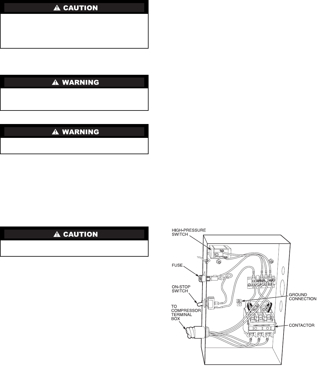
75
Water Treatment — Untreated or improperly treated wa-
ter may result in corrosion, scaling, erosion, or algae. The ser-
vices of a qualified water treatment specialist should be ob-
tained to develop and monitor a treatment program.
Inspect the Starting Equipment — Before working
on any starter, shut off the chiller, open and tag all disconnects
supplying power to the starter.
Inspect starter contact surfaces for wear or pitting on
mechanical-type starters. Do not sandpaper or file silverplated
contacts. Follow the starter manufacturer’s instructions for
contact replacement, lubrication, spare parts ordering, and oth-
er maintenance requirements.
Periodically vacuum or blow off accumulated debris on the
internal parts with a high-velocity, low-pressure blower.
Power connections on newly installed starters may relax
and loosen after a month of operation. Turn power off and re-
tighten. Recheck annually thereafter.
Check Pressure Transducers — Once a year, the
pressure transducers should be checked against a pressure gage
reading. Check all eight transducers: the 2 oil differential pres-
sure transducers, the condenser pressure transducer, the cooler
pressure transducer, and the waterside pressure transducers
(consisting of 4 flow devices: 2 cooler, 2 condenser).
Note the evaporator and condenser pressure readings on the
HEAT_EX screen on the CVC/ICVC (EVAPORATOR PRES-
SURE and CONDENSER PRESSURE). Attach an accurate set
of refrigeration gages to the cooler and condenser Schrader fit-
tings. Compare the two readings. If there is a difference in
readings, the transducer can be calibrated as described in the
Troubleshooting Guide section. Oil differential pressure (OIL
PUMP DELTA P on the COMPRESS screen) should be zero
whenever the compressor is off.
Optional Pumpout System Maintenance — For
pumpout unit compressor maintenance details, refer to the
06D, 07D Installation, Start-Up, and Service Instructions.
OPTIONAL PUMPOUT COMPRESSOR OIL CHARGE —
Use oil conforming to Carrier specifications for reciprocat-
ing compressor usage. Oil requirements are as follows:
ISO Viscosity . . . . . . . . . . . . . . . . . . . . . . . . . . . . . . . . . . . . . . 68
Carrier Part Number . . . . . . . . . . . . . . . . . . . . . . . . PP23BZ103
The total oil charge, 4.5 pints (2.6 L), consists of 3.5 pints
(2.0 L) for the compressor and one additional pint (0.6 L) for
the oil separator.
Oil should be visible in one of the compressor sight glasses
during both operation and at shutdown. Always check the oil
level before operating the compressor. Before adding or chang-
ing oil, relieve the refrigerant pressure as follows:
1. Attach a pressure gage to the gage port of either compres-
sor service valve (Fig. 36).
2. Close the suction service valve and open the discharge
line to the storage tank or the chiller.
3. Operate the compressor until the crankcase pressure
drops to 2 psig (13 kPa).
4. Stop the compressor and isolate the system by closing the
discharge service valve.
5. Slowly remove the oil return line connection (Fig. 36).
Add oil as required.
6. Replace the connection and reopen the compressor ser-
vice valves.
OPTIONAL PUMPOUT SAFETY CONTROL SETTINGS
(Fig. 39) — The optional pumpout system high-pressure
switch opens at 161 psig (1110 kPa) and closes at 130 psig
(896 kPa). Check the switch setting by operating the pumpout
compressor and slowly throttling the pumpout condenser
water.
Ordering Replacement Chiller Parts — When
ordering Carrier specified parts, the following information
must accompany an order:
•chiller model number and serial number
•name, quantity, and part number of the part required
•delivery address and method of shipment.
Water must be within design flow limits, clean, and treated
to ensure proper chiller performance and reduce the poten-
tial of tube damage due to corrosion, scaling, erosion, and
algae. Carrier assumes no responsibility for chiller damage
resulting from untreated or improperly treated water.
The disconnect on the starter front panel does not deener-
gize all internal circuits. Open all internal and remote dis-
connects before servicing the starter.
Never open isolating knife switches while equipment is
operating. Electrical arcing can cause serious injury.
Loose power connections can cause voltage spikes, over-
heating, malfunctioning, or failures.
Fig. 39 — Optional Pumpout System Controls
76
TROUBLESHOOTING GUIDE
Overview — The PIC II has many features to help the op-
erator and technician troubleshoot a 19XR chiller.
•The CVC/ICVC shows the chiller’s actual operating con-
ditions and can be viewed while the unit is running.
•The CVC/ICVC default screen freezes when an alarm
occurs. The freeze enables the operator to view the
chiller conditions at the time of alarm. The STATUS
screens continue to show current information. Once all
alarms have been cleared (by correcting the problems
and pressing the softkey), the CVC/ICVC
default screen returns to normal operation.
•The CONTROL ALGORITHM STATUS screens (which
include the CAPACITY, OVERRIDE, LL_MAINT,
ISM_HIST, LOADSHED, WSMDEFME, and
OCCDEFCM screens) display information that helps to
diagnose problems with chilled water temperature
control, chilled water temperature control overrides, hot
gas bypass, surge algorithm status, and time schedule
operation.
•The control test feature facilitates the proper operation
and test of temperature sensors, pressure transducers, the
guide vane actuator, oil pump, water pumps, tower con-
trol, and other on/off outputs while the compressor is
stopped. It also has the ability to lock off the compressor
and turn on water pumps for pumpout operation. The
CVC/ICVC shows the temperatures and pressures
required during these operations.
•From other SERVICE tables, the operator/technician can
access configured items, such as chilled water resets,
override set points, etc.
•If an operating fault is detected, an alarm message is gen-
erated and displayed on the CVC/ICVC default screen.
A more detailed message — along with a diagnostic
message — is also stored into the ALARM HISTORY
table.
Checking Display Messages — The first area to
check when troubleshooting the 19XR is the CVC/ICVC dis-
play. If the alarm light is flashing, check the primary and sec-
ondary message lines on the CVC/ICVC default screen
(Fig. 14). These messages will indicate where the fault is oc-
curring. These messages contain the alarm message with a
specified code. This code or state appears with each alarm and
alert message. The ALARM HISTORY table on the CVC/
ICVC SERVICE menu also contains an alarm message to fur-
ther expand on the alarm. For a complete list of possible alarm
messages, see Table 11. If the alarm light starts to flash while
accessing a menu screen, press the softkey to return to
the default screen to read the alarm message. The STATUS
screen can also be accessed to determine where an alarm exists.
Checking Temperature Sensors — All temperature
sensors are thermistor-type sensors. This means that the resis-
tance of the sensor varies with temperature. All sensors have
the same resistance characteristics. If the controls are on, deter-
mine sensor temperature by measuring voltage drop; if the con-
trols are powered off, determine sensor temperature by measur-
ing resistance. Compare the readings to the values listed in
Table 12A or 12B.
RESISTANCE CHECK — Turn off the control power and,
from the module, disconnect the terminal plug of the sensor in
question. With a digital ohmmeter, measure sensor resistance
between receptacles as designated by the wiring diagram. The
resistance and corresponding temperature are listed in
Table 12A or 12B. Check the resistance of both wires to
ground. This resistance should be infinite.
VOLTAGE DROP — The voltage drop across any energized
sensor can be measured with a digital voltmeter while the con-
trol is energized. Table 12A or 12B lists the relationship be-
tween temperature and sensor voltage drop (volts dc measured
across the energized sensor). Exercise care when measuring
voltage to prevent damage to the sensor leads, connector plugs,
and modules. Sensors should also be checked at the sensor
plugs. Check the sensor wire at the sensor for 5 vdc if the con-
trol is powered on.
CHECK SENSOR ACCURACY — Place the sensor in a
medium of known temperature and compare that temperature
to the measured reading. The thermometer used to determine
the temperature of the medium should be of laboratory quality
with 0.5° F (.25° C) graduations. The sensor in question should
be accurate to within 2° F (1.2° C).
See Fig. 9 for sensor locations. The sensors are immersed
directly in the refrigerant or water circuits. The wiring at each
sensor is easily disconnected by unlatching the connector.
These connectors allow only one-way connection to the sensor.
When installing a new sensor, apply a pipe sealant or thread
sealant to the sensor threads.
DUAL TEMPERATURE SENSORS — For servicing con-
venience, there are 2 sensors each on the bearing and motor
temperature sensors. If one of the sensors is damaged, the other
can be used by simply moving a wire. The number 2 terminal
in the sensor terminal box is the common line. To use the sec-
ond sensor, move the wire from the number 1 position to the
number 3 position.
Checking Pressure Transducers
UNITS EQUIPPED WITH CVC — There are 8 pressure
transducers on 19XR chillers. They determine cooler, condens-
er, oil pressure, and cooler and condenser flow. The cooler and
condenser transducers are also used by the PIC II to determine
the refrigerant temperatures. The oil supply pressure transducer
value and the oil transmission sump pressure transducer value
difference is calculated by the CCM. The CVC module then
displays the differential pressure. In effect, the CVC reads only
one input for oil pressure for a total of 5 pressure inputs: cooler
pressure, condenser pressure, oil differential pressure, cooler
waterside differential pressure, and condenser waterside differ-
ential pressure. See the Check Pressure Transducers section
(page 75) under Scheduled Maintenance.
UNITS EQUIPPED WITH ICVC — There are 6 factory-
installed pressure transducers, with inputs available for both
cooler and The ICVC software will display a default reading of
26 psi during start-up and operation. An additional transducer,
factory installed in the bottom of the cooler barrel, will read as
EVAPORATOR SACTURATION TEMP on the HEAT_EX
DISPLAY screen. This provides additional protection against a
loss of water flow condition.
These pressure transducers can be calibrated if necessary. It
is not usually necessary to calibrate at initial start-up.
However, at high altitude locations, it is necessary to calibrate
the transducers to ensure the proper refrigerant temperature/
pressure relationship. Each transducer is supplied with 5 vdc
power from the CCM. If the power supply fails, a transducer
voltage reference alarm occurs. If the transducer reading is
suspected of being faulty, check the supply voltage. It should
be 5 vdc ±.5 v displayed in CONTROL TEST under CCM
Pressure Transducers. If the supply voltage is correct, the trans-
ducer should be recalibrated or replaced.
RESET
EXIT
Relieve all refrigerant pressure or drain the water before
replacing the temperature sensors.
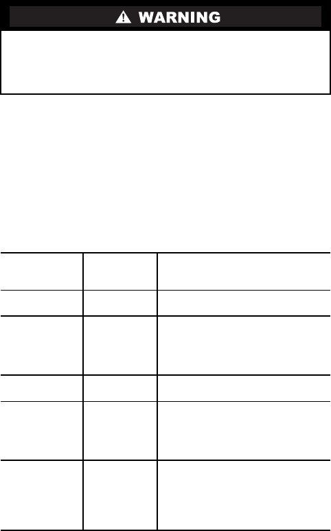
77
TRANSDUCER REPLACEMENT — Since the transducers
are mounted on Schrader-type fittings, there is no need to re-
move refrigerant from the vessel when replacing the transduc-
ers. Disconnect the transducer wiring. Do not pull on the trans-
ducer wires. Unscrew the transducer from the Schrader fitting.
When installing a new transducer, do not use pipe sealer
(which can plug the sensor). Put the plug connector back on the
sensor and snap into place. Check for refrigerant leaks.
Control Algorithms Checkout Procedure — One
of the tables on the CVC/ICVC SERVICE menu is CON-
TROL ALGORITHM STATUS. The maintenance screens
may be viewed from the CONTROL ALGORITHM STATUS
table to see how a particular control algorithm is operating.
These maintenance screens are very useful in helping to de-
termine how the control temperature is calculated and guide
vane positioned and for observing the reactions from load
changes, control point overrides, hot gas bypass, surge preven-
tion, etc. The tables are:
Control Test — The Control Test feature can check all the
thermistor temperature sensors, pressure transducers, pumps
and their associated flow devices, the guide vane actuator, and
other control outputs such as hot gas bypass. The tests can help
to determine whether a switch is defective or a pump relay is
not operating, as well as other useful troubleshooting issues.
During pumpdown operations, the pumps are energized to pre-
vent freeze-up and the vessel pressures and temperatures are
displayed. The Pumpdown/Lockout feature prevents compres-
sor start-up when there is no refrigerant in the chiller or if the
vessels are isolated. The Terminate Lockout feature ends the
Pumpdown/Lockout after the pumpdown procedure is reversed
and refrigerant is added.
LEGEND TO TABLES 11A-11J
Be sure to use a back-up wrench on the Schrader fitting
whenever removing a transducer, since the Schrader fitting
may back out with the transducer, causing a large leak and
possible injury to personnel.
CAPACITY Capacity
Control
This table shows all values used
to calculate the chilled water/brine
control point.
OVERRIDE Override
Status
Details of all chilled water control
override values.
HEAT_EX Surge/
HGBP
Status
The surge and hot gas bypass
control algorithm status is viewed
from this screen. All
values dealing with this control
are displayed.
LL_MAINT LEAD/LAG
Status
Indicates LEAD/LAG operation
status.
OCCDEFCM Time
Schedules
Status
The Local and CCN occupied
schedules are displayed here to
help the operator quickly deter-
mine whether the schedule is in
the “occupied” mode or not.
WSMDEFME Water
System
Manager
Status
The water system manager is a
CCN module that can turn on the
chiller and change the chilled
water control point. This screen
indicates the
status of this system.
CCM —Chiller Control Module
CVC —Chiller Visual Controller
CHW —Chilled Water
ICVC —International Chiller Visual
Control
ISM —Integrated Starter Module
PIC II —Product Integrated Controls II
VFD —Variable Frequency Drive

78
Table 11 — CVC/ICVC Primary and Secondary Messages and
Custom Alarm/Alert Messages with Troubleshooting Guides
A. MANUAL STOP
B. READY TO START
C. IN RECYCLE SHUTDOWN
PRIMARY MESSAGE SECONDARY MESSAGE PROBABLE CAUSE/REMEDY
MANUALLY STOPPED — PRESS CCN OR LOCAL TO START PIC II in OFF mode, press CCN or LOCAL softkey to start unit.
TERMINATE PUMPDOWN MODE TO SELECT CCN OR LOCAL Enter the CONTROL TEST table and select TERMINATE LOCKOUT to
unlock compressor.
SHUTDOWN IN PROGRESS COMPRESSOR UNLOADING Chiller unloading before shutdown due to soft/stop feature.
SHUTDOWN IN PROGRESS COMPRESSOR DEENERGIZED Chiller compressor is being commanded to stop. Water pumps are
deenergized within one minute.
ICE BUILD OPERATION COMPLETE Chiller shutdown from Ice Build operation.
PRIMARY MESSAGE SECONDARY MESSAGE PROBABLE CAUSE/REMEDY
READY TO START IN XX MIN UNOCCUPIED MODE Time schedule for PIC II is unoccupied. Chillers will start only when
occupied.
READY TO START IN XX MIN REMOTE CONTACTS OPEN Remote contacts are open. Close contacts to start.
READY TO START IN XX MIN STOP COMMAND IN EFFECT Chiller START/STOP on MAINSTAT manually forced to stop. Release
point to start.
READY TO START IN XX MIN OCCUPIED MODE Chiller timer counting down. Unit ready to start.
READY TO START IN XX MIN REMOTE CONTACTS CLOSED Chiller timer counting down. Unit ready to start. Remote contact enabled
and closed.
READY TO START IN XX MIN START COMMAND IN EFFECT Chiller START/STOP on MAINSTAT manually forced to start. Release
value to start under normal control.
READY TO START IN XX MIN RECYCLE RESTART PENDING Chiller in recycle mode.
READY TO START UNOCCUPIED MODE Time schedule for PIC II is unoccupied. Chiller will start when occupied.
Make sure the time and date are correct. Change values in TIME AND
DATE screen.
READY TO START REMOTE CONTACTS OPEN Remote contacts have stopped the chiller. Close contacts to start.
READY TO START STOP COMMAND IN EFFECT Chiller START/STOP on MAINSTAT manually forced to stop. Release
point to start.
READY TO START OCCUPIED MODE Chiller timers complete, unit start will commence.
READY TO START REMOTE CONTACTS CLOSED Chiller timer counting down. Unit ready for start.
READY TO START START COMMAND IN EFFECT Chiller START/STOP on MAINSTAT has been manually forced to start.
Chiller will start regardless of time schedule or remote contact status.
STARTUP INHIBITED LOADSHED IN EFFECT CCN loadshed module commanding chiller to stop.
PRIMARY MESSAGE SECONDARY MESSAGE PROBABLE CAUSE/REMEDY
RECYCLE RESTART PENDING OCCUPIED MODE Unit in recycle mode, chilled water temperature is not sufficiently
above set point to start.
RECYCLE RESTART PENDING REMOTE CONTACT CLOSED Unit in recycle mode, chilled water temperature is not sufficiently
above set point to start.
RECYCLE RESTART PENDING START COMMAND IN EFFECT Chiller START/STOP on MAINSTAT manually forced to start, chilled
water temperature is not sufficiently above set point to start.
RECYCLE RESTART PENDING ICE BUILD MODE Chiller in ICE BUILD mode. Chilled fluid temperature is satisfied for
ICE BUILD conditions.
79
Table 11 — CVC/ICVC Primary and Secondary Messages and
Custom Alarm/Alert Messages with Troubleshooting Guides (cont)
D. PRE-START ALERTS: These alerts only delay start-up. When alert is corrected, the start-up will continue. No reset is necessary.
*[LIMIT] is shown on the CVC/ICVC as temperature, pressure, voltage, etc., predefined or selected by the operator as an override or an alert.
[VALUE] is the actual pressure, temperature, voltage, etc., at which the control tripped.
E. START-UP IN PROGRESS
F. NORMAL RUN
STATE PRIMARY
MESSAGE
SECONDARY
MESSAGE
ALARM MESSAGE
PRIMARY CAUSE ADDITIONAL CAUSE/REMEDY
100 PRESTART
ALERT
STARTS LIMIT
EXCEEDED
100->Excessive compressor
starts (8 in 12 hours)
Depress the RESET softkey if additional start is
required. Reassess start-up requirements.
101 PRESTART
ALERT
HIGH BEARING
TEMPERATURE
101->Comp Thrust Bearing
Temp [VALUE] exceeded
limit of [LIMIT]*.
Check oil heater for proper operation.
Check for low oil level, partially closed coil supply
valves, clogged oil filters, etc.
Check the sensor wiring and accuracy.
Check configurable range in SETUP1 screen.
102 PRESTART
ALERT
HIGH MOTOR
TEMPERATURE
102->Comp Motor Winding Temp
[VALUE] exceeded limit
of [LIMIT]*.
Check motor sensors for wiring and accuracy.
Check motor cooling line for proper operation, or
restrictions.
Check for excessive starts within a short time span.
Check configurable range in SETUP1 screen.
103 PRESTART
ALERT
HIGH DISCHARGE
TEMP
103->Comp Discharge Temp
[VALUE] exceeded limit of
[LIMIT]*.
Allow discharge sensor to cool.
Check for sensor wiring and accuracy.
Check for excessive starts.
Check configurable range in SETUP1 screen.
104 PRESTART
ALERT
LOW REFRIGERANT
TEMP
104->Evaporator Refrig Temp
[VALUE] exceeded limit of
[LIMIT]*.
Check transducer wiring and accuracy.
Check for low chilled fluid supply temperatures.
Check refrigerant charge.
105 PRESTART
ALERT
LOW OIL
TEMPERATURE
105->Oil Sump Temp [VALUE]
exceeded limit of [LIMIT]*.
Check oil heater contactor/relay and power.
Check oil level and oil pump operation.
106 PRESTART
ALERT
HIGH CONDENSER
PRESSURE
106->Condenser Pressure
[VALUE] exceeded limit of
[LIMIT]*.
Check transducer wiring and accuracy.
Check for high condenser water temperatures.
107 PRESTART
ALERT
LOW LINE
VOLTAGE
107->Average Line Voltage
[VALUE] exceeded limit of
[LIMIT]*.
Check voltage supply. Check voltage transformers.
Consult power utility if voltage is low.
108 PRESTART
ALERT
HIGH LINE
VOLTAGE
108->Average Line Voltage
[VALUE] exceeded limit of
[LIMIT]*.
Check voltage supply.
Check power transformers.
Consult power utility if voltage is high.
109 PRESTART
ALERT
GUIDE VANE
CALIBRATION
109->Actual Guide Vane
Pos Calibration Required
Before Start-Up
Calibrate guide vane actuator in Control Test.
PRIMARY MESSAGE SECONDARY MESSAGE CAUSE/REMEDY
STARTUP IN PROGRESS OCCUPIED MODE Chiller is starting. Time schedule is occupied.
STARTUP IN PROGRESS REMOTE CONTACT CLOSED Chiller is starting. Remote contacts are enabled and closed.
STARTUP IN PROGRESS START COMMAND IN EFFECT Chiller is starting. Chiller START/STOP in MAINSTAT manually forced to
start.
AUTORESTART IN PROGRESS OCCUPIED MODE Chiller is starting after power failure. Time schedule is occupied.
AUTORESTART IN PROGRESS REMOTE CONTACT CLOSED Chiller is starting after power failure. Remote contacts are enabled and
closed.
AUTORESTART IN PROGRESS START COMMAND IN EFFECT Chiller is starting after power failure. Chiller START/STOP on MAINSTAT
manually forced to start.
PRIMARY MESSAGE SECONDARY MESSAGE CAUSE/REMEDY
RUNNING — RESET ACTIVE 4-20 mA SIGNAL Auto chilled water reset active based on external input.
RUNNING — RESET ACTIVE REMOTE TEMP SENSOR Auto chilled water reset active based on external input.
RUNNING — RESET ACTIVE CHW TEMP DIFFERENCE Auto chilled water reset active based on cooler ∆T.
RUNNING — TEMP CONTROL LEAVING CHILLED WATER Default method of temperature control.
RUNNING — TEMP CONTROL ENTERING CHILLED WATER Entering Chilled Water (ECW) control enabled in TEMP_CTL screen
RUNNING — TEMP CONTROL TEMPERATURE RAMP LOADING Ramp Loading in effect. Use RAMP_DEM screen to modify.
RUNNING — DEMAND LIMITED BY DEMAND RAMP LOADING Ramp Loading in effect. Use RAMP_DEM screen to modify.
RUNNING — DEMAND LIMITED BY LOCAL DEMAND SETPOINT Demand limit set point is less than actual demand.
RUNNING — DEMAND LIMITED BY 4-20 mA SIGNAL Demand limit is active based on external auto demand limit option.
RUNNING — DEMAND LIMITED BY CCN SIGNAL Demand limit is active based on control limit signal from CCN.
RUNNING — DEMAND LIMITED BY LOADSHED/REDLINE Demand limit is active based on LOADSHED screen set-up.
RUNNING — TEMP CONTROL HOT GAS BYPASS Hot gas bypass option is energized. See stall prevention in the control
section.
RUNNING — DEMAND LIMITED BY LOCAL SIGNAL Active demand limit manually overridden on MAINSTAT table.
RUNNING —TEMP CONTROL ICE BUILD MODE Chiller is running under Ice Build temperature control.
80
Table 11 — CVC/ICVC Primary and Secondary Messages and
Custom Alarm/Alert Messages with Troubleshooting Guides (cont)
G. NORMAL RUN WITH OVERRIDES
*[LIMIT] is shown on the CVC/ICVC as the temperature, pressure, voltage, etc., set point predefined or selected by the operator as an override,
alert, or alarm condition. [VALUE] is the actual pressure, temperature, voltage, etc., at which the control has recorded at the time of the fault con-
dition.
H. OUT-OF-RANGE SENSOR ALARMS
STATE PRIMARY
MESSAGE
SECONDARY
MESSAGE
ALARM MESSAGE
PRIMARY CAUSE
ADDITIONAL
CAUSE/REMEDY
120 RUN CAPACITY
LIMITED
HIGH CONDENSER
PRESSURE
120->Condenser Pressure
[VALUE] exceeded limit of [LIMIT]*.
Check for high condenser water temperatures.
Check setting in SETUP1.
121 RUN CAPACITY
LIMITED
HIGH MOTOR
TEMPERATURE
121->Comp Motor Winding Temp
[VALUE] exceeded limit of [LIMIT]*.
Check motor cooling lines.
Check for closed valves.
Check setting in SETUP1.
122 RUN CAPACITY
LIMITED
LOW EVAP
REFRIG TEMP
122->Evaporator Refrig Temp
[VALUE] exceeded limit of [LIMIT]*.
Check refrigerant charge.
Check for low entering cooler temperatures.
123 RUN CAPACITY
LIMITED
HIGH COMPRESSOR
LIFT
123->Surge Prevention Override:
Lift Too High For Compressor.
Check for high condenser water temperatures or
low suction temperature.
124 RUN CAPACITY
LIMITED
MANUAL GUIDE
VANE TARGET
124->Run Capacity Limited:
Manual Guide Vane Target.
Target guide vane point has been forced in
MAINSTAT screen. Release force to continue
normal operation.
125 RUN CAPACITY
LIMITED
LOW DISCHARGE
SUPERHEAT
No messages. Check oil charge.
Check refrigerant charge.
STATE PRIMARY
MESSAGE
SECONDARY
MESSAGE
ALARM MESSAGE
PRIMARY CAUSE
ADDITIONAL
CAUSE/REMEDY
260 SENSOR
FAULT
LEAVING CHILLED
WATER
260->Sensor Fault:
Leaving Chilled Water
Check sensor resistance or voltage drop.
Check for proper wiring.
261 SENSOR
FAULT
ENTERING CHILLED
WATER
261->Sensor Fault:
Entering Chilled Water
Check sensor resistance or voltage drop.
Check for proper wiring.
262 SENSOR
FAULT
CONDENSER
PRESSURE
262->Sensor Fault:
Condenser Pressure
Check sensor wiring.
263 SENSOR
FAULT
EVAPORATOR
PRESSURE
263->Sensor Fault:
Evaporator Pressure
Check sensor wiring.
264 SENSOR
FAULT
COMPRESSOR
BEARING TEMP
264->Sensor Fault:
Comp Thrust Bearing Temp
Check sensor resistance or voltage drop.
Check for proper wiring.
265 SENSOR
FAULT
COMPRESSOR
MOTOR TEMP
265->Sensor Fault:
Comp Motor Winding Temp
Check sensor resistance or voltage drop.
Check for proper wiring.
266 SENSOR
FAULT
COMP DISCHARGE
TEMP
266->Sensor Fault:
Comp Discharge Temp
Check sensor resistance or voltage drop.
Check for proper wiring.
267 SENSOR
FAULT
OIL SUMP TEMP 267->Sensor Fault:
Oil Sump Temp
Check sensor resistance or voltage drop.
Check for proper wiring.
268 SENSOR
FAULT
COMP OIL
PRESS DIFF
268->Sensor Fault:
Oil Pump Delta P
Check sensor wiring and accuracy.
269 SENSOR
FAULT
CHILLED WATER
FLOW
269->Sensor Fault:
Chilled Water Delta P
Check sensor wiring and accuracy.
270 SENSOR
FAULT
COND WATER
FLOW
270->Sensor Fault:
Cond Water Delta P
Check sensor wiring and accuracy.
271 SENSOR
FAULT
VFD SPEED SENSOR
OUT OF RANGE
271->Sensor Fault:
Check Actual VFD Speed Sensor
Check voltage input on terminals J6-1 and J6-2 on
the ISM module. Check wiring.
273 SENSOR
FAULT
VFD SPEED OUT OF
RANGE
273->Sensor Fault:
Check Actual VFD Speed Sensor
Check VFD feedback 0-5 vac. Calibrate VFD
speed reference signal.

81
Table 11 — CVC/ICVC Primary and Secondary Messages and
Custom Alarm/Alert Messages with Troubleshooting Guides (cont)
I. CHILLER PROTECT LIMIT FAULTS
STATE PRIMARY
MESSAGE
SECONDARY
MESSAGE
ALARM MESSAGE
PRIMARY CAUSE
ADDITIONAL
CAUSE/REMEDY
200 PROTECTIVE
LIMIT
1M CONTACT
FAULT
200->1M Aux Contact Fault;
Check 1M Contactor and
Aux
201 PROTECTIVE
LIMIT
2M CONTACT
FAULT
201->2M Aux Contact Fault;
Check 2M Contactor and
Aux
202 PROTECTIVE
LIMIT
MOTOR AMPS
NOT SENSED
202->Motor Amps Not
Sensed — Average Line
Current [VALUE]
Check for wiring of current transformers to the ISM.
Check main circuit breaker for trip.
203 FAILURE TO
START
EXCESS
ACCELERATION
TIME
203->Motor Acceleration
Fault — Average Line
Current [VALUE]
Check to be sure that the inlet guide vanes are closed
at start-up.
Check starter for proper operation.
Reduce unit pressure if possible.
204 FAILURE TO
STOP
1M/2M CONTACT
FAULT
204->1M/2M Aux Contact
Stop Fault; Check 1M/2M
Contactors and Aux
205 FAILURE TO
STOP
MOTOR AMPS
WHEN STOPPED
205->Motor Amps When
Stopped — Average Line
Current [VALUE]
206 PROTECTIVE
LIMIT
STARTER
FAULT
206->Starter Fault Cutout;
Check Optional Starter
Contacts
For Benshaw Inc. RediStart MICRO™ starters, view
fault code at RediStart MICRO display. Press FAULT
RESET to clear faults.
207 PROTECTIVE
LIMIT
HIGH CONDENSER
PRESSURE
207->High Cond Pressure
cutout. [VALUE] exceeded
limit of [LIMIT]*.
Check for high condenser water temperatures, low
water flow, fouled tubes.
Check for division plate/gasket bypass.
Check for noncondensables.
Check transducer wiring and accuracy.
If [VALUE] is less than Limit then check the
1CR Starting Circuit.
208 PROTECTIVE
LIMIT
EXCESSIVE
MOTOR AMPS
208->Compressor Motor
Amps [VALUE] exceeded
limit of [LIMIT]*.
Check motor current for proper calibration.
Check inlet guide vane actuator.
209 PROTECTIVE
LIMIT
LINE PHASE
LOSS
209->Line Phase Loss;
Check ISM Fault History to
Identify Phase
Check transformers to ISM.
Check power distribution bus.
Consult power company.
210 PROTECTIVE
LIMIT
LINE VOLTAGE
DROPOUT
210->Single Cycle Line
Voltage Dropout
211 PROTECTIVE
LIMIT
HIGH LINE
VOLTAGE
211->High Average Line
Voltage [VALUE]
Check transformers to ISM.
Check distribution bus.
Consult power company.
212 PROTECTIVE
LIMIT
LOW LINE
VOLTAGE
212->Low Average Line
Voltage [VALUE]
Check transformers to ISM.
Check distribution bus.
Consult power company.
213 PROTECTIVE
LIMIT
STARTER MODULE
RESET
213->Starter Module Power-
On Reset When Running
214 PROTECTIVE
LIMIT
POWER LOSS 214->Power Loss:
Check voltage supply
Check transformers to ISM.
Check distribution bus.
Consult power company.
215 PROTECTIVE
LIMIT
LINE CURRENT
IMBALANCE
215->Line Current
Imbalance; Check ISM Fault
History to Identify Phase
Check upstream equipment.
216 PROTECTIVE
LIMIT
LINE VOLTAGE
IMBALANCE
216->Line Voltage
Imbalance; Check ISM Fault
History to Identify Phase
Check upstream equipment.
217 PROTECTIVE
LIMIT
MOTOR OVERLOAD
TRIP
217->Motor Overload Trip;
Check ISM configurations
Check ISM configuration.
218 PROTECTIVE
LIMIT
MOTOR LOCKED
ROTOR TRIP
218->Motor Locked Rotor
Amps exceeded; Check
Motor & ISM Config
Check ISM configuration.
219 PROTECTIVE
LIMIT
STARTER LOCK
ROTOR TRIP
219->Starter Locked Rotor
Amps Rating exceeded
Check ISM configuration.
220 PROTECTIVE
LIMIT
GROUND FAULT 220->Ground Fault Trip;
Check Motor and Current
Transformers
221 PROTECTIVE
LIMIT
PHASE REVERSAL
TRIP
221->Phase Reversal Trip;
Check Power Supply
222 PROTECTIVE
LIMIT
LINE FREQUENCY
TRIP
222->Line Frequency —
[VALUE] exceeded limit of
[LIMIT]. Check Power
Supply.
223 PROTECTIVE
LIMIT
STARTER MODULE
FAIL UR E
223->Starter Module
Hardware Failure

82
Table 11 — CVC/ICVC Primary and Secondary Messages and
Custom Alarm/Alert Messages with Troubleshooting Guides (cont)
I. CHILLER PROTECT LIMIT FAULTS (cont)
STATE PRIMARY
MESSAGE
SECONDARY
MESSAGE
ALARM MESSAGE
PRIMARY CAUSE
ADDITIONAL
CAUSE/REMEDY
227 PROTECTIVE
LIMIT
OIL PRESS
SENSOR FAULT
227->Oil Pump Delta P
[VALUE] exceeded limit of
[LIMIT]*.
Check transducer wiring and accuracy.
Check power supply to pump.
Check pump operation.
Check transducer calibration.
228 PROTECTIVE
LIMIT
LOW OIL
PRESSURE
228->Oil Pump Delta P
[VALUE] exceeded limit of
[LIMIT].*
Check transducer wiring and accuracy.
Check power supply to pump.
Check pump operation.
Check oil level.
Check for partially closed service valves.
Check oil filters.
Check for foaming oil at start-up.
Check transducer calibration.
229 PROTECTIVE
LIMIT
LOW CHILLED
WATER FLOW
229->Low Chilled Water
Flow; Check Delta P Config
& Calibration
Perform pump control test.
Check transducer accuracy and wiring.
Check water valves.
Check transducer calibration.
230 PROTECTIVE
LIMIT
LOW CONDENSER
WATER FLOW
230->Low Condenser Water
Flow; Check Delta P Config
& Calibration
Perform pump control test.
Check transducer accuracy and wiring.
Check water valves.
Check transducer calibration.
231 PROTECTIVE
LIMIT
HIGH DISCHARGE
TEMP
231->Comp Discharge
Temp [VALUE] exceeded
limit of [LIMIT].*
Check sensor resistance or voltage drop.
Check for proper wiring.
Check for proper condenser flow and temperature.
Check for proper inlet guide vane and diffuser
actuator operation.
Check for fouled tubes or noncondensables in the
system.
232 PROTECTIVE
LIMIT
LOW REFRIGERANT
TEMP
232->Evaporator Refrig
Temp [VALUE] exceeded
limit of [LIMIT]*.
Check for proper refrigerant charge.
Check float operation.
Check for proper fluid flow and temperature.
Check for proper inlet guide vane operation.
233 PROTECTIVE
LIMIT
HIGH MOTOR
TEMPERATURE
233->Comp Motor Winding
Temp [VALUE] exceeded
limit of [LIMIT]*.
Check motor sensors wiring and accuracy.
Check motor cooling line for proper operation, or
restrictions.
Check for excessive starts within a short time span.
234 PROTECTIVE
LIMIT
HIGH BEARING
TEMPERATURE
234->Comp Thrust Bearing
Temp [VALUE] exceeded
limit of [LIMIT]*.
Check oil heater for proper operation.
Check for low oil level, partially closed oil supply
valves, clogged oil filters, etc.
Check the sensor wiring and accuracy.
235 PROTECTIVE
LIMIT
HIGH CONDENSER
PRESSURE
235->Condenser Pressure
[VALUE] exceeded limit of
[LIMIT]*.
Check for high condenser water temperatures, low
water flow, fouled tubes.
Check for division plate/gasket bypass.
Check for noncondensables.
Check transducer wiring and accuracy.
236 PROTECTIVE
LIMIT
CCN OVERRIDE
STOP
236->CCN Override Stop
while in LOCAL run mode
CCN has signaled the chiller to stop. Reset and
restart when ready. If the signal was sent by the
CVC/ICVC, release the stop signal on the STATUS01
table.
237 PROTECTIVE
LIMIT
SPARE SAFETY
DEVICE
237->Spare Safety Device Spare safety input has tripped or factory installed
jumper is not present.
238 PROTECTIVE
LIMIT
EXCESSIVE
COMPR SURGE
238->Compressor Surge:
Check condenser water
temp and flow
Check condenser flow and temperatures.
Check surge protection configuration.
239 PROTECTIVE
LIMIT
TRANSDUCER
VOLTAGE FAULT
239->Transducer Voltage
Ref [VALUE] exceeded limit
of [LIMIT]*.
240 PROTECTIVE
LIMIT
LOW DISCHARGE
SUPERHEAT
240->Check for Oil in
Refrigerant or Overcharge
of Refrigerant
241 LOSS OF
COMMUNICATION
WITH STARTER
MODULE
241->Loss of Communica-
tion With Starter.
Check wiring to ISM.
242 LOSS OF
COMMUNICATION
WITH CCM
MODULE
242->Loss of Communica-
tion With CCM.
Check wiring to CCM.
243 POTENTIAL
FREEZE-UP
EVAP PRESS/TEMP
TOO LOW
243->Evaporator Refrig
Temp [VALUE] exceeded
limit of [LIMIT]*.
Check for proper refrigerant charge.
Check float operation.
Check for proper fluid flow and temperature.
Check for proper inlet guide vane operation.
244 POTENTIAL
FREEZE-UP
COND PRESS/TEMP
TOO LOW
244->Condenser Refrig
Temp [VALUE] exceeded
limit of [LIMIT]*.
245 PROTECTIVE
LIMIT
VFD SPEED
OUT OF RANGE
245->Actual VFD Speed
[VALUE] exceeded limit of
[LIMIT]*.

83
Table 11 — CVC/ICVC Primary and Secondary Messages and
Custom Alarm/Alert Messages with Troubleshooting Guides (cont)
I. CHILLER PROTECT LIMIT FAULTS (cont)
*[LIMIT] is shown on the CVC/ICVC as the temperature, pressure, voltage, etc., set point predefined or selected by the operator as an override,
alert, or alarm condition. [VALUE] is the actual pressure, temperature, voltage, etc., at which the control tripped.
J. CHILLER ALERTS
STATE PRIMARY
MESSAGE
SECONDARY
MESSAGE
ALARM MESSAGE
PRIMARY CAUSE
ADDITIONAL
CAUSE/REMEDY
246 PROTECTIVE
LIMIT
INVALID DIFFUSER
CONFIG
246->Diffuser Control Invalid
Configuration:
Check SETUP2 Entries.
Check diffuser/guide vane schedule.
247 PROTECTIVE
LIMIT
DIFFUSER POSITION
FAULT
247->Diffuser Position Fault:
Check Guide Vane and Diffuser
Actuators
Check rotating stall transducer wiring and
accuracy.
Check diffuser schedule.
Check for proper operation of diffuser actuator
and inlet guide vane actuator.
Check diffuser coupling.
Check inlet guide vane operation.
Check inlet guide vane calibration.
Check diffuser/inlet guide vane schedule.
Check diffuser mechanical set-up for proper
orientation.
If not using variable diffuser, check that the
option has not been enabled.
248 PROTECTIVE
LIMIT
SPARE TEMPERATURE
#1
248->Spare Temperature #1
[VALUE] exceeded limit of
[LIMIT]*.
249 PROTECTIVE
LIMIT
SPARE TEMPERATURE
#2
249->Spare Temperature #2
[VALUE] exceeded limit of
[LIMIT]*.
250 PROTECTIVE
LIMIT
REFRIGERANT LEAK
SENSOR
250->Refrigerant Leak Sensor
[VALUE] exceeded Limit of
[LIMIT]*.
The refrigerant leak detector’s output wired to
J5-5 and J5-6 on the CCM module has
reached the alarm limit.
Check leak detector and for leaks.
251 PROTECTIVE
LIMIT
ISM CONFIG
CONFLICT
251->ISM Config Conflict (ISM
Uploaded); Verify to Reset Alarm
Confirm valid settings in ISM_CONF screen.
252 PROTECTIVE
LIMIT
ISM CONFIG
CONFLICT
252->ISM Config Conflict (ISM
Downloaded); Verify to Reset
Alarm
Confirm valid settings in ISM_CONF screen.
253 PROTECTIVE
LIMIT
GUIDE VANE
CALIBRATION
253->Guide Vane Fault [VALUE].
Check Calibration.
Enter Control Test and execute Guide Vane
Calibration. Check guide vane feedback (ter-
minals J4-9 and J4-10) on the CCM module.
STATE PRIMARY
MESSAGE
SECONDARY
MESSAGE
ALARM MESSAGE
PRIMARY CAUSE
ADDITIONAL
CAUSE/REMEDY
140 SENSOR ALERT LEAVING COND
WATER TEMP
140->Sensor Fault:
Check Leaving Cond Water
Sensor
Check sensor resistance or voltage drop.
Check for proper wiring.
141 SENSOR ALERT ENTERING COND
WATER TEMP
141->Sensor Fault:
Check Entering Cond Water
Sensor
Check sensor resistance or voltage drop.
Check for proper wiring.
142 LOW OIL PRESSURE
ALERT
CHECK OIL FILTER 142->Low Oil Pressure Alert.
Check Oil Filter.
Check for partially or closed shut-off valves.
Check oil filter.
Check oil pump and power supply.
Check oil level.
Check for foaming oil at start-up.
Check transducer wiring and accuracy.
143 AUTORESTART
PENDING
LINE PHASE
LOSS
143->Line Phase Loss Power loss has been detected in any phase.
Chiller automatically restarting.
144 AUTORESTART
PENDING
LINE VOLTAGE
DROP OUT
144->Single Cycle Line
Voltage Dropout
A drop in line voltage has been detected within
2 voltage cycles. Chiller automatically restarting if
Autorestart option is enabled.
145 AUTORESTART
PENDING
HIGH LINE
VOLTAGE
145>Line Overvoltage —
Average Line Volt [VALUE]
Check line power.
146 AUTORESTART
PENDING
LOW LINE
VOLTAGE
146->Line Undervoltage —
Average Line Volt [VALUE]
Check line power.
147 AUTORESTART
PENDING
STARTER MODULE
RESET
147->Starter Module Power-
On Reset When Running
ISM has detected a hardware fault and has reset.
Chiller automatically restarting.
148 AUTORESTART
PENDING
POWER LOSS 148->Control Power-Loss
When Running
Check control power.

84
Table 11 — CVC/ICVC Primary and Secondary Messages and
Custom Alarm/Alert Messages with Troubleshooting Guides (cont)
J. CHILLER ALERTS (cont)
*[LIMIT] is shown on the CVC/ICVC as the temperature, pressure, voltage, etc., set point predefined or selected by the operator as an override,
alert, or alarm condition. [VALUE] is the actual pressure, temperature, voltage, etc., at which the control tripped.
STATE PRIMARY
MESSAGE
SECONDARY
MESSAGE
ALARM MESSAGE
PRIMARY CAUSE
ADDITIONAL
CAUSE/REMEDY
149 SENSOR ALERT HIGH DISCHARGE
TEMP
149->Comp Discharge Temp
[VALUE] exceeded limit of
[LIMIT]*.
Check sensor resistance or voltage drop.
Check for proper wiring.
Check for proper condenser flow and
temperature.
Check for high lift or low load.
Check for proper inlet guide vane and diffuser
actuator operation (Size 5 compressor Only).
Check for fouled tubes or noncondensables in
the refrigerant system.
150 SENSOR ALERT HIGH BEARING
TEMPERATURE
150->Comp Thrust Bearing
Temp [VALUE] exceeded limit
of [LIMIT]*.
Check sensor resistance or voltage drop.
Check for proper wiring.
Check for partially closed service valves.
Check oil cooler TXV.
Check oil filter.
Check oil level.
151 CONDENSER
PRESSURE ALERT
PUMP RELAY
ENERGIZED
151->High Condenser
Pressure [VALUE]: Pump
Energized to Reduce
Pressure.
Check sensor wiring and accuracy.
Check condenser flow and fluid
temperature.
Check for fouled tubes. This alarm is not
caused by the High Pressure Switch.
152 RECYCLE
ALERT
EXCESSIVE RECYCLE
STARTS
152->Excessive recycle starts. Chiller load is too low to keep compressor on
line and there has been more than
5 starts in 4 hours. Increase chiller load,
adjust hot gas bypass, increase RECYCLE
RESTART DELTA T from SETUP1 Screen.
153 no message:
ALERT only
no message;
ALERT only
153->Lead/Lag Disabled:
Duplicate Chiller Address;
Check Configuration
Illegal chiller address configuration in Lead/
Lag screen. Both chillers require a different
address.
154 POTENTIAL
FREEZE-UP
COND PRESS/TEMP
TOO LOW
154->Condenser freeze up
prevention
The condenser pressure transducer is read-
ing a pressure that could freeze the con-
denser tubes.
Check for condenser refrigerant leaks.
Check fluid temperature.
Check sensor wiring and accuracy.
Place the chiller in PUMPDOWN mode if the
vessel is evacuated.
155 OPTION SENSOR
FAULT
REMOTE RESET
SENSOR
155->Sensor Fault/Option
Disabled:
Remote Reset Sensor
Check sensor resistance or voltage drop.
Check for proper wiring.
156 OPTION SENSOR
FAULT
AUTO CHILLED
WATER RESET
156->Sensor Fault/Option
Disabled:
Auto Chilled Water Reset
Check sensor resistance or voltage drop.
Check for proper wiring.
157 OPTION SENSOR
FAULT
AUTO DEMAND
LIMIT INPUT
157->Sensor Fault/Option
Disabled:
Auto Demand Limit Input
Check sensor resistance or voltage drop.
Check for proper wiring.
158 SENSOR ALERT SPARE TEMPERATURE
#1
158->Spare Temperature #1
[VALUE] exceeded limit of
[LIMIT].*
Check sensor resistance or voltage drop.
Check for proper wiring.
159 SENSOR ALERT SPARE TEMPERATURE
#2
159->Spare Temperature #2
[VALUE] exceeded limit of
[LIMIT].*
Check sensor resistance or voltage drop.
Check for proper wiring.
160 DIFFUSER
ALERT
DIFFUSER
POSITION
160->Diffuser Position Alert;
Check Diffuser Configuration.
Check diffuser configuration in SETUP2
screen.

85
Table 12A — Thermistor Temperature (F) vs. Resistance/Voltage Drop
TEMPERATURE
(F)
PIC II
VOLTAGE
DROP (V)
RESISTANCE
(Ohms)
–25 4.700 98,010
–24 4.690 94,707
–23 4.680 91,522
–22 4.670 88,449
–21 4.659 85,486
–20 4.648 82,627
–19 4.637 79,871
–18 4.625 77,212
–17 4.613 74,648
–16 4.601 72,175
–15 4.588 69,790
–14 4.576 67,490
–13 4.562 65,272
–12 4.549 63,133
–11 4.535 61,070
–10 4.521 59,081
–94.507 57,162
–84.492 55,311
–74.477 53,526
–64.461 51,804
–54.446 50,143
–44.429 48,541
–34.413 46,996
–24.396 45,505
–14.379 44,066
04.361 42,679
14.344 41,339
24.325 40,047
34.307 38,800
44.288 37,596
54.269 36,435
64.249 35,313
74.229 34,231
84.209 33,185
94.188 32,176
10 4.167 31,202
11 4.145 30,260
12 4.123 29,351
13 4.101 28,473
14 4.079 27,624
15 3.056 26,804
16 4.033 26,011
17 4.009 25,245
18 3.985 24,505
19 3.960 23,789
20 3.936 23,096
21 3.911 22,427
22 3.886 21,779
23 3.861 21,153
24 3.835 20,547
25 3.808 19,960
26 3.782 19,393
27 3.755 18,843
28 3.727 18,311
29 3.700 17,796
30 3.672 17,297
31 3.644 16,814
32 3.617 16,346
33 3.588 15,892
34 3.559 15,453
35 3.530 15,027
36 3.501 14,614
37 3.471 14,214
38 3.442 13,826
39 3.412 13,449
40 3.382 13,084
41 3.353 12,730
42 3.322 12,387
43 3.291 12,053
44 3.260 11,730
45 3.229 11,416
46 3.198 11,112
47 3.167 10,816
48 3.135 10,529
49 3.104 10,250
50 3.074 9,979
51 3.042 9,717
52 3.010 9,461
53 2.978 9,213
54 3.946 8,973
55 2.914 8,739
56 2.882 8,511
57 2.850 8,291
58 2.819 8,076
59 2.788 7,868
TEMPERATURE
(F)
PIC II
VOLTAGE
DROP (V)
RESISTANCE
(Ohms)
60 2.756 7,665
61 2.724 7,468
62 2.692 7,277
63 2.660 7,091
64 2.628 6,911
65 2.596 6,735
66 2.565 6,564
67 2.533 6,399
68 2.503 6,238
69 2.472 6,081
70 2.440 5,929
71 2.409 5,781
72 2.378 5,637
73 2.347 5,497
74 2.317 5,361
75 2.287 5,229
76 2.256 5,101
77 2.227 4,976
78 2.197 4,855
79 2.167 4,737
80 2.137 4,622
81 2.108 4,511
82 2.079 4,403
83 2.050 4,298
84 2.021 4,196
85 1.993 4,096
86 1.965 4,000
87 1.937 3,906
88 1.989 3,814
89 1.881 3,726
90 1.854 3,640
91 1.827 3,556
92 1.800 3,474
93 1.773 3,395
94 1.747 3,318
95 1.721 3,243
96 1.695 3,170
97 1.670 3,099
98 1.644 3,031
99 1.619 2,964
100 1.595 2,898
101 1.570 2,835
102 1.546 2,773
103 1.523 2,713
104 1.499 2,655
105 1.476 2,597
106 1.453 2,542
107 1.430 2,488
108 1.408 2,436
109 1.386 2,385
110 1.364 2,335
111 1.343 2,286
112 1.321 2,239
113 1.300 2,192
114 1.279 2,147
115 1.259 2,103
116 1.239 2,060
117 1.219 2,018
118 1.200 1,977
119 1.180 1,937
120 1.161 1,898
121 1.143 1,860
122 1.124 1,822
123 1.106 1,786
124 1.088 1,750
125 1.070 1,715
126 1.053 1,680
127 1.036 1,647
128 1.019 1,614
129 1.002 1,582
130 0.986 1,550
131 0.969 1,519
132 0.953 1,489
133 0.938 1,459
134 0.922 1,430
135 0.907 1,401
136 0.893 1,373
137 0.878 1,345
138 0.864 1,318
139 0.849 1,291
140 0.835 1,265
141 0.821 1,240
142 0.808 1,214
143 0.795 1,190
144 0.782 1,165
TEMPERATURE
(F)
PIC II
VOLTAGE
DROP (V)
RESISTANCE
(Ohms)
145 0.769 1,141
146 0.756 1,118
147 0.744 1,095
148 0.731 1,072
149 0.719 1,050
150 0.707 1,029
151 0.696 1,007
152 0.684 986
153 0.673 965
154 0.662 945
155 0.651 925
156 0.640 906
157 0.630 887
158 0.619 868
159 0.609 850
160 0.599 832
161 0.589 815
162 0.579 798
163 0.570 782
164 0.561 765
165 0.551 750
166 0.542 734
167 0.533 719
168 0.524 705
169 0.516 690
170 0.508 677
171 0.499 663
172 0.491 650
173 0.484 638
174 0.476 626
175 0.468 614
176 0.460 602
177 0.453 591
178 0.445 581
179 0.438 570
180 0.431 561
181 0.424 551
182 0.418 542
183 0.411 533
184 0.404 524
185 0.398 516
186 0.392 508
187 0.385 501
188 0.379 494
189 0.373 487
190 0.367 480
191 0.361 473
192 0.356 467
193 0.350 461
194 0.344 456
195 0.339 450
196 0.333 445
197 0.328 439
198 0.323 434
199 0.318 429
200 0.313 424
201 0.308 419
202 0.304 415
203 0.299 410
204 0.294 405
205 0.290 401
206 0.285 396
207 0.281 391
208 0.277 386
209 0.272 382
210 0.268 377
211 0.264 372
212 0.260 367
213 0.256 361
214 0.252 356
215 0.248 350
216 0.245 344
217 0.241 338
218 0.237 332
219 0.234 325
220 0.230 318
221 0.227 311
222 0.224 304
223 0.220 297
224 0.217 289
225 0.214 282

86
Table 12B — Thermistor Temperature (C) vs. Resistance/Voltage Drop
TEMPERATURE
(C)
PIC II
VOLTAGE DROP (V)
RESISTANCE
(Ohms)
–33 4.722 106 880
–32 4.706 100 260
–31 4.688 94 165
–30 4.670 88 480
–29 4.650 83 170
–28 4.630 78 125
–27 4.608 73 580
–26 4.586 69 250
–25 4.562 65 205
–24 4.538 61 420
–23 4.512 57 875
–22 4.486 54 555
–21 4.458 51 450
–20 4.429 48 536
–19 4.399 45 807
–18 4.368 43 247
–17 4.336 40 845
–16 4.303 38 592
–15 4.269 38 476
–14 4.233 34 489
–13 4.196 32 621
–12 4.158 30 866
–11 4.119 29 216
–10 4.079 27 633
–94.037 26 202
–83.994 24 827
–73.951 23 532
–63.906 22 313
–53.861 21 163
–43.814 20 079
–33.765 19 058
–23.716 18 094
–13.667 17 184
03.617 16 325
13.565 15 515
23.512 14 749
33.459 14 026
43.406 13 342
53.353 12 696
63.298 12 085
73.242 11 506
83.185 10 959
93.129 10 441
10 3.074 9 949
11 3.016 9 485
12 2.959 9 044
13 2.901 8 627
14 2.844 8 231
15 2.788 7 855
16 2.730 7 499
17 2.672 7 161
18 2.615 6 840
19 2.559 6 536
20 2.503 6 246
21 2.447 5 971
22 2.391 5 710
23 2.335 5 461
24 2.280 5 225
25 2.227 5 000
26 2.173 4 786
27 2.120 4 583
28 2.067 4 389
29 2.015 4 204
30 1.965 4 028
31 1.914 3 861
32 1.865 3 701
33 1.816 3 549
34 1.768 3 404
35 1.721 3 266
36 1.675 3 134
37 1.629 3 008
TEMPERATURE
(C)
PIC II
VOLTAGE DROP (V)
RESISTANCE
(Ohms)
38 1.585 2 888
39 1.542 2 773
40 1.499 2 663
41 1.457 2 559
42 1.417 2 459
43 1.377 2 363
44 1.338 2 272
45 1.300 2 184
46 1.263 2 101
47 1.227 2 021
48 1.192 1 944
49 1.158 1 871
50 1.124 1 801
51 1.091 1 734
52 1.060 1 670
53 1.029 1 609
54 0.999 1 550
55 0.969 1 493
56 0.941 1 439
57 0.913 1 387
58 0.887 1 337
59 0.861 1 290
60 0.835 1 244
61 0.811 1 200
62 0.787 1 158
63 0.764 1 118
64 0.741 1 079
65 0.719 1 041
66 0.698 1 006
67 0.677 971
68 0.657 938
69 0.638 906
70 0.619 876
71 0.601 836
72 0.583 805
73 0.566 775
74 0.549 747
75 0.533 719
76 0.518 693
77 0.503 669
78 0.488 645
79 0.474 623
80 0.460 602
81 0.447 583
82 0.434 564
83 0.422 547
84 0.410 531
85 0.398 516
86 0.387 502
87 0.376 489
88 0.365 477
89 0.355 466
90 0.344 456
91 0.335 446
92 0.325 436
93 0.316 427
94 0.308 419
95 0.299 410
96 0.291 402
97 0.283 393
98 0.275 385
99 0.267 376
100 0.260 367
101 0.253 357
102 0.246 346
103 0.239 335
104 0.233 324
105 0.227 312
106 0.221 299
107 0.215 285
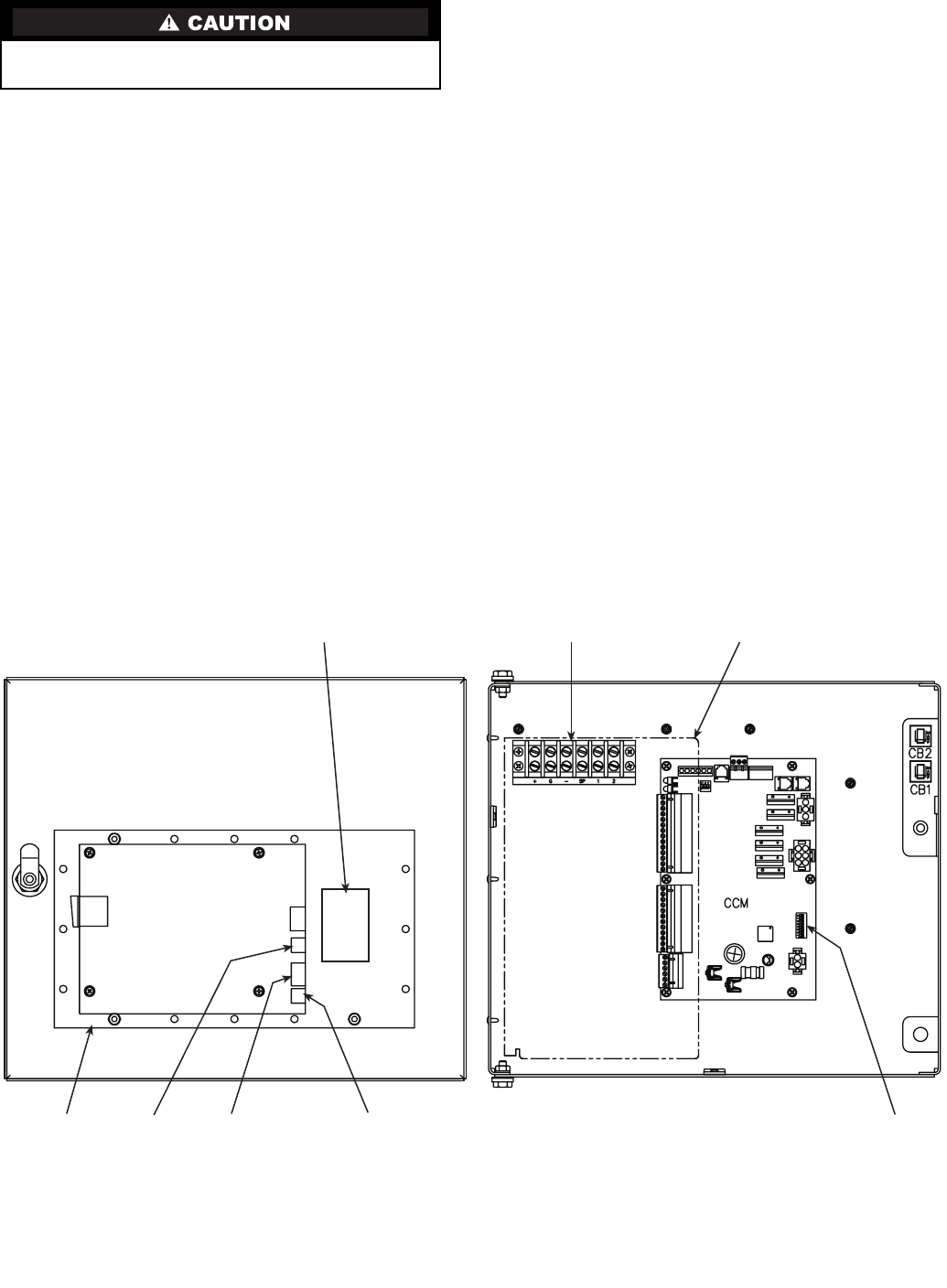
87
Control Modules
The CVC/ICVC, CCM, and ISM modules perform continu-
ous diagnostic evaluations of the hardware to determine its
condition. Proper operation of all modules is indicated by
LEDs (light-emitting diodes) located on the circuit board of the
CVC/ICVC, CCM, and ISM.
There is one green LED located on the CCM and ISM
boards respectively, and one red LED located on the CVC/
ICVC, CCM, and ISM boards respectively.
RED LED (Labeled as STAT) — If the red LED:
•blinks continuously at a 2-second interval, the module is
operating properly
•is lit continuously, there is a problem that requires
replacing the module
•is off continuously, the power should be checked
•blinks 3 times per second, a software error has been dis-
covered and the module must be replaced
If there is no input power, check the fuses and circuit break-
er. If the fuse is good, check for a shorted secondary of the
transformer or, if power is present to the module, replace the
module.
GREED LED (Labeled as COM) — These LEDs indicate
the communication status between different parts of the con-
troller and the network modules and should blink continuously.
Notes on Module Operation
1. The chiller operator monitors and modifies configura-
tions in the microprocessor by using the 4 softkeys and
the CVC/ICVC. Communications between the CVC/
ICVC and the CCM is accomplished through the SIO
(Sensor Input/Output) bus, which is a phone cable. The
communication between the CCM and ISM is accom-
plished through the sensor bus, which is a 3-wire cable.
2. If a green LED is on continuously, check the communica-
tion wiring. If a green LED is off, check the red LED
operation. If the red LED is normal, check the module
address switches (SW1) (Fig. 40 and 41). Confirm all
switches are in OFF position.
All system operating intelligence resides in the CVC/
ICVC. Some safety shutdown logic resides in the ISM in
case communications are lost between the ISM and CVC/
ICVC. Outputs are controlled by the CCM and ISM as
well.
3. Power is supplied to the modules within the control panel
via 24-vac power sources.
The transformers are located within the power panel, with
the exception of the ISM, which operates from a 115-vac
power source and has its own 24-vac transformer located
in the module.
In the power panel, T1 supplies power to the compressor
oil heater, oil pump, and optional hot gas bypass, and T2
supplies power to both the CVC/ICVC and CCM.
Power is connected to Plug J1 on each module.
Turn controller power off before servicing controls. This
ensures safety and prevents damage to the controller.
CCN INTERFACE
CONNECTION
DATALINK OR
DATAPORT MODULE (OPTION)
SW1BACK OF CVC
MODULE PART NUMBER
SOFTWARE PART NUMBER
J7 SIO J1 POWER/
CCN
J8 SERVICE
CVC/ICVC
Fig. 40 — Rear of CVC/ICVC (Chiller Visual Controller/International Chiller Visual Controller)
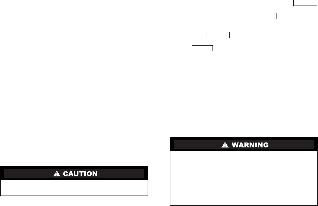
88
Chiller Control Module (CCM) (Fig. 41)
INPUTS — Each input channel has 2 or 3 terminals. Refer to
individual chiller wiring diagrams for the correct terminal
numbers for your application.
OUTPUTS — Output is 24 vac. There are 2 terminals per out-
put. Refer to the chiller wiring diagram for your specific appli-
cation for the correct terminal numbers.
Integrated Starter Module (Fig. 42)
INPUTS — Inputs on strips J3 through J6 are analog inputs
and J2 is discrete (on/off) input. The specific application of the
chiller determines which terminals are used. Refer to the indi-
vidual chiller wiring diagram for the correct terminal numbers
for your application.
OUTPUTS — Outputs are 115-277 vac and wired to strip J9.
There are 2 terminals per output.
Replacing Defective Processor Modules —
The module replacement part number is printed on a small
label on the rear of the CVC/ICVC module. The chiller model
and serial numbers are printed on the chiller nameplate located
on an exterior corner post. The proper software is factory-
installed by Carrier in the replacement module. When ordering
a replacement chiller visual control (CVC/ICVC) module,
specify the complete replacement part number, full chiller
model number, and chiller serial number. The installer must
configure the new module to the original chiller data. Follow
the procedures described in the Software Configuration section
on page 55.
INSTALLATION
1. Verify the existing CVC/ICVC module is defective by us-
ing the procedure described in the Troubleshooting Guide
section, page 76, and the Control Modules section,
page 87. Do not select the ATTACH TO NETWORK
DEVICE table if the CVC/ICVC indicates a communica-
tion failure.
2. Data regarding the CVC/ICVC configuration should have
been recorded and saved. This data must be reconfigured
into the new CVC/ICVC. If this data is not available, fol-
low the procedures described in the Software Configura-
tion section.
If a CCN Building Supervisor or Service Tool is avail-
able, the module configuration should have already been
uploaded into memory. When the new module is in-
stalled, the configuration can be downloaded from the
computer.
Any communication wires from other chillers or CCN
modules should be disconnected to prevent the new
CVC/ICVC module from uploading incorrect run hours
into memory.
3. To install this module, record values for the TOTAL
COMPRESSOR STARTS and the COMPRESSOR
ONTIME from the MAINSTAT screen on the CVC/
ICVC.
4. Power off the controls.
5. Remove the old CVC/ICVC.
6. Install the new CVC/ICVC module. Turn the control
power back on.
7. The CVC/ICVC now automatically attaches to the local
network device.
8. Access the MAINSTAT table and highlight the TOTAL
COMPRESSOR STARTS parameter. Press the
softkey. Increase or decrease the value to match the starts
value recorded in Step 3. Press the softkey
when you reach the correct value. Now, move the high-
light bar to the COMPRESSOR ONTIME parameter.
Press the softkey. Increase or decrease the run
hours value to match the value recorded in Step 2. Press
the softkey when the correct value is reached.
9. Complete the CVC/ICVC installation. Following the in-
structions in the Input Service Configurations section,
page 55, input all the proper configurations such as the
time, date, etc. Check the pressure transducer calibra-
tions. PSIO installation is now complete.
Solid-State Starters — Troubleshooting information per-
taining to the Benshaw, Inc., solid-state starter may be found
in the following paragraphs and in the Carrier RediStart
MICRO™ Instruction Manual supplied by the starter vendor.
Attempt to solve the problem by using the following prelim-
inary checks before consulting the troubleshooting tables found
in the Benshaw manual.
With power off:
•Inspect for physical damage and signs of arcing, over-
heating, etc.
•Verify the wiring to the starter is correct.
•Verify all connections in the starter are tight.
•Check the control transformer fuses.
TESTING SILICON CONTROL RECTIFIERS IN THE
BENSHAW, INC., SOLID-STATE STARTERS — If an SCR
is suspected of being defective, use the following procedure as
part of a general troubleshooting guide.
1. Verify power is applied.
2. Verify the state of each SCR light-emitting diode (LED)
on the micropower card.
NOTE: All LEDs should be lit. If any red or green side of
these LEDs is not lit, the line voltage is not present or one
or more SCRs has failed.
3. Check incoming power. If voltage is not present check
the incoming line. If voltage is present, proceed to Steps 4
through 11.
NOTE: If after completing Steps 4 - 11 all measurements
are within specified limits, the SCRs are functioning nor-
mally. If after completing Steps 4 - 11 resistance measure-
ments are outside the specified limits, the motor leads on
the starter power lugs T1 through T6 should be removed
and the steps repeated. This will identify if abnormal re-
sistance measurements are being influenced by the motor
windings.
4. Remove power from the starter unit.
Electrical shock can cause personal injury. Disconnect all
electrical power before servicing.
1. Motor terminals or starter output lugs or wire should
not be touched without disconnecting the incoming
power supply. The silicon control rectifiers (SCRs)
although technically turned off still have AC mains
potential on the output of the starter.
2. Power is present on all yellow wiring throughout the
system even though the main circuit breaker in the
unit is off.
SELECT
ENTER
SELECT
ENTER
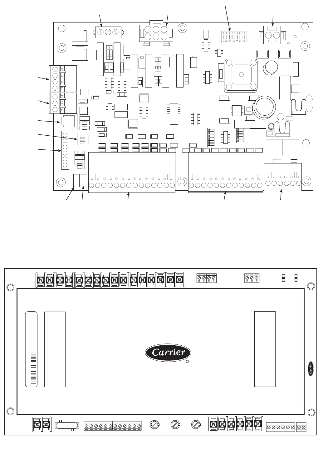
89
STAT COMM THERMISTORS
J4
DIFF PRESSURE
J3
PRESSURE
J2
SW2
V/I INPUTS
J5
SIO
J7
ANALOG OUT
J8
J11
DISCRETE
OUTPUTS
J12
DISCRETE
OUTPUTS
J1
24 VAC
SIO
J6
SW1
115 VAC
LL1 LL2 1A
CONTACT INPUTS
SPAR ICE REM STRT 1M 2M
SFTY BLD STRT FLT AUX AUX
FUSE LINE VOLTAGES
L1 L2 L3 IL1
LINE CURRENTS GROUND
FAULTS
IL2 IL3 1/4 2/5 3/6 VFD
HZ
INTEGRATED STARTER MODULE
INTERGRATED STARTER MODULE
1A
J11 1+ C + C + C + C + C + C
J2
J3-1 J3-2 J3-3
J4
1+ - + - + -
J5
1+ G + G + G + G
1
J6
STAT COM
-J7
- G + 1G + G +
J8
1J9 1
COMM
C B A
4-20 MA OUT
SPARE VFD
TRIP
ALARM HI
FAN
LO
FAN COND
PUMP
EVAP
PUMP
SHUNT
TRIP
DISCRETE CONTROL CONTACTS
TRANS 1CR
R
WARNING
HIGH VOLTAGE
DISCONNECT POWER BEFORE SERVICING
ISM 19XR04012201 9925
CEPL13025901 PCB05
CEPP130173-03-04-01 00001328
WARNING
HIGH VOLTAGE
DISCONNECT POWER BEFORE SERVICING
Fig. 41 — Chiller Control Module (CCM)
Fig. 42 — Integrated Starter Module (ISM)
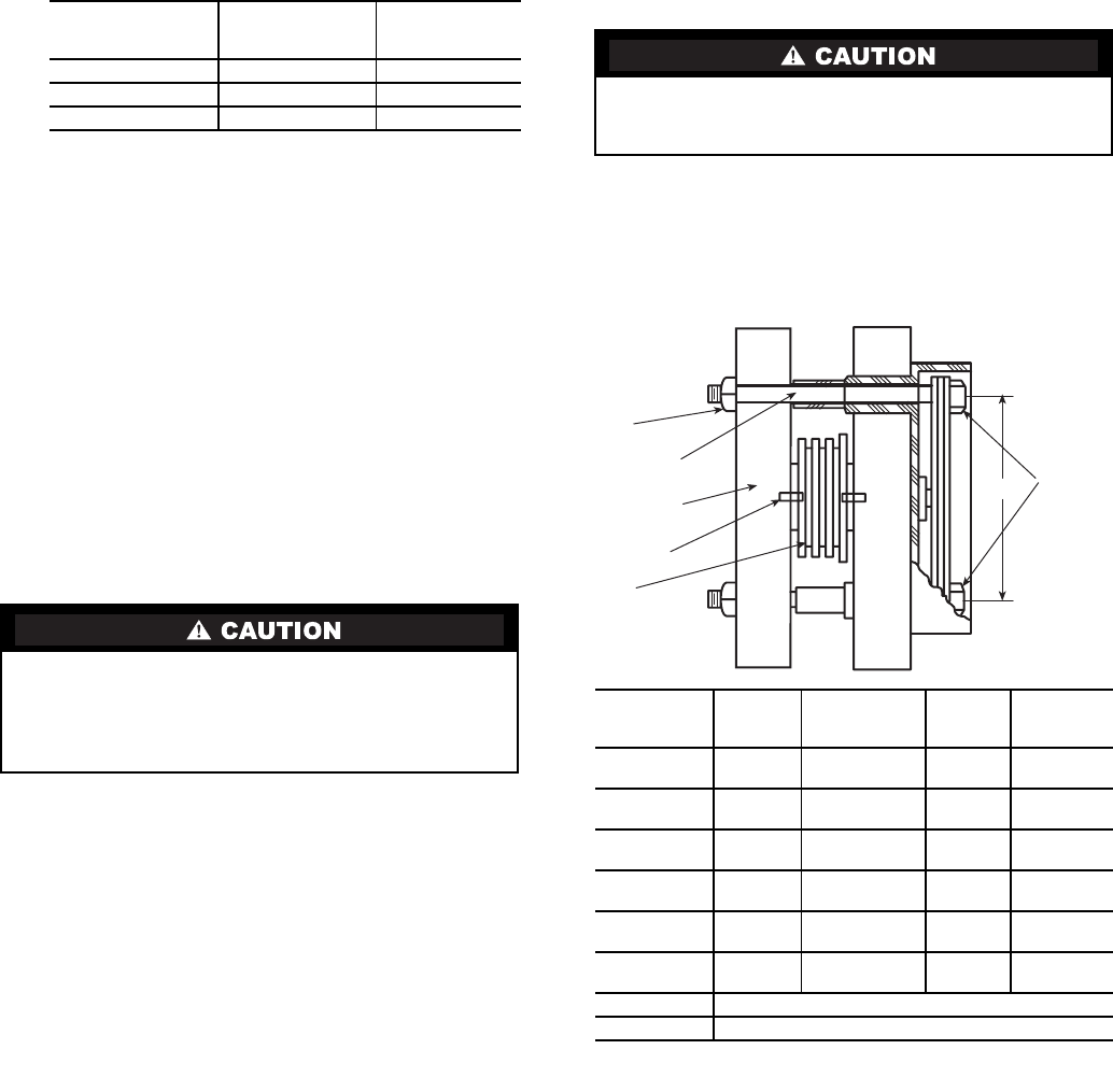
90
5. Using an ohmmeter, perform the following resistance
measurements and record the results:
If all measured values are greater than 5K ohms, proceed
to Step 10. If any values are less than 5K ohms, one or
more of the SCRs in that pair is shorted.
6. Remove both SCRs in the pair (See SCR Removal/
Installation).
7. Using an ohmmeter, measure the resistance (anode to
cathode) of each SCR to determine which device has
failed.
NOTE: Both SCRs may be defective, but typically, only
one is shorted. If both SCRs provide acceptable resistance
measurements, proceed to Step 10.
8. Replace the defective SCR(s).
9. Retest the “pair” for resistance values indicated above.
10. On the right side of the firing card, measure the resistance
between the red and white gate/cathode leads for each
SCR (1 through 6). A measurement between 5 and
50 ohms is normal. Abnormally high values may indicate
a failed gate for that SCR.
11. Replace the SCRs and retest the pair.
SCR REMOVAL/INSTALLATION — Refer to Fig. 43.
1. Remove the SCR by loosening the clamping bolts on
each side of the SCR,
2. After the SCR has been removed and the bus work is
loose, apply a thin coat of either silicon based thermal
joint compound or a joint compound for aluminum or
copper wire connections to the contact surfaces of the re-
placement SCR. This allows for improved heat dissipa-
tion and electrical conductivity.
3. Place the SCR between the roll pins on the heatsink
assemblies so the roll pins fit into the small holes in each
side of the SCR.
NOTE: Ensure the SCR is installed so the cathode side is
the side from which the red wire extends. The heatsink is
labeled to show the correct orientation.
4. Hand tighten the bolts until the SCR contacts the
heatsink.
5. Using quarter-turn increments, alternating between
clamping bolts, apply the appropriate number of whole
turns referencing the table in Fig. 43.
6. Reconnect the red (cathode) wire from the SCR and the
white (anode-gate) wire to the appropriate location on the
firing card (i.e., SCR1 wires to firing card terminal
G1-white wire, and K1-red wire).
7. Reconnect all other wiring and bus work.
8. Return starter to normal operation.
Physical Data — Tables 13A-20 and Fig. 44-57 provide
additional information on component weights, compressor fits
and clearances, physical and electrical data, and wiring sche-
matics for the operator’s convenience during troubleshooting.
MEASURE
BETWEEN
SCR PAIRS
BEING
CHECKED
RECORDED
VALU E
T1 and T6 3 and 6
T2 and T4 2 and 5
T3 and T5 1 and 4
If any red or white SCR gate leads are removed from the
firing card or an SCR, care must be taken to ensure the
leads are replaced EXACTLY as they were (white wires to
gates, and red wires to cathodes on both the firing card and
SCR), or damage to the starter and/or motor may result.
Care must be taken to prevent nut rotation while tightening
the bolts. If the nut rotates while tightening the bolt, SCR
replacement must be started over.
Fig. 43 — SCR Installation
SCR PART
NUMBER
BISCR
CLAMP
SIZE
A
DIMENSION
(in.)
NO. OF
TURNS
BOLT
LENGTH
(in.)
6601218 1030 2.75
(70 mm) 11/23.0
(76 mm)
6601818 1030 2.75
(70 mm) 11/23.0
(76 mm)
8801230 1035 2.75
(70 mm) 13/43.5
(89 mm)
8801830 1035 2.75
(70 mm) 13/43.0
(89 mm)
15001850 2040 4.00
(102 mm) 23/44.0
(102 mm)
15001850 2050 4.00
(102 mm) 23/45.0
(127 mm)
220012100 Consult Benshaw Representative
330018500 Consult Benshaw Representative
LOOSEN
AND
TIGHTEN
BOLTS
FROM
THIS END
CLAMPING
BOLT
NUT
ALUMINUM
HEATSINK
ROLL PIN
SCR
A

91
Table 13A — Heat Exchanger Data (English)
NOTES:
1. Cooler data: based on a cooler with standard wall tubing, 2-pass,
150 psig, nozzle-in-head waterbox with victaulic grooves. Weight
includes suction elbow, control panel, and distribution piping.
Weight does not include compressor.
2. Condenser data: based on a condenser with standard wall tub-
ing, 2-pass, 150 psig, nozzle-in-head waterbox with victaulic
grooves. Weight includes the float valve, discharge elbow, and
distribution piping. Weight does not include unit-mounted starter,
isolation valves, and pumpout unit.
CODE
NUMBER OF TUBES ENGLISH
Dry (Rigging) Weight (lb) Chiller Charge
Cooler Condenser Cooler
Only
Condenser
Only
Refrigerant Weight (lb) Water Volume (gal)
Cooler Condenser Cooler Condenser
10 142 180 2,742 2,704 290 200 34 42
11 161 200 2,812 2,772 310 200 37 45
12 180 225 2,883 2,857 330 200 40 49
15 142 180 3,003 2,984 320 250 39 48
16 161 200 3,089 3,068 340 250 43 52
17 180 225 3,176 3,173 370 250 47 57
20 200 218 3,442 3,523 345 225 48 48
21 240 266 3,590 3,690 385 225 55 55
22 282 315 3,746 3,854 435 225 62 63
30 200 218 4,137 3,694 350 260 55 55
31 240 267 4,319 3,899 420 260 64 65
32 280 315 4,511 4,100 490 260 72 74
35 200 218 4,409 4,606 400 310 61 62
36 240 267 4,617 4,840 480 310 70 72
37 280 315 4,835 5,069 550 310 80 83
40 324 370 5,898 6,054 560 280 89 96
41 364 417 6,080 6,259 630 280 97 106
42 400 463 6,244 6,465 690 280 105 114
45 324 370 6,353 6,617 640 330 98 106
46 364 417 6,561 6,851 720 330 108 117
47 400 463 6,748 7,085 790 330 116 127
50 431 509 7,015 7,285 750 400 115 128
51 485 556 7,262 7,490 840 400 126 137
52 519 602 7,417 7,683 900 400 133 136
5A 225 —6,426 —500 —106 —
5B 241 —6,499 —520 —109 —
5C 258 —6,577 —550 —112 —
55 431 509 7,559 7,980 870 490 127 142
56 485 556 7,839 8,214 940 490 139 152
57 519 602 8,016 8,434 980 490 147 162
5F 225 —6,879 —550 —116 —
5G 241 —6,962 —570 —120 —
5H 258 —7,050 —600 —124 —
60 557 648 8,270 8,286 940 420 144 159
61 599 695 8,462 8,483 980 420 153 168
62 633 741 8,617 8,676 1020 420 160 177
65 557 648 8,943 9,204 1020 510 160 176
66 599 695 9,161 9,428 1060 510 169 187
67 633 741 9,338 9,648 1090 510 177 197
70 644 781 12,395 13,139 1220 780 224 209
71 726 870 12,821 13,568 1340 780 243 229
72 790 956 13,153 13,969 1440 780 257 248
75 644 781 13,293 14,211 1365 925 245 234
76 726 870 13,780 14,702 1505 925 266 257
77 790 956 14,159 15,160 1625 925 283 278
80 829 990 16,156 15,746 1500 720 285 264
81 901 1080 16,530 16,176 1620 720 302 284
82 976 1170 16,919 16,606 1730 720 319 304
85 829 990 17,296 17,001 1690 860 313 295
86 901 1080 17,723 17,492 1820 860 331 318
87 976 1170 18,169 17,984 1940 860 351 341

92
Table 13B — Heat Exchanger Data (SI)
NOTES:
1. Cooler data: based on a cooler with standard wall tubing, 2-pass,
1034 psig, nozzle-in-head waterbox with victaulic grooves.
Weight includes suction elbow, control panel, and distribution pip-
ing. Weight does not include compressor.
2. Condenser data: based on a condenser with standard wall tub-
ing, 2-pass, 1034 kPa, nozzle-in-head waterbox with victaulic
grooves. Weight includes the float valve, discharge elbow, and
distribution piping. Weight does not include unit-mounted starter,
isolation valves, and pumpout unit.
CODE
NUMBER OF TUBES SI
Dry (Rigging) Weight (kg) Chiller Charge
Cooler Condenser Cooler
Only
Condenser
Only
Refrigerant Weight (kg) Water Volume (L)
Cooler Condenser Cooler Condenser
10 142 180 1244 1226 132 91 129 158
11 161 200 1275 1257 141 91 140 170
12 180 225 1307 1296 150 91 152 185
15 142 180 1362 1353 145 113 149 183
16 161 200 1401 1391 154 113 163 198
17 180 225 1440 1439 168 113 178 216
20 200 218 1561 1598 157 102 183 181
21 240 266 1628 1673 175 102 207 210
22 282 315 1699 1748 197 102 234 239
30 200 218 1876 1675 159 118 208 210
31 240 267 1958 1768 190 118 242 246
32 280 315 2046 1859 222 118 271 282
35 200 218 2000 2089 181 141 232 233
36 240 267 2094 2195 218 141 266 273
37 280 315 2193 2300 249 141 301 314
40 324 370 2675 2745 254 127 338 365
41 364 417 2757 2839 286 127 368 400
42 400 463 2832 2932 313 127 396 433
45 324 370 2881 3001 290 150 372 403
46 364 417 2976 3107 327 150 407 442
47 400 463 3060 3213 358 150 438 481
50 431 509 3181 3304 340 181 435 483
51 485 556 3293 3397 381 181 477 518
52 519 602 3364 3484 408 181 502 552
5A 225 —2915 —227 —401 —
5B 241 —2949 —236 —412 —
5C 258 —2984 —250 —424 —
55 431 509 3428 3619 395 222 481 536
56 485 556 3555 3725 426 222 527 575
57 519 602 3635 3825 446 222 557 613
5F 225 —3121 —250 —439 —
5G 241 —3159 —259 —454 —
5H 258 —3199 —273 —464 —
60 557 648 3751 3758 426 190 546 601
61 599 695 3838 3847 444 190 578 636
62 633 741 3908 3935 462 190 604 669
65 557 648 4056 4174 462 231 605 668
66 599 695 4155 4276 481 231 641 707
67 633 741 4235 4376 494 231 671 745
70 644 781 5622 5959 553 354 848 791
71 726 870 5814 6153 608 354 919 867
72 790 956 5965 6335 653 354 974 937
75 644 781 6028 6445 619 420 927 885
76 726 870 6259 6667 683 420 1009 971
77 790 956 6421 6875 737 420 1072 1052
80 829 990 7326 7141 680 327 1080 1000
81 901 1080 7496 7336 735 327 1143 1075
82 976 1170 7673 7531 785 327 1208 1150
85 829 990 7844 7710 766 390 1183 1118
86 901 1080 8037 7933 825 390 1254 1205
87 976 1170 8240 8156 880 390 1329 1291
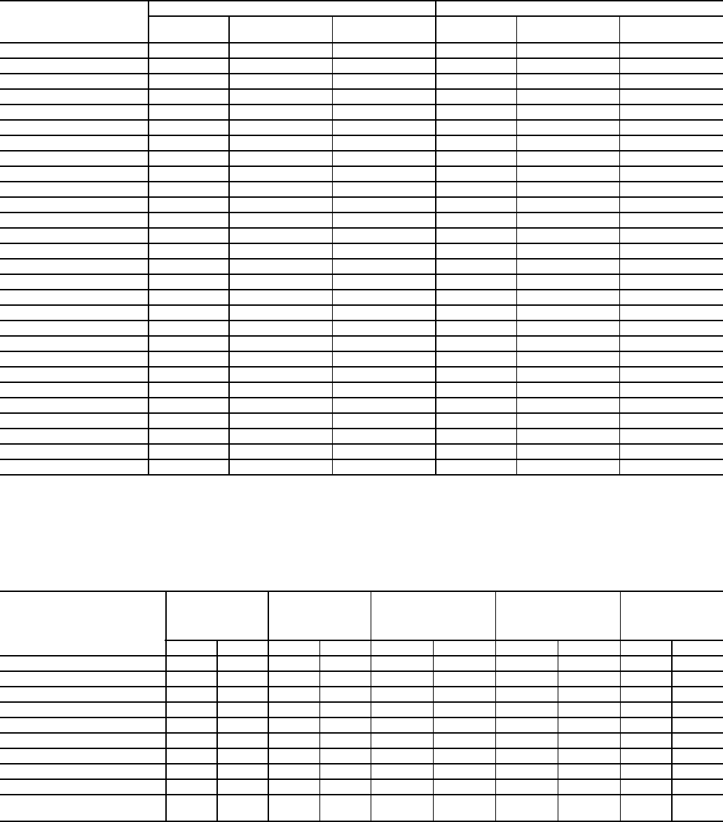
93
Table 14 — 19XR Additional Data for Marine Waterboxes*
*Add to heat exchanger data for total weights or volumes.
NOTES:
1. Weight adder shown is the same for cooler and condenser of equal frame size.
2. For the total weight of a vessel with a marine waterbox, add these values to the heat
exchanger weights (or volumes).
Table 15 — Compressor Weights
*Transmission weight does not include rotor, shaft, and gear.
HEAT EXCHANGER
FRAME, PASS
ENGLISH SI
Psig Rigging Weight
(lb)
Water Volume
(gal) kPa Rigging Weight
(kg)
Water Volume
(L)
FRAME 2, 1 AND 2 PASS 150 730 84 1034 331 318
FRAME 2, 2 PASS 150 365 42 1034 166 159
FRAME 3, 1 AND 2 PASS 150 730 84 1034 331 317
FRAME 3, 2 PASS 150 365 42 1034 166 159
FRAME 4, 1 AND 3 PASS 150 1060 123 1034 481 465
FRAME 4, 2 PASS 150 530 61 1034 240 231
FRAME 5, 1 AND 3 PASS 150 1240 139 1034 562 526
FRAME 5, 2 PASS 150 620 69 1034 281 263
FRAME 6, 1 AND 3 PASS 150 1500 162 1034 680 612
FRAME 6, 2 PASS 150 750 81 1034 340 306
FRAME 7, 1 AND 3 PASS 150 2010 326 1034 912 1234
FRAME 7, 2 PASS 150 740 163 1034 336 617
FRAME 8, 1 AND 3 PASS 150 1855 406 1034 841 1537
FRAME 8, 2 PASS 150 585 203 1034 265 768
FRAME 2, 1 AND 3 PASS 300 860 84 2068 390 318
FRAME 2, 2 PASS 300 430 42 2068 195 159
FRAME 3, 1 AND 3 PASS 300 860 84 2068 390 317
FRAME 3, 2 PASS 300 430 42 2068 195 159
FRAME 4, 1 AND 3 PASS 300 1210 123 2068 549 465
FRAME 4, 2 PASS 300 600 61 2068 272 231
FRAME 5, 1 AND 3 PASS 300 1380 139 2068 626 526
FRAME 5, 2 PASS 300 690 69 2068 313 263
FRAME 6, 1 AND 3 PASS 300 1650 162 2068 748 612
FRAME 6, 2 PASS 300 825 81 2068 374 306
FRAME 7, 1 AND 3 PASS 300 3100 326 2068 1406 1234
FRAME 7, 2 PASS 300 1830 163 2068 830 617
FRAME 8, 1 AND 3 PASS 300 2745 405 2068 1245 1533
FRAME 8, 2 PASS 300 1475 203 2068 766 768
COMPONENT
FRAME 2
COMPRESSOR
WEIGHT
FRAME 3
COMPRESSOR
WEIGHT
FRAME 4
COMPRESSOR
WEIGHT (Without
Split Ring Diffuser)
FRAME 4
COMPRESSOR
WEIGHT (With
Split Ring Diffuser)
FRAME 5
COMPRESSOR
WEIGHT
lb kg lb kg lb kg lb kg lb kg
SUCTION ELBOW 50 23 54 24 175 79 175 79 400 181
DISCHARGE ELBOW 60 27 46 21 157 71 157 71 325 147
TRANSMISSION* 320 145 730 331 656 298 656 298 1000 454
SUCTION HOUSING 300 136 350 159 446 202 810 367 1200 544
IMPELLER SHROUD 35 16 80 36 126 57 200 91 250 113
COMPRESSOR BASE 1260 571 1050 476 1589 721 2022 917 3695 1676
DIFFUSER 35 16 70 32 130 59 130 59 300 136
OIL PUMP 125 57 150 68 150 68 150 68 185 84
MISCELLANEOUS 100 45 135 61 144 65 200 91 220 100
TOTAL WEIGHT
(Less Motor and Elbows) 2300 1043 2660 1207 3712 1684 4548 2063 6850 3107

94
Table 16 — 19XR Motor Weights Standard and High Efficiency Motors
*Stator weight includes stator and shell.
†Rotor weight includes rotor and shaft.
NOTE: When different voltage motors have different weights the largest weight is given.
MOTOR
SIZE
ENGLISH SI
Stator Weight*
(lb)
Rotor Weight†
(lb) End Bell
Cover
(lb)
Stator Weight*
(kg)
Rotor Weight†
(kg) End Bell
Cover
(kg)
60 Hz 50 Hz 60 Hz 50 Hz 60 Hz 50 Hz 60 Hz 50 Hz
BD 1030 1030 240 240 185 467 467 109 109 84
BE 1070 1070 250 250 185 485 485 113 113 84
BF 1120 1120 265 265 185 508 508 120 120 84
BG 1175 1175 290 290 185 533 533 132 132 84
BH 1175 1175 290 290 185 533 533 132 132 84
CD 1286 1358 258 273 274 583 616 117 124 125
CE 1305 1377 265 281 274 592 625 120 127 125
CL 1324 1435 280 296 274 600 651 127 134 125
CM 1347 1455 303 303 274 611 660 137 137 125
CN 1358 1467 316 316 274 616 665 143 143 125
CP 1401 1479 329 316 274 635 671 149 143 125
CQ 1455 1479 329 316 274 660 671 149 152 125
DB 1665 1725 361 391 236 755 782 164 177 107
DC 1681 1737 391 404 236 762 788 177 183 107
DD 1977 2069 536 596 318 897 938 243 248 144
DE 2018 2089 550 550 318 915 948 249 248 144
DF 2100 2139 575 567 318 952 970 261 257 144
DG 2187 2153 599 599 318 992 977 272 272 144
DH 2203 2207 604 604 318 999 1001 274 274 144
DJ 2228 2305 614 614 318 1011 1046 279 279 144
EH 3060 3120 701 751 414 1388 1415 318 341 188
EJ 3105 3250 716 751 414 1408 1474 325 341 188
EK 3180 3250 716 768 414 1442 1474 325 348 188
EL 3180 3370 737 801 414 1442 1529 334 363 188
EM 3270 3370 737 801 414 1483 1529 334 363 188
EN 3270 3520 801 851 414 1483 1597 363 386 188
EP 3340 3520 830 851 414 1515 1597 376 386 188
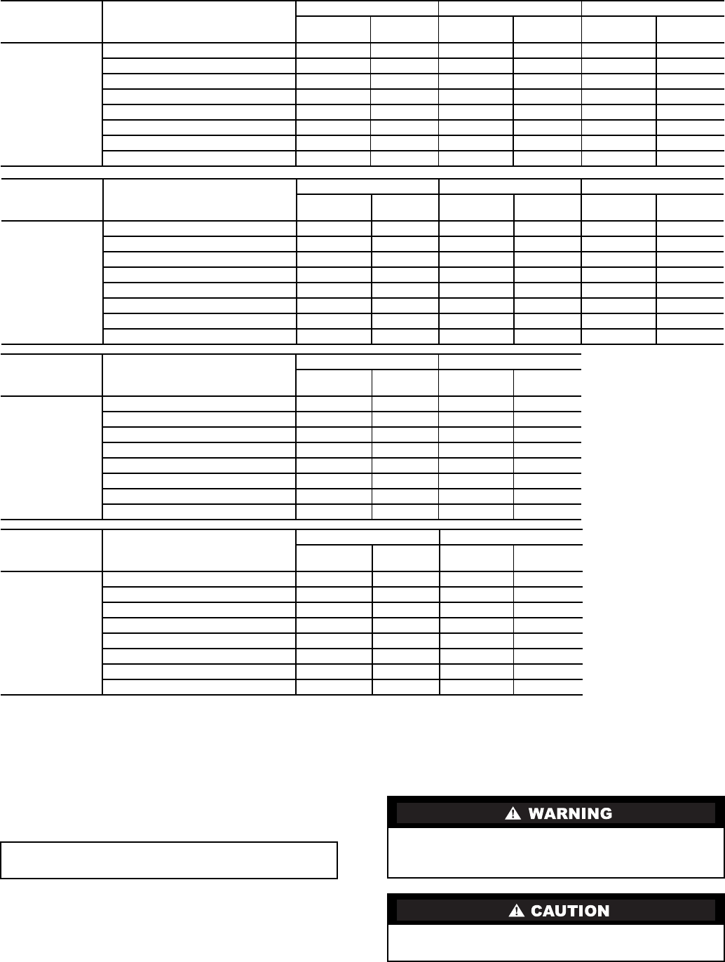
95
Table 17A — 19XR Waterbox Cover Weights — English (lb)
LEGEND
NOTE: Weight for NIH 2-Pass Cover, 150 psig is included in the heat exchanger weights shown in Table 6.
RIG MACHINE COMPONENTS — Refer to instructions
below, Fig. 6-9, and Carrier Certified Prints for machine com-
ponent disassembly.
HEAT
EXCHANGER
WATERBOX
DESCRIPTION
FRAME 1 FRAME 2 FRAME 3
Standard
Nozzles Flanged Standard
Nozzles Flanged Standard
Nozzles Flanged
COOLER/
CONDENSER
NIH, 1 Pass Cover, 150 psig 177 204 320 350 320 350
NIH, 2 Pass Cover, 150 psig 185 218 320 350 320 350
NIH, 3 Pass Cover, 150 psig 180 196 300 340 300 340
NIH/MWB End Cover, 150 psig 136 136 300 300 300 300
NIH, 1 Pass Cover, 300 psig 248 301 411 486 411 486
NIH, 2 Pass Cover, 300 psig 255 324 411 518 411 518
NIH, 3 Pass Cover, 300 psig 253 288 433 468 433 468
NIH/MWB End Cover, 300 psig 175 175 400 400 400 400
HEAT
EXCHANGER
WATERBOX
DESCRIPTION
FRAME 4 FRAME 5 FRAME 6
Standard
Nozzles Flanged Standard
Nozzles Flanged Standard
Nozzles Flanged
COOLER/
CONDENSER
NIH, 1 Pass Cover, 150 psig 148 185 168 229 187 223
NIH, 2 Pass Cover, 150 psig 202 256 224 298 257 330
NIH, 3 Pass Cover, 150 psig 473 489 629 655 817 843
NIH/MWB End Cover, 150 psig 317 317 393 393 503 503
NIH, 1 Pass Cover, 300 psig 593 668 764 839 959 1035
NIH, 2 Pass Cover, 300 psig 594 700 761 878 923 1074
NIH, 3 Pass Cover, 300 psig 621 656 795 838 980 1031
NIH/MWB End Cover, 300 psig 569 569 713 713 913 913
HEAT
EXCHANGER
WATERBOX
DESCRIPTION
FRAME 7 COOLER FRAME 7 CONDENSER
Standard
Nozzles Flanged Standard
Nozzles Flanged
COOLER/
CONDENSER
NIH, 1 Pass Cover, 150 psig 329 441 329 441
NIH, 2 Pass Cover, 150 psig 426 541 426 541
NIH, 3 Pass Cover, 150 psig 1202 1239 1113 1171
NIH/MWB End Cover, 150 psig 789 789 703 703
NIH, 1 Pass Cover, 300 psig 1636 1801 1472 1633
NIH, 2 Pass Cover, 300 psig 1585 1825 1410 1644
NIH, 3 Pass Cover, 300 psig 1660 1741 1496 1613
NIH/MWB End Cover, 300 psig 1451 1451 1440 1440
HEAT
EXCHANGER
WATERBOX
DESCRIPTION
FRAME 8 COOLER FRAME 8 CONDENSER
Standard
Nozzles Flanged Standard
Nozzles Flanged
COOLER/
CONDENSER
NIH, 1 Pass Cover, 150 psig 417 494 417 494
NIH, 2 Pass Cover, 150 psig 531 685 531 685
NIH, 3 Pass Cover, 150 psig 1568 1626 1438 1497
NIH/MWB End Cover, 150 psig 1339 1339 898 898
NIH, 1 Pass Cover, 300 psig 2265 2429 1860 2015
NIH, 2 Pass Cover, 300 psig 2170 2499 1735 2044
NIH, 3 Pass Cover, 300 psig 2273 2436 1883 1995
NIH/MWB End Cover, 300 psig 1923 1923 1635 1635
NIH —Nozzle-in-Head
MWB —Marine Waterbox
IMPORTANT: Only a qualified service technician should
perform this operation.
Do not attempt to disconnect flanges while the machine is
under pressure. Failure to relieve pressure can result in per-
sonal injury or damage to the unit.
Before rigging the compressor, disconnect all wires enter-
ing the power panel.

96
Table 17B — 19XR Waterbox Cover Weights — SI (kg)
LEGEND
NOTE: Weight for NIH 2-Pass Cover, 150 psig is included in the heat exchanger weights shown in Table 6.
HEAT
EXCHANGER
WATERBOX
DESCRIPTION
FRAME 1 FRAME 2 FRAME 3
Standard
Nozzles Flanged Standard
Nozzles Flanged Standard
Nozzles Flanged
COOLER/
CONDENSER
NIH, 1 Pass Cover, 150 psig 80 93 145 159 145 159
NIH, 2 Pass Cover, 150 psig 84 99 145 159 145 159
NIH, 3 Pass Cover, 150 psig 82 89 136 154 140 154
NIH/MWB End Cover, 150 psig 62 62 136 136 136 136
NIH, 1 Pass Cover, 300 psig 112 137 186 220 186 220
NIH, 2 Pass Cover, 300 psig 116 147 186 235 186 235
NIH, 3 Pass Cover, 300 psig 115 131 196 212 196 212
NIH/MWB End Cover, 300 psig 79 79 181 181 181 181
HEAT
EXCHANGER
WATERBOX
DESCRIPTION
FRAME 4 FRAME 5 FRAME 6
Standard
Nozzles Flanged Standard
Nozzles Flanged Standard
Nozzles Flanged
COOLER/
CONDENSER
NIH, 1 Pass Cover, 150 psig 67 84 76 104 85 101
NIH, 2 Pass Cover, 150 psig 92 116 107 135 117 150
NIH, 3 Pass Cover, 150 psig 214 222 285 297 371 382
NIH/MWB End Cover, 150 psig 144 144 178 178 228 228
NIH, 1 Pass Cover, 300 psig 269 303 347 381 435 470
NIH, 2 Pass Cover, 300 psig 269 317 345 398 419 487
NIH, 3 Pass Cover, 300 psig 282 298 361 380 445 468
NIH/MWB End Cover, 300 psig 258 258 323 323 414 414
HEAT
EXCHANGER
WATERBOX
DESCRIPTION
FRAME 7 COOLER FRAME 7 CONDENSER
Standard
Nozzles Flanged Standard
Nozzles Flanged
COOLER/
CONDENSER
NIH, 1 Pass Cover, 150 psig 149 200 149 200
NIH, 2 Pass Cover, 150 psig 193 245 193 245
NIH, 3 Pass Cover, 150 psig 545 562 505 531
NIH/MWB End Cover, 150 psig 357 358 319 319
NIH, 1 Pass Cover, 300 psig 742 817 668 741
NIH, 2 Pass Cover, 300 psig 719 828 640 746
NIH, 3 Pass Cover, 300 psig 753 790 679 732
NIH/MWB End Cover, 300 psig 658 658 653 653
HEAT
EXCHANGER
WATERBOX
DESCRIPTION
FRAME 8 COOLER FRAME 8 CONDENSER
Standard
Nozzles Flanged Standard
Nozzles Flanged
COOLER/
CONDENSER
NIH, 1 Pass Cover, 150 psig 189 224 189 224
NIH, 2 Pass Cover, 150 psig 241 311 241 311
NIH, 3 Pass Cover, 150 psig 711 738 652 679
NIH/MWB End Cover, 150 psig 607 607 407 407
NIH, 1 Pass Cover, 300 psig 1027 1102 844 914
NIH, 2 Pass Cover, 300 psig 984 1134 787 927
NIH, 3 Pass Cover, 300 psig 1031 1105 854 905
NIH/MWB End Cover, 300 psig 872 872 742 742
NIH —Nozzle-in-Head
MWB —Marine Waterbox

97
Table 18 — Optional Pumpout System
Electrical Data
LEGEND
Table 19 — Additional Miscellaneous Weights
VFD — Variable Frequency Drive
Table 20 — Motor Voltage Code
MOTOR
CODE
CONDENSER
UNIT VOLTS-PH-Hz MAX
RLA LRA
119EA47-748 575-3-60 3.8 23.0
419EA42-748 200/208-3-60 10.9 63.5
519EA44-748 230-3-60 9.5 57.5
619EA46-748 400/460-3-50/60 4.7 28.8
LRA —Locked Rotor Amps
RLA —Rated Load Amps
ITEM Lb Kg
CONTROL CABINET 30 14
UNIT-MOUNTED STARTER 500 227
OPTIONAL ISOLATION VALVES 115 52
UNIT MOUNTED VFD 1000 454
MOTOR VOLTAGE CODE
Code Volts Frequency
60 200 60
61 230 60
62 380 60
63 416 60
64 460 60
65 575 60
66 2400 60
67 3300 60
68 4160 60
69 6900 60
50 230 50
51 346 50
52 400 50
53 3000 50
54 3300 50
55 6300 50
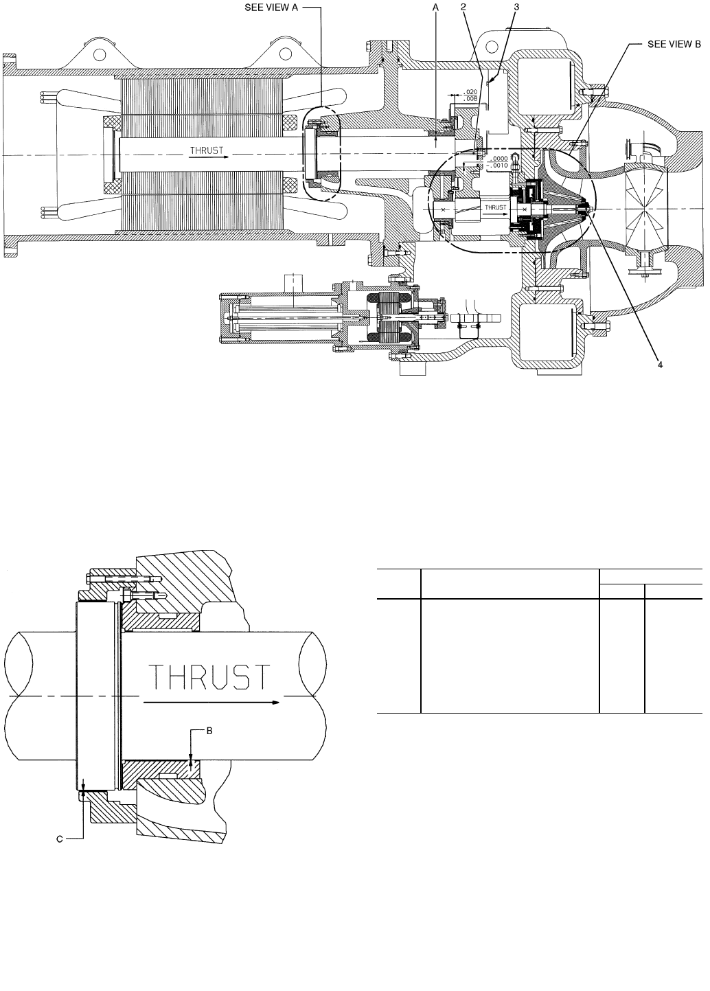
98
Compressor Assembly Torques
LEGEND
*Not shown.
NOTES:
1. All clearances for cylindrical surfaces are diametrical.
2. Dimensions are with rotor in thrust position.
3. Dimensions shown are in inches.
4. Impeller spacing should be performed in accordance with most
recent Carrier Service Bulletin on impeller spacing.
ITEM DESCRIPTION TORQUE
ft.-lb N•m
1* Oil Heater Retaining Nut 20 28
2Bull Gear Retaining Bolt 80-85 108-115
3Demister Bolts 15-19 20-26
4Impeller Retaining Bolt 44-46 60-62
5* Motor Terminals (Low Voltage) 50 68
6* Guide Vane Shaft Seal Nut 25 34
7* Motor Terminals (High Voltage)
— Insulator 2-4 2.7-5.4
— Packing Nut 5 6.8
— Brass Jam Nut 10 13.6
N•m—Newton meters
VIEW A
LOW SPEED SHAFT THRUST DISK
Fig. 44 — Compressor Fits and Clearances
COMPRESSOR, TRANSMISSION AREA
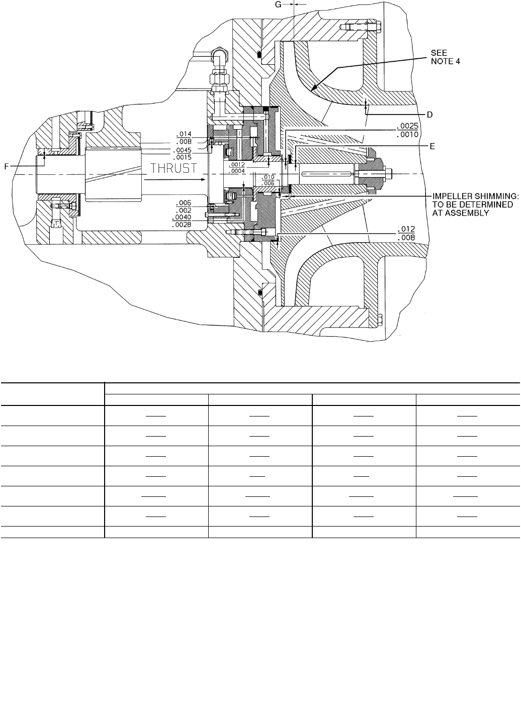
99
VIEW B — HIGH SPEED SHAFT
19XR COMPRESSOR CLEARANCES
*Depends on impeller size, contact your Carrier Service Representative for more information.
NOTE: All clearances for cylindrical surfaces are diametrical.
Fig. 44 — Compressor Fits and Clearances (cont)
ITEM COMPRESSOR CODE
221-299 321-389 421-489 521-599
A.0050
.0040
.0050
.0040
.0055
.0043
.0069
.0059
B.0050
.0040
.0050
.0040
.0053
.0043
.0065
.0055
C.0115
.0055
.0115
.0080
.0100
.0050
.0010
.0060
D.0190
.0040
.022
.012
.027
.017
.0350
.0250
E–.002
–.0005
–.0020
–.0005
–.0029
–.0014
–.0019
–.0005
F.0050
.0040
.0050
.0040
.0048
.0038
.0062
.0052
G—*—*—*—*
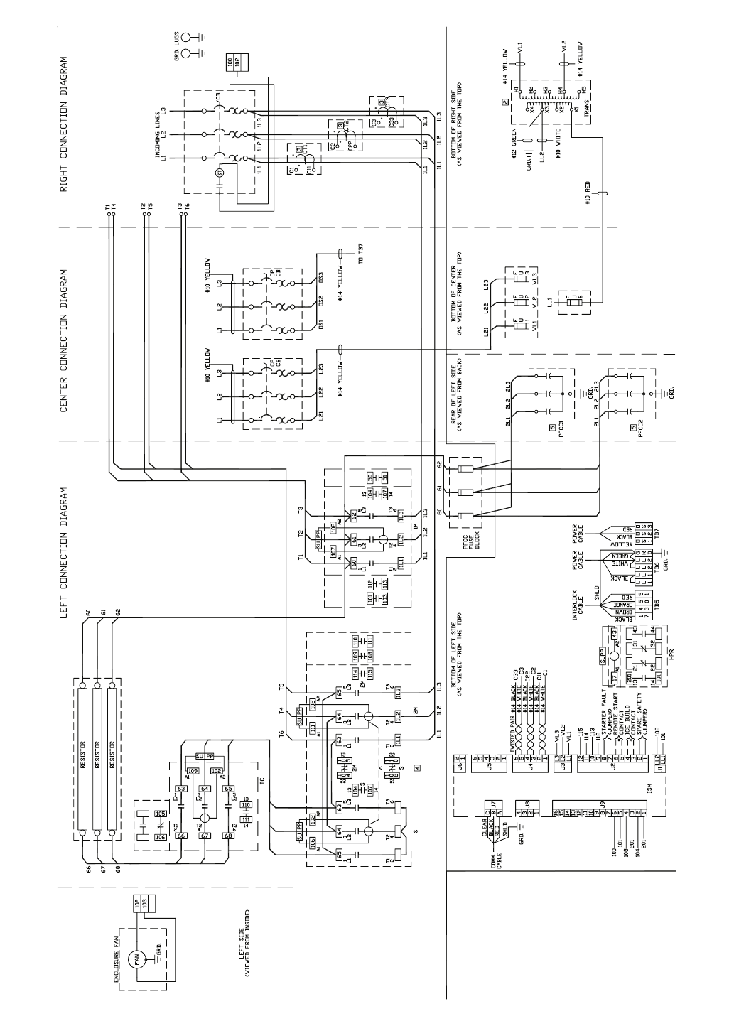
100
Fig. 45 — Allen-Bradley Wye-Delta Unit-Mounted Starter
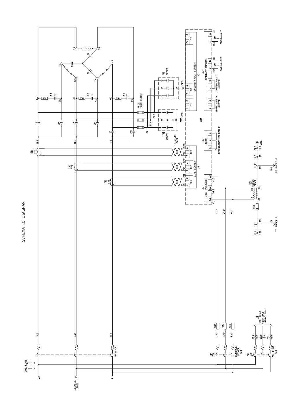
101
Fig. 45 — Allen-Bradley Wye-Delta Unit-Mounted Starter (cont)
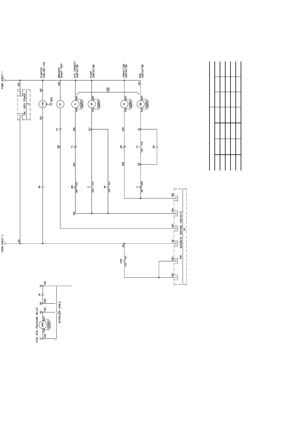
102
Fig. 45 — Allen-Bradley Wye-Delta Unit-Mounted Starter (cont)
C—Contactor
CB —Circuit Breaker
CP —Control Power
CT —Current Transformer
DS —Disconnect Switch
FU —Fuse
GRD —Ground
HPR —High Pressure Relay
ISM —Integrated Starter Module
L—Main Supply Power
LL —Control Power Supply
M—Contactor
OP —Oil Pump
PFCC —Power Factor Correction Capacitor
RES —Resistor
S—Contactor
ST —Shunt Trip
TB —Terminal Block
TC —Transition Contactor
VL —Wire Label
LEGEND NOTES:
1. Remote device.
2. Transformer connected for 480 v primary 120 v secondary. For other
voltages see chart:
3. Current transformer
•amps nameplate ratio
•amps effective ratio with primary turns
•polarity marking
Be sure to connect per polarity markings.
4. “S” - “2M” contactors are electrically and mechanically interlocked.
5. Live capacitor unit. Deenergize starter. Wait one (1) minute and ground
terminals before servicing.
6. All control wiring 14 gage red except as noted.
PRIMARY SECONDARY
H1-H2 H1-H3 H1-H4 H1-H5 X1-X2 X1-X3 X1-X4
240 416 480 600 99 120 130
230 400 460 575 95 115 125
220 380 440 550 91 110 120
208 500 85 100 110
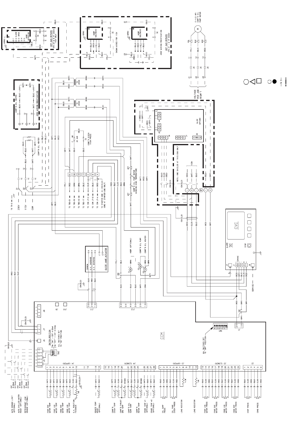
103
LEGEND
AUX —Auxiliary
BRG —Bearing
C—Contactor
CB —Circuit Breaker
CCM —Chiller Control Module
CCN —Carrier Comfort Network
COMP’R—Compressor
COND —Condenser
CVC —Chiller Visual Controller
DISCH —Discharge
DL/DP —Datalink or Dataport
ENT —Entering
EVAP —Evaporator
EXT —External
FR —Frame
GND —Ground
G.V. —Guide Vane
HGBP —Hot Gas Bypass
HT EXCH —Heat Exchanger
LEGEND (cont)
ISM —Integrated Starter Module
L—Main Supply Power
LVG —Leaving
N.O. —Normally Open
PRESS —Pressure
REQM’T—Requirement
TEMP —Temperature
TB —Terminal Board
Denotes Control Panel Terminal
Denotes Oil Pump Terminal
Denotes Power Panel Terminal
** Denotes Motor Starter Panel Conn.
Denotes Component Terminal
Wire Splice
Denotes Conductor
Male/Female Connector
Option Wiring
Fig. 46A — Electronic PIC II Control Panel Wiring Schematic For CVC (Frame 2, 3, 4 Compressor)
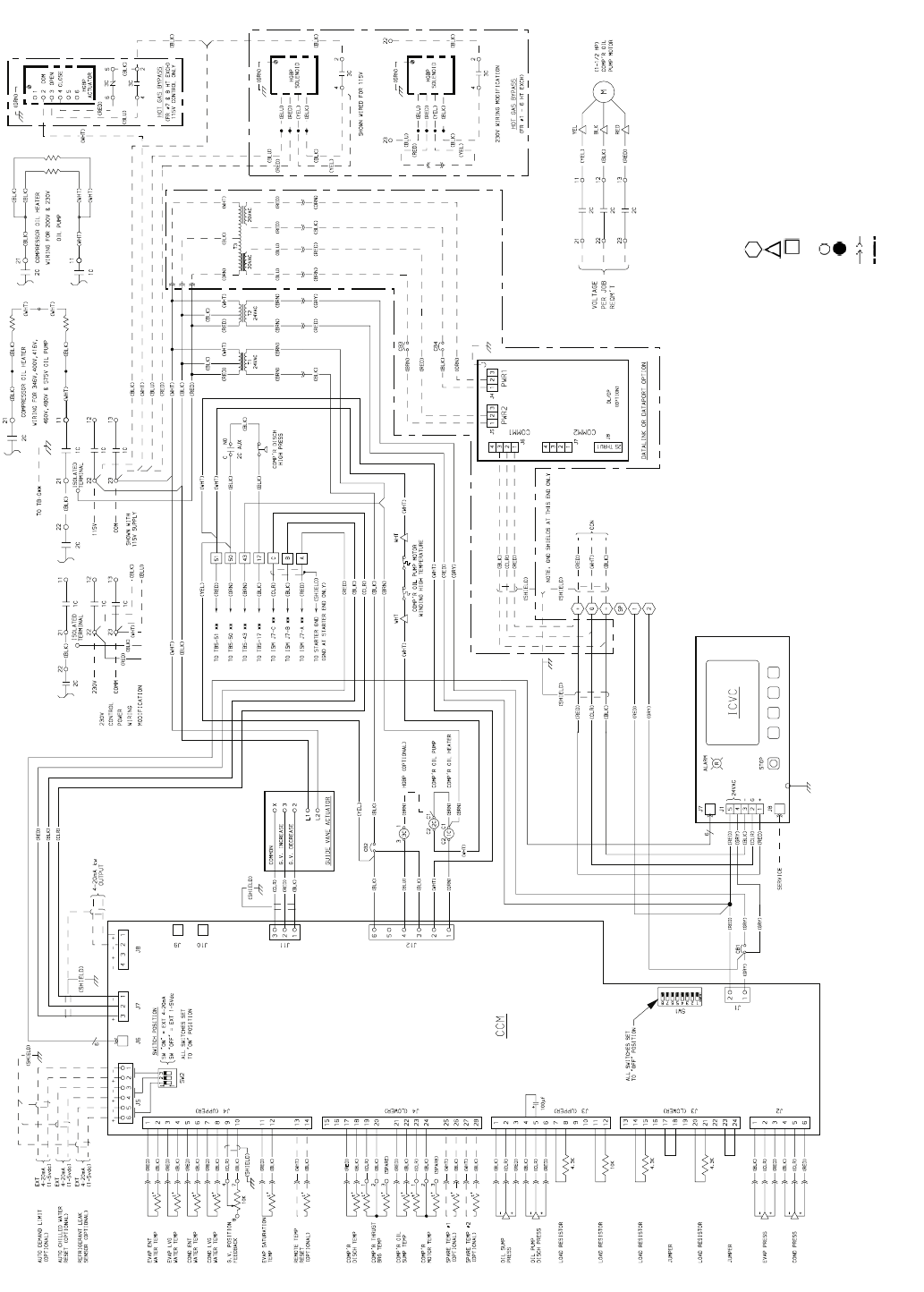
104
LEGEND
AUX —Auxiliary
BRG —Bearing
C—Contactor
CB —Circuit Breaker
CCM —Chiller Control Module
CCN —Carrier Comfort Network
COMP’R—Compressor
COND —Condenser
DISCH —Discharge
DL/DP —Datalink or Dataport
ENT —Entering
EVAP —Evaporator
EXT —External
FR —Frame
GND —Ground
G.V. —Guide Vane
HGBP —Hot Gas Bypass
HT EXCH —Heat Exchanger
ICVC —International Chiller Visual Controller
LEGEND (cont)
ISM —Integrated Starter Module
L—Main Supply Power
LVG —Leaving
N.O. —Normally Open
PRESS —Pressure
REQM’T—Requirement
TEMP —Temperature
TB —Terminal Board
Denotes Control Panel Terminal
Denotes Oil Pump Terminal
Denotes Power Panel Terminal
** Denotes Motor Starter Panel Conn.
Denotes Component Terminal
Wire Splice
Denotes Conductor
Male/Female Connector
Option Wiring
Fig. 46B — Electronic PIC II Control Panel Wiring Schematic For ICVC (Frame 2, 3, 4 Compressor)
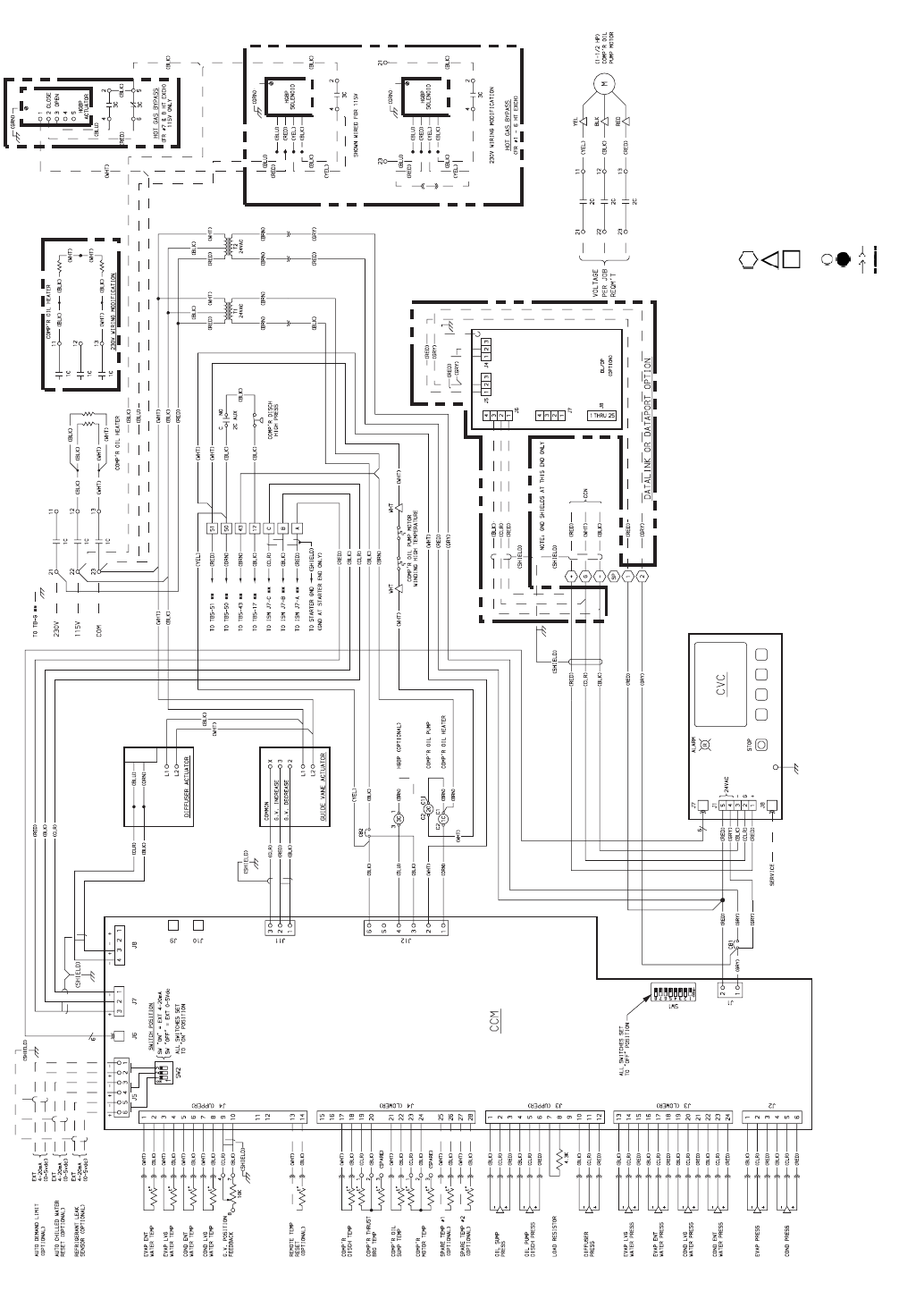
105
LEGEND
AUX —Auxiliary
BRG —Bearing
C—Contactor
CB —Circuit Breaker
CCM —Chiller Control Module
CCN —Carrier Comfort Network
COMP’R—Compressor
COND —Condenser
CVC —Chiller Visual Controller
DISCH —Discharge
DL/DP —Datalink or Dataport
ENT —Entering
EVAP —Evaporator
EXT —External
FR —Frame
GND —Ground
G.V. —Guide Vane
HGBP —Hot Gas Bypass
HT EXCH —Heat Exchanger
LEGEND (cont)
ISM —Integrated Starter Module
L—Main Supply Power
LVG —Leaving
N.O. —Normally Open
PRESS —Pressure
REQM’T—Requirement
TEMP —Temperature
TB —Te r m i n a l B o a r d
Denotes Control Panel Terminal
Denotes Oil Pump Terminal
Denotes Power Panel Terminal
** Denotes Motor Starter Panel Conn.
Denotes Component Terminal
Wire Splice
Denotes Conductor Male/Female Connector
Option Wiring
Fig. 47A — Electronic PIC II Control Panel Wiring Schematic For CVC (Frame 4 with Split Ring Diffuser and Frame 5 Compressor)
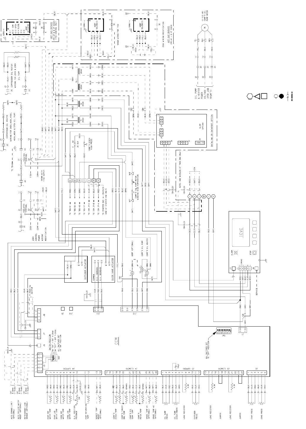
106
LEGEND
AUX —Auxiliary
BRG —Bearing
C—Contactor
CB —Circuit Breaker
CCM —Chiller Control Module
CCN —Carrier Comfort Network
COMP’R—Compressor
COND —Condenser
DISCH —Discharge
DL/DP —Datalink or Dataport
ENT —Entering
EVAP —Evaporator
EXT —External
FR —Frame
GND —Ground
G.V. —Guide Vane
HGBP —Hot Gas Bypass
HT EXCH —Heat Exchanger
ICVC —International Chiller Visual Controller
ISM —Integrated Starter Module
LEGEND (cont)
L—Main Supply Power
LVG —Leaving
N.O. —Normally Open
PRESS —Pressure
REQM’T—Requirement
TEMP —Temperature
TB —Terminal Board
Denotes Control Panel Terminal
Denotes Oil Pump Terminal
Denotes Power Panel Terminal
** Denotes Motor Starter Panel Conn.
Denotes Component Terminal
Wire Splice
Denotes Conductor Male/Female Connector
Option Wiring
Fig. 47B — Electronic PIC II Control Panel Wiring Schematic For ICVC (Frame 4 with Split Ring Diffuser and Frame 5 Compressor)
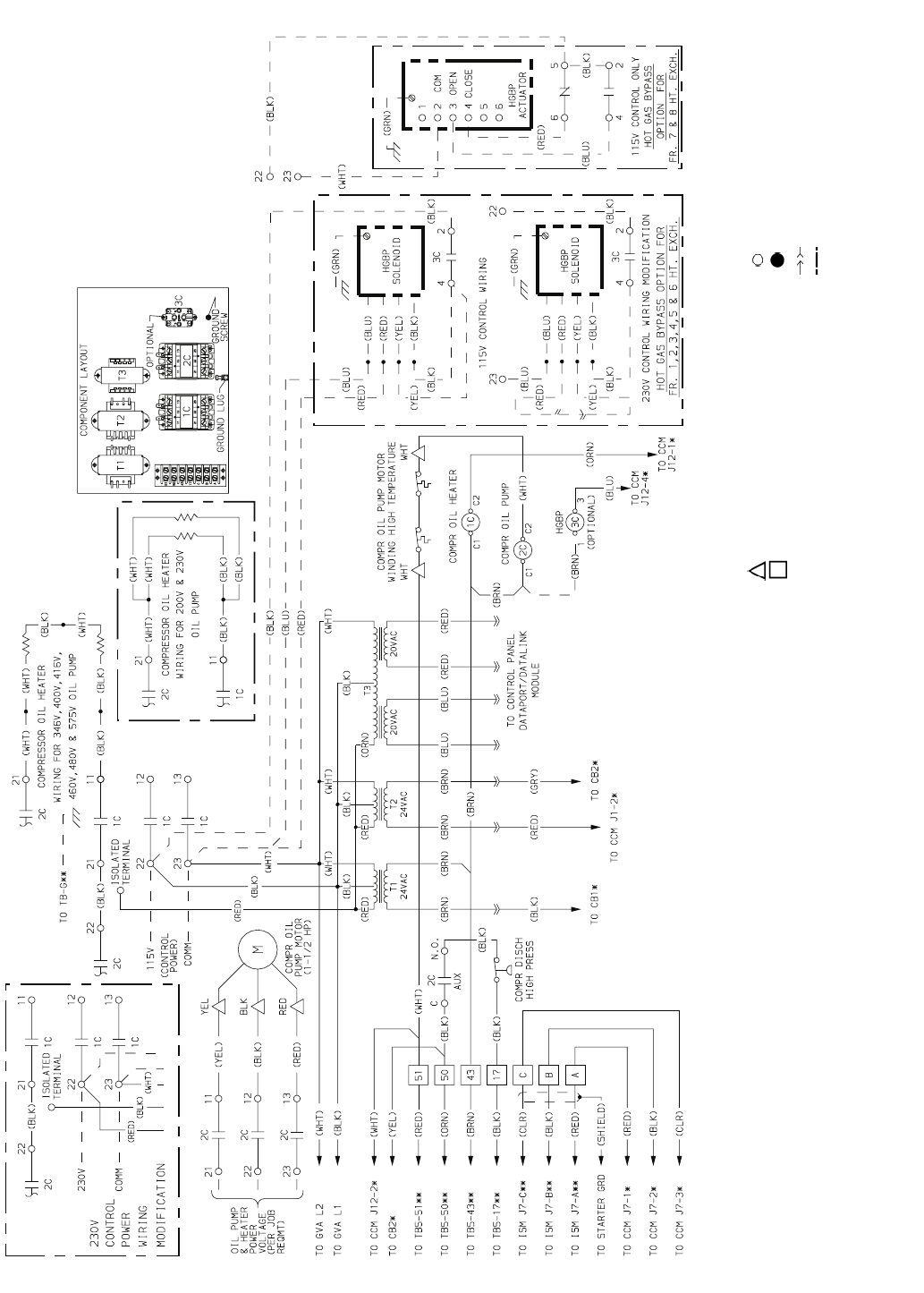
107
AUX —Auxiliary
C—Contactor
CB —Circuit Breaker
CCM —Chiller Control Module
COMM —Communication
COMPR —Compressor
DISCH —Discharge
Denotes Oil Pump Terminal
Denotes Power Panel Terminal
*Denotes Mach. Control Panel Conn.
** Denotes Motor Starter Panel Conn.
Fig. 48 — Power Panel Wiring Schematic
FR —Frame
G—Ground
GRD —Ground
GVA —Guide Vane Actuator
HGBP —Hot Gas Bypass
HT EXCH —Heat Exchanger
ISM —Integrated Starter Module
L—Main Supply Power
N.O. —Normally Open
PRESS —Pressure
REQM’T—Requirement
T—Transformer
TB —Terminal Board
Denotes Component Terminal
Wire Splice
Denotes Conductor Male/Female Connector
Option Wiring
LEGEND
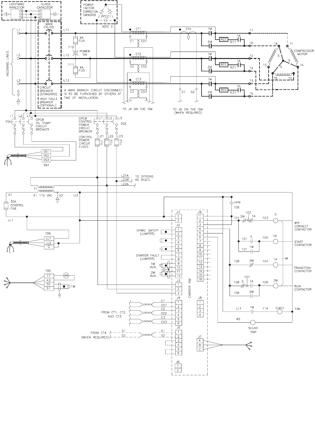
108
AUX —Auxiliary
C—Contactor
CB —Circuit Breaker
CT —Current Transformer
DS —Disconnect Switch
FU —Fuse
G—Ground
Fig. 49 — Cutler-Hammer Wye Delta Unit Mounted Starter Sizes 3-5DP
HPR —High Pressure Relay
ISM —Integrated Starter Module
L—Main Supply Power
LL —Control Power Supply
M—Contactor
RES —Resistor
S—Contactor
TB —Te r m i n a l B l ock
LEGEND NOTES:
1. Power factor correction capacitors (when required) are connected ahead of all current
transformers for proper calibration and sensing by the ISM and IQDP4130.
2. For phase to phase ground fault protection refer to Fig. 51.
3. For metering information refer to Fig. 52.
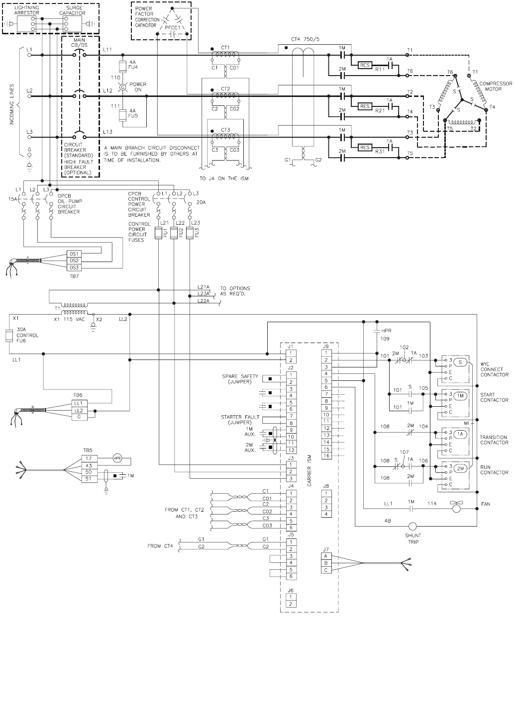
109
AUX —Auxiliary
C—Contactor
CB —Circuit Breaker
CT —Current Transformer
DS —Disconnect Switch
FU —Fuse
G—Ground
Fig. 50 — Cutler-Hammer Wye Delta Unit Mounted Starter Size 6DP
HPR —High Pressure Relay
ISM —Integrated Starter Module
L—Main Supply Power
LL —Control Power Supply
M—Contactor
RES —Resistor
S—Contactor
TB —Te r m i n a l B l ock
LEGEND NOTES:
1. Power factor correction capacitors (when required) are connected ahead of all current
transformers for proper calibration and sensing by the ISM and IQDP4130.
2. For metering option see Fig. 52.
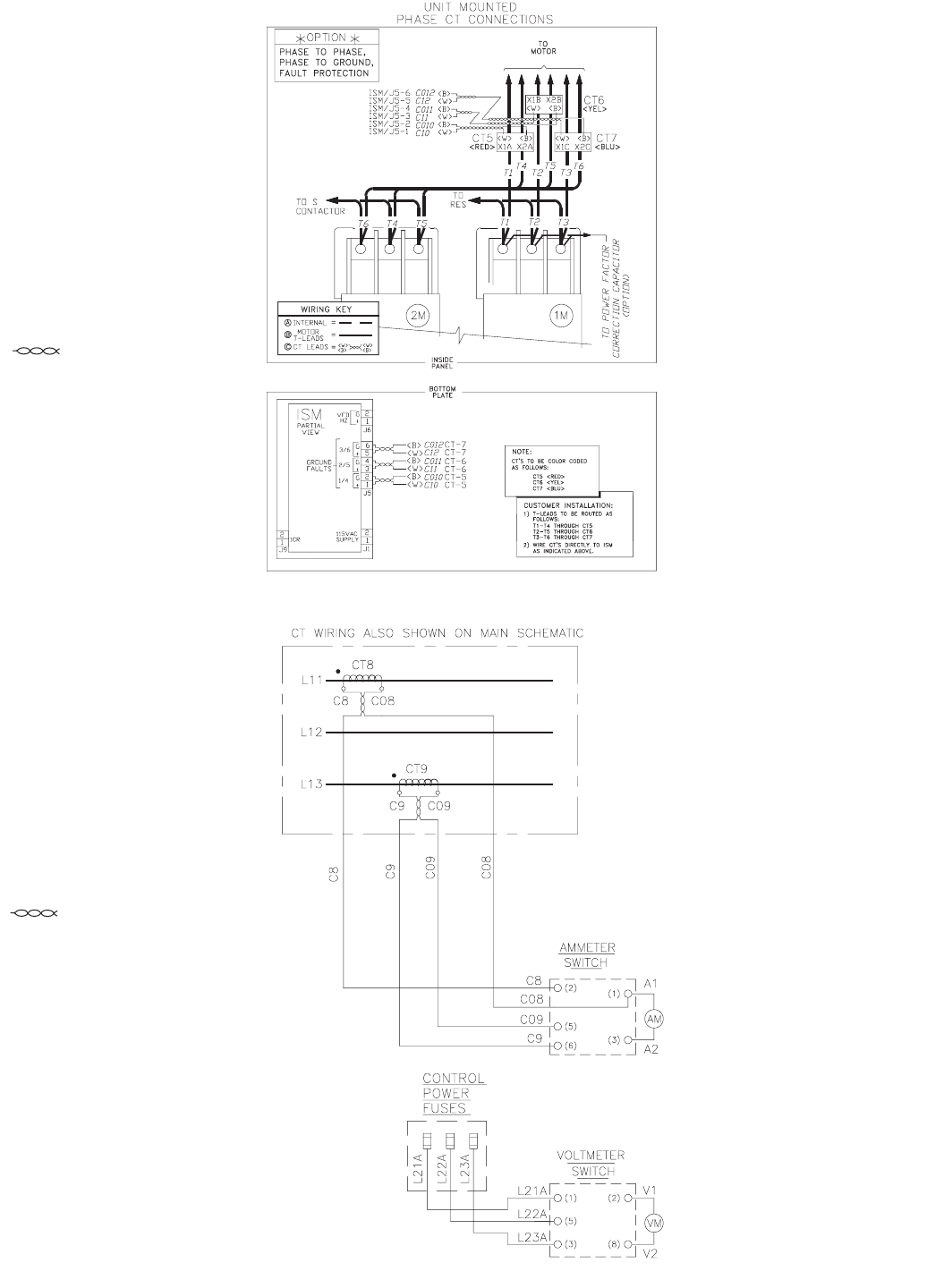
110
Fig. 51 — Ground Fault Phase Current Option
Fig. 52 — Separate Metering Option
LEGEND
AM —Ammeter
CT —Current Transformer
L—Main Power Supply
VM —Voltmeter
Represents Twisted Wire
To Door
LEGEND
CT —Current Transformer
ISM —Integrated Starter Module
VFD —Variable Frequency Drive
Represents Twisted Wire
To Door
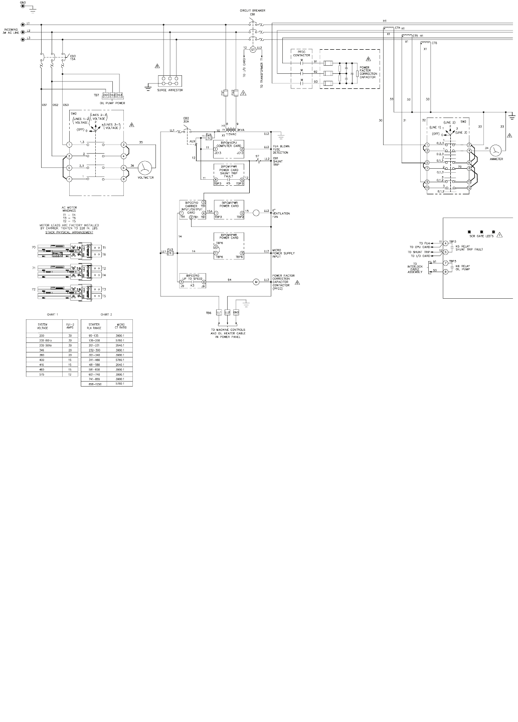
111
Fig. 53 — Benshaw, Inc. Solid-State Unit Mounted Starter Wiring Schematic (Low Voltage)
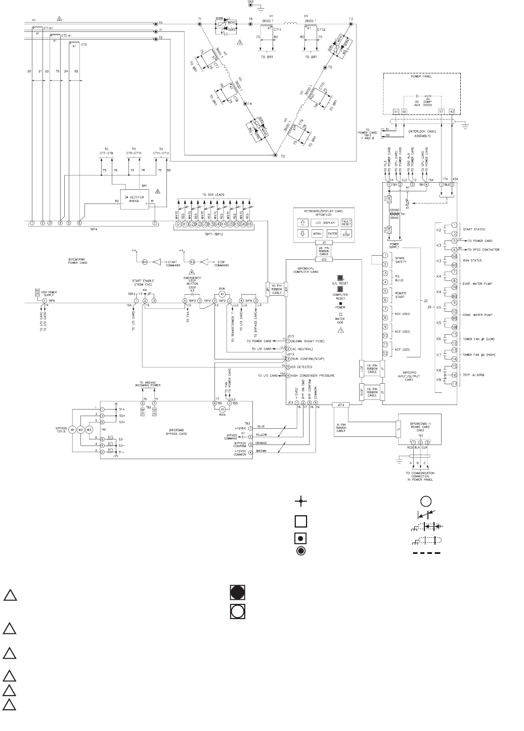
112
Fig. 53 — Benshaw, Inc. Solid-State Unit Mounted Starter Wiring Schematic (Low Voltage) (cont)
AUX —Auxiliary
BR —Bridge Rectifier
CB —Circuit Breaker
COND —Condenser
CPU —Central Processing Unit
CVC/
ICVC —Chiller Visual Controller
CT —Current Transformer
EVAP —Evaporator
FU —Fuse
GND —Ground
L—Main Supply Power
LL —Control Power Supply
M—Contactor
O/L —Overload Reset
PFCC —Power Factor
Correction Capacitor
RLA —Rated Load Amps
SCR —Silicone Controller Rectifier
ST —Shunt Trip
TB —Te r m i n a l B l o ck
Wire Node Symbol
may have terminal block
Benshaw supplied
terminal block
Te r m i na l S t r ip
Power Connection
PC Board Terminals
Twisted Pair
Twisted Shielded Pair
Shield Wire
Field Wiring
LEGEND
NOTES:
LED status with power applied and prior to run command.
Transformer T1 primary fuses FU1/FU2 value dependent on system voltage and model, per Chart 1.
Transformer connections per transformer nameplate connection diagram.
MOVs are used on power stack assemblies for system voltages of 200 through 460 vac (as shown).
Resistor/capacitor networks (DVDTs) are used on power stack assemblies in place of MOVs for a system
voltage of 575 vac (not shown).
K3 relay shown in deenergized state. K3 contact will close when power is supplied. K3 contact will open
on stop command or system fault.
CT1-CT3 are sized per Chart 2.
Optional.
1
"ON"
"OFF"
2
3
4
5
6
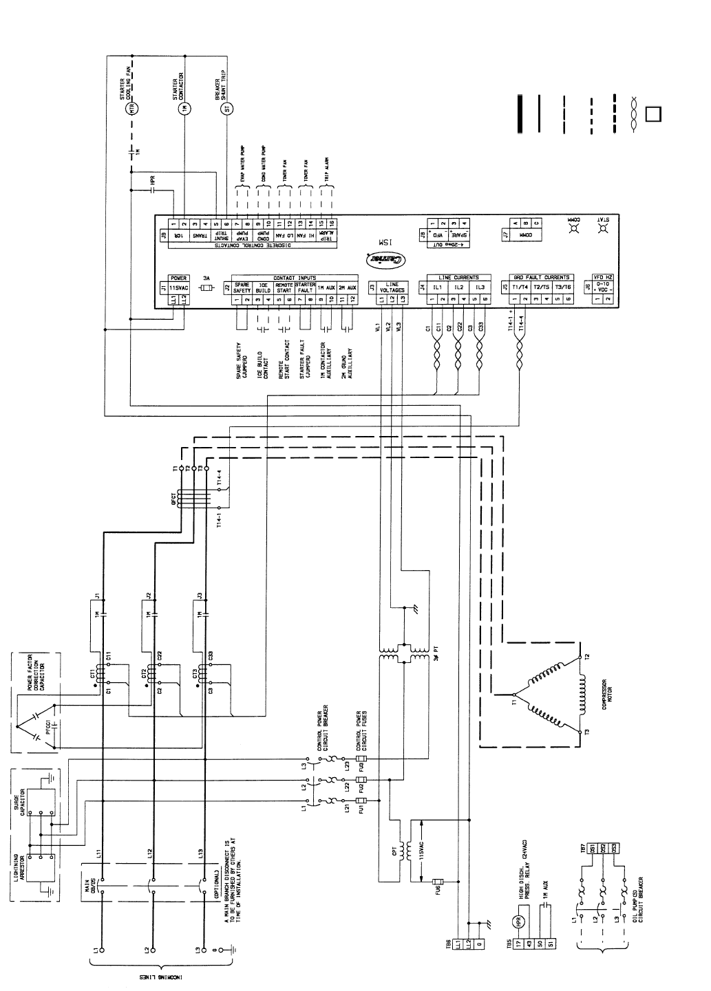
113
Fig. 54 — Typical Across-the-Line Starter Wiring Schematic (Medium Voltage)
LEGEND
AUX —Auxiliary
C—Contactor
CB —Circuit Breaker
COMM —Communication
COND —Condenser
CPT —Control Power
Transformer
CR —Control Relay
CT —Current Transformer
DS —Disconnect Switch
EVAP —Evaporator
FU —Fuse
G—Ground
GFCT —Ground Fault Current
Transformer
HPR —High Pressure Relay
ISM —Integrated Starter
Module
L—Main Power Supply
LL —Control Power Supply
LVG —Leaving
M—Contactor
MTR —Motor
PRESS —Pressure
PT —Power Transformer
ST —Shunt Trip
STAT —Status
TB —Terminal Block
TRANS —Transition
VFD —Variable Frequency
Drive
VL —Wire Label
Starter Vendor
Power Wiring
Starter Vendor
Control Wiring
Field Installed
Power Wiring
(supplied by others)
Field Installed
Control Wiring
(supplied by others)
Option — Starter
Vendor Wiring
Twisted Pair Wiring
by Starter Vendor
Customer Terminal
Connection
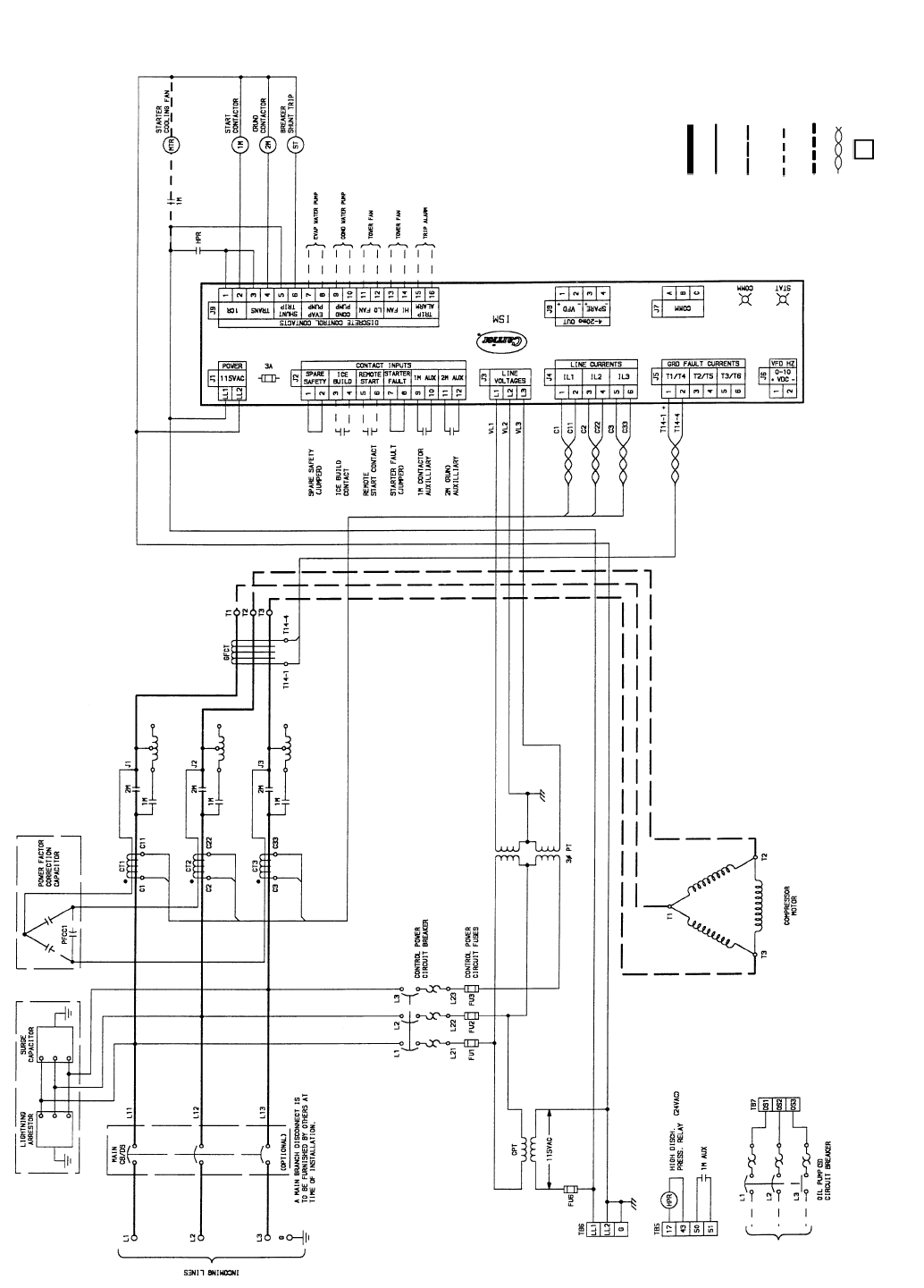
114
Fig. 55 — Typical Primary Reactor Starter Wiring Schematic (Medium Voltage)
LEGEND
AUX —Auxiliary
C—Contactor
CB —Circuit Breaker
COMM —Communication
COND —Condenser
CPT —Control Power
Transformer
CR —Control Relay
CT —Current Transformer
DS —Disconnect Switch
EVAP —Evaporator
FU —Fuse
G—Ground
GFCT —Ground Fault Current
Transformer
HPR —High Pressure Relay
ISM —Integrated Starter
Module
L—Main Power Supply
LL —Control Power Supply
LVG —Leaving
M—Contactor
MTR —Motor
PRESS —Pressure
PT —Power Transformer
ST —Shunt Trip
STAT —Status
TB —Terminal Block
TRANS —Transition
VFD —Variable Frequency
Drive
VL —Wire Label
Starter Vendor
Power Wir ing
Starter Vendor
Control Wiring
Field Installed
Power Wir ing
(supplied by others)
Field Installed
Control Wiring
(supplied by others)
Option — Starter
Vendor Wiring
Twisted Pair Wiring
by Starter Vendor
Customer Terminal
Connection
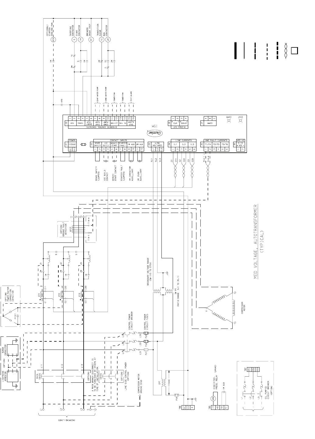
115
1A
Fig. 56 — Typical Autotransformer Starter Wiring Schematic (Medium Voltage)
LEGEND
AUX —Auxiliary
C—Contactor
CB —Circuit Breaker
COMM —Communication
COND —Condenser
CPT —Control Power
Transformer
CR —Control Relay
CT —Current Transformer
DISCH —Discharge
DS —Disconnect Switch
EVAP —Evaporator
FU —Fuse
GFCT —Ground Fault Current
Transformer
HPR —High Pressure Relay
ISM —Integrated Starter
Module
L—Main Power Supply
LL —Control Power Supply
MTR —Motor
PRESS —Pressure
PT —Power Transformer
ST —Shunt Trip
STAT —Status
TB —Te r m i n a l B l o c k
TC —Transition Clear
TRANS —Transition
VFD —Variable Frequency
Drive
VL —Wire Label
Starter Vendor
Power Wir ing
Starter Vendor
Control Wiring
Field Installed
Power Wir ing
(supplied by others)
Field Installed
Control Wiring
(supplied by others)
Option — Starter
Vendor Wiring
Twisted Pair Wiring
by Starter Vendor
Customer Terminal
Connection
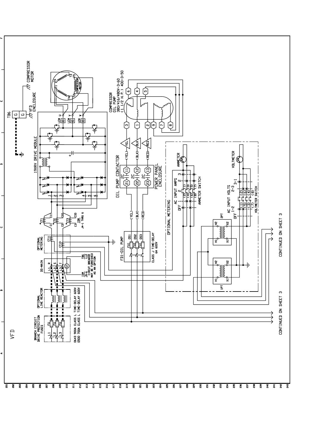
116
Fig. 57 — Typical Variable Frequency Drive (VFD) Wiring Schematic
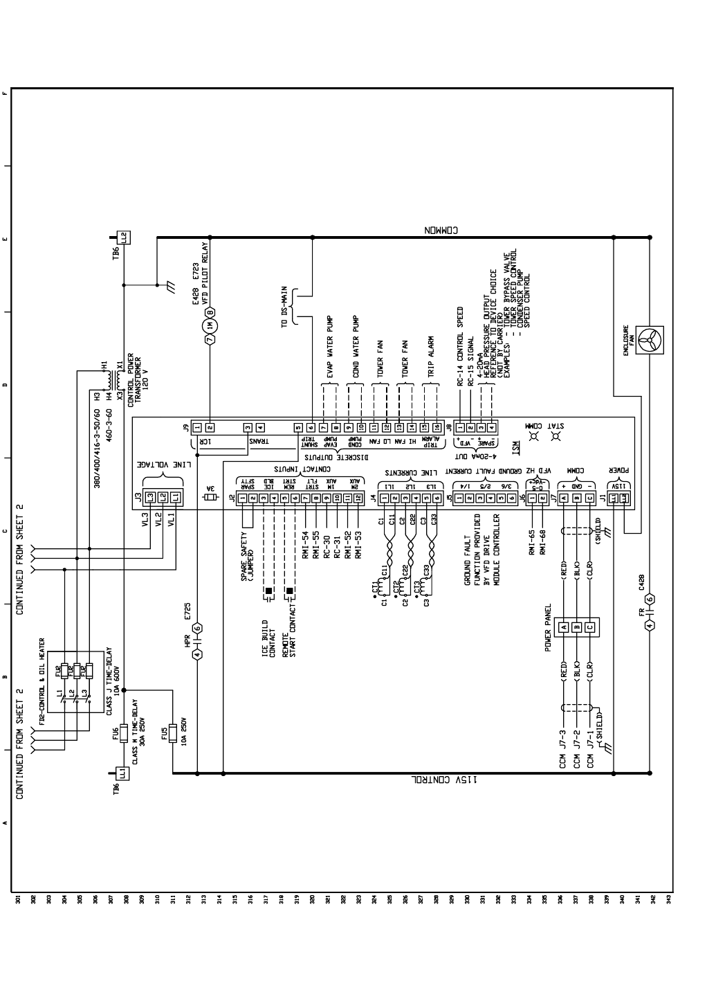
117
Fig. 57 — Typical Variable Frequency Drive (VFD) Wiring Schematic (cont)
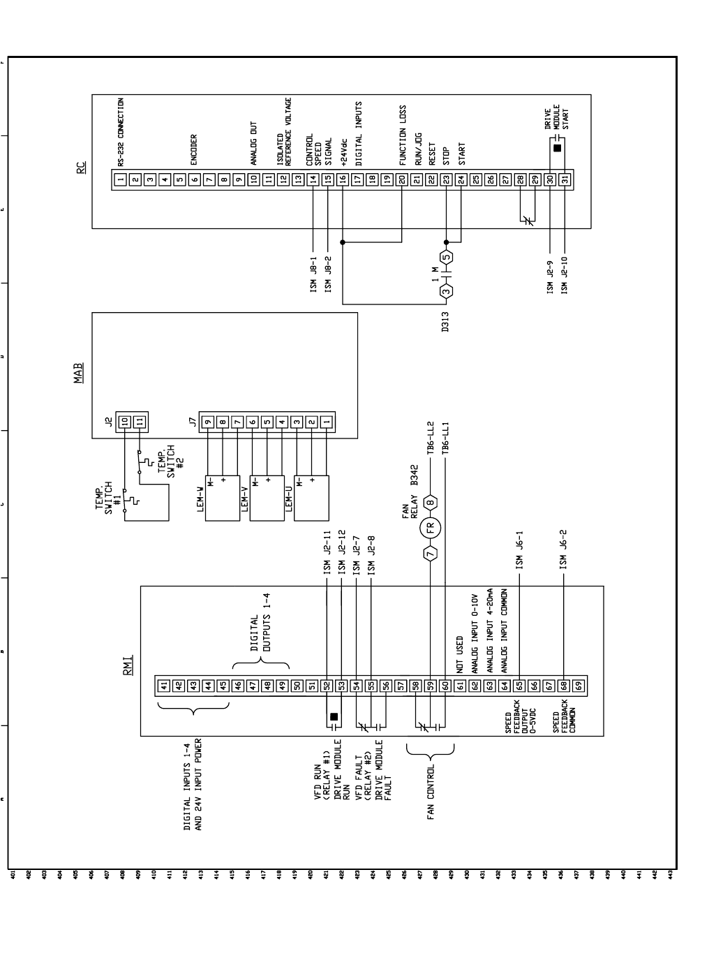
118
Fig. 57 — Typical Variable Frequency Drive (VFD) Wiring Schematic (cont)
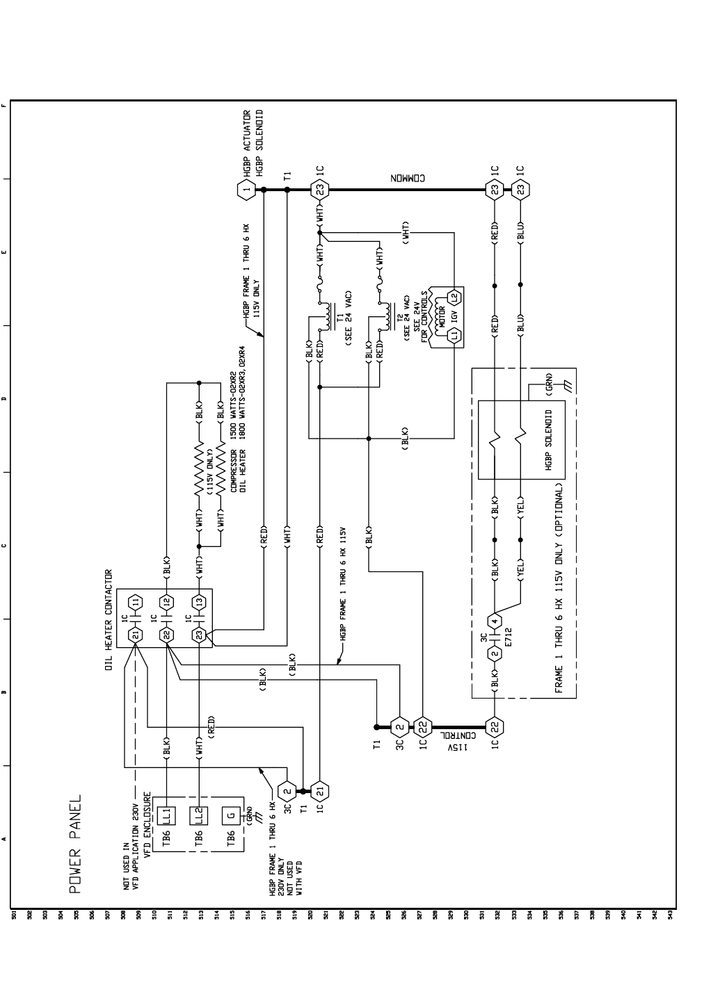
119
Fig. 57 — Typical Variable Frequency Drive (VFD) Wiring Schematic (cont)
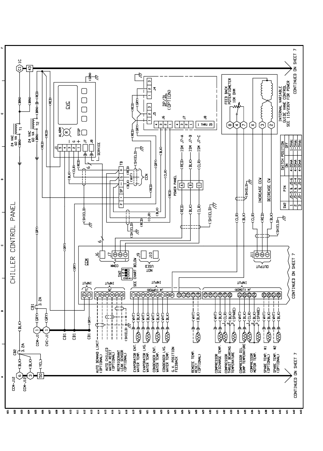
120
Fig. 57 — Typical Variable Frequency Drive (VFD) Wiring Schematic (cont)
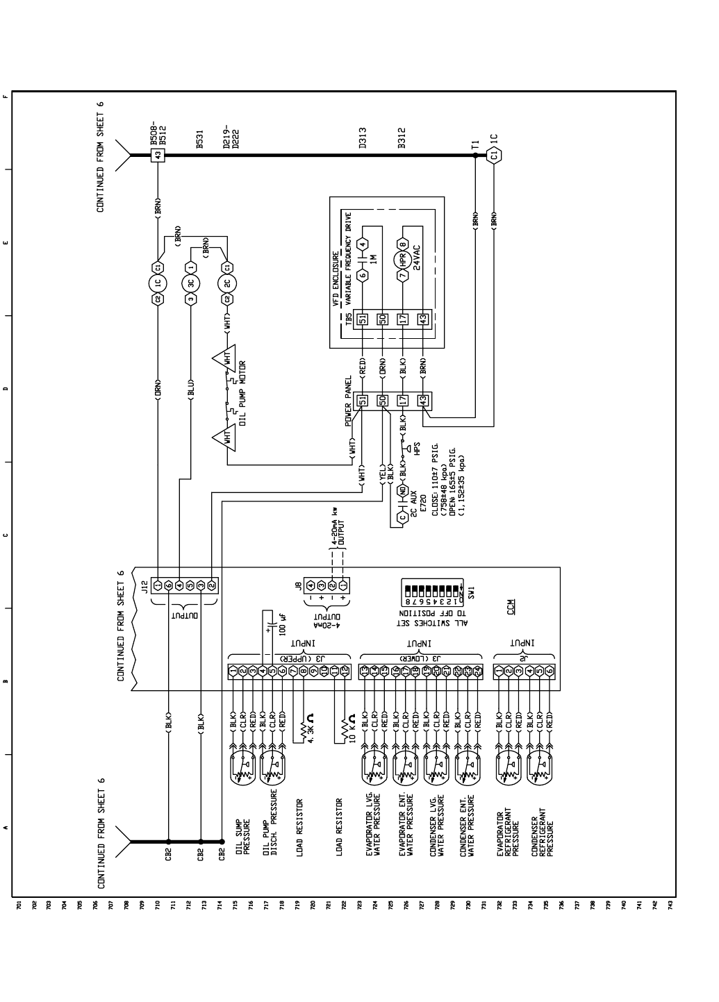
121
Fig. 57 — Typical Variable Frequency Drive (VFD) Wiring Schematic (cont)
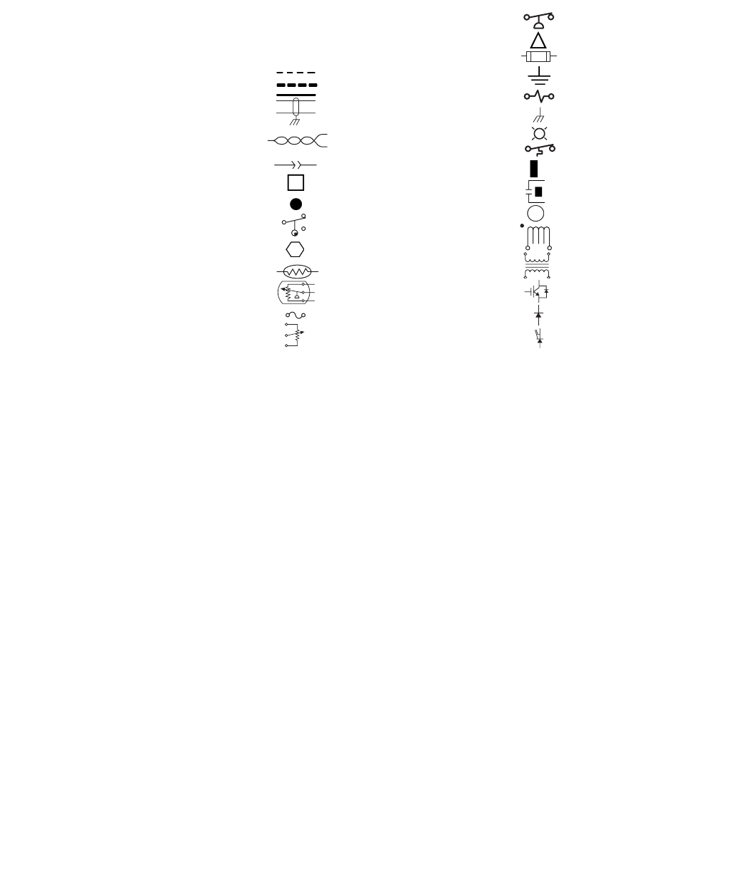
122
LEGEND FOR FIG. 57
AUX —Auxiliary
CB —Circuit Breaker
CCM —Chiller Control Module
CCN —Carrier Comfort Network
COMM —Communications
CT —Current Transformer
CVC —Chiller Visual Controller
DP/DL —Data Port/Data Link
DS —Disconnect Switch
FD —Fused Disconnect
FR —Fan Relay
FU —Fuse
G—Chassis Ground
GV —Guide Vane
HGBP —Hot Gas Bypass
HPR —High Discharge Pressure Relay
HPS —High Pressure Switch
HX —Heat Exchanger
ICVC —International Chiller Visual Controller
IGBT —Insulated Gate Bipolar Transistor
IGV —Inlet Guide Vane
ISM —Integrated Starter Module
J—Junction
LEM —Current Detector
MAB —Module Adapter Board
RC —Regulator Controller
RMI —Remote Metering Interface
ST —Shunt Trip
T—Transformer
TB —Terminal Block
VFD —Variable Frequency Drive
1C —Compressor Oil Heater Contactor
1M —Start Contactor
2C —Oil Pump Contactor
3C —Hot Gas Bypass Relay
Field Control Wiring
Field Power Wiring
Factory Wiring
Shielded Cable
Twisted Pair Wiring
Male/Female Connector
Terminal Block Connection
Wire Splice or Junction
Cam Switch
Component Terminal
Thermistor
Transducer
Fusible Link
Potentiometer
-
+
Pressure Switch
Compr Oil Pump Terminal
Cartridge Fuse
Earth Ground
Resistor
Chassis Ground
Light
Temperature Switch
Common Potential
Dry Contact
VFD Terminal
Current Transformer, Polarized
(Direction Determined by •)
Transformer
IGBT
Diode
Silicone Control Rectifier
123
INDEX
Abbreviations and Explanations, 4
Adding Refrigerant, 71
Adjusting the Refrigerant Charge, 71
After Extended Shutdown, 67
After Limited Shutdown, 66
Alarm (Trip) Output Contacts, 37
Attach to Network Device Control, 44
Automatic Soft Stop Amps Threshold, 47
Auto. Restart After Power Failure, 38
Before Initial Start-Up, 48
Capacity Override, 36
Carrier Comfort Network Interface, 54
Changing Oil Filter, 73
Charge Refrigerant Into Chiller, 63
Chilled Water Recycle Mode, 47
Chiller Control Module (CCM), 88
Chiller Dehydration, 53
Chiller Familiarization, 5
Chiller Information Nameplate, 5
Chiller Operating Condition (Check), 65
Chiller Tightness (Check), 48
Chillers with Isolation Valves, 70
Chillers with Storage Tanks, 69
Cold Weather Operation, 67
Compressor Bearing and Gear Maintenance, 74
Condenser, 5
Condenser Freeze Prevention, 38
Condenser Pump Control, 37
Control Algorithms Checkout Procedure, 77
Control Panel, 5
Control Modules, 87
Control Test, 77
Controls, 10
CVC/ICVC Operation and Menus, 15
Cooler, 5
Default Screen Freeze, 35
Definitions (Controls), 10
Demand Limit Control Option, 39
Design Set Points, (Input), 55
Details (Lubrication Cycle), 8
Display Messages (Check), 76
Dry Run to Test Start-Up Sequence, 65
Equipment Required, 48
Evaporator Freeze Protection, 38
Extended Shutdown (Preparation for), 66
Factory-Mounted Starter or Variable Frequency Drive, 7
General (Controls), 11
General Maintenance, 71
Guide Vane Linkage (Check), 72
Heat Exchanger Tubes and Flow Devices (Inspect), 74
High Altitude Locations, 63
High Discharge Temperature Control, 36
Ice Build Control, 43
Initial Start-Up, 64
Initial Start-Up Checklist for 19XR,XRV Hermetic
Centrifugal Liquid Chiller, CL-1
Inspect the Control Panel, 73
Instruct the Customer Operator, 65
Integrated Starter Module (ISM), 88
Introduction, 4
Job Data Required, 48
Kilowatt Output, 37
Lead/Lag Control, 40
Leak Rate, 71
Leak Test Chiller, 50
Local Occupied Schedule (Input), 55
Local Start-Up, 46
Lubrication Cycle, 8
Lubrication System (Check), 72
Manual Guide Vane Operation, 67
Motor and Lubricating Oil Cooling Cycle, 7
Motor-Compressor, 5
Motor Rotation (Check), 65
Notes on Module Operation, 87
Oil Changes, 73
Oil Charge, 55
Oil Cooler, 36
Oil Pressure and Compressor Stop (Check), 65
Oil Reclaim Filter, 73
Oil Reclaim System, 8
Oil Specification, 73
Oil Sump Temperature Control, 36
Open Oil Circuit Valves, 48
Operating Instructions, 66
Operating the Optional Pumpout Unit, 67
Operator Duties, 66
Optional Pumpout Compressor Water Piping (Check), 53
Optional Pumpout System Controls and
Compressor (Check), 63
Optional Pumpout System Maintenance, 75
Ordering Replacement Chiller Parts, 75
Overview (Troubleshooting Guide), 76
Perform a Control Test, 62
Physical Data, 90
PIC II System Components, 11
PIC II System Functions, 33
Power Up the Controls and Check the Oil Heater, 55
Preparation (Initial Start-Up), 64
Preparation (Pumpout and Refrigerant Transfer
Procedures), 67
Prepare the Chiller for Start-Up, 66
Pressure Transducers (Check), 75, 76
Prevent Accidental Start-Up, 65
Pumpout and Refrigerant Transfer Procedures, 67
Ramp Loading, 36
Refrigerant Filter, 73
Refrigerant Float System (Inspect), 74
Refrigerant Leak Detector, 37
Refrigerant Leak Testing, 71
Refrigerant Properties, 71
Refrigerant (Removing), 71
Refrigerant Tracer, 48
Refrigeration Cycle, 7
Refrigeration Log, 67
Relief Valves (Check), 53
Relief Valves and Piping (Inspect), 74
Remote Reset of Alarms, 37
Remote Start/Stop Controls, 36
Repair the Leak, Retest, and
Apply Standing Vacuum Test, 72
Replacing Defective Processor Modules, 88
Running System (Check), 66
Safety and Operating Controls (Check Monthly), 73
Safety Considerations, 1
Safety Controls, 34
Safety Shutdown, 47
Scheduled Maintenance, 73
Service Configurations (Input), 55
Service Ontime, 73
Service Operation, 45
Shipping Packaging (Remove), 48
Shunt Trip (Option), 35
Shutdown Sequence, 47
Software Configuration, 55
Solid-State Starters, 88
Spare Safety Inputs, 36
Standing Vacuum Test, 50
Starter (Check), 54
Starting Equipment, 9
Starting Equipment (Inspect), 75

Manufacturer reserves the right to discontinue, or change at any time, specifications or designs without notice and without incurring obligations.
PC 211 Catalog No. 531-982 Printed in U.S.A. Form 19XR-5SS Pg 124 6-01 Replaces: 19XR-4SS
Book 2
Ta b 5 a
Copyright 2001 Carrier Corporation
INDEX (cont)
Start-Up/Shutdown/Recycle Sequence, 46
Start the Chiller, 66
Stop the Chiller, 66
Storage Vessel, 7
Summary (Lubrication Cycle), 8
Surge Prevention Algorithm (Fixed Speed Chiller), 39
Surge Prevention Algorithm with VFD, 40
Surge Protection (Fixed Speed Chillers), 40
Surge Protection VFD Units, 40
System Components, 5
Temperature Sensors (Check), 76
Test After Service, Repair, or Major Leak, 71
Tighten All Gasketed Joints and Guide Vane Packing, 48
Tower Fan Relay Low and High, 38
Trim Refrigerant Charge, 72
Troubleshooting Guide, 76
Unit-Mounted Solid-State Starter, 9
Unit-Mounted VFD, 10
Unit-Mounted Wye-Delta Starter, 10
Using the Optional Storage Tank and Pumpout
System, 48
VFD Cooling Cycle, 8
Water/Brine Reset, 38
Water Leaks, 74
Water Piping (Inspect), 53
Water Treatment, 75
Weekly Maintenance, 72
Wiring (Inspect), 53
Manufacturer reserves the right to discontinue, or change at any time, specifications or designs without notice and without incurring obligations.
PC 211 Catalog No. 531-982 Printed in U.S.A. Form 19XR-5SS Pg CL-1 6-01 Replaces: 19XR-4SS
Book 2
Ta b 5 a
INITIAL START-UP CHECKLIST
FOR 19XR, XRV HERMETIC CENTRIFUGAL LIQUID CHILLER
(Remove and use for job file.)
MACHINE INFORMATION:
DESIGN CONDITIONS:
CONTROL/OIL HEATER: Volts 115 230
REFRIGERANT: Type: Charge
START-UP TO BE PERFORMED IN ACCORDANCE WITH APPROPRIATE MACHINE START-UP INSTRUCTIONS
JOB DATA REQUIRED:
1. Machine Installation Instructions . . . . . . . . . . . . . . . . . . Yes No
2. Machine Assembly, Wiring and Piping Diagrams . . . . . . Yes No
3. Starting Equipment Details and Wiring Diagrams. . . . . . Yes No
4. Applicable Design Data (see above). . . . . . . . . . . . . . . . Yes No
5. Diagrams and Instructions for Special Controls . . . . . . . Yes No
INITIAL MACHINE PRESSURE:
RECORD PRESSURE DROPS: Cooler Condenser
CHARGE REFRIGERANT: Initial Charge Final Charge After Trim
NAME JOB NO.
ADDRESS MODEL
CITY STATE ZIP S/N
TONS BRINE FLOW
RATE
TEMPERATURE
IN
TEMPERATURE
OUT
PRESSURE
DROP PA S S SUCTION
TEMPERATURE
CONDENSER
TEMPERATURE
COOLER ******
CONDENSER ******
COMPRESSOR: Volts RLA OLTA
STARTER: Mfg Type S/N
OIL PUMP: Volts RLA OLTA
CARRIER OBLIGATIONS: Assemble... . . . . . . . . . . . . . . . . Yes No
Leak Test . . . . . . . . . . . . . . . . . . . Yes No
Dehydrate . . . . . . . . . . . . . . . . . . Yes No
Charging . . . . . . . . . . . . . . . . . . . Yes No
Operating Instructions Hrs.
YES NO
Was Machine Tight?
If Not, Were Leaks Corrected?
Was Machine Dehydrated After Repairs?
CHECK OIL LEVEL AND RECORD: ADD OIL: Yes No
Amount:
1/2 Top sight glass
1/2 Bottom sight glass
3/4
1/4
3/4
1/4
CL-2
INSPECT WIRING AND RECORD ELECTRICAL DATA:
RATINGS:
Motor Voltage Motor(s) Amps Oil Pump Voltage Starter LRA Rating
Line Voltages: Motor Oil Pump Controls/Oil Heater
FIELD-INSTALLED STARTERS ONLY:
Check continuity T1 to T1, etc. (Motor to starter, disconnect motor leads T4, T5, T6.) Do not megger solid-state
starters; disconnect leads to motor and megger the leads.
STARTER: Electro-Mechanical Solid-State Manufacturer
Serial Number
Motor Load Current Transformer Ratio :
Solid-State Overloads Yes No
CONTROLS: SAFETY, OPERATING, ETC.
Perform Controls Test (Yes/No)
INITIAL START:
Line Up All Valves in Accordance With Instruction Manual:
Start Water Pumps and Establish Water Flow
Oil Level OK and Oil Temperature OK Check Oil Pump Rotation-Pressure
Check Compressor Motor Rotation (Motor End Sight Glass) and Record: Clockwise
Restart Compressor, Bring Up To Speed. Shut Down. Any Abnormal Coastdown Noise? Yes* No
*If yes, determine cause.
START MACHINE AND OPERATE. COMPLETE THE FOLLOWING:
A: Trim charge and record under Charge Refrigerant Into Chiller section on page 63.
B: Complete any remaining control calibration and record under Controls section (pages 10-45).
C: For unit mounted VFD complete pages 58-61.
D: Take at least two sets of operational log readings and record.
E: After machine has been successfully run and set up, shut down and mark shutdown oil and refrigerant levels.
F: Give operating instructions to owner’s operating personnel. Hours Given: Hours
G: Call your Carrier factory representative to report chiller start-up.
SIGNATURES:
CARRIER
TECHNICIAN
DATE
CUSTOMER
REPRESENTATIVE
DATE
MEGGER MOTOR “PHASE TO PHASE”“PHASE TO GROUND”
T1-T2 T1-T3 T2-T3 T1-G T2-G T3-G
10-Second Readings:
60-Second Readings:
Polarization Ratio:
PIC II CAUTION
COMPRESSOR MOTOR AND CONTROL PANEL MUST BE PROPERLY AND INDIVIDUALLY
CONNECTED BACK TO THE EARTH GROUND IN THE STARTER (IN ACCORDANCE WITH
CERTIFIED DRAWINGS).
Ye s
RUN MACHINE: Do these safeties shut down machine?
Condenser Water Flow Yes No
Chilled Water Flow Yes No
Pump Interlocks Yes No
CL-3
19XR, XRV PIC II SETPOINT TABLE CONFIGURATION SHEET
CVC/ICVC Software Version
Number:
CVC/ICVC Controller
Identification: BUS: ADDRESS:
DESCRIPTION RANGE UNITS DEFAULT VALUE
Base Demand Limit 40 to 100 % 100
ECW Setpoint 10 to 120 DEG F 60.0
LCW Setpoint 15 to 120 DEG F 50.0
Ice Build Setpoint 15 to 60 DEG F 40.0
Tower Fan High Setpoint 55 to 105 DEG F 75
CL-4
NOTE: Default setting is OCCUPIED 24 hours/day.
NOTE: Default setting is UNOCCUPIED 24 hours/day.
NOTE: Default setting is OCCUPIED 24 hours/day.
19XR, XRV PIC II TIME SCHEDULE CONFIGURATION SHEET OCCPC01S
Day Flag Occupied
Time Unoccupied
Time
MTWT F S SH
Period 1:
Period 2:
Period 3:
Period 4:
Period 5:
Period 6:
Period 7:
Period 8:
ICE BUILD 19XR, XRV PIC II TIME SCHEDULE CONFIGURATION SHEET OCCPC02S
Day Flag Occupied
Time Unoccupied
Time
MTWT F S SH
Period 1:
Period 2:
Period 3:
Period 4:
Period 5:
Period 6:
Period 7:
Period 8:
19XR, XRV PIC II TIME SCHEDULE CONFIGURATION SHEET OCCPC03S
Day Flag Occupied
Time Unoccupied
Time
MTWT F S SH
Period 1:
Period 2:
Period 3:
Period 4:
Period 5:
Period 6:
Period 7:
Period 8:
CL-5
CUT ALONG DOTTED LINE CUT ALONG DOTTED LINE
- - - - - - - - - - - - - - - - - - - - - - - - - - - - - - - - - - - - - - - - - - - - - - - - - - - - - - - - - - - - - - - - - - - - - - - - - - - - - - - - - - - - - - - - - - - - - - - - - - - - - - - - - - - - - - - - - - - - - - - - - - - - - - - - - - - - - - - - - - - - - - - - - - - - - - - - - - - - - - - - - - - - - - - - - - - - - - -- - - - - - - - - - - - - - - - - -
-
19XR, XRV PIC II ISM_CONF TABLE CONFIGURATION SHEET
DESCRIPTION RANGE UNITS DEFAULT VALUE
Starter Type
(0=Full, 1=Red, 2=SS/VFD) 0 to 2 1
Motor Rated Line Voltage 200 to 13200 VOLTS 460
Volt Transformer Ratio: 1 1 to 35 1
Overvoltage Threshold 105 to 115 % 115
Undervoltage Threshold 85 to 95 % 85
Over/Under Volt Time 1 to 10 SEC 5
Voltage% Imbalance 1 to 10 % 10
Voltage Imbalance Time 1 to 10 SEC 5
Motor Rated Load Amps 10 to 5000 AMPS 200
Motor Locked Rotor Trip 100 to 60000 AMPS 1000
Locked Rotor Start Delay 1 to 10 cycles 5
Starter LRA Rating 100 to 60000 AMPS 2000
Motor Current CT Ratio: 1 3 to 1000 100
Current% Imbalance 5 to 40 % 15
Current Imbalance Time 1 to 10 SEC 5
Grnd Fault CT’s? 0/1 NO/YES YES
Ground Fault CT Ratio: 1 150 150
Ground Fault Current 1 to 25 AMPS 15
Ground Fault Start Delay 1 to 20 cycles 10
Ground Fault Persistence 1 to 10 cycles 5
Single Cycle Dropout 0/1 DSABLE/ENABLE DSABLE
Frequency-60 Hz? (No=50) 0/1 NO/YES YES
Line Frequency Faulting 0/1 DSABLE/ENABLE DSABLE
CL-6
19XR, XRV PIC II OPTIONS TABLE CONFIGURATION SHEET
DESCRIPTION RANGE UNITS DEFAULT VALUE
Auto Restart Option 0/1 DSABLE/ENABLE DSABLE
Remote Contacts Option 0/1 DSABLE/ENABLE DSABLE
Soft Stop Amps Threshold 40 to 100 % 100
Surge/Hot Gas Bypass
Surge Limit/HGBP Option
Select: Surge=0, HGBP=1 0/1 0
Min. Load Point (T1, P1)
Surge/HGBP Delta T1 0.5 to 20 ˆF1.5
Surge/HGBP Delta P1 30 to 170 PSI 50
Full Load Point (T2, P2)
Surge/HGBP Delta T2 0.5 to 20 ˆF10
Surge/HGBP Delta P2 50 to 170 PSI 85
Surge/HGBP Deadband 0.5 to 3 ˆF1
Surge Protection
Surge Delta% Amps 5 to 20 % 10
Surge Time Period 7 to 10 MIN 8
Ice Build Control
Ice Build Option 0/1 DSABLE/ENABLE DSABLE
Ice Build Termination
0=Temp, 1=Contacts, 2=Both 0 to 2 0
Ice Build Recycle 0/1 DSABLE/ENABLE DSABLE
Refrigerant Leak Option 0/1 DSABLE/ENABLE DSABLE
Refrigerant Leak Alarm mA 4 to 20 mA 20
Head Pressure Reference
Delta P at 0% (4 mA) 20 to 60 psi 25
Delta P at 100% (20 mA) 20 to 60 psi 35
Minimum Output 0 to 100 % 0
CL-7
CUT ALONG DOTTED LINE CUT ALONG DOTTED LINE
- - - - - - - - - - - - - - - - - - - - - - - - - - - - - - - - - - - - - - - - - - - - - - - - - - - - - - - - - - - - - - - - - - - - - - - - - - - - - - - - - - - - - - - - - - - - - - - - - - - - - - - - - - - - - - - - - - - - - - - - - - - - - - - - - - - - - - - - - - - - - - - - - - - - - - - - - - - - - - - - - - - - - - - - - - - - - - -- - - - - - - - - - - - - - - - - -
-
19XR, XRV PIC II SETUP1 TABLE CONFIGURATION SHEET
DESCRIPTION RANGE UNITS DEFAULT VALUE
Comp Motor Temp Override 150 to 200 DEG F 200
Cond Press Override 90 to 165 PSI 125
Comp Discharge Alert 125 to 200 DEG F 200
Comp Thrust Brg Alert 165 to 185 DEG F 175
Chilled Medium 0/1 WATER/BRINE WATER
Chilled Water Deadband .5 to 2.0 ˆF1.0
Evap Refrig Trippoint 0.0 to 40.0 DEG F 33
Refrig Override Delta T 2.0 to 5.0 ˆF3
Condenser Freeze Point –20 to 35 DEG F 34
Evap Flow Delta P Cutout 0.5 to 50.0 PSI 5.0
Cond Flow Delta P Cutout 0.5 to 50.0 PSI 5.0
Water Flow Verify Time 0.5 to 5 MIN 5
Oil Press Verify Time 15 to 300 SEC 40
Recycle Control
Restart Delta T 2.0 to 10.0 DEG F 5
Shutdown Delta T 0.5 to 4.0 DEG F 1
SPARE ALERT/ALARM ENABLE
Disable=0, Lo=1/3, Hi=2/4
Spare Temp #1 Enable 0 to 4 0
Spare Temp #1 Limit –40 to 245 DEG F 245
Spare Temp #2 Enable 0 to 4 0
Spare Temp #2 Limit –40 to 245 DEG F 245
CL-8
19XR, XRV PIC II SETUP2 TABLE CONFIGURATION SHEET
DESCRIPTION STATUS UNITS DEFAULT VALUE
Capacity Control
Proportional Inc Band 2 to 10 6.5
Proportional DEC Band 2 to 10 6.0
Proportional ECW Gain 1 to 3 2.0
Guide Vane Travel Limit 30 to 100 % 80
Diffuser Control
Diffuser Option 0 to 1 DSABLE/ENABLE DSABLE
Guide Vane 25% Load Pt 0 to 78 % 25
Diffuser 25% Load Point 0 to 100 % 0
Guide Vane 50% Load Pt 0 to 78 % 50
Diffuser 50% Load Point 0 to 100 % 0
Guide Vane 75% Load Pt 0 to 78 % 50
Diffuser 75% Load Point 0 to 100 % 0
Diffuser Full Span mA 15 to 22 mA 18
VFD Speed Control
VFD Option 0/1 DSABLE/ENABLE DSABLE
VFD Gain 0.1 to 1.5 0.75
VFD Increase Step 1 to 5 % 2
VFD Minimum Speed 65 to 100 % 70
VFD Maximum Speed 90 to 100 % 100
VFD Current Limit 0 to 99999 Amp 250
CL-9
CUT ALONG DOTTED LINE CUT ALONG DOTTED LINE
- - - - - - - - - - - - - - - - - - - - - - - - - - - - - - - - - - - - - - - - - - - - - - - - - - - - - - - - - - - - - - - - - - - - - - - - - - - - - - - - - - - - - - - - - - - - - - - - - - - - - - - - - - - - - - - - - - - - - - - - - - - - - - - - - - - - - - - - - - - - - - - - - - - - - - - - - - - - - - - - - - - - - - - - - - - - - - -- - - - - - - - - - - - - - - - - -
-
19XR, XRV PIC II LEADLAG TABLE CONFIGURATION SHEET
DESCRIPTION RANGE UNITS DEFAULT VALUE
Lead Lag Control
LEAD/LAG: Configuration
DSABLE=0, LEAD=1,
LAG=2, STANDBY=3 0 to 3 0
Load Balance Option 0/1 DSABLE/ENABLE DSABLE
Common Sensor Option 0/1 DSABLE/ENABLE DSABLE
LAG% Capacity 25 to 75 % 50
LAG Address 1 to 236 92
LAG START Timer 2 to 60 MIN 10
LAG STOP Timer 2 to 60 MIN 10
PRESTART FAULT Timer 2 to 30 MIN 5
STANDBY Chiller Option 0/1 DSABLE/ENABLE DSABLE
STANDBY% Capacity 25 to 75 % 50
STANDBY Address 1 to 236 93
CL-10
19XR, XRV PIC II RAMP_DEM TABLE CONFIGURATION SHEET
19XR, XRV PIC II TEMP_CTL TABLE CONFIGURATION SHEET
DESCRIPTION RANGE UNITS DEFAULT VALUE
Pulldown Ramp Type:
Select: Temp=0, Load=1 0/1 1
Demand Limit + kW Ramp
Demand Limit Source
Select: Amps=0, kW=1 0/1 0
Motor Load Ramp% Min 5 to 20 10
Demand Limit Prop Band 3 to 15 % 10
Demand Limit At 20 mA 40 to 100 % 40
20 mA Demand Limit Opt 0/1 DSABLE/ENABLE DSABLE
Motor Rated Kilowatts 50 to 9999 kW 145
Demand Watts Interval 5 to 60 MIN 15
DESCRIPTION RANGE UNITS DEFAULT VALUE
Control Point
ECW Control Option 0/1 DSABLE/ENABLE DSABLE
Temp Pulldown Deg/Min 2 to 10 ˆF3
Temperature Reset
RESET TYPE 1
Degrees Reset At 20 mA –30 to 30 ˆF10
RESET TYPE 2
Remote Temp -> No Reset –40 to 245 DEG F 85
Remote Temp -> Full Reset –40 to 245 DEG F 65
Degrees Reset –30 to 30 ˆF10
RESET TYPE 3
CHW Delta T -> No Reset 0 to 15 ˆF10
CHW Delta T -> Full Reset 0 to 15 ˆF0
Degrees Reset –30 to 30 ˆF5
Select/Enable Reset Type 0 to 3 0
CL-11
CUT ALONG DOTTED LINE CUT ALONG DOTTED LINE
- - - - - - - - - - - - - - - - - - - - - - - - - - - - - - - - - - - - - - - - - - - - - - - - - - - - - - - - - - - - - - - - - - - - - - - - - - - - - - - - - - - - - - - - - - - - - - - - - - - - - - - - - - - - - - - - - - - - - - - - - - - - - - - - - - - - - - - - - - - - - - - - - - - - - - - - - - - - - - - - - - - - - - - - - - - - - - -- - - - - - - - - - - - - - - - - -
-
BROADCAST (BRODEF) CONFIGURATION SHEET
DESCRIPTION RANGE UNITS DEFAULT VALUE
Time Broadcast Enable DSABLE/ENABLE DSABLE
Daylight Savings
Start Month 1 to 12 4
Start Day of Week 1 to 7 7
Start Week 1 to 5 3
Start Time 00:00 to 24:00 HH:MM 02:00
Start Advance 0 to 360 MIN 60
Stop Month 1 to 12 10
Stop Day of Week 1 to 7 7
Stop Week 1 to 5 3
Stop Time 00:00 to 24:00 02:00
Stop Back 0 to 360 MIN 60

CL-12
UNIT-MOUNTED VFD CONFIGURATION SHEET
*Variable by job — refer to component nameplates and labels.
DESCRIPTION PARAMETER RANGE DEFAULT COMMENTS
Maximum Speed P.004 15 to H.022 * Job Sheet; 60 for 60 Hz and 50 for 50 Hz
Speed Display Scaling P.028 10 to 999 * Job Sheet; 60 for 60 Hz and 50 for 50 Hz
Motor Voltage H.000 100 to 690 * Selected line voltage
Frequency H.001 30 to 200 * 60 Hz = 60, 50 Hz = 50
Motor Amps H.002 Power Module Dependent * Selected motor 100% amps
Line Voltage H.021 300 to 565 * Selected line voltage
Over Frequency Limit H.022 30 to 210 * 60 Hz = 69, 50 Hz = 57

CL-13
CUT ALONG DOTTED LINE CUT ALONG DOTTED LINE
- - - - - - - - - - - - - - - - - - - - - - - - - - - - - - - - - - - - - - - - - - - - - - - - - - - - - - - - - - - - - - - - - - - - - - - - - - - - - - - - - - - - - - - - - - - - - - - - - - - - - - - - - - - - - - - - - - - - - - - - - - - - - - - - - - - - - - - - - - - - - - - - - - - - - - - - - - - - - - - - - - - - - - - - - - - - - - -- - - - - - - - - - - - - - - - - -
-
CVC/ICVC DISPLAY AND ALARM SHUTDOWN STATE RECORD SHEET
PRIMARY MESSAGE:
SECONDARY MESSAGE:
DATE: TIME:
COMPRESSOR ONTIME:
CHW IN
OILPRESS
CHW OUT
OIL TEMP
CDW IN CDW OUT
EVAP REF
COND REF
AMPS %
COMMUNICATION MESSAGE
CCN LOCAL RESET MENU
CL-14
CVC/ICVC DISPLAY AND ALARM SHUTDOWN STATE RECORD SHEET
PRIMARY MESSAGE:
SECONDARY MESSAGE:
DATE: TIME:
COMPRESSOR ONTIME:
CHW IN
OILPRESS
CHW OUT
OIL TEMP
CDW IN CDW OUT
EVAP REF
COND REF
AMPS %
COMMUNICATION MESSAGE
CCN LOCAL RESET MENU

Manufacturer reserves the right to discontinue, or change at any time, specifications or designs without notice and without incurring obligations.
PC 211 Catalog No. 531-982 Printed in U.S.A. Form 19XR-5SS Pg CL-16 6-01 Replaces: 19XR-4SS
Book 2
Ta b 5 a
Copyright 2001 Carrier Corporation
-
- - - - - - - - - - - - - - - - - - - - - - - - - - - - - - - - - - - - - - - - - - - - - - - - - - - - - - - - - - - - - - - - - - - - - - - - - - - - - - - - - - - - - - - - - - - - - - - - - - - - - - - - - - - - - - - - - - - - - - - - - - - - - - - - - - - - - - - - - - - - - - - - - - - - - - - - - - - - - - - - - - - - - - - - - - - - -- - - - - - - - - - - - - - - - - - - -
CUT ALONG DOTTED LINE CUT ALONG DOTTED LINE
