Carrier Evergreen 23Xrv Users Manual 3pd Reprint 910
23XRV to the manual 2f5066a0-4e7a-4acf-85c9-ade2ef55a790
2015-01-24
: Carrier Carrier-Evergreen-23Xrv-Users-Manual-311101 carrier-evergreen-23xrv-users-manual-311101 carrier pdf
Open the PDF directly: View PDF ![]() .
.
Page Count: 32
Copyright 2010 Carrier Corporation Form 23XRV-3PD
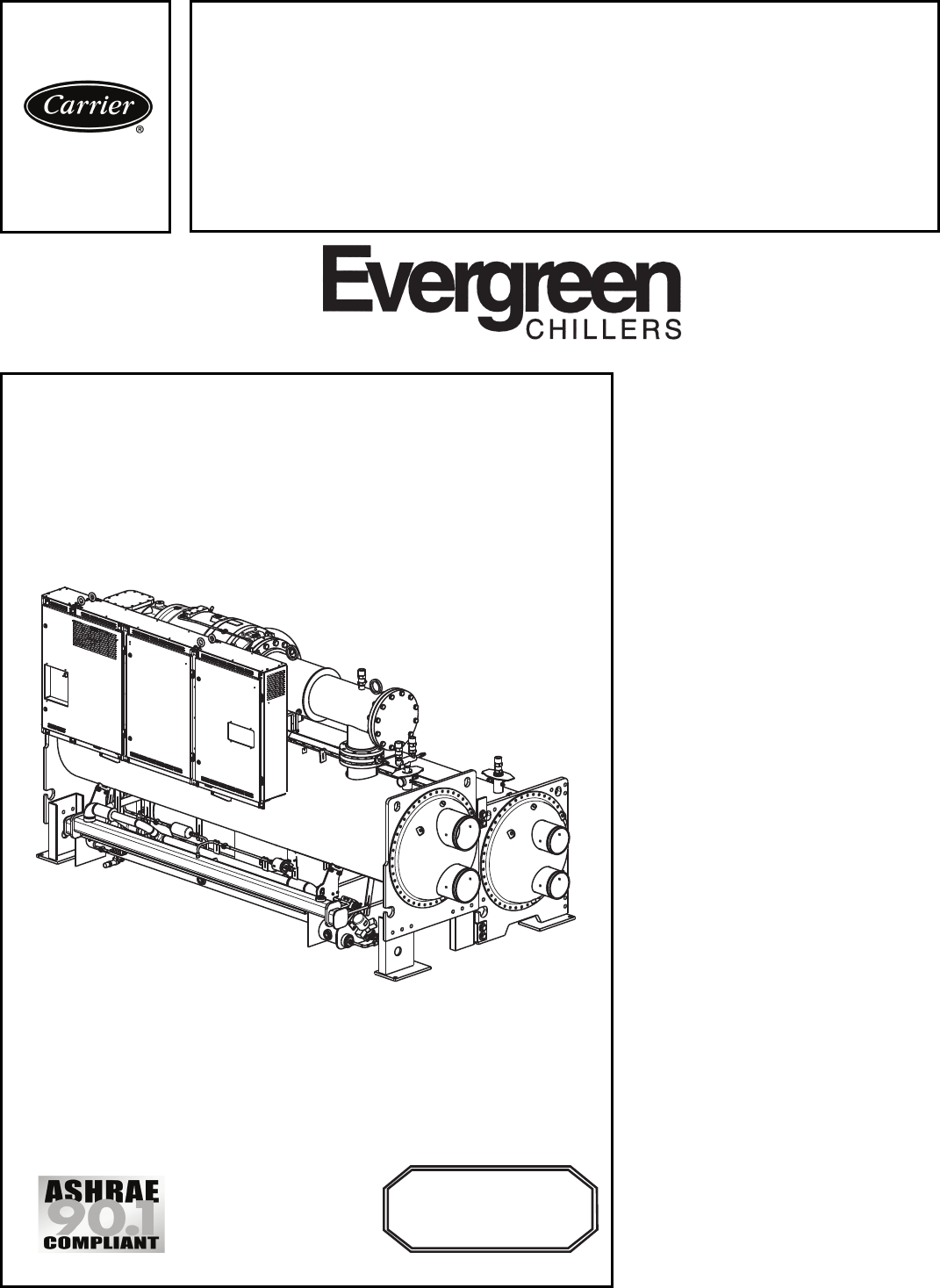
Carrier’s Evergreen® 23XRV chiller is
the world’s first integrated variable
speed, water-cooled, screw chiller.
It incorporates significant break-
throughs in water-cooled chiller tech-
nology to provide excellent reliability
and achieve superior efficiencies at
true operating conditions without com-
promising the environment.
The 23XRV chiller provides:
• Variable speed, positive
displacement screw compressor.
• Air Conditioning, Heating, and
Refrigerant Institute (AHRI) certified
efficiencies to 0.33 kW/ton (AHRI
IPLV).
• Chlorine-free HFC-134a refrigerant.
• IEEE-519 compliance for harmonic
distortion.
• An ideal solution for constant and
variable flow pumping systems.
Features/Benefits
Quality design and con-
struction make the Evergreen
23XRV chillers the best
choice for modern, efficient
chilled water plants.
Product reliability
The 23XRV chiller uses proven tech-
nology from Carrier’s existing line of
Evergreen chillers along with innova-
tions that increase reliability. The
23XRV compressors are designed for
extremely high reliability. The ad-
vanced tri-rotor compressor features a
balanced rotor geometry and shorter
screw lengths, resulting in vastly re-
duced compressor bearing loads and a
minimum L10 compressor bearing life
in excess of 500,000 hours when op-
erated at AHRI conditions.
EVERGREEN®
23XRV
High-Efficiency Variable Speed Screw Chiller
with FOXFIRE™ Compression Technology
50/60 Hz
HFC-134a
300 to 550 Nominal Tons (1055 to 1934 Nominal kW)
Product
Data
INNOVATION
INNOVATION
AWARD
AWARD
2008 AHR EXPO
2008 AHR EXPO®
WINNER – Green Building
23XRV
S
EISMI
C
OMPLIANT*
* Meets IBC 2006, ASCE-7-05, CBC 2007, and OSHPD seismic requirements.
®

2
Variable speed capacity control elimi-
nates slide valves, their associated loss-
es, and their potential failure modes.
Component count (both rotating and
total) has been minimized assuring
maximum reliability under a wide
range of operating conditions.
High efficiency
Per AHRI 550/590, chillers operate at
design conditions less than one percent
of the time. As a result, superior part
load efficiency is required for today’s
chilled water applications. The Ever-
green® 23XRV screw chiller maximizes
chiller efficiency by optimizing com-
pressor operation. Electric power con-
sumption drops dramatically when the
motor speed slows. The 23XRV screw
chiller delivers industry-leading inte-
grated part load values (IPLV) in an ex-
tremely broad range of applications
and climates.
Environmental leader
Carrier has long been committed to
the environment and its sustainability.
The Evergreen 23XRV screw chillers
provide our customers with a high-
efficiency, chlorine-free, long-term
solution unaffected by refrigerant
phase outs. Carrier’s decision to utilize
non-ozone depleting HFC-134a refrig-
erant provides our customers with a
safe and environmentally sound
product without compromising effi-
ciency. In addition, HFC-134a was
given an A1 safety rating by ASHRAE
(American Society of Heating,
Refrigerating and Air Conditioning
Engineers), meaning that it is the safest
refrigerant available.
Quality design
Positive displacement compres-
sion — Positive displacement com-
pression ensures stable operation
under all load conditions without the
possibility of compressor surge.
Superior oil management/cold
condenser water operation — All
Evergreen 23XRV chillers regulate oil
temperature, viscosity and pressure. A
patented process assures high quality
oil is delivered to the compressor bear-
ings by a positive displacement pump.
Bearing lubrication is assured, allowing
continuous operation with cold
condenser water at all loads. Screw
chillers no longer need to rely on dif-
ferential system pressure to effectively
lubricate the compressor. Should the
input power to the chiller be lost, the
system design assures proper lubrica-
tion of the bearings during coast down.
Small footprint — The Evergreen
23XRV chiller’s positive pressure
design reduces the chiller size by up
to 35% compared to negative-pressure
designs. Extremely high compression
efficiencies allow for compact,
high-efficiency chillers that require less
mechanical room floor space.
Constant or variable evaporator
flow — The 23XRV chiller combines
the advantages of positive displace-
ment compression with variable speed
capacity control. This process provides
a chiller that reacts substantially better
than chillers equipped with inlet guide
vanes or slide valves. This allows for
easier transition when bringing addi-
tional chillers on line in multiple chiller
plants and eliminates any possibility of
surge, regardless of the changes in the
system.
Low harmonic distortion — The
Evergreen 23XRV chiller will generate
less than 5% total harmonic distortion
at the input to the VFD (variable
frequency drive) without the use of
any external filters or line reactors.
This assures the VFD alone cannot
exceed the IEEE-519 standard for
distortion at the point of common
coupling. Ultra-low harmonics can
eliminate the need for complicated
harmonic system studies.
Low starting current (inrush) —
The inrush current is limited to the
chiller full load amps (rated load
amperes). No other starting means can
equal this level of starting current. The
combination of low current and ultra
low harmonics can reduce backup
generator size requirements.
0.99 power factor — The Ever-
green 23XRV chiller can operate at up
to 0.99 displacement power factor,
which helps building owners avoid
power factor penalties and decreases
electrical losses in cables and trans-
formers. High power factor may also
reduce KVA requirements, saving elec-
trical system costs on new projects or
freeing up electrical resources on exist-
ing systems operating near their maxi-
mum capacity.
Refrigerant-cooled VFD — Refrig-
erant cooling of the VFD minimizes
VFD size and ensures proper cooling
of the transistors for extended life.
Using R-134a refrigerant instead of
water also eliminates costly mainte-
nance associated with the water cool-
ing pump, heat exchanger and rubber
tubing used with water-cooled VFDs.
Optional seismic kit — A seismic
isolation package is available to meet
International Building Code and ASCE
7 seismic qualification requirements in
concurrence with ICC ES AC156 Ac-
ceptance Criteria for Seismic Qualifica-
tion by Shake-Table Testing of Non-
structural Components and Systems.
Hermetic motor — The Evergreen
23XRV chiller utilizes motors that are
hermetically sealed from the machine
room. Cooling is accomplished by
spraying liquid refrigerant on the
motor windings. This highly efficient
motor cooling method results in cooler-
running motors than could be realized
with air-cooled designs of the same
type.
In addition, Carrier’s hermetic de-
sign eliminates:
• Compressor shaft seals that require
maintenance and increase the likeli-
hood of refrigerant leaks.
Features/Benefits (cont)
Table of contents
Page
Features/Benefits . . . . . . . . . . . . . . . . . . . . . . . . . . . . . . . . . . . . . . . . . 1-4
Model Number Nomenclature . . . . . . . . . . . . . . . . . . . . . . . . . . . . . . . . . . . 4
Physical Data . . . . . . . . . . . . . . . . . . . . . . . . . . . . . . . . . . . . . . . . . . . . 5, 6
Options and Accessories . . . . . . . . . . . . . . . . . . . . . . . . . . . . . . . . . . . . . . 7
Dimensions . . . . . . . . . . . . . . . . . . . . . . . . . . . . . . . . . . . . . . . . . . . . . . . 8
Performance Data . . . . . . . . . . . . . . . . . . . . . . . . . . . . . . . . . . . . . . . . . . 9
Electrical Data . . . . . . . . . . . . . . . . . . . . . . . . . . . . . . . . . . . . . . . . . . . . . 10
Controls . . . . . . . . . . . . . . . . . . . . . . . . . . . . . . . . . . . . . . . . . . . . . . 11-14
Typical Piping and Wiring . . . . . . . . . . . . . . . . . . . . . . . . . . . . . . . . . . . . 15
Control Wiring Schematic . . . . . . . . . . . . . . . . . . . . . . . . . . . . . . . . . . . . 16
Application Data . . . . . . . . . . . . . . . . . . . . . . . . . . . . . . . . . . . . . . . . 17-23
Guide Specifications . . . . . . . . . . . . . . . . . . . . . . . . . . . . . . . . . . . . . 24-31
910

3
• Machine room cooling requirements
associated with air-cooled motors,
which dissipate heat to the mechan-
ical room.
• High noise levels common with air-
cooled motors, which radiate noise
to the machine room and adjacent
areas.
• Shaft alignment problems that occur
with open-drive designs during start-
up and operation, when equipment
temperature variations cause ther-
mal expansion.
Positive pressure design — Posi-
tive pressure designs eliminate the
need for costly low pressure contain-
ment devices, reducing the initial cost
of the system. The Evergreen® 23XRV
chiller’s positive pressure design en-
sures that air, moisture and other per-
formance degrading contaminants are
not sucked inside the chiller. Purge
units and their associated mainte-
nance are no longer necessary.
Optional refrigerant isolation
valves — The optional refrigerant
isolation valves allow the refrigerant
to be stored inside the chiller during
shipment from the factory, minimizing
start-up time. During servicing, the
“in-chiller” storage reduces refrigerant
loss and eliminates time-consuming
transfer procedures. As a self-contained
unit, the Evergreen 23XRV chiller does
not require additional remote storage
systems.
Optional pumpdown unit — Com-
bined with the refrigerant isolation
valves listed above, the optional pump-
down unit eliminates complex connec-
tions to portable transfer systems,
thereby reducing service costs. The op-
tional pumpdown compressor meets
Environmental Protection Agency’s
(EPA) vacuum level requirements that
mandate minimizing refrigerant emis-
sions during service.
Modular construction — The cool-
er, condenser, and compressor assem-
blies are bolted together, making Ever-
green 23XRV chillers ideally suited for
replacement jobs where ease of disas-
sembly and reassembly at the jobsite
are essential.
Single point power — The 23XRV
chiller features internal control power
transformers to provide low voltage
power (115 v and 24 vdc) for machine
controls. Simply connecting the three
input power leads to the VFD provides
all unit power.
Marine container shipment — The
compact design allows for open-top
container shipment to export destina-
tions, ensuring quality while reducing
shipping cost.
Heat exchanger combinations —
The Evergreen 23XRV chillers are
available with a complete line of heat
exchangers, ensuring the best combi-
nation of chiller components to meet
project specific tonnage and efficiency
requirements. One, 2 and 3-pass
arrangements are available to meet a
wide variety of flow conditions. Nozzle-
in-head and marine waterboxes are
available to meet 150 psig and
300 psig piping requirements.
Heat exchanger features
ASME certified construction — An
independent agency certifies the
design, manufacture, and testing of
all heat exchangers to American
Society of Mechanical Engineers
(ASME) standards, ensuring heat ex-
changer safety, reliability and long life.
The ASME U-stamp is applied to the
refrigerant side of the evaporator and
condenser and is applied to the water
side of heat exchangers when 300 psig
marine water boxes are provided.
High performance tubing — Carrier’s
Evergreen chillers utilize advances in heat
transfer technology, providing compact,
high-efficiency heat exchangers. Tubing
with advanced internally and externally
enhanced geometry improves chiller per-
formance by reducing overall resistance
to heat transfer while reducing fouling.
Cooler tube expansion — Cooler
tube expansion at center support
sheets prevents unwanted tube move-
ment and vibration, thereby reducing
the possibility of premature tube fail-
ure. Tube wall thickness is greater at
the expansion location, support sheets,
and end tube sheets in order to provide
maximum strength and long tube life.
Double-grooved end tube sheet
holes — This design provides a more
robust seal than single rolled joints, re-
ducing the possibility of leaks between
the water and refrigerant sides of the
chiller.
Condenser baffle — The baffle de-
flects hot discharge gas before it con-
tacts condenser tubes, reducing tube
vibration and wear while distributing
refrigerant more evenly over the
length of the vessel for improved
efficiency.
Closely spaced intermediate sup-
port sheets — Support sheets pre-
vent tube sagging and vibration, there-
by increasing heat exchanger life.
Refrigerant filter isolation valves
— These valves allow filter replace-
ment without pumping down the chill-
er, reducing service time and expense.
FLASC (flash subcooler) — The
subcooler, located in the bottom of the
condenser, increases the refrigeration
effect by cooling the condensed liquid
refrigerant to a lower temperature,
thereby reducing compressor power
consumption.
AccuMeter™ system — The
AccuMeter system regulates refrigerant
flow according to load conditions,
providing a liquid seal at all operating
conditions, eliminating unintentional
hot gas bypass.
Microprocessor controls
features
Direct Digital Product Integrated
control (PIC III) — Carrier’s PIC III
provides unmatched flexibility and
functionality. Each unit integrates
directly with the Carrier Comfort
Network® (CCN) system, providing a
solution to controls applications.
International Chiller Visual Con-
troller (ICVC) — The ICVC provides
an unparalleled ease of operation and
can be configured to display English or
metric values.
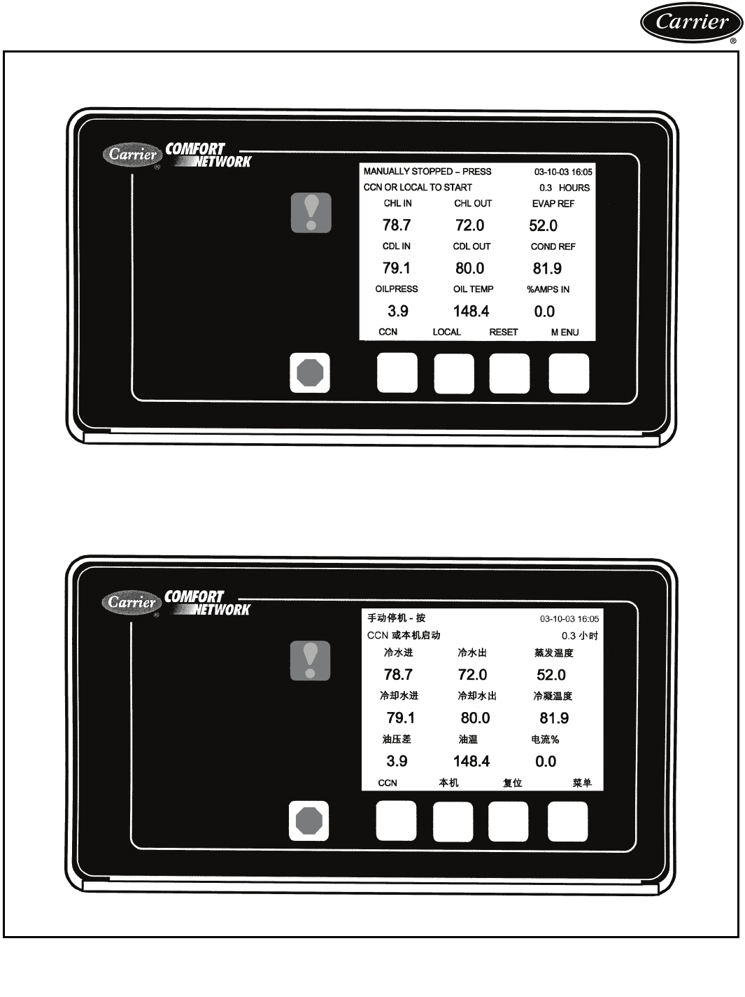
For convenience, a single display lo-
cated on the chiller VFD panel displays
chiller and VFD data. The VGA 320 x
240 element LCD (liquid crystal dis-
play) features 4 menu specific soft-
keys. The default display offers an
all-in-one glance review of key chiller
operation data, simplifying the interac-
tion between chiller and user.
The display includes 4 standard
languages:
•English
•Chinese
• Japanese
• Korean
Other languages are available.
Automatic capacity override —
This function unloads the compressor
whenever key safety limits are ap-
proached, increasing unit life. This
4
feature also allows the machine to
operate at reduced capacity, rather
than shut down, when key safety limits
are approached.
Chilled liquid reset — Reset can be
accomplished manually or automatical-
ly from the building management sys-
tem. For a given capacity, reset allows
operation at slower compressor
speeds, saving energy when warmer
chilled liquid can be used.
Demand limiting — This feature lim-
its the power draw of the chiller during
peak loading conditions. When incor-
porated into the Carrier Comfort
Network® building automation system,
a red line command holds chillers at
their present capacity and prevents any
other chillers from starting. If a load
shed signal is received, the compres-
sors are unloaded to avoid demand
charges whenever possible.
Ramp loading — Ramp loading en-
sures smooth pulldown of liquid loop
temperature and prevents a rapid
increase in compressor power con-
sumption during the pulldown period.
Automated controls test — The
test can be executed prior to start-up
to verify that the entire control system
is functioning properly.
365-day real time clock — This
feature allows the operator to program
a yearly schedule for each week, week-
ends, and holidays.
Occupancy schedules — Schedules
can be programmed into the controller
to ensure that the chiller operates
when cooling is required and remains
off when not needed by the tenants or
process.
Extensive service menu — Unau-
thorized access to the service menu
can be prevented through password
protection. Built-in diagnostic capabili-
ties assist in troubleshooting and rec-
ommend proper corrective action for
preset alarms, resulting in greater
working time.
Alarm file — This file maintains the
last 25 time-and date-stamped alarm
messages in memory. This function re-
duces troubleshooting time and cost.
Alert file — This file maintains the
last 25 alert messages in memory. This
function provides prognostic informa-
tion and corrective actions that can
avoid unit shutdown.
Configuration data backup —
Non-volatile memory provides
protection during power failures and
eliminates time consuming control
reconfiguration.
Features/Benefits (cont)
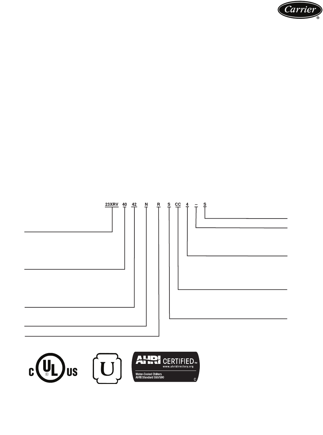
23XRV – High Efficiency
Variable Speed Screw Chiller
Cooler Size*
30-32
35-37
40-42
45-47
50-52
55-57
Condenser Size*
30-32
35-37
40-42
45-47
50-52
55-57
Economizer Option
E – With Economizer
N – No Economizer
Voltage Code
3 – 380-3-60
4 – 416-3-60
5 – 460-3-60
9 – 380/415-3-50
S – Special
R – Compressor
Not Used
Drive Amps Amps
Code In† Out†
AA 440 442
BA 520 442
BB 520 520
Motor Code
P T
Q U
R V
S
CC 608 608
ASME
‘U’ Stamp
AHRI (Air Conditioning, Heating
and Refrigeration Institute)
Performance Certified
Model number nomenclature
*First number denotes frame size.
†Maximum limits only. Additional application
limits apply that may reduce these ampacities.
a23-1648
Quality Assurance
Certified to ISO 9001:2000
S
EISMI
C
OMPLIANT*
* Meets IBC 2006, ASCE-7-05, CBC 2007, and OSHPD seismic requirements.
5
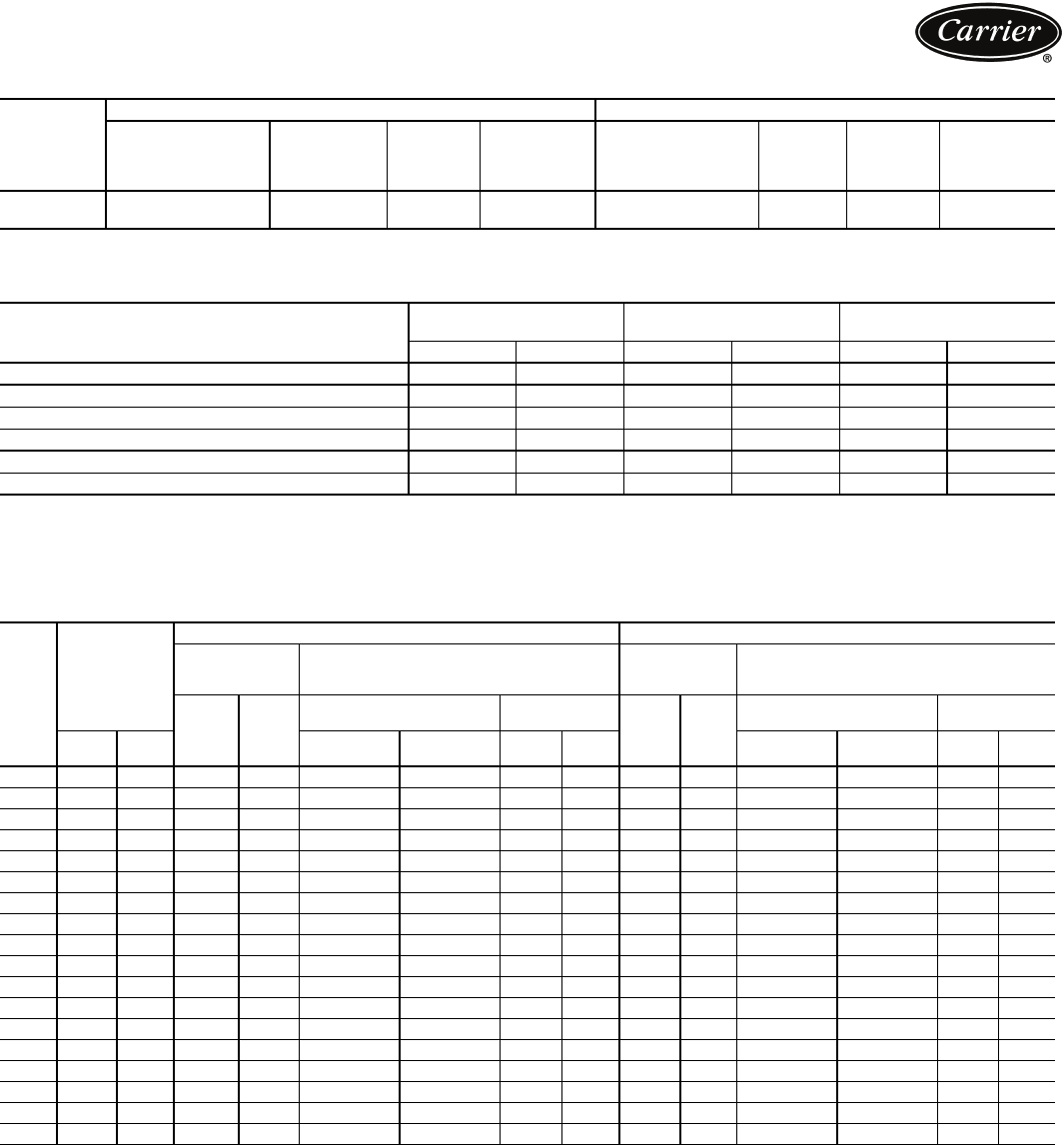
23XRV COMPRESSOR AND MOTOR WEIGHTS
COMPONENT WEIGHTS
LEGEND
23XRV HEAT EXCHANGER WEIGHTS
COND — Condenser
*Rigging weights are for standard tubes of standard wall thickness (EDE and
Spikefin 3, 0.025-in. [0.635 mm] wall).
NOTES:
1. Cooler includes the suction elbow and 1/2 the distribution piping weight.
2. Condenser includes float valve and sump, discharge elbow, and 1/2 the
distribution piping weight.
3. For special tubes, refer to the 23XRV Computer Selection Program.
4. All weights for standard 2-pass NIH (nozzle-in-head) design with vic-
taulic grooves.
MOTOR
SIZE
ENGLISH SI
Total
Compressor
Weight
(lb)
Stator
Weight
(lb)
Rotor
Weight
(lb)
Motor
Terminal
Cover
(lb)
Compressor
Weight
(kg)
Stator
Weight
(kg)
Rotor
Weight
(kg)
Motor
Terminal
Cover
(kg)
P, Q , R , S ,
T,U,V 4866 441 229 46 2207 200 104 21
COMPONENT
FRAME 3 HEAT
EXCHANGER
FRAME 4 HEAT
EXCHANGER
FRAME 5 HEAT
EXCHANGER
lb kg lb kg lb kg
Isolation Valves 70 32 70 32 115 52
Suction Elbow 179 81 237 108232 105
Discharge Elbow/Muffler 747 339 747 339 747 339
Control Center/VFD 1650 749 1650 749 1650 749
Vaporizer and Oil Sump 700 318700 318700 318
Economizer 542 246 542 246 542 246
VFD — Variable Frequency Drive
CODE
NUMBER
OF TUBES
ENGLISH METRIC (SI)
Dry Rigging
Weight
(lb)*
Machine Charge
Dry Rigging
Weight
(kg)*
Machine Charge
Cooler
Only
Cond.
Only
Refrigerant
Weight (lb)
Liquid Weight
(lb) Cooler
Only
Cond.
Only
Refrigerant
Weight (kg)
Liquid Weight
(kg)
Cooler Cond. With
Economizer
Without
Economizer Cooler Cond. With
Economizer
Without
Economizer Cooler Cond.
30 200 21841483617 800 650 464 464 1877 1676 363 295 210 210
31 240 266 4330 3818800 650 531 542 1959 1769 363 295 241 246
32 2823154522 4023 800 650 601 621 2046 1860 363 295 273 282
35 200 2184419 4529 910 760 511 513 2000 2089 413 345 232 233
36 240 266 4627 4758910 760 587 602 2094 2195 413 345 266 274
37 2823154845 4992 910 760 667 692 2193 2299 413 345 303 314
40 324 366 50084962 900 825 863 915 2675 2746 408375 391 415
41 364 415 51785155 900 825 930 995 27582839 408375 422 451
42 400 464 5326 5347 900 825 990 1074 2832 2932 408375 449 487
45 324 366 5463 5525 1015 960 9389982882 3001 460 436 425 453
46 364 415 5659 5747 1015 960 1014 1088 2976 3108460 436 460 494
47 400 464 5830 5967 1015 960 1083 1179 3061 3214 460 436 491 535
50 431 507 5827 6013 1250 1100 1101 1225 3182 3304 567 499 499 556
51 4855566053 6206 1250 1100 1192 1304 3294 3397 567 499 541 591
52 519 602 6196 6387 1250 1100 12481379 3364 3485 567 499 566 626
55 431 507 6370 67081430 1280 1201 1339 3429 3620 649 581545607
56 4855566631 6930 1430 1280 1304 1429 3556 3726 649 581591648
57 519 602 6795 71381430 1280 1369 1514 3636 3826 649 581621687
Physical data
6
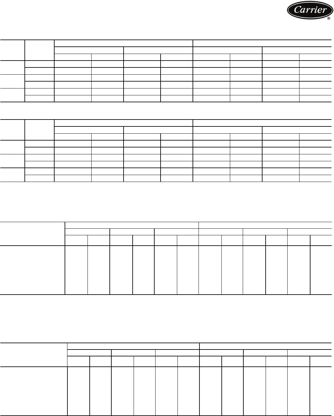
ADDITIONAL WEIGHTS FOR 23XRV MARINE WATERBOXES*
150 psig (1034 kPa) MARINE WATERBOXES
300 psig (2068 kPa) MARINE WATERBOXES
*Add to cooler and condenser weights for total weights. Cooler and condenser weights may be found in the 23XRV Heat Exchanger
Weights table on page 5. The first digit of the heat exchanger code (first column) is the heat exchanger frame size.
23XRV WATERBOX COVER WEIGHTS — ENGLISH (lb)
FRAMES 3, 4, AND 5
LEGEND *Nozzle end weight/return end weight.
NOTE: Weight for NIH 2-pass cover, 150 psig (1034 kPa), is included in
the heat exchanger weights shown on page 5.
23XRV WATERBOX COVER WEIGHTS — SI (kg)
FRAMES 3, 4, AND 5
LEGEND *Nozzle end weight/return end weight.
NOTE: Weight for NIH 2-pass cover, 150 psig (1034 kPa), is included in
the heat exchanger weights shown on page 5.
FRAME
NUMBER
OF
PASSES
ENGLISH (lb) SI (kg)
Cooler Condenser Cooler Condenser
Rigging Wgt Liquid Wgt Rigging Wgt Liquid Wgt Rigging Wgt Liquid Wgt Rigging Wgt Liquid Wgt
31 and 3 730 700 N/A N/A 331 318N/A N/A
2 365 350 365 350 166 159 166 159
41 and 3 1888 908N/A N/A 856 412 N/A N/A
2 944 452 989 452 428205 449 205
51 and 3 2445 1019 N/A N/A 1109 462 N/A N/A
2 1223 510 1195 499 555 231 542 226
FRAME
NUMBER
OF
PASSES
ENGLISH (lb) SI (kg)
Cooler Condenser Cooler Condenser
Rigging Wgt Liquid Wgt Rigging Wgt Liquid Wgt Rigging Wgt Liquid Wgt Rigging Wgt Liquid Wgt
31 and 3 860 700 N/A N/A 390 318N/A N/A
2 430 350 430 350 195 159 195 159
41 and 3 2162 908N/A N/A 981 412 N/A N/A
2 1552 393 1641 393 704 178744 178
51 and 3 2655 1019 N/A N/A 1204 462 N/A N/A
2 1965 439 1909 418891 199 866 190
WATERBOX
DESCRIPTION
COOLER CONDENSER
Frame 3 Frame 4 Frame 5 Frame 3 Frame 4 Frame 5
Victaulic
Nozzles Flanged Victaulic
Nozzles Flanged Victaulic
Nozzles Flanged Victaulic
Nozzles Flanged Victaulic
Nozzles Flanged Victaulic
Nozzles Flanged
NIH,1 pass Cover 150 psig 282318148185168229 282318148185168229
NIH,2 pass Cover 150 psig 287 340 202 256 222 275 287 340 191 245 224 298
NIH,3 pass Cover 150 psig 294 310 472 488 617 634 294 310 503 519 628655
NIH Plain End, 150 psig 243 243 138138154 154 225 225 138138154 154
MWB End Cover, 150 psig*243/315 243/315 138/314 138/314 154/390 154/390 225/234 225/234 138/314 138/314 154/390 154/390
NIH,1 pass Cover 300 psig 411 486 633 709 764 840 411 486 633 709 764 840
NIH,2 pass Cover 300 psig 411 518626 733 760 867 411 518622 729 727 878
NIH,3 pass Cover 300 psig 433 468660 694 795 830 433 468655 689785838
NIH Plain End, 300 psig 294 294 522 522 658658270 270 522 522 658658
MWB End Cover, 300 psig*445/619 445/619 522/522 522/522 658/658658/658359/474 359/474 658/658658/658658/658658/658
NIH — Nozzle-in-Head
MWB — Marine Waterbox
WATERBOX
DESCRIPTION
COOLER CONDENSER
Frame 3Frame 4Frame 5Frame 3Frame 4Frame 5
Victaulic
Nozzles Flanged Victaulic
Nozzles Flanged Victaulic
Nozzles Flanged Victaulic
Nozzles Flanged Victaulic
Nozzles Flanged Victaulic
Nozzles Flanged
NIH,1 pass Cover 1034 kPa 128144 67 8476104128144 67 8476104
NIH,2 pass Cover 1034 kPa 130 154 92 116 101 125 130 154 87 111 102 135
NIH,3 pass Cover 1034 kPa 133 141 214 221 280288 133 141 228235 285297
NIH Plain End, 1034 kPa 110 110 63 63 70 70 102 102 63 63 70 70
MWB End Cover, 2068 kPa*110/143 110/143 63/142 63/142 70/177 70/177 102/106 102/106 63/142 63/142 70/177 70/177
NIH,1 pass Cover 2068 kPa 186220287322347381186220287322347381
NIH,2 pass Cover 2068 kPa 186235284332344393186235282331330398
NIH,3 pass Cover 2068 kPa 196 212 299 315 361 376 196 212 297 313 356 380
NIH Plain End, 2068 kPa 132 132 237 237 298298122 122 237 237 298298
MWB End Cover, 2068 kPa*202/281202/281 237/237 237/237 298/298298/298163/215 163/215 298/298298/298298/298298/298
NIH — Nozzle-in-Head
MWB — Marine Waterbox
Physical data (cont)
7
*Factory-installed.
†Field-installed.
**Standard waterbox nozzles are victaulic type. Flanged nozzles are
available as an option with either nozzle-in-head type waterboxes or
marine waterboxes.
††Optional marine waterboxes available for 23XRV heat exchanger
frames 3-5 only. Standard waterboxes for 23XRV are nozzle-in-head
type, 150 psig (1034 kPa).
***Sponsored by ASHRAE (American Society of Heating, Refrigerating,
and Air Conditioning Engineers).
†††Registered trademark of Echelon Corporation.
ITEM OPTION*ACCESSORY†
.028 or .035 in. (0.711 or 0.889 mm) Internally/Externally Enhanced Copper Tubing — Cooler/Condenser X
.028 or .035 in. (0.711 or 0.889 mm) Internally/Externally Enhanced Cupronickel Tubing — Condenser X
.028 or .035 in. (0.711 or 0.889 mm) Smooth Bore/Externally Enhanced Copper Tubing — Cooler/Condenser X
.028 or .035 in. (0.711 or 0.889 mm) Smooth Bore/Externally Enhanced Cupronickel Tubing — Condenser X
Flanged Cooler and/or Condenser Waterbox Nozzles** X
Hinged Waterboxes X
Marine Waterboxes, 150 psig (1034 kPa)†† X
Marine Waterboxes, 300 psig (2068 kPa)†† X
Nozzle-in Head Waterbox, 300 psig (2068 kPa) X
One, 2, or 3 Pass Cooler or Condenser Waterside Construction X
Seismic Kit X
Zinc Anodes X
100K AIC (Amp Interrupt Capacity) High Interrupt Circuit Breaker with Shunt Trip X
Analog Voltmeter and Ammeter with 3 Phase Selector Switch X
BACnet*** Communications X
LonWorks††† Carrier Translator X
Sensor Package X
Refrigerant Isolation Valves X
Separate Storage Tank and Pumpout Unit X
Shipped Factory Charged with Refrigerant X
Stand-Alone Pumpout Unit X
Unit-Mounted Pumpout Unit X
Hot Gas Bypass X
Soleplate Package X
Spring Isolator Kit X
Acoustical Sound Insulation Kit X
Full Cold Surface Thermal Insulation (Except Waterbox Covers) X
Customer Factory Performance Testing X
Export Crating X
Extended Warranty (North American Operations [NAO] only) X
Service Contract X
Options and accessories
910
8
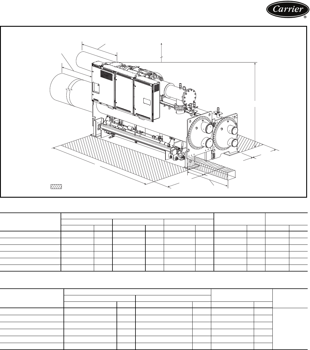
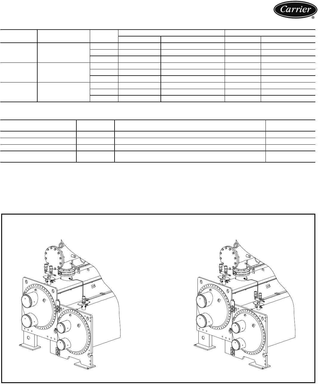
23XRV DIMENSIONS (NOZZLE-IN-HEAD WATERBOX)
23XRV DIMENSIONS (MARINE WATERBOX)
*Assumes both cooler and condenser nozzles on same end of chiller.
†1 or 3 pass length applies if cooler is a 1 or 3 pass design.
NOTES:
1. Service access should be provided per American Society of Heat-
ing, Refrigerating, and Air Conditioning Engineers (ASHRAE) 15,
latest edition, National Fire Protection Association (NFPA) 70, and
local safety code.
2. Allow at least 3 ft (915 mm) overhead clearance for service rigging
for the compressor.
3. Certified drawings available upon request.
4. Marine waterboxes may add 6 in. (152 mm), to the width of the
machine. See certified drawings for details.
5. ‘A’ length and ‘B’ width dimensions shown are for standard
150 psig (1034 kPa) design and victaulic connections. The
300 psig (2068 kPa) design and/or flanges will add length. See cer-
tified drawings.
6. Dished head waterbox covers not available for the 3-pass design.
HEAT EXCHANGER
SIZE
A (Length, with Nozzle-in-Head Waterbox) B (Width) C (Height)
1 Pass 2-Pass*3 Pass
ft-in. mm ft-in. mm ft-in. mm ft-in. mm ft-in. mm
30 to 32 14- 31/44350 13- 81/44172 14- 31/44350 6- 4 1930 7- 25/82200
35 to 37 15-113/44870 15- 43/44693 15-113/44870 6- 4 1930 7- 25/82200
40 to 42 14- 9 4496 14- 31/84347 14- 6 4420 6- 81/22045 7- 61/22299
45 to 47 16- 51/25017 15-115/84867 16- 21/24940 6- 81/22045 7- 61/22299
50 to 52 14-10 4521 14- 41/24382 14- 61/24432 6-113/42127 7- 63/42305
55 to 57 16- 61/25042 16- 1 4902 16- 3 4953 6-113/42127 7- 63/42305
HEAT EXCHANGER
SIZE
A (Length, Marine Waterbox) B (Width) C (Height)2-Pass*1 or 3 Pass†
ft-in. mm ft-in. mm ft-in. mm
30 to 32 14- 9 4496 16- 43/44997 6- 93/82067
See unit
certified
drawings
35 to 37 16- 51/25017 18-1
1/455186- 93/82067
40 to 42 15- 23/44642 16- 31/450866-9
3/42076
45 to 47 16-113/45163 18-4
3/45607 6- 93/42076
50 to 52 15- 31/24661 16- 81/25093 7- 1 2159
55 to 57 17- 0 518218- 5 5613 7- 1 2159
B
(WIDEST POINT)
2’ MIN
(610 mm)
4’-10” MIN
(1475 mm)
A
C
FRAME R COMPRESSOR 3’-0” (915mm)
RECOMMENDED OVERHEAD SERVICE CLEARANCE
MOTOR SERVICE
CLEARANCE
1’-10” (559 mm)
TUBE REMOVAL
SPACE FOR
EITHER END
SIZES 30-32, 40-42
50-52
14’-3” (4343 mm)
SIZES 35-37, 45-47
55-57
14’-0” (4267 mm)
SERVICE AREA
4’ MIN
(1219 mm)
23XRV DIMENSIONS
a23-1646
Dimensions
9
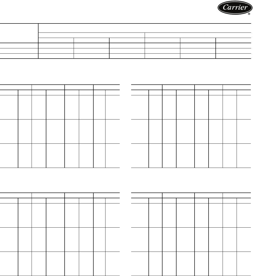
NOZZLE SIZE
23XRV HEAT EXCHANGER MIN/MAX FLOW RATES*
ENGLISH (GPM)
*Flow rates based on standard tubes in the cooler and condenser. Minimum flow based on tube velocity of 3 ft/sec (0.91 m/sec);
maximum flow based on tube velocity of 12 ft/sec (3.66 m/sec). Consult the factory if variable primary flow.
SI (L/s)
*Flow rates based on standard tubes in the cooler and condenser. Minimum flow based on tube velocity of 3 ft/sec (0.91 m/sec);
maximum flow based on tube velocity of 12 ft/sec (3.66 m/sec). Consult the factory if variable primary flow.
FRAME
SIZE
NOZZLE SIZE (in.)
(Nominal Pipe Size)
Cooler Condenser
1-Pass 2-Pass 3-Pass 1-Pass 2-Pass 3-Pass
310 8610 86
410 8610 86
510 861010 8
COOLER 1 PASS 2 PASS 3 PASS
Frame Size Min Max Min Max Min Max
3
30 611 2,444 305 1222 204 815
31 733 2,933 367 1466 244 978
32 855 3,422 4281710 285 1141
35 611 2,444 305 1222 204 815
36 733 2,933 367 1466 244 978
37 855 3,422 4281710 285 1141
4
40 989 3,959 495 1979 330 1320
41 1112 4,448556 2224 371 1482
42 1222 4,888 611 2444 407 1775
45 989 3,959 495 1979 330 1320
46 1112 4,448556 2224 371 1482
47 1222 4,888 611 2444 407 1775
5
50 1316 5,267 6582634 439 1756
51 1482 5,927 741 2964 494 1976
52 1586 6,343 793 3171 529 2114
55 1316 5,267 6582634 439 1756
56 1482 5,927 741 2964 494 1976
57 1586 6,343 793 3171 529 2114
CONDENSER 1 PASS 2 PASS 3 PASS
Frame Size Min Max Min Max Min Max
3
30 646 2,582 323 1291 215 861
31 791 3,162 395 1581 263 1054
32 932 3,731 466 1865 311 1244
35 646 2,582 323 1291 215 861
36 791 3,162 395 1581 263 1051
37 932 3,731 466 1865 311 1244
4
40 1096 4,383 5482192 365 1461
41 1235 4,940 6182470 412 1647
42 1371 5,485686 2743 457 1828
45 1096 4,383 5482192 365 1461
46 1235 4,940 6182470 412 1647
47 1371 5,485686 2743 457 1828
5
50 1507 6,029 754 3015 502 2010
51 1646 6,586823 3293 549 2195
52 1783 7,131 891 3565 594 2377
55 1507 6,029 754 3015 502 2010
56 1646 6,586823 3293 549 2195
57 1783 7,131 891 3565 594 2377
COOLER 1 PASS 2 PASS 3 PASS
Frame Size Min Max Min Max Min Max
3
30 38154 19 77 13 51
31 46 18523921562
32 54 215 27 1081872
35 38154 19 77 13 51
36 46 18523921562
37 54 215 27 1081872
4
40 62 249 31 125 21 83
41 70 281 35 140 23 93
42 77 307 38154 26 112
45 62 249 31 125 21 93
46 70 281 35 140 23 93
47 77 307 38154 26 112
5
50 83 332 42 166 28111
51 93 374 47 18731125
52 100 400 50 200 33 133
55 83 332 42 166 28111
56 93 374 47 18731125
57 100 400 50 200 33 133
CONDENSER 1 PASS 2 PASS 3 PASS
Frame Size Min Max Min Max Min Max
3
30 41 163 20 8114 54
31 50 199 25 100 17 67
32 59 235 29 11820 79
35 41 163 20 8114 54
36 50 199 25 100 17 67
37 59 235 29 11820 79
4
40 69 277 35 13823 92
41 78312 39 156 26 104
42 86 346 43 173 29 115
45 69 277 35 13823 92
46 78312 39 156 26 104
47 86 346 43 173 29 115
5
50 95 38048190 32 127
51 104 416 52 20835 138
52 112 450 56 225 37 150
55 95 38048190 32 127
56 104 416 52 20835 138
57 112 450 56 225 37 150
Performance data
10
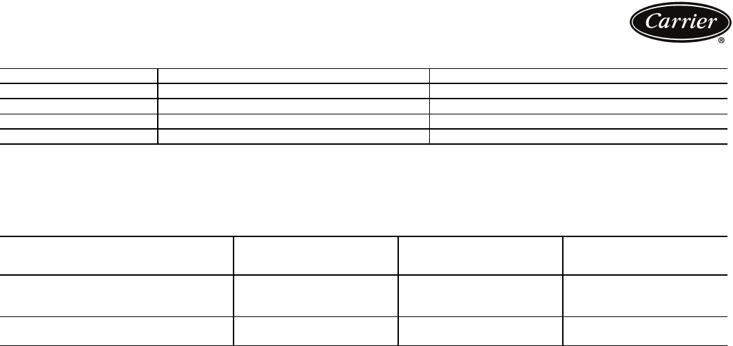
VFD FRAME SIZES
*Maximum limits only. Additional application limits apply that will reduce these ampacities.
AUXILIARY RATINGS*
*Factory wired to VFD.
†Minimum circuit ampacity of 15 amps.
FRAME SIZE MAX INPUT CURRENT*MAX OUTPUT CURRENT*
AA 440 442
BA 520 442
BB 520 520
CC 608608
ITEM VOLTAGE
MAXIMUM
PROTECTIVE DEVICE
SIZE (AMPS)
WATTS
Controls, Oil Pump And Heater Circuit† 115 15 —
Oil Pump 115 1.48130
Oil Sump Heater 115 4.35 500
Oil Vaporizer Heater Circuit† 115 15 —
Oil Vaporizer Heater 115 13 1500
Electrical data

11
Microprocessor controls
Microprocessor controls provide the safety, interlock, ca-
pacity control, indications and accessibility necessary to
operate the chiller in a safe and efficient manner.
Control system
The microprocessor control on each Carrier chiller is
factory-mounted, factory-wired, and factory-tested to
ensure machine protection and efficient capacity control.
In addition, the program logic ensures proper starting,
stopping, and recycling of the chiller and provides a com-
munication link to the Carrier Comfort Network® (CCN)
system.
Features
Control system
• Component test and diagnostic check
• Programmable recycle allows chiller to recycle at opti-
mum loads for decreased operating costs
• Menu-driven keypad interface for status display, set
point control, and system configuration
• CCN system compatible
• Primary and secondary status messages
• Individual start/stop schedules for local and CCN opera-
tion modes
• Recall of up to 25 alarm messages and 25 alert mes-
sages with diagnostic help
• Two chiller lead/lag with third chiller standby is stan-
dard in the PIC III software
• Optional soft stop unloading decreases compressor
speed to unload the motor to the configured amperage
level prior to stopping
• Languages pre-programmed at factory for English, Chi-
nese, Japanese, Korean
• ILT (International Language Translator) available for
conversion of extended ASCII characters
Safety cutouts
• Motor high temperature*†
• Refrigerant (condenser) high pressure*†
• Refrigerant (cooler) low temperature*†
• Lube oil low pressure*
• Compressor (refrigerant) high discharge temperature*
• Under voltage**
• Over voltage**
• Cooler and condenser liquid flow
• Motor overload†
• Motor acceleration time
• Intermittent power loss**
• Motor stall protection
• Low level ground fault
• Cooler and condenser freeze prevention*
• Low oil temperature
• Line voltage imbalance**
• Line current imbalance**
• Line frequency
• Motor current imbalance
• Motor rotation reversal
• Excessive motor amps
• Motor starts limit
• VFD speed out of range
• High VFD rectifier temperature*†
• High VFD inverter temperature*†
• DC bus voltage (Low/High)
Capacity control
• Leaving chilled liquid control
• Entering chilled liquid control
• Soft loading control by temperature or load ramping
• Hot gas bypass valve (optional)
• Power (demand) limiter
• Automatic chilled liquid reset (3 methods)
• Manual speed control
Interlocks
• Manual/automatic remote start
• Starting/stopping sequence
Pre-lube/post-lube
Pre-flow/post-flow
• Compressor run interlock
• Pre-start check of safeties and alerts
• Low chilled liquid (load) recycle
• Monitor/number compressor starts and run hours
• Manual reset of safeties
Indications
• Chiller operating status message
•Power-on
• Pre-start diagnostic check
• Compressor motor amps
• Alert (pre-alarm)††
• Alarm
• Contact for remote alarm
• Safety shutdown messages
• Elapsed time (hours of operation)
• Chiller input kW
• Demand kW
Drive control parameters
• Compressor 100% speed (Hz)
• Rated line voltage
• Rated line amps
• Rated line kW
• Motor rated Load kW
• Motor rated Load amps
• Motor nameplate amps
• Motor nameplate RPM
• Motor nameplate kW
• Inverter PWM frequency
*Can be configured by the user to provide alert indication
at user-defined limit.
†Override protection: Causes compressor to first unload
and then, if necessary, shut down.
**Will not require manual reset or cause an alarm if auto-
restart after power failure is enabled.
††By display code only.
Controls
12
Controls (cont)
CONTROL PANEL DISPLAY (Front View)
ICVC ENGLISH DISPLAY IN SI UNITS
CONTROL PANEL DISPLAY (Front View)
ICVC CHINESE DISPLAY IN METRIC UNITS
13
BLACK
WHITE
RED
BLACK
WHITE
RED
DRAIN WIREDRAIN WIRE
BLACK
WHITE
RED
BLACK
WHITE
RED
DRAIN WIRE
GROUNDDRAIN WIRE
NOTE: Field-supplied terminal strip must be located in control panel.
LEGEND
CCM — Chiller Control Module
Factory Wiring
Field Wiring
CCN COMMUNICATION WIRING FOR MULTIPLE CHILLERS (TYPICAL)
a23-1649
14
Control sequence
To start — Local start-up (manual start-up) is initiated by
pressing the LOCAL or CCN menu softkey, which is indi-
cated on the default international chiller visual control
(ICVC) screen. Time schedule 01 or 03, respectively, must
be in the Occupied mode and the internal 15-minute start-
to-start and the 1-minute stop-to-start inhibit timers must
have expired. All pre-start safeties are checked to verify
that all prestart alerts and safeties are within limits (if one is
not, an indication of the fault displays and the start will be
delayed or is aborted). The signal is sent to start the cooler
liquid pump. Five seconds later, the condenser liquid pump
is energized. If satisfied, it checks the chilled liquid temper-
ature against the control point. If the temperature is less
than or equal to the chilled liquid control point, the con-
denser liquid pump is deenergized and the chiller goes into
a recycle mode.
If the chilled liquid temperature is high enough, the start-
up sequence continues. The oil pump is started and waits a
minimum of 45 sec to verify oil flow. Once oil flow is veri-
fied, the VFD is energized. The control will monitor for a
phase reversal condition. At this time, the following occurs:
• The “start-to-stop” timer is activated.
• The “compressor on-time” and “service on-time” timers
are activated.
• The “starts in 12-hour counter” advances by one.
• The “total compressor starts counter” advances by one.
Once started — If the VFD average current >5% within
15 seconds after VFD start, the machine enters run mode
and speed will be ramped up to meet VFD target speed.
Once the target speed is met the controls, enter the capac-
ity control mode.
Shutdown sequence — The chiller shutdown is initiated
if any of the following occur:
• The Stop button is pressed for at least one second (the
alarm light blinks once to confirm the stop command).
• A recycle shutdown is initiated.
• The time schedule has gone into unoccupied mode.
• The chiller protective limit has been reached and the
chiller is in alarm.
• The start/stop status is overridden to stop from the
ICVC, CCN system, or building management system.
Once the controls shutdown sequence is initiated, the
compressor is stopped and the VFD target speed is set to 0.
If optional soft stop unloading is activated when the Stop
button is pressed or the remote contacts open, motor
speed decreases to a configured amperage level, and the
compressor is stopped. The display indicates “Shutdown in
Progress” while the motor speed decreases. Compressor
ontime and service ontime timers stop once the current in
all phases is <5%, indicating a VFD Stop Complete. The oil
pump and cooler liquid pump are then deenergized. The
condenser liquid pump shuts down when the refrigerant
temperature or entering condenser liquid temperature is be-
low pre-established limits. The 3-minute start-to-stop timer
starts.
Restart — Restart is permitted after both inhibit timers
have expired. If shutdown was due to a safety shutdown,
the reset button must be depressed before restarting the
chiller.
Controls (cont)
MACHINE SAFETIES,
EVAPORATOR PUMP
CONDENSER WATER
PUMP
WATER FLOWS
CHILLED WATER
TEMP,
CONTROL
OIL PUMP
OIL PRESSURE
VERIFIED
VDF FAULT TEST
COMPRESSOR, PHASE
REVERSAL,
COMPRESSOR AND
SERVICE ONTIME
1-MINUTE
STOP-T O-STAR T
TIMER (SOFTWARE
VERSION 13)
15-MINUTE
START-TO-START
TIMER
RAMP VDF TO
TARGET SPEED
COMPRESSOR
RUNNING
ABCDEFGHIJ
KLO/A
TIME
TOWER FAN
0 0
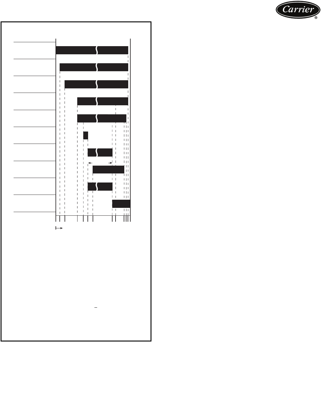
CONTROL SEQUENCE
0—Phase reversal monitored
A—START INITIATED: Pre-start checks are made; evaporator pump
started
B—Condenser liquid pump started (5 seconds after A); tower fan control
enabled
C—Liquid flows verified (30 sec to 5 minutes maximum after B)
D—Chilled liquid temperature checked against control point; oil pump
on.
E—Oil pressure verified (oil pressure verified 45-300 sec after D).
F—VFD starts; phase reversal conditions monitored; compressor
ontime and service ontime start; 15-minute inhibit timer starts (VFD
fault tests for 15 sec after F)
G—Verify average current >5% within 15 sec after VFD start, ramp to
VFD target speed.
H—Compressor reaches target speed, chiller set to running status
I—Shutdown initiated: Target VFD speed to 0% (or J occurs)
J—Ramp down until percent line current < soft stop amps threshold
(0-60 sec after I)
K—Oil pump relay off (1-20 sec after J)
L—Evaporator pump deenergized (60 sec after K); condenser pump
and tower fan control may continue to operate if condenser pressure
is high; evaporator pump may continue if in RECYCLE mode
O/A — Restart permitted (both inhibit timers expired) (minimum of 15 min-
utes after F; minimum of 3 minutes after L)
15
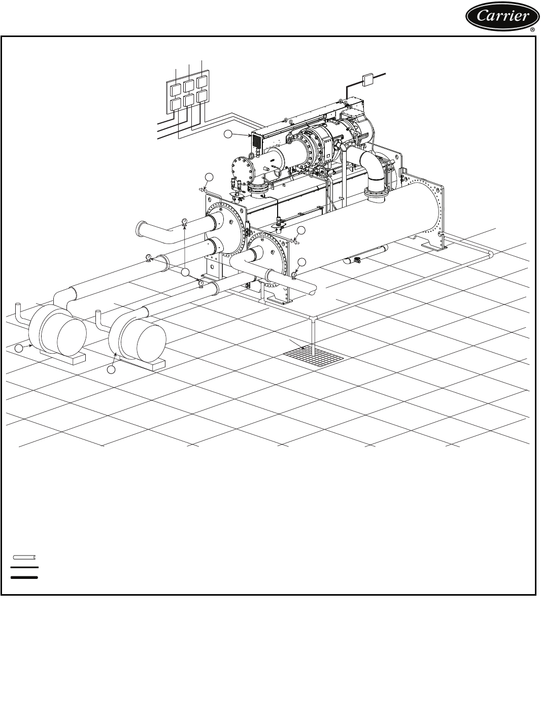
Typical piping and wiring
111
6
7
8
TO CHILLED LIQUID PUMP
TO CONDENSER LIQUID PUMP
TO COOLING TOWER FAN 2
1
MAIN COMPRESSOR
MOTOR POWER
FROM
COOLING
TOWER FROM
LOAD
TO
COOLING
TOWER
TO
LOAD
3
3
9
9
DRAIN
5
4
LEGEND
1—Disconnect
2—Unit-Mounted VFD/Control Center
3—Pressure Gages
4—Chilled Liquid Pump
5—Condenser Liquid Pump
6—Chilled Liquid Pump Starter
7—Condenser Liquid Pump Starter
8—Cooling Tower Fan Starter
9—Vents
Piping
Control Wiring
Power Wiring
NOTES:
1. Wiring and piping shown are for general point-of-connection only and are not
intended to show details for a specific installation. Certified field wiring and
dimensional diagrams are available on request.
2. All wiring must comply with applicable codes.
3. Refer to Carrier System Design Manual for details regarding piping techniques.
4. Wiring not shown for optional devices such as:
• remote start/stop
• remote alarms
• optional safety device
• 4 to 20 mA resets
• optional remote sensors
• kW output
• head pressure reference
5. Flow switches are NOT required.
23XRV CHILLER

16
Control wiring schematic
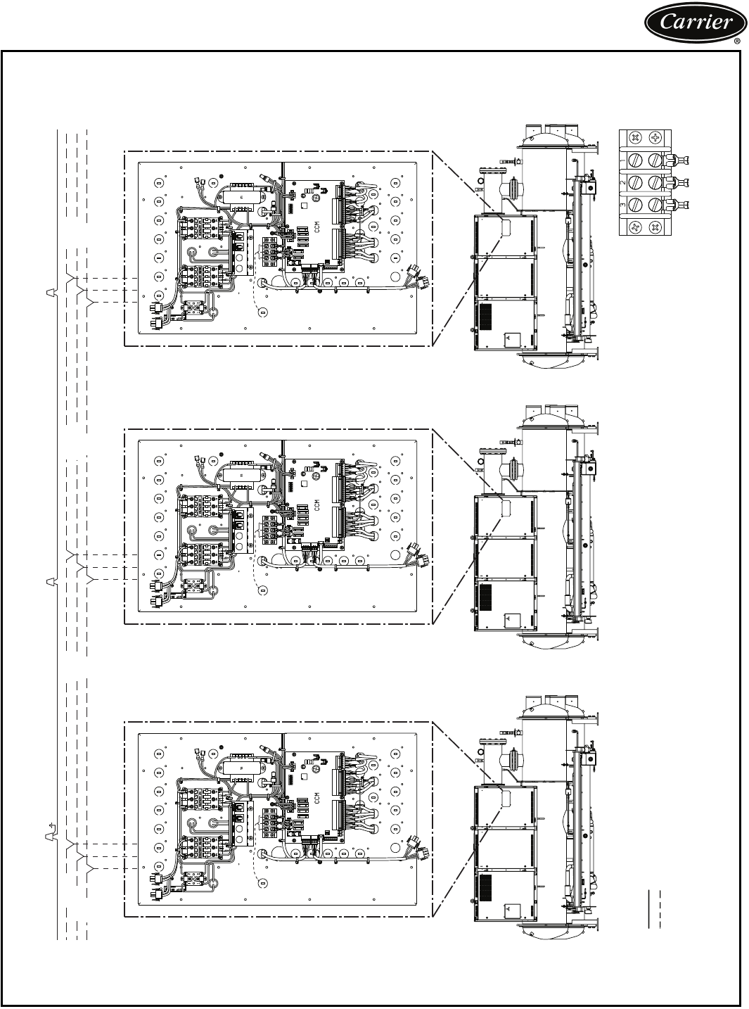
23XRV COMPONENT ARRANGEMENT
LEGEND
CCM — Chiller Control Module
CCN — Carrier Comfort Network®
ICVC — International Chiller Visual Controller
GND — Ground
17
Application data
F
E
YY*
B
G
A
VESSELS
TYP.
0’-3”
[76.2mm]
ACCESSORY
SOLEPLATE
0’-01/2”
[13mm]
TYP.
XX*
VESSELS
COND.
COOLER
C
L
C
L
C
L
C
D
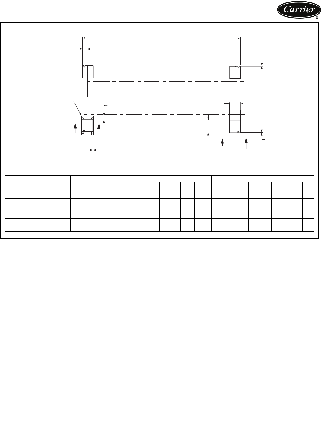
23XRV MACHINE FOOTPRINT
*See detail on page 18.
23XRV
HEAT EXCHANGER
SIZE
DIMENSIONS (ft-in.) DIMENSIONS (mm)
A BCDEFGABCDEFG
30-32 12-103/45-41/4 0 0-35/81-13/40-9 0-1/23931 1632 0 92 349 229 13
35-37 14- 71/45-41/4 0 0-35/81-13/40-9 0-1/24451 1632 0 92 349 229 13
40-42 12-103/46-0 0-11/20-35/81-13/40-9 0-1/23931 1829 3892 349 229 13
45-47 14- 71/46-0 0-11/20-35/81-13/40-9 0-1/24451 1829 3892 349 229 13
50-52 12-103/46-51/20- 1/20-35/81-13/40-9 0-1/23931 1969 13 92 349 229 13
55-57 14- 71/46-51/20- 1/20-35/81-13/40-9 0-1/24451 1969 13 92 349 229 13
a23-1650
910
18
Application data (cont)
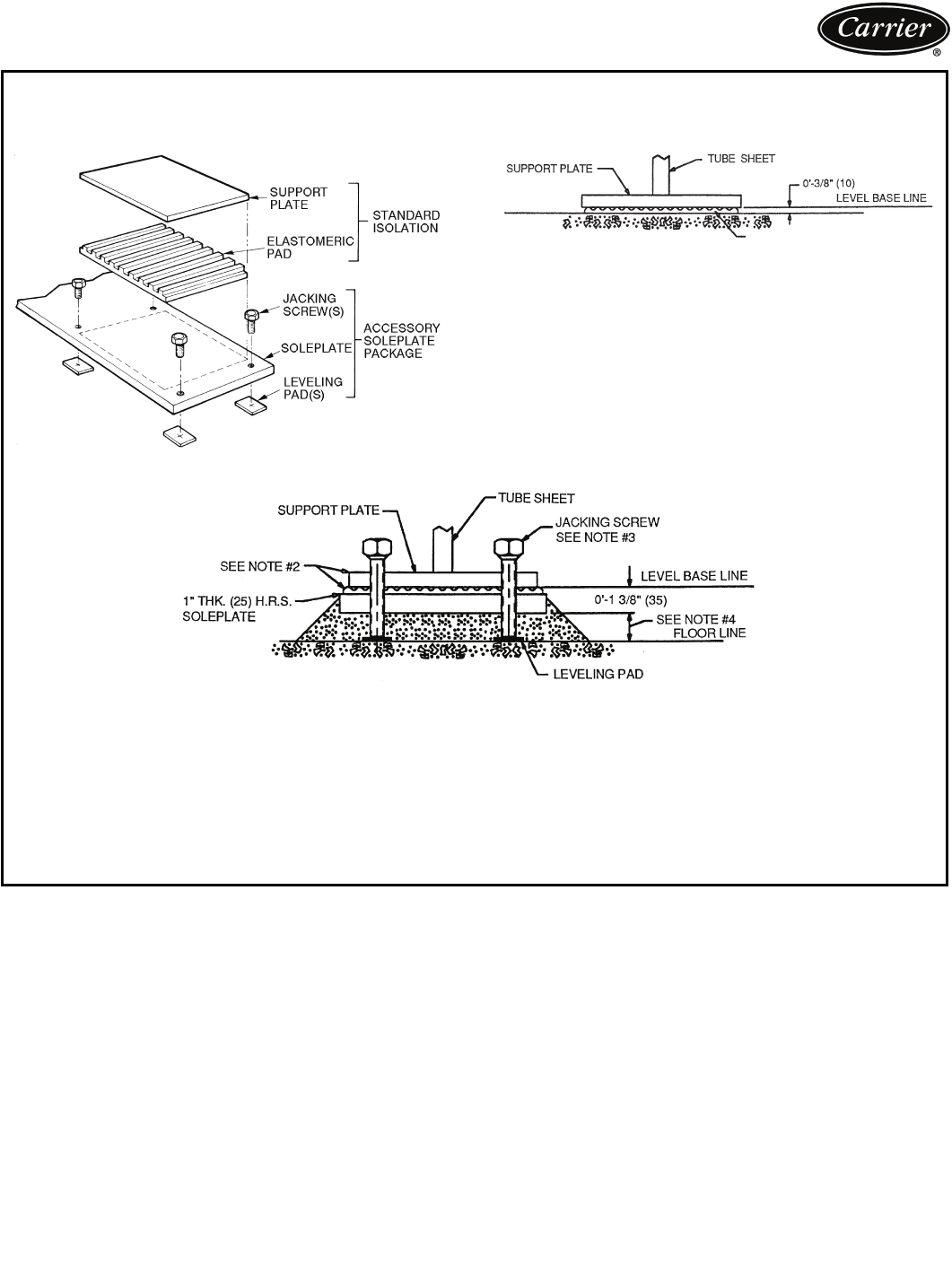
ELASTOMERIC PAD
23XRV ISOLATION WITH ACCESSORY SOLEPLATE PACKAGE
TYPICAL ISOLATION STANDARD ISOLATION
ACCESSORY SOLEPLATE DETAIL
VIEW X-X
NOTES:
1. Dimensions in ( ) are in millimeters.
2. Accessory soleplate package includes 4 soleplates, 16 jacking screws and leveling
pads. Requires isolation package.
3. Jacking screws to be removed after grout has set.
4. Thickness of grout will vary, depending on the amount necessary to level chiller. Use
only pre-mixed non-shrinking grout, Ceilcote 748 or Chemrex Embeco 636 Plus
Grout, 0-11/2 (38.1) to 0-21/4 (57) thick.
5. Service clearance under the chiller is enhanced if leveling pads are not extended
along the entire length of the heat exchangers.
VIEW Y-Y
ISOLATION WITH ISO L AT IO N PAC K A G E O N LY
(STA N DA R D )
NOTE: Isolation package includes 4 elastomeric pads.
a23-1647
19
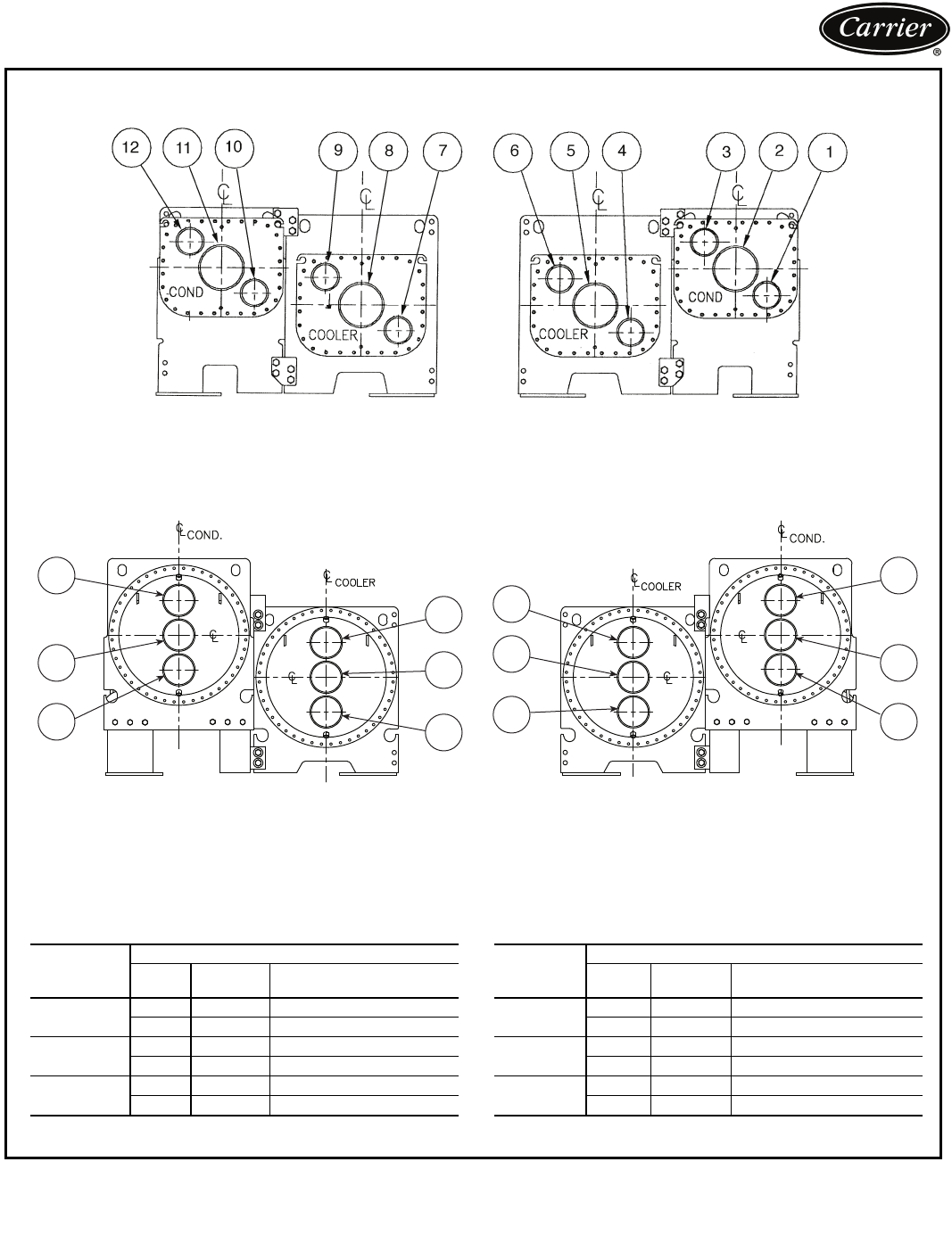
12
11
10
9
8
7
6
5
4
3
2
1
23XRV NOZZLE ARRANGEMENTS
NOZZLE-IN-HEAD WATERBOXES
FRAME 3
FRAMES 4 AND 5
NOZZLE ARRANGEMENT CODES FOR ALL 23XRV NOZZLE-IN-HEAD WATERBOXES
*Refer to certified drawings.
PASS
COOLER WATERBOXES
In Out Arrangement
Code*
185A
58B
279 C
46 D
376 E
49 F
PAS S
CONDENSER WATERBOXES
In Out Arrangement
Code*
111 2 P
211 Q
210 12 R
13 S
310 3 T
112 U
DISCHARGE END SUCTION END
DISCHARGE END SUCTION END
20
Application data (cont)
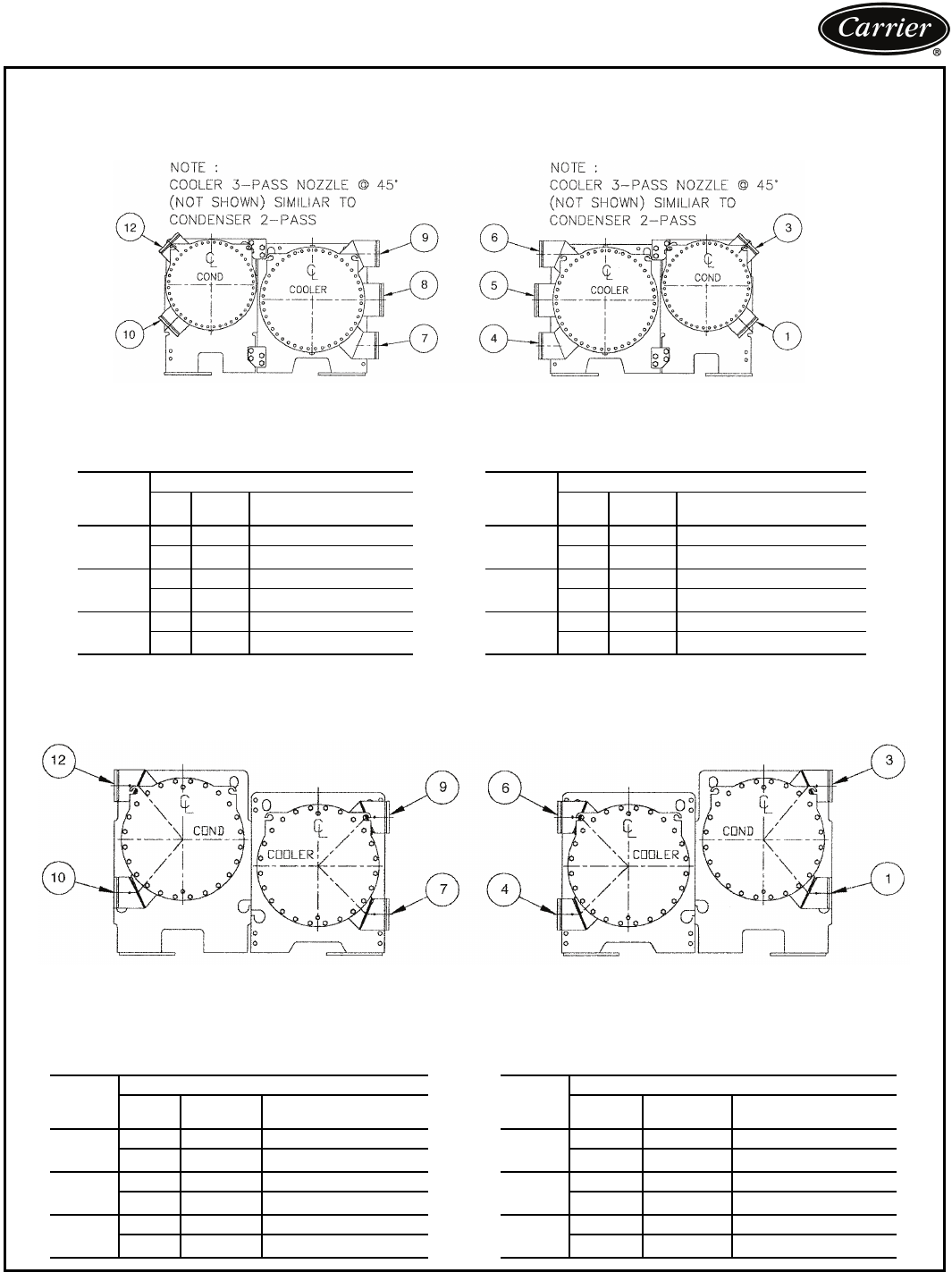
23XRV NOZZLE ARRANGEMENTS (cont)
MARINE WATERBOXES
FRAME 3
NOZZLE ARRANGEMENT CODES
PASS
COOLER WATERBOXES
PASS
CONDENSER WATERBOXES
In Out Arrangement
Code In Out Arrangement
Code
1
85A 1—— —
58B———
279 C 210 12 R
46 D 1 3 S
376 E 3—— —
49 F — — —
FRAMES 4, AND 5
NOZZLE ARRANGEMENT CODES
PAS S
COOLER WATERBOXES
PASS
CONDENSER WATERBOXES
In Out Arrangement
Code In Out Arrangement
Code
196 A 1—— —
69 B — — —
279 C 210 12 R
46 D 1 3 S
376 E 3—— —
49 F — — —
DISCHARGE END SUCTION END
DISCHARGE END SUCTION END
21
23XRV WATERBOX NOZZLE SIZES (Nozzle-In-Head and Marine Waterboxes
RELIEF VALVE LOCATIONS
* Coolers without optional isolation require 2 relief valves.
NOTE: All valves relieve at 185 psig (1275 kPa).
FRAME
SIZE
PRESSURE
psig (kPa) PASS NOMINAL PIPE SIZE (in.) ACTUAL PIPE ID (in.)
Cooler Condenser Cooler Condenser
3150/300
(1034/2068)
1 10 10 10.020 10.020
2887.9817.981
3 6 6 6.065 6.065
4150/300
(1034/2068)
1 10 10 10.020 10.020
2887.9817.981
3 6 6 6.065 6.065
5150/300
(1034/2068)
1 10 10 10.020 10.020
2810 7.981 10.020
36 86.065 7.981
LOCATION FRAME
SIZE
RELIEF VALVE
OUTLET SIZE QUANTITY
MUFFLER 3-5 11/4-in. NPT FEMALE CONNECTOR 1
COOLER 3-5 11/4-in. NPT FEMALE CONNECTOR 1 or 2*
CONDENSER 3-5 11/4-in. NPT FEMALE CONNECTOR 2
OPTIONAL
STORAGE TANK N/A 1-in. NPT FEMALE CONNECTOR 2
WITH OPTIONAL ISOLATION OF DISCHARGE AND COOLER
WITH OPTIONAL ISOLATION WITHOUT OPTIONAL ISOLATION
RELIEF VALVE ARRANGEMENTS
22
Vent and drain connections
Nozzle-in-head waterboxes have vent and drain connec-
tions on covers. Marine waterboxes have vent and drain
connections on waterbox shells.
Provide high points of the chiller piping system with vents
and the low points with drains. If shutoff valves are provid-
ed in the main liquid pipes near the unit, a minimal amount
of system liquid is lost when the heat exchangers are
drained. This reduces the time required for drainage and
saves on the cost of re-treating the system liquid.
It is recommended that pressure gages be provided at
points of entering and leaving liquid to measure pressure
drop through the heat exchanger. Gages may be installed
as shown in Pressure Gage Location table. Pressure gages
installed at the vent and drain connections do not include
nozzle pressure losses.
Use a reliable differential pressure gage to measure pres-
sure differential when determining liquid flow. Regular gag-
es of the required pressure range do not have the accuracy
to provide accurate measurement of flow conditions.
PRESSURE GAGE LOCATION
ASME stamping
All 23XRV heat exchangers are constructed in accordance
with ASHRAE (American Society of Heating, Refrigerat-
ing, and Air Conditioning Engineers) 15 Safety Code for
Mechanical Refrigeration (latest edition). This code, in
turn, requires conformance with ASME (American Society
of Mechanical Engineers) Code for Unfired Pressure Ves-
sels wherever applicable.
Each heat exchanger and economizer (if equipped) is
ASME ‘U’ stamped on the refrigerant side of each vessel.
Relief valve discharge pipe sizing
See page 21 for number of relief valves.
Relief valve discharge piping size should be calculated
per the current version of the ASHRAE 15, latest edition,
code using the tabulated C factors for each vessel shown in
the table below.
23XRV RELIEF VALVE DISCHARGE PIPE SIZING
Carrier further recommends that an oxygen sensor be
installed to protect personnel. Sensor should be able to
sense the depletion or displacement of oxygen in the ma-
chine room below 19.5% volume oxygen per ASHRAE
15, latest edition.
Design pressures
Design and test pressures for heat exchangers are listed
below.
DESIGN AND TEST PRESSURES (23XRV)
*Nitrogen/Helium.
HEAT EXCHANGER MATERIAL SPECIFICATIONS
LEGEND
NUMBER
OF
PASSES
GAGE LOCATION
(Cooler or Condenser)
1 or 3 One gage in each waterbox
2Two gages in waterbox with nozzles
HEAT
EXCHANGER
FRAME
SIZE
VESSEL
REQUIRED
C FACTOR
(lb air/Min)
RELIEF
VALVE
RATED
C FACTOR
(lb air/Min)
FIELD
CONNECTION
SIZE (FPT)
COOLER
30 to 32 43.4 70.811/4
35 to 37 49.5 70.811/4
40 to 42 50.4 70.811/4
45 to 47 57.4 70.811/4
50 to 52 53.7 70.811/4
55 to 57 61.1 70.811/4
CONDENSER
30 to 32 41.4 70.811/4
35 to 37 47.1 70.811/4
40 to 42 47.1 70.811/4
45 to 47 53.7 70.811/4
50 to 52 51.2 70.811/4
55 to 57 58.3 70.811/4
PRESSURES
SHELL SIDE
(Refrigerant)
STANDARD TUBE SIDE
(Liquid)
OPTIONAL TUBE SIDE
(Liquid)
psig kPa psig kPa psig kPa
Leak Test at Design Pressure*185 1276 150 1034 300 2068
Hydrostatic — — 195 1344 390 2689
Proof Test*204 1407 — — — —
ITEM MATERIAL SPECIFICATION
Shell HR Steel ASME SA516 GR 70
Tube Sheet HR Steel ASME SA516 GR 70
Condenser/Cooler Waterbox Cover HR Steel ASME SA516 GR 70, SA-36, or SA-285 GRC
Condenser/Cooler Waterbox Shell HR Steel ASME SA675 GR 60, SA-516 GR70, or SA-181 CL70,
SA-36, SA-675 GR70, SAE AME 7496
Tube s Finned Copper ASME SB359
Discharge/Suction
Pipe Steel ASME SA106 GRB
Flanges Steel ASME SA105
ASME — American Society of Mechanical Engineers
HR — Hot Rolled
Application data (cont)
23
Insulation
23XRV MINIMUM FIELD-INSTALLED INSULATION
REQUIREMENTS
Factory insulation — Thermal insulation is factory-
provided to the following areas:
• Cooler (not including waterbox)
• Suction line
• Compressor and motor
• Oil cooling line and oil return system line (oil and refrig-
erant lines at or near evaporator pressure are insulated)
• VFD cooling line (oil and refrigerant lines at or near
evaporator pressure are insulated)
• Motor cooling line
• Vaporizer
• Liquid line and discharge line
• Float chamber
• Optional economizer (including vent line and econo-
mizer muffler)
Factory insulation is not available for the waterboxes.
Insulation applied at the factory is 1/2-in. (13 mm) thick
closed cell and 1/2-in. (13 mm) open cell PVC-Nitrile foam.
Some parts of the chiller are also treated with an outer
layer of 3/16-in. (5 mm) thick vinyl. The 1/2-in. (13 mm)
closed cell foam has a thermal conductivity K value of
0.28 (BTU in.)/(hr sqft °F) [0.0404 W/(m °C)] and
conforms with Underwriters Laboratories (UL) Standard
94, Classification 94 HF-1. Both the 1/2-in. foam and the
3/16-in. vinyl layer will pass flammability test method
MVSS 302.
Field insulation — As indicated in the Condensation vs
Relative Humidity table, the factory insulation provides
excellent protection against condensation under most op-
erating conditions. If temperatures in the equipment area
exceed the maximum design conditions, extra insulation is
recommended.
If the machine is to be field insulated, obtain the approx-
imate areas from the 23XRV Minimum Field-Installed Insu-
lation Requirements table.
Insulation of waterbox is made only in the field and this
area is not included in 23XRV Minimum Field-Installed In-
sulation Requirements table. When insulating the covers,
allow for service access and removal of covers. To estimate
water-box cover areas, refer to certified drawings.
High humidity jobsite locations may require field sup-
plied and installed insulation on the float chamber, suction
housing, and the lower half of the condenser.
CONDENSATION VS RELATIVE HUMIDITY*
*These approximate figures are based on 35 F (1.7 C) saturated suction
temperature. A 2° F (1.1° C) change in saturated suction temperature
changes the relative humidity values by 1% in the same direction.
Minimum fluid loop volume
Minimum fluid volume must be in excess of 1.5 gal per ton
(20 L per kW) for comfort cooling applications and apply 3
to 5 gal per ton (40 to 66 L per kW) fluid loop volume for
process applications.
COMPONENT SIZE INSULATION
ft2m2
Cooler
30-32 96 8.9
35-37 10810.0
40-42 109 10.1
45-47 122 11.3
50-52 115 10.7
55-57 130 12.1
Misc. Liquid Lines All Sizes 21 2.0
Economizer All Sizes 20 1.9
Compressor Motor All Sizes 17 1.6
AMOUNT OF
CONDENSATION
ROOM DRY-BULB TEMPERATURE
80 F (27 C) 90 F (32 C) 100 F (38 C)
% Relative Humidity
None 8076 70
Slight 878477
Extensive 94 91 84
910

24
Variable Speed Screw Chiller
HVAC Guide Specifications
Size Range: 300 to 550 Tons (1055 to 1934 kW)
Nominal
Carrier Model Number: 23XRV
Part 1 — General
1.01 SYSTEM DESCRIPTION
A. Microprocessor-controlled liquid chiller shall use a
semi-hermetic screw compressor using refrigerant
HFC-134a only. Chiller refrigerant shall not have a
planned phase out date.
B. If a manufacturer proposes a liquid chiller using
HCFC-123 refrigerant, which has a planned phase
out date, then the manufacturer shall include in the
chiller price:
1. A vapor activated alarm system consisting of all
alarms, sensors, safeties, and ventilation equip-
ment as required by ANSI/ASHRAE Standard
15 Safety Code for Mechanical Refrigeration
(latest edition) with the quotation. System shall
be capable of responding to HCFC-123 levels
of 10 ppm Allowable Exposure Limit (AEL).
2. A free-standing refrigerant storage tank and
pumpout unit shall be provided. The storage
vessels shall be designed per ASME Section VIII
Division 1 code with 300 psig (2068 kPa)
design pressure. Double relief valves per ANSI/
ASHRAE 15, latest edition, shall be provided.
The tank shall include a liquid level gage and
pressure gage. The pumpout unit shall use a
semi-hermetic reciprocating compressor with
water cooled condenser. Condenser water pip-
ing, 3-phase motor power, and 115-volt control
power shall be installed at the jobsite by the
installing contractor.
3. Zero emission purge unit capable of operating
even when the chiller is not operating.
4. Back-up relief valve to rupture disk.
5. Factory-installed chiller pressurizing system to
prevent leakage of noncondensables into the
chiller during shutdown periods.
6. Plant room ventilation.
7. Removal and disposal of refrigerant at the end
of the phase out period.
8. Chillers utilizing a purge unit shall include in the
machine price the costs to perform the follow-
ing regular maintenance procedures:
a. Weekly: Check refrigerant charge.
b. Quarterly: Charge purge unit dehydrator at
least quarterly, more often if necessary.
Clean foul gas strainer. Perform chemical
analysis of oil.
c. Annually: Clean and inspect all valves. Drain
and flush purge shell. Clean orifices.
1.02 QUALITY ASSURANCE
A. Chiller performance shall be rated in accordance
with AHRI Standard 550/590, latest edition.
B. Equipment and installation shall be in compliance
with ANSI/ASHRAE 15 (latest edition).
C. Cooler and condenser refrigerant side shall include
ASME “U” stamp and nameplate certifying compli-
ance with ASME Section VIII, Division 1 code for
unfired pressure vessels.
D. A manufacturer’s data report is required to verify
pressure vessel construction adherence to ASME
vessel construction requirements. Form U-1 as
required per ASME code rules is to be furnished
to the owner. The U-1 Form must be signed by a
qualified inspector, holding a National Board
Commission, certifying that construction conforms
to the latest ASME Code Section VIII, Div. 1 for
pressure vessels. The ASME symbol “U” must also
be stamped on the heat exchanger. Vessels specifi-
cally exempted from the scope of the code must
come with material, test, and construction methods
certification and detailed documents similar to
ASME U-1; further, these must be signed by an offi-
cer of the company.
E. Chiller shall be designed and constructed to meet
UL and UL of Canada requirements and have labels
appropriately affixed.
F. Unit shall be manufactured in a facility registered to
ISO 9001:2000 Manufacturing Quality Standard.
G. Each compressor assembly shall undergo a mechan-
ical run-in test to verify vibration levels, oil pressures,
and temperatures are within acceptable limits. Each
compressor assembly shall be proof tested at a mini-
mum 204 psig (1407 kPa) and leak tested at
185 psig (1276 kPa) with a tracer gas mixture.
H. Entire chiller assembly shall be proof tested at
204 psig (1407 kPa) and leak tested at 185 psig
(1276 kPa) with a tracer gas mixture on the refriger-
ant side. The leak test shall not allow any leaks
greater than 0.5 oz per year of refrigerant. The
water side of each heat exchanger shall be hydro-
statically tested at 1.3 times rated working pressure.
I. Prior to shipment, the chiller automated controls
test shall be executed to check for proper wiring and
ensure correct controls operation.
J. Chillers shall have factory-mounted, factory-wired
and factory-tested unit-mounted variable frequency
drive (VFD). Proper VFD operation shall be con-
firmed prior to shipment.
1.03 DELIVERY, STORAGE AND HANDLING
A. Unit shall be stored and handled in accordance with
manufacturer’s instructions.
B. Unit shall be shipped with all refrigerant piping and
control wiring factory-installed.
C. Unit shall be shipped charged with oil and full
charge of refrigerant HFC-134a or a nitrogen hold-
ing charge as specified on the equipment schedule.
Guide specifications

25
D. Unit shall be shipped with firmly attached labels that
indicate name of manufacturer, chiller model num-
ber, chiller serial number, and refrigerant used.
E. If the unit is to be exported, the manufacturer shall
provide sufficient protection against sea water corro-
sion, making the unit suitable for shipment in a
standard open top ocean shipping container.
F. Chiller and starter shall be stored indoors, protected
from construction dirt and moisture. Chiller shall be
inspected under shipping tarps, bags, or crates to be
sure water has not collected during transit. Protec-
tive shipping covers shall be kept in place until
machine is ready for installation. The inside of the
protective cover shall meet the following criteria:
1. Temperature is between 40 F (4.4 C) and
120 F (48.9 C)
2. Relative humidity is between 10% and 80%
non-condensing.
1.04 WARRANTY
Warranty shall include parts and labor for one year
after start-up or 18 months from shipment, which-
ever occurs first. A refrigerant warranty shall be
provided for a period of 5 years.
Part 2 — Products
2.01 EQUIPMENT
A. General:
Factory-assembled, single piece, liquid chiller shall
consist of compressor, motor, VFD, lubrication sys-
tem, cooler, condenser, initial oil and refrigerant
operating charges, microprocessor control system,
and documentation required prior to start-up.
B. Compressor:
1. One variable speed, tri-rotor screw compressor
of the high performance type.
2. Compressor and motor shall be hermetically
sealed into a common assembly and arranged
for easy field servicing.
3. The compressor motor shall be accessible for
servicing without removing the compressor
base from the chiller. Connections to the com-
pressor casing shall use O-rings and gaskets to
reduce the occurrence of refrigerant leakage.
Connections to the compressor shall be flanged
or bolted for easy disassembly.
4. Compressor bearings must have individual
design life of 500,000 hours or greater.
5. Compressor shall provide capacity modulation
from 100% to 15% capacity without the use of
hot gas bypass or mechanical unloaders.
6. Compressor shall be provided with a factory-
installed positive pressure lubrication system to
deliver oil under pressure to bearings and rotors
at all operating conditions. Lubrication system
shall include:
a. Oil pump with factory-installed motor con-
tactor with overload protection.
b. Oil pressure sensor with differential readout
at main control center.
c. Oil pressure regulator.
d. Oil filter with isolation valves to allow filter
change without removal of refrigerant
charge.
e. Oil sump heater [115 v, 50 or 60 Hz] con-
trolled from unit microprocessor.
f. Oil reservoir temperature sensor with main
control center digital readout.
g. All wiring to oil pump, oil heater, and con-
trols shall be pre-wired in the factory and
power shall be applied to check proper
operation prior to shipment.
7. Compressor shall be fully field serviceable.
Compressors that must be removed and
returned to the factory for service shall be
unacceptable.
8. Acoustical attenuation shall be provided as
required, to achieve a maximum (full load
or part load) sound level, measured per AHRI
Standard 575 (latest edition).
C. Motor:
1. Compressor motor shall be of the semi-
hermetic, liquid refrigerant cooled, squirrel
cage, induction type suitable for voltage shown
on the equipment schedule.
2. If an open (air cooled) motor is provided, a
compressor shaft seal leakage containment
system shall be provided:
a. An oil reservoir shall collect oil and refriger-
ant that leaks past the seal.
b. A float device shall be provided to open
when the reservoir is full, directing the
refrigerant/oil mixture back into the com-
pressor housing.
c. A refrigerant sensor shall be located next to
the open drive seal to detect leaks.
3. Motors shall be suitable for operation in a
refrigerant atmosphere and shall be cooled by
atomized refrigerant in contact with the motor
windings.
4. Motor stator shall be arranged for service or
removal with only minor compressor disassem-
bly and without removing main refrigerant
piping connections.
5. Full load operation of the motor shall not
exceed nameplate rating.
6. One motor winding temperature sensor (and on
spare) shall be provided.
7. Should the mechanical contractor choose to
provide a chiller with an air-cooled motor
instead of the specified semi-hermetic motor,
the contractor shall install additional cooling

26
equipment to dissipate the motor heat as per
the following formula:
Btuh = (FLkW motor) (0.05) (3413)
Btuh = (FLkW motor) (171)
and, alternately
Tons = Btuh/12,000
The additional piping, valves, air-handling
equipment, insulation, wiring, switchgear
changes, ductwork, and coordination with other
trades shall be the responsibility of the mechan-
ical contractor. Shop drawings reflecting any
changes to the design shall be included in the
submittal, and incorporated into the final as-
built drawings for the project.
8. Also, if an open motor is provided, a mechani-
cal room thermostat shall be provided and set
at 104 F (40 C). If this temperature is
exceeded, the chillers shall shut down and an
alarm signal shall be generated to the central
Energy Management System (EMS) display
module, prompting the service personnel to
diagnose and repair the cause of the overtem-
perature condition. The mechanical contractor
shall be responsible for all changes to the
design, including coordination with temperature
control, electrical and other trades. In addition,
the electrical power consumption of any auxil-
iary ventilation and/or mechanical cooling
required to maintain the mechanical room con-
ditions stated above shall be considered in the
determination of conformance to the scheduled
chiller energy efficiency requirement.
D. Unit-Mounted Variable Frequency Drive (VFD) with
Built-In Harmonic LiquiFlo™ II Filter:
The compressor shall be factory-mounted, factory-
wired and factory-tested prior to shipment by the
chiller manufacturer. All interconnecting wiring and
piping between the VFD and the chiller shall be
factory-installed. Customer electrical connection for
compressor motor power shall be limited to main
power leads to the VFD, and wiring liquid pumps
and tower fans to the chiller control circuit. The
VFD shall incorporate the following features:
1. Design:
a. The VFD shall be refrigerant cooled,
microprocessor based, pulse width modu-
lated design. Water cooled designs are not
acceptable.
b. Input and output power devices shall be
Insulated Gate Bipolar Transistors (IGBTs).
c. Rectifier shall convert incoming fixed volt-
age/frequency to fixed DC voltage.
d. Transistorized inverter and control regulator
shall convert fixed DC voltage to a sinusoidal
PWM waveform.
e. Low voltage control sections and main
power sections shall be physically isolated.
f. Integrated controls shall coordinate motor
speed to optimize chiller performance over a
wide variety of operating conditions.
2. Enclosure:
a. Pre-painted unit mounted, NEMA 1 cabinet
shall include hinged, lockable doors and
removable lifting lugs.
b. The VFD shall have a short circuit interrupt
and withstand rating of at least 65,000 amps.
c. Provisions to padlock main disconnect han-
dle in the “Off” positions shall be provided.
Mechanical interlock to prevent opening
cabinet door with disconnect in the “On”
position or moving disconnect to the “On”
position while the door is open shall be
provided.
d. Provisions shall be made for top entry of
incoming line power cables.
3. Heat Sink:
a. The heat sink shall be refrigerant cooled.
Heat sink and mating flanges shall be suit-
able for ASME design working pressure of
185 psig (1276 kPa).
b. Refrigerant cooling shall be metered to
maintain heat sink temperature within
acceptable limits for ambient temperature.
4. VFD Rating:
a. Drive shall be suitable for operation at name-
plate voltage ±10%.
b. Drive shall be suitable for continuous opera-
tion at 100% of nameplate amps and 150%
of nameplate amps for 5 seconds.
c. Drive shall comply with applicable ANSI,
NEMA, UL and NEC standards.
d. Drive shall be suitable for operation in ambient
temperatures between 40 and 122 F (4 and
50 C), 95% humidity (non-condensing) for
altitudes up to 6000 ft (1829 m) above sea
level. Specific drive performance at jobsite
ambient temperature and elevation shall be
provided by the manufacturer in the bid.
5. User Interface:
A single display shall provide interface for pro-
gramming and display of VFD and chiller
parameters. Viewable parameters include:
a. Operating, configuration and fault messages
b. Frequency in hertz
c. Load and line side voltage and current (at the
VFD)
d. kW
e. IGBT temperature
6. VFD Performance:
a. The VFD Voltage Total Harmonic Distortion
(THD) and Harmonic Current Total Demand
Distortion (TDD) shall not exceed IEEE-519
requirements using the VFD circuit breaker
Guide specifications (cont)

27
input terminals as the point of common cou-
pling (PCC).
b. The VFD full load efficiency shall meet or
exceed 97% at 100% VFD rated ampacity.
c. Active rectifier shall regulate unity displace-
ment power factor to 0.99 or higher.
d. Voltage boost capability to provide full motor
voltage at reduced line voltage conditions.
e. The VFD shall feature soft start, linear accel-
eration, and coast to stop capabilities.
f. Base motor frequency shall permit motor to
be utilized at nameplate voltage. Adjustable
frequency range shall permit capacity con-
trol down to 15%.
g. The VFD shall have 150% instantaneous
torque generation.
7. VFD Electrical Service (single point power):
a. The VFD shall have input circuit breaker
with minimum 65,000 amp interrupt
capacity.
b. The VFD shall have standard branch oil
pump circuit breaker to provide power for
chiller oil pump.
c. The VFD shall have standard 3 KVA control
power transformer with circuit breaker to
provide power for oil heater, VFD controls
and chiller controls.
d. The branch oil pump circuit breaker and
control power transformer shall be factory-
wired.
e. Input power shall be 380/460 vac, ±10%,
3 Phase, 50/60 Hz, ±2% Hz.
8. Discrete Outputs:
115-v discrete contact outputs shall be provided
for:
a. Circuit breaker shunt trip
b. Chilled water pump
c. Condenser water pump
d. Alarm status
9. Analog Output:
An analog (4 to 20 mA) output for head pres-
sure reference shall be provided. This signal
shall be suitable to control a 2-way or 3-way
water regulating valve in the condenser piping.
10. Protection (the following shall be supplied):
a. Under-voltage
b. Over voltage
c. Phase loss
d. Phase reversal
e. Ground fault
f. Phase unbalance protection
g. Single cycle voltage loss protection
h. Programmable auto re-start after loss of
power
i. Motor overload protection (NEMA Class 10)
j. Motor over temperature protection
11. VFD Testing:
The VFD shall be factory-mounted, factory-
wired and factory-tested on the chiller prior to
shipment.
E. Evaporator and Condenser:
1. Evaporator and condenser shall be of shell and
tube type construction, each in separate shells.
Units shall be fabricated with high-performance
tubing, steel shell and tube sheets with fabri-
cated steel waterboxes. Waterboxes shall be
nozzle-in-head type with stub out nozzles having
Victaulic grooves to allow for use of Victaulic
couplings.
2. Tubing shall be copper, high-efficiency type,
with integral internal and external enhance-
ment unless otherwise noted. Tubes shall be
nominal 3/4-in. OD with nominal wall thickness
of 0.025 in. measured at the root of the fin
unless otherwise noted. Tubes shall be rolled
into tube sheets and shall be individually
replaceable. Tube sheet holes shall be double
grooved for joint structural integrity. Intermedi-
ate support sheet spacing shall not exceed
36 in. (914 mm).
3. Waterboxes and nozzle connections shall be
designed for 150 psig (1034 kPa) minimum
working pressure unless otherwise noted.
Nozzles should have grooves to allow use of
Victaulic couplings.
4. The tube sheets of the cooler and condenser
shall be bolted together to allow for field disas-
sembly and reassembly.
5. The vessel shall display an ASME nameplate
that shows the pressure and temperature data
and the “U” stamp for ASME Section VIII,
Division 1. A re-seating pressure relief valve(s)
shall be installed on each heat exchanger. If a
non-reseating type is used, a backup reseating
type shall be installed in series.
6. Waterboxes shall have vents, drains, and covers
to permit tube cleaning within the space shown
on the drawings. A thermistor type temperature
sensor with quick connects shall be factory-
installed in each water nozzle.
7. Cooler shall be designed to prevent liquid refrig-
erant from entering the compressor. Devices
that introduce pressure losses (such as mist
eliminators) shall not be acceptable because
they are subject to structural failures that can
result in extensive compressor damage.
8. Tubes shall be individually replaceable from
either end of the heat exchanger without affect-
ing the strength and durability of the tube sheet
and without causing leakage in adjacent tubes.
9. The condenser shell shall include a FLASC
(Flash Subcooler) which cools the condensed

28
liquid refrigerant to a reduced temperature,
thereby increasing the refrigeration cycle
efficiency.
F. Refrigerant Flow Control:
To improve part load efficiency, liquid refrigerant
shall be metered from the condenser to the cooler
using a float-type metering valve to maintain the
proper liquid level of refrigerant in the heat
exchangers under both full and part load operating
conditions. By maintaining a liquid seal at the float
valve, bypassed hot gas from the condenser to the
cooler is eliminated.
G. Controls, Safeties, and Diagnostics:
1. Controls:
a. The chiller shall be provided with a factory-
installed and factory-wired microprocessor
control center. The control center shall include
a 16-line by 40-character liquid crystal display,
4 function keys, stop button, and alarm light.
Other languages are available using the inter-
national language translator software.
b. All chiller and motor control monitoring shall
be displayed at the chiller control panel.
c. The controls shall make use of non-volatile
memory.
d. The chiller control system shall have the ability
to interface and communicate directly to the
building control system.
e. The default standard display screen shall simul-
taneously indicate the following minimum
information:
1) Date and time of day
2) 24-character primary system status
message
3) 24-character secondary status message
4) Chiller operating hours
5) Entering chilled water temperature
6) Leaving chilled water temperature
7) Evaporator refrigerant temperature
8) Entering condenser water temperature
9) Leaving condenser water temperature
10) Condenser refrigerant temperature
11) Oil supply pressure
12) Oil sump temperature
13) Percent motor rated load amps (RLA)
f. In addition to the default screen, status
screens shall be accessible to view the status
of every point monitored by the control
center including:
1) Evaporator pressure
2) Condenser pressure
3) Compressor speed
4) Bearing oil supply temperature
5) Compressor discharge temperature
6) Motor winding temperature
7) Number of compressor starts
8) Control point settings
9) Discrete output status of various devices
10) Variable frequency drive status
11) Optional spare input channels
12) Line current and voltage for each phase
13) Frequency, kW, kWhr, demand kW
g. Schedule Function:
The chiller controls shall be configurable for
manual or automatic start-up and shutdown.
In automatic operation mode, the controls
shall be capable of automatically starting and
stopping the chiller according to a stored
user programmable occupancy schedule.
The controls shall include built-in provisions
for accepting:
1) A minimum of two 365-day occupancy
schedules.
2) Minimum of 8 separate occupied/unoc-
cupied periods per day
3) Daylight savings start/end
4) 18 user-defined holidays
5) Means of configuring an occupancy
timed override
6) Chiller start-up and shutdown via remote
contact closure
h. Service Function:
The controls shall provide a password
protected service function which allows
authorized individuals to view an alarm
history file which shall contain the last
25 alarm/alert messages with time and date
stamp. These messages shall be displayed in
text form, not codes.
i. Network Window Function:
Each chiller control panel shall be capable of
viewing multiple point values and statuses
from other like controls connected on a
common network, including controller main-
tenance data. The operator shall be able to
alter the remote controller’s set points or
time schedule and to force point values or
statuses for those points that are operator
forcible. The control panel shall also have
access to the alarm history file of all like con-
trollers connected on the network.
j. Pump Control:
Upon request to start the compressor, the
control system shall start the chilled and
condenser water pumps and shall verify that
flows have been established.
k. Ramp Loading:
A user-configurable ramp loading rate, effec-
tive during the chilled water temperature
pulldown period, shall prevent a rapid
increase in compressor power consumption.
The controls shall allow configuration of the
ramp loading rate in either degrees per min-
ute of chilled water temperature pulldown or
percent motor amps per minute. During the
ramp loading period, a message shall be
Guide specifications (cont)

29
displayed informing the operator that the
chiller is operating in ramp loading mode.
l. Chilled Water Reset:
The control center shall allow reset of the
chilled water temperature set point based on
any one of the following criteria:
1) Chilled water reset based on an external
4 to 20 mA signal.
2) Chilled water reset based on a remote
temperature sensor (such as outdoor
air).
3) Chilled water reset based on water tem-
perature rise across the evaporator.
m. Demand Limit:
The control center shall limit amp draw of
the compressor to the rated load amps or to
a lower value based on one of the following
criteria:
1) Demand limit based on a user input
ranging from 40% to 100% of compres-
sor rated load amps
2) Demand limit based on external 4 to
20 mA signal.
n. Controlled Compressor Shutdown:
The controls shall be capable of being
configured to soft stop the compressor. The
display shall indicate “shutdown in progress.”
2. Safeties:
a. Unit shall automatically shut down when any
of the following conditions occur (each of
these protective limits shall require manual
reset and cause an alarm message to be dis-
played on the control panel screen, inform-
ing the operator of the shutdown cause):
1) Motor overcurrent
2) Over voltage*
3) Under voltage*
4) Single cycle dropout*
5) Low oil sump temperature
6) Low evaporator refrigerant temperature
7) High condenser pressure
8) High motor temperature
9) High compressor discharge temperature
10) Low oil pressure
11) Prolonged stall
12) Loss of cooler water flow
13) Loss of condenser water flow
14) Variable frequency drive fault
15) High variable frequency drive temperature
* Shall not require manual reset or cause an
alarm if auto-restart after power failure is
enabled.
b. The control system shall detect conditions
that approach protective limits and take self-
corrective action prior to an alarm occur-
ring. The system shall automatically reduce
chiller capacity when any of the following
parameters are outside their normal operat-
ing range:
1) High condenser pressure
2) High motor temperature
3) Low evaporator refrigerant temperature
4) High motor amps
5) High VFD rectifier temperature
6) High VFD inverter temperature
c. During the capacity override period, a pre-
alarm (alert) message shall be displayed
informing the operator which condition is
causing the capacity override. Once the con-
dition is again within acceptable limits, the
override condition shall be terminated and
the chiller shall revert to normal chilled
water control. If during either condition the
protective limit is reached, the chiller shall
shut down and a message shall be displayed
informing the operator which condition
caused the shutdown and alarm.
d. Internal built in safeties shall protect the
chiller from loss of water flow. Differential
pressure switches shall not be allowed to be
the only form of freeze protection.
3. Diagnostics and Service:
a. A self diagnostic controls test shall be an
integral part of the control system to allow
quick identification of malfunctioning
components.
b. Once the controls test has been initiated, all
pressure and temperature sensors shall be
checked to ensure they are within normal
operating range. A pump test shall automat-
ically energize the chilled water pump, con-
denser water pump, and oil pump. The
control system shall confirm that water flow
and oil pressure have been established and
require operator confirmation before pro-
ceeding to the next test.
c. In addition to the automated controls test,
the controls shall provide a manual test
which permits selection and testing of indi-
vidual control components and inputs. A
thermistor test and transducer test shall dis-
play on the ICVC screen the actual reading
of each transducer and each thermistor
installed on the chiller. All out-of-range sen-
sors shall be identified. Pressure transducers
shall be serviceable without the need for
refrigerant charge removal or isolation.
4. Multiple Chiller Control:
The chiller controls shall be supplied as stan-
dard with a two-chiller lead/lag and a third
chiller standby system. The control system shall
automatically start and stop a lag or second
chiller on a two-chiller system. If one of the two
chillers on line goes into a fault mode, the third
standby chiller shall be automatically started.
The two-chiller lead/lag system shall allow

30
manual rotation of the lead chiller and a stag-
gered restart of the chillers after a power fail-
ure. The lead/lag system shall include load
balancing if configured to do so.
H. Electrical Requirements:
1. Electrical contractor shall supply and install
main electrical power line, disconnect switches,
circuit breakers, and electrical protection
devices per local code requirements and as indi-
cated necessary by the chiller manufacturer.
2. Electrical contractor shall wire the chilled water
pump and flow, condenser water pump and
flow, and tower fan control circuit to the chiller
control circuit.
3. Electrical contractor shall supply and install
electrical wiring and devices required to inter-
face the chiller controls with the building control
system if applicable.
4. Electrical power shall be supplied to the unit at
the voltage, phase, and frequency listed in the
equipment schedule.
I. Piping Requirements — Instrumentation and Safeties:
1. Mechanical contractor shall supply and install
pressure gages in readily accessible locations in
piping adjacent to the chiller such that they can
be easily read from a standing position on the
floor. Scale range shall be such that design val-
ues shall be indicated at approximately mid-
scale.
2. Gages shall be installed in the entering and leav-
ing water lines of the cooler and condenser.
J. Vibration Isolation:
Chiller manufacturer shall furnish neoprene isolator
pads for mounting equipment on a level concrete
surface.
K. Start-Up:
1. The chiller manufacturer shall provide a factory-
trained representative, employed by the chiller
manufacturer, to perform the start-up proce-
dures as outlined in the Start-Up, Operation
and Maintenance manual provided by the
chiller manufacturer.
2. Manufacturer shall supply the following
literature:
a. Start-up, operation and maintenance
instructions.
b. Installation instructions.
c. Field wiring diagrams.
d. One complete set of certified drawings.
L. Special Features:
1. Soleplate Package:
Unit manufacturer shall furnish a soleplate
package consisting of soleplates, jacking
screws, leveling pads, and neoprene pads.
2. Spring Isolators:
Spring isolators shall be field furnished and
selected for the desired degree of isolation.
3. Spare Sensors with Leads:
Unit manufacturer shall furnish additional tem-
perature sensors and leads.
4. Sound Insulation Kit:
Unit manufacturer shall furnish a sound insula-
tion kit that covers the compressor housing,
motor housing, compressor discharge pipe,
suction line, evaporator, and economizer (if
equipped).
5. Stand-Alone Pumpout Unit:
A free-standing pumpout unit shall be provided.
The pumpout unit shall use a semi-hermetic
reciprocating compressor with liquid-cooled
condenser. Condenser liquid piping and
3-phase motor power shall be installed at the
jobsite by the installing contractor.
6. Separate Storage Tank and Pumpout Unit:
A free-standing refrigerant storage tank and
pumpout unit shall be provided. The storage
vessels shall be designed per ASME Section VIII
Division 1 code with 150 psig (1034 kPa)
design pressure. Double relief valves per ANSI/
ASHRAE 15, latest edition, shall be provided.
The tank shall include a liquid level gage and
pressure gage. The pumpout shall use a
hermetic reciprocating compressor with water-
cooled condenser. Condenser water piping and
3-phase motor power shall be installed at the
jobsite by the installing contractor.
7. Building Control System Interface (LON):
The chiller control system shall have the ability
to interface and communicate directly to the
building control using a LON based system. The
LonWorks Carrier Translator shall output data
in standard LON profiles.
8. Refrigerant Charge:
The chiller shall ship from the factory fully
charged with R-134a refrigerant and oil.
9. Thermal Insulation:
Unit manufacturer shall insulate the cooler
shell, economizer, suction elbow, motor shell
and motor cooling lines. Insulation shall be 1 in.
(25.4 mm) thick with a thermal conductivity not
exceeding
and shall conform to UL standard 94, classifica-
tion 94 HF-1.
10. Automatic Hot Gas Bypass:
Hot gas bypass valve and piping shall be
factory-furnished to permit chiller operation for
extended periods of time.
0.28 (Btu · in.) (0.0404 W)
hr. Ft2 F m C
Guide specifications (cont)

31
11. Cooler and Condenser Tubes:
Contact a local Carrier Representative for other
tube offerings.
12. Cooler and Condenser Passes:
Unit manufacturer shall provide the cooler and/
or condenser with 1, 2 or 3 pass configuration
on the water side.
13. Nozzle-In-Head, 300 psig (2068 kPa):
Unit manufacturer shall furnish nozzle-in-head
style waterboxes on the cooler and/or con-
denser rated at 300 psig (2068 kPa).
14. Marine Waterboxes:
Unit manufacturer shall furnish marine style
waterboxes on cooler and/or condenser rated
at 150 psig (1034 kPA).
15. Marine Waterboxes:
Unit manufacturer shall furnish marine style
waterboxes on cooler and/or condenser rated
at 300 psig (2068 kPA).
16. Flanged Water Nozzles:
Unit manufacturer shall furnish standard
flanged piping connections on the cooler and/
or condenser.
17. Hinges:
Unit manufacturer shall furnish hinges on
waterboxes to facilitate tube cleaning.
18. Optional Compressor Discharge Isolation Valve
and Liquid Line Ball Valve:
These items shall be factory-installed to allow
isolation of the refrigerant charge in the con-
denser for servicing the compressor.
19. Pumpout Unit:
A refrigerant pumpout system shall be installed
on the chiller. The pumpout system shall
include a hermetic compressor and drive, inter-
nal piping, internal wiring, and motor. Field-
supplied main power wiring and water piping
shall be required.
20. BACnet Communication Option:
Shall provide factory installed communication
capability with a BACnet MS/TP network.
Allows integration with i-Vu® Open control sys-
tem or a BACnet building automation system.
denser for servicing the compressor.
21. Optional Seismic Isolation Package:
Package shall meet International Building Code
and ASCE 7 seismic qualification requirements
in concurrence with ICC ES AC156 Accep-
tance Criteria for Seismic Qualification by
Shake-Table Testing of Nonstructural Compo-
nents and Systems. Manufacturer shall provide
seismic certificate from OSHPD (California
only).
910

Manufacturer reserves the right to discontinue, or change at any time, specifications or designs without notice and without incurring obligations.
Pg 32 Catalog No. 04-52230002-01 Printed in U.S.A. Form 23XRV-3PD
Replaces: 23XRV-2PD
Section 9
Ta b 9 a
Carrier Corporation • Syracuse, New York 13221 910 5-10
