Carrier Flotronic Ii 30Gn040 420 Users Manual
30GN040-420 to the manual db012a12-4249-43ba-a6a9-d3c9e1c4ee7f
2015-01-24
: Carrier Carrier-Flotronic-Ii-30Gn040-420-Users-Manual-311027 carrier-flotronic-ii-30gn040-420-users-manual-311027 carrier pdf
Open the PDF directly: View PDF ![]() .
.
Page Count: 72

Controls, Operation, and
Troubleshooting
with Microprocessor Controls and Electronic Expansion Valves
CONTENTS
Page
SAFETY CONSIDERATIONS ..................2
GENERAL ...................................2
MAJOR SYSTEM COMPONENTS ............2-5
Processor Module ...........................2
Low-Voltage Relay Module ...................4
Electronic Expansion Valve Module ...........4
Options Module .............................4
Keypad and Display Module
(Also Called HSIO or LID) ..................4
Control Switch ..............................4
Electronic Expansion Valve (EXV) ............4
Thermostatic Expansion Valves (TXV) ........4
Sensors .....................................5
Compressor Protection Control
Module (CPCS) ............................5
OPERATION DATA ..........................5-46
Capacity Control ............................5
Head Pressure Control ......................24
• EXV UNITS
• TXV UNITS
Pumpout ...................................24
• EXV UNITS
• TXV UNITS
Keypad and Display Module
(Also Called HSIO or LID) .................24
• ACCESSING FUNCTIONS AND SUBFUNCTIONS
• AUTOMATIC DEFAULT DISPLAY
• AUTOMATIC DISPLAY OPERATION/DEFAULT
DISPLAY
• KEYPAD OPERATING INSTRUCTIONS
• STATUS FUNCTION
• TEST FUNCTION
• HISTORY FUNCTION
• SET POINT FUNCTION
• SERVICE FUNCTION
• SCHEDULE FUNCTION
TROUBLESHOOTING ......................47-64
Checking Display Codes ....................47
Page
Unit Shutoff ................................48
Complete Unit Stoppage ....................48
Single Circuit Stoppage .....................48
Lag Compressor Stoppage ..................48
Restart Procedure ..........................48
• POWER FAILURE EXTERNAL TO THE UNIT
Alarms and Alerts ..........................48
Compressor Alarm/Alert Circuit .............50
Electronic Expansion Valve (EXV) ...........55
• EXV OPERATION
• CHECKOUT PROCEDURE
Thermostatic Expansion Valve (TXV) .........57
Thermistors ................................57
• LOCATION
• THERMISTOR REPLACEMENT (T1, T2, T7, T8)
Pressure Transducers ......................60
• TROUBLESHOOTING
• TRANSDUCER REPLACEMENT
Control Modules ............................63
• PROCESSOR MODULE (PSIO), 4IN/4OUT
MODULE (SIO), LOW-VOLTAGE RELAY
MODULE (DSIO-LV), AND EXV DRIVER
MODULE (DSIO-EXV)
• RED LED
• GREEN LED
• PROCESSOR MODULE (PSIO)
• LOW-VOLTAGE RELAY MODULE (DSIO)
• 4IN/4OUT MODULE (SIO)
ACCESSORY UNLOADER INSTALLATION . . . 64-68
Installation .................................65
• 040-110, 130 (60 Hz) UNITS
(And Associated Modular Units)
• 130 (50 Hz), 150-210 UNITS
(And Associated Modular Units)
FIELD WIRING .............................69,70
REPLACING DEFECTIVE PROCESSOR
MODULE (PSIO) ..........................70
Installation .................................70
30GN040-420
Flotronic™ II Reciprocating Liquid Chillers
50/60 Hz
Manufacturer reserves the right to discontinue, or change at any time, specifications or designs without notice and without incurring obligations.
Book 2
Tab 5c
PC 903 Catalog No. 563-079 Printed in U.S.A. Form 30GN-3T Pg 1 7-95 Replaces: 30G-1T
SAFETY CONSIDERATIONS
Installing, starting up, and servicing this equipment can
be hazardous due to system pressures, electrical compo-
nents, and equipment location (roof, elevated structures, etc.).
Only trained, qualified installers and service mechanics should
install, start up, and service this equipment.
When working on this equipment, observe precautions in
the literature, and on tags, stickers, and labels attached to the
equipment, and any other safety precautions that apply. Fol-
low all safety codes. Wear safety glasses and work gloves.
Use care in handling, rigging, and setting this equipment,
and in handling all electrical components.
Electrical shock can cause personal injury and death.
Shut off all power to this equipment during installation
and service. There may be more than one disconnect
switch. Tag all disconnect locations to alert others not
to restore power until work is completed.
This unit uses a microprocessor-based electronic con-
trol system. Do not use jumpers or other tools to short
out components, or to bypass or otherwise depart from
recommended procedures. Any short-to-ground of the
control board or accompanying wiring may destroy the
electronic modules or electrical components.
GENERAL
IMPORTANT: This publication contains controls, op-
eration and troubleshooting data for 30GN040-420
Flotronic™ II chillers.
Circuits are identified as circuits A and B, and com-
pressors are identified as A1, A2, etc. in circuit A, and
B1, B2, etc. in circuit B.
Use this guide in conjunction with separate Instal-
lation Instructions booklet packaged with the unit.
The 30G Series standard Flotronic II chillers feature
microprocessor-based electronic controls and an electronic
expansion valve (EXV) in each refrigeration circuit.
NOTE: The 30GN040 and 045 chillers with a factory-
installed brine option have thermal expansion valves (TXV)
instead of the EXV.
Unit sizes 230-420 are modular units which are shipped
as separate sections (modules A and B). Installation instruc-
tions specific to these units are shipped inside the individual
modules. See Table 1 for a listing of unit sizes and modular
combinations. For modules 230B-315B, follow all general
instructions as noted for unit sizes 080-110. For all remain-
ing modules, follow instructions for unit sizes 130-210.
Table 1 — Unit Sizes and Modular Combinations
UNIT MODEL
30GN NOMINAL
TONS SECTION A
UNIT 30GN SECTION B
UNIT 30GN
040 40 — —
045 45 — —
050 50 — —
060 60 — —
070 70 — —
080 80 — —
090 90 — —
100 100 — —
110 110 — —
130 125 — —
150 145 — —
170 160 — —
190 180 — —
210 200 — —
230 220 150 080
245 230 150 090
255 240 150 100
270 260 170 100
290 280 190 110
315 300 210 110
330 325 170 170
360 350 190 190/170*
390 380 210 190
420 400 210 210
*60 Hz units/50 Hz units.
The Flotronic II control system cycles compressor un-
loaders and/or compressors to maintain the selected leaving
fluid temperature set point. It automatically positions the EXV
to maintain the specified refrigerant superheat entering the
compressor cylinders. It also cycles condenser fans on and
off to maintain suitable head pressure for each circuit. Safe-
ties are continuously monitored to prevent the unit from op-
erating under unsafe conditions. A scheduling function, pro-
grammed by the user, controls the unit occupied/unoccupied
schedule. The control also operates a test program that al-
lows the operator to check output signals and ensure com-
ponents are operable.
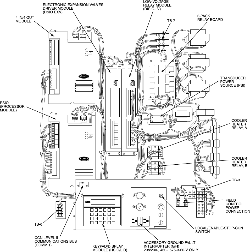
The control system consists of a processor module (PSIO),
a low-voltage relay module (DSIO-LV), 2 EXVs, an EXV
driver module (DSIO-EXV), a 6-pack relay board, a keypad
and display module (also called HSIO or LID), thermistors,
and transducers to provide inputs to the microprocessor. A
standard options module (SIO) is used to provide additional
functions. See Fig. 1 for a typical 30GN Control Panel.
MAJOR SYSTEM COMPONENTS
Processor Module — This module contains the oper-
ating software and controls the operation of the machine. It
continuously monitors information received from the vari-
ous transducers and thermistors and communicates with the
relay modules and 6-pack relay board to increase or de-
crease the active stages of capacity. The processor module
2
789
456
123
–0•
STAT EXPN
HIST CLR SCHD
SRVC SET
TEST ENTR
FUSE 1 LOCAL/
ENABLE
SW1
STOP
CCN
FUSE 3
FUSE 2
F
U
S
E
F
U
S
E
F
U
S
E
CB5
CB6
EQUIP GND
99NA505322 D
COMM 1
COMM 3 PWR
XX
S1
S2
XX
POINT NUMBER
OF
FIRST CHANNEL
COMM 3 PWR
LVEXV
STA TUS
COMM
STA TUS
COMM
12
3+
4-
HK35AA002
Potter & Brumfield
CZ770
5VDC
GFI - CO
( 5 AMP MAX )
30GT510568 –
J5
J4 J4
LEGEND
CCN — Carrier Comfort Network
TB — Terminal Block
Fig. 1 — 30GN Control Panel (040-110 Unit Shown)
3
also controls the EXV driver module (as appropriate), com-
manding it to open or close each EXV in order to maintain
the proper superheat entering the cylinders of each lead com-
pressor. Information is transmitted between the processor mod-
ule and relay module, the EXV driver module, and the key-
pad and display module through a 3-wire communications
bus. The options module is also connected to the commu-
nications bus.
For the Flotronic™ II chillers, the processor monitors sys-
tem pressure by means of 6 transducers, 3 in each lead com-
pressor. Compressor suction pressure, discharge pressure, and
oil pressure are sensed. If the processor senses high dis-
charge pressure or low suction pressure, it immediately shuts
down all compressors in the affected circuit. During opera-
tion, if low oil pressure is sensed for longer than one minute,
all compressors in the affected circuit are shut down.At start-
up, the oil pressure signal is ignored for 2 minutes. If shut-
down occurs due to any of these pressure faults, the circuit
is locked out and the appropriate fault code is displayed.
Low-Voltage Relay Module — This module closes
contacts to energize compressor unloaders and/or compres-
sors. It also senses the status of the safeties for all compres-
sors and transmits this information to the processor.
Electronic Expansion Valve Module (If So
Equipped) — This module receives signals from the pro-
cessor and operates the electronic expansion valves.
Options Module — This module allows the use of Flo-
tronic II features such as dual set point, remote reset, de-
mand limit, hot gas bypass, and accessory unloaders. The
options module also allows for reset and demand limit to be
activated from a remote 4-20 mA signal. The options mod-
ule is installed at the factory.
Keypad and Display Module (Also Called HSIO
or LID) — This device consists of a keypad with 6 func-
tion keys, 5 operative keys, 12 numeric keys, and an alpha-
numeric 8-character LCD (liquid crystal display). Key us-
age is explained in Accessing Functions and Subfunctions
section on page 24.
Control Switch — Control of the chiller is defined by
the position of the LOCAL/ENABLE-STOP-CCN switch.
This is a 3-position manual switch that allows the chiller to
be put under the control of its own Flotronic II controls, manu-
ally stopped, or put under the control of a Carrier Comfort
Network (CCN). Switch allows unit operation as shown in
Table 2.
In the LOCAL/ENABLE position, the chiller is under lo-
cal control and responds to the scheduling configuration and
set point data input at its own local interface device (keypad
and display module).
Table 2 — LOCAL/ENABLE-STOP-CCN
Switch Positions and Operation
SWITCH
POSITION UNIT
OPERATION
CONFIGURATION AND
SET POINT CONTROL
Keypad Control CCN Control
STOP Unit Cannot Run Read/Write Read Only
LOCAL/ENABLE Unit Can Run Read/Limited Write Read Only
CCN Stop — Unit Cannot Run Read Only Read/Write
Run — Unit Can Run Read Only Read/Limited
Write
In the CCN position, the chiller is under remote control
and responds only to CCN network commands. The occupied/
unoccupied conditions are defined by the network. All key-
pad and display functions can be read at the chiller regard-
less of position of the switch.
CCN run or stop condition is established by a command
from the CCN network. It is not possible to force outputs
from the CCN network, except that an emergency stop com-
mand shuts down the chiller immediately and causes ‘‘ALARM
52’’ to be displayed.
Electronic Expansion Valve (EXV) — The micro-
processor controls the EXV (if so equipped) through the EXV
driver module. Inside the expansion valve is a linear actua-
tor stepper motor.
The lead compressor in each circuit has a thermistor and
a pressure transducer located in the suction manifold after
the compressor motor. The thermistor measures the tem-
perature of the superheated gas entering the compressor cyl-
inders. The pressure transducer measures the refrigerant pressure
in the suction manifold. The microprocessor converts the pres-
sure reading to a saturated temperature. The difference be-
tween the temperature of the superheated gas and the satu-
ration temperature is the superheat. The microprocessor controls
the position of the electronic expansion valve stepper motor
to maintain 30 F (17 C) superheat.
At initial unit start-up, the EXV position is at zero. After
that, the microprocessor keeps accurate track of the valve
position in order to use this information as input for the other
control functions. The control monitors the superheat and
the rate of change of superheat to control the position of the
valve. The valve stroke is very large, which results in very
accurate control of the superheat.
Thermostatic Expansion Valves (TXV) — Model
30GN040 and 045 units with factory-installed brine option
are equipped with conventional thermostatic expansion valves
with liquid line solenoids. The liquid line solenoid valves
are not intended to be a mechanical shut-off. When service
is required, use the liquid line service valve to pump down
the system.
4
The TXV is set at the factory to maintain approximately
8 to 12° F (4.4 to 6.7° C) suction superheat leaving the cooler
by monitoring the proper amount of refrigerant into the cooler.
All TXVs are adjustable, but should not be adjusted unless
absolutely necessary. When TXV is used, thermistors T7 and
T8 are not required.
The TXV is designed to limit the cooler saturated suction
temperature to 55 F (12.8 C). This makes it possible for unit
to start at high cooler fluid temperatures without overload-
ing the compressor.
Sensors — The Flotronic™ II chiller control system gath-
ers information from sensors to control the operation of the
chiller. The units use 6 standard pressure transducers and
4 standard thermistors to monitor system pressures and tem-
peratures at various points within the chiller. Sensors are listed
in Table 3.
Table 3 — Thermistor and Transducer Locations
THERMISTORS
Sensor Location
T1 Cooler Leaving Fluid Temp
T2 Cooler Entering Fluid Temp
T7 Compressor Suction Gas Temp Circuit A
T8 Compressor Suction Gas Temp Circuit B
T10 Remote Temperature Sensor (Accessory)
PRESSURE TRANSDUCERS
Sensor Location
DPT-A Compressor A1 Discharge Pressure
SPT-A Compressor A1 Suction Pressure
OPT-A Compressor A1 Oil Pressure
DPT-B Compressor B1 Discharge Pressure
SPT-B Compressor B1 Suction Pressure
OPT-B Compressor B1 Oil Pressure
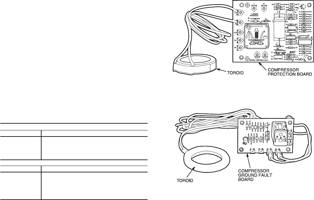
Compressor Protection Control Module (CPCS)
—Each compressor on models 30GN070 (50 Hz), 080-
110, and 230B-315B, has its own CPCS as standard equip-
ment. See Fig. 2. All 30GN040-060 and 070 (60 Hz) units
feature the CPCS as an accessory, and CR (control relay) as
standard equipment. The 30GN130-210 and associated modu-
lar units have a CR as standard equipment. The CPCS or CR
is used to control and protect the compressors and crankcase
heaters. The CPCS provides the following functions:
• compressor contactor control
• crankcase heater control
• compressor ground current protection
• status communication to processor board
• high-pressure protection
The CR provides all of the same functions as the CPCS
with the exception of compressor ground current protection.
Ground current protection is accomplished by using a CGF
(compressor ground fault module) in conjunction with the
CR. The CGF (See Fig. 3) provides the same ground fault
function as the CPCS for units where the CPCS is not
utilized.
One large relay is located on the CPCS board. This relay
(or CR) controls the crankcase heater and compressor
contactor. The CPCS also provides a set of signal contacts
that the microprocessor monitors to determine the operating
status of the compressor. If the processor board determines
that the compressor is not operating properly through the sig-
nal contacts, it will lock the compressor off by deenergizing
the proper 24-v control relay on the relay board. The
CPCS board contains logic that can detect if the current-to-
ground of any compressor winding exceeds 2.5 amps. If this
condition occurs, the CPCS module shuts down the
compressor.
A high-pressure switch with a trip pressure of 426
± 7 psig (2936 ± 48 kPa), is wired in series with the CPCS.
If this switch opens during operation, the compressor stops
and the failure is detected by the processor when the signal
contacts open. The compressor is locked off. If the lead com-
pressor in either circuit is shut down by the high-pressure
switch or ground current protector, all compressors in the
circuit are locked off.
OPERATION DATA
Capacity Control — The control system cycles
compressor to give capacity control steps as shown in
Tables 4A-4C. The unit controls leaving chilled fluid tem-
perature. Entering fluid temperature is used by the micro-
processor in determining the optimum time to add or sub-
tract steps of capacity, but is not a control set point.
The chilled fluid temperature set point can be automati-
cally reset by the return temperature reset or space and
outdoor-air temperature reset features. It can also be reset
from an external 4 to 20 mA signal, or from a network
signal.
The operating sequences shown are some of many pos-
sible loading sequences for the control of the leaving fluid
temperature. If a circuit has more unloaders than another,
that circuit will always be the lead circuit.
Fig. 2 — Compressor Protection Control Module
Fig. 3 — Compressor Ground Fault Module
5

Table 4A — Capacity Control Steps, 040-070
UNIT
30GN CONTROL
STEPS
LOADING SEQUENCE A LOADING SEQUENCE B
%Compressors %CompressorsDisplacement Displacement
(Approx) (Approx)
040 (60 Hz)
A1†,B1
1 25 A1* — —
250A1 — —
3 75 A1*, B1 — —
4 100 A1,B1 — —
040 (60 Hz)
A1†,B1**
1 25 A1* 25 B1*
250A1 50B1
3 75 A1*,B1 75 A1,B1*
4 100 A1,B1 100 A1,B1
040 (50 Hz)
045 (60 Hz)
A1†,B1
1 24 A1* — —
247A1 — —
3 76 A1*,B1 — —
4 100 A1,B1 — —
040 (50 Hz)
045 (60 Hz)
A1†,B1**
1 24 A1* 37 B1*
247A1 53B1
3 61 A1*,B1* 61 A1*,B1*
4 76 A1*,B1 84 A1,B1*
5 100 A1,B1 100 A1,B1
040 (50 Hz)
045 (60 Hz)
A1†,B1**
1 — — 21 B1††
2 — — 37 B1*
3— — 53B1
4 — — 68 A1,B1††
5 — — 84 A1,B1*
6 — — 100 A1,B1
045 (50 Hz)
050 (60 Hz)
A1†,B1
1 31 A1* — —
244A1 — —
3 87 A1*,B1 — —
4 100 A1,B1 — —
045 (50 Hz)
050 (60 Hz)
A1†,B1**
1 31 A1* 38 B1*
244A1 56B1
3 69 A1*,B1* 69 A1*,B1*
4 87 A1*,B1 82 A1,B1*
5 100 A1,B1 100 A1,B1
045 (50 Hz)
050 (60 Hz)
A1†**,B1
1 18 A1†† — —
2 31 A1* — —
3 73 A1††,B1 — —
4 87 A1*,B1 — —
5 100 A1,B1 — —
045 (50 Hz)
050 (60 Hz)
A1†**,B1**
1 18 A1†† — —
2 31 A1* — —
344A1 — —
4 56 A1††,B1* — —
5 73 A1††,B1 — —
6 87 A1*,B1 — —
7 100 A1,B1 — —
045 (50 Hz)
050 (60 Hz)
A1†,B1**
1 — — 20 B1††
2 — — 38 B1*
3— — 56B1
4 — — 51 A1*,B1††
5 — — 64 A1,B1††
6 — — 82 A1,B1*
7 — — 100 A1,B1
*Unloaded compressor.
†Compressor unloader, standard.
**Compressor unloader(s), accessory.
††Two unloaders, both unloaded.
6

Table 4A — Capacity Control Steps, 040-070 (cont)
UNIT
30GN CONTROL
STEPS
LOADING SEQUENCE A LOADING SEQUENCE B
%Compressors %CompressorsDisplacement Displacement
(Approx) (Approx)
045 (50 Hz)
050 (60 Hz)
A1†**,B1**
1 18 A1†† 20 B1††
2 31 A1* 38 B1*
344A1 56B1
4 56 A1††,B1* 64 A1,B1††
5 73 A1††,B1 82 A1,B1*
6 87 A1*,B1 100 A1,B1
7 100 A1,B1 — —
050 (50 Hz)
060 (60 Hz)
A1†,B1
1 28 A1* — —
242A1 — —
3 87 A1*,B1 — —
4 100 A1,B1 — —
050 (50 Hz)
060 (60 Hz)
A1†,B1**
1 28 A1* 38 B1*
242A1 58B1
3 67 A1*,B1* 67 A1*,B1*
4 87 A1*,B1 80 A1,B1*
5 100 A1,B1 100 A1,B1
050 (50 Hz)
060 (60 Hz)
A1†**,B1
1 15 A1†† — —
2 28 A1* — —
3 73 A1††,B1 — —
4 87 A1*,B1 — —
5 100 A1,B1 — —
050 (50 Hz)
060 (60 Hz)
A1†**,B1**
1 15 A1†† — —
2 28 A1* — —
342A1 — —
4 53 A1,B1* — —
5 73 A1††,B1 — —
6 87 A1*,B1 — —
7 100 A1,B1 — —
050 (50 Hz)
060 (60 Hz)
A1†,B1**
1 — — 18 B1††
2 — — 38 B1*
3— — 58B1
4 — — 60 A1,B1††
5 — — 80 A1,B1*
6 — — 100 A1,B1
050 (50 Hz)
060 (60 Hz)
A1†**,B1**
1 15 A1†† 18 B1††
2 28 A1* 38 B1*
342A1 58B1
4 53 A1††,B1* 60 A1,B1††
5 73 A1††,B1 80 A1,B1*
6 87 A1*,B1 100 A1,B1
7 100 A1,B1 — —
060 (50 Hz)
070 (60 Hz)
A1†,B1
1 33 A1* — —
250A1 — —
3 83 A1*,B1 — —
4 100 A1,B1 — —
060 (50 Hz)
070 (60 Hz)
A1†,B1**
1 33 A1* 33 B1*
250A1 50B1
3 67 A1*,B1* 66 A1*,B1*
4 83 A1*,B1 83 A1,B1*
5 100 A1,B1 100 A1,B1
060 (50 Hz)
070 (60 Hz)
A1†**,B1
1 16 A1†† — —
2 33 A1* — —
3 66 A1††,B1 — —
4 83 A1* — —
5 100 A1,B1 — —
060 (50 Hz)
070 (60 Hz)
A1†**,B1**
1 16 A1†† — —
2 33 A1* — —
350A1 — —
4 66 A1††,B1 — —
5 83 A1*,B1 — —
6 100 A1,B1 — —
060 (50 Hz)
070 (60 Hz)
A1†,B1**
1 — — 16 B1††
2 — — 33 B1*
3— — 50B1
4 — — 66 A1,B1††
5 — — 83 A1,B1*
6 — — 100 A1,B1
*Unloaded compressor.
†Compressor unloader, standard.
**Compressor unloader(s), accessory.
††Two unloaders, both unloaded.
7

Table 4A — Capacity Control Steps, 040-070 (cont)
UNIT
30GN CONTROL
STEPS
LOADING SEQUENCE A LOADING SEQUENCE B
%Compressors %CompressorsDisplacement Displacement
(Approx) (Approx)
060 (50 Hz)
070 (60 Hz)
A1†**,B1|
1 16 A1†† 16 B1††
2 33 A1* 33 B1*
350A1 50B1
4 66 A1††,B1 66 A1,B1††
5 83 A1*,B1 83 A1,B1*
6 100 A1,B1 100 A1,B1
070 (50 Hz)
A1†,B1
1 19 A1* — —
227A1 — —
3 65 A1*,B1 — —
4 73 A1,B1 — —
5 92 A1*,A2,B1 — —
6 100 A1,A2,B1 — —
070 (50 Hz)
A1†,B1**
1 19 A1* 31 B1*
227A1 47B1
3 49 A1*,B1* 49 A1*,B1*
4 65 A1*,B1 57 A1,B1*
5 73 A1,B1 73 A1,B1
6 76 A1*,A2,B1* 76 A1*,A2,B1*
7 92 A1*,A2,B1 84 A1,A2,B1*
8 100 A1,A2,B1 100 A1,A2,B1
070 (50 Hz)
A1†**,B1
1 11 A1†† — —
2 19 A1* — —
3 57 A1††,B1 — —
4 65 A1*,B1 — —
5 73 A1,B1 — —
6 84 A1††,A2,B1 — —
7 92 A1*,A2,B1 — —
8 100 A1,A2,B1 — —
070 (50 Hz)
A1†**,B1**
1 11 A1†† — —
2 19 A1* — —
327A1 — —
4 41 A1††,B1* — —
5 57 A1††,B1 — —
6 65 A1*,B1 — —
7 73 A1,B1 — —
8 84 A1††,A2,B1 — —
9 92 A1*,A2,B1 — —
10 100 A1,A2,B1 — —
070 (50 Hz)
A1†,B1|
1 — — 15 B1††
2 — — 31 B1*
3— — 47 B1
4 — — 57 A1*,B1*
5 — — 73 A1,B1
6 — — 84 A1,A2,B1*
7 — — 100 A1,A2,B1
070 (50 Hz)
A1†**,B1|
1 11 A1†† 15 B1††
2 19 A1* 31 B1*
327A1 47B1
4 41 A1††,B1* 54 A1*,B1*
5 57 A1††,B1 73 A1,B1
6 65 A1*,B1 84 A1,A2,B1*
7 73 A1,B1 100 A1,A2,B1
8 84 A1††,A2,B1 — —
9 92 A1*,A2,B1 — —
10 100 A1,A2,B1 — —
*Unloaded compressor.
†Compressor unloader, standard.
**One compressor unloader, accessory.
††Two unloaders, both unloaded.
\Two compressor unloaders, accessory.
8

Table 4B — Capacity Control Steps, 080-110 and Associated Modular Units
UNIT
30GN CONTROL
STEPS
LOADING SEQUENCE A LOADING SEQUENCE B
%Compressors %CompressorsDisplacement Displacement
(Approx) (Approx)
080, 230B (60 Hz)
A1†,B1†
1 22 A1* 30 B1*
234A1 44B1
3 52 A1*,B1* 52 A1*,B1*
4 67 A1*,B1 63 A1,B1*
5 78 A1,B1 78 A1,B1
6 89 A1*,A2,B1 85 A1,A2,B1*
7 100 A1,A2,B1 100 A1,A2,B1
080, 230B (60 Hz)
A1†**, B1†
1 11 A1†† — —
2 22 A1* — —
334A1 — —
4 41 A1††,B1* — —
5 55 A1††,B1 — —
6 67 A1*,B1 — —
7 78 A1,B1 — —
8 89 A1*,A2,B1 — —
9 100 A1,A2,B1 — —
080, 230B (60 Hz)
A1†,B1†**
1 — — 15 B1††
2 — — 30 B1*
3— — 44 B1
4 — — 48 A1,B1††
5 — — 63 A1,B1*
6 — — 78 A1,B1
7 — — 85 A1,A2,B1*
8 — — 100 A1,A2,B1
080, 230B (60 Hz)
A1†**,B1†**
1 11 A1†† 15 B1††
2 22 A1* 30 B1*
334A1 44B1
4 41 A1††,B1* 48 A1,B1††
5 55 A1††,B1 63 A1,B1*
6 67 A1*,B1 78 A1,B1
7 78 A1,B1 85 A1,A2,B1*
8 89 A1*,A2,B1 100 A1,A2,B1
9 100 A1,A2,B1 — —
080, 230B (50 Hz)
A1†,B1†
1 17 A1* 25 B1*
225A1 38B1
3 42 A1*,B1* 42 A1*,B1*
4 54 A1*,B1 50 A1, B1*
5 62 A1,B1 62 A1,B1
6 79 A1*,A2,B1* 79 A1*,A2,B1*
7 92 A1*,A2,B1 88 A1,A2,B1*
8 100 A1,A2,B1 100 A1,A2,B1
080, 230B (50 Hz)
A1†**,B1†
1 8 A1†† — —
2 17 A1* — —
325A1 — —
4 33 A1††,B1* — —
5 46 A1††,B1 — —
6 54 A1*,B1 — —
7 62 A1,B1 — —
8 71 A1††,A2,B1* — —
9 84 A1††,A2,B1 — —
10 92 A1*,A2,B1 — —
11 100 A1,A2,B1 — —
080, 230B (50 Hz)
A1†,B1†**
1 — — 13 B1††
2 — — 25 B1*
3— — 38 B1
4 — — 50 A1,B1*
5 — — 62 A1,B1
6 — — 67 A1*,A2,B1††
7 — — 75 A1,A2,B1††
8 — — 88 A1,A2,B1*
9 — — 100 A1,A2,B1
080, 230B (50 Hz)
A1†**,B1†**
1 8 A1†† 13 B1††
2 17 A1* 25 B1*
325A1 38B1
4 33 A1††,B1* 50 A1,B1*
5 46 A1††,B1 62 A1,B1
6 54 A1*,B1 67 A1*,A2,B1††
7 62 A1,B1 75 A1,A2,B1††
8 71 A1††,A2,B1* 88 A1,A2,B1*
9 84 A1††,A2,B1 100 A1,A2,B1
10 92 A1*,A2,B1 — —
11 100 A1,A2,B1 — —
*Unloaded compressor.
†Compressor unloader, standard.
**Compressor unloader, accessory.
††Two unloaders, both unloaded.
NOTE: These capacity control steps may vary due to lag compressor
sequencing.
9

Table 4B — Capacity Control Steps, 080-110 and Associated Modular Units (cont)
UNIT
30GN CONTROL
STEPS
LOADING SEQUENCE A LOADING SEQUENCE B
%Compressors %CompressorsDisplacement Displacement
(Approx) (Approx)
090, 245B (60 Hz)
A1†,B1†
1 18 A1* 18 B1*
227 A1 27 B1
3 35 A1*,B1* 35 A1*,B1*
4 44 A1*,B1 44 A1,B1*
5 53 A1,B1 53 A1,B1
6 56 A1*,A2,B1* 62 A1*,B1*,B2
7 65 A1*,A2,B1 71 A1,B1*,B2
8 74 A1,A2,B1 80 A1,B1,B2
9 82 A1*,A2,B1*,B2 82 A1*,A2,B1*,B2
10 91 A1*,A2,B1,B2 91 A1,A2,B1*,B2
11 100 A1,A2,B1,B2 100 A1,A2,B1,B2
090, 245B (60 Hz)
A1†**,B1†
1 9 A1†† — —
2 18 A1* — —
327 A1 — —
4 35 A1††,B1 — —
5 44 A1*,B1 — —
6 53 A1,B1 — —
7 56 A1††,A2,B1 — —
8 65 A1*,A2,B1 — —
9 74 A1,A2,B1 — —
10 82 A1††,A2,B1,B2 — —
11 91 A1*,A2,B1,B2 — —
12 100 A1,A2,B1,B2 — —
090, 245B (60 Hz)
A1†,B1†**
1 — — 9 B1††
2 — — 18 B1*
3— — 27 B1
4 — — 35 A1,B1††
5 — — 44 A1,B1*
6 — — 53 A1,B1
7 — — 62 A1,B1††,B2
8 — — 71 A1,B1*,B2
9 — — 80 A1,B1,B2
10 — — 82 A1,A2,B1††,B2
11 — — 91 A1,A2,B1*,B2
12 — — 100 A1,A2,B1,B2
090, 245B (60 Hz)
A1†**,B1†**
1 9 A1†† 9 B1††
2 18 A1* 18 B1*
327 A1 27 B1
4 35 A1††,B1 35 A1,B1††
5 44 A1*,B1 44 A1,B1*
6 53 A1,B1 53 A1,B1
7 56 A1††,A2,B1 62 A1,B1††,B2
8 65 A1*,A2,B1 71 A1,B1*,B2
9 74 A1,A2,B1 80 A1,B1,B2
10 82 A1††,A2,B1,B2 82 A1,A2,B1††,B2
11 91 A1*,A2,B1,B2 91 A1,A2,B1*,B2
12 100 A1,A2,B1,B2 100 A1,A2,B1,B2
090, 245B (50 Hz)
A1†,B1†
1 14 A1* 14 B1*
221 A1 21 B1
3 29 A1*,B1* 29 A1*,B1*
4 36 A1*,B1 36 A1,B1*
5 43 A1,B1 43 A1,B1
6 61 A1*,A2,B1* 53 A1*,B1*,B2
7 68 A1*,A2,B1 60 A1,B1*,B2
8 75 A1,A2,B1 67 A1,B1,B2
9 86 A1*,A2,B1*,B2 86 A1*,A2,B1*,B2
10 93 A1*,A2,B1,B2 93 A1,A2,B1*,B2
11 100 A1,A2,B1,B2 100 A1,A2,B1,B2
090, 245B (50 Hz)
A1†**,B1†
1 7 A1†† — —
2 14 A1* — —
321 A1 — —
4 29 A1††,B1 — —
5 36 A1*,B1 — —
6 43 A1,B1 — —
7 54 A1††,A2,B1* — —
8 61 A1††,A2,B1 — —
9 68 A1*,A2,B1 — —
10 75 A1,A2,B1 — —
11 79 A1††,A2,B1*,B2 — —
12 86 A1††,A2,B1,B2 — —
13 93 A1*,A2,B1,B2 — —
14 100 A1,A2,B1,B2 — —
*Unloaded compressor.
†Compressor unloader, standard.
**Compressor unloader, accessory.
††Two unloaders, both unloaded.
NOTE: These capacity control steps may vary due to lag compressor
sequencing.
10

Table 4B — Capacity Control Steps, 080-110 and Associated Modular Units (cont)
UNIT
30GN CONTROL
STEPS
LOADING SEQUENCE A LOADING SEQUENCE B
%Compressors %CompressorsDisplacement Displacement
(Approx) (Approx)
090, 245B (50 Hz)
A1†,B1†**
1 — — 7 B1††
2 — — 14 B1*
3— — 21 B1
4 — — 29 A1,B1††
5 — — 36 A1,B1*
6 — — 43 A1,B1
7 — — 46 A1*,B1††,B2
8 — — 53 A1,B1††,B2
9 — — 60 A1,B1*,B2
10 — — 67 A1,B1,B2
11 — — 79 A1*,A2,B1††,B1
12 — — 86 A1,A2,B1††,B1
13 — — 93 A1,A2,B1*,B2
14 — — 100 A1,2,B1,B2
090, 245B (50 Hz)
A1†**,B1†**
1 7 A1†† 7 B1††
2 14 A1* 14 B1*
321 A1 21 B1
4 29 A1††,B1 29 A1,B1††
5 36 A1*,B1 36 A1,B1*
6 43 A1,B1 43 A1,B1
7 49 A1††,A2,B1†† 46 A1*,B1††,B2
8 54 A1††,A2,B1* 53 A1,B1††,B2
9 61 A1††,A2,B1 60 A1,B1*,B2
10 68 A1*,A2,B1 67 A1,B1,B2
11 75 A1,A2,B1 72 A1††,A2,B1††,B2
12 79 A1††,A2,B1*,B2 79 A1*,A2,B1††,B2
13 86 A1††,A2,B1,B2 86 A1,A2,B1††,B2
14 93 A1*,A2,B1,B2 93 A1,A2,B1*,B2
15 100 A1,A2,B1,B2 100 A1,A2,B1,B2
100, 255B,
270B (60 Hz)
A1†,B1†
1 16 A1* 16 A1*
223 A1 23 A1
3 31 A1*,B1* 31 A1*,B1*
4 39 A1*,B1 39 A1*,B1
5 46 A1,B1 46 A1,B1
6 58 A1*,A2,B1* 58 A1*,A2,B1*
7 66 A1*,A2,B1 66 A1*,A2,B1
8 73 A1,A2,B1 73 A1,A2,B1
9 85 A1*,A2,B1*,B2 85 A1*,A2,B1*,B2
10 92 A1*,A2,B1,B2 92 A1*,A2,B1,B2
11 100 A1,A2,B1,B2 100 A1,A2,B1,B2
100, 255B,
270B (60 Hz)
A1†**,B1†
1 8 A1†† — —
2 16 A1* — —
323 A1 — —
4 31 A1††,B1 — —
5 39 A1*,B1 — —
6 46 A1,B1 — —
7 50 A1††,A2,B1* — —
8 58 A1††,A2,B1 — —
9 66 A1*,A2,B1 — —
10 73 A1,A2,B1 — —
11 77 A1††,A2,B1*,B2 — —
12 85 A1††,A2,B1,B2 — —
13 92 A1*,A2,B1,B2 — —
14 100 A1,A2,B1,B2 — —
100, 255B,
270B (60 Hz)
A1†,B1†**
1 — — 8 B1††
2 — — 16 B1*
3— — 23 B1
4 — — 31 A1,B1††
5 — — 39 A1,B1*
6 — — 46 A1,B1
7 — — 50 A1*,B1††,B2
8 — — 58 A1,B1††,B2
9 — — 66 A1,B1*,B2
10 — — 73 A1,B1,B2
11 — — 77 A1*,A2,B1††,B2
12 — — 85 A1,A2,B1††,B2
13 — — 92 A1,A2,B1*,B2
14 — — 100 A1,A2,B1,B2
*Unloaded compressor.
†Compressor unloader, standard.
**Compressor unloader, accessory.
††Two unloaders, both unloaded.
NOTE: These capacity control steps may vary due to lag compressor
sequencing.
11

Table 4B — Capacity Control Steps, 080-110 and Associated Modular Units (cont)
UNIT
30GN CONTROL
STEPS
LOADING SEQUENCE A LOADING SEQUENCE B
%Compressors %CompressorsDisplacement Displacement
(Approx) (Approx)
100, 255B,
270B (60 Hz)
A1†**,B1†**
1 8 A1†† 8 B1††
2 16 A1* 16 B1*
323A1 23B1
4 31 A1††,B1 31 A1,B1††
5 39 A1*,B1 39 A1,B1*
6 46 A1,B1 46 A1,B1
7 50 A1††,A2,B1* 50 A1*,B1††,B2
8 58 A1††,A2,B1 58 A1,B1††,B2
9 66 A1*,A2,B1 66 A1,B1*,B2
10 73 A1,A2,B1 73 A1,B1,B2
11 77 A1††,A2,B1*,B2 77 A1*,A2,B1††,B2
12 85 A1††,A2,B1,B2 85 A1,A2,B1††,B2
13 92 A1*,A2,B1,B2 92 A1,A2,B1*,B2
14 100 A1,A2,B1,B2 100 A1,A2,B1,B2
100, 255B,
270B (50 Hz)
A1†,B1†
1 13 A1* 13 B1*
220A1 20B1
3 26 A1*,B1* 26 A1*,B1*
4 33 A1,B1 33 A1,B1*
5 40 A1,B1 40 A1,B1
6 57 A1*,A2,B1* 57 A1*,B1*,B2
7 63 A1*,A2,B1 63 A1,B1*,B2
8 70 A1,A2,B1 70 A1,B1,B2
9 87 A1*,A2,B1*,B2 87 A1*,A2,B1*,B2
10 93 A1*,A2,B1,B2 93 A1,A2,B1*,B2
11 100 A1,A2,B1,B2 100 A1,A2,B1,B2
100, 255B,
270B (50 Hz)
A1†**,B1†
1 7 A1†† — —
2 13 A1* — —
320 A1 — —
4 26 A1††,B1 — —
5 33 A1*,B1 — —
6 40 A1,B1 — —
7 50 A1††,A2,B1* — —
8 57 A1††,A2,B1 — —
9 63 A1*,A2,B1 — —
10 70 A1,A2,B1 — —
11 80 A1††,A2,B1*,B2 — —
12 87 A1††,A2,B1,B2 — —
13 93 A1*,A2,B1,B2 — —
14 100 A1,A2,B1,B2 — —
100, 255B,
270B (50 Hz)
A1†,B1†**
1 — — 7 B1††
2 — — 13 B1*
3— — 20 B1
4 — — 26 A1,B1††
5 — — 33 A1,B1*
6 — — 40 A1,B1
7 — — 50 A1*,B1††,B2
8 — — 57 A1,B1††,B2
9 — — 63 A1,B1*,B2
10 — — 70 A1,B1,B2
11 — — 80 A1*,A2,B1††,B2
12 — — 87 A1,A2,B1††,B2
13 — — 93 A1,A2,B1*,B2
14 — — 100 A1,A2,B1,B2
100, 255B,
270B (50 Hz)
A1†**,B1†**
1 7 A1†† 7 B1††
2 13 A1* 13 B1*
320A1 20B1
4 26 A1††,B1 26 A1,B1††
5 33 A1*,B1 33 A1,B1*
6 40 A1,B1 40 A1,B1
7 43 A1††,A2,B1†† 43 A1††,B1††,B2
8 50 A1††,A2,B1* 50 A1*,B1††,B2
9 57 A1††,A2,B1 57 A1,B1††,B2
10 63 A1*,A2,B1 63 A1,B1*,B2
11 70 A1,A2,B1 70 A1,B1,B2
12 74 A1††,A2,B1††,B2 74 A1††,A2,B1††,B2
13 80 A1††,A2,B1*,B2 80 A1*,A2,B1††,B2
14 89 A1††,A2,B1,B2 87 A1,A2,B1††,B2
15 93 A1*,A2,B1,B2 93 A1,A2,B1*,B2
16 100 A1,A2,B1,B2 100 A1,A2,B1,B2
*Unloaded compressor.
†Compressor unloader, standard.
**Compressor unloader, accessory.
††Two unloaders, both unloaded.
NOTE: These capacity control steps may vary due to lag compressor
sequencing.
12

Table 4B — Capacity Control Steps, 080-110 and Associated Modular Units (cont)
UNIT
30GN CONTROL
STEPS
LOADING SEQUENCE A LOADING SEQUENCE B
%Compressors %CompressorsDisplacement Displacement
(Approx) (Approx)
110, 290B,
315B (60 Hz)
A1†,B1†
1 14 A1* 14 B1*
221 A1 21 B1
3 29 A1*,B1* 29 A1*,B1*
4 36 A1*,B1 36 A1,B1*
5 43 A1,B1 43 A1,B1
6 61 A1*,A2,B1* 53 A1*,B1*,B2
7 68 A1*,A2,B1 60 A1,B1*,B2
8 75 A1,A2,B1 67 A1,B1,B2
9 86 A1*,A2,B1*,B2 86 A1*,A2,B1*,B2
10 93 A1*,A2,B1,B2 93 A1,A2,B1*,B2
11 100 A1,A2,B1,B2 100 A1,A2,B1,B2
110, 290B,
315B (60 Hz)
A1†**,B1†
1 7 A1†† — —
2 14 A1* — —
321 A1 — —
4 29 A1††,B1 — —
5 36 A1*,B1 — —
6 43 A1,B1 — —
7 54 A1††,A2,B1* — —
8 61 A1††,A2,B1 — —
9 68 A1*,A2,B1 — —
10 75 A1,A2,B1 — —
11 79 A1††,A2,B1*,B2 — —
12 86 A1††,A2,B1,B2 — —
13 93 A1*,A2,B1,B2 — —
14 100 A1,A2,B1,B2 — —
110, 290B,
315B (60 Hz)
A1†,B1†**
1 — — 7 B1††
2 — — 14 B1*
3— — 21 B1
4 — — 29 A1,B1††
5 — — 36 A1,B1*
6 — — 43 A1,B1
7 — — 46 A1*,B1††,B2
8 — — 53 A1,B1††,B2
9 — — 60 A1,B1*,B2
10 — — 67 A1,B1,B2
11 — — 79 A1*,A2,B1††,B2
12 — — 86 A1,A2,B1††,B2
13 — — 93 A1,A2,B1*,B2
14 — — 100 A1,A2,B1,B2
110, 290B,
315B (60 Hz)
A1†**,B1†**
1 7 A1†† 7 B1††
2 14 A1* 14 B1*
321 A1 21 B1
4 29 A1††,B1 29 A1,B1††
5 36 A1*,B1 36 A1,B1*
6 43 A1,B1 43 A1,B1
7 47 A1††,A2,B1†† 46 A1*,B1††,B2
8 54 A1††,A2,B1* 53 A1,B1††,B2
9 61 A1††,A2,B1 60 A1,B1*,B2
10 68 A1*,A2,B1 67 A1,B1,B2
11 75 A1,A2,B1 72 A1††,A2,B1††,B2
12 79 A1††,A2,B1*,B2 79 A1*,A2,B1††,B2
13 86 A1††,A2,B1,B2 86 A1,A2,B1††,B2
14 93 A1*,A2,B1,B2 93 A1,A2,B1*,B2
15 100 A1,A2,B1,B2 100 A1,A2,B1,B2
110, 290B,
315B (50 Hz)
A1†,B1†
1 17 A1* 17 B1*
225 A1 25 B1
3 33 A1*,B1* 33 A1*,B1*
4 42 A1*,B1 42 A1,B1*
5 50 A1,B1 50 A1,B1
6 58 A1*,A2,B1* 58 A1*,B1*,B2
7 67 A1*,A2,B1 67 A1,B1*,B2
8 75 A1,A2,B1 75 A1,B1,B2
9 83 A1*,A2,B1*,B2 83 A1*,A2,B1*,B2
10 92 A1*,A2,B1,B2 92 A1,A2,B1*,B2
11 100 A1,A2,B1,B2 100 A1,A2,B1,B2
*Unloaded compressor.
†Compressor unloader, standard.
**Compressor unloader, accessory.
††Two unloaders, both unloaded.
NOTE: These capacity control steps may vary due to lag compressor
sequencing.
13

Table 4B — Capacity Control Steps, 080-110 and Associated Modular Units (cont)
UNIT
30GN CONTROL
STEPS
LOADING SEQUENCE A LOADING SEQUENCE B
%Compressors %CompressorsDisplacement Displacement
(Approx) (Approx)
110, 290B,
315B (50 Hz)
A1†**,B1†
1 8 A1†† — —
2 17 A1* — —
325 A1 — —
4 33 A1††,B1 — —
5 42 A1*,B1 — —
6 50 A1,B1 — —
7 58 A1††,A2,B1 — —
8 67 A1*,A2,B1 — —
9 75 A1,A2,B1 — —
10 83 A1††,A2,B1,B2 — —
11 92 A1*,A2,B1,B2 — —
12 100 A1,A2,B1,B2 — —
110, 290B,
315B (50 Hz)
A1†,B1†**
1 — — 8 B1††
2 — — 17 B1*
3— — 25 B1
4 — — 33 A1,B1††
5 — — 42 A1,B1*
6 — — 50 A1,B1
7 — — 58 A1,B1††,B2
8 — — 67 A1,B1*,B2
9 — — 75 A1,B1,B2
10 — — 83 A1,A2,B1††,B2
11 — — 92 A1,A2,B1*,B2
12 — — 100 A1,A2,B1,B2
110, 290B,
315B (50 Hz)
A1†**,B1†**
1 8 A1†† 8 B1††
2 17 A1* 17 B1*
325A1 25B1
4 33 A1††,B1 33 A1,B1††
5 42 A1*,B1 42 A1,B1*
6 50 A1,B1 50 A1,B1
7 58 A1††,A2,B1 58 A1,B1††,B2
8 67 A1*,A2,B1 67 A1,B1*,B2
9 75 A1,A2,B1 75 A1,B1,B2
10 83 A1††,A2,B1,B2 83 A1,A2,B1††,B2
11 92 A1*,A2,B1,B2 92 A1,A2,B1*,B2
12 100 A1,A2,B1,B2 100 A1,A2,B1,B2
*Unloaded compressor.
†Compressor unloader, standard.
**Compressor unloader, accessory.
††Two unloaders, both unloaded.
NOTE: These capacity control steps may vary due to lag compressor
sequencing.
14

Table 4C — Capacity Control Steps, 130-210 and Associated Modular Units
UNIT
30GN CONTROL
STEPS
LOADING SEQUENCE A LOADING SEQUENCE B
%Compressors %CompressorsDisplacement Displacement
(Approx) (Approx)
130 (60 Hz)
A1†,B1†
1
2
3
4
5
6
7
8
9
10
11
14
21
28
35
42
58
64
71
87
93
100
A1*
A1
A1*,B1*
A1*,B1
A1,B1
A1*,A2,B1*
A1*,A2,B1
A1,A2,B1
A1*,A2,B1*,B2
A1*,A2,B1,B2
A1,A2,B1,B2
14
21
28
35
42
58
64
71
87
93
100
B1*
B1
A1*,B1*
A1,B1*
A1,B1
A1*,B1*,B2
A1,B1*,B2
A1,B1,B2
A1*,A2,B1*,B2
A1,A2,B1*,B2
A1,A2,B1,B2
130 (60 Hz)
A1†**,B1†
1
2
3
4
5
6
7
8
9
10
11
12
13
14
15
8
14
21
22
28
35
42
51
58
64
71
80
87
93
100
A1††
A1*
A1
A1††,B1*
A1††,B1
A1*,B1
A1,B1
A1††,A2,B1*
A1††,A2,B1
A1*,A2,B1
A1,A2,B1
A1††,A2,B1*,B2
A1††,A2,B1,B2
A1*,A2,B1,B2
A1,A2,B1,B2
—
—
—
—
—
—
—
—
—
—
—
—
—
—
—
—
—
—
—
—
—
—
—
—
—
—
—
—
—
—
130 (60 Hz)
A1†,B1†**
1
2
3
4
5
6
7
8
9
10
11
12
13
14
15
—
—
—
—
—
—
—
—
—
—
—
—
—
—
—
—
—
—
—
—
—
—
—
—
—
—
—
—
—
—
8
14
21
22
28
35
42
51
58
64
71
80
87
93
100
B1††
B1*
B1
A1*,B1††
A1,B1††
A1,B1*
A1,B1
A1*,B1††,B2
A1,B1††,B2
A1,B1*,B2
A1,B1,B2
A1*,A2,B1††,B2
A1,A2,B1††,B2
A1,A2,B1*,B2
A1,A2,B1,B2
130 (60 Hz)
A1†**,B1†**
1
2
3
4
5
6
7
8
9
10
11
12
13
14
15
16
17
8
14
21
22
28
35
42
44
51
58
64
71
73
80
87
93
100
A1††
A1*
A1
A1††,B1*
A1††,B1
A1*,B1
A1,B1
A1††,A2,B1††
A1††,A2,B1*
A1††,A2,B1
A1*,A2,B1
A1,A2,B1
A1††,A2,B1††,B2
A1††,A2,B1*,B2
A1††,A2,B1,B2
A1*,A2,B1,B2
A1,A2,B1,B2
8
14
21
22
28
35
42
44
51
58
64
71
73
80
87
93
100
B1††
B1*
B1
A1*,B1††
A1,B1††
A1,B1*
A1,B1
A1††,B1††,B2
A1*,B1††,B2
A1,B1††,B2
A1,B1*,B2
A1,B1,B2
A1††,A2,B1††,B2
A1*,A2,B1††,B2
A1,A2,B1††,B2
A1,A2,B1*,B2
A1,A2,B1,B2
130 (50 Hz)
A1†,B1†
1
2
3
4
5
6
7
8
9
10
11
12
13
14
10
14
26
35
39
44
53
57
69
78
82
87
96
100
A1*
A1
A1*,B1*
A1*,B1
A1,B1
A1*,A2,B1*
A1*,A2,B1
A1,A2,B1
A1*,A2,B1*,B2
A1*,A2,B1,B2
A1,A2,B1,B2
A1*,A2,A3,B1*,B2
A1*,A2,A3,B1,B2
A1,A2,A3,B1,B2
16
25
26
31
39
51
56
64
69
74
82
87
91
100
B1*
B1
A1*,B1*
A1,B1*
A1,B1
A1*,B1*,B2
A1,B1*,B2
A1,B1,B2
A1*,A2,B1*,B2
A1,A2,B1*,B2
A1,A2,B1,B2
A1*,A2,A3,B1*,B2
A1,A2,A3,B1*,B2
A1,A2,A3,B1,B2
*Unloaded compressor.
†Compressor unloader, standard.
**Compressor unloader, accessory.
††Two unloaders, both unloaded.
NOTE: These capacity control steps may vary due to lag compressor
sequencing.
15

Table 4C — Capacity Control Steps, 130-210 and Associated Modular Units (cont)
UNIT
30GN CONTROL
STEPS
LOADING SEQUENCE A LOADING SEQUENCE B
%Compressors %CompressorsDisplacement Displacement
(Approx) (Approx)
130 (50 Hz)
A1†**,B1†
1
2
3
4
5
6
7
8
9
10
11
12
13
14
15
16
17
18
19
6
10
14
22
31
35
39
40
49
53
57
65
74
78
82
83
91
96
100
A1††
A1*
A1
A1††,B1*
A1††,B1
A1*,B1
A1,B1
A1††,A2,B1*
A1††,A2,B1
A1*,A2,B1
A1,A2,B1
A1††,A2,B1*,B2
A1††,A2,B1,B2
A1*,A2,B1,B2
A1,A2,B1,B2
A1††,A2,A3,B1*,B2
A1††,A2,A3,B1,B2
A1*,A2,A3,B1,B2
A1,A2,A3,B1,B2
—
—
—
—
—
—
—
—
—
—
—
—
—
—
—
—
—
—
—
—
—
—
—
—
—
—
—
—
—
—
—
—
—
—
—
—
—
—
130 (50 Hz)
A1†,B1†**
1
2
3
4
5
6
7
8
9
10
11
12
13
14
15
—
—
—
—
—
—
—
—
—
—
—
—
—
—
—
—
—
—
—
—
—
—
—
—
—
—
—
—
—
—
8
16
25
31
39
43
47
56
64
65
74
82
83
91
100
B1††
B1*
B1
A1,B1*
A1,B1
A1*,B1††,B2
A1,B1††,B2
A1,B1*,B2
A1,B1,B2
A1,A2,B1††,B2
A1,A2,B1*,B2
A1,A2,B1,B2
A1,A2,A3,B1††,B2,B3
A1,A2,A3,B1*,B2,B3
A1,A2,A3,B1,B2,B3
130 (50 Hz)
A1†**,B1†**
1
2
3
4
5
6
7
8
9
10
11
12
13
14
15
16
17
18
19
6
10
14
22
31
35
39
40
49
53
57
65
74
78
82
83
91
96
100
A1††
A1*
A1
A1††,B1*
A1††,B1
A1*,B1
A1,B1
A1††,A2,B1*
A1††,A2,B1
A1*,A2,B1
A1,A2,B1
A1††,A2,B1*,B2
A1††,A2,B1,B2
A1*,A2,B1,B2
A1,A2,B1,B2
A1††,A2,A3,B1*,B2
A1††,A2,A3,B1,B2
A1*,A2,A3,B1,B2
A1,A2,A3,B1,B2
8
16
25
31
39
43
47
56
64
65
74
82
83
91
100
—
—
—
—
B1††
B1*
B1
A1,B1*
A1,B1
A1*,B1††,B2
A1,B1††,B2
A1,B1*,B2
A1,B1,B2
A1,A2,B1††,B2
A1,A2,B1*,B2
A1,A2,B1,B2
A1,A2,A3,B1††,B2
A1,A2,A3,B1*,B2
A1,A2,A3,B1,B2
—
—
—
—
150, 230A, 245A,
255A (60 Hz)
A1†,B1†
1
2
3
4
5
6
7
8
9
10
11
12
13
14
11
15
29
38
42
44
53
58
71
80
85
86
95
100
A1*
A1
A1*,B1*
A1*,B1
A1,B1
A1*,A2,B1*
A1*,A2,B1
A1,A2,B1
A1*,A2,B1*,B2
A1*,A2,B1,B2
A1,A2,B1,B2
A1*,A2,A3,B1*,B2
A1*,A2,A3,B1,B2
A1,A2,A3,B1,B2
18
27
29
33
42
55
60
69
71
75
85
86
91
100
B1*
B1
A1*,B1*
A1,B1*
A1,B1
A1*,B1*,B2
A1,B1*,B2
A1,B1,B2
A1*,A2,B1*,B2
A1,A2,B1*,B2
A1,A2,B1,B2
A1*,A2,A3,B1*,B2
A1,A2,A3,B1*,B2
A1,A2,A3,B1,B2
*Unloaded compressor.
†Compressor unloader, standard.
**Compressor unloader, accessory.
††Two unloaders, both unloaded.
NOTE: These capacity control steps may vary due to lag compressor
sequencing.
16

Table 4C — Capacity Control Steps, 130-210 and Associated Modular Units (cont)
UNIT
30GN CONTROL
STEPS
LOADING SEQUENCE A LOADING SEQUENCE B
%Compressors %CompressorsDisplacement Displacement
(Approx) (Approx)
150, 230A, 245A,
255A (60 Hz)
A1†**,B1†
1
2
3
4
5
6
7
8
9
10
11
12
13
14
15
16
17
6
11
15
24
33
38
42
49
53
58
66
75
80
85
91
95
100
A1††
A1*
A1
A1††,B1*
A1††,B1
A1*,B1
A1,B1
A1††,A2,B1
A1*,A2,B1
A1,A2,B1
A1††,A2,B1*,B2
A1††,A2,B1,B2
A1*,A2,B1,B2
A1,A2,B1,B2
A1††,A2,A3,B1,B2
A1*,A2,A3,B1,B2
A1,A2,A3,B1,B2
—
—
—
—
—
—
—
—
—
—
—
—
—
—
—
—
—
—
—
—
—
—
—
—
—
—
—
—
—
—
—
—
—
—
150, 230A, 245A,
255A (60 Hz)
A1†,B1†**
1
2
3
4
5
6
7
8
9
10
11
12
13
—
—
—
—
—
—
—
—
—
—
—
—
—
—
—
—
—
—
—
—
—
—
—
—
—
—
9
18
27
33
42
46
51
60
69
75
85
91
100
B1††
B1*
B1
A1,B1*
A1,B1
A1*,B1††,B2
A1,B1††,B2
A1,B1*,B2
A1,B1,B2
A1,A2,B1*,B2
A1,A2,B1,B2
A1,A2,A3,B1*,B2
A1,A2,A3,B1,B2
150, 230A, 245A,
255A (60 Hz)
A1†**,B1†**
1
2
3
4
5
6
7
8
9
10
11
12
13
14
15
16
17
6
11
15
24
33
38
42
49
53
58
66
75
80
85
91
95
100
A1††
A1*
A1
A1††,B1*
A1††,B1
A1*,B1
A1,B1
A1††,A2,B1
A1*,A2,B1
A1,A2,B1
A1††,A2,B1*,B2
A1††,A2,B1,B2
A1*,A2,B1,B2
A1,A2,B1,B2
A1††,A2,A3,B1,B2
A1*,A2,A3,B1,B2
A1,A2,A3,B1,B2
9
18
27
33
42
46
51
60
69
75
86
91
100
—
—
—
—
B1††
B1*
B1
A1,B1*
A1,kB1
A1*,B1††,B2
A1,B1††,B2
A1,B1*,B2
A1,B1,B2
A1,A2,B1*,B2
A1,A2,B1,B2
A1,A2,A3,B1*,B2
A1,A2,A3,B1,B2
—
—
—
—
150, 230A, 245A,
255A (50 Hz)
A1†,B1†
1
2
3
4
5
6
7
8
9
10
11
12
13
14
13
20
26
33
40
46
53
60
66
73
80
86
93
100
A1*
A1
A1*,B1*
A1*,B1
A1,B1
A1*,A2,B1*
A1*,A2,B1
A1,A2,B1
A1*,A2,B1*,B2
A1*,A2,B1,B2
A1,A2,B1,B2
A1*,A2,A3,B1*,B2
A1*,A2,A3,B1,B2
A1,A2,A3,B1,B2
13
20
26
33
40
46
53
60
66
73
80
86
93
100
B1*
B1
A1*,B1*
A1,B1*
A1,B1
A1*,B1*,B2
A1,B1*,B2
A1,B1,B2
A1*,A2,B1*,B2
A1,A2,B1*,B2
A1,A2,B1,B2
A1*,A2,A3,B1*,B2
A1,A2,A3,B1*,B2
A1,A2,A3,B1,B2
150, 230A, 245A,
255A (50 Hz)
A1†**,B1†
1
2
3
4
5
6
7
8
9
10
11
12
13
14
15
6
13
20
26
33
40
46
53
60
66
73
80
86
93
100
A1††
A1*
A1
A1††,B1
A1*,B1
A1,B1
A1††,A2,B1
A1*,A2,B1
A1,A2,B1
A1††,A2,B1,B2
A1*,A2,B1,B2
A1,A2,B1,B2
A1††,A2,A3,B1,B2
A1*,A2,A3,B1,B2
A1,A2,A3,B1,B2
—
—
—
—
—
—
—
—
—
—
—
—
—
—
—
—
—
—
—
—
—
—
—
—
—
—
—
—
—
—
*Unloaded compressor.
†Compressor unloader, standard.
**Compressor unloader, accessory.
††Two unloaders, both unloaded.
NOTE: These capacity control steps may vary due to lag compressor
sequencing.
17

Table 4C — Capacity Control Steps, 130-210 and Associated Modular Units (cont)
UNIT
SIZE CONTROL
STEPS
LOADING SEQUENCE A LOADING SEQUENCE B
%Compressors %CompressorsDisplacement Displacement
(Approx) (Approx)
150, 230A, 245A,
255A (50 Hz)
A1†,B1†**
1
2
3
4
5
6
7
8
9
10
11
12
13
14
15
—
—
—
—
—
—
—
—
—
—
—
—
—
—
—
—
—
—
—
—
—
—
—
—
—
—
—
—
—
—
6
13
20
26
33
40
46
53
60
66
73
80
86
93
100
B1††
B1*
B1
A1,B1††
A1,B1*
A1,B1
A1,B1††,B2
A1,B1*,B2
A1,B1,B2
A1,A2,B1††,B2
A1,A2,B1*,B2
A1,A2,B1,B2
A1,A2,A3,B1††,B2
A1,A2,A3,B1*,B2
A1,A2,A3,B1,B2
150, 230A, 245A,
255A (50 Hz)
A1†**,B1†**
1
2
3
4
5
6
7
8
9
10
11
12
13
14
15
6
13
20
26
33
40
46
53
60
66
73
80
86
93
100
A1††
A1*
A1
A1††,B1
A1*,B1
A1,B1
A1††,A2,B1
A1*,A2,B1
A1,A2,B1
A1††,A2,B1,B2
A1*,A2,B1,B2
A1,A2,B1,B2
A1††,A2,A3,B1,B2
A1*,A2,A3,B1,B2
A1,A2,A3,B1,B2
6
13
20
26
33
40
46
53
60
66
73
80
86
93
100
B1††
B1*
B1
A1,B1††
A1,B1*
A1,B1
A1,B1††,B2
A1,B1*,B2
A1,B1,B2
A1,A2,B1††,B2
A1,A2,B1*,B2
A1,A2,B1,B2
A1,A2,A3,B1††,B2
A1,A2,A3,B1*,B2
A1,A2,A3,B1,B2
170, 270A,
330A/B (60 Hz)
A1†,B1†
1
2
3
4
5
6
7
8
9
10
11
12
13
14
15
16
17
11
17
23
28
33
39
45
50
56
61
67
73
78
83
89
95
100
A1*
A1
A1*,B1*
A1*,B1
A1,B1
A1*,A2,B1*
A1*,A2,B1
A1,A2,B1
A1*,A2,B1*,B2
A1*,A2,B1,B2
A1,A2,B1,B2
A1*,A2,A3,B1*,B2
A1*,A2,A3,B1,B2
A1,A2,A3,B1,B2
A1*,A2,A3,B1*,B2,B3
A1*,A2,A3,B1,B2,B3
A1,A2,A3,B1,B2,B3
11
17
23
28
33
39
45
50
56
61
67
73
78
83
89
95
100
B1*
B1
A1*,B1*
A1,B1*
A1,B1
A1*,B1*,B2
A1,B1*,B2
A1,B1,B2
A1*,A2,B1*,B2
A1,A2,B1*,B2
A1,A2,B1,B2
A1*,A2,B1*,B2,B3
A1,A2,B1*,B2,B3
A1,A2,B1,B2,B3
A1*,A2,A3,B1*,B2,B3
A1,A2,A3,B1*,B2,B3
A1,A2,A3,B1,B2,B3
170, 270A,
330A/B (60 Hz)
A1†**,B1†
1
2
3
4
5
6
7
8
9
10
11
12
13
14
15
16
17
18
19
20
21
22
23
6
11
17
17
23
28
33
34
39
45
50
51
56
61
67
67
73
78
83
84
89
95
100
A1††
A1*
A1
A1††,B1*
A1††,B1
A1*,B1
A1,B1
A1††,A2,B1*
A1††,A2,B1
A1*,A2,B1
A1,A2,B1
A1††,A2,B1*,B2
A1††,A2,B1,B2
A1*,A2,B1,B2
A1,A2,B1,B2
A1††,A2,A3,B1*,B2
A1††,A2,A3,B1,B2
A1*,A2,A3,B1,B2
A1,A2,A3,B1,B2
A1††,A2,A3,B1*,B2,B3
A1††,A2,A3,B1,B2,B3
A1*,A2,A3,B1,B2,B3
A1,A2,A3,B1,B2,B3
—
—
—
—
—
—
—
—
—
—
—
—
—
—
—
—
—
—
—
—
—
—
—
—
—
—
—
—
—
—
—
—
—
—
—
—
—
—
—
—
—
—
—
—
—
—
*Unloaded compressor.
†Compressor unloader, standard.
**Compressor unloader, accessory.
††Two unloaders, both unloaded.
NOTE: These capacity control steps may vary due to lag compressor
sequencing.
18

Table 4C — Capacity Control Steps, 130-210 and Associated Modular Units (cont)
UNIT
SIZE CONTROL
STEPS
LOADING SEQUENCE A LOADING SEQUENCE B
%Compressors %CompressorsDisplacement Displacement
(Approx) (Approx)
170, 270A,
330A/B (60 Hz)
A1†,B1†**
1
2
3
4
5
6
7
8
9
10
11
12
13
14
15
16
17
18
19
20
21
22
23
—
—
—
—
—
—
—
—
—
—
—
—
—
—
—
—
—
—
—
—
—
—
—
—
—
—
—
—
—
—
—
—
—
—
—
—
—
—
—
—
—
—
—
—
—
—
6
11
17
17
23
28
33
34
39
45
50
51
56
61
67
67
73
78
83
84
89
95
100
B1††
B1*
B1
A1*,B1††
A1,B1††
A1,B1*
A1,B1
A1*,B1††,B2
A1,B1††,B2
A1,B1*,B2
A1,B1,B2
A1*,A2,B1††,B2
A1,A2,B1††,B2
A1,A2,B1*,B2
A1,A2,B1,B2
A1*,A2,B1††,B2,B3
A1,A2,B1††,B2,B3
A1,A2,B1*,B2,B3
A1,A2,B1,B2,B3
A1*,A2,A3,B1††,B2,B3
A1,A2,A3,B1††,B2,B3
A1,A2,A3,B1*,B2,B3
A1,A2,A3,B1,B2,B3
170, 270A,
330A/B (60 Hz)
A1†**,B1†**
1
2
3
4
5
6
7
8
9
10
11
12
13
14
15
16
17
18
19
20
21
22
23
6
11
17
17
23
28
33
34
39
45
50
51
56
61
67
67
73
78
83
84
89
95
100
A1††
A1*
A1
A1††,B1*
A1††,B1
A1*,B1
A1,B1
A1††,A2,B1*
A1††,A2,B1
A1*,A2,B1
A1,A2,B1
A1††,A2,B1*,B2
A1††,A2,B1,B2
A1*,A2,B1,B2
A1,A2,B1,B2
A1††,A2,A3,B1*,B2
A1††,A2,A3,B1,B2
A1*,A2,A3,B1,B2
A1,A2,A3,B1,B2
A1††,A2,A3,B1*,B2,B3
A1††,A2,A3,B1,B2,B3
A1*,A2,A3,B1,B2,B3
A1,A2,A3,B1,B2,B3
6
11
17
17
23
28
33
34
39
45
50
51
56
61
67
67
73
78
83
84
89
95
100
B1††
B1*
B1
A1*,B1††
A1,B1††
A1,B1*
A1,B1
A1*,B1††,B2
A1,B1††,B2
A1,B1*,B2
A1,B1,B2
A1*,A2,B1††,B2
A1,A2,B1††,B2
A1,A2,B1*,B2
A1,A2,B1,B2
A1*,A2,B1††,B2,B3
A1,A2,B1††,B2,B3
A1,A2,B1*,B2,B3
A1,A2,B1,B2,B3
A1*,A2,A3,B1††,B2,B3
A1,A2,A3,B1††,B2,B3
A1,A2,A3,B1*,B2,B3
A1,A2,A3,B1,B2,B3
170, 270A,
330A/B,360B (50 Hz)
A1†,B1†
1
2
3
4
5
6
7
8
9
10
11
12
13
14
15
16
17
9
14
19
23
28
33
37
42
52
57
61
72
76
81
91
96
100
A1*
A1
A1*,B1*
A1*,B1
A1,B1
A1*,A2,B1*
A1*,A2,B1
A1,A2,B1
A1*,A2,B1*,B2
A1*,A2,B1,B2
A1,A2,B1,B2
A1*,A2,A3,B1*,B2
A1*,A2,A3,B1,B2
A1,A2,A3,B1,B2
A1*,A2,A3,B1*,B2,B3
A1*,A2,A3,B1,B2,B3
A1,A2,A3,B1,B2,B3
9
14
19
23
28
38
43
47
52
57
61
72
76
81
91
96
100
B1*
B1
A1*,B1*
A1,B1*
A1,B1
A1*,B1*,B2
A1,B1*,B2
A1,B1,B2
A1*,A2,B1*,B2
A1,A2,B1*,B2
A1,A2,B1,B2
A1*,A2,B1*,B2,B3
A1,A2,B1*,B2,B3
A1,A2,B1,B2,B3
A1*,A2,A3,B1*,B2,B3
A1,A2,A3,B1*,B2,B3
A1,A2,A3,B1,B2,B3
*Unloaded compressor.
†Compressor unloader, standard.
**Compressor unloader, accessory.
††Two unloaders, both unloaded.
NOTE: These capacity control steps may vary due to lag compressor
sequencing.
19

Table 4C — Capacity Control Steps, 130-210 and Associated Modular Units (cont)
UNIT
SIZE CONTROL
STEPS
LOADING SEQUENCE A LOADING SEQUENCE B
%Compressors %CompressorsDisplacement Displacement
(Approx) (Approx)
170, 270A,
330A/B, 360B (50 Hz)
A1†**,B1†
1
2
3
4
5
6
7
8
9
10
11
12
13
14
15
16
17
18
19
20
21
22
23
5
9
14
14
19
23
28
28
33
37
42
48
52
57
61
67
72
76
81
87
91
96
100
A1††
A1*
A1
A1††,B1*
A1††,B1
A1*,B1
A1,B1
A1††,A2,B1*
A1††,A2,B1
A1*,A2,B1
A1,A2,B1
A1††,A2,B1*,B2
A1††,A2,B1,B2
A1*,A2,B1,B2
A1,A2,B1,B2
A1††,A2,A3,B1*,B2
A1††,A2,A3,B1,B2
A1*,A2,A3,B1,B2
A1,A2,A3,B1,B2
A1††,A2,A3,B1*,B2,B3
A1††,A2,A3,B1,B2,B3
A1*,A2,A3,B1,B2,B3
A1,A2,A3,B1,B2,B3
—
—
—
—
—
—
—
—
—
—
—
—
—
—
—
—
—
—
—
—
—
—
—
—
—
—
—
—
—
—
—
—
—
—
—
—
—
—
—
—
—
—
—
—
—
—
170, 270A,
330A/B, 360B (50 Hz)
A1†,B1†**
1
2
3
4
5
6
7
8
9
10
11
12
13
14
15
16
17
18
19
20
21
22
23
—
—
—
—
—
—
—
—
—
—
—
—
—
—
—
—
—
—
—
—
—
—
—
—
—
—
—
—
—
—
—
—
—
—
—
—
—
—
—
—
—
—
—
—
—
—
5
9
14
14
19
23
28
34
38
43
47
48
52
57
61
67
72
76
81
87
91
96
100
B1††
B1*
B1
A1*,B1††
A1,B1††
A1,B1*
A1,B1
A1*,B1††,B2
A1,B1††,B2
A1,B1*,B2
A1,B1,B2
A1*,A2,B1††,B2
A1,A2,B1††,B2
A1,A2,B1*,B2
A1,A2,B1,B2
A1*,A2,B1††,B2,B3
A1,A2,B1††,B2,B3
A1,A2,B1*,B2,B3
A1,A2,B1,B2,B3
A1*,A2,A3,B1††,B2,B3
A1,A2,A3,B1††,B2,B3
A1,A2,A3,B1*,B2,B3
A1,A2,A3,B1,B2,B3
170, 270A,
330A/B, 360B (50 Hz)
A1†**,B1†**
1
2
3
4
5
6
7
8
9
10
11
12
13
14
15
16
17
18
19
20
21
22
23
24
25
26
5
9
14
14
19
23
28
28
33
37
42
43
48
52
57
61
63
67
72
76
81
82
87
91
96
100
A1††
A1*
A1
A1††,B1*
A1††,B1
A1*,B1
A1,B1
A1††,A2,B1*
A1††,A2,B1
A1*,A2,B1
A1,A2,B1
A1††,A2,B1††,B2
A1††,A2,B1*,B2
A1††,A2,B1,B2
A1*,A2,B1,B2
A1,A2,B1,B2
A1††,A2,A3,B1††,B2
A1††,A2,A3,B1*,B2
A1††,A2,A3,B1,B2
A1*,A2,A3,B1,B2
A1,A2,A3,B1,B2
A1††,A2,A3,B1††,B2,B3
A1††,A2,A3,B1*,B2,B3
A1††,A2,A3,B1,B2,B3
A1*,A2,A3,B1,B2,B3
A1,A2,A3,B1,B2,B3
5
9
14
14
19
23
28
29
34
38
43
47
48
52
57
61
63
67
72
76
81
82
87
91
96
100
B1††
B1*
B1
A1*,B1††
A1,B1††
A1,B1*
A1,B1
A1††,B1††,B2
A1*,B1††,B2
A1,B1††,B2
A1,B1*,B2
A1,B1,B2
A1*,A2,B1††,B2
A1,A2,B1††,B2
A1,A2,B1*,B2
A1,A2,B1,B2
A1††,A2,B1††,B2,B3
A1*,A2,B1††,B2,B3
A1,A2,B1††,B2,B3
A1,A2,B1*,B2,B3
A1,A2,B1,B2,B3
A1††,A2,A3,B1††,B2,B3
A1*,A2,A3,B1††,B2,B3
A1,A2,A3,B1††,B2,B3
A1,A2,A3,B1*,B2,B3
A1,A2,A3,B1,B3,B3
*Unloaded compressor.
†Compressor unloader, standard.
**Compressor unloader, accessory.
††Two unloaders, both unloaded.
NOTE: These capacity control steps may vary due to lag compressor
sequencing.
20

Table 4C — Capacity Control Steps, 130-210 and Associated Modular Units (cont)
UNIT
SIZE CONTROL
STEPS
LOADING SEQUENCE A LOADING SEQUENCE B
%Compressors %CompressorsDisplacement Displacement
(Approx) (Approx)
190, 290A, 360A/B,
390B (60 Hz)
A1,B1
1
2
3
4
5
6
13
25
41
56
78
100
A1
A1,B1
A1,A2,B1
A1,A2,B1,B2
A1,A2,A3,B1,B2
A1,A2,A3,B1,B2,B3
13
25
41
56
78
100
B1
A1,B1
A1,B1,B2
A1,A2,B1,B2
A1,A2,B1,B2,B3
A1,A2,A3,B1,B2,B3
190, 290A, 360A/B,
390B (60 Hz)
A1**,B1
1
2
3
4
5
6
7
8
9
10
11
12
9
13
21
25
37
41
53
56
74
78
96
100
A1*
A1
A1*,B1
A1,B1
A1*,A2,B1
A1,A2,B1
A1*,A2,B1,B2
A1,A2,B1,B2
A1*,A2,A3,B1,B2
A1,A2,A3,B1,B2
A1*,A2,A3,B1,B2,B3
A1,A2,A3,B1,B2,B3
—
—
—
—
—
—
—
—
—
—
—
—
—
—
—
—
—
—
—
—
—
—
—
—
190, 290A, 360A/B,
390B (60 Hz)
A1,B1**
1
2
3
4
5
6
7
8
9
10
11
12
—
—
—
—
—
—
—
—
—
—
—
—
—
—
—
—
—
—
—
—
—
—
—
—
9
13
21
25
37
41
53
56
74
78
96
100
B1*
B1
A1,B1*
A1,B1
A1,B1*,B2
A1,B1,B2
A1,A2,B1*,B2
A1,A2,B1,B2
A1,A2,B1*,B2,B3
A1,A2,B1,B2,B3
A1,A2,A3,B1*,B2,B3
A1,A2,A3,B1,B2,B3
190, 290A, 360A/B,
390B (60 Hz)
A1**,B1**
1
2
3
4
5
6
7
8
9
10
11
12
13
14
15
16
17
9
13
18
21
25
33
37
41
49
53
56
71
74
78
93
96
100
A1*
A1
A1*,B1*
A1*,B1
A1,B1
A1*,A2,B1*
A1*,A2,B1
A1,A2,B1
A1*,A2,B1*,B2
A1*,A2,B1,B2
A1,A2,B1,B2
A1*,A2,A3,B1*,B2
A1*,A2,A3,B1,B2
A1,A2,A3,B1,B2
A1*,A2,A3,B1*,B2,B3
A1*,A2,A3,B1,B2,B3
A1,A2,A3,B1,B2,B3
9
13
18
21
25
33
37
41
49
53
56
71
74
78
93
96
100
B1*
B1
A1*,B1*
A1,B1*
A1,B1
A1*,B1*,B2
A1,B1*,B2
A1,B1,B2
A1*,A2,B1*,B2
A1,A2,B1*,B2
A1,A2,B1,B2
A1*,A2,B1*,B2,B3
A1,A2,B1*,B2,B3
A1,A2,B1,B2,B3
A1*,A2,A3,B1*,B2,B3
A1,A2,A3,B1*,B2,B3
A1,A2,A3,B1,B2,B3
190, 290A, 360A,
390B (50 Hz)
A1,B1
1
2
3
4
5
6
17
33
50
67
83
100
A1
A1,B1
A1,A2,B1
A1,A2,B1,B2
A1,A2,A3,B1,B2
A1,A2,A3,B1,B2,B3
17
33
50
67
83
100
B1
A1,B1
A1,B1,B2
A1,A2,B1,B2
A1,A2,B1,B2,B3
A1,A2,A3,B1,B2,B3
190, 290A, 360A,
390B (50 Hz)
A1**,B1
1
2
3
4
5
6
7
8
9
10
11
12
11
17
28
33
44
50
61
67
78
83
94
100
A1*
A1
A1*,B1
A1,B1
A1*,A2,B1
A1,A2,B1
A1*,A2,B1,B2
A1,A2,B1,B2
A1*,A2,A3,B1,B2
A1,A2,A3,B1,B2
A1*,A2,A3,B1,B2,B3
A1,A2,A3,B1,B2,B3
—
—
—
—
—
—
—
—
—
—
—
—
—
—
—
—
—
—
—
—
—
—
—
—
*Unloaded compressor.
†Compressor unloader, standard.
**Compressor unloader, accessory.
††Two unloaders, both unloaded.
NOTE: These capacity control steps may vary due to lag compressor
sequencing.
21

Table 4C — Capacity Control Steps, 130-210 and Associated Modular Units (cont)
UNIT
SIZE CONTROL
STEPS
LOADING SEQUENCE A LOADING SEQUENCE B
%Compressors %CompressorsDisplacement Displacement
(Approx) (Approx)
190, 290A, 360A,
390B (50 Hz)
A1,B1**
1
2
3
4
5
6
7
8
9
10
11
12
—
—
—
—
—
—
—
—
—
—
—
—
—
—
—
—
—
—
—
—
—
—
—
—
11
17
28
33
44
50
61
67
78
83
94
100
B1*
B1
A1,B1*
A1,B1
A1,B1*,B2
A1,B1,B2
A1,A2,B1*,B2
A1,A2,B1,B2
A1,A2,B1*,B2,B3
A1,A2,B1,B2,B3
A1,A2,A3,B1*,B2,B3
A1,A2,A3,B1,B2,B3
190, 290A, 360A,
390B (50 Hz)
A1**,B1**
1
2
3
4
5
6
7
8
9
10
11
12
13
14
15
16
17
11
17
22
28
33
39
44
50
55
61
67
72
78
83
89
94
100
A1*
A1
A1*,B1*
A1*,B1
A1,B1
A1*,A2,B1*
A1*,A2,B1
A1,A2,B1
A1*,A2,B1*,B2
A1*,A2,B1,B2
A1,A2,B1,B2
A1*,A2,A3,B1*,B2
A1*,A2,A3,B1,B2
A1,A2,A3,B1,B2
A1*,A2,A3,B1*,B2,B3
A1*,A2,A3,B1,B2,B3
A1,A2,A3,B1,B2,B3
11
17
22
28
33
39
44
50
55
61
67
72
78
83
89
94
100
B1*
B1
A1*,B1*
A1,B1*
A1,B1
A1*,B1*,B2
A1,B1*,B2
A1,B1,B2
A1*,A2,B1*,B2
A1,A2,B1*,B2
A1,A2,B1,B2
A1*,A2,B1*,B2,B3
A1,A2,B1*,B2,B3
A1,A2,B1,B2,B3
A1*,A2,A3,B1*,B2,B3
A1,A2,A3,B1*,B2,B3
A1,A2,A3,B1,B2,B3
210, 315A, 390A,
420A/B (60 Hz)
A1,B1
1
2
3
4
5
6
7
11
25
36
56
67
86
100
A1
A1,B1
A1,A2,B1
A1,A2,B1,B2
A1,A2,A3,B1,B2
A1,A2,A3,B1,B2,B3
A1,A2,A3,A4,B1,B2,B3
14
25
44
56
75
86
100
B1
A1,B1
A1,B1,B2
A1,A2,B1,B2
A1,A2,B1,B2,B3
A1,A2,A3,B1,B2,B3
A1,A2,A3,A4,B1,B2,B3
210, 315A, 390A,
420A/B (60 Hz)
A1**,B1
1
2
3
4
5
6
7
8
9
10
11
12
13
14
8
11
22
25
33
36
52
56
63
67
83
86
97
100
A1*
A1
A1*,B1
A1,B1
A1*,A2,B1
A1,A2,B1
A1*,A2,B1,B2
A1,A2,B1,B2
A1*,A2,A3,B1,B2
A1,A2,A3,B1,B2
A1*,A2,A3,B1,B2,B3
A1,A2,A3,B1,B2,B3
A1*,A2,A3,A4,B1,B2,B3
A1,A2,A3,A4,B1,B2,B3
—
—
—
—
—
—
—
—
—
—
—
—
—
—
—
—
—
—
—
—
—
—
—
—
—
—
—
—
210, 315A, 390A,
420A/B (60 Hz)
A1,B1**
1
2
3
4
5
6
7
8
9
10
11
12
13
14
—
—
—
—
—
—
—
—
—
—
—
—
—
—
—
—
—
—
—
—
—
—
—
—
—
—
—
—
9
14
21
25
40
44
51
56
71
75
82
86
96
100
B1*
B1
A1,B1*
A1,B1
A1,B1*,B2
A1,B1,B2
A1,A2,B1*,B2
A1,A2,B1,B2
A1,A2,B1*,B2,B3
A1,A2,B1,B2,B3
A1,A2,A3,B1*,B2,B3
A1,A2,A3,B1,B2,B3
A1,A2,A3,A4,B1*,B2,B3
A1,A2,A3,A4,B1,B2,B3
*Unloaded compressor.
†Compressor unloader, standard.
**Compressor unloader, accessory.
††Two unloaders, both unloaded.
NOTE: These capacity control steps may vary due to lag compressor
sequencing.
22

Table 4C — Capacity Control Steps, 130-210 and Associated Modular Units (cont)
UNIT
SIZE CONTROL
STEPS
LOADING SEQUENCE A LOADING SEQUENCE B
%Compressors %CompressorsDisplacement Displacement
(Approx) (Approx)
210, 315A, 390A,
420A/B (60 Hz)
A1**,B1**
1
2
3
4
5
6
7
8
9
10
11
12
13
14
15
16
17
18
19
20
8
11
17
22
25
28
33
36
48
52
56
59
63
67
78
83
86
92
97
100
A1*
A1
A1*,B1*
A1*,B1
A1,B1
A1*,A2,B1*
A1*,A2,B1
A1,A2,B1
A1*,A2,B1*,B2
A1*,A2,B1,B2
A1,A2,B1,B2
A1*,A2,A3,B1*,B2
A1*,A2,A3,B1,B2
A1,A2,A3,B1,B2
A1*,A2,A3,B1*,B2,B3
A1*,A2,A3,B1,B2,B3
A1,A2,A3,B1,B2,B3
A1*,A2,A3,A4,B1*,B2,B3
A1*,A2,A3,A4,B1,B2,B3
A1,A2,A3,A4,B1,B2,B3
9
14
17
21
25
37
40
44
48
51
56
67
71
75
78
82
86
92
96
100
B1*
B1
A1*,B1*
A1,B1*
A1,B1
A1*,B1*,B2
A1,B1*,B2
A1,B1,B2
A1*,A2,B1*,B2
A1,A2,B1*,B2
A1,A2,B1,B2
A1*,A2,B1*,B2,B3
A1,A2,B1*,B2,B3
A1,A2,B1,B2,B3
A1*,A2,A3,B1*,B2,B3
A1,A2,A3,B1*,B2,B3
A1,A2,A3,B1,B2,B3
A1*,A2,A3,A4,B1*,B2,B3
A1,A2,A3,A4,B1*,B2,B3
A1,A2,A3,A4,B1,B2,B3
210, 315A, 390A,
420A/B (50 Hz)
A1,B1
1
2
3
4
5
6
7
9
26
35
51
67
84
100
A1
A1,B1
A1,A2,B1
A1,A2,B1,B2
A1,A2,A3,B1,B2
A1,A2,A3,B1,B2,B3
A1,A2,A3,A4,B1,B2,B3
16
26
42
51
67
84
100
B1
A1,B1
A1,B1,B2
A1,A2,B1,B2
A1,A2,B1,B2,B3
A1,A2,A3,B1,B2,B3
A1,A2,A3,A4,B1,B2,B3
210, 315A, 390A,
420A/B (50 Hz)
A1**,B1
1
2
3
4
5
6
7
8
9
10
11
12
13
14
6
9
23
26
32
35
48
51
65
67
81
84
97
100
A1*
A1
A1*,B1
A1,B1
A1*,A2,B1
A1,A2,B1
A1*,A2,B1,B2
A1,A2,B1,B2
A1*,A2,A3,B1,B2
A1,A2,A3,B1,B2
A1*,A2,A3,B1,B2,B3
A1,A2,A3,B1,B2,B3
A1*,A2,A3,A4,B1,B2,B3
A1,A2,A3,A4,B1,B2,B3
—
—
—
—
—
—
—
—
—
—
—
—
—
—
—
—
—
—
—
—
—
—
—
—
—
—
—
—
210, 315A, 390A,
420A/B (50 Hz)
A1,B1**
1
2
3
4
5
6
7
8
9
10
11
12
13
14
—
—
—
—
—
—
—
—
—
—
—
—
—
—
—
—
—
—
—
—
—
—
—
—
—
—
—
—
11
16
20
26
36
42
46
51
62
67
78
84
94
100
B1*
B1
A1,B1*
A1,B1
A1,B1*,B2
A1,B1,B2
A1,A2,B1*,B2
A1,A2,B1,B2
A1,A2,B1*,B2,B3
A1,A2,B1,B2,B3
A1,A2,A3,B1*,B2,B3
A1,A2,A3,B1,B2,B3
A1,A2,A3,A4,B1*,B2,B3
A1,A2,A3,A4,B1,B2,B3
210, 315A, 390A,
420A/B (50 Hz)
A1**,B1**
1
2
3
4
5
6
7
8
9
10
11
12
13
14
15
16
17
18
19
20
7
9
17
23
26
27
32
35
43
48
51
59
65
67
75
81
84
92
97
100
A1*
A1
A1*,B1*
A1*,B1
A1,B1
A1*,A2,B1*
A1*,A2,B1
A1,A2,B1
A1*,A2,B1*,B2
A1*,A2,B1,B2
A1,A2,B1,B2
A1*,A2,A3,B1*,B2
A1*,A2,A3,B1,B2
A1,A2,A3,B1,B2
A1*,A2,A3,B1*,B2,B3
A1*,A2,A3,B1,B2,B3
A1,A2,A3,B1,B2,B3
A1*,A2,A3,A4,B1*,B2,B3
A1*,A2,A3,A4,B1,B2,B3
A1,A2,A3,A4,B1,B2,B3
11
16
17
20
26
34
36
42
43
46
51
59
62
67
75
78
84
92
94
100
B1*
B1
A1*,B1*
A1,B1*
A1,B1
A1*,B1*,B2
A1,B1*,B2
A1,B1,B2
A1*,A2,B1*,B2
A1,A2,B1*,B2
A1,A2,B1,B2
A1*,A2,B1*,B2,B3
A1,A2,B1*,B2,B3
A1,A2,B1,B2,B3
A1*,A2,A3,B1*,B2,B3
A1,A2,A3,B1*,B2,B3
A1,A2,A3,B1,B2,B3
A1*,A2,A3,A4,B1*,B2,B3
A1,A2,A3,A4,B1*,B2,B3
A1,A2,A3,A4,B1,B2,B3
*Unloaded compressor.
†Compressor unloader, standard.
**Compressor unloader, accessory.
††Two unloaders, both unloaded.
NOTE: These capacity control steps may vary due to lag compressor
sequencing.
23
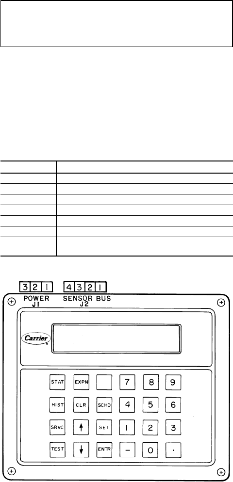
Head Pressure Control
EXV UNITS (All 30GN units except 040 and 045 with op-
tional brine) — The microprocessor controls the condenser
fans in order to maintain the lowest condensing temperature
possible, thus the highest unit efficiency. Instead of using the
conventional head pressure control methods, the fans are con-
trolled by the position of the EXV and suction superheat.
As the condensing temperature drops, the EXV opens to
maintain the proper suction superheat. Once the EXV is fully
open, if the condensing temperature continues to drop, the
suction superheat begins to rise. Once the suction superheat
is greater than 40 F (22.2 C), a fan stage is removed after
2 minutes.
As the condensing temperature rises, the EXV closes to
maintain the proper suction superheat. Once the EXV has
closed to 39.5% open (600 steps open), a fan stage is added
after 2 minutes.
During start-up, all the condenser fans are started when
the condensing temperature reaches 95 F (35 C) to prevent
excessive discharge pressure during pulldown. See Table 5
for condenser fan sequence of operation.
For low-ambient operation, the lead fan in each circuit can
be equipped with the optional or accessory Motormastert
III head pressure controller. This control has its own sensor
which is mounted on a return bend in the liquid portion of
the condenser. It will vary the fan speed to maintain a satu-
rated condensing temperature of 100 F. The controls auto-
matically default to condensing temperature control during
this first stage of condenser-fan operation. When subsequent
fan stages start, the controls revert to EXV fan control.
TXV UNITS (30GN040,045 with optional brine only) —
Head pressure control is based on set point control. The micro-
processor stages the condenser fans to maintain the set point
temperature specified by the controller.
Pumpout
EXV UNITS — When the lead compressor in each circuit
is started or stopped, that circuit goes through a pumpout
cycle to purge the cooler and refrigerant suction lines of
refrigerant.
The pumpout cycle starts immediately upon starting the
lead compressor and continues until the saturated suction tem-
perature is 10° F (5.6° C) below the saturated suction tem-
perature at start-up, is 10° F (5.6° C) below the cooler leav-
ing fluid temperature, or reaches a saturated suction temperature
of –15 F (–26 C). No pumpout is necessary if the saturated
suction temperature is below –15 F (–26 C). At this point,
the EXV starts to open and continues to open gradually to
provide a controlled start-up to prevent liquid flood-back to
the compressor.
At shutdown, the pumpout cycle continues until the satu-
rated suction temperature for that circuit is 10° F (5.5° C)
below the saturated suction temperature when pumpout is
initiated, or saturated suction temperature reaches –15 F
(–26 C). At that point, the compressor shuts down and the
EXV continues to move until fully closed.
TXV UNITS — Pumpout is based on timed pumpout. On a
command for start-up, the lead compressor starts. After
10 seconds, the liquid line solenoid opens. At shutdown, the
liquid line solenoid closes, and the lead compressor contin-
ues to run for 10 seconds before stopping.
Keypad and Display Module (Also Called HSIO
or LID) — The only function of this module is to allow
the operator to communicate with the processor. It is used to
enter configurations and set points and to read data, perform
tests, and set schedules. This device consists of a keypad
with 6 function keys, 5 operative keys, 12 numeric keys
(0 to 9, •, and -), and an alphanumeric, 8-character LCD. See
Fig. 4. See Table 6 for key usage.
IMPORTANT: When entering multiple character in-
puts beginning with a zero, a decimal point must be
entered in place of the first zero. When entering an in-
put of zero, only the decimal point need be entered.
ACCESSING FUNCTIONS AND SUBFUNCTIONS — See
Tables6-8.Table 7 shows the 6 functions (identified by
name) and the subfunctions (identified by number).
AUTOMATIC DEFAULT DISPLAY — When keypad has
not been used for 10 minutes, display automatically switches
to the rotating automatic default display. This display has
7 parts, listed below, which appear in continuous rotating
sequence.
DISPLAY EXPANSION
TUE 15:45 TODAY IS TUE, TIME IS 15:45 (3:45 PM)
LOCAL ON UNIT IN LOCAL MODE
CLOCK ON UNIT IS ON VIA CLOCK SCHEDULE
8 MODE TEMPERATURE RESET IN EFFECT
COOL 1 NUMBER OF STAGES IS 1
2 ALARMS THERE ARE 2 ALARMS
3 MINS 3 MINUTES REMAINING IN THE OFF-TO-ON
TIME DELAY
Fig. 4 — Keypad and Display Module
24
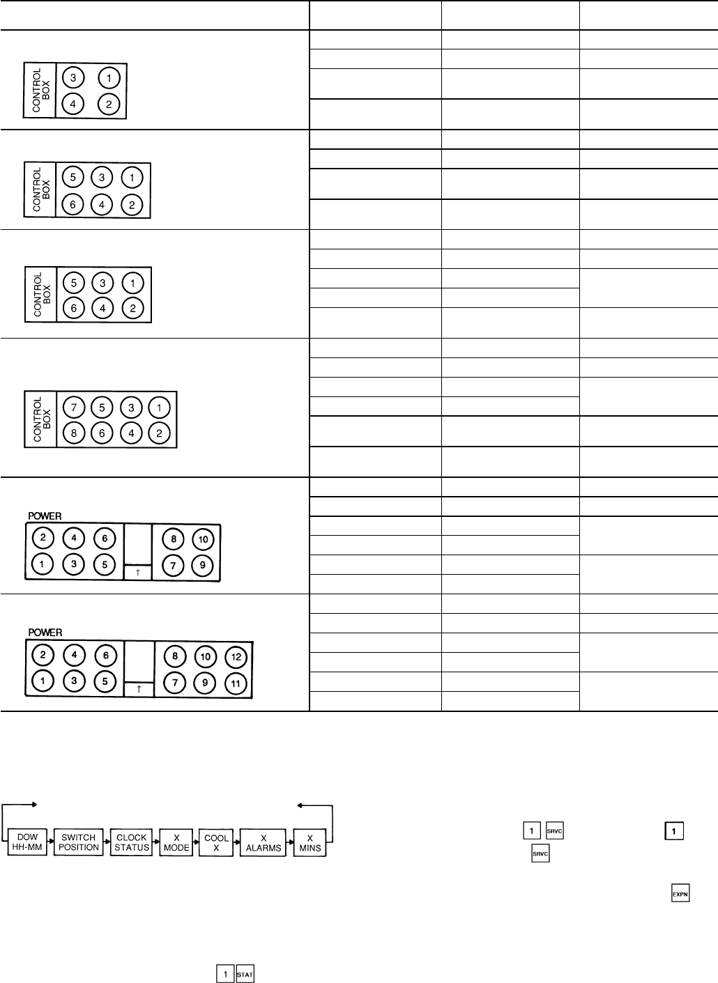
Table 5 — Condenser Fan Sequence
FAN ARRANGEMENT
30GN FAN NUMBER(S) FAN CONTACTOR
(FC) CONTROLLED BY
040-050 1 FC-A1 Compressor A1
2 FC-B1 Compressor B1
3 FC-A2 First Stage
Microprocessor
4 FC-B2 Second Stage
Microprocessor
060,070 1 FC-A1 Compressor A1
2 FC-B1 Compressor B1
3, 4 FC-A2 First Stage
Microprocessor
5, 6 FC-B2 Second Stage
Microprocessor
080,090 (and associated modular units*) 1 FC-A1 Compressor A1
2 FC-B1 Compressor B1
3 FC-A2 First Stage
Microprocessor
4 FC-B2
3, 4, 5, 6 FC-A2, FC-B2,
FC-A3, FC-B3 Second Stage
Microprocessor
100,110 (and associated modular units*) 1 FC-A1 Compressor A1
2 FC-B1 Compressor B1
3 FC-A2 First Stage
Microprocessor
4 FC-B2
5, 7, 6, 8 FC-A3, FC-B3 Second Stage
Microprocessor
3, 4, 5, 6, 7, 8 FC-A2, FC-A3,
FC-B2, FC-B3 Third Stage
Microprocessor
130-170 (and associated modular units*) 5, 7 FC-A1 Compressor A1
6, 8 FC-B1 Compressor B1
3, 9 FC-A2 First Stage
Microprocessor
4, 10 FC-B2
1, 3, 9 FC-A2, FC-A3 Second Stage
Microprocessor
2, 4, 10 FC-B2, FC-B3
190,210 (and associated modular units*) 5, 7 FC-A1 Compressor A1
6, 8 FC-B1 Compressor B1
3, 9 FC-A2 First Stage
Microprocessor
4, 10 FC-B2
1, 3, 9, 11 FC-A2, FC-A3 Second Stage
Microprocessor
2, 4, 10, 12 FC-B2, FC-B3
*See Table 1.
†Control box.
AUTOMATIC DISPLAY OPERATION/DEFAULT DIS-
PLAY — This display automatically rotates as follows:
The default rotating display is displayed every 2 seconds
if there has been no manual input from the keypad for
10 minutes.
To return to automatic display, enter at any time.
KEYPAD OPERATING INSTRUCTIONS (Refer to
Table 9.)
1. White keys on left side of keypad are shown and oper-
ated in these instructions according to the following ex-
ample: keypad entry means press the , then
the white key marked .
2. The standard display uses abbreviations. Expanded in-
formation scrolls through the display whenever key
is pressed.
DOW — Day of Week
HH — Hour(s)
MM — Minute(s)
25
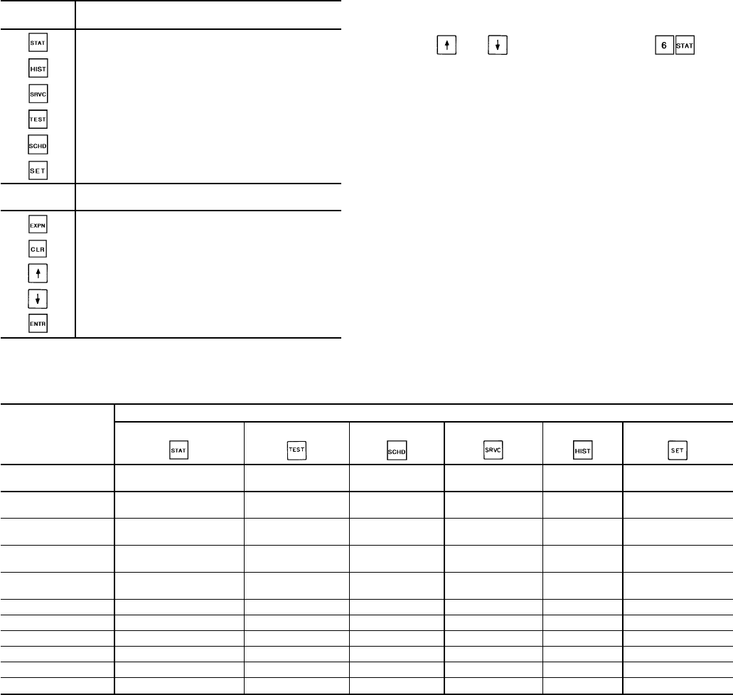
Table 6 — Keypad and Display Module Usage
FUNCTION
KEYS USE
STATUS — For displaying diagnostic codes and
current operating information about the machine.
HISTORY — For displaying run time, cycles and
previous alarms.
SERVICE — For entering specific unit configura-
tion information.
TEST — For checking inputs and outputs for
proper operation.
SCHEDULE — For entering occupied/unoccupied
schedules for unit operation.
SET POINT — For entering operating set points
and day/time information.
OPERATIVE
KEYS USE
EXPAND — For displaying a non-abbreviated ex-
pansion of the display.
CLEAR — For clearing the screen of all displays.
UP ARROW — For returning to previous display
position.
DOWN ARROW — For advancing to next display
position.
ENTER — For entering data.
3. All functions are made up of a group of subfunctions. To
enter a subfunction, first press subfunction number de-
sired. Then press the function key in which the subfunc-
tion resides. To move within that subfunction, press
the or arrow. For example, a enters
the Temperature Information subfunction.
4. At any time, another subfunction may be entered by press-
ing the subfunction number, then the function key.
5. Prior to starting unit, check leaving fluid set point for cor-
rect setting. Refer to Set Point Function section on
page 38.
6. Depending on system configuration, all displays may not
be shown. All displays are shown unless marked with the
following symbol:
†Must be configured.
For additional unit start-up procedures, see separate
Installation, Start-Up, and Service Instructions supplied
with unit.
Table 7 — Functions and Subfunctions
SUBFUNCTION
NO.
FUNCTIONS
Status Test Schedule Service History Set Point
1Automatic
Display Outputs Override Log On and
Log Off Run Time Set Points
(Chiller Fluid)
2Alarm
Display Compressors
and Unloaders Clock Select Version
(Software) Starts Reset
Set Points
3Mode (Operating)
Display Calibrate
Transducers Period 1 Factory
Configuration Alarm
History Demand Limit
Set Points
4Capacity
Stages — Period 2 Field
Configuration — Date and
Time
5Set Points
(Current Operating) — Period 3 Service
Configuration — Leaving Chiller
Fluid Alert Limit
6Temperatures — Period 4 — — —
7Pressures — Period 5 — — —
8Analog Inputs — Period 6 — — —
9Discrete Inputs — Period 7 — — —
10 Outputs — Period 8 — — —
11 — — HOLIDAYS — — —
26
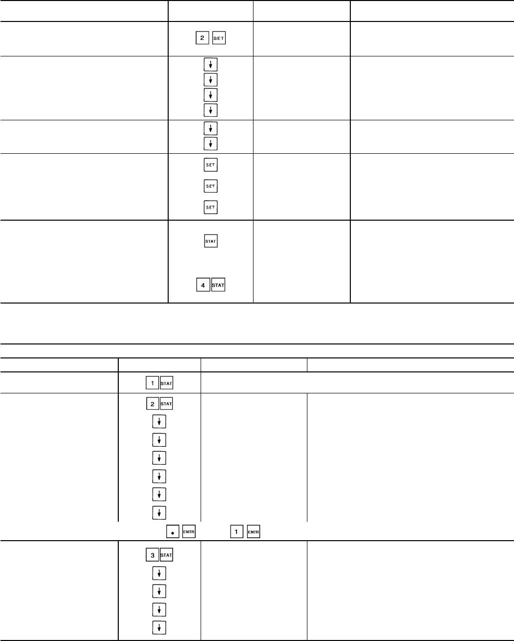
Table 8 — Accessing Functions and Subfunctions
OPERATION KEYPAD DISPLAY EXPANSION
ENTRY RESPONSE
To access a function, press
RESET RESET SETPOINTS
subfunction no. and function
name key. Display shows sub-
function group.
To move to other elements,
scroll up or down using arrow
keys. NOTE: These
displays do not show if
control is not configured
for reset.
CRT1 x COOL RESET AT 20 MA
CRT2N x COOL RTEMP (NO RESET)
CRT2F x COOL RTEMP (FULL RESET)
CRT2D x COOL DEGREES RESET
When the last element in a
subfunction has been displayed,
the first element is repeated.
RESET RESET SETPOINTS
CRT1 x COOL RESET AT 20 MA
To move to next subfunction
it is not necessary to use
subfunction number. Press
function name key to ad-
vance display through all
subfunctions within a
function and then back
to the first.
DEMAND DEMAND LIMIT SETPOINTS
TIME CURRENT TIME AND DAY OF
WEEK
SETPOINT UNIT SETPOINTS
To move to another function,
either depress function name
key for desired function
(display shows the first
subfunction),
X ALARMS THERE ARE n ALARMS
or
Access a specific sub-
STAGE CAPACITY STAGING
INFORMATION
function by using the sub-
function number and the
function name key.
Table 9 — Keypad Directory
STATUS
SUBFUNCTION KEYPAD ENTRY DISPLAY COMMENT
1 AUTOMATIC DISPLAY Refer to Automatic Display Operation/Default Display section on page 25.
2 ALARMS/ALERTS X ALARMS Number of Tripped Alarms/Alerts
R S AL Reset all Alarms/Alerts
ALARM* X }Displays Tripped Alarms/Alerts
ALARM* X
ALARM* X
ALARM* X
ALARM* X
To toggle between inputs (Yes/No) Press: (no) or (yes)
3 MODES X MODES Number of Modes in Effect
X MODE }Displays Mode in Effect
X MODE
X MODE
X MODE
27
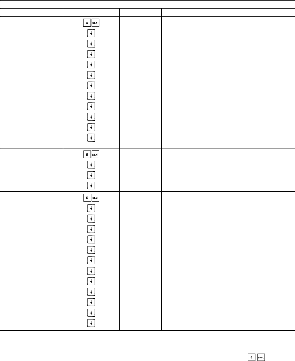
Table 9 — Keypad Directory (cont)
STATUS (cont)
SUBFUNCTION KEYPAD ENTRY DISPLAY COMMENT
4 STAGE STAGE Capacity Staging Information
COOL X Number of Requested Stages
CAPT X Percent of Total Capacity
CAPA X Percent Circuit A Total Capacity
CAPB X Percent Circuit B Total Capacity
AVAIL X Percent Available Capacity
AV A X Percent Circuit A Available Capacity
AV B X Percent Circuit B Available Capacity
LMT X† Demand Limit Set Point (percent)
CIRA X Circuit A Compressor Relay Status
CIRB X Circuit B Compressor Relay Status
SMZ X Load/Unload Factor for Compressors
Factor = 1 Unloader Factor = 0.6
5 SET POINT SETPOINT Fluid Set Point Information
SET X Set Point (F)
MSP X Modified Set Point = Set Point + Reset (F)
TW X Actual Control Temperature (F)
6 TEMPERATURE TEMPS Temperature Information (F)
EWT X Cooler Entering Fluid Temperature (F)
LWT X Cooler Leaving Fluid Temperature (F)
SCTA X Circuit A Saturated Condenser Temperature (F)
SSTA X Circuit A Saturated Suction Temperature (F)
CTA X Compressor A1 Suction Temperature (F)
SHA X Circuit A Suction Superheat (F)
SCTB X Circuit B Saturated Condenser Temperature (F)
SSTB X Circuit B Saturated Suction Temperature (F)
CTB X Compressor B1 Suction Temperature (F)
SHB X Circuit B Suction Superheat (F)
SPC X Space Temperature (F)
OAT X Outdoor-Air Temperature (F)
LEGEND
CCN — Carrier Comfort Network
EXV — Electronic Expansion Valve
MOP — Maximum Operating Pressure
*Will read ALARM or ALERT as appropriate.
†Must be configured.
**If applicable.
††Not manually resettable.
NOTE: If metric option is selected under , temperature
expressed as Celsius and pressure will be expressed as kPa.
28
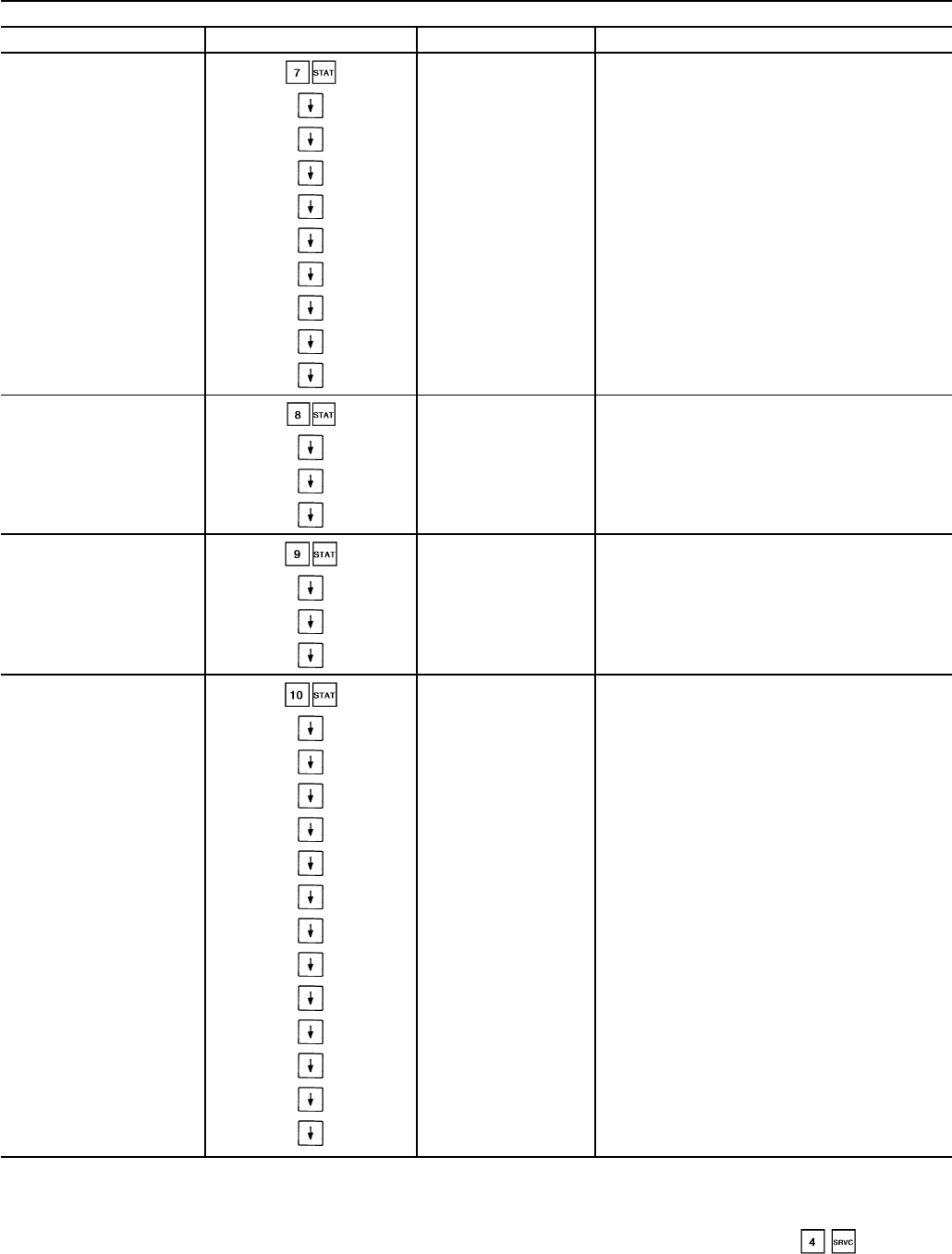
Table 9 — Keypad Directory (cont)
STATUS (cont)
SUBFUNCTION KEYPAD ENTRY DISPLAY COMMENT
7 PRESSURE PRESSURE Refrigerant System Pressure (psig)
MM DD YY Date of Last Calibration
DPA X Circuit A Discharge Pressure (psig)
SPA X Circuit A Suction Pressure (psig)
XXXX XXX Circuit A Discharge/Suction (psig)
OPA X Circuit A Oil Pressure Differential (psig)
DPB X Circuit B Discharge Pressure (psig)
SPB X Circuit B Suction Pressure (psig)
XXXX XXX Circuit B Discharge/Suction (psig)
OPB X Circuit B Oil Pressure Differential (psig)
8 ANALOG ANALOG Status of Analog Inputs
REF X Transducer Supply Voltage (volts)
LMT X† Demand 4-20 mA Signal (mA)
RST X† Reset 4-20 mA Signal (mA)
9 INPUTS SW INPUT Status of Switch Inputs
SPW X† Dual Set Point Switch (open/closed)
DL1 X† Demand Limit Switch 1 (open/closed)
DL2 X† Demand Limit Switch 2 (open/closed)
10 OUTPUTS OUTPUTS Status of Outputs
ALMR X Alarm Relay K3 (on/off)
FRA1 X Fan Relay K1 (on/off)
FRA2 X Fan Relay K2 (on/off)
FRB1 X Fan Relay K4 (on/off)
FRB2 X Fan Relay K5 (on/off)
CHWP X† Cooler Water Pump Relay K6 (on/off)
ULA1 X Unloader A1 (on/off)**
ULA2 X† Unloader A2 (on/off)**
ULB1 X Unloader B1 (on/off)**
ULB2 X† Unloader B2 (on/off)**
LLSA X Liquid Line Solenoid A
LLSB X Liquid Line Solenoid B
EXVA X EXVA Percent Open†
LEGEND
CCN — Carrier Comfort Network
EXV — Electronic Expansion Valve
MOP — Maximum Operating Pressure
*Will read ALARM or ALERT as appropriate.
†Must be configured.
**If applicable.
††Not manually resettable.
NOTE: If metric option is selected under , temperature
expressed as Celsius and pressure will be expressed as kPa.
29
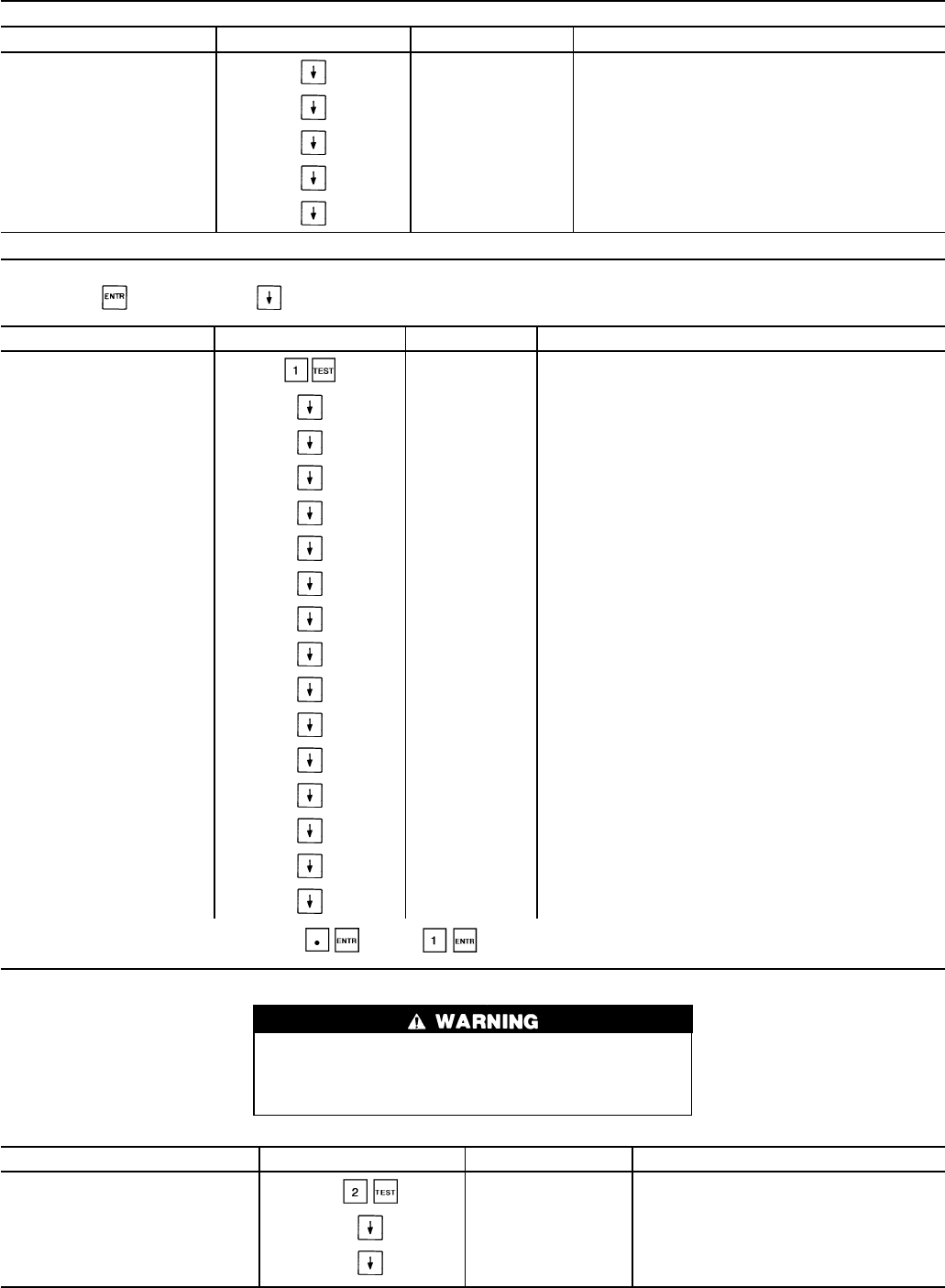
Table 9 — Keypad Directory (cont)
STATUS (cont)
SUBFUNCTION KEYPAD ENTRY DISPLAY COMMENT
10 OUTPUTS (cont) EXVB X EXVB Percent Open**
HGBA X† Hot Gas Bypass Relay Circuit A (on/off)**
HGBB X† Hot Gas Bypass Relay Circuit B (on/off)**
MMA X† MotormasterTA Output Percent**
MMB X† Motormaster B Output Percent**
TEST
To use Test function, LOCAL/ENABLE-STOP-CCN switch must be in STOP position. To operate a test, scroll to desired test.
Then, press to start test. Press to stop test.
SUBFUNCTION KEYPAD ENTRY DISPLAY COMMENT
1 OUTPUTS OUTPUTS Test Outputs
8.8.8.8.8.8.8.8 Display Check
ALMR X Energize Alarm Relay K3 (on/off)
FRA1 X Energize Fan Relay A1 K1 (on/off)
FRA2 X Energize Fan Relay A2 K2 (on/off)
FRB1 X Energize Fan Relay B1 K4 (on/off)
FRB2 X Energize Fan Relay B2 K5 (on/off)
CHWP X† Energize Cooler Water Pump K6 (on/off)
LSVA X Energize Liquid Line Solenoid A (on/off)**
LSVB X Energize Liquid Line Solenoid B (on/off)**
EXVA X Enter Desired EXVA Position (percent)**
EXVB X Enter Desired EXVB Position (percent)**
HGBA X† Energize Hot Gas Bypass Relay A (on/off)**
HGBB X† Energize Hot Gas Bypass Relay B (on/off)**
MMA X† Enter Desired Motormaster A Output Signal (percent)**
MMB X† Enter Desired Motormaster B Output Signal (percent)**
To toggle between inputs (Yes/No) Press: (no) or (yes)
SUBFUNCTION KEYPAD ENTRY DISPLAY COMMENT
2 COMPRESSORS AND
UNLOADERS COMP Compressor and Unloader Test
CPA1 X Test Compressor A1 (on/off)
CPA2 X† Test Compressor A2 (on/off)**
During compressor test, compressors start and run for
10 seconds. Compressor service valves and liquid line
valves must be open. Energize crankcase heaters 24 hours
prior to performing compressor tests.
30
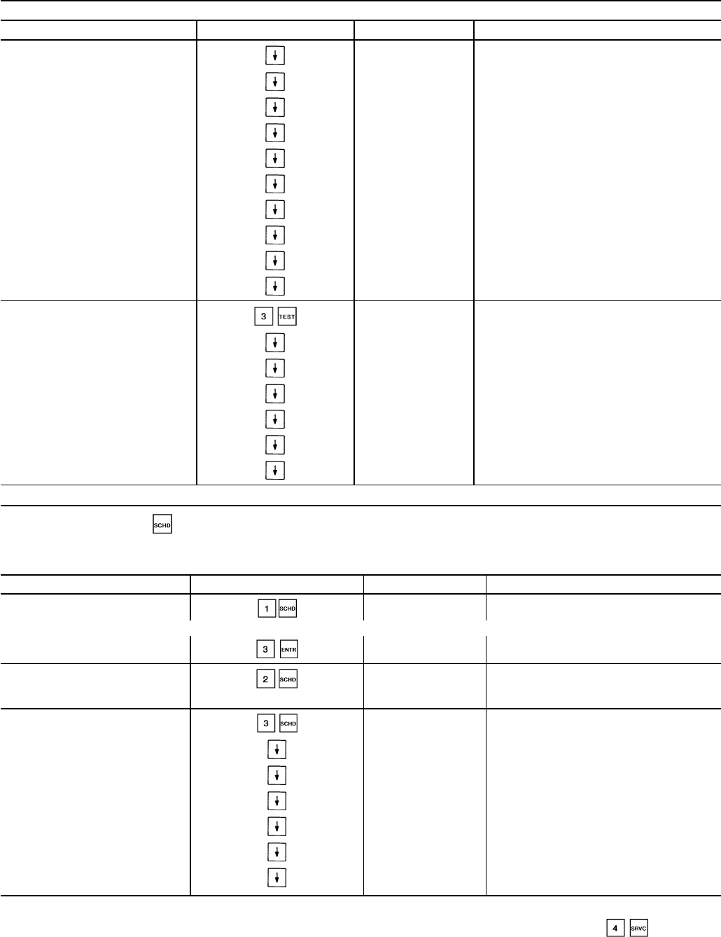
Table 9 — Keypad Directory (cont)
TEST (cont)
SUBFUNCTION KEYPAD ENTRY DISPLAY COMMENT
2 COMPRESSORS AND
UNLOADERS (cont) CPA3 X† Test Compressor A3 (on/off)**
CPA4 X† Test Compressor A4 (on/off)**
CPB1 X Test Compressor B1 (on/off)
CPB2 X† Test Compressor B2 (on/off)**
CPB3 X† Test Compressor B3 (on/off)**
CPB4 X† Test Compressor B4 (on/off)**
UNA1 X Energize Unloader A1 (on/off)**
UNA2 X† Energize Unloader A2 (on/off)**
UNB1 X Energize Unloader B1 (on/off)**
UNB2 X† Energize Unloader B2 (on/off)**
3 CALIBRATE
TRANSDUCERS XDR CAL Transducer Calibration
CDPA X Circuit A Discharge Pressure (psig)
CSPA X Circuit A Suction Pressure (psig)
COPA X Circuit A Oil Pressure (psig)
CDPB X Circuit B Discharge Pressure (psig)
CSPB X Circuit B Suction Pressure (psig)
COPB X Circuit B Oil Pressure (psig)
SCHEDULE
The Schedule function key is used to configure the occupancy schedule. The clock select subfunction can be used for
unoccupied shutdown or unoccupied setback depending on the cooling set point control configuration. The Schedule function
described is for clock 1, which is the internal clock. Password required for all subfunctions except override.
SUBFUNCTION KEYPAD ENTRY DISPLAY COMMENT
1 OVERRIDE OVRD X Number of Override Hrs (0 - 4 Hrs)
For example, to extend current occupied mode for 3 hrs, press:
OVRD 3 Extended Occupied Time
2 CLOCK SELECT CLOCK XX Type of Clock Control
0 = No Clock, 1 = Clock 1 (Internal)
3 PERIOD 1 PERIOD 1 Period 1 Time Schedule
Yes = Schedule Opera-
tional for that day OCC HH.MM Occupied Time
UNO HH.MM Unoccupied Time
MON X Monday Flag (yes/no)
TUE X Tuesday Flag (yes/no)
WED X Wednesday Flag (yes/no)
THU X Thursday Flag (yes/no)
LEGEND
CCN — Carrier Comfort Network
EXV — Electronic Expansion Valve
MOP — Maximum Operating Pressure
*Will read ALARM or ALERT as appropriate.
†Must be configured.
**If applicable.
††Not manually resettable.
NOTE: If metric option is selected under , temperature
expressed as Celsius and pressure will be expressed as kPa.
31
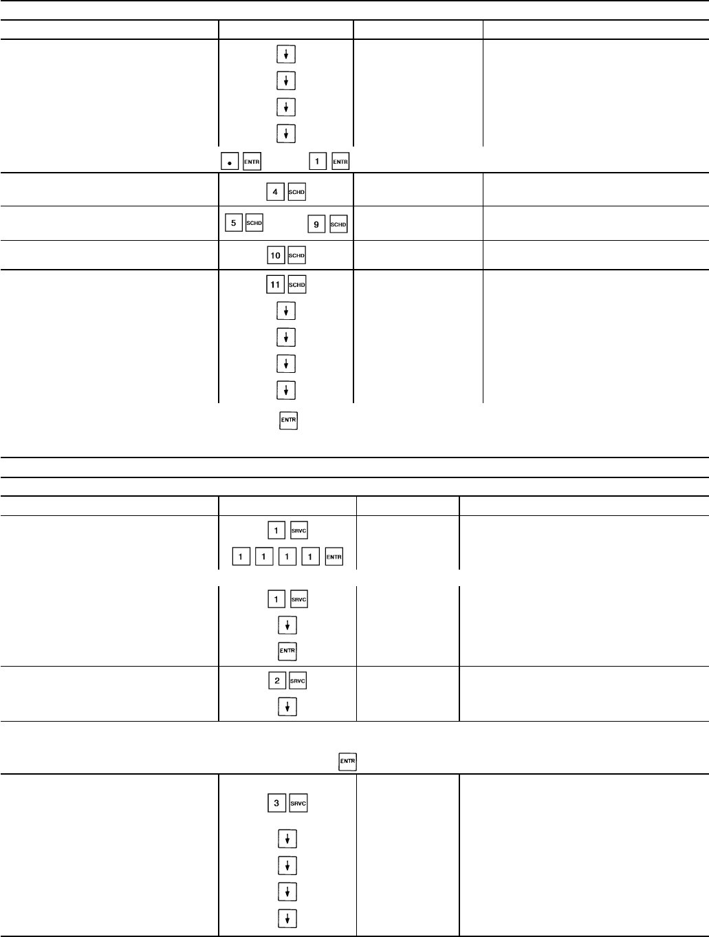
Table 9 — Keypad Directory (cont)
SCHEDULE (cont)
SUBFUNCTION KEYPAD ENTRY DISPLAY COMMENT
3 PERIOD 1 (cont) FRI X Friday Flag (yes/no)
SAT X Saturday Flag (yes/no)
SUN X Sunday Flag (yes/no)
HOL X Holiday Flag (yes/no)
To toggle between inputs (Yes/No) Press: (no) or (yes)
4 PERIOD 2 PERIOD 2 Period 2 Time Schedule
5 PERIOD 3 ... 9 PERIOD 7 ... PERIOD 3 ...
PERIOD 7 Period 3 ... Period 7 Time Schedule
10 PERIOD 8 PERIOD 8 Period 8 Time Schedule
11 HOLIDAYS HOLIDAYS Define Calendar Holidays
DAT MM.DD Holiday Date 1
New = Unassigned Holiday Date
DAT MM.DD.NN Holiday Date 30
For example: To enter July 4th holiday press: 07.04.01 . Display shows Jul 04. For further information on the Schedule function and its
operation, refer to Schedule Function section on page 44.
SERVICE
To view and modify configurations, the password must be entered under the log on subfunction.
SUBFUNCTION KEYPAD ENTRY DISPLAY COMMENT
1 LOG ON AND LOG OFF PASSWORD Enter Password/Disable Password Protection
LOGGEDON Logged On
At this time, configurations may be modified. When finished viewing and/or modifying configurations, log out as follows:
LOGGEDON —
LOG OFF Disable Password Protection
EXIT LOG Logged Off/Enable Password Protection
2 VERSION VERSION Software Information
XXXXXXXX Version No. of Software (CESRXX)
The next 3 subfunctions provide the ability to modify configurations. Refer to separate Installation, Start-Up, and Service Instructions
supplied with unit for further information on changing configurations.
To change a configuration, enter the new configuration and press while on the correct configuration.
3 FACTORY
CONFIGURATION
FACT CFG Factory Configuration Codes
XXXXXXXX Configuration Code 1
XXXXXXXX Configuration Code 2
XXXXXXXX Configuration Code 3
XXXXXXXX Configuration Code 4
32
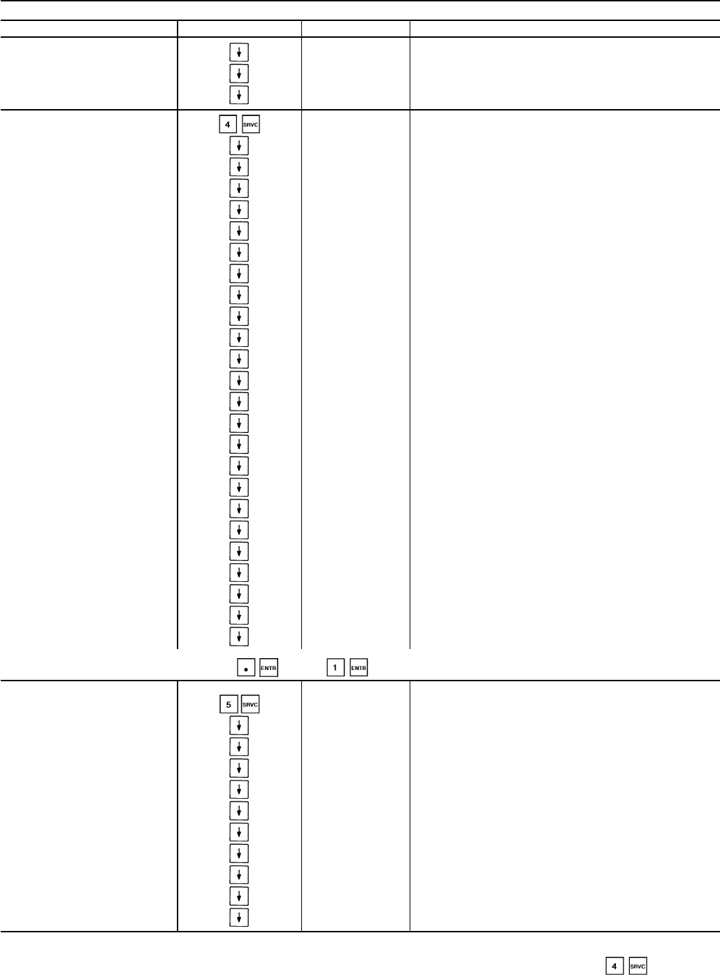
Table 9 — Keypad Directory (cont)
SERVICE (cont)
SUBFUNCTION KEYPAD ENTRY DISPLAY COMMENT
3 FACTORY
CONFIGURATION (cont) XXXXXXXX Configuration Code 5
XXXXXXXX Configuration Code 6
XXXXXXXX Configuration Code 7
4 FIELD
CONFIGURATION FLD CFG Adjustable Field Configuration
ENO X CCN Element Address
BUS X CCN Bus Number
BAUD X CCN Baud Rate
FLUID X Cooler Fluid Select (water/medium brine)
UNITS X Display Unit Select (English/Metric)
DELAY X Delay at Power Up (minutes)
NULA X No. Circuit A Unloaders
NULB X No. Circuit B Unloaders
HGB X Hot Gas Bypass Select (used, not used)
SEQT X Loading Sequence Select (equal circuit, staged circuit)
LEADT X Lead/Lag Sequence Type
OPS X Oil Pressure Switch Select (enable/disable)
HEADT X Head Pressure Control Type
(none, air cooled, water cooled)
MM X MotormasterTSelect
CSPTYP X Cooling Set Point Control Select
CRTYP X Cooling Reset Control Select
ERTYP X External Reset Sensor Select
OATSEL X Outdoor-Air Sensor Select
LSTYP X Demand Limit Control Select
RAMP X Ramp Load Select (enable, disable)
LOCK X Cooler Pump Interlock Select
CPC X Cooler Pump Control Select
REMA X Remote Alarm Option Select (yes/no)
ALRST X Allow Local/Stop/CCN Reset of Alarms (yes/no)
To toggle between inputs (Yes/No) Press: (no) or (yes)
5 SERVICE
CONFIGURATION SRV CFG Service Configurations
XXXXXXXX Configuration Code 8
XXXXXXXX Configuration Code 9
REFRIG X Refrigerant
TDTYP X Pressure Transducer Select
OPS X Oil Transducer Set Point (psig)
LPS X Low Pressure Set Point (psig)
FANTYP X Fan Staging Select
SH X EXV Superheat Set Point (F)
MOP X EXV MOP Set Point (F)
ZM X Z Multiplier
LEGEND
CCN — Carrier Comfort Network
EXV — Electronic Expansion Valve
MOP — Maximum Operating Pressure
*Will read ALARM or ALERT as appropriate.
†Must be configured.
**If applicable.
††Not manually resettable.
NOTE: If metric option is selected under , temperature
expressed as Celsius and pressure will be expressed as kPa.
33
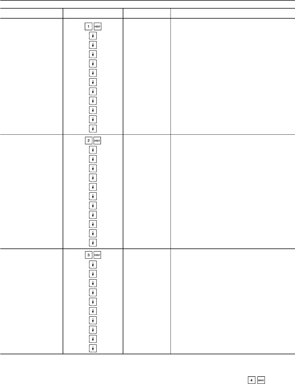
Table 9 — Keypad Directory (cont)
HISTORY
SUBFUNCTION KEYPAD ENTRY DISPLAY COMMENT
1 RUN TIME RUN TIME Run Time Information
HR X Total Hrs Unit Has a Comp Operating
HRA X Circuit A Run Time
HRB X Circuit B Run Time
HA1 X Circuit A, Comp A1 Operating Hours
HA2 X Circuit A, Comp A2 Operating Hours**
HA3 X Circuit A, Comp A3 Operating Hours**
HA4 X Circuit A, Comp A4 Operating Hours**
HB1 X Circuit B, Comp B1 Operating Hours
HB2 X Circuit B, Comp B2 Operating Hours**
HB3 X Circuit B, Comp B3 Operating Hours**
HB4 X Circuit B, Comp B4 Operating Hours**
2 STARTS STARTS Starts Information
CY X Cycles from Stage 0 to Stage 1
CYA X Circuit A Starts
CYB X Circuit B Starts
CA1 X Circuit A, Comp A1 Starts
CA2 X Circuit A, Comp A2 Starts**
CA3 X Circuit A, Comp A3 Starts**
CA4 X Circuit A, Comp A4 Starts**
CB1 X Circuit B, Comp B1 Starts
CB2 X Circuit B, Comp B2 Starts**
CB3 X Circuit B, Comp B3 Starts**
CB4 X Circuit B, Comp B4 Starts**
3 ALARM/ALERT
HISTORY†† ALRMHIST Last 10 Alarms/Alerts
ALARM X }Alarm/Alert Description
ALARM X
ALARM X
ALARM X
ALARM X
ALARM X
ALARM X
ALARM X
ALARM X
ALARM X
LEGEND
CCN — Carrier Comfort Network
EXV — Electronic Expansion Valve
MOP — Maximum Operating Pressure
*Will read ALARM or ALERT as appropriate.
†Must be configured.
**If applicable.
††Not manually resettable.
NOTE: If metric option is selected under , temperature
expressed as Celsius and pressure will be expressed as kPa.
34
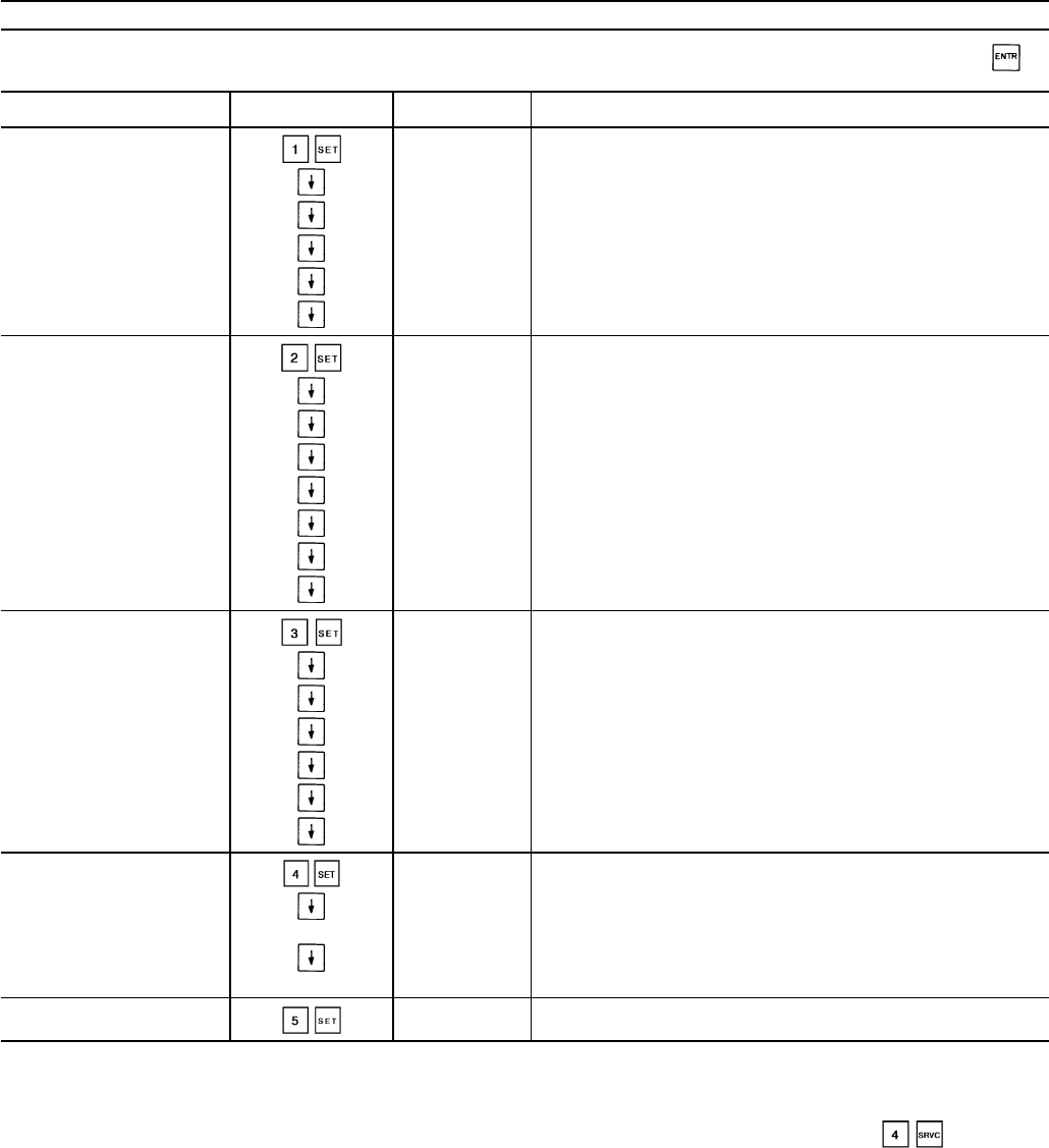
Table 9 — Keypad Directory (cont)
SET POINT
To read a set point, go to proper subfunction and read desired set point. To change a set point, enter new set point value, then press .
LOCAL/ENABLE-STOP-CCN switch must be in LOCAL/ENABLE or STOP position.
SUBFUNCTION KEYPAD ENTRY DISPLAY COMMENT
1 SET POINTS SET POINT Unit Set Point
CSP1 X Chiller Fluid Set Point 1 (F)
CSP2 X Chiller Fluid Set Point 2 (F)
HSPA X Head Pressure Set Point Circuit A (F)
HSPB X Head Pressure Set Point Circuit B (F)
CRAMP X Cooling Ramp Loading Rate (F)
2 RESET SET POINTS RESET Reset Set Points
CRT1 X Cooling reset at 20 mA (F)
CRT2N X Reference Temperature at No Reset (F)
CRT2F X Reference Temperature at Full Reset (F)
CRT2D X Total Degrees of Reset (F)
CRT3N X Chiller Fluid DT at No Reset (F)
CRT3F X Chiller Fluid DT at Full Reset (F)
CRT3D X Total Degrees of Reset (F)
3 DEMAND SET POINTS DEMAND Demand Set Points
DLS1 X† Demand Switch 1 Set Point (percent)
DLS2 X† Demand Switch 2 Set Point (percent)
DL20 X Demand Limit at 20 mA (percent)
DLGN X Loadshed Group Number
LSDD X Loadshed Demand (percent)
TIME X Minimum Loadshed Time (minutes)
4 DATE AND TIME DATE.TIME Date, Time and Day of Week
DOW.HR.MIN Day1=Mon,2=Tues...7=Sun
Hours are displayed in 24-hr time. Decimal point serves as colon.
MM.DD.YR Month.Day.Year. When entering date, enter a decimal
point between entries. Each entry must be two numbers.
5 LEAVING CHILLER
FLUID ALERT LIMIT LMT X Leaving Chiller Fluid Alert Limit (F)
LEGEND
CCN — Carrier Comfort Network
EXV — Electronic Expansion Valve
MOP — Maximum Operating Pressure
*Will read ALARM or ALERT as appropriate.
†Must be configured.
**If applicable.
††Not manually resettable.
NOTE: If metric option is selected under , temperature
expressed as Celsius and pressure will be expressed as kPa.
35
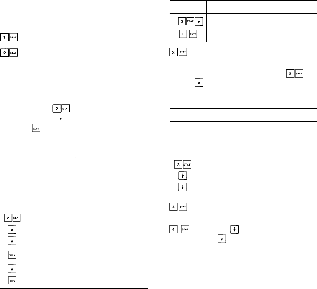
STATUS FUNCTION — This function shows the rotating
display, current status of alarm and alert (diagnostic) codes,
capacity stages, operating modes, chilled water set point, all
measured system temperatures and pressures, superheat val-
ues, pressure switch positions, analog inputs, and switch in-
puts. These subfunctions are defined on pages 36 and 37.
(Rotating Display)
(Alarms/Alerts) — Alarms and alerts are messages
that one or more faults have been detected. Each fault is as-
signed a code number which is reported with the alarm or
alert. See Table 10 for code definitions. The codes indicate
failures that cause the unit to shut down, terminate an option
(such as reset) or result in the use of a default value as set
point.
Up to 10 codes can be stored at once. To view them
in sequence, press to enter the alarm/alert dis-
plays and then press to move to the individual dis-
plays. Press after a code has been displayed. The mean-
ing of the code scrolls across the screen. See Example 1.
Example 1 — Reading Alarm Codes
KEYPAD DISPLAY COMMENTS
ENTRY RESPONSE
TUE 12:45
LOCAL ON
CLOCK ON
13 MODE
8 MODE
COOL 1
2 ALARMS
3 MINS
Keypad has not been used for
at least 10 minutes. Alternating
summary display appears on
screen
2 ALARMS 2 alarms/alerts detected
RSAL DSB Reset all alarms/alerts
ALARM 9 First alarm/alert code
COOLER LEAVING
FLUID THERMISTOR
FAILURE Explanation of alarm/alert code
ALARM 42 Second alarm/alert code.
Cooler freeze protection
COOLER FREEZE
PROTECTION Explanation of alarm/alert code
When a diagnostic (alarm or alert) code is stored in the
display and the machine automatically resets, the code is de-
leted. Codes for safeties which do not automatically reset
are not deleted until the problem is corrected and either the
machine is switched to STOP position, then back to LOCAL/
ENABLE or CCN position, or by using the keypad and dis-
play module.
To reset alarms/alerts using keypad and display module:
KEYPAD
ENTRY DISPLAY
RESPONSE COMMENTS
RSAL DSB Reset all alarms/alerts
function disabled
RSAL ENB Reset all alarms/alerts
function enabled
(Modes) — The operating mode codes are dis-
played to indicate the operating status of the unit at a given
time. See Table 10.
To enter the MODES subfunction, press and
press the key to determine if more than one mode ap-
plies. See Example 2 to read current mode with expansion.
Example 2 — Reading Current Operating Modes
KEYPAD DISPLAY COMMENTS
ENTRY RESPONSE
TUE 15:45
LOCAL ON
CLOCK ON
8 MODE
COOL 1
0 ALARMS
3 MINS
Keypad has not been used for at
least 10 minutes. Rotating summary
display appears on screen
2 MODES There are 2 modes currently in effect
LOCAL ON Unit is on by chiller on/off switch
8 MODE Temperature reset is in effect
(Stage) — This subfunction displays the capac-
ity stage number. See Tables 4A-4C for compressor loading
sequence. To enter the STAGE subfunction, press
and press the to display the stage number.
Continue pressing for the following information:
• Number of requested stages.
• Percent of total unit capacity being utilized.
• Percent of each circuit capacity being utilized.
• Percent of total capacity available.
• Percent of capacity available in each circuit.
• Demand limit set point in effect (can be any value be-
tween 0% and 100%).
• Status of each compressor relay. When a compressor is
on, the number of that compressor is displayed. If a com-
pressor is off,a0isdisplayed. For example: In a given
circuit, if compressors 1 and 3 are running, and 2 and 4 are
not running, 0301 is displayed for that circuit.
• Load/Unload factor for compressors. This factor is an in-
dication of when a step of capacity is added or subtracted.
Its value can range from slightly less than –1.0 to slightly
more than +1.0. When load/unload factor reaches +1.0, a
compressor is added. When the load/unload factor reaches
–1.0, a compressor is subtracted. If compressor unloaders
are used, at –.6 a compressor is unloaded and at +.6, a
compressor is loaded up.
36
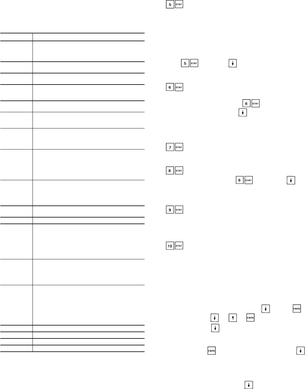
Table 10 — Operational and Mode Display Codes
The operating modes are displayed by name or code num-
ber, to indicate the operating status of the unit at a given
time. The modes are:
CODE DESCRIPTION
LOCAL OFF
Unit is off. LOCAL/ENABLE-STOP-CCN switch is in
OFF position, or LOCAL/ENABLE-STOP-CCN switch
may be in LOCAL position with external ON/OFF
switch in OFF position.
CCN OFF Unit is off due to CCN network command. LOCAL/
ENABLE-STOP-CCN switch is in CCN position.
CLOCK OFF Unit is off due to internal clock schedule. LOCAL/
ENABLE-STOP-CCN switch is in LOCAL position.
LOCAL ON Unit is on. LOCAL/ENABLE-STOP-CCN switch is in
LOCAL position. If external ON/OFF switch is used,
it will be in ON position.
CCN ON Unit is on due to CCN command. LOCAL/ENABLE-
STOP-CCN switch is in CCN position.
CLOCK ON Unit is on due to internal clock schedule or occu-
pied override function. LOCAL/ENABLE-STOP-
CCN switch is in LOCAL/ENABLE position.
MODE 7
Dual set point is in effect. In this mode, unit contin-
ues to run in unoccupied condition, but leaving fluid
set point is automatically increased to a higher level
(CSP2 set point is in SET function).
MODE 8
Temperature reset is in effect. In this mode, unit is
using temperature reset to adjust leaving fluid set
point upward, and unit is currently controlling to the
modified set point. The set point can be modified based
on return fluid, outdoor-air temperature, or space tem-
perature.
MODE 9
Demand limit is in effect. This indicates that ca-
pacity of unit is being limited by demand limit control
option. Because of this limitation, unit may not
be able to produce the desired leaving fluid
temperature.
MODE 10 Flotronic™ System Manager (FSM) is controlling the
chiller.
MODE 11 Not applicable.
MODE 12
Ramp load (pulldown) limiting is in effect. In this mode,
the rate at which leaving fluid temperature is dropped
is limited to a predetermined value to prevent com-
pressor overloading. See CRAMP set point in the
SET function in Table 9. The pulldown limit can be
modified, if desired, to any rate from .2 F to 2 F
(.1° to 1° C)/minute.
MODE 13
Timed override is in effect. This isa1to4hour tem-
porary override of the programmed schedule, forc-
ing unit to occupied mode. Override can be imple-
mented with unit under LOCAL/ENABLE or CCN
control. Override expires after each use.
MODE 14
Low cooler suction protection is in effect. In this mode,
circuit capacity is not allowed to increase if cooler
saturated suction temperature is 20° F (11° C) for
fluid or 30° F (16° C) for brine or more below leaving
fluid temperature, and saturated suction tempera-
ture is less than 32 F (0° C). If these conditions per-
sist beyond 10 minutes, circuit is shut down and fault
code 44 or 45 is displayed.
MODE 15 Water System Manager is controlling the chiller.
MODE 16 Slow change override is in effect.
MODE 17 X minute off-to-on delay is in effect.
MODE 18 Low suction superheat protection is in effect.
CCN — Carrier Comfort Network
(Set Point) — This subfunction displays leaving
fluid temperature and leaving chilled fluid set point. If unit
is programmed for dual set point, the chilled fluid set point
currently in effect (either occupied or unoccupied) is
displayed. If reset is in effect, the unit operates to the modi-
fied chilled fluid set point. This means the leaving fluid tem-
perature may not equal the chilled fluid set point. The
modified chilled fluid set point can also be displayed in the
Status function. To enter the set point subfunction,
press and press to display the set point fol-
lowed by the modified leaving chilled fluid set point and ac-
tual control temperature.
(Temperature) — The temperature subfunction dis-
plays the readings at temperature sensing thermistors.
To read a temperature, enter , then scroll to de-
sired temperature using the key. See Table 9 for the
order of readouts. This subfunction also displays the satu-
rated refrigerant temperatures corresponding to the suction
and discharge pressures measured by the compressor
transducers.
(Pressure) — This subfunction displays suction,
discharge, and net oil pressure at lead compressor of each
circuit of unit.
(Analog Inputs) — This subfunction displays
analog inputs, if any. Press , then press . The
transducer supply voltage, 4-20 mA reset signal can be dis-
played. This is useful for problem diagnosis prior to using
the test function.
(Discrete Inputs) — This subfunction displays sta-
tus (open/closed) of discrete input switch where applicable.
Status of dual set point switch and demand limit switches 1
and 2 can be displayed. This is useful for problem diagnosis
prior to using the test function.
(Outputs) — This function displays on/off sta-
tus of alarm relay, all fan relays, and chilled water pump
relay. It also displays on/off status of compressor unloaders
(if used). The position of each EXV (in percent open) can be
displayed.
TEST FUNCTION — The test function operates the diag-
nostic program. To initiate test function, the LOCAL/
ENABLE-STOP-CCN switch must be in STOP position.
To reach a particular test, press its subfunction number,
then scroll to desired test by pressing . Press to
start a test. Press or or to terminate or exit a
test. Pressing the key after a test has started advances
system to next test, whether current test is operating or has
timed out. Once in the next step, you may start
test by pressing or advance past it by pressing .
While the unit is in test, you may leave test function and
access another display or function by pressing appropriate
keys. However, a component that is operating when an-
other function is accessed remains operating. You must
re-enter test function and press to shut down the com-
ponent. Components with a timed operating limit time out
normally even if another function is accessed.
37
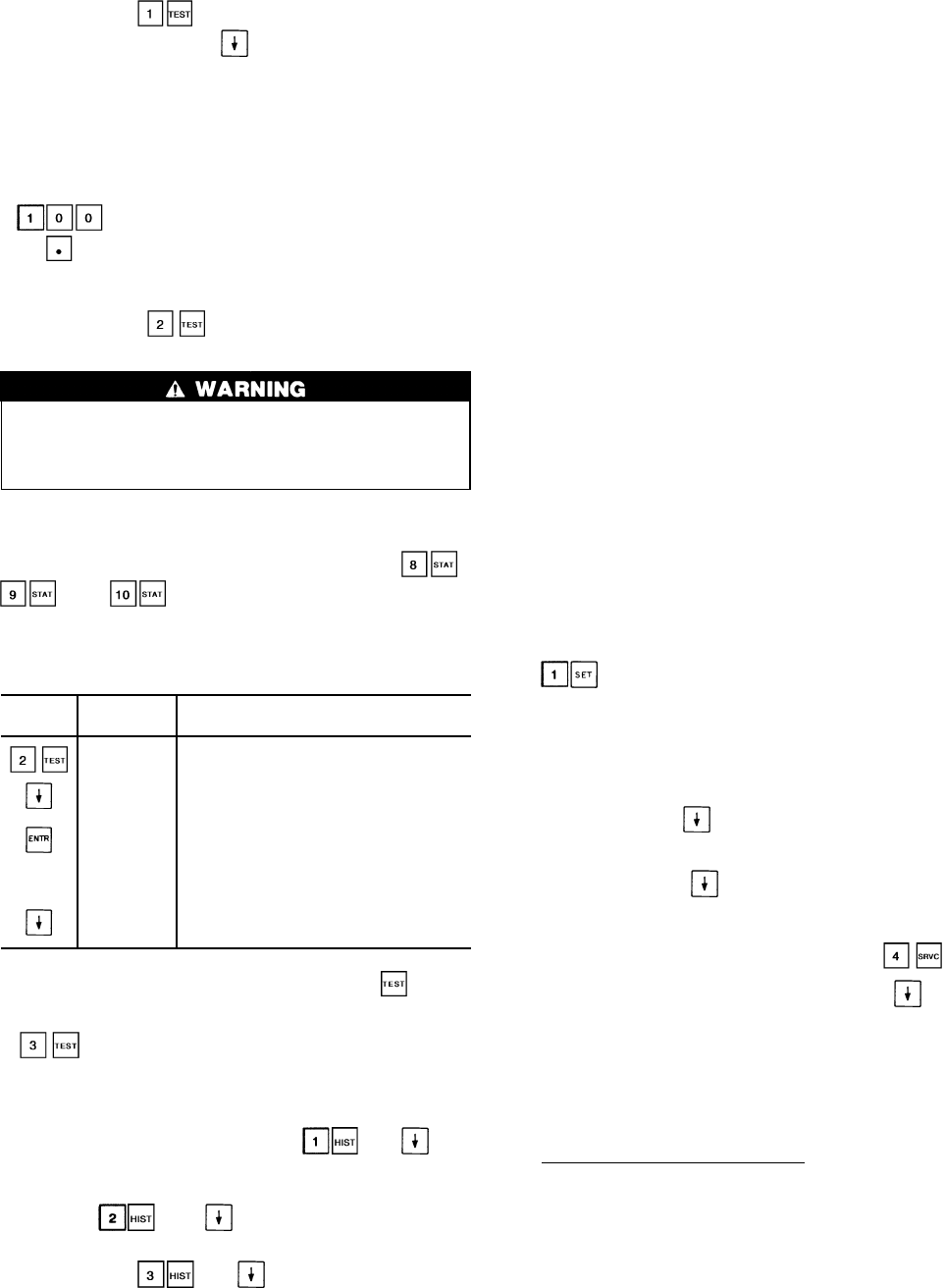
Keypad entry allows the operator to make the
following checks by using :
• LID display check. Proper display is 8.8.8.8.8.8.8.8.
• Operation of alarm relay.
• Operation of condenser fans.
• Operation of chilled fluid pump.
• Operation of liquid line solenoids.
• Operation of the hot gas bypass relays.
• Operation of EXVs. To drive EXV fully open, enter
(100% open). To drive EXV fully closed, en-
ter (0% open).
• Operation of each remote alarm.
• Operation of Motormastertsignals.
Keypad entry accesses the compressor and
compressor unloader operational tests.
During compressor operational tests, compressor starts
and runs for 10 seconds. Compressor service valves must
be open. Energize crankcase heaters 24 hours prior to
performing compressor tests.
Since test function checks only certain outputs, it is good
practice to also check all inputs and outputs accessible
through the status function. These are located at ,
, and (see Table 9). If keypad is not used
for 10 minutes, unit automatically leaves test function and
resumes rotating display. See Example 3.
Example 3 — Using Test Function
KEYPAD DISPLAY COMMENTS
ENTRY RESPONSE
COMP Factory/field test of compressors
subfunction of test function
CPA 1 OFF Circuit A, Compressor 1A test
CPA 1 ON Pressing ENTR starts the test:
when the compressor should be running
the display shows CPA1 on
CPA 1 OFF If the test is allowed to time out (10 sec-
onds) the display will show CPA1 off
CPA 2 OFF Pressing the down arrow key advances the
system to Circuit A, compressor 2 test
NOTE: Once a compressor has been run using the function,
it is not allowed to run again for 30 seconds.
accesses the transducer calibration subfunction.
All transducers must be calibrated in order for the unit to
operate. Refer to Pressure Transducers section on page 60
for calibration procedure.
HISTORY FUNCTION — Pressing and dis-
plays total unit run time, total run time for each circuit, and
total run time for each compressor.
Pressing and displays total unit starts, the
total starts for each circuit, and total starts for each com-
pressor. Pressing and displays the last 10 alarms
along with a description of each alarm.
SET POINT FUNCTION — Set points are entered through
the keypad. Set points can be changed within the upper and
lower limits, which are fixed. The ranges are listed below.
Chilled Fluid Set Point
Water:
38 to 86 F (3.3 to 30 C)
Medium Brine:
14 to 86 F (–10 to 30 C)
Pulldown Set Point
0.2 to 2.0 F (0.11 to 1.1 C)/min.
Reset Set Points
Maximum Reset Range:
–30° to 30° F (–17° to 17° C)
External Temperature Reset –40 to 240 F
(–40 to 118 C)
Chiller Fluid DT: 0° to 15° F
(0° to 8° C)
External Signal Reset 4 to 20 mA
Demand Limit Set Points
Switch Input:
Step1—0to100% Capacity Reduction
Step2—0to100% Capacity Reduction
External Signal:
Maximum Demand Limit 4 to 20 mA
Minimum Demand Limit 4 to 20 mA
Loadshed Demand Delta: 0 to 60%
Maximum Loadshed Time: 0 to 120 min.
Set points are grouped in subfunctions as follows:
Subfunction displays chiller fluid set points.
a. The first value shown is the occupied chilled fluid set
point.
b. The next value displayed depends on how the sched-
ule function has been programmed. (See pages 44-
47.) If dual set point has been selected, the next set
point after has been pressed is the second chilled
fluid set point. If single set point or inactive sched-
ule has been selected in the schedule function,
then when is pressed, the display shows the
head pressure set points, one for each circuit. These
are utilized only if the set point controlled method of
head pressure control is selected in .
c. The final value displayed when the is pressed
is the cooling ramp loading rate. This is the maximum
rate at which the leaving chilled fluid is allowed to
drop, and can be field set from 0.2 to 2.0 F (.11° to
1.1° C)/minute. This value is not displayed unless the
function is enabled (see Adjustable Field Configura-
tions on page 44).
Reading and Changing Set Points — Example 4 shows how
to read and change the chilled fluid set point. Other set points
can be changed by following the same procedure. Refer to
Table 9 for the sequence of display of set points in each sub-
function.
38
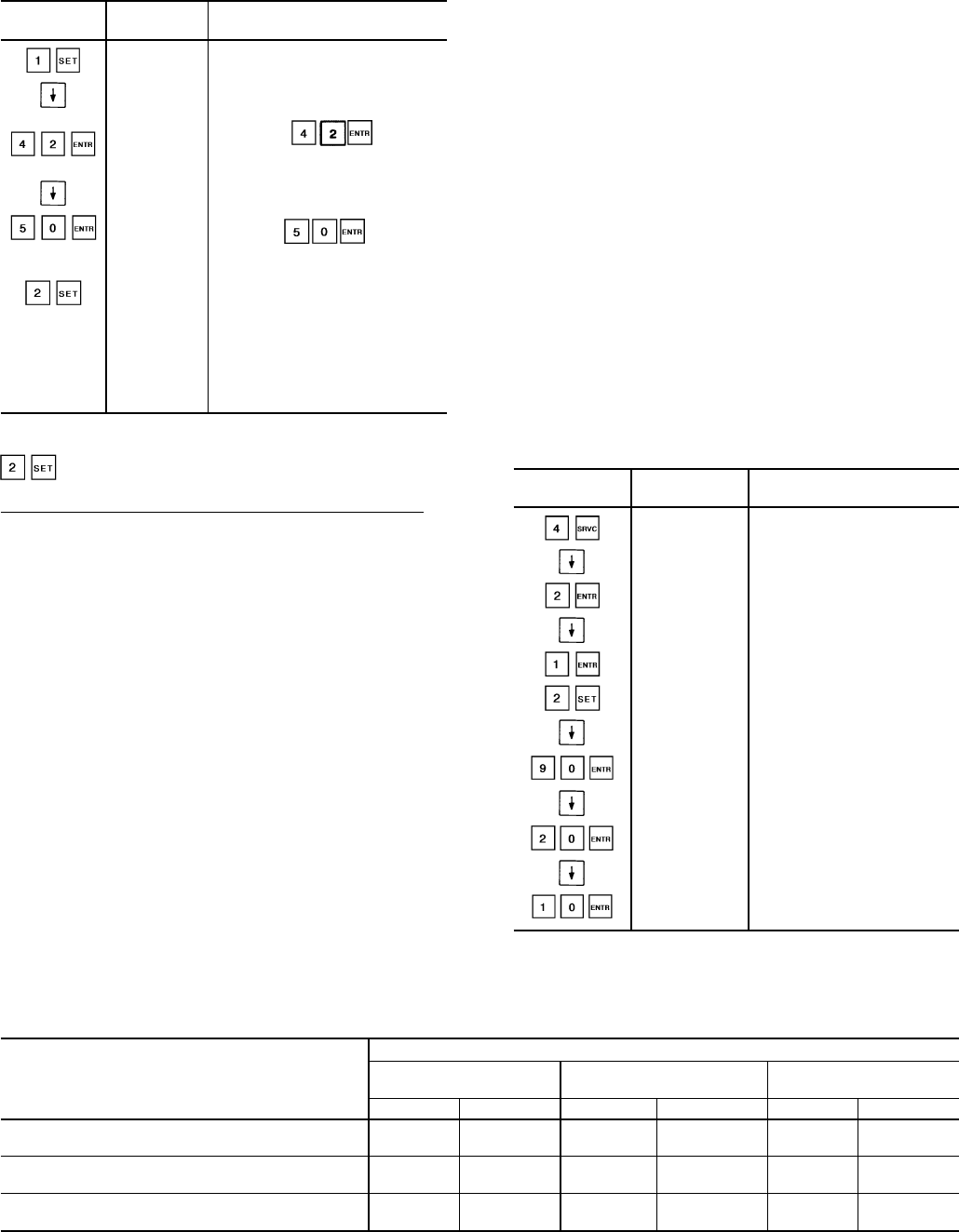
Example 4 — Reading and Changing
Chilled Fluid Set Point
KEYPAD DISPLAY COMMENTS
ENTRY RESPONSE
SET POINT System set points
CSP1 44.0 Present occupied chilled fluid
set point is 44.0 F
CSP1 42.0 Press the .
Display shows new occupied
chilled fluid set point is 42.0 F
CSP2 44.0 Present unoccupied chilled fluid
set point is 44.0 F
CSP2 50.0 Press the . Display
shows new unoccupied chilled
fluid set point is 50.0 F
RESET Displays the maximum reset
set point. The minimum and
maximum reference reset
set points can also be displayed.
These set points are not
accessible when reset type has
been configured for NONE in
the service function.
Subfunction displays temperature reset set points.
Temperature Reset Based on Return Fluid Temperature —
The control system is capable of providing leaving fluid tem-
perature reset based on return fluid temperature. Because the
temperature difference between leaving and return tempera-
ture is a measure of the building load, return fluid tempera-
ture reset is essentially an average building load reset method.
Under normal operation, the chiller maintains a constant
leaving fluid temperature approximately equal to chilled fluid
set point. As building load drops from 100% down to 0%,
entering cooler fluid temperature drops in proportion to load.
Thus, temperature drop across the cooler drops from a typi-
cal 10 F (5.5 C) at full load to a theoretical 0° F (0° C) at no
load. See Fig. 5.
At partial load, leaving chilled fluid temperature may be
lower than required. If this is allowed to increase (reset), the
efficiency of the chiller increases. Amount of reset can be
defined as a function of cooler temperature drop, as shown
in Fig. 5. This is a simple linear function that requires
3 pieces of input data for the set function that will vary de-
pending on measurement method used as follows (see
Table 11):
NOTE: Reset set points are not accessible unless the reset
function is enabled first. This is done as a field
configuration. Select one of the 4 choices for type of reset:
Return Fluid Reset, External Temperature Reset, 4-20 mA
External Signal Reset, or 4-20 mA Internal Signal Reset.
If dual set point control is enabled (see Field Wiring sec-
tion on page 69), the amount of reset is applied to whichever
set point is in effect at the time.
Examples 5A-5C demonstrate how to activate reset. Ex-
ample 6 demonstrates how to change the type of reset. As-
sume that reset is to be based on return fluid temperature,
the desired reset range is to be 0° to 10° F (0° to 5.5° C) and
full load is a 10° F (5.5° C) drop across the cooler. See
Fig. 5.
Activating reset based on external temperature or
4-20 mA signal is done the same way, except the reference
set point range is –40° to 240° F (–40° to 115° C), or 4 to
20 mA depending on which method was selected at the field
configuration step.
Example 5A — External Reset
In this example, the unit set point is reset from full load
at 90 F (32 C) to a maximum reset value of 10 F (5.5 C) at
20 F (–6.7 C) outdoor ambient.
NOTE: All temperatures given in this example are in F.
KEYPAD DISPLAY COMMENTS
ENTRY RESPONSE
FLD CFG
CRTYP 0 Scroll past to reset type
CRTYP 2 External reset selected
ERTYP 0 Scroll past to space
thermistor sensor selected
ERTYP 1 OAT selected
RESET
CRT2N 0 Temperature for no
reset is 0
CRT2N 90 Temperature for no
reset is 90
CRT2F 0 Temperature for maximum
reset is 0
CRT2F 20 Temperature for maximum
reset is 20
CRT2D 0 Maximum reset is 0
CRT2D 10 Maximum reset is 10
Table 11 — Reset Amounts
INPUT DATA DESCRIPTION
MEASUREMENT METHOD
4-20 mA OAT/Occupied Space
or Internal/External Return Water
Variable Limits (F) Variable Limits (F) Variable Limits (F)
Maximum Reset Amount — Allowable range for
maximum amount which LWT is to be reset. CRT1 –30 to 30 CRT2D –30 to 30 CRT3D –30 to 30
Maximum Reset Reference — Temperature at
which maximum reset occurs. — — CRT2F –40 to 240 CRT3F 0 to 15
Minimum Reset Reference — Temperature at
which no reset occurs. — — CRT2N –40 to 240 CRT3N 0 to 15
LEGEND
OAT — Outdoor-Air Temperature
LWT — Leaving Fluid Temperature
39
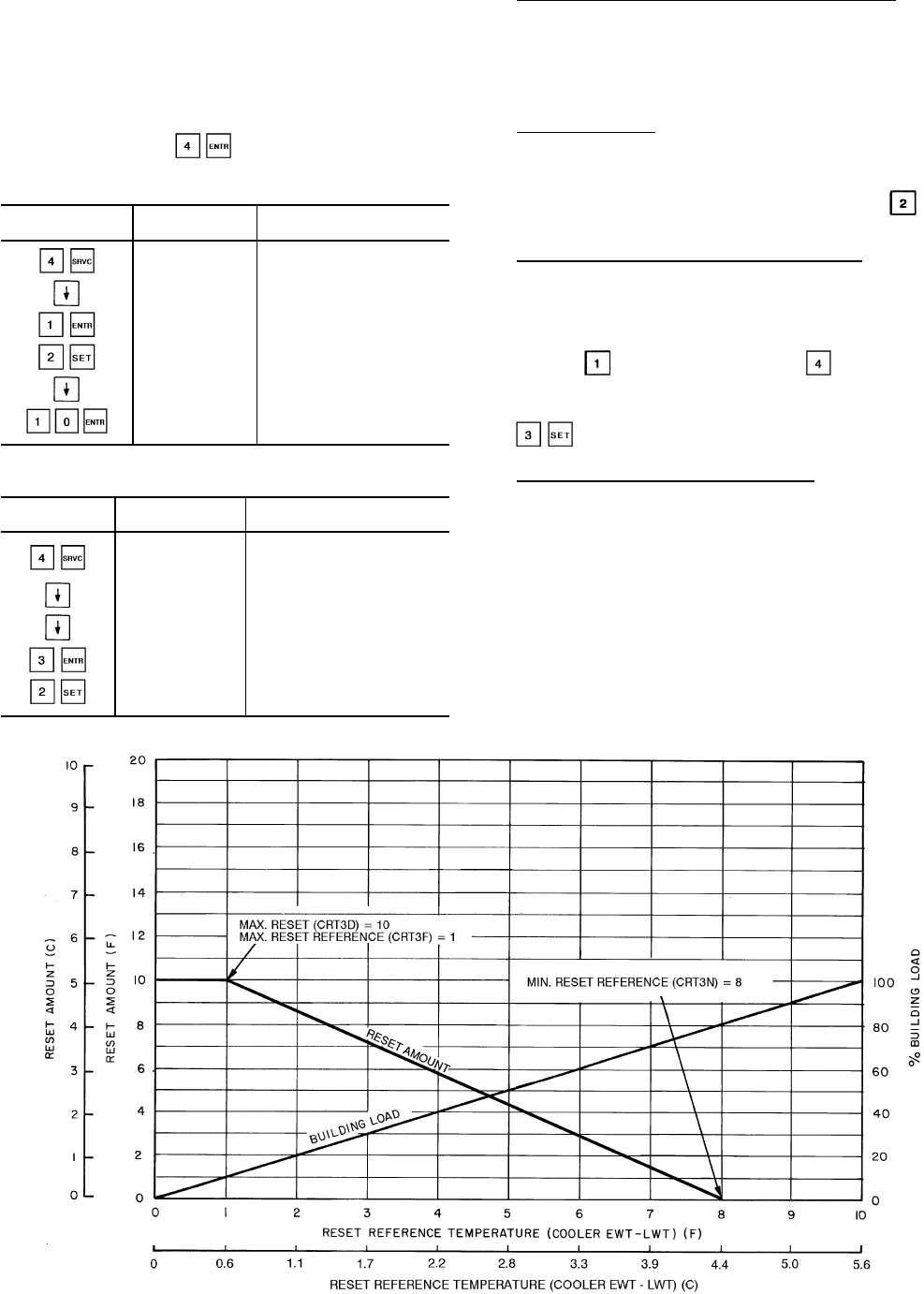
Example 5B—4to20mAandInternally or
Externally Powered Reset
In this example, the unit set point is reset from full load
at 4 mA to a maximum reset value of 10 F (5.5 C) at
20 mA. Internally powered 4 to 20 mA option is used in this
example.
NOTE: To use externally powered reset, when CRTYP
appears, press so CRTYP 4 appears in the
display. The remainder of the information in the fol-
lowing example applies to either type of reset.
KEYPAD
ENTRY DISPLAY
RESPONSE COMMENTS
FLD CFG
CRTYP 0 Scroll past to reset type
CRTYP 1 Internally powered reset
selected
RESET
CRT1 0 Reset at 20 mA is 0
CRT1 10 Reset at 20 mA is 10
Example 5C — Using Return Fluid
Temperature Reset
KEYPAD DISPLAY COMMENTS
ENTRY RESPONSE
FLD CFG Field configuration
subfunction of
service function
CSPTYP X Scroll past single/dual
CRTYP 0 Display shows no reset
type has been selected
CRTYP 3 Return fluid temperature
is selected and activated
RESET Reset set points
Temperature Reset Based on External Temperature — If de-
sired, temperature reset can be based on an external tem-
perature, such as space or outdoor-air temperature. This re-
quires a thermistor (T10, Part No. 30GB660002) located in
the space or outdoor air and wired to terminals as follows
(also see Field Wiring section on page 69 and Fig. 6):
4 in/4 out Module — J7-15 and J7-16.
At the field configuration step, enter set points as de-
scribed in Examples 5A-5C on pages 39 and 40. Then
select external temperature reset by entering when
CRTYP 0 appears. See Fig. 7.
Temperature Reset Based on 4-20 mA Signal— If desired,
temperature reset can be based on a 4-20 mA signal. For
proper connections, refer to Field Wiring section on
page 69 and Fig. 8.
At the field configuration step, select 4-20 mA reset by
entering (internally powered) or (externally pow-
ered) when CRTYP 0 appears. Then enter set points as de-
scribed previously in Examples 5A-C. See Fig. 8.
Subfunction displays demand limit set points.
Demand Limit, 2-Stage Switch Control — This control has
been designed to accept demand limit signals from a build-
ing load shedding control. The demand limit function pro-
vides for 2 capacity steps. The keypad is used to set the 2
demand limit set points, which range from 100 to 0% of ca-
pacity. Capacity steps are controlled by 2 field-supplied re-
lay contacts connected to the designated chiller terminals.
(See Field Wiring section on page 69 and Fig. 7.)
Fig. 5 — Cooling Return Fluid Reset
40
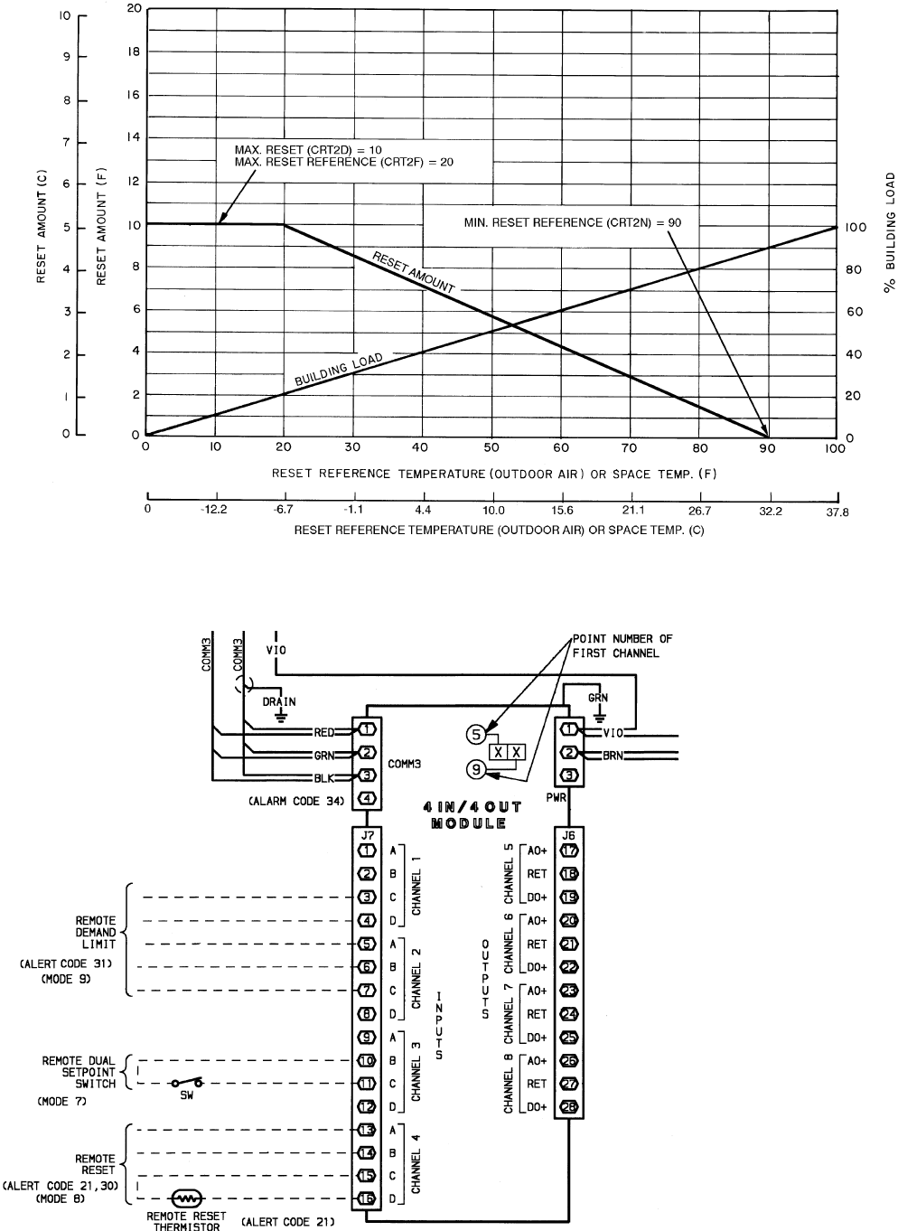
Fig. 6 — Cooling External Temperature Reset
LEGEND
COMM — Communications Bus
PWR — Power
SW — Switch
NOTE: For specific connection points,
see Fig. 25 - 29.
Fig.7—4IN/4 OUT Options Module Wiring for Reset, Demand Limit, and Dual Set Point
41
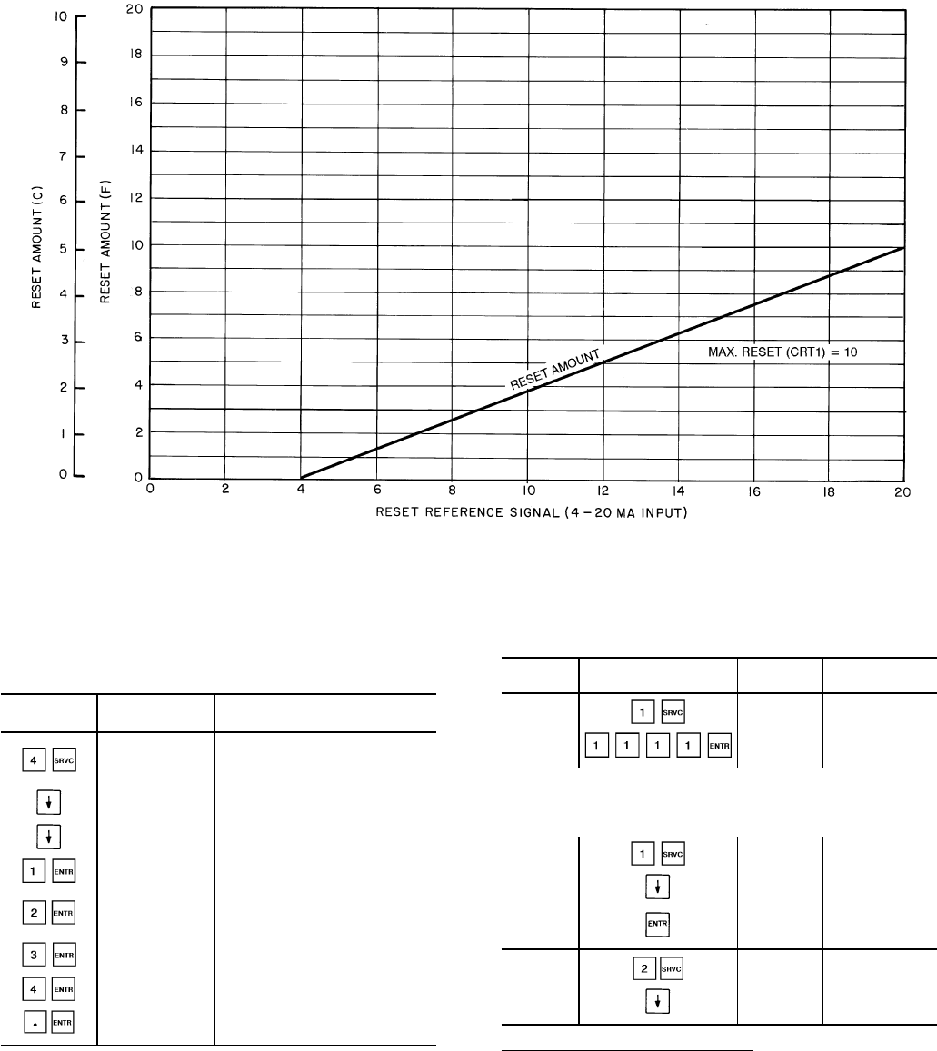
Example 6 — Changing Reset Type
To change type of reset, first log on as shown in
Table 12. Also refer to Set Point Function section, page 38,
for information on entering reset set points using reset
feature.
KEYPAD DISPLAY COMMENTS
ENTRY RESPONSE
FLD CFG Field configuration
subfunction of
service function
CSPTYP 0 Scroll past single cooling
set point
CRTYP 0 No reset has been
selected
CRTYP 1 Internally powered 4-20 mA
signal reset is selected
CRTYP 2 Space or outdoor-air
temperature reset is
selected
CRTYP 3 Return fluid temperature
reset is selected
CRTYP 4 Externally powered 4-20 mA
signal reset is selected
CRTYP 0 Reset is deactivated
To use Demand Limit, first enable loadshed, then enter
demand limit set points. See Example 7A. Closing the first
stage demand limit contact puts unit on the first demand limit
level, that is, the unit does not exceed the percentage of ca-
pacity entered as demand limit stage 1. Closing contacts on
second-stage demand limit relay prevents unit from exceed-
ing capacity entered as demand limit stage 2. The demand
limit stage that is set to the lowest demand takes priority if
both demand limit inputs are closed.
The demand limit function must be enabled in order to
function and may be turned off when its operation is not de-
sired. The demand limit relays can, in off condition, remain
connected without affecting machine operation.
Table 12 — Service Functions
To view and modify configurations, the password must be
entered under the log on subfunction.
SUB- KEYPAD DISPLAY COMMENT
FUNCTION ENTRY
1 Log On PASSWORD Enter Password/
Disable Password
LOGGEDON Logged On
NOTE: Configurations may be modified at this time. When
finished viewing and/or modifying configurations, log out as
follows:
LOGGEDON —
LOG OFF Disable Password
Protection
EXIT LOG Logged Off/
Enable Password
Protection
2 Version VERSION Software
Information
XXXXXXXX Version No.
of Software
Demand Limit, 4 to 20 mA Signal — The controls can also
accepta4to20mAsignal for load shedding. Input for the
signal are terminals shown below:
Externally powered
Positive lead to J7-5 - 4 In/4 Out Module
Negative lead to J7-6 - 4 In/4 Out Module
Internally powered
Positive lead to J7-6 - 4 In/4 Out Module
Negative lead to J7-7 - 4 In/4 Out Module
See Field Wiring section on page 69 and Fig. 7.
Fig. 8 — 4-20 mA Cooling Temperature Reset
42
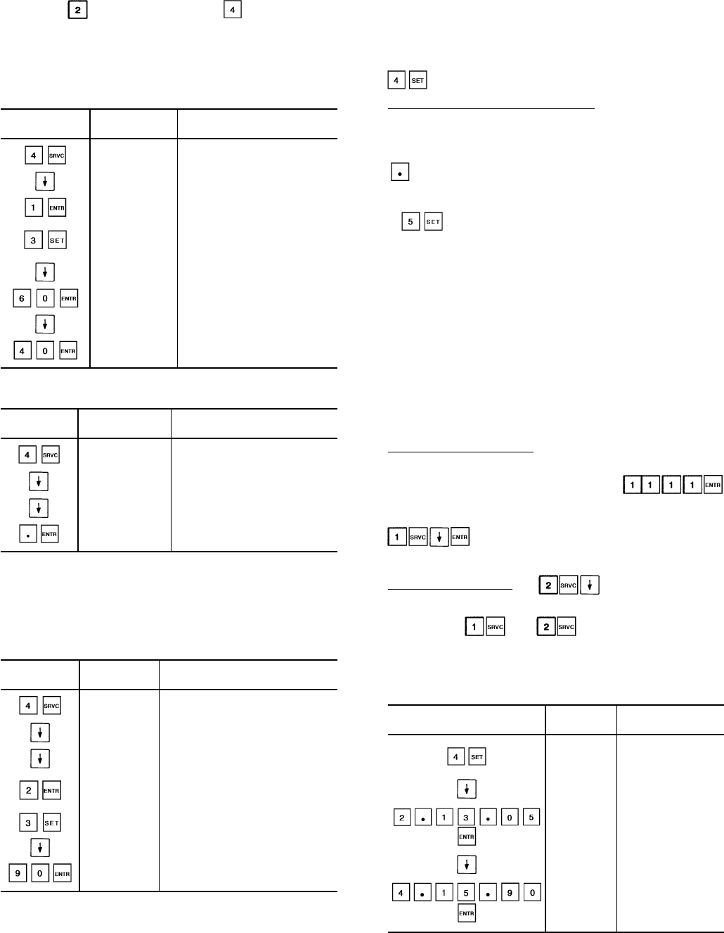
At field configuration step, select 4 to 20 mA loadshed
by entering (internally powered) or (externally pow-
ered) when the LSTYP 0 display appears. See Example 7B.
Then enter set points as follows. In this example, set points
are coordinates of the demand limit curve shown in Fig. 9.
Example 7A — Using Demand Limit
(First Log On as Shown in Table 12)
KEYPAD DISPLAY COMMENTS
ENTRY RESPONSE
FLD CFG Field configuration sub-
function of service function
LSTYP 0 Loadshed is not enabled
LSTYP 1 Loadshed is now enabled
for 2-stage switch control
DEMAND Demand Limit set points
subfunction of set point
function
DLS1 80 Loadshed 1 currently set
at 80%
DLS1 60 Loadshed reset to 60%
DLS2 50 Loadshed 2 currently set
at 50%
DLS2 40 Loadshed 2 reset to 40%
To Disable Demand Limit:
KEYPAD DISPLAY COMMENTS
ENTRY RESPONSE
FLD CFG Field configuration sub-
function of service function
ERTYP 0 Scroll past other elements
in the subfunction
LSTYP 1 Loadshed is enabled for
2-stage switch control
LSTYP 0 Loadshed is now disabled
NOTES:
1. Select 2 for internally powered 4 to 20 mA signal load limiting.
2. Select 3 for Carrier Comfort Network loadshed.
3. Select 4 for externally powered 4 to 20 mA signal load limiting.
Example 7B — Using Demand Limit (4-20 mA)
(First Log On As Shown in Table 12)
KEYPAD DISPLAY COMMENTS
ENTRY RESPONSE
FLD CFG Field configuration subfunction
of service function
ERTYP 0 Scroll past other elements in
the subfunction
LSTYP 0 Loadshed is not enabled
LSTYP 2 Loadshed is now enabled
for 4-20 mA internally-powered
signal control
DEMAND Demand Limit set points
DL20 100 Maximum demand limit is 100%
DL20 90 Maximum demand limit is 90%
Scrolling past the 4 to 20 mA demand limit set point brings
up the loadshed set points. The loadshed feature is activated
by a redline alert and loadshed commands from the CCN
loadshed option. The first set point is the group number, es-
tablished by the CCN system designer. The second option is
the loadshed demand delta, which defines the percent of the
load to be removed when a loadshed command is in effect.
The third set point is maximum loadshed time, which de-
fines the maximum length of time that a loadshed condition
is allowed to exist. The allowable range for this entry is zero
to 120 minutes.
Subfunction displays date, time, and day of the week.
Reading and Changing Time Display — Time is entered and
displayed in 24-hour time. The day of the week is entered as
a number.
1 = Mon, 2 = Tue, 7 = Sun, etc.
Key is used as the colon when entering time. See
Example 8.
subfunction accesses the leaving chiller fluid alert
limit (LMT) option. The value to be entered here is the num-
ber of degrees above the control set point at which an alert
should be generated. For example, if the control set point is
44 F, and an alert is desired (alert 70) if the fluid temperature
reaches 50 F, then enter 6 for this set point. The allowable
range for this entry is between 2 and 30 (F).
SERVICE FUNCTION — This function allows the techni-
cian to view and input configuration data. Factory configu-
ration data, field configuration data, and service configura-
tion data may be viewed or entered through the keypad and
display module. See Table 9 for a complete listing of con-
figurable items. Whenever a processor module is replaced in
the field, the complete list of configuration codes must be
entered.
Logging On/Logging Off — The service function is pass-
word protected. Therefore, to gain entry to this function,
this password must be entered. Pressing
allows the technician to view, change, or enter configuration
codes. To log off, perform the following keystrokes:
. The service function is once again password
protected.
Software Information — displays the version
number of the software that resides in the processor
module. The and subfunctions are summa-
rized in Table 12.
Example 8 — Setting Time of Day and
Day of Week
KEYPAD DISPLAY COMMENTS
ENTRY RESPONSE
TIME Time display sub-
function of set point
function
MON 16.00 Current setting is
Monday, 4:00 p.m.
TUE 13.05
New setting of
Tuesday, 1:05 p.m.
is entered
and displayed
JAN 01 90 Current date is
Jan. 1, 1990
APR 15 90
New setting
April 15, 1990
is entered
and displayed
43
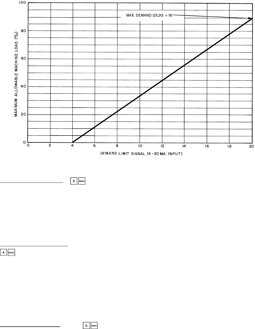
Factory Configuration Codes — allows entry into
the factory configuration subfunction. Under this subfunc-
tion, there are 7 groups of configuration codes that are down-
loaded at the factory. Each group is made up of 8 digits. If
processor module is replaced in the field, these 7 groups of
configuration codes must be entered through the keypad
and display module. Factory configuration codes (groups 1
through 7) that apply to the particular Flotronic™ II chiller
being serviced are found on a label diagram located inside
the control box cover. See Table 13 for a summary of factory
configuration subfunction keystrokes.
Adjustable Field Configurations — After logging on, press
to enter subfunction. The subfunction allows opera-
tion of the chiller to be customized to meet the particular
needs of the application. The chiller comes from the factory
preconfigured to meet the needs of most applications. Each
item should be checked to determine which configuration
alternative best meets the needs of a particular application.
See Table 14 for factory loaded configuration codes and al-
ternative configurations.
If processor module is replaced, the replacement module
is preloaded with factory default configuration codes. Each
configuration code must be checked and, if necessary, re-
configured to meet needs of the application. See Table 14 for
pre-loaded service replacement configuration codes.
Service Configuration Codes — Press to enter the
service configuration subfunction. The first 2 items under this
subfunction are 2 groups (8 digits each) of configuration codes
that are downloaded at the factory. If processor module is
replaced in the field, the 2 groups of configuration codes must
be entered through the keypad and display module. The
2 groups of configuration codes (groups 8 and 9) that apply
to the unit being serviced can be found on a label diagram
inside the control box cover. See Table 13 for keystroke in-
formation to enter configuration codes 8 and 9. The remain-
ing items in this subfunction are read-only data provided to
assist in service evaluations.
SCHEDULE FUNCTION — This function provides a means
to automatically switch chiller from an occupied mode to an
unoccupied mode. When using schedule function, chilled fluid
pump relay must be used to switch chilled fluid pump on
and off. Connections for chilled fluid pump relay are: TB3-3
and TB3-4. The chilled fluid pump relay starts chilled fluid
pump but compressors do not run until remote chilled fluid
pump interlock contacts are between TB6-1 and TB6-2 are
closed and leaving chilled fluid temperature is above set point.
If a remote chilled fluid pump interlock is not used, the first
compressor starts (upon a call for cooling) approximately
one minute after chilled fluid pump is turned on.
The unit can be programmed for inactive, single set point,
or dual set point operation.
When unit is configured for inactive, chilled fluid pump
relay remains energized continuously but is not used since
chiller is usually controlled by remote chilled fluid pump in-
terlock contacts.
When unit is configured for single set point operation, chilled
fluid pump relay is energized whenever chiller is in occu-
pied mode regardless of whether chiller is running. When
chiller is in unoccupied mode, chilled fluid pump relay is
not energized.
Fig. 9 — 4-20 mA Demand Limiting
44
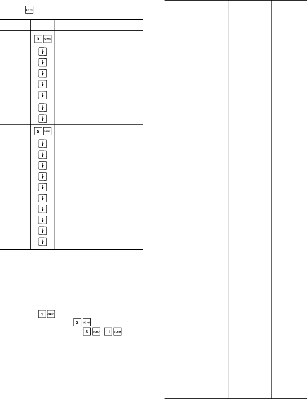
Table 13 — Factory Configuration Keystrokes
To change a configuration enter the new configuration
and press while on the correct configuration.
SUB- KEYPAD DISPLAY COMMENTS
FUNCTION ENTRY
3 FACTORY
CFG FACT CFG FACTORY
CONFIGURATION
CODES
XXXXXXXX Configuration
Code 1
XXXXXXXX Configuration
Code 2
XXXXXXXX Configuration
Code 3
XXXXXXXX Configuration
Code 4
XXXXXXXX Configuration
Code 5
XXXXXXXX Configuration
Code 6
XXXXXXXX Configuration
Code 7
5 SERVICE
CFG SRV CFG SERVICE
CONFIGURATION
CODES
XXXXXXXX Configuration
Code 8
XXXXXXXX Configuration
Code 9
REFRIG X Refrigerant Type
TDTYPE X Pressure Transducer Select
OPS X Oil Pressure Set Point
LPS X Low Pressure Set Point
FANTYP X Fan Staging Select
SH X EXV Superheat Set Point
MOP X EXV MOP Superheat
ZM X Z Multiplier
LEGEND
MOP — Maximum Operating Pressure
EXV — Electronic Expansion Valve
When unit is configured for dual set point, chilled liquid
pump relay is energized continuously, in both occupied and
unoccupied modes. Occupied mode places occupied chilled
water set point into effect; unoccupied mode places unoc-
cupied chilled water set point into effect.
Scheduling — is used to override any current sched-
ule in effect (for 0-4 hours). is used to activate a
clock for the scheduling function. - are used
to program schedules for specific occupied and unoccupied
periods.
The schedule consists of from one to 8 occupied time pe-
riods, set by the operator. These time periods can be flagged
to be in effect or not in effect on each day of the week. The
day begins at 00.00 and ends at 24.00. The machine is in
unoccupied mode unless a scheduled time period is in effect.
If an occupied period is to extend past midnight, it must be
programmed in the following manner: occupied period must
end at 24:00 hours (midnight); a new occupied period must
be programmed to begin at 00:00 hours.
Table 14 — Adjustable Field Configurations
FIELD CONFIGURATION
ITEM AND CODES
FACTORY SERVICE
CONFIGURATION REPLACEMENT
CODE CODE
CCN element address
(Entered by CCN Technician) 001 001
CCN Bus Number
(Entered by CCN Technician) 000 000
CCN Baud Rate
(Entered by CCN Technician) 9600 9600
Cooler Fluid Select
1 = Water (38 to 70 F
[3.3 to 21 C] Set Point)
2 = Medium Brine (15 to 70 F
[–9 to 21 C] Set Point)
1 = Standard Models
2 = Brine Models
1
Display Unit Select
0 = English
1 = Metric SI 00
Delay at Power Up 00
No. Circuit A Unloaders
0 = No Unloaders
1 = One Unloader
2 = Two Unloaders
0 = 30GN190-210*
1 = 30GN040-170* 0
No. Circuit B Unloaders
0 = No Unloaders
1 = One Unloader
2 = Two Unloaders
0 = 30GN040-070,
190-210*
1 = 30GN080-170* 0
Hot Gas Bypass Select
0 = No Valve 00
Loading Sequence Select
1 = Equal Circuit Loading
2 = Staged Circuit Loading 11
Lead/Lag Sequence Select
1 = Automatic
2 = Manual, Circuit A Leads
3 = Manual, Circuit B Leads
11
Oil Pressure Switch Select
0 = Not Used
1 = Air Cooled 00
Head Pressure Control Type
0 = Not Used
1 = Air Cooled 10
Head Pressure Control Method
1 = EXV Controlled
2 = Set Point Control for
Both Circuits
3 = Set Point Control for
Circuit A; EXV Control
for Circuit B
4 = Set Point Control for
Circuit B; EXV Control
for Circuit A
1
2 = 040,045
Brine Units 1
MotormasterTSelect
0 = None
2 = Indirect Control 00
Cooling Set Point
Control Select
0 = Single Set Point Control
1 = External Switch
Controlled Set Point
2 = Clock Controlled
Set Point
00
Cooling Reset Control Select
0 = No Reset
1 = 4-20 mA, Internally Powered
2 = External Temperature
Reset
3 = Return Fluid Reset
4 = 4-20 mA, Externally Powered
00
External Reset Sensor Select
0 = Thermistor Connected to
Options Module
1 = Obtained Through CCN
00
Outdoor-Air Sensor Select
0 = Not Selected
1 = Selected 00
Demand Limit Control Select
0 = No Demand Limiting
1 = Two External Switch Inputs
2 = Internal 4-20 mA Input
3 = CCN Loadshed
4 = External 4-20 mA Input
00
Ramp Load Select
(Pulldown Control)
0 = Disabled
1 = Enabled
10
Cooler Pump Interlock Select
0 = No Interlock
1 = With Interlock 10
Cooler Pump Control Select
0 = Not Controlled
1 = ON/OFF Controlled 10
Remote Alarm Option Select
0 = Not Selected
1 = Selected 00
Local/Enable-Stop-CCN
Switch Usage†
0 = Not Allowed
1 = Allowed
11
LEGEND
CCN — Carrier Comfort Network
EXV — Electronic Expansion Valve *And associated modular units.
†For reset of alarms.
45
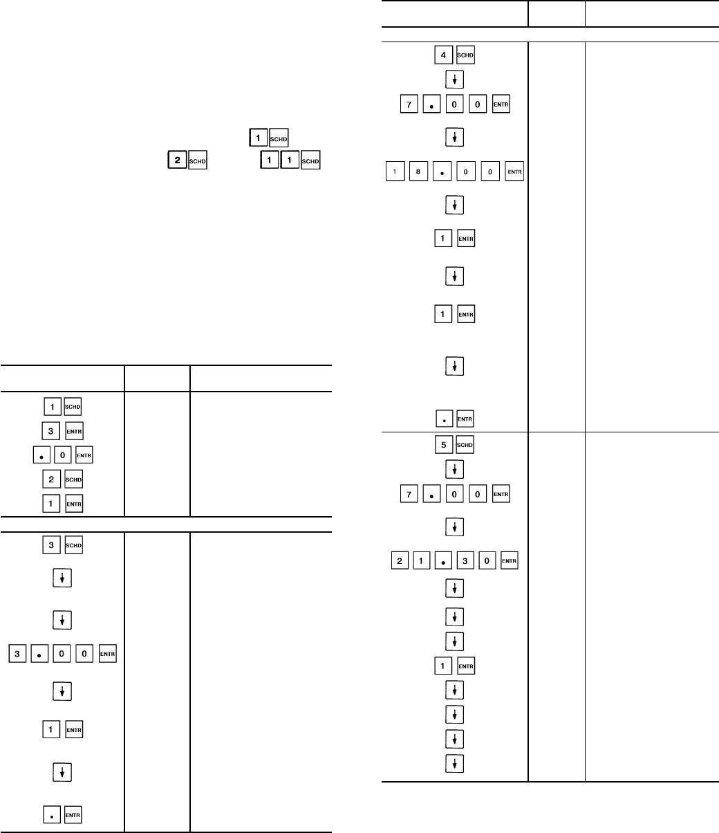
NOTE: This is true only if the occupied period starts at 00:00
(midnight). If the occupied period starts at a time other than
midnight, then the occupied period must end at 00:00 hours
(midnight) and new occupied period must be programmed
to start at 00:00 in order for the chiller to stay in the occu-
pied mode past midnight.
The time schedule can be overridden to keep unit in oc-
cupied mode for one, 2, 3, or 4 hours on a one-time basis.
See Example 9.
All subfunctions of schedule function are password
protected except the override subfunction, . Pass-
word entry into subfunctions through ,
is done through service function. See page 43, logging on/
logging off.
Figure 10 shows a schedule for an office building with the
chiller operating on a single set point schedule. The sched-
ule is based on building occupancy with a 3-hour off-peak
cool-down period from midnight to 3 a.m. following the week-
end shutdown. To learn how this sample schedule would be
programmed, see Example 9.
NOTE: This schedule was designed to illustrate the pro-
gramming of the schedule function and is not intended as a
recommended schedule for chiller operation.
Example 9 — Using the Schedule Function
KEYPAD DISPLAY COMMENT
ENTRY
OVRD 0 No scheduled override
in effect
OVRD 3 3 hours override in effect
OVRD 0 Override cancelled
CLOCK 0 Schedule function is inactive
CLOCK 1 Schedule function is enabled
through local unit clock
PROGRAMMING PERIOD 1:
PERIOD 1 Define schedule period 1.
Start of occupied time
OCC 00.00
For this example, first
period should start here
(at midnight) so no entry
is needed
UNO 00.00
Start of unoccupied time
(end of period). For this
example, period 1 should
end at 3:00 a.m.
UNO 3.00 Period 1 ends at 3:00 a.m.
MON NO
Monday is now flagged no
for period 1. To put period 1
into effect on Monday,
Monday must be flagged
yes
MON YES Monday is now flagged for
period 1 to be in effect
TUE YES
For this example, period 1
is to be in effect on Monday
only. All other days must be
checked to be sure that they
are flagged no. If any day is
flagged yes, change to no
TUE NO Tuesday is now flagged
no for period 1
Example 9 — Using the Schedule Function (cont)
KEYPAD DISPLAY COMMENT
ENTRY
PROGRAMMING PERIOD 2:
PERIOD 2 Define schedule period 2
OCC 00.00 Start of occupied time
OCC 7.00 Occupied time will start
at 7:00 a.m.
UNO 00.00
Start of unoccupied time
(end of period). For this
example, period 2 should
end at 18:00 (6:00 p.m.)
UNO 18.00 Period 2 ends at 18:00
(6:00 p.m.)
MON NO
Monday is now flagged no
for period 2. To put period 2
into effect on Monday,
Monday must be flagged yes
MON YES Monday is now flagged for
period 2 to be in effect
TUE NO
Tuesay is now flagged no
for period 2. To put period 2
into effect on Tuesday,
Tuesday must be flagged
yes
TUE YES Tuesday is now flagged for
period 2 to be in effect
WED YES
For this example, period 2
is to be in effect only on
Monday and Tuesday.
All other days must be
checked to be sure that
they are flagged no. If
a day is flagged yes,
change to no
WED NO Wednesday is now flagged
no for period 2
PERIOD 3 Define schedule
period 3
OCC 00.00 Start of occupied
time
OCC 7.00 Occupied time will start
at 7:00 a.m.
UNO 00.00
Start of unoccupied time
(end of period 3). For this
example, period 3 should
end at 21:30 (9:30 p.m.)
UNO 21.30 Period 3 ends at 21:30
(9:30 p.m.)
MON NO Check to be sure that
Monday and Tuesday are
flagged no for period 3
TUE NO
WED NO Wednesday is flagged
no, change to yes
WED YES Wednesday is now
flagged yes for period 3
THUR NO Check to be sure that all
other days are flagged no
FRI NO
SAT NO
SUN NO
CCN — Carrier Comfort Network
46
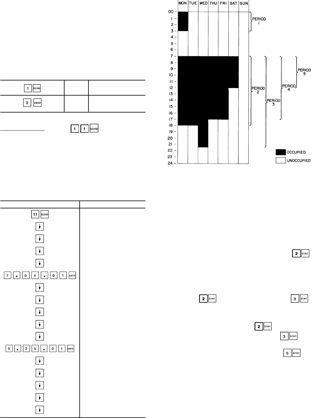
Periods 4 and 5 can be programmed in the same manner,
flagging Thursday and Friday yes for period 4 and Saturday
yes for period 5. For this example, periods 6, 7, and 8
are not used: they should be programmed OCC 00.00,
UNO 00.00.
NOTE: When a day is flagged yes for 2 overlapping periods,
occupied time will take precedence over unoccupied time.
Occupied times can overlap in the schedule with no
consequence.
To extend an occupied mode beyond its normal termina-
tion for a one-time schedule override, program as shown
below:
OVRD 0 Override is set for 0. Enter
the number of hours of
override desired
OVRD 3 Unit will now remain in
occupied mode for
an additional 3 hours
Holiday Schedule — Press to schedule up to
30 holiday periods. All holidays are entered with numerical
values. First, the month (01 to 12), then the day (01 to 31),
then the duration of the holiday period in days.
Examples: July 04 is 07.04.01.
Dec 25 - 26 is 12.25.02
If any of the 30 holiday periods are not used, the display
shows NEW.
See Example 10.
Example 10 — Holiday Schedule Function
ENTER DISPLAY
HOLIDAY
JAN01 02 (Includes Jan 1st
and 2nd)
APR17 01 (Includes April 17th)
MAY21 01(Includes May 21st)
JUL03 01 (Includes July 3rd)
JUL04 01 (Includes July 4th)
SEP07 01 (Includes Sep. 7th)
NOV26 02 (Includes Nov. 26th
and 27th)
DEC24 02 (Includes Dec. 24th
and 25th)
DEC30 02 (Includes Dec. 30th
and 31st)
NEW
MAY25 01 (Includes May 25th)
NEW
NEW
NEW
NEW
NEW (30TH HOLIDAY)
NEW indicates a holiday that has not been assigned yet.
TROUBLESHOOTING
The Flotronic™ II control has many features to aid the
technicians in troubleshooting a Flotronic II Chiller. By us-
ing the keypad and display module and the status function,
actual operating conditions of the chiller are displayed while
unit is running. Test function allows proper operation of com-
pressors, compressor unloaders, fans, EXVs and other com-
ponents to be checked while chiller is stopped. Service func-
tion displays how configurable items are configured. If an
operating fault is detected, an alarm is generated and an
alarm code(s) is displayed under the subfunction ,
along with an explanation of the fault. Up to 10 current alarm
codes are stored under this subfunction. For checking spe-
cific items, see Table 9.
Checking Display Codes — To determine how ma-
chine has been programmed to operate, check diagnostic
information ( ) and operating mode displays ( ).
If no display appears, follow procedures in Control Modules
section on page 63. If display is working, continue as
follows:
1. Note all alarm codes displayed, .
2. Note all operating mode codes displayed, .
3. Note leaving chilled water temperature set point in ef-
fect and current leaving water temperature, .
If machine is running, compare the ‘‘in effect’’ leaving
water temperature set point with current water tempera-
ture. Remember, if reset is in effect, the values may be
different because machine is operating to the modified chilled
water set point. If current temperature is equal to set point,
but set point is not the one desired, remember that if dual
set point has been selected in the schedule function, there
are 2 set points to which the machine can be operating.
Check the programming of schedule function to see if oc-
cupied or unoccupied set point should be in effect.
Fig. 10 — Sample Time Schedule
47
Unit Shutoff — To shut unit off, move LOCAL/ENABLE-
STOP-CCN switch to STOP position. Any refrigeration cir-
cuit operating at this time continues to complete the pum-
pout cycle. Lag compressors stop immediately, and lead
compressors run to complete pumpout.
Complete Unit Stoppage — Complete unit stoppage
can be caused by any of the following conditions:
1. Cooling load satisfied
2. Remote on/off contacts open
3. Programmed schedule
4. Emergency stop command from CCN
5. General power failure
6. Blown fuse in control power feed disconnect
7. Open control circuit fuse
8. LOCAL/ENABLE-STOP-CCN switch moved to STOP
position
9. Freeze protection trip
10. Low flow protection trip
11. Open contacts in chilled water flow switch (optional)
12. Open contacts in any auxiliary interlock. Terminals that
are jumpered from factory are in series with control switch.
Opening the circuit between these terminals places unit
in stop mode, similar to moving the control switch to
STOP position. Unit cannot start if these contacts are
open. If they open while unit is running, unit pumps down
and stops.
13. Cooler entering or leaving fluid thermistor failure
14. Low transducer supply voltage
15. Loss of communications between processor module and
other control modules
16. Low refrigerant pressure
17. Off-to-on delay is in effect.
Single Circuit Stoppage — Single circuit stoppage
can be caused by the following:
1. Low oil pressure in lead compressor
2. Open contacts in lead compressor high-pressure switch
3. Low refrigerant pressure
4. Thermistor failure
5. Transducer failure
6. Ground fault in lead compressor indicator (indicator is
field-supplied on 040-060, 070 [60 Hz], and 080-110 and
associated modular units)
7. High suction superheat
8. Low suction superheat
9. Lead compressor circuit breaker trip. Stoppage of one
circuit by a safety device action does not affect other
circuit. When a safety device trips on a lead compres-
sor, circuit is shut down immediately and EXV closes.
10. Ground fault for any circuit compressor (130-210 and
associated modular units).
Lag Compressor Stoppage — Lag compressor stop-
page can be caused by the following:
1. Open contacts in high-pressure switch
2. Compressor ground fault (indicator is field-supplied on
040-060, 070 [60 Hz], and 080-110 and associated modu-
lar units)
3. Compressor circuit breaker trip
4. Not required to run to meet cooling load requirement
If stoppage occurs more than once as a result of any of
the above safety devices, determine and correct the cause
before attempting another restart.
Restart Procedure — After cause for stoppage has been
corrected, restart is either automatic or manual, depending
on fault. Manual reset requires that LOCAL/ENABLE-
STOP-CCN switch be moved to STOP position, then back
to original operating position. Some typical fault conditions
are described in Table 15. For a complete list of fault con-
ditions, codes, and reset type, see Table 16.
Table 15 — Typical Stoppage Faults and Reset Types
Chilled Fluid, Low Flow Manual reset
Chilled Fluid, Low Temperature Auto reset first time, manual
if repeated in same day
Chilled Fluid Pump Interlock Manual reset
Control Circuit Fuse Blown Unit restarts automatically when
power is restored
High-Pressure Switch Open Manual reset
Low Refrigerant Pressure Auto reset first time, then
manual if within same day
Low Oil Pressure Manual reset
Discharge Gas Thermostat Open Manual reset
POWER FAILURE EXTERNAL TO THE UNIT — Unit
restarts automatically when power is restored.
Alarms and Alerts — These are warnings of abnormal
or fault conditions, and may cause either one circuit or the
whole unit to shut down. They are assigned code numbers as
described below. These code numbers are displayed
on the HSIO when the subfunction is entered. A
fault that affects one one circuit of the chiller will generate
an alert, and a fault that affects the entire unit will generate
an alarm.
Following is a detailed description of each alarm and alert
code error and possible cause. Manual reset is accomplished
by moving LOCAL/ENABLE-STOP-CCN Switch to STOP
position, then back to LOCAL or CCN position. See
Table 16 for listing of each alarm and alert code.
Code 0 No alarms or alerts exist
Codes1-8 Compressor failure
If DSIO-LV or -EXV relay module control relay feedback
switch or signal is sensed as open during operation of a com-
pressor, microprocessor detects this and stops compressor,
energizes alert light, and displays a code of 1, 2, 3, 4, 5, 6,
7, or 8 depending on the compressor. Compressor locks off;
to reset, use manual reset method.
If lead compressor in a circuit shuts down, the other com-
pressors in the circuit stop and lock off. Only the alert mode
for lead compressor is displayed.
The microprocessor is also programmed to indicate com-
pressor failure if feedback terminal on DSIO-LV or -EXV J3
terminal strip receives voltage when compressor is not sup-
posed to be on.
NOTE: It takes 5 seconds for the control to generate the alarm
code and lock out the compressor(s) on compressor failure
code(s) 1 through 8.
48

Table 16 — Alarm and Alert Codes
DISPLAY ALARM DESCRIPTION ACTION TAKEN CIRCUIT RESET PROBABLE CAUSEOR
ALERT BY CONTROL PUMPDOWN METHOD
0— No Alarms or Alerts Exist — — — —
1
Alert
Compressor A1 failure Circuit A shut down No Manual High-pressure switch trip, or wiring
error.
2, 3, 4 Compressor A2, A3, A4 failure Compressor shut down Yes Manual CPCS Ground Fault Protection
5Compressor B1 failure Circuit B shut down No Manual
6, 7, 8 Compressor B2, B3, B4 failure Compressor shut down Yes Manual
9Alarm Leaving fluid thermistor failure Unit shut down Yes Auto.
Thermistor or transducer failure
or wiring error.
10 Entering fluid thermistor failure Unit shut down Yes Auto.
19
Alert
Compressor A1 sensor failure Circuit A shut down Yes Auto.
20 Compressor B1 sensor failure Circuit B shut down Yes Auto.
21 Reset thermistor failure Normal set point used No Auto.
22
Alert
Discharge pressure transducer failure, circuit A Circuit A shut down Yes Auto.
Transducer failure or wiring error.
23 Discharge pressure transducer failure, circuit B Circuit B shut down Yes Auto.
24 Suction pressure transducer failure, circuit A Circuit A shut down No Auto.
25 Suction pressure transducer failure, circuit B Circuit B shut down No Auto.
26 Oil pressure transducer failure, circuit A Circuit A shut down No Auto.
27 Oil pressure transducer failure, circuit B Circuit B shut down No Auto.
28 Alarm Transducer supply voltage low Unit shut down No Auto. Unit voltage low or PS1 faulty.
29 LOCAL/ENABLE-STOP-CCN Unit shut down No Manual Switch failure or wiring error.
30 Alert 4-20 mA reset input failure Normal set point used No Auto.
31 4-20 mA demand limit failure Demand limit ignored No Auto.
32
Alarm
Loss of communication with DSIO-LV Unit shut down No Auto. Wiring error or faulty module
or improper address code.
33 Loss of communication with DSIO-EXV Unit shut down No Auto.
34 Loss of communication with 4 In/4 Out module Unit shut down Yes Auto.
35 — Not used — — — —
36
Alert
Low refrigerant pressure circuit A Circuit A shut down No * Low refrigerant charge, plugged filter
drier, faulty expansion valve.
37 Low refrigerant pressure circuit B Circuit B shut down No * Low refrigerant charge, plugged filter
drier, faulty expansion valve.
38
Alert
Failure to pump out circuit A Circuit A shut down No Manual Faulty expansion valve, transducer,
or thermistor.
39 Failure to pump out circuit B Circuit B shut down No Manual Faulty expansion valve, transducer,
or thermistor.
40
Alert
Low oil pressure circuit A Circuit A shut down No Manual Low oil level, circuit breaker trip,
faulty expansion valve, crankcase
heater, or pressure transducer.
41 Low oil pressure circuit B Circuit B shut down No Manual Low oil level, circuit breaker trip,
faulty expansion valve, crankcase
heater, or pressure transducer.
42 Alarm Cooler freeze protection Unit shut down No * Low fluid flow or faulty thermistor.
43 Low cooler fluid flow Unit shut down No Manual Chilled fluid pump failure
or faulty thermistor.
44
Alert
Low suction temperature circuit A Circuit A shut down
after 10 minutes No Manual Faulty expansion valve or thermistor.
45 Low suction temperature circuit B Circuit B shut down
after 10 minutes No Manual Faulty expansion valve or thermistor.
46
Alert
High suction superheat circuit A Circuit A shut down Yes Manual Low charge, faulty expansion valve or
thermistor, or plugged filter drier.
47 High suction superheat circuit B Circuit B shut down Yes Manual Low charge, faulty expansion valve or
thermistor, or plugged filter drier.
48 Alert Low suction superheat circuit A Circuit A shut down Yes Manual Faulty EXV or thermistor.
49 Low suction superheat circuit B Circuit B shut down Yes Manual Faulty EXV or thermistor.
50
Alarm
Illegal configuration Unit cannot start — Manual Configuration error.
51 Initial configuration required Unit cannot start — Manual Configuration omitted.
52 Emergency stop by CCN command Unit shut down Yes CCN Network command.
53
Alarm
Cooler pump interlock failure Unit shut down No Manual Failure of cooler pump or controls
54 Cooler pump interlock failure Unit shut down No Manual Failure of cooler pump or controls
55 Cooler pump interlock failure Cooler pump shut down — Manual Failure of cooler pump relay or interlock
56 Alert WSM communication failure WSM forces removed — Auto. Wiring fault or module failure
57
Alert
Calibration required for discharge pressure
transducer, circuit A Circuit cannot start — Auto.
Transducer not calibrated
58 Calibration required for discharge pressure
transducer, circuit B Circuit cannot start — Auto.
59 Calibration required for suction pressure
transducer, circuit A Circuit cannot start — Auto.
60 Calibration required for suction pressure
transducer, circuit B Circuit cannot start — Auto.
61 Calibration required for oil pressure
transducer, circuit A Circuit cannot start — Auto.
62 Calibration required for oil pressure
transducer, circuit B Circuit cannot start — Auto.
49
Table 16 — Alarm and Alert Codes (cont)
DISPLAY ALARM DESCRIPTION ACTION TAKEN CIRCUIT RESET PROBABLE CAUSEOR
ALERT BY CONTROL PUMPDOWN METHOD
63 Alarm Complete unit shutdown Alarm only — Auto. Check individual alarms
64 Alert Loss of charge, circuit A Circuit cannot start — Auto. Refrigerant leak or transducer
failure65 Loss of charge, circuit B Circuit cannot start — Auto.
66 Alarm FSM communication loss FSM forces removed — Auto. Wiring faulty or module failure
67 Alarm Transducer calibration date code failure Unit cannot start — Auto. Incorrect date code entered
68,69 — Not used — — — —
70 Alert High leaving chilled fluid temperature Alarm only — Auto. Building load greater than unit capacity,
low water/brine flow, or compressor
fault. Check for other alarms or alerts.
LEGEND
CPCS — Compressor Protection Control Module
FSM — Flotronic™ System Manager
PS — Power Supply
WSM — Water System Manager
*Reset automatic first time, manual if repeated same day.
Possible causes of failure:
1. High-Pressure Switch Open — High-pressure switch for
each compressor is wired in series with 24-v power that
energizes compressor control relay. If high-pressure switch
opens during operation, compressor stops. This is
detected by microprocessor through the feedback
terminals.
2. DSIO-LV or DSIO-EXV Module Failure — If a DSIO-LV
relay module relay fails open or closed, microprocessor
detects this, locks compressor off, and indicates an
error.
3. Wiring Errors — If a wiring error exists causing CPCS,
CR, or feedback switch to not function properly, micro-
processor indicates an error.
4. Processor (PSIO) Failure — If hardware that monitors
feedback switch fails, or processor fails to energize relay
module relay to on, an error may be indicated.
NOTE: The control does not detect circuit breaker fail-
ures. If a circuit breaker trips on lead compressor in a
circuit, a low oil pressure failure is indicated. On the other
compressors, no failure is indicated.
5. Ground Fault Module on 130-210 and associated modu-
lar units (CGFA or CGFB) Open — Module contacts are
in lead compressor circuits, but ground fault could be in
any compressor in affected circuit.
Ground fault of any 040-110 and associated modular unit
compressor (field-supplied accessory on 040-060 and 070,
60 Hz units; standard on 070, 50 Hz and 80-110 and as-
sociated modular units) will cause a trip.
6. Checkout Procedure — Shut off main power to unit. Turn
on control power, then step through subfunc-
tion to proper compressor number (i.e., failure
code 5 is compressor B1). Next, energize the step. If step
works correctly, then failure code is caused by:
• HPS (high-pressure switch) open
• Misplaced feedback wire from J4 and J5 terminals
• Ground wire and 24-v feeds reversed on one or more
points on J3
Compressor Alarm/Alert Circuit — For compres-
sor A1 circuit, processor closes contacts between J4 termi-
nals 2 and 3 to start compressor. See Fig. 11A-11C. Safeties
shown to left of J4 must be closed in order for power to
reach compressor control relay, and the feedback input ter-
minals on J3.
Failure of power to terminal 1 on J3, when contacts be-
tween 2 and 3 on J4 should be closed, causes a code 1 alert.
Terminal 2 on J3 is the other leg of the compressor A1
feedback channel. It is connected to the 24-v common.
NOTE: Similar connections for each compressor can be fol-
lowed on the unit wiring diagrams located on the unit.
Code 9 Leaving fluid thermistor failure (alarm)
Code 10 Entering fluid thermistor failure (alarm)
If temperature measured by these thermistors is outside
range of –40 to 240 F (–40 to 116 C), unit shuts down after
going through a normal pumpout. Reset is automatic if tem-
perature returns to the acceptable range, and unit start-up fol-
lows normal sequence. The cause of the fault is usually a
bad thermistor, wiring error, or loose connection.
Code 19 Compressor A1 suction sensor failure (alert)
Code 20 Compressor B1 suction sensor failure (alert)
On units with thermistors, if temperature measured by these
thermistors is outside the range of –40 to 240 F (–40 to
116 C), affected circuit shuts down after going through a nor-
mal pumpout. Other circuit continues to run. Reset is auto-
matic if temperature returns to the acceptable range, and cir-
cuit start-up follows normal sequence. The cause of this fault
is usually a bad thermistor, wiring error, or loose
connection.
On units with transducers, if the saturated suction tem-
perature is greater than the leaving fluid temperature plus
10° F (5.5 C) for more than 5 minutes, the affected circuit
shuts down (after going through normal pumpout). The reset
is automatic if the saturated suction temperature returns to
the acceptable range and start-up follows the normal se-
quence. The cause of this fault is usually a bad transducer,
a wiring error, or a loose connection.
50
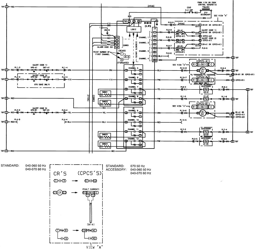
Code 21 Reset thermistor failure (applies only to installa-
tions having external temperature reset) (alert)
If temperature measured by this thermistor is outside range
of –40 to 240 F (–40 to 116 C), reset function is disabled and
unit controls to normal set point. If temperature returns to
the acceptable range, reset function is automatically en-
abled. The cause of this fault is usually a bad thermistor,
wiring error, or loose connection.
Code 22 Compressor A1 discharge pressure
transducer failure (alert)
Code 23 Compressor B1 discharge pressure
transducer failure (alert)
Code 24 Compressor A1 suction pressure transducer
failure (alert)
Code 25 Compressor B1 suction pressure transducer
failure (alert)
Code 26 Compressor A1 oil pressure transducer failure (alert)
Code 27 Compressor B1 oil pressure transducer failure (alert)
If output voltage of any of these transducers is greater than
5 v, affected circuit shuts down without going through pum-
pout process (Alerts 24-27). Other circuit continues to run.
Reset is automatic if output voltage returns to the acceptable
range, and circuit start-up follows normal sequence. The cause
of this fault is usually a bad transducer or a wiring error.
Code 28 Low transducer supply voltage (alarm)
If transducer supply voltage is less than 4.5 v or greater
than 5.5 v, unit shuts down without going through pumpout
process. Reset is automatic if supply voltage returns to the
acceptable range, and circuit start-up follows normal se-
quence. The cause of this fault is usually a faulty trans-
former or primary voltage is out of range.
LEGEND
C—Contactor
CB — Circuit Breaker
COM, COMM — Communications Bus
CPCS — Compressor Protection
Control Module
CR — Compressor Contactor Relay
DGT — Discharge Gas Thermostat (Optional)
DSIO — Relay Module (Low Voltage)
HPS — High-Pressure Switch
LV — Low Voltage
NC — Normally Closed
NO — Normally Open
PL — Plug
PWR — Power
SNB — Snubber
TB — Terminal Block
TRAN — Transformer
U—Unloader
Fig. 11A — 24-V Safety Circuit Wiring (040-070)
51
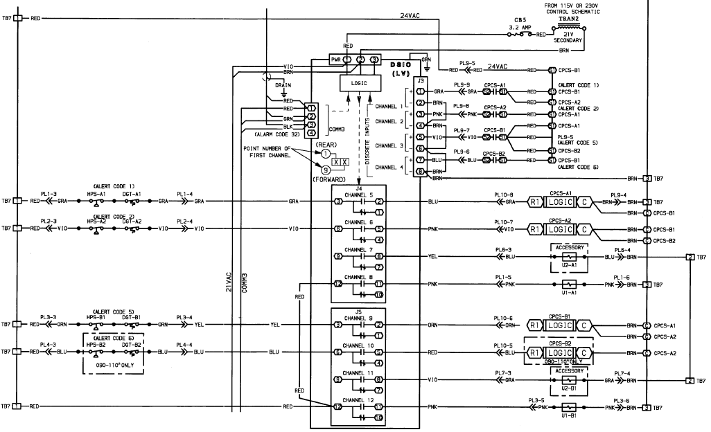
The voltage supplied to the processor is polarized. When
checking for proper voltage supply, be sure to consider this
polarity. If voltage appears to be within acceptable toler-
ance, check to be sure the transformer supplying PS1 is not
grounded. Grounding the supply transformer can result in
serious damage to the control system.
Code 29 LOCAL/ENABLE-STOP-CCN Switch Failure
(switch resistances out of range) (alarm)
This fault occurs due to the failure of the switch or due to
a wiring error.
Code 30 Reset input failure (4 to 20 mA) (alert)
Code 31 Demand limit input failure (4 to 20 mA) (alert)
These codes apply only if unit is configured for these func-
tions. If 4 to 20 mA signal is less than 4 or more than
20 mA, reset or demand limit function is disabled and unit
functions normally. If mA signal returns to the acceptable
range, function is automatically enabled.
Code 32 Loss of communication with compressor
relay module (DISO-LV) (alarm)
Code 33 Loss of communication with EXV relay
module (DSIO-EXV) (alarm)
If communication is lost with either of these modules, unit
shuts down without pumpout. This alarm resets automati-
cally when communication is restored. The unit starts up nor-
mally after alarm condition is reset. Probable cause of con-
dition is a faulty or improperly connected plug, wiring error,
or faulty module.
Loss of communication can be attributed to a grounded
transformer with a secondary voltage of 21 vac supplying
the PSIO, DSIO-LV, or 4 IN/4 OUT modules; the 12.5-vac
transformer supplying the DSIO-EXV module; or the
24-vac transformer supplying PS1 for the transformers.These
transformers should not be grounded, or serious damage to
controls can result. Check to be sure the transformers are
not grounded.
NOTE: If a blank PSIO module is downloaded without be-
ing connected to the modules DSIO, this alarm is
energized.
Code 34 Loss of communication with 4 In/4 Out module
(alarm)
This applies only if one or more of the following options
are used:
• external temperature reset
• 4 to 20 mA temperature reset
• external switch controlled dual set point
• switch controlled demand limit
• 4 to 20 mA demand limit
• hot gas bypass
If communication is lost with 4 IN/4 OUT module, the
unit shuts off automatically, after finishing pumpout. Reset
of alarm is automatic when communication is restored. Start-up
after alarm is remedied follows a normal sequence. Probable
cause of condition is a faulty or improperly connected plug,
wiring error, or faulty module.
LEGEND
C—Contactor
CB — Circuit Breaker
COMM — Communications Bus
CPCS — Compressor Protection Control Module
DGT — Discharge Gas Thermostat (Optional)
DSIO — Relay Module (Low Voltage)
HPS — High-Pressure Switch
LV — Low Voltage
PL — Plug
PWR — Power
TB — Terminal Block
TRAN — Transformer
U—Unloader
*And associated modular units.
Fig. 11B — 24-V Safety Circuit Wiring (080-110 and Associated Modular Units)
52
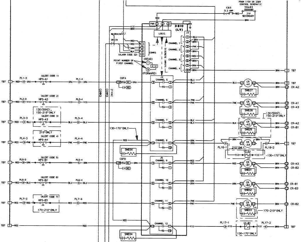
Loss of communication can be attributed to a grounded
transformer with a secondary voltage of 21 vac supplying
the PSIO, DSIO-LV, or 4 IN/4 OUT; the 12.5-vac trans-
former supplying the DSIO-EXV module, or the 24-vac trans-
former supplying PS1 for the transformers.These transformers
should not be grounded, or serious damage to controls can
result. Check to be sure the transformers are not grounded.
Code 36 Low refrigerant pressure, Circuit A (alert)
Code 37 Low refrigerant pressure, Circuit B (alert)
If suction pressure transducer senses a pressure below set
point for more than 5 minutes at start-up or more than
2 minutes during normal operation, affected circuit shuts down
without going through the pumpout process. Reset is auto-
matic when pressure reaches 10 psig above set point if there
have been no previous occurrences of this fault on the same
day. If this is a repeat occurrence on same day, then reset is
manual, with LOCAL/ENABLE-STOP-CCN switch. Fac-
tory configured set point is 27 psig for standard chillers and
12 psig for brine chillers.
Possible causes of fault are low refrigerant charge, faulty
EXV, plugged filter drier, or faulty transducer.
Code 38 Failure to pump out, Circuit A (alert)
Code 39 Failure to pump out, Circuit B (alert)
The pumpout process is terminated when saturated suc-
tion temperature is 10° F (5.6° C) below temperature at be-
ginning of pumpout, or 10° F (5.6° C) below leaving water
temperature or reaches a saturated suction temperature of
–15 F (–26 C). If appropriate saturated suction temperature
is not met within 3 minutes (on 2 consecutive tries), circuit
shuts down without pumpout. Reset is manual with LOCAL/
ENABLE-STOP-CCN switch, and start-up follows normal
sequence.
Possible causes for this alarm are a bad thermistor or trans-
ducer or a faulty expansion valve.
Code 40 Low oil pressure, Circuit A (alert)
Code 41 Low oil pressure, Circuit B (alert)
LEGEND
CB — Circuit Breaker
CGF — Ground Fault Module
COMM — Communications Bus
CR — Compressor Contactor Relay
DSIO — Relay Module (Low Voltage)
HPS — High-Pressure Switch
LV — Low Voltage
PL — Plug
SNB — Snubber
TB — Terminal Block
TRAN — Transformer
U—Unloader
*And associated modular units.
Fig. 11C — 24-V Safety Circuit Wiring (130-210 and Associated Modular Units)
53
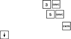
If oil pressure differential is less than set point for more
than 2 minutes at start-up, or more than one minute during
normal operation, affected circuit shuts down without going
through pumpout process. Reset is manual with LOCAL/
ENABLE-STOP-CCN switch, and start-up follows normal
sequence. Factory configured differential oil pressure is
6 psig.
Possible causes of fault are faulty compressor, expansion
valve, crankcase heater or transducer, refrigerant over-
charge, insufficient oil charge, or tripped circuit breaker.
Code 42 Cooler freeze protection (alarm)
If cooler entering or leaving water temperature is below
34° F (1.1° C) for water or more than 8° F (4.4° C) below
set point for brine, unit shuts down without pumpout. Chilled
water pump continues to run if controlled by chiller con-
trols. Reset is automatic when leaving fluid temperature reaches
6° F (3° C) above set point, providing there has been no prior
occurrence of this fault the same day. If fault has occurred
previously the same day, reset is manual with LOCAL/
ENABLE-STOP-CCN switch.
Possible causes of fault are low fluid flow or faulty
thermistor.
Code 43 Low fluid flow (alarm)
If any compressors are operating and entering fluid tem-
perature is 3° F (1.7° C) or more below leaving fluid tem-
perature for more than one minute, unit shuts down without
pumpout. Chilled fluid pump also shuts down. Reset is manual
with LOCAL/ENABLE-STOP-CCN switch, and start-up fol-
lows normal sequence.
This is a suitable method for sensing low fluid flow be-
cause entering fluid thermistor is in the cooler shell and re-
sponds more quickly to compressor operation than the leav-
ing fluid thermistor in the leaving water nozzle. Possible causes
of fault are faulty chilled fluid pump, control or thermistor.
Code 44 Low cooler suction temperature, Circuit A (alert)
Code 45 Low cooler suction temperature, Circuit B (alert)
If saturated suction temperature is less than 32 F (0°C)
and is 20° F (11° C) for water or 30° F (16° C) for brine or
more below leaving fluid temperature, mode 14 is dis-
played. Unit continues to run, but additional compressors are
not allowed to start. If condition persists for more than
10 minutes, fault code is displayed, and unit shuts down with-
out pumpout. Reset is manual with LOCAL/ENABLE-STOP-
CCN switch, and start-up follows normal sequence.
Possible causes of fault are low refrigerant charge, plugged
filter drier, or a faulty expansion valve or thermistor.
Code 46 High suction superheat, Circuit A (alert)
Code 47 High suction superheat, Circuit B (alert)
If expansion valve is fully open, suction superheat is greater
than 75 F (42 C), and saturated evaporator temperature is
less than MOP (maximum operating pressure) for more than
5 minutes, unit shuts down after normal pumpout process.
Reset is manual with LOCAL/ENABLE-STOP-CCN switch,
and start-up follows normal sequence.
Possible causes of fault are low refrigerant charge, plugged
filter drier, or a faulty expansion valve or thermistor.
Code 48 Low suction superheat, Circuit A (alert)
Code 49 Low suction superheat, Circuit B (alert)
If EXV is at minimum position, suction superheat is less
than 10° F (5.5° C) or saturated evaporator temperature is
greater than MOP (maximum operating pressure) for more
than 5 minutes, affected circuit shuts down after going through
pumpout process. Reset is manual with LOCAL/ENABLE-
STOP-CCN switch, and start-up follows normal sequence.
Possible causes of fault are faulty expansion valve or
thermistor.
Code 50 Illegal configuration (alarm)
This fault indicates a configuration error. Unit is not al-
lowed to start. Check all configuration data and set points
and correct any errors.
Code 51 Initial configuration required (alarm)
This fault indicates factory configuration has not been done,
and unit is not allowed to start. Refer to unit wiring
label diagrams for factory configuration codes. There are
9 groups of 8-digit numbers that must be entered. The first
7 groups must be entered under subfunction. Groups
8 and 9 must be entered under subfunction.
Enter each group, then press the key. Press the
down arrow after each group to bring up the next
empty screen. Unit should start after factory and field con-
figurations are correctly entered.
The usual cause of this fault is replacement of the pro-
cessor module. Refer to instructions accompanying the re-
placement module.
Code 52 Emergency stop by CCN command (alarm).
Unit shuts down immediately without pumpout when this
command is received, and goes through normal start-up when
command is cancelled.
Code 53 Cooler pump interlock failure — Contacts fail to
close at start-up (alarm)
If the unit is configured for cooler pump control and cooler
pump interlock, and the interlock fails to close within one
minute of starting the cooler pump, the unit is shut down
without pumpout. The cooler pump is also shut down. Reset
is manual with the LOCAL/ENABLE-STOP-CCN switch,
and start-up follows the normal sequence.
Possible causes are:
1. Interlock switch fails to close within one minute after chilled
water pump starts
2. Interlock switch opens during unit operation
3. Interlock voltage is detected, but unit is not configured
for interlock
4. Interlock voltage is outside its valid range
If any of these conditions occur, all compressors are dis-
abled and, if running, shutdown occurs without pumpout.
Chilled fluid pump also shuts down. Reset is manual, with
LOCAL/ENABLE-STOP-CCN switch. Most probable cause
of this fault is shutdown or failure of chilled fluid pump to
start. Other possibilities are improper configuration or wir-
ing errors.
Code 54 Cooler pump interlock failure — Contacts open
during normal operation (alarm)
If the unit is configured for cooler pump control and cooler
pump interlock, and the interlock opens during normal op-
eration, the unit is shut down without pumpout. The cooler
pump is also shut down. Reset is manual with the LOCAL/
ENABLE-STOP-CCN switch, and startup follows the nor-
mal sequence.
Possible causes are:
1. Interlock switch fails to close within one minute after chilled
water pump starts
2. Interlock switch opens during unit operation
3. Interlock voltage is detected, but unit is not configured
for interlock
4. Interlock voltage is outside its valid range
If any of these conditions occur, all compressors are dis-
abled and, if running, shutdown occurs without pumpout.
Chilled fluid pump also shuts down. Reset is manual, with
54
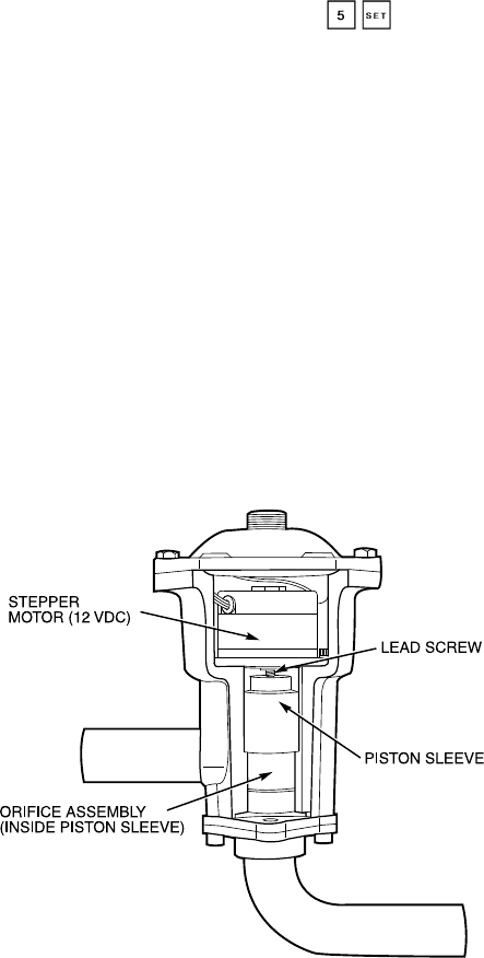
LOCAL/ENABLE-STOP-CCN switch. Most probable cause
of this fault is shutdown or failure of chilled fluid pump to
start. Other possibilities are improper configuration or wir-
ing errors.
Code 55 Cooler pump interlock failure — Contacts closed
when pump is off (alarm)
If the unit is configured for cooler pump control and cooler
pump interlock, and the interlock is closed when the cooler
pump relay is off, the cooler pump shall be shut down and
the unit prevented from starting. Reset is manual with the
LOCAL/ENABLE-STOP-CCN switch.
Possible causes are:
1. Interlock switch fails to close within one minute after chilled
water pump starts
2. Interlock switch opens during unit operation
3. Interlock voltage is detected, but unit is not configured
for interlock
4. Interlock voltage is outside its valid range
If any of these conditions occur, all compressors are dis-
abled and, if running, shutdown occurs without pumpout.
Chilled fluid pump also shuts down. Reset is manual, with
LOCAL/ENABLE-STOP-CCN switch. Most probable cause
of this fault is shutdown or failure of chilled fluid pump to
start. Other possibilities are improper configuration or wir-
ing errors.
Code 56 Water System Manager (WSM) communication
failure (alert)
If the WSM has previously established communications
with the control and the WSM is not disabled and has not
communicated with the control within the last 5 minutes, the
control will remove all WSM forces from the chillers vari-
ables. The chiller will continue to operate on a stand-alone
basis. Reset is automatic when the WSM re-establishes com-
munication with the unit.
Code 57 Calibration required for discharge pressure trans-
ducer, circuit A (alert)
Code 58 Calibration required for discharge pressure trans-
ducer, circuit B (alert)
If the discharge pressure transducer has not been success-
fully calibrated, the circuit will not start. Reset is automatic
upon successful calibration of the transducer.
Code 59 Calibration required for suction pressure trans-
ducer, circuit A (alert)
Code 60 Calibration required for suction pressure trans-
ducer, circuit B (alert
If the suction pressure transducer has not been success-
fully calibrated, the circuit will not start. Reset is automatic
upon successful calibration of the transducer.
Code 61 Calibration required for oil pressure transducer,
circuit A (alert)
Code 62 Calibration required for oil pressure transducer,
circuit B (alert)
If the oil pressure transducer has not been successfully
calibrated, the circuit will not start. Reset is automatic upon
successful calibration of the transducer.
Code 63 Complete unit shutdown due to failure (alarm)
This alarm alerts the user that the unit is totally shut down
due to one or more fault conditions. Reset is automatic when
all alarms causing complete unit shutdown are reset.
Code 64 Loss of charge, circuit A (alert)
Code 65 Loss of charge, circuit B (alert)
If the unit uses suction and discharge transducers with the
same part number, and the discharge pressure is below
10 psig when the unit is shut down, the circuit will not start.
Reset is automatic when the discharge pressure rises above
15 psig. This alarm does not function in units using different
part number transducers for suction and discharge pressure,
since the discharge transducer in that application does not
function below 20 psig.
Code 66 Flotronic™ System Manager loss of communi-
cations (alarm)
If the FSM has established communication with the con-
trol, and the communication is subsequently lost for more
than 20 seconds, the control will remove all forces on the
chiller variables. Control of the unit will revert to stand-
alone basis, and reset is automatic upon re-establishment of
communication.
Code 67 Transducer calibration failure due to incorrect date
code (alarm)
This applies to units having pressure transducers with the
same part number for both suction and discharge pressures.
If the transducer calibration is attempted and the factory de-
fault date code (Jan. 1, 1980) is in the date variable, then the
unit will not start. Reset is automatic when the proper date
code is entered upon calibration.
Code 70 High leaving chilled fluid temperature (alert)
If the leaving chilled fluid temperature is rising and is
higher than the limit established in the subfunction
and the unit is at full capacity then alert 70 will be activated.
The unit will continue to function normally, and reset will
be automatic upon leaving chilled fluid temperature drop-
ping to 5° F below the limit or less than control
set point.
Electronic Expansion Valve (EXV)
NOTE: This applies to all units except 30GN040 and 045
with optional brine. The 040 and 045 units with optional brine
have TXVs.
EXV OPERATION — These valves control the flow of liq-
uid refrigerant into the cooler. They are operated by the pro-
cessor to maintain a specified superheat at lead compressor
entering gas thermistor (located between compressor motor
and cylinders). There is one EXV per circuit. See
Fig. 12.
High-pressure liquid refrigerant enters valve through bot-
tom. A series of calibrated slots are located in side of orifice
assembly.As refrigerant passes through orifice, pressure drops
and refrigerant changes to a 2-phase condition (liquid and
Fig. 12 — Electronic Expansion Valve (EXV)
55
vapor). To control refrigerant flow for different operating con-
ditions, sleeve moves up and down over orifice, thereby chang-
ing orifice size. Sleeve is moved by a linear stepper motor.
Stepper motor moves in increments and is controlled di-
rectly by the processor module. As stepper motor rotates,
motion is transferred into linear movement by lead screw.
Through stepper motor and lead screws, 1500 discrete steps
of motion are obtained. The large number of steps and long
stroke result in very accurate control of refrigerant flow.
The subfunction shows EXV valve position as
a percent of full open. Position should change constantly while
unit operates. If a valve stops moving for any reason (me-
chanical or electrical) other than a processor or thermistor
failure, the processor continues to attempt to open or close
the valve to correct the superheat. Once the calculated valve
position reaches 120 (fully closed) or 1500 (fully open), it
remains there. If EXV position reading remains at 120 or
1500, and the thermistors and pressure transducers are read-
ing correctly, the EXV is not moving. Follow EXV checkout
procedure below to determine cause.
The EXV is also used to limit cooler suction temperature
to 50 F (10 C). This makes it possible for chiller to start at
higher cooler fluid temperatures without overloading com-
pressor. This is commonly referred to as MOP (maximum
operating pressure), and serves as a load limiting device to
prevent compressor motor overloading. This MOP or load
limiting feature enables the 30G Flotronic™ II chillers to
operate with up to 95 F (35 C) entering fluid temperatures
during start-up and subsequent pull-down.
CHECKOUT PROCEDURE — Follow steps below to di-
agnose and correct EXV problems.
1. Check EXV driver outputs. Check EXV output signals at
appropriate terminals on EXV driver module (see
Fig. 13) as follows:
Connect positive test lead to terminal 1 on EXV driver.
Set meter for approximately 20 vdc. Enter outputs
subfunction of test function by pressing , then
advance to EXVA test by pressing 10 times. Press
. The driver should drive the circuit A
EXV fully open. During next several seconds connect nega-
tive test lead to pins 2, 3, 4, and 5 in succession. Voltage
should rise and fall at each pin. If it remains constant at
a voltage or at zero v, remove connector to valve and
recheck.
Press to close circuit A EXV. If a problem still
exists, replace EXV driver module. If voltage reading is
correct, expansion valve should be checked. Next, test
EXVB. Connect positive test lead to pin 7 and the nega-
tive test lead to pin 8, 9, 10, and 11 in succession during
EXVB test.
2. Check EXV wiring. Check wiring to electronic expan-
sion valves from terminal strip on EXV driver. See
Fig. 13.
a. Check color coding and wire connections. Make sure
they are connected to correct terminals at driver and
EXV plug connections.
b. Check for continuity and tight connection at all pin
terminals.
c. Check plug connections at driver and at EXVs to be
sure EXV cables are not crossed.
3. Check resistance of EXV motor windings. Remove plug
at J4 terminal strip and check resistance between com-
mon lead (red wire, terminal D) and remaining leads, A,
B, C, and E (see Fig. 13). Resistance should be
25 ohms 62 ohms.
Control of valve is by microprocessor. A thermistor and
a pressure transducer located in lead compressor are used
to determine superheat. The thermistor measures tem-
perature of the superheated gas entering the compressor
cylinders. The pressure transducer measures refrigerant
pressure in the suction manifold. The microprocessor con-
verts pressure reading to a saturation temperature. The
difference between temperature of superheated gas and
saturation temperature is the superheat.
Because the EXVs are controlled by the processor mod-
ule, it is possible to track valve position. During initial
start-up, EXV is fully closed. After start-up, valve posi-
tion is tracked by processor by constantly observing amount
of valve movement.
The processor keeps track of EXV position by counting
the number of open and closed steps it has sent to each
valve. It has no direct physical feedback of valve posi-
tion. Whenever unit is switched from STOP to RUN po-
sition, both valves are initialized, allowing the processor
to send enough closing pulses to the valve to move it from
fully open to fully closed, then reset the position counter
to zero.
4. The EXV test can be used to drive EXV to any desired
position. When EXV opens, the metering slots begin to
provide enough refrigerant for operation at step 120. This
is fully closed position when circuit is operating. The fully
open position is 1500 steps.
5. Check thermistors and pressure transducers that control
EXV. Check thermistors and pressure transducers that con-
trol processor output voltage pulses to EXVs. See Fig. 14
for locations.
Circuit A — Thermistor T7, Suction Pressure Transducer
SPTA
Circuit B — Thermistor T8, Suction Pressure Transducer
SPTB
a. Use temperature subfunction of the status function
( ) to determine if thermistors are reading
correctly.
b. Check thermistor calibration at known temperature by
measuring actual resistance and comparing value mea-
sured with values listed in Tables 17 and 18.
c. Make sure thermistor leads are connected to proper
pin terminals at J7 terminal strip on processor module
and that thermistor probes are located in proper posi-
tion in refrigerant circuit. See Fig. 15 and 16.
d. Use the pressure subfunction of the Status function
( ) to determine if pressure transducers are
EXV — Electronic Expansion Valve
Fig. 13 — EXV Cable Connections to EXV Driver
Module, DSIO (EXV)
56
reading correctly. Connect a calibrated gage to lead
compressor suction or discharge pressure connection
to check transducer reading.
e. Make sure transducer leads are properly connected in
junction box and at processor board. Check trans-
former 5 output. Check voltage transducer 5 vdc
6.2 v.
When above checks have been completed, check ac-
tual operation of EXV by using procedures outlined in
this step.
6. Check operation of EXV.
a. Close liquid line service valve of circuit to be checked,
and run through the test step ( ) for lead com-
pressor in that circuit to pump down low side of sys-
tem. Repeat test step 3 times to ensure all refrigerant
has been pumped from low side.
NOTE: Be sure to allow compressors to run for the
full pumpout period.
b. Turn off compressor circuit breaker(s). Close com-
pressor discharge service valves and remove any re-
maining refrigerant from low side of system.
c. Remove screws holding top cover of EXV. Carefully
remove top cover. If EXV plug was disconnected dur-
ing this process, reconnect it after cover is removed.
When removing top cover, be careful to avoid dam-
aging motor leads.
d. Enter appropriate EXV test step for EXVA or
EXVB in the outputs subfunction of the test function
( ). Press to initiate test. With
cover lifted off EXV valve body, observe operation of
valve motor and lead screw. The motor should turn
counterclockwise, and the lead screw should move up
out of motor hub until valve is fully open. Lead screw
movement should be smooth and uniform from
fully closed to fully open position. Press to
check open to closed operation.
If valve is properly connected to processor and receiv-
ing correct signals, yet does not operate as described
above, valve should be replaced.
Operation of EXV valve can also be checked without
removing top cover. This method depends on opera-
tor’s skill in determining whether or not valve is mov-
ing. To use this method, initiate EXV test and open
valve. Immediately grasp EXV valve body. As valve
drives open, a soft, smooth pulse is felt for approxi-
mately 26 seconds as valve travels from fully closed
to fully open. When valve reaches end of its opening
stroke, a hard pulse is felt momentarily. Drive valve
closed and a soft, smooth pulse is felt for the 52 sec-
onds necessary for valve to travel from fully open to
fully closed. When valve reaches end of its stroke, a
hard pulse is again felt as valve overdrives by 50 steps.
Valve should be driven through at least 2 complete cycles
to be sure it is operating properly. If a hard pulse is
felt for the 26-second duration, valve is not moving
and should be replaced.
The EXV test can be repeated as required by enter-
ing any percentage from 0 ( ) to 100 to initiate
movement.
If operating problems persist after reassembly, they may
be due to out-of-calibration thermistor(s) or intermittent
connections between processor board terminals and EXV
plug. Recheck all wiring connections and voltage signals.
Other possible causes of improper refrigerant flow con-
trol could be restrictions in liquid line. Check for plugged
filter drier(s) or restricted metering slots in the EXV. For-
mation of ice or frost on lower body of electronic ex-
pansion valve is one symptom of restricted metering slots.
However, frost or ice formation is normally expected when
leaving fluid temperature from the cooler is below 40 F.
Clean or replace valve if necessary.
NOTE: Frosting of valve is normal during compressor
test steps and at initial start-up. Frost should dissipate af-
ter 5 to 10 minutes operation in a system that is operating
properly. If valve is to be replaced, wrap valve with a wet
cloth to prevent excessive heat from damaging internal
components.
Thermostatic Expansion Valve (TXV) — Refer to
base unit Installation Instructions for TXV information
(30GN040,045 with optional brine only).
Thermistors — All thermistors are identical in their tem-
perature vs. resistance performance. Resistance at various tem-
peratures are listed in Tables 17 and 18.
LOCATION — General location of thermistor sensors are
shown in Fig. 14.
Cooler Leaving Fluid Thermistor (T1) — T1 is located in
leaving fluid nozzle. The probe is immersed directly in the
fluid. All thermistor connections are made through a
1
⁄
4
-in.
coupling. See Fig. 16. Actual location is shown in Fig. 14
and 15.
Cooler Entering Fluid Thermistor (T2) — T2 is located in
cooler shell in first baffle space near tube bundle. Thermistor
connection is made through a
1
⁄
4
-in. coupling. See Fig. 16.
Actual location is shown in Fig. 14 and 15.
Compressor Suction Gas Temperature Thermistors (T7 and
T8) — T7 and T8 are located in lead compressor in each
circuit in suction passage between motor and cylinders, above
oil pump. They are well-type thermistors. See Fig. 14
and 15.
THERMISTOR REPLACEMENT (T1, T2, T7, T8)
Thermistors are installed directly in fluid Relieve all pres-
sure using standard practices or drain fluid before re-
moving.
Proceed as follows (see Fig. 16):
To replace thermistor sensor T2:
1. Remove and discard original thermistor and coupling.
IMPORTANT: Do not disassemble new coupling.
Install as received.
2. Apply pipe sealant to
1
⁄
4
-in. NPT threads on replacement
coupling and install in place of original. Do not use pack-
ing nut to tighten coupling. This damages ferrules (see
Fig. 16).
3. Insert new thermistor in coupling body to its full depth.
If thermistor bottoms out before full depth is reached, pull
thermistor back out
1
⁄
8
in. before tightening packing nut.
Hand tighten packing nut to position ferrules, then finish
tightening 1
1
⁄
4
turns with a suitable tool. Ferrules are now
attached to thermistor which can be withdrawn from cou-
pling for unit servicing.
To replace thermistors T1, T7, and T8:
Add a small amount of thermal conductive grease to ther-
mistor well. Thermistors are friction-fit thermistors, which
must be slipped into well located in the compressor pump
end.
57

Table 17 — Thermistor Temperature (°F) vs Resistance/Voltage Drop; Flotronic™ II
TEMPERATURE VOLTAGE RESISTANCE
(F) DROP (V) (OHMS)
−25.0 4.821 98010
−24.0 4.818 94707
−23.0 4.814 91522
−22.0 4.806 88449
−21.0 4.800 85486
−20.0 4.793 82627
−19.0 4.786 79871
−18.0 4.779 77212
−17.0 4.772 74648
−16.0 4.764 72175
−15.0 4.757 69790
−14.0 4.749 67490
−13.0 4.740 65272
−12.0 4.734 63133
−11.0 4.724 61070
−10.0 4.715 59081
−9.0 4.705 57162
−8.0 4.696 55311
−7.0 4.688 53526
−6.0 4.676 51804
−5.0 4.666 50143
−4.0 4.657 48541
−3.0 4.648 46996
−2.0 4.636 45505
−1.0 4.624 44066
0.0 4.613 42679
1.0 4.602 41339
2.0 4.592 40047
3.0 4.579 38800
4.0 4.567 37596
5.0 4.554 36435
6.0 4.540 35313
7.0 4.527 34231
8.0 4.514 33185
9.0 4.501 32176
10.0 4.487 31202
11.0 4.472 30260
12.0 4.457 29351
13.0 4.442 28473
14.0 4.427 27624
15.0 4.413 26804
16.0 4.397 26011
17.0 4.381 25245
18.0 4.366 24505
19.0 4.348 23789
20.0 4.330 23096
21.0 4.313 22427
22.0 4.295 21779
23.0 4.278 21153
24.0 4.258 20547
25.0 4.241 19960
26.0 4.223 19393
27.0 4.202 18843
28.0 4.184 18311
29.0 4.165 17796
30.0 4.145 17297
31.0 4.125 16814
32.0 4.103 16346
33.0 4.082 15892
34.0 4.059 15453
35.0 4.037 15027
36.0 4.017 14614
37.0 3.994 14214
38.0 3.968 13826
39.0 3.948 13449
40.0 3.927 13084
41.0 3.902 12730
42.0 3.878 12387
43.0 3.854 12053
44.0 3.828 11730
45.0 3.805 11416
46.0 3.781 11112
47.0 3.757 10816
48.0 3.729 10529
49.0 3.705 10250
50.0 3.679 9979
51.0 3.653 9717
52.0 3.627 9461
53.0 3.600 9213
54.0 3.575 8973
55.0 3.547 8739
56.0 3.520 8511
57.0 3.493 8291
58.0 3.464 8076
59.0 3.437 7868
60.0 3.409 7665
61.0 3.382 7468
62.0 3.353 7277
63.0 3.323 7091
64.0 3.295 6911
65.0 3.267 6735
66.0 3.238 6564
67.0 3.210 6399
68.0 3.181 6238
69.0 3.152 6081
70.0 3.123 5929
TEMPERATURE VOLTAGE RESISTANCE
(F) DROP (V) (OHMS)
71 3.093 5781
72 3.064 5637
73 3.034 5497
74 3.005 5361
75 2.977 5229
76 2.947 5101
77 2.917 4976
78 2.884 4855
79 2.857 4737
80 2.827 4622
81 2.797 4511
82 2.766 4403
83 2.738 4298
84 2.708 4196
85 2.679 4096
86 2.650 4000
87 2.622 3906
88 2.593 3814
89 2.563 3726
90 2.533 3640
91 2.505 3556
92 2.476 3474
93 2.447 3395
94 2.417 3318
95 2.388 3243
96 2.360 3170
97 2.332 3099
98 2.305 3031
99 2.277 2964
100 2.251 2898
101 2.217 2835
102 2.189 2773
103 2.162 2713
104 2.136 2655
105 2.107 2597
106 2.080 2542
107 2.053 2488
108 2.028 2436
109 2.001 2385
110 1.973 2335
111 1.946 2286
112 1.919 2239
113 1.897 2192
114 1.870 2147
115 1.846 2103
116 1.822 2060
117 1.792 2018
118 1.771 1977
119 1.748 1937
120 1.724 1898
121 1.702 1860
122 1.676 1822
123 1.653 1786
124 1.630 1750
125 1.607 1715
126 1.585 1680
127 1.562 1647
128 1.538 1614
129 1.517 1582
130 1.496 1550
131 1.474 1519
132 1.453 1489
133 1.431 1459
134 1.408 1430
135 1.389 1401
136 1.369 1373
137 1.348 1345
138 1.327 1318
139 1.308 1291
140 1.291 1265
141 1.289 1240
142 1.269 1214
143 1.250 1190
144 1.230 1165
145 1.211 1141
146 1.192 1118
147 1.173 1095
148 1.155 1072
149 1.136 1050
150 1.118 1029
151 1.100 1007
152 1.082 986
153 1.064 965
154 1.047 945
155 1.029 925
156 1.012 906
157 0.995 887
158 0.978 868
159 0.962 850
160 0.945 832
161 0.929 815
162 0.914 798
163 0.898 782
164 0.883 765
165 0.868 750
166 0.853 734
TEMPERATURE VOLTAGE RESISTANCE
(F) DROP (V) (OHMS)
167 0.838 719
168 0.824 705
169 0.810 690
170 0.797 677
171 0.783 663
172 0.770 650
173 0.758 638
174 0.745 626
175 0.734 614
176 0.722 602
177 0.710 591
178 0.700 581
179 0.689 570
180 0.678 561
181 0.668 551
182 0.659 542
183 0.649 533
184 0.640 524
185 0.632 516
186 0.623 508
187 0.615 501
188 0.607 494
189 0.600 487
190 0.592 480
191 0.585 473
192 0.579 467
193 0.572 461
194 0.566 456
195 0.560 450
196 0.554 445
197 0.548 439
198 0.542 434
199 0.537 429
200 0.531 424
201 0.526 419
202 0.520 415
203 0.515 410
204 0.510 405
205 0.505 401
206 0.499 396
207 0.494 391
208 0.488 386
209 0.483 382
210 0.477 377
211 0.471 372
212 0.465 367
213 0.459 361
214 0.453 356
215 0.446 350
216 0.439 344
217 0.432 338
218 0.425 332
219 0.417 325
220 0.409 318
221 0.401 311
222 0.393 304
223 0.384 297
224 0.375 289
225 0.366 282
58

Table 18 — Thermistor Temperature (°C) vs Resistance/Voltage Drop; Flotronic™ II
TEMPERATURE VOLTAGE RESISTANCE
(C) DROP (V) (Ohms)
−40 4.896 168 230
−39 4.889 157 440
−38 4.882 147 410
−37 4.874 138 090
−36 4.866 129 410
−35 4.857 121 330
−34 4.848 113 810
−33 4.838 106 880
−32 4.828 100 260
−31 4.817 94 165
−30 4.806 88 480
−29 4.794 83 170
−28 4.782 78 125
−27 4.769 73 580
−26 4.755 69 250
−25 4.740 65 205
−24 4.725 61 420
−23 4.710 57 875
−22 4.693 54 555
−21 4.676 51 450
−20 4.657 48 536
−19 4.639 45 807
−18 4.619 43 247
−17 4.598 40 845
−16 4.577 38 592
−15 4.554 38 476
−14 4.531 34 489
−13 4.507 32 621
−12 4.482 30 866
−11 4.456 29 216
−10 4.428 27 633
−9 4.400 26 202
−8 4.371 24 827
−7 4.341 23 532
−6 4.310 22 313
−5 4.278 21 163
−4 4.245 20 079
−3 4.211 19 058
−2 4.176 18 094
−1 4.140 17 184
04.103 16 325
14.065 15 515
24.026 14 749
33.986 14 026
43.945 13 342
53.903 12 696
63.860 12 085
73.816 11 506
83.771 10 959
93.726 10 441
10 3.680 9 949
11 3.633 9 485
12 3.585 9 044
13 3.537 8 627
14 3.487 8 231
15 3.438 7 855
16 3.387 7 499
17 3.337 7 161
18 3.285 6 840
19 3.234 6 536
20 3.181 6 246
21 3.129 5 971
22 3.076 5 710
23 3.023 5 461
24 2.970 5 225
25 2.917 5 000
26 2.864 4 786
27 2.810 4 583
28 2.757 4 389
29 2.704 4 204
30 2.651 4 028
31 2.598 3 861
32 2.545 3 701
33 2.493 3 549
34 2.441 3 404
35 2.389 3 266
36 2.337 3 134
37 2.286 3 008
38 2.236 2 888
39 2.186 2 773
40 2.137 2 663
41 2.087 2 559
42 2.039 2 459
43 1.991 2 363
TEMPERATURE VOLTAGE RESISTANCE
(C) DROP (V) (Ohms)
44 1.944 2 272
45 1.898 2 184
46 1.852 2 101
47 1.807 2 021
48 1.763 1 944
49 1.719 1 871
50 1.677 1 801
51 1.635 1 734
52 1.594 1 670
53 1.553 1 609
54 1.513 1 550
55 1.474 1 493
56 1.436 1 439
57 1.399 1 387
58 1.363 1 337
59 1.327 1 290
60 1.291 1 244
61 1.258 1 200
62 1.225 1 158
63 1.192 1 118
64 1.160 1 079
65 1.129 1 041
66 1.099 1 006
67 1.069 971
68 1.040 938
69 1.012 906
70 0.984 876
71 0.949 836
72 0.920 805
73 0.892 775
74 0.865 747
75 0.838 719
76 0.813 693
77 0.789 669
78 0.765 645
79 0.743 623
80 0.722 602
81 0.702 583
82 0.683 564
83 0.665 547
84 0.648 531
85 0.632 516
86 0.617 502
87 0.603 489
88 0.590 477
89 0.577 466
90 0.566 456
91 0.555 446
92 0.545 436
93 0.535 427
94 0.525 419
95 0.515 410
96 0.506 402
97 0.496 393
98 0.486 385
99 0.476 376
100 0.466 367
101 0.454 357
102 0.442 346
103 0.429 335
104 0.416 324
105 0.401 312
106 0.386 299
107 0.370 285
59
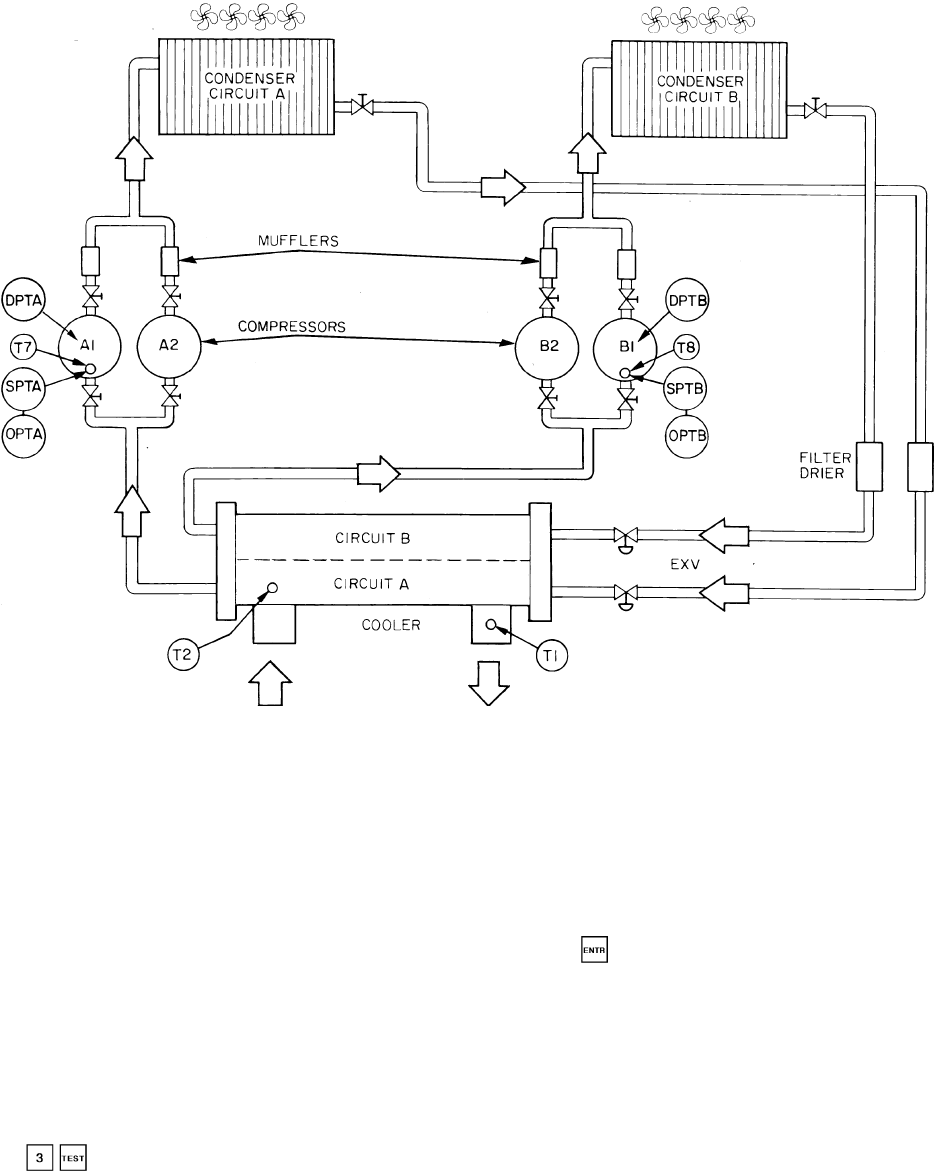
Pressure Transducers — A single style of pressure
transducer is used for both high- and low-pressure sensing
on Flotronic™ II chillers. However, this transducer must be
calibrated before the unit will operate. On new units, this
will have been done at the factory in order to test run the
unit. If a transducer or PSIO is replaced in the field, how-
ever, the transducer will have to be field calibrated as
follows:
1. Disconnect transducer from the system.
2. Hang the transducer in the atmosphere.
3. Press on the HSIO keypad, and Read the pres-
sure. Pressures before calibration must be within the
range of 65 psig. If the pressure is outside the range of
65 psig, the HSIO display will read ---. If this is the
case, replace the transducer or PSIO or check for a wir-
ing error. If the value of the atmospheric pressure is greater
than 5 psig or less than –5 psig, the transducer will be
considered out of range and will not calibrate.
4. Press on the HSIO keypad. This automatically ap-
plies the proper correction factor to all future inputs from
the transducer.
Three pressure transducers are mounted on each lead com-
pressor: 2 low-pressure transducers to monitor compressor
suction pressure and oil pressure, and a high-pressure trans-
ducer to monitor compressor discharge pressure (see
Fig. 17 for exact locations on compressor). Each transducer
is supplied with 5 vdc power from a rectifier which changes
24 vac to 5 vdc.
TROUBLESHOOTING — If transducer is suspected of be-
ing faulty, first check supply voltage to transducer. Supply
voltage should be 5 vdc ± .2 v. If supply voltage is correct,
compare pressure reading displayed on keypad and display
module against pressure shown on a calibrated pressure gage.
If the 2 pressure readings are not reasonably close, replace
pressure transducer.
LEGEND
DPT — Discharge Pressure Transducer
EXV — Electronic Expansion Valve
OPT — Oil Pressure Transducer
SPT — Suction Pressure Transducer
T—Thermistor Number
Fig. 14 — Thermistor and Pressure Transducer Locations
60
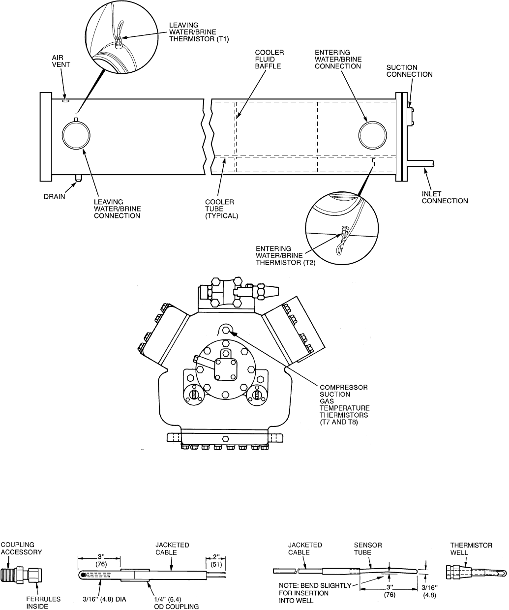
Fig. 15 — Thermistor Locations
(Circuits A and B, Lead Compressor Only)
FLUID-SIDE TEMPERATURE THERMISTOR T2
(ALL UNITS)
COMPRESSOR SUCTION GAS TEMPERATURE
THERMISTORS T7 AND T8
(ALL UNITS) AND FLUID-SIDE TEMPERATURE
THERMISTOR T1 (ALL UNITS)
Fig. 16 — Thermistors
61
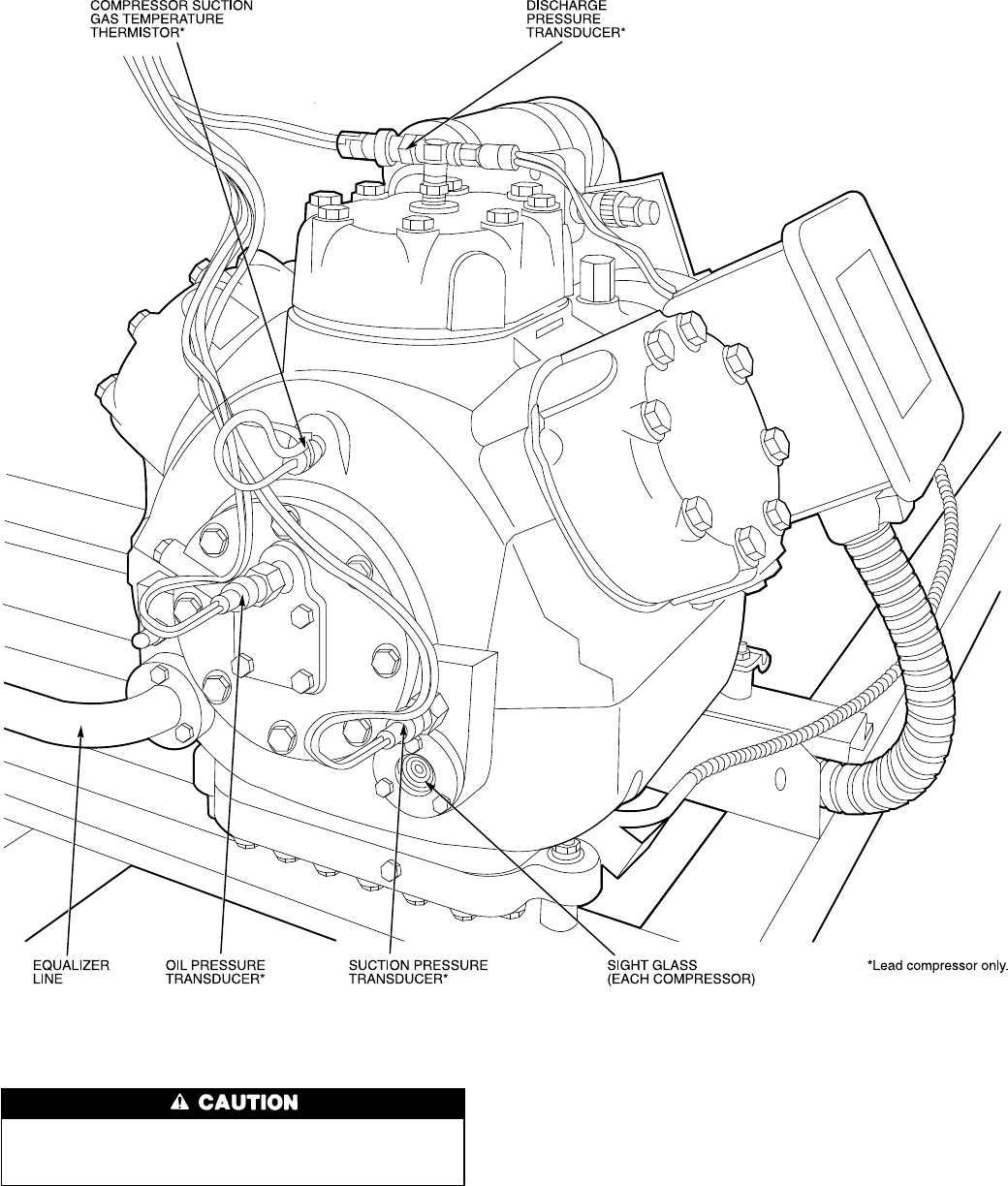
TRANSDUCER REPLACEMENT
Transducers are installed directly in the refrigerant cir-
cuit. Relieve all refrigerant pressure using standard re-
frigeration practices before removing.
1. Relieve refrigerant pressure using standard refrigeration
practices.
2. Disconnect transducer wiring at transducer by pulling up
on locking tab while pulling weathertight connection plug
from end of transducer. Do not pull on transducer wires.
3. Unscrew transducer from
1
⁄
4
-in. male flare fitting. When
installing new pressure transducer, do not use thread
sealer. Thread sealer can plug transducer and render it
inoperative.
4. Insert weathertight wiring plug into end of transducer un-
til locking tab snaps in place.
5. Check for refrigerant leaks.
Fig. 17 — Lead Compressor Transducer and Thermistor Locations
62
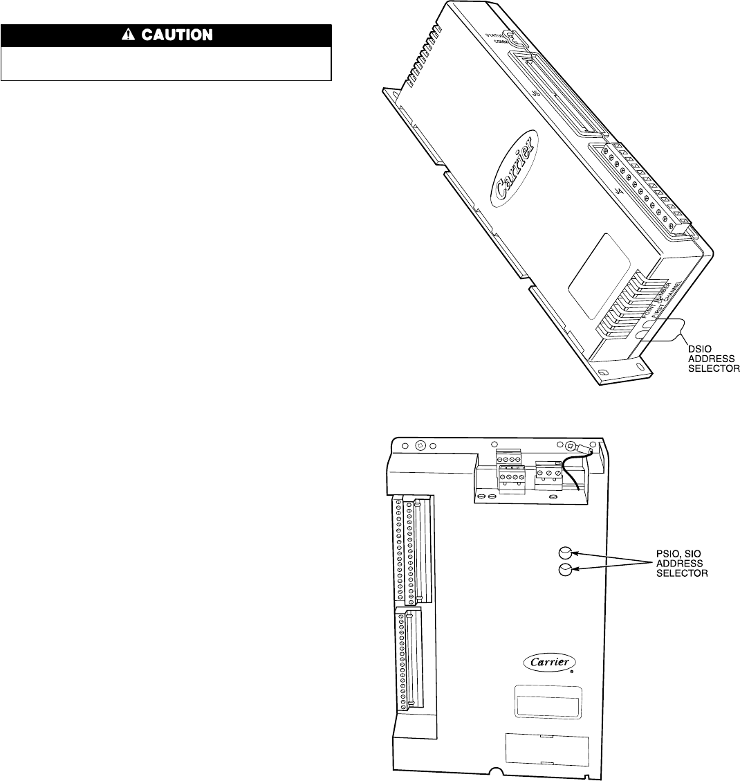
Control Modules
Turn controller power off before servicing controls. This
ensures safety and prevents damage to controller.
PROCESSOR MODULE (PSIO), 4 IN/4 OUT MODULE
(SIO), LOW-VOLTAGE RELAY MODULE (DSIO-LV),
AND EXV DRIVER MODULE (DSIO-EXV) — The PSIO,
DSIO and SIO modules all perform continuous diagnostic
evaluations of the condition of the hardware. Proper opera-
tion of these modules is indicated by LEDs (light-emitting
diodes) on the front surface of the DSIOs, and on the top
horizontal surface of the PSIO and SIO.
RED LED — Blinking continuously at a 3- to 5-second rate
indicates proper operation. Lighted continuously indicates a
problem requiring replacement of module. Off continuously
indicates power should be checked. If there is no input power,
check fuses. If fuse is bad, check for shorted secondary of
transformer or for bad module. On the PSIO module, if the
light is blinking at a rate of twice per second, the module
should be replaced.
GREEN LED — On a PSIO and an SIO, this is the green
LED closest to COMM connectors. The other green LED on
module indicates external communications, when used. Green
LED should always be blinking when power is on. It indi-
cates modules are communicating properly. If green LED is
not blinking, check red LED. If red LED is normal, check
module address switches. See Fig. 18. Proper addresses are:
PSIO (Processor Module) — 01 (different when CCN
connected)
DSIO (Relay Module) — 19
DSIO (EXV Driver Module) — 31
SIO (4 In/4 Out Module) — 59
If all modules indicate communication failure, check COMM
plug on PSIO module for proper seating. If a good connec-
tion is assured and condition persists, replace PSIO module.
If only DSIO or SIO module indicates communication fail-
ure, check COMM plug on that mode for proper seating. If
a good connection is assured and condition persists, replace
DSIO or SIO module.
All system operating intelligence rests in PSIO module,
the module that controls unit. This module monitors condi-
tions through input and output ports and through DSIO mod-
ules (low-voltage relay module and EXV driver module).
The machine operator communicates with microproces-
sor through keypad and display module. Communication be-
tween PSIO and other modules is accomplished by a 3-wire
sensor bus. These 3 wires run in parallel from module to
module.
On sensor bus terminal strips, terminal 1 of PSIO module
is connected to terminal 1 of each of the other modules.
Terminals 2 and 3 are connected in the same manner. See
Fig. 19. If a terminal 2 wire is connected to terminal 1, sys-
tem does not work.
In Flotronic™ II chillers, processor module, low-voltage
relay module, and keypad and display module are all pow-
ered from a common 21-vac power source which connects
to terminals 1 and 2 of power input strip on each module. A
separate source of 21-vac power is used to power options
module through terminals 1 and 2 on power input strip. A
separate source of 12.5 vac power is used to power EXV
driver module through terminals 1 and 2 on power input strip.
Fig. 18 — Module Address
Selector Switch Locations
63
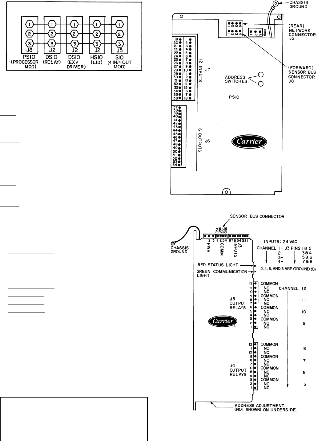
PROCESSOR MODULE (PSIO) (Fig. 20)
Inputs — Each input channel has 3 terminals; only 2 of the
terminals are used. Application of machine determines which
terminals are used. Always refer to individual unit wiring
for terminal numbers.
Outputs — Output is 24 vdc. There are 3 terminals, only 2
of which are used, depending on application. Refer to unit
wiring diagram.
NOTE: Address switches (see Fig. 20) must be set at 01 (dif-
ferent when CCN connected).
LOW VOLTAGE RELAY MODULE (DSIO-LV) (Fig. 21)
Inputs — Inputs on strip J3 are discrete inputs (ON/OFF).
When 24-vac power is applied across the 2 terminals in a
channel it reads as on signal. Zero v reads as an off signal.
Outputs — Terminal strips J4 and J5 are internal relays whose
coils are powered-up and powered-off by a signal from
microprocessor. The relays switch the circuit to which they
are connected. No power is supplied to these connections by
DSIO module.
4 IN/4 OUT MODULE (SIO) (Fig. 22) — 4 In/4 Out mod-
ule allows the following features to be utilized:
1. Temperature Reset by outdoor air or space temperature.
A remote thermistor (Part No. 30GB660002) is also re-
quired.
NOTE: This accessory is not required for return water
temperature reset.
2. Temperature Reset by remote 4 to 20 mA signal.
3. Demand Limit by remote 2-stage switch.
4. Demand Limit by remote 4 to 20 mA signal
5. Dual Set Point by remote switch.
The options module is standard. Remember to reconfig-
ure the chiller for each feature selected (see Table 14). For
temperature reset, demand limit, and dual set point, desired
set points must be entered through keypad and display mod-
ule (see Set Point Function section on page 38).
See Table 19 for overall troubleshooting information.
ACCESSORY UNLOADER INSTALLATION
Some of the 30G Flotronic™ II units come standard with
unloader(s), and many permit additional unloader(s) to be
added if desired. See Table 20.
IMPORTANT: The following combinationsARE NOT
permitted (combinations are per circuit):
1. Two unloaders and hot gas bypass
2. Four compressors and 2 unloaders.
3. Four compressors, 1 unloader, and hot gas
bypass.
Fig. 19 — Sensor Bus Wiring
(Communications)
PWR — Power
Fig. 20 — Processor Module (PSIO)
LEGEND
COMM — Communications Bus
NC — Normally Closed NO — Normally Open
PWR — Power
Fig. 21 — Low-Voltage Relay Module (DSIO)
64
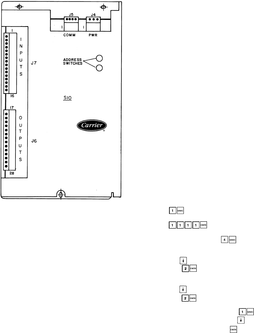
If accessory unloaders are desired, an accessory unloader
package is used. Package includes a suction cutoff unloader
head package. The 24-v coil in the package can be used
for 040-110, 130 (60 Hz), and associated modular units
(Table 1). A 115 v or 230 v coil must be used for 130
(50 Hz), 150-210, and associated modular units (Table 1).
Coil voltage depends on control circuit voltage. Consult cur-
rent Carrier price pages for appropriate part numbers.
NOTE: The accessory package will include all necessary com-
ponents and wiring with the following exceptions: The field
must provide screws, and on the 130-210, and associated modu-
lar units, the field must also supply a 20 vdc (part number
HK35AB001) unloader relay and wire (90° C or
equivalent).
Installation
1. Be sure all electrical disconnects are open and tagged be-
fore any work begins. Inspect the package contents for
any damage during shipping. File a claim with the ship-
per if damage has occurred.
2. For ease of installation, factory-supplied wiring for the
additional unloader is provided in the compressor
harness.
3. Install the additional unloader cylinder head on the lead
compressor, A1 or B1, according to instructions provided
by the compressor manufacturer in the accessory
package.
4. Continue installation per either 040-110, 130 (60 Hz) units
or 130 (50 Hz), 150-210 units section as appropriate.
040-110, 130 (60 Hz) UNITS (And Associated Modular Units)
1. Wire the solenoid before any field wiring begins. Wiring
between components and control box must be enclosed
in conduit. All local electrical codes and National Elec-
trical Code (NEC) must be followed. Factory wires are
provided in the compressor harness to connect the sole-
noid. These wires are in the compressor control box.
2. Wire the control side. Open the left side control box door
and remove inner panel. Using the holes provided and
field-supplied screws, install field-supplied transformer above
the DSIO-LV on the control panel.
Wire the primary side of the transformer in parallel with
TRAN4. See Fig. 23. This supplies transformer with proper
line voltage. Be sure to connect proper tap of the trans-
former to ensure supply of proper secondary voltage.
Wire the secondary side of transformer to DSIO-LV - J5-9,
and a jumper from DSIO-LV - J5-9 to DSIO-LV - J4-9.
Wire the secondary common to TB7-2. Connect the trans-
former ground to ground hole supplied near the trans-
former. These connections provide DSIO with necessary
power to energize the solenoid coils.
3. When all connections are made, check for proper wiring
and tight connections. Replace and secure inner panel.
Restore power to unit.
4. Configure the processor. With the addition of extra un-
loaders, the unit configuration has changed. To change
the configuration of the processor, enter the service func-
tion using the keypad and display module. Before any
changes can be made, the LOCAL/ENABLE-STOP-
CCN switch must be in the STOP position, and the ser-
vicer must log on to the processor.
a. Press . Keypad LCD displays the word
PASSWORD.
b. Enter . Keypad LCD displays
LOGGEDON.
c. To change configuration, press . Keypad LCD
displays FLD CFG.
d. If an additional unloader was added to compressor
A1, press until NULA 1 appears in keypad dis-
play. Press for the number of unloaders on
circuit A. Keypad display now reads NULA 2.
e. If an additional unloader was added to compressor
B1, press until NULB 1 appears in keypad dis-
play. Press for the number of unloaders on
circuit B. Keypad display now reads NULB 2.
f. When configuration is complete, press . Key-
pad display reads LOGGEDON. Press until key-
pad display reads LOG OFF. Press . Keypad dis-
play reads EXIT LOG.
LEGEND
COMM — Communications Bus
PWR — Power
Fig. 22 — 4 In/4 Out Module (SIO)
65

Table 19 — Troubleshooting
SYMPTOMS CAUSE REMEDY
COMPRESSOR DOES
NOT RUN Power line open Reset circuit breaker.
Control fuse open Check control circuit for ground or short.
Replace fuse.
High-Pressure Switch (HPS)
tripped Move LOCAL/ENABLE-STOP-CCN switch to STOP
position then back to RUN or CCN position.
Tripped power breaker Check the controls. Find cause of trip
and reset breaker.
Loose terminal connection Check connections.
Improperly wired controls Check wiring and rewire.
Low line voltage Check line voltage. Determine location
of voltage drop and remedy deficiency.
Compressor motor defective Check motor winding for open or short.
Replace compressor if necessary.
Seized compressor Replace compressor.
COMPRESSOR CYCLES OFF
ON LOW PRESSURE Loss of charge Repair leak and recharge.
Bad transducer Replace transducer.
Low refrigerant charge Add refrigerant.
COMPRESSOR SHUTS DOWN
ON HIGH PRESSURE
CONTROL
High-pressure control erratic in action Replace control.
Compressor discharge valve partially closed Open valve or replace if defective.
Condenser fan(s) not operating Check wiring. Repair or replace motor(s)
if defective.
Condenser coil plugged or dirty Clean coil.
UNIT OPERATES LONG OR
CONTINUOUSLY Low refrigerant charge Add refrigerant.
Control contacts fused Replace control.
Partially plugged or plugged expansion
valve or filter driver Clean or replace.
Defective insulation Replace or repair.
Service load Keep doors and windows closed.
Inefficient compressor Check valves. Replace if necessary.
SYSTEM NOISES Piping vibration Support piping as required.
Expansion valve hissing Add refrigerant.
Check for plugged liquid line filter drier.
Compressor noisy Check valve plates for valve noise.
Replace compressor (worn bearings).
Check for loose compressor holddown bolts.
COMPRESSOR LOSES OIL Leak in system Repair leak.
Mechanical damage (blown piston or
broken discharge valve) Repair damage or replace compressor.
Crankcase heaters not energized
during shutdown Replace heaters, check wiring and
crankcase heater relay contacts.
FROSTED SUCTION LINE Expansion valve admitting either too
much or too little refrigerant Check cooler and compressor thermistors.
Test EXV.
HOT LIQUID LINE Shortage of refrigerant due to leak Repair leak and recharge.
FROSTED LIQUID LINE Shutoff valve partially closed or restricted Open valve or remove restriction.
COMPRESSOR DOES NOT
UNLOAD Burned out coil Replace coil.
Defective capacity control valve Replace valve.
Miswired solenoid Rewire correctly.
Weak, broken, or wrong valve body spring Replace spring
COMPRESSOR DOES NOT
LOAD Miswired solenoid Rewire correctly.
Defective capacity control valve Replace valve.
Plugged strainer (high side) Clean or replace strainer.
Stuck or damaged unloader piston or
piston ring(s) Clean or replace the necessary parts.
EXV — Electronic Expansion Valve
Table 20 — Standard and Accessory Unloaders
UNIT NO. OF STANDARD
UNLOADER(s)
NO. OF ACCESSORY
UNLOADERS
PERMITTED
Circuit A Circuit B
30GN040-070 1 1 1or2
30GN080-170* 211
30GN190-210* 011
*And associated modular units.
66
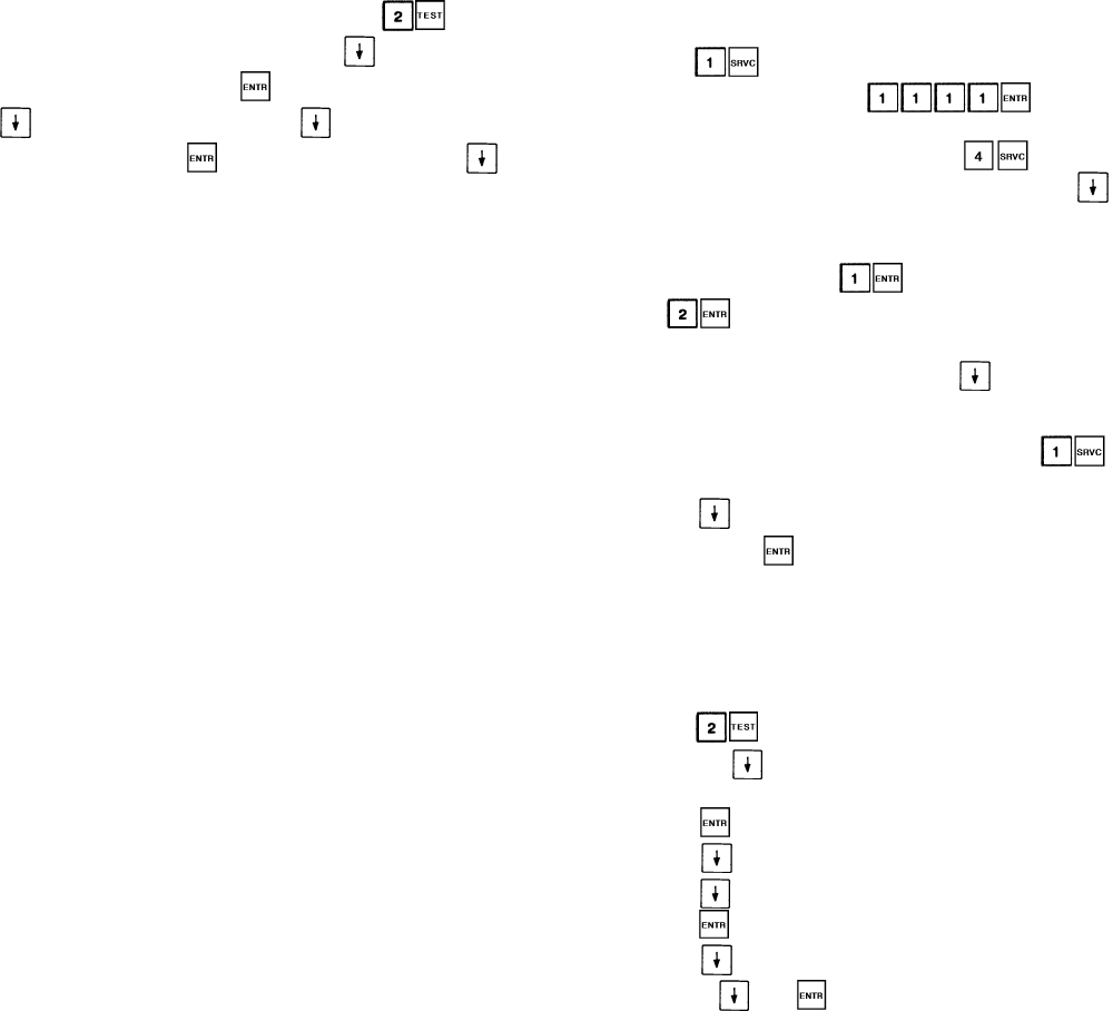
5. Using test function, check unloaders. Press . Key-
pad display reads OUTPUTS. Press until display
reads UNA2 OFF. Press . Relay energizes. Press
and relay deenergizes. Press until display reads
UNB2 OFF. Press . Relay energizes. Press
and relay deenergizes.
6. When unloader check has been performed, return LOCAL/
ENABLE-STOP-CCN to proper position. Close and se-
cure control box door.
130 (50 Hz), 150-210 UNITS (AndAssociated Modular Units)
1. Install control wiring. The minimum wire size for instal-
lation is 16 AWG (American Wire Gage). Refer to
Fig. 23 and 24 for proper wiring. Open the control box
door. Locate unloader relays A and B (UA, UB) in place
of the hot gas bypass relays as shown on the component
arrangement diagram on the unit. Mount the relays with
the field-supplied screws. Be careful not to damage the
components and wiring in the area when mounting the
relays.
2. Wire the control side. Wire the UA coil in series between
J6-18 and J6-19 of the 4 IN/4 OUT module with the wires
provided. Wire the UB coil in series between J6-21 and
J6-22 of the same module with the wires provided.
Locate the black wire in the control harness originating
from TRAN5 labeled HGBPR-A-COM. Connect this wire
to the UAterminal COM. Connect the wire labeled HGBPR-
A-NO to UA-NO. Connect the wire from UA-NO to
TB3-5. For an extra unloader on circuit B, connect the
wire labeled HGBPR-B-COM to UR-B-COM, and the wire
labeled HGBPR-B-NO to UB-NO. Connect the wire from
UB-NO to TB3-6.
3. Wire in the solenoid valves.
NOTE: Wires external to the control box must be run in
conduit.
Terminal blocks are provided for easy field wiring. Use
one of the isolated
7
⁄
8
-in. (22-mm) holes in the side of the
compressor electrical box with a strain relief to run the
wires to the solenoid coil. Connect UA between TB3-5
and TB3-8. Connect UB between TB3-6 and TB3-8. Check
all of the electrical connections for proper location and
tightness, and replace and secure the electrical box of the
compressor.
4. Configure the microprocessor. Once the relays are mounted
in the control box, the microprocessor must be config-
ured for the unloader option. To do so:
a. Be sure the LOCAL/ENABLE-STOP-CCN switch is
in the STOP position.
b. Log into the processor and enter the service func-
tion using the keypad and display module.
Press . The keypad LCD will display
‘‘PASSWORD.’’ Enter , and the
keypad LCD will display ‘‘LOGGEDON.’’
c. To change the configuration, press , and the
keypad LCD will display ‘‘FLD CFG.’’ Press
until either ‘‘NULA 0’’ or ‘‘NULA 1’’ is displayed
(depending on the number of unloaders provided as
standard). Then press (for 1 unloader on A1)
or (for 2 unloaders on compressor A1). The
display will now read either ‘‘NULA 1’’ or
‘‘NULA 2,’’ as appropriate. Press to get to the
NULB display, and change this setting in the same man-
ner as with circuit A.
d. Once the configuration is complete, press ,
and the keypad LCD will display ‘‘LOGGEDON,’’
Press until the keypad LCD display reads ‘‘LOG
OFF.’’ Press and the keypad LCD will display
‘‘EXIT LOG.’’
5. Once the unloader heads are installed, the unit is checked
for leaks, and the system is prepared for operation per the
instructions for the compressor unloader head installa-
tion, check the output of the relays using the test function
as follows:
a. Press , and the display will read ‘‘COMP.’’
b. Press the to scroll down until the display reads
‘‘CPA1 OFF.’’
c. Press , and the compressor should start.
d. Press , and the compressor should stop.
e. Press until the display reads ‘‘UNA1 OFF.’’
f. Press , and the solenoid should energize.
g. Press and the solenoid should deenergize.
h. Use the and keys to check the remainder of
the unloader coils.
6. Once the check has been performed, return the LOCAL/
ENABLE-STOP-CCN switch to the proper position.
7. Close and secure the control box door.
8. Start the unit and confirm that the chiller operates
properly.
67
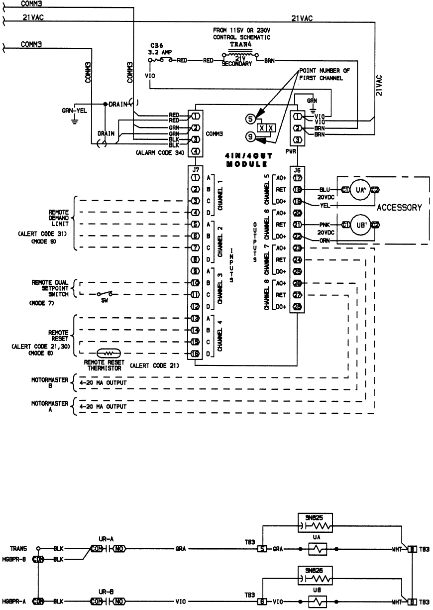
LEGEND
C—Contactor PWR — Power
CB — Circuit Breaker SW — Switch
COMM — Communications Bus TRAN — Transformer
HGBPR — Hot Gas Bypass Relay U—Unloader
*Or HGBPR-A.
†Or HGBPR-B.
LEGEND
COM — Communications Bus TB — Terminal Block
HGBPR — Hot Gas Bypass Relay TRAN — Transformer
NO — Normally Open U—Unloader
SNB — Snubber
Fig. 24 — Flotronic™ II 115/230-V (Unloader Wiring, 130 (50 Hz), 150-210 and Associated Modular Units
(See Table 1)
Fig. 23 — Accessory Unloader Control Wiring, All Units
68
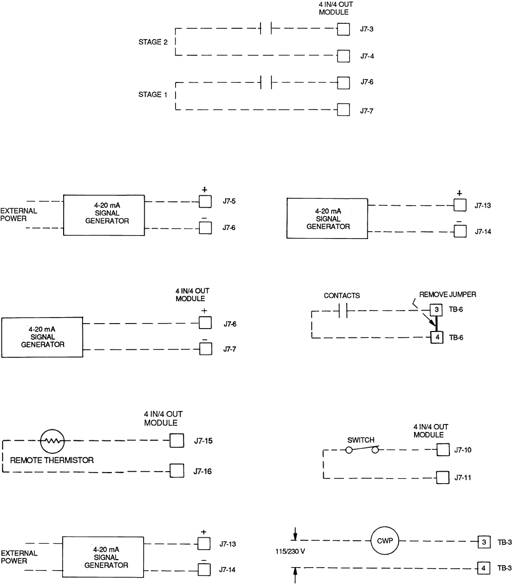
FIELD WIRING
Refer to Fig. 25-35 for field wiring.
NOTE: Contacts must be rated for dry circuit application, capable of
reliably switching a 5 vdc, 1 mA to 20 mA load.
Fig. 25 — Demand Limit — Two External
Switch Inputs
Fig. 26 − Demand Limit — 4-20 mA Signal
(Externally Powered)
Fig. 27 — Demand Limit — 4-20 mA Signal
(Internally Powered)
Fig. 28 — Remote Reset from Space or
Outdoor-Air Temperature
Fig. 29 — Remote Reset from 4-20 mA Signal
(Externally Powered)
Fig. 30 — Remote Reset from 4-20 mA Signal
(Internally Powered)
TB — Terminal Block
NOTE: Contacts must be rated for dry circuit application, capable of
reliably switching a 5 vdc, 1 mA to 20 mA load.
Fig. 31 — Remote On/Off
Fig. 32 — Remote Dual Set Point Control
CWP — Chilled Water (Fluid) Pump
TB — Terminal Block
Fig. 33 — Chilled Fluid Pump
69
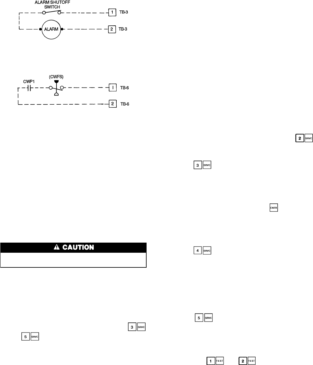
REPLACING DEFECTIVE
PROCESSOR MODULE
The replacement part number is printed on a small label
on the front of the PSIO module. The model and serial num-
bers are printed on the unit nameplate located on an exterior
corner post. The proper software and unit configuration data
is factory installed by Carrier in the replacement module.
Therefore, when ordering a replacement processor module
(PSIO), specify complete replacement part number, full unit
model number, and serial number. If these numbers are not
provided, the replacement module order is configured in-
stead as a generic Flotronic II replacement module. This re-
quires reconfiguration of the module by the installer.
Electrical shock can cause personal injury. Disconnect
all electrical power before servicing.
Installation
1. Verify the existing PSIO module is defective by using
the procedure described in the Control Modules section
on page 63.
2. Refer to Start-Up Checklist for Flotronic II Chiller Sys-
tems (completed at time of original start-up) found in
job folder. This information is needed later in this
procedure. If checklist does not exist, fill out the
and configuration code sections on a new check-
list. Tailor the various options and configurations as needed
for this particular installation.
3. Check that all power to unit is off. Carefully disconnect
all wires from defective module by unplugging the 6 con-
nectors. It is not necessary to remove any of the indi-
vidual wires from the connectors. Remove the green ground
wire.
4. Remove defective PSIO by removing its mounting screws
with a Phillips screwdriver, and removing the module
from the control box. Save the screws for later use.
5. Use a small screwdriver to set address switches S1 and
S2 on the new PSIO module to exactly match the set-
tings on the defective module.
6. Package the defective module in the carton of the new
module for return to Carrier.
7. Mount the new module in the unit control box using a
Phillips screwdriver and the screws saved in Step 4 above.
8. Reinstall all 6 wire connectors and the green ground wire.
9. Carefully check all wiring connections before restoring
power.
10. Verify the LOCAL/ENABLE-STOP-CCN switch is in
STOP position.
11. Restore control power. Verify the red and green lights
on top of PSIO and front of each DSIO module respond
as described in Control Modules section on page 63. The
keypad and display module should also begin its rotat-
ing display.
12. Using the keypad and display module, press
to verify that the software version number matches the
ER (engineering requirement) number shown on the PSIO
label.
13. Press to verify that the 7 factory configuration
codes (CODE 1 through CODE 7) exactly match the codes
listed for this unit model on the component arrangement
label diagram on the control box door. If they are dif-
ferent or are all zeros, reenter the 7 codes. If any changes
are required, the PSIO display becomes blank and
reconfigures itself after pressing the key while dis-
playing CODE 7. The display returns in approximately
15 seconds.
NOTE: Codes with leading zeros in the configuration
will be displayed starting with the first number greater
than zero.
14. Press to verify each item is configured as needed
for this particular installation. Table 14 shows the fac-
tory configuration code default settings. Table 14 also
shows the service replacement code default settings which
are used if no model number was specified when order-
ing the replacement PSIO module. It is strongly sug-
gested that the Start-Up Checklist for Flotronic II Chiller
Systems (completed at time of original start-up) be used
at this time to verify and/or reprogram the various op-
tions and configurations required for this job.
15. Press to verify that the 2 field configuration
codes (codes 8 and 9) match exactly the codes listed on
the label diagram on the control box door. If they are
different, or are all zeros, reenter the 2 codes.
16. After completing the configuration steps outlined above,
restore main power and perform a unit test as de-
scribed in and sections on page 38.
17. Complete this procedure and restore chiller to normal
operation by returning the LOCAL/ENABLE-STOP-
CCN switch to desired position.
TB — Terminal Block
Fig. 34 — Remote Alarm
CWP1 — Chilled Water (Fluid) Pump Interlock
CWFS — Chilled Water (Fluid) Flow Switch (not required — low flow
protection is provided by Flotronic™ II controls)
TB — Terminal Block
Fig. 35 — Interlocks
70

Copyright 1995 Carrier Corporation
Manufacturer reserves the right to discontinue, or change at any time, specifications or designs without notice and without incurring obligations.
Book 2
Tab 5c
PC 903 Catalog No. 563-079 Printed in U.S.A. Form 30GN-3T Pg 72 7-95 Replaces: 30G-1T
