Carrier Weathermaker 48Aj Users Manual 48a 7si
WEATHERMAKER 48AJ 48a-7si
48AJ to the manual 975003af-2aee-4ff9-b5c1-b978d00e0156
2015-01-24
: Carrier Carrier-Weathermaker-48Aj-Users-Manual-310531 carrier-weathermaker-48aj-users-manual-310531 carrier pdf
Open the PDF directly: View PDF ![]() .
.
Page Count: 36

Manufacturer reserves the right to discontinue, or change at any time, specifications or designs without notice and without incurring obligations.
Catalog No. 04-53480067-01 Printed in U.S.A. Form 48A-7SI Pg 1 8-09 Replaces: 48A-5SI
Installation Instructions
CONTENTS
Page
SAFETY CONSIDERATIONS . . . . . . . . . . . . . . . . . . . . . . 1
INSTALLATION . . . . . . . . . . . . . . . . . . . . . . . . . . . . . . . . 1-36
Step 1 — Provide Unit Support . . . . . . . . . . . . . . . . . . . 1
• ROOF CURB
• ALTERNATE UNIT SUPPORT
Step 2 — Rig and Place Unit . . . . . . . . . . . . . . . . . . . . . 2
• POSITIONING
• ROOF MOUNT
Step 3 — Field Fabricate Ductwork. . . . . . . . . . . . . . . 2
Step 4 — Make Unit Duct Connections . . . . . . . . . . . 2
Step 5 — Install Flue Hood . . . . . . . . . . . . . . . . . . . . . . 19
Step 6 — Trap Condensate Drain . . . . . . . . . . . . . . . . 19
Step 7 — Install Gas Piping . . . . . . . . . . . . . . . . . . . . . 19
Step 8 — Make Electrical Connections . . . . . . . . . . 20
•POWER WIRING
• FIELD POWER SUPPLY
• FIELD CONTROL WIRING
Step 9 — Make Outdoor-Air Inlet
Adjustments . . . . . . . . . . . . . . . . . . . . . . . . . . . . . . . . . . 32
• ECONOMIZER AND FIXED OUTDOOR
AIR DAMPER
Step 10 — Position Power Exhaust/Barometric
Relief Damper Hood. . . . . . . . . . . . . . . . . . . . . . . . . . . 33
Step 11 — Route VAV Static Pressure Sensor . . . 34
Step 12 — Install All Accessories . . . . . . . . . . . . . . . 35
Step 13 — Field Modifications. . . . . . . . . . . . . . . . . . . 35
SAFETY CONSIDERATIONS
Installation and servicing of air-conditioning equipment can
be hazardous due to system pressure and electrical compo-
nents. Only trained and qualified service personnel should in-
stall, repair, or service air-conditioning equipment.
Untrained personnel can perform the basic maintenance
functions of cleaning coils and filters and replacing filters. All
other operations should be performed by trained service per-
sonnel. When working on air-conditioning equipment, observe
precautions in the literature, tags and labels attached to the unit,
and other safety precautions that may apply.
Follow all safety codes. Wear safety glasses and work
gloves. Use quenching cloth for unbrazing operations. Have
fire extinguishers available for all brazing operations.
INSTALLATION
Step 1 — Provide Unit Support
WARNING
Before performing service or maintenance operations on
unit, turn off main power switch to unit. Electrical shock
could cause personal injury.
WARNING
1. Improper installation, adjustment, alteration, service,
or maintenance can cause property damage, personal
injury, or loss of life. Refer to the User’s Information
Manual provided with this unit for more details.
2. Do not store or use gasoline or other flammable va-
pors and liquids in the vicinity of this or any other
appliance.
What to do if you smell gas:
1. DO NOT try to light any appliance.
2. DO NOT touch any electrical switch, or use any
phone in your building.
3. IMMEDIATELY call your gas supplier from a neigh-
bor’s phone. Follow the gas supplier’s instructions.
4. If you cannot reach your gas supplier, call the fire
department.
WARNING
Disconnect gas piping from unit when pressure testing at
pressure greater than 0.5 psig. Pressures greater than
0.5 psig will cause gas valve damage resulting in hazardous
condition. If gas valve is subjected to pressure greater than
0.5 psig, it must be replaced before use. When pressure
testing field-supplied gas piping at pressures of 0.5 psig or
less, a unit connected to such piping must be isolated by
closing the manual gas valve(s).
CAUTION
1. All panels must be in place when rigging or damage
to unit may occur.
2. Unit is not designed for handling by fork truck.
WEATHERMAKER®
48AJ,AK,AW,AY020-060
Single Package Rooftop Units
Electric Cooling/Gas Heating
with Scroll Compressor and
COMFORTLINK™ Controls
2
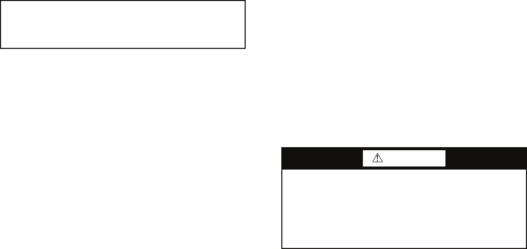
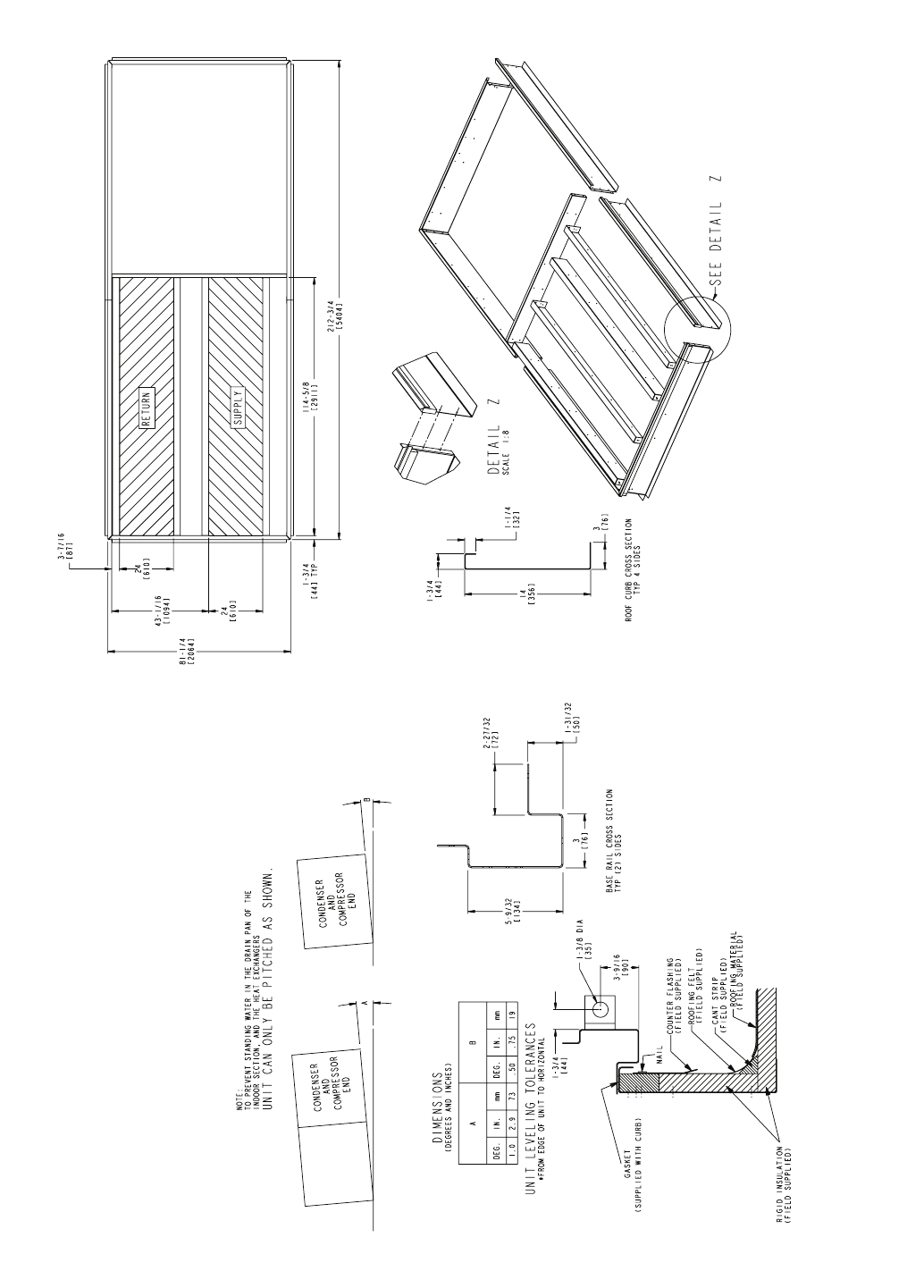
ROOF CURB — For vertical discharge units, assemble or in-
stall accessory roof curb in accordance with instructions
shipped with this accessory. See Fig. 1-3. Install insulation,
cant strips, roofing, and counter flashing as shown. Ductwork
can be installed to roof curb before unit is set in place. Curb
should be level. This is necessary to permit unit drain to func-
tion properly. Unit leveling tolerance is shown in Fig. 1-3.
Refer to Accessory Roof Curb Installation Instructions for
additional information as required. When accessory roof curb
is used, unit may be installed on class A, B, or C roof covering
material.
ALTERNATE UNIT SUPPORT — When the preferred curb
or slab mount cannot be used, support unit with sleepers on pe-
rimeter, using unit curb support area. If sleepers cannot be
used, support long sides of unit (refer to Fig. 4-10) with a mini-
mum number of 4-in. x 4-in. pads spaced as follows:
48AJ,AK,AW,AY020-035 units require 3 pads on each side;
48AJ,AK,AW,AY036-050 units require 4 pads on each side;
48AJ,AK,AW,AY051 and 060 units require 6 pads on each
side. Unit may sag if supported by corners only.
Step 2 — Rig and Place Unit — Inspect unit for
transportation damage. See Tables 1-6 for physical data and
specifications. File any claim with transportation agency.
Do not drop unit; keep upright. Use spreader bars over unit
to prevent sling or cable damage. This unit must be handled
with a crane and can not be handled by a fork truck. Level by
using unit frame as a reference; leveling tolerance is shown in
Fig. 1-3. See Fig. 10 for additional information. Unit operating
weight is shown in Table 2.
NOTE: On retrofit jobs, ductwork may be attached to the old
unit instead of a roof curb. Be careful not to damage ductwork
when removing old unit. Attach existing ductwork to roof curb
instead of unit.
Four lifting lugs are provided on the unit base rails as shown
in Fig. 4-10. Refer to rigging instructions on unit.
POSITIONING — Maintain clearance, per Fig. 4-10, around
and above unit to provide minimum distance from combustible
materials, proper airflow, and service access.
Do not install unit in an indoor location. Do not locate unit
air inlets near exhaust vents or other sources of contaminated
air. For proper unit operation, adequate combustion and venti-
lation air must be provided in accordance with Section 5.3 (Air
for Combustion and Ventilation) of the National Fuel Gas
Code, ANSI Z223.1 (American National Standards Institute).
Although unit is weatherproof, guard against water from
higher level runoff and overhangs.
Locate mechanical draft system flue assembly at least 4 ft
from any opening through which combustion products could
enter the building, and at least 4 ft from any adjacent building.
When unit is located adjacent to public walkways, flue assem-
bly must be at least 7 ft above grade.
ROOF MOUNT — Check building codes for weight distribu-
tion requirements. See Fig. 11. Unit operating weight is shown
in Table 2.
Step 3 — Field Fabricate Ductwork — Secure all
ducts to building structure. Use flexible duct connectors be-
tween unit and ducts as required. Insulate and weatherproof all
external ductwork, joints, and roof openings with counter
flashing and mastic in accordance with applicable codes.
NOTE: Due to width of the horizontal supply and return duct-
work, provisions should be made for servicing of the outdoor
air filters (i.e., catwalk over ductwork).
Ducts passing through an unconditioned space must be in-
sulated and covered with a vapor barrier. Outlet grilles must not
lie directly below unit discharge. The return duct must have a
90-degree elbow before opening into the building space if the
unit is equipped with power exhaust.
To attach ductwork to roof curb, insert duct approximately
10 to 11 in. up into roof curb. Connect ductwork to 14-gage
roof curb material with sheet metal screws driven from inside
the duct.
Follow AMCA (Air Movement and Control Association)
guidelines relating to ductwork connections to the unit. These
guidelines recommend a minimum 21/2 equivalent duct diame-
ters of straight duct connected to supply air inlet and outlet
openings before any transitions, fittings, dampers, etc. Failure
to adhere to these guidelines may result in system effects which
can impact the unit’s ability to achieve published performance.
Step 4 — Make Unit Duct Connections
48AJ AND AK UNITS — Unit is shipped for thru-the-
bottom duct connections. Field-fabricated ductwork should be
attached to the roof curb. Supply and return duct dimensions
are shown in Fig. 4-6. Air distribution is shown in Fig. 12.
Refer to installation instructions shipped with roof curb for
more information.
48AW AND AY UNITS — Remove shipping covers from
supply and return air openings. Attach field-supplied ductwork
to unit. Connect to the unit with a single duct for all supply
openings and with a single duct for all return openings.
Splitting of the airflow into branch ducts should not be done at
the unit. Sufficient duct length should be used prior to branch-
ing to ensure the air temperatures are well mixed within the
ductwork. See Fig. 7-9 for duct opening dimensions. Secure all
ducts to building structure. Air distribution is shown in Fig. 7-9
and Fig. 13.
Install accessory barometric relief or power exhaust in the
field-fabricated return ductwork. Refer to Step 10 — Position
Power Exhaust/Barometric Relief Damper Hood section on
page 33 for more information.
Instructions continued on page 19.
IMPORTANT: The gasketing of the unit to the roof curb is
critical for a watertight seal. Install gasket with the roof
curb as shown in Fig. 1-3. Improperly applied gasket can
also result in air leaks and poor unit performance.
WARNING
For vertical supply and return units, tools or parts could
drop into ductwork and cause an injury. Install a 90-degree
elbow turn in the supply and return ductwork between the
unit and the conditioned space. If a 90-degree elbow cannot
be installed, then a grille of sufficient strength and density
should be installed to prevent objects from falling into the
conditioned space.

3
Fig. 1 — Roof Curb — 48AJ,AK020-035 Units
a48-6715
NOTES:
1. UNLESS OTHERWISE SPECIFIED, ALL DIMENSIONS ARE TO OUTSIDE OF PART.
2. ROOF CURB ACCESSORY CRRFCURB005A00 IS SHIPPED DISASSEMBLED.
3. ALL ROOF CURB PARTS ARE TO BE 14 GA. GALVANIZED STEEL.
4. UNITS WITH ELECTRIC HEAT MUST BE INSTALLED WITH A 90° ELBOW ON THE SUPPLY
DUCT PRIOR TO ANY SUPPLY TAKE OFFS OR BRANCHES.
5. DIMENSIONS IN [ ] ARE IN MILLIMETERS. ALL OTHER DIMENSIONS ARE IN INCHES.
4
Fig. 2 — Roof Curb — 48AJ,AK036-050 Units
a48-6716
NOTES:
1. UNLESS OTHERWISE SPECIFIED, ALL DIMENSIONS ARE TO OUTSIDE OF PART.
2. ROOF CURB ACCESSORY CRRFCURB005A00 IS SHIPPED DISASSEMBLED.
3. ALL ROOF CURB PARTS ARE TO BE 14 GA. GALVANIZED STEEL.
4. UNITS WITH ELECTRIC HEAT MUST BE INSTALLED WITH A 90° ELBOW ON THE SUPPLY
DUCT PRIOR TO ANY SUPPLY TAKE OFFS OR BRANCHES.
5. DIMENSIONS IN [ ] ARE IN MILLIMETERS. ALL OTHER DIMENSIONS ARE IN INCHES.
5
Fig. 3 — Roof Curb — 48AJ,AK051 and 060 Units
a48-6717
NOTES:
1. UNLESS OTHERWISE SPECIFIED, ALL DIMENSIONS ARE TO
OUTSIDE OF PART.
2. ROOF CURB ACCESSORY CRRFCURB005A00 IS SHIPPED DIS-
ASSEMBLED.
3. ALL ROOFCURB PARTS ARE TO BE 14 GA. GALVANIZED STEEL.
4. DIMENSIONS IN [ ] ARE IN MILLIMETERS. ALL OTHER DIMEN-
SIONS ARE IN INCHES.
6
* OPERATING WEIGHT INCLUDES LARGEST INDOOR FAN MOTOR, CU/AL COILS,
MODULATING POWER EXHAUST (VARIABLE AIR VOLUME), AND VARIABLE
FREQUENCY DRIVE (VARIABLE AIR VOLUME).
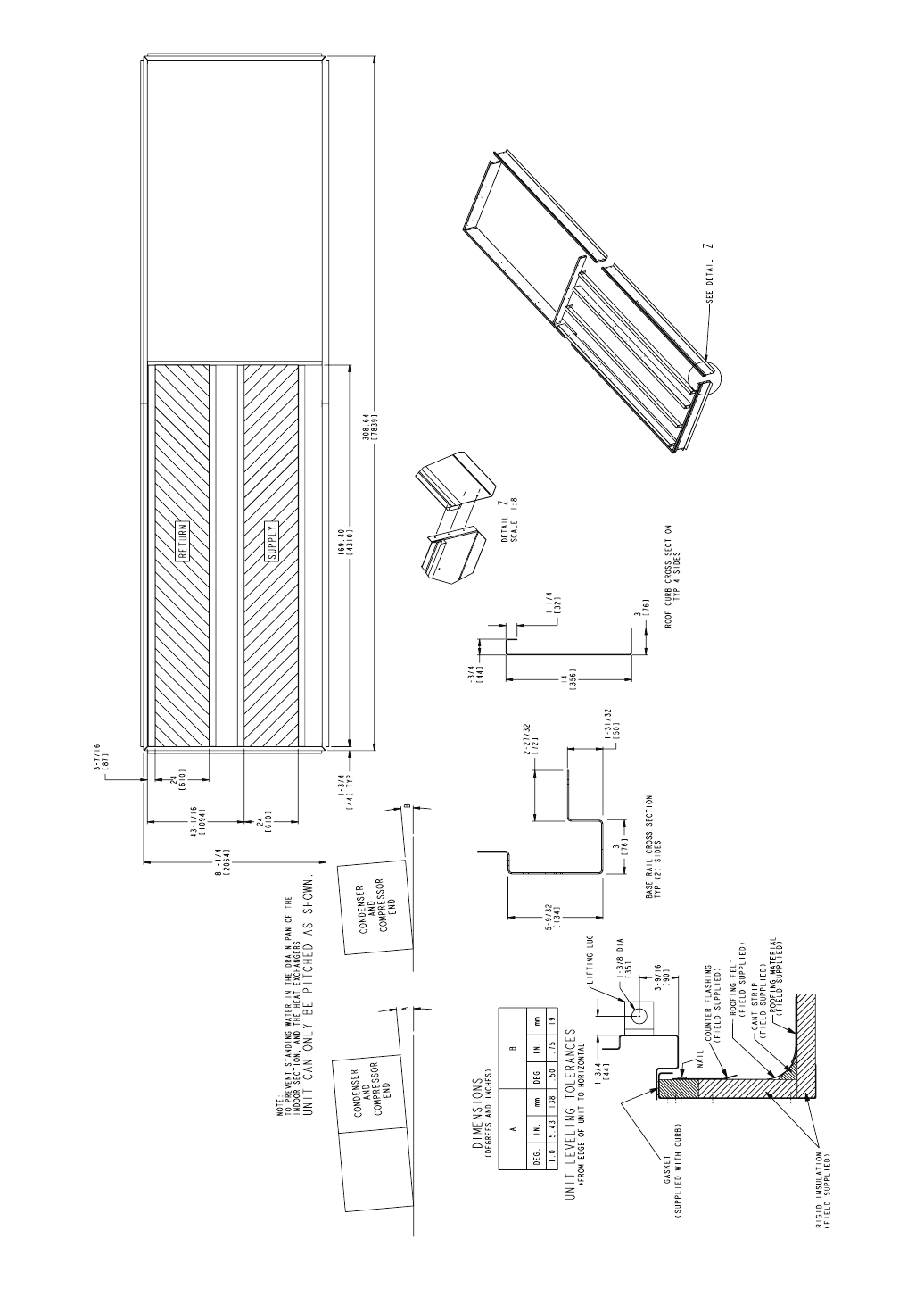
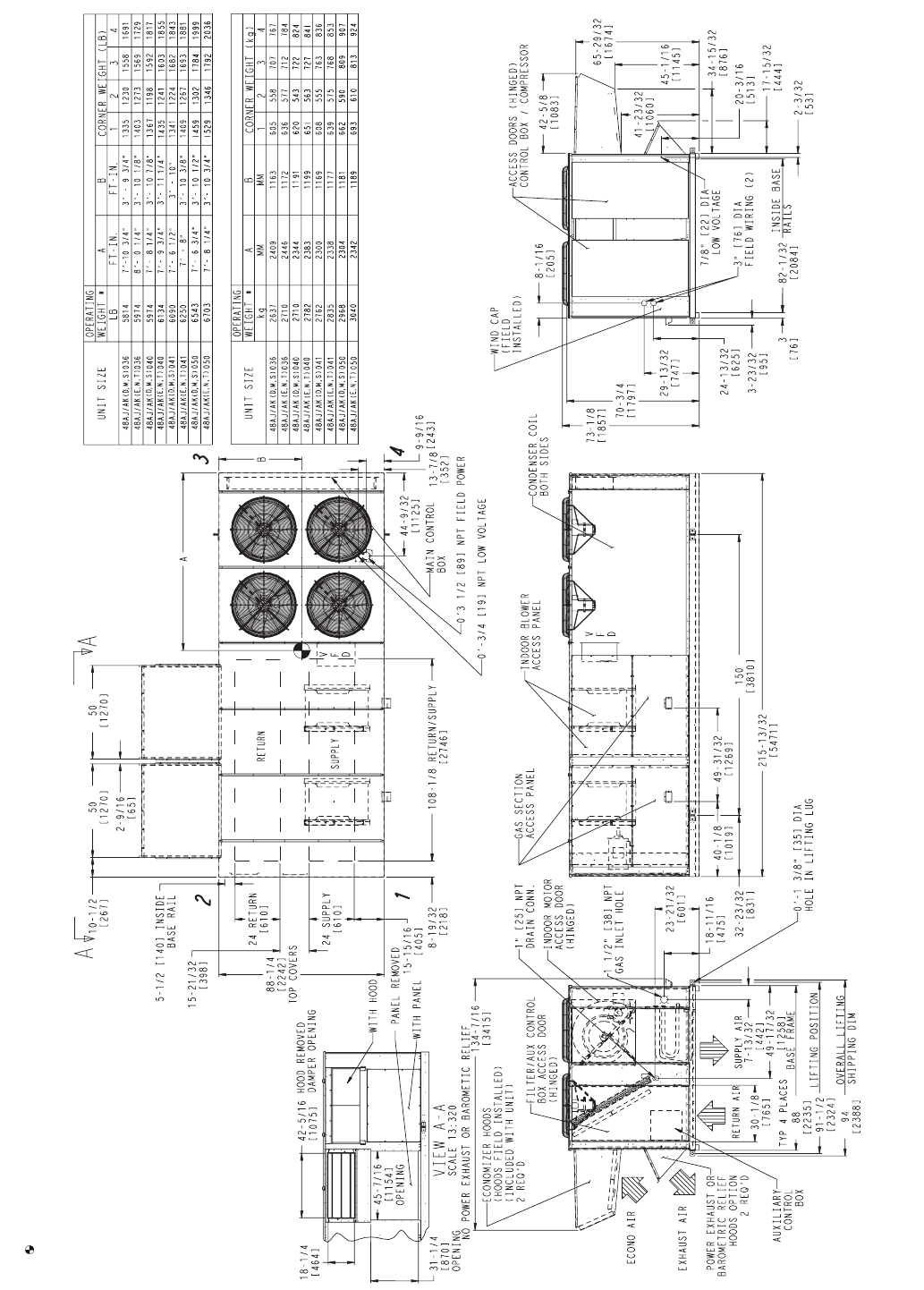
Fig. 4 — Base Unit Dimensions — 48AJ,AK020-035
a48-8235
NOTES:
1. WEIGHTS INCLUDE ECONOMIZER (STD).
2. CENTER OF GRAVITY.
3. UNIT CLEARANCES:
TOP OF UNITS: NO OVERHANG
CONDENSER COIL: 4’ - 0“ [1219]
ECONOMIZER SIDE: 6’ - 0” [1829]
HEAT SIDE: 4’’ - 0” [1219]
FILTER ACCESS SIDE: 10’ - 0” [3048] (FOR
REMOVAL OF EVAPORATOR COIL)
4. FOR SMALLER SERVICE AND OPERATIONAL
CLEARANCES, CONTACT CARRIER APPLICA-
TION ENGINEERING DEPARTMENT.
5. BOTTOM DUCTS ARE DESIGNED TO BE AT-
TACHED TO ACCESSORY ROOF CURB. IF UNIT
IS MOUNTED ON DUNNAGE, IT IS RECOM-
MENDED THAT THE DUCTS BE SUPPORTED
BY CROSS BRACES AS DONE ON ACCESSO-
RY ROOF CURB.
6. DIMENSIONS IN [ ] ARE IN MILLIMETERS. ALL
OTHER DIMENSIONS ARE IN INCHES.
7
* OPERATING WEIGHT INCLUDES LARGEST INDOOR FAN MOTOR, CU/AL COILS,
MODULATING POWER EXHAUST (VARIABLE AIR VOLUME), AND VARIABLE
FREQUENCY DRIVE (VARIABLE AIR VOLUME).
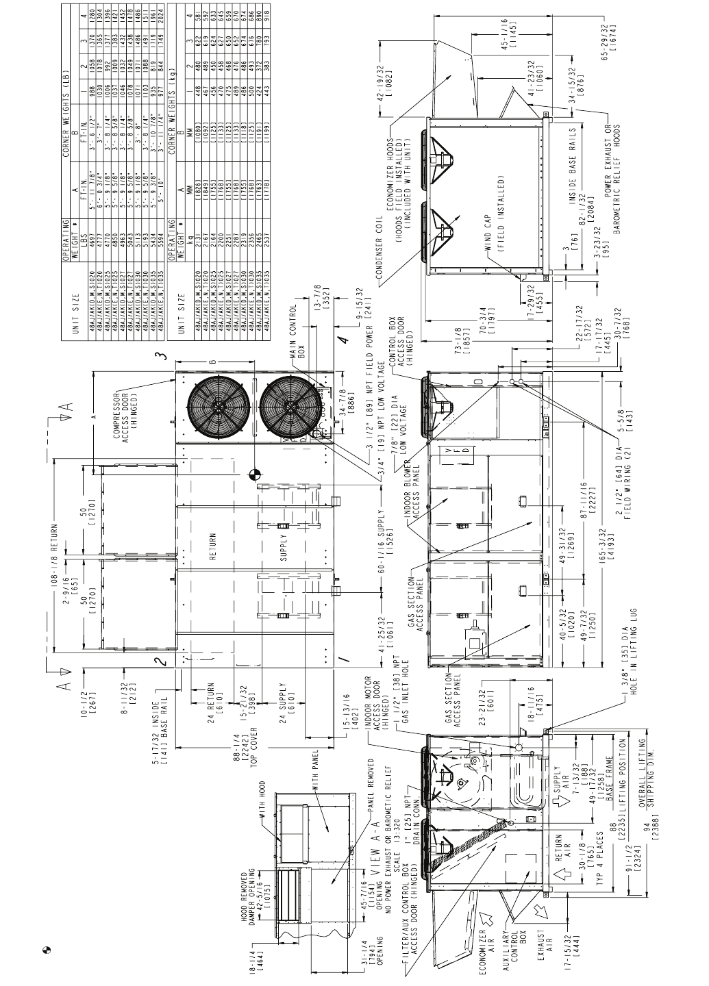
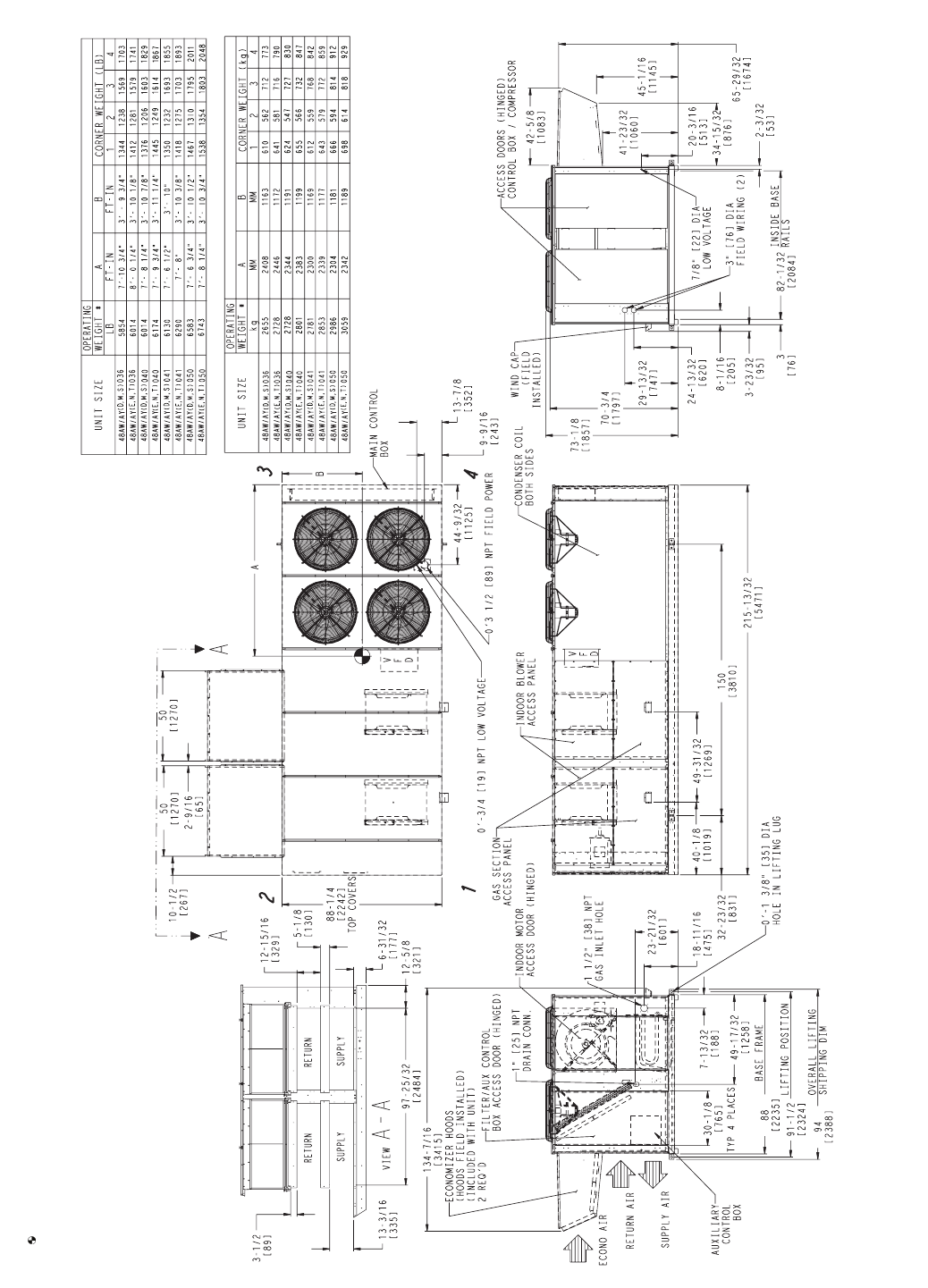
Fig. 5 — Base Unit Dimensions — 48AJ,AK036-050
a48-8236
N
OTES:
1. WEIGHTS INCLUDE ECONOMIZER (STD).
2. CENTER OF GRAVITY.
3. UNIT CLEARANCES:
TOP OF UNITS: NO OVERHANG
CONDENSER COIL: 4’ - 0“ [1219]
ECONOMIZER SIDE: 6’ - 0” [1829]
HEAT SIDE: 4’’ - 0” [1219]
FILTER ACCESS SIDE: 10’ - 0” [3048] (FOR
REMOVAL OF EVAPORATOR COIL)
4. FOR SMALLER SERVICE AND OPERATIONAL
CLEARANCES, CONTACT CARRIER APPLICA-
TION ENGINEERING DEPARTMENT.
5. BOTTOM DUCTS ARE DESIGNED TO BE AT-
TACHED TO ACCESSORY ROOF CURB. IF UNIT
IS MOUNTED ON DUNNAGE, IT IS RECOM-
MENDED THAT THE DUCTS BE SUPPORTED BY
CROSS BRACES AS DONE ON ACCESSORY
ROOF CURB.
6. DIMENSIONS IN [ ] ARE IN MILLIMETERS. ALL
OTHER DIMENSIONS ARE IN INCHES.
8
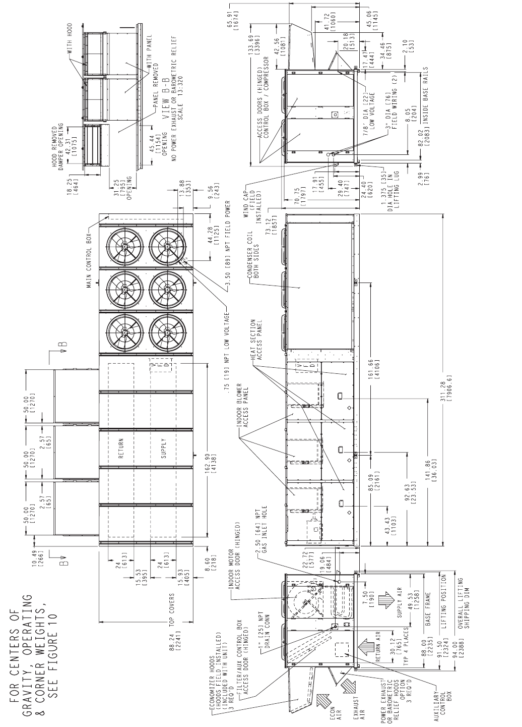
Fig. 6 — Base Unit Dimensions — 48AJ,AK051 and 060
9
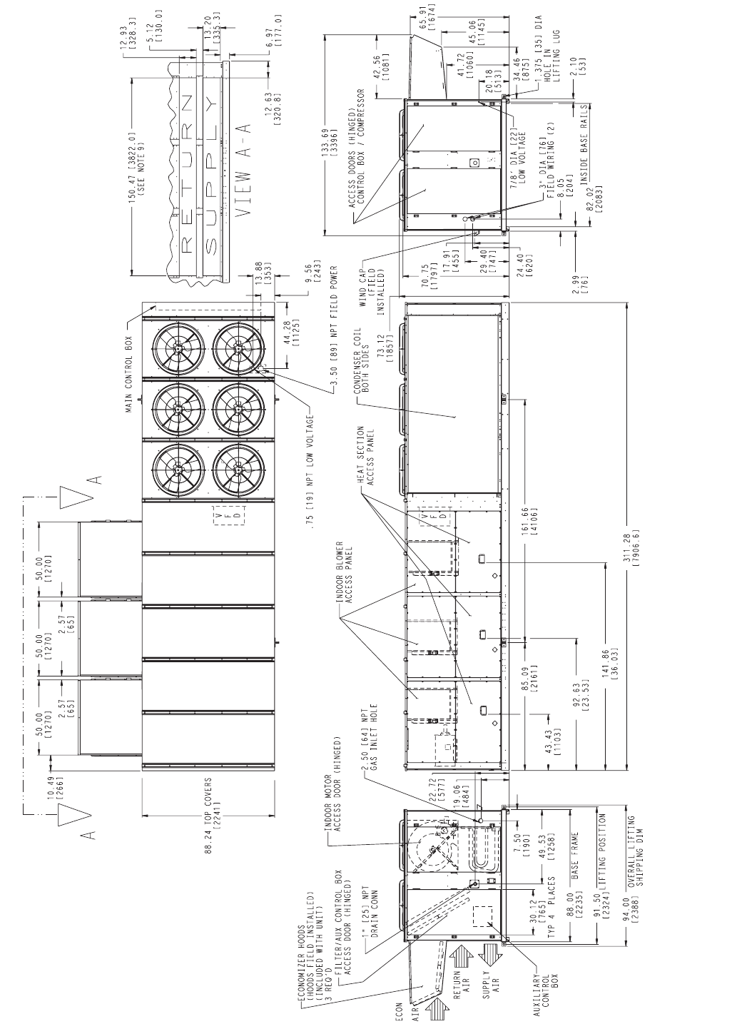
Fig. 7 — Base Unit Dimensions — 48AW,AY020-035
A48-8380
NOTES:
1. WEIGHTS INCLUDE ECONOMIZER (STD).
2. CENTER OF GRAVITY.
3. UNIT CLEARANCES:
TOP OF UNITS: NO OVERHANG
CONDENSER COIL: 4’ - 0“ [1219]
ECONOMIZER SIDE: 6’ - 0” [1829]
HEAT SIDE: 4’’ - 0” [1219]
FILTER ACCESS SIDE: 10’ - 0” [3048] (FOR REMOVAL OF
EVAPORATOR COIL)
4. FOR SMALLER SERVICE AND OPERATIONAL CLEARANCES,
CONTACT CARRIER APPLICATION ENGINEERING
DEPARTMENT.
5. DIMENSIONS IN [ ] ARE IN MILLIMETERS. ALL OTHER DIMEN-
SIONS ARE IN INCHES.
10
* OPERATING WEIGHT INCLUDES LARGEST INDOOR FAN MOTOR, CU/AL COILS,
MODULATING POWER EXHAUST (VARIABLE AIR VOLUME), AND VARIABLE
FREQUENCY DRIVE (VARIABLE AIR VOLUME).
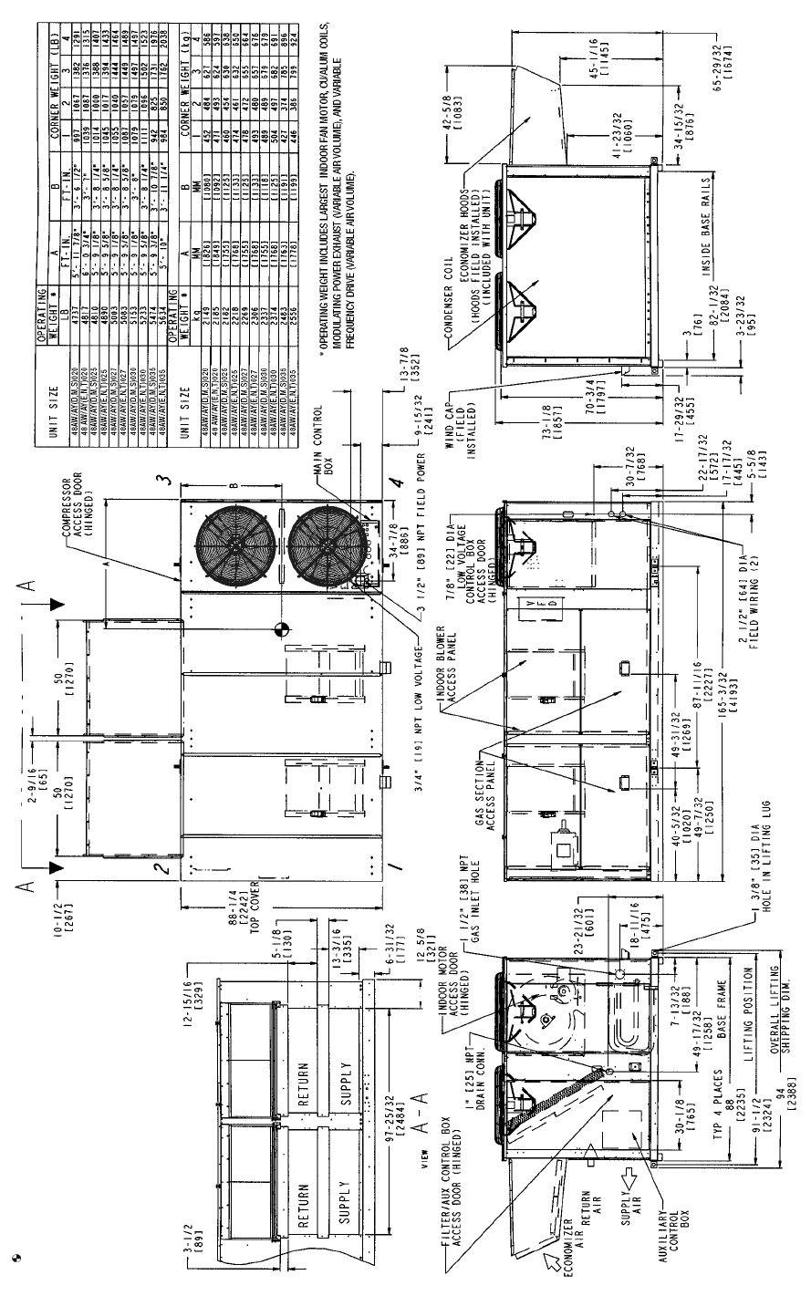
Fig. 8 — Base Unit Dimensions — 48AW,AY036-050
a48-8239
NOTES:
1. WEIGHTS INCLUDE ECONOMIZER (STD).
2. CENTER OF GRAVITY.
3. UNIT CLEARANCES:
TOP OF UNITS: NO OVERHANG
CONDENSER COIL: 4’ - 0“ [1219]
ECONOMIZER SIDE: 6’ - 0” [1829]
HEAT SIDE: 4’’ - 0” [1219]
FILTER ACCESS SIDE: 10’ - 0” [3048] (FOR REMOVAL
OF EVAPORATOR COIL)
4. FOR SMALLER SERVICE AND OPERATIONAL CLEAR-
ANCES, CONTACT CARRIER APPLICATION ENGINEER-
ING DEPARTMENT.
5. DIMENSIONS IN [ ] ARE IN MILLIMETERS. ALL OTHER DI-
MENSIONS ARE IN INCHES.
11
Fig. 9 — Base Unit Dimensions — 48AW,AY051 and 060
a48-8240
FOR CENTERS OF
GRAVITY, OPERATING
AND CORNER WEIGHTS,
SEE FIGURE 10
12
48AJ/AK LOW HEAT
48AJ/AK HIGH HEAT
48AJ/AK LOW HEAT
48AJ/AK HIGH HEAT
48AW/AY HIGH HEAT
48AW/AY LOW HEAT
48AW/AY LOW HEAT
48AW/AY HIGH HEAT
48AJ/AK051 LOW HEAT
48AJ/AK051 HIGH HEAT
48AW/AY051 LOW HEAT
48AW/AY051 HIGH HEAT
48AJ/AK060 LOW HEAT
48AW/AY060 LOW HEAT
48AJ/AK060 HIGH HEAT
48AW/AY060 HIGH HEAT
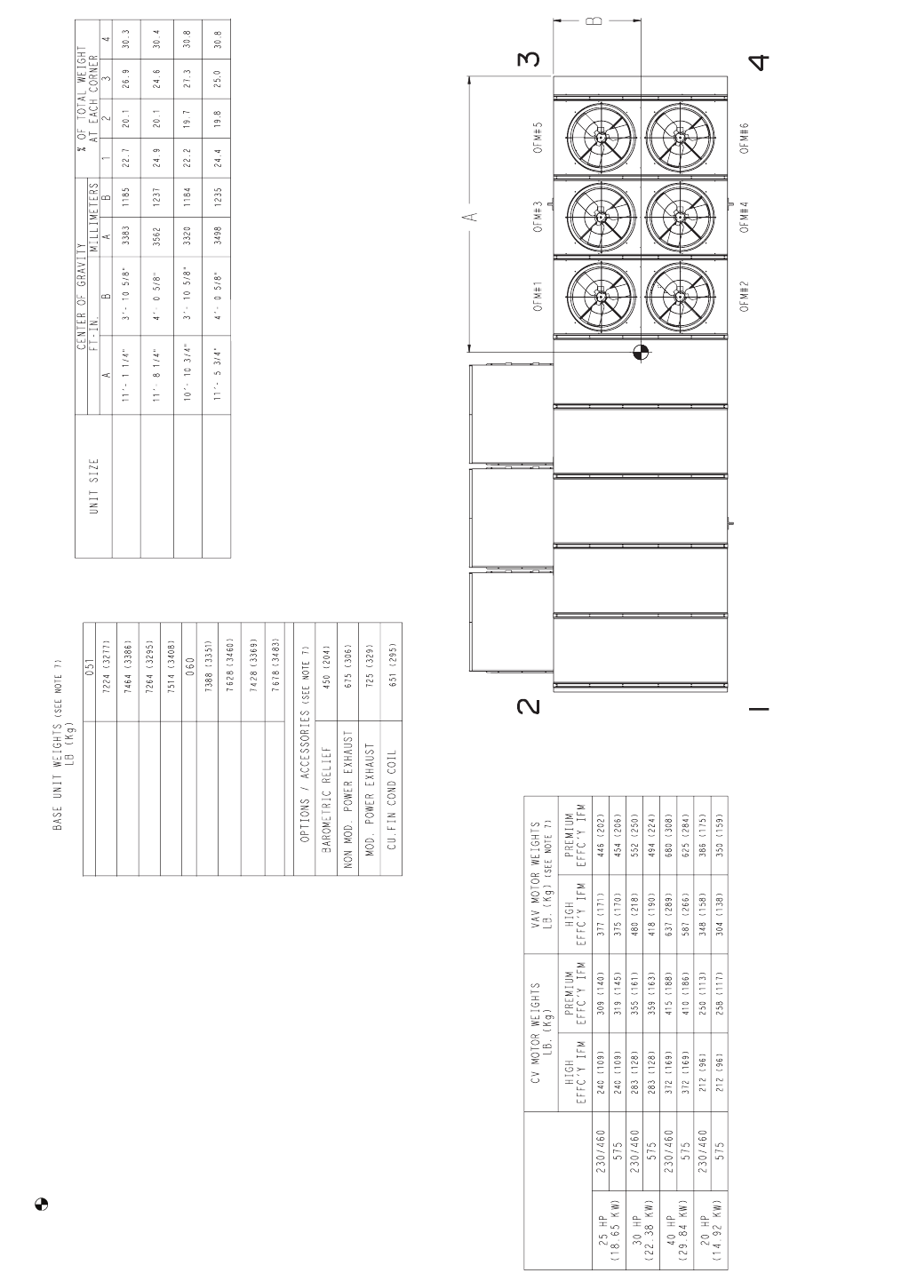
Fig. 10 — Center of Gravity and Weights — 48AJ,AK,AW,AY051,060
a50-8102
NOTES:
1. WEIGHTS INCLUDE ECONOMIZER OR OUTDOOR AIR
DAMPER.
2. CENTER OF GRAVITY.
3. UNIT CLEARANCES:
TOP OF UNITS: NO OVERHANG
CONDENSER COIL: 4’ - 0“ [1219]
ECONOMIZER SIDE: 6’ - 0” [1829]
HEAT SIDE: 4’’ - 0” [1219]
FILTER ACCESS SIDE: 15’ - 0” [4572] (FOR REMOVAL
OF EVAPORATOR COIL)
4. FOR SMALLER SERVICE AND OPERATIONAL CLEARANCES,
CONTACT CARRIER APPLICATION ENGINEERING DEPART-
MENT.
5. BOTTOM DUCTS ARE DESIGNED TO BE ATTACHED TO AC-
CESSORY ROOF CURB. IF UNIT IS MOUNTED ON DUNNAGE,
IT IS RECOMMENDED THAT THE DUCTS BE SUPPORTED BY
CROSS BRACES AS DONE ON ACCESSORY ROOF CURB.
6. BASE UNIT WEIGHTS INCLUDE OUTDOOR AIR HOODS AND
FILTERS (INDOOR FAN MOTOR IS NOT INCLUDED). ADD IN-
DOOR FAN MOTOR, FIOPS, AND ACCESSORIES FOR TOTAL
OPERATING WEIGHT.
7. VAV MOTOR WEIGHTS INCLUDE INDOOR MOTOR, VFD, VFD
TRANSDUCER, AND ASSOCIATED WIRING.
8. DIMENSIONS IN [ ] ARE IN MILLIMETERS. ALL OTHER DIMEN-
SIONS ARE IN INCHES.
9. FOR SIDE-SUPPLY/RETURN APPLICATIONS, A SINGLE RE-
TURN AND SUPPLY DUCTWORK CONNECTION IS RECOM-
MENDED FOR COVERING ALL THREE RETURN AND ALL
THREE SUPPLY OPENINGS. THE ENTIRE AREA AROUND
THE DUCT OPENINGS IS AVAILABLE FOR A 1.5” DUCT
FLANGE ATTACHMENT.
LEGEND
CV — Constant Volume
FIOP — Factory-Installed Option
IFM — Indoor Fan Motor
VAV — Volume Air volume
VFD — Variable Frequency Drive
13
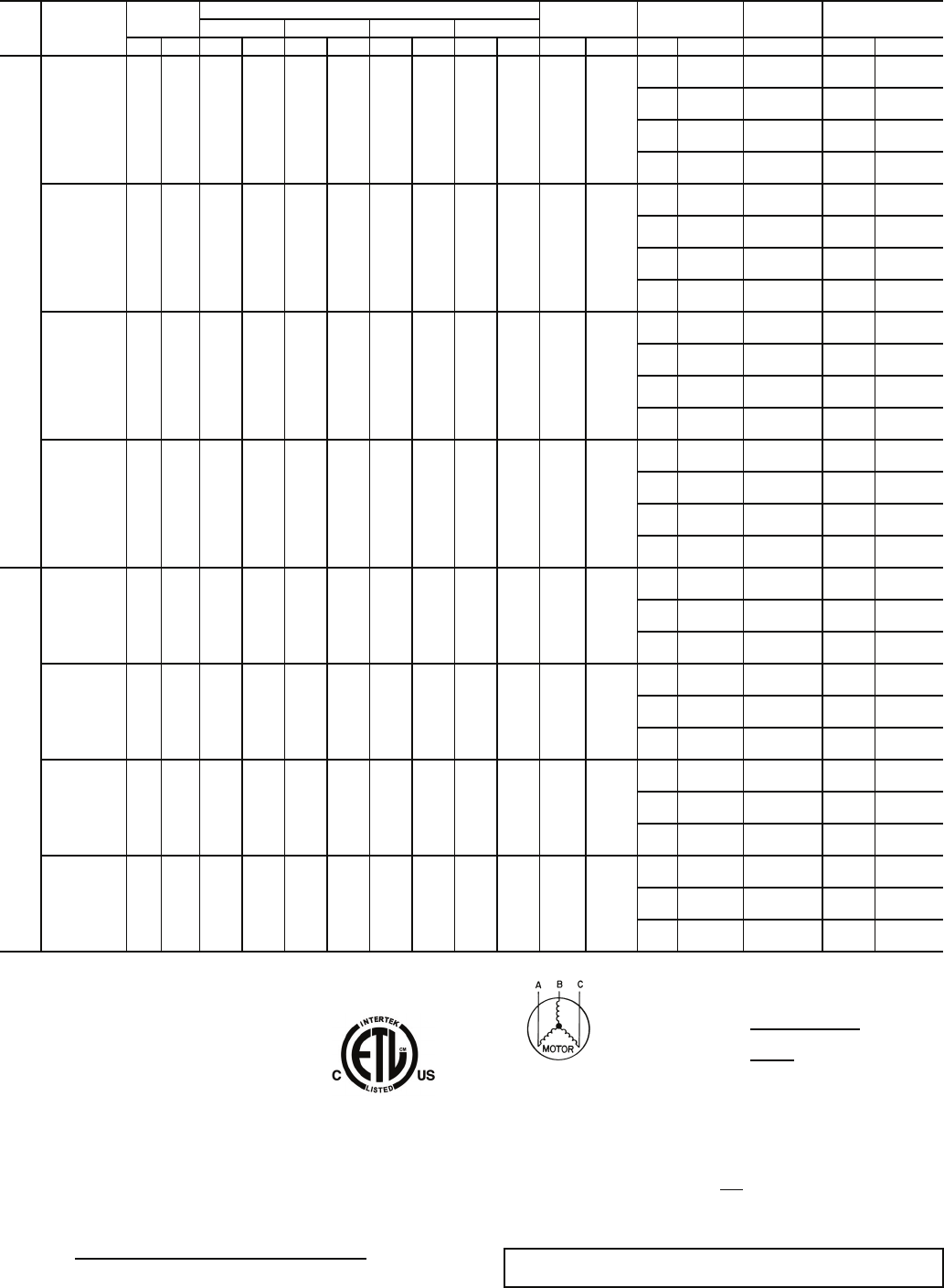
Table 1 — Physical Data — 48AJ,AK,AW,AY Units
LEGEND *Sizes 020-040: Circuit 1 uses the lower portion of condenser coil, Circuit 2 uses the upper
portion.
Sizes 041-060: Circuit 1 uses the left condenser coil, Circuit 2 the right. All units have
intertwined evaporator coils.
†Rollout switch is manual reset.
UNIT 48AJ,AK,AW,AY 020 025 027 030
NOMINAL CAPACITY (tons) 20 25 27 30
BASE UNIT See Operating Weights Table
OPERATING WEIGHT (lb)
COMPRESSOR
Quantity ... Type (Ckt 1/Ckt 2) 2…SR*782AT/1…SR*782AE 1…SR*812AT, 1…SR*942AT/
1…SR*942AE 2 ... SR*942AT/1…SR*942AE 2…SR*782AT/2…SR*812AT
Number of Refrigerant Circuits 22 22
Oil (oz) (Ckt 1, Ckt 2) Precharged Precharged Precharged Precharged
REFRIGERANT TYPE R-22
Operating Charge (lb-oz)
Circuit 1 26-8 33-8 35-8 29-0
Circuit 2 14-0 17-8 20-0 30-8
CONDENSER COIL* Internally Enhanced, 3/8
″ Copper Tubes, Aluminum Lanced, Aluminum Pre-Coated, or Copper Plate Fins
Quantity 11 11
Rows ... Fins/in. 2 ... 15 3 ... 15 3 ... 15 4 ... 15
Total Face Area (sq ft) 33.3 33.3 33.3 33.3
CONDENSER FAN Propeller Type
Nominal Cfm 17,200 15,850 15,850 14,500
Quantity... Diameter (in.) 2 ... 30 2 ... 30 2 ... 30 2 ... 30
Motor Hp 11 11
EVAPORATOR COIL Internally Enhanced Copper Tubes, Aluminum Plate Fins with Intertwined Circuits
Tube Size (in.) 3/83/83/83/8
Rows ... Fins/in. 3 ... 15 3 ... 15 4 ... 15 4 ... 15
Total Face Area (sq ft) 31.7 31.7 31.7 31.7
EVAPORATOR FAN Centrifugal Type
Quantity ... Size (in.) 2 ... 20 X 15 2 ... 20 X 15 2 ... 20 X 15 2 ... 20 X 15
Type Drive Belt Belt Belt Belt
Nominal Cfm 8,000 10,000 11,000 12,000
Motor Hp 5 10 15 5 10 15 10 15 20 10 15 20
Motor Frame Size 184T 215T 254T 184T 215T 254T 215T 254T 256T 215T 254T 256T
Motor Bearing Type Ball Ball Ball Ball
Maximum Allowable Rpm 1200 1200 1200 1200
Motor Pulley Pitch Diameter (in.) 4.8 4.4 5.7 4.8 6.1 5.5 4.4 4.9 5.9 4.4 5.7 5.9
Nominal Motor Shaft Diameter (in.) 11/813/815/811/813/815/813/815/815/813/815/815/8
Fan Pulley Pitch Diameter (in.) 12.4 8.6 9.1 12.4 11.1 8.7 9.4 8.1 8.7 9.5 9.1 8.7
Nominal Fan Shaft Diameter (in.) 115/16 115/16 115/16 115/16
Belt Quantity 112 1 1 2 2 22222
Belt Type BX56 BX50 5VX530 BX56 5VX570 5VX530 BX50 5VX530 5VX530 BX50 5VX530 5VX530
Belt Length (in.) 56 63 53 56 57 53 50 50 53 50 53 53
Pulley Center Line Distance (in.) 16.0-18.7 15.6-18.4 15.0-17.9 15.6-18.4 15.6-18.4 15.0-17.9 15.6-18.4 15.0-17.9 15.0-17.9 15.6-18.4 15.0-17.9 15.0-17.9
Factory Speed Setting (rpm) 677 895 1096 677 962 1106 819 1096 1187 884 1096 1187
FURNACE SECTION
Supply Line Pressure Range 5.0-in. wg min/13.5-in. wg max.
Rollout Switch Cutout
Temp (F)† 225 225 225 225
Burner Orifice Diameter (in. ...drill size)
Natural Gas Std .111 ... 34 .111 ... 34 .111 ... 34 .111 ... 34
Liquid Propane Alt .089 ... 43 .089 ... 43 .089 ... 43 .089 ... 43
Thermostat Heat Anticipator Setting
Stage 1 (amps) 0.24 0.24 0.24 0.24
Stage 2 (amps) 0.13 0.13 0.13 0.13
Gas Input (Btuh) Stage 1
(Low Heat/High Heat) 262,500/394,000 262,500/394,000 262,500/394,000 262,500/394,000
Stage 2
(Low Heat/High Heat) 350,000/525,000 350,000/525,000 350,000/525,000 350,000/525,000
Efficiency (Steady State) (%) 82 82 82 82
Temperature Rise Range 15-45/35-65 15-45/35-65 15-45/35-65 15-45/35-65
Manifold Pressure (in. wg)
Natural Gas Std 3.5 3.5 3.5 3.5
Liquid Propane Alt 3.5 3.5 3.5 3.5
Gas Valve Quantity 22 22
HIGH-PRESSURE SWITCH (psig)
Cutout 426 426 426 426
Reset (Auto.) 320 320 320 320
MIXED-AIR FILTERS
Quantity ... Size (in.) Standard 10 ... 20 x 24 x 2 10 ... 20 x 24 x 2 10 ... 20 x 24 x 2 10 ... 20 x 24 x 2
Pleated 5 ... 20 x 20 x 4
5 ... 20 x 24 x 4
5 ... 20 x 20 x 4
5 ... 20 x 24 x 4
5 ... 20 x 20 x 4
5 ... 20 x 24 x 4
5 ... 20 x 20 x 4
5 ... 20 x 24 x 4
OUTDOOR-AIR FILTERS
Quantity...Size (in.) 8...16 x 25 x 2
4...20 x 25 x 2
POWER EXHAUST Direct Drive, Single-Phase Motors (Factory-Wired for High Speed Operation), Forward-Curved Fan Wheels with Backdraft Dampers on Each Fan
Housing
Motor, Quantity...Hp 4...1
Fan, Diameter...Width (in.) 11 x 10
Al — Aluminum
Cu — Copper

14
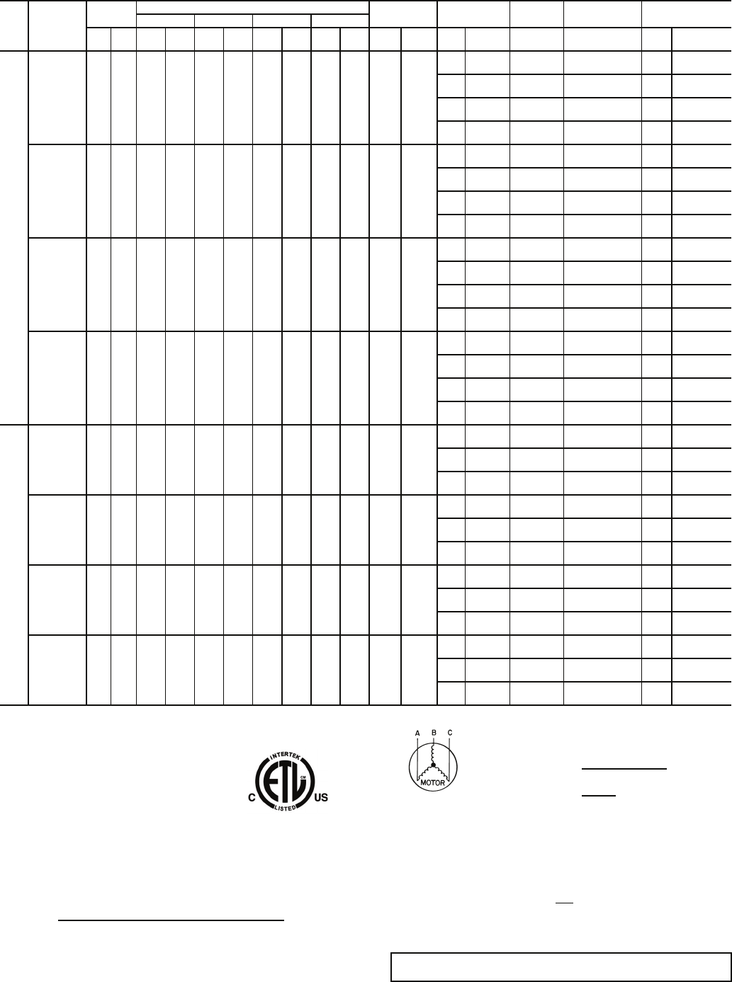
Table 1 — Physical Data — 48AJ,AK,AW,AY Units (cont)
LEGEND *Sizes 020-040: Circuit 1 uses the lower portion of condenser coil, Circuit 2 uses the upper
portion.
Sizes 041-060: Circuit 1 uses the left condenser coil, Circuit 2 the right. All units have
intertwined evaporator coils.
†Rollout switch is manual reset.
UNIT 48AJ,AK,AW,AY 035 036 040 041
NOMINAL CAPACITY (tons) 35 35 40 40
BASE UNIT See Operating Weights Table
OPERATING WEIGHT (lb)
COMPRESSOR
Quantity ... Type (Ckt 1/Ckt 2) 1…SR*812AT,
1…SR*942AT/2…SR*942AT
1…SR*812AT,
1…SR*942AT/2…SR*942AT 2…SR*942AT/2…SM125 2…SR*942AT/2…SM125
Number of Refrigerant Circuits 2222
Oil (oz) (Ckt 1, Ckt 2) Precharged Precharged Precharged Precharged
REFRIGERANT TYPE R-22
Operating Charge (lb-oz)
Circuit 1 33-0 36-0 36-0 47-0
Circuit 2 38-0 58-0 47-0 47-0
CONDENSER COIL* Internally Enhanced, 3/8
″ Copper Tubes, Aluminum Lanced, Aluminum Pre-Coated, or Copper Plate Fins
Quantity 1222
Rows ... Fins/in. 4 ... 15 2...15/4…15 2 ... 15 / 4 … 15 4...15/4…15
Total Face Area (sq ft) 33.3 66.7 66.7 66.7
CONDENSER FAN Propeller Type
Nominal Cfm 14,500 30,000 30,000 30,000
Quantity... Diameter (in.) 2 ... 30 4...30 4 ... 30 4...30
Motor Hp 1111
EVAPORATOR COIL Internally Enhanced Copper Tubes, Aluminum Plate Fins with Intertwined Circuits
Tube Size (in.) 1/21/21/21/2
Rows ... Fins/in. 6 ... 16 4...17 4 ... 16 4...17
Total Face Area (sq ft) 31.3 31.3 31.3 31.3
EVAPORATOR FAN Centrifugal Type
Quantity ... Size (in.) 2 ... 20 X 15 2...20 X 15 2 ... 20 X 15 2...20 X 15
Type Drive Belt Belt Belt Belt
Nominal Cfm 14,000 14,000 16,000 16,000
Motor Hp 15 20 25 15 20 25 15 20 25 15 20 25
Motor Frame Size 254T 256T 284T 254T 256T 284T 254T 256T 284T 254T 256T 284T
Motor Bearing Type Ball Ball Ball Ball
Maximum Allowable Rpm 1300 1300 1300 1300
Motor Pulley Pitch Diameter (in.) 5.15.76.25.35.77.55.35.77.55.35.77.5
Nominal Motor Shaft Diameter (in.) 15/815/817/815/815/817/815/815/817/815/815/817/8
Fan Pulley Pitch Diameter (in.) 8.7 8.7 8.7 9.5 9.5 11.1 9.5 9.5 11.1 9.5 9.5 11.1
Nominal Fan Shaft Diameter (in.) 115/16 115/16 115/16 115/16
Belt Quantity 222222222222
Belt Type 5VX500 5VX530 5VX550 5VX530 5VX550 5VX590 5VX530 5VX550 5VX590 5VX530 5VX550 5VX590
Belt Length (in.) 50 53 55 53 55 59 53 55 59 53 55 59
Pulley Center Line Distance (in.) 15.0-17.9 15.0-17.9 15.0-17.9 15.0-17.9 15.0-17.9 14.6-17.6 15.0-17.9 15.0-17.9 14.6-17.6 15.0-17.9 15.0-17.9 14.6-17.6
Factory Speed Setting (rpm) 1005 1147 1247 976 1050 1182 976 1050 1182 976 1050 1182
FURNACE SECTION
Supply Line Pressure Range 5.0-in. wg min/13.5-in. wg max.
Rollout Switch Cutout
Temp (F)† 225 225 225 225
Burner Orifice Diameter (in ...drill size)
Natural Gas Std .111 ... 34 .120...31 .120 ... 31 .120...31
Liquid Propane Alt .089 ... 43 .096...41 .096 ... 41 .096...41
Thermostat Heat Anticipator Setting
Stage 1 (amps) 0.24 0.1 0.24 0.1
Stage 2 (amps) 0.13 0.1 0.13 0.1
Gas Input (Btuh) Stage 1
(Low Heat/High Heat) 262,500/394,000 300,000/600,000 300,000/600,000 300,000/600,000
Stage 2
(Low Heat/High Heat) 350,000/525,000 400,000/800,000 400,000/800,000 400,000/800,000
Efficiency (Steady State) (%) 82 82 82 82
Temperature Rise Range 15-45/35-65 10-40/30-60 10-40/3 -60 10-40/30-60
Manifold Pressure (in. wg)
Natural Gas Std 3.5 3.5 3.5 3.5
Liquid Propane Alt 3.5 3.5 3.5 3.5
Gas Valve Quantity 2222
HIGH-PRESSURE SWITCH (psig)
Cutout 426 426 426 426
Reset (Auto.) 320 320 320 320
MIXED-AIR FILTERS
Quantity ... Size (in.) Standard 10 ... 20 x 24 x 2 10...20 x 24 x 2
5...20 x 20 x 4
5...20 x 20 x 4
10 ... 20 x 24 x 2 10...20 x 24 x 2
5...20 x 20 x 4
5...20 x 20 x 4
Pleated 5 ... 20 x 20 x 4
5 ... 20 x 24 x 4
5 ... 20 x 20 x 4
5 ... 20 x 24 x 4
OUTDOOR-AIR FILTERS
Quantity...Size (in.) 8...16 x 25 x 2
4...20 x 25 x 2
POWER EXHAUST Direct Drive, Single-Phase Motors (Factory-Wired for High Speed Operation), Forward-Curved Fan Wheels with Backdraft Dampers on Each Fan Housing
Motor, Quantity...Hp 4...1
Fan, Diameter...Width (in.) 11 x 10
Al — Aluminum
Cu — Copper
15
Table 1 — Physical Data — 48AJ,AK,AW,AY Units (cont)
LEGEND *Sizes 020-040: Circuit 1 uses the lower portion of condenser coil, Circuit 2 uses the upper
portion.
Sizes 041-060: Circuit 1 uses the left condenser coil, Circuit 2 the right. All units have
intertwined evaporator coils.
†Rollout switch is manual reset.
UNIT 48AJ,AK,AW,AY 050 051 060
NOMINAL CAPACITY (tons) 50 50 60
BASE UNIT See Operating Weights Table
OPERATING WEIGHT (lb)
COMPRESSOR
Quantity ... Type (Ckt 1/Ckt 2) 2…SM125/1…SM125,
1…SM175 2…SM125/2…SM125 1..SM160,1..SM175/
1..SM160,1..SM175
Number of Refrigerant Circuits 22 2
Oil (oz) (Ckt 1, Ckt 2) Precharged Precharged Precharged
REFRIGERANT TYPE R-22
Operating Charge (lb-oz)
Circuit 1 64-4 98-0 81-0
Circuit 2 58-8 98-0 81-0
CONDENSER COIL* Internally Enhanced, 3/8
″ Copper Tubes, Aluminum Lanced, Aluminum Pre-Coated, or Copper Plate Fins
Quantity 22 2
Rows ... Fins/in. 4 ... 15 4…15 4…15
Total Face Area (sq ft) 66.7 100 100
CONDENSER FAN Propeller Type
Nominal Cfm 25,600 38,400 38,400
Quantity... Diameter (in.) 4 ... 30 6...30 6 ... 30
Motor Hp 11 1
EVAPORATOR COIL Internally Enhanced Copper Tubes, Aluminum Plate Fins with Intertwined Circuits
Tube Size (in.) 1/21/21/2
Rows ... Fins/in. 6 ... 16 4...17 4 ... 17
Total Face Area (sq ft) 31.3 48.1 48.1
EVAPORATOR FAN Centrifugal Type
Quantity ... Size (in.) 2 ... 20 X 15 3...20 X 15 3 ... 20 X 15
Type Drive Belt Belt Belt
Nominal Cfm 20,000 20,000 24,000
Motor Hp 20 25 30 20 25 30 40
(High Eff.)
40
(Prem. Eff.) 25 30 40
(High Eff.)
40
(Prem. Eff.)
Motor Frame Size 256T 284T 286T 256T 284T 286T 324T 324T 284T 286T 324T 324T
Motor Bearing Type Ball Ball Ball
Maximum Allowable Rpm 1300 1200 1200
Motor Pulley Pitch Diameter (in.) 5.7 6.2 6.7 5.9 5.3 5.9 6.5 9.5 5.3 5.9 6.5 9.5
Nominal Motor Shaft Diameter (in.) 15/817/817/815/817/817/821/821/817/817/821/821/8
Fan Pulley Pitch Diameter (in.) 9.5 9.5 9.5 11.1 9.1 9.5 9.5 13.7 9.1 9.5 9.5 13.7
Nominal Fan Shaft Diameter (in.) 115/16 115/16 115/16
Belt Quantity 2222333 2 333 2
Belt Type 5VX550 5VX570 5VX570 5VX560 5VX530 5VX550 5VX570 5VX650 5VX530 5VX550 5VX570 5VX650
Belt Length (in.) 55 57 57 56 53 55 57 65 53 55 57 65
Pulley Center Line Distance (in.) 15.0-17.9 14.6-17.6 14.6-17.6 15.0-17.9 15.2-17.5 14.7-17.2 14.2-17.0 14.2-17.0 15.2-17.5 14.7-17.2 14.2-17.0 14.2-17.0
Factory Speed Setting (rpm) 1061 1154 1249 930 1019 1086 1197 1214 1019 1086 1197 1214
FURNACE SECTION
Supply Line Pressure Range 5.0-in. wg min/13.5-in. wg max.
Rollout Switch Cutout
Temp (F)† 225 225 225
Burner Orifice Diameter (in ...drill size)
Natural Gas Std .120 ... 31 .120...31 .120 ... 31
Liquid Propane Alt .096 ... 41 .096...41 .096 ... 41
Thermostat Heat Anticipator Setting
Stage 1 (amps) 0.24 0.1 0.36
Stage 2 (amps) 0.13 0.1 0.13
Gas Input (Btuh) Stage 1
(Low Heat/High Heat) 300,000/600,000 582,000/873,000 582,000/873,000
Stage 2
(Low Heat/High Heat) 400,000/800,000 776,000/1,164,000 776,000/1,164,000
Efficiency (Steady State) (%) 82 82 82
Temperature Rise Range 10-40/30-60 10-40/30-60 10-40/30-60
Manifold Pressure (in. wg)
Natural Gas Std 3.5 3.3 3.3
Liquid Propane Alt 3.5 3.3 3.3
Gas Valve Quantity 23 3
HIGH-PRESSURE SWITCH (psig)
Cutout 426 426 426
Reset (Auto.) 320 320 320
MIXED-AIR FILTERS
Quantity ... Size (in.) Standard 10 ... 20 x 24 x 2 16...20 x 24 x 2
8...20 x 20 x 4
8...20 x 24 x 4
16 ... 20 x 24 x 2
Pleated 5 ... 20 x 20 x 4
5 ... 20 x 24 x 4
8 ... 20 x 20 x 4
8 ... 20 x 24 x 4
OUTDOOR-AIR FILTERS
Quantity...Size (in.) 8...16 x 25 x 2
4...20 x 25 x 2
12...16 x 25 x 2
6...20 x 25 x 2
POWER EXHAUST Direct Drive, Single-Phase Motors (Factory-Wired for High Speed Operation), Forward-Curved Fan Wheels with Backdraft Dampers on Each Fan Housing
Motor, Quantity...Hp 4...1
11 x 10
6...1
11 x 10 Fan, Diameter...Width (in.)
Al — Aluminum
Cu — Copper
16
50AJ/AK020 4607 2090 87.7 2227 70.9 1801 42.0 1067
48AJ/AKD020 4697 213187.7 2227 71.9 1826 42.5 1080
48AJ/AKE020 4777 2167 87.7 2227 72.8 1849 41.0 1041
50AW/AY020 4685 2125 87.7 2227 70.9 1801 42.0 1067
48AW/AYD020 4737 2149 87.7 2227 71.9 1826 42.5 1080
48AW/AYE020 4817 2185 87.7 2227 72.8 1849 41.0 1041
50AJ/AK025 4680 212387.7 2227 68.0 1727 43.9 1115
48AJ/AKD025 4770 2164 87.7 2227 69.1 1755 44.31125
48AJ/AKE025 4850 2200 87.7 2227 69.6 176844.6 1133
50AW/AY025 4758 215887.7 2227 68.0 1727 43.9 1115
48AW/AYD025 4810 2182 87.7 2227 69.1 1755 44.31125
48AW/AYE025 4890 221887.7 2227 69.6 176844.6 1133
50AJ/AK027 4873 2210 87.7 2227 68.0 1727 43.9 1115
48AJ/AKD027 4963 2251 87.7 2227 69.1 1755 44.31125
48AJ/AKE027 5043 228787.7 2227 69.6 176844.6 1133
50AW/AY027 4951 2246 87.7 2227 68.0 1727 43.9 1115
48AW/AYD027 50032269 87.7 2227 69.1 1755 44.31125
48AW/AYE027 5083 2306 87.7 2227 69.6 176844.6 1133
50AJ/AK030 5023 227887.7 2227 68.0 1727 43.6 1107
48AJ/AKD030 5113 2319 87.7 2227 69.1 1755 44.0 1118
48AJ/AKE030 5193 2356 87.7 2227 69.6 176844.31125
50AW/AY030 5101 2314 87.7 2227 68.0 1727 43.6 1107
48AW/AYD030 51532337 87.7 2227 69.1 1755 44.0 1118
48AW/AYE030 5233 2374 87.7 2227 69.6 176844.31125
50AJ/AK035 5229 2372 87.7 2227 68.3 173546.5 1181
48AJ/AKD035 5434 2465 87.7 2227 69.4 176346.9 1191
48AJ/AKE035 5594 2537 87.7 2227 70.0 177847.2 1199
50AW/AY035 5422 2459 87.7 2227 68.3 173546.5 1181
48AW/AYD035 5474 2483 87.7 2227 69.4 176346.9 1191
48AW/AYE0355634 2556 87.7 2227 70.0 177847.2 1199
50AJ/AK036 5609 2544 87.7 2227 93.4 2372 45.3 1152
48AJ/AKD036 5814 263787.7 2227 94.8 2409 45.8 1163
48AJ/AKE036 5974 2710 87.7 2227 96.3 2446 46.1 1172
50AW/AY0365802 263287.7 2227 93.3 2370 45.4 1153
48AW/AYD036 5854 2655 87.7 2227 94.8 240845.8 1163
48AW/AYE036 6014 272887.7 2227 96.3 2446 46.1 1172
50AJ/AK040 5769 2617 87.7 2227 90.8 2306 46.5 1181
48AJ/AKD040 5974 2710 87.7 2227 92.3 2344 46.9 1191
48AJ/AKE040 6134 278287.7 2227 93.8 2383 47.2 1199
50AW/AY040 5962 2704 87.7 2227 90.8 2306 46.5 1181
48AW/AYD040 6014 2728 87.7 2227 92.3 2344 46.9 1191
48AW/AYE040 6174 2801 87.7 2227 93.8 2383 47.2 1199
50AJ/AK041 5885 2669 87.7 2227 89.0 2261 45.6 1158
48AJ/AKD041 6090 2762 87.7 2227 90.5 2300 46.0 1169
48AJ/AKE041 6250 283587.7 2227 92.1 2338 46.3 1177
50AW/AY041 6078 2757 87.7 2227 89.1 2262 45.6 1159
48AW/AYD041 61302781 87.7 2227 90.6 2300 46.0 1169
48AW/AYE041 6290 285387.7 2227 92.1 233946.3 1177
50AJ/AK050 6338 2875 87.7 2227 89.2 2266 46.1 1171
48AJ/AKD050 6543 296887.7 2227 90.7 2304 46.5 1181
48AJ/AKE050 6703 3040 87.7 2227 92.2 2342 46.8 1189
50AW/AY050 6531 2962 87.7 2227 89.2 2266 46.1 1171
48AW/AYD050 6583 2986 87.7 2227 90.7 2304 46.5 1181
48AW/AYE050 67433059 87.7 2227 92.2 2342 46.8 1189
50AJ/AK051 8544 3876 161.7 4106 126.0 3200 44.6 1133
48AJ/AKD051 8674 3935 161.7 4106 133.2 3383 46.6 1185
48AJ/AKE051 8914 4043161.7 4106 140.2 3562 48.7 1237
50AW/AY051 8759 3973161.7 4106 125.9 319844.6 1133
48AW/AYD051 8714 3953 161.7 4106 133.2 3382 46.6 1185
48AW/AYE051 8964 4066 161.7 4106 140.2 3562 48.7 1237
50AJ/AK060 8708 3950 161.7 4106 123.6 3139 44.6 1133
48AJ/AKD060 8838 4009 161.7 4106 130.7 3320 46.6 1184
48AJ/AKE060 9078 4118161.7 4106 137.7 349848.6 1234
50AW/AY060 89234047 161.7 4106 123.6 3139 44.6 1133
48AW/AYD060 88784027 161.7 4106 130.7 3320 46.6 1184
48AW/AYE060 91284140 161.7 4106 137.7 3498 48.6 1234
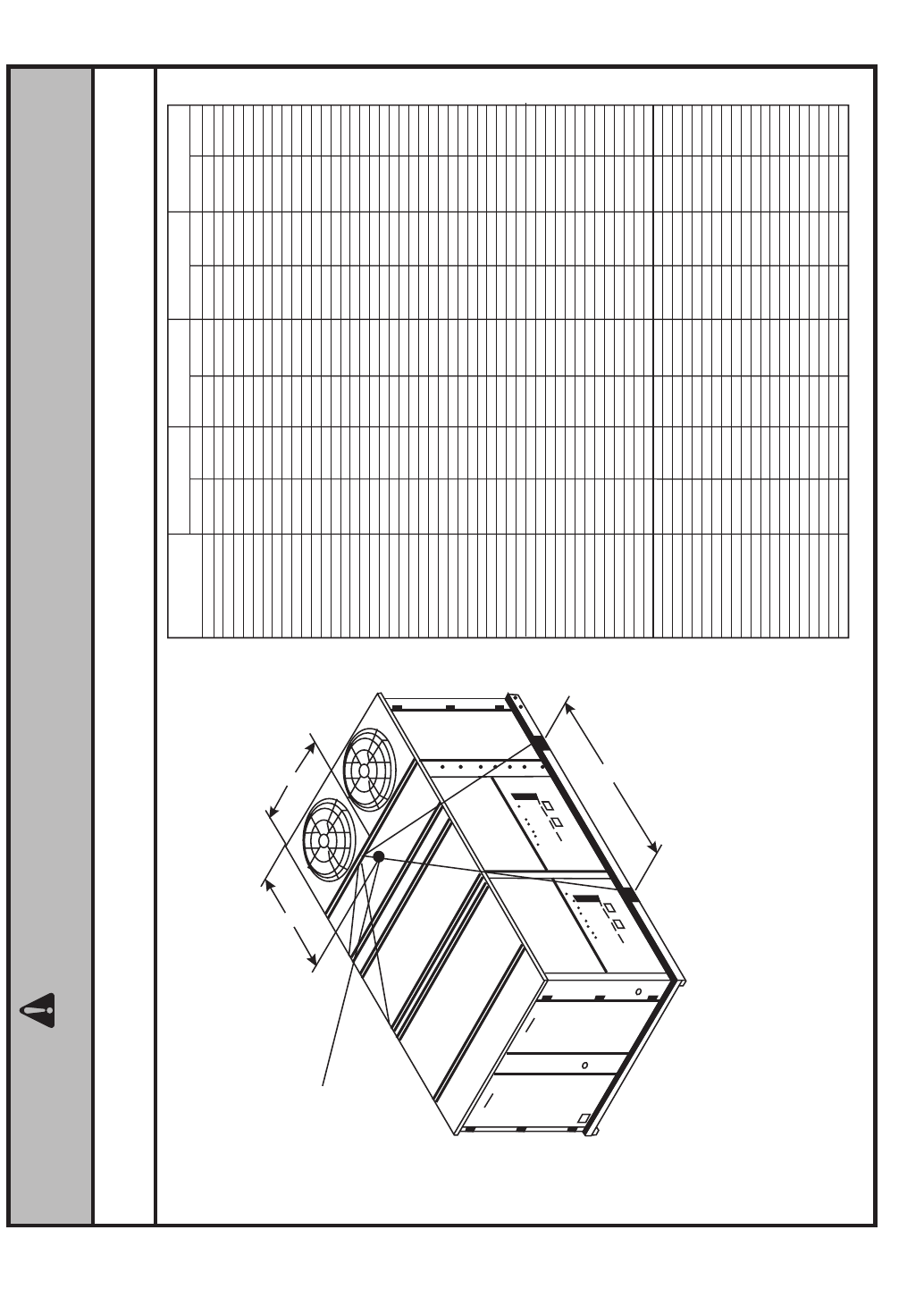
NOTE: Rig with four cables and spread with two 92 inch (2337 MM) spreader bars.
Maintain a distance of 74 inches (1880 MM) from top of unit to eyehook.
CAUTION - NOTICE TO RIGGERS:
ALL PANELS MUST BE IN PLACE WHEN RIGGING.
CENTER
OF
GRAVITY
WEIGHT BAC
LB KG INCHESMM INCHESMM INCHESMM
B
A
C
NOTE:
Add 312 lb (142 kg) for export crating. (020-035 units)
Add 346 lb (157 kg) for export crating. (036-050 units)
Add 588 lb (266 kg) for export crating. (051 and 060 units)
Add 220 lb (100 kg) for copper condenser coil. (020-035 units)
Add 380 lb (172 kg) for copper condenser coil. (036-050 units)
Add 651 lb (295 kg) for copper condenser coil. (051 and 060 units)
UNIT
Fig. 11 — Rigging Information
a48-8246
17
Table 2 — Unit Operating Weights
Table 3 — Option and Accessory Weights
Table 4 — Constant Volume Fan Motor Weights
LEGEND
Table 5 — Variable Volume Fan Motor Weights
NOTES:
1. Base unit weight includes outdoor-air hoods. Base unit weight
does NOT include indoor-fan motor. ADD indoor-fan motor,
FIOPs, and accessories for TOTAL operating weight.
2. The VAV motor weights include indoor fan motor and the VFD
(variable frequency drive), VFD transducers, and associated
wiring.
UNIT BASE UNIT WEIGHTS — lb
020 025 027 030 035 036 040 041 050 051 060
48AJ/AK Low Heat 3842 3915 4032 4182 4435 4815 4975 5091 5446 7224 7388
48AJ/AK High Heat 3922 3995 4112 4262 4595 4975 5135 5251 5606 7464 7628
48AW/AY Low Heat 3882 3955 4072 4222 4475 4855 5015 5131 5486 7264 7428
48AW/AY High Heat 3962 4035 4152 4302 4635 5015 5175 5291 5646 7514 7678
OPTION/
ACCESSORY
OPTION/ACCESSORY WEIGHTS — lb
020 025 027 030 035 036 040 041 050 051 060
Barometric Relief 300 300 300 300 300 300 300 300 300 450 450
Power Exhaust 450 450 450 450 450 450 450 450 450 675 675
Mod. Power Exhaust 500 500 500 500 500 500 500 500 500 725 725
Cu Tubing/Cu Fin Condenser Coil 220 220 220 220 285 380 285 380 380 651 651
Outdoor Air Hood Crate and Packaging
(Less Hoods' Weight)
45 45 45 45 45 45 45 45 45 45 45
(Packaging Only) (Packaging Only)
Outdoor Air Hoods/Filters 170 170 170 170 170 170 170 170 170 255 255
Hail Guard 73 73 73 73 73 146 146 146 146 219 219
Roof Curb (14-in.) 365 365 365 365 410 410 410 410 410 540 585
CV MOTOR WEIGHTS — lb
MOTOR
HP
UNIT
VOLTAGE
HIGH
EFFICIENCY
IFM
PREMIUM
EFFICIENCY
IFM
5230/460 78 94
575 78 92
10 230/460 118 164
575 118 156
15 230/460 150 217
575 150 220
20 230/460 212 250
575 212 258
25 230/460 240 309
575 240 319
30 230/460 283 355
575 283 359
40 230/460 372 415
575 372 410
Cu — Copper
CV — Constant Volume
FIOP — Factory-Installed Option
HP — Horsepower
IFM — Indoor Fan Motor
VAV — Variable Air Volume
VFD — Variable Frequency Drive
VAV MOTOR WEIGHTS — lb
MOTOR
HP
UNIT
VOLTAGE
HIGH
EFFICIENCY
IFM
PREMIUM
EFFICIENCY
IFM
5230/460 125 141
575 163 177
10 230/460 204 250
575 204 242
15 230/460 238 305
575 240 310
20 230/460 348 386
575 304 350
25 230/460 377 446
575 375 454
30 230/460 480 552
575 418 494
40 230/460 637 680
575 587 625
LEGEND AND NOTES FOR TABLES 2-5

18
Table 6 — Evaporator Fan Motor Data
NOTES:
1. Motor shaft speed is 1750 rpm. The fan shaft diameter is 115/16 inches.
2. All indoor fan motors meet the minimum efficiency requirements
as established by the Energy Policy Act of 1992 (EPACT), effective
October 24, 1997.
UNIT
SIZE
48AJ,AK,
AW,AY
MOTOR
HP
MOTOR
SHAFT DIA.
(in.)
FAN
SHAFT
SPEED
(rpm)
MOTOR
SHEAVE
(P/N)
MOTOR
SHEAVE
PITCH
DIAMETER
(in.)
BUSHING
DIAMETER
(in.)
FAN
SHEAVE
(P/N)
FAN
SHEAVE
PITCH
DIAMETER
(in.)
BUSHING
DIAMETER
(in.)
BELT
(Quantity)
(P/N)
BELT
TENSION
(lb at .25 in.)
020
5 1.125 677 BK55 4.8 NONE - 1.125 1B5V124 12.4 B - 1.9375 BX56 8
10 1.375 895 2BK50 4.4 NONE - 1.375 2B5V86 8.6 B - 1.9375 BX50 8
15 1.625 1096 2B5V56 5.7 B - 1.625 2B5V90 9.1 B - 1.9375 (2) 5VX530 9
025
5 1.125 677 BK55 4.8 NONE - 1.125 1B5V124 12.4 B - 1.9375 BX56 8
10 1.375 962 1B5V60 6.1 H - 1.375 1B5V110 11.1 B - 1.9375 5VX570 11
15 1.625 1106 2B5V54 5.5 B - 1.625 2B5V86 8.7 B - 1.9375 (2) 5VX530 9
027
10 1.375 819 2BK50 4.4 NONE - 1.375 2B5V94 9.4 B - 1.9375 (2) BX50 8
15 1.625 1096 2B5V56 5.7 B - 1.625 2B5V90 9.1 B - 1.9375 (2) 5VX530 10
20 1.625 1187 2B5V58 5.9 B - 1.625 2B5V86 8.7 B - 1.9375 (2) 5VX530 11
030
10 1.375 884 2BK50 4.4 H - 1.375 2B5V94 9.5 B - 1.9375 (2) BX50 8
15 1.625 1096 2B5V56 5.7 B - 1.625 2B5V90 9.1 B - 1.9375 (2) 5VX530 9
20 1.625 1187 2B5V58 5.9 B - 1.625 2B5V86 8.7 B - 1.9375 (2) 5VX530 11
035
15 1.625 1005 2B5V50 5.1 B - 1.625 2B5V86 8.7 B - 1.9375 (2) 5VX500 9
20 1.625 1147 2B5V56 5.7 B - 1.625 2B5V86 8.7 B - 1.9375 (2) 5VX530 10
25 1.875 1247 2B5V62 6.2 B - 1.875 2B5V86 8.7 B - 1.9375 (2) 5VX530 11
036
15 1.625 976 2B5V52 5.3 B - 1.625 2B5V94 9.5 B - 1.9375 (2) 5VX530 10
20 1.625 1050 2B5V56 5.7 B - 1.625 2B5V94 9.5 B - 1.9375 (2) 5VX550 11
25 1.875 1182 2B5V74 7.5 B - 1.875 2B5V110 11.1 B - 1.9375 (2) 5VX590 11
040
15 1.625 976 2B5V52 5.3 B - 1.625 2B5V94 9.5 B - 1.9375 (2) 5VX530 10
20 1.625 1050 2B5V56 5.7 B - 1.625 2B5V94 9.5 B - 1.9375 (2) 5VX550 11
25 1.875 1182 2B5V74 7.5 B - 1.875 2B5V110 11.1 B - 1.9375 (2) 5VX590 11
041
15 1.625 976 2B5V52 5.3 B - 1.625 2B5V94 9.5 B - 1.9375 (2) 5VX530 10
20 1.625 1050 2B5V56 5.7 B - 1.625 2B5V94 9.5 B - 1.9375 (2) 5VX550 11
25 1.875 1182 2B5V74 7.5 B - 1.875 2B5V110 11.1 B - 1.9375 (2) 5VX590 11
050
20 1.625 1061 2B5V56 5.7 B - 1.625 2B5V94 9.5 B - 1.9375 (2) 5VX550 10
25 1.875 1154 2B5V62 6.2 B - 1.875 2B5V94 9.5 B - 1.9375 (2) 5VX570 11
30 1.875 1247 2B5V66 6.7 B - 1.875 2B5V94 9.5 B - 1.9375 (2) 5VX570 13
051
20 1.625 930 2B5V58 5.9 B - 1.625 2B5V110 11.1 B - 1.9375 (2) 5VX560 11
25 1.875 1019 3B5V52 5.3 B - 1.875 3B5V90 9.1 B - 1.9375 (3) 5VX530 12
30 1.875 1086 3B5V58 5.9 B - 1.875 3B5V94 9.5 B - 1.9375 (3) 5VX550 12
40 High 2.125 1197 3B5V64 6.5 B - 2.125 3B5V94 9.5 B - 1.9375 (3) 5VX570 14
40 Prem. 2.125 1214 2B5V94 9.5 B - 2.125 2B5V136 13.7 B - 1.9375 (2) 5VX650 15
060
25 1.875 1019 3B5V52 5.3 B - 1.875 3B5V90 9.1 B - 1.9375 (3) 5VX530 12
30 1.875 1086 3B5V58 5.9 B - 1.875 3B5V94 9.5 B - 1.9375 (3) 5VX550 12
40 High 2.125 1197 3B5V64 6.5 B - 2.125 3B5V94 9.5 B - 1.9375 (3) 5VX570 14
40 Prem. 2.125 1214 2B5V94 9.5 B - 2.125 2B5V136 13.7 B - 1.9375 (2) 5VX650 15
Fig. 12 — Air Distribution — Thru-the-Bottom Fig. 13 — Air Distribution — Thru-the-Side
a48-8241 a48-8242
19
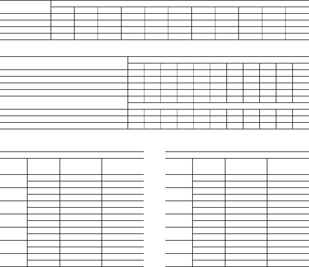
Step 5 — Install Flue Hood
48AJ,AK,AW,AY020-050 UNITS — Flue hood is shipped
inside gas section of unit. To install, secure flue hood to access
panel. See Fig. 14.
48AJ,AK,AW,AY051 AND 060 UNITS — Flue hood and
wind baffle are shipped inside gas section of unit. To install, se-
cure flue hood to access panel. Install the two pieces of the
wind baffle over the flue hood. See Fig. 15.
NOTE: When properly installed, flue hood will line up with
combustion fan housing. See Fig. 16.
Step 6 — Trap Condensate Drain — See Fig. 4-9
for drain location. Condensate drain is open to atmosphere and
must be trapped. Install a trapped drain at the drain location.
One 1-in. FPT coupling is provided inside the unit evaporator
section for condensate drain connection. A trap at least 4-in.
deep must be used. See Fig. 17. Trap must be installed to pre-
vent freeze-up.
Condensate pans are sloped so that water will completely
drain from the condensate pan to comply with indoor air quali-
ty guidelines. The condensate drain pans are not insulated.
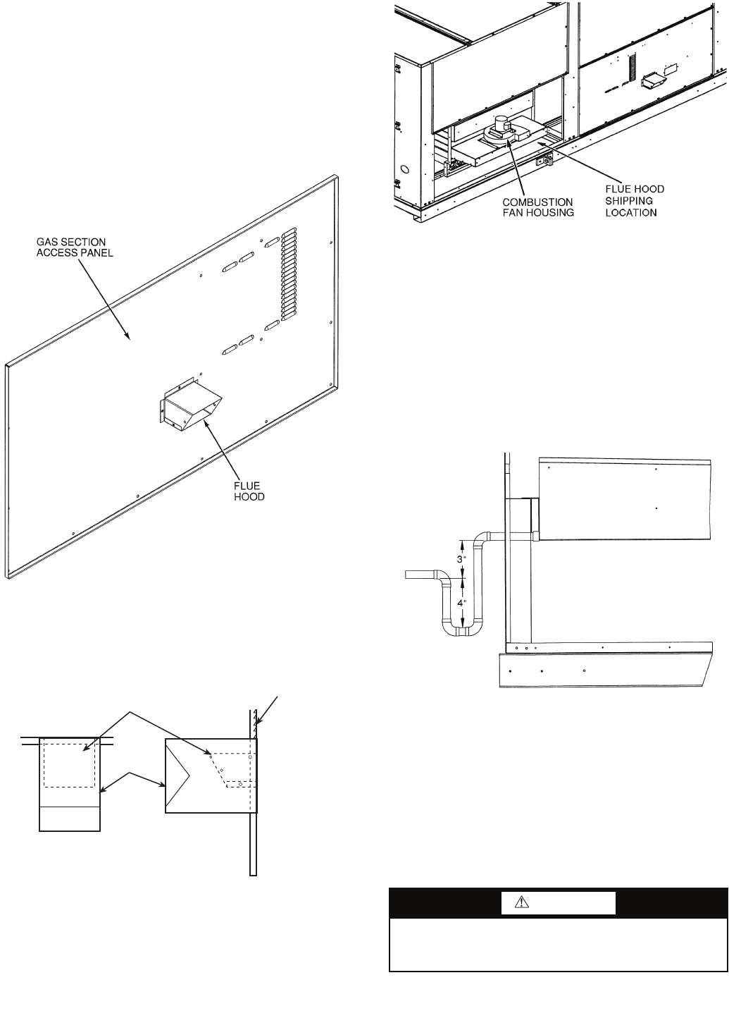
Step 7 — Install Gas Piping — Unit is equipped for
use with natural gas. Installation must conform with local
building codes or, in the absence of local codes, with the Na-
tional Fuel Gas Code, ANSI Z223.1.
Install manual gas shutoff valve with a 1/8-in. NPT pressure
tap for test gage connection at unit. Field gas piping must in-
clude sediment trap and union. See Fig. 18. An 1/8-in. NPT is
also located on the gas manifold adjacent to the gas valve.
WARNING
Do not pressure test gas supply while connected to unit.
Always disconnect union before servicing. Serious injury
could result.
FLUE HOOD
GAS SECTION
ACCESS PANEL
WIND
BAFFLE
TOP VIEW SIDE VIEW
Fig. 14 — Flue Hood Location
(48AJ,AK,AW,AY020-050 Units)
Fig. 15 — Flue Hood Location
(48AJ,AK,AW,AY051 and 060 Units)
a48-3712
a48-4076
Fig. 16 — Combustion Fan Housing Location
(48AJ,AK,AW,AY020-050 Shown)
a48-3823
Fig. 17 — Condensate Drain Trap Piping Details
(Typical Roof Curb or Slab Mount Shown)
a48-3714
20
Size gas-supply piping for 0.5-in. wg maximum pressure
drop. Do not use supply pipe smaller than unit gas connection.
OPTIONAL STAGED GAS UNITS — See Table 7 for staged
gas information. Staging pattern is selected during controls
start-up.
For complete information and service instructions for
Staged Gas Control Units, see Control Operation and Trouble-
shooting literature.
Table 7 — 48A Series Staged Gas Control
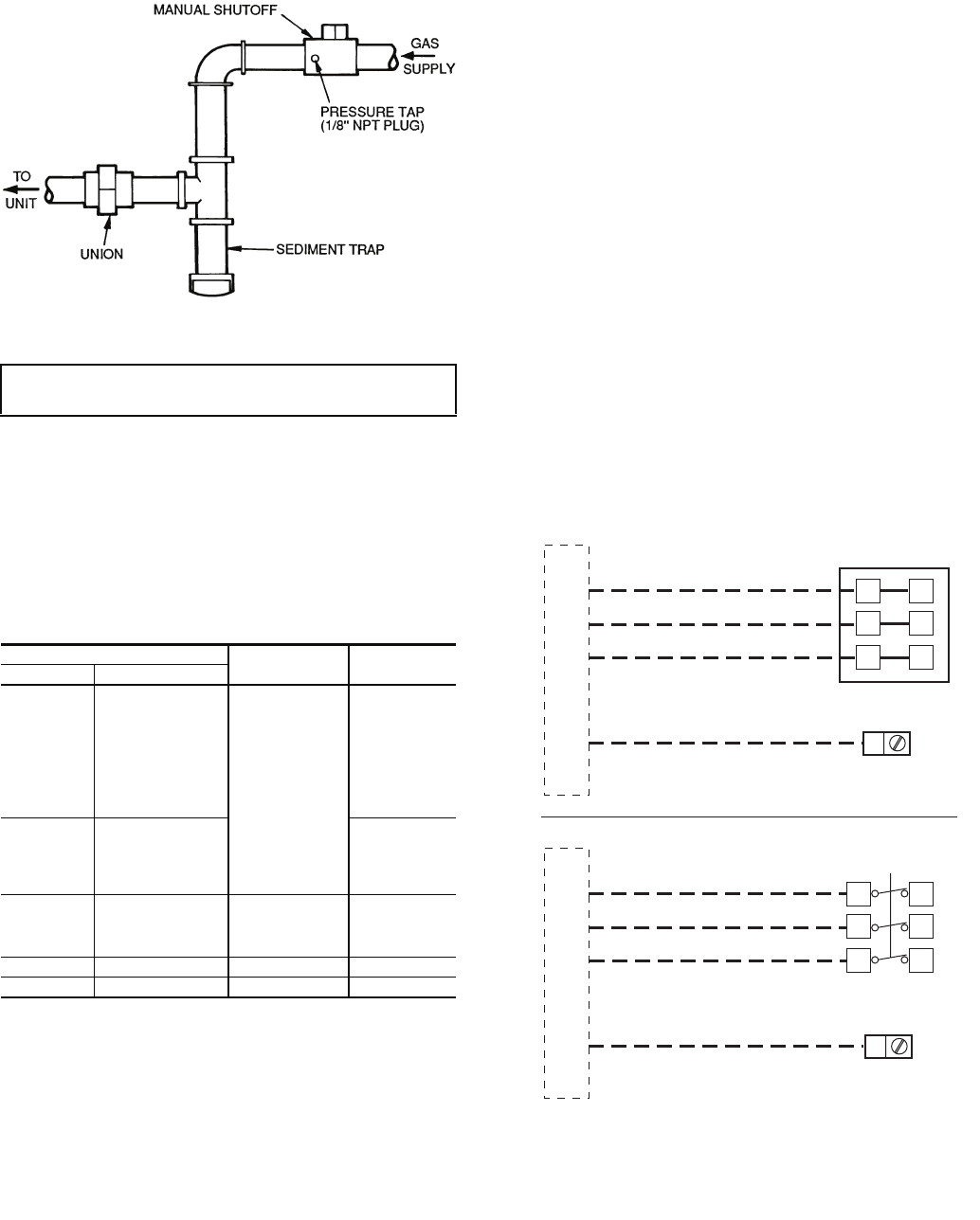
Step 8 — Make Electrical Connections
POWER WIRING — Units are factory wired for the voltage
shown on the unit nameplate.
Provide a unit safety disconnect switch in the main power
supply to each unit (see Fig. 19). Select switch size and mount-
ing location in accordance with applicable local codes or
National Electrical Code (NEC). If combining the functions of
safety disconnect with maximum overcurrent protection
(MOCP) fuses (“fused disconnect”), coordinate safety switch
size with MOCP size data as marked on unit informative plate.
Unit may be equipped with optional factory-installed non-
fused disconnect switch (see Fig. 19). Provide maximum
overcurrent protection devices (fuses or HACR breakers, per
local codes) in branch circuit wiring remote from unit. Observe
requirements of NEC Article 440. Install service switch
upstream of remote fuses if required.
The main power terminal block is suitable for use with
aluminum or copper wire. See Fig. 19. Units have circuit
breakers for compressors, fan motors, and control circuit. The
unit must be electrically grounded in accordance with local
codes, or in absence of local codes, with NEC, ANSI C1-latest
year.
FIELD POWER SUPPLY — Unit is factory wired for volt-
age shown on unit nameplate. See Tables 8A and 8B for elec-
trical data.
Field wiring can be brought into the unit from bottom
(through basepan and roof curb) or through side of unit (corner
post next to control box).
A 31/2-in. NPT coupling for field power wiring and a 3/4-in.
NPT coupling for 24-v control wiring are provided in basepan.
In the side post, there are two 21/2-in. (48A020-035) or 3-in.
(48A036-060) knockouts for the field power wiring. See
Fig. 4-9. If control wiring is to be brought in through the side of
unit, a 7/8-in. diameter hole is provided in the condenser side
post next to the control box.
Do not route control wiring in the same conduit as power
wiring.
If disconnect box is mounted to corner post, be careful not
to drill or screw into the condenser coil.
IMPORTANT: Natural gas pressure at unit gas connection
must not be less than 5 in. wg or greater than 13.5 in. wg.
MODEL NUMBER POSITION NUMBER OF
STAGES HEAT SIZE
5 6,7,8
S
020
025
027
030
035
036
040
041
050
5 stages
Low
T
035
036
040
041
050
High
T
020
025
027
030
7 stages High
T 051,060 9 stages High
S 051,060 11 stages Low
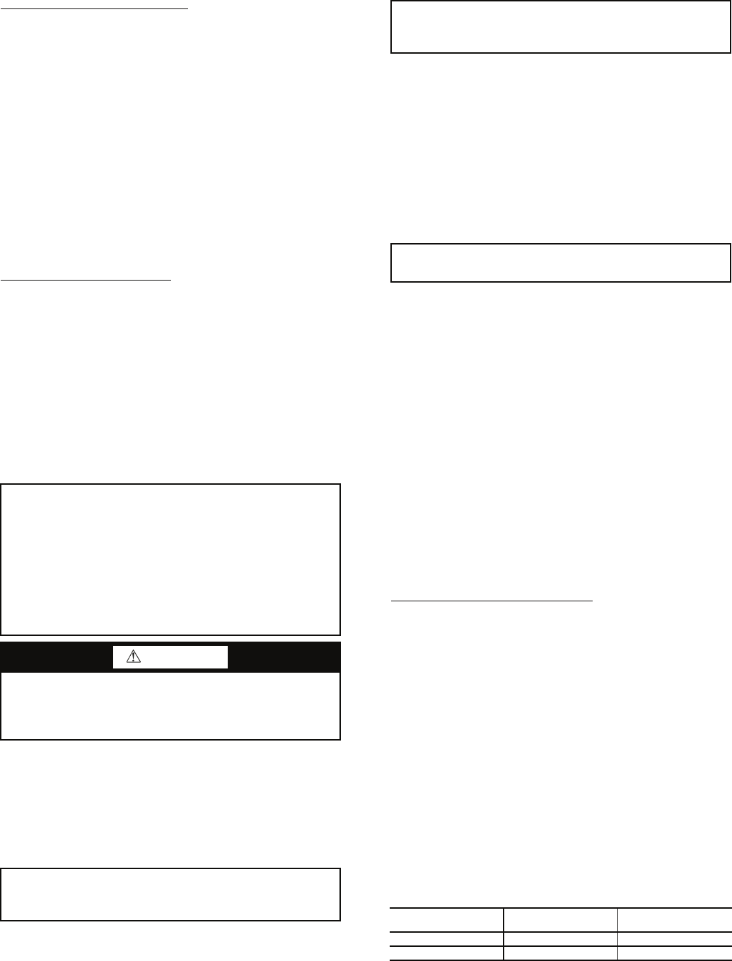
Fig. 18 — Field Gas Piping
a48-2524
FIELD SUPPLIED
DISCONNECT PER NEC
FIELD
POWER
SUPPLY
11 21
22
23
13
12
TB1
EQUIP GND
FIELD POWER WIRING
11 21
22
23
13
12
GND
OPTIONAL
FACTORY-INSTALLED
DISCONNECT
FIELD-INSTALLED DISCONNECT
FACTORY-INSTALLED DISCONNECT
LEGEND
GND — Ground
NEC — National Electrical Code
TB — Terminal Block
Fig. 19 — Field Power Wiring Connections
a48-6977

21
Table 8A — Electrical Data — 48AJ,AK,AW,AY Units without Convenience Outlet
See Legend and Notes on page 24.
UNIT
SIZE
48A
VOLTAGE
3 PH, 60 Hz
VOLTAGE
RANGE
COMPRESSOR CONDENSER
FAN MOTOR
EVAPORATOR
FAN MOTOR
POWER
EXHAUST POWER SUPPLY
Cir A, No. 1 Cir A, No. 2 Cir B, No. 1 Cir B, No. 2
Min Max RLA LRA RLA LRA RLA LRA RLA LRA Qty FLA Hp FLA FLA (total) MCA MOCP*
020
208 187 229 23 184 23 184 23 184 — — 2 6.5
(ea)
516.7 — 104.5 125
23.6 128.1 150
10 30.8 — 120.5 150
23.6 144.1 150
15 46.2 — 139.8 175
23.6 163.4 200
230 207 253 23 184 23 184 23 184 — — 2 6.6
(ea)
515.2 — 103.2 125
23.6 126.8 150
10 28.0 — 117.2 125
23.6 140.8 150
15 42.0 — 134.7 175
23.6 158.3 200
460 414 508 10.2 90 10.2 90 10.2 90 — — 2 3.3
(ea)
57.6 —47.450
12.6 60.0 70
10 14.0 —54.760
12.6 67.3 80
15 21.0 —63.580
12.6 76.1 90
575 518 632 9 73 9 73 9 73 — — 2 2.6
(ea)
56.1 —40.650
9.6 50.2 60
10 11.0 —46.050
9.6 55.6 60
15 17.0 —53.570
9.6 63.1 80
025
208 187 229 21.8 184 25.6 190 25.6 190 — — 2 6.5
(ea)
516.7 — 109.1 125
23.6 132.7 150
10 30.8 — 124.5 150
23.6 148.1 175
15 46.2 — 143.8 175
23.6 167.4 200
230 207 253 21.8 184 25.6 190 25.6 190 — — 2 6.6
(ea)
515.2 — 107.8 125
23.6 131.4 150
10 28.0 — 121.2 125
23.6 144.8 150
15 42.0 — 138.7 175
23.6 162.3 200
460 414 508 11 90 13.5 95 13.5 95 — — 2 3.3
(ea)
57.6 —55.660
12.6 68.2 80
10 14.0 —62.170
12.6 74.7 80
15 21.0 —70.990
12.6 83.5 100
575 518 632 9 73 10.2 75 10.2 75 — — 2 2.6
(ea)
56.1 —43.350
9.6 52.9 60
10 11.0 —48.450
9.6 58.0 60
15 17.0 —55.970
9.6 65.5 80
027
208 187 229 25.6 190 25.6 190 25.6 190 — — 2 6.5
(ea)
10 30.8 — 128.3 150
23.6 151.9 175
15 46.2 — 147.6 175
23.6 171.2 200
20 59.4 — 164.1 200
23.6 187.7 225
230 207 253 25.6 190 25.6 190 25.6 190 — — 2 6.6
(ea)
10 28.0 — 125.0 150
23.6 148.6 175
15 42.0 — 142.5 175
23.6 166.1 200
20 54.0 — 157.5 200
23.6 181.1 225
460 414 508 13.5 95 13.5 95 13.5 95 — — 2 3.3
(ea)
10 14.0 —64.670
12.6 77.2 90
15 21.0 —73.490
12.6 86.0 100
20 27.0 — 80.9 100
12.6 93.5 110
575 518 632 10.2 75 10.2 75 10.2 75 — — 2 2.6
(ea)
10 11.0 —49.660
12.6 62.6 70
15 17.0 —57.170
12.6 69.7 80
20 22.0 —63.380
12.6 75.9 90

22
Table 8A — Electrical Data — 48AJ,AK,AW,AY Units without Convenience Outlet (cont)
See Legend and Notes on page 24.
UNIT
SIZE
48A
VOLTAGE
3 PH, 60 Hz
VOLTAGE
RANGE
COMPRESSOR CONDENSER
FAN MOTOR
EVAPORATOR
FAN MOTOR
POWER
EXHAUST POWER SUPPLY
Cir A, No. 1 Cir A, No. 2 Cir B, No. 1 Cir B, No. 2
Min Max RLA LRA RLA LRA RLA LRA RLA LRA Qty FLA Hp FLA FLA (total) MCA MOCP*
030
208 187 229 23 184 23 184 21.8 184 21.8 184 2 6.5
(ea)
10 30.8 — 141.1 150
23.6 164.7 175
15 46.2 — 160.4 200
23.6 184.0 225
20 59.4 — 176.9 225
23.6 200.5 250
230 207 253 23 184 23 184 21.8 184 21.8 184 2 6.6
(ea)
10 28.0 — 137.8 150
23.6 161.4 175
15 42.0 — 155.3 175
23.6 178.9 200
20 54.0 — 170.5 200
23.6 193.9 225
460 414 508 10.2 90 10.2 90 11 90 11 90 2 3.3
(ea)
10 14.0 —66.580
12.6 79.1 90
15 21.0 —75.390
12.6 87.9 100
20 27.0 — 82.8 100
12.6 95.4 110
575 518 632 9 73 9 73 9 73 9 73 2 2.6
(ea)
10 11.0 —55.060
12.6 68.0 80
15 17.0 —62.570
12.6 75.1 90
20 22.0 —68.790
12.6 81.3 100
035
208 187 229 21.8 184 25.6 190 25.6 190 25.6 190 2 6.5
(ea)
15 46.2 — 169.4 200
23.6 193.6 225
20 59.4 — 185.9 225
23.6 209.5 250
25 74.8 — 205.1 250
23.6 228.7 300
230 207 253 21.8 184 25.6 190 25.6 190 25.6 190 2 6.6
(ea)
15 42.0 — 164.3 200
23.6 187.9 225
20 54.0 — 179.3 225
23.6 202.9 250
25 68.0 — 196.8 250
23.6 220.4 250
460 414 508 11 90 13.5 95 13.5 95 13.5 95 2 3.3
(ea)
15 21.0 — 84.4 100
12.6 97.0 110
20 27.0 — 91.9 110
12.6 104.5 125
25 34.0 — 100.6 125
12.6 113.2 125
575 518 632 9 73 10.2 75 10.2 75 10.2 75 2 2.6
(ea)
15 17.0 —66.180
12.6 78.7 90
20 22.0 —72.390
12.6 84.9 100
25 27.0 — 78.6 100
12.6 91.2 110
036
208 187 229 21.8 184 25.6 190 25.6 190 25.6 190 4 6.5
(ea)
15 46.2 — 182.4 225
23.6 206.0 250
20 59.4 — 198.9 250
23.6 222.5 250
25 74.8 — 218.1 250
23.6 241.7 300
230 207 253 21.8 184 25.6 190 25.6 190 25.6 190 4 6.6
(ea)
15 42.0 — 177.5 200
23.6 201.1 225
20 54.0 — 192.5 225
23.6 216.1 250
25 68.0 — 210.0 250
23.6 233.6 300
460 414 508 11 90 13.5 95 13.5 95 13.5 95 4 3.3
(ea)
15 21.0 — 91.0 110
12.6 103.6 110
20 27.0 — 98.5 125
12.6 111.1 125
25 34.0 — 107.2 125
12.6 119.8 150
575 518 632 9 73 10.2 75 10.2 75 10.2 75 4 2.6
(ea)
15 17.0 —71.380
9.6 80.9 90
20 22.0 —77.590
9.6 87.1 100
25 27.0 — 83.8 110
9.6 93.4 110

23
Table 8A — Electrical Data — 48AJ,AK,AW,AY Units without Convenience Outlet (cont)
See Legend and Notes on page 24.
UNIT
SIZE
48A
VOLTAGE
3 PH, 60 Hz
VOLTAGE
RANGE
COMPRESSOR CONDENSER
FAN MOTOR
EVAPORATOR
FAN MOTOR
POWER
EXHAUST POWER SUPPLY
Cir A, No. 1 Cir A, No. 2 Cir B, No. 1 Cir B, No. 2
Min Max RLA LRA RLA LRA RLA LRA RLA LRA Qty FLA Hp FLA FLA (total) MCA MOCP*
040
208 187 229 25.6 190 25.6 190 34.3 265 34.3 265 4 6.5
(ea)
15 46.2 — 203.6 225
23.6 227.2 250
20 59.4 — 220.1 250
23.6 243.7 300
25 74.8 — 239.3 300
23.6 262.4 300
230 207 253 25.6 190 25.6 190 34.3 265 34.3 265 4 6.6
(ea)
15 42.0 — 198.7 225
23.6 222.3 250
20 54.0 — 213.7 250
23.6 237.3 250
25 68.0 — 231.2 250
23.6 254.8 300
460 414 508 13.5 95 13.5 95 16 120 16 120 4 3.3
(ea)
15 21.0 — 98.5 110
12.6 111.1 125
20 27.0 — 106.0 125
12.6 118.6 125
25 34.0 — 114.7 125
12.6 127.3 150
575 518 632 10.2 75 10.2 75 12.9 80 12.9 80 4 2.6
(ea)
15 17.0 —77.990
12.6 90.5 100
20 22.0 — 84.1 100
12.6 96.7 110
25 27.0 — 90.4 110
12.6 103.0 125
041
208 187 229 25.6 190 25.6 190 34.3 265 34.3 265 4 6.5
(ea)
15 46.2 — 203.6 225
23.6 227.2 250
20 59.4 — 220.1 250
23.6 243.7 300
25 74.8 — 239.3 300
23.6 262.9 300
230 207 253 25.6 190 25.6 190 34.3 265 34.3 265 4 6.6
(ea)
15 42.0 — 198.7 225
23.6 222.3 250
20 54.0 — 213.7 250
23.6 237.3 250
25 68.0 — 231.2 250
23.6 254.8 300
460 414 508 13.5 95 13.5 95 16 120 16 120 4 3.3
(ea)
15 21.0 — 98.5 110
12.6 111.1 125
20 27.0 — 106.0 125
12.6 118.6 125
25 34.0 — 114.7 125
12.6 127.3 150
575 518 632 10.2 75 10.2 75 12.9 80 12.9 80 4 2.6
(ea)
15 17.0 —77.990
9.6 87.5 100
20 22.0 — 84.1 100
9.6 93.7 110
25 27.0 — 90.4 110
9.6 100.0 125
050
208 187 229 34.3 265 34.3 265 34.3 265 47 380 4 6.5
(ea)
20 59.4 — 250.2 300
23.6 273.8 300
25 74.8 — 269.4 300
23.6 293.0 350
30 88.0 — 285.9 350
23.6 309.5 350
230 207 253 34.3 265 34.3 265 34.3 265 47 380 4 6.6
(ea)
20 54.0 — 243.8 250
23.6 267.4 300
25 68.0 — 261.3 300
23.6 284.9 300
30 80.0 — 276.3 350
23.6 299.9 350
460 414 508 16 120 16 120 16 120 22.4 175 4 3.3
(ea)
20 27.0 — 117.4 125
12.6 130.0 150
25 34.0 — 126.1 150
12.6 138.7 150
30 40.0 — 133.6 150
12.6 146.2 175
575 518 632 12.9 80 12.9 80 12.9 80 18.6 140 4 2.6
(ea)
20 22.0 — 95.2 110
12.6 107.8 125
25 27.0 — 101.5 125
12.6 114.1 125
30 32.0 — 107.7 125
12.6 120.3 150
24
Table 8A — Electrical Data — 48AJ,AK,AW,AY Units without Convenience Outlet (cont)
LEGEND
*Fuse or HACR circuit breaker per NEC.
NOTES:
1. In compliance with NEC requirements for multimotor and combination
load equipment (refer to NEC Articles 430 and 440), the overcurrent
protective device for the unit shall be fuse or HACR breaker. The
Canadian units may be fuse or circuit breaker.
2. Unbalanced 3-Phase Supply Voltage
Never operate a motor where a phase imbalance in supply voltage is
greater than 2%. Use the following formula to determine the percent
of voltage imbalance.
% Voltage imbalance
Example: Supply voltage is 460-3-60.
AB = 452 v
BC = 464 v
AC = 455 v
= 457
Determine maximum deviation from average voltage.
(AB) 457 – 452 = 5 v
(BC) 464 – 457 = 7 v
(AC) 457 – 455 = 2 v
Maximum deviation is 7 v.
Determine percent of voltage imbalance.
% Voltage Imbalance = 100 x
= 1.53%
This amount of phase imbalance is satisfactory as it is below the max-
imum allowable 2%.
UNIT
SIZE
48A
VOLTAGE
3 PH, 60 Hz
VOLTAGE
RANGE
COMPRESSOR CONDENSER
FAN MOTOR
EVAPORATOR
FAN MOTOR
POWER
EXHAUST POWER SUPPLY
Cir A, No. 1 Cir A, No. 2 Cir B, No. 1 Cir B, No. 2
Min Max RLA LRA RLA LRA RLA LRA RLA LRA Qty FLA Hp FLA FLA (total) MCA MOCP*
051
208 187 229 34.3 265 34.3 265 34.3 265 34.3 265 6 6.5
(ea)
20 59.4 — 250.5 300
35.4 285.9 300
25 74.8 — 269.7 300
35.4 305.1 350
30 88 — 286.2 350
35.4 321.6 400
40 114 — 318.7 400
35.4 354.1 450
230 207 253 34.3 265 34.3 265 34.3 265 34.3 265 6 6.6
(ea)
20 54 — 244.3 250
35.4 279.7 300
25 68 — 261.8 300
35.4 297.2 350
30 80 — 276.8 350
35.4 312.2 350
40 104 — 306.8 400
35.4 342.2 400
460 414 508 16 120 16 120 16 120 16 120 6 3.3
(ea)
20 27 — 117.6 125
18.9 136.5 150
25 34 — 126.3 150
18.9 145.2 175
30 40 — 133.8 150
18.9 152.7 175
40 52 — 148.8 200
18.9 167.7 200
575 518 632 12.9 80 12.9 80 12.9 80 12.9 80 6 2.6
(ea)
20 22 — 94.7 110
14.4 109.1 125
25 27 — 101.0 125
14.4 115.4 125
30 32 — 107.2 125
14.4 121.6 150
40 41 — 118.5 150
14.4 132.9 150
060
208 187 229 40.8 265 47 380 40.8 265 47 380 6 6.5
(ea)
25 75.0 — 308.1 350
35.4 343.5 400
30 88.0 — 324.6 400
35.4 360.0 400
40 114.0 — 357.1 450
35.4 392.5 450
230 207 253 40.8 265 47 380 40.8 265 47 380 6 6.6
(ea)
25 68.0 — 300.2 350
35.4 335.6 350
30 80.0 — 315.2 350
35.4 350.6 400
40 104.0 — 345.2 400
35.4 380.6 450
460 414 508 20.2 135 22.4 175 20.2 135 22.4 175 6 3.3
(ea)
25 34.0 — 147.5 175
18.9 166.4 175
30 40.0 — 155.0 175
18.9 173.9 200
40 52.0 — 170.0 200
18.9 188.9 225
575 518 632 16.6 120 18.6 140 16.6 120 18.6 140 6 2.6
(ea)
25 27.0 — 119.8 125
18.9 138.7 150
30 32.0 — 126.0 150
18.9 144.9 175
40 41.0 — 137.3 175
18.9 156.2 175
FLA — Full Load Amps
HACR — Heating, Air Conditioning and Refrigeration
LRA — Locked Rotor Amps
MCA — Minimum Circuit Amps
MOCP — Maximum Overcurrent Protection
NEC — National Electrical Code
RLA — Rated Load Amps
= 100 x max voltage deviation from average voltage
average voltage
Average Voltage = 452 + 464 + 455
3
= 1371
3
IMPORTANT: If the supply voltage phase imbalance is more than
2%, contact your local electric utility company immediately.
7
457

25
Table 8B — Electrical Data — 48AJ,AK,AW,AY Units with Convenience Outlet
See Legend and Notes on page 28.
UNIT
SIZE
48A
VOLTAGE
3 PH, 60 Hz
VOLTAGE
RANGE
COMPRESSOR CONDENSER
FAN MOTOR
EVAPORATOR
FAN MOTOR
POWER
EXHAUST
CONVENIENCE
OUTLET POWER SUPPLY
Cir A, No. 1 Cir A, No. 2 Cir B, No. 1 Cir B, No. 2
Min Max RLA LRA RLA LRA RLA LRA RLA LRA Qty FLA Hp FLA FLA (total) FLA MCA Fuse or
HACR Brkr*
020
208 187 229 23 184 23 184 23 184 — — 2 6.5
(ea)
516.7 — 7.0 111.5 125
23.6 7.0 135.2 150
10 30.8 — 7.0 127.5 150
23.6 7.0 151.1 175
15 46.2 — 7.0 146.8 175
23.6 7.0 170.4 200
230 207 253 23 184 23 184 23 184 — — 2 6.6
(ea)
515.2 — 7.0 110.2 125
23.6 7.0 133.9 150
10 28.0 — 7.0 124.2 150
23.6 7.0 147.8 175
15 42.0 — 7.0 141.7 175
23.6 7.0 165.3 200
460 414 508 10.2 90 10.2 90 10.2 90 — — 2 3.3
(ea)
57.6 — 3.5 50.9 60
12.6 3.5 64.1 70
10 14.0 — 3.5 58.2 70
12.6 3.5 70.8 80
15 21.0 — 3.5 67.0 80
12.6 3.5 79.6 100
575 518 632 9 73 9 73 9 73 — — 2 2.6
(ea)
56.1 — 2.5 43.1 50
9.6 2.5 52.8 60
10 11.0 — 2.5 48.5 50
9.6 2.5 58.1 60
15 17.0 —2.556.0
70
9.6 2.5 65.6 80
025
208 187 229 21.8 184 25.6 190 25.6 190 — — 2 6.5
(ea)
516.7 — 7.0 116.1 125
23.6 7.0 139.7 150
10 30.8 — 7.0 131.5 150
23.6 7.0 155.1 175
15 46.2 — 7.0 150.8 175
23.6 7.0 174.4 200
230 207 253 21.8 184 25.6 190 25.6 190 — — 2 6.6
(ea)
515.2 — 7.0 114.8 125
23.6 7.0 138.4 150
10 28.0 — 7.0 128.2 150
23.6 7.0 151.8 175
15 42.0 — 7.0 145.7 175
23.6 7.0 169.3 200
460 414 508 11 90 13.5 95 13.5 95 — — 2 3.3
(ea)
57.6 — 3.5 59.1 70
12.6 3.5 71.7 80
10 14.0 — 3.5 65.6 70
12.6 3.5 78.2 90
15 21.0 — 3.5 74.4 90
12.6 3.5 87.0 100
575 518 632 9 73 10.2 75 10.2 75 — — 2 2.6
(ea)
56.9 — 2.5 46.6 50
6.1 2.5 52.7 60
10 11.0 — 2.5 50.9 60
6.1 2.5 57.0 60
15 17.0 — 2.5 58.4 70
6.1 2.5 64.5 80
027
208 187 229 25.6 190 25.6 190 25.6 190 — — 2 6.5
(ea)
10 30.8 — 7.0 135.3 150
23.6 7.0 158.9 175
15 46.2 — 7.0 154.6 200
23.6 7.0 178.2 200
20 59.4 — 7.0 171.1 225
23.6 7.0 194.7 250
230 207 253 25.6 190 25.6 190 25.6 190 — — 2 6.6
(ea)
10 28.0 — 7.0 132.0 150
23.6 7.0 155.6 175
15 42.0 — 7.0 149.5 175
23.6 7.0 173.1 200
20 54.0 — 7.0 164.5 200
23.6 7.0 188.1 225
460 414 508 13.5 95 13.5 95 13.5 95 — — 2 3.3
(ea)
10 14.0 — 3.5 68.1 80
12.6 3.5 80.7 90
15 21.0 — 3.5 76.9 90
12.6 3.5 89.5 110
20 27.0 — 3.5 84.4 110
12.6 3.5 97.0 110
575 518 632 10.2 75 10.2 75 10.2 75 — — 2 2.6
(ea)
10 11.0 — 2.5 52.1 60
9.6 2.5 61.7 70
15 17.0 — 2.5 59.6 70
9.6 2.5 69.2 80
20 22.0 — 2.5 65.8 80
9.6 2.5 75.4 90

26
Table 8B — Electrical Data — 48AJ,AK,AW,AY Units with Convenience Outlet (cont)
See Legend and Notes on page 28.
UNIT
SIZE
48A
VOLTAGE
3 PH, 60 Hz
VOLTAGE
RANGE
COMPRESSOR CONDENSER
FAN MOTOR
EVAPORATOR
FAN MOTOR
POWER
EXHAUST
CONVENIENCE
OUTLET POWER SUPPLY
Cir A, No. 1 Cir A, No. 2 Cir B, No. 1 Cir B, No. 2
Min Max RLA LRA RLA LRA RLA LRA RLA LRA Qty FLA Hp FLA FLA (total) FLA MCA Fuse or
HACR Brkr*
030
208 187 229 23 184 23 184 21.8 184 21.8 184 2 6.5
(ea)
10 30.8 — 7.0 148.1 175
23.6 7.0 171.7 200
15 46.2 — 7.0 167.4 200
23.6 7.0 191.0 225
20 59.4 — 7.0 183.9 225
23.6 7.0 207.5 250
230 207 253 23 184 23 184 21.8 184 21.8 184 2 6.6
(ea)
10 28.0 — 7.0 144.8 150
23.6 7.0 168.4 175
15 42.0 — 7.0 162.3 200
23.6 7.0 185.9 225
20 54.0 — 7.0 177.3 225
23.6 7.0 200.9 250
460 414 508 10.2 90 10.2 90 11 90 11 90 2 3.3
(ea)
10 14.0 — 3.5 70.0 80
12.6 3.5 82.6 90
15 21.0 — 3.5 78.8 90
12.6 3.5 91.4 110
20 27.0 — 3.5 86.3 110
12.6 3.5 98.9 125
575 5186329739739739732 2.6
(ea)
10 11.0 — 2.5 57.5 60
9.6 2.5 67.1 70
15 17.0 — 2.5 65.0 80
9.6 2.5 74.6 90
20 22.0 — 2.5 71.2 90
9.6 2.5 80.8 100
035
208 187 229 21.8 184 25.6 190 25.6 190 25.6 190 2 6.5
(ea)
15 46.2 — 7.0 176.4 200
23.6 7.0 200.0 225
20 59.4 — 7.0 192.9 250
23.6 7.0 216.5 250
25 74.8 — 7.0 212.1 250
23.6 7.0 235.7 300
230 207 253 21.8 184 25.6 190 25.6 190 25.6 190 2 6.6
(ea)
15 42.0 — 7.0 171.3 200
23.6 7.0 194.9 225
20 54.0 — 7.0 186.3 225
23.6 7.0 209.9 250
25 68.0 — 7.0 203.8 250
23.6 7.0 227.4 250
460 414 508 11 90 13.5 95 13.5 95 13.5 95 2 3.3
(ea)
15 21.0 — 3.5 87.9 100
12.6 3.5 100.5 110
20 27.0 — 3.5 95.4 110
12.6 3.5 108.0 125
25 34.0 — 3.5 104.1 125
12.6 3.5 116.7 150
575 518 632 9 73 10.2 75 10.2 75 10.2 75 2 2.6
(ea)
15 17.0 — 2.5 68.6 80
9.6 2.5 78.2 90
20 22.0 — 2.5 74.8 90
9.6 2.5 84.4 100
25 27.0 — 2.5 81.1 100
9.6 2.5 90.7 110
036
208 187 229 21.8 184 25.6 190 25.6 190 25.6 190 4 6.5
(ea)
15 46.2 — 7.0 189.4 225
23.6 7.0 213.0 250
20 59.4 — 7.0 205.9 250
23.6 7.0 229.5 250
25 74.8 — 7.0 225.1 250
23.6 7.0 248.7 300
230 207 253 21.8 184 25.6 190 25.6 190 25.6 190 4 6.6
(ea)
15 42.0 — 7.0 184.5 225
23.6 7.0 208.1 250
20 54.0 — 7.0 199.5 250
23.6 7.0 223.1 250
25 68.0 — 7.0 217.0 250
23.6 7.0 240.6 300
460 414 508 11 90 13.5 95 13.5 95 13.5 95 4 3.3
(ea)
15 21.0 — 3.5 94.5 110
12.6 3.5 107.1 125
20 27.0 — 3.5 102.0 125
12.6 3.5 114.6 125
25 34.0 — 3.5 110.7 125
12.6 3.5 123.3 150
575 518 632 9 73 10.2 75 10.2 75 10.2 75 4 2.6
(ea)
15 17.0 — 2.5 73.8 90
9.6 2.5 83.4 100
20 22.0 — 2.5 80.0 100
9.6 2.5 89.6 110
25 27.0 — 2.5 86.3 110
9.6 2.5 95.9 110

27
Table 8B — Electrical Data — 48AJ,AK,AW,AY Units with Convenience Outlet (cont)
See Legend and Notes on page 28.
UNIT
SIZE
48A
VOLTAGE
3 PH, 60 Hz
VOLTAGE
RANGE
COMPRESSOR CONDENSER
FAN MOTOR
EVAPORATOR
FAN MOTOR
POWER
EXHAUST
CONVENIENCE
OUTLET POWER SUPPLY
Cir A, No. 1 Cir A, No. 2 Cir B, No. 1 Cir B, No. 2
Min Max RLA LRA RLA LRA RLA LRA RLA LRA Qty FLA Hp FLA FLA (total) FLA MCA Fuse or
HACR Brkr*
040
208 187 229 25.6 190 25.6 190 34.3 265 34.3 265 2 6.5
(ea)
15 46.2 — 7.0 210.6 250
23.6 7.0 234.2 250
20 59.4 — 7.0 227.1 250
23.6 7.0 250.7 300
25 74.8 — 7.0 246.3 300
23.6 7.0 269.9 300
230 207 253 25.6 190 25.6 190 34.3 265 34.3 265 2 6.6
(ea)
15 42.0 — 7.0 205.7 225
23.6 7.0 229.3 250
20 54.0 — 7.0 220.7 250
23.6 7.0 244.3 250
25 68.0 — 7.0 238.2 300
23.6 7.0 261.8 300
460 414 508 13.5 95 13.5 95 16.0 120 16.0 120 2 3.3
(ea)
15 21.0 — 3.5 102.0 110
12.6 3.5 114.6 125
20 27.0 — 3.5 109.5 125
12.6 3.5 122.1 125
25 34.0 — 3.5 118.2 150
12.6 3.5 130.8 150
575 518 632 10.2 75 10.2 75 12.9 80 12.9 80 2 2.6
(ea)
15 17.0 — 2.5 80.4 90
9.6 2.5 90.0 100
20 22.0 — 2.5 86.6 100
9.6 2.5 96.2 110
25 27.0 — 2.5 92.9 110
9.6 2.5 102.5 125
041
208 187 229 25.6 190 25.6 190 34.3 265 34.3 265 4 6.5
(ea)
15 46.2 — 7.0 210.6 250
23.6 7.0 234.2 250
20 59.4 — 7.0 227.1 250
23.6 7.0 250.7 300
25 74.8 — 7.0 246.3 300
23.6 7.0 269.9 300
230 207 253 25.6 190 25.6 190 34.3 265 34.3 265 4 6.6
(ea)
15 42.0 — 7.0 205.7 225
23.6 7.0 229.3 250
20 54.0 — 7.0 220.7 250
23.6 7.0 244.3 250
25 68.0 — 7.0 238.2 300
23.6 7.0 261.8 300
460 414 508 13.5 95 13.5 95 16 120 16 120 4 3.3
(ea)
15 21.0 — 3.5 102.0 110
12.6 3.5 114.6 125
20 27.0 — 3.5 109.5 125
12.6 3.5 122.1 125
25 34.0 — 3.5 118.2 150
12.6 3.5 130.8 150
575 518 632 10.2 75 10.2 75 12.9 80 12.9 80 4 2.6
(ea)
15 17.0 — 2.5 80.4 90
9.6 2.5 90.0 100
20 22.0 — 2.5 86.6 100
9.6 2.5 96.2 110
25 27.0 — 2.5 92.9 110
9.6 2.5 102.5 125
050
208 187 229 34.3 265 34.3 265 34.3 265 47 380 4 6.5
(ea)
20 59.0 — 7.0 257.2 300
23.6 7.0 280.8 300
25 75.0 — 7.0 276.4 350
23.6 7.0 300.0 350
30 88.0 — 7.0 292.9 350
23.6 7.0 316.5 400
230 207 253 34.3 265 34.3 265 34.3 265 47 380 4 6.6
(ea)
20 54.0 — 7.0 250.8 300
23.6 7.0 274.4 300
25 68.0 — 7.0 268.3 300
23.6 7.0 291.9 350
30 80.0 — 7.0 283.3 350
23.6 7.0 306.9 350
460 414 508 16 120 16 120 16 120 22.4 175 4 3.3
(ea)
20 27.0 — 3.5 120.9 125
12.6 3.5 133.5 150
25 34.0 — 3.5 129.6 150
12.6 3.5 142.2 175
30 40.0 — 3.5 137.1 175
12.6 3.5 149.7 175
575 518 632 12.9 80 12.9 80 12.9 80 18.6 140 4 2.6
(ea)
20 22.0 — 2.5 97.7 110
9.6 2.5 107.3 125
25 27.0 — 2.5 104.0 125
9.6 2.5 113.6 125
30 32.0 — 2.5 110.2 125
9.6 2.5 119.8 150
28
Table 8B — Electrical Data — 48AJ,AK,AW,AY Units with Convenience Outlet (cont)
LEGEND
*Fuse or HACR circuit breaker per NEC.
NOTES:
1. In compliance with NEC requirements for multimotor and combination load
equipment (refer to NEC Articles 430 and 440), the overcurrent protective
device for the unit shall be fuse or HACR breaker. The Canadian units may
be fuse or circuit breaker.
2. Unbalanced 3-Phase Supply Voltage
Never operate a motor where a phase imbalance in supply voltage is
greater than 2%. Use the following formula to determine the percent of volt-
age imbalance.
% Voltage imbalance
Example: Supply voltage is 460-3-60.
AB = 452 v
BC = 464 v
AC = 455 v
= 457
Determine maximum deviation from average voltage.
(AB) 457 – 452 = 5 v
(BC) 464 – 457 = 7 v
(AC) 457 – 455 = 2 v
Maximum deviation is 7 v.
Determine percent of voltage imbalance.
% Voltage Imbalance = 100 x
= 1.53%
This amount of phase imbalance is satisfactory as it is below the maximum
allowable 2%.
UNIT
SIZE
48A
VOLTAGE
3 PH, 60 Hz
VOLTAGE
RANGE
COMPRESSOR CONDENSER
FAN MOTOR
EVAPORATOR
FAN MOTOR
POWER
EXHAUST
CONVENIENCE
OUTLET POWER SUPPLY
Cir A, No. 1 Cir A, No. 2 Cir B, No. 1 Cir B, No. 2
Min Max RLA LRA RLA LRA RLA LRA RLA LRA Qty FLA Hp FLA FLA (total) FLA MCA Fuse or
HACR Brkr*
051
208 187 229 34.3 265 34.3 265 34.3 265 34.3 265 6 6.5
(ea)
20 59.4 — 7.0 257.5 300
35.4 7.0 292.9 350
25 74.8 — 7.0 276.7 350
35.4 7.0 312.1 350
30 88 — 7.0 293.2 350
35.4 7.0 328.6 400
40 114 — 7.0 325.7 400
35.4 7.0 361.1 450
230 207 253 34.3 265 34.3 265 34.3 265 34.3 265 6 6.6
(ea)
20 54 — 7.0 251.3 300
35.4 7.0 286.7 300
25 68 — 7.0 268.8 300
35.4 7.0 304.2 350
30 80 — 7.0 283.8 350
35.4 7.0 319.2 350
40 104 — 7.0 313.8 400
35.4 7.0 349.2 450
460 414 508 16 120 16 120 16 120 16 120 6 3.3
(ea)
20 27 — 3.5 121.1 125
18.9 3.5 140.0 150
25 34 — 3.5 129.8 150
18.9 3.5 148.7 175
30 40 — 3.5 137.3 175
18.9 3.5 156.2 175
40 52 — 3.5 152.3 200
18.9 3.5 171.2 200
575 518 632 12.9 80 12.9 80 12.9 80 12.9 80 6 2.6
(ea)
20 22 — 2.5 97.2 110
14.4 2.5 111.6 125
25 27 — 2.5 103.5 125
14.4 2.5 117.9 125
30 32 — 2.5 109.7 125
14.4 2.5 124.1 150
40 41 — 2.5 121.0 150
14.4 2.5 135.4 175
060
208 187 229 40.8 265 47 380 40.8 265 47 380 6 6.5
(ea)
25 75.0 — 7.0 315.1 350
35.4 7.0 350.5 400
30 88.0 — 7.0 331.6 400
35.4 7.0 367.0 450
40 114.0 — 7.0 364.1 450
35.4 7.0 399.5 500
230 207 253 40.8 265 47 380 40.8 265 47 380 6 6.6
(ea)
25 68.0 — 7.0 307.2 350
35.4 7.0 342.6 400
30 80.0 — 7.0 322.2 400
35.4 7.0 357.6 400
40 104.0 — 7.0 352.2 450
35.4 7.0 387.6 450
460 414 508 20.2 135 22.4 175 20.2 135 22.4 175 6 3.3
(ea)
25 34.0 — 3.5 151.0 175
18.9 3.5 169.9 200
30 40.0 — 3.5 158.5 175
18.9 3.5 177.4 200
40 52.0 — 3.5 173.5 225
18.9 3.5 192.4 225
575 518 632 16.6 120 18.6 140 16.6 120 18.6 140 6 2.6
(ea)
25 27.0 — 2.5 122.3 125
14.4 2.5 136.7 150
30 32.0 — 2.5 128.5 150
14.4 2.5 142.9 150
40 41.0 — 2.5 139.8 175
14.4 2.5 154.2 175
FLA — Full Load Amps
HACR — Heating, Air Conditioning and Refrigeration
LRA — Locked Rotor Amps
MCA — Minimum Circuit Amps
NEC — National Electrical Code
RLA — Rated Load Amps
= 100 x max voltage deviation from average voltage
average voltage
Average Voltage = 452 + 464 + 455
3
= 1371
3
IMPORTANT: If the supply voltage phase imbalance is more than 2%,
contact your local electric utility company immediately.
7
457
29
Routing Through Bottom of Unit — If wiring is brought in
through bottom of unit, use field-supplied watertight conduit to
route power wiring through the 31/2-in. diameter hole provided
in the unit basepan.
Install conduit connector in unit basepan as shown in
Fig. 4-9. Route power and ground lines through connector to
terminal connections in unit control box as shown on unit
wiring diagram and Fig. 19.
Use strain relief going into control box through 35/8-in.
diameter hole provided. After wires are in unit control box,
connect to power terminal block (see Power Wiring section on
page 20).
Low-voltage wiring must be run in watertight conduit from
the basepan to control box and through 7/8-in. diameter hole
provided in bottom of unit control box. Field-supplied strain
relief must be used going into the box. After wiring is in
control box, make connections to proper terminals on terminal
blocks (see Field Control Wiring section on this page).
Routing Through Side of Unit — Route power wiring in
field-supplied watertight conduit into unit through 21/2-in. (siz-
es 020-035) or 3-in. (sizes 036-060) hole.
Use field-supplied strain relief going into control box
through 35/8-in. diameter hole provided. After wires are in unit
control box, connect to power terminal block (see Power Wir-
ing section on page 20).
Bring low-voltage control wiring through the 7/8-in. diame-
ter hole provided in the condenser section side post. Use strain
relief going into 7/8-in. diameter hole in bottom of unit control
box.
After wiring is in control box, make connection to proper
terminals on terminal blocks (see Field Control Wiring section
below).
Affix crankcase heater sticker (located in the installers
packet) to unit disconnect switch.
Voltage to compressor terminals during compressor operation
must be within the voltage range indicated on the unit name-
plate. Phases must be balanced within 2%.
Use the formula in Tables 8A and 8B to determine the per-
centage of voltage imbalance.
Unit failure as a result of operation on improper line voltage
or excessive phase imbalance constitutes abuse and may cause
damage to electrical components.
For transformer 1 move the black wires connected to termi-
nal H2 and connect it to terminal H3.
For transformers 2-4, that are used for the 24-volt control
circuits, connect as follows:
1. Remove cap from red (208 v) wire.
2. Remove cap from spliced orange (230 v) wire. Discon-
nect orange wire from black unit power wire.
3. Cap orange wire.
4. Splice red wire and black unit power wire. Cap wires.
If the unit is equipped with the optional convenience outlet
connect the yellow wire to H2 on transformer 5.
FIELD CONTROL WIRING — The 48A Series units sup-
port a large number of control options that can impact the field
control wiring.
The control options that the unit can provide relate to the
following parameters:
• CV (constant volume), VAV (variable air volume),
VVT® (variable volume variable temperature) or
Carrier TEMP system control operation.
• Stand-alone with a thermostat (CV) or with a space sen-
sor (CV and VAV)
• Network application with CCN (Carrier Comfort
Network®) or other networks
• Demand ventilation with CO2 sensor
• Economizer and economizer with changeover control
• Staged gas heat
• Building and duct static pressure control
• Fire shutdown and smoke control
• Diagnostics and monitoring
For constant volume applications a thermostat (T-Stat) or
space temperature sensor (SPT) will be required.
T-STAT (Conventional Thermostat) — Unit can be con-
trolled with a Carrier-approved accessory electro-mechanical
or electronic thermostat that has two stages of cooling, two
stages of heating control and an output for indoor fan control. It
may also include time of day scheduling or use the scheduling
routines built into the ComfortLink™ controls.
Install thermostat according to the installation instructions
included with accessory thermostat and the unit wiring dia-
grams. Locate thermostat assembly on a solid interior wall in
the conditioned space to sense average temperature.
Route thermostat cable or equivalent single leads of colored
wire from subbase terminals through conduit into unit to low-
voltage connection in the main control box. For thermostat
TB4 connections see Fig. 20.
NOTE: For wire runs up to 50 ft, use no. 18 AWG (American
Wire Gage) insulated wire (35 C minimum). For 50 to 75 ft,
use no. 16 AWG insulated wire (35 C minimum). For over
75 ft, use no. 14 AWG insulated wire (35 C Minimum). All
wire larger than no. 18 AWG cannot be directly connected at
the thermostat and will require a junction box and splice at the
thermostat. Set heat anticipator settings as follows:
Settings may be changed slightly to provide a greater degree of
comfort for a particular installation.
IMPORTANT: The VAV (variable air volume) units use
variable frequency drives, which generate and can radiate
radio frequency energy. If units are not installed and used
in accordance with these instructions, they may cause radio
interference. They have been tested and found to comply
with limits of a Class A computing device as defined by
FCC (Federal Communications Commission) regulations,
Subpart J of Part 15, which are designed to provide reason-
able protection against such interference when operated in
a commercial environment.
WARNING
The unit must be electrically grounded in accordance with
local codes and NEC ANSI/NFPA 70 (National Fire
Protection Association). Electrical shock could cause per-
sonal injury.
IMPORTANT: If the supply voltage phase imbalance is
more than 2%, contact your local electric utility company
immediately.
IMPORTANT: On 208/230-v units, transformers 1-5 are
wired for 230-v. If 208/230-v unit is to be run with 208-v
power supply, the transformers must be rewired as follows:
IMPORTANT: BE CERTAIN UNUSED WIRES ARE
CAPPED. Failure to do so may damage the transformers.
SIZE STAGE 1
(W1) ON
STAGE 2
(W1 and W2) ON
020-050 0.24 0.13
051, 060 0.36 0.13
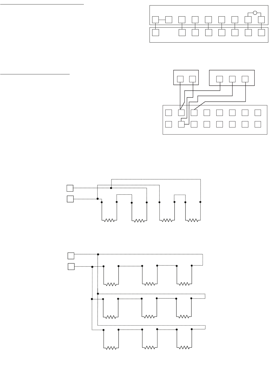
30
Staged Gas Control Option Thermistors — If the unit is
equipped with the staged gas heat option, supply-air ther-
mistors must be installed. Three supply-air thermistors are
shipped with staged gas units and are inside the heating sec-
tion. The supply-air thermistors should be located in the supply
duct with the following criteria:
• Downstream of the heat exchanger cells
• Equally spaced as far as possible from the heat
exchanger cells
• In a duct location where none of the supply-air ther-
mistors are within sight of the heat exchanger cells
• In a duct location with good mixed supply-air portion of
the unit.
SPT (Space Temperature Sensor) — For constant volume ap-
plications the ComfortLink™ controls can also be used with
T55 and T56 space temperature sensors that use a 10K ther-
mistor. The T56 sensor also has the capability for a config-
urable temperature set point offset. For variable air volume ap-
plications only the T55 sensor can be used.
Install sensor according to the installation instructions
included with accessory sensor. Locate sensor assembly on a
solid interior wall in the conditioned space to sense average
temperature.
Run wiring to the space sensor as shown in Fig. 21.
Note that when the remote sensor is used, the red jumper
wires provided must be connected from TB4 terminal 4 to 5
and TB4 terminal 5 to 1.
Both the T55 and T56 have a CCN communications port and
this should be wired to the CCN Communications TB3 board if
it is desired to have access to the CCN through the sensor. If
more than one T-55 sensor is being used and averaged, sensors
must be wired in multiples of 4 or 9 as shown in Fig. 22.
T1 T2
1
24
35
6
7
8
9
10
11
12
13
14
15
16
TH CSN
T56 SPTT55 SPT
UNIT
TB5
TB4
Fig. 20 — Field Control Thermostat Wiring
Fig. 21 — Space Temperature Sensor Wiring
RY1 Y2 W1 W2 G C X
RY1 Y2 W1 W2 G C X
FIELD-SUPPLIED THERMOSTAT
LIGHT
RC
12345 678
a48-8243
a48-6854
3
4
RED
BLK
TB5
3
4
TB5
SENSOR 1 SENSOR 2 SENSOR 3 SENSOR 4
SENSOR 1 SENSOR 2 SENSOR 3
SENSOR 4 SENSOR 5 SENSOR 6
SENSOR 7 SENSOR 8 SENSOR 9
SPACE TEMPERATURE AVERAGING (4 SENSOR APPLICATION)
SPACE TEMPERATURE AVERAGING (9 SENSOR APPLICATION)
NOTE: Use T55 sensor only.
Fig. 22 — Space Temperature Averaging Wiring
a48-6855
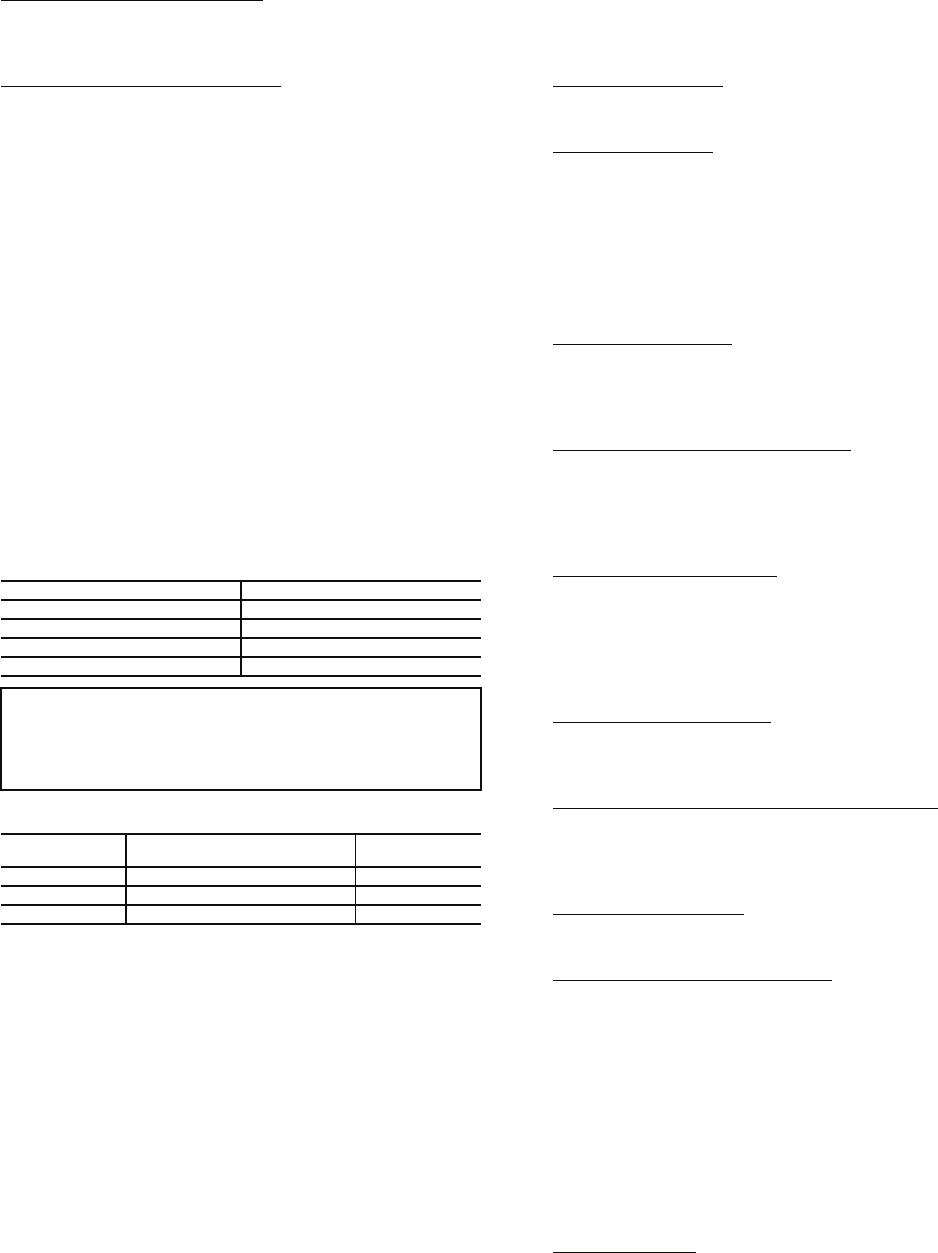
31
T58 Communicating Thermostat — Carrier also has a fully
communicating thermostat which, if used, will be wired to the
CCN communication connections on TB3 as described in the
Carrier Comfort Network® Interface section below.
Carrier Comfort Network Interface — The rooftop units can
be connected to the CCN system. The communication bus
wiring is supplied and installed in the field. Wiring consists of
shielded, 3-conductor cable with drain wire. The system
elements are connected to the communication bus in a daisy
chain arrangement. The positive pin of each system element
communication connector must be wired to the positive pins of
the system element on either side of it, the negative pins must be
wired to the negative pins, and the signal pins must be wired to
signal ground pins. Wiring connections for CCN should be
made at the TB3 terminal block using the screw terminals. The
TB3 board also contains an RJ14 CCN plug that can be used to
connect a field service computer or other CCN device tempo-
rarily. There is also an RJ14 LEN (local equipment network)
connection that is used to connect a Navigator™ device or
download software.
Conductors and drain wire must be 20 AWG minimum
stranded, tinned copper. Individual conductors must be insulat-
ed with PVC, PVC/nylon, vinyl, Teflon, or polyethylene. An
aluminum/polyester 100% foil shield and an outer jacket of
PVC, PVC/nylon, chrome vinyl, or Teflon with a minimum
operating temperature range of –20 C to 60 C (–4 F to 140 F) is
required. Table 9 lists cables that meet the requirements.
Table 9 — CCN Connection Approved Shield Cable
Table 10 — Color Code Recommendations
If a cable with a different color scheme is selected, a similar
color code should be adopted for the entire network. At each
system element, the shields of the communication bus cables
must be tied together. If the communication bus is entirely
within one building, the resulting continuous shield must be
connected to a ground at one point only. If the communication
bus cable exits from one building and enters another, the
shields must be connected to grounds at the lightning suppres-
sor in each building where the cable enters or exits the building
(one point per building only).
To connect the unit to the network:
1. Turn off power to the control box.
2. Cut the CCN wire and strip the ends of the red (+), white
(ground), and black (–) conductors. (If a different net-
work color scheme is used, substitute appropriate colors.)
3. Remove the 3-pin male plug from the base control board
in the main control box, and connect the wires as follows:
a. Insert and secure the red (+) wire to terminal 1 of
the 3-pin plug.
b. Insert and secure the white (ground) wire to termi-
nal 2 of the 3-pin plug.
c. Insert and secure the black (–) wire to terminal 3 of
the 3-pin plug.
4. Insert the plug into the existing 3-pin mating connector on
the base module in the main control box.
VAV Units with Heat — For variable air volume units that
will use heat, the variable air volume terminals should be
interlocked with the unit at TB5 terminals 1 and 2.
Demand Ventilation — The unit can be equipped with a CO2
sensor for use in demand ventilation. This can be factory
supplied and will be mounted in the return duct. It can also be
field supplied and mounted in the return duct or in the space.
Connect the field-installed 4 to 20 mA sensor to TB5 terminal
6 and 7. Do not remove the factory-installed 182-ohm resistor.
If an outdoor air quality sensor is used then it should be
wired to terminal 11 and 12 on TB6. This will require the use
of the optional controls expansion module.
Remote IAQ Override — If the control is being used with non
Carrier building management system it supports the use of the
remote IAQ override switch. This should be connected to
TB6 terminal 13 and 14. Use of this will require the optional
controls expansion module.
Remote Economizer Position Control — The ComfortLink™
controls will normally control the position of the economizer,
but it can also support field control of the economizer position
through a 4 to 20 mA signal. If this is used it should be con-
nected to TB5 terminal 6 and 7. If the signal is a 4 to 20 mA
signal then leave the 182-ohm resistor in place.
Remote Economizer Enable — If the control is being used
with other building management systems and the system will
control the enabling and disabling of the economizer free cool-
ing, this switch input can be connected to TB6 terminals 1 and
2. Note that the controls also support integrated economizer
changeover using outdoor dry bulb, differential dry bulb,
outdoor enthalpy and differential enthalpy.
Remote Occupancy Switch — For interface to other building
management systems the control also supports a switch input
for remote occupancy signals. This wiring should be connected
to terminal TB6 terminal 1 and 3.
Remote Economizer Minimum Position Control — If the
ComfortLink control is controlling the economizer, but a remote
minimum position is required, then an external 100K potentiom-
eter can be connected to TB5 terminal 6 and 7. Remove the
factory-installed 182-ohm resistor.
Smoke Sensor Interface — The ComfortLink control includes
an optional factory-installed return air smoke detector. Remote
alarm circuits can be wired to TB5 terminal 8 and 9.
Fire Shutdown and Smoke Control — The control supports
interface to fire and smoke control systems and allows for the
following system overrides from remote switch inputs.
• Fire Shutdown — Connect to TB6 terminals 8 and 9.
• Smoke Pressurization — Connect to TB6 terminal 12
and 13. This requires the use of the optional controls
expansion module.
• Smoke Evacuation — Connect to TB6 terminal 12 and
14. This requires the use of the optional controls expan-
sion module.
• Smoke Purge — Connect to TB6 terminal 12 and 15.
This requires the use of the optional controls expansion
module.
Demand Limiting — The control can also be used with demand
limiting control from remote building management systems. If a
two stage system is going to be used with Redline Limiting
where the machine is not allowed to increase load and Load Shed
where the load is decreased to a configurable limit in capacity
then these can be connected to TB6 terminals 4 and 5 and 5 and
6. This requires use of the controls expansion module.
MANUFACTURER CABLE PART NO.
Alpha 2413 or 5463
American A22503
Belden 8772
Columbia 02525
IMPORTANT: When connecting to CCN communi-
cation bus to system elements, use color coding
system for the entire network to simplify installation
and checkout. See Table 10.
SIGNAL TYPE CCN BUS CONDUCTOR
INSULATION COLOR
CCN PLUG PIN
NO.
Positive (+) RED 1
Ground WHITE 2
Negative (–) BLACK 3
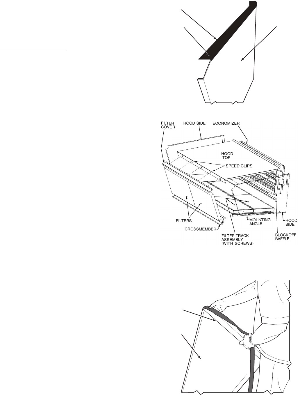
32
Step 9 — Make Outdoor-Air Inlet Adjustments
ECONOMIZER AND FIXED OUTDOOR AIR
DAMPER — Hoods are used on all units with economizer or
adjustable self-closing fixed outdoor air damper.
NOTE: If accessory power exhaust or barometric relief pack-
ages are being added to the unit, install power exhaust or baro-
metric relief before installing economizer hoods.
Economizer Hood Assembly — The economizer hood is
shipped in a package secured to the outside of the unit. The
hood assemblies must be field-assembled. The 48AW,AY units
are side supply and side return. The return duct limits access to
economizer filters from below.
The 48AJ,AK,AW,AY020-050 units have two hoods on ev-
ery unit. The 48AJ,AK,AW,AY051 and 060 units have 3 hoods
on every unit.
NOTE: Before assembly of the economizer hood, check along
the outer edges of the economizer assembly for any seal strip
protruding past the flanges. Trim the excess seal strip so that it
is flush with the economizer assembly flanges.
Perform the following procedure to assemble the economizer
hood.
1. Apply black seal strip (provided) to outside top-edge of
hood sides. Wrap seal strip over edge to cover top flange
(6 hood sides). Make sure seal strip covers screw holes.
Allow strip to overhang 1/8-in. past the end opposite the
mounting flange. See Fig. 23.
2. Assemble hood sides, top, and cross member with
gasketed screws provided. See Fig. 24.
3. Attach 15 green speed clips (provided) to hood top.
4. Apply black seal strip (provided) to mounting flanges of
hood sides being sure to cover mounting holes. See
Fig. 25.
5. Apply black seal strip (provided) to back of hood top
mounting flange. Seal strip of hood top mounting flange
must press tightly against seal strip of hood side mount-
ing flanges. See Fig. 26.
6. Add gray foam strip (provided) to cross members on bot-
tom tray. See Fig. 27.
7. Attach gray foam strip (provided) to block-off baffle on
outer face of flange. See Fig. 28.
8. Remove the screws on each end and along top of damper
assembly of unit. Remove top 4 screws on each side of
filter panel under damper assembly. Set hood assembly in
place and attach to unit using these screws.
9. Remove screws along bottom of damper assembly.
Locate and mount block-off baffle using these screws.
10. Assemble 2 filter tracks side-by-side with the assembled
ends together.
11. Attach one mounting angle to the assembled end of the
filter track. See Fig. 29.
12. Attach 9 green speed clips (provided) to hood side panels.
Engagement section of clip faces up and towards the out-
side of the hood side panels.
13. Attach remaining mounting angle to other end of the filter
track with no. 10 screws provided.
14. Place filter track assembly in bottom of hood by attaching
to hood with speed clips and gasketed screws provided.
NOTE: Be sure the filters are installed with the airflow in the
correct direction.
15. Attach black seal strip (provided) to filter cover. Seal strip
should be applied centered over the holes of the one
flange, making sure to fully cover holes and centered over
the other large flange. See Fig. 30.
16. Slide two 20 x 25-in. filters into cross members of hood
assembly. Attach filter cover over filters with screws and
speed clips provided.
HOOD SIDE
TOP
FLANGE
SEAL
STRIP
BLACK
Fig. 23 — Adding Seal Strip to Top of Hood Sides
Fig. 24 — Economizer Hood Assembly
(Right Side/Center Economizer Hood Shown)
HOOD SIDE
MOUNTING
FLANGE
Fig. 25 — Adding Seal Strip to Sides of Hood Top
Mounting Flange
a48-8498
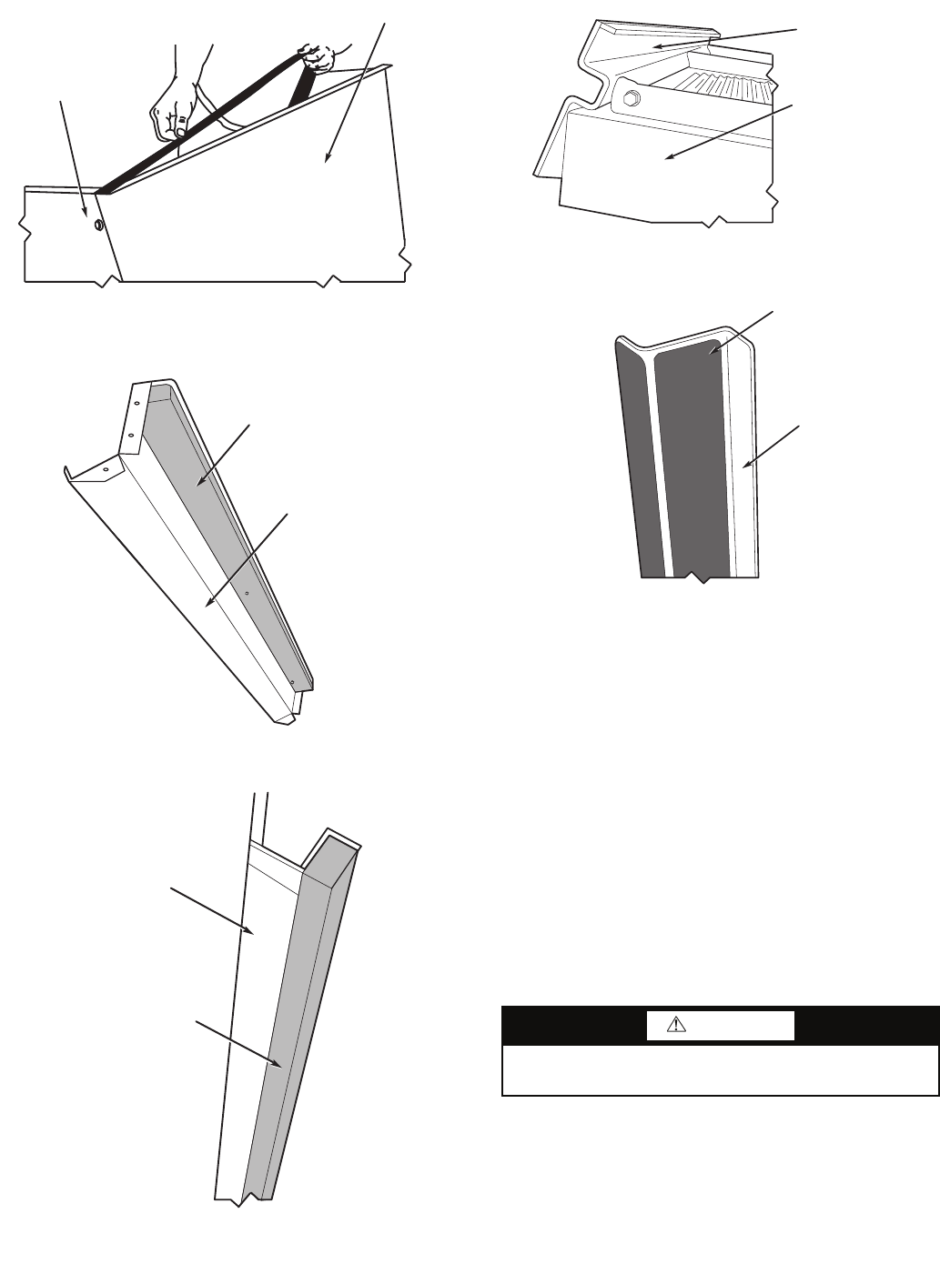
33
Step 10 — Position Power Exhaust/Barometric
Relief Damper Hood — All units are shipped with the
hoods folded inside the unit in a shipping position. For 48AJ,
and AK units the hood must be tilted out once the unit is in-
stalled. On 48AW, AY units, (designed for horizontal supply
and return) the assemblies will have to be relocated to return
ductwork. See Fig. 31 for dimensions and details.
All electrical connections have been made and adjusted at
the factory. The power exhaust blowers and barometric relief
dampers are shipped assembled and tilted back into the unit for
shipping. Brackets and extra screws are shipped in shrink wrap
around the dampers. If ordered, each unit will have 4
(48AJ,AK,AW,AY020-050 units) or 6 (48AJ,AK,AW,AY051
and 060 units) power exhaust blowers and motors or baromet-
ric relief dampers.
1. Remove 9 screws holding each damper assembly in
place. See Fig. 32. Each damper assembly is secured with
3 screws on each side and 3 screws along the bottom.
Save screws.
2. Pivot each damper assembly outward until edges of
damper assembly rest against inside wall of unit.
3. Secure each damper assembly to unit with 6 screws
across top (3 screws provided) and bottom (3 screws
from Step 1) of damper.
4. With screws saved from Step 1, install brackets on each
side of damper assembly.
5. Remove tape from damper blades.
CAUTION
Be careful when tilting blower assembly. Hoods and blow-
ers are heavy and can cause injury if dropped.
MOUNTING ANGLE
FILTER TRACK
ASSEMBLY
Fig. 29 — Mounting Angle Attached
to Filter Track Assembly
a48-8499
BLACK SEAL STRIP
(CENTERED)
FILTER COVER
Fig. 30 — Attaching Seal Strip to Filter Cover
48-1110
HOOD TOP
HOOD SIDE
CROSS MEMBER
GRAY FOAM STRIP
Fig. 26 — Adding Seal Strip to Back of Hood Top
Mounting Flange
Fig. 27 — Adding Foam Strip to Cross Member
48-1104
48-1105
BLOCKOFF BAFFLE
GRAY FOAM STRIP
Fig. 28 — Adding Seal Strip to Block-Off Baffle
a48-4328
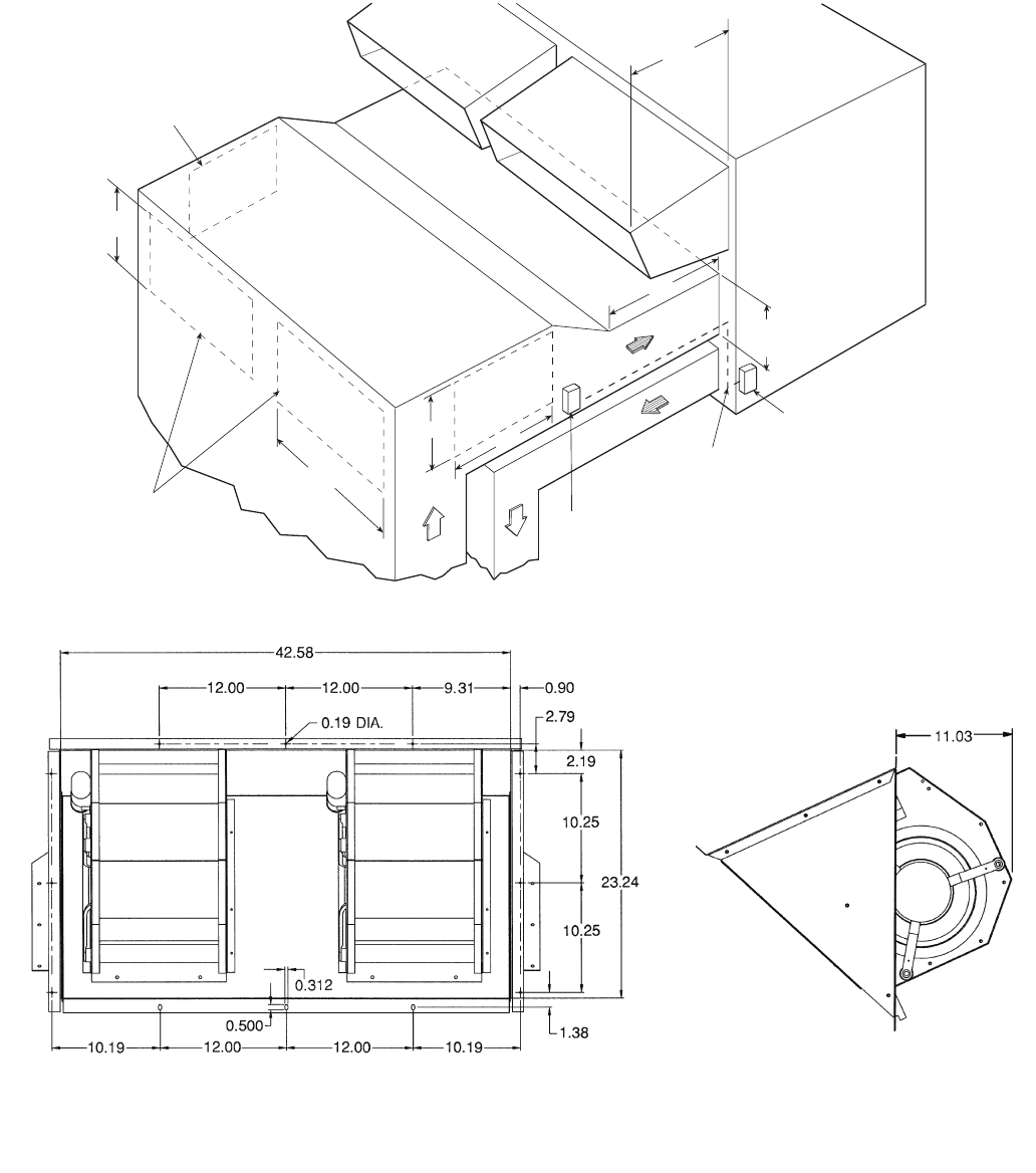
34
Step 11 — Route VAV Static Pressure Sensors
VAV DUCT PRESSURE TRANSDUCER — The VAV duct
pressure transducer (VAV inverter pressure transducer) is locat-
ed behind the filter access door on the lower inner panel. See
Fig. 33. A section of field-supplied 1/4-in. plastic tubing must
be run from the high pressure tap on the differential pressure
switch and connected to a field-supplied tap in the supply-air
duct. The tap is usually located 2/3 of the way out on the main
supply duct. Remove plug button in panel to route tubing.
VAV BUILDING PRESSURE TRANSDUCER — The VAV
building pressure transducer (modulating power exhaust pres-
sure transducer) is located behind the filter access door on the
lower inner panel. See Fig. 33. A section of field-supplied
1/4-in. plastic tubing must be run from the high pressure tap on
the differential pressure switch to the conditioned space. The
pressure tube must be terminated in the conditioned space
where a constant pressure is required. This location is usually
in an entrance lobby so that the building exterior doors will
open and close properly. Remove plug button in panel to route
tubing.
The low pressure tap is factory-routed to the atmosphere.
For a positive-pressure building, route the high tap to building
air and low tap to atmosphere. For a negative-pressure
42.56”
42” MIN.
S/A
R/A
ECONOMIZER
HOOD
ECONOMIZER
HOOD
J BOX
PLENUM RATED
CABLE
(FIELD SUPPLIED)
12.94
(UNIT
OPENING)
NOTE: 020-050 SIZES SHOWN (2 POWER EXHAUST FANS).
SIZES 051 AND 060 HAVE 3 POWER EXHAUST FANS. ALL
UNIT SIZES HAVE THE SAME SIZE POWER EXHAUST.
“END #2”
“END #1”
ALTERNATE
LOCATION
(END)
23.28”
TYP
42.62
TYP
LOCATION
BAROMETRIC RELIEF
OR POWER EXHAUST
“SIDE #2”
23.28”
“SIDE #1”
42.62”
J BOX
R/A S/A
Fig. 31 — Power Exhaust Relocated to Side Return Duct
a48-8244
NOTES:
1. Unless otherwise specified, all dimensions are to outside of part.
2. Dimensions are in inches.
3. On 48AW,AY units, accessory barometric relief or power exhaust must be mounted in the field-supplied return ductwork.
Fig. 32 — Barometric Relief Damper and Power Exhaust Mounting Details
a48-3808
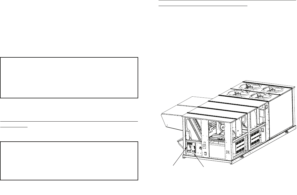
35
building, route the high tap to atmosphere and the low tap to
building air.
Step 12 — Install All Accessories — After all the
factory-installed options have been adjusted, install all field-
installed accessories. Refer to the accessory installation instruc-
tions included with each accessory.
The 48A Series units have a large number of factory-
installed options which were previously available only as
accessories. Some of the available options can also be installed
in the field if needed. In most cases the units have been
pre-wired so that the accessories can be easily installed.
Instructions are shipped with each accessory. Configuration of
the controls for these accessories as well as the factory-installed
options can be found in the Controls, Start-Up, Operation,
Service and Troubleshooting Book. The following is a list of
some of the common accessories:
• Thermostats and space temperature sensors
• LP (liquid propane) conversion kit
• Accessory barometric relief damper
• Accessory power exhaust
• Non-modulating to modulating power exhaust
• Condenser coil hail guards
• Outdoor humidity sensor (used for economizer enthalpy
changeover)
• Return air humidity sensors (used for economizer
differential enthalpy changeover)
• Return air smoke detector
• Controls expansion module (used for interface to build-
ing management systems, not typically needed on
system with the Carrier Comfort Network® [CCN] sys-
tem)
• Plugged filter sensor
• Motormaster® V low ambient head pressure control
Step 13 — Field Modifications
DUCTWORK
Bottom Return Units (48AJ and AK) Field-Modified for
Side Return — The 48AJ and AK units with bottom return air
connections may be field-modified to accommodate side return
air connections.
Conversion to horizontal return requires that the bottom
return openings of the unit must be sealed with airtight panels
capable of supporting the weight of a person. The return
ductwork connection locations on the side of the unit are higher
than normal (31-in. high). Unit-mounted power exhaust or
barometric relief cannot be used because of return air ductwork
will cover the power exhaust or barometric relief installation
locations. Power exhaust or barometric relief may be installed
in the return air ductwork.
To convert the unit, perform the following:
1. Seal the bottom return openings of the unit with airtight
panels capable of supporting the weight of a person.
2. Remove the panels located below the economizer
outdoor-air dampers. These openings will be used for the
return-air ductwork. There are 2 panels on 48AJ,AK020-
050 units. There are 3 panels on 48AJ,AK051 and 060
and units. These openings are normally used for power
exhaust or barometric relief.
3. Run the return air ductwork up to the openings. One
single duct is recommended to connect to the unit over
the return air openings. See Fig. 34. The return duct must
incorporate a minimum 3/4-in. flange for connection to
the unit cabinet. The unit does not have duct flanges for
this conversion.
Side Supply and Return Units (48AW,AY) with Field-
Installed Power Exhaust in Return Duct — Space must be
available in the return duct to mount the power exhaust fan
(gravity relief) modules. Dimensions and suggested locations
are shown in Fig. 34. These instructions are a guideline and not
a comprehensive procedure. The design contractor must pro-
vide some design initiative.
The wiring harness that is provided with the power exhaust
accessory is not long enough for the fan modules to be mount-
ed in the return air duct. Field-supplied wiring must be spliced
into the harness. Use a junction box at each splice. The wiring
may be run in the return duct, or externally in conduit. A ser-
vice access panel will be needed near each power exhaust fan.
IMPORTANT: Carrier recommends the installation of
field-fabricated wind baffles on all vertically oriented
condenser coils when operating in environments with
prevailing winds of more than 5 MPH and where tem-
peratures drop below 32 F. See the Motormaster
accessory installation guide for instructions.
IMPORTANT: The following section is a guideline and not
a comprehensive procedure to field modify the units. The
installing contractor must provide some design initiative.
Field-conversion is complex and is not recommended.
Units with electric heat must not be converted because of
potential heating mode operating problems.
AUXILIARY
CONTROL BOX
PRESSURE TRANSDUCERS
(INSIDE OF PANEL)
Fig. 33 — Pressure Transducer Locations
a48-6976
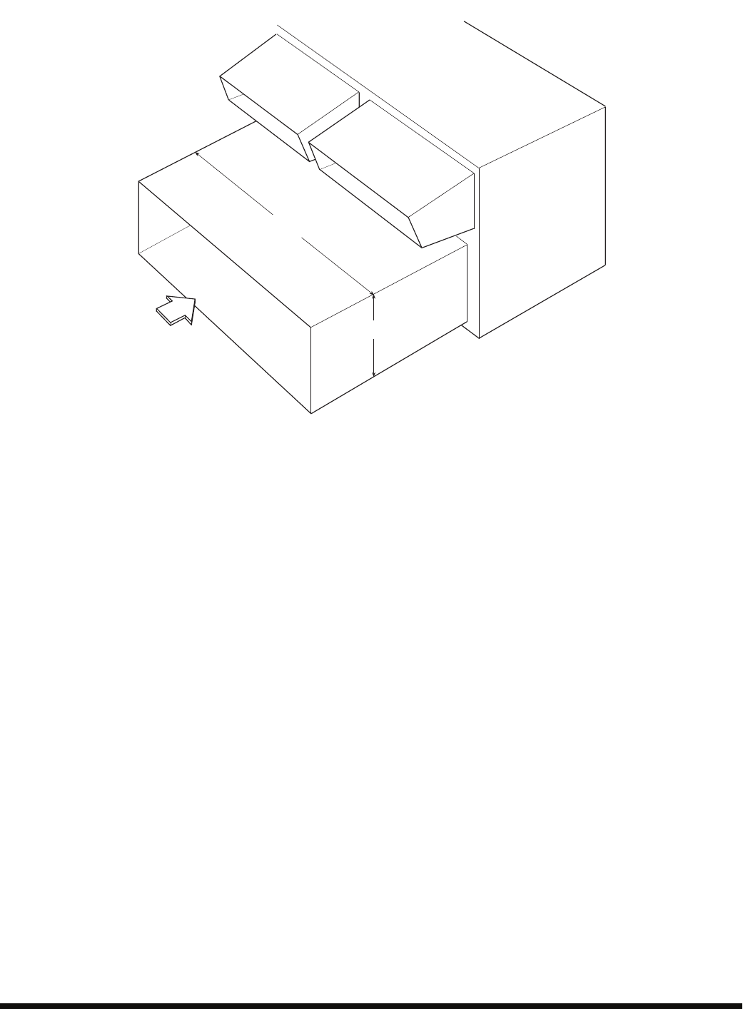
Manufacturer reserves the right to discontinue, or change at any time, specifications or designs without notice and without incurring obligations.
Catalog No. 04-53480067-01 Printed in U.S.A. Form 48A-7SI Pg 36 8-09 Replaces: 48A-5SI
Copyright 2009 Carrier Corporation
31.25”
INSIDE
RA
97.78” (020-050), 150.47” (051 AND 060)
INSIDE DIMENSION
Fig. 34 — Side Return Air Conversion
a48-8245
