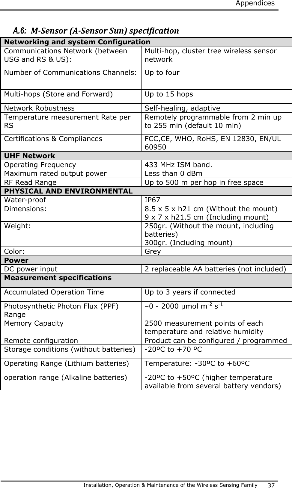
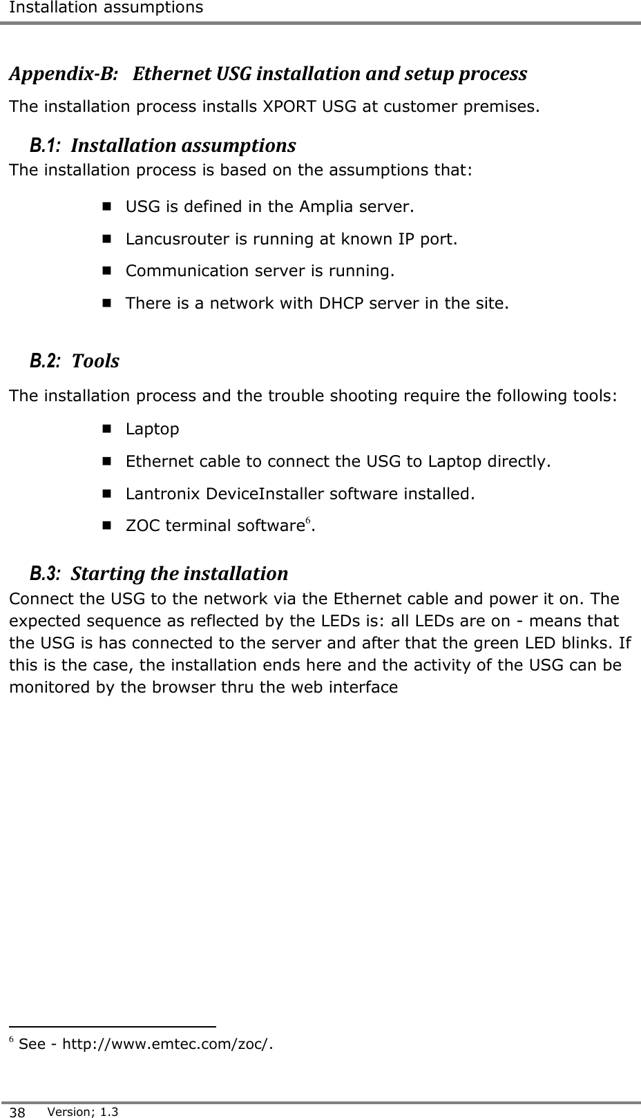
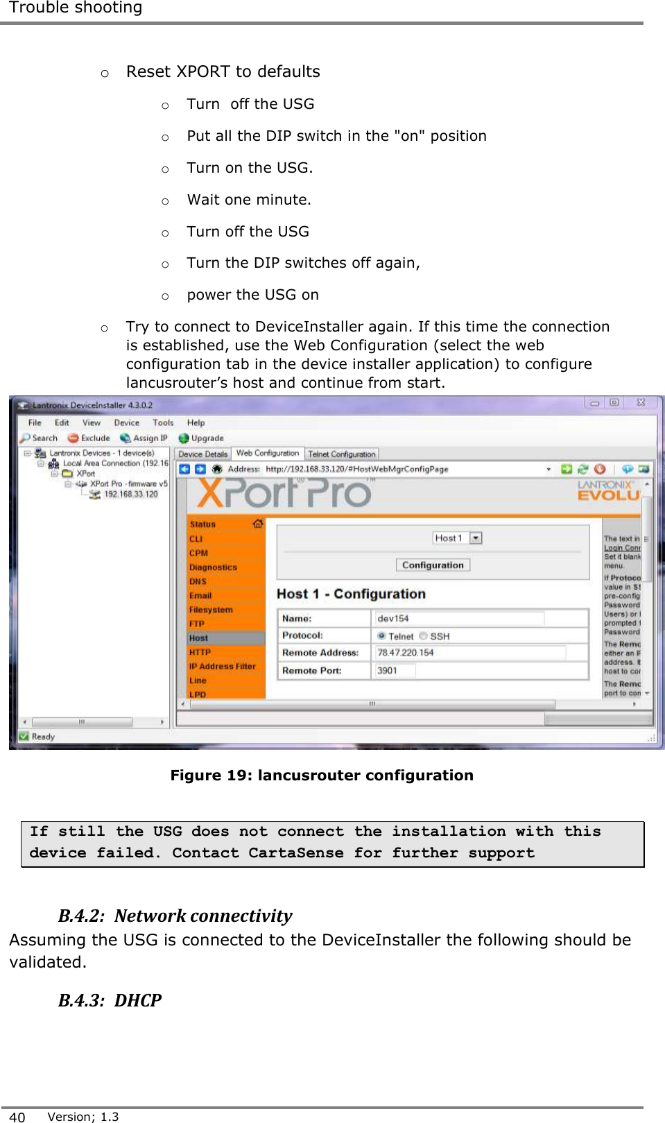
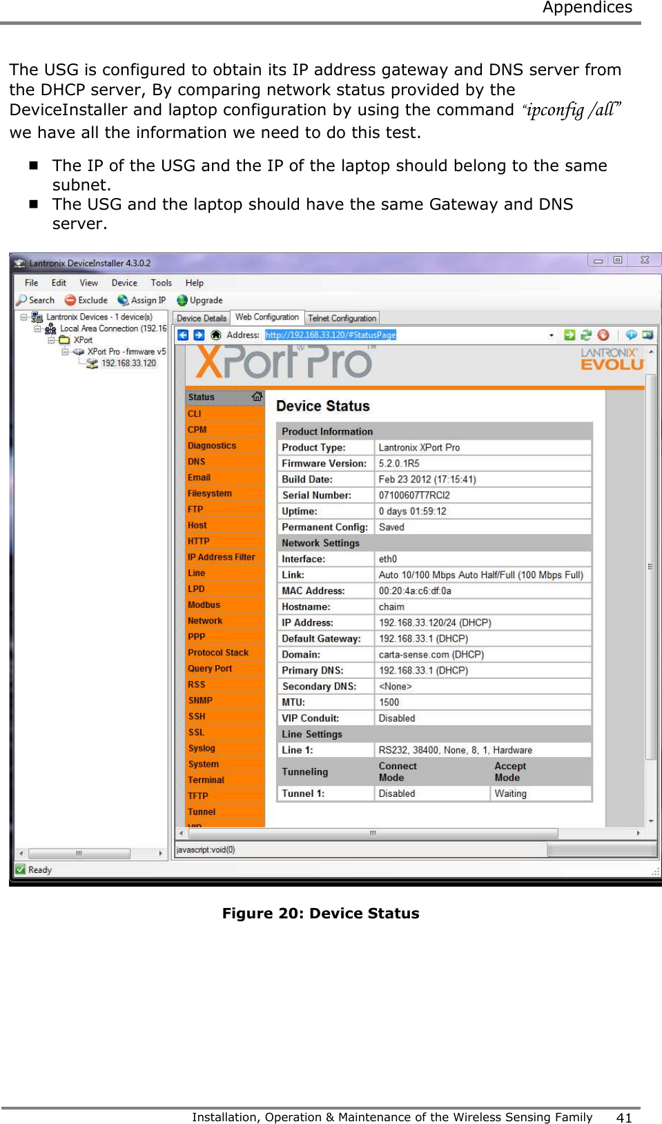
CartaSense MSENSOR01 Wireless sensor User Manual
CartaSense Ltd. Wireless sensor
UserManual.wiki
>
CartaSense
>
MSENSOR01 User Manual
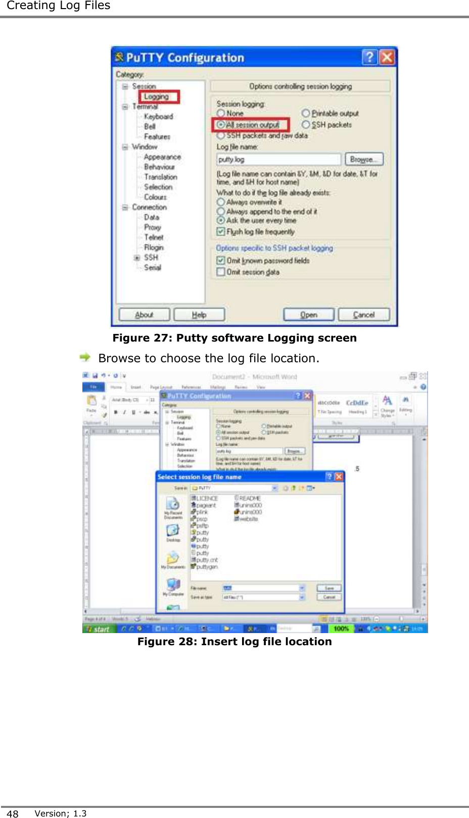
User manual
Navigation menu
Upload a User Manual
Namespaces
Wiki Guide
HTML
PDF
Info
Views
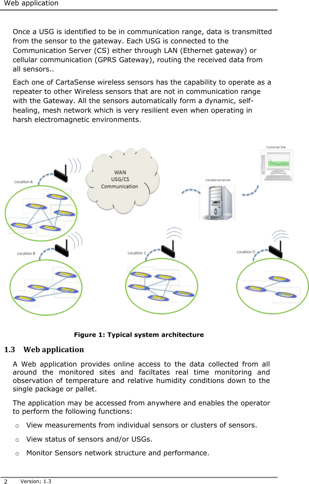
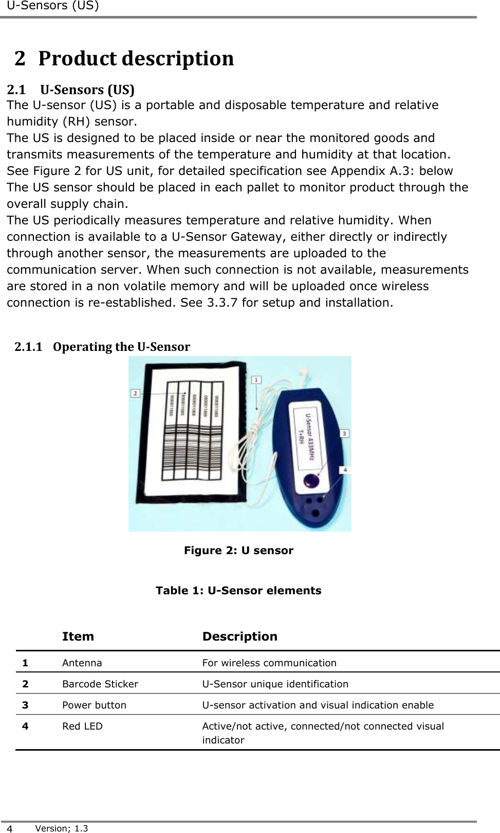
User Manual
Discussion / Help
Navigation