Carttronics 00004 Caster Reset Controller User Manual RX01
Carttronics LLC Caster Reset Controller RX01
user manual

RX01 USER MANUAL
Table of Contents
Product Description ............................................................................................................ 1
Settings ................................................................................................................................ 1
Join A Network ................................................................................................................... 2
P
RODUCT
D
ESCRIPTION
The RX01 Reset Controller is a wireless remote device for use in retail asset management applications.
The reset controller leverages the industry wireless standard IEEE 802.15.4 to seamlessly integrate with
other retail solutions. With RX01 Reset Controller, security of retail carts has never been more dependable.
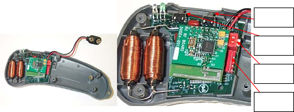
Figure 1a: RX01 Assembly. Figure 1b: RX01 Mother and Daughter Assembly.
Lock Button,
SW 2.
Unlock
Button, SW1.
Future options
switch, SW4.
Option switch,
SW3.
S
ETTINGS
Properly assembled, the RX01 radio board will connect to a controller main board which can be seen in
figure 1a. The locations of the DIP switches and the LOCK and UNLOCK buttons are shown in figure 1b.
The controller determines its personality from the six DIP options switches, located on the controller main
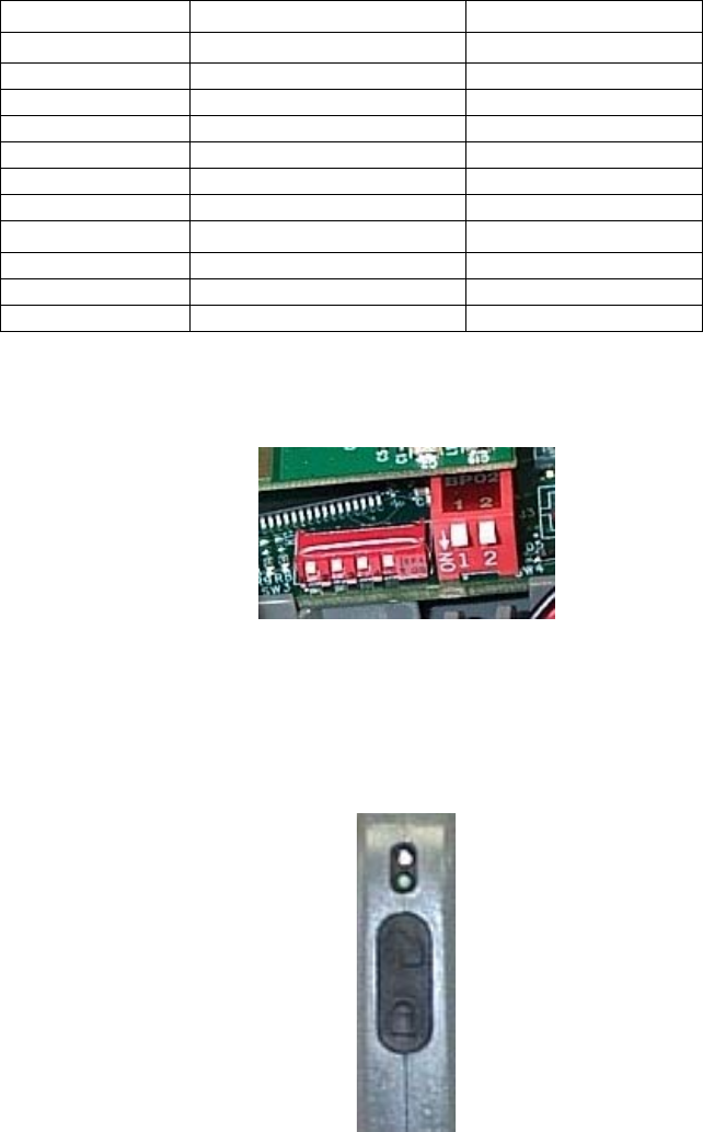
board; SW3 and SW 4, shown in figure 1b. Figure 2 shows the four switches at SW3 and the two switches
at SW4 in the OFF position. Select the appropriate DIP settings for desired functionality using the
following table:

DIP Switch
Operation
SW3
ON OFF
1 Standard Locking Signal Extra Locking Signal
2 Standard Unlocking Signal 4.0 Unlocking Signal
3 not used (off) not used (off)
4 not used (off) not used (off)
SW4
ON OFF
1 not used (off) not used (off)
2 not used (off) not used (off)
Table 1: DIP Switch Options.
Figure 2: SW3 and SW4 DIP switch (All switches are in the OFF postion).
J
OIN
A
N
ETWORK
The following procedure outlines how to join the RX01 radio board to a system network.
Figure 3: Unlock (SW1) & Lock buttons (SW2).
Join Operation
Step 1: Properly place the RX01 device in its mounting station. Once mounted, hold the Lock
button, SW2, for two seconds or until the green LED flashes twice in rapid succession. This
signals a successful connection to the network.

FCC ID: USH00004
IC: 6834A-00004
This device complies with Part 15 of the FCC Rules. Operation is subject to the
following two conditions: (1) This device may not cause harmful interference, and (2)
This device must accept any interference received, including interference that may cause
undesired operation.
WARNING
Any changes or modifications made to the RX01 not aforementioned in the User Manual, or expressly approved
by the RX01 manufacturer, will void the user’s authority to operate the equipment.