Carvin Dcm200L Owners Manual DCM200 12_03
2014-07-19
: Carvin Carvin-Dcm200L-Owners-Manual carvin-dcm200l-owners-manual carvin pdf
Open the PDF directly: View PDF ![]() .
.
Page Count: 4
CARVIN ENGINEERING DATA OPERATING MANUAL
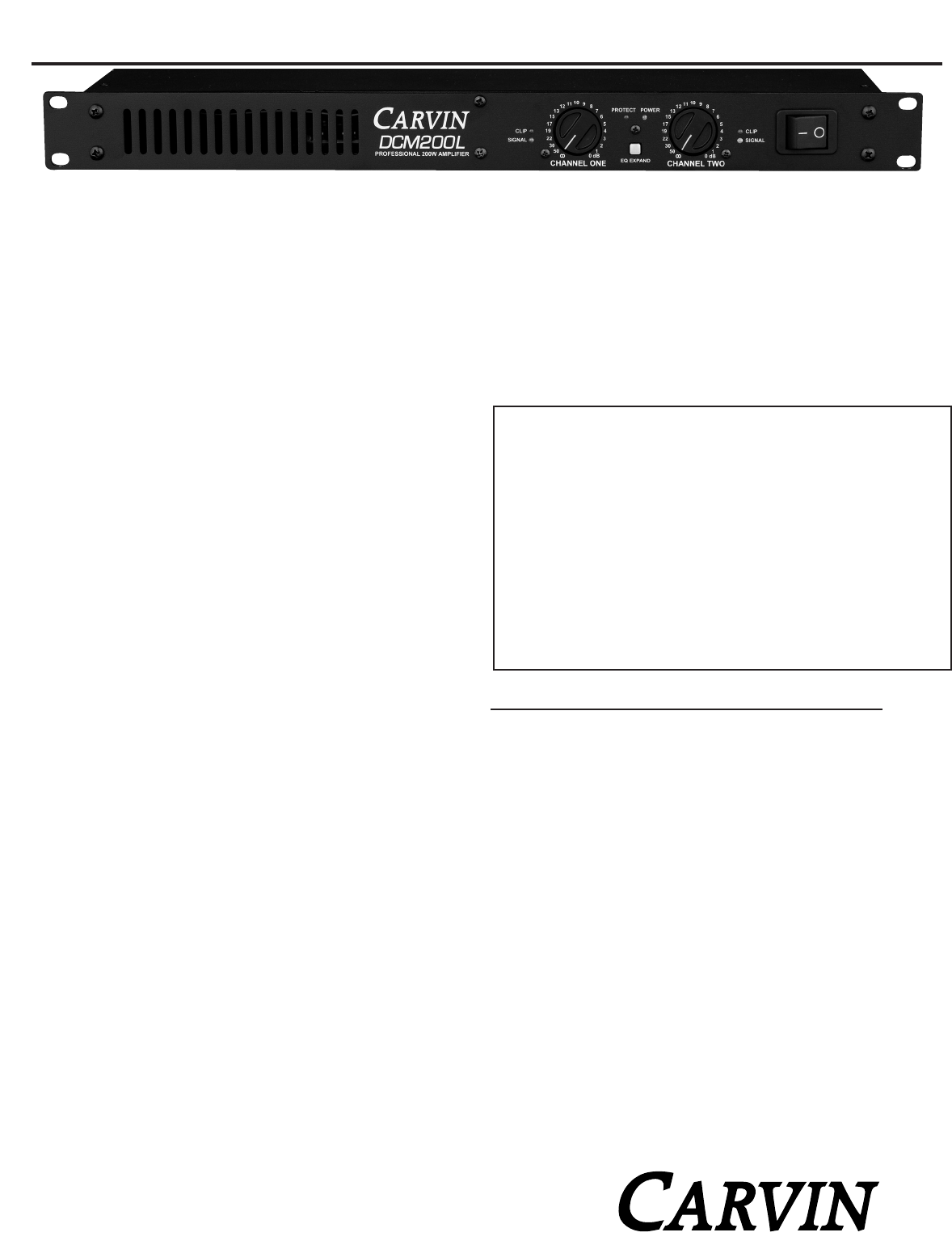
The DCM200L professional amp is designed utilizing Carvin’s years of expe-
rience in power amp technology. The switchmode power supply not only
takes the weight of this amp down to a mere 4 Lbs, but it also provides a
full 100w per channel at 8 ohms! This amp is also compatible with 120/240v
AC power so it can be used worldwide. It meets and exceeds every stan-
dard for professional amplification.
PURE—TRANSPARENT SOUND
Carvin considers the sound of an amp equally important as its reliability.
To insure pure, uncolored sound, we designed one of the fastest respond-
ing power amps on the market today. High slew rates deliver superb tran-
sient response. High frequencies are transparent and open—even at high
levels. Linear feedback circuits reduce distortion to near the theoretical zero
limit preventing any type of harshness which would lead to ear fatigue. The
DCM200L amp delivers flat, transparent, unaltered sound—especially impor-
tant to the studio user. These amps are designed to deliver non-stop, con-
tinuous power and are completely protected from heat and short circuits.
ULTRA RUGGED FOR TOURING
Every chassis is made from heavy-duty 16 gauge aluminum that is light-
weight and prevents rust. All internal cabling is neatly tied and harnessed.
Heavy-duty power switches, recessed knobs & machined aluminum front
panels all give the DCM amps a “tank-like” ability to handle rough, tour-
ing transport.
LOSE THE WEIGHT...NOT THE PERFORMANCE
Switchmode power supplies automatically adjust to the AC voltage in your
country. External transformers are not required. This technology also elim-
inates the weight associated with old fashioned transformers. The efficiency
of switchmode technology is also another benefit. The DCM200L will use
AC power efficiently with very little power wasted, this means it will func-
tion to its full capacity without using more AC power than necessary. This
“green” efficiency is also a benefit when using the amp with a gas powered
generator. Generators can vary in their ability to sustain a constant AC volt-
age, but a DCM200L will function without a problem on a small portable
generator as it can function using 90-250VAC 50-60Hz. Switchmode power
supplies are also known for reducing stray magnetic fields eliminating hum
& noise. This is especially important for the recording industry.
For your records, you may wish to record the following information.
Serial No._____________________ Invoice Date_______________
DCM200L POWER AMP SPECIFICATIONS:
Output Power
(Stereo, both channels driven with REAR IMPEDANCE SWITCH IN)
8Ω, 1kHz, < 0.5% THD 60/60 Watts
4Ω, 1kHz, < 0.5% THD 100/100 Watts
Minimum Impedance 4 ohms per channel
(Stereo, both channels driven with REAR IMPEDANCE SWITCH OUT)
8Ω, 1kHz, < 0.5% THD 100/100 Watts
4Ω, 1kHz, < 0.5% THD -----------
Minimum Impedance 8 ohms per channel
(BRIDGE MONO with REAR IMPEDANCE SWITCH IN)
8Ω, 1kHz, < 1% THD 200 Watts
16Ω, 1kHz, < 1% THD 120 Watts
(BRIDGE MONO with REAR IMPEDANCE SWITCH OUT)
8Ω, 1kHz, < 1% THD ------------
16Ω, 1kHz, < 1% THD 200 Watts
THD
20-20kHz < 0.1%
(8Ωtypical) < 0.05%
Frequency Response ±0.5 dB, 20 Hz to 20 kHz
Input Impedance > 20kΩBalanced or Unbalanced
Damping Factor >400
Sensitivity (@ 4ohms) 1.0 Vrms
Output Noise -102 dBm
Power Requirement 90-240 VAC
Dimensions 1 3/4” High x 19” Wide x 9” Deep
Weight (Net) 4lbs.
76-00150 1109
800 854-2235 www.carvin.com
DCM200L POWER AMP
FRONT PANELS & CONNECTING UP
The DCM Series feature front panel signal, clip and protect LEDs which let you mon-
itor the status of the amp. Both channels use precision level controls allowing you to
see your settings at a glance. Balanced 1/4 phone & XLR input jacks are used to elim-
inate hum & noise. Speaker outputs feature 1/4” jacks and heavy-duty binding posts.
A GROUND switch removes the chassis ground from the XLR input, a PARALLEL
input switch connects the inputs of both channels together eliminating Y connectors
and allowing amp patching in multiple amp systems. An impedance switch and
BRIDGE switch delivers optimal power to your speakers.
RECEIVING INSPECTION—read before getting started
INSPECT YOUR UNIT FOR ANY DAMAGE which may have occurred during shipping.
If any damage is found, please notify the shipping company and CARVIN immediately.
SAVE THE CARTON & ALL PACKING MATERIALS. In the event you have to re-ship your unit,
always use the original carton and packing material. This will provide the best possible pro-
tection during shipment. CARVIN and the shipping company are not liable for any damage
caused by improper packing.
SAVE YOUR INVOICE. It will be required for warranty service if needed in the future.
SHIPMENT SHORTAGE. If you find items missing, they may have been shipped sepa-
rately. Please allow several days for the rest of your order to arrive before inquiring.
RECORD THE SERIAL NUMBER on the enclosed warranty card or below on this manual
for your records. Keep your portion of the card and return the portion with your name
and comments to us.
USA customers register online at: www.carvin.com/registration
All other countries register online at: www.carvinworld.com/registration
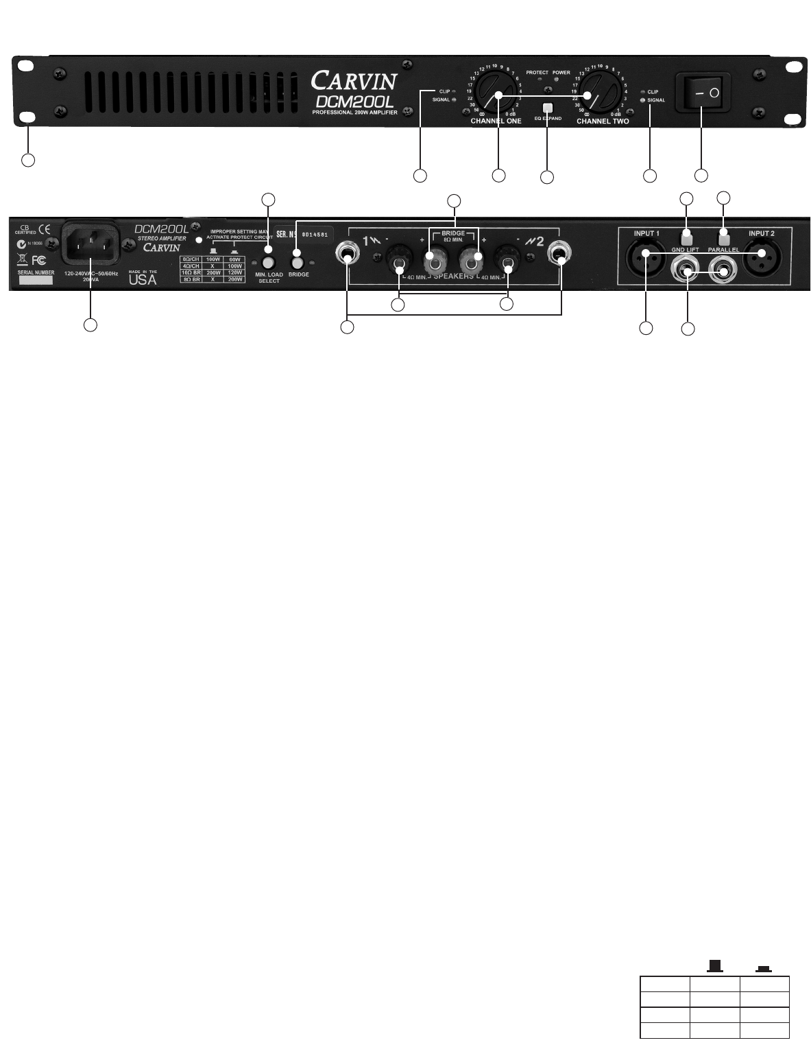
FRONT PANEL
1. MOUNTING
The rack mounting holes are designed on ISO standard spacing. Four
10-32 x .5” phillip machine screws are normally used to secure the amp.
Rear support brackets are not required.
2. POWER SWITCH
Check the power amp connections and verify the AC line power source
before engaging the POWER switch. The yellow LED unmistakably indi-
cates that all circuits are properly powered up. This color was chosen so
the operator could see the red protect indicator from a distance.
3. CHANNEL LEVEL CONTROL
A precision input LEVEL attenuator is used to adjust the volume levels.
To deliver the amps full power without reducing headroom of the signal
source, the level controls should be turned up full.
4. CHANNEL SIGNAL INDICATOR
The green SIGNAL LED indicators will illuminate when there is a signal pass-
ing to your speakers (-30dBM).
5. CHANNEL CLIP INDICATOR
The red CLIP LED indicators will start to flash when each channel has
reached its maximum output. Occasional flashing caused by lower bass
frequencies is OK. However, consistent flashing caused from higher
frequencies may damage high frequency drivers (excessive distortion).
This does not cause damage to the amp.
6. EQ EXPAND SWITCH
When set to the ‘in’ position this circuit will cut the mids by -4dB at
1KHz. This works well as a loudness contour when operating at low volume
levels or adds tone when using it in a bass or guitar rack. When set to
the ‘out’ position it provides a flat, normal response. Try it both ways
and set as desired.
REAR PANEL
7. XLR CHANNEL INPUTS
For most professional applications, use the XLR balanced input. This
will help to reduce hum and allow for longer cable runs from your signal
source (mixer, etc). Because this is a balanced input, the gain will be 6
dB higher than using a non balanced 1/4” input. XLR pin configuration:
Pin 1: Grounded through the GROUND LIFT switch, Pin 2: positive Bal.
signal and Pin 3: negative Bal. signal.
8. CHANNEL 1/4” PHONE JACK INPUT
These 1/4” TRS phone jacks are designed to receive either balanced or
unbalanced input signals. Balanced signals coming into this jacks should
be wired with the connector’s tip going to signal + and the connector’s
ring to signal –. The connector’s sleeve is then tied to ground through
the GROUND LIFT switch–.
9. SPEAKER OUTPUTS
The standard 1/4” SPEAKER jacks are used for most applications. Turn
the amp off before connecting your speakers.
10. SPEAKER BINDING POSTS
For heavy-duty speaker connections, use the rear BINDING POSTS to con-
nect your speakers. Wire sizes up to 7 gauge (50 amps) can be inserted
into the binding posts “side holes”. Larger cable can be used with “banana”
plugs which plug into the ends of the binding post (remove colored caps).
Binding posts are spaced on ISO standards. Use the two center RED bind-
ing posts for BRIDGE speaker connections (see 11 BRIDGE MODE).
11. BRIDGE MODE
The DCM200L can be operated in bridge mode if you require a high pow-
ered mono (single channel) amp. With your amp off, push in the rear
BRIDGE switch after you have made your speaker connections to the rear
center RED binding posts (ch 1 is + and ch 2 is -). No other speaker jack
or binding post can be used at the same time!”. The INPUT and LEVEL
is handled by channel 1. Channel 2 is non-operational. The minimum
speaker impedance is 8 ohms. CAUTION: The power developed by bridg-
ing your amp can destroy speakers!
12. PARALLEL OR “Y” INPUTS
The rear PARALLEL switch allows you to drive both channels from either
input. All signals entering any input will be available on both channels.
This eliminates Y adapter cables. This feature is used to “daisy chain”
one piece of equipment to another. Just plug into the unused INPUT (1/4”
or XLR) and it will become an output for other equipment.
13. INPUT GROUND LIFT
Many times sound systems are connected in such a manner to cause a
grounded loop with the inputs that result in audible hum. The input GND
LIFT (1/4” & XLR) switch on the rear panel will help eliminate this prob-
lem. If not, another way to eliminate ground loops is to install a “line match-
ing” transformer between the amplifier input and the signal source and
cut the ground wire to PIN 1.
14. AC POWER
The internal Switchmode power supply is designed to run on 120V 60
Hz or 240V 50 Hz. The voltage range is 90V to 250V. Never defeat the
grounded connection or electrocution may result!
15. IMPEDANCE SWITCH
Set this switch to correspond to the min impedance of your speakers.
Note: That this amp is capable of 100w
per channel at 8 ohms. Be certain that
the speakers can handle this amount of
power.
2
6
1
34
5
FRONT & REAR PANEL CONTROLS
78
9
10 10
11 12
13
14
4Ω/CH
8Ω/CH
16Ω BR
8Ω BR
100W 75W
100W
X
200W 150W
X200W
15
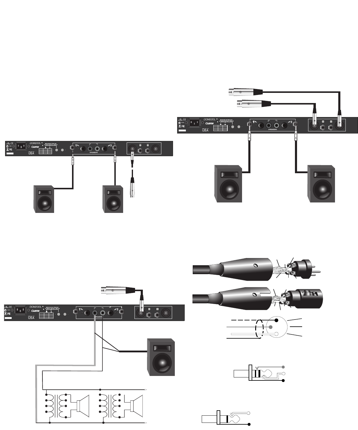
CONNECTING THE SYSTEM
The following diagrams illustrate typical connections. Although these illustrations show
XLR’s for inputs and 1/4” plugs for outputs, a variety of alternative connectors are available.
For most stage setups, mono (not stereo) is recommended. The reason for this is the
audience on the left will not hear the same program material on the right if the program is
done in true stereo.
INPUT CONNECTIONS
The preferred method of connecting input signals is with balanced XLR’s (two conductors
plus a shield wire such as Carvin professional XLR cables). Balanced input signals provide
the highest gain and best noise rejection. 1/4” stereo cables are also capable of providing
balanced input by using a stereo plug (tip-positive, ring-negative & sleeve-ground). Not all
sources provide balanced outputs. If this is the case, standard 1/4” input cables work fine
with cable lengths under 25 feet (single conductor plus shield) providing there is no ground
loop in the system.
SERIAL NUMBER
PAR ALL ELGND LIFT
INPUT 1 INPUT 2
BRIDGE
120-240VAC~50/60Hz
225VA
MIN. LOAD
SELECT
BRIDGE
STEREO AMPLIFIER
4/CH
8/CH
16 BR
8 BR
100W 75W
100W
X
200W 150W
X200W
4 MIN. 8 MIN. 4 MIN.
Use 16 guage or heavier
Non shielded cables (PH50).
Plug into the 1/4" speaker jacks
or strip and insert into speaker
Binding Post (Red+ Black-)
Ch 2 Speaker
Ch 1 Speaker
BRIDGE switch
must be OFF (OUT).
PARALLEL switch
must be (IN)
TYPICAL STEREO (BIAMP) SETUP
SERIAL NUMBER
PARALLELGND LIFT
INPUT 1 INPUT 2
BRIDGE
120-240VAC~50/60Hz
225VA
MIN. LOAD
SELECT
BRIDGE
STEREO AMPLIFIER
4/CH
8/CH
16 BR
8 BR
100W 75W
100WX
200W 150W
X200W
4 MIN. 8 MIN. 4 MIN.
INPUT 1
Use 16 guage or heavier
Non shielded speaker cables.
Plug into the 1/4" speaker jacks
or strip and insert into speaker
Binding Post (Red+ Black-)
Use a XLR or 1/4" 2 or 3 cond. shielded cables
Full Range
(Lo Freq. Bi-Amp)
Woofer System
Full Range
(Hi Freq. Bi-Amp)
Horn System
(Hi Freq. Bi-Amp)
(Lo Freq. Bi-Amp)
Ch 1 Left
Ch 2 Right
SPEAKER CONNECTIONS
There are two 1/4” speaker jacks available for speaker connections (one for each channel).
Additionally, there are two pairs of binding posts that not only allow for high current con-
nections to speakers but are also used for “bridging” the amps output (see rear panel sec-
tion 14 & 15). Use heavy gauge wire for all speaker connections (no lighter than 16 gauge
up to 50’). Caution: Never use shielded cable (microphone or instrument input cable) to
connect speakers. These cables will not handle the required current and may cause
damage.
SERIAL NUMBER
PARALLELGND LIFT
INPUT 1 INPUT 2
BRIDGE
120-240VAC~50/60Hz
225VA
MIN. LOAD
SELECT
BRIDGE
STEREO AMPLIFIER
4/CH
8/CH
16 BR
8 BR
100W 75W
100W
X
200W 150W
X200W
4 MIN. 8 MIN. 4 MIN.
INPUT 1
Use a XLR or 1/4" 2 or 3 cond. shielded cables
Activate the BRIDGE switch
(IN). Control the level by Ch 1
( Ch 2 does not function.
70V Distribution System:
"TAP" Wattage of transformer
(can vary from diagram)
divided by total wattage
of Amp = Number of
transformer/speaker(s)
that can be hooked up.
Single speaker or
system connected
in BRIDGE mode.
Minimum imp. 8
+
16
8
4
C
15w
7w
3w
1w
C
+
16
8
4
C
15w
7w
3w
1w
C
OR
TYPICAL MONAURAL SETUP
TYPICAL BRIDGED SETUP
SHIELD
-NEG.
3
1
2
+POS.
SHIELD
-NEG. 3
1
2
+POS.
GND
- SIGNAL (BAL.)
+ SIGNAL (BAL.)
BALANCED MIC/LINE XLR CABLES
1
2
3
INTERRUPT (PATCH)
STEREO OR BALANCED SIGNAL LINE
SHIELD (GROUND)
+ SIGNAL (RETURN)
- SIGNAL (SEND)
SPEAKER OR SIGNAL LINE CABLE
(Unshielded) (Shielded)
(Shielded)
SHIELD (GROUND)
+ TIP (HOT)
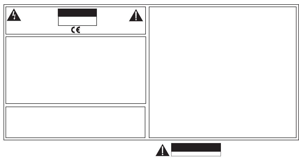
CAUTION
RISK OF ELECTRIC SHOCK
DO NOT OPEN
SAFETY INSTRUCTIONS (EUROPEAN)
The conductors in the AC power cord are colored in accordance with the following code.
GREEN & YELLOW—Earth BLUE—Neutral BROWN—Live
U.K. MAIN PLUG WARNING: A molded main plug that has been cut off from the cord is
unsafe. NEVER UNDER ANY CIRCUMSTANCES SHOULD YOU INSERTA DAMAGED
OR CUT MAIN PLUG INTO A POWER SOCKET.
IMPORTANT! FOR YOUR PROTECTION, PLEASE READ THE FOLLOWING:
WATER AND MOISTURE: Appliance should not be used near water (near a bathtub, washbowl,
kitchen sink, laundry tub, in a wet basement, or near a swimming pool, etc). Care should be taken
so that objects do not fall and liquids are not spilled into the enclosure through openings.
POWER SOURCES: The product should be connected to a power supply only of the type described
in the operating instructions or as marked on the appliance.
GROUNDING OR POLARIZATION: Precautions should be taken so that the grounding or polar-
ization is not defeated.
POWER CORD PROTECTION: Power supply cords should be routed so that they are not likely
to be walked on or pinched by items placed upon or against them, paying particular attention
to cords at plugs, convenience receptacles, and the point where they exit from the appliance.
SERVICING: The user should not attempt to service the appliance beyond that described in the
operating instructions. All other servicing should be referred to qualified service personnel.
FUSING: If your unit is equipped with a fuse receptacle, replace only with the same type fuse.
Refer to replacement text on the unit for correct fuse type.
REFER SERVICING TO QUALIFIED SER-
VICE PERSONNEL! THIS UNIT CON-
TAINS HIGH VOLTAGE INSIDE!
CAUTION
RISK OF ELECTRIC SHOCK
This symbol is intended to
alert the user to the pres-
ence of uninsulated “dan-
gerous voltage” within the
product’s enclosure that may be of suf-
ficient magnitude to constitute a risk of
electric shock to persons.
This symbol is
intended to alert the
user to the presence of
important operating
and maintenance (servicing) instruc-
tions in the literature accompanying
the appliance.
LIMITED WARRANTY
Your Carvin product is guaranteed against failure for ONE YEAR. Carvin will service and supply all
parts at no charge to the customer providing the unit is under warranty. Shipping costs are the respon-
sibility of the customer. CARVIN DOES NOT PAY FOR PARTS OR SERVICING OTHER THAN OUR
OWN. A COPY OF THE ORIGINAL INVOICE IS REQUIRED TO VERIFY YOUR WARRANTY. Carvin
assumes no responsibility for horn drivers or speakers damaged by this unit. This warranty does
not cover, and no liability is assumed, for damage due to: natural disasters, accidents, abuse, loss
of parts, lack of reasonable care, incorrect use, or failure to follow instructions. This warranty is in
lieu of all other warranties, expressed or implied. No representative or person is authorized to rep-
resent or assume for Carvin any liability in connection with the sale or servicing of Carvin products.
CARVIN SHALL NOT BE LIABLE FOR INCIDENTAL OR CONSEQUENTIAL DAMAGES.
See www.carvinservice.com for RMA and Service information.
HELP SECTION
1) WILL NOT TURN ON
Check the power to the unit. Check for tripped circuit breakers, unplugged extension cords or
power-strip switches that may be turned off. Check the fuse. If a dark brownish color or no wire
can be seen within the glass fuse, then replace. The unit may be perfectly fine but occasionally
the fuse may blow because of high AC voltage surges. After the fuse has been replaced with the
proper value and if the fuse fails again, the product will require servicing (be sure to use a slow
blow fuse if required). Check your input and speaker output cables.
2) MAINTAINING YOUR EQUIPMENT
Avoid spilling liquids or allowing any other foreign matter inside the unit. The panel of your unit can
be wiped from time to time with a dry or slightly damp cloth in order to remove dust and bring back
the new look.
As with all pro gear, avoid prolonged use in caustic environments (salt air). When
used in such an environment, be sure the amplifier is adequately protected by rack, covers, etc..
