Casablanca Fan CASA11T Remote control for ceiling fan User Manual
Casablanca Fan Company Inc Remote control for ceiling fan
User manual
To control the fan and lights from two
locations (a three-way circuit), use two
W-74 wall controls.
1. Remove the screws and switch plate from
the existing switch box and the screws
holding the switch in the switch box.
2. Pull the existing switch from the switch
box to expose the wire connections.
3. Determine which wire is connected to the
common terminal from the power source
(120V AC) of the three-way switch. (The
terminal will be marked on switch).
4. Remove the wire from the common
terminal of the three-way switch.
Connect this wire to the remaining
black/white striped wire on the W-74
control. Secure this splice with a wire
nut.
5. Remove the two remaining wires
from the three-way switch. Connect
the black wire of these wires to
a black wire on the W-74 control.
Secure the splice with a wire nut.
The remaining red wire is to be
connected to the other red wire on the
W-74. Secure the splice with a wire
nut.
6. Connect the green ground wire coming
from the back of the W-74 control to the ground wire in the switch box. Secure the
splice with a wire nut.
7. Check your work by using the wiring diagrams as shown in Figure #5 on this page.
8. Install the W-74 in the wall box with the two long screws provided.
9.Install the wall plate with the two short color-matched screws provided.
10.Installation of the second W-74 control is identical. Repeat steps 1 through 9.
W-74 WALL CONTROL
INSTALLATION
(For use on product with BOTH UP and DOWN LIGHTS ONLY)
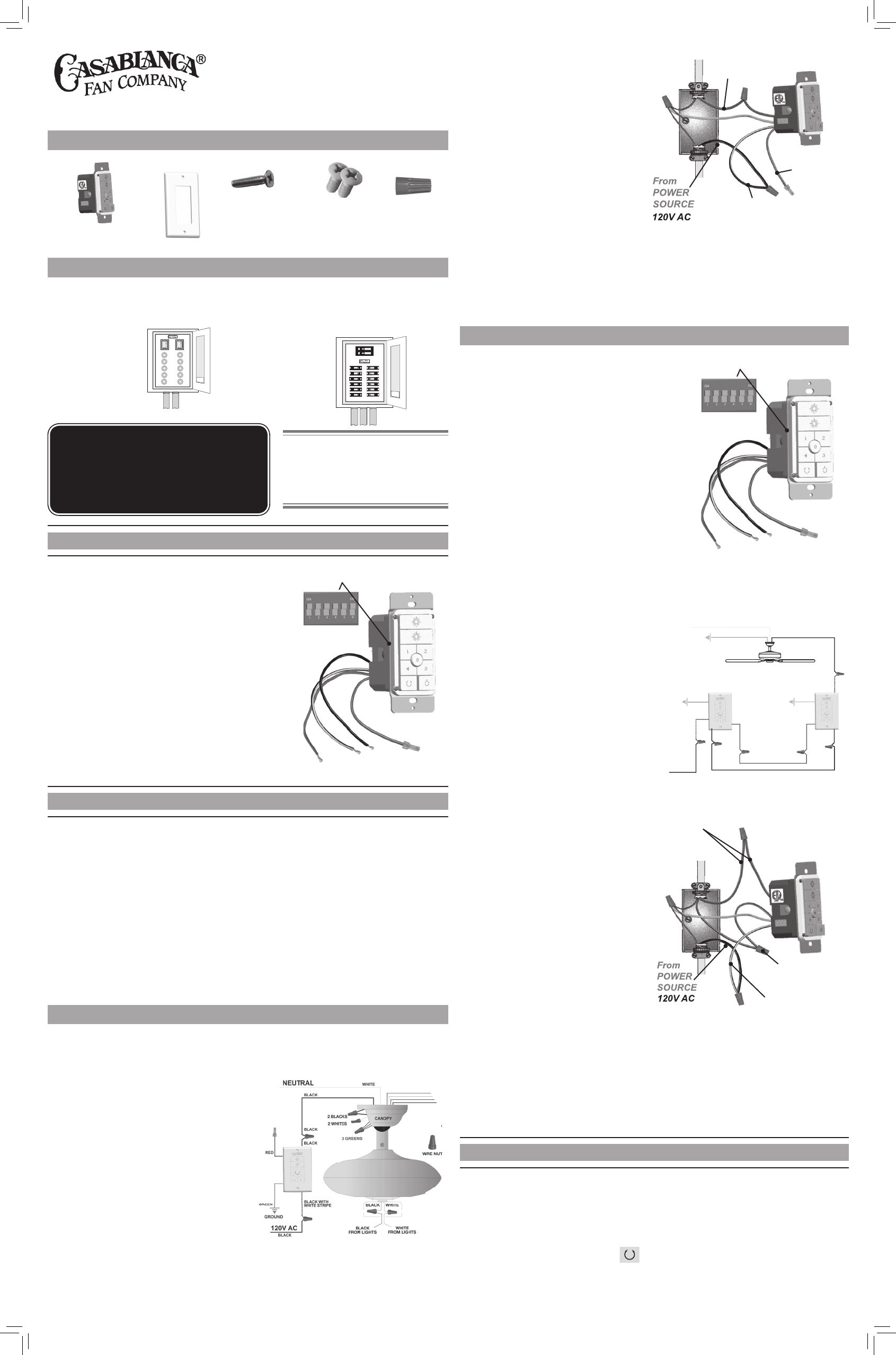
Setting the Frequency
DIP SWITCHES
(FIGURE #2)
To use this switch with an existing W-74 wall switch,
you must rst set the jumpers on the new switch to
match that of the existing one.
1. Turn off power to the existing wall switch.
2. Using a screw driver, remove the (2) wall plate
screws, then remove the (2) switch mounting
screws.
3. Gently remove the existing wall switch from the
wall and locate the dip switches located on the
side of the switch.
4. Change the dip switches on the new wall switch
to match the exisiting. (FIGURE 2)
5. Reinstall the existing wall switch.
inStalling the Wall control
The wall control installs in the same manner as an ordinary light switch, using an existing
wall box and wiring. This controller is designed to signal the fan microcomputer as well
as perform normal switching operations. For this reason the following precautions must
be observed:
1. Use only the Casablanca W-74 wall control.
2. Do not use any additional control with your Direct-Touch™ fan (for example, dimmer,
or fan speed control).
3. Do not use more than one fan per wall control.
4. No other light xtures or electrical appliances may be connected on the circuit con-
trolled by the W-74 wall control.
SINGLE W-74 INSTALLATION
CAUTION!
Ensure power is turned OFF at the breaker or fuse panel before starting
installation.
If you have multiple Direct-Touch™ fans,
refer to the section "Channel Changing".
1. Remove the screws and switch plate
from the existing switch box.
2. Remove the screws holding the switch
in the switch box.
3. Pull the existing switch from the switch
box to expose the wire connections.
4. Remove the two wires from the switch.
5. Connect the BLACK wire from the
POWER SOURCE that you just removed
from the switch to the BLACK/WHITE
STRIP wire on the W-74 wall control. Secure this connection with a wire nut.
6. Connect the second BLACK wire that
you just removed from the switch to
the second BLACK wire on the located
on the back of the W-74 wall control.
Secure this connection with a wire nut.
7. Connect the green ground wire coming
from the back of the W-74 control to the
ground wire in the switch box. Secure
the splice with a wire nut.
NOTE: The RED wire is not used in
this application. DO NOT remove the
crimped cap from the wire.
8. Check your work by using the wiring
diagrams as shown in Figure #3.
9. Install the W-74 in the wall box with the two long screws provided.
10. Install the wall plate with the two color-matched screws.
DUAL W-74 INSTALLATION
To control the fan and lights from two locations (a three-
way circuit), use two W-74 wall controls as shown in
the wiring diagram in Figure #5. Before installing
the two switches into the wall, place both switches
side by side, then locate the 4 dip switches on the
side of the two switches. Then make sure that the
dip switches are set to the same address on both
switches as shown in Figure #4. When setting these
dip switches you are setting the channel number
that is required to control both your fan and lights
from both sides of the room. If you are installing
other Direct-Touch™ fans within your home you
may need to reset the dip switches on these other
fans to a different channel before installing your
W-74 wall control into the wall. Please review the
section on channel changing on this instruction
sheet.
channel changing
Each fan must operate on it’s own frequency to prevent interference. Fan frequencies
are set by the dip switch settings on the W-74 wall control (other than to match an
existing W-74 controlling the same fan). To synchronize the fan to the new frequncy:
1. Turn the power OFF to the fan and W-74 you want to synchronize.
2. Turn the power back on to the fan and W-74 wall control.
3. Within 20 seconds of restoring power to the ceiling fan and the W-74 Wall Control
press and hold both the “1” and
1 2
0
4 3
reverse buttons. For 3 seconds, you will hear
one tone from the Piezo Buzzer indicating the command has been accepted. The
Fan and Lights will be off.
CAUTION!
Ensure power is turned OFF at the breaker or fuse panel before starting
installation.
W-74 Wall control HardWare
Wall Plate
Screws (2)
Switch
Mounting
Screws (2)
(4) Wire Cap
W-74
Wall Control Cover Plate
WARNING!
To avoid possible electrical shock, make
certain that electricity is turned off at
the circuit breaker or fuse box before
attempting any installation or repair
procedure
CAUTION! NOT turning the power
OFF at the circuit breaker or fuse box
may cause damage to the electronics
within the wall control and or the PC
board on the fan.
W-74 Wall control PreParation
Circuit Breaker
(Trip breaker for the
circuit you will be
working on)
Fuse Box
(Remove fuse for the
circuit you will be
working on)
BLACK AND WHITE
STRIPED WIRE
2 BLACK
WIRES
RED WIRE
NOT USED
(FiGUre #3)
(FIGURE #4)
DIP SWITCHES
BLACK
BLACK
RED
GREEN
120V AC
BLACK
BLACK WITH
WHITE STRIPE
W-74
RED RED
RED
BLACK WITH
WHITE STRIPE
GREEN
W-74
BLACK
BLACK
BLACK
BLACK
BLACK
NEUTRAL
WHITE
GREEN
(FIGURE #5)
W-74
Wall Control
BLACK AND WHITE
STRIPED WIRE
2 RED WIRES
2 BLACK
WIRES
(FIGURE #6)
W-74
Red
White
Blue
Black/White
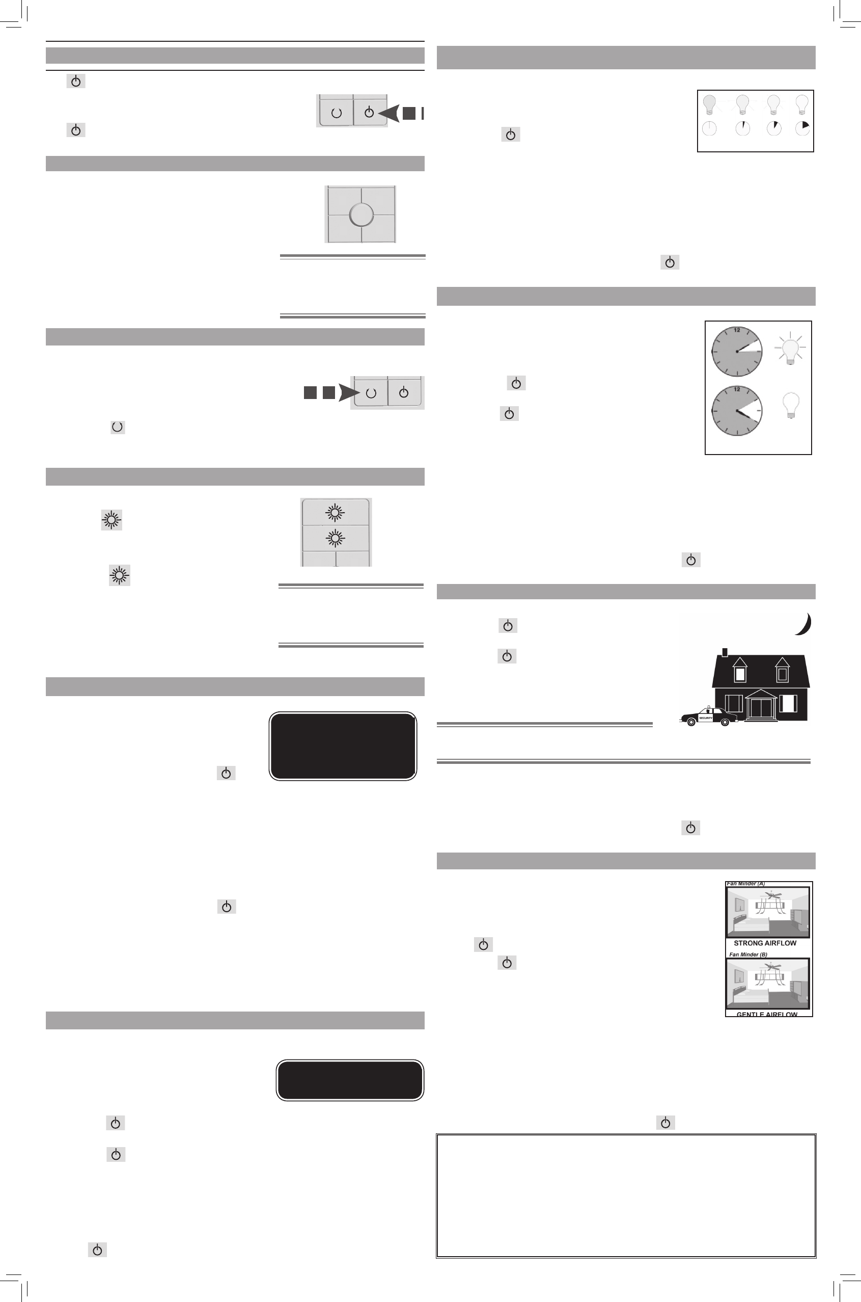
operation
OPERATION SPEED CONTROL
OPERATION REvERSING AIRFLOW
OPERATION LIGHTS
AUTOmATIC DEmONSTRATION PROGRAm
OPERATION HOmE-SAFE® PROGRAm
OPERATION FAN-mINDER™ PROGRAm
The
1 2
0
4 3
power button is normally left in the on
position. Always turn the power off during cleaning or
servicing the fan and during thunderstorms. It is also
used to exit or enter additional programs.
The
1 2
0
4 3
power button must be left on to retain a
previously set fan speed or light level.
1 2
0
4 3
There are ve individual speed settings
for the fan. Each speed is indicated by the
number on the controller and an audible tone
for each speed.
To select the desired fan speed:
Press the number on the controller
corresponding to the speed desired. 4 is high,
3 medium, 2 low, 1 ultra-low, and 0 is off.
1 2
0
4 3
Note: It is normal for the fan to start
in the "High" position from "O"
before changing to the selected
speed.
The direction of airow can be changed from
downward to upward or from upward to downward.
To reverse the airow:
1. Make sure the fan is on and blades are turning.
2. Press the
1 2
0
4 3
reverse button. You will hear a
series of clicks from the fan as it speeds up
before coming to a stop and changing direction.
1 2
0
4 3
To turn the lights off and on, press and
release the
1 2
0
4 3
button for either the up or
down lights for less than one second.
To dim either the up or down light, Press
and hold the
1 2
0
4 3
button for either the up or
down light for more than 1 second. The light
will come on at the last brightness setting
and increase in brightness until full power is
reached, then start dimming until the lowest
setting is reached. This cycle will repeat until
you release the light button.
1 2
0
4 3
Up Light
Down Light
Note: e dimming feature will only
work as long as the dimming feature
remains active. See "Operation CFL
mode".
Your fan has the ability to disable the
dimming feature to allow the use of CFL
bulbs.
To activate CFL mode:
1. Turn the fan off by pressing the
1 2
0
4 3
power button.
2. Allow the fan to remain off for at least 5 seconds.
3. Press the power button again to restore power to the fan.
4. Immediately press and hold the "1" and "3" buttons for at least 5 seconds.
The fans lights will go to 100% brightness and the dimming function will
be disabled.
To cancel CFL mode:
5. Turn the fan off by pressing the
1 2
0
4 3
power button.
6. Allow the fan to remain off for at least 5 seconds.
7. Press the power button again to restore power to the fan.
8. Immediately press and hold the "2" and "4" buttons for at least 5 seconds.
The fans lights will dim to 50% brightness and the dimming function will
be enabled. Press and hold the light buttons until the desired dimmer
setting is reached.
Caution: CFL bulbs will not
function properly when
dimmed, which may result
in ickering or reduced bulb
life.
oPeration cFl Mode
Programmed into every Direct-Touch fan is
an Automatic Demonstration Program. It can
be used to fully demonstrate and test the
operation of the fan.
To enter the demonstration program:
1. Turn the
1 2
0
4 3
power button off for at least
5 seconds. This will clear the fan memory ready for programming.
2. Turn the
1 2
0
4 3
power button on.
3. Immediately hold the "0" button for at least 5 seconds.
A multi-tone signal will verify the start of the test program. The fan and lights
will go through a series of changing fan speeds, reversing the fan operation
mode, turning off/on, and dimming the lights.
The complete cycle lasts slightly over one minute. It will continue to repeat
until the
1 2
0
4 3
is turned off for more than ve seconds, cancelling the program.
Note: With CFL mode active,
the lights will not dim.
oPeration SaFe-exit®
The Safe-Exit Program gives you about thirty
seconds of light when you turn the lights off,
enabling you to exit your home before the lights go
out. To enter the Safe-Exit Program:
1. Press the
1 2
0
4 3
power button off for at least ve
seconds.
2. Turn the Power on. Immediately press and
hold the "4" button for 5 seconds. When a
light button is pressed, an audio tone and series of lights blinking will
indicate the program is active. When CFL mode is disabled, the Lights will
stay on at 50% brightness for 20 seconds then decrease in intensity for 30
seconds then turn off.
3. With CFL mode active, the lights will turn off after 30 seconds.
4. To cancel the Safe-Exit Program, press the
1 2
0
4 3
power button and leave off
for ve seconds.
Safe-Exit
The Light-Minder Program automatically turns OFF
the fan mounted lights after two hours. To enter the
Light-Minder Program:
1. To operate the lights for Light Minder Program
– Turn the
1 2
0
4 3
power button off for at least 5
seconds.
2. Turn the
1 2
0
4 3
on. Immediately press and
hold the "1" button for 5 seconds. A series of
tones will be heard through the piezo-buzzer
indicating the command has been accepted.
Once the lights turn on, they will automatically
turn off after 2 hours.
3. Light operation still remains normal, if you leave the room and turn OFF
the lights, the lights will blink to indicate the Light Minder command has
been accepted. The lights will stay on for 2 hours and then begin to dim.
After thirty seconds have elapsed, the lights will turn completely off. In
CFL Mode, the lights will not dim, but shut off after 2 hours.
4. To cancel the Light Minder Program, press the
1 2
0
4 3
power button and
leave off for ve seconds.
liGHt-Minder® ProGraM
Light-Minder
1. To operate the Home-Safe Program –
Turn the
1 2
0
4 3
power button off for at
least 5 seconds.
2. Turn the
1 2
0
4 3
on. Immediately press and
hold the "3" button for 5 seconds. A
series of tones will be heard through the
piezo-buzzer indicating the command
has been accepted.
Note: is program overrides all manual control of
lights and fan.
3. The lights will automatically cycled on and off in a controlled sequence as
follows: ON 1 hour, OFF ½ hour, ON 2 hours, OFF 1 hour, ON ½ hour then
OFF 2 hours. This seven hour pattern will repeat continuously so that a
different pattern of lighting is seen each day of the week.
4. 4) To cancel the Home-Safe Program, press the
1 2
0
4 3
Button OFF for ve
seconds.
The Fan-Minder feature will add to your comfort when used
in the bedroom. The program reduces the speed of the fan
each two-hour interval to compensate for cooling night air.
1. To operate the lights for Light Minder Program – Turn
the
1 2
0
4 3
power button off for at least 5 seconds.
2. Turn the
1 2
0
4 3
on. Immediately press and hold the "2"
button for 5 seconds. A series of tones will be heard
through the piezo-buzzer indicating the command
has been accepted. Once the lights turn on, they will
automatically turn off after 2 hours.
3. The fan will respond with three descending tones. A
timer is now initiated and the fan will reduce one speed for each two-hour
interval. The fan will not, however, descend below the rst or the lowest
speed.
4. You may increase the fan speed by pressing and holding any of the fan speed
buttons until the desired speed is reached, then release it. The fan will again
reduce one speed for each 2 hour interval.
5. To cancel the Fan-Minder Program, turn the
1 2
0
4 3
OFF for 5 seconds.
*This device complies with part 15 of the FCC Rules. Operation is subject to the following
two conditions: (1) This device may not cause harmful interference, and (2) this device
must accept any interference received, including interference that may cause undesired
operation.
*This device complies with RSS-GEN IC: Operation is subject to the following two
conditions: (1) this device may not cause interference, and (2) this device must accept any
interference, including interference that may cause undesired operation of the device.
*Any alteration of this product, either intentional or unintentional, not expressly approved
by the manufacturer could result in operation failure of the device, inability to gain
assistance from our technical team, or manufacturer refusing warranty support.