Casi Rusco 1000-1010 1000/1010 Access Control Reader User Manual 00 cover
Casi Rusco 1000/1010 Access Control Reader 00 cover
UserManual.wiki
>
Casi Rusco
>
1000 1010 User Manual
Installation guide
Navigation menu
Upload a User Manual
Namespaces
Wiki Guide
HTML
PDF
Info
Views
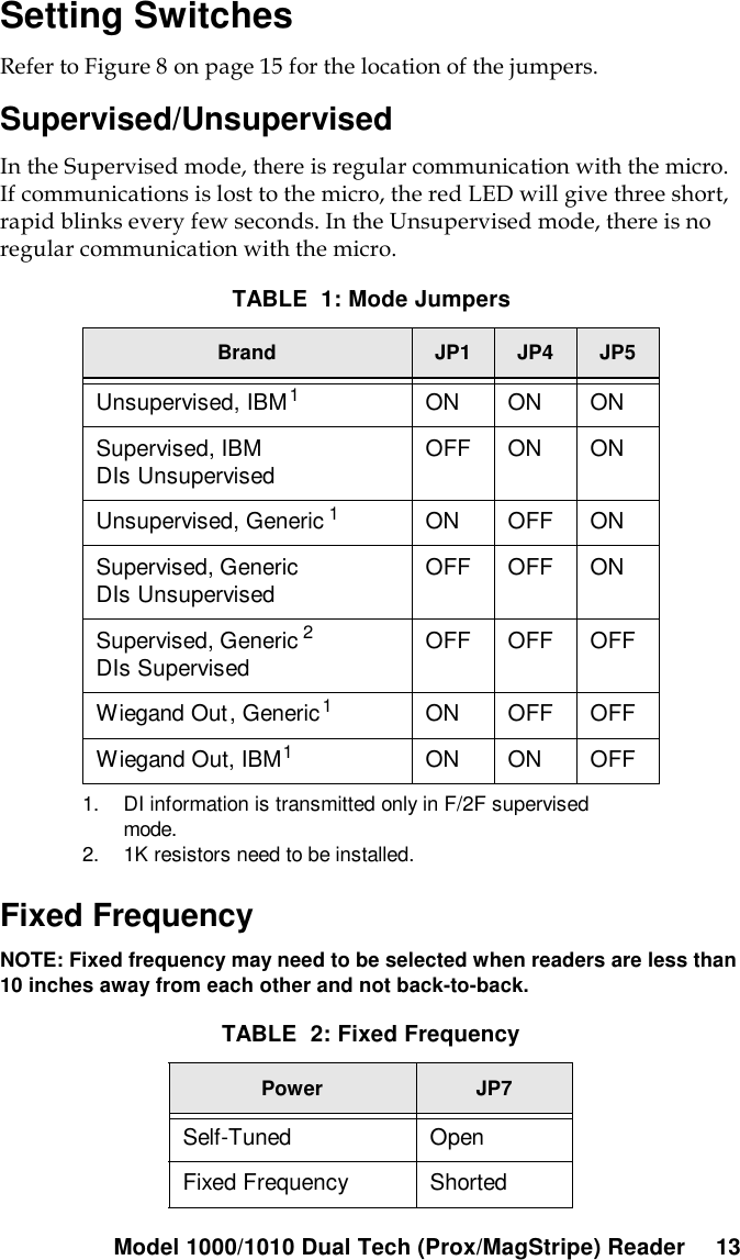
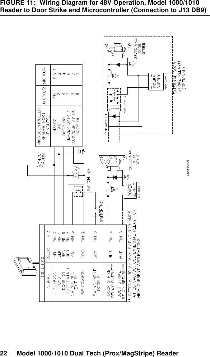
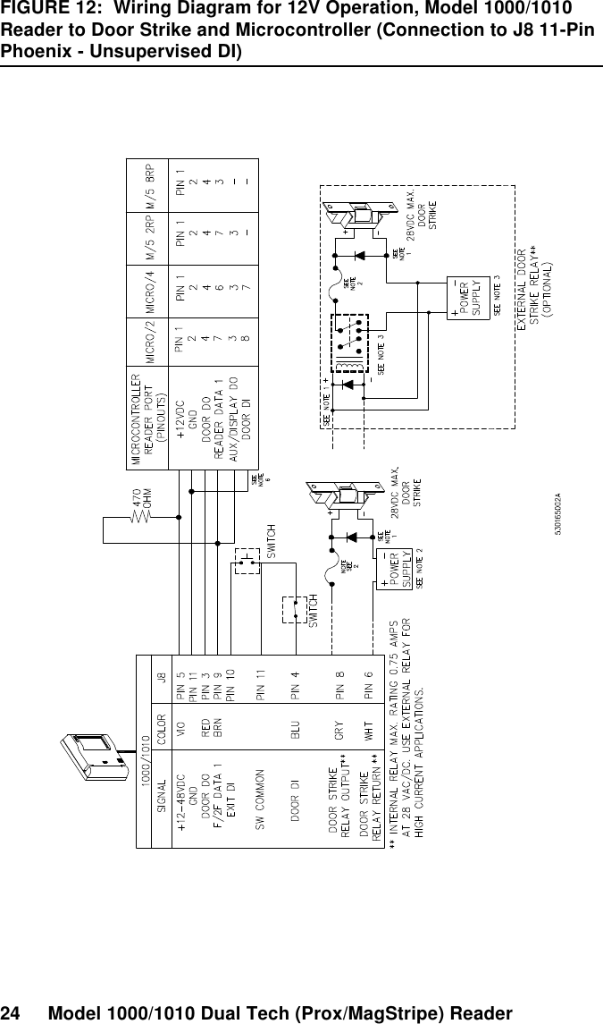
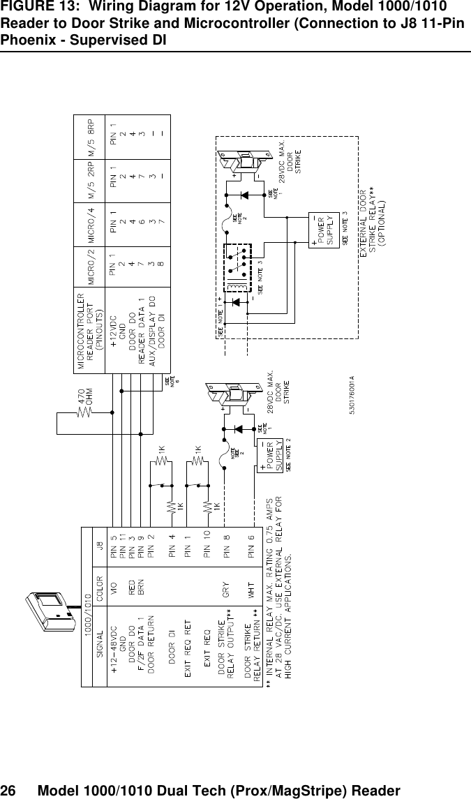
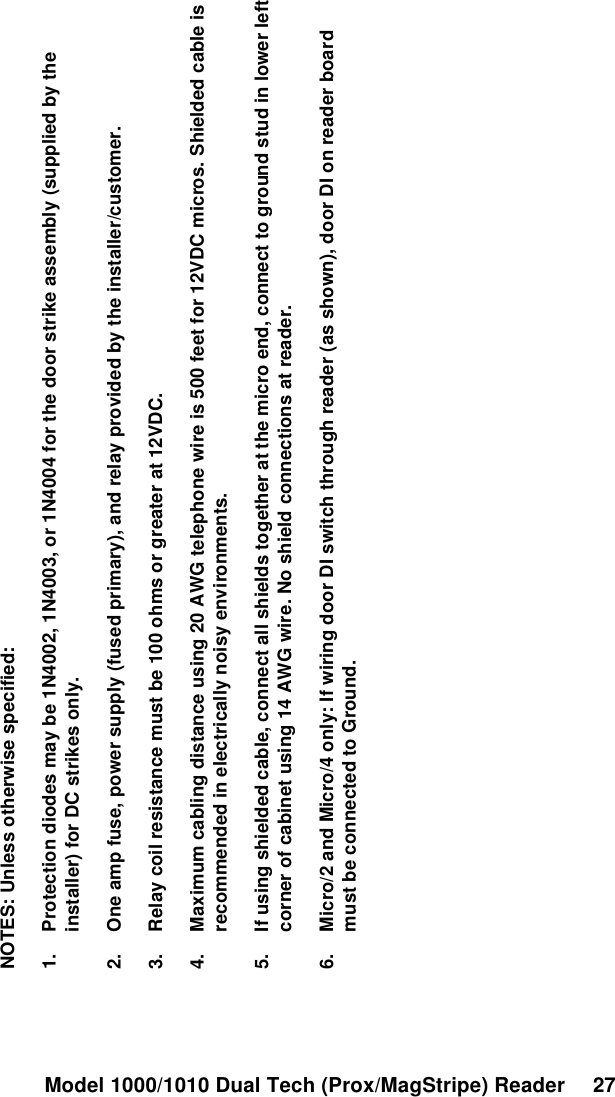
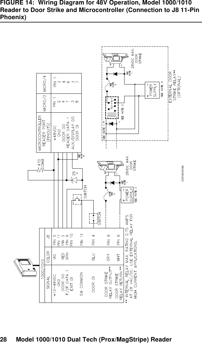
User Manual
Discussion / Help
Navigation