Casi Rusco 950-960 950/960 Proximity Readers User Manual Installation guide
Casi Rusco 950/960 Proximity Readers Installation guide
Installation guide

Part Number: 460158001H
March 2001
Model 950/960
Proximity Reader
Installation Guide
CASI
RUSCO
791 Park of Commerce Boulevard
Boca Raton, Florida 33487
(561) 998-6100
CASI-RUSCO...Security Solutions for the 21st Century
This publication may contain examples of data reports used in daily
business operations. Examples include fictitious names of individuals
and companies for illustration only; any similarity to names and
addresses of actual business enterprises and persons is entirely
coincidental.
This document is distributed on an as is basis, without warranty either
expressed or implied. Successful implementation depends solely upon
the customer’s ability to integrate each product into the total inventory
of “in-house” products. While each offering has been reviewed for its
compatibility and maintainability, no assurance of successful
installation can be given.
The customer accepts full maintenance responsibility. (A full scope of
software and hardware maintenance contracts are available to the
customer.)
Copyright 1993 - 1995, 1999 - 2001 CASI-RUSCO
All Rights Reserved
Printed in the USA
Proximity Perfect, ProxLite, ISO ProxLite, and Entrée are trademarks of
CASI-RUSCO.
Model 950/960 Proximit
y
Reader i
Contents
Introduction................................................................................................ 1
Product Features ........................................................................................ 1
Switch Settings ........................................................................................... 3
Selecting Reader Power Level ....................................................3
Selecting Operating Mode...........................................................7
Selecting Internal Beeper Sound Level......................................7
Mounting the Interface Unit..................................................................... 8
Mounting the 950 Read Head .................................................................. 9
Mounting the 960 Read Head ................................................................ 10
Connecting the Reader............................................................................ 12
CE/FCC Compliancy.................................................................12
Connecting the Interface Unit to the Read Head(s)...............14
Pinouts....................................................................................................... 15
Testing the Reader ................................................................................... 24
Troubleshooting Guide........................................................................... 25
All Installations...........................................................................25
Unsupervised Modes Only .......................................................27
Supervised Modes Only ............................................................27
Technical Specifications .......................................................................... 30
Functional Specifications ........................................................................ 32
ii Model 950/960 Proximity Reader
Figures
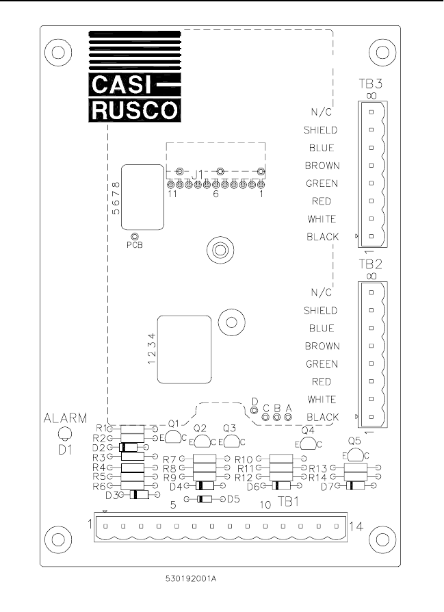
Figure 1: Interface Unit - Printed Circuit Board ............................ 4
Figure 2: Mounting the Interface Unit............................................ 8
Figure 3: Model 950 Reader - Mullion Mount................................ 9
Figure 4: Model 960 Reader - Glass Mount ................................ 11
Figure 5: Typical Installation Using Shielded Cable/Drain Wire.. 13
Figure 6: Interface Unit to Read Head Connection ..................... 14
Figure 7: Read Head Cable Pinouts............................................ 17
Figure 8: Wiring Diagram, Model 950/960 - Supervised
F/2F Mode.................................................................... 18
Figure 9: Wiring Diagram, Model 950/960 - Unsupervised
F/2F Mode.................................................................... 20
Figure 10: Wiring Diagram, Model 950/960 - Unsupervised
Wiegand Mode ............................................................ 22
Figure 11: Badge to Reader Presentation..................................... 32
Model 950/960 Proximit
y
Reader 1
Introduction
This manual is an installation guide for the CASI-RUSCO Models 950 and
960 Proximity Perfect™Readers. The Model 950 Reader is intended to be
mounted on the surface of a window mullion or door frame, and it is
specially tuned for installation on metal. The Model 960 Reader is
intended to be mounted directly on glass and has double-sided indicators
and a bi-directional read range.
Both readers consist of a metal boxed interface unit to be mounted in a
secured area and one or two compact read heads that communicate over
total cable lengths of up to 400 to 500 feet. The interface unit contains the
circuitry that drives any combination of up to two Model 950 or 960 read
heads. This performance is based on read heads manufactured after
September 1, 2000.
NOTE: For read heads manufactured prior to December, 2000, and mixed
heads, refer to the section entitled “Pinouts” beginning on page 15. The
cable length for read heads manufactured prior to December, 2000, remains
at 15 feet.
Product Features
The CASI-RUSCO Models 950 and 960 Proximity Perfect Readers offer:
• State-of-the-art architecture.
• The ability to read all ProxLite, ISO ProxLite, and Entrée badges.
• Miniature, unobtrusive read head design.
• Badge read range up to 4.3 inches (110 mm) for a Model 950 and 5.5
inches (140 mm) for a Model 960.
• A maximum of two 950 and 960 read heads may be connected to a
single interface unit, both acting as the same reader.
• If two read heads are used, each can be mounted up to 200 feet from
the interface, for a total of 400 feet of cable between the two heads.
• The Model 960 read head mounted on the secured side of a window
canreadbadgesontheunsecuredside.
• DIP switches allow all Models 950 and 960 Readers to operate in one
of four distinct operating modes: Wiegand, F/2F, Supervised F/2F,
and Silent Supervised F/2F. Silent Supervised mode is ideal for
installations where no audible or visual indication of communication
loss with the microcontroller is desired at the reader.
• In the unsupervised modes (Wiegand and F/2F), the reader
communicates with the microcontroller over a uni-directional
Wiegand or F/2F data link that carries Proximity Perfect badge data
only.
2 Model 950/960 Proximity Reader
• In the Supervised modes (F/2F and Silent F/2F), the reader
communicates with the microcontroller over a bi-directional F/2F
data link that carries the following:
• Proximity Perfect badge data
• Supervision messages
• Exit request and door contact status
• Microcontroller acknowledgments and commands
• Intelligent bi-directional communication between the interface unit
and microcontroller, which can be accomplished up to 5,500 feet
(1676 m) over 22 AWG telephone cable.
• The interface unit has an integral beeper along with a provision for
driving an installer-supplied remote +12VDC beeper.
• Weatherproof read head (Model 950 only).
• Built-in tamper switch on the interface unit with provisions for
connecting additional installer-supplied tamper switches.
• The interface unit has a red LED, the read head has one yellow, and
one green LED.
• Standard 12V operation.
• Rugged molded ABS construction with integral backplate.
Model 950/960 Proximit
y
Reader 3
Switch Settings
Two banks of four DIP switches located inside the interface unit are used
to select the reader power level, operating mode, and internal beeper
sound level.
CAUTION: Power should be removed from the reader while switch settings
are changed.
Selecting Reader Power Level
The reader’s power requirement is selected using four DIP switches. The
optimum power level will vary with each installation. Higher power
levels give improved read range for Proximity Perfect badges; while
lower power levels allow greater cabling distance between the reader and
the microcontroller. A detailed explanation is provided below. The
reader’s power requirements are unaffected by the connection ofa second
read head to the interface unit. The figure on the next page shows the
location of the DIP switches. The tables that follow give the switch
settings, read ranges, and cabling distances.
Explanation of Read Range/Cable Distance/Power Level:
Maximum badge read range is determined by the distance at which the
field transmitted by the reader is just strong enough to wake up the
badge. Therefore, the higher the reader’s transmission power, the greater
the badge read range will be. The trade-off for increased read range is a
decrease in the maximum cabling distance between the reader and the
microcontroller. The trade-off between read range and cabling distance is
common to all proximity badge readers. The power selection switches on
the Models 950 and 960 Readers allow the optimum power setting to be
selected to suit individual installations.
For example: On the high power setting, giving the greatest badge read
range, the reader typically requires 200mA of supply current from the
microcontroller. If there is 1,000 feet of 22 AWG cable between the reader
and the microcontroller, the total reader power and power return path is
2,000 feet. Since 22 AWG cable has a typical resistance of 16 ohms per
1,000 feet, the total resistance in the reader’s power and power return
wire is 32 ohms. By Ohms Law (V=IR), it follows that the total voltage
dropped in the reader power and power return wires will be 6.4V
(6.4V = 200mA x 32 ohms). Therefore, the reader supply voltage willdrop
from 12V at the microcontroller to 5.6V (12V - 6.4V) at the reader. Such a
supply voltage is too low for the reader to function reliably.
4 Model 950/960 Proximity Reader
If the low power setting is selected, the badge read range is reduced.
However, the reader now typically requires only 75mA of supply current;
therefore, the voltage drop in the power and power return wires is much
less. In this case, the reader supply voltage will only be reduced to 9.6V,
high enough for reliable operation.
Figure 1: Interface Unit - Printed Circuit Board

Model 950/960 Proximit
y
Reader 5
CAUTION: Power should be removed from the reader while switch settings
are changed.
The table below gives the switch settings for the three power levels.
The table below gives the read ranges for each of the readers based on the
power level settings and whether one or two read heads are connected to
the interface unit. If a Model 950 and 960 read head are connected to the
same interface unit, refer to the read ranges in the Dual 950 and Dual 960
columns. All read ranges are typical maximums, measured with up to 20
feet cable length between interface unit and read head.
in = inches
mm = millimeters
NOTE: The above distances are typically valid up to 100 feet between
interface and read head. Beyond 100 feet, the range decreases to "almost
contact" at 500 feet.
TABLE 1: Power Level Switch Settings
Power
Level Switch 1 Switch 2 Switch 3 Switch 4
LOW OFF ON ON OFF
MEDIUM ON OFF OFF ON
HIGH ON ON ON ON
TABLE 2: Read Range by Model Number
Power
Level Single 950 Dual 950 Single 960 Dual 960
LOW 2.8 in
70 mm 2.4 in
60 mm 3.1 in
80 mm 2.8 in
70 mm
MEDIUM 3.5 in
90 mm 3.1 in
80 mm 4.7 in
120 mm 4.3 in
110 mm
HIGH 4.3 in
110 mm 3.5 in
90 mm 5.5 in
140 mm 4.7 in
120 mm

6 Model 950/960 Proximity Reader
The table below gives the maximum cabling distances between the reader
and the microcontroller for the three power levels.
ft = feet
m=meters
NOTES:
1. Reader supply voltage measured at microcontroller: 13.6V is nominal
when line powered, 12V is nominal when battery powered.
2. Not recommended for 12V, battery-backed installations.
3. All cabling distances are typical maximums.
4. Readers powered by a local 12VDC power supply will have a maximum
cable distance of 5,500 feet (1676 m) of 22 AWG telephone wire for all
power level settings.
5. In Wiegand mode, the maximum cable distance is 1,000 feet (305 m) of
shielded cable.
TABLE 3: Cabling Distances
Power
Level
13.6 Volts (see Note 1) 12 Volts (see Note 1)
18 AWG 22 AWG 18 AWG 22 AWG
LOW 5500 ft
1676 m 2000 ft
610 m 3500 ft
1067 m 1500 ft
457 m
MEDIUM 2200 ft
671 m 900 ft
274 m 1100 ft
335 m 450 ft
137 m
HIGH 600 ft
183 m 250 ft
76 m See Note 2 See Note 2

Model 950/960 Proximit
y
Reader 7
Selecting Operating Mode
The table below shows the DIP switch settings for the four operating
modes.
Selecting Internal Beeper Sound Level
The table below shows the DIP switch settings for the three beeper
sound levels for the internal beeper. An optional installer-supplied
remote beeper connected to TB1 is unaffected by these switch settings.
TABLE 4: Operating Mode DIP Switch Settings
Operating Mode Switch 5 Switch 6
Wiegand1
1. In the Wiegand operating mode, 2801, 2804, and 3201 Proximity
Perfect badge data is sent out using 2801, 2804, and 3201 Wiegand
format, respectively. Badge data for Proximity Perfect badges
encoded using the 40-bit format is sent out using Wiegand format. All
ProxLite badge data is sent out using 4401 Wiegand format.
OFF OFF
F/2F2
2. In operating modes other than Wiegand, 2801, 2804, and Proximity
Perfect badge data is sent out using a 10-digit F/2F format. Badge
data for Proximity Perfect badges encoded using the 40-bit format
and ProxLite badge data are sent out using a 12-digit F/2F format.
ON OFF
Supervised F/2F2OFF ON
Silent supervised F/2F2ON ON
TABLE 5: Beeper Sound Level DIP Switch Settings
Beeper Sound Level Switch 7 Switch 8
Normal ON ON
Low ON OFF
Off OFF ON

8 Model 950/960 Proximity Reader
Mounting the Interface Unit
The interface unit should be mounted in a sheltered, secured location,
such as above a ceiling. If one read head is used, it can be mounted 500
feet from the interface unit. If two read heads are used, each can be
mounted up to 200 feet from the interface, for a total of 400 feet between
the two heads. The cable that comes attached to the read head can be
shortened to less than 20 feet, or can be extended with Belden 9536,
6-conductor #24 AWG shielded, or equivalent type cable, to a maximum
of 500 feet. The read range varies from the typical numbers with distance.
At 500 feet cable distance to read head, the range reduces to “almost
contact.”
Figure 2: Mounting the Interface Unit

Model 950/960 Proximit
y
Reader 9
Mounting the 950 Read Head
The Model 950 read heads are designed to be mounted on the surface of a
door frame or window mullion using the two security screws provided.
CAUTION: Readers should not be mounted within 3 feet (1 meter) of a
computer terminal. Some terminals radiate electrical noise that may reduce
the maximum read range.
Once the reader is attached to the mullion, place the self-adhesive lexan
label on the front of the reader to cover the screw heads, and diffuse the
LEDs.
Figure 3: Model 950 Reader - Mullion Mount
10 Model 950/960 Proximity Reader
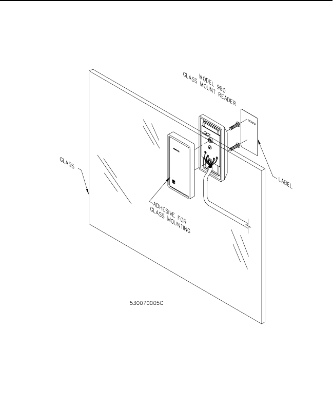
Mounting the 960 Read Head
The Model 960 double-sided read heads are designed to be mounted
directly onto a glass surface such as a window. Read heads can be
mounted on any of the following types of glass surfaces without causing
significant reduction in read range.
•Clear
•Tinted
•Reflective
• Glass tinting films
NOTE: Read range may be significantly reduced when the read heads are
mounted on certain types of highly reflective or reinforced glass.
CASI-RUSCO cannot guarantee that a specific glass, coating, or film will not
cause a significant reduction in read range. CASI-RUSCO will test any glass
type if a sample is supplied by the customer.
Thereadheadshouldbepositionedatleast6inches(150mm)fromlarge
metal objects, such as metal doors or window mullions.
CAUTION: Readers should not be mounted within 3 feet (1 meter) of a
computer terminal. Some terminals radiate electrical noise that may reduce
the effective maximum read range.
Follow the steps below.
1. Decide where to mount the read head, and determine the direction
that the interface cable should exit.
2. Remove the selected “break-out” slot with a pair of needle-nose
pliers.
3. Screw the two halves of the read head together while ensuring that
the interface cable exits through the open “break-out slot.”
4. Be sure the glass surface is perfectly clean, grease free, and dry to
ensure reliable read head adhesion. Remove the backing film,
accurately position the read head, and press it firmly against the
glass. Maximum adhesive strength is attained after 24 hours.
5. Route the interface cable to the interface unit carefully so that you do
not pull the read head off the glass.
6. Place the self-adhesive lexan label on the front of the reader to cover
the screw heads, and diffuse the LEDs.
Model 950/960 Proximit
y
Reader 11
Figure 4: Model 960 Reader - Glass Mount
12 Model 950/960 Proximity Reader
Connecting the Reader
CE/FCC Compliancy
NOTE: As of January 1, 1996, all new European Installations MUST be
CE compliant.
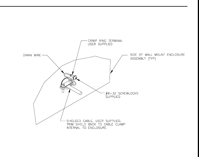
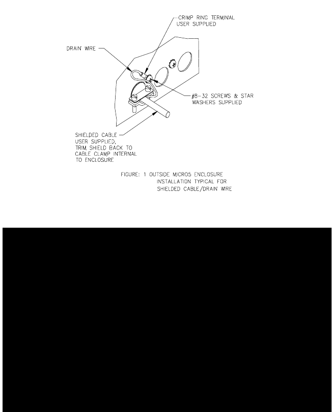
• The cable connecting the Model 950/960 Reader to the Micro/5
must have its shield grounded at the Micro/5 as indicated in
Figure 5.
• The cable connecting the 950/960 read head to the wall mount
assembly must have its shield grounded as indicated in Figure 5.
• If a local power supply is used, the wires entering the 950/960
enclosure must be shielded and the shield terminated as
indicated in Figure 5.
Figure 5: Typical Installation Using Shielded Cable/Drain Wire
Outside of Proximity Interface Unit
(Wall Mount Enclosure)
Model 950/960 Proximit
y
Reader 13
Outside of Micro/5 Enclosure
Inside of Micro/5 Enclosure
Outside Micro/5 Enclosure

14 Model 950/960 Proximity Reader
Connecting the Interface Unit to the Read Head(s)
The drawing below shows an overview of how to connect the interface
unit to the read head(s). See the wiring diagrams that follow for details on
connecting the read heads, interface unit, and microcontroller based on
themodeofthereader.
Figure 6: Interface Unit to Read Head Connection

Model 950/960 Proximit
y
Reader 15
Pinouts
The table below shows terminal block TB1 position numbers and
corresponding signals for connecting the interface unit to the
microcontroller. Position 1 of TB1 is to the left as you view it inside the
interface unit. See Figure 1: Interface Unit - Printed Circuit Board on
page 4.
TABLE 6: Terminal Block TB1 Positions/Signals
Terminal
Position # Signal
1+12VDC
2 Ground
3 Red LED Control
4 Green LED Control
5 Yellow LED Control
6 Reader Data 0
7 Reader Data 1
8 Beeper Control
9 Remote Beeper Drive
10 Door DI (Door Contact Switch)
11 Exit DI (Exit Request Button)
12 Tamper
13 Tamper Ground
14 Beeper Ground

16 Model 950/960 Proximity Reader
CAUTION: The read heads have improved performance over read heads
manufactured before December, 2000. Therefore, if the read head is to be
used as a second read head or as a replacement in a two-head application,
the following precautions for wiring changes must be observed.
To determine if read head was manufactured before December, 2000, one
of the following conditions will exist:
• Read head part number label reads, REV. A.
• If the read-head cable at the interface has a shrink wrap label with the
text, DO NOT EXTEND OR CUT.
• If there is an existing second read head, the connections are reversed
at the connector (Red on 4 and Green on 3).
• If both read heads fail to work when the new read head is installed.
IfONEreadheadisnewandonereadheadisold,thenconnectusingthe
appropriate New Wiring configuration, as shown in Figure 7, Read Head
Cable Pinouts.
If BOTH read heads are new, then connect using the appropriate New
Wiring configuration without the diode, as shown in Figure 7, Read Head
Cable Pinouts.
The diode is included in this package and has the orientation shown
below:
The diode is to be inserted between the RED lead from the read head and
Terminal 3 on the interface. If you cannot determine the version of the
existing read head, the diode can be installed between the RED lead and
Terminal 3, in either version without detriment.

Model 950/960 Proximit
y
Reader 17
Figure 7: Read Head Cable Pinouts

18 Model 950/960 Proximity Reader
Figure 8: Wiring Diagram, Model 950/960 - Supervised F/2F Mode
Model 950/960 Proximit
y
Reader 19
NOTES (Unless otherwise specified):
1. For Micro/2/4/5 only: a 470 ohm, 1/2W pull-up resistor is required between +12VDC and READER DATA 1. The pull-up
resistor should be installed at the microcontroller terminal block. Resistors are supplied with the reader.
2. Shielded cable is recommended in electrically noisy environments. Connect all shields together at the micro end,
then connect them to the ground stud in the lower left corner of Micro/2/4/5 cabinets using 14 AWG wire. Do not
connect the shields at the reader.
3. Refer to the appropriate system manual to determine whether this connection is required for door switch operation.
4. If using a local power supply, do not connect +12V line from the microcontroller to the reader. However, the negative
side of the power supply must be connected to the micro (TB1, position 2 on the reader port). Keep wiring from power
supply to reader, less than 50 feet.
5. Switching the external indicator drives to GND activates the indicator. High impedance de-activates the indicator.
These drives may also be connected to user-supplied, external indicator driving circuitry.
6. The installer-supplied blocking diode may be a 1N4002, 1N4148, or similar diode. It should be located in a secured
area.
7. The installer-supplied protection diodes for the door strike assembly may be 1N4002, 1N4003, or 1N4004.
8. The fuse, power supply, door strike, and relay are provided by the installer.
9. If you are not using the door contact switch, tie the DOOR DI (TB1 position 10) wire to GND (TB1 position 2).
10. An optional installer-supplied, normally closed, tamper switch should be connected in series with the standard
interface unit tamper switch.
11. Tie the BEEPER ENABLE (Orange) wire to GND (Black) wire to disable the beeper.

20 Model 950/960 Proximity Reader
Figure 9: Wiring Diagram, Model 950/960 - Unsupervised F/2F Mode
Model 950/960 Proximit
y
Reader 21
NOTES (Unless otherwise specified):
1. For Micro/2/4/5 only: a 470 ohm, 1/2W pull-up resistor is required between + 12VDC and READER DATA 1. The pull-up
resistor should be installed at the microcontroller terminal block. Resistors are supplied with the reader.
2. Shielded cable is recommended in electrically noisy environments. Connect all shields together at the micro end,
then connect them to the ground stud in the lower left corner of Micro/2/4/5 cabinets using 14 AWG wire. Do not
connect the shields at the reader.
3. Refer to the appropriate system manual for specific wiring details.
4. If using a local power supply, do not connect +12V line from the microcontroller to the reader. However, the negative
side of the power supply must be connected to the micro (TB1, position 2 on the reader port). Keep wiring from power
supply to reader, less than 50 feet.
5. Switching the external indicator drives to GND activates the indicator. High impedance de-activates the indicator.
These drives may also be connected to user-supplied, external indicator driving circuitry.
6. The installer-supplied blocking diode may be a 1N4002, 1N4148, or similar diode. It should be located in a secured
area.
7. The installer-supplied protection diodes for the door strike assembly may be 1N4002, 1N4003, or 1N4004.
8. The fuse, power supply, door strike, and relay are provided by the installer.
9. An optional installer-supplied, normally closed, tamper switch should be connected in series with the standard
interface unit tamper switch.

22 Model 950/960 Proximity Reader
Figure 10: Wiring Diagram, Model 950/960 - Unsupervised Wiegand
Mode
Model 950/960 Proximit
y
Reader 23
NOTES (Unless otherwise specified):
1. For Micro/2/4/5 only: two 470 ohm, 1/2W pull-up resistors are required; one between +12VDC and READER DATA 1,
the other between +12VDC and READER DATA 0 . The pull-up resistors should be installed at the microcontroller
terminal block. Resistors are supplied with the reader.
2. Shielded cable is required. Belden 8725 wire is recommended. Do not pair DATA 1 and DATA 0. Connect all shields
together at the micro end, then connect them to the ground stud in the lower left corner of Micro/2/4/5 cabinets using
14 AWG wire. Do not connect the shields at the reader.
3. Refer to the appropriate system manual for specific wiring details.
4. If using a local power supply, do not connect +12V line from the microcontroller to the reader. However, the negative
side of the power supply must be connected to the micro (TB1, position 2 on the reader port). Keep wiring from power
supply to reader, less than 50 feet.
5. Switching the external indicator drives to GND activates the indicator. High impedance de-activates the indicator.
These drives may also be connected to user-supplied, external indicator driving circuitry.
6. The installer-supplied blocking diode may be a 1N4002, 1N4148, or similar diode. It should be located in a secured
area.
7. The installer-supplied protection diodes for the door strike assembly may be 1N4002, 1N4003, or 1N4004.
8. The fuse, power supply, door strike, and relay are provided by the installer.
9. An optional installer-supplied normally closed tamper switch should be connected in series with the standard
interface unit tamper switch.
24 Model 950/960 Proximity Reader
Testing the Reader
Follow the steps below to verify that the reader is working correctly.
1. Check all cabling and electrical connections from the read head(s) to
the interface unit and the interface unit to the microcontroller. Refer
to the wiring diagrams.
2. Verify that the microcontroller is properly configured. Refer to the
appropriate CASI-RUSCO microcontroller manual.
3. Verify that the interface unit switches are properly set for the power
setting, cabling type, distance, and desired mode of operation. See
“Switch Settings” on page 3.
4. Apply power to the reader, andverify that theyellow LED at the read
head(s) is on. You may want to use a multimeter to test the voltage at
the interface unit TB1 using ground (position 2) as a reference. Power
(position 1), data lines (positions 6 & 7), and door DO (position 4)
should all read approximately 12V.
5. Check that the proper version of firmware is installed in the
microcontroller. Refer to the appropriate microcontroller manual.
6. Close the tamper switch by closing the interface unit door. When all
wires are connected to the reader, ensure that the supervision
function is operating properly (if a supervised mode is selected) by
verifying that the reader is not sounding a short, triple beep every
30 seconds and the red LED is not flashing slowly (every 2 seconds).
You must press the tamper switch in order to check the red LED since
it will turn on as soon as you open the interface unit door. If an alarm
is present, refer to the Troubleshooting Guide.
NOTE: In silent supervised mode, no indication of loss of supervision is
provided, except badges will not be read.
7. Select a known good Proximity Perfect, ProxLite, ISO ProxLite, or
Entrée test badge. Be sure the badge is properly entered in the host
system,andthemicrobadgedataformatmatchesthereader.
8. Check that the door is secure. Present the badge to the reader.
Observe that the interface unit beeps briefly, and the yellow LED on
the read head blinks off.
9. Observe that the green LED turns on indicating a valid access has
been granted by the host.
10. Open the door. This verifies that the door strike operates correctly.
Model 950/960 Proximit
y
Reader 25
Troubleshooting Guide
If the operation of a component is in doubt, substitute a known good
component and retry the system. Always verify wiring against wiring
diagrams before powering up the system.
This section of the manual is split into three sections. The first is
applicable to all installations, the second provides additional diagnosis
for unsupervised readers, and the final section provides additional
diagnosis for supervised readers.
NOTE: When you open the interface unit door to check the red LED, be sure
to press the tamper switch to temporarily bypass the tamper alarm.
Remember that opening the door causes a tamper condition which turns on
the red LED.
All Installations
All LEDs are on, and the beeper is on (if enabled):Usually,an
indication that the reader’s voltage is too low. This may be caused by
having the wrong reader voltage selected at the microcontroller or too
long a cable between the reader and the microcontroller.
1. Measure the reader supply voltage at the microcontroller. It should
read between 12 and 15VDC. If the voltage is correct, continue to
step 2 below. If the voltage is incorrect, refer to the appropriate
microcontroller manual and correct the voltage.
2. Set the reader to low power mode if the cable distance is too long (See
Table 1, “Power Level Switch Settings,” on page 5). This may correct
the problem.
3. If the problem is still present, while in low power mode, measure the
voltage between TB1 position 1 (power) and TB1 position 2 (ground)
on the interface unit. This voltage should be greater than 8VDC and
less than or equal to the reader supply voltage. If the voltage is too
low, correct the wiring. If the voltage is correct, replace the reader.
None of the LEDs are on: Check that the beeper is enabled
(See Table 5, “Beeper Sound Level DIP Switch Settings,” on page 7), then
present a known good Proximity Perfect, ProxLite, ISO ProxLite, or
Entrée testbadge tothe reader while listening for the beeper. If the beeper
sounds, the reader is faulty and shouldbe replaced. If the beeper does not
sound, check the power connections to the reader and check the reader
supply voltage at TB1 position 1 on the interface unit.
The green LED is always on: The green LED indicates that the door
strike is open. It is controlled by the input on TB1 position 4.
26 Model 950/960 Proximity Reader
1. Disconnect the wire on TB1 position 4 on the interface unit. If the
green LED stays on, the reader is faulty and should be replaced. If the
green LED goes off, then the problem is most likely not in the reader.
2. ReconnectthewireonTB1position4andmeasurethevoltageatTB1
position 4. Low voltage turns on the green LED. If the voltage is low,
check to see if the host system is turning on the door strike.
The beeper doesn’t sound, and the yellow LED doesn’t blink
when a badge ispresented to the reader OR the badge read range
is very poor: When the beeper sounds and the yellow LED blinks off, it
indicates that a badge has been read and its data sent to the
microcontroller.
NOTE: The interface unit beeper will not sound if it has been disabled (See
Table 5, “Beeper Sound Level DIP Switch Settings,” on page 7).
1. Verify that the read heads are correctly wired as shown in “Read
Head Cable Pinouts” on page 17.
2. Check that the Model 960 Reader is not mounted on or within 6
inches of a large metal object, such as a metal door or window
mullion.
3. Check the reader supply voltage onTB1 position 1 at the interface
unit.
4. Check that the reader is not mounted within 3 feet (1 meter) of a
computer terminal or within 10 inches (250 mm) of another Proximity
Perfect reader. The only exception to the 10-inch limit is for 950 read
heads mounted back-to-back on a mullion.
5. Present a Proximity Perfect test badge (known to be working) to the
read head. If the beeper and yellow LED still fail to indicate a valid
badge read and send, replace the reader with a reader that you know
is working correctly. If this corrects the problem, the original reader
is faulty and should be replaced. If this does not correct the problem,
the badge is probably defective.
The door does not open, and the green LED does not turn on
when a badge is presented:
1. Verify that the badge and reader are properly entered into the
system.
2. Verify that the door strike and the green LED are wired correctly.
SincethegreenLEDandthedoorstrikeareseparateindicators,this
problem is not an indication of a defective reader.
Model 950/960 Proximit
y
Reader 27
The green LED does not turn on, but the door strike unlocks the
door when a valid badge is presented:
1. Verify that the door DO is wired correctly. Refer to the appropriate
wiring diagram.
2. Disconnect the wire from TB1 position 4 on the interface unit and
connect TB1 position 4 to ground, TB1 position 2. If the green LED is
now on, the reader is good, and the connection to the reader is
defective. If the green LED does not turn on, replace the reader.
The green LED turns on, but the door does not open: Verify correct
door strike wiring and operation. The reader is functioning properly.
Unsupervised Modes Only
Beeper sounds a short, triple beep every 30 seconds, and the red
LED is on: Indicates a tamper violation. Verify that the interface unit
door is closed or the interface unit tamper switch is temporarily pressed.
If it is either, verify that any additional installer-supplied tamper
switch(es) are wired correctly. Refer to the appropriate wiring diagram.
Supervised Modes Only
Reader sounds a short, triple beep every 30 seconds, and the red
LED flashes every two seconds: The reader has lost communication
with the microcontroller.
NOTE: When you open the interface unit door to check the red LED, be sure
to press the tamper switch to temporarily bypass the tamper alarm.
Remember that opening the door causes a tamper condition which causes
the red LED to flash.
1. Check the reader-to-microcontroller wiring. Refer to the appropriate
installation drawing. Verify that the AUX DO is jumpered to the
READER DATA 1 at the microcontroller.
2. Verify that the correct pull-up resistor is installed on the
microcontroller. See Figure 8: Wiring Diagram, Model 950/960 -
Supervised F/2F Mode on page 18.
3. Verify that the microcontroller has the correct firmware for a
supervised reader. Refer to the manual that came with your
microcontroller for instructions.
28 Model 950/960 Proximity Reader
4. Try the reader on a different reader input of the microcontroller. If
this corrects the problem, then the microcontroller is probably
causing the problem.
5. Replace the reader with one you know is working correctly. If this
corrects the problem, then the reader is probably faulty and should
be replaced.
6. If none of the above steps has identified the problem, there may be a
significant noise source present in the installation which is interfering
with the reader-to-microcontroller communications. If this is the case,
use shielded wire for reader-to-microcontroller connections.
The green LED flashes fast (every 400ms): Indicates that the
microcontroller has requested a PIN entry. Check the reader
configuration on your system to be sure a keypad reader was not
selected.
The beeper sounds, and the yellow LED blinks off more than
once when a valid badge is presented: The beeper sounds, and
the yellow LED blinks off every time badge data is sent to the
microcontroller. When a badge is presented to the read head, data is
transmitted from the badge to the reader. The reader interprets and
checks the data received to make sure it has not been corrupted.
The reader then sends the data to the microcontroller and waits
approximately 1/3 of a second for the microcontroller to acknowledge
receipt. If no acknowledgment is received during this time, the reader
resends the data causing the beeper to sound again and the LED to blink
off. After the third unacknowledged attempt, the reader stops trying
and indicates a communications error. This feature is useful in
troubleshooting marginal installations where a high level of electrical
noise may cause the reader to make multiple attempts at
communications.
1. If multiple beeps occur regularly, refer to the installation drawings
to verify that the correct pull-up resistor has been added to the
microcontroller.
2. Replace the reader with one you know is working correctly. If this
solves the problem, the original reader is probably faulty and should
be replaced. If the problem persists, use shielded cable between the
microcontroller and the reader.
Model 950/960 Proximit
y
Reader 29
The reader sounds a short triple beep every 30 seconds, and the
red LED flashes quickly (every 400ms): Indicates a tamper violation.
Verify that the interface unit door is closed or the interface unit tamper
switch is temporarily pressed. If it is, verify that any additional installer-
supplied tamper switch(es) are wired correctly. Refer to the appropriate
wiring diagram.
The beeper and/or red LED are always on: The microcontroller may
command the reader to turn on the red LED and the beeper as long as the
reader DIP switches are not set to disable the beeper. If the door status
switch input (TB1 position 10) is not tied to ground, the reader informs
the system that the door is open. The system may then activate the alarm
at the reader.If thisis not the problem,then the system software probably
told the reader to activate its alarm. Refer to the appropriate system
manual for conditions that cause the software to activate the alarm. If it
appears that no such system command is active, replace the reader with
one you know works correctly. If this solves the problem, the original
reader is faulty and should be replaced.
30 Model 950/960 Proximity Reader
Technical Specifications
Operating Temperature Range: -35° Cto+66°C (-31° Fto151° F).
Humidity Range: 950 Read Head - Weatherproof
960 Read Head - 0% - 95% Noncondensing
Interface Unit - 0% - 95% Noncondensing
Index of Protection: 950 Read Head - IP 65
960 Read Head - IP 40
Interface Unit - IP 40
Physical Dimensions:
Model950- 3.00in(H)x1.75in(W)x0.50in(D)
77 mm(H) x 45 mm(W) x 13 mm(D)
Model960- 3.05in(H)x1.80in(W)x0.80in(D)
78 mm(H) x 46 mm(W) x 21 mm(D)
Interface Unit - 7.25 in(H) x 8.25 in(W) x 4.0 in(D)
185 mm(H) x 210 mm(W) x 102 mm(D)
Parts Lists:
•Model 950 Reader (light gray)/Interface Unit
•Model 950 Reader (black)/Interface Unit
•Model 960 Reader (light gray)/Interface Unit
•Model 960 Reader (black)/Interface Unit
•2-Sheet Metal Security Screws
•2 Read Head Labels (light gray)
•2 Read Head Labels (black)
•Additional 950 Read Head, Mullion Mount (optional), light gray
•Additional 950 Read Head, Mullion Mount (optional), black
•Additional 960 Read Head, Glass Mount (optional), light gray
•Additional 960 Read Head, Glass Mount (optional), black
•Spanner & Hand Driver Kit (optional)
Maximum Read Range: Determined by the reader’s power level
setting and cable length to read head. See Table 2, “Read Range by Model
Number,” on page 5.
Model 950/960 Proximit
y
Reader 31
Maximum Cabling Distance: The maximum cable distance between
the interface unit and the microcontroller is influenced by a number of
factors including wire gauge and reader power level setting. See Table 3,
“Cabling Distances,” on page 6.
NOTE: The reader will work well with unshielded cable in most
environments. No company, including CASI-RUSCO, can guarantee that
data will be reliably transmitted over long distances on unshielded cable in
every installation.
Power Supply: Nominal 12VDC, 75mA, 150mA, or 200mA, depending
on the power setting selected. See Table 1,“Power Level Switch Settings,”
on page 5. The power requirements are not significantly affected by the
connection of a second read head to the interface unit.
Color: Light Gray and Black
Connection: The interface unit has a 14-position terminal block for
connection to the field wiring. Two 8-position terminal blocks provide
connection points for two read heads.

32 Model 950/960 Proximity Reader
Functional Specifications
Product Operation: The reader transmits a wake-up field extending all
around the read head. When a badge is presented, energy from the field
powers the electronics inside the badge allowing it to transmit its unique
data to the reader. The read head receives, interprets, and checks the data,
sending only uncorrupted badge data to the microcontroller. Due to the
nature of the wake-up field, the maximum read range will be realized
only if the badge is presented to the read head on an imaginary semi-
circle centered on the read head, as shown below. Since two read heads
canbe connected to a single interface unit,it is possible for badges to be in
the wake-up field of both read heads at the same time. In this case, the
data from one badge may interfere with the data from the other badge
causing neither badge to be read. Although the reader will read and send
another badge’s data immediately, the risk of multiple badge reads is
reduced by a two-second same badge send delay.
In the supervised modes, the reader also monitors and reports the status
of a normally closed door contact switch and a normally open exitrequest
push button.
Figure 11: Badge to Reader Presentation
Model 950/960 Proximit
y
Reader 33
Application: Intended for areas requiring high levels of security for
controlled access.
Compatibility: Interfaces to all CASI-RUSCO systems as well as many
other systems.
Reader Technology Types: CASI-RUSCO Proximity Perfect Read/
Write technology and CASI-RUSCO ProxLite Read Only technology.
Badge Formats: CASI-RUSCO Proximity Perfect badges encoded with
2801, 2804, 3201, or 40-bit data formats; or CASI-RUSCO ProxLite, ISO
ProxLite, and Entrée badges.
Mounting: The Model 950 mullion mount reader is attached to the
surface of the mullion by two security screws. The Model 960 window
mount reader is attached directly to the inside of the window by a film
adhesive covering the flat side of the reader.
Indicators: Red, yellow, and green LEDs and a beeper are incorporated
into the reader. The yellow and green LEDs are mounted on the read
head (both sides of the 960); while the red LED and the internal beeper
are mounted inside the interface unit. The interface unit includes drive
circuitry for an optional installer-supplied remote beeper.
•Red LED: Turns on continuously to indicate a tamper in the
Wiegand and F/2F modes. In the supervised modes, the red LED
flashes rapidly (every 400ms) to indicate a tamper condition.
If communications with the microcontroller are lost while in the
supervised modes, the red LED flashes slowly (once every 2 seconds).
In both supervised modes, the red LED may also be turned on and off
by the microcontroller to indicate an alarm state. Consult the
appropriate system manual for details on this operation.
•Yellow LED: Normally on when power is applied to the reader.
Blinks off briefly to indicate that a badge has been read and sent to
the microcontroller.
•Green LED: Normally indicates that the microcontroller has
activated the door strike.
•Beeper: In both supervised modes, the beeper may be sounded by
the microcontroller to indicate an alarm state. Consult the
appropriate system manual for details on this operation. The beeper
sounds briefly to indicate that a valid badge has been read and sent to
the microcontroller. A short, triple beep sounds every 30 seconds to
indicate a reader tamper. In the normal supervised mode, a short,
triple beep every 30 seconds also indicates a disruption in
communications with the microcontroller.
34 Model 950/960 Proximity Reader
An external device can be connected to all LEDs and the beeper at the
14-position terminal block TB1 inside the interface unit. In this case,
the LEDs and beeper can be driven by the reader or the external
device. Driving the appropriate TB1 position to a low voltage
activates the indicator. This low voltage can be sensedby the external
device even when the indicator is driven by the reader.
Supervised F/2F Mode Operation: In the supervised modes, the
reader sends badge data or reader status data to the microcontroller
approximately once every second and waits for an acknowledgment from
the microcontroller. The reader continues sending the data every second
until an acknowledgment is received. If an acknowledgment is not
received after the third attempt, the reader stops reading badges, the red
LED starts flashing slowly (every 2 seconds), and a short, triple beep
sounds every 30 seconds, unless silent supervised mode is selected. Once
the reader receives an acknowledgment, it begins reading badges again,
the beeper stops sounding, and the red LED stops flashing.
Badge Read Operation: Each time the reader sends badge data, the
yellow LED blinks off briefly, and the beeper sounds.
Reader Tamper Operation: The Model 950/960 Readers incorporate a
tamper switch inside the interface unit. An additional installer-supplied
tamper switch may also be connected to TB1. While the door on the inter-
face unit is open, all badge reading functions are disabled; and a tamper
condition is indicated by a triple beep every 30 seconds. In the Wiegand
and F/2F modes, the red LED stays on continuously during a tamper
condition (this can be sensed by a low voltage on TB1 position 3). In both
supervised modes, the red LED flashes fast (every 400 ms) and all
communications with the microcontroller are suspended, taking the
reader offline.
Door Contact and Exit Request Inputs: The Models 950 and 960
Readers have a normally closed door contact switch input and a normally
open exit request switch input on TB1. In the supervised modes, the state
of both switch inputs is periodically reported to the microcontroller, but
changes to switch inputs are reported immediately. In the Wiegand and
F/2F modes, these switch inputs have no function.