Casio Computer Co DT-X10M30URC 2.4 GHz Handheld Terminal WLAN w/ Bluetooth User Manual
Casio Computer Co Ltd 2.4 GHz Handheld Terminal WLAN w/ Bluetooth Users Manual
UserManual.wiki
>
Casio Computer Co
>
DT X10M30URC User Manual
Users Manual
Navigation menu
Upload a User Manual
Namespaces
Wiki Guide
HTML
PDF
Info
Views
User Manual
Discussion / Help
Navigation

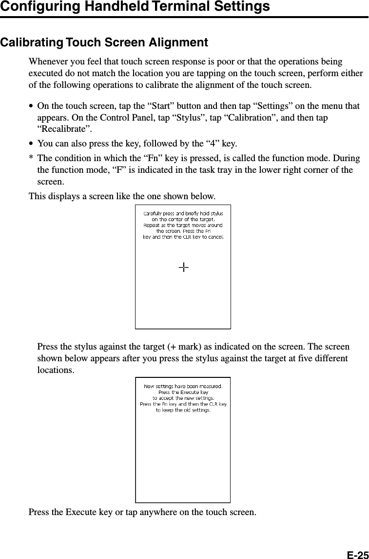
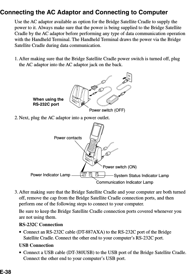
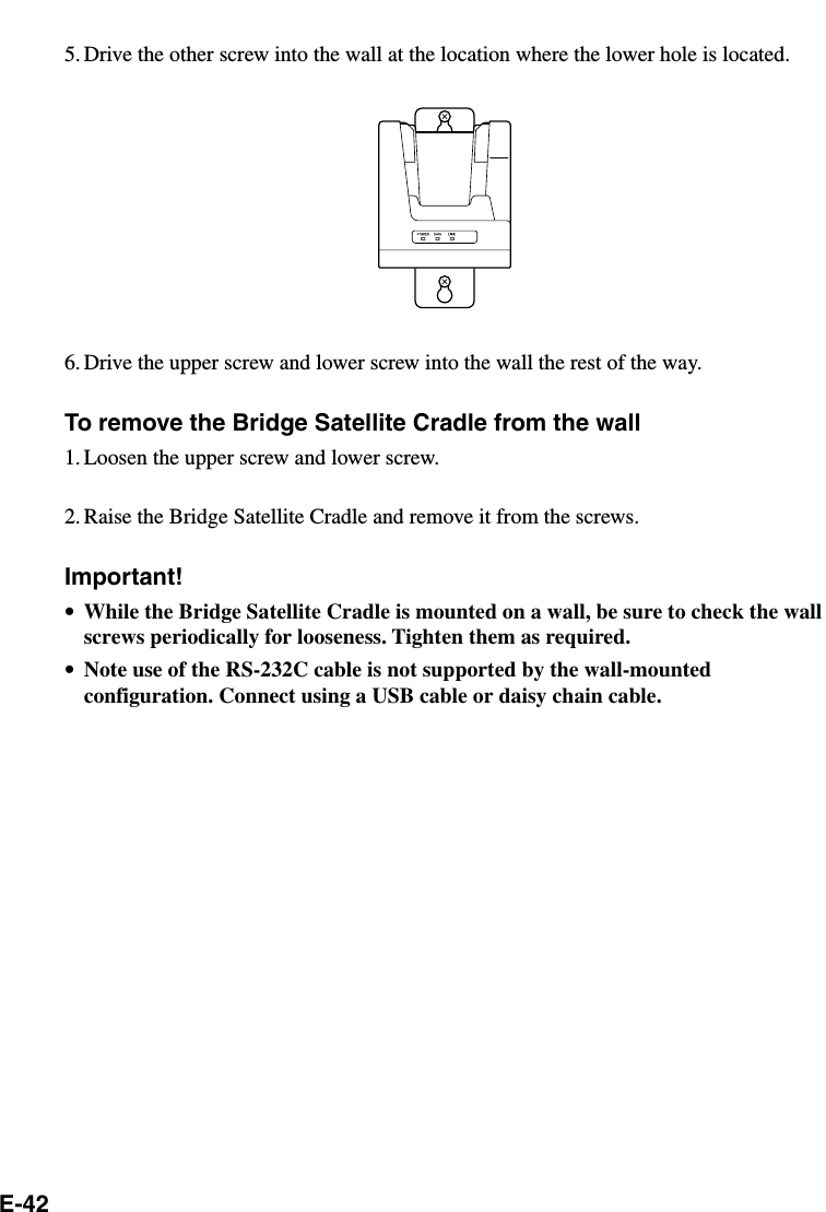
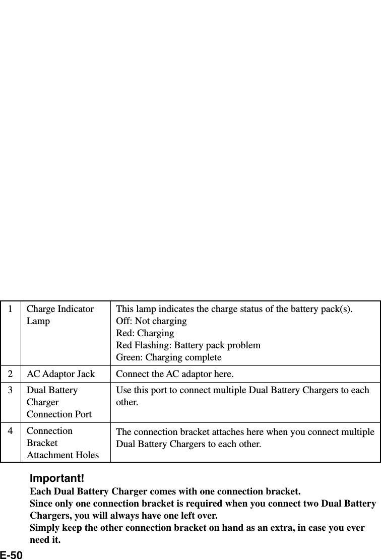
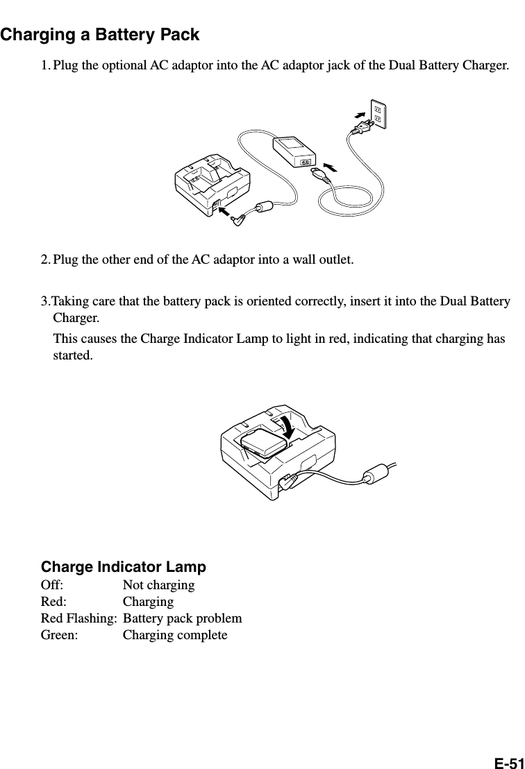
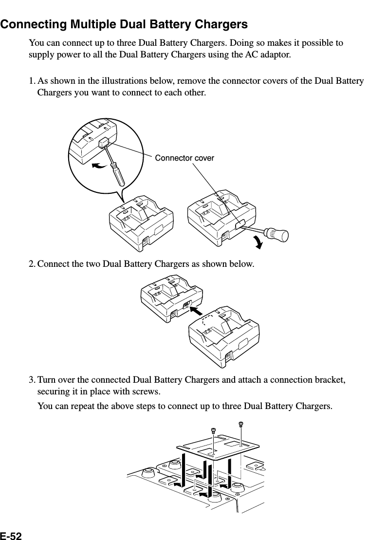
![E-26Adjusting Display ContrastPerform the following steps to adjust display contrast to make display colors more vividand easier to see.1. On the touch screen, tap the “Start” button and then tap “Settings” on the menu thatappears.2. On the Control Panel, tap “Contrast & Brightness”.3. On the dialog box that appears, tap the [Contrast] tab.4. Next, follow the instructions that appear on the display to adjust contrast.•You can also press the function key followed by the “2” key to perform adjustmentfor less contrast or the “3” key for more contrast. In order to continue to perform newadjustments of the contrast, please press the “Fn” key followed by the “2” or “3” keyonce again.* The condition in which the “Fn” key is pressed, is called the function mode. Duringthe function mode, “F” is indicated in the task tray in the lower right corner of thescreen.Adjusting Display BrightnessYou can use the following procedure to adjust screen brightness to make it easier toread under different lighting conditions.1. On the touch screen, tap the “Start” button and then tap “Settings” on the menu thatappears.2. On the Control Panel, tap “Contrast & Brightness”.3. On the dialog box that appears, tap the [Brightness] tab.4. Next, follow the instructions that appear on the display to adjust brightness.•You can also press the function key followed by the “5” key to perform adjustment ofthe brightness for a lighter display or the “6” key for a darker display. In order tocontinue to perform new adjustments of the display brightness, please press the “Fn”key followed by the “5” or “6” key once again.* The condition in which the “Fn” key is pressed, is called the function mode. Duringthe function mode, “F” is indicated in the task tray in the lower right corner of thescreen.Important!•If you use your Handheld Terminal in a location where it is hot, it automaticallydims the screen to protect against damage.](https://usermanual.wiki/Casio-Computer-Co/DT-X10M30URC/User-Guide-314033-Page-29.png)
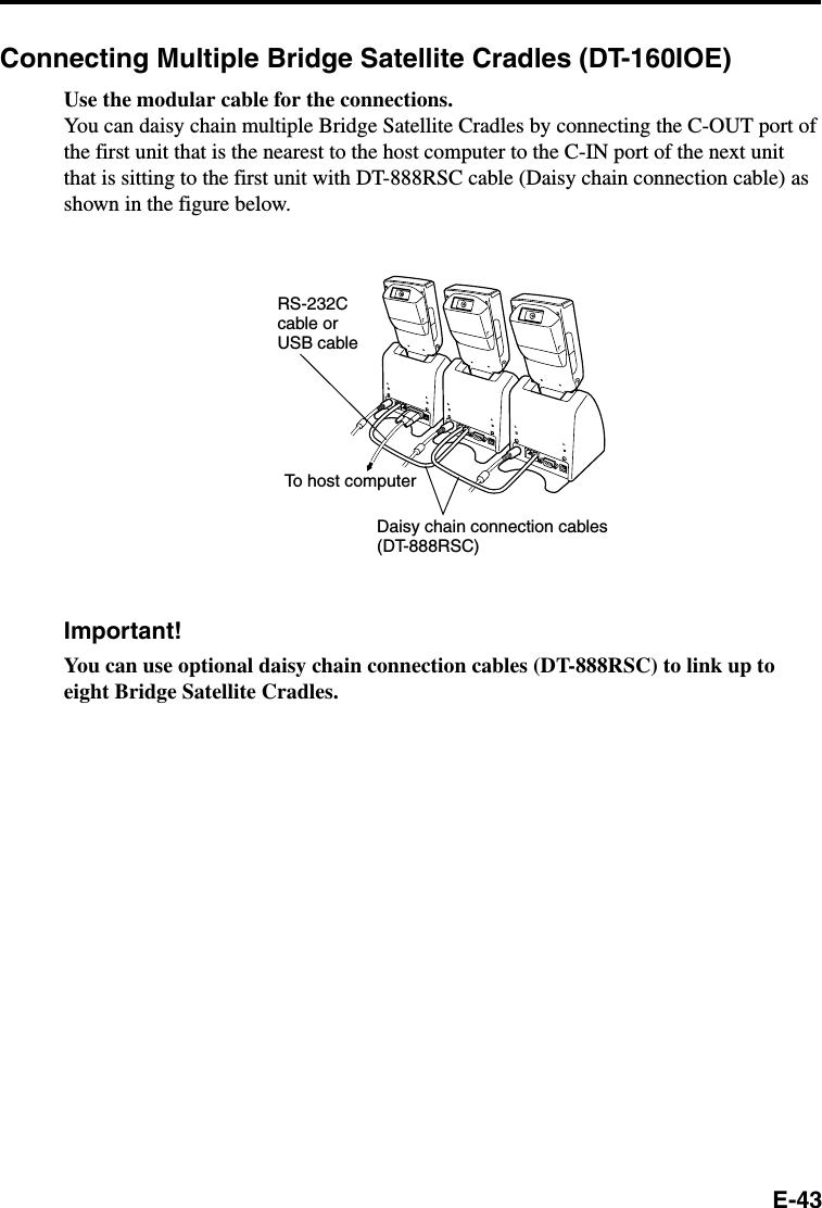
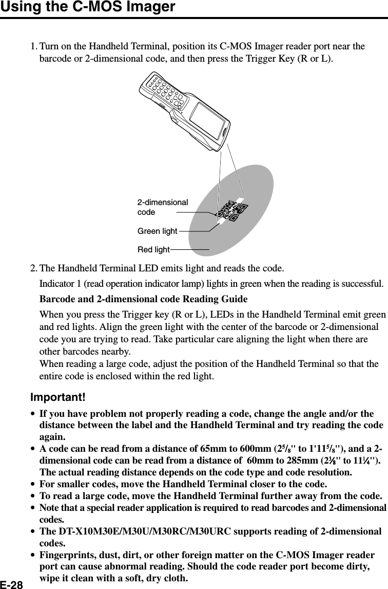
![E-27Display Auto DimmerThe display auto dimmer automatically lowers display brightness if you do not performany operation for a specific amount of time. This helps to conserve battery power.You can use the following procedure to specify the amount of that should be allowed topass before auto dimming is performed.1. On the touch screen, tap the “Start” button and then tap “Settings” on the menu thatappears.2. On the Control Panel, tap “Contrast & Brightness”.3. On the dialog box that appears, tap the [Backlight] tab.4. Next, follow the instructions that appear on the display to specify the auto dimmertime.](https://usermanual.wiki/Casio-Computer-Co/DT-X10M30URC/User-Guide-314033-Page-30.png)

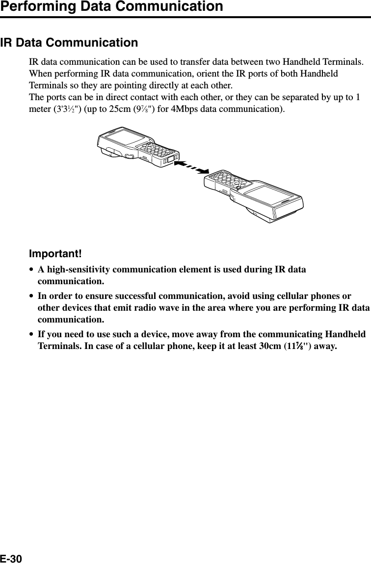
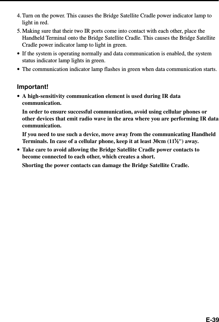
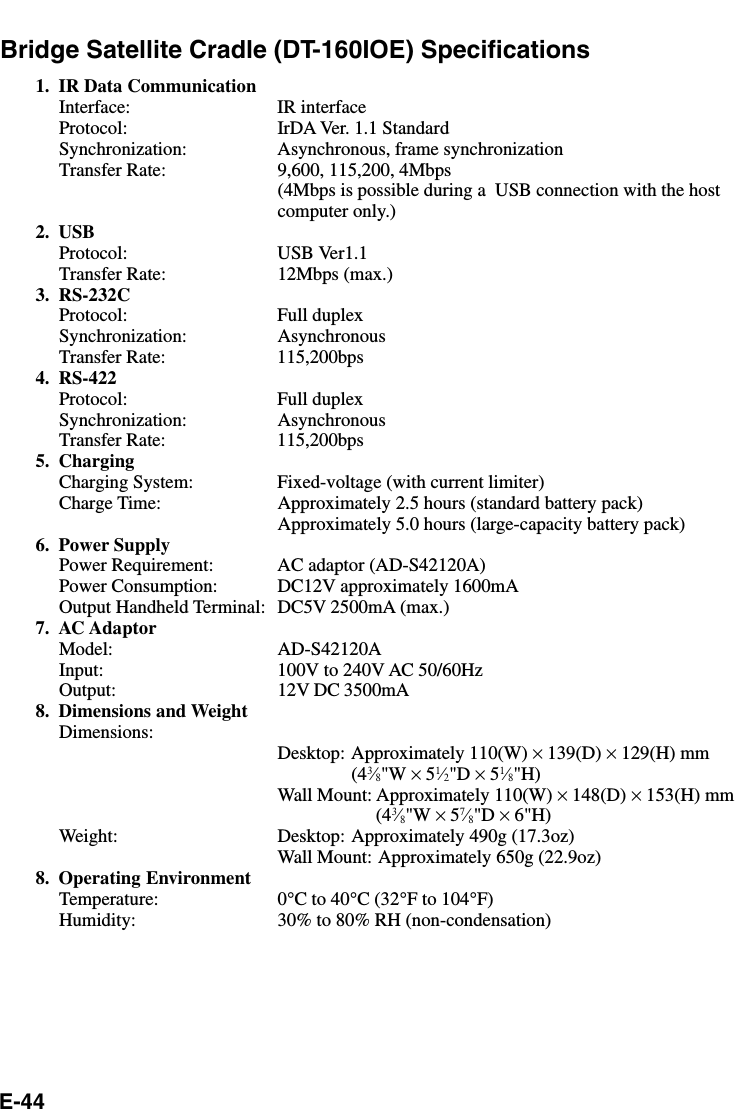
![E-32Resetting the Handheld TerminalResetting the Handheld Terminal is the same as restarting a computer. Performing areset causes all unsaved inputs and edits to be lost, but data that is already stored in thememory as well as all settings should be unaffected.Use reset to restore normal operation whenever the Handheld Terminal operatesabnormally due to misoperation or some other reason.Use the stylus to press the reset switch on the back of the Handheld Terminal.This starts the reset operation.If reset does not find a memory problemThe Handheld Terminal restarts, and normal operation is restored.If reset finds a memory problemA message like the one shown below appears on the display when the reset operationdiscovers a memory problem.When this message appears, press the R Trigger key to continue with the resetoperation. Note, however, that reset may not be successful depending on the conditionof the memory. In this case, perform the full reset operation described on the next page.Memory Corruption WarningA problem with memory contents has been found. Press [R trigger key] to continue with the reset procedure which restoresnormal system operation.Note that if the system determines that user memory cannot be repaired it will delete all user data currently in memory.See the User's Guide for details about initializing memory.FnR trigger keyL trigger key](https://usermanual.wiki/Casio-Computer-Co/DT-X10M30URC/User-Guide-314033-Page-35.png)
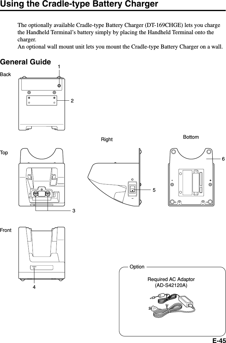
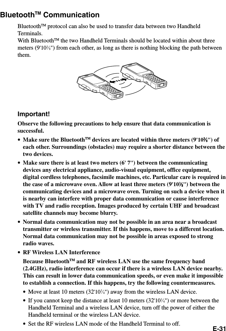
![E-33Performing a Full Reset (Initialization)Performing a full reset initializes memory. This means that all data stored in thememory (RAM) is deleted and all the settings are returned to their initial factorydefaults.Perform a full reset whenever any one of the following conditions exists.•When you want to delete all memory contents and return the settings to their initialfactory defaults.•When you are no longer able to use the Handheld Terminal because you forgot yourpassword.•When the Handheld Terminal does not operate normally due to a memory problem.•When the message “A problem with memory contents has been found. ...” appears.To perform a full resetImportant!Performing a full reset deletes all data currently stored in the memory (RAM). Ifpossible, backup data of the Handheld Terminal to a computer, Flash Memory, amemory card, or some other medium before performing a full reset.1. While the Handheld Terminal is turned on, hold down the power key and push downthe reset button for about one second, until the message shown below appears on thedisplay.•To cancel the reset operation, press the L Trigger key instead of the R Trigger key.2. Press the right Trigger key. This causes the message shown below to appear.•To cancel the reset operation, press the L Trigger key instead of the R Trigger key.3. Press the R Trigger key again.•This performs the full reset and deletes all data in the memory (RAM).•Press the R Trigger key again. This will cause the startup screen to appear.Memory All Clear WarningProceeding with this operation initializes memory.Press [R trigger key] to proceedor [L trigger key] to cancel.Memory All Clear WarningProceeding with this operation deletes all data stored in memory.Press [R trigger key] to proceedor [L trigger key] to cancel.FnR trigger keyL trigger keyFnR trigger keyL trigger key](https://usermanual.wiki/Casio-Computer-Co/DT-X10M30URC/User-Guide-314033-Page-36.png)