Casio Computer IT800A Handheld Terminal User Manual IT 800 Print E 100909
Casio Computer Co Ltd Handheld Terminal IT 800 Print E 100909
User manual
Handheld Terminal
㏚㒐仑䱾
Portatif Terminal
User’s Guide
䚷㏅尹㞝㢇
Kullanım Kılavuzu
Series
亊⎦
Serisi
Be sure to read “Safety
Precautions” inside this guide
before trying to use your Handheld
Terminal. After reading this guide,
keep it in a safe place for future
reference.
For product detail, refer also to
http://world.casio.com/system/
pa/UsersGuide/sup85_e.html
⢷ℎ䚷㏚㒐仑䱾Ὶ⏜Lj屚⑨ㅔ杀崏㢻
尹㞝㢇ᾼ䠓Đⴘ⋷㹷㊞‚榔đă杀崏
ⴛ䛱ῚㄛLj屚ⶖ㢻尹㞝㢇⬴✓Ⅼ⳧Lj
⁴∨⁙ㄛ╒冒ă
㢘⌂‶♐䠓嵵偕ⅰㇾLj嶆╵⪥║枔;
http://world.casio.com/system/pa/
UsersGuide/sup85_e.html
Portatif Terminali kullanmadan önce
kılavuzun içindeki “Güvenlik
Önlemlerini” okuyunuz.
Kılavuzu okuduktan sonra ileride
başvurmak için güvenli bir yere
kaldırınız.
Ürün detayları için ayrıca şuraya
başvurun
http://world.casio.com/system/pa/
UsersGuide/sup85_e.html
E C Tr
ᾼ⢌嵼
Türkçe English
JU.911`F`Izp2`5/joee!!!2 311:.9.31!!!:;56;14
Information in this document is subject to change without advance notice. CASIO Computer Co.,
Ltd. makes no representations or warranties with respect to the contents or use of this manual
and speci¿ cally disclaims any express or implied warranties of merchantability or ¿ tness for any
particular purpose.
BLUETOOTH is a registered trademark owned by Bluetooth SIG, Inc. and licensed to
CASIO COMPUTER CO., LTD.
Microsoft and Windows are either registered trademarks or trademarks of Microsoft
Corporation in the United States and/or other countries.
x
x
㢹偞‚⋗憩䥴
Lj
╾㢃㛈㢻㜖ⅰㇾ
ă
⓰嬎㲶崰䴦㣉㢘柟⋻▇ⶈ㢻㏚⌛⌔ⵈ㎥㢻㏚⌛䠓ℎ䚷
ᾜ⇩₊⃤⩿㞝㎥Ⅼ嵐
Lj
々ᾣⶈ䚷”₊⃤䐈䡽䠓䠓憑暏ㆶ㎥憑䚷ㆶ䠓㞝䫉㎥灧䫉䠓Ⅼ嵐
ᾜ‗㐎嶉
ă
x ŃōŖņŕŐŐŕʼn㞾㹷⌙⛕㮨Lj䉉ŃŭŶŦŵŰŰŵũġ ŔŊňLjŊůŤį㏏㙐㢘Lj㔗㲙⓰嬎㳟宗䴦㯮
㦹ゞ㢒䫍ℎ䚷封⛕㮨ă
x ŎŪŤųŰŴŰŧŵ☛ŘŪůťŰŸŴ㞾ㄽ恮⋻▇⢷儝⢚☛İ㎥⌅⢚ⵅ䠓㹷⌙⛕㮨㎥⛕㮨ă
Bu belgedeki bilgiler önceden bildirilmeksizin de÷iútirilebilir. CASIO Computer Co., Ltd. bu
kÕlavuzun içeri÷i veya kullanÕmÕyla ilgili hiçbir sorumluluk kabul etmez ya da garanti vermez
ve ticari de÷er veya belirli bir amaca uygunluk konusundaki açÕk ya da zÕmni her türlü garantiyi
reddeder.
BLUETOOTH, Bluetooth SIG, Inc. úirketinin sahip oldu÷u ve lisansÕ CASIO
COMPUTER CO., LTD'ye verilen tescilli bir ticari markadÕr.
Microsoft ve Windows ABD'de ve/veya baúka ülkelerde bulunan Microsoft Corporation'Õn
tescilli ticari ya da ticari markalarÕdÕr.
x
x
JU.911`F`Izp2`5/joee!!!3 311:.9.31!!!:;56;16

E-1
Contents
Safety Precautions .........................................................................................E-2
Operating Precautions ...................................................................................E-7
Important ........................................................................................................E-7
Regulatory Information ..................................................................................E-8
Handheld Terminal System Confi guration .................................................E-10
General Guide ...............................................................................................E-12
Loading and Removing the Battery Pack ...................................................E-14
Charging the Battery Pack ..........................................................................E-17
Handling the Hand Belt ................................................................................E-19
Connecting the Stylus String .......................................................................E-20
Attaching the Neck Strap.............................................................................E-21
Confi guring Handheld Terminal Settings ...................................................E-22
Adjusting the Laser Light Emission Width .................................................E-23
Handling microSD Cards .............................................................................E-25
Handling SIM Cards......................................................................................E-27
Handling SD Memory Cards ........................................................................E-29
Resetting the Handheld Terminal ................................................................E-30
Warning Label ...............................................................................................E-32
USB Cradle (HA-H60IO), Ethernet Cradle (HA-H62IO) ..............................E-33
Cradle-type Battery Charger (HA-H30CHG) ...............................................E-34
Car Mounted-type Battery Charger (HA-H35CHG)....................................E-34
Dual Battery Charger (HA-D32DCHG) ........................................................E-35
English
E-2
Safety Precautions
Congratulations upon your selection of this CASIO product. Be sure to read the
following Safety Precautions before trying to use it for the ¿ rst time.
Your neglect or avoidance of the warning and caution statements in the
subsequent pages causes the danger of ¿ re, electric shock, malfunction and
damage on the goods as well as personal injury.
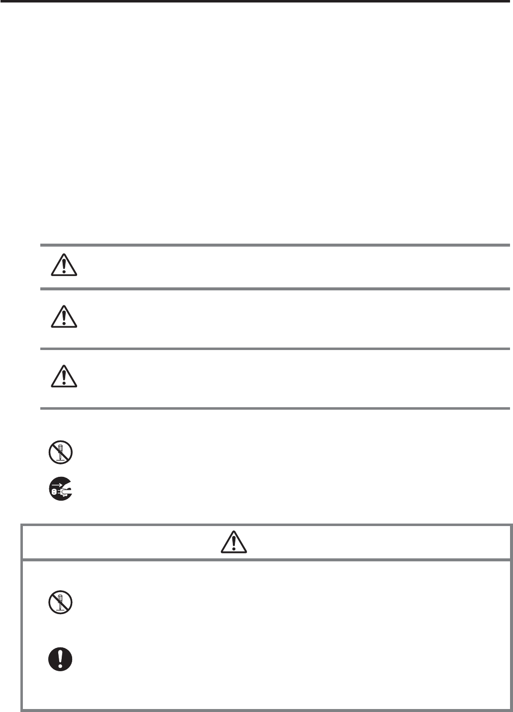
Markings and Symbols
The following are the meanings of the markings and symbols used in these Safety
Precautions.
Danger This symbol indicates information that, if ignored or applied
incorrectly, creates the danger of death or serious personal injury.
Warning
This symbol indicates information that, if ignored or applied
incorrectly, creates the possibility of death or serious personal
injury.
Caution
This symbol indicates information that, if ignored or applied
incorrectly, creates the possibility of personal injury or property
damage.
A diagonal line indicates something you should not do. The symbol shown
here indicates you should not try to take the unit apart.
A black circle indicates something you should do. The symbol shown here
indicates you should unplug the unit from the wall outlet.
Warning
Disassembly and Modifi cation
Never try to disassemble or modify the Handheld Terminal and its options
including battery pack and battery in any way.
Abnormal Conditions
Should the Handheld Terminal and/or its options including battery pack and
battery become hot or start to emit smoke or a strange odor, immediately turn
off the power and contact your dealer or distributor whom you purchased the
product from, or an authorized CASIO service provider.
x
x
x
x
E-3
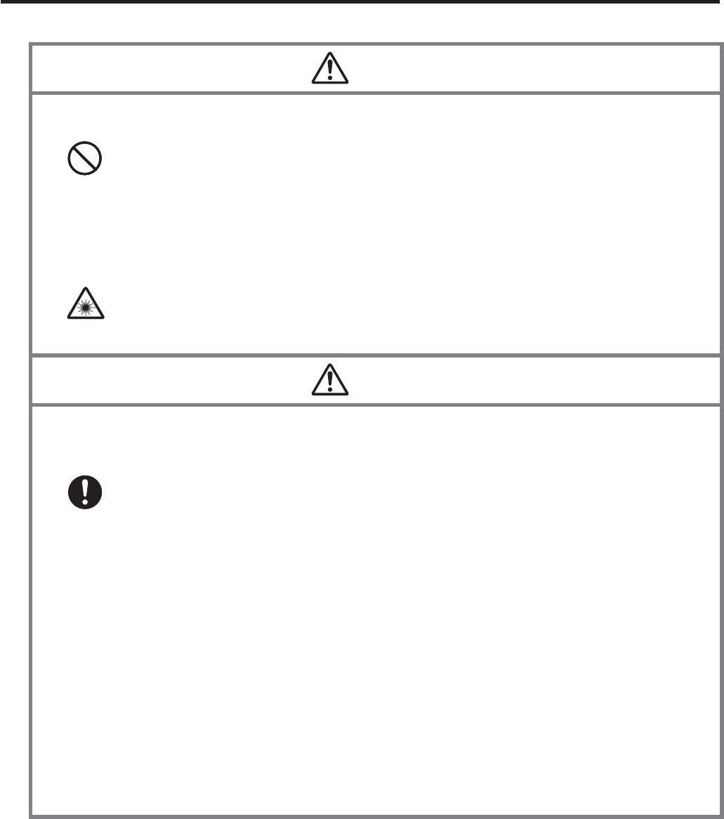
Warning
Dust and Moisture
Though the Handheld Terminal is dust and water splash resistant, its options
including the battery pack are not. Keep loose metal objects and containers
¿ lled with liquid away from your Handheld Terminal and the options. Also,
never handle the Handheld Terminal and the options while your hands are
wet.
Laser Light
The laser scanner models (model dependant) with the integrated laser
scanning module scan bar codes using laser light. Never look directly into
the laser light or shine the laser light into the eyes.
x
x
Warning
Interference with the Operation of Other Equipment
(Using Wireless Data Communication)
Keep your Handheld Terminal at least 22 centimeters (811/16") away from
anyone wearing a pacemaker. Radio waves emitted by the Handheld
Terminal can affect the operation of a pacemaker.
Before the use in aircraft, be sure to consult with cabin crew for interference
the Handheld Terminal emits.
Before the use in medical facility, be sure to consult with the facility
management or the manufacture of a speci¿ c medical equipment that the
Handheld Terminal may interfere with.
Do not use the Handheld Terminal nearby gas pump or chemical tank or any
other places À ammable or explosive.
To comply with the relevant European RF exposure compliance
requirements, a separation distance of at least 3.8cm in wireless operation
must be maintained between the terminal and all persons around. This
terminal must not be co-located or operating in conjunction with other
transmitter.
x
x
x
x
x
E-4
Caution
Foreign Objects
Take care to ensure that metals or combustible objects are not inserted into
the openings of the Handheld Terminal or its options, and not to allow
moisture to get inside of them.
Location
Install the cradle properly on a À at and stable surface so that it cannot fall
down onto À oor.
LCD Screen
Never apply strong pressure to the screen or subject it to strong impact.
Doing so can crack the LCD Screen.
x
x
x
Warning
Avoiding Traffi c Accidents
Never use your Car Mounted-type Battery Charger while operating a motor
vehicle. Park your vehicle in a safe place before performing any operation.
Never locate the Car Mounted-type Battery Charger where it might interfere
with proper operation of the vehicle.
Locate connecting cables as instructed by the manual, avoiding locations
that can interfere with driving operations.
Car Battery Power
Should the Car Power Cable become damaged, replace it immediately with
a new Car Power Cable when using the Car Mounted-type Battery Charger.
x
x
x
x
Caution
Installing in Vehicle
To save your vehicle’s battery from running down, be sure that the Car
Power Cable should be unplugged from the cigarette lighter socket when
you do not use the Car Mounted-type Battery Charger and that the use of
the battery charger should be avoid while the vehicle’s engine is turned off.
Do not handle the Car Power Cable with wet hands.
Install the Car Mounted-type Battery Charger at location in a vehicle where
strong vibration, unstable, excessive of humidity and dust, and under direct
sunlight can be avoid. Also, avoid the area where the air bag inÀ ates or any
other area where your safe driving is blocked.
Do not leave the Handheld Terminal in vehicle for a long period of time.
x
x
x
x
E-5
Optional Lithium-ion Battery Pack
Danger
Never use the Handheld Terminal and its option including the battery pack
and battery next to open À ame, near a stove, or any other area exposed to
high heat, or leave them for a long period of time in a vehicle parked in
direct sunlight.
Never use the battery pack with any device other than the Handheld
Terminal.
Never dispose of the battery pack by incinerating it or otherwise expose it
to heat.
Never transport or store the battery pack together with metal objects that
may result in shorting positive (+) and negative (–) terminals of the battery
pack. Be sure to place the battery pack in its case whenever transporting or
storing it.
Never throw the battery pack or otherwise subject it to strong impact.
Never pierce the battery pack with nails, hit it with a hammer, or step on it.
Use only the speci¿ ed battery charger to charge the battery pack.
x
x
x
x
x
x
x
Warning
Never place the battery pack in a microwave oven or any other high-voltage
device.
If the amount of time period the battery pack can serve becomes
considerably short even after it has been fully charged for the speci¿ ed time
period, stop using it.
Should the battery pack start to leak or emit a strange odor, immediately
move it away from any À ame nearby. Leaking battery À uid is combustible.
Should À uid from the battery pack accidentally get into your eyes or on the
skin, do not rub it. Immediately rinse it off with clean tap water and then
consult a physician.
x
x
x
x
Caution
Replace only with the same type of battery pack recommended by CASIO.
Dispose of used battery packs according to the local regulation.
Keep the battery pack out of the reach of small children.
x
x
E-6
Power Supply / AC Adaptor
Warning
Do not use the Handheld Terminal at a voltage other than the speci¿ ed
voltage. Also, do not connect the Handheld Terminal to a multi-plug power
strip.
Never modify, sharply bend, twist, or pull on the power cord.
Never use a detergent to clean AC adaptor and its power cable, especially
on the plug and the jack.
When using the battery chargers and the cradles, be sure to use the
respective AC adaptors.
x
x
x
x
Caution
Never pull on the power cord when unplugging it. Always hold the plug
when unplugging it from the wall outlet.
Never touch the plug while your hands are wet.
Be sure to unplug the power cord from the wall outlet before cleaning the
battery chargers and the cradles.
Unplug the power cord from the wall outlet whenever leaving the battery
chargers and the cradles unattended for a long period.
The housing of the AC adaptor can become warm during normal use.
At least once a year, unplug the AC adaptor from the wall outlet and clean
any dust that builds up between the prongs of the plug.
Dust built up between the prongs can lead to the danger of ¿ re.
x
x
x
x
x
x
Backup of All Important Data
Caution
Note that CASIO Computer Co., Ltd. shall not be held liable to you or any
third party for any damages or loss caused by deletion or corruption of data
due to use of the Handheld Terminal, malfunction or repair of the Handheld
Terminal or its peripherals, or due to the batteries going dead.
The Handheld Terminal employs electronic memory to store data, which
means that memory contents can be corrupted or deleted if power is
interrupted due to the batteries going dead or incorrect battery replacement
procedures. Data cannot be recovered once it is lost or corrupted. Be sure
to make backup of all important data. One way to do this is to use the
separately sold cradles to transfer data to a computer.
x
x

E-7
Operating Precautions
Your Handheld Terminal and its options are precision. Improper operation or rough
handling can cause problems with data storage and other problems. Note and observe
the following precautions to ensure proper operation.
Do not leave dead battery pack in the Handheld Terminal for a long period.
Dead battery pack can leak, leading to malfunction and damage to the Handheld
Terminal.
Stop or avoid using the Handheld Terminal and its options in areas and
conditions subject to the following.
— Large amounts of static electricity
— Extreme heat or cold or humidity
— Sudden temperature change
— Large amount of dust
— After large amount of rain or water falls on the Handheld Terminal
— Pressing the screen or keys with excessive force when using in the rain
Dead Pixels
The LCD panel employed in this product uses high precision and substantial number
of components which commonly cause a small number of the pixels not to light or
to remain lit all the time. This is due to the characteristics of LCD panel yield in
accuracy over 99.99% and permissible.
802.11a Restrictions:
— This product is for indoor use only when using channels 36, 40, 44, 48, 52, 56, 60,
or 64 (5150-5350 MHz).
— To ensure compliance with local regulations, be sure to select the country in which
the access point is installed.
Important
This guide does not include any information about programming and download
procedures. See the applicable separate documentation for information about the
procedures.
After Service
Should this product ever malfunction, contact your original retailer providing
information about the product name, the date you purchased it, and details about the
problem.
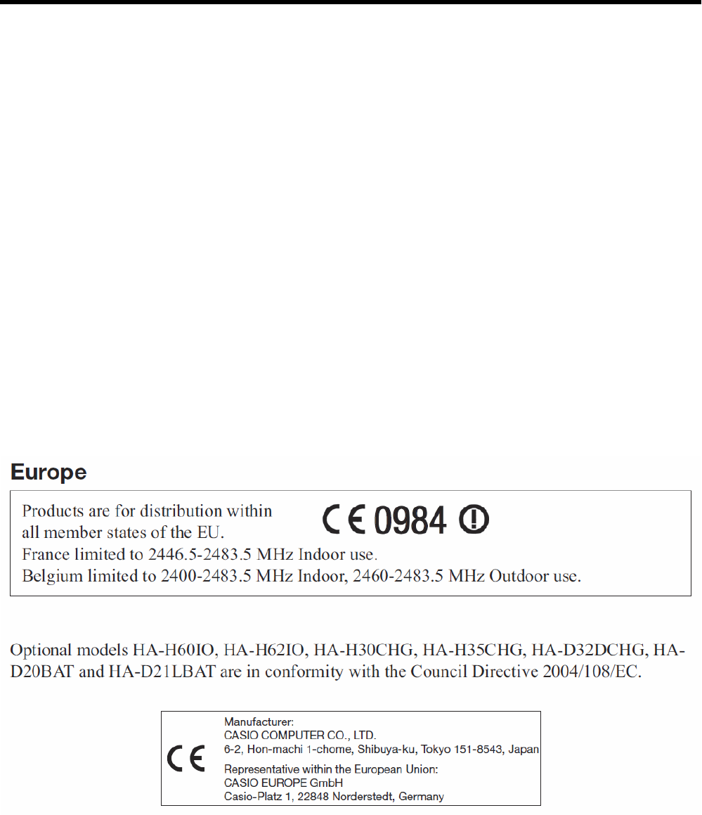
This mark applies to EU countries and Turkey only.
x
x
x
x
x
x

E-8
Regulatory Information
The USA and Canada
GUIDELINES LAID DOWN BY FCC RULES FOR USE OF THIS UNIT IN THE U.S.A. (not
applicable to other areas).
NOTICE
This equipment has been tested and found to comply with the limits for a Class B digital device, pursuant
to Part 15 of the FCC Rules. These limits are designed to provide reasonable protection against harmful
interference in a residential installation. This equipment generates, uses and can radiate radio frequency
energy and, if not installed and used in accordance with the instructions, may cause harmful interference
to radio communications. However, there is no guarantee that interference will not occur in a particular
installation. If this equipment does cause harmful interference to radio or television reception, which can
be determined by turning the equipment off and on, the user is encouraged to try to correct the interference
by one or more of the following measures:
Reorient or relocate the receiving antenna.
Increase the separation between the equipment and receiver.
Connect the equipment into an outlet on a circuit different from that to which the receiver is connected.
Consult the dealer or an experienced radio/TV technician for help.
FCC WARNING
Changes or modi¿ cations not expressly approved by the party responsible for compliance could void
the user’s authority to operate the equipment.
Proper connectors must be used for connection to host computer and/or peripherals in order to meet FCC
emission limits.
Caution Exposure to radio frequency radiation (below is for portable device)
To comply with FCC RF exposure compliance requirements, this device must not be co-located or
operating in conjunction with any other antenna or transmitter.
•
•
•
•
Declaration of Conformity
Model Number: HA-H60IO, HA-H62IO
Trade Name: CASIO
Responsible party: Industrial Handheld Division
Casio America, Inc.
Address: 570 Mt. Pleasant Avenue, Dover, New Jersey 07801, USA
Telephone number: 973-361-5400
This device complies with Part 15 of the FCC Rules. Operation is subject to the following two conditions:
(1) This device may not cause harmful interference, and (2) this device must accept any interference
received, including interference that may cause undesired operation.
For Users in Canada
These Class B digital apparatuses comply with Canadian ICES-003.
Cet appareil numériqué de la classes B est conformé à la norme NMB-003 du Canada.
These devices comply with RSS 210 of Industry Canada (IC).
Operation is subject to the following two conditions:
(1) These devices may not cause interference, and
(2) These devices must accept any interference, including interference that may cause undesired opera-
tion of this device.
L ‘ utilization de ce dispositif est autorisée seulement aux conditions suivantes :
(1) il ne doit pas produire de brouillage et
(2) l’ utilisateur du dispositif doit étre prêt à accepter tout brouillage radioélectrique reçu, même si ce
brouillage est susceptible de compromettre le fomctionnement du dispositif.
Exposure to Radio Frequency Radiation:
To comply with IC RF exposure compliance requirements, the antenna(s) used for this transmitter must
not be collocated or operating in conjunction with any other antenna or transmitter, except in
accordance with IC multi-transmitter product procedures.
For Users in the USA and Canada
This device is restricted to indoor use due to its operation in the 5.15 to 5.25 GHz frequency range.
FCC/IC requires this product to be used indoors for frequency range 5.15 to 5.25 GHz to reduce the
potential for harmful interference to co-channel Mobile Satellite systems. High power radars are
allocated as primary users of the 5.25 to 5.35 GHz and 5.65 to 5.85 GHz bands. These radar stations
can cause interference with and/or damage this device.
E-9
E-10
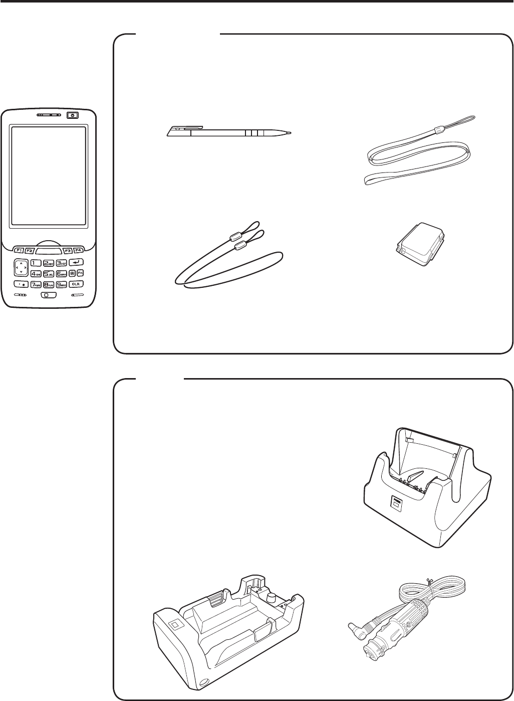
Handheld Terminal System Confi guration
Please check the items in the box before using the Handheld Terminal
for the fi rst time.
Handheld Terminal
User's Guide (this manual)
Bundled Items
IT-800 Series
IT-800 Series
Neck StrapStylus
The stylus can be attached
to the hand belt.
Large-capacity Battery
Pack Cover
Stylus String
The stylus string can be
attached to the stylus
and hand belt.
Options
USB Cradle
HA-H60IO
Car Mounted-type Battery Charger
HA-H35CHG
Ethernet Cradle
HA-H62IO
Cradle-type Battery Charger
HA-H30CHG
The illustration shows the
USB Cradle (HA-H60IO).
The car power cable accompanies
to HA-H35CHG.
For the latest options list, refer to the ON-LINE manual available at
http://world.casio.com/system/pa/UsersGuide/sup85_e.html
The hand belt
is attached on
the back of the
terminal. Set the
hand belt in proper
length by adjusting
the hook-loop
fastener prior to
using the terminal.
IT-800EC-05
IT-800EC-35
These models are
available in the
USA and Canada
only.
E-11
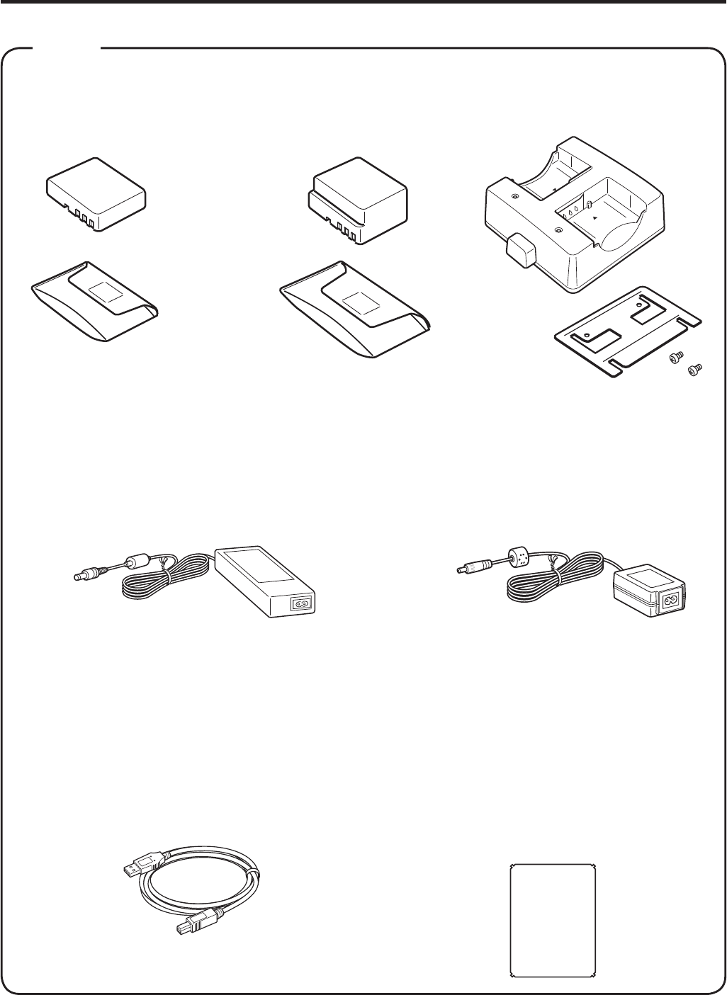
HA-D21LBAT/HA-D21LBAT-A
(Large-capacity Battery Pack)
Power Cord for Europe AC-CORD-EU
Power Cord for North America AC-CORD-US
Power Cord for Taiwan AC-CORD-TW
Power Cord for Korea AC-CORD-KR
Power Cord for Australia AC-CORD-AU
HA-D20BAT/HA-D20BAT-A
(Battery Pack)
Dual Battery Charger Battery Pack
AC Adaptor for USB Cradle/
Ethernet Cradle/
Dual Battery Charger
AD-S42120B-N
Options
Cable DT-380USB
HA-D32DCHG
Screen Protect Sheet
HA-C90PS5B
AC Adaptor for IT-800/
Cradle-type Battery Charger
AD-S15050B-N
For WWAN models*, be sure to use either HA-D20BAT-A or
HA-D21LBAT-A battery pack.
* WWAN models:
IT-800RGC-05/RGC-15/RGC-35
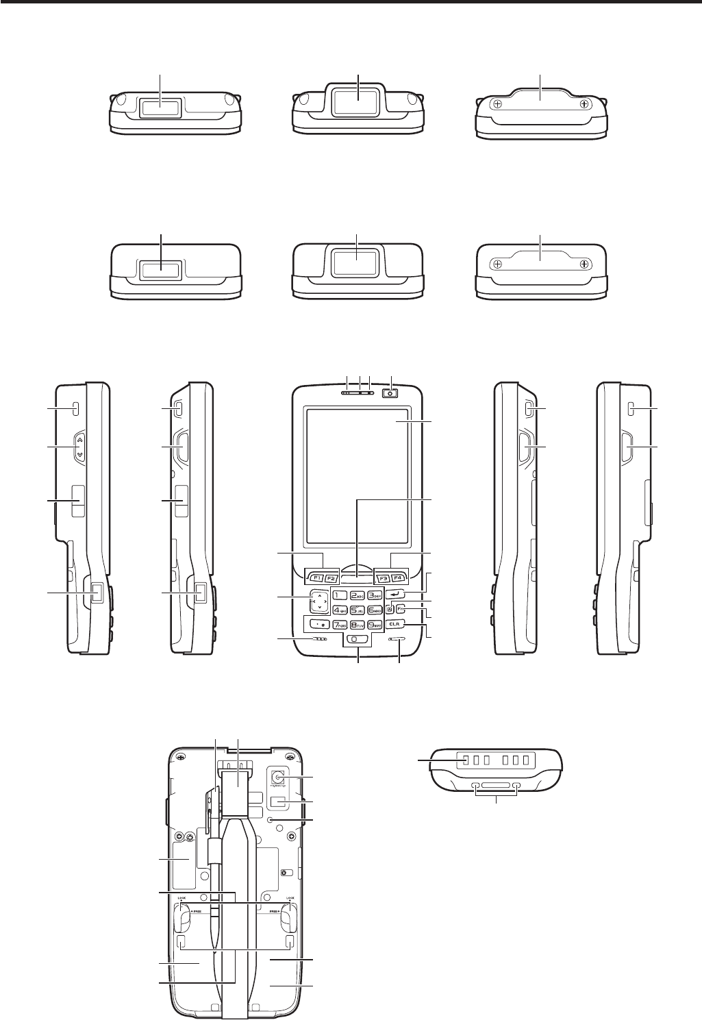
E-12
General Guide
Back Bottom
23
24
26
27
28
29
31
32
33 34
30
22
21
Left Right
25
17
18
20
Front
123 4
5
6
8
9
10
11
12
13
14
15
77
25
16
25
17
18
20
25
16
19
IT-800RGC-05
19
IT-800R-05
IT-800EC-05
19
IT-800RGC-15
IT-800R-15
IT-800RC-15
19
Top
19
IT-800R-35
IT-800A-35
IT-800EC-35
IT-800RC-35
19
IT-800RGC-35
Model: IT-800A-35U

E-13
1 Receiver 12 Numeric Keys 23 Camera Lens (Camera models)
2 Indicator 1 13 Cursor Key 24 LED (Camera models)
3 Indicator 2 14 Microphone 25 Car Mounted-type Battery
Charger Mount Holes
4 Power Key 15 Speaker 26 Reset Switch
5 Screen* 16
R Trigger Key
27
microSD Card Slot
(for IT-800R-15/RC-15/RGC-15/
R-35/A-35/RC-35/RGC-35/EC-05)
R Enter Key
(for IT-800R-05/EC-05/
RGC-05)
6
Center Trigger Key
17
L Trigger Key
28 Battery Pack Cover
Center Key
(for IT-800R-05/EC-05/
RGC-05)
Up/Down Key
(for IT-800R-05/EC-05/
RGC-05)
7 Function Keys 18 DC Jack 29 Cradle Mount Holes
8 Enter Key 19
Barcode Reader 30
N/A
(for IT-800RGC-05/RGC-15/
RGC-35)
N/A
for IT-800R-05/EC-05/
RGC-05)
31 Battery Pack Cover Lock
Switches
9 Mode Key 20 IR Port 32 Extension Port
10 Fn Key 21
Power/Signal Terminals
33 Stylus
11 CLR Key 22 Strap Holes 34 Hand Belt
* Antenna of the NFC is laid underneath of the screen frame for communication with card.

E-14
Loading and Removing the Battery Pack
Your Handheld Terminal uses two types of battery: a battery pack and a memory
backup battery.
The battery pack is used to power normal operations and to store data, while the
memory backup battery provides the power required to maintain memory contents
when the battery pack power is unable to supply power for some reason.
You can choose either battery pack (HA-D20BAT, HA-D20BAT-A) or large-capacity
battery pack (HA-D21LBAT, HA-D21LBAT-A) for operating power.
For WWAN models, be sure to use either HA-D20BAT-A or HA-D21LBAT-A battery pack.
The backup battery is installed inside of the Handheld Terminal.
This guide uses the following terms to refer to the batteries.
Battery Pack:
Rechargeable battery pack (HA-D20BAT, HA-D20BAT-A, HA-D21LBAT
or HA-D21LBAT-A) for normal operations and data storage
Backup Battery: Built-in battery for memory backup
When the battery pack power goes low, immediately charge it or replace it with a
charged battery pack.
You can use the Dual Battery Charger, the Cradle-type Battery Charger, the USB Cradle,
the Ethernet Cradle, the Car Mounted-type Battery Charger, or the AC adaptor to charge
a battery pack installed in the terminal. See the relevant sections in this guide for the
respective options about how to use.
Important!
Always keep backup of all important data!
The battery pack powers normal operation and also provides power required to
maintain memory contents, while the backup battery provides backup power to
maintain memory contents. Because of this, you should not remove the battery
pack if the backup battery is dead. Removing the battery pack while the backup
battery is dead causes data in the memory to be corrupted or lost. Note that
once data is lost it cannot be recovered. Always keep backup of all important
data.
The charge of a battery pack when you purchase it may be depleted due to
testing at the factory or natural discharge during shipment and storage. Be sure
to charge the battery pack before you use it.
The life of a battery pack is limited, and charging a battery pack causes it to
gradually lose its ability to maintain the charge. If your battery pack seems to
require charging very frequently, it probably means it is time to purchase a new one.
If a battery pack is used past the end of its service life, it may swell up in size. In
such a case, replace the battery pack with a new one.
When the battery pack is attached, it takes 30 minutes for the backup battery to
obtain enough charge for maintaining memory (RAM) contents for 10 minutes.
It takes four days for the backup battery to achieve a full charge.
x
x
x
x
x
E-15
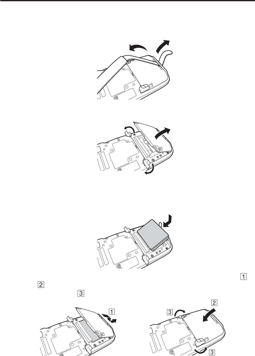
Loading
1. Turn the terminal upside down and loosen the hand belt.
.1%-
(4''
2. Slide the left and right lock switches for the battery pack cover to the “FREE”
position, and then remove the battery pack cover.
.1%-
(4''
.1%-
(4''
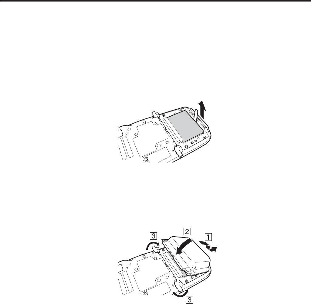
3. Load a battery pack (HA-D20BAT, HA-D20BAT-A) or large-capacity battery pack
(HA-D21LBAT, HA-D21LBAT-A). Take care that the battery pack is oriented
correctly when you load it. In addition, load the battery pack while making sure that
the end of the battery pack removal tape is protruding above the battery pack.
.1%-
(4''
.1%-
(4''
4. Put back the battery pack cover in the compartment as instructed by the arrows,
and in the illustration and then return the battery pack cover lock switches to the
“LOCK” position ( ).
E-16
Removing
1. Make sure that the Handheld Terminal is turned off.
If the power is on, press the power key to turn it off.
2. Turn the terminal upside down and loosen the hand belt.
3. Refer to “Loading” on the previous page and remove the battery pack cover.
4. Remove the battery pack by pulling up the removal tape as shown in the illustration.
Loading the large-capacity battery pack into the Handheld Terminal
After loading the large-capacity battery pack, you need to use the special large-capacity
battery pack cover in place of the standard battery pack cover.
“Loading and Removing” of the large-capacity battery pack cover is the same as those
for the standard battery pack cover.
Important!
When removing the battery pack, make sure you do not leave the Handheld
Terminal without a battery pack for more than about 10 minutes. Doing so can
cause data in the memory to be deleted.
When removing the battery pack, be sure you carefully follow the proper
procedure as explained in this guide.
Never try to use other type of battery than the ones that are speci¿ ed for this
product.
When removing the battery pack, pull the removal tape straight up and remove
the battery pack. Removing with excessive force can damage the battery pack.
Before starting to use the Handheld Terminal, ensure that the battery pack cover
is properly closed. If not, the power is not turned on or is turned off abruptly
while it is in use.
x
x
x
x
x
E-17
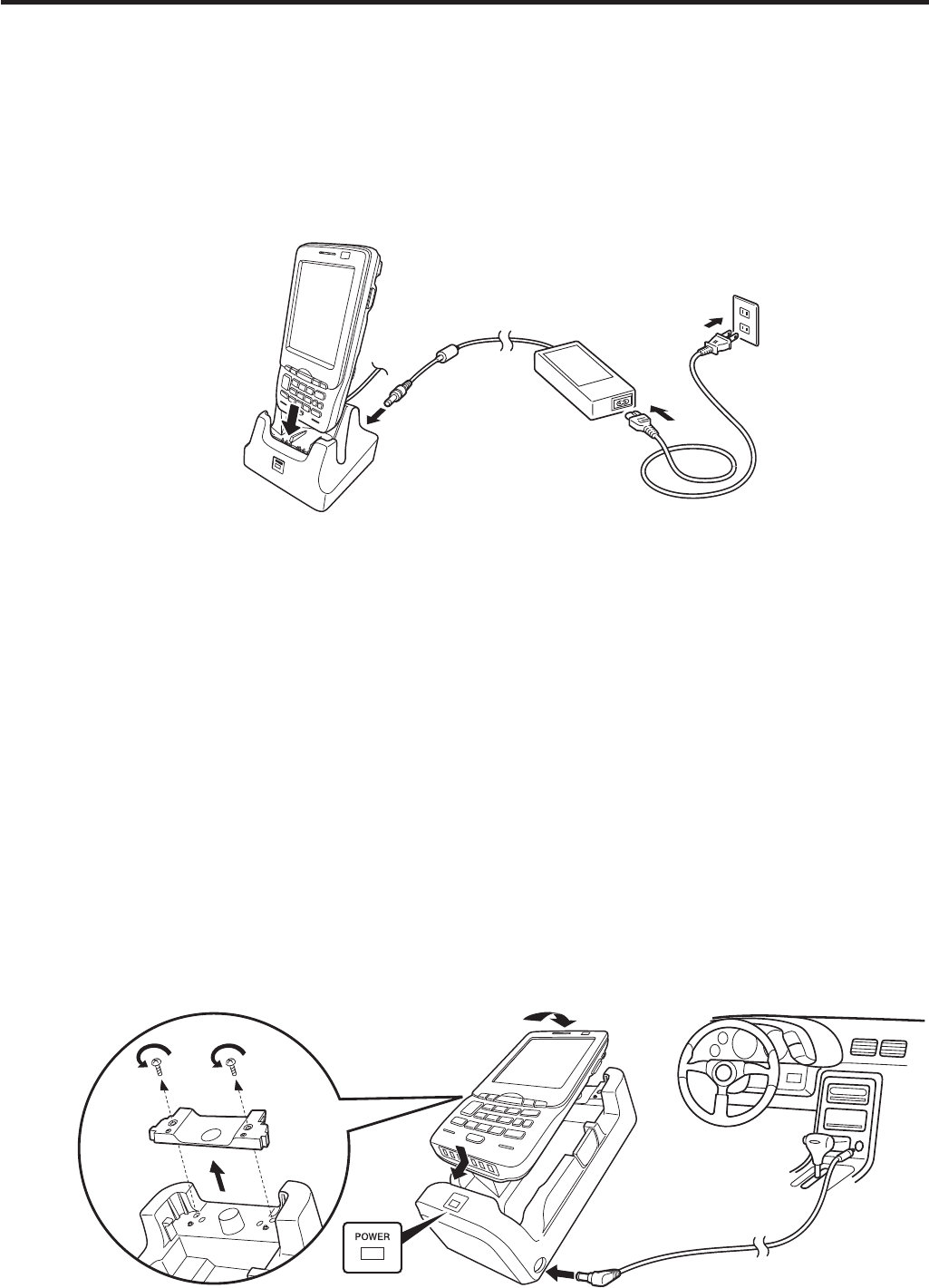
Charging the Battery Pack
Battery pack installed in the terminal can be charged using either cradle, battery
charger or AC adaptor (AD-S15050B). Battery charge condition can be monitored with
Indicator 1 on the terminal. Multiple battery packs can also be charged simultaneously
using Dual Battery Charger.
USB Cradle/Ethernet Cradle/Cradle-type Battery Charger
AD-S42120B
Status of Indicator 1 on IT-800:
Orange: Charging
Red: Standby due to battery pack error or the surrounding temperature is out of the
charging temperature range
(charging begins when the temperature is within the charging temperature range)
Green: Charging complete
Car Mounted-type Battery Charger
Before the use of the Car Mounted-type Battery Charger for WWAN models, remove a
small plate (see the ¿ gure below) on the charger.
For other models, you do not need to remove the plate. Proceed the step below.
Plug in the Car Power Cable accompanied in the box to the Car Mounted-type Battery
Charger as illustrated below and the other end to the cigarette lighter socket in vehicle.
The power LED on the front of the Car Mounted-type Battery Charger will light green
if the Handheld Terminal has been properly mounted.
Status of Indicator 1 on IT-800:
Refer to “USB Cradle/Ethernet Cradle/Cradle-type Battery Charger” above.
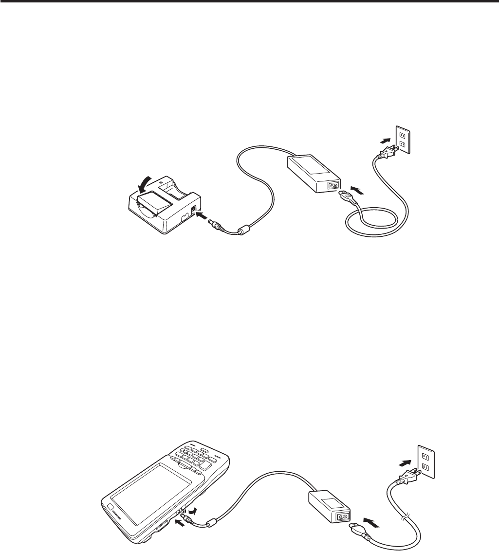
E-18
Dual Battery Charger
Taking care that the battery pack is oriented correctly, insert it into the Dual Battery
Charger.
This causes the Charge Indicator LED to light in red, indicating that charging has
started.
AD-S42120B
You can connect up to three Dual Battery Chargers.
Status of Charge Indicator LED
Off: Not charging
Red: Charging
Red Flashing: Battery pack problem
Green: Charging complete
Green Flashing: Standby due to the surrounding temperature being beyond the
speci¿ ed temperature range (Approximately 0°- 40°C) (charging
resumes when the temperature reaches the range.)
AC Adaptor
AD-S15050B
Status of Indicator 1 on IT-800:
Refer to “USB Cradle/Ethernet Cradle/Cradle-type Battery Charger” on the previous
page.
E-19
Handling the Hand Belt
The hand belt is attached to the terminal. Remove it if it is not necessary.
To remove the hand belt
1. As shown in the ¿ gure, pull out the metal part of the hook while pressing down the
protrude part that has a small dimple on it.
2. Loose the hook-loop fastener and then pull out the belt through the hand belt hook as
shown in the ¿ gure.
To attach the hand belt
1. Thread one end of the hand belt through the hand belt hook. Then fold it back and set
the belt in proper length by adjusting the hook-loop fastener.
2. As shown in the ¿ gure, align the metal part of the hand belt hook in line with the
installation position on the terminal and then snap it into the ditch. Make sure that the
metal part is ¿ rmly seated.
E-20
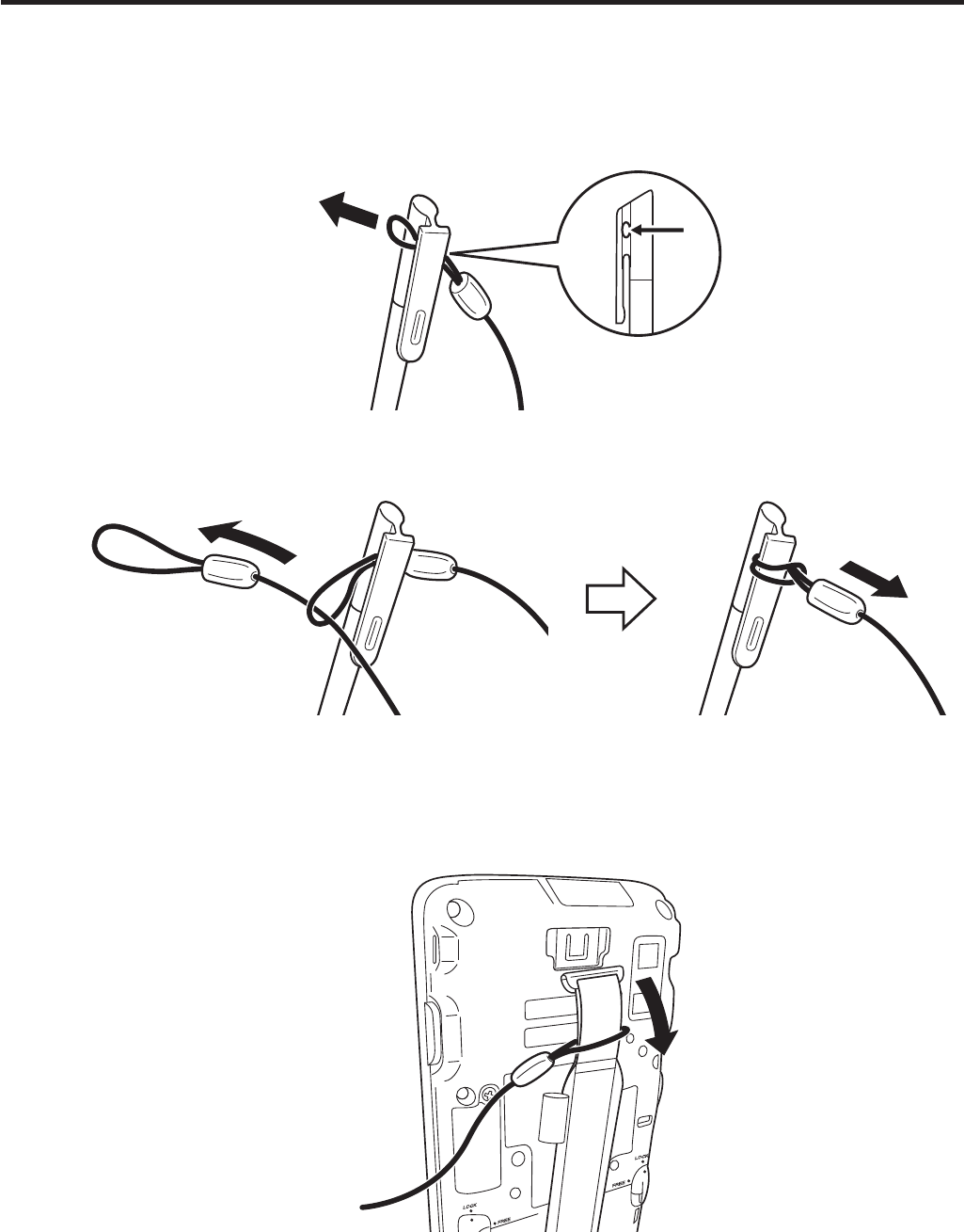
Connecting the Stylus String
The string can be connected to stylus and hand belt to prevent loss of stylus or
misplacing. Follow the instruction below to connect it to stylus and hand belt.
1. Thread one end of the string through the slit on stylus as shown in the illustration.
2. Thread the other end of the string through the loop as shown in the illustration, and
then pull the other end to tighten.
3. Unhook one end of the hand belt from IT-800 if it is attached, and then thread the
hand belt through the loop of the string as shown in the illustration.
For unhooking the hand belt from the terminal, refer to “To remove the hand belt” on
page 19.
4. Hook the end of the hand belt to the terminal. Refer to “To attach the hand belt” on
page 19.
E-21
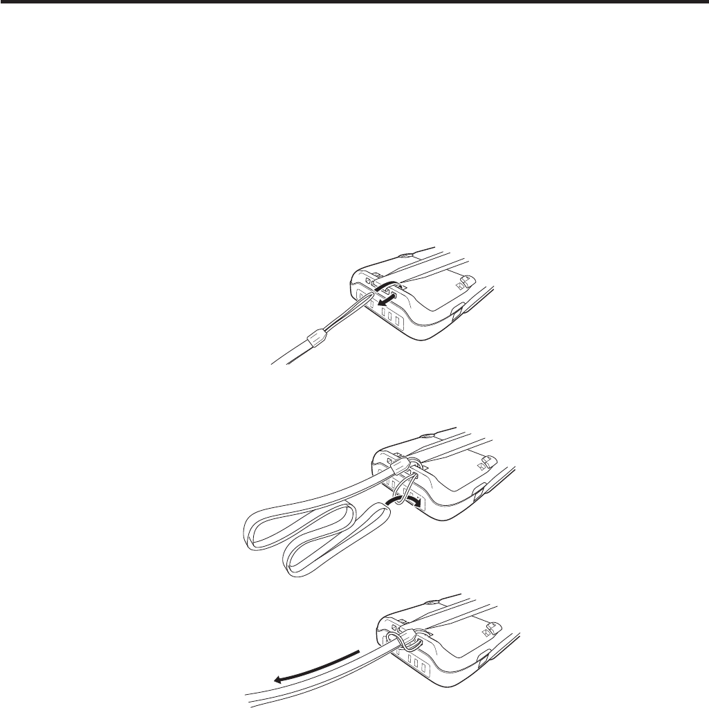
Attaching the Neck Strap
The neck strap can be used to prevent the Handheld Terminal from fall when carrying
it around. Since there are two strap holes where the neck strap can be attached, use
the hole that affords the ease of use. Attach the neck strap according to the procedure
described below.
To attach the neck strap
1. Pass the thin cord of the neck strap through the strap hole on the back of the
Handheld Terminal.
2. Pass the other end of the strap (the part you put around your neck) through the loop
formed by the thin cord.
Important!
Do not swing the Handheld Terminal around holding the neck strap.

E-22
Confi guring Handheld Terminal Settings
Calibrating Touch Screen Alignment
Whenever the response of the touch screen is poor, or operation being executed does
not match with the location you are tapping on the touch screen, please recalibrate the
alignment of the touch screen using the following method.
Press the “Fn” key and then press the “4” key after con¿ rming that “F” is displayed
in the lower right corner of the screen. The following screen is displayed.
You can also display this screen by navigating as follows:
Start Settings System Screen Align Screen
Press the stylus against the center of the target mark (+ mark) as indicated on the
screen.
After the calibration is complete, the terminal resumes a screen automatically
according to the method carried out to initiate the calibration.
If you start the calibration by pressing "Fn" and "4" keys, the terminal resumes Start
screen, or General tab screen of Settings mode which is the screen one before align
screen of Settings mode if you initiate by navigating to the icons.
x
x
E-23
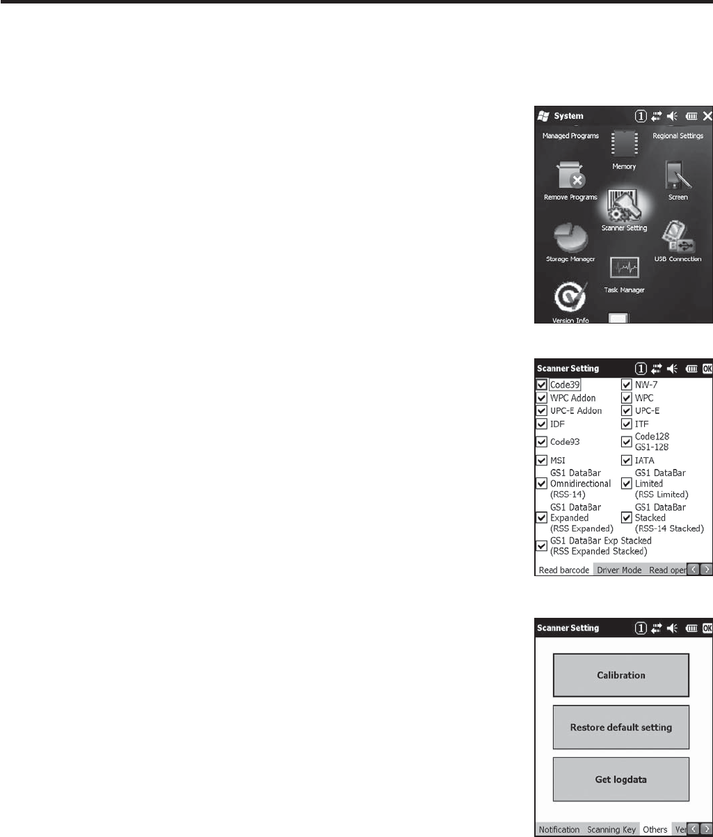
Adjusting the Laser Light Emission Width
The emission width of the laser light emitted by the Handheld Terminal (model
dependant) can be adjusted. Adjust the emission width when it is improper.
1. Navigate to the menus in the following sequence:
Start Settings System
The Control Panel appears as shown in the screen.
2. Tap the [Scanner Setting] icon. The Setting screen
appears as shown in the screen.
3. Tap the [Others] tab in the Scanner Setting screen.
E-24
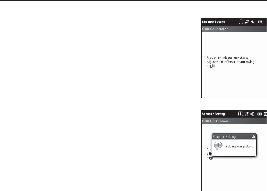
4. Tap the [Calibration] button. The display appears as
shown at right.
5. Press the trigger key to emit laser light, and align the
light with the barcode for adjusting emission width.
Align the laser light with the narrow bars on both sides.
The message appears as shown at right when adjustment
is completed.
Repeat the setting if “Setting failed” message appears.
Emission Width Adjustment Bar code
x
x
x
E-25
Handling microSD Cards
The Handheld Terminal supports microSD card.
The employment of microSD card slot is dependent on model. See page 13 for the
models with microSD card slot integrated.
Since the microSD card slot is located inside the battery pack compartment, ¿ rst
remove the battery pack when installing or removing a microSD card.
Refer to pages 14 to 16 for information on “Loading and Removing the Battery Pack”.
Install (or remove) a microSD card according to the procedure described below.
Installing
1. Make sure that the power on the terminal has been switched off. If the power is still
on, press the power key to switch off.
2. Remove the battery pack.
3. Insert microSD card with the description side face up.
Make sure that the card is pushed into the slot until the small plastic spring plate is
rebounded so that the plate can ¿ rmly lock the card in the slot.
Avoid inserting the card diagonally.
4. Load the battery pack.
x
x
E-26
Removing
1. Make sure that the power on the terminal has been switched off. If the power is still
on, press the power key to switch off.
2. Remove the battery pack.
3. As shown in the ¿ gure, pull out the card while pressing down the small plastic spring
plate.
4. Load the battery pack.
Important!
A microSD card must be inserted with the top and bottom properly aligned
and in the proper direction. Attempt in inserting it with an excessive force in
incorrect orientation can risk damage to the connectors and slot.
The battery pack will not be able to be properly installed if the microSD card is
not properly installed. Reinstall the microSD card properly if this happens.
Since data recorded in the Handheld Terminal may be lost if the battery pack
is removed for more than 10 minutes, complete the installation (or removing) of
microSD card within 10 minutes.
Never turn off the power or remove a microSD card from the slot while the card
is being accessed. Doing so can damage the microSD card or data in the card.
Do not drop the card or lose it.
x
x
x
x
x
E-27
Handling SIM Cards
The Handheld Terminal supports SIM card.
The employment of SIM card slot is dependent on model. See page 13 for the models
with SIM card slot integrated.
Since the SIM card slot is located inside the battery pack compartment, ¿ rst remove the
battery pack when installing or removing a SIM card.
Refer to pages 14 to 16 for information on “Loading and Removing the Battery Pack”.
Install (or remove) a SIM card according to the procedure described below.
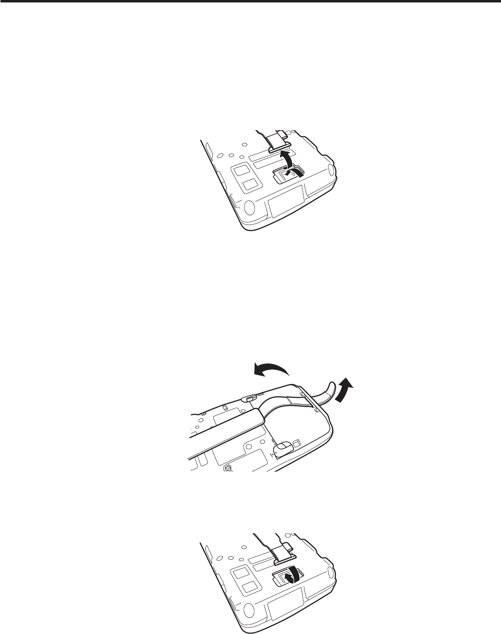
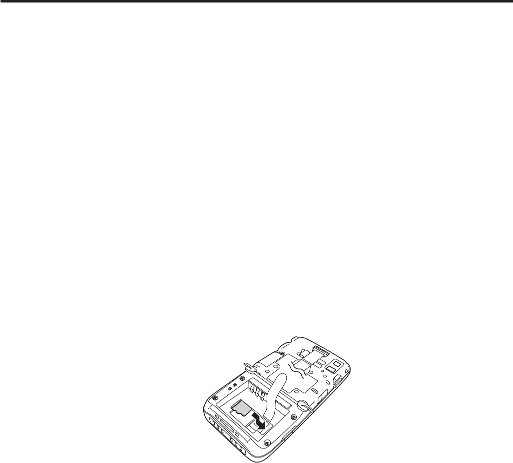
Installing
1. Make sure that the power on the terminal has been switched off. If the power is still
on, press the power key to switch off the power.
2. Remove the battery pack.
3. Put your ¿ nger’s nail into the slit of the plastic holder, and then lift it up. See the
¿ gure below.
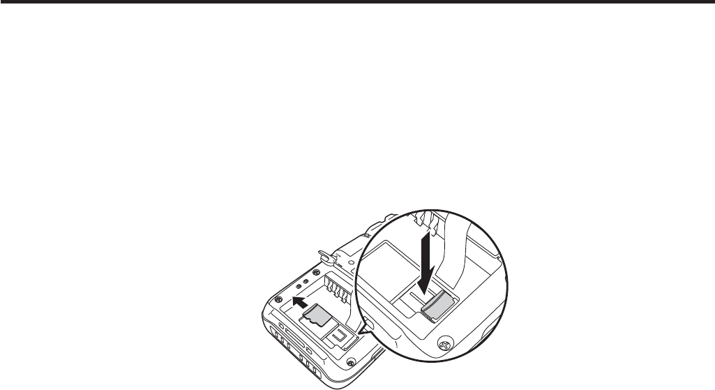
4. Load SIM card by sliding into the SIM card slot.
5. Make sure that the card has been inserted ¿ rmly and then put back the plastic holder
to its home position until you hear a click sound.
6. Load the battery pack.
E-28
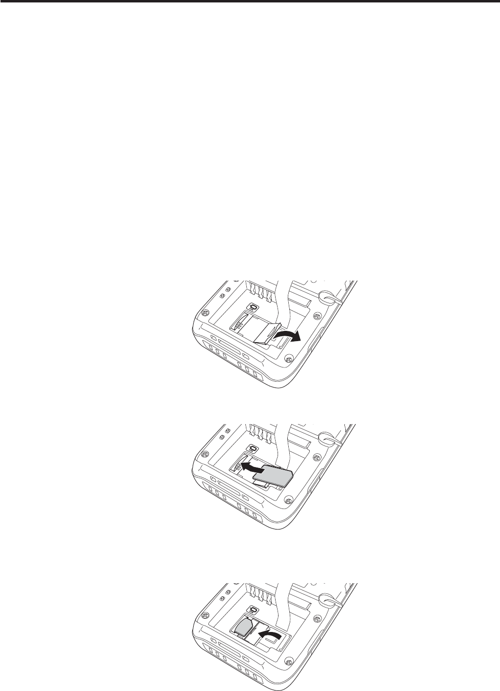
Removing
1. Make sure that the power on the terminal has been switched off. If the power is still
on, press the power key to switch off.
2. Remove the battery pack.
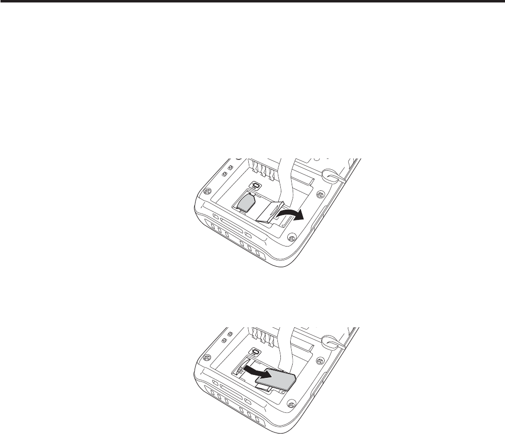
3. Put your ¿ nger’s nail into the slit of the plastic holder, and then lift it up. See the
¿ gure below.
4. Pull the SIM card out of the slot by sliding it to the direction shown by the arrow. See
the ¿ gure below.
5. Put back the plastic holder to its home position until you hear a click sound.
6. Load the battery pack.
Important!
A SIM card must be inserted with the top and bottom properly aligned and in
the proper direction. Attempt in inserting it with an excessive force in incorrect
orientation can risk damage to the connectors and slot.
The battery pack will not be able to be properly installed if the SIM card is not
properly installed. Reinstall the SIM card properly if this happens.
Since data recorded in the Handheld Terminal may be lost if the battery pack
is removed for more than 10 minutes, complete the installation (or removing) of
SIM card within 10 minutes.
x
x
x
E-29
Handling SD Memory Cards
SD memory card can be installed in the SD memory card slot on the Handheld
Terminal.
The employment of SD memory card slot is dependent on model. See page 13 for the
models with SD memory card slot integrated.
Install (or remove) an SD memory card according to the procedure described below.
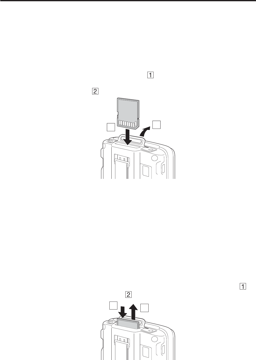
Installing
1. Open the cover of the SD memory card slot ( ) and insert an SD memory card all
the way in until the top of the SD memory card aligns with the entrance of the slot of
the Handheld Terminal ( ).
1
2
2. Close the cover of the SD memory card slot.
Important!
An SD memory card must be inserted with the top and bottom properly aligned
and in the proper direction. Attempt in inserting it with an excessive force in
incorrect orientation can risk damage to the connectors and slot.
Never turn off the power or remove an SD memory card from the slot while the
card is being accessed. Doing so can damage the SD memory card or data in the
card.
Do not drop the card or lose it.
Removing
1. Open the cover of the SD memory card slot and press on the SD memory card ( ).
The SD memory card is pushed out ( ).
12
2. Pull out the SD memory card and close the cover of the SD memory card slot.
x
x
x

E-30
Resetting the Handheld Terminal
Resetting the terminal is the same as resetting a PC. Performing a reset causes all
unsaved RAM data to be lost that are in mid-course of inputting and editing, but data
and settings that are already stored in the FlashROM should be unaffected.
Perform a reset to restore normal operation whenever the Handheld Terminal operates
abnormally due to misoperation or some other reason.
Use a stylus to press the reset switch on the back of the IT-800.
This starts the reset operation.
Do not use a toothpick or pencil or other sharp
object whose tip may break off the reset switch.
Performing a Full Reset (Initialization)
Performing a full reset deletes all data and resets various settings to their defaults.
*Data stored in the Flashdisk folder remain unaffected.
Perform a full reset whenever any one of the following conditions exists.
When you want to delete installed programs and settings, and resume the terminal to
the initial condition.
When you are no longer able to use the Handheld Terminal because you forgot your
password.
When the Handheld Terminal does not operate normally due to a memory problem.
Important!
Performing a full reset resets all data to their defaults except stored in the
Flashdisk folder. If possible, backup data of the terminal to a PC or to the
Flashdisk folder. The reset procedure and display message appeared on
performing the reset is according to the model you operate.
*
x
x
x
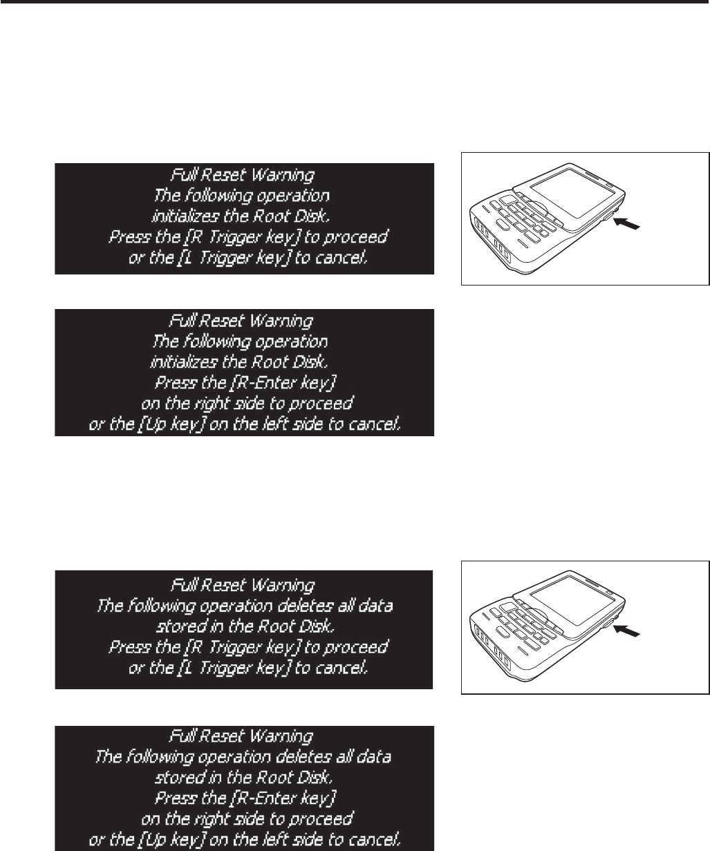
E-31
1. Hold down Fn key and CLR key while pushing down the reset switch for about 3
seconds with the tip of a stylus until the message shown below appears on the display.
To cancel the full reset operation, press L Trigger key on the scan engine integrated
models or Up key on the non-scan engine integrated models.
Message appeared on the scan engine integrated models.
R Trigger
key
Message appeared on the non-scan engine integrated models.
2. Press R Trigger key on the scan engine integrated models or R Enter key on the non-
scan engine integrated models. This causes the message shown below to appear.
To cancel the full reset operation, press L Trigger key on the scan engine integrated
models or Up key on the non-scan engine integrated models.
Message appeared on the scan engine integrated models.
R Trigger
key
Message appeared on the non-scan engine integrated models.
3. Press R Trigger key or R Enter key again to perform the full reset.
The full reset starts and all data in the memory are erased, and the start-up screen
appears.
Data stored in the Flashdisk folder remain unaffected.
x
x
x
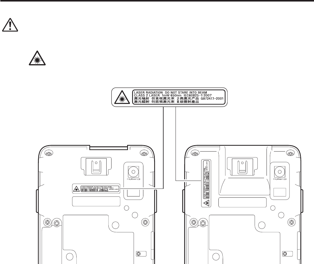
E-32
Warning Label
Warning!
■ Never look directly into the laser light.
These products scan using laser light. Never look directly into the laser light
or shine the laser light into the eyes.
IT-800R-15/RC-15/RGC-15/
RGC-35
IT-800R-35/A-35/RC-35/
EC-35
This label is a warning and caution label for Class 2 laser products that comply
with IEC60825-1:2007.
Although Class 2 laser light is only emitted momentarily, never look directly into
the beam light.
The laser light emitted by this laser scanner has a maximum output of less than
1 mW and a wavelength of 650 nm.
Use of controls or adjustments or performance of procedures other than those
speci¿ ed herein may result in hazardous radiation exposure.
x
x
x
x
x
IT-800A-35U
E-33
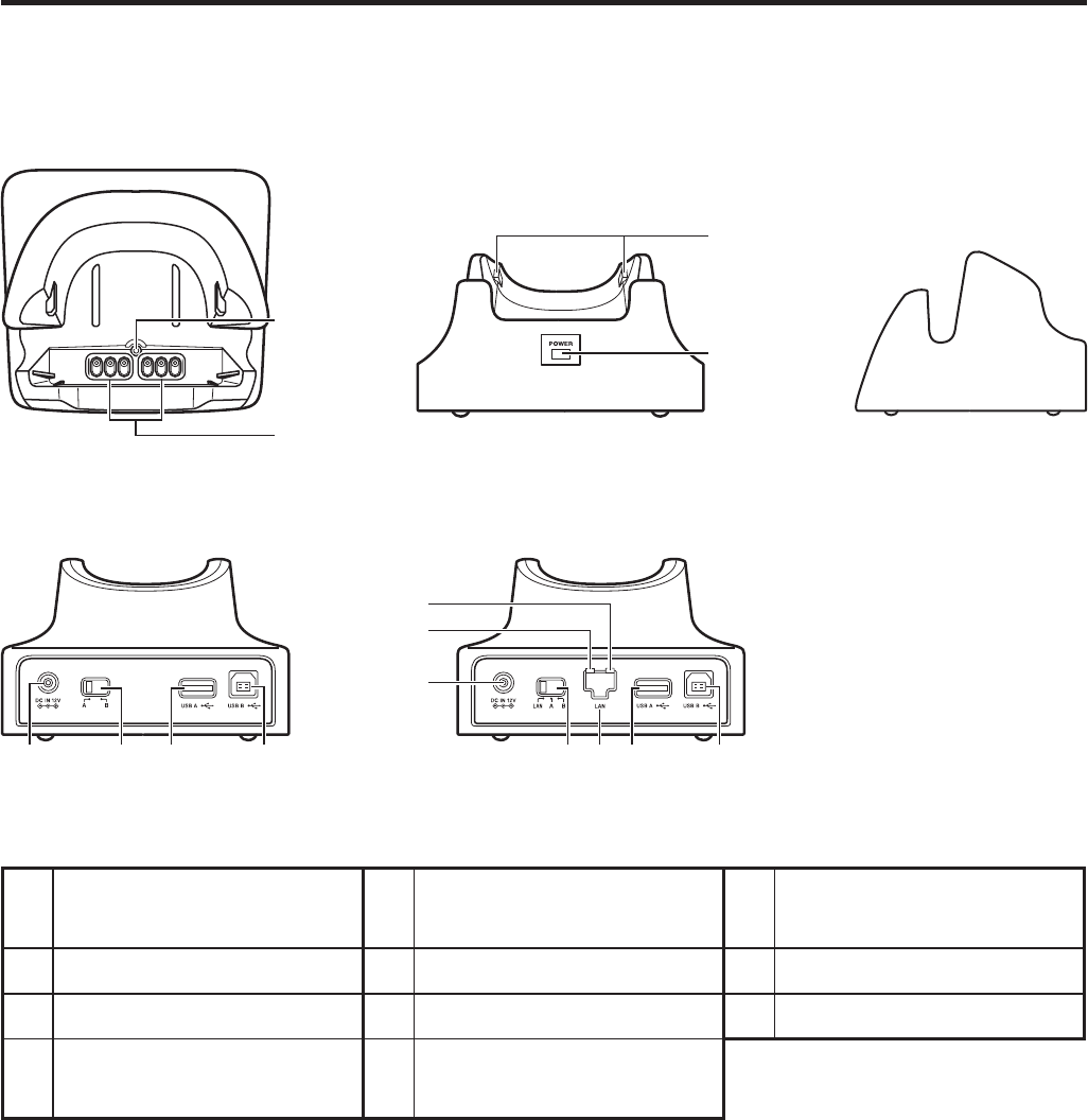
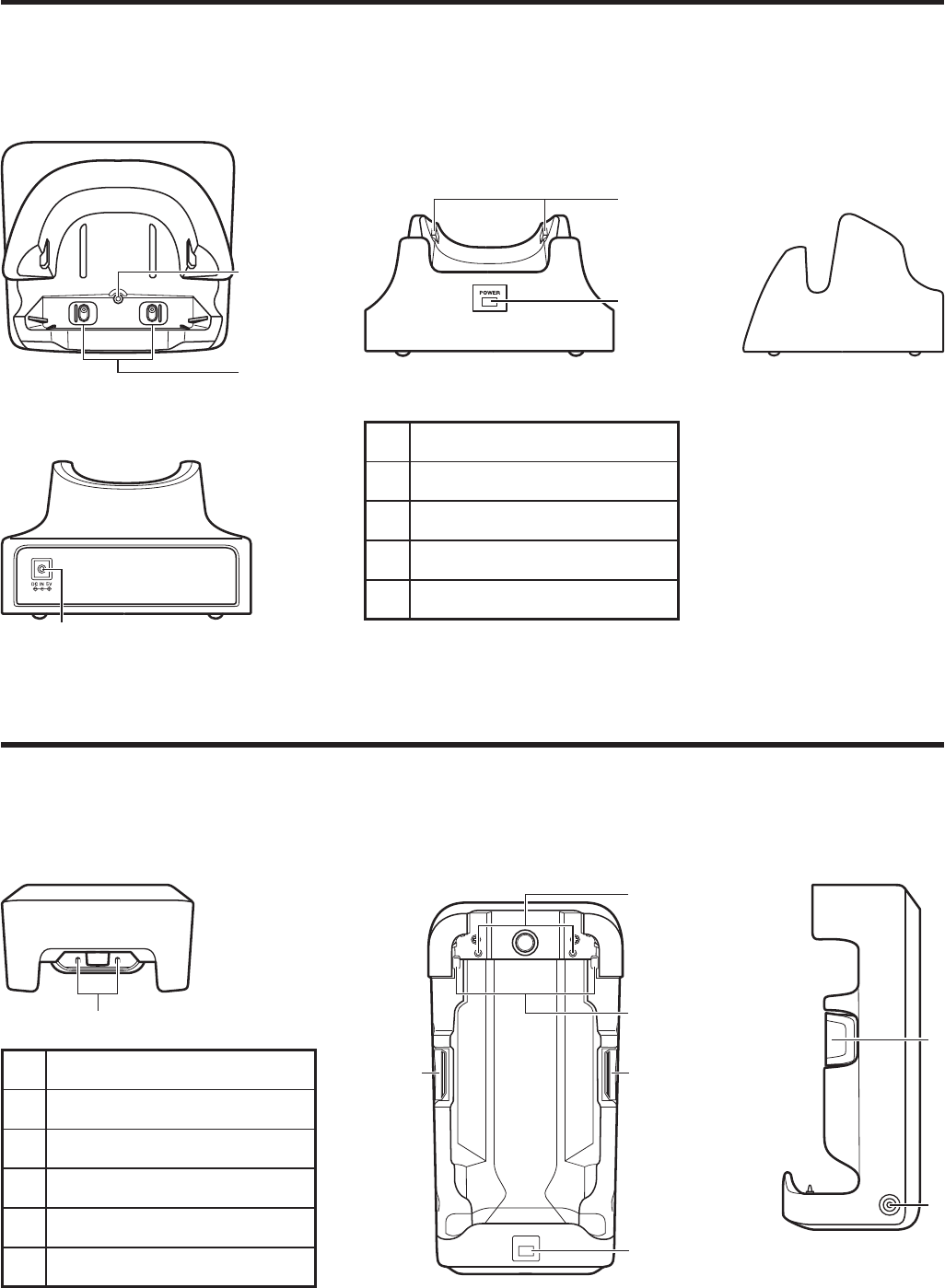
USB Cradle (HA-H60IO), Ethernet Cradle (HA-H62IO)
General Guide
Top
8
9
Front
11
10
Right
13
72
Back (HA-H60IO)
13
4
5
7
26
Back (HA-H62IO)
1 USB Client Port 5 LAN Communication
Status LED 9 Power/Signal Terminals
2 USB Host Port 6 LAN Port 10 Power Indicator LED
3 Selector Switch 7 AC Adaptor Jack 11 Mount Hooks
4LAN Connection Status
LED 8 Terminal Detect Switch
E-34
Car Mounted-type Battery Charger (HA-H35CHG)
General Guide
Cradle-type Battery Charger (HA-H30CHG)
General Guide
1
Back
Front
5
4
Top
2
3
1 AC Adaptor Jack
2 Terminal Detect Switch
3 Power Terminals
4 Power Indicator LED
5 Mount Hooks
Right
4
Top
3
6
2
5
2
Front
2
1
Right
1 Car Adaptor Jack
2 Removal Buttons
3 Terminal Detect Switch
4 Power Terminals
5 Power Indicator LED
6 Mount Hooks
Before the use of this charger for battery pack installed in WWAN models, see the
battery charge instruction on page E-17.
E-35
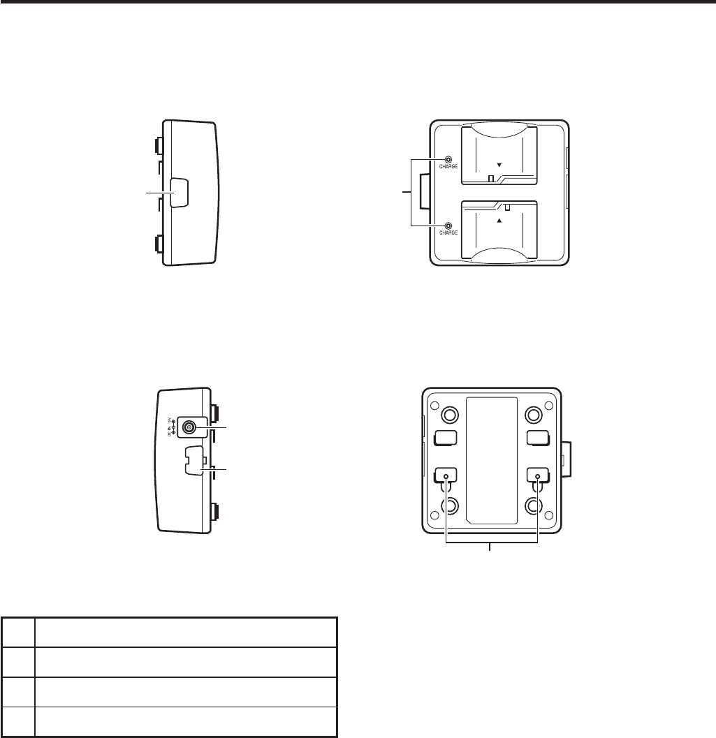
Dual Battery Charger (HA-D32DCHG)
General Guide
1 Charge Indicator LED
2 AC Adaptor Jack
3 Dual Battery Charger Connection Port
4 Connection Bracket Attachment Holes
Left
3
Top
1
Right
2
3
4
Bottom
E-36
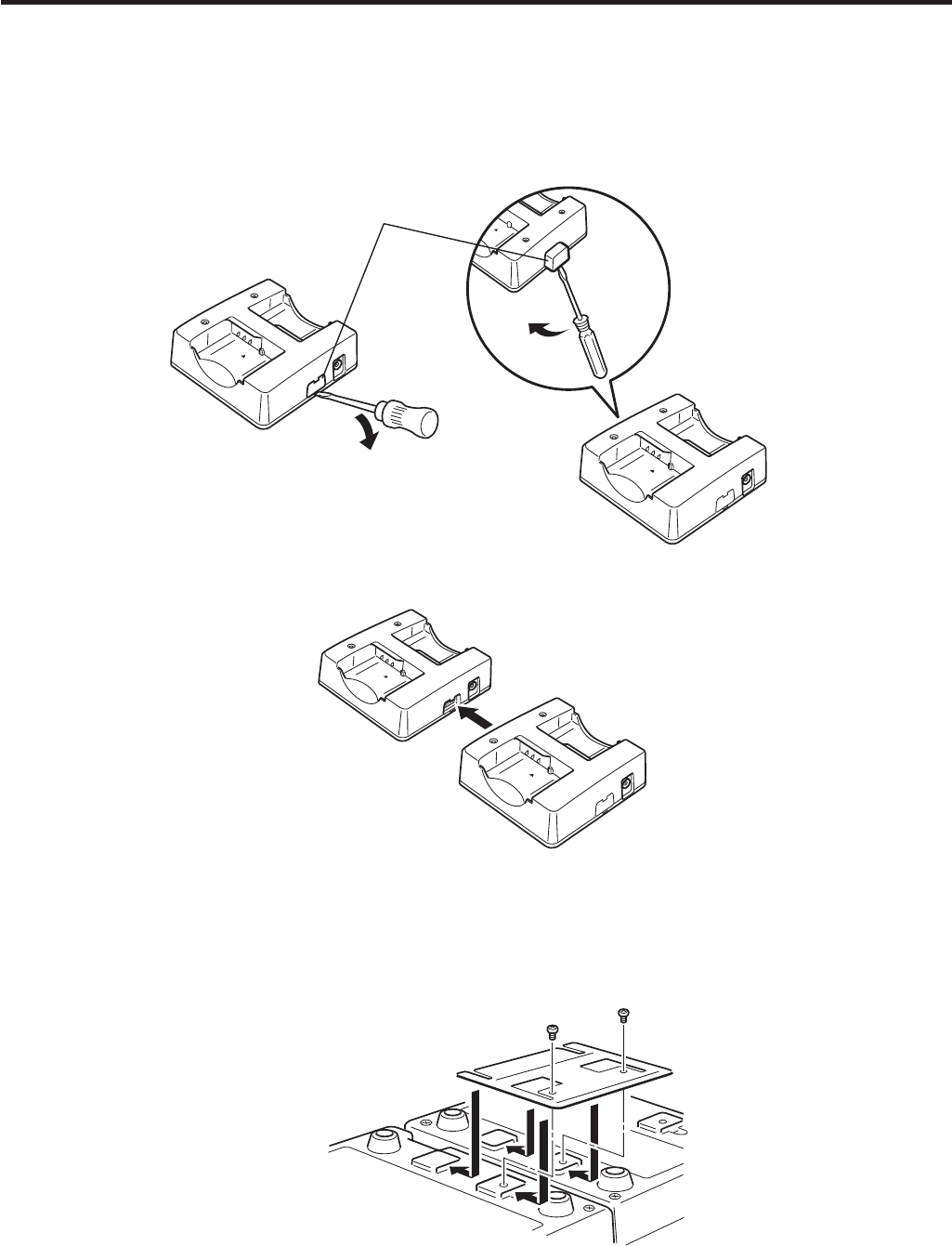
Connecting Multiple Dual Battery Chargers
1. As shown in the illustrations below, remove the connector covers of the Dual Battery
Chargers you want to connect to each other.
Connector cover
2. Connect the two Dual Battery Chargers as shown below.
3. Turn over the connected Dual Battery Chargers and attach a connection bracket,
securing it in place with screws.
You can repeat the above steps to connect up to 3 Dual Battery Chargers.

IT-800A-35U
CPU Marvell PXA320 624MHz
Memory 128MB RAM, 128MB Flash ROM (user defined: 80MB)
OS Microsoft Windows Mobile 6.1 operating system
Display 3.7-inch, 480 x 640-dots 2-Way TFT color LCD
Readable
symbologies
1D : UPC-A、UPC-E、EAN8 (JAN8)、EAN13 (JAN13)、
Codabar(NW-7)、Code39、Interleaved 2 of 5 (ITF)、MSI、
Code93、Code128 (GS1-128 (EAN128))、Code11、IATA、
GS1 DataBar Omnidirectional (RSS-14)、GS1 DataBar
Truncated (RSS-14 Truncated)、GS1 DataBar Limited
(RSS Limited) 、GS1 DataBar Expanded (RSS
Expanded)、Code32 Stacked 2D : PDF417、Micro PDF、
CODE49 、Composite 、Codablock F 、TLC39 、GS1
DataBar Expanded Stacked (RSS Expanded Stacked)、
GS1 DataBar Stacked (RSS-14 Stacked) Matrix 2D :
Aztec、DataMatrix、Maxicode、QR Code、MicroQR、
Chinese Sensible Code(Han Xin Code)
CMOS Imager
Scanning
distance
1D : Within approximately 45-410 mm
Stacked 2D : Within approximately 65-260 mm
Matrix 2D : Within approximately 55-195 mm
Interface IrDA Ver.1.3 LowPower
Synchronization Asynchronous,frame syanchronization
IR Port
Transmission
Rate
Up to 4Mbps(max)
Protocol Bluetooth Specification Ver2.0+EDR
Bluetooth
Range Approximately 3m
Standards Complies with IEEE 802.11a/b/g
Diffusion
Modulation
DSSS : 802.11b
DSSS/OFDM : 802.11a/11g
Wireless-LAN
Rang Indoor : 50m
Outdoor : 150m

Frequency
Band
13.56MHz
NFC
Supported
Cards
ISO14443TypeA、ISO14443TypeB、Felica
microSD Memory
Card Slot
Standards Compatible with SDHC Memory Card
Power Source Battery Pack
Power Supply
Memory
Backup
Rechargeable Lithium Battery(Built-in)
Temperature -20℃ to 50℃
Operating
Environment Humidity 10% to 90%RH(non-condensation)
Dimensions Approximately 78(W) x 159(D) x 25(H) mm
Dimensions Weight
Weight Approximately 275g

CASIO COMPUTER CO., LTD.
6-2, Hon-machi 1-chome
Shibuya-ku, Tokyo 151-8543, Japan
Printed on recycled paper.
PN410438-003
Printed in JapanMO1101-001001A
PN410438-003