Casio Computer IT9000C Handheld Printer Terminal User Manual IT 9000VA
Casio Computer Co Ltd Handheld Printer Terminal IT 9000VA
UserManual.wiki
>
Casio Computer
>
IT9000C User Manual
>
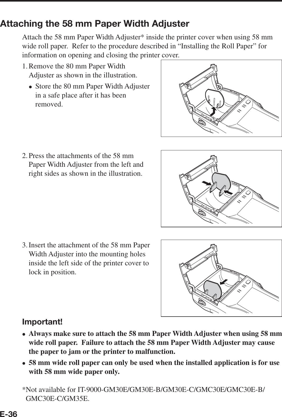
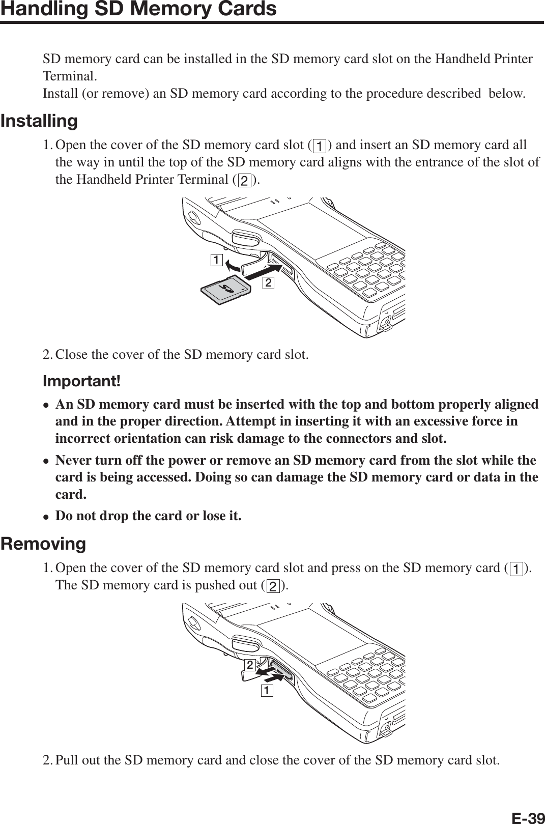
Users manual
Contents
1.
Users manual
2.
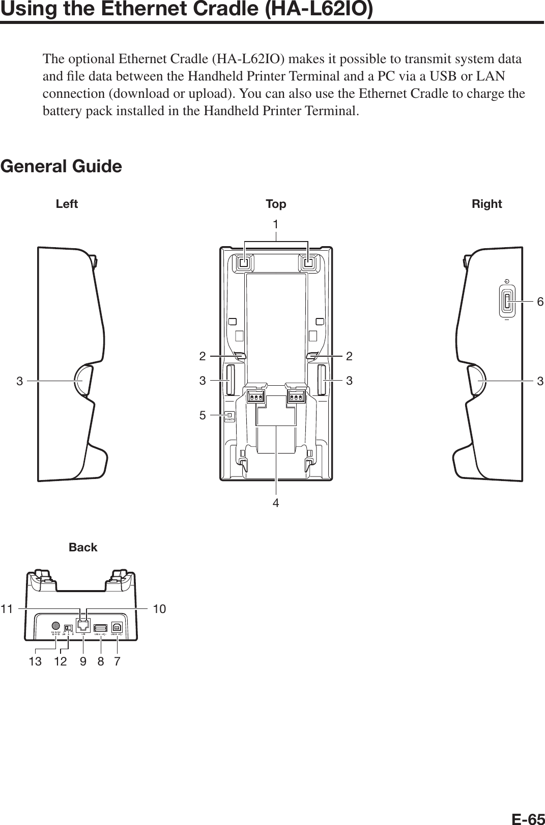
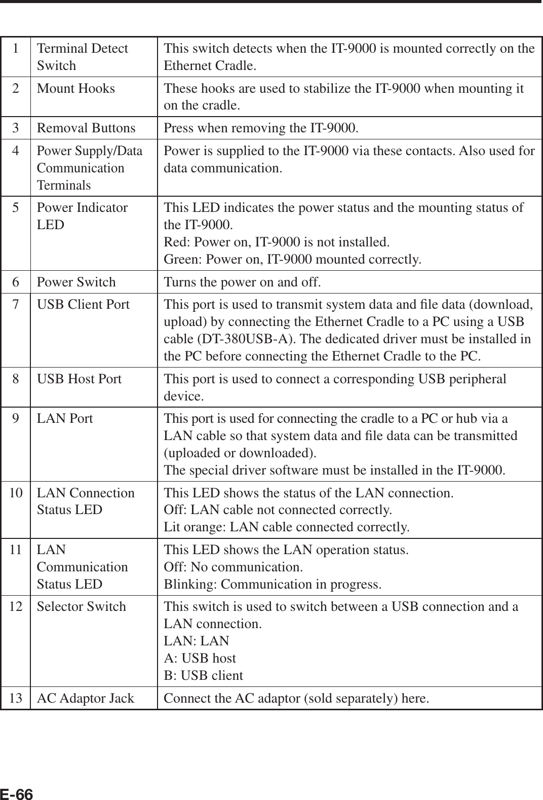
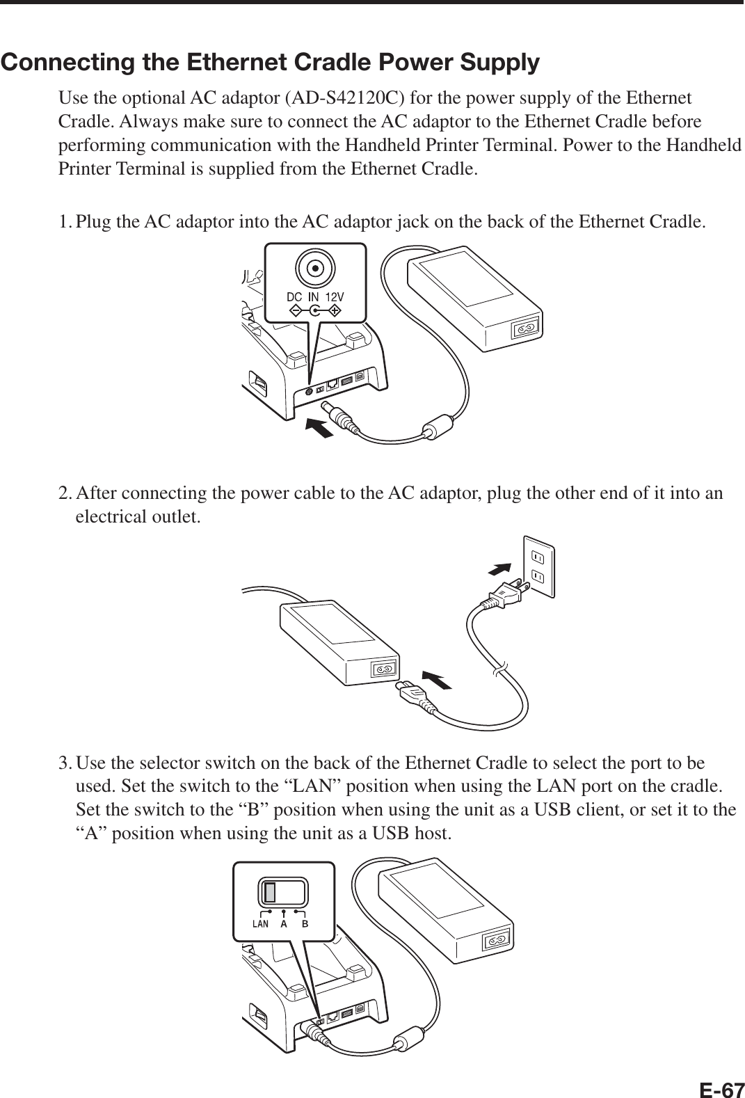
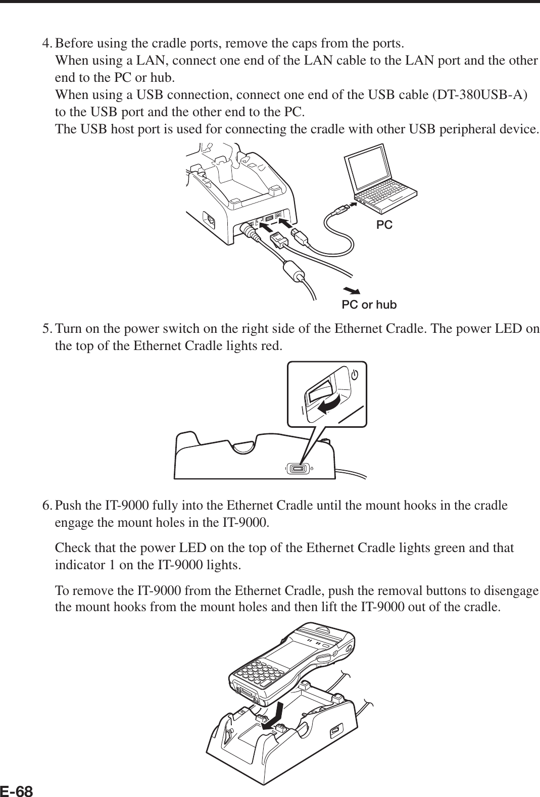
User manual
Users manual
Navigation menu
Upload a User Manual
Namespaces
Wiki Guide
HTML
PDF
Info
Views
User Manual
Discussion / Help
Navigation