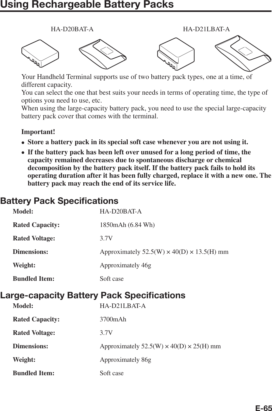
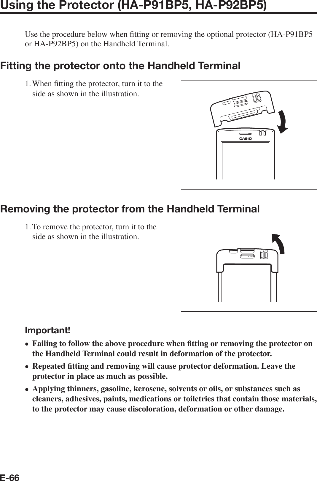
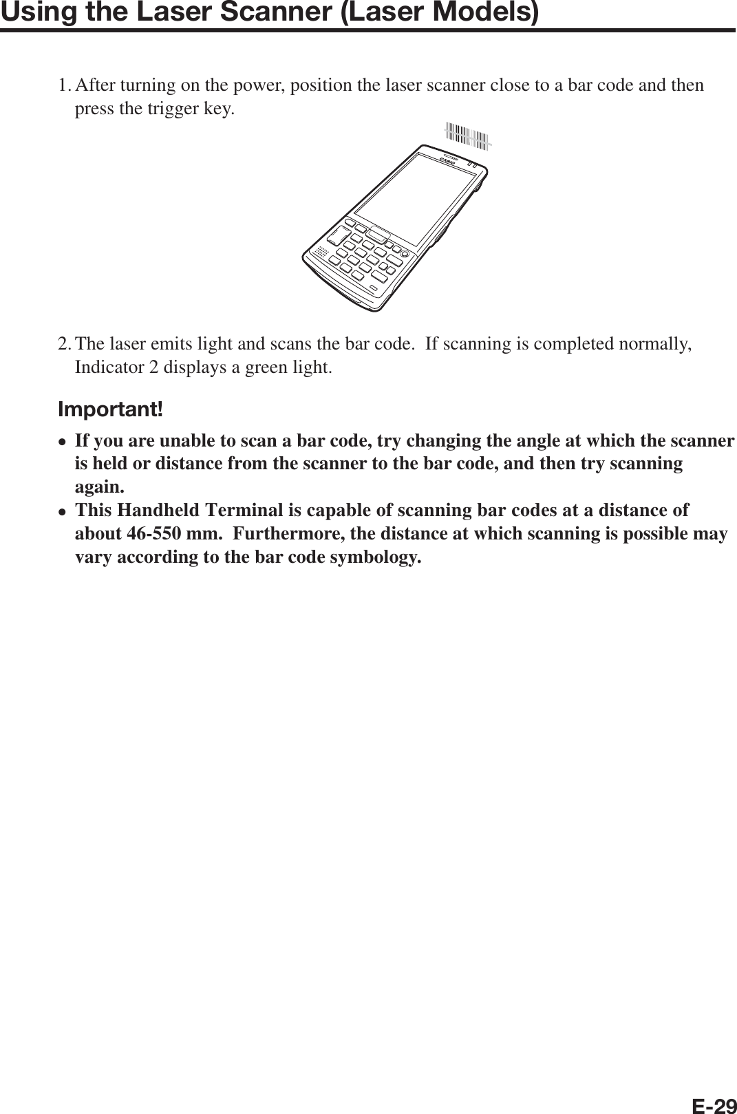
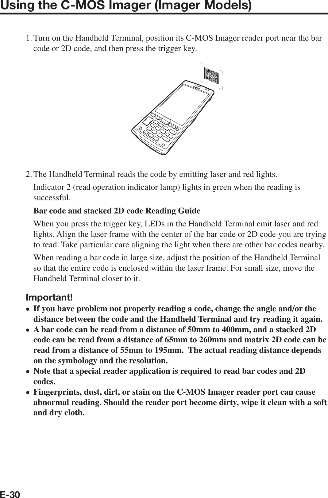
Casio Computer ITG500 Handheld Terminal User Manual IT G500
Casio Computer Co Ltd Handheld Terminal IT G500
UserManual.wiki
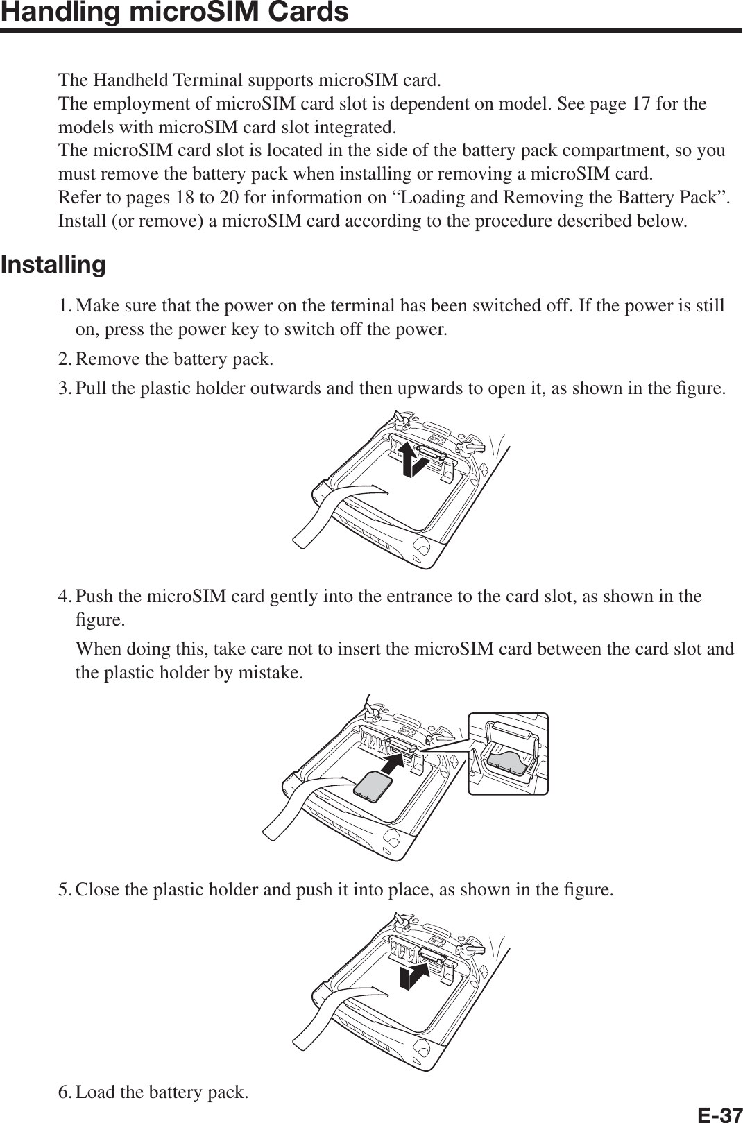
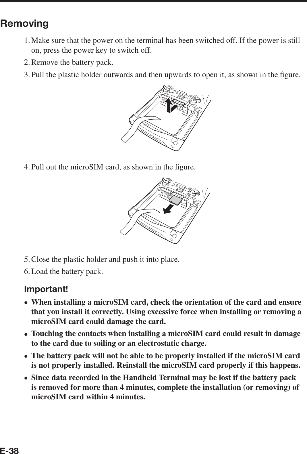
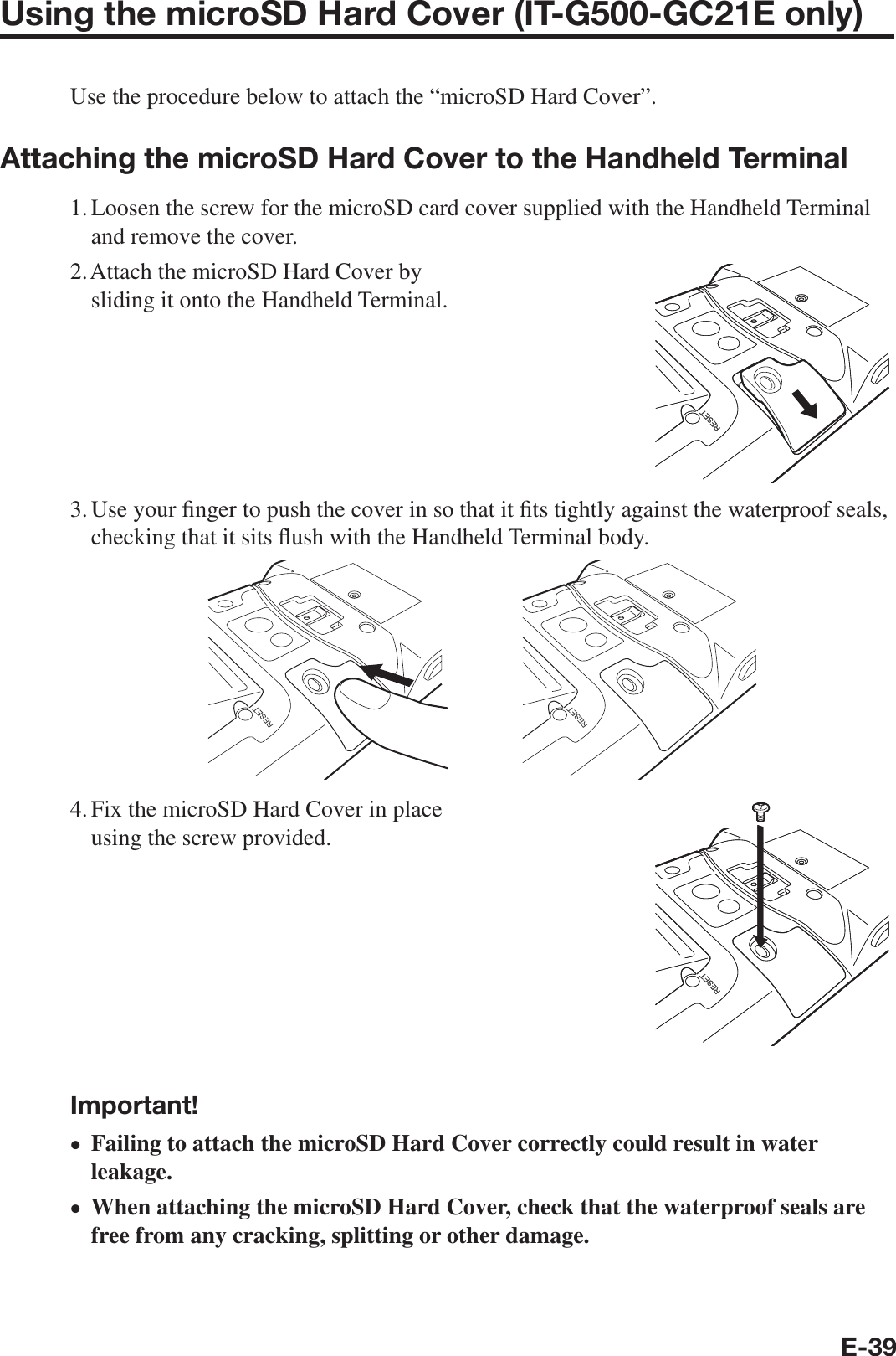
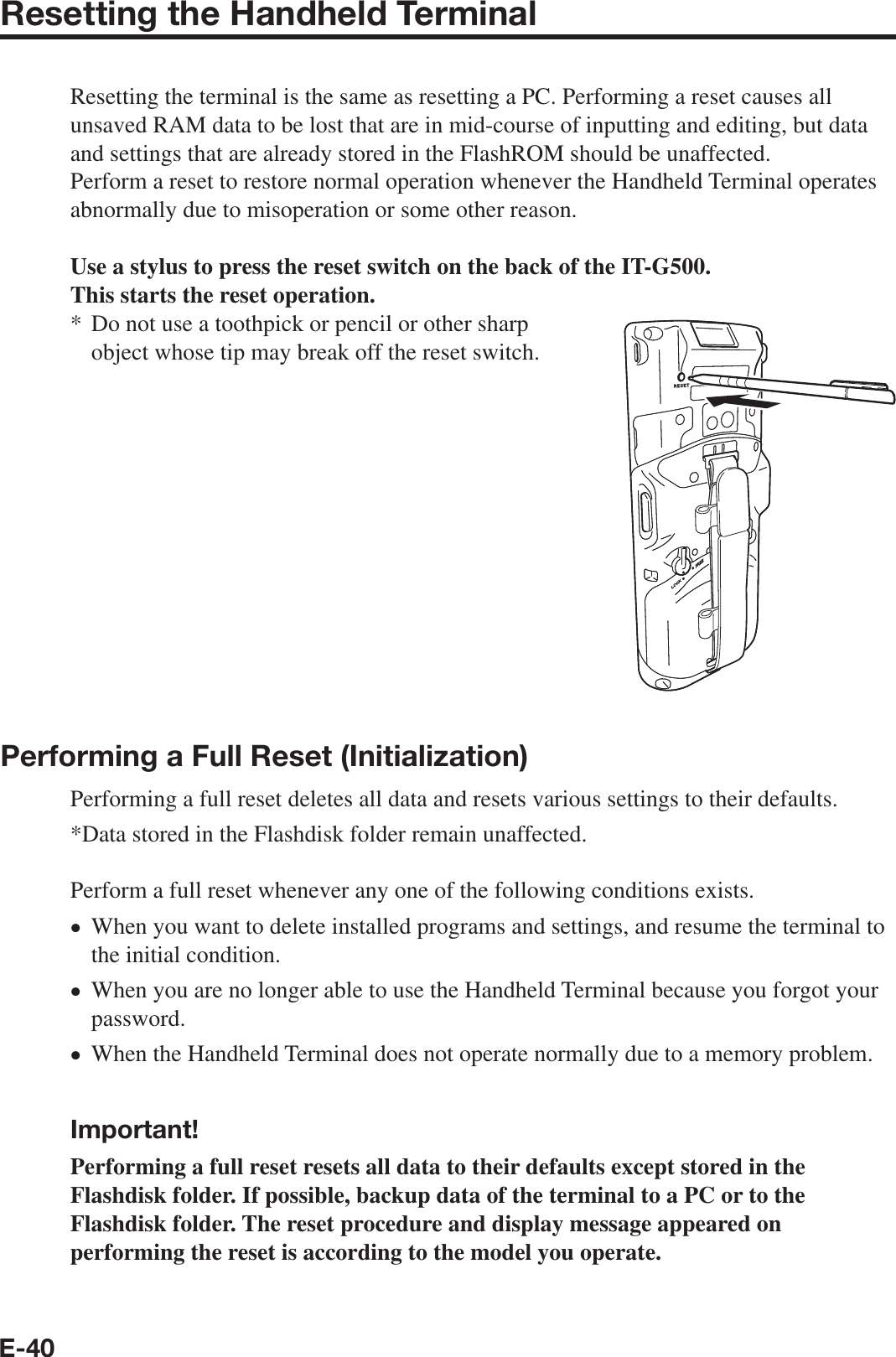
>
Casio Computer
>
ITG500 User Manual
User Manual
Navigation menu
Upload a User Manual
Namespaces
Wiki Guide
HTML
PDF
Info
Views
User Manual
Discussion / Help
Navigation
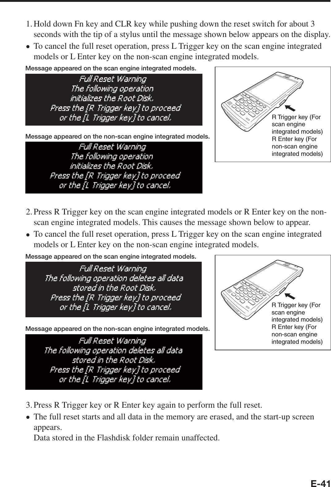
![E-31Adjusting the Laser Light Emission WidthThe emission width of the laser light emitted by the Handheld Terminal (model dependant) can be adjusted. Adjust the emission width when it is improper.1. Navigate to the menus in the following sequence: Start Settings System The Control Panel appears as shown in the screen.2. Tap the [Scanner Setting] icon. The Setting screen appears as shown in the screen.3. Tap the [Others] tab in the Scanner Setting screen.](https://usermanual.wiki/Casio-Computer/ITG500/User-Guide-3044470-Page-33.png)
![E-324. Tap the [Calibration] button. The display appears as shown at right.5. Press the trigger key to emit laser light, and align the light with the barcode for adjusting emission width.Align the laser light with the narrow bars on both sides.The message appears as shown at right when adjustment is completed.Repeat the setting if “Setting failed” message appears.Emission Width Adjustment Bar code•••](https://usermanual.wiki/Casio-Computer/ITG500/User-Guide-3044470-Page-34.png)