Casio Computer VR7100 Electronic Cash Register User Manual
Casio Computer Co Ltd Electronic Cash Register
Contents
- 1. Manual
- 2. Users Manual
- 3. User Manual
- 4. User manual
User manual
DeutschFrançaisEspañolEnglish
User’s Manual
Manual del usuario
Manuel de l’utilisateur
Bedienungsanleitung
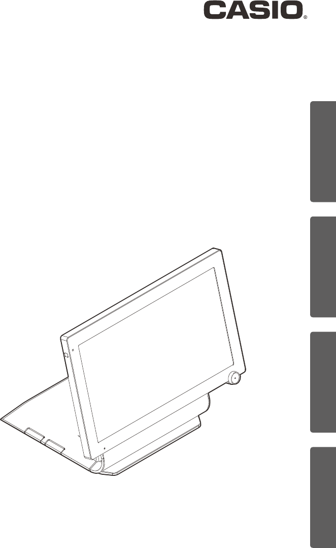
Touch Screen Terminal
Terminal de pantalla táctil
Borne de l’écran tactile
Touchscreen-Terminal
V-R7100
V-R7100-C

E-1
Thank you very much for purchasing the V-R7100-C/R7100. Please read this User’s Manual
thoroughly and use the product accordingly. Please pay particular attention to the “Safety
Precautions”. Please keep the User’s Manual in a safe and convenient place for future
reference after reading.
Contents
Safety Precautions ...................................................E-2
Precautions for Use...................................................E-8
Conrming the Accessories............................................E-10
Basic Operation ..............................................E-11
Name of Parts and What They Do ......................................E-12
Power ON/OFF .....................................................E-15
Daily Use ........................................................E-15
Moving and Cleaning...............................................E-16
Description of the Indicator ............................................E-17
Adjusting the Angle of the Display.......................................E-18
When the Drawer Does not Open
(if using the optional CASIO drawer).....................................E-18
Installation...................................................E-19
Name of Parts and What They Do ......................................E-20
Connecting the Power Supply and Various Devices .........................E-22
Connecting the Drawer cable ........................................E-22
Connecting the AC Adaptor ..........................................E-23
Connecting Other Devices...........................................E-23
Preparing the Stand................................................E-25
Setting the Stand and the Display .....................................E-26
Installation features . . . . . . . . . . . . . . . . . . . . . . . . . . . . . . . . . . . . . . . . . . . . . . . . E-28
MCR Unit (VA-B46MCRE) Installation..................................E-29
Specication .......................................................E-30
E-2
Safety Precautions
●Please read this “Safety Precautions” thoroughly and use the product accordingly.
●Please pay due attention to the following symbols to help you use the product safely and proper-
ly and to avoid any personal injury or damage to the product.
*Warning This symbol indicates the contents that may cause death or serious injury to a
person when the product is misused ignoring this symbol.
*Caution This symbol indicates the contents that may cause injury to a person or property
damage when the product is misused ignoring this symbol.
●The “pictorial indications” in this manual have the following meanings.
’This symbol means “to be careful = caution”. The example at left is “caution for
electrical shock”.
!This symbol means “must not do = prohibited”. The example at left is “prohibited to
disassemble”.
$This symbol means “something must be done = instruction”. The example at left is
“disconnect the power plug from the outlet”. The “instructions difcult to express in
picture” are indicated by +.
*Warning
Using the AC power supply
-
’
●Do not twist, pull, heat, modify, or place anything heavy on the power cord. This may
damage the power cord and result in re or electrical shock.
● Contact the dealer or the CASIO service representative when the power cord is dam-
aged (wire is exposed or disconnected). Using the power cord in such condition may
result in re or electrical shock.
●Securely insert the power plug all the way.
●Do not touch the power plug with wet hands. This may result in electrical shock.
● Do not use any AC adaptor or the power cord other than the parts included in the
product. Also, do not use the AC adaptor or the power cord included in the product with
other product. This may result in re or electrical shock.
Power supply voltage
- ●Do not use with any voltage other than the indicated power supply voltage. This may
result in re or electrical shock.
● Do not overload the outlet with wires. This may result in re or electrical shock.
Do not disassemble or modify
! ●Do not disassemble or modify the product. There are high voltage parts and sharp
parts inside. Touching them may result in injury or electric shock, or cause a malfunc-
tion or re.

E-3
*Warning
Do not let any foreign object or water get inside
-
$
● Do not insert or drop metal object or ammable object inside from the opening.
● Do not spill any liquid such as water from a ower vase, coffee, juice, etc., inside this
product.
●Disconnect the power plug from the outlet and contact the dealer where the product
was purchased or the CASIO service representative when a foreign object or water
got inside the product. Using the power cord in such condition may result in re or
electrical shock.
Do not use the product in abnormal condition
- ● It may result in re or electrical shock when the product is used in abnormal condition
such as overheating, it is smoking, have strange odor, etc. Immediately disconnect the
power plug from the outlet and contact the dealer where the product was purchased or
the CASIO service representative.
*Caution
Installation location
- ●Do not place in unstable locations such as on an unsteady table or an inclined location.
It could fall and cause injure.
● Do not place in a location with high humidity or dust. This may result in re or electrical
shock.
●Do not place in a location exposed to oil smoke or humidity such as close to cooking
table or humidier. This may result in re or electrical shock.
●Do not place in a location close to heating devices such as a stove or a heater, or
location directly exposed to hot air. This may result in re.
●Select the outlet where the power cord of this product is easily reached, and plug/
unplug of the power plug can easily be performed.
Do not place anything on top
- ● Do not place ower vase or ower pot, cup or container with liquid, or metal object.
●Do not place anything that is hot such as cigarette.
●Do not place anything heavy.
●Do not place your hands and lean on the product.
When moving the product
$ ● Always disconnect the power plug from the outlet before moving.
● Always hold onto the plug when unplugging the power plug.
● Pulling on the power cord may damage the cord, resulting to re or electrical shock.

E-4
*Caution
LCD
- ●Do not press hard on the LCD or apply strong impact. This may crack the glass on the
LCD, resulting to injury.
●Never touch the liquid from inside when the LCD is cracked. This may result in irritation
to the skin.
●Immediately rinse the mouth and contact the physician when the liquid inside the LCD
gets inside the mouth.
●Rinse for minimum of 15 minutes with clean running water and contact the physician
when the liquid inside the LCD gets in the eye or on the skin.
Handling of screen and key
- ● Do not press the touch screen or keys at side with a sharp object or hard object such
as ballpoint pen. This may result in malfunction.
● Press with nger instead of pressing hard with nger nail when operating.
Adjustment of display
- ● Take care not to pinch nger with the tilt knob and its surrounding when adjusting the
angle of the display. This may result in injury.
Drawer (If using the optional CASIO drawer)
+
-
●Take caution with the face of a child or pregnant person when opening a drawer.
● Do not lean on the drawer when the drawer is opened. It could fall and cause injure.
Cleaning
$
+
●Unplug the power plug from the outlet for safety when cleaning.
●Clean the blades and surrounding of the blades of the power plug with a dry cloth at
least once a year. Dust accumulation may result in re. Do not use detergent to clean
the power plug.
When not using for a long period
$ ●Unplug the power plug from the outlet for safety when not using this product for a long
period such as consecutive holidays.
Handling of Wireless Communication Function
*Warning
Interference with the Operation of Other Equipment
(Using Wireless Data Communication)
+ ●In hospitals and other facilities where medical equipment is present, follow the
instructions provided by the facility. In particular, turn OFF the power or the wireless
communication function in operating theaters, intensive care units, coronary care units
or any area where use of such products is prohibited by the facility.

E-5
Regulatory Information
The USA and Canada
For Users in Canada
These Class A digital apparatuses comply with Canadian ICES-003.
Cet appareil numérique de la classe A est conforme à la norme NMB-003 du Canada.
This device complies with Industry Canada licence-exempt RSS standard(s). Operation is subject
to the following two conditions: (1) this device may not cause interference, and (2) this device must
accept any interference, including interference that may cause undesired operation of the device.
Le présent appareil est conforme aux CNR d’Industrie Canada applicables aux appareils radio
exempts de licence. L’exploitation est autorisée aux deux conditions suivantes : (1) l’appareil ne doit
pas produire de brouillage, et (2) l’utilisateur de l’appareil doit accepter tout brouillage radioélec-
trique subi, même si le brouillage est susceptible d’en compromettre le fonctionnement.
Caution Exposure to radio frequency radiation
To comply with FCC/IC RF exposure compliance requirements, this device must not be co-located
or operating in conjunction with any other antenna or transmitter except in accordance with the FCC/
IC multi-transmitter product procedures or as described in the ling.
Précaution Exposition aux champs de radiofréquences
Pour respecter les normes relatives aux radiofréquences FCC/IC, ce dispositif ne doit pas être situé
ou utilisé à proximité d’une autre antenne ou d’un autre émetteur si ce n’est selon les procédures
mentionnées pour le multi-transmetteur FCC/IC ou décrites dans la documentation.
Caution Exposure to radio frequency radiation
To comply with FCC RF exposure compliance requirements, this device must not be co-located or
operating in conjunction with any other antenna or transmitter except in accordance with the FCC
multi-transmitter product procedures or as described in the ling.
FCC WARNING:
Changes or modifications not expressly approved by
the party responsible for compliance could void the user’s authority to operate
the equipment.
WARNING: This equipment has been tested and found to comply with the limits for
a Class A digital device, pursuant to Part 15 of the FCC Rules. These limits are designed
to provide reasonable protection against harmful interference when the equipment is
operated in a commercial environment. This equipment generates, uses, and can radiate
radio frequency energy and, if not installed and used in accordance with the instruction
manual, may cause harmful interference to radio communications. Operation of this
equipment in a residential area is likely to cause harmful interference in which case
the user will be required to correct the interference at his own expense.
GUIDELINES LAID DOWN BY FCC RULES FOR USE OF THE UNIT IN THE U.S.A.
(Not applicable to other areas)
This device complies with part 15 of the FCC Rules. Operation
is subject to the following two conditions: (1) This device
may not cause harmful interference, and (2) this device must
accept any interference received, including interference that
may cause undesired operation.

E-6
WARNING
THIS IS A CLASS A PRODUCT. IN A DOMESTIC ENVIRONMENT THIS PRODUCT MAY CAUSE
RADIO INTERFERENCE IN WHICH CASE THE USER MAY BE REQUIRED TO TAKE ADEQUATE
MEASURES.
Caution:
Users should also be advised that
(i) the device for operation in the band 5150-5250 MHz is only for indoor use to reduce the potential
for harmful interference to co-channel mobile satellite systems;
(ii) the maximum antenna gain permitted for devices in the bands 5250-5350 MHz and 5470-5725
MHz shall comply with the e.i.r.p. limit; and
(iii) the maximum antenna gain permitted for devices in the band 5725-5825 MHz shall comply with
the e.i.r.p. limits specied for point-to-point and non point-to-point operation as appropriate.
High-power radars are allocated as primary users (i.e. priority users) of the bands 5250-5350 MHz
and 5650-5850 MHz and that these radars could cause interference and/or damage to LE-LAN
devices.
Les utilisateurs devraient aussi être avisés que
(i) les dispositifs fonctionnant dans la bande 5 150-5 250 MHz sont réservés uniquement pour une
utilisation à l’intérieur an de réduire les risques de brouillage préjudiciable aux systèmes de
satellites mobiles utilisant les mêmes canaux;
(ii) le gain maximal d’antenne permis pour les dispositifs utilisant les bandes 5 250-5 350 MHz et 5
470-5 725 MHz doit se conformer à la limite de p.i.r.e.;
(iii) le gain maximal d’antenne permis (pour les dispositifs utilisant la bande 5 725-5 825 MHz) doit
se conformer à la limite de p.i.r.e. spéciée pour l’exploitation point à point et non point à point,
selon le cas.
De plus, les utilisateurs de radars de haute puissance sont désignés utilisateurs principaux (c.-à-d.,
qu’ils ont la priorité) pour les bandes 5 250-5 350 MHz et 5 650-5 850 MHz et que ces radars
pourraient causer du brouillage et/ou des dommages aux dispositifs LAN-EL.
Under Industry Canada regulations, this radio transmitter may only operate using an antenna of
a type and maximum (or lesser) gain approved for the transmitter by Industry Canada. To reduce
potential radio interference to other users, the antenna type and its gain should be so chosen that
the equivalent isotropically radiated power (e.i.r.p.) is not more than that necessary for successful
communication.
Conformément à la réglementation d'Industrie Canada, le présent émetteur radio peut fonctionner
avec une antenne d'un type et d'un gain maximal (ou inférieur) approuvé pour l'émetteur par
Industrie Canada. Dans le but de réduire les risques de brouillage radioélectrique à l'intention des
autres utilisateurs, il faut choisir le type d'antenne et son gain de sorte que la puissance isotrope
rayonnée équivalente (p.i.r.e.) ne dépasse pas l'intensité nécessaire à l'établissement d'une
communication satisfaisante.
E-7
Europe
Manufacturer:CASIO COMPUTER CO., LTD.
6-2, Hon-machi 1-chome, Shibuya-ku, Tokyo 151-8543, Japan
Responsible within the European Union:CASIO EUROPE GmbH
CASIO-Platz 1, 22848 Norderstedt, Germany
Please keep all information for future reference.
The declaration of conformity may be consulted at http://world.casio.com/
V-R7100
Products are for distribution within all member states of the EU.
0984
Laite on liitettävä suojamaadoituskostkettimilla vaurstettuun pistorasiaan
Apparatet må tilkoples jordet stikkontakt
Apparaten skall anslutas till jordat nätuttag.
The main plug on this equipment must be used to disconnect mains power.
Please ensure that the socket outlet is installed near the equipment and shall be easily accessible.

E-8
Precautions for Use
Read the following items thoroughly and use this product properly. CASIO bears no responsibility
whatsoever for malfunction or damage caused by handling not following below contents. Please
note that it will also result in charged repair, and actual cost required for repair will be charged,
even if it is within the warranty period.
Installation Location
Do not place in a hot or dusty location, or in any location exposed to oily smoke or water. Never
store or leave in following locations. This could erase the memory and cause a malfunction or
result in deformation of the case.
●Temperature of 0°C or lower
●Close to air conditioner
●Under direct sunlight
● Temperature of 40°C or higher
Avoid using this product in following locations.
●Outdoor
●Close to equipment that will become hot such as range, electrical heater, etc.
●Location exposed to water or steam
●Location with severe change in environment such as temperature, humidity, etc.
●Location where corrosive gas or saline matter is generated
●Location where dirt or dust is generated
●Location with vibration
●Location prone to static electricity
Dead Pixels
The LCD panel employed in this product uses high precision and substantial number of compo-
nents which commonly cause a small number of the pixels not to light or to remain lit all the time.
This is due to the characteristics of LCD panel yield in accuracy over 99.99% and permissible.
802.11a/n Restrictions
● This product is for indoor use only when using channels 36, 40, 44, 48, 52, 56, 60, or 64 (5150-
5250 MHz).
●To ensure compliance with local regulations, be sure to select the country in which the access
point is installed.
Other
●Do not turn off the power or remove the SD card while writing to or reading from the SD card.
This may result in damage to the SD card or stored data.
● Prepare separate AC power supply from the power line for motor, ice maker, microwave oven,
etc., which may generate noise.
●Do not touch the power switch with wet hands. This may result in electrical shock.
●Wipe thoroughly with dry cloth, etc., when there is any water droplet on the device.
● Do not use any volatile chemical such as thinner, benzine, cosmetics, etc., for cleaning. Wipe
with dry soft cloth when this product gets dirty. The display section may be scratched when
scuffed strongly with a cloth.
●The cover or the plastic case for the terminal may discolor or damaged when thinner, gasoline,
kerosene, various solvent, grease, any cleaner including them, adhesive, paint, medical agent,
cosmetics, etc., are adhered. Please be cautious.
V-R7100-C
E-9
Take Advance Notice of the Following
● The content of this manual may be changed without prior notice due to improvement or speci-
cation change of the product.
● Please note that CASIO bears no responsibility for damage, loss of prot, or any claim from third
party due to loss or change of data caused by usage, malfunction, or repair of this product.
●The copyright for this manual and all rights related to the software described in this manual
are the property of CASIO Computer Co., Ltd. The unauthorized reproduction of this manual in
whole or part is prohibited without the written permission of CASIO.
●The content of this manual was created with all possible care, but please contact us if there is
any unclear point, mistake, omission, etc., in this manual.
●The screen or illustration used in this manual may be different from the actual product. The keys
and icons are described in simplied manner.
●Weld Line
The line on the exterior of the product is called “weld line”, which is created at the time of plastic
forming, and it is not a crack or a scratch. This will not interrupt the usage.
Trademark Registration
SD, SDHC, microSD and microSDHC are trademarks of SD-3C, LLC.
HDMI (High-Denition Multimedia Interface) and the HDMI logo are
trademarks of HDMI Licensing, LLC.
Android logo are trademarks or registered trademarks of Google, Inc.
BLUETOOTH is a registered trademark owned by Bluetooth SIG, Inc.
and licensed to CASIO Computer Co., Ltd.
E-10
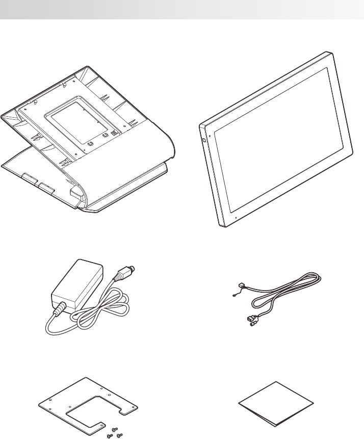
Conrming the Accessories
Stand Display
AC adaptor Drawer cable
Connector cover Dust cover
● Power cord (US only)
●User’s Manual (this manual)
● Warranty (US only)

Basic Operation
E-11
Basic Operation
This chapter describes about the basic operation method of this product after the installa-
tion.
Name of Parts and What They Do .....................................E-12
Power ON/OFF.....................................................E-15
Daily Use ........................................................E-15
Moving and Cleaning...............................................E-16
Description of the Indicator ..........................................E-17
Adjusting the Angle of the Display ....................................E-18
When the Drawer Does not Open (if using the optional CASIO drawer) ......E-18
E-12
Name of Parts and What They Do
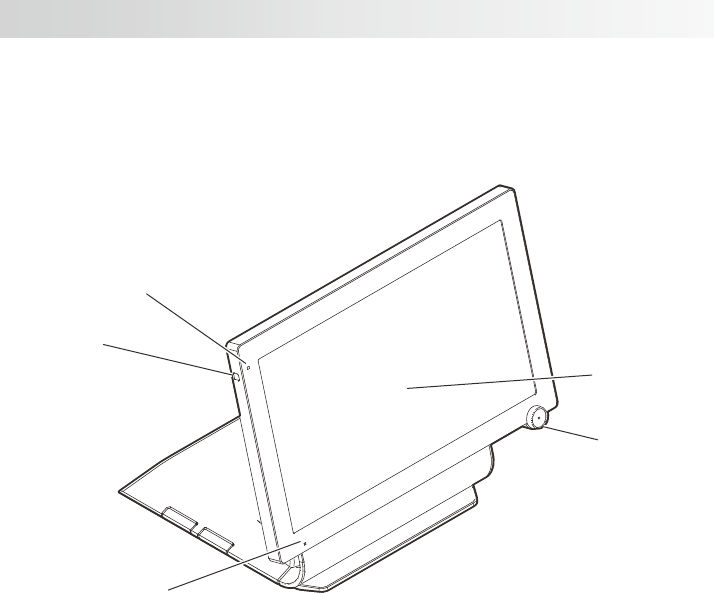
* The operation of the various parts is described with reference to the illustration of the
display mounted on the stand.
<Front>
2
1
3
4
5
1 Indicator Display the status of the power supply.
2 Power switch Turn the power ON. It will display the shutdown menu when
pressed and held. Switch the ON and OFF of the screen
display.
3 Microphone Input the audio.
4Touch screen panel Display each menu. Used for data input.
5 Dallas key For operators to sign on and off. (Factory option)
Name of Parts and What They Do
Basic Operation
E-13
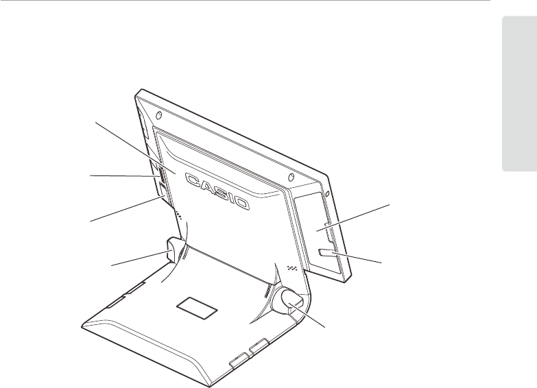
<Rear>
8
7
9
11
6
9
10
6 Rear cover Open when connecting the power supply or various devices.
7 Speaker Output the audio.
8 Main power switch cover Cover for the main power switch.
9 Tilt knob Adjust the angle of the display.
10 Earphone jack cover Cover for the earphone jack.
11 Side cover Cover for various switches and slots at the left side.
E-14
Name of Parts and What They Do
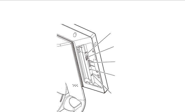
<Left side (when the side cover is opened)>
12
13
14
15
16
12 OFF switch Turn the power OFF.
13 USB (host) port (for maintenance) A port for maintenance. Do not use.
14 SD/SDHC memory card slot (for maintenance) A slot for maintenance. Do not use.
15 Reset switch (for maintenance) A switch for maintenance. Do not use.
16 Earphone jack Connect the earphone.
Basic Operation
E-15
Power ON/OFF
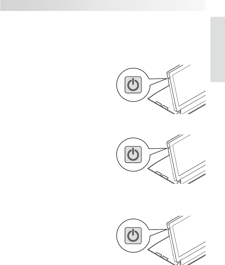
This product has 3 power switches, the main power switch, power switch, and the OFF
switch.
Daily Use
Turning the Power ON
1. Press the power switch.
The screen will turn on.
Turning to sleep mode
1. Press the power switch while the power
is ON.
The screen will turn off.
• The screen is turned off but the main
body is operating while in sleep
mode.
Turning the Power OFF (shutdown)
1. Press and hold the power switch for 10
seconds or longer.
2. Touch the “Power off” display.
E-16
Power ON/OFF
Moving and Cleaning
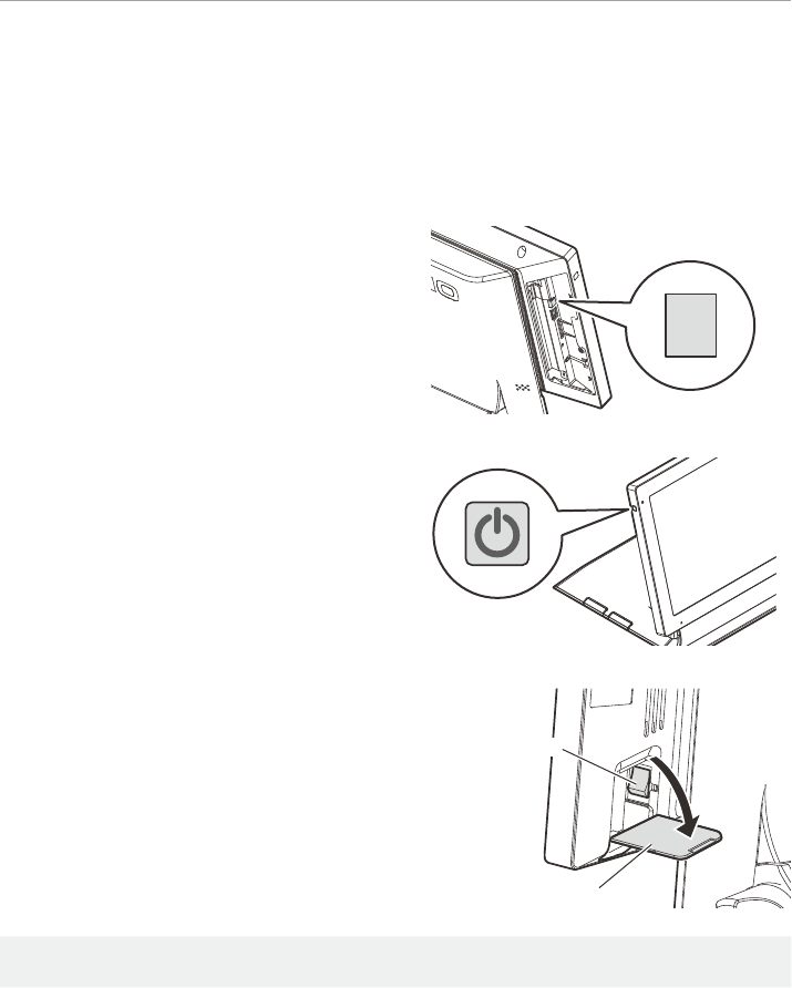
When moving or cleaning the product, always shut down the main unit before turning
OFF the main power switch. Also, always make sure that the main power switch is OFF
before removing or inserting the plug.
1. Shut down the main unit.
Using the OFF Switch
(1) Press and hold the OFF switch for
approximately 1 second.
(2) Touch the “Power off” display.
Using the Power Switch
(1) Press and hold the power switch for
10 seconds or longer.
(2) Touch the “Power off” display.
2. Turn the main power switch OFF.
Remove the main power switch cover
and turn OFF the main power switch.
+The data may be damaged when above procedure is not done properly. Do not use the
main power switch to turn the main unit ON/OFF during normal use.
3. Remove the power plug.
4. After moving or cleaning the product,
plug in the power plug and switch ON
the main power switch.
OFF
Main power switch
Main power switch cover
Basic Operation
E-17
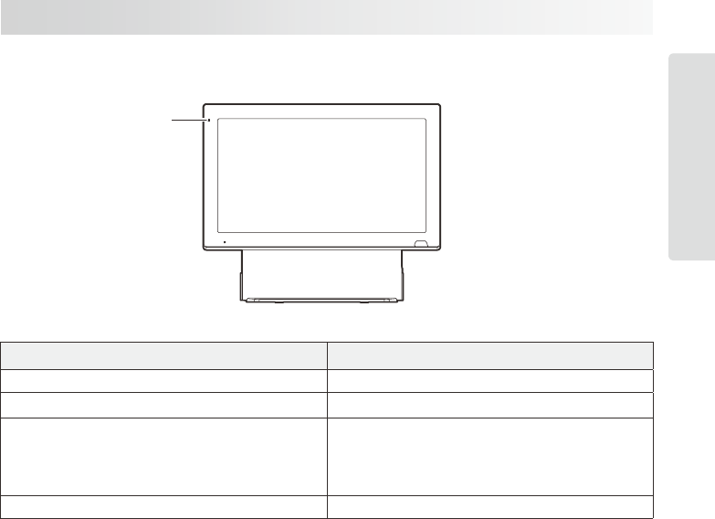
Description of the Indicator
The status is indicated by the ON, ashing, or OFF of the indicator.
Indicator
Indicator Status
Green light is ON Power is ON/screen is ON
Orange light is ON Power is ON/screen is OFF
Green and red lights ashing with screen ON
Red and orange lights ashing with screen OFF
Memory protection battery not charged
*Do not turn OFF the main power switch or
remove the power plug with the display in this
state.
OFF Power is OFF (shutdown)
E-18
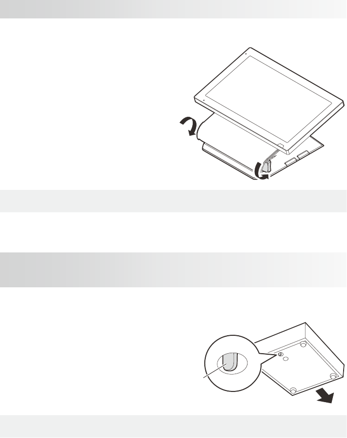
Adjusting the Angle of the Display
Adjust the angle of the display to the appropriate position for comportble operation.
1. Loosen the tilt knob in the direction
indicated in the illustration for 1 rotation
or more and raise the top of the stand.
+Take caution not to pinch nger with the tilt knob and its surrounding when adjusting the
angle of the display. There may be a risk of injury.
When the Drawer Does not Open
(if using the optional CASIO drawer)
If the drawer fails to open due to a power cut or fault, open it by doing the following.
If you are using a CASIO optional M
size drawer, it can be opened by moving
the drawer release lever (tab on drawer
bottom).
+The drawer will not open if it has been locked with the drawer lock key. Unlock the lock.
If you are using a CASIO optional L size drawer, it can be opened by turning the drawer
key in the drawer lock.
Drawer opening lever

Installation
E-19
Installation
This chapter is about the installation. Please read these instructions before starting
installation. During use of the product, read these instructions if you have disconnected
the cables of the product to move it and do not know how to reconnect them.
Name of Parts and What They Do .....................................E-20
Connecting the Power Supply and Various Devices ......................E-22
Connecting the Drawer cable ........................................E-22
Connecting the AC Adaptor ..........................................E-23
Connecting Other Devices...........................................E-23
Preparing the Stand................................................E-25
Setting the Stand and the Display .....................................E-26
Installation features . . . . . . . . . . . . . . . . . . . . . . . . . . . . . . . . . . . . . . . . . . . . . . . . E-28
MCR Unit (VA-B46MCRE) Installation..................................E-29
E-20
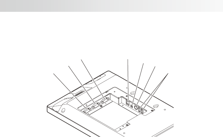
Name of Parts and What They Do
<Left side on the back of the display>
16
17
18 19 20 21
22
16 COM3 port Connect device such as customer display, etc.
17 COM2 port Connect device such as printer, etc.
18 COM1 port Connect device such as printer, etc.
19 Drawer port for 24 V Connect the drawer cable.
20 Drawer port for 5 V Connect the drawer cable.
21 DC jack Connect the AC adaptor.
22 USB (host) port Connect the USB device.
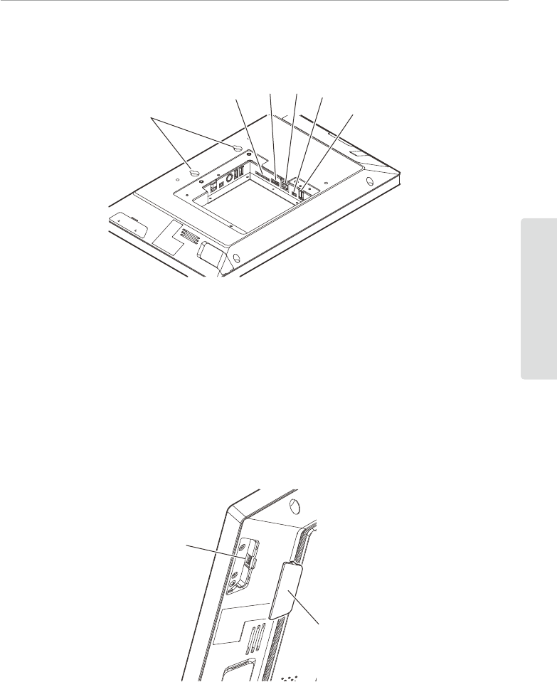
Name of Parts and What They Do
E-21
Installation
<Right side on the back of the display>
24 25 26 27
28
23
23 Mounting holes Hook onto the hook of the stand when using the stand.
24 SD/SDHC memory card slot Insert the SD or the SDHC memory card.
25 HDMI port Connect the HDMI device.
26 LAN port Connect the LAN cable.
27 Micro USB (client) port Connect the micro USB device.
28 USB (host) port Connect the USB device.
<MCR Unit Installation Parts>
29
30
29 MCR unit connector Connect the MCR unit connector.
30 MCR unit cover Cover the MCR unit connector.
E-22
Connecting the Power Supply and Various Devices
Connect the power supply and devices to be used.
+Keep the main power switch in OFF position until all the connections are completed.
●Use a Phillips screwdriver and pliers to make the connections. Prepare in advance.
● Work with the touch screen panel grounded on the oor. Place a cloth or paper in
advance so the panel will not get dirty or scratched.
POINT
When using an optional printer, SD card and HDMI device, connect them in the follow-
ing order. The devices we recommend that you connect rst have large connectors. If
you do not connect these rst, they may be obstruct the connection of other devices
and prevent such work being performed.
Order of Connection
1. Devices connecting to the COM1, COM2, and COM3 ports
2. SD card
3. HDMI
4. Other
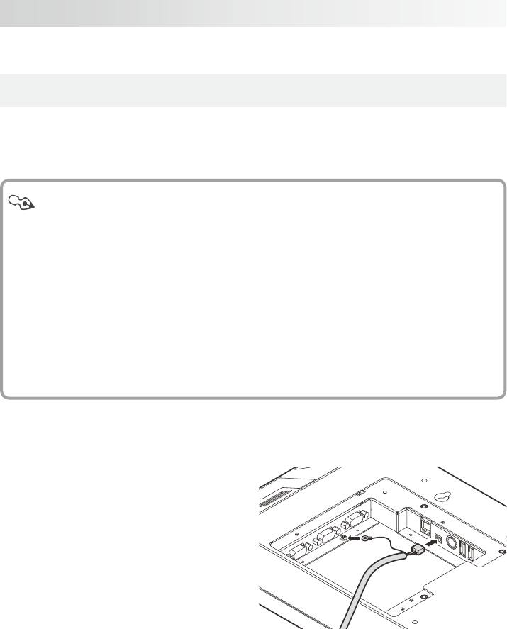
Connecting the Drawer cable
1. Connect the ground wire to the ground
terminal located within the back of the
display, and then connect the drawer
cable to the drawer port.
Connecting the Power Supply and Various Devices
E-23
Installation
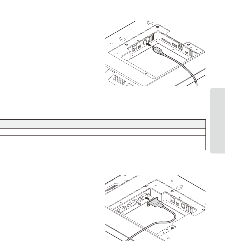
Connecting the AC Adaptor
2. Route the cable through the stand and
connect the AC adaptor to the DC jack
located within the back of the display.
Connecting Other Devices
Connect the optional device to the following connector.
Option Connector
Remote printer: UP-400B, UP-370B COM1,COM2,COM3 port
Customer display: VA-B60D COM2,COM3 port
Expansion I/F box: VA-B20EB USB host port
●For details, refer to the User’s Manual for each option.
Connecting the Printer Cable
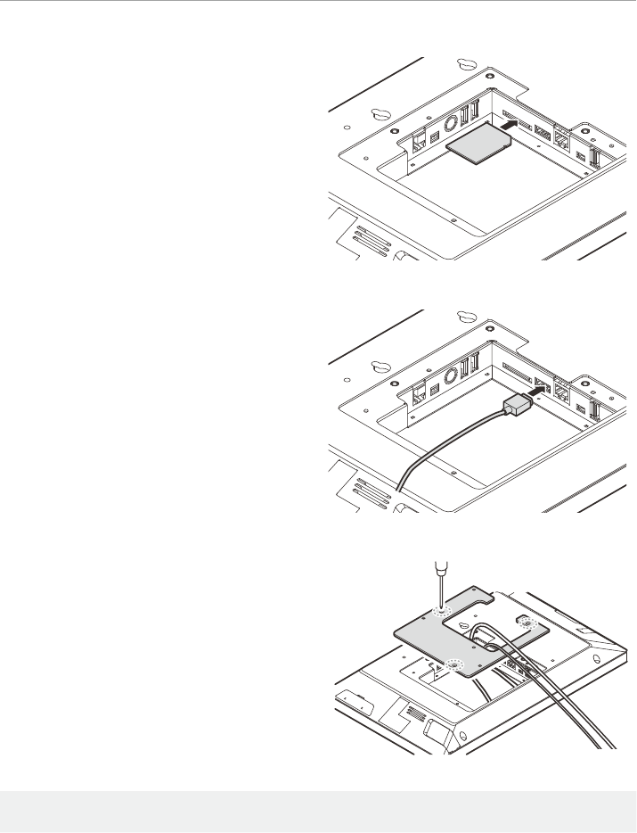
(1) Connect the printer cable plug with
screws to the COM1 port located within
the back of the display.
E-24
Connecting the Power Supply and Various Devices
Insert the SD Card
(1) Insert the SD card, front-side up, into
the SD/SDHC memory card slot located
within the back of the display.
Connecting the HDMI Device
(1) Connect the HDMI cable to the HDMI
port within the back of the display.
3. After completing the connection of
all devices you plan to use, install
the supplied connector cover with 3
screws.
+During installation, take care not to trap the connected cable between the connector cover
and the display.
Connecting the Power Supply and Various Devices
E-25
Installation
Preparing the Stand
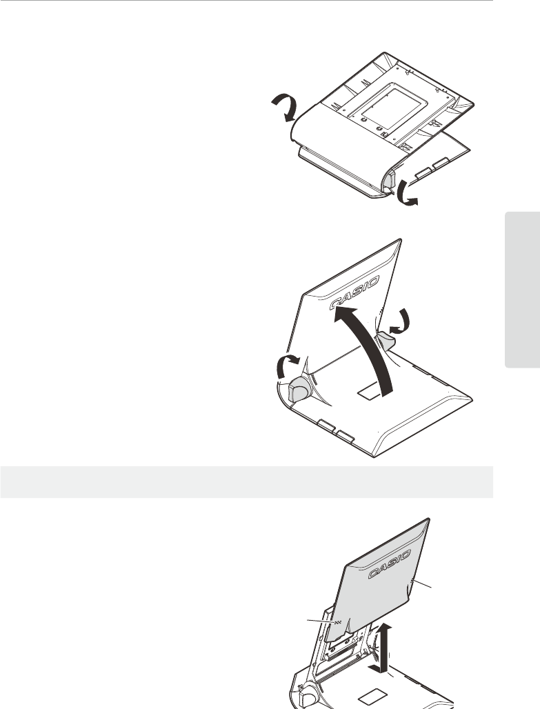
1. Loosen the tilt knobs by turning them
through at least 1 full rotation in the
directions shown.
2. Raise the upper part of the stand.
Then, while holding it steady, secure it
by tightening the tilt knobs one side at a
time in the directions shown.
+Always loosen the tilt knob when moving the stand. Moving without loosening the tilt knob
will result in malfunction.
3. Remove the rear cover by pressing at
the locations marked “A” and sliding in
the direction of the arrow.
A
A
E-26
Connecting the Power Supply and Various Devices
Setting the Stand and the Display
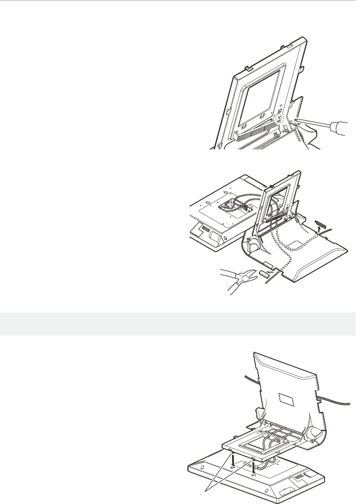
1. Loosen and remove the screw for the
cable fastener at the bottom of the
opening of the stand with a Phillips
screwdriver.
2. Route the connected cables into
the stand, passing them through the
opening. Remove the cutouts at the 4
locations in the stand base with pliers
and pull the cables through.
+Do not insert ngers into the cutout. This may result in injury.
3. Hook the display onto the tab on the
stand and adjust the routed cables so
they will not sag too much or be too
tight. Arrange the cables so they will
not overlap, and fasten with the cable
fastener and secure with a screw.
Hook
Connecting the Power Supply and Various Devices
E-27
Installation
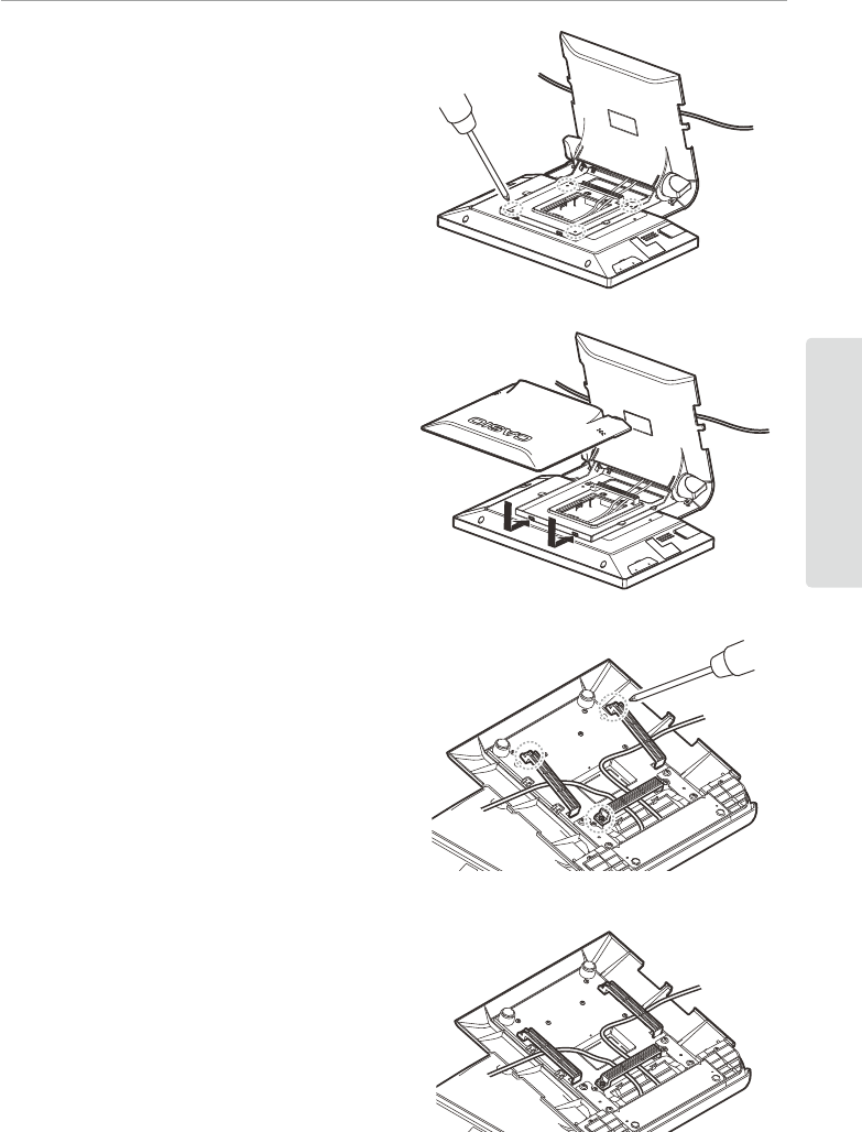
4. Fasten the stand to the display with 4
screws.
5. Attach the rear cover to the stand in the
direction of the arrow.
6. Loosen and remove the screws for the
3 cable fasteners at the bottom of the
stand with a Phillips screwdriver.
7. Adjust the routed cables so they will not
sag too much or be too tight. Arrange
the cables so they will not overlap,
and fasten with the cable fastener and
secure with a screw.
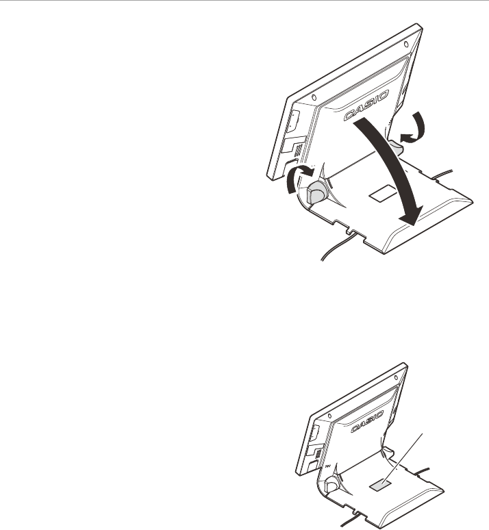
E-28
Connecting the Power Supply and Various Devices
8. Raise the display. Then, while holding
it steady, secure it by tightening the
tilt knobs one side at a time in the
directions shown.
9. Connect the AC adaptor with the power
cord, and plug into a power outlet.
Installation features
• A screen for customers can be installed.
To do so, remove the cutout in the base
of the stand with pliers.
Cutout
Connecting the Power Supply and Various Devices
E-29
Installation
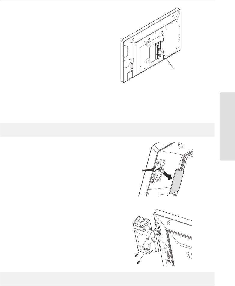
• The display may be wall-mounted. In this
case, the stand is not used.
For further details, contact the CASIO service representative.
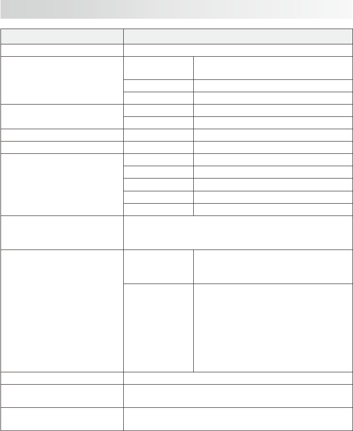
MCR Unit (VA-B46MCRE) Installation
+Before installation, be sure to turn the main power switch OFF and remove the plug from
the power outlet.
(1) Remove the MCR unit cover with a
Phillips screwdriver etc. and connect
the MCR unit connector.
(2) Install the MCR unit as shown in the
illustration and secure it with 2 screws
(supplied).
+During installation, take care not to trap the connected cable between the MCR unit and
the display.
For how to install a printer or other optional device, refer to the Operating Instructions
supplied with the optional device.
Screw holes for wall-mounting
E-30
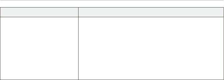
Specication
Item Specication
Model
Display Type 15.6 inch WXGA color TFT liquid crystal
display
Resolution 1366 x 768
Backlight White LED
Touch panel Method 4-wire resistive lm
Size 15.6 inch
Wireless LAN (V-R7100 only) Standard IEEE 802.11a/b/g/n
Bluetooth (V-R7100 only) Supported version Bluetooth standard Ver2.0+EDR
Memory protection Battery Lithium ion rechargeable battery
Memory holding Approximately 24 hours (used at 25°C)
Time holding Approximately 30 days
Battery life 5 years (used at 25°C)
Charge time Full charge in 3 hours (used at 25°C)
Power supply/power consumption 120 V ac ±10 V 50/60 Hz 0.5 A
230 V ac ±10 V 50/60 Hz 0.3 A
220 V to 240 V ac ±10 V 50/60 Hz 0.3 A
External interface
Side of display
SD/SDHC memory card slot x 1
USB host port x 1
Earphone jack x 1
Rear of display
COM port x 3
Drawer port x 2
DC jack x 1
USB host port x 3
SD/SDHC memory card slot x 1
HDMI port x 1
LAN port x 1
Micro USB client port x 1
Temperature/humidity (operation) 0°C to 40°C/10% to 90% RH
External dimensions W 400 mm x D 300 mm x H 335 mm
W 400 mm x D 45 mm x H 250 mm (display only)
Weight Approximately 7.0 kg
Approximately 3.5 kg (display only)
V-R7100-C,V-R7100
E-31
Specication
Item Specication
Option Remote printer: UP-400B, UP-370B
Customer display: VA-B60D
Customer display serial cable (40 cm): QT-6061CB-B
Customer display serial cable (5 m): QT-6062CB-B
Expansion I/F box: VA-B20EB
Drawer (M size): DL-2814, DL-2815, DL-2436
(L size): DL-3624, DL-3625
Drawer extension cable: VA-B30CB
MCR unit: VA-B46MCRE

MEMO
E-32
