Casio 1794 1790, Quiet Flo Electric Fuel Pumps For EFI User Manual To The A6266ce2 E5c0 495e 8dda 978ad5d0556a
User Manual: Casio 1794 to the manual
Open the PDF directly: View PDF ![]() .
.
Page Count: 2
©2005 Edelbrock Corporation
Brochure # 63-0171
Page 1 of 2
Catalog #1790, #1794
Rev. 2/05 - RS/mc
Edelbrock Quiet-Flo Electric Fuel Pumps For EFI Applications
Catalog #1790 (80 gph) & 1794 (120 gph)
INSTALLATION INSTRUCTIONS
®
PLEASE study these instructions completely and thoroughly before installing your new Fuel Pump. If you have any questions or problems, contact
our Technical Hotline at: 1-800-416-8628, 7 am - 5 pm Monday-Friday, Pacific Standard Time or e-mail us at edelbrock@edelbrock.com.
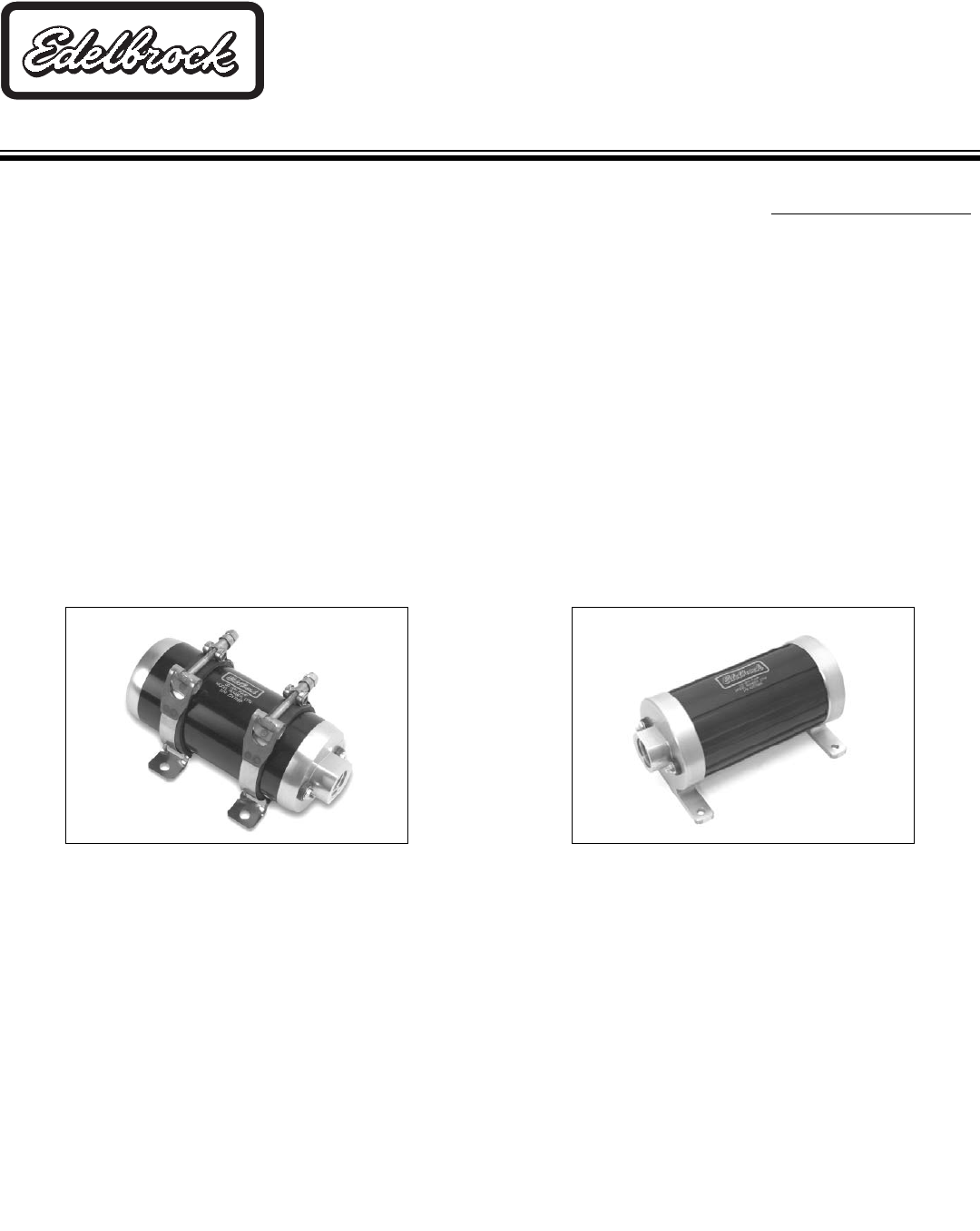
DESCRIPTION: Edelbrock Quiet-Flo Electric Fuel Pumps feature anodized aluminum housings and high quality internal construction, making them
strong, durable, and quiet. #1790 features a -10 AN inlet/outlet, while #1794 features a -12 AN inlet/outlet. Both pumps are compatible with all
grades of gasoline and methanol type fuels. Performance Specifications are listed below.
CAUTION!
Installation of this product should be performed by persons knowledgeable in the repair and modification of high pressure automotive fuel systems.
Do not loosen fuel system connections until relieving fuel pressure as recommended in your automotive service manual. Fuel leakage
will occur when loosening fuel system connections, eliminate potential fire hazards before loosening any fuel system connections.
PERFORMANCE SPECIFICATIONS:
1790 1794
Outlet Pressure/Flow 45 psi/80 gph (480 lbs/hour) @ 12 Volts 45psi/120gph (720 lbs/hour) @ 12 Volts
Maximum Pressure 90 psi 100 psi
Current Draw 12.5 amps @ 45 psi 14.5 amps @ 45 psi
Conversions: 1 gallon gasoline = 6.0 lbs (average) 1 bar = 14.5 psi
1794
1790
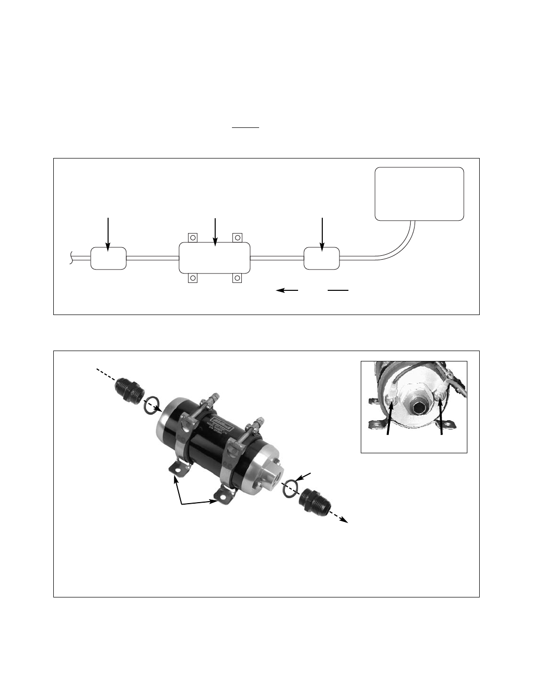
INSTALLATION:
NOTE: The use of a pre-filter (60 micron maximum) is needed before the fuel pump, and a 10 to 30 micron (maximum) is needed after the fuel
pump. If a pre-filter is not used, early fuel pump failure can/will occur. See Figure 1.
IMPORTANT: When choosing pump location, make sure to mount the fuel pump at or below the level of the bottom of the fuel tank. This will
ensure that the fuel pump will have a head of fuel pressure on the inlet side to aid in priming the fuel pump. Damage to the pump will occur if
the pump is mounted incorrectly. See Figure 1.
1. With the ignition “off” and engine cool, relieve the fuel system pressure.
2. Disconnect the existing fuel pump lines. Plug the open fuel lines to prevent foreign matter from entering the fuel system. Remove
existing fuel pump.
3. Determine the new fuel pump mounting location. Remember, the fuel pump must be mounted at or below the bottom of the fuel
tank.
4. Replace existing fuel lines as necessary for proper fitment. Use existing bracket holes, if possible. Otherwise, for #1790, mark and
drill mounting bracket holes using the brackets as a template. On 1794 fuel pumps, the mounting brackets are integral to the body
of the fuel pump. Hold the fuel pump in position and use the mounting holes as your template.
5. Assemble the bracket and fuel pump (On 1794, bracket assembly is not required).
©2005 Edelbrock Corporation
Brochure # 63-0171
Page 2 of 2
Catalog #1790, #1794
Rev. 2/05 - RS/mc
Edelbrock Corporation • 2700 California St. • Torrance, CA 90503
Tech-Line: 800-416-8628 • E-Mail: Edelbrock@Edelbrock.com
EFI Fuel Pump #1790:
Requires two -10 fittings.
(Not Included)
Russell Part #670710
EFI Fuel Pump #1794:
Requires two -12 fittings.
(Not Included)
Russell Part #670730
RED +BLACK -
O-Ring
6. Install the fuel pump and bracket assembly in the desired location. Make sure the pump is facing the proper direction. The outlet
is on the same side as the fuel pump’s electrical connections
(See Figure 2).
7. Pump Wiring:
NOTE: A RELAY IS RECOMMENDED FOR PROPER OPERATION. Edelbrock offers a 30 amp universal electric fuel pump relay, part
#1795. Wiring instructions are included with the fuel pump relay.
If a relay is not being used, connect a BLACK 12-gauge wire to the negative (-) terminal on the fuel pump, and to a quality ground
location (Engine ground or negative battery terminal is recommended). Connect a RED 12-gauge wire (+) from a 12v key-on
switched connection, such as a 30 amp relay, to the positive terminal on the fuel pump. Check to make sure power is only on when
the key is on. Recommended 30 Amp inline fuse.
8. Install the o-rings and fittings (fuel fittings and O-rings not included)
(See Figure 2)
and connect to your fuel lines.
9. Check for leaks: Turn ignition to the “Run” position without starting the engine and check all connections for leaks. If any leaks
exist, immediately turn key off and repair leaks before continuing.
Figure 2 - Fuel Pump Fitting Assembly (1790 Shown)
*Mounting brackets are integral to the body of
fuel pump #1790. No assembly is necessary.
Figure 1 - Typical Fuel System Layout (Supply Side)
Fuel Filter
10-30 Micron
Recommended
Pre-Filter
60 Micron
Recommended
Fuel Tank
Fuel Pump
Flow
Mount At or
Below Bottom
of Fuel Tank
Red
Black
Fuel In
1790: -10 AN
1794: -12 AN
Fuel Out
1790: -10 AN
1794: -12 AN
Mounting
Brackets*
