Casio IT G400 EN
User Manual: Casio IT-G400 IT-G400 | Handheld Terminals | Manuals | CASIO
Open the PDF directly: View PDF ![]() .
.
Page Count: 51
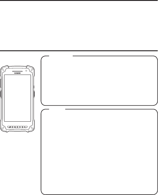
Rugged Smart Device
User’s Guide
Series
Be sure to read “Safety
Precautions” inside this
guide before trying to use
your Smart Device.
E

Trademarks and Licenses
Bluetooth is a registered trademark owned by Bluetooth SIG, Inc. and licensed to CASIO
COMPUTER CO., LTD.
Google™, the Google logo, Android™ and the Android logo are trademarks or registered trademarks of Google Inc.
SD, SDHC, microSD and microSDHC are trademarks of SD-3C LLC.
FeliCa is a registered trademark of Sony Corporation.
All other company or product names mentioned herein are trademarks or registered trademarks of their respective owners.
This product uses software licensed on the basis of GNU General Public License (GPL), GNU Lesser General Public
License (LGPL) and other licenses. Relevant terms and conditions shall also apply to this software.
For details on licenses, see “Settings” → “About terminal/device ” → “Legal information” →“Open source licenses”.

E-1
Contents
Warning Label ............................................................................................... E-2
Safety Precautions ....................................................................................... E-3
Operating Precautions ................................................................................. E-7
Regulatory Information ................................................................................ E-8
About the Waterproofi ng/Dustproofi ng...................................................... E-9
Important ..................................................................................................... E-10
Accessories and Options ........................................................................... E-10
Part Names .................................................................................................. E-11
Getting Ready to Use ................................................................................. E-13
Attaching the screen protect sheet .......................................................... E-14
Installing and Replacing the Battery Pack ............................................... E-14
Installing and Removing the AC Adapter ................................................. E-17
Charging the Battery Pack ......................................................................... E-18
Attaching the Strap ..................................................................................... E-21
Attaching the Stylus (Pen) .......................................................................... E-22
Using the C-MOS Imager ........................................................................... E-23
Using a SIM Card ........................................................................................ E-24
Using a microSD Card ................................................................................ E-25
Handling the NFC ........................................................................................ E-26
Performing Communications .................................................................... E-27
Turning the Power On/Off and Sleep ........................................................ E-29
Rebooting or Resetting the Smart Device................................................ E-30
IT-G400 Specifi cations ............................................................................... E-31
Installing and Removing the AC Adapter for the USB and LAN Cradles
..... E-36
USB Cradle (HA-R60IO) .............................................................................. E-37
LAN Cradle (HA-R62IO) .............................................................................. E-40
Four-cradle Battery Charger (HA-R38CHG) ............................................. E-43
Four-bay Battery Charger (HA-R34CHG) .................................................. E-45
USB Cable (HA-R81USBC) ......................................................................... E-47
Using Rechargeable Battery Packs .......................................................... E-48

E-2
Warning Label
• This label is a warning and caution label for Class 2 laser products that comply with
IEC60825-1:2014.
• Although Class 2 laser light is only emitted momentarily, never look directly into the
beam light.
• The laser light emitted by this laser scanner has a maximum output of less than 1 mW
and a wavelength of 650 nm.
• Use of controls or adjustments or performance of procedures other than those specifi ed
herein may result in hazardous radiation exposure.
• Toute manipulation a l'aide de procedures autres que celles specifi ees dans ce Mode
d’emploi est dangereuse et doit etre evitee.
E-3
Safety Precautions
Congratulations upon your selection of this CASIO product. Be sure to read the following
Safety Precautions before trying to use it for the fi rst time.
Your neglect or avoidance of the warning and caution statements in the subsequent
pages causes the danger of fi re, electric shock, malfunction and damage on the
goods as well as personal injury.
Markings and Symbols
The following are the meanings of the markings and symbols used in these Safety
Precautions.
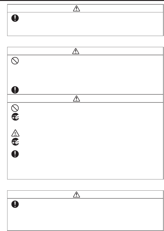
Danger This symbol indicates information that, if ignored or applied incorrectly, creates
the danger of death or serious personal injury.
Warning This symbol indicates information that, if ignored or applied incorrectly, creates
the possibility of death or serious personal injury.
Caution This symbol indicates information that, if ignored or applied incorrectly, creates
the possibility of personal injury or property damage.
• A diagonal line indicates something you should not do. The symbol shown here indicates you
should not try to take the unit apart.
• A black circle indicates something you should do. The symbol shown here indicates you
should unplug the unit from the wall outlet.
E-4
Warning
Disassembly and Modifi cation
• Never try to disassemble or modify the Smart Device and its options including battery pack
and battery in any way.
Abnormal Conditions
•
Should the Smart Device and/or its options including battery pack and battery become hot or
start to emit smoke or a strange odor, immediately turn off the power and contact your dealer
or distributor whom you purchased the product from, or an authorized CASIO PA repair
center.
Warning
Dust and Moisture
• Though the Smart Device is dust- and waterproof structure, its options including the battery
pack are not. Keep loose metal objects and containers fi lled with liquid away from your
Smart Device and the options. Also, never handle the Smart Device and the options while
your hands are wet.
Laser Light
• This product uses laser light. Never look directly into the laser light or shine the laser light
into the eyes.
• Ce produit utilise une lumière laser. Ne regardez jamais directement la lumiere laser ni ne
dirigez la lumiere laser dans les yeux de quelqu'un.
Warning
Interference with the Operation of Other Equipment
(Using Wireless Data Communication)
• Keep your Smart Device well away from anyone wearing a pacemaker. Radio waves
emitted by the Smart Device can affect the operation of a pacemaker.
• Before the use in aircraft, be sure to consult with cabin crew for interference the Smart
Device emits.
• Before the use in medical facility, be sure to consult with the facility management or the
manufacture of a specifi c medical equipment that the Smart Device may interfere with.
• Do not use the Smart Device nearby gas pump or chemical tank or any other places
fl ammable or explosive.
E-5
Caution
Foreign Objects
• Take care to ensure that metals or combustible objects are not inserted into the openings of
the Smart Device or its options, and not to allow moisture to get inside of them.
Location
• Install the cradle properly on a fl at and stable surface so that it cannot fall down onto fl oor.
LCD Screen
• Never apply strong pressure to the screen or subject it to strong impact. Doing so can crack
the LCD Screen.
Low Temperature Burn
• Avoid prolonged contact with the skin while the Smart Device is switched on. Some areas
on the back of the Smart Device may become hot during use and could cause low-
temperature burns.
Volume
• When using the headphones, adjust the volume to a suitable level. High volume can cause
damage to your hearing.
LED Light
• Do not aim the LED light at anyone’s eyes at a close range. Failure to do so could cause
visual impairment or other damages.
Lithium-ion Battery Pack
Danger
• Never use the Smart Device and its option including the battery pack and battery next to
open fl ame, near a stove, or any other area exposed to high heat, or leave them for a long
period of time in a vehicle parked in direct sunlight.
• Never use the battery pack with any device other than the Smart Device.
• Never dispose of the battery pack by incinerating it or otherwise expose it to heat.
• Never transport or store the battery pack together with metal objects that may result in
shorting positive (+) and negative (–) terminals of the battery pack. Be sure to place the
battery pack in its case whenever transporting or storing it.
• Never throw the battery pack or otherwise subject it to strong impact.
• Never pierce the battery pack with nails, hit it with a hammer, or step on it.
• Use only the specifi ed battery charger to charge the battery pack.
Warning
• Never place the battery pack in a microwave oven or any other high-voltage device.
• If the amount of time period the battery pack can serve becomes considerably short even
after it has been fully charged for the specifi ed time period, stop using it.
• Should the battery pack start to leak or emit a strange odor, immediately move it away from
any fl ame nearby. Leaking battery fl uid is combustible.
• Should fl uid from the battery pack accidentally get into your eyes or on the skin, do not rub
it. Immediately rinse it off with clean tap water and then consult a physician.
E-6
Caution
• Replace only with the same type of battery pack recommended by CASIO. Dispose of used
battery packs according to the local regulation.
• Keep the battery pack out of the reach of small children.
• Risk of explosion if battery is replaced by an incorrect type. Dispose of used batteries
according to the instructions.
Power Supply / AC Adapter
Warning
• Do not use the Smart Device at a voltage other than the specifi ed voltage. Also, do not
connect the Smart Device to a multi-plug power strip.
• Never modify, sharply bend, twist, or pull on the power cord.
• Never use a detergent to clean AC adapter and its power cable, especially on the plug and
the jack.
• Do not use an AC adapter with a bent connector.
• Do not twist or wrench the connector.
• When using the battery chargers and the cradles, be sure to use the respective AC adapters.
Caution
• Never pull on the power cord when unplugging it.
• Never touch the plug while your hands are wet.
• Be sure to unplug the power cord from the wall outlet before cleaning the battery chargers
and the cradles.
• Unplug the power cord from the wall outlet whenever leaving the battery chargers and the
cradles unattended for a long period.
• The housing of the AC adapter can become warm during normal use.
• At least once a year, unplug the AC adapter from the wall outlet and clean any dust that
builds up between the prongs of the plug.
Dust built up between the prongs can lead to the danger of fi re.
• Check that the connector is properly oriented and then push it straight in (do not insert
upside down).
• Do not allow fl uids or foreign objects to get into the AC adapter.
• Choose a location where the power cord is readily accessible and can be easily plugged in
and unplugged.
• When using the AC adapter, always use a power outlet with the specifi ed power supply and
voltage, and ensure that the power plug is inserted into the socket fully and securely.
Backup of All Important Data
Caution
• Note that CASIO Computer Co., Ltd. shall not be held liable to you or any third party for any
damages or loss caused by deletion or corruption of data due to use of the Smart Device,
malfunction or repair of the Smart Device or its peripherals, or due to the batteries going dead.
• The Smart Device employs electronic memory to store data, which means that memory
contents can be corrupted or deleted if power is interrupted due to the batteries going dead
or incorrect battery replacement procedures. Data cannot be recovered once it is lost or
corrupted. Be sure to make backup of all important data.
E-7
Use Casio genuine battery pack only
Danger
•
We recommend the use of Casio genuine battery packs with Casio devices. Casio genuine
battery packs are tested for quality and safety for the safe use of the product they are installed.
We cannot be held liable for accidents or damages caused by counterfeit Casio battery
packs or battery packs other than Casio genuine battery packs. When buying a battery pack,
pay due attention to buy a Casio genuine battery pack.
Operating Precautions
Your Smart Device and its options are precision. Improper operation or rough handling can
cause problems with data storage and other problems. Note and observe the following
precautions to ensure proper operation.
• Do not continue using the battery once it is exhausted.
Doing so could result in data loss or corruption. When the battery is exhausted, replace it
immediately.
• Stop or avoid using the Smart Device and its options in areas and conditions subject
to the following.
— Large amounts of static electricity
— Extreme heat or cold or humidity
— Sudden temperature change
— Large amount of dust
— After large amount of rain or water falls on the Smart Device
— Pressing the screen or keys with excessive force when using in the rain
• Pens other than the stylus (pen) bundled with this product will not operate correctly
with the Smart Device.
• Touch panel (screen)
— The stylus (pen) and glove cannot be used while the Smart Device is being charged
using the AC adapter or cradle.
• Do not use volatile chemical substances such as thinners, benzene or toiletries to
clean the Smart Device.
When the Smart Device is dirty, wipe it clean with a soft, dry cloth. Rubbing with
excessive force could scratch the display.
• The power-supply terminals and Data Communication terminals should be cleaned
periodically using an implement such as a dry cotton bud.
Soiling on the terminals may cause connection defects.
• Take care when using chemicals.
Applying thinners, gasoline, kerosene, solvents or oils, or substances such as cleaners,
adhesives, paints, medications or toiletries that contain those materials, to the plastic case
or cover may cause discoloration or other damage.
• LCD panel
The following are characteristics of the LCD panel and do not indicate a fault.
— The LCD panel is manufactured using high-precision technology and features a
minimum of 99.99% effective pixels. There may be some pixels that fail to light or that
remain permanently lit.
— If the same screen is displayed on the panel for a prolonged period, its afterimage may
persist after a new screen is displayed. The afterimage will fade after a few moments.

E-8
• 802.11a/n Restrictions
— This product is for indoor use only when using channels 36, 40, 44, 48, 52, 56, 60, or
64 (5150-5350 MHz).
— To ensure compliance with local regulations, be sure to select the country in which the
access point is installed.
• Do not use a strap other than the one supplied.
• Weld lines
There are seam-like markings in some locations on the battery pack. These are referred to
as “weld lines” in the plastic forming process and are not cracks or scratches. Weld lines
do not interfere in any way with the operation of the battery pack.
• If the battery pack is removed from the Smart Device without fi rst shutting down or
switching to Hot Swap mode, the time may be reset.
• Lithium-ion Battery Pack
Each lithium-ion battery pack has its life. The life span heavily depends on how the battery
pack is charged or stored which may cause deterioration of the battery pack to shorten the
life span if it is handled improperly. Note the tips below to make the battery pack last long.
— Be sure to charge the battery pack before using it if the battery pack is used for the fi rst
time or if it has not been used for a long period of time. When charging the battery
pack, continue charging until the charge LED lights green (fully charged).
— If the battery pack is repeatedly charged, the life span becomes short. To avoid the
repetition of charging the battery pack, be sure that the remaining capacity is low
before you start charging.
— Be sure to charge the battery pack in recommended temperature range. The temperature
range is dependant on device you use to charge including battery chargers and tablets.
(download version). Charging the battery pack in a temperature outside of the
recommended range causes deterioration.
— When used at low temperatures, the battery pack has a reduced capacity and will
supply power for shorter time. The life span of the battery pack is also shortened.
— Charging the battery pack while the battery pack itself is freeze including inside causes
deterioration. Be sure to resume an ordinary room temperature on the battery pack and
then leave it unattended for approximately one hour before charging.
— After charging the battery pack, if the performance of the battery pack does not show
any recovery, it is a sign of ending the life. Replace it with a new battery pack.
— Avoid the battery pack with a full of the capacity to store for a long period of time. If
you need to store it for a long period, be sure that the remaining capacity is 30 to 50
percent and to store in a moderate low temperature. This can reduce deterioration.
—
The battery pack gradually deteriorates over time. In particular, storing (or using) the fully
charged battery pack at high temperatures tends to accelerate battery pack deterioration.
• Drop resistance
The drop resistance is a test value only and is not guaranteed.
Repeated or frequent shocks may still result in damage, so the Smart Device should be
handled so as to avoid impacts.
Regulatory Information
Europe
Manufacturer:
CASIO COMPUTER CO., LTD.
6-2, Hon-machi 1-chome, Shibuya-ku, Tokyo 151-8543, Japan
Importer
Casio Europe GmbH
Casio-Platz 1, 22848 Norderstedt, Germany
www.casio-europe.com
IT-G400
Options of IT-G400

E-9
• Please keep all information for future reference.
• The full text of the EU declaration of conformity is available at the following internet address:
http://doc.casio.com/
• Products are for distribution within all member states of the EU.
• Options of IT-G400 are HA-R60IO, HA-R38CHG, HA-R34CHG, AD-S10050B, HA-R20BAT,
HA-R21LBAT, HA-R22BC, HA-R24LBC, HA-R81USBC, AC-CORD3-EU, AC-CORD3-UK,
HA-R62IO
For Europe models are IT-G400-C21M, IT-G400-C21L, IT-G400-WC21M, IT-G400-WC21L
Hereby, “CASIO COMPUTER CO., LTD.” declares that the radio equipment type “IT-G400” is
in compliance with Directive 2014/53/EU.
About the Waterproofi ng/Dustproofi ng
The IT-G400 Series models are waterproof and dustproof.
Important!
The water- and dust-proofi ng performance of this product is based on CASIO testing
procedures. Note also that this performance applies to the product at the time of
shipment (delivery to the customer) and is not guaranteed inclusive of the
environment in which the product is used. The warranty does not apply to any
situation where the product is immersed during use, and as with any other electrical
product, great care should be taken when using this product in the rain or similar
situation.
• Precautions When Using this Product
— Check that there is no dust, sand or other foreign matter on the battery pack cover, or
earphone-microphone jack cover, or on the respective contact surfaces. If any soiling is
found, wipe it off with a clean, soft, dry cloth. Even very small amounts of soiling
trapped on the contact surfaces (a single hair or grain of sand, etc.) can cause water to
leak into the device.
— Check that the waterproof seals on the battery pack cover and earphone-microphone
jack cover are free from cracks and other damage.
— Close the battery pack cover lock switch fi rmly until the switch is in the locked
position.
— Avoid opening and closing the battery pack cover or earphone-microphone jack cover
in locations near water or exposed to sea breezes, and do not open or close them with
wet hands.
— Do not drop this product or leave it in locations exposed to temperatures outside the
specifi ed range. Doing so could impair its water- or dust-proofi ng.
— Do not pull on the earphone-microphone jack cover with excessive force. Doing so
could cause damage. Such damage may render the product no longer waterproof.
• Other Precautions
— The accessories for this product (battery pack, etc.) and optional products are not
water- or dust-proof.
— Subjecting this product to a severe impact could render it no longer water- or
dust-proof.
— If any water leaks into the product as a result of carelessness or inattention during
product handling, CASIO cannot be held liable for compensation for any damage to
internal components (battery, recording media, etc.) or for the costs of recorded content
or the recording thereof.
— CASIO COMPUTER CO., LTD. accepts no other liability whatsoever for any accident
that occurs due to water leakage.
E-10
Important
Information in this document is subject to change without advance notice. CASIO Computer
Co., Ltd. makes no representations or warranties with respect to the contents or use of this
manual and specifi cally disclaims any express or implied warranties of merchantability or
fi tness for any particular purpose.
After Service
• Should this product ever malfunction, contact your original retailer providing information
about the product name, the date you purchased it, and details about the problem.
Accessories and Options
Make sure all items listed below are included before using the
Smart Device for the fi rst time.
• Strap • Screen Protect Sheet • Stylus (Pen)
• AC Adapter (5V2A)
• 3 AC Adapter Plugs (Type A, BF, C)
• Battery Pack (Standard or High Capacity type according to the
Smart Device)
• User’s Guide (this manual)
• Warranty (This warranty is valid only in Japan)
• WEEE separate sheet
Accessories
Rugged Smart Device
IT-G400 Series
• USB Cradle HA-P60IO
Accessories: AC Adapter (5V4A), 3 AC Adapter Plugs (Type A,
BF, C), microUSB cable
• LAN Cradle HA-R62IO
Accessories: AC Adapter (5V4A), 3 AC Adapter Plugs (Types A,
BF, C)
• Four-cradle Battery Charger HA-R38CHG
Accessories: AC Adapter (12V5A)
• Four-bay Battery Charger HA-R34CHG
Accessories: AC Adapter (12V5A)
• AC Cord for AC Adapter (12V5A): AC-CORD3 AC-CORD3-EU
AC-CORD3-UK AC-CORD3-AU
• AC Adapter (5V2A) AD-S10050B
• Standard Battery Pack HA-R20BAT
• High Capacity Battery Pack HA-R21LBAT
• Battery Cover (for Standard Battery Pack) HA-R22BC
• Battery Cover (for High Capacity Battery Pack) HA-R24LBC
• Screen Protect Sheet HA-R95PS10
• USB Cable HA-R81USBC
Options
For the latest options list, refer to the ON-LINE manual available at
http://support.casio.com/en/manual/manual.php?cid=010
E-11
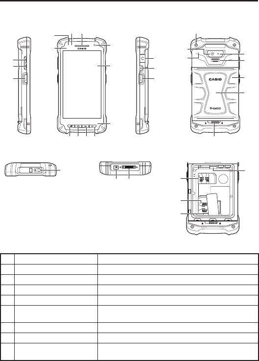
Part Names
Smart Device (IT-G400)
Top
Left Front Right Back
Battery Compartment Bottom
13
14
15
13
2
45
6
11
78910
16
17
18
19
21
23
20
22
24
25
26
12
31 32 27
29
28
30
1 Receiver Receiver for voice call
2 Charging Status LED Show charging status
3 Notifi cation LED Show notifi cations
4 Illuminance/Proximity Sensor Measure brightness and proximity of object
5 Front Camera Take picture and movie
6 Screen (Touch Panel) Display words and operation instructions
Input data in IT-G400 by fi nger or Stylus (Pen)
7 Recent Apps Key Switch applications
8 Home Key Go home screen
9 Back Key Back to previous screen
Close dialog box, option menu and notifi cation panel

E-12
10 Function Key Launch program buttun app
Able to set an optional function
11 Microphone Microphone
12 Barcode Reader Laser or LED light of 2D imager radiates to read barcode
13 Volume Up Key Volume up
14 Volume Down Key Volume down
15 L Trigger Key Scan barcode
Able to set an optional function
16 Headset Jack Connect the headset
17 Power Key Power down/power on IT-G400
18 R Trigger Key Scan barcode
Able to set an optional function
19 Camera Take picture and movie
20 LED Light Torch around and camera fl ach
21 Microphone Microphone
22 Speaker Output sound like alarm
23 Strap Holes Attach strap
24 Battery Cover Cover battery pack
25 NFC Reader Reading NFC card
26 Battery Cover Lock Switch Open battery cover by sliding
27
Standard SIM Card Slot
(IT-G400-WC21M/
IT-G400-WC21L)
Insert SIM card after remving batery pack
28 microSD Card Slot Insert microSD card card after remving batery pack
29 SAM Card Slot There is a SAM slot, but it can not be used
30 Reset Switch Cold reset
31 AC Adapter Jack Connect the dedicated AC adaptor
32 Power Supply/Data
Communication Terminal
Used to connect an optional USB cable or cradle for USB
communication and to supply power.
E-13
Getting Ready to Use
* In the step 6, be sure to charge the battery pack completely.
1. Confi rm that all the items listed on page E-10 are included in the package.
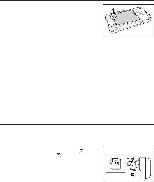
2. Remove the protective fi lm attached to the Smart
Device.
3. Attach the supplied screen protect sheet to the Smart Device. (→E-14 )
4. Install the supplied battery pack in the Smart Device. (→E-14)
5. Install the AC adapter plug in the supplied AC adapter. (→E-17)
* When using an optional product to charge, prepare the optional product accordingly.
6. Charge the battery pack. (→E-18)
7. Turn the power on. (→E-29)
8. Confi gure the initial setup.
* Begin initial setup by setting the language. In this setting, select the language to be
used.
E-14
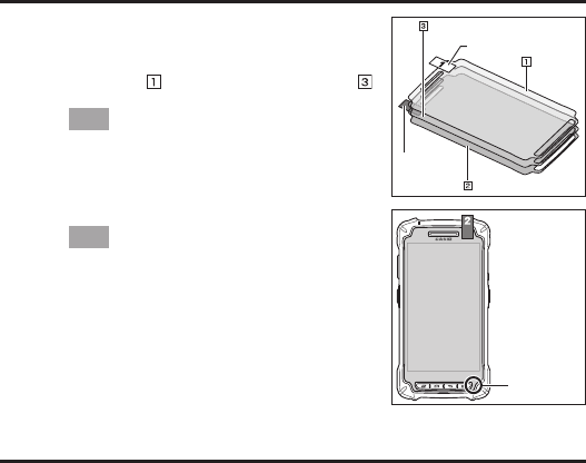
Attaching the screen protect sheet
1. Wipe off any dirt from the screen.
2. The screen protect sheet consists of 3 layers as shown
in the fi gure. Hold tape 1, and while you remove the
release fi lm ( ), attach the screen protect sheet ( )
to the Smart Device.
Tip!
Align each part such as keys or receiver with the holes
of each part in the screen protect sheet.
When attaching the sheet, take care to avoid air
bubbles.
3. Hold tape 2 and remove the release fi lm.
Tip!
Take care not to cover the microphone with the screen
protect sheet. If microphone is covered, quality of the
voice input will deteriorate.
Installing and Replacing the Battery Pack
Your Smart Device uses two types of battery: a battery pack and a memory backup battery.
The battery pack is used to power normal operations and to store data, while the memory
backup battery provides the power required to maintain memory contents when the battery
pack power is unable to supply power for some reason.
You can choose either battery pack (HA-R20BAT) or large-capacity battery pack
(HA-R21LBAT) for operating power.
The backup battery is installed inside of the Smart Device.
This guide uses the following terms to refer to the batteries.
Battery Pack: Rechargeable battery pack (HA-R20BAT or HA-R21LBAT) for normal
operations and data storage
Backup Battery: Built-in battery for memory backup
When the battery pack power goes low, immediately charge it or replace it with a charged
battery pack.
You can charge the battery pack using the AC adapter, four-bay battery charger, four-cradle
battery charger, USB cradle, or LAN cradle. See the relevant sections in this guide for the
respective options about how to use.
Release fi lm
Release
fi lm
Tape 1
Tape 2
Screen protect sheet
Microphone
E-15
Important!
Always keep backup of all important data!
• The battery pack powers normal operation and also provides power required to
maintain memory contents, while the backup battery provides backup power to
maintain memory contents. Because of this, you should not remove the battery pack
if the backup battery is dead. Removing the battery pack while the backup battery is
dead causes data in the memory to be corrupted or lost. Note that once data is lost it
cannot be recovered. Always keep backup of all important data.
• The charge of a battery pack when you purchase it may be depleted due to testing at
the factory or natural discharge during shipment and storage. Be sure to charge the
battery pack before you use it.
• The life of a battery pack is limited, and charging a battery pack causes it to
gradually lose its ability to maintain the charge. If your battery pack seems to
require charging very frequently, it probably means it is time to purchase a new one.
• If a battery pack is used past the end of its service life, it may swell up in size. In such
a case, replace the battery pack with a new one.
• It takes approximately 4 hours with the main battery pack installed in the terminal
for the backup battery to be charged fully.
• If a battery pack is installed in the Smart Device, it will still work when the battery
cover is open. However, the battery cover should be closed when using the Smart
Device in case the battery pack unexpectedly drops out and causes data loss.
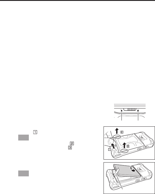
Installation
1. Turn the Smart Device over.
2. Slide the battery cover lock switch to the “Unlock”
position ( ) and remove the battery pack cover.
Tip!
After raising the protruding part ( ) on the battery
cover, raise the protruding part ( ) in the same.
Make sure the battery cover is perfectly closed in
order to maintain the waterproof performance.
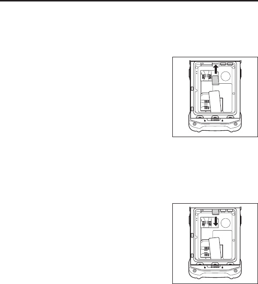
3. Install the battery pack. Make sure the battery pack is
facing the correct direction.
Tip!
Make sure to install the battery pack so that the
removal tape extends above the battery.
Slide the battery pack evenly along both sides of the
Smart Device case until the battery pack terminals are
aligned with the Smart Device power contacts.
Installing the battery pack incorrectly may distort the
battery terminal springs on the Smart Device.
Unlock Lock
Removal tape
E-16
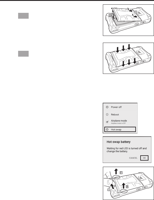
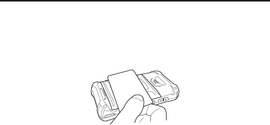
4. Return the battery cover to its original position as
shown in the fi gure.
Tip!
Confi rm that the battery cover lock switch has
returned to the “Lock” position .
Return the battery cover to its original position
without folding the removal tape over.
5. Push the battery cover to make sure it is properly
closed.
Tip!
Even when the battery cover lock switch is in the
“Lock” position, if there is a gap between the battery
cover and the Smart Device, the cover is not perfectly
closed. To maintain the waterproof performance, push
the parts indicated by arrows in the fi gure to remove
any gaps.
Precautions for Use
• Do not use any battery packs other than the specifi ed one.
Replacement
1. Turn the screen on.
2. Hold down the Power key until the Power menu is
displayed.
3. Tap “Hot swap” as shown in the fi gure.
4. Tap “OK” as shown in the fi gure and the Smart
Device will switch to the Hot Swap mode. This causes
the charging status LED to turn on red, and once
switching is completed, the charging status LED turns
off.
5. Turn the Smart Device over, slide the battery cover
lock switch to the “Unlock” position and remove the
battery cover.
E-17
6. Remove the battery pack as shown in the fi gure.
7. Install the replacement battery pack following steps 3
to 5 of the battery pack installation procedure.
Precautions for Use
• Remove the battery pack by pulling up the removal tape. Do not pull up with
excessive force as this may result in damage.
• In the Hot Swap mode, even if the battery pack is removed, your work state is saved
up to 4 minutes with the memory (RAM) backup function.
The memory (RAM) backup time may decrease depending on the backup battery
charging level.
• In the Hot Swap mode, the Smart Device will not respond even if you press the
Power key.
To exit Hot Swap mode, open the battery cover and then close it again.
• In case of replacing the battery pack without selecting the Hot Swap mode, you
cannot perform normal operations for a while.
• After replacing the battery pack, the message “Check the battery cover!!!” is
displayed. This message is displayed regardless of whether the battery cover has been
completely closed or not.
• Do not replace the SIM card or microSD card while in Hot Swap mode. Shut down
the Smart Device before replacing the SIM card or microSD card.
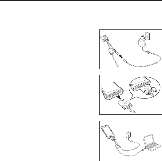
Installing and Removing the AC Adapter
You must install the adequate plug in the AC adapter for the Smart Device according to the
region where the Smart Device is used.
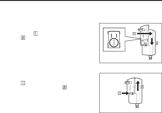
Installation
1. Insert the protruding part of the AC adapter plug into
the recessed part in the AC adapter top ( ) and push
until it clicks into place ( ).
“TOP” should be
facing upwards
E-18
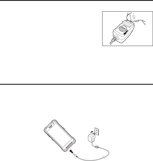
Removal
1. Pull the AC adapter plug release lever in the direction
of the arrow in the fi gure.
Precautions for Use
• When pulling the release lever, the AC adapter plug can jump out. To prevent AC
adapter plug from jumping out when pulling the release lever, hold it with a fi nger,
etc.
• Do not insert the plug only into the power outlet.
Charging the Battery Pack
You can charge the battery pack installed in the IT-G400 using the AC adapter supplied for
the Smart Device, or the optional USB cradle, LAN cradle or four-cradle battery charger.
Check charging status LED to confi rm IT-G400 charging status.
You can also use the USB cradle, LAN cradle, or four-bay battery charger to charge the
battery pack.
AC Adapter (Accessory)
AC Adapter (5V2A)
AD-S10050B
E-19
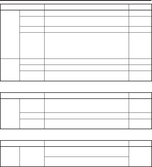
IT-G400 Charging Status LED Display
Charging status LED Charging status Remarks
Red Charging
Green Charging complete
Flashing red
Charging error
• Outside the charging
temperature range (0-50°C).
(Charging begins once the
battery pack returns to the
charging temperature range)
If this error occurs, leave the
battery pack at room
temperature for 1 hour and
charge the battery pack after it
returns to room temperature.
Flashing alternately red/green
Battery pack detection error
• Battery pack fault
• Battery pack installed
incorrectly
• Battery pack not installed
Precautions for Use
Depending on the Smart Device condition, it may take some time until the charging
status LED turns on red.
• In high- or low-temperature environments, charging may be restricted to protect the
battery pack. At such temperatures, the level of battery charge may not reach 100%
even when the charging status LED is green and charging is completed.
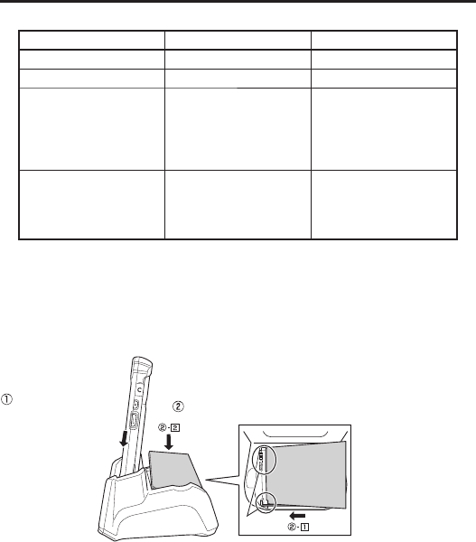
USB Cradle, LAN Cradle
Charging the battery
pack installed in the
IT-G400
Charging the battery pack
Slide the battery pack
into slots of the cradle
and align the battery
pack terminals with the
battery pack power
contacts.
Align
Cradle charging status LED display
Red: Charging
Green: Charging complete
Red/green alternate fl ashing: Standby because the battery pack is faulty, is installed
incorrectly or is outside the charging temperature range
(Charging begins when temperature returns to the charging
temperature range)
E-20
Precautions for Use
• Take care not to trap objects such as the strap in the cradle.
• The power/data communication terminal and the battery pack power contacts
should be cleaned periodically using an implement such as a dry cotton bud.
Soiling or dust buildup could cause connection problems.
Four-cradle Battery Charger Four-bay Battery Charger
AC Adapter (12V5A)
AC Adapter (12V5A)
Charging status LED display for the four-bay battery charger
Red: Charging
Green: Charging complete
Red/green alternate fl ashing: Standby because the battery pack is faulty, is installed
incorrectly or is outside the charging temperature range
(Charging begins when temperature returns to the charging
temperature range)
E-21
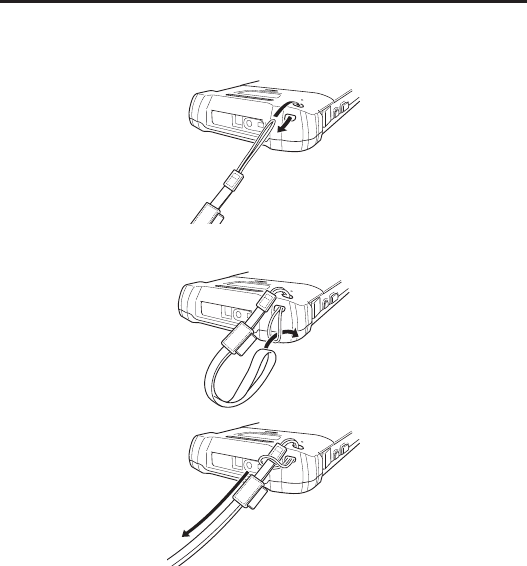
Attaching the Strap
The strap can be used to prevent the Smart Device being dropped when it is carried around.
Use the procedure below to attach the strap.
1. Thread the thin cord loop on the strap through the strap hole in the back of the Smart
Device.
2. Thread the other end of the strap (the end that goes over your wrist) through the thin cord
loop.
Precautions for Use
• Do not hold the strap and swing the Smart Device around.
E-22
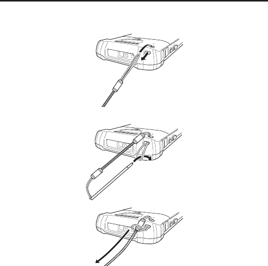
Attaching the Stylus (Pen)
Use the procedure below to attach the stylus (pen).
1. Thread the thin cord loop on the stylus (pen) through the strap hole in the back of the
Smart Device.
2. Pass the stylus (pen) tip-fi rst through the thin cord loop.
E-23
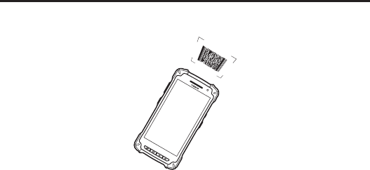
Using the C-MOS Imager
1. Turn on the Smart Device, position its C-MOS Imager reader port near the bar code or
2D code, and then press the trigger key.
2. The LED lights and the imager reads the bar code or 2D code.
If reading is completed successfully, the notifi cation LED lights blue and the read tone
sounds.
Important!
• If you have problem not properly reading a code, change the angle and/or the
distance between the code and the Smart Device and try reading it again.
• A bar code can be read from a distance of 50mm to 400mm. The actual reading
distance depends on the symbology and the resolution.
• Soiling on the imager’s reader port may prevent successful reading. Should the
reader port become dirty, wipe it clean with a soft and dry cloth.
E-24
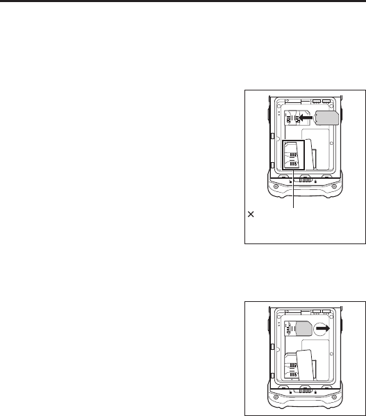
Using a SIM Card
The Smart Device supports standard SIM cards.
To use WAN functions, a SIM card must be installed.
The SIM card slot is located in the battery pack compartment, so you must remove the
battery pack before installing or removing a SIM card.
Installation
1. Turn the Smart Device off (shutdown).
2. Remove the battery pack.
(Steps 5 and 6 in the battery pack replacement
procedure on page E-16)
3. Insert the SIM card into the card slot, as shown in the
fi gure.
4. Install the battery pack.
(Steps 3-5 in the battery pack replacement procedure
on page E-15)
Removal
1. Turn the Smart Device off (shutdown).
2. Remove the battery pack.
(Steps 5 and 6 in the battery pack replacement
procedure on page E-16)
3. Pull the SIM card out of the card slot, as shown in the
fi gure.
4. Install the battery pack.
(Steps 3-5 in the battery pack replacement procedure
on page E-15)
Precautions for Use
• When installing a SIM card, check the orientation of the card and ensure that you
install it correctly. Using excessive force when installing or removing a SIM card
could damage the card.
• Touching the IC area when installing a SIM card could result in damage to the card
due to soiling or an electrostatic charge.
SAM card slot.
Do not insert the SIM card
into this slot.
E-25
Using a microSD Card
This Smart Device supports micro SD cards.
The microSD card slot is located in the battery pack compartment, so you must remove the
battery pack before installing or removing a microSD card.
Installation
1. Turn the Smart Device off (shutdown).
2. Remove the battery pack.
(Steps 5 and 6 in the battery pack replacement
procedure on page E-16)
3. Push the microSD card into the card slot until it is
fully inserted, as shown in the fi gure.
4. Install the battery pack.
(Steps 3-5 in the battery pack replacement procedure
on page E-15)
Precautions for Use
• The front and back of the card are different, so the card must be oriented correctly
when inserted into the slot. Inserting the card incorrectly could damage the card
and/or the slot. Take care when inserting cards.
Removal
1. Turn the Smart Device off (shutdown).
2. Remove the battery pack.
(Steps 5 and 6 in the battery pack replacement
procedure on page E-16)
3. Pull the microSD card out of the card slot, as shown
in the fi gure.
4. Install the battery pack.
(Steps 3-5 in the battery pack replacement procedure
on page E-15)
E-26
Handling the NFC
The NFC is a technology of contactless IC card for short range communication that enables
writing data to card and reading data from the card by applying the card close to the NFC
Reader on IT-G400.
The integrated NFC can read a contactless IC card used typically for employment
identifi cation, etc.
1. Hold the card fl at against the NFC reader on the back of the Smart Device (near the
center of the battery cover).
Important!
• If there are problems reading the card, check that the battery cover is completely
closed and try sliding the card back and forth or left and right.
• Do not apply card while it is overridden by other card. The NFC may not read it
correctly.
• A metal object near by the NFC Reader may cause the NFC not to read card
correctly. Take the card out of a wallet if the wallet is with metal object before
applying it to the NFC Reader.
• Apply card in parallel with the NFC Reader to touch the NFC Reader with the card.
• The NFC reader function in the Smart Device uses very weak radio waves that do
not require a radio station license.
• Frequency band used by the NFC is 13.56 MHz. Secure a suffi cient space between
IT-G400 and other reader/writer located in the vicinity. Make sure also that a radio
station employs the same frequency band does not locate near by prior to using
IT-G400.

E-27
Performing Communications
Bluetooth® Communication
Bluetooth® interface can also be used to transfer data between two Smart Devices.
With Bluetooth® the two Smart Devices should be located within about fi ve meters from
each other, as long as there is nothing blocking the path between them.
Important!
Observe the following precautions to help ensure that Bluetooth communication is
successful.
• Make sure two Smart Devices face each other within fi ve meters. Surroundings
(obstacles) between the Smart Devices may cause a shorter distance.
• Make sure there is at least two meters between the Smart Device and other
equipment (electrical appliances, audio-visual equipment, OA equipment, and
digital cordless telephones, facsimile machines, etc.). Take special care with
microwave ovens. Allow at least three meters between the Smart Devices in
wireless operation and a microwave oven. When operating the terminal in
Bluetooth nearby these devices and electrical appliances with their powers being
turned on, communication may be interrupted or radio receptions may be
interfered.
• Normal communication may not be possible in an area near a broadcast
trans-mitter or wireless transmitter. If this happens, move the Smart Device to a
different location. Normal communication may not be possible in areas exposed to
strong radio waves.
• Interference by WLAN
Because Bluetooth® and WLAN use the same frequency band (2.4GHz), radio
interference can occur if there is a WLAN device nearby. This can result in lower
communication speed, or even make it impossible to establish a connection. If this
happens, try the following countermeasures.
• Move at least 10 meters away from the WLAN device.
• If you cannot keep the distance at least 10 meters or more between the Smart Device
and a WLAN device, turn off the power of either the Smart Device or the WLAN
device.
• If the Smart Device’s wireless LAN and Bluetooth® communication are used at the
same time, ambient radio signals may make communication impossible.

E-28
WAN Communication
A contract with a communications provider is required in order to use the WAN communications
functions built into the Smart Device. The available WAN communications functions will be
determined by the contract between the customer and his or her communications provider.
Consult your communications provider for details of the network services.
GPS
When you use the Smart Device for the fi rst time or after an extended period of no use, it
may take a long time before the Smart Device determines its positioning. In such a case,
operate the GPS mode where there are no obstacles in the surroundings and wait for at least
15 minutes or longer.
The GPS module integrated in the Smart Device uses signals emitted by the satellites
operated by the government of the United Sates. The accuracy of positioning information
you obtain on the Smart Device may be affected by the condition of these satellites.
The GPS module may not be able to receive the signals in locations such as inside a building
or in a tunnel. If you are installing the device in your car, determine the installation location
after making sure that it can receive the signals.

E-29
Turning the Power On/Off and Sleep
Turning the Power On
1. Hold down the Power key until the Smart Device vibrates.
• The startup screen is displayed.
Precautions for Use
• Be sure to completely charge the battery pack before turning the power on for the
fi rst time after the purchase.
• If the Smart Device does not start even after power is turned on, remaining power of
the battery pack may be low. Completely charge the battery pack and then turn the
power on again.
• When the Smart Device is turned off, pressing the volume Up and Down keys while
holding down the Power key disables Smart Device startup. In this situation, hold
down the Power key until the Smart Device vibrates (around 12 seconds).
Turning the Power Off (Shutdown)
1. With the screen displayed, hold down the Power key until the Power menu is displayed.
2. Tap “Power off ”.
Sleep (Standby)
1. Press the Power key with the screen displayed.
• In the sleep state, the screen is turned off, but the Smart Device remains running.
• Operating state is maintained. Press the Power key and you will be able to use the
Smart Device immediately.
E-30
Rebooting or Resetting the Smart Device
If the Smart Device no longer operates normally due to a problem such as an operating error
or severe impact, use the procedure below to attempt to restore normal operation.
1. Reboot
2. Forced Reboot
3. Reset
Reboot
1. With the screen turned on, hold down the Power key until the Power menu is displayed.
2. Tap “Reboot”.
Forced Reboot
1. Hold down the Power key until the Smart Device vibrates (approx.12 seconds).
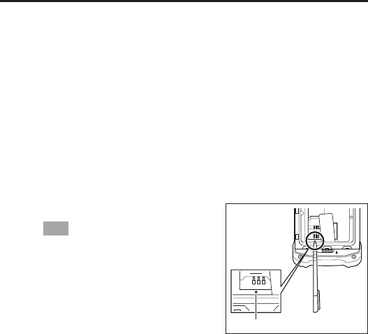
Reset
1. Open the battery cover and remove the battery
pack.
2. Hold down the Reset switch. (Approx. 2
seconds)
Tip!
Use the stylus (pen) supplied with the Smart
Device to hold down the Reset switch.
3. Re-install the battery pack and close the
battery cover.
4. Turn the power on.
Reset switch

E-31
IT-G400 Specifi cations
C21M C21L WC21M WC21L Memo
CPU ARM Cortex-A53 microprocessor (Quad core 1.2 GHz)
OS Android 6.0.1
Memory RAM: 2 GB ROM: 16 GB
Display 5.0inches 720 (horizontal) x 1280 (vertical) HD
2D imager *1 CMOS imager
Camera Rear: 8M pixels Auto Focus
Front: 2M pixels
Microphone Voice sound input
Receiver For voice call at phone network and VoIP
WLAN *2 IEEE 802.11a/b/g/n
Bluetooth *3 Specifi cation Ver.4.1+EDR/LE
WWAN *4 – LTE/W-CDMA/GSM
GPS *5 – GPS, GLONASS, BeiDou
NFC *6 Supported Cards : ISO1443 TypeA,
ISO1443 TypeB, ISO15693, Felica
microSD Compatible with SDHC
USB USB 2.0 OTG
SIM ISO7816 IC Card standard
Mini SIM Card (25 mm x 15 mm x 0.76)
Earphone and
microphone Jack CTIA standard
Main Battery
Lithium-ion
battery pack
(Standard)
Lithium-ion
battery pack
(Large)
Lithium-ion
battery pack
(Standard)
Lithium-ion
battery pack
(Large)
Sub battery Lithium battery (rechargeable)
Operating period *7 Standard Battery: 12 hours
Large Battery: 24 hours
At room
temperature
New battery
pack
Operating
temperature –20 ºC ~ 50 ºC *8
Operating Humidity 10% ~ 90%RH
Drop durability 1.5m *9
Dust /
water-resistance IP67 level

E-32
C21M C21L WC21M WC21L Memo
External dimensions
Approx. 80 mm ×
155 mm × 19 mm
(excluding
protruding parts)
Approx. 80 mm ×
155 mm × 23 mm
(excluding
protruding parts)
Approx. 80 mm ×
155 mm × 19 mm
(excluding
protruding parts)
Approx. 80 mm ×
155 mm × 23 mm
(excluding
protruding parts)
Weight Approx. 285 g Approx. 325 g Approx. 285 g Approx. 325 g
Vibrator notifi cation of scanner
Sensors Proximity sensor / Light Ambient sensor /
Acceleration sensor / Gyroscope-sensor
RTC Maximum monthly rate : 2min10sec (Use main battery)
Maximum monthly rate : 8min38sec (Use sub batery only)
*1
2D imager Spefi cications
Item Specifi cation Memo
2D imager Sensor CMOS, 832 x 640, monochrome
Aimer laser (λ = 650 nm), < 1 mW < Class 2 Laser
Scan Angle 0 °
Minimum
Resolution
1D: 0.127 mm
2D Stacked: 0.168 mm
2D Matrix: 0.191 mm
PCS ≥ 0.45
Depth of Field
1D: 50 mm ~ 400 mm
2D Stacked: 50 mm ~ 230 mm
2D Matrix: 70 mm ~ 300 mm
Field of View Max 43 mm (Depth of Field 50 mm)
Max 277 mm (Depth of Field 400 mm)
Focal Distance 5.0 inch
Ambient Light Sunlight, ≤ 50,000Lux
Readable
Symbologies
(1D)
UPC-A/UPC-E/EAN8 (JAN8)/EAN13 (JAN13)/
Codabar (NW-7)/Code39/Interleaved2of5 (ITF)/MSI/
ISBT/Code93/Code128 (GS1-128 (EAN128))/
GS1 DataBarOmnidirectional (RSS-14)/
GS1 DataBarLimited (RSS Limited)/
GS1 DataBar Expanded (RSS Expanded)/
GS1 DataBar Truncated / Code32
Readable
Symbologies
(2D Stacked)
PDF417/Micro PDF/Composite/Codablock F/
GS1 DataBar Stacked Omnidirectional (RSS-14 Stacked)/
GS1 DataBar Expanded Stacked (RSS Expanted Stacked)/
GS1 DataBar Stacked (RSS-14 Stacked)
Readable
Symbologies
(2D Matrix)
Aztec/DataMatrix/Maxicode/QR Code/Micro QR/HanXin
E-33
*2
WLAN Spefi cications
Item Specifi cation Memo
WLAN
802.11a/b/
g/n Frequency
Range
2412 MHz – 2472 MHz (1 ~ 13ch)
5180 MHz – 5320 MHz (36 ~ 64ch)
5500 MHz – 5700 MHz (100 ~ 140ch)
5745 MHz – 5825 MHz (149 ~ 165ch)
(802.11d: Allowed frequency range can be used according
to countries or regions.)
Baud rate
802.11a/g: 54 Mbps (maximum)
802.11b: 11 Mbps (maximum)
802.11n HT20 (2.4&5 GHz): 72 Mbps (maximum)
Communication
Distance
Communication Distance 802.11b/g/n: Indoor 50m,
Outdoor 150 m (n: 2.4 GHz)
802.11a/n: Indoor 30m, Outdoor 150 m (n: 5 GHz)
It can change
due to
surrounding
environment
*3
Bluetooth Spefi cications
Item Specifi cation Memo
Bluetooth Frequency
Range 2402 MHz – 2480 MHz
Communication
Distance
about 5m
It can change
due to
surrounding
environment
*4
WWAN Spefi cications
Item Specifi cation Memo
LTE
Communication
Data Packet
Baud rate Downlink (150 Mbps (maximum)
Uplink (50 Mbps (maximum)
Frequency
range Band
FDD 1 (1920-1980 MHz/2110-2170 MHz)
FDD 2 (1850-1910 MHz/1930-1990 MHz)
FDD 3 (1710-1785 MHz/1805-1880 MHz)
FDD 4 (1710-1755 MHz/2110-2155 MHz)
FDD 5 (824-849 MHz/869-894 MHz)
FDD 7 (2500-2570 MHz/2620-2690 MHz)
FDD 8 (880-915 MHz/925-960 MHz)
FDD 17 (704-716 MHz/734-746 MHz)
FDD 20 (832-862 MHz/791-821 MHz)
TDD 40 (2300-2400 MHz/2300-2400 MHz)
TDD 41 (2496-2690 MHz/2496-2690 MHz)
E-34
Item Specifi cation Memo
W-CDMA
Communication
Audio, Data Packet
Baud rate Downlink (42 Mbps (maximum)
Uplink (11 Mbps (maximum)
Protocol UMTS/HSDPA/HSUPA
Frequency
range Band
BAND 1 (1920-1980 MHz/2110-2170 MHz)
BAND 2 (1850-1910 MHz/1930-1990 MHz)
BAND 5 (824-849 MHz/869-894 MHz)
BAND 6 (830 - 840 MHz/875 - 885 MHz)
BAND 8 (880-915 MHz/925-960 MHz)
BAND 19 (830-845 MHz/875-890 MHz)
GSM
Communication
Audio, Data Packet
Protocol GSM/GPRS/EDGE
Frequency
range Band
EGSM900 (880-915 MHz/925-960 MHz)
DCS1800 (1710-1785 MHz/1805-1880 MHz)
*5
GPS Spefi cications
Item Specifi cation Memo
GPS WAN and
GNSS modes
Simultaneous-GNSS (WAN+GNSS at the same time)
Standalone-GNSS (without WAN)
A-GPS
Protocol
NMEA
Sensitivity
Acquisition sensitivity: -145 dBm
Tracking sensitivity: -158 dBm
*6
NFC Spefi cications
Item Specifi cation Memo
NFC
Depth of Field
ISO14443 Type A/B, Felica:
0 mm (Contact)
It can change
by the design
of Card or
Tag
ISO15693:
0 mm (Contact) ~ 50 mm (Maximum)

E-35
*7
According to JEITA G mode
LCD backlight brightness minimum, WLAN ON (with stable RF connection), Buzzer minimum, Vibrator
OFF, RF OFF (except for WLAN), Power saving setting after laser scanning (1sec)
*8
• Camera Flash is unavailable in –20 ºC ~ –11 ºC.
• Battery pack charge operation: 0 ~ 50 ºC
For the temperature of 0 ~ 10 ºC and 40 ~ 50 ºC, in order to protect battery cell, charge control changes.
Therefore in these temperature environment, battery indicator might not become 100% after the charge ends
and charge status LED turns green. Charging stops if the battery pack’s internal temperature is 0 °C or below
or 50 °C or above.
*9
The drop durability height is a measured value resulting from actual testing. It does not necessarily guarantee
the product from damage
E-36
Installing and Removing the AC Adapter for the USB and LAN Cradles
The AC adapter for the USB and LAN cradles must be fi tted with a suitable power plug for
the region where the Smart Device will be used.
Installation
1. Insert the protruding part of the AC adapter
plug into the recess in the top of the AC
adapter ( ) until the plug clicks into place
().
Removat
1. Push the AC adapter plug release lever in the
direction indicated by the arrow in the fi gure
() and then pull out the AC adapter plug in
the direction of the arrow ( ).
Precautions for Use
• Do not insert the plug only into the power outlet.
Arrow pointing
downwards
E-37
USB Cradle (HA-R60IO)
The USB cradle can be used to connect the IT-G400 to devices such as a computer or USB
device. It can also be used to supply power to the IT-G400 and to charge the battery pack.
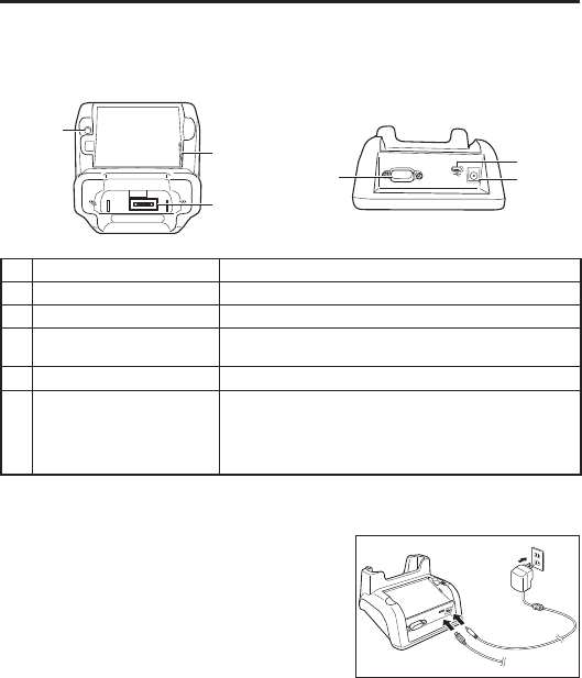
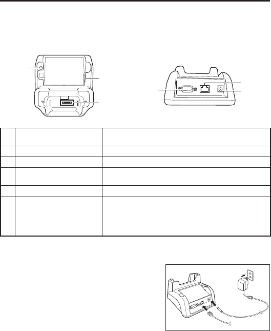
Part Names and Operation
<Top> <Back>
4
6
51
3
2
1 USB port Used to connect to a computer or USB device.
2 Serial port The cradle features a serial port, but it cannot be used.
3 AC adapter jack Used to connect an AC adapter as a power supply.
4Power supply/
data communication terminal Used to supply power to the IT-G400 or for data communication.
5 Battery pack power contacts Used to charge the battery pack.
6Battery pack charging status
LED
Shows the charging status.
Red: Charging
Green: Charging complete
Flashing alternately red/green: Battery pack fault or outside
charging temperature range
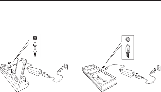
Installing and Connecting the Power Supply
Use the supplied AC adapter as the power supply for the USB cradle.
1. Plug the AC adapter into the AC adapter jack
on the back of the USB cradle.
2. Plug the AC adapter into a mains power outlet.
3. When connecting to a computer, plug the
micro USB cable provided into the USB port.
When connecting to a USB device, plug the
USB host cable into the USB port. Computer
E-38
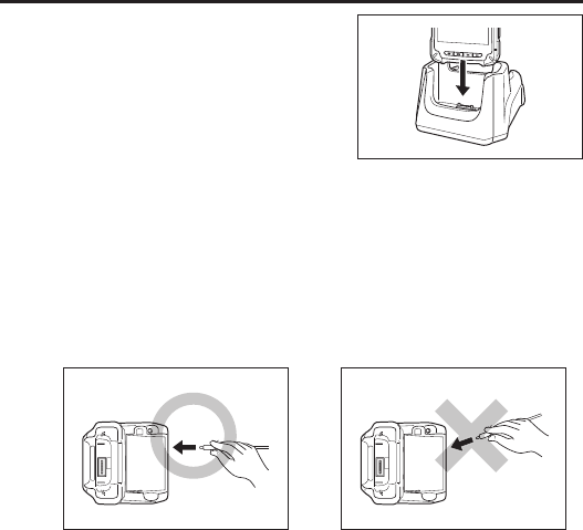
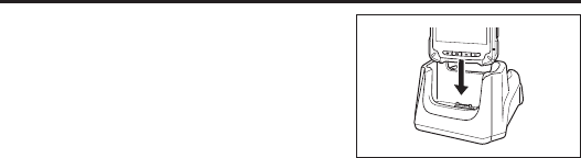
4. Align the terminals on the base of the IT-G400
with the power contacts in the USB cradle and
then set the IT-G400 in the cradle.
Precautions for Use
• Even if the battery in the IT-G400 is already fully charged, charging will begin when
you set the IT-G400 in the USB cradle. It may take several minutes for the fully
charged status to be indicated.
• In high- or low-temperature environments, charging may be restricted to protect the
battery pack. At such temperatures, the level of battery charge may not reach 100%
even when the charging status LED is green and charging is completed.
• When connecting a micro USB cable, push the plug fi rmly all the way into the socket.
• When connecting or disconnecting a micro USB cable, take care to keep the plug
straight relative to the USB port. Avoid pushing or pulling the micro USB cable at an
angle and do not pull on or twist the cord when the micro USB cable is connected.
Doing so could distort the micro USB cable connectors.
Correct
Straight
Incorrect
Angled
• When the IT-G400 is connected to a computer using the USB cradle, the USB cradle
must always be used with the bundled AC adapter connected. Failing to connect the
AC adapter may result in unstable USB communication.
• Water or other moisture on the power contacts could cause sparking or an electric
shock, and soiled contacts could block the connection and impair charging
functionality. To ensure safety, clean the power contacts by wiping them off with a
dry cloth or cotton bud after you disconnect the AC adapter.
• When disconnecting the AC adapter from the mains power outlet and IT-G400, do so
by gripping the connector and not by pulling on the cord.

E-39
USB Cradle (HA-R60IO) Specifi cations
1. USB specifi cations
Standard: USB 2.0 High Speed
Transmission speed: 480 Mbps (max.)
2. Charging specifi cations
Charging method: Constant-voltage constant-current charging
Charging time: Approx. 4 hours (standard battery pack)
Approx. 8 hours (high-capacity battery pack)
3. AC adapter specifi cations
Standard: ADS-25SGP-06
Input: 100-240 V AC, 50/60 Hz, 0.7 A
Output: 5 V DC, 4 A
4. Dimensions, weight
Dimensions: Approx. 136 × 116 × 81 mm (W x D x H)
Weight: Approx 315 g
5. Operating environment
Operating temperature: 0°C to 40°C
Operating humidity: 10-90% RH (condensation-free)
E-40
LAN Cradle (HA-R62IO)
The LAN Cradle allows a LAN interface to be used to transfer data between the IT-G400
and a personal computer. It can also be used to supply power to the IT-G400 and to charge
the battery pack.
Part Names and Operation
<Top> <Back>
4
6
51
3
2
1 LAN port Used to connect and transfer data to a personal computer or hub
via a LAN cable for data transfer.
2 Serial port The cradle features a serial port, but it cannot be used.
3 AC adapter jack Used to connect an AC adapter as a power supply.
4Power supply/
data communication terminal Used to supply power to the IT-G400 or for data communication.
5 Battery pack power contacts Used to charge the battery pack.
6Battery pack charging status
LED
Shows the charging status.
Red: Charging
Green: Charging complete
Flashing alternately red/green: Battery pack fault or outside
charging temperature range
Installing and Connecting the Power Supply
Use the supplied AC adapter as the power supply for the LAN cradle.
1. Plug the AC adapter into the AC adapter jack
on the back of the LAN cradle.
2. Plug the AC adapter into a mains power outlet.
3. When using a LAN, plug the LAN cable into
the LAN port and then connect the cable to the
computer or to a hub.
Computer
E-41
4. Align the terminals on the base of the IT-G400
with the power contacts in the LAN cradle and
then set the IT-G400 in the cradle.
Precautions for Use
• Even if the battery in the IT-G400 is already fully charged, charging will begin when
you set the IT-G400 in the LAN cradle. It may take several minutes for the fully
charged status to be indicated.
• In high- or low-temperature environments, charging may be restricted to protect the
battery pack. At such temperatures, the level of battery charge may not reach 100%
even when the charging status LED is green and charging is completed.
• Water or other moisture on the power contacts could cause sparking or an electric
shock, and soiled contacts could block the connection and impair charging
functionality. To ensure safety, clean the power contacts by wiping them off with a
dry cloth or cotton bud after you disconnect the AC adapter.
• When disconnecting the AC adapter from the mains power outlet and IT-G400, do so
by gripping the connector and not by pulling on the cord.

E-42
LAN Cradle (HA-R62IO) Specifi cations
1. LAN specifi cations
Communications method: IEEE 802.3-compliant
Media type: 10base-T/100base-TX auto switched
2. Charging specifi cations
Charging method: Constant-voltage constant-current charging
Charging time: Approx. 4 hours (standard battery pack)
Approx. 8 hours (high-capacity battery pack)
3. AC adapter specifi cations
Standard: ADS-25SGP-06
Input: 100-240 V AC, 50/60 Hz, 0.7 A
Output: 5 V DC, 4 A
4. Dimensions, weight
Dimensions: Approx. 136 × 116 × 81 mm (W x D x H)
Weight: Approx 330 g
5. Operating environment
Operating temperature: 0°C to 40°C
Operating humidity: 10-90% RH (condensation-free)
E-43
Four-cradle Battery Charger (HA-R38CHG)
The Four-cradle Battery Charger enables you to charge four IT-G400 terminals at the same
time.
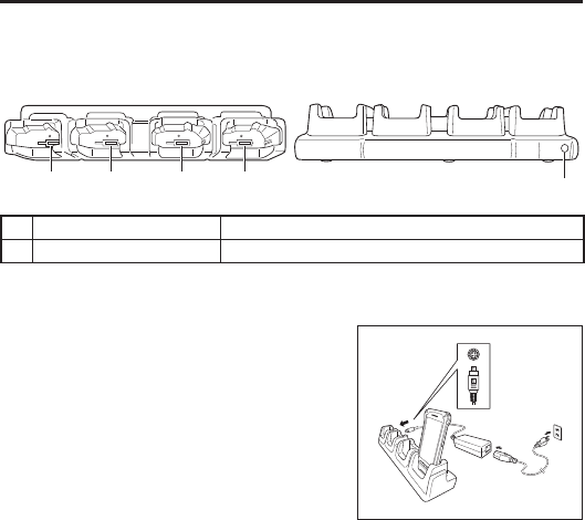
Part Names and Operation
<Top> <Back>
11 1 1 2
1 Power contacts Used to supply power to the IT-G400.
2 AC adapter jack Used to connect an AC adapter as a power supply.
Installing and Connecting the Power Supply
Use the dedicated AC adapter as the power supply for the Four-cradle Battery Charger.
1. Plug the AC adapter connector into the AC
adapter jack on the Four-cradle Battery
Charger.
2. Plug the optional AC cable plug into a mains
power outlet.
3. Align the terminals on the base of the IT-G400
with the power contacts in the Four-cradle
Battery Charger and then set the IT-G400
unit(s) in the Four-cradle Battery Charger.
Precautions for Use
• Even if the battery in the IT-G400 is already fully charged, charging will begin when
you set the IT-G400 in the Four-cradle Battery Charger. It may take several minutes
for the fully charged status to be indicated.
• Water or other moisture on the power contacts could cause sparking or an electric
shock, and soiled contacts could block the connection and impair charging
functionality. To ensure safety, clean the power contacts by wiping them off with a
dry cloth or cotton bud after you disconnect the AC adapter.
• Do not disconnect the AC adapter while an IT-G400 is still set in the charger.
• When disconnecting the AC adapter from the mains power outlet and IT-G400, do so
by gripping the connector and not by pulling on the cord.
AC adapter
(12 V, 5 A)

E-44
Four-cradle Battery Charger (HA-R38CHG) Specifi cations
1. Charging specifi cations
Charging method: Constant-voltage constant-current charging
Charging time: Approx. 4 hours (standard battery pack)
Approx. 8 hours (high-capacity battery pack)
2. AC adapter specifi cations
Standard: CGSW-1205000
Input: 100-240 V AC, 50/60 Hz, 1.5A
Output: 12 V DC, 5 A
3. Dimensions, weight
Dimensions: Approx. 450 × 100 × 90 mm (W x D x H)
Weight: Approx 800 g
4. Operating environment
Operating temperature: 0°C to 40°C
Operating humidity: 10-90% RH (condensation-free)
E-45
Four-bay Battery Charger (HA-R34CHG)
The Four-bay Battery Charger enables you to charge four battery packs at the same time.
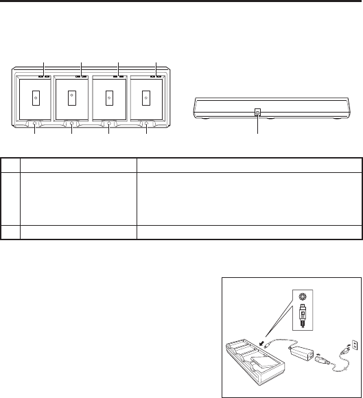
Part Names and Operation
<Top> <Back>
1111
2222 3
1 Charging contacts Used to charge the battery pack.
2 Charging status LED
Shows the charging status.
Red: Charging
Green: Charging complete
Flashing alternately red/green: Battery pack fault or outside
charging temperature range
3 AC adapter jack Used to connect an AC adapter as a power supply.
Installing and Connecting the Power Supply
Use the dedicated AC adapter as the power supply for the Four-bay Battery Charger.
1. Plug the AC adapter connector into the AC
adapter jack on the Four-bay Battery Charger.
2. Plug the optional AC cable plug into a mains
power outlet.
3. Install the battery pack(s) in the Four-bay
Battery Charger, taking care that the battery
pack terminals are oriented correctly.
Charging Status LED Display
Red: Charging
Green: Charging complete
Flashing alternately red/green: Battery pack fault or outside charging temperature range
AC adapter
(12 V, 5 A)

E-46
Precautions for Use
• Even if the battery packs are already fully charged, charging will begin when you set
the battery packs in the Four-bay Battery Charger. It may take several minutes for
the fully charged status to be indicated.
• Water or other moisture on the charging terminals could cause sparking or an
electric shock, and soiled terminals could block the connection and impair charging
functionality. To ensure safety, clean the power contacts by wiping them off with a
dry cloth or cotton bud after you disconnect the AC adapter.
• The battery packs may become warm during charging. This is normal and does not
indicate a fault.
• Do not cover or place objects on top of the battery charger during charging.
• When disconnecting the AC adapter from the mains power outlet and IT-G400, do so
by gripping the connector and not by pulling on the cord.
Four-bay Battery Charger (HA-R34CHG) Specifi cations
1. Charging specifi cations
Charging method: Constant-voltage constant-current charging
Charging time: Approx. 4 hours (standard battery pack)
Approx. 8 hours (high-capacity battery pack)
2. AC adapter specifi cations
Standard: CGSW-1205000
Input: 100-240 V AC, 50/60 Hz, 1.5A
Output: 12 V DC, 5 A
3. Dimensions, weight
Dimensions: Approx. 256 × 105 × 37 mm (W x D x H)
Weight: Approx 435 g
4. Operating environment
Operating temperature: 0°C to 40°C
Operating humidity: 20-90% RH (condensation-free)
E-47
USB Cable (HA-R81USBC)
The USB cable can be used to connect the IT-G400 to a computer. It can also be used to
supply power to the IT-G400.
Installing and Connecting the Power Supply
To use the USB cable, use the AC adapter supplied with the IT-G400.
1. Plug the AC adapter into the AC adapter jack
on the USB cable.
2. Plug the AC adapter into a mains power outlet.
3. Align the terminals on the base of the IT-G400
with the USB cable terminals and then connect
the USB cable to the IT-G400.
4. When connecting to a computer, connect via
the USB port.
Precautions for Use
• The USB cable can only be connected one way. Do not attempt to plug the USB cable
in the wrong way by using excessive force.
• Water or other moisture on the IT-G400 and USB cable power supply/data
communication terminal could cause sparking or an electric shock, and soiling on
the terminal could block the connection and impair charging functionality. To ensure
safety, disconnect the AC adapter and USB cable and then clean the power contacts
by wiping them off with a dry cloth or cotton bud.
• Never short-circuit the IT-G400 and the USB cable power supply/data
communication terminal as this could cause a fault.
• When connecting the USB cable, always ensure that the dedicated AC adapter for
the IT-G400 (AD-S10050B) is also connected to the USB cable. Failing to connect the
AC adapter may result in unstable USB communication.
Computer
E-48
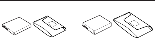
Using Rechargeable Battery Packs
HA-R20BAT HA-R21LBAT
You can choose between two battery packs with different capacities for the Smart Device,
depending on how long it will be used and the operating environment.
Important!
• Store a battery pack in its special soft case whenever you are not using it.
• If the battery pack has been left over unused for a long period of time, the capacity
remained decreases due to spontaneous discharge or chemical decomposition by the
battery pack itself. If the battery pack fails to hold its operating duration after it has
been fully charged, replace it with a new one. The battery pack may reach the end of
its service life.
Battery Pack Specifi cations
Model: HA-R20BAT
Rated Capacity: 2900mAh (11.2 Wh)
Rated Voltage: 3.85V
Dimensions: Approximately 57.5(W) × 76(D) × 6.9(H) mm
Weight: Approximately 54g
Bundled Item: Soft case
Large-capacity Battery Pack Specifi cations
Model: HA-R21LBAT
Rated Capacity: 5800mAh (22.4Wh)
Rated Voltage: 3.85V
Dimensions: Approximately 57.5(W) × 76(D) × 11(H) mm
Weight: Approximately 98g
Bundled Item: Soft case

CASIO COMPUTER CO., LTD.
6-2, Hon-machi 1-chome
Shibuya-ku, Tokyo 151-8543, Japan
PN410522-002
MO1804-B
2017 CASIO COMPUTER CO., LTD.
