CastleNet Technology CBV3843Z4S Wireless Cable Modem Gateway User Manual CBV3843Z4S AC1600 User s Manual
CastleNet Technology Inc. Wireless Cable Modem Gateway CBV3843Z4S AC1600 User s Manual
UserManual.wiki
>
CastleNet Technology
>
CBV3843Z4S User Manual
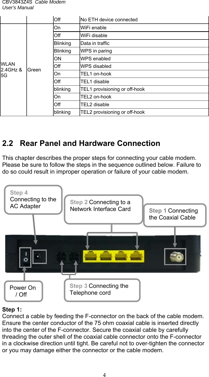
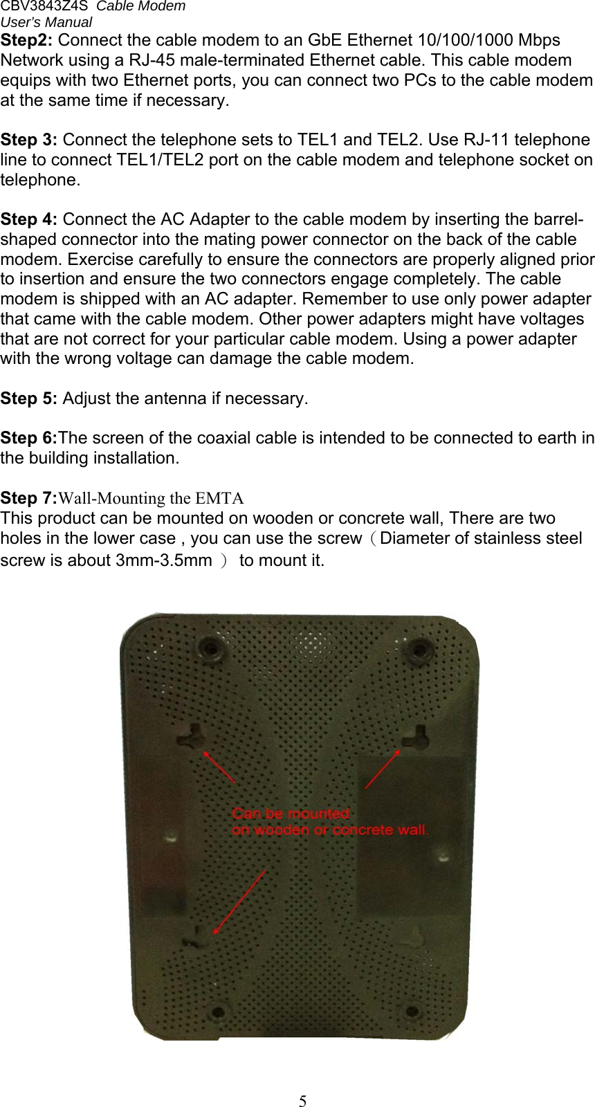
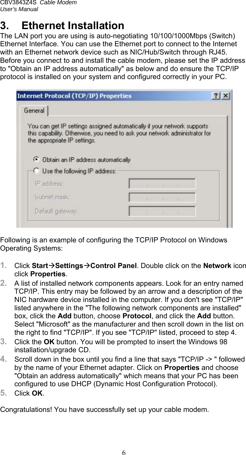
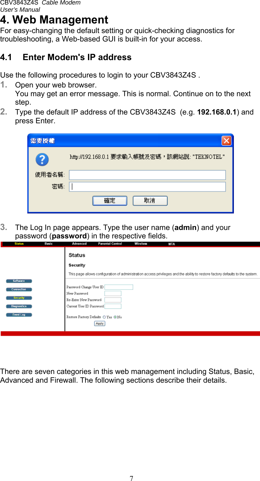
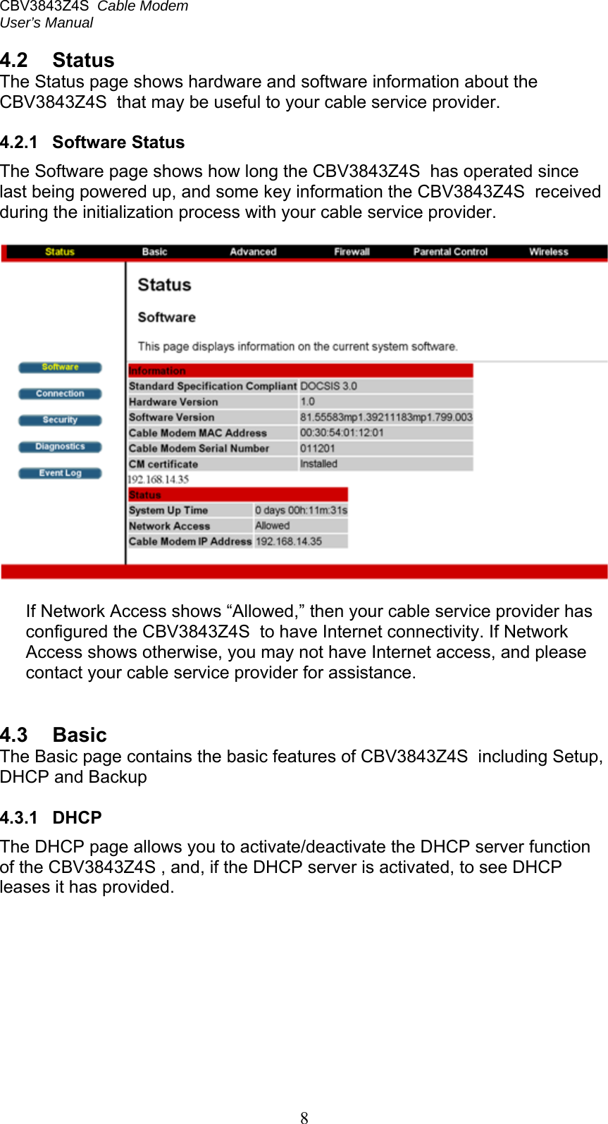
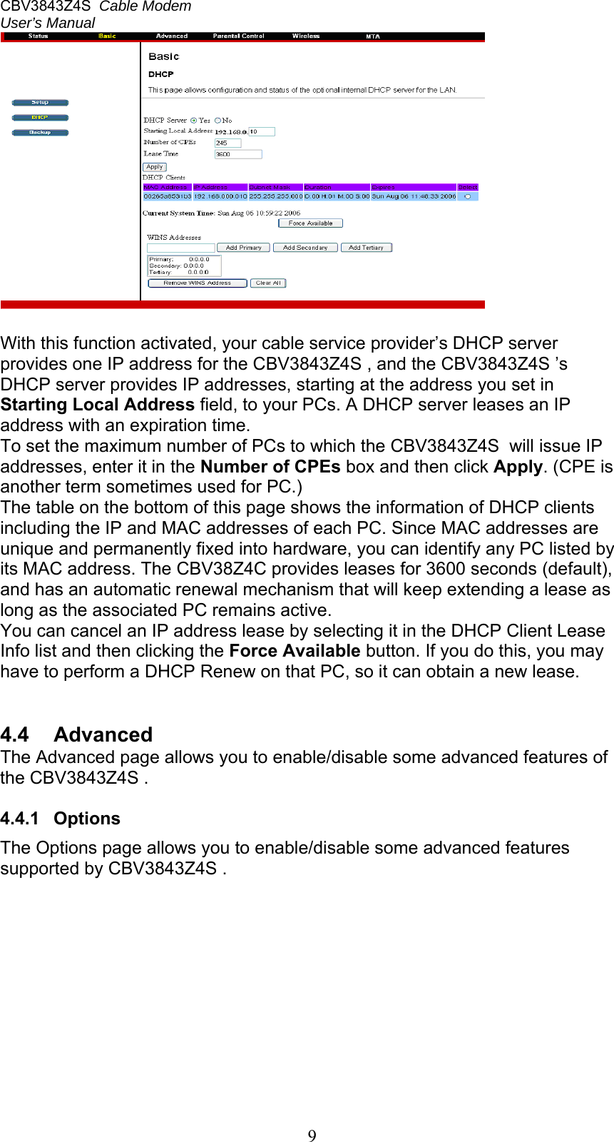
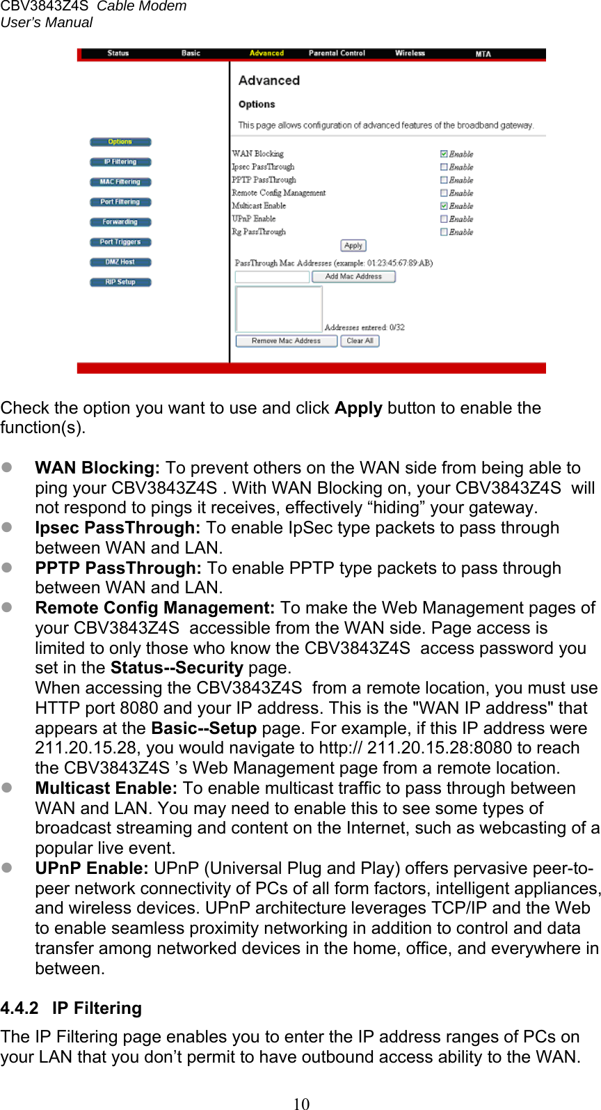
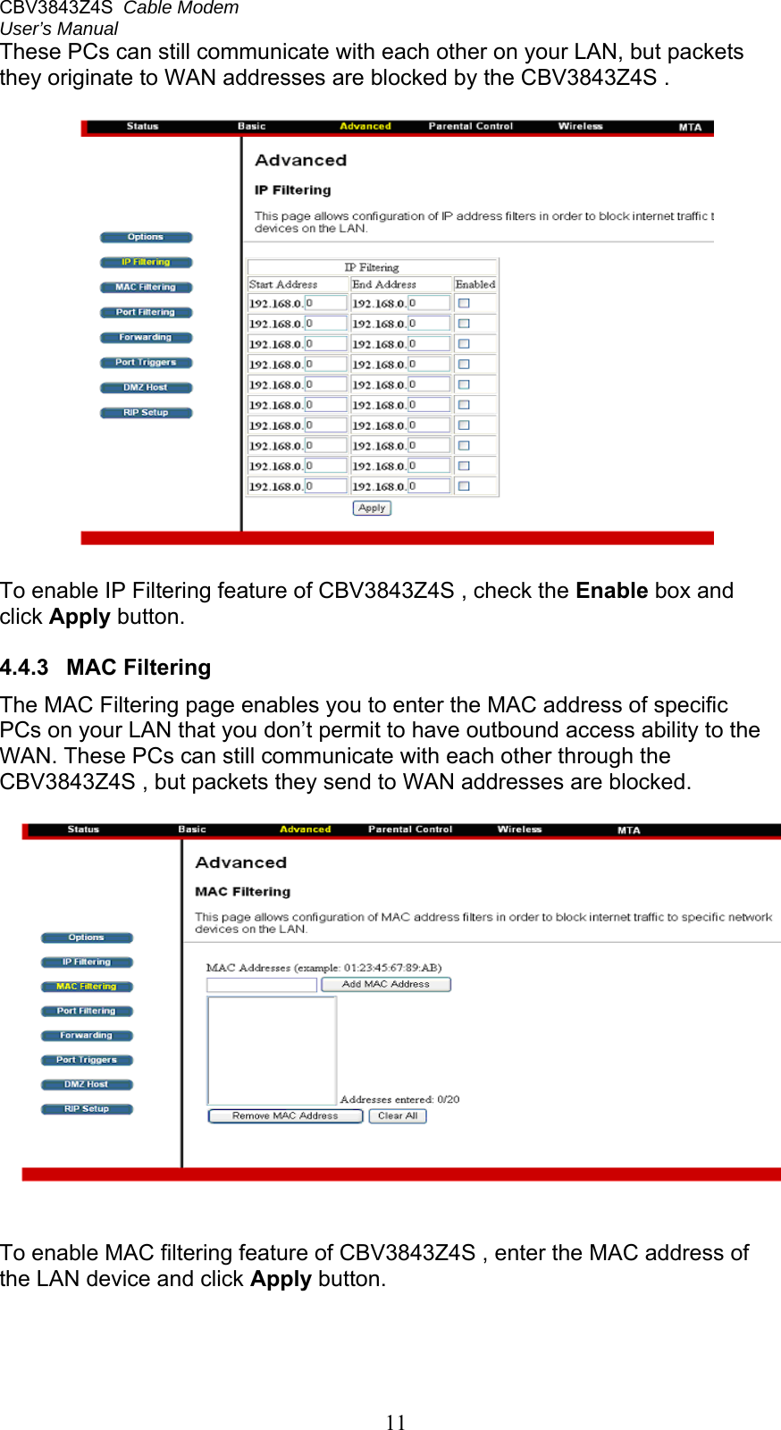
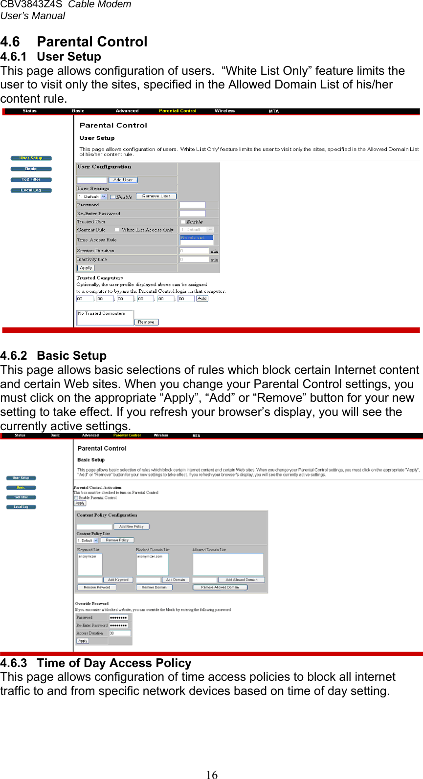
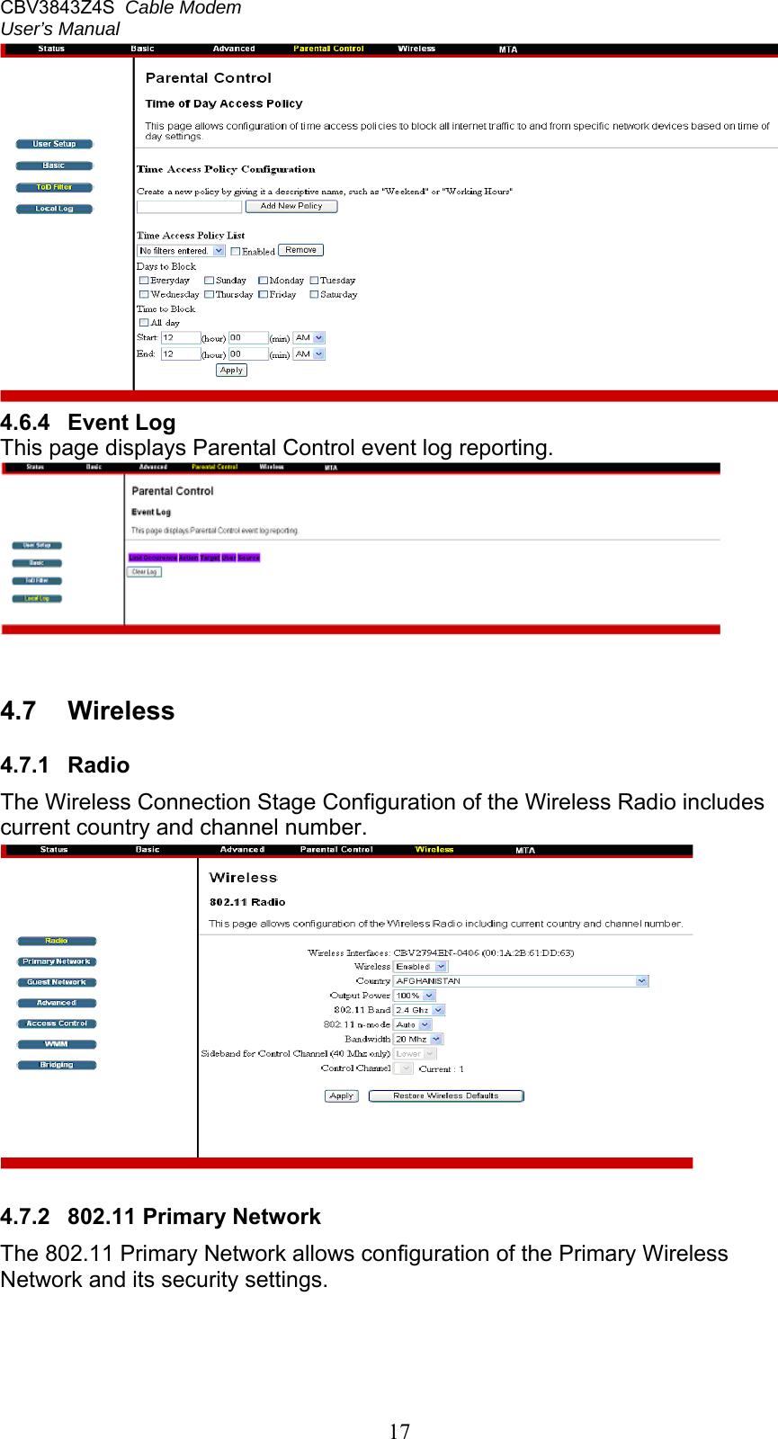
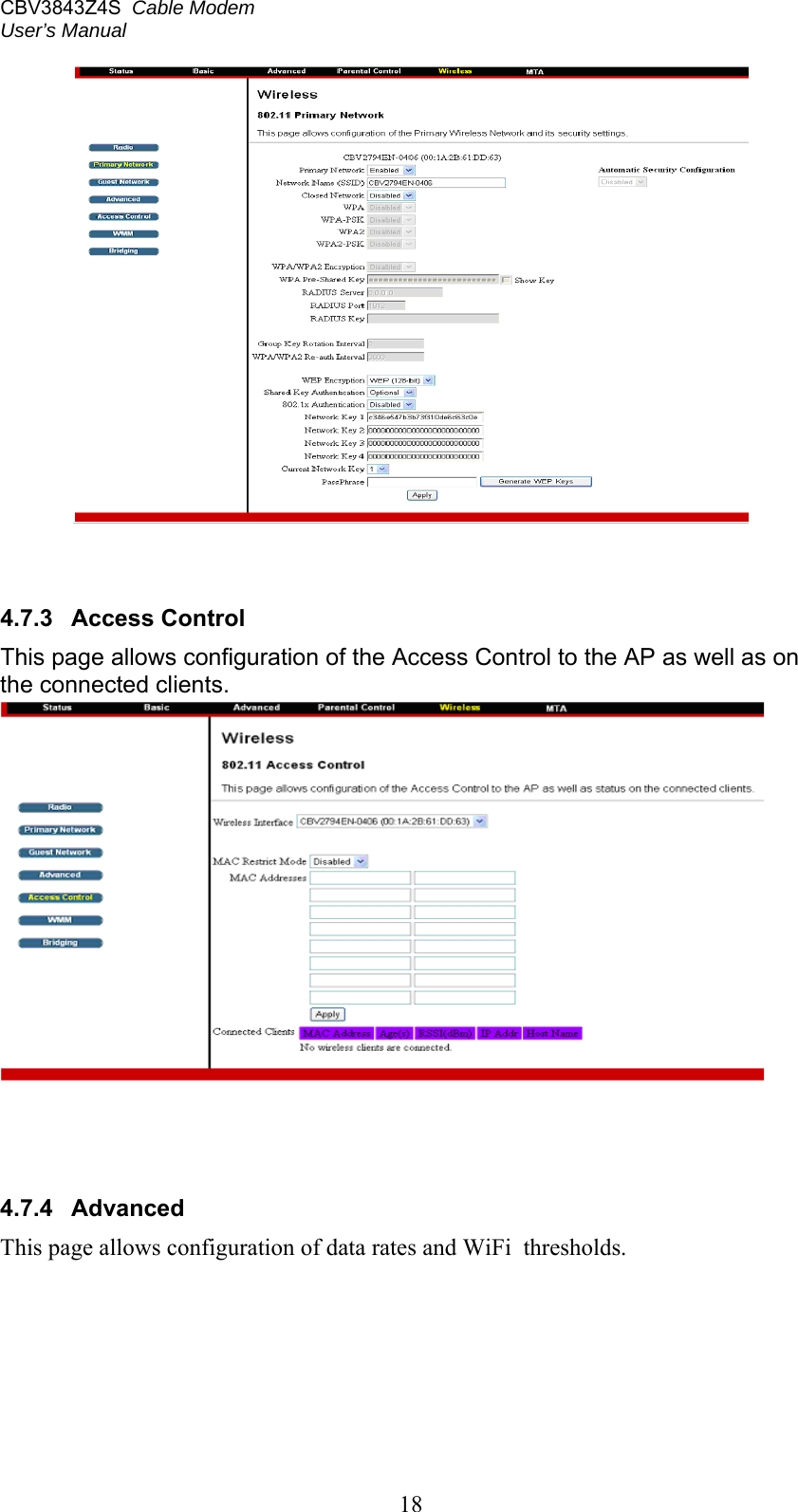
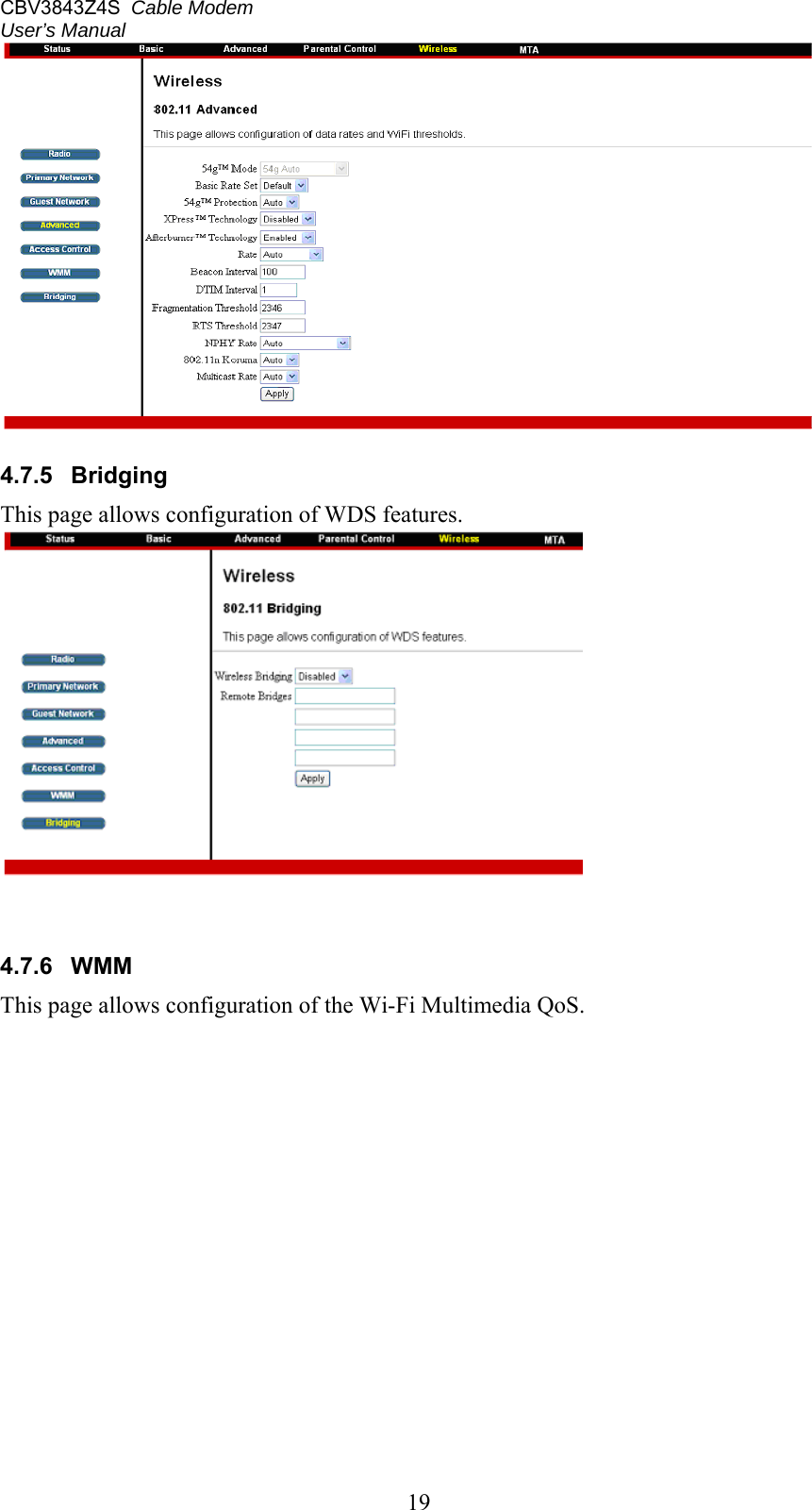
Users Manual
Navigation menu
Upload a User Manual
Namespaces
Wiki Guide
HTML
PDF
Info
Views
User Manual
Discussion / Help
Navigation