CastleNet Technology CBV704W 802.11 b/g Wireless Router User Manual
CastleNet Technology Inc. 802.11 b/g Wireless Router
user manual

Revision 1.0
Jan 2008
C
CB
BV
V7
70
04
4E
EW
W
S
Se
er
ri
ie
es
s
P
Pa
ac
ck
ke
et
tC
Ca
ab
bl
le
e
1
1.
.5
5
a
an
nd
d
D
DO
OC
CS
SI
IS
S/
/E
EU
UR
RO
OD
DO
OC
CS
SI
IS
S
2
2.
.0
0
C
Co
om
mp
pl
li
ia
an
nt
t
4
4
P
Po
or
rt
ts
s
E
Et
th
he
er
rn
ne
et
t
C
Ca
ab
bl
le
e
M
Mo
od
de
em
m
w
wi
it
th
h
W
Wi
ir
re
el
le
es
ss
s
a
an
nd
d
E
EM
MT
TA
A
U
Us
se
er
r’
’s
s
M
Ma
an
nu
ua
al
l

Federal Communication Commission Interference Statement
This equipment has been tested and found to comply with the limits for a
Class B digital device, pursuant to Part 15 of the FCC Rules. These limits are
designed to provide reasonable protection against harmful interference in a
residential installation. This equipment generates, uses and can radiate radio
frequency energy and, if not installed and used in accordance with the
instructions, may cause harmful interference to radio communications.
However, there is no guarantee that interference will not occur in a particular
installation. If this equipment does cause harmful interference to radio or
television reception, which can be determined by turning the equipment off
and on, the user is encouraged to try to correct the interference by one of the
following measures:
- Reorient or relocate the receiving antenna.
- Increase the separation between the equipment and receiver.
- Connect the equipment into an outlet on a circuit different from that to which
the receiver is connected.
- Consult the dealer or an experienced radio/TV technician for help.
This device complies with Part 15 of the FCC Rules. Operation is subject to
the following two conditions:
(1) This device may not cause harmful interference, and
(2) This device must accept any interference received, including interference
that may cause undesired operation.
Information to User
To assure continued compliance, (example - use only shielded interface
cables when connecting to computer or peripheral devices) any changes or
modifications not expressly approved by the party responsible for compliance
could void the user’s authority to operate this equipment.
Only Coaxial cables are to be used with this device in order to ensure
compliance with FCC emissions limits. Accessories connected to this device
by the user must comply with FCC Class B limits. The manufacturer is not
responsible for any interference which results from use of improper cables, or
which results from unauthorized changes or modifications to the device.
"A Minimum 26 AWG Line Core should be used for connection to the cable
modem"
IMPORTANT NOTE:
FCC Radiation Exposure Statement:
This equipment complies with FCC radiation exposure limits set forth for an
uncontrolled environment. This equipment should be installed and
operated with minimum distance 20cm between the radiator & your body.
This transmitter must not be co-located or operating in conjunction with any
other antenna or transmitter.
FEDERAL COMMUNICATIONS COMMISSION
This device complies with Part 15 of the FCC Rules.
Operation is subject to the following two conditions :(1) this
device may not cause harmful interference, and (2) this
device must accept any interference received, including
interference that may cause undesired operation.
CBV704EW Series Cable Modem
User’s Manual
iii
Warranty
Items sold by manufacturer/distributor/agent, hereinafter called "Seller", are
warranted only as follows: Except as noted below Seller will correct, either by
repair or replacement at its option, any defect of material or workmanship
which develops within one year after delivery of the item to the original Buyer
provided that evaluation and inspection by Seller discloses that such defect
developed under normal and proper use. Repaired or replaced items will be
further warranted for the unexpired term of their original warranty. All items
claimed defective must be returned to Seller, transportation charges prepaid,
and will be returned to the Buyer with transportation charges collect unless
evaluation proves the item to be defective and that the Seller is responsible
for the defect. In that case, Seller will return to Buyer with transportation
charge prepaid. Seller may elect to evaluate and repair defective items at the
Buyer's site. Seller may charge Buyer a fee (including travel expenses, if
needed) to cover the cost of evaluation if the evaluation shows that the items
are not defective or that they are defective for reasons beyond the scope of
this warranty.
The Seller makes no warranty concerning components or accessories not
manufactured by it. However, in the event of failure of such a part, Seller will
give reasonable assistance to Buyer in obtaining from the manufacturer
whatever adjustment is reasonable in light of the manufacturer's own warranty.
Seller will not assume expense or liability for repairs made outside the factory
by other than Seller's employees without Seller's written consent.
SELLER IS NOT RESPONSIBLE FOR DAMAGE TO ANY ASSOCIATED
EQUIPMENT, NOR WILL SELLER BE HELD LIABLE FOR INCIDENTAL,
CONSEQUENTIAL, OR OTHER DAMAGES. THIS WARRANTY IS IN LIEU
OF ALL OTHER WARRANTIES EXPRESSED OR IMPLIED INCLUDING
THE IMPLIED WARRANTY OF "MERCHANTABILITY" AND "FITNESS FOR
PARTICULAR PURPOSE."
Trademarks
All trademarks are the property of their respective owners.
Table of Contents
FEDERAL COMMUNICATION COMMISSION INTERFERENCE
STATEMENT .............................................................................................................II
INFORMATION TO USER...............................................................................................II
1. INTRODUCTION................................................................................................1
FEATURES ...................................................................................................................1
SYSTEM REQUIREMENTS.............................................................................................1
UNPACKING AND INSPECTION .....................................................................................2
SAFETY PRECAUTIONS ................................................................................................2
2. HARDWARE OVERVIEW................................................................................3
FRONT PANEL AND LEDS...........................................................................................3
3. ETHERNET INSTALLATION..........................................................................6
4. USB DRIVER INSTALLATION .......................................................................7
WINDOWS XP.............................................................................................................7
WINDOWS 2003 ..........................................................................................................9
WINDOWS VISTA ......................................................................................................11
5. WEB MANAGEMENT.....................................................................................13
ENTER MODEM'S IP ADDRESS ...................................................................................13
STATUS .....................................................................................................................14
5.1.1 Software Status.....................................................................................14
BASIC........................................................................................................................14
5.1.2 DHCP...................................................................................................15
ADVANCED ...............................................................................................................15
5.1.3 Options.................................................................................................16
5.1.4 IP Filtering...........................................................................................16
5.1.5 MAC Filtering......................................................................................17
5.1.6 Port Filtering .......................................................................................17
5.1.7 Forwarding ..........................................................................................18
5.1.8 Port Triggers........................................................................................19
5.1.9 DMZ Host.............................................................................................19
FIREWALL .................................................................................................................20
5.1.10 Local Log .............................................................................................20
PARENTAL CONTROL ................................................................................................21
WIRELESS .................................................................................................................23
5.1.11 Basic.....................................................................................................23
5.1.12 Security ................................................................................................23
5.1.13 Access Control .....................................................................................24
5.1.14 Advanced..............................................................................................24
5.1.15 Bridging ...............................................................................................25
5.1.16 WMM....................................................................................................25
5.1.17 Guest Network......................................................................................25
MTA.........................................................................................................................26
5.1.18 Status....................................................................................................26
APPENDIX: CABLE MODEM SPECIFICATION...............................................27
CBV704EW Series Cable Modem
User’s Manual
1
1. Introduction
The CBV704EW is a Voice over IP Wireless Residential Gateway integrated
with Cable Modem which allows you implement your VoIP phone call directly
through Cable Modem Broadband Network service with its built-in
PacketCable 1.5 and DOCSIS/EURODOCSIS 2.0 compliant specification.
Equipped with two standard phone ports, CBV704EW series could easily
provide end-users low-cost, long-distance calling, faxing, and a host of
advanced service including CBV704EW-to-Phone, Phone-to-CBV704EW, and
CBV704EW-to-CBV704EW.
And with the integration of 4 ports switch and IEEE 802.11g wireless
functionality, the CBV704EW series could also be used as a Wireless Cable
Modem Residential Gateway in your home or small office. The ability to route
data information into your broadband network could help you easily extend
your local network via wire or wireless.
The CBV704EW is MGCP/SIP compliant and has been tested with most
major VoIP Softswitch vendors’ Call Management systems. And it also has
voice support that includes hardware based Quality of Service (QoS), voice
compression (popular voice CODECs G.711, G.729A, G.723.1, and so on),
echo cancellation, dynamic latency (jitter) buffers, silence suppression, and
comfort noise generator.
Features
z PacketCable 1.5 standard compliant
z DOCSIS /EURODOCSIS 2.0 standard compliant.
z Support PacketCable MGCP (Media Gateway Control Protocol)
z SIP (Session Initiation Protocol) compliant
z 4 standard RJ45 connector for 10/100BaseT Ethernet with auto-
negotiation MDIX functions
z USB 1.1 12Mbps
z Two Rj11 Foreign Exchange Station (FXS) ports for IP telephony
z QoS enhancement
z MSO SNMPv3 remote network management
z Provide MIBs DOCSIS 1.0/1.1/2.0
z Support simultaneous voice and data communications
z Echo Cancellation
z Voice Active Detection (VAD)
z Comfort Noise Generation (CNG)
z Web Browser Management auto detect network status
z Build-in IEEE802.11g module as AP with miniPCI form factor
System Requirements
z IBM Compatible, Macintosh or other workstation supports TCP/IP
protocol.
z An Ethernet port supports 10Base-T/100Base-TX Ethernet connection or
USB-equipped PC.
z Subscribed to a Cable Television company for Cable Modem services.
CBV704EW Series Cable Modem
User’s Manual
2
Unpacking and Inspection
Included in the kit is the following:
z 1 x EMTA CBV704EW
z 1 x Quick Installation Guide
z 1 x RJ-45 CAT 5 Cable
z 1 x 15V/1.0A Power Supply Adaptor
z 1 x CD-ROM containing USB Driver & User’s Manual
z 1 x 6P4C Telephone Cord
z 1 x USB Cable
If any of above items lost or damaged, please contact your retailer or ISP for
assistance.
Safety Precautions
For your protection, observe the following safety precautions when setting up
and using your equipment. Failure to observe these precautions can result in
serious personal injury and damage to your equipment.
z Make sure the voltages and frequency of the power outlet matches the
electrical rating labels on the AC Adapter.
z Do not place any object on top of the device or force it into a confined
space.
z Never push objects of any kind through openings in the casing.
Dangerous voltages may be present. Conductive foreign objects could
produce a short circuit that could cause fire, electrical shock, or damage
to the equipment.
z Whenever there is danger of lightning, disconnect the power cable and
the Hybrid-Fiber Coax cable from the cable modem to prevent damage to
the unit. The use of an AC protection device will not completely protect
the cable modem product from damage caused from the transmission
across the Hybrid-Fiber Coax network.
CBV704EW Series Cable Modem
User’s Manual
3
2. Hardware Overview
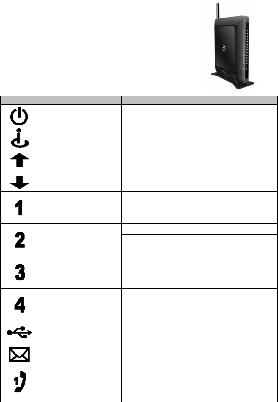
Front Panel and LEDs
There are fourteen Light-Emitting-Diodes (LEDs) located on the
front panel top provide status information to the user.
LED NAME COLOR MODE STATUS
On Connected with power
Power Green
Off Power failure or disconnect
Blinking TFTP/DHCP in process
Cable Green
On Cable connected
On Upstream Data traffic
Tx Green
Off Without data
Rx Green On Downstream Data traffic
Blinking Connecting
On Ethernet port 1 linked
LAN 1 Green
Off Disconnected
Blinking Connecting
On Ethernet port 2 linked
LAN 2 Green
Off Disconnected
Blinking Connecting
On Ethernet port 3 linked
LAN 3 Green
Off Disconnected
Blinking Connecting
On Ethernet port 4 linked
LAN 4 Green
Off Disconnected
Blinking USB activity
USB Green
On USB linked
Blinking Off hook
Voice
Message Green On VoIP linked
Blinking New voice message or in calling
On Line 1 is registered in the network
TEL1 Green
Off Line 1 is not registered in the
network
CBV704EW Series Cable Modem
User’s Manual
4
Blinking
New voice message or in calling
On Line 2 is registered in the network
TEL2 Green
Off Line 2 is not registered in the
network
Blinking No phone call
Wifi Green
On Connecting
Blinking WPS Activating WPS
WPS
Blue On WPS Connected
Off No WPS Connection
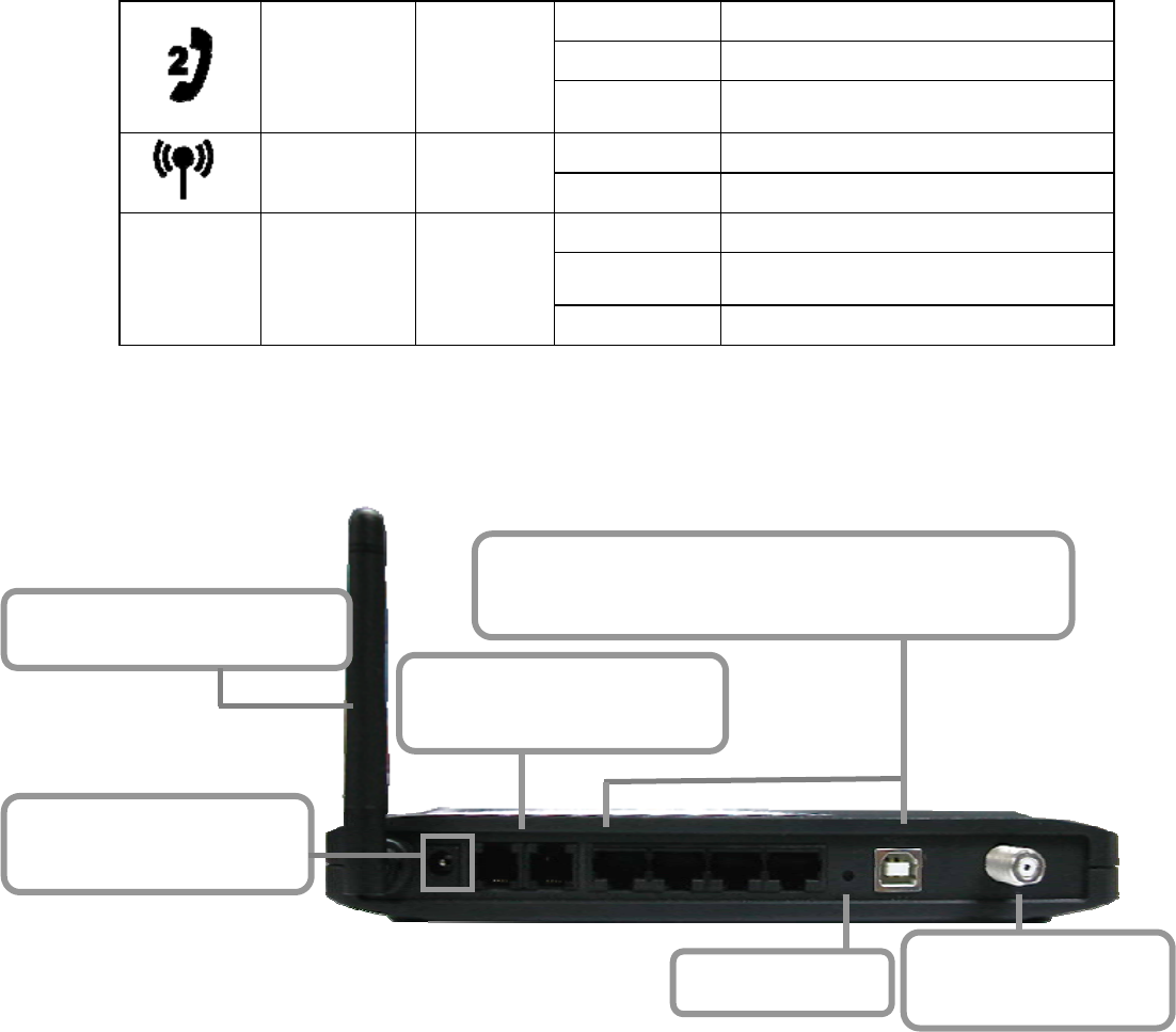
2.2 Rear Panel and Hardware Connection
This chapter describes the proper steps for connecting your cable modem.
Please be sure to follow the steps in the sequence outlined below. Failure to
do so could result in improper operation or failure of your cable modem.
Step 1:
Connect a cable by feeding the F-connector on the back of the cable modem.
Ensure the center conductor of the 75 ohm coaxial cable is inserted directly
into the center of the F-connector. Secure the coaxial cable by carefully
threading the outer shell of the coaxial cable connector onto the F-connector
in a clockwise direction until tight. Be careful not to over-tighten the connector
or you may damage either the connector or the cable modem.
Step2: Connect the cable modem to an IEEE 802.3 10BaseT / 802.3u
100Base-TX Network using a RJ-45 male-terminated Ethernet cable or an
USB cable to the PC. This cable modem equips with two Ethernet ports, you
can connect two PCs to the cable modem at the same time if necessary.
Step 3: Connect the telephone sets to TEL1 and TEL2. Use RJ-11 telephone
line to connect TEL1/TEL2 port on the cable modem and telephone socket on
telephone.
Step 1 Connecting
the Coaxial Cable
Step 3 Connecting the
Telephone cord
Step 5 Adjust the Antenna
Step 4 Connecting to
the AC Adapter
Step 2 Connecting to a Network Interface Card
Or Connecting to the USB port on your PC
Reset Button
CBV704EW Series Cable Modem
User’s Manual
5
Step 4: Connect the AC Adapter to the cable modem by inserting the barrel-
shaped connector into the mating power connector on the back of the cable
modem. Exercise carefully to ensure the connectors are properly aligned prior
to insertion and ensure the two connectors engage completely. The cable
modem is shipped with an AC adapter. Remember to use only power adapter
that came with the cable modem. Other power adapters might have voltages
that are not correct for your particular cable modem. Using a power adapter
with the wrong voltage can damage the cable modem.
Step 5: Adjust the antenna if necessary.
CBV704EW Series Cable Modem
User’s Manual
6
3. Ethernet Installation
The LAN port you are using is auto-negotiating 10/100Mbps (Switch) Ethernet
Interface. You can use the Ethernet port to connect to the Internet with an
Ethernet network device such as NIC/Hub/Switch through RJ45.
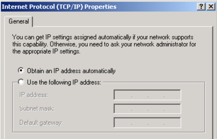
Before you connect to and install the cable modem, please set the IP address
to "Obtain an IP address automatically" as below and do ensure the TCP/IP
protocol is installed on your system and configured correctly in your PC.
Following is an example of configuring the TCP/IP Protocol on Windows 98
Operating Systems:
1. Click StartÆSettingsÆControl Panel. Double click on the Network icon
click Properties.
2. A list of installed network components appears. Look for an entry named
TCP/IP. This entry may be followed by an arrow and a description of the
NIC hardware device installed in the computer. If you don't see "TCP/IP"
listed anywhere in the "The following network components are installed"
box, click the Add button, choose Protocol, and click the Add button.
Select "Microsoft" as the manufacturer and then scroll down in the list on
the right to find "TCP/IP". If you see "TCP/IP" listed, proceed to step 4.
3. Click the OK button. You will be prompted to insert the Windows 98
installation/upgrade CD.
4. Scroll down in the box until you find a line that says "TCP/IP -> " followed
by the name of your Ethernet adapter. Click on Properties and choose
"Obtain an address automatically" which means that your PC has been
configured to use DHCP (Dynamic Host Configuration Protocol).
5. Click OK.
Congratulations! You have successfully set up your cable modem.
CBV704EW Series Cable Modem
User’s Manual
7
4. USB Driver Installation
Using the USB port to connect to the Internet allows you to install the cable
modem more quickly and easily than connecting to the Internet using the
Ethernet port, since you do not need to install a network interface card (NIC).
Windows XP
1. Connect USB cable from PC to cable modem.
2. Connect RF cable and power on Cable Modem. Wait until it register, it will
take about 40 seconds to 4 minutes depends on network traffic. Cable
Modem may reboot if you previously connect it through Ethernet port.
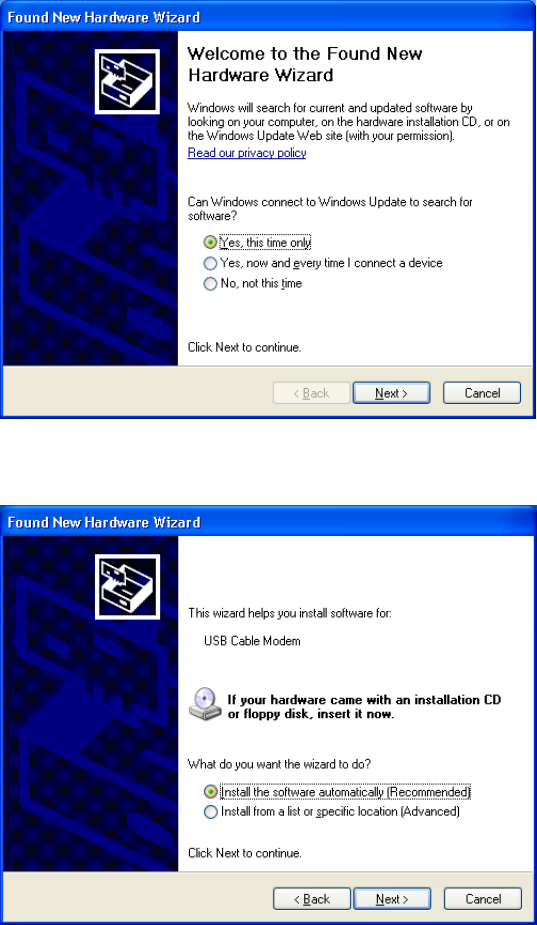
3. Windows will prompt new hardware found, insert the Driver CD into your
CD-ROM drive.
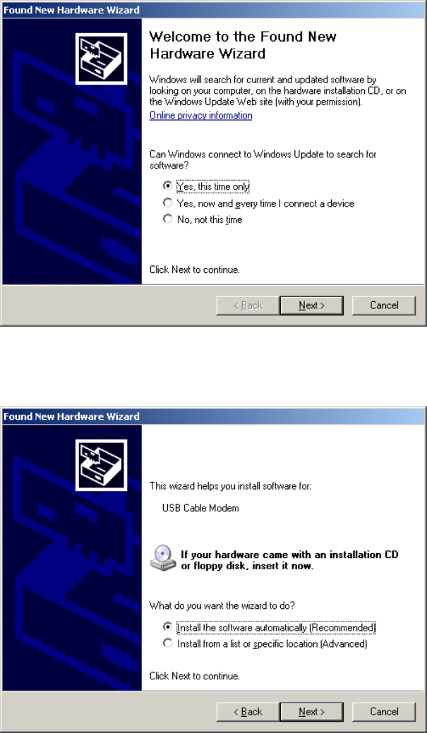
4. You may seed this window if you had update your Windows XP to
Service Pack 2. Select “Yes, this time only” and then click Next.
5. Select “Install the software automatically (Recommended)” and then click
Next.
CBV704EW Series Cable Modem
User’s Manual
8
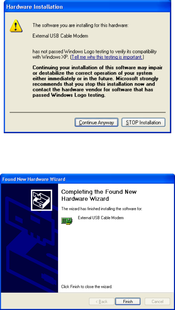
6. Windows will locate the driver automatically. Please click Continue
Anyway to continue the installation process.
7. Windows shall find the location of USB driver and complete the
installation. Click Finish.
CBV704EW Series Cable Modem
User’s Manual
9
Windows 2003
1. Connect USB cable from PC to cable modem.
2. Connect RF cable and power on Cable Modem. Wait until it register, it will
take about 40 seconds to 4 minutes depends on network traffic. Cable
Modem may reboot if you previously connect it through Ethernet port.
3. Windows will prompt new hardware found, insert the Driver CD into your
CD-ROM drive.
4. Select “Yes, this time only” and then click Next.
5. Select “Install the software automatically (Recommended)” and then click
Next.
CBV704EW Series Cable Modem
User’s Manual
10
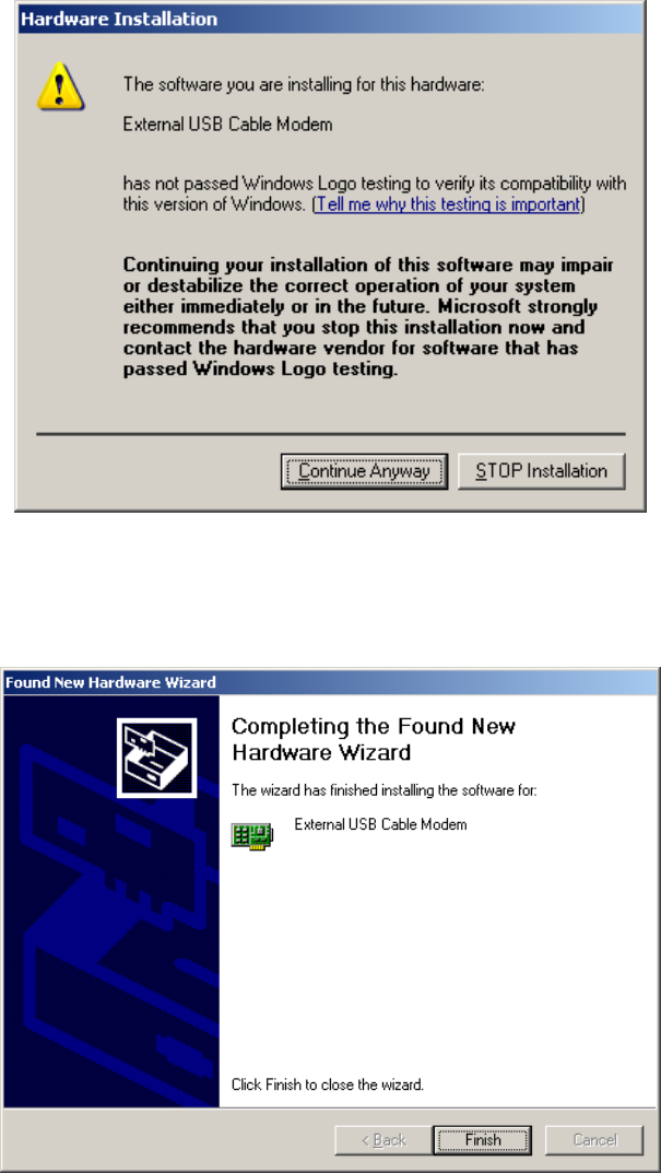
6. Windows will locate the driver automatically. Please click Continue
Anyway to continue the installation process.
7. Windows shall find the location of USB driver and complete the
installation. Click Finish.
CBV704EW Series Cable Modem
User’s Manual
11
Windows Vista
1. Connect USB cable from PC to cable modem.
2. Connect RF cable and power on Cable Modem. Wait until it register, it will
take about 40 seconds to 4 minutes depends on network traffic. Cable
Modem may reboot if you previously connect it through Ethernet port.
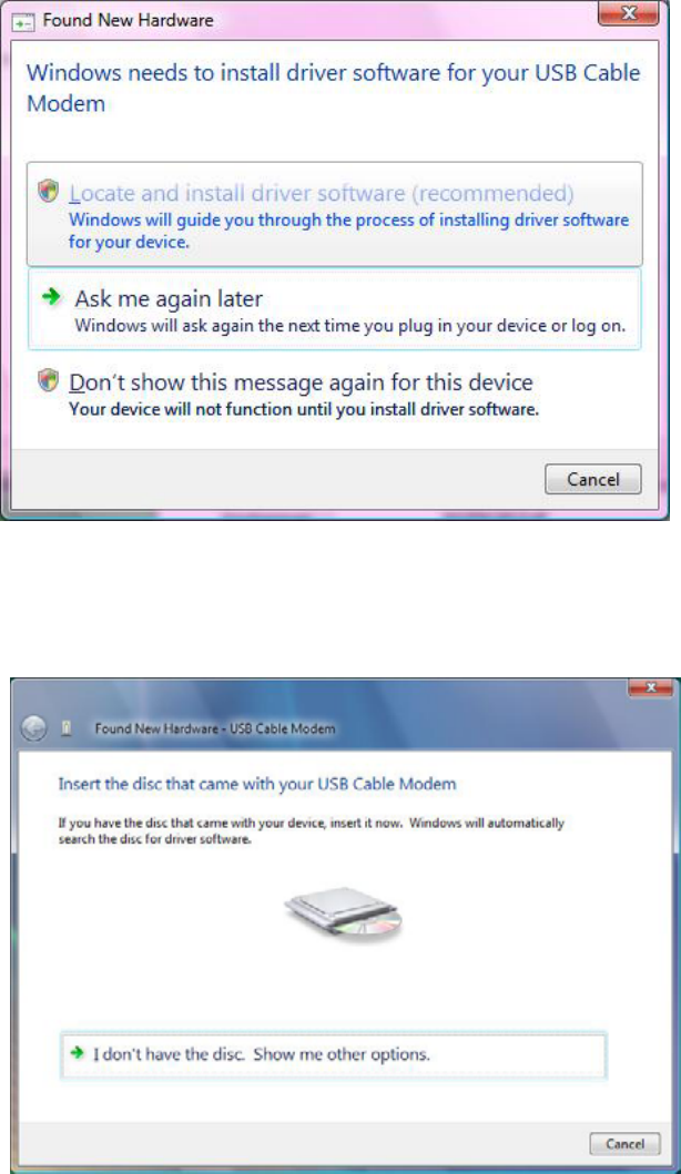
3. Windows will prompt new hardware found, insert the Driver CD into your
CD-ROM drive.
4. Click “Locate and install driver software (recommended)” item
5. Insert the Driver disk that came with your cable modem into your CD-
ROM drive. Windows Vista will automatically searched and found this
driver.
CBV704EW Series Cable Modem
User’s Manual
12
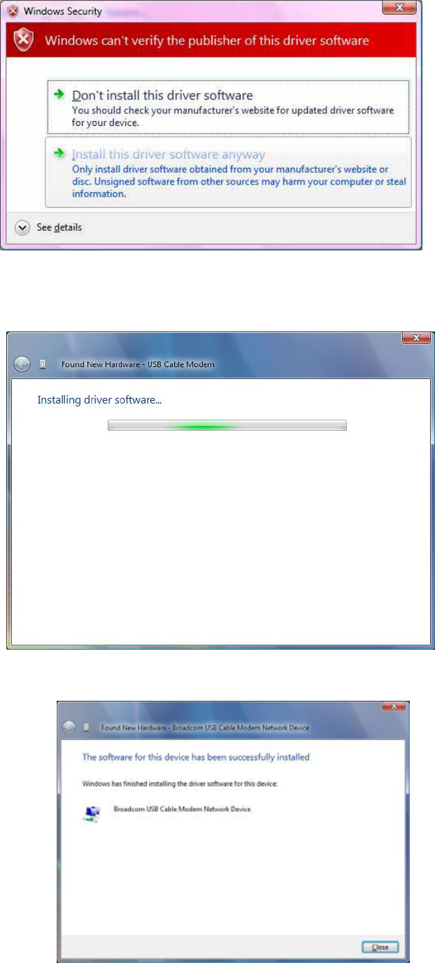
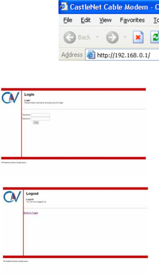
6. During the driver installation, your system may pop-up a dialogue as
below window, just click “Install this driver software anyway”.
7. During the driver installation, your system may pop-up a dialogue as
below window, just click “Install this driver software anyway”.
8. Click “Close” button to finish the driver installation.
CBV704EW Series Cable Modem
User’s Manual
13
5. Web Management
For easy-changing the default setting or quick-checking diagnostics for
troubleshooting, a Web-based GUI is built-in for your access.
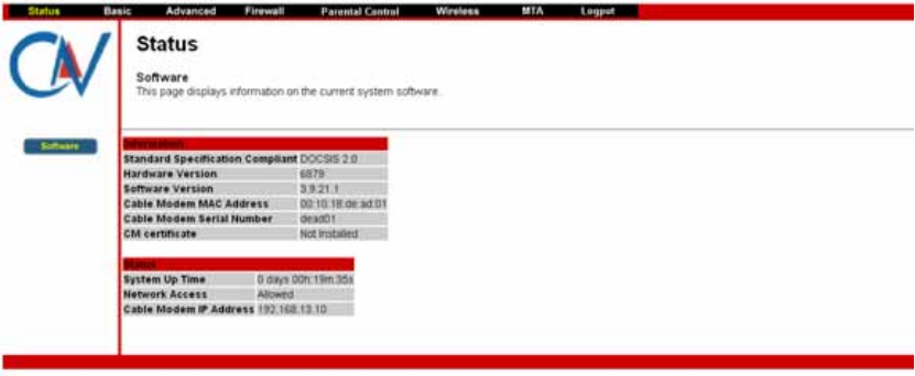
Enter Modem's IP address
Use the following procedures to login to your CBV704EW.
1. Open your web browser.
You may get an error message. This is normal. Continue on to the next
step.
2. Type the default IP address of the CBV704EW (e.g. 192.168.0.1) and
press Enter.
3. The Log In page appears. Type the user name (admin) and your
password (password) in the respective fields.
4. click the Logout button to leave the application.
There are seven categories in this web management including Status, Basic,
Advanced and Firewall. The following sections describe their details.
CBV704EW Series Cable Modem
User’s Manual
14
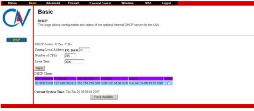
Status
The Status page shows hardware and software information about the
CBV704EW that may be useful to your cable service provider.
5.1.1 Software Status
The Software page shows how long the CBV704EW has operated since last
being powered up, and some key information the CBV704EW received during
the initialization process with your cable service provider.
If Network Access shows “Allowed,” then your cable service provider has
configured the CBV704EW to have Internet connectivity. If Network
Access shows otherwise, you may not have Internet access, and please
contact your cable service provider for assistance.
Basic
The Basic page contains the basic features of CBV704EW including Setup,
DHCP and Backup
CBV704EW Series Cable Modem
User’s Manual
15
5.1.2 DHCP
The DHCP page allows you to activate/deactivate the DHCP server function
of the CBV704EW, and, if the DHCP server is activated, to see DHCP leases
it has provided.
With this function activated, your cable service provider’s DHCP server
provides one IP address for the CBV704EW, and the CBV704EW’s DHCP
server provides IP addresses, starting at the address you set in Starting
Local Address field, to your PCs. A DHCP server leases an IP address with
an expiration time.
To set the maximum number of PCs to which the CBV704EW will issue IP
addresses, enter it in the Number of CPEs box and then click Apply. (CPE is
another term sometimes used for PC.)
The table on the bottom of this page shows the information of DHCP clients
including the IP and MAC addresses of each PC. Since MAC addresses are
unique and permanently fixed into hardware, you can identify any PC listed by
its MAC address. The CBV704EW provides leases for 3600 seconds (default),
and has an automatic renewal mechanism that will keep extending a lease as
long as the associated PC remains active.
You can cancel an IP address lease by selecting it in the DHCP Client Lease
Info list and then clicking the Force Available button. If you do this, you may
have to perform a DHCP Renew on that PC, so it can obtain a new lease.
Advanced
The Advanced page allows you to enable/disable some advanced features of
the CBV704EW.
CBV704EW Series Cable Modem
User’s Manual
16
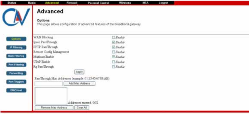
5.1.3 Options
The Options page allows you to enable/disable some advanced features
supported by CBV704EW.
Check the option you want to use and click Apply button to enable the
function(s).
z WAN Blocking: To prevent others on the WAN side from being able to
ping your CBV704EW. With WAN Blocking on, your CBV704EW will not
respond to pings it receives, effectively “hiding” your gateway.
z Ipsec PassThrough: To enable IpSec type packets to pass through
between WAN and LAN.
z PPTP PassThrough: To enable PPTP type packets to pass through
between WAN and LAN.
z Remote Config Management: To make the Web Management pages of
your CBV704EW accessible from the WAN side. Page access is limited
to only those who know the CBV704EW access password you set in the
Status--Security page.
When accessing the CBV704EW from a remote location, you must use
HTTP port 8080 and your IP address. This is the "WAN IP address" that
appears at the Basic--Setup page. For example, if this IP address were
211.20.15.28, you would navigate to http:// 211.20.15.28:8080 to reach
the CBV704EW’s Web Management page from a remote location.
z Multicast Enable: To enable multicast traffic to pass through between
WAN and LAN. You may need to enable this to see some types of
broadcast streaming and content on the Internet, such as webcasting of a
popular live event.
z UPnP Enable: UPnP (Universal Plug and Play) offers pervasive peer-to-
peer network connectivity of PCs of all form factors, intelligent appliances,
and wireless devices. UPnP architecture leverages TCP/IP and the Web
to enable seamless proximity networking in addition to control and data
transfer among networked devices in the home, office, and everywhere in
between.
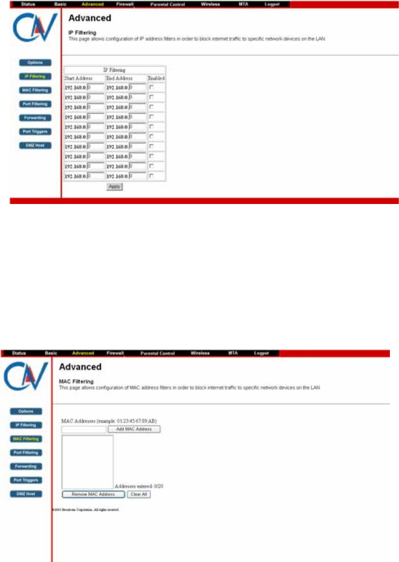
5.1.4 IP Filtering
The IP Filtering page enables you to enter the IP address ranges of PCs on
your LAN that you don’t permit to have outbound access ability to the WAN.
CBV704EW Series Cable Modem
User’s Manual
17
These PCs can still communicate with each other on your LAN, but packets
they originate to WAN addresses are blocked by the CBV704EW.
To enable IP Filtering feature of CBV704EW, check the Enable box and click
Apply button.
5.1.5 MAC Filtering
The MAC Filtering page enables you to enter the MAC address of specific
PCs on your LAN that you don’t permit to have outbound access ability to the
WAN. These PCs can still communicate with each other through the
CBV704EW, but packets they send to WAN addresses are blocked.
To enable MAC filtering feature of CBV704EW, enter the MAC address of the
LAN device and click Apply button.
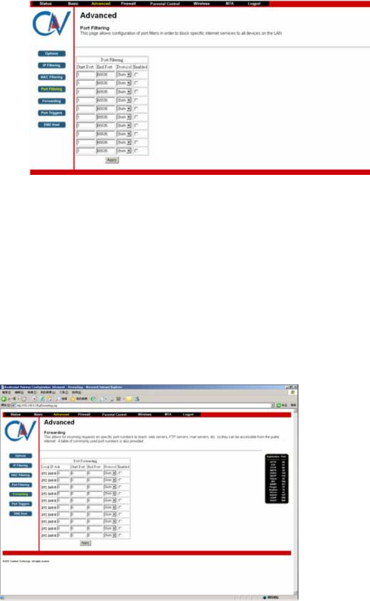
5.1.6 Port Filtering
The Port Filtering page allows you to enter ranges of destination ports
(applications) that you don’t want your LAN PCs to send packets to. Any
packets your LAN PCs send to these destination ports will be blocked. For
CBV704EW Series Cable Modem
User’s Manual
18
example, you could block access to worldwide web browsing (HTTP port 80)
but still allow email service (SMTP port 25 and POP3 port 110).
To enable port filtering, enter the Start port and End port for each range.
Then select its protocol form the drop-down list and check the Enable box,
and click Apply button. To block only one port, set both Start and End ports
the same.
5.1.7 Forwarding
For communications between LAN and WAN, the CBV704EW normally only
allows you to originate an IP connection with a PC on the WAN; it will ignore
attempts of the WAN PC to originate a connection onto your PC. This protects
you from malicious attacks from outsiders. However, sometimes you may wish
for anyone outside to be able to originate a connection to a particular PC on
your LAN if the destination port (application) matches one you specify.
The Forwarding page allows you to specify up to 10 rules.
Using the Port Forwarding page, you can provide local services (web servers,
FTP servers, mail servers, etc) for people on the Internet or play Internet
games. A table of commonly used port numbers is also provided.
CBV704EW Series Cable Modem
User’s Manual
19
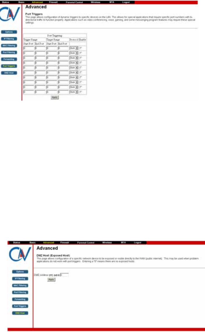
5.1.8 Port Triggers
The Port Triggers page allows you to configure dynamic triggers to specific
devices on the LAN. This allows for special applications that require specific
port numbers with bi-directional traffic to function properly. Applications such
as video conferencing, voice, gaming, and some messenging program
features may require these special settings.
Port Triggering is an elegant mechanism that does the forwarding for you,
each time you play the game.
You can specify up to 10 port ranges on which to trigger.
5.1.9 DMZ Host
The DMZ page allows you to configure a specific network device to be
exposed or visible directly to the WAN (public Internet). Setting a host on your
local network as demilitarized zone (DMZ) forwards any network traffic that is
not redirected to another host via the port forwarding feature to the IP address
of the host (PC). This designates one PC on your LAN that should be left
accessible to all PCs from the WAN side for all ports. For example, if you
locate a HTTP server on this machine, anyone will be able to access that
HTTP server by using your CBV704EW’s IP address as the destination. This
may be used when problem applications do not work with port triggers. The
setting of “0” indicates NO DMZ PC.
CBV704EW Series Cable Modem
User’s Manual
20
Firewall
The CBV704EW provides built-in firewall functions, enabling you to protect the
system against denial of service (DoS) attacks and other unwelcome or
malicious accesses to your LAN.
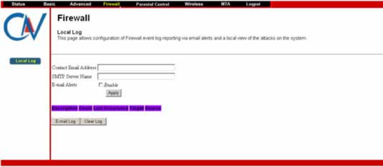
5.1.10 Local Log
The Local Log page allows you to configure the firewall event log reported via
email alert, and these attack records are also visible in the table on the bottom
of this page.
Specifies the e-mail address and its SMTP of the administrators who should
receive notices of any attempted firewall violations. Type the addresses in
standard Internet e-mail address format, for example,
yourname@onecompany.com. Then check the Enable box to enable the alert
feature.
Click E-mail Log to immediately send the email log. Click Clear Log to clear
the table of entries for a fresh start.
CBV704EW Series Cable Modem
User’s Manual
21
Parental Control
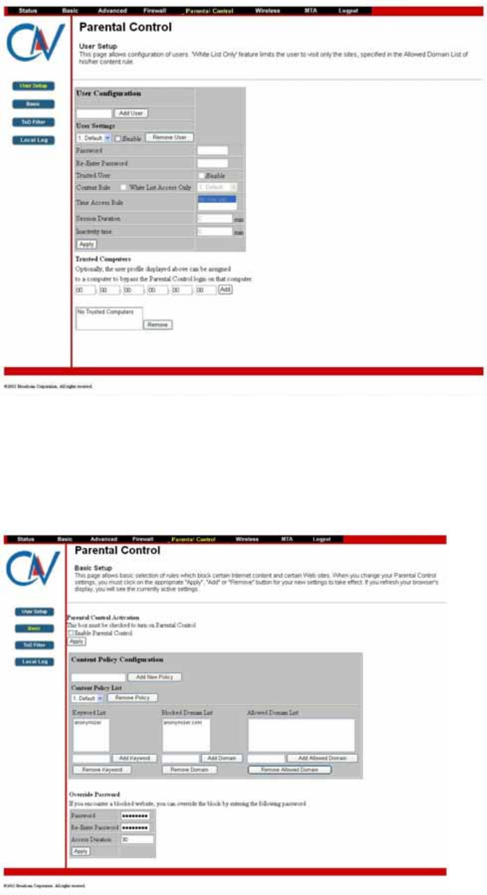
5.6.1 User Setup
This page allows configuration of users. “White List Only” feature limits the
user to visit only the sites, specified in the Allowed Domain List of his/her
content rule.
5.6.2 Basic Setup
This page allows basic selections of rules which block certain Internet content
and certain Web sites. When you change your Parental Control settings, you
must click on the appropriate “Apply”, “Add” or “Remove” button for your new
setting to take effect. If you refresh your browser’s display, you will see the
currently active settings.
CBV704EW Series Cable Modem
User’s Manual
22
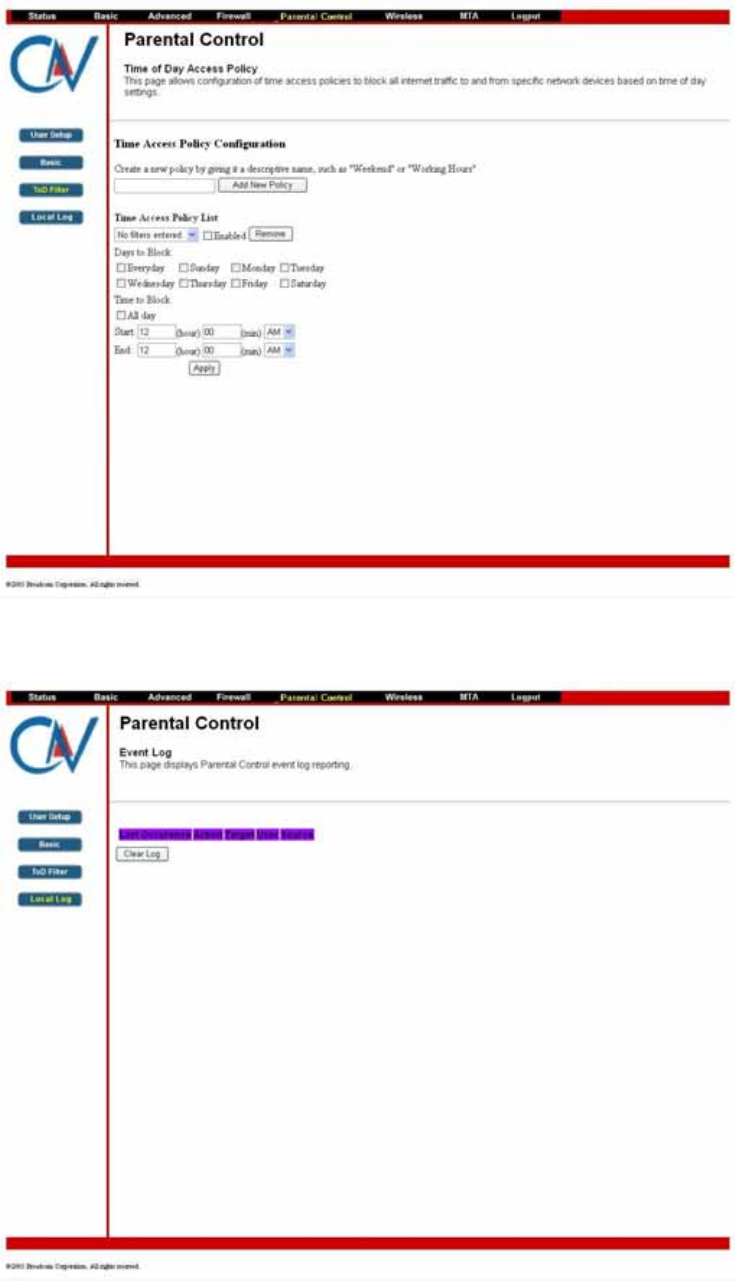
5.6.3 Time of Day Access Policy
This page allows configuration of time access policies to block all internet
traffic to and from specific network devices based on time of day setting.
5.6.4 Event Log
This page displays Parental Control event log reporting.
CBV704EW Series Cable Modem
User’s Manual
23
Wireless
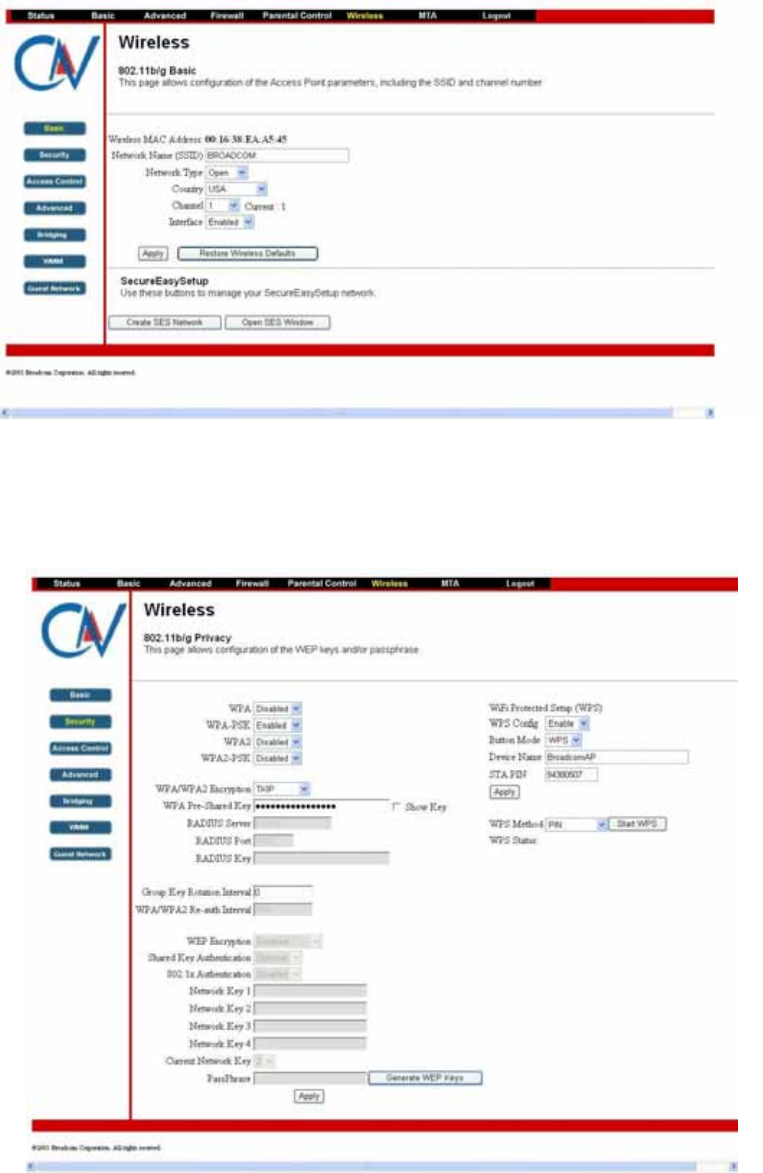
5.1.11 Basic
The Wireless Connection Status page allows configuration of the Access
Point parameters including the SSID and channel number.
5.1.12 Security
This page allows configuration of the WEP keys and/or passphrase.
CBV704EW Series Cable Modem
User’s Manual
24
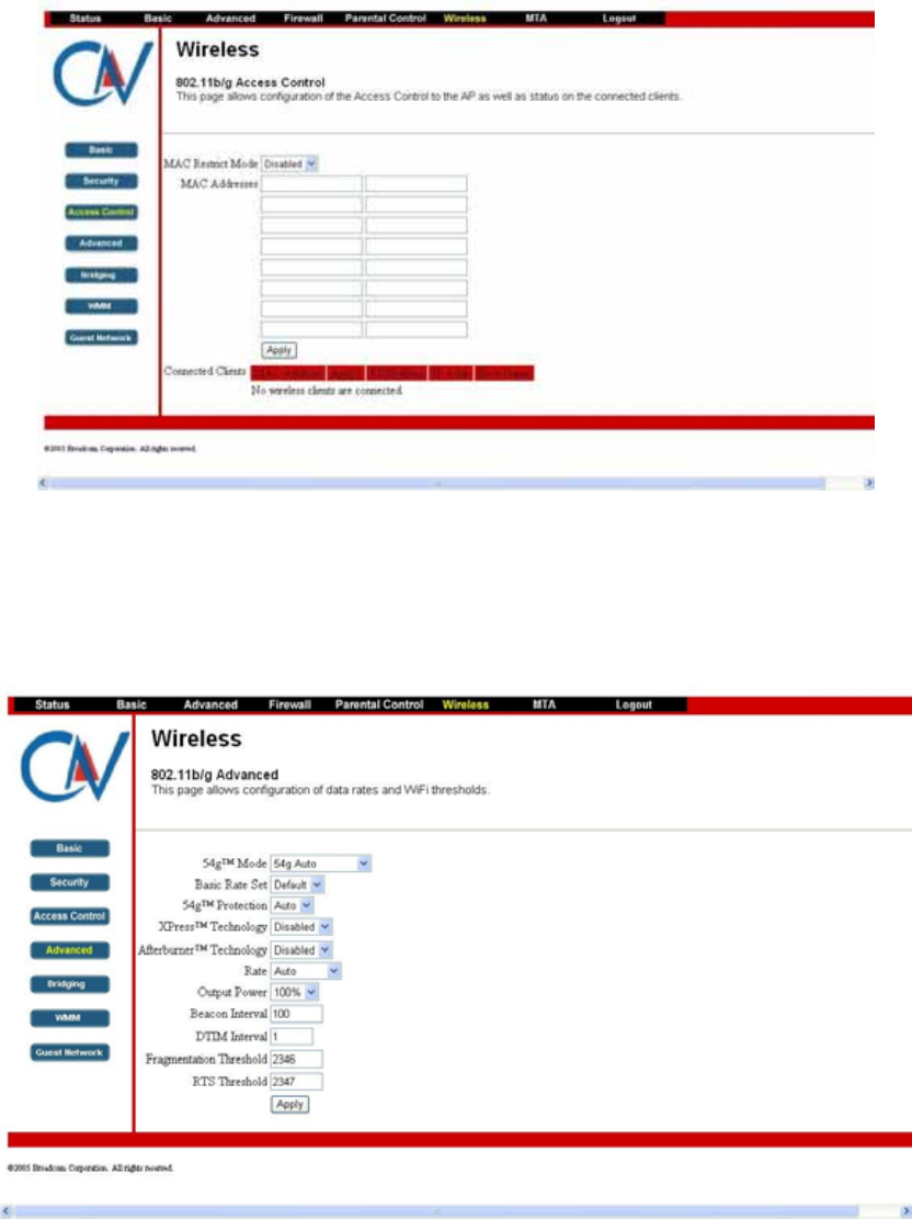
5.1.13 Access Control
This page allows configuration of the Access Control to the AP as well as on
the connected clients.
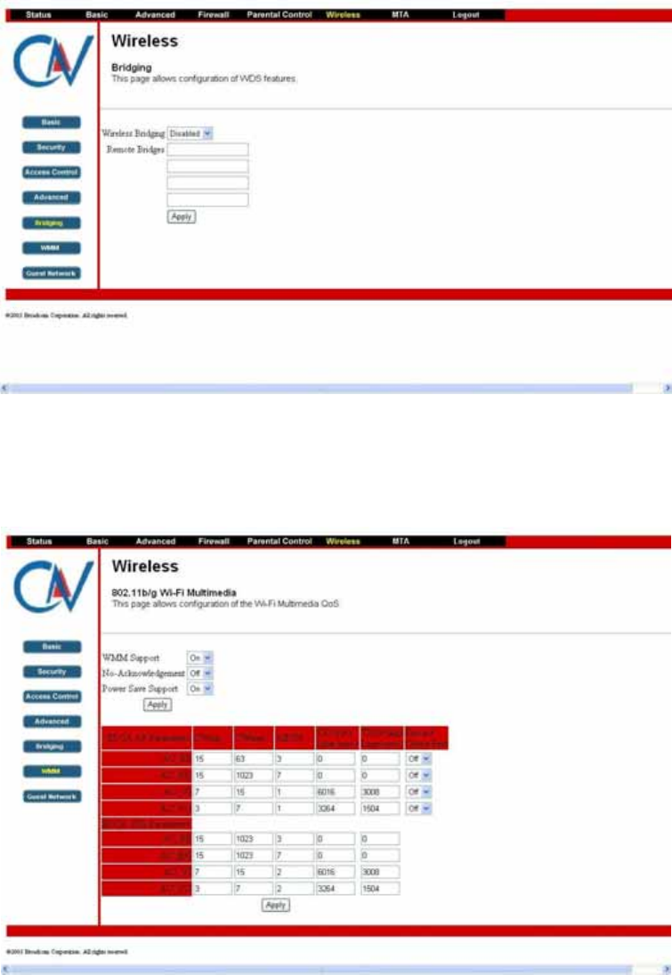
5.1.14 Advanced
This page allows configuration of data rates and WiFi thresholds.
CBV704EW Series Cable Modem
User’s Manual
25
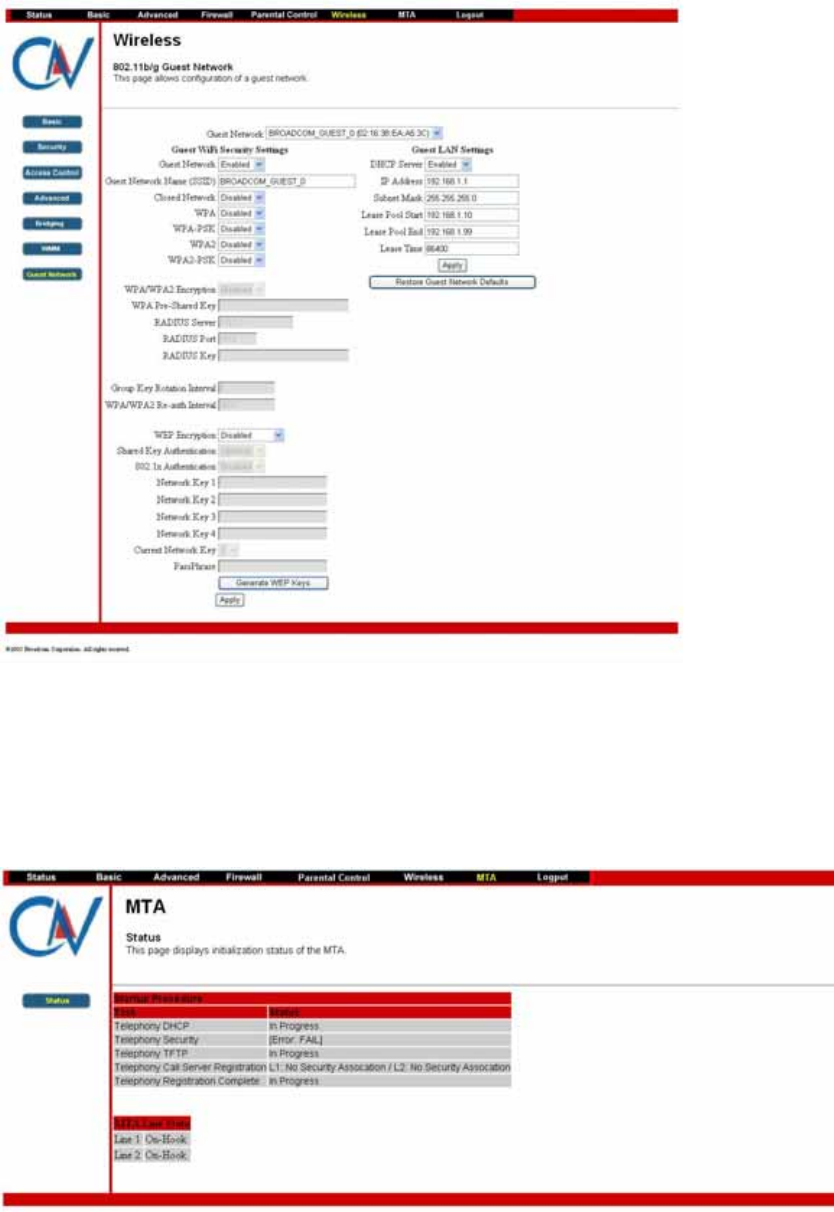
5.1.15 Bridging
This page allows configuration of WDS features.
5.1.16 WMM
This page allows configuration of the Wi-Fi Multimedia QoS.
5.1.17 Guest Network
This page allows configuration of a guest network..
CBV704EW Series Cable Modem
User’s Manual
26
MTA
Section MTA has 5 sub-items, which indicate the status of MTA. These
information can help you to understand the parameters of MTA operation.
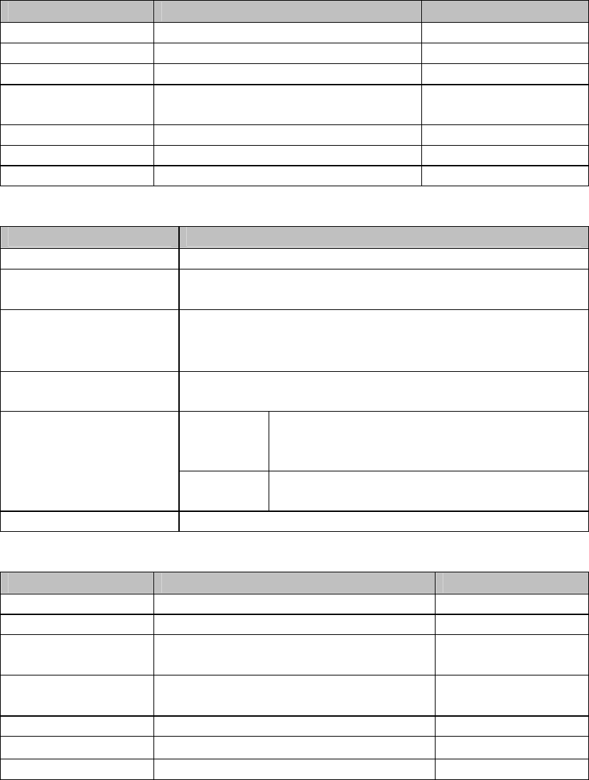
5.1.18 Status
This page displays initialization status of the MTA.
CBV704EW Series Cable Modem
User’s Manual
27
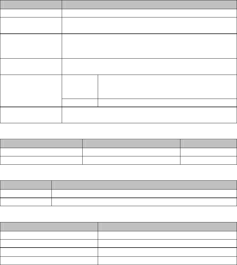
Appendix: Cable Modem Specification
Table 1. RF Downstream Specification (DOCSIS)
Parameter Value Notes
Frequency range 88 MHz to 860 MHz +/- 30 kHz
Demodulation 64QAM. 256QAM
Input power range -15 dBmV to +15 dBmV One Channel
Symbol Rate 5.056941 Msym/sec (30 Mbps)
5.360537 Msym/sec (43 Mbps) 64QAM 256QAM
Bandwidth 6 MHz
Total Input Power <30 dBmV
Input Impedance 75 Ohms
Table 2. RF Upstream Specification (DOCSIS)
Parameter Value
Frequency Range 5 MHz to 42 MHz
Modulation QPSK, 8QAM, 16QAM, 32QAM, 64QAM, 128QAM
(SCDMA only)
Symbol Rate TDMA: 160K, 320K, 640K, 1280K, 2560K,
5120Ksym/sec
S-CDMA: 1280K, 2560K, 5120Ksym/sec
Bandwidth TDMA: 200K, 400K, 800K, 1600K, 3200K,
6400KHz S-CDMA: 1600K, 3200K, 6400KHz
TDMA QPSK: 8 ~ 58 dBmV
8/16QAM: 8 ~ 55 dBmV
32/64QAM: 8 ~ 54 dBmV
Output power
S-CDMA QPSK, 8/16/32/64/128QAM: 8 ~ 53
dBmV
Output Impedance 75 Ohms
Table 3. RF Downstream Specification (for EuroDOCSIS system)
Parameter Value Notes
Frequency Range 108 MHz to 862 MHz
Demodulation 64QAM. 256QAM
Input power range +13dBmV to -17dBmV (65QAM)
+17dBmV to -13dBmV (256QAM)
Symbol Rate 056941 Msym/sec (30 Mbps)
5.360537 Msym/sec (43 Mbps) 64QAM 256QAM
Bandwidth 8MHz
Total Input Power <30 dBmV
Input Impedance 75 Ohms
CBV704EW Series Cable Modem
User’s Manual
28
Table 4. RF Upstream Specification (for EuroDOCSIS system)
Parameter Value
Frequency Range 5 MHz to 65 MHz
Modulation QPSK, 8QAM, 16QAM, 32QAM, 64QAM, 128QAM
(TCM only)
Symbol Rate TDMA: 160K, 320K, 640K, 1280K, 2560K,
5120Ksym/sec
S-CDMA: 1280K, 2560K, 5120Ksym/sec
Bandwidth TDMA: 200K, 400K, 800K, 1600K, 3200K, 6400KHz
S-CDMA: 1600K, 3200K, 6400KHz
TDMA QPSK: 8 ~ 58 dBmV
8/16QAM: 8 ~ 55 dBmV
32/64QAM: 8 ~ 54 dBmV
Output power
S-CDMA QPSK, 8/16/32/64/128QAM: 8 ~ 53 dBmV
Output
Impedance 75 Ohms
Table 5. Electrical Specification
Parameter Measured Value Notes
Input Voltage 15VDC/1A
Power consumption < 9.5W With AC adaptor
Table 6. Physical Specification
Parameter Value
Size 155 mm (L) x 37mm(W) x 260 mm (H)
Weight 360g +/- 10g (Modem only)
Table 7. Environmental Specification
Parameter Value
Operating Temperature 0 °C to +40 °C
Operating Relative Humidity 10% to 90% (Non-condensing)
Operating Altitude -100 to +7,000 feet
Storage Temperature -10 °C to +60 °C

CBV704EW Series Cable Modem
User’s Manual
29
Table 8. RF Specification
Parameter Value
Frequency Band 2.412 – 2.462GHz(2.4GHz ISM Band)
Number of Channels 11 Channels.
Modulation DBPSK,DQPSK,CCK DSSS for 802.11b &
g; DPSK,QPSK,16QAM OFDM for 802.11g
Supported Rates 1,2,5.5,11 Mbps for
802.11b;6,9,12,18,24,36,48,54 Mbps for
802.11g
Maximum Receive Level -20dBm (with PER<10%) for 802.11g
Antenna External (Hirose U-F-L)
11g PER-Compliant Output
Power (Typlcal) 11b: 17dBm
11g: 16dBm
Note: Actual output power may vary based
on manufacturing process variations
Under Storage Temperature: -10℃ to + 45℃ ambient
temperature.
Humidity: 95% (non-condensing)
This document is subject to change without notice.