CastleNet Technology CGA0101CHL WIFI cable modem router User Manual Generic CGA0101 QIG
CastleNet Technology Inc. WIFI cable modem router Generic CGA0101 QIG
Users Manual
CGA0101 Wireless Cable Gateway Quick Installation Guide
Package Contents
CGA0101 cable modem * 1
Quick Installation Guide * 1
RJ-45 CAT 5e cable * 1
12 V/1.5 A Power Adaptor * 1
Telephone cord * 1
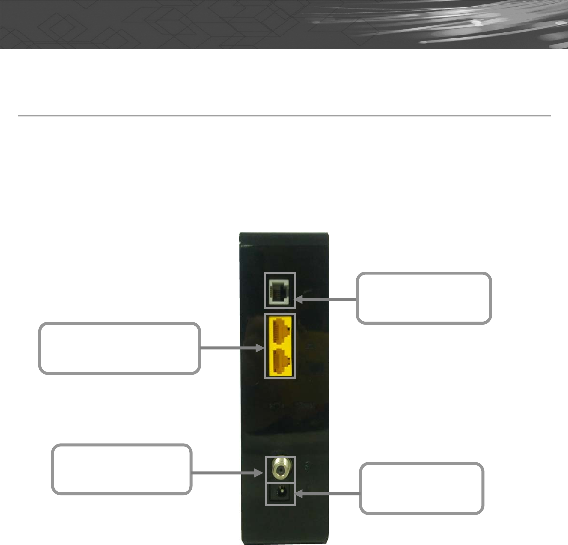
Rear Panel and Hardware Connection
This chapter describes the proper steps for connecting your cable modem. Please be sure to follow
the steps in the sequence outlined below. Failure to do so could result in improper operation or failure
of your cable modem.
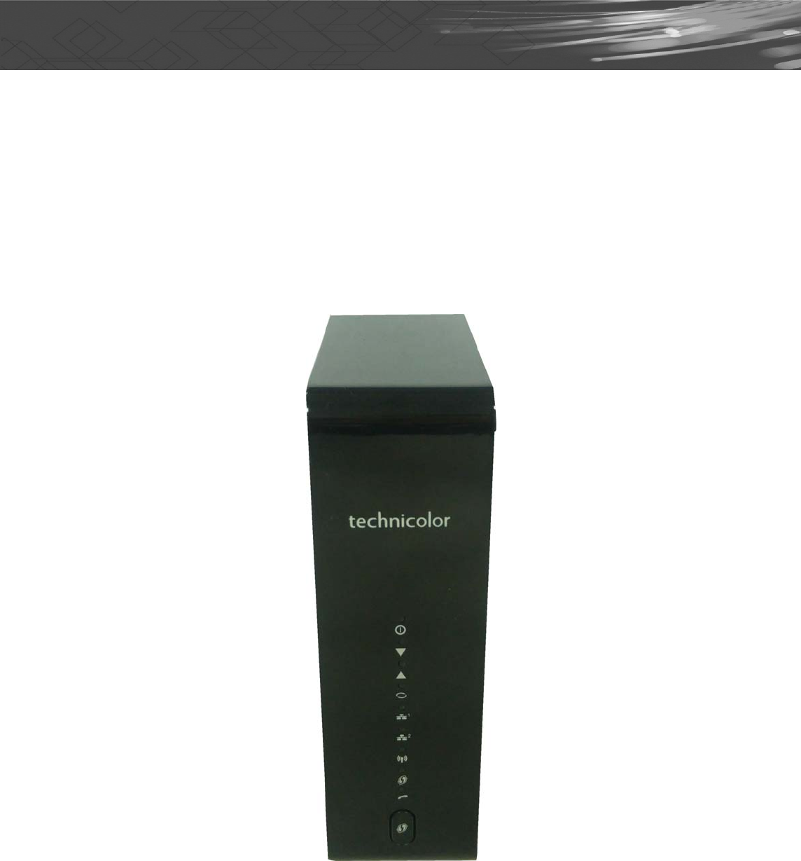
Please be reminded this product CGA0101 is designed to stand in vertical position in order to keep the
ventilation as clear as possible. Please do not put it down horizontally.
Step 1: Connect a cable by feeding the F-connector on the back of the cable modem. Ensure the
center conductor of the 75 ohm coaxial cable is inserted directly into the center of the F-connector.
Secure the coaxial cable by carefully threading the outer shell of the coaxial cable connector onto the
F-connector in a clockwise direction until tight. Be careful not to over-tighten the connector or you may
damage either the connector or the cable modem.
Step 2: Connect the cable modem to IEEE 802.3 10Base-T / 802.3u 100Base-TX / 802.3ab
1000Base-T Network using a RJ-45 male-terminated Ethernet cable. This cable modem equips with
two Ethernet ports, you can connect two PCs to the cable modem at the same time if necessary.
Step 3: Connect the telephone sets to TEL. Use RJ-11 telephone line to connect TEL port on the
cable modem and telephone socket on telephone
Step 4: Connect the AC Adapter to the cable modem by inserting the barrel-shaped connector into the
mating power connector on the back of the cable modem. Exercise carefully to ensure the connectors
are properly aligned prior to insertion and ensure the two connectors engage completely. The cable
modem is shipped with an AC adapter. Remember to use only power adapter that came with the cable
Step 1 Connecting
the Coaxial Cable
Step 2 Connecting to a
Network Interface Cord
Step 3 Connecting
the Telephone cord
Step 4 Connecting
to the AC Adapter
CGA0101 Wireless Cable Gateway Quick Installation Guide
modem. Other power adapters might have voltages that are not correct for your particular cable
modem. Using a power adapter with the wrong voltage can damage the cable modem.
Step 5: Adjust the antenna if necessary.
Step 6:The screen of the coaxial cable is intended to be connected to earth in the building installation.
Front Panel & LEDs
There are nine Light-Emitting-Diodes (LEDs) located on the
front panel top provide status information to the user.
CGA0101 Wireless Cable Gateway Quick Installation Guide
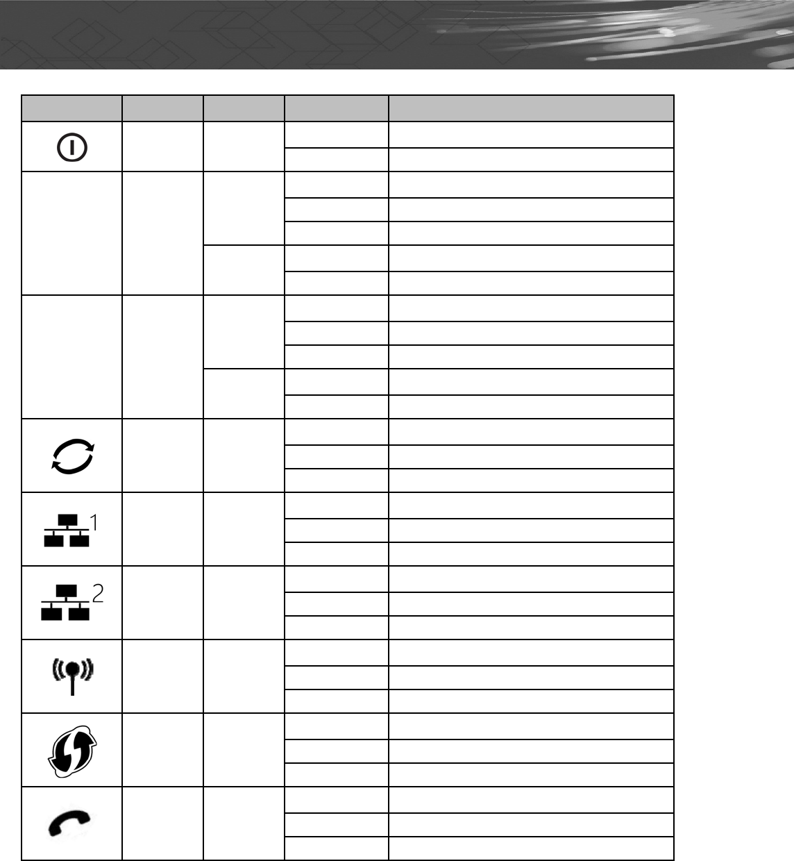
LEDNAMECOLORMODESTATUS
POWERGreenOnDC power connected
OffNo DC power connected
▼
DS
Green
BlinkingDownstream scanning
OnDownstream locked
OffCable interface idle
GreenOnW/DS locked
OffW/DS disabled or CM standby
▲
US
Green
BlinkingUpstream ranging
OnUpstream locked
OffCable interface idle
GreenOnW/US locked
OffW/US disabled or CM standby
ONLINEGreen
BlinkingCM provisioning
OnCM on-line
OffCable interface idle
LAN1
Green
& Orange
OnETH device connected (Green: GbE, Orange: FE)
BlinkingData in traffic
Off No ETH device connected
LAN2
Green
& Orange
OnETH device connected (Green: GbE, Orange: FE)
BlinkingData in traffic
Off No ETH device connected
Wi-FiGreen
OnWiFi enabled
BlinkingData in traffic
OffWiFi disabled
WPSGreen
BlinkingWPS in paring
OnWPS enabled
OffWPS disabled
TELGreen
BlinkingTEL provisioning or off-hook
OnTEL on-hook
OffTEL disabled
CGA0101 Wireless Cable Gateway Quick Installation Guide
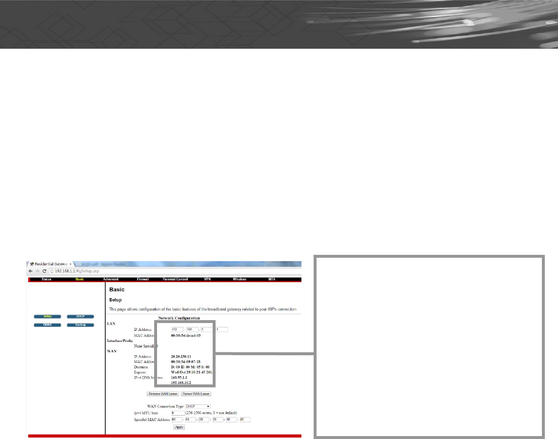
Accessing the Web Management
For easy-changing the default settings, a Web-based GUI is built-in for your access.
Use the following procedures to login to your CGA0101.
1. Open your web browser. Type the default IP address of the CGA0101 (e.g. http://192.168.0.1)
and press Enter.
Configuring Your WAN Connection
The DHCP page allows you to activate/deactivate the DHCP server function of the CGA0101, and, if
the DHCP server is activated, to see DHCP leases it has provided.
Enable CGA0101’s DHCP server to
allocate IP address to the connected
LAN client (PC) and configure the
Starting Local Address to be issued.
You can also set the maximum number
of PCs to which the CGA0101 will issue
IP addresses and the release time (in
second).

CGA0101 Wireless Cable Gateway Quick Installation Guide
Check your CGA0101 Access Information
There is a label pasted to the bottom of CGA0101 case. In that label, you can obtain following
information. Pls note, following label is just an example, each CGA0101 has their own label and
setting value. Pls follow your label information to access and configure CGA0101. In normal case, you
don’t need to change anything, all setting have been set and work properly.
SSID: This is used for your CGA0101 wireless setting use, and, this setting has already been set to
your CGA0101.
WPA Pre-Shared Key: This is the password for your wireless client when connecting to CGA0101.
You will be asked to key in this password so as to connect via wireless
connection.
Web Management: This is the URL when you like to access to CGA0101. You can simply type
http://192.168.0.1 in Microsoft Internet Explorer or any other internet browser to
access CGA0101 web management page.
Login: This is the value when accessing CGA0101 web management page. You will be asked to key
in this default value to access CGA0101.
Password: This is the value when accessing CGA0101 web management page. You will be asked to
key in this default value to access CGA0101.
SSID:
CGA0101_8C9D
WPA2-PSK(TKIP+AES)
Web Management:
http://192.168.0.1
login: admin
password: password

CGA0101 Wireless Cable Gateway Quick Installation Guide
Federal Communication Commission Interference Statement
This equipment has been tested and found to comply with the limits for a Class B digital device, pursuant to
Part 15 of the FCC Rules. These limits are designed to provide reasonable protection against harmful
interference in a residential installation. This equipment generates, uses and can radiate radio frequency
energy and, if not installed and used in accordance with the instructions, may cause harmful interference to
radio communications. However, there is no guarantee that interference will not occur in a particular
installation. If this equipment does cause harmful interference to radio or television reception, which can be
determined by turning the equipment off and on, the user is encouraged to try to correct the interference by one
of the following measures:
- Reorient or relocate the receiving antenna.
- Increase the separation between the equipment and receiver.
- Connect the equipment into an outlet on a circuit different from that to which the receiver is connected.
- Consult the dealer or an experienced radio/TV technician for help.
This device complies with Part 15 of the FCC Rules. Operation is subject to the following two conditions: (1)
This device may not cause harmful interference, and (2) this device must accept any interference received,
including interference that may cause undesired operation.
FCC Caution: Any changes or modifications not expressly approved by the party responsible for compliance
could void the user's authority to operate this equipment.
IMPORTANT NOTE:
FCC Radiation Exposure Statement:
This equipment complies with FCC radiation exposure limits set forth for an uncontrolled environment. To
maintain compliance with FCC RF exposure compliance requirements, please follow operation instruction
as documented in this manual.
This transmitter must not be co-located or operating in conjunction with any other antenna or transmitter.
This device is intended only for OEM integrators under the following conditions:
1) The antenna must be installed such that 20 cm is maintained between the antenna.
2) The transmitter module may not be co-located with any other transmitter or antenna.
As long as 2 conditions above are met, further transmitter test will not be required. However, the OEM integrator
is still responsible for testing their end-product for any additional compliance requirements required with this
module installed (for example, digital device emissions, PC peripheral requirements, etc.).

CGA0101 Wireless Cable Gateway Quick Installation Guide
IMPORTANT NOTE: In the event that these conditions can not be met (for example certain laptop
configurations or co-location with another transmitter), then the FCC authorization is no longer considered valid
and the FCC ID can not be used on the final product. In these circumstances, the OEM integrator will be
responsible for re-evaluating the end product (including the transmitter) and obtaining a separate FCC
authorization.
Manual Information To the End User
The OEM integrator has to be aware not to provide information to the end user regarding how to install or
remove this RF module in the user’s manual of the end product which integrates this module.
The users manual for OEM integrators must include the following information in a prominent location
“IMPORTANT NOTE: To comply with FCC RF exposure compliance requirements. The antenna must not be
co-located or operating in conjunction with any other antenna or transmitter.
FCC Statement
This device complies with Class B Part 15 of the FCC Rules. The device generates, uses and can
radiate radio frequency energy and, if not installed and used as instructed, may cause harmful
interference to radio communication. Only Coaxial cables are to be used with this device in order to
ensure compliance with FCC emissions limits. Accessories connected to this device by the user must
comply with FCC Class B limits. The manufacturer is not responsible for any interference which results
from use of improper cables, or which results from unauthorized changes or modifications to the
device.
"A Minimum 26 AWG Line Core should be used for connection to the cable modem"

CGA0101 Wireless Cable Gateway Quick Installation Guide
Canada-Industry Canada (IC)
Operation is subject to the following two conditions:
this device may not cause interference and
this device must accept any interference, including interference that may cause undesired operation of the
device.
IMPORTANT NOTE:
IC Radiation Exposure Statement:
This equipment with IC radiation exposure limits set forth for an uncontrolled environment. To maintain
compliance with IC RF exposure compliance requirements, please follow operation instruction as documented
in this manual.
Warranty
Items sold by manufacturer/distributor/agent, hereinafter called "Seller", are warranted only as follows:
Except as noted below Seller will correct, either by repair or replacement at its option, any defect of
material or workmanship which develops within one year after delivery of the item to the original Buyer
provided that evaluation and inspection by Seller discloses that such defect developed under normal
and proper use. Repaired or replaced items will be further warranted for the unexpired term of their
original warranty. All items claimed defective must be returned to Seller, transportation charges
prepaid, and will be returned to the Buyer with transportation charges collect unless evaluation proves
the item to be defective and that the Seller is responsible for the defect. In that case, Seller will return
to Buyer with transportation charge prepaid. Seller may elect to evaluate and repair defective items at
the Buyer's site. Seller may charge Buyer a fee (including travel expenses, if needed) to cover the cost
of evaluation if the evaluation shows that the items are not defective or that they are defective for
reasons beyond the scope of this warranty.
The Seller makes no warranty concerning components or accessories not manufactured by it.
However, in the event of failure of such a part, Seller will give reasonable assistance to Buyer in
obtaining from the manufacturer whatever adjustment is reasonable in light of the manufacturer's own
warranty. Seller will not assume expense or liability for repairs made outside the factory by other than
Seller's employees without Seller's written consent.
SELLER IS NOT RESPONSIBLE FOR DAMAGE TO ANY ASSOCIATED EQUIPMENT, NOR WILL
SELLER BE HELD LIABLE FOR INCIDENTAL, CONSEQUENTIAL, OR OTHER DAMAGES. THIS
WARRANTY IS IN LIEU OF ALL OTHER WARRANTIES EXPRESSED OR IMPLIED INCLUDING
THE IMPLIED WARRANTY OF "MERCHANTABILITY" AND "FITNESS FOR PARTICULAR
PURPOSE."
Note to CATV Sysrem Installer
"The EUT must be bonding the screen of the coaxial cable to the earth at the building entrance per
ANSI/NFPA 70, the National Electrical Code (NEC), in particular Section 820.93, Grounding of Outer
Conductive Shield of a Coaxial Cable.”
Trademarks
All trademarks are the property of their respective owners.