Caterpillar MSS3I Caterpillar MSS3i RFID Key Reader Module User Manual Exhibit D Users Manual per 2 1033 b3
Caterpillar, Inc. Caterpillar MSS3i RFID Key Reader Module Exhibit D Users Manual per 2 1033 b3
Exhibit D Users Manual per 2 1033 b3


Important Safety Information
Most accidents that involve product operation, maintenance and repair are caused by failure to observe
basic safety rules or precautions. An accident can often be avoided by recognizing potentially hazardous
situations before an accident occurs. A person must be alert to potential hazards, including human factors
that can affect safety. This person should also have the necessary training, skills and tools to perform these
functions properly.
Improper operation, lubrication, maintenance or repair of this product can be dangerous and could
result in injury or death.
Do not operate or perform any lubrication, maintenance or repair on this product, until you verify
that you are authorized to perform this work, and have read and understood the operation,
lubrication, maintenance and repair information.
Safety precautions and warnings are provided in this manual and on the product. If these hazard warnings
are not heeded, bodily injury or death could occur to you or to other persons.
The hazards are identified by the “Safety Alert Symbol” and followed by a “Signal Word” such as
“DANGER”, “WARNING” or “CAUTION”. The Safety Alert “WARNING” label is shown below.
The meaning of this safety alert symbol is as follows:
Attention! Become Alert! Your Safety is Involved.
The message that appears under the warning explains the hazard and can be either written or pictorially
presented.
A non-exhaustive list of operations that may cause product damage are identified by “NOTICE”labels on
the product and in this publication.
Caterpillar cannot anticipate every possible circumstance that might involve a potential hazard.
The warnings in this publication and on the product are, therefore, not all inclusive. You must not
use this product in any manner different from that considered by this manual without first satisfying
yourself that you have considered all safety rules and precautions applicable to the operation of the
product in the location of use, including site-specific rules and precautions applicable to the
worksite. If a tool, procedure, work method or operating technique that is not specifically
recommended by Caterpillar is used, you must satisfy yourself that it is safe for you and for others.
You should also ensure that you are authorized to perform this work, and that the product will not be
damaged or become unsafe by the operation, lubrication, maintenance or repair procedures that
you intend to use.
The information, specifications, and illustrations in this publication are on the basis of information that was
available at the time that the publication was written. The specifications, torques, pressures,
measurements, adjustments, illustrations, and other items can change at any time. These changes can
affect the service that is given to the product. Obtain the complete and most current information before you
start any job. Cat dealers have the most current information available.
When replacement parts are required for this
product Caterpillar recommends using Cat re-
placement parts.
Failure to follow this warning may lead to pre-
mature failures, product damage, personal in-
jury or death.
In the United States, the maintenance, replacement, or repair of the emission control devices and
systems may be performed by any repair establishment or individual of the owner's choosing.
i05296198

Table of Contents
Systems Operation Section
General Information..................... ..................... 4
System Overview....................... ....................... 5
Normal Operation ....................... ...................... 6
Operation of Status Indicator.............. .............. 7
Key Information......................... ........................ 8
Scheduled Access ( “Security System Bypass
Times”)............................. ............................ 10
Diagnostic Operation................... ................... 10
Protected Functions..................... ....................11
Service Operation Using Service Tool ...... .......11
Electronic Control Module (ECM) .......... ......... 12
System Components ................... ................... 12
Data Link............................. ............................ 13
Testing and Adjusting Section
Testing and Adjusting
General Information.................... .................... 15
Troubleshooting....................... ....................... 15
Key - Program......................... ........................ 15
Scheduled Access - Program (Security System
Bypass)............................. ............................ 25
Time - Set ............................ ........................... 26
Factory Password - Obtain ............... .............. 28
Configuration ......................... ......................... 34
Machine Security System - Uninstall....... ....... 41
Glossary of Terms...................... ..................... 42
System Schematic..................... ..................... 42
Index Section
Index................................ ............................... 43
UENR7000 3
Table of Contents

Systems Operation Section
i06195439
General Information
SMCS Code: 7631
The Caterpillar ®Machine Security System (MSS)
discourages unwanted operation of a machine. The
MSS uses the Caterpillar ®Electronic Key or a pass
code entered via a keypad or the machines display.
The keypad or machine display pass code feature is
only available on limited machines. Check the
machines Operation and Maintenance Manual to
verify that this feature is available. The Caterpillar
Electronic Key contains an electronic chip. The
electronic chip has a unique identification number
(ID). An exciter coil is mounted around the key start
switch. The exciter coil reads the ID of the key.
The Electronic Control Module (ECM) of the Machine
Security System is set up with the ID of the keys of
the intended users. When the MSS is armed, the
ECM validates the ID of the key in the key start
switch. If the key ID is in the list of authorized keys in
the ECM and the key is valid, the machine will
operate normally. If the key ID is not in the list of
authorized keys or is not valid in the ECM, the MSS
will keep the critical machine functions disabled.
Components
The Machine Security System consists of the
following components:
• Electronic Control Module (ECM)
• Caterpillar Electronic Key
• Caterpillar Optional key pad entry
• Exciter Coil
• Key Reader Module (MSS3i)
• Status Indicator
4UENR7000
Systems Operation Section
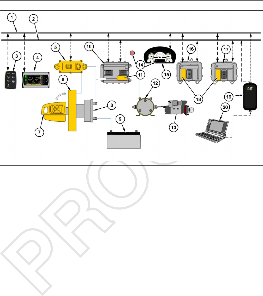
Illustration 1 g03864508
MSS3i Connections
(1) SAE J1939
(2) CAT Data Link
(3) External Keypad (Required for
Passcode Entry)
(4) Integrated Keypad (Required for
Passcode Entry)
(5) “Bouncer”(MSS3i) Electronic Key
Reader
(6) Exciter Coil
(7) Electronic Key
(8) Key Switch
(9) Battery 12V or 24V
(10) Critical System (Transmission ECM)
(11) MSS3i (Main) Software
(12) Relay
(13) Starter
(14) MSS LED
(15) Integrated Cluster
(16) Critical System (Engine ECM)
(17) Critical System (Hydraulic ECM)
(18) Immobilizer (Support) Software
(19) Communications Adapter
(20) PC Caterpillar Service Tool Electronic
Technician
The integrated Machine Security System (MSS)
incorporates the MSS software into an ECM. That
ECM controls other machine functions and uses an
electronic key reader (MSS3i) to read the key.
The Electronic Key for the MSS contains an
electronic chip that is embedded in the head of the
key. Each key contains a unique identification
number. The Electronic Key uses the same key cut as
the standard Caterpillar key. The electronic key can
be used to operate any machine that uses the current
Caterpillar key start switch. The Electronic Key
comes in a gray color or a yellow color. The electronic
keys are not configurable.
The exciter coil of the MSS is a ring shaped device.
The exciter coil is mounted around the existing
Caterpillar key start switch. The exciter coil is used
to read the ID that is contained in the Caterpillar
electronic key.
Note: Ensure that you have only one electronic
key near the exciter coil when the MSS reads the
key. If there is more than one key, the ECM will not
be able to read the key and the machine will not
start.
The status indicator for the MSS is mounted in the
dash of the machine near the key switch or the gauge
cluster. The status indicator will give basic information
about the MSS to the operator of the machine. The
status indicator has two colors: red and green.
i06195450
System Overview
SMCS Code: 7631
The machine security system (MSS) is designed to
restrict operation of a machine. A list of the authorized
electronic keys for a machine is contained in the ECM
for the MSS. Only a Caterpillar ®Electronic Key that
is authorized can disarm the MSS. This disarming is
accomplished by assigning the ID of an electronic key
to the ECM for the MSS. The Caterpillar ®Electronic
Technician (Cat ®ET) must be used to program the
ECM with the authorized keys.
When the electronic key is placed in the key switch
and turned to the ON position, the key reader reads
the unique ID. This ID is stored in the key. The ECM
will then compare this ID to the list of authorized keys.
UENR7000 5
Systems Operation Section
The status indicator turns a green color when the
MSS has read an authorized key.
If the ID of the key matches an authorized key, the
status indicator will turn a green color and the MSS
will disarm. This disarming will allow the machine to
operate.
If the ID of the key that is read does not match the list
in the ECM, the status indicator will become a red
color. The MSS remains in the “armed”state and the
machine will remain disabled.
Note: Ensure that you have only one electronic
key near the exciter coil when the MSS reads the
key. If there is more than one key, the ECM will not
be able to read the key and the machine will not
start.
The Machine Security System can be configured to
work in a combination of ways depending on the
electronic architecture of the machine.
1. Electronic Control
The MSS may disable the machine by controlling
the electronic devices that are used to power
critical machine systems.
2. Immobilizer
The MSS disables the machine by communicating
with other electronic control modules across the
Cat Data Link (CDL) and disabling critical machine
functions.
In order to change the list of authorized keys or
change the configuration parameters of the Machine
Security System, the user must:
• Have the Caterpillar Electronic Technician (Cat
ET)
and one of the following items:
• A key with Master Access Level for that specific
Machine Security System
• A Factory Password
When a key with the master access level is not
available, a Factory Password is required to change
certain parameters in the configuration.
Refer to Testing and Adjusting, “Factory Password -
Obtain” for additional information on Factory
Passwords.
The Electronic Technician screen for the Factory
Level Security Password will display the following
parameters:
• ECM serial number
•“Product ID”(Serial Number of the machine)
• Serial Number of the Service Tool
• Reason Code
• Total Tattletale number
In order to obtain the proper passwords, the
information must be given to an authorized Caterpillar
dealer.
If a Master Access Level key for a machine being
serviced is not available, a factory password must be
entered before changes can be made. The following
information is needed before you call for a factory
password:
Table 1
Information That is Needed for the Factory Password
Product Identification
Serial Number for the ECM
Serial Number from ET
Tattletale
Reason Code
Note: The password may only be used for one
programming session. A different password will
be required after you exit the Electronic Service
Tool Screen.
i06197898
Normal Operation
SMCS Code: 7631
Reading the ID of a Key
Before you can operate the machine, the machine
security system MSS must identify a valid electronic
key ID.
When the key is turned to the ON position, the MSS
enters the read mode. The MSS then checks for a
valid electronic key ID. If the electronic key ID
matches an electronic key ID that is stored in the
ECM, then the critical ECM functions are enabled. An
“enable”message is also sent via the CAT data link
to the other electronic control modules that are on the
machine. The machine will operate normally.
Note: Ensure that you have only one electronic
key near the exciter coil when the MSS reads the
key. If there is more than one key, the ECM will not
be able to read the key and the machine will not
start.
Note: If the ECM has failed or has been removed, the
other critical machine operations controlled by the
other electronic control modules will not operate.
6 UENR7000
Systems Operation Section

Armed
When the MSS is armed, critical machine functions
are disabled. The MSS disables the power that is
supplied to each component that is powered by the
output drivers. The machine will not be able to
operate normally.
There are two states of operation within the “armed”
mode.
1. ““Key Position OFF””
When no power is applied to the MSS, the MSS
will default to “armed”state. When power is
applied to the MSS and the Grace Period has
expired, the MSS will return to the “MSS Armed”.
2. ““Key Position ON””
When the key switch is first moved to the ON
position, the MSS tries to read the electronic key
ID. The ECM will continue reading attempts until
an ID is read or the read time-out expires. If the
key is not read after several attempts, the MSS
turns on the red LED of the status indicator and the
MSS remains armed.
Note: Ensure that you have only one electronic
key near the exciter coil when the MSS reads the
key. If there is more than one key, the ECM will not
be able to read the key and the machine will not
start.
Disarmed
When the MSS is disarmed, the machine can be
operated. The MSS has enabled the starter and main
circuits on the machine. A message is sent to the
other machine ECMs over the Cat data link. The
machine will be able to start. The green LED of the
status indicator will illuminate.
There are two ways to disarm the machine:
• Use a valid electronic key for this machine.
• Use ET to configure the MSS bypass schedule to
allow machine operations during scheduled
periods of time during the week.
Electronic Key
After a machine has been started successfully, the
operator will have 30 seconds after the machine is
turned off before the MSS is automatically armed.
The operator is not required to arm the system
manually.
During the 30 second grace period any key
(electronic and non-electronic) will start the machine
without key identification validation. When the 30
second grace period expires, the MSS will
automatically rearm.
If the MSS is unable to read an electronic key ID, the
system will remain armed.
When the MSS identifies a key with an invalid
electronic key ID, the system will remain armed.
External Authentication Device
(EAD) and Pass Codes
When the machine security system is configured to
utilize External Authentication Device (EAD) and
pass codes, the system will use the default setting.
This setting is an extended 90 second grace period in
addition to the normal grace period of 30 seconds.
The application that configures the library can be set
for a longer or shorter grace period.
Refer to the machines Operation and Maintenance
Manual to confirm use of EAD or pass codes for the
machine.
i06195458
Operation of Status Indicator
SMCS Code: 7631
The Machine Security System (MSS) uses a status
indicator that is mounted in the cab near the key start
switch or in the dash cluster. The status indicator
provides a visible alert of the presence of the security
system. When the key start switch is first turned to the
ON or START positions, and MSS is armed, a red
light status indicator momentarily displays. This light
provides a warning that the machine is armed with a
security system.
UENR7000 7
Systems Operation Section
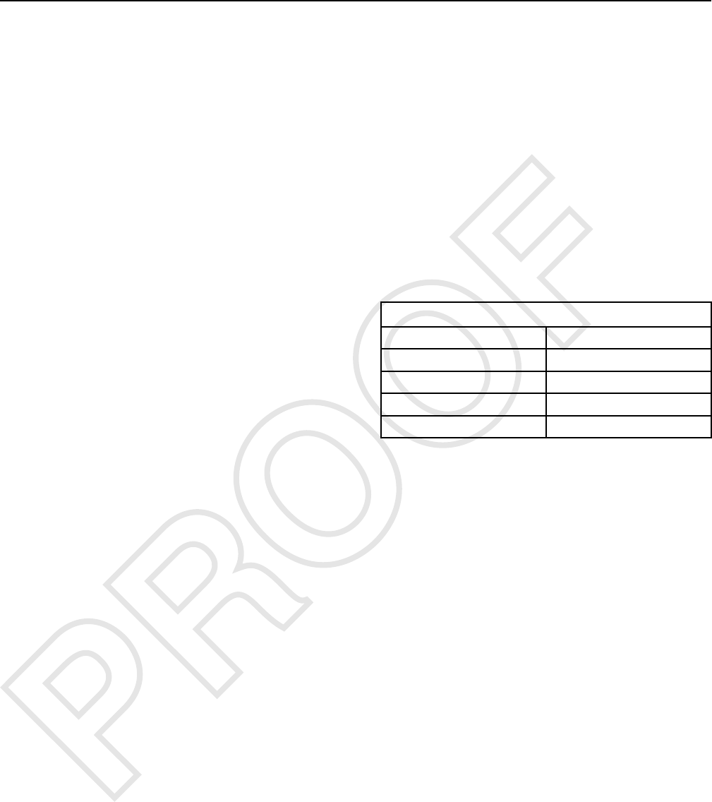
Status Indicator
Illustration 2 g01014891
Typical installation of the Status Indicator
(1) Status Indicator
The status of the MSS is displayed by the status
indicator in accordance with Table 2 . The operator
can use the status indicator to determine the status of
the system or for troubleshooting.
Table 2
Status Indicators(1) Description
Red The MSS is armed.(2)
Green The MSS is disarmed.
The green LED will remain ON 30 seconds after power down (Grace Period). After the 30 seconds
have passed, the MSS automatically returns to the “armed”mode.
(1) The LED's are illuminated during initial power-up in order to test the LED's.
(2) The red LED will remain ON while the key is in the ON position or until a valid key is read.
i06195462
Key Information
SMCS Code: 7631
You may configure the “Machine Security System ”
(MSS) to recognize up to 255 authorized keys. This
list contains those keys that will disarm the Machine
Security System. The user adds keys to this list.
Note: The system will be limited to 50 keys on older
machines. This limitation is due to software limitations
on the Machine ECM that utilizes a version of
software that does not support the larger key storage.
The ECM can store five configuration parameters that
identify each electronic key. These parameters are
listed below:
•“Security Type”
•“Description”
•“Access Level”
•“Expiration Date”
•“Security ID”
The parameters are not stored in the electronic key. A
complete list of the configuration parameters that are
available in the Caterpillar Electronic Technician
(ET) are listed below:
1. Add an electronic key.
2. Change the information that is related to the
electronic key.
a. Access level
8 UENR7000
Systems Operation Section

b. Expiration date
c. Description
3. Delete an electronic key.
4. “Security Bypass Times”
5. Set the internal clock.
6. “Fleet Configuration”
Note: Refer to the Testing and Adjusting, “Key -
Program” section for additional information on items
2.a., 2.b., 2.c., 3, 5, and 6. Refer to the Testing and
Adjusting, “Scheduled Access - Program” section
addition information on item 4.
Note: A single electronic key can be used on as
many machines with an MSS as desired. The
following parameters can be different on each
machine: Description, Access Level and Expiration
Date. The ID will be the same on all the machines
Note: The features of the MSS are supported in
version 2015A or later of the Caterpillar Electronic
Technician (ET).
Table 3
Security Type Description Access Level Expiration Security ID
Key Operator 1 Master “- - - - -”0:183243096
Key Operator 2 Standard “- - - - -”0:110105956
Passcode Operator 3 Standard “10/24/2016”245865321
Security ID
The ID that is stored in the electronic key is a 16-digit
number that is displayed as two 8-digit numbers in
the Caterpillar®Electronic Technician (ET). This field
is known as “Security ID”. When the numbers are
combined, the complete ID number is formed. The
ECM uses this ID to associate a key to the set of
parameters in the list of keys. Entries in the list may
have the same information for the following items:
Description, Access Level and Expiration Date. You
may choose a description of 11 characters or less for
each key in the list of keys. There can be multiple
entries in the list with the same description. Create a
description so that the key describes either the owner
of the key or the function of the user.
Passcodes are utilized on some machine in place of
electronic keys. This passcode will be a number
assigned to an operator to allow authorized operation
of the machine. Refer to the machine Operation and
Maintenance Manual for additional information.
Note: Duplicate descriptions for the electronic keys
are not advisable.
Access Level
You may assign one of two access levels to a key in
the list of keys. The levels are either “Standard”or
“Master”. Both access levels allow the key to disarm
the system for operation. The master access level
also gives the user the ability to modify the settings of
the Machine Security System with the Caterpillar
Electronic Technician (ET).
The standard access level is for normal operation of
the machine. The master access level should be
restricted to those persons that need to modify the
settings of the Machine Security System.
Security Type
The security type identifies the type of security
access that is being utilized. There are currently two
types of security identification.
• Key
• Passcode
UENR7000 9
Systems Operation Section
Expiration Date
An expiration date may be assigned to any key in the
list of keys. This expiration date is defined in 6 hour
intervals on a given date. The third entry in Table 3
contains an expiration date. For all of the other keys
in Table 3 , the column with the expiration date is filled
with “Dash lines”.“Dash lines”indicates that those
entries do not have an expiration date. The Machine
Security System has an internal clock. Once the
internal clock has passed the expiration date for a
key, that key will no longer disarm the system.
However, the entry will not be deleted from the list of
keys. A new expiration date can be set, or the feature
can be disabled. A possible use for the expiration
date is used with a rental contract.
Note: If the machine is running when the expiration
date and time are reached, the machine will continue
to run. When the machine is shut down and the 30
second grace period has timed out, the machine will
not be allowed to restart.
i06195480
Scheduled Access
(“Security System Bypass
Times”)
SMCS Code: 7631
The Machine Security System can be programmed to
disarm for a time period. The MSS can be set to
disarm for different time periods on each day. Within
these periods of time, any Caterpillar ®key (a
standard key or an electronic key) will operate the
machine.
Note: It is not possible to configure the ““bypass
times”” for an individual electronic key. The
““bypass times”” are not associated to an
individual electronic key.
“Security System Bypass Times”are time periods
that can be set to disarm the Machine Security
System automatically. An electronic key is not
required during these periods. This feature can be
used for the normal work shift of the machine.
Outside the normal work shift, the Machine Security
System would be armed. When the MSS is armed, an
electronic key is required to start the machine. This
feature would minimize the number of electronic keys
that are needed.
Table 4
“Sunday Security System Bypass Start Time”00:00
“Sunday Security System Bypass Stop Time”00:00
“Monday Security System Bypass Start Time”6:00
“Monday Security System Bypass Stop Time”18:00
“Tuesday Security System Bypass Start Time”6:00
(continued)
(Table 4, contd)
“Tuesday Security System Bypass Stop Time”18:00
“Wednesday Security System Bypass Start Time”6:00
“Wednesday Security System Bypass Stop Time”18:00
“Thursday Security System Bypass Start Time”6:00
“Thursday Security System Bypass Stop Time”18:00
“Friday Security System Bypass Start Time”6:00
“Friday Security System Bypass Stop Time”12:00
“Saturday Security System Bypass Start Time”12:00
“Saturday Security System Bypass Stop Time”12:00
Table 4 shows an example of “Security System
Bypass”. The “Start Time”is the time when the
Machine Security System will disarm. The Machine
Security System will return to the “armed”state at
the “Stop Time”. Between these two periods of time,
any Caterpillar ®key will operate the machine. Thus,
the MSS is disarmed during this time period.
All times are based on a 24 hour clock. For example,
6:00 am is 06:00 and 3:00 pm is 15:00. The Machine
Security System will be disarmed during the times
that are listed below: Monday through Thursday from
06:00 to 18:00
On Friday, the MSS is disarmed for only half of the
workday. After 12:00 on Friday, the Machine Security
System will be armed automatically. Operation will be
restricted to operators with electronic keys that are
authorized in the ECM on that machine. Refer to
Table 4 .
The Machine Security System is “armed”on the
weekend. Because the “Start Time”and the “Stop
Time”are set for the same time, the Machine
Security System will be armed throughout the day.
See Testing and Adjusting, “Scheduled Access -
Program” in order to program the security system
bypass times.
i06195486
Diagnostic Operation
SMCS Code: 7631
A diagnostic code indicates that the ECM has
detected one or more of the following conditions:
• an invalid signal from an input
• an improper feedback from an output
• an internal error
One method of displaying diagnostic information is
provided:
• Diagnostic codes with descriptive text can be
viewed with the Caterpillar Electronic Technician
(ET).
10 UENR7000
Systems Operation Section

Display the diagnostic code with the Caterpillar
Electronic Technician.
This method of displaying the diagnostic codes uses
the service tool to display the codes. The Component
Identifier (CID) identifies the specific component for a
specific diagnostic. The Failure Mode Identifier (FMI)
identifies the type of diagnostic that was detected.
The diagnostic codes allow consistent identification of
the problem. The service tool is used to display the
CID-FMI with descriptive text for each combination.
The descriptive text will help to avoid mistakes in
interpreting the codes.
Active Diagnostics
Active diagnostics indicate the presence of active
diagnostic codes for the MSS. A diagnostic code
informs the operator that a problem exists with the
MSS.
If the Cat service tool is available, the service tool
can be used to display all active diagnostic codes.
The service tool will also display codes that have
been logged.
Logged Diagnostics
A logged diagnostic will record problems that are
intermittent for the Machine Security System. Logged
diagnostics eliminate the need to duplicate problems
that are intermittent. Logged diagnostics will increase
the accuracy of diagnosis. The time that is required to
troubleshoot a problem is reduced with the use of
Diagnostics. Logged diagnostics eliminate the need
for trip recorders that are used to capture intermittent
diagnostic information.
The control module memory is used to store
diagnostic information. When a diagnostic is
detected, the following information is logged:
• The CID will identify the component that has failed.
• The FMI will describe the problem.
• Number of occurrences of the diagnostic code
• The time of the first occurrence that the diagnostic
was detected.
• Last occurrence time, when the diagnostic was last
detected (stored with both machine hours and
RTC stamp)
The problems which can be logged are listed in
Troubleshooting, “Diagnostic Code List”. Refer to the
Troubleshooting manual for your machine
The ECM logs the number of times that the machine
is started with the methods that are listed below:
• Starting using an unauthorized method
i06195511
Protected Functions
SMCS Code: 7631
There are two levels of protection for the machine
security system (MSS) :
• An electronic key with standard access level and a
non-electronic key
• An electronic key with master access level (factory
password)
The requirements for each level are explained below:
An Electronic Key with Standard Access Level
and a Non-electronic Key
• The table of the MSS keys can be viewed but the
table cannot be modified.
• The configuration settings of the MSS can be
viewed but the settings cannot be modified.
Electronic Key with Master Access Level
A factory password or a master access level is
needed to modify any MSS settings through the
service tool.
• The settings for the MSS can be modified.
• The list of valid key IDs can be modified.
i06195540
Service Operation Using
Service Tool
SMCS Code: 0785-UE; 7631
The service tool is used to communicate with the
ECM for the following information:
• display and control of code
• programming
• management
• diagnostics
To protect the machine properly, the service tool
requires a factory password or master access level
key, before modifications can be made to the MSS.
UENR7000 11
Systems Operation Section
i06195546
Electronic Control Module
(ECM)
SMCS Code: 7610-MCH
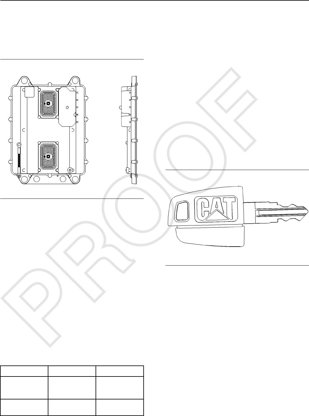
Illustration 3 g00785019
Electronic Control Module (ECM)
The Machine Security System (MSS) is an integrated
feature for the machine ECM. The MSS software and
components are integrated into an ECM that controls
other machine functions. The system may utilize up to
255 electronic keys.
Note: The system will be limited to 50 keys on older
machines. This limitation is due to software limitations
on the Machine ECM that utilizes a version of
software that does not support the larger key storage.
ECM Inputs
Keyswitch
The key start switch is also used as an input signal to
the MSS. The input from the key switch is used to
determine when the machine is on. Battery voltage is
connected to this input through the ON and START
positions of the keyswitch. See Table 5 for input
voltages.
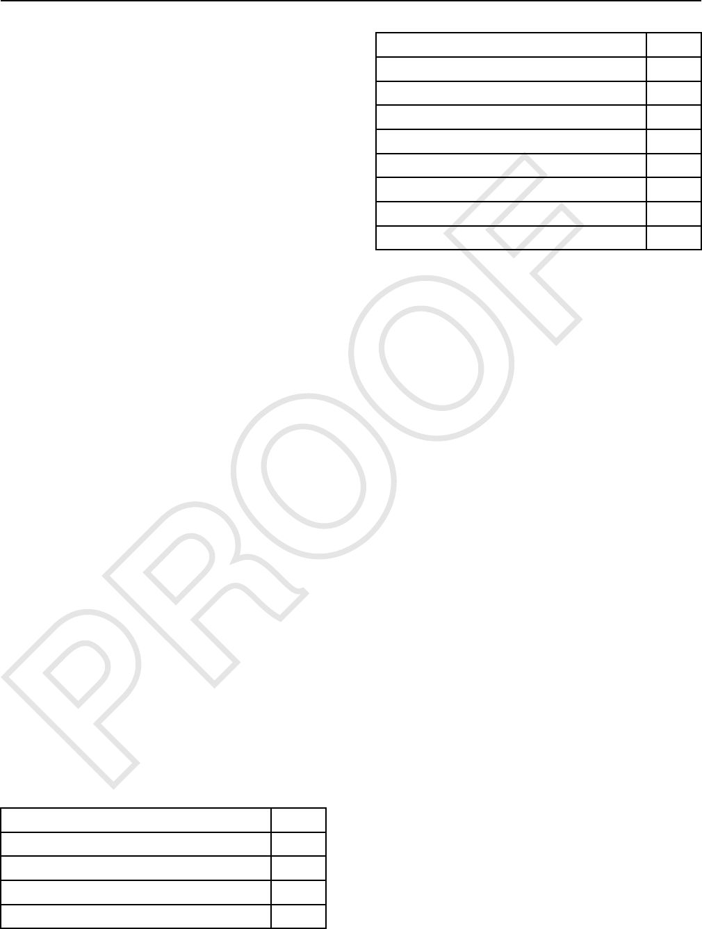
Table 5
Input Voltage 12V System 24V System
Machine is operating
and the alternator is
charging.
14.1 - 15.1V 27.6 - 29.6V
Machine is not
running.
12V 24V
ECM Outputs
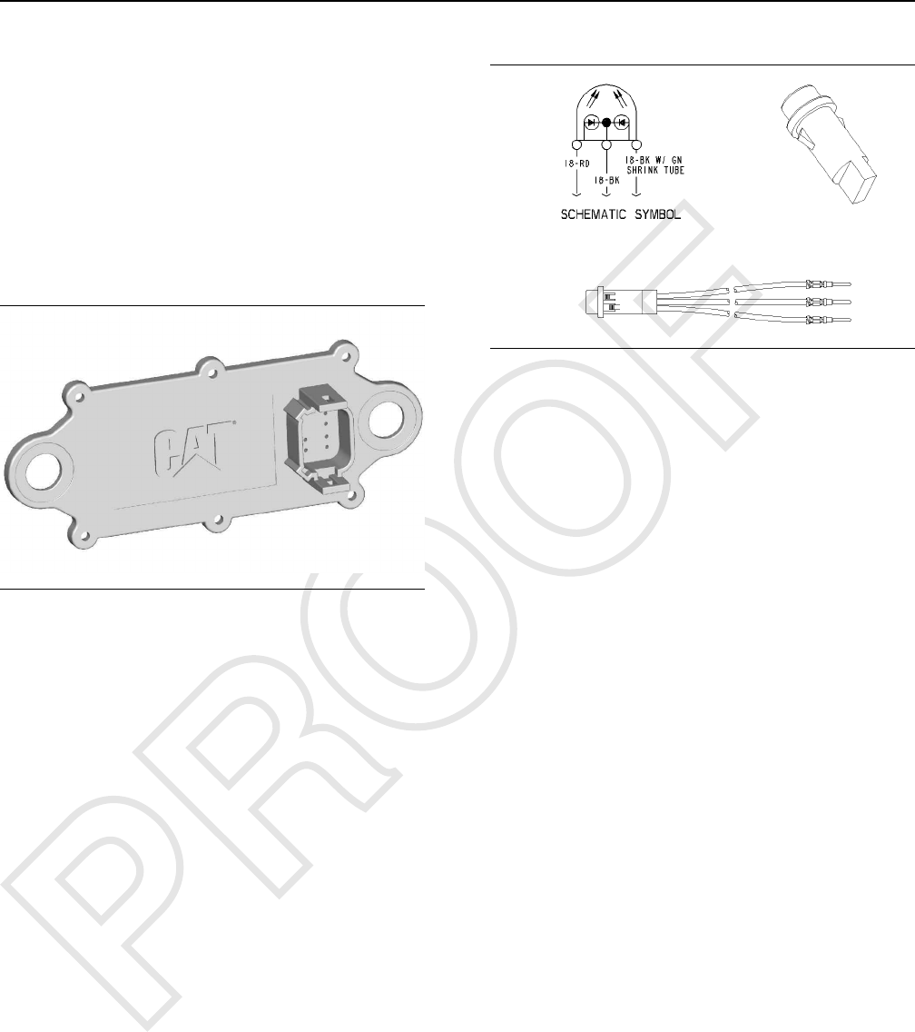
Status Indicator
The status indicator displays status of the system.
The status indicator has three connections. One of
the three connections is for a ground. Another
connection is for the red LED. The third connection is
for the green LED.
Output Drivers
Output drivers are available to control critical machine
functions. Unless a valid “key ID”has been identified
by the system, the drivers will remain without power.
i06195569
System Components
SMCS Code: 7631
Caterpillar ®Electronic Key
Illustration 4 g00793955
The Caterpillar Electronic Key
The electronic key has the same key cut as the
universal Caterpillar ®key. The electronic key has an
electronic chip that is embedded inside the head of
the key. The electronic keys are gray or yellow.
Exciter Coil
The exciter coil provides communication between the
electronic key and the key reader module.
The exciter coil is mounted around the keyswitch.
This position allows the exciter coil to communicate
with the electronic key. Any ferrous metal between
the coil and the electronic key will interfere with the
communications. Mounting the coil in the same plane
as the top of the key start switch will minimize the
interference.
Note: Ensure that you have only one electronic
key near the exciter coil when the MSS reads the
key. If there is more than one key, the ECM will not
be able to read the key and the machine will not
start.
12 UENR7000
Systems Operation Section
The exciter coil is connected to the harness via a 2-
pin connector and a length of wire.
Antitheft Keypad
The antitheft keypad, (if equipped), immobilizes the
engine, transmission, and hydraulic systems until a
valid passcode is entered.
Refer to the Machine Operation and Maintenance
Manual for details on the Anti Theft Keypad
operation.
Electronic Key Reader (MSS3i)
Illustration 5 g01007352
When the key start switch is placed in the ON
position, the ECM will send a signal over the CAN
data link. That signal will command the key reader to
excite the coil. The key ID from an electronic key is
sent back to the requesting ECM over the CAN data
link.
Note: The key reader is NOT designed to
communicate with the Caterpillar ®Electronic
Technician (Cat ®ET). However the key reader
control can be flashed via Cat ®ET. Refer to Test and
adjust section, “ECM Flash” section of this manual.
Status Indicator
Illustration 6 g00862013
The state of the MSS is displayed by the status
indicator. The green LED of the status indicator turns
ON when the system is disarmed. The machine
should start. The red LED of the status indicator turns
ON when the system is armed and an invalid
electronic key has been read by the MSS. The
machine should not start. The green LED and the red
LED will remain OFF when the machine security
system is not installed.
Note: The Status indicator may be located in the
dash cluster on some machine. Refer to the System
Operation Manual for more information on the dash
cluster.
i06195571
Data Link
SMCS Code: 7631
CAT Data Link
The Cat Data Link can connect the ECM for the
following items:
• Service tools
• Onboard controls
• Monitoring systems
The service tool can send information to the ECM
through the Cat Data Link. The ECM can provide
information over the Cat Data Link to the following
items: other electronic controls and service tool. The
information can be for diagnostics, or the information
can be used to control other systems on the machine.
UENR7000 13
Systems Operation Section

CAN Data Link
The CAN Data Link is an input and an output of the
machine ECM. The CAN Data Link is designed to
communicate with other electronic control modules
through the machine harness. The CAN Data Link
consists of internal ECM circuits and a twisted pair of
wires within the wire harness. The CAN Data Link is
bidirectional. The CAN Data Link allows the ECM to
receive and transmit information and the CAN Data
Link allows the ECM to send and receive information.
The CAN Data Link communicates at a faster rate
than the CAT Data Link.
The Electronic Key Reader (MSS3i) utilizes CAN data
link for flashing.
14 UENR7000
Systems Operation Section

Testing And Adjusting
Section
Testing and Adjusting
i06195575
General Information
SMCS Code: 7631
Caterpillar Electronic Key
The machine security system (MSS) uses a
Caterpillar Electronic key. The key contains an
electronic chip that is embedded in the head of the
key. This chip contains a unique identification
number. No two keys have the same ID. The
Electronic Key uses the same key cut as the standard
Caterpillar key. The electronic key can be used to
operate machines that are not equipped with the
MSS. The head of the electronic key is gray or yellow
in color.
A System Disarm Feature will allow a machine to
operate with any key. Refer to the Testing and
Adjusting, “Scheduled Access - Program” for
additional information.
Security Management
The Machine Security System uses the Caterpillar
Electronic Technician (ET), version 2015A or later, to
manage the settings of the system. There are
restrictions on accessing the settings. The “Security
Management”feature for the MSS controls the
access to the settings.
i06195578
Troubleshooting
SMCS Code: 7569
Refer to the Troubleshooting manual for your
machine in order to troubleshoot system failures.
i06195584
Key - Program
SMCS Code: 7631-591
The machine security system (MSS) may be
programmed to accommodate up to a maximum of
255 keys. A new key is programmed into the machine
ECM with the service tool.
Programming with a Service Tool
The “Security Management”function of the
Caterpillar ET allows you to view information on the
key currently in the key switch. You may also view a
list of authorized keys. The authorized keys are the
keys that have been programmed into the MSS.
UENR7000 15
Testing and Adjusting
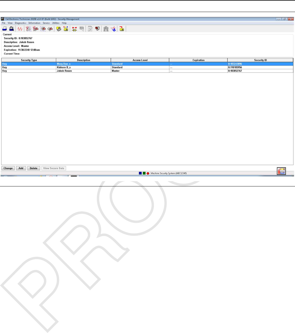
Illustration 7 g03858873
Security Management
Connect a laptop computer with the Caterpillar ET to
the machine that will be programmed. After the laptop
computer is connected to the machine, start the ET.
Select the machine that has the MSS installed. Select
the “Security Management”option from “Service”
menu. The “Security Management”screen will be
displayed. Refer to Illustration 7 .
Layout of the Screen
The “Security Management”screen has the
following areas:
““Current Key Information”” – The “Current Key
Information”area displays information of the key
currently in the keyswitch. If the “Description”,
“Access Level”and “Expiration”information was not
entered for the current key, these areas will be blank.
““Display Area”” – The “Security Management”
display area has five columns: “Security Type”,
“Description”,“Access Level”,“Expiration”and
“Security ID”. The information can be sorted by a
column. Click on the heading of the column, in order
to sort by the information in that column. The
“Description”column is the name for the key. The
“Access Level”column displays the access level for
the key. There are two access levels: Master and
Standard. The Master Access Level gives the user
the capability to add or change information without a
factory password. Standard Access Level requires
factory passwords to add information on keys. The
“Expiration”column gives the date and the time that
a key will expire. Keys expire in 6 hour increments.
“Security ID”is the unique identification numbers for
the key.
Push Buttons – The following push buttons are
available in the “Security Management”screen:
“Change”,“Add”and “Delete”.
16 UENR7000
Testing and Adjusting
Adding Key Information
Illustration 8 g03859338
Add key information
The “Add”push button allows you to add a key to the
list of Authorized Keys.
Note: When a function requires a factory password,
the “Enter Factory Passwords”box is displayed.
To add a key, perform the following steps:
Note: Adding Keys requires a key with the master
access level or a factory password.
1. Insert a master key for that machine in the key start
switch. Turn the key to the ON position. If a master
key is not used, then a factory password is
required.
Note: The MSS indicator should be green.
2. Turn the key to the OFF position.
Note: The MSS indicator should remain green.
3. Insert the new key into the key start switch. This
insertion must be done within 30 seconds of step
2. Turn the key to the ON position before the MSS
indicator turns off.
4. Connect a laptop computer with the Caterpillar
Electronic Technician to the ECM on the machine.
Select the “Add Security Information”from the
menu in the ET.
5. Select the “Security Management Option”under
the Service Menu in the ET.
6. Press the “Add”push button. The “Add Key
Information”dialog box is displayed.
7. Press the “Read”push button. ID1 and ID2 will be
filled with the information for the key that is in the
ignition.
Note: The “ID1”field may contain a “0”.
8. Enter the name for the key in the “Description”
box, if desired. The description may have up to 11
characters. If no description is entered, the
description will default to “Sec#”. The # sign
indicates a number. For example, “Sec1”,“Sec2”
,“Sec...”.
Note: Duplicate names for the keys in the list of keys
is not advisable.
9. Select the access level of the key from the
“Access Level”menu.
UENR7000 17
Testing and Adjusting

10. Select an “Expiration”button: “Disable”or
“Enable”
“Disable”does not have an “Expiration Date”. If
“Enable”is selected, enter the “Expiration Date”
and “Expiration Time”for that key.
Note: Setting a Key with “Master Level Access”to
the “Enable”status with an expiration date will cause
the Key with “Master Level Access”to expire. If the
“Master Level Access”Key expires, you will no
longer be able to use the key as a Master Level
Access Key.
11. Press the “OK”button in order to add the
information for the key. The “Are you sure?”box is
displayed. Press “OK”in order to add the key.
Press “Cancel”in order to exit the “Add Key
Information”dialog box without adding the
information. Press “Help”to open on-line help for
assistance.
18 UENR7000
Testing and Adjusting
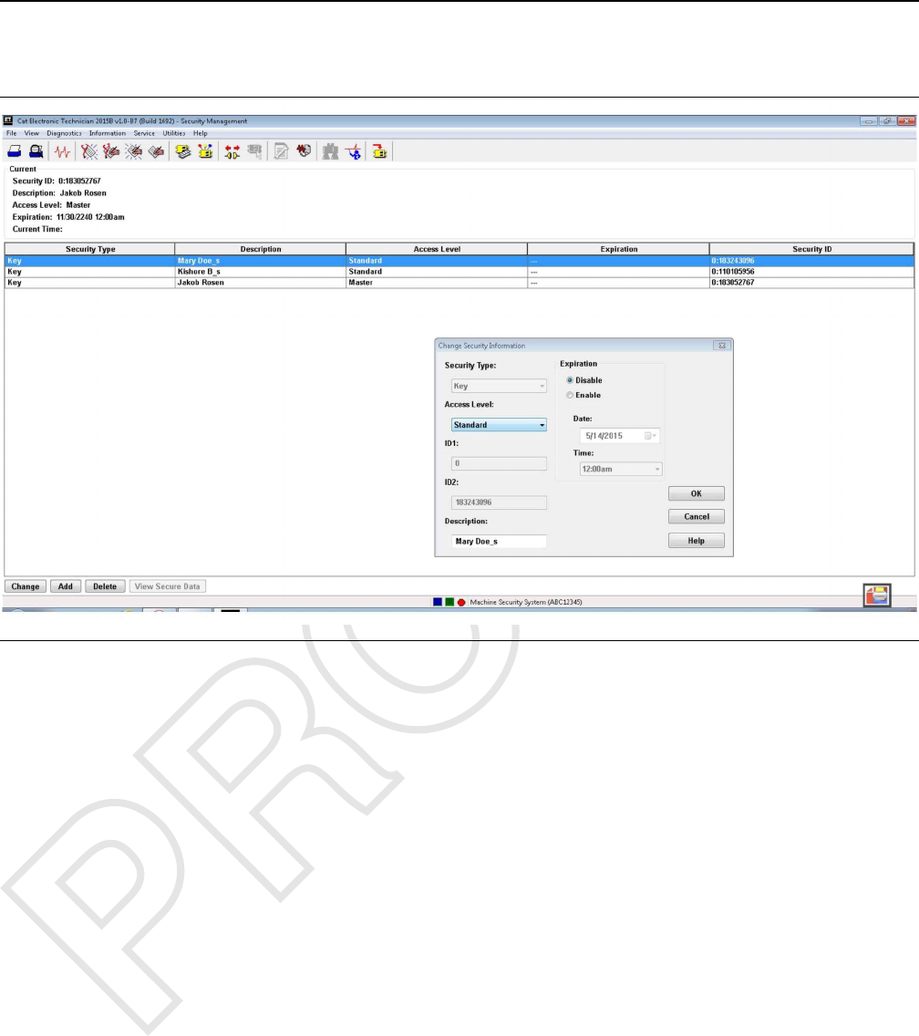
Changing the Key Information
Illustration 9 g03859364
Change key information
The “Change”push button allows you to change the
“Description”,“Access Level”or “Expiration”of a
key. ID1 and ID2 cannot be changed.
Note: The “Change”push button is disabled until a
key is selected from the authorized list.
Note: When a function requires a factory level
security password, the “Enter Factory Passwords”
dialog box is displayed.
Note: Changing Keys requires a key with the master
access level or a factory password.
Perform these steps in order to change the key
information:
1. Highlight the key that you want to change. Press
the “Change”push button. The “Change Key
Information”dialog box is displayed.
OR
Double click the key you want to change. The
“Change Key Information”dialog box is displayed.
2. Enter the changes you want to make. See “Adding
Key Information” for more detail.
UENR7000 19
Testing and Adjusting
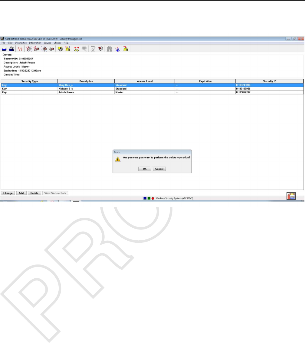
Deleting Key Information
Illustration 10 g03859371
Delete Key
Note: You cannot delete the last Master key. An error
message will display if you attempt to delete the last
master access level key.
Note: Deleting Keys requires a key with master
access level or a factory password.
To delete a key:
1. Highlight the key you want to delete. Press the
“Delete”push button. The “Are you sure?”box is
displayed.
2. Press “OK”if you want to delete the key. Press
“Cancel”if you do not want to delete the key. You
automatically return to the “Security Management”
screen.
20 UENR7000
Testing and Adjusting
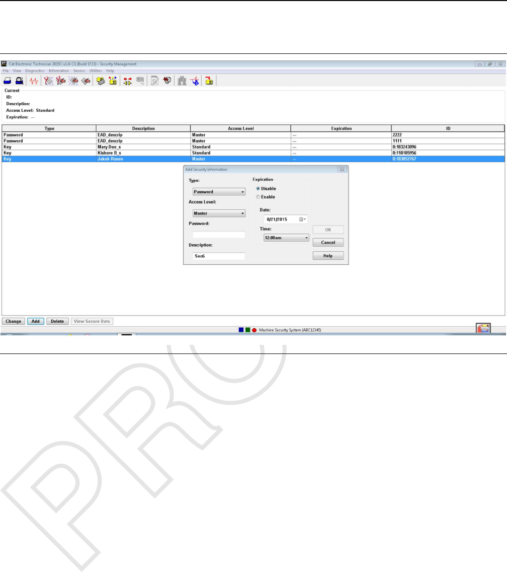
Adding A Password
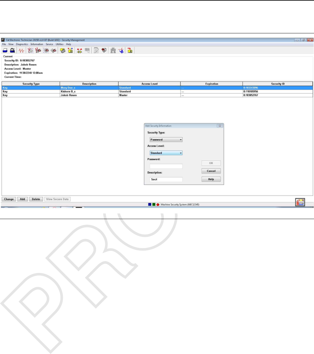
Illustration 11 g03882788
Note: Adding Passwords requires a key or password
with the master access level or a factory password.
1. Insert a master key for that machine in the key start
switch. Turn the key to the ON position. If a master
key is not used, then a factory password is
required. Alternatively a password entered through
the on-screen keypad with master access can be
used, if this feature is available on the machine.
2. Connect a laptop computer with the Caterpillar ®
Electronic Technician to the ECM on the machine.
Select the “Machine Security System”from the
menu in the Cat ®ET.
3. Select the “Security Management Option”under
the “Service Menu”in the ET.
4. Press the “Add”push button. The “Add Security
Information”dialog box is displayed.
5. Enter the desired password into the “Password”
box. Consult your User Manual for your machine
for password limitations.
Note: The “ID1”field may contain a “0”.
6. Enter the name for the password in the
“Description”box, if desired. The description may
have up to 11 characters. If no description is
entered, the description will default to “Sec#”. The
# sign indicates a number. For example, “Sec1”,
“Sec2”,“Sec...”.
Note: Duplicate names for the passwords in the list of
“Security IDs”is not advisable.
7. Select the access level of the password from the
“Access Level”menu.
8. Select an " “Expiration”button: “Disable”or
“Enable”.“Disable”does not have an “Expiration
Date”. If “Enable”is selected, enter the
“Expiration Date”and “Expiration Time”for that
password.
Note: Setting a password with “Master Level Access”
to the “Enable”status with an expiration date will
cause the password with “Master Level Access”to
expire. If the “Master Level Access”password
expires, you will no longer be able to use the
password as a Master Level Access password.
UENR7000 21
Testing and Adjusting

9. Press the “OK”button in order to add the
information for the password. The “Are you sure?”
box is displayed. Press “OK”in order to add the
password. Press “Cancel”in order to exit the
“Add Security Information”dialog box without
adding the information. Press “Help”to open on-
line help for assistance.
22 UENR7000
Testing and Adjusting
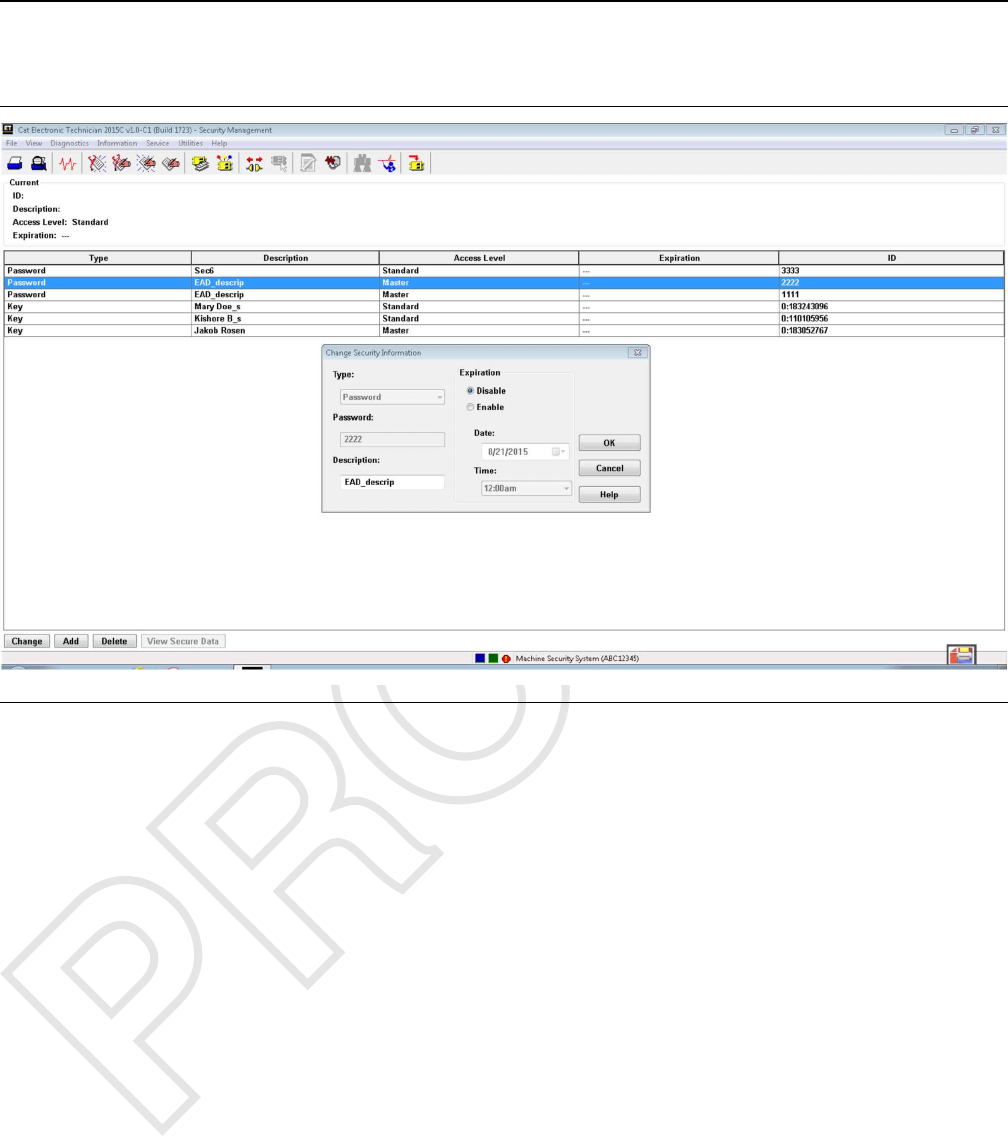
Changing A Password
Illustration 12 g03882805
Changing a Password
Note: Changing Passwords requires a key or
password with the master access level or a factory
password.
1. Insert a master key for that machine in the key start
switch. Turn the key to the ON position. If a master
key is not used, then a factory password is
required. Alternatively a password entered through
the on-screen keypad with master access can be
used, if this feature is available on the machine.
2. Connect a laptop computer with the Caterpillar ®
Electronic Technician to the ECM on the machine.
Select the “Machine Security System”from the
menu in the Cat ®ET.
3. Select the “Security Management Option”under
the “Service Menu”in the ET.
4. Press the “Change”push button. The “Change
Security Information”dialog box is displayed.
5. Enter the desired password into the “Password”
box. Consult your User Manual for your machine
for password limitations.
Note: The “ID1”field may contain a “0”.
6. Enter the name for the password in the
“Description”box, if desired. The description may
have up to 11 characters. If no description is
entered, the description will default to “Sec#”. The
# sign indicates a number. For example, “Sec1”,
“Sec2”,“Sec...”.
Note: Duplicate names for the passwords in the list of
“Security IDs”is not advisable.
7. Select the access level of the password from the
“Access Level”menu.
8. Select an " “Expiration”button: “Disable”or
“Enable”.“Disable”does not have an “Expiration
Date”. If “Enable”is selected, enter the
“Expiration Date”and “Expiration Time”for that
password.
Note: Setting a password with “Master Level Access”
to the “Enable”status with an expiration date will
cause the password with “Master Level Access”to
expire. If the “Master Level Access”password
expires, you will no longer be able to use the
password as a Master Level Access password.
UENR7000 23
Testing and Adjusting
9. Press the “OK”button in order to add the
information for the password. The “Are you sure?”
box is displayed. Press “OK”in order to add the
password. Press “Cancel”in order to exit the
“Add Security Information”dialog box without
adding the information. Press “Help”to open on-
line help for assistance.
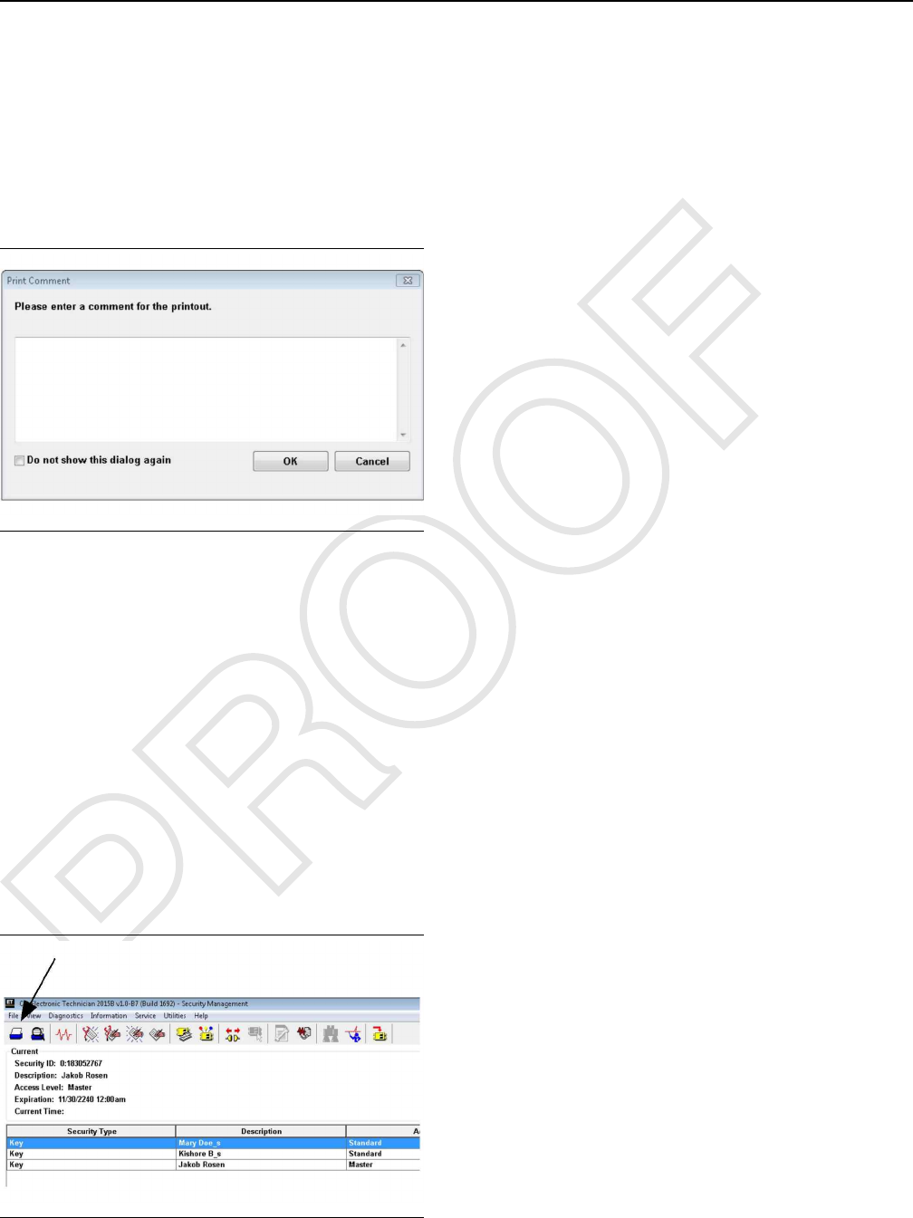
Printing Key Information
Illustration 13 g03859373
Print Dialog Box
The “Print Document”dialog box allows you to send
a report to a file, to a printer, or to the screen. The
report includes the following information:
• Source of data
• Time
• Date of report generation
• ECM connection
• List of parameter values
• Information that is unique to the function that you
are printing
To print a report to a file:
Illustration 14 g03878065
Print Icon On Tool Bar
1. Press the “Print Icon”in the upper left corner of
the tool bar. See Illustration 14 . The “Print
Document”box is displayed.
2. Press the “Print to File”button. Press “OK”in
order to print the report. Press “Cancel”in order to
exit the “Print Document”box without saving the
file.
Note: The “Printing”box asks you to open a file,
create a new file, or cancel, if you do not have a file
open. Choose the appropriate button in order to
continue.
Open: Press the “Open?”push button. The
“Open File Dialog”box is displayed. Highlight a file
and press the “Open”push button. The “Print
New Document To File”box is displayed.
New: Press the “New?”push button. Enter a new
file name into the “new file name”box. Press
“OK”. The “Print New Document To File”dialog
box is displayed.
Cancel: Press “Cancel”in order to exit the box.
You return to the “Print Document”box.
3. In the “Print New Document To File”, enter a name
for the document. Press “OK”. The “Print to File is
complete”box is displayed. Press “OK”in order
to return to the last active screen. Press “Cancel”
in order to exit the “Print New Document To File”
box.
To print a report to the printer:
1. Press the “Print Icon”in the upper left corner of
the tool bar. See Illustration 14 . The “Print
Document”dialog box is displayed.
2. Press the “Print to Printer”button and then press
“OK”. The “Print to Printer is Complete”box is
displayed. Press “OK”in order to return to the last
active screen. Press “Cancel”in order to exit the
“Print Document”box.
To print a report to the screen:
1. Press the “Print Icon”in the upper left corner of
the tool bar. See Illustration 14 . The “Print
Document”box is displayed.
24 UENR7000
Testing and Adjusting
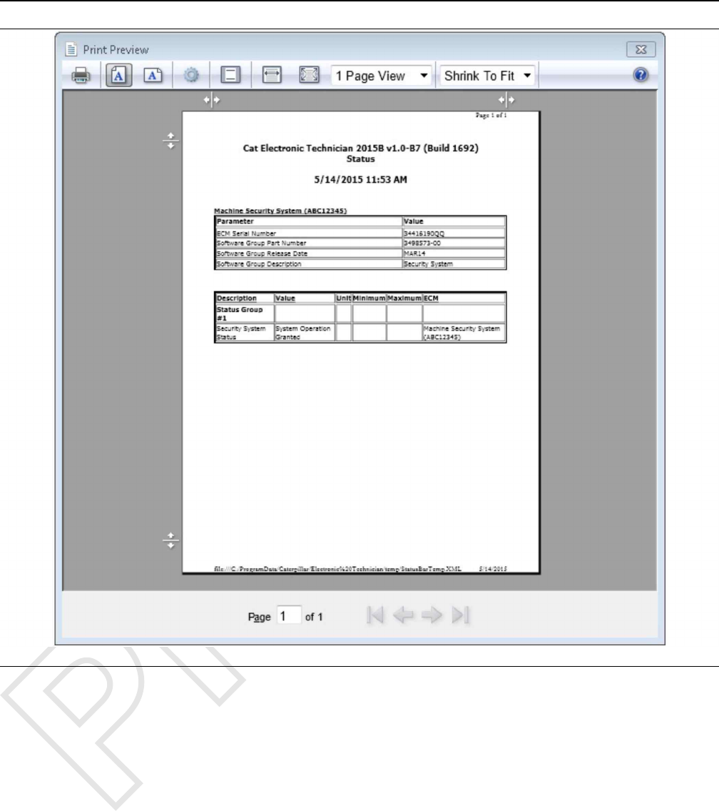
Illustration 15 g03859378
Typical ET screen for Security Management
2. Press the “Print Preview”button and then press
“OK”. The “Print Preview Screen”is displayed.
Choose the appropriate push button to aid in
viewing the document. “Print”prints the report to
the printer. “Next Page”views the next page of
the report. “Next Page”is disabled if you are on
the last page of the report. “Prev Page”views the
previous page of the report. “Prev Page”is
disabled if you are on the first page of the report.
“Two Page”displays two pages of the report.
“Zoom In”magnifies the text. “Zoom In”is
disabled when the text is fully magnified. “Zoom
Out”decreases the size of the text. “Zoom Out”is
disabled when the text is at normal size. “Close”
will exit the preview.
See Testing and Adjusting, “Configuration” in order to
copy and save key information to a file
i06195587
Scheduled Access - Program
(Security System Bypass)
SMCS Code: 7631-591
Use the following procedure to change the Activation
Periods of the Security System Bypass:
Note: Changing the MSS Bypass times requires you
to use a key with master access level or a factory
password.
UENR7000 25
Testing and Adjusting
1. Insert a key with Master Access Level in the key
start switch and turn to the ON position.
2. Select “Service/Configuration”from the tool bar of
the Cat ®ET. This selection will bring up the
Configuration screen.
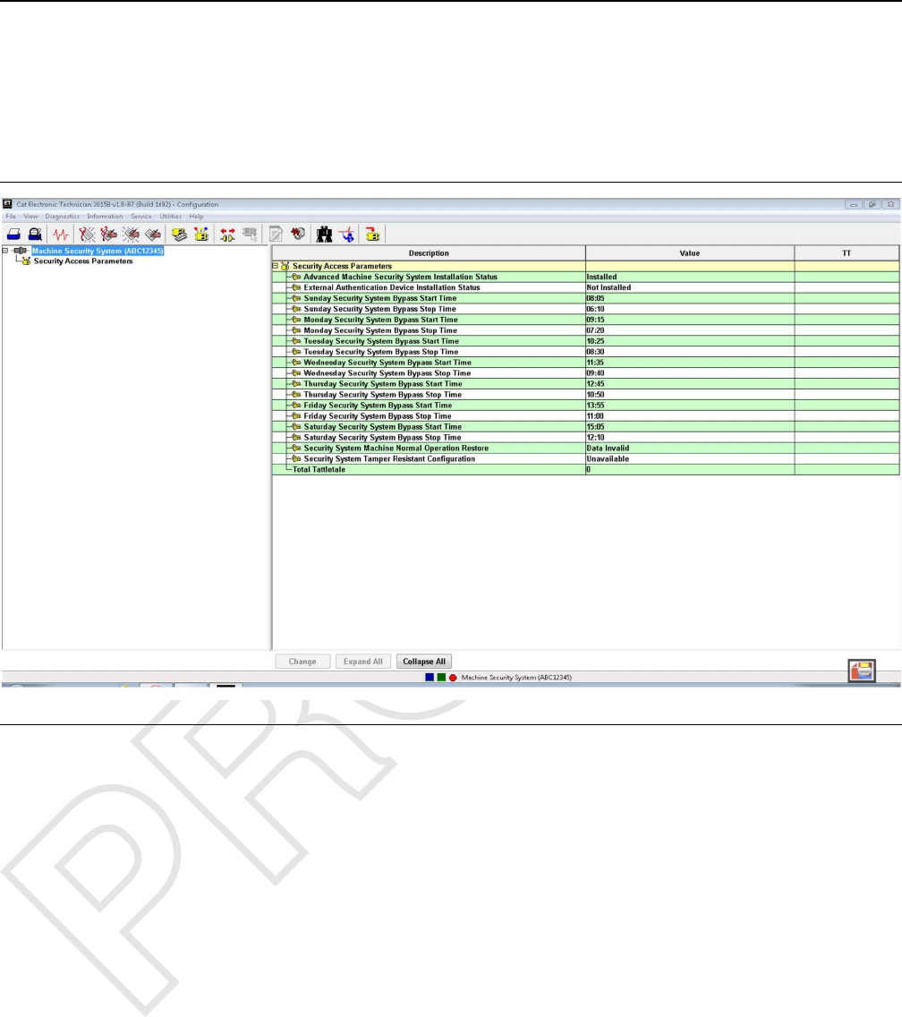
Illustration 16 g03859405
Typical ET screen
3. Highlight the “Security System Bypass Start Time”
for the day that you want to set up. Press the
“Change”push button at the bottom of the page.
This push button will bring up the “Change
Parameter Value”screen.
4. Enter the desired “start time”in the space that is
provided. Then click the “OK”button.
All times are based on a 24 hour clock. If you want
the desired start time to be 6:00 am, then enter
06:00. If you want the desired start time to be 6:00
pm, then enter 18:00. Include the colon in the time
setting or the MSS will not accept your entry.
5. Highlight the “Security System Bypass Stop Time”
for the same day. Press the “Change”push button
at the bottom of the page. This push button will
bring up the “Change Parameter Value”screen.
Enter the desired “stop time”in the space that is
provided and click the “OK”button.
6. Repeat Steps 3 and 5 for all days which should
have Bypass Activation Times.
7. To have the MSS armed 24 hours a day, repeat
Steps 3 and 5 entering 00:00 as the “Start time”
and 00:00 as the “Stop time”.
Note: All times are based on a 24 hour clock. Refer to
Testing and Adjusting, “Time - Set” for instructions on
setting the date and the time of the MSS.
i06195588
Time - Set
SMCS Code: 7631-529
Set the correct date and time for the Machine Security
System. Use the following procedure to set the date
and time.
Note: Changing the MSS clock time requires a key
with the master access level or a factory password.
When the 30 second grace period is active, the MSS
Status LED will be illuminated GREEN with the
keyswitch in the OFF position.
26 UENR7000
Testing and Adjusting
1. Connect the Cat ®ET to the service connector via
the communication adapter.
2. Place the Master Access Level Key into the key
start switch and turn the key to the ON position.
3. Start the Cat ®ET.
4. Click on the “Connect”icon in the menu bar of the
Cat ®ET.
5. Once the Cat ®ET has established
communications with the MSS ECM, select the
“ECM date/time”option from the “Service”menu.
This selection will cause the Cat ®ET to display
the following screen.
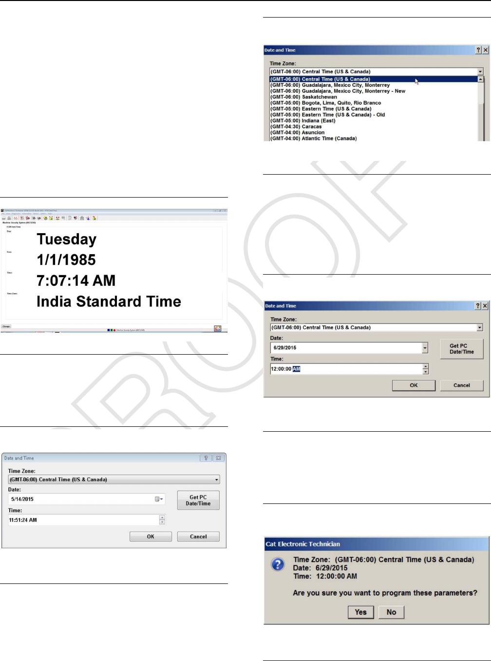
Illustration 17 g03859788
Date and Time
6. Press the “Change”button. This button will cause
the “Date and Time”dialog box.
Illustration 18 g03859826
Time Zone
7. Select the local time zone from the drop-down list.
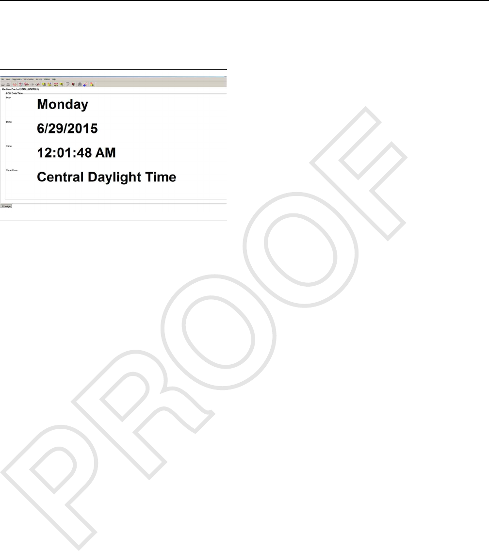
Illustration 19 g03859831
Local Date and Time
8. Enter the local date and time. Use an accurate time
source.
Note: Laptop clocks are not accurate and may have a
different time than the local time.
Illustration 20 g03859850
ET Display
9. Then press the “OK”button. The Cat ®ET will
display the following message.
Illustration 21 g03859865
Cat ET Time Confirmation
UENR7000 27
Testing and Adjusting
10. Click on the “Yes”button in order to change the
date and time or click on the “No”button in order
to cancel the change. The Cat ®ET will display the
new time on a 24-hour clock.
Illustration 22 g03859883
Cat ET Display 24 Hour Clock
i06195590
Factory Password - Obtain
SMCS Code: 7631-554-XW
You may use the following methods to obtain a
factory password. The first method is via the Feature
Protection System (FPS) via the Internet. The second
method is via the telephone help line. The procedures
for both methods are listed in the following sections.
Internet
1. The Feature Protection System (FPS) is a secure
web site and a password is required. Proceed to
step 1.a. if you do not have a “Login ID”and a
“Password”. Proceed to step 2 if you already have
a“Login ID”and a “Password”.
a. Refer to the “Telephone Help Line” section or
see your Caterpillar dealer in order to obtain
the factory password.
2. Open your web browser. Enter the address for the
Factory Password System (FPS) (“http://fps.cat.
com”) in the address bar of the web browser.
Upon accessing FPS, the “Corporate Web
Security”web site will appear.
28 UENR7000
Testing and Adjusting
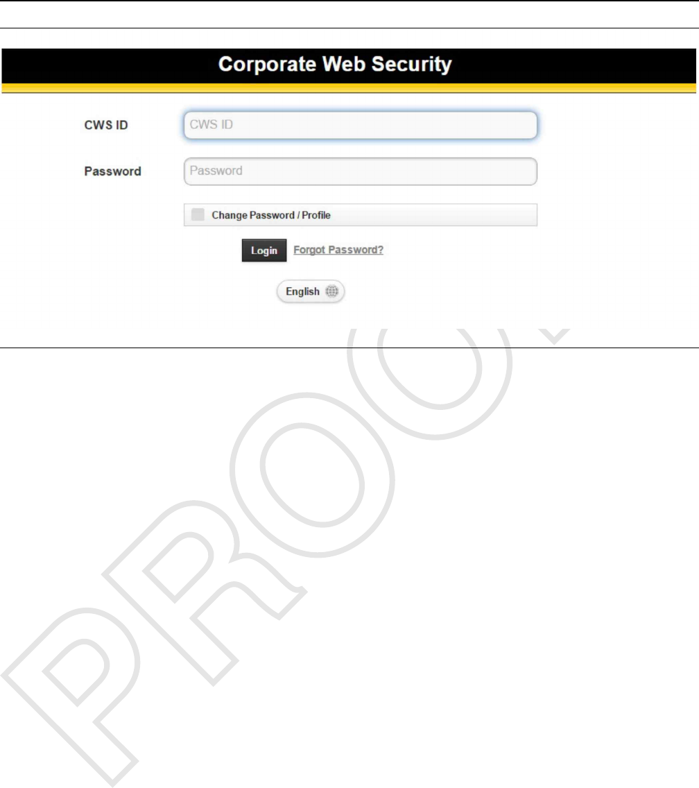
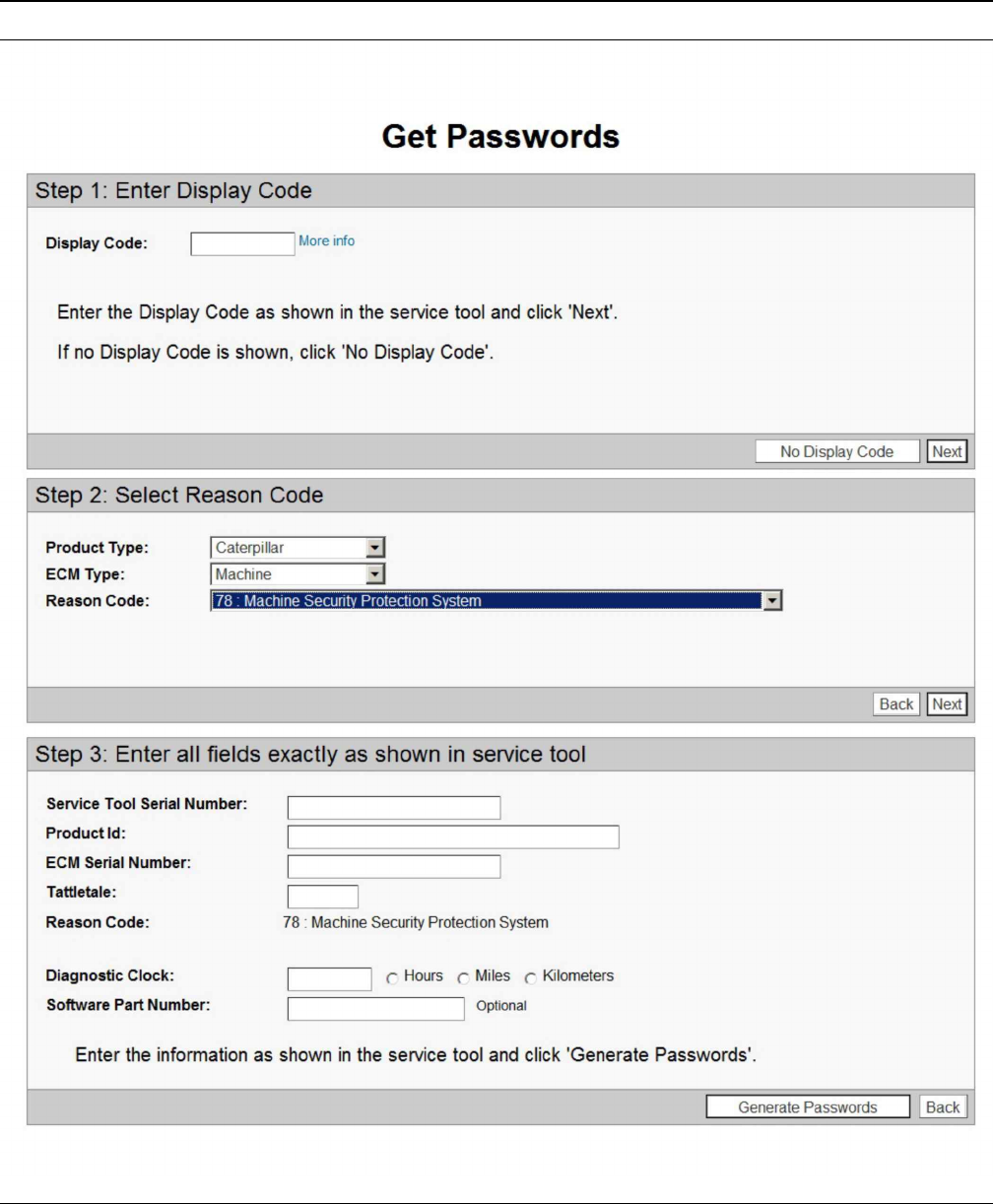
Illustration 24 g03859954
Product Serial Number
4. Enter the following information:
•“Product Serial Number”
•“Engine Units”
Note: Enter the hours that are displayed on the
service hour meter in the “Engine Units”block.
Select “Hours”as the unit.
•“Service Tool Serial Number”
30 UENR7000
Testing and Adjusting
•“ECM Serial Number”
•“Total Tattletale Value”
•“Reason Code”
Note: The “Rerate”section is not used with the
Machine Security System. Do NOT enter information
in this section.
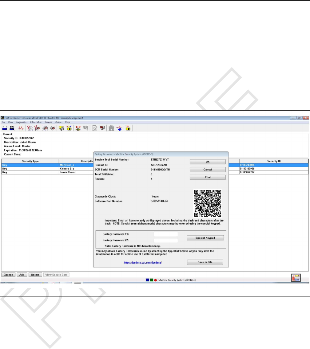
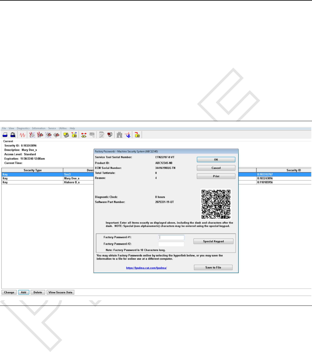
Note: The information that is listed above may be
obtained from the “Enter Factory Passwords”screen
in the Caterpillar Electronic Technician (ET). Refer to
Illustration 25 .
Illustration 25 g03859962
Factory Password
UENR7000 31
Testing and Adjusting

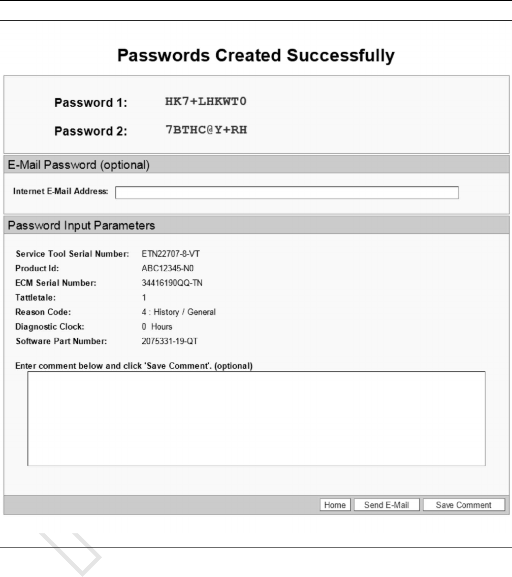
Illustration 27 g03879847
Factory Password Screen
6. Record both of the factory passwords.
Note: Both passwords are required, in order to
change any parameters of the Machine Security
System.
Telephone Help Line
The telephone help line for factory passwords is
available at the telephone number that is listed below:
(309) 636-8500
Note: (309) 636-8500 is also the telephone number
for the Dealer Solutions Network (DSN).
The telephone help line will need the information that
is listed in order to obtain the password:
UENR7000 33
Testing and Adjusting
•“Product Serial Number”
• Service Meter Hours ( “Engine Unit Block”)
• Serial number of the Service Tool (Electronic
Technician)
• Serial Number of the Machine ECM
• Total Tattletale Value
• Reason Code
Note: The information that is listed “Telephone Help
Line” may be obtained from the “Enter Factory
Passwords”screen in the Caterpillar ®Electronic
Technician (ET). Refer to Illustration 27 .
Illustration 28 g03864337
i06195595
Configuration
SMCS Code: 7631-025
““Fleet/Key Configuration””
The “Fleet/Key Configuration”function allows you to
configure and manage a Machine Security System
(MSS) enabled machine or a set of machines. The
function allows you to program, load, and save a set
of configuration parameters and key information. The
information can be loaded from or programmed to the
MSS. This information can also be saved to or loaded
from a file.
Once a file is saved in “Fleet/Key Configuration”, File
Management can be used to export the file as a *.
MSS file. The exported *.MSS file can then be
imported into the MSS Key Management Software
program, for management of the “Fleet/Key”
information.
Loading Data from the ECM
1. Connect the service tool to the Machine Security
System ECM that you want to copy.
2. Select “Copy Configuration”from the “Service”
menu, and then select “Fleet/Key Configuration”
from the submenu.
34 UENR7000
Testing and Adjusting

Note: Changing the “Fleet/Key Configuration”
requires a key with master access level or a factory
password.
3. If there is no recently loaded data available, the
“No data is available...”message box will display.
4. Press “Yes”to load data from the ECM. The
“ECM Selector”dialog box displays.
Press “No”if you do not want to load data. The
“Fleet/Key Configuration blank screen”displays.
Note: Pressing the “Load from ECM”push button
from the “Fleet/Key Configuration”screen also
displays the “ECM Selector”dialog box.
5. Highlight the Machine Security System ECM you
wish to copy from and then press “OK”. As the
data is loading from the ECM, the “Please wait”
message displays. Then, the “Loading data from
ECM”progress bar displays.
6. Press “Cancel”to exit the “ECM Selector”dialog
box. Press “Help”to open online help for
assistance.
You can cancel the loading process at any time, by
pressing the “Cancel”push button. The “Are you
sure...”message box displays. Press “Yes”to
cancel loading the data or press “No”not to
cancel loading the data.
7. When the data has been successfully loaded, “The
data has been successfully loaded”message box
displays.
8. Press “OK”. The “Fleet/Key Configuration”
screen displays with the “Program ECM”and the
“Save to File”push buttons are enabled.
Note: The data must be saved to a file before you
disconnect from the service tool or the data is lost.
Saving the Configuration to a File
1. Press the “Save to File”push button. The “Print
New Document to File”dialog box displays.
Note: If you do not have a file open, the “Printing”
dialog box asks you to open a file, create a new file,
or cancel. Choose the appropriate button to continue.
UENR7000 35
Testing and Adjusting
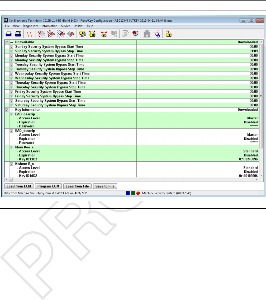
Illustration 29 g03864372
Saving Configuration to a File
2. Enter a document name and description in the
appropriate text boxes. Press the “OK”button.
The “Fleet/Key Configuration saved successfully”
message box displays. Press the “Cancel”push
button to exit the “Print New Document To File”
dialog box without saving the file. You will return to
the “Fleet Configuration”dialog box.
3. Press “OK”to return to the “Fleet/Key
Configuration”screen.
Loading Data from a File
1. Connect the service tool to the ECM to be
programmed.
2. Select “Copy Configuration”from the “Service”
menu, and then select “Fleet/Key Configuration”
from the submenu.
If there is no recently loaded data available, the
“No data is available...”message box displays.
3. Press “No”that you do not want to load data from
the ECM. The “Fleet/Key Configuration screen”
displays.
4. Press the “Load from File”push button. The “File
Management”dialog box displays.
5. If the “Load from File”push button is pressed with
unsaved data on the “Fleet/Key Configuration”
screen, a message box displays asking if you want
to save changes.
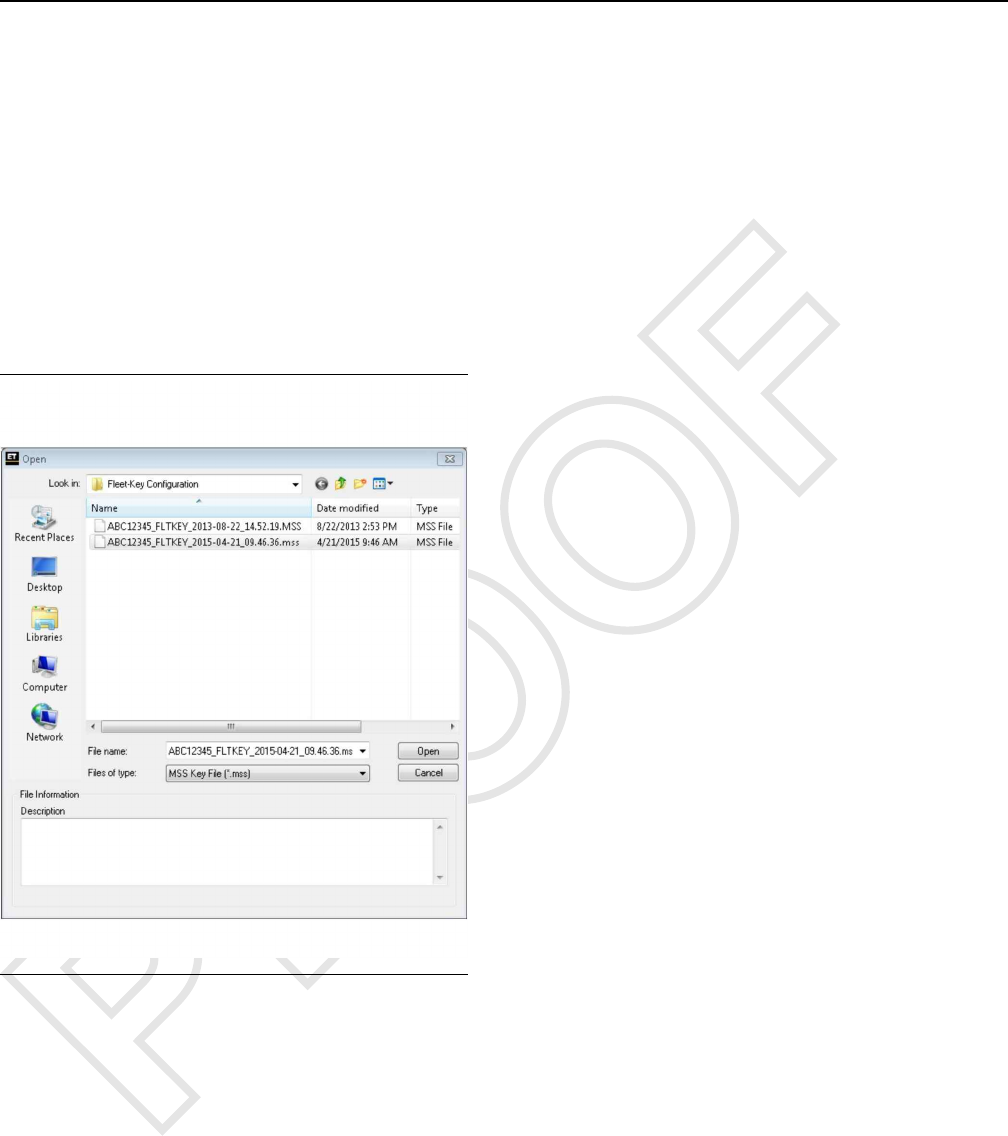
6. From the “File Management”dialog box, highlight
the file from the “Files”list box. Next highlight the
“Fleet/Key Configuration document”that you want
to load from the “Documents”list box.
7. Open the document. As the data loads, a progress
bar displays. Then, the “Fleet Configuration”
message box displays.
8. Press “OK”. The “Fleet/Key Configuration”
screen displays with the file data.
36 UENR7000
Testing and Adjusting
Programming the ECM
Note: The data must be loaded from a file before you
can program an ECM.
Note: Keys that are already programmed into the
ECM can be unchecked from the “Fleet/Key
Configuration”screen. This unchecking method is
only a time saving measure. If you do not uncheck
the keys, the “Program ECM”message box
displays. This message box lists all keys that were
not programmed because the keys were already
stored.
Press the “Program ECM”push button. The “ECM
Selector”dialog box displays.
Illustration 30 g03860018
ECM Selector dialog box
Highlight an ECM and press “OK”The “Please wait”
message box displays. Then the “Testing ECM”
progress bar displays.
You can cancel the uploading process at any time, by
pressing the “Cancel”push button. The “Are you
sure...”message box displays. Press “Yes”to
cancel uploading the data or “No”not to cancel.
Refer to the following procedures when you
“Append”or “Replace”the key list. Refer to the
“Append” section to append the list. Refer to the
“Replace” section to replace the list.
Append
1. Connect the service tool to the ECM to be
programmed.
2. Start the Caterpillar Electronic Technician (ET)
Note: This procedure requires Caterpillar Electronic
Technician (ET) version 2002A or later.
UENR7000 37
Testing and Adjusting
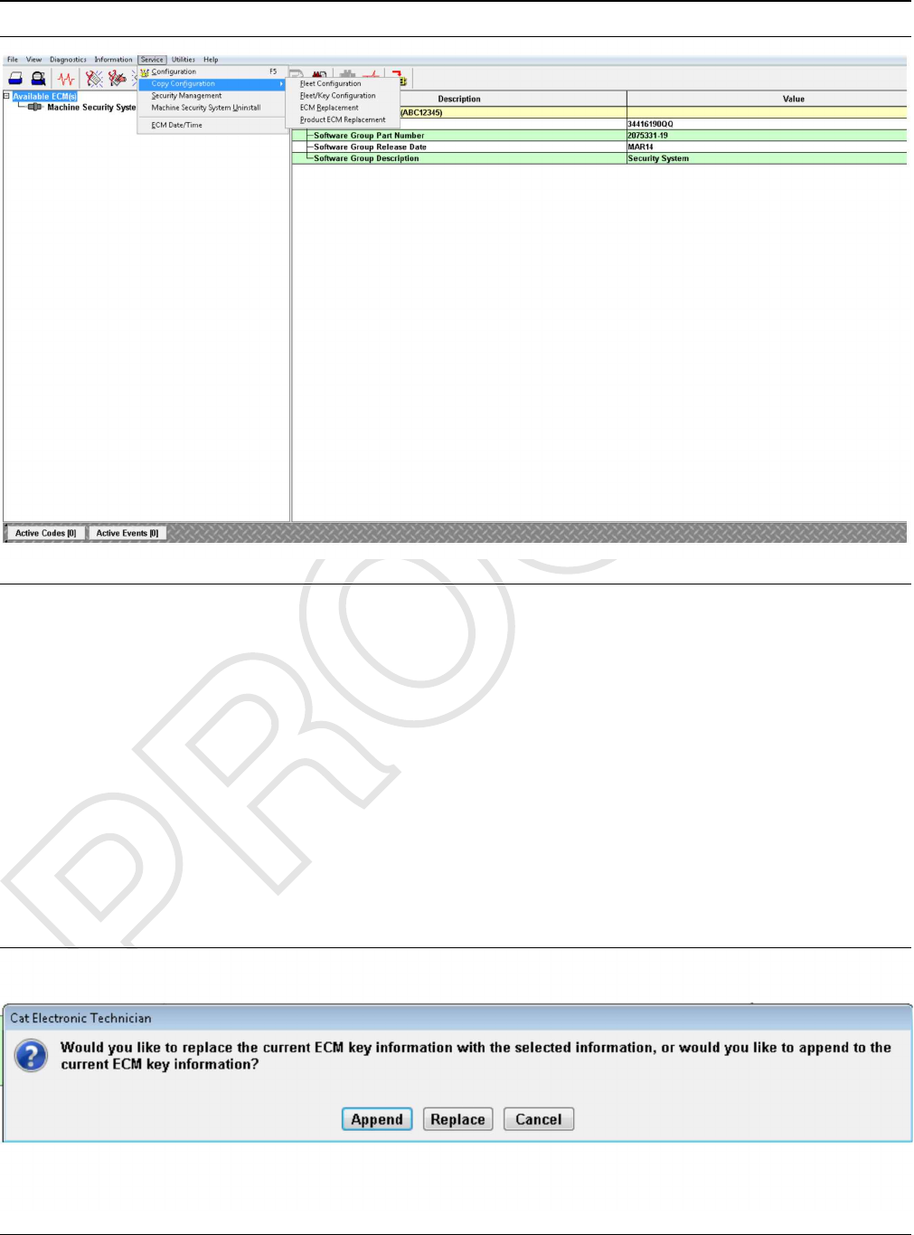
Illustration 31 g03864388
Copy Configuration, Service Menu, Fleet/Key Configuration
3. Select “Copy Configuration”from the “Service”
menu, and then select “Fleet/Key Configuration”
from the submenu.
4. Open the document. As the data loads, a progress
bar displays. Then, the “Fleet Configuration”
message box displays.
5. Press “OK”. The “Fleet/Key Configuration”
screen displays with the file data.
6. Click on the “Program ECM”button. This button
displays the Fleet key information box.
Illustration 32 g03864392
Append
38 UENR7000
Testing and Adjusting
7. Click on the “Append”button.
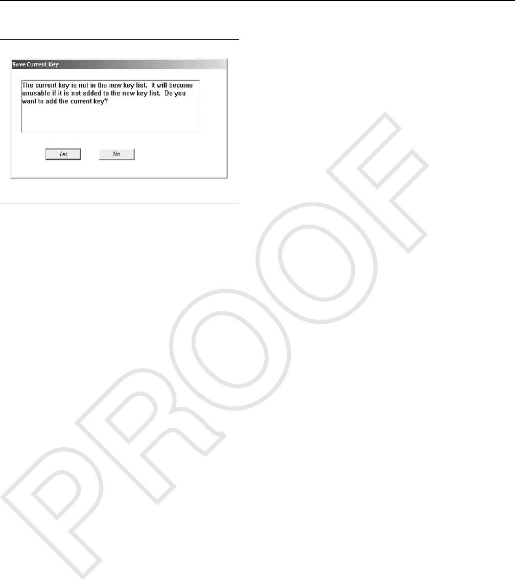
Illustration 33 g00900409
8. Click on the “Yes”button if you are prompted.
When the data has been successfully uploaded, the
“Programming complete.”message box displays.
Press “OK”
Note: MSS can store a maximum number of 50 keys
at one time. “Fleet/Key Configuration”determines
the number of keys slots not programmed on the
MSS. You cannot program more keys than the
maximum number allowed. A message box displays
informing you of the number of key slots available or
that there are no more key slots are available.
Remove enough keys in order to add new key
information.
STOP.
Replace
1. Connect the service tool to the ECM to be
programmed.
Note: This procedure requires Caterpillar Electronic
Technician (ET) version 2015A or later.
2. Start the Caterpillar Electronic Technician (ET)
UENR7000 39
Testing and Adjusting
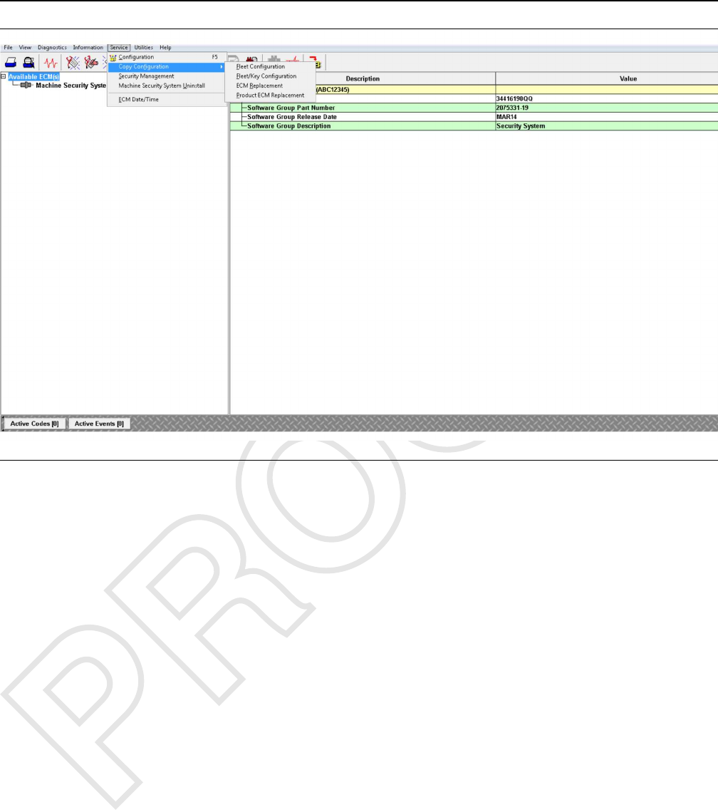
Illustration 34 g03864422
Copy Configuration, Service Menu
3. Select “Copy Configuration”from the “Service”
menu, and then select “Fleet/Key Configuration”
from the submenu.
4. From the “File Management”dialog box, highlight
the file from the “Files”list box. Next highlight the
“Fleet/Key Configuration document”that you want
to load from the “Documents”list box.
5. Open the document. As the data loads, a progress
bar displays. Then, the “Fleet Configuration”
message box displays.
6. Press “OK”. The “Fleet/Key Configuration”
screen displays with the file data.
7. Click on the “Program ECM”button. The Fleet
40 UENR7000
Testing and Adjusting
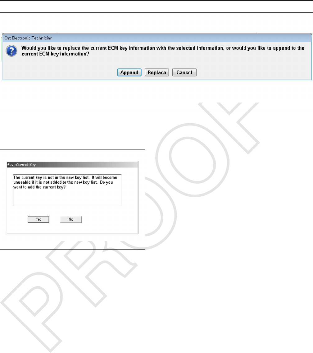
Illustration 35 g03864431
Replace
8. Click on the “Replace”button.
Illustration 36 g00900409
9. Click on the “No”button if you are prompted.
When the data has been successfully uploaded, the
“Programming complete.”message box displays.
Press “OK”
Note: MSS can store a maximum number of 50 keys
at one time. “Fleet/Key Configuration”determines
the number of keys slots not programmed on the
MSS. You cannot program more keys than the
maximum number allowed. A message box displays
informing you of the number of key slots available or
that there are no more key slots are available.
Remove enough keys in order to add new key
information.
STOP.
i06195599
Machine Security System -
Uninstall
SMCS Code: 7631-011
Use the following procedure in order to uninstall the
Machine Security System (MSS) permanently.
Note: You will need to obtain a factory password in
order to perform this procedure. A master electronic
key will not allow the user to uninstall the Machine
Security System. Refer to the Testing and Adjusting,
“Factory Password - Obtain” section of this manual
for information on obtaining a factory password.
Note: One factory password is required in order to
uninstall MSS premium software from the ECM that
the software is integrated with.
Note: An alternative to uninstalling the MSS software
is to use a master key in order to bypass the security
system. Refer to the Testing and Adjusting,
“Scheduled Access - Program”.
1. Connect a laptop Computer with the Caterpillar ®
ET to the machine via the communication adapter.
2. Place a key in the key start switch.
3. Turn the key to the “ON”position.
4. Start the Electronic Technician and establish
communications with the machine MSS3i ECM.
5. Select “Service/Configuration”from the toolbar on
the Cat ®ET. This selection will bring up the
configuration screen.
6. Highlight the “Machine Security System
Installation Status”and select the “Change”
button at the bottom of the page. This button will
bring up the “Enter Factory Password Screen”.
UENR7000 41
Testing and Adjusting

7. Obtain a factory password. Refer to the Testing
and Adjusting, “Factory Password - Obtain” section
of this manual for information on obtaining a
factory password.
8. Change the value to “Not Installed”.
9. Remove the electronic key reader hardware and
plug the connector.
i06195606
Glossary of Terms
SMCS Code: 7631
Armed – The state of the security system when the
machine is disabled.
CAN Data Link (CAN) – The CAN data link is an
electrical connection for communication with onboard
devices.
Disarmed – The state of the security system when
the machine is able to operate normally.
Electronic Control Module – The portion of the MSS
that contains the microprocessor and memory
Electronic Key Reader – The electronic key reader
module sends key information to the ECM. The
information is transmitted from the exciter coil to the
key reader module.
EID – Event Identifier
Exciter Coil – The exciter coil is a small coil of fine
wire. The wire is molded into the bezel of a keyswitch
with harness wiring. The exciter coil provides a path
of communication. The electronic key and the
electronic control module communicate via radio
frequency.
Factory Password – Protects the machine when
using the service tool. The password must be used
when any modifications are done to the MSS.
Immobilizer – The Machine Security System
Immobilizer is a feature within another ECM (Engine
and/or Transmission). This feature restricts the
operation of the machine until the Machine Security
System disarms.
Master Access Level – A level of access to permit
the operation of the machine. In addition, the key
allows the user to add new keys into the ECM and
allows MSS settings to be modified without a factory
password. Also, keys that are already programmed
can be modified.
MSS – Machine Security System
PID – A parameter identifier is used to identify
specific parameters that are used by the MSS.
Product ID – The Product ID is an 8 digit
alphanumeric number that identifies the machine.
Programming – Programming refers to the process
of storing information in the memory of the control
module.
Software Enable Attachment – A feature or function
on a machine that uses software in order to enable
the functionality. The actual software used to
accomplish the function is embedded in the standard
machine software (flash file). The feature requires a
factory level password in order to activate.
Standard Access Level – Keys that are
programmed for this level of access permit the
operation of the machine.
Tattletale – The tattletale is a counter in the ECM that
is used as part of the calculation for the factory
password. The tattletale is incremented after a factory
password is used. The affected parameter will have
an increase in the specific parameter of the tattletale
and the total tattletale will reflect the increase as well.
Once you use the factory password, the factory
password will no longer be valid. To make a change
on the same ECM at a later date, another password
will be required.
i06195610
System Schematic
SMCS Code: 7566
Refer to the corresponding schematic of the machine
or Special Instruction.
42 UENR7000
Testing and Adjusting

UENR7000 43
Index Section
Index
C
Configuration ................................................... 34
“Fleet/Key Configuration”............................ 34
D
Data Link.......................................................... 13
CAN Data Link ............................................. 14
CAT Data Link .............................................. 13
Diagnostic Operation....................................... 10
Active Diagnostics ........................................11
Logged Diagnostics ......................................11
E
Electronic Control Module (ECM) .................... 12
ECM Inputs .................................................. 12
ECM Outputs ............................................... 12
F
Factory Password - Obtain .............................. 28
Internet......................................................... 28
Telephone Help Line .................................... 33
G
General Information......................................4, 15
Glossary of Terms............................................ 42
I
Important Safety Information ............................. 2
K
Key - Program.................................................. 15
Programming with a Service Tool ................ 15
Key Information.................................................. 8
Access Level.................................................. 9
Expiration Date ............................................ 10
Security Type ................................................. 9
M
Machine Security System - Uninstall............... 41
N
Normal Operation .............................................. 6
Armed ............................................................ 7
Disarmed........................................................ 7
Electronic Key ................................................ 7
External Authentication Device (EAD) and
Pass Codes.................................................. 7
Reading the ID of a Key ................................. 6
O
Operation of Status Indicator............................. 7
Status Indicator.............................................. 8
P
Protected Functions..........................................11
S
Scheduled Access - Program (Security
System Bypass)............................................. 25
Scheduled Access ( “Security System
Bypass Times”) ............................................. 10
Service Operation Using Service Tool ..............11
System Components ....................................... 12
Antitheft Keypad........................................... 13
Caterpillar ®Electronic Key ......................... 12
Electronic Key Reader (MSS3i) ................... 13
Exciter Coil................................................... 12
Status Indicator............................................ 13
System Overview............................................... 5
System Schematic........................................... 42
Systems Operation Section............................... 4
T
Table of Contents............................................... 3
Testing and Adjusting ...................................... 15
Testing and Adjusting Section ......................... 15
Time - Set ........................................................ 26
Troubleshooting............................................... 15

©2015 Caterpillar
All Rights Reserved
CAT, CATERPILLAR, their respective logos, “Caterpillar Yellow”, and the POWER EDGE trade
dress as well as corporate and product identity used herein, are trademarks of Caterpillar and
may not be used without permission.