Caterpillar MSS3S Caterpillar MSS3s RFID Key Reader Module User Manual Exhibit D Users Manual per 2 1033 b3
Caterpillar, Inc. Caterpillar MSS3s RFID Key Reader Module Exhibit D Users Manual per 2 1033 b3
Exhibit D Users Manual per 2 1033 b3

SAFETY.CAT.COM
Systems Operation
Troubleshooting
Testing and Adjusting
MSS3s
Machine Security System
UENR7061 (en-us)
August 2016

i06558969
Important Safety Information
Most accidents that involve product operation, maintenance and repair are caused by failure to observe
basic safety rules or precautions. An accident can often be avoided by recognizing potentially hazardous
situations before an accident occurs. A person must be alert to potential hazards, including human factors
that can affect safety. This person should also have the necessary training, skills and tools to perform these
functions properly.
Improper operation, lubrication, maintenance or repair of this product can be dangerous and could
result in injury or death.
Do not operate or perform any lubrication, maintenance or repair on this product, until you verify
that you are authorized to perform this work, and have read and understood the operation,
lubrication, maintenance and repair information.
Safety precautions and warnings are provided in this manual and on the product. If these hazard warnings
are not heeded, bodily injury or death could occur to you or to other persons.
The hazards are identified by the “Safety Alert Symbol” and followed by a “Signal Word” such as
“DANGER”, “WARNING” or “CAUTION”. The Safety Alert “WARNING” label is shown below.
The meaning of this safety alert symbol is as follows:
Attention! Become Alert! Your Safety is Involved.
The message that appears under the warning explains the hazard and can be either written or pictorially
presented.
A non-exhaustive list of operations that may cause product damage are identified by “NOTICE”labels on
the product and in this publication.
Caterpillar cannot anticipate every possible circumstance that might involve a potential hazard.
The warnings in this publication and on the product are, therefore, not all inclusive. You must not
use this product in any manner different from that considered by this manual without first
satisfying yourself that you have considered all safety rules and precautions applicable to the
operation of the product in the location of use, including site-specific rules and precautions
applicable to the worksite. If a tool, procedure, work method or operating technique that is not
specifically recommended by Caterpillar is used, you must satisfy yourself that it is safe for you
and for others. You should also ensure that you are authorized to perform this work, and that the
product will not be damaged or become unsafe by the operation, lubrication, maintenance or repair
procedures that you intend to use.
The information, specifications, and illustrations in this publication are on the basis of information that was
available at the time that the publication was written. The specifications, torques, pressures,
measurements, adjustments, illustrations, and other items can change at any time. These changes can
affect the service that is given to the product. Obtain the complete and most current information before you
start any job. Cat dealers have the most current information available.
When replacement parts are required for this
product Caterpillar recommends using Cat re-
placement parts.
Failure to follow this warning may lead to pre-
mature failures, product damage, personal in-
jury or death.
In the United States, the maintenance, replacement, or repair of the emission control devices and
systems may be performed by any repair establishment or individual of the owner's choosing.

Table of Contents
Systems Operation Section
General Information ..............................................4
System Overview ..................................................6
Normal Operation..................................................7
Operation of Status Indicator..................................7
Key Information.....................................................8
Scheduled Access ( “Security System Bypass Times”
) .......................................................................10
Diagnostic Operation...........................................10
Events................................................................ 11
Protected Functions ............................................13
Service Operation Using Machine Security System 14
Service Operation Using Service Tool ...................14
Electronic Control Module (ECM) .........................14
System Components ...........................................15
Data Links ..........................................................16
Troubleshooting Section
Introduction
General Information ............................................17
Service Tools ......................................................17
Connector Locations ...........................................17
Diagnostic Capabilities ........................................18
Machine Preparation for Troubleshooting..............22
Visual Inspection.................................................23
Diagnostic Trouble Codes
Determining Diagnostic Trouble Codes .................24
Diagnostic Trouble Codes....................................25
Symptom Procedures
Symptom Troubleshooting ...................................30
Emerging Symptom Information ..........................30
Engine Does Not Crank and Status Indicator Is
Green...............................................................31
Engine Does Not Start and Status Indicator Is
Continuously Red ..............................................34
Lost Key (MSS)...................................................36
Circuit Tests
Cat Data Link - Test ............................................. 37
ECM Output Driver - Test .....................................39
Electrical Connector - Inspect...............................43
Electrical Power Supply - Test ..............................46
Wiring Harness (Open Circuit) - Test.....................49
Wiring Harness (Short Circuit) - Test .....................50
Service
ECM Software - Install .........................................52
ECM - Configure ................................................52
ECM - Replace ...................................................52
Connector Contact Description.............................59
Testing and Adjusting Section
Testing and Adjusting
General Information ............................................61
Product Identification Number - Program...............61
Key - Program.....................................................63
System Disarm - Program (Security System
Bypass) ............................................................78
Factory Password - Obtain...................................79
Time - Set...........................................................86
Software - Uninstall ( “Immobilizer”Feature)..........87
Glossary of Terms ...............................................91
System Schematic ..............................................92
Index Section
Index..................................................................93
UENR7061 3
Table of Contents

Systems Operation Section
i06222270
General Information
SMCS Code: 7631
The Cat ®Machine Security System (MSS)
discourages unwanted operation of a machine. The
MSS uses the new Cat ®electronic key. The Cat ®
electronic key contains an electronic chip. The
electronic chip has a unique identification number
(ID). An exciter coil is mounted around the key start
switch. The exciter coil reads the ID of the key.
The electronic control module (ECM) of the MSS is
set up with the ID of the keys of the intended users.
When the MSS is armed, the ECM validates the ID of
the key in the keyswitch. If that ID is in the list of
authorized keys in the ECM and the key is valid, the
machine will operate normally. If that ID is not in the
list of authorized keys or the key is not valid, the MSS
will keep the machine functions disabled.
Components
The MSS consists of the following components:
• ECM (MSS3s)
• Cat ®electronic key
• Exciter coil
• Status indicator
• Relays
4 UENR7061
Systems Operation Section
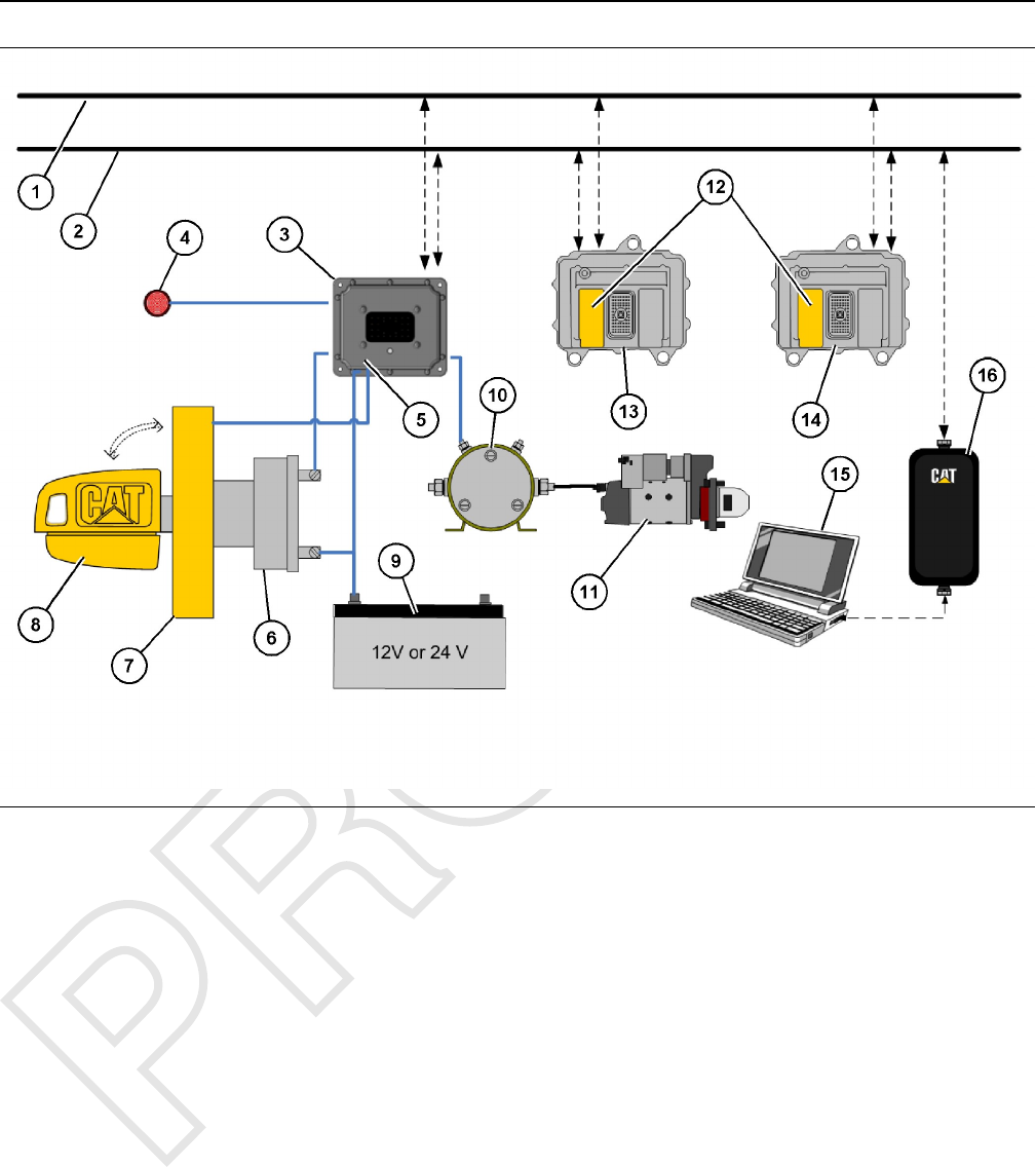
Illustration 1 g06065503
Machine security system (MSS3s)
(1) SAE J1939
(2) Caterpillar Data Link
(3) Machine Security System Standalone
ECM (MSS3s)
(4) MSS Status Indicator
(5) MSS Software
(6) Keyswitch
(7) Exciter Coil
(8) MSS Electronic Key
(9) Battery 12V or 24V
(10) Relay
(11) Starter
(12) Immobilizer Software
(13) Critical System (Transmission ECM)
(14) Critical System (Engine ECM)
(15) Communications Adapter
(16) PC Caterpillar Service Tool (ET or
PSPS)
The MSS3s ECM for the machine security system is
a hardened computer that is designed specifically for
the MSS.
The Cat ®electronic key for the MSS contains an
electronic chip that is embedded in the head of the
key. This chip in the head of the key contains a
unique identification number. The Cat ®electronic key
uses the same key cut as the standard Cat ®key. The
electronic key can be used to operate any machine
that uses the current Cat ®keyswitch. The Cat ®
electronic key comes in a gray color or a yellow color.
Cat ®electronic keys are not configurable.
The exciter coil of the MSS is a ring shaped device.
The exciter coil is mounted around the existing Cat ®
keyswitch. The exciter coil is used to read the ID that
is contained in the Cat ®electronic key.
Note: Ensure that you have only one electronic
key near the exciter coil when the MSS reads the
key. If more than one electronic key is near the
exciter coil, the MSS3s ECM will not read the key
and the machine will not start.
UENR7061 5
Systems Operation Section

The status indicator for the MSS is mounted in the
dash of the machine near the keyswitch. The status
indicator will give basic information about the MSS to
the operator of the machine. The status indicator has
two colors: red and green.
i06222272
System Overview
SMCS Code: 7631
The machine security system (MSS) is designed to
restrict operation of a machine. A list of the
authorized electronic keys for a machine is contained
in the electronic control module (ECM) for the MSS.
Only a Cat ®electronic key that is authorized can
disarm the MSS. Disarming is accomplished by
assigning the ID of an electronic key to the ECM for
the MSS. The Cat ®Electronic Technician (Cat ®ET)
service tool must be used to program the ECM with
the authorized keys.
When the exciter coil is used with MSS, the electronic
key is placed in the keyswitch of the machine and
turned to the ON position. The ECM will read the
unique ID that is stored in the key. The ECM will then
compare this ID to the list of authorized keys.
If the ID of the key that is read matches an authorized
key, the following actions will occur:
• The status indicator will turn a green color.
• The MSS will disarm allowing the machine to
operate.
If the ID of the key that is read does not match the list
in the ECM, the following actions will occur:
• The status indicator will become a red color.
• The MSS remains in the armed state.
• The machine will remain disabled.
Note: Ensure that you have only one electronic
key near the exciter coil when the MSS reads the
key. If more than one electronic key is near the
exciter coil, the MSS3s ECM will not read the key
and the machine will not start.
The machine security system can be installed in a
combination of ways:
1. Electronic Control
The MSS disables the machine by controlling up
to two devices (relays) that are used to power a
critical machine system.
2. Immobilizer
The MSS disables the machine by communicating
with other electronic control modules across the
J1939 CAN Data-Link and Cat ®Data- Link (CDL)
by disabling critical machine functions.
To change the list of authorized keys or configuration
parameters, the user must have one of the following
items:
• Cat ®Electronic Technician (Cat ®ET) service tool
and a key with master access level for that specific
machine security system
• Cat ®ET and a factory password
When a key with the master access level is not
available, a factory password is required to change
certain parameters in the configuration.
Refer to Testing and Adjusting, “Factory Password -
Obtain” for additional information on factory
passwords.
The Cat ®ET screen for the factory level security
password will display the following parameters:
• ECM serial number
• Product ID (Serial number of the machine)
• Serial number of the service tool
• Reason code
• Total tattletale number
To obtain the proper passwords, the information must
be given to an authorized Cat ®dealer.
If a key with the master access level for the machine
is not available, a factory password must be entered
before changes can be made. The following
information is needed before you call for a factory
password:
Table 1
Information That is Needed for the Factory Password
Product Identification
Software Part Number from
MSS3s ECM
Serial Number from ET
Tattletale
Reason Code 99
or
4
6 UENR7061
Systems Operation Section

Note: The password may only be used for one
programming session. A different password will
be required after you exit the Cat ®ET screen.
i06222274
Normal Operation
SMCS Code: 7631
Reading the ID of a Key
Before you can operate the machine, the MSS must
identify a valid electronic key ID. The MSS identifies
a valid electronic key ID via the exciter coil.
Exciter Coil
When the key is turned to the ON position, the MSS
enters the read mode. The MSS then checks for a
valid electronic key ID. If the electronic key ID
matches one stored in the MSS3s ECM, then power
is supplied to the output drivers of the MSS3s ECM.
An “enable”message is also sent via the CAT data
link to the other electronic control modules that are
on the machine. The machine will operate normally.
Note: Ensure that you have only one electronic
key near the exciter coil when the MSS reads the
key. If more than one electronic key is near the
exciter coil, the MSS3s ECM will not be able to
read the key. If the MSS3s ECM cannot read the
key, the machine will not start.
Note: If the MSS3s ECM has failed or been removed,
the other critical machine operations controlled by the
other electronic control modules will not operate.
Timeouts
After a machine has been started successfully, the
operator will have 30 seconds after the machine is
turned off before the MSS is automatically armed.
The operator is not required to arm the system
manually.
If the MSS is unable to read an electronic key ID, the
system will remain armed.
When the MSS identifies a key with an invalid
electronic key ID, the system will remain armed.
Armed
When the MSS is armed, the output drivers are open.
The output drivers being open, disables the power
that is supplied to each component that is powered
by the output drivers. The machine will not be able to
operate normally. When the system has been armed,
the red LED of the status indicator will illuminate.
There are two states of operation within the “armed”
mode.
1. ““MSS Armed””
When no power is applied to the MSS, the MSS
will default to “armed”state. When power is
applied to the MSS, and all timeouts have expired,
the MSS will return to the “MSS Armed”.
2. ““MSS Read””
Exciter Coil
When the keyswitch is first moved to the ON
position, the MSS tries to read the electronic key
ID. The ECM will continue reading attempts until
an ID is read or the read timeout expires. If an ID is
read, the MSS changes to the “MSS read”state. If
the read timeout expires, the MSS will turn on the
red LED of the status indicator and the MSS will
remain armed.
Note: Ensure that you have only one electronic
key near the exciter coil when the MSS reads the
key. If more than one electronic key is near the
exciter coil, the MSS3s ECM will not be able to
read the key. If the MSS3s ECM cannot read the
key, the machine will not start.
Disarm
When the MSS is disarmed, the machine can be
operated. The MSS has enabled the starter and main
circuits on the machine. A message is sent to the
other machine ECMs over the J1939 and Cat data
links. The machine will be able to start. The green
LED of the status indicator will illuminate.
There are two ways to disarm the machine:
• Use a valid electronic key for this machine.
• Use the Cat Electronic Technician with a “Master
Access Level”key or a factory password to modify
the configuration of the system.
i06222275
Operation of Status Indicator
SMCS Code: 7631
The Machine Security System uses a status indicator
that is mounted in the cab near the key start switch.
The status indicator provides a visible alert of the
presence of the security system. When the MSS is
armed and the “key start switch”is first turned to ON
or START, the status indicator momentarily displays a
red light. This light provides a warning that the
machine is armed with a security system.
UENR7061 7
Systems Operation Section
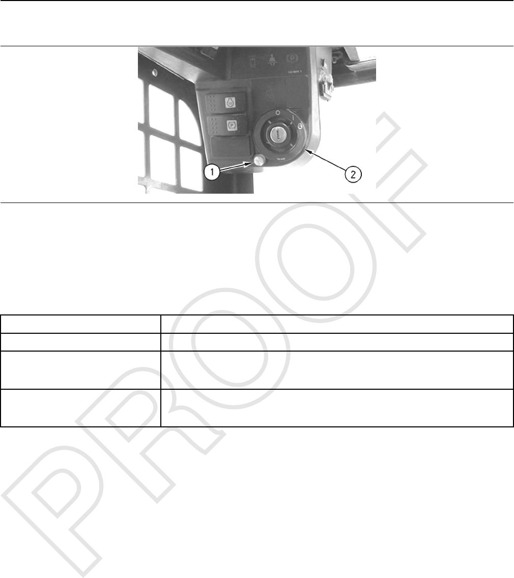
Status Indicator
Illustration 2 g01002949
Typical installation of the Status Indicator
(1) Status Indicator (2) Keyswitch with Exciter Coil
The state of the MSS is displayed by the status
indicator in accordance with Table 2 . The operator
can use the status indicator to determine the status of
the system or for troubleshooting.
Table 2
Status Indicator Description
Continuously Red The MSS is armed.(1)
Continuously Green The MSS is disarmed.
The green LED will remain ON 30 seconds after powerdown. After the 30 seconds have passed,
the MSS automatically returns to the “armed”mode.
Continuously Orange(2) The red LED and the green LED of the status indicator are tested momentarily by the
MSS3s ECM at powerup.The status indicator will remain on if No ““application”” software is
detected in the electronic control module (ECM).
(1) The red LED will remain ON while the key is in the ON position or until a valid key is read. The red LED will turn OFF approximately 3 seconds
after the key is turned to the OFF position.
(2) The red LED and the green LED are continuously ON.
i06222276
Key Information
SMCS Code: 7631
You may configure the machine security system to
recognize 255 authorized keys. This list contains
those keys that will disarm the machine security
system. The user adds keys to this list.
The ECM can store five configuration parameters
that identify each electronic key. These parameters
are listed below:
• Description
• Access level
• Expiration date
• ID1
• ID2
• Key Type
The parameters are not stored in the electronic key.
A complete list of the configuration parameters that
are available in the Cat ®Electronic Technician (Cat ®
ET) are listed below:
1. Add an electronic key.
2. Change the following information that is related to
the electronic key.
a. Access level
b. Expiration date
c. Description
3. Delete an electronic key.
4. Security bypass times
8 UENR7061
Systems Operation Section

5. Set the internal clock.
6. Fleet configuration
Note: Refer to the Testing and Adjusting, “Key -
Program” section for additional information on items
2.a, 2.b,2.c,3, 5, and 6. Refer to the Systems
Operation, “System Disarm Feature” section for
additional information on item 4.
Note: A single electronic key can be used on as
many machines with an MSS as desired. A separate
key for every machine is not necessary. Key
strategies will vary depending on machine fleet
usage. The following parameters can be different on
each machine: Description, Access Level and
Expiration Date. The ID will be the same on all the
machines.
Note: The features of the MSS are supported in
version 2015B or later of the Cat® ET service tool.
Table 3
Security Type Description Access Level Expiration Security ID
Key Operator 1 Master "_ _ _ _ _" 0:183243096
Key Operator 2 Standard "_ _ _ _ _" 0:110105956
Security Type
The security type identifies the type of security
access that is being utilized. There are currently two
types of security identification.
• Key
Security ID
The ID that is stored in the electronic key is a 16-digit
number that is displayed as two 8-digit numbers in
the Cat ET service tool. This field is known as
“Security ID”. When the numbers are combined, the
complete ID number is formed. The ECM uses this ID
to associate a key to the set of parameters in the list
of keys. Entries in the list may have the same
information for Description, Access Level, and
Expiration Date. You may choose a description of 11
characters or less for each key in the list of keys.
There can be multiple entries in the list with the same
description. Create a description so that the key
describes either the owner of the key or the function
of the user.
Note: Do not make duplicate descriptions for the
electronic keys.
Access Level
You may assign one of two access levels to a key in
the list of keys. The levels are either “Standard”or
“Master”. Both access levels allow the key to disarm
the system for operation. The master access level
also gives the user the ability to modify the settings of
the MSS with the Cat ®ET service tool.
The standard access level is for normal operation of
the machine. The master access level should be
restricted to those persons that need to modify the
settings of the machine security system.
Expiration Date
An expiration date may be assigned to any key in the
list of keys. This expiration date is defined in 6 hour
intervals on a given date. The third entry in Table 3
contains an expiration date. For all of the other keys
in Table 3 , the column with the expiration date is
filled with “Dashed lines”.“Dashed lines”indicate
that those entries do not have an expiration date. The
machine security system has an internal clock. Once
the internal clock has passed the expiration date for a
key, that key will no longer disarm the system.
However, the entry will not be deleted from the list of
keys. A new expiration date can be set, or the feature
can be disabled. A possible use for the expiration
date is used with a rental contract.
UENR7061 9
Systems Operation Section

Note: If the machine is running when the expiration
date and time are reached, the machine will continue
to run. When the machine is shut down and the 30
second grace period has timed out, the machine will
not be allowed to restart.
i06222281
Scheduled Access
(“Security System Bypass
Times”)
SMCS Code: 7631
The Machine Security System can be programmed to
disarm temporarily for a time period. The MSS can be
set to disarm for different time periods on each day.
Within these periods of time, any Caterpillar key (a
standard key or an electronic key) will operate the
machine.
Note: It is not possible to configure the ““bypass
times”” for an individual electronic key. The
““bypass times”” are not associated to an
individual electronic key.
“Security System Bypass Times”are time periods
that can be set to disarm the Machine Security
System automatically. An electronic key is not
required during these periods. This feature can be
used for the normal work shift of the machine.
Outside the normal work shift, the Machine Security
System would be armed. When the MSS is armed,
an electronic key is required to start the machine.
This feature would minimize the number of electronic
keys that are needed.
Table 4
“Sunday Security System Bypass Start Time”00:00
“Sunday Security System Bypass Stop Time”00:00
“Monday Security System Bypass Start Time”6:00
“Monday Security System Bypass Stop Time”18:00
“Tuesday Security System Bypass Start Time”6:00
“Tuesday Security System Bypass Stop Time”18:00
“Wednesday Security System Bypass Start Time”6:00
“Wednesday Security System Bypass Stop Time”18:00
“Thursday Security System Bypass Start Time”6:00
“Thursday Security System Bypass Stop Time”18:00
“Friday Security System Bypass Start Time”6:00
“Friday Security System Bypass Stop Time”12:00
“Saturday Security System Bypass Start Time”12:00
“Saturday Security System Bypass Stop Time”12:00
Table 4 shows an example of “Security System
Bypass”. The “Start Time”is the time when the
Machine Security System will disarm. The Machine
Security System will return to the “armed”state at the
“Stop Time”. Between these two periods of time, any
Caterpillar key will operate the machine. Thus, the
MSS is disarmed during this time period.
All times are based on a 24 hour clock. For example,
6:00 am is 06:00 and 3:00 pm is 15:00. The Machine
Security System will be disarmed during the times
that are listed below: Monday through Thursday from
06:00 to 18:00
On Friday, the MSS is disarmed for only half of the
workday. After 12:00 on Friday, the Machine Security
System will be armed automatically. Operation will be
restricted to operators with electronic keys that are
authorized in the MSS3s ECM on that machine.
Refer to Table 4 .
The Machine Security System is “armed”on the
weekend. Because the “Start Time”and the “Stop
Time”are set for the same time, the Machine
Security System will be armed throughout the day.
i06222289
Diagnostic Operation
SMCS Code: 7631
A diagnostic code indicates that the ECM has
detected one or more of the following conditions:
• an invalid signal from an input
• an improper feedback from an output
• an internal error
One method of displaying diagnostic information is
provided:
• Diagnostic codes with descriptive text can be
viewed with the Caterpillar Electronic Technician
(ET).
Display the diagnostic code with the Caterpillar
Electronic Technician.
This method of displaying the diagnostic codes uses
the service tool to display the codes. The Component
Identifier (CID) identifies the specific component for a
specific diagnostic. The Failure Mode Identifier (FMI)
identifies the type of diagnostic that was detected.
The diagnostic codes allow consistent identification
of the problem. The service tool is used to display the
CID-FMI with descriptive text for each combination.
The descriptive text will help to avoid mistakes in
interpreting the codes.
10 UENR7061
Systems Operation Section

Active Diagnostics
Active diagnostics indicate the presence of active
diagnostic codes in the MSS. A diagnostic code
informs the operator that a problem exists with the
MSS.
If the Cat service tool is available, the service tool
can be used to display all active diagnostic codes.
The service tool will also display codes that have
been logged.
Logged Diagnostics
A logged diagnostic will record problems that are
intermittent in the Machine Security System. Logged
diagnostics eliminate the need to duplicate problems
that are intermittent. Logged diagnostics will increase
the accuracy of diagnosis. The time that is required to
troubleshoot a problem is reduced with the use of
Diagnostics. Logged diagnostics eliminate the need
for trip recorders that are used to capture intermittent
diagnostic information.
The memory of the control module is used to store
diagnostic information. When a diagnostic code is
detected, the following information is logged:
• The CID will identify the component that has
failed.
• The FMI will describe the problem.
• Number of occurrences of the diagnostic code
• The time of the first occurrence that the diagnostic
was detected.
• Last occurrence time, when the diagnostic was
last detected (stored with both machine hours and
RTC stamp)
The problems which can be logged are listed in
Troubleshooting, “Diagnostic Code Procedures”.
The MSS logs the number of times that the machine
is started with the methods that are listed below:
• Starting using an unauthorized method
i06222291
Events
SMCS Code: 7631
An event indicates that the MSS is not operating
correctly. An event does not indicate that there is a
failure with the system.
The MSS records data for the events that are listed in
Table 5 .
Cat ®Electronic Technician (Cat
ET)
When an abnormal operating condition occurs, the
status screen on Cat Electronic Technician (Cat ET)
indicates that there is an active event.
Event codes are displayed on Cat ET in the following
format:
EXXXX Description of the code
The “E”means that the code is an event code. The
“XXXX”is a numeric identifier. The numeric identifier
is followed by a description of the code.
Active event codes are listed in ascending numerical
order. The code with the lowest number is listed first.
The active event code is removed from the list when
the condition is no longer present.
Logged Event Codes
Some event codes are logged in the ECM memory.
Some event codes are active only. The logged event
codes are listed in chronological order. The most
recent code is listed first.
A logged code is cleared from memory when one of
the following conditions occur:
• The service technician manually clears the code.
• The code does not reoccur for 1000 hours.
• A new code is logged and there are already ten
logged codes in memory. In this case, the oldest
logged code is cleared.
Note: Always clear logged event codes after
investigating and correcting the problem which
generated the code.
UENR7061 11
Systems Operation Section

Table 5
Events that are logged by the Machine Security System
EID Description Possible Cause/Recommended Response
E273 “Machine operation attempted using an inva-
lid key”
Probable Cause: An unrecognized key has been used to start the
machine.
Recommended Action: Ensure that key list is up to date with all required
keys.
E252 “Loss of Key Table Information”
Probable Cause: Possible loss of key table.
Recommended Action: Check key table to ensure that it is correct. Possi-
bly caused by improper machine shutdown.
12 UENR7061
Systems Operation Section
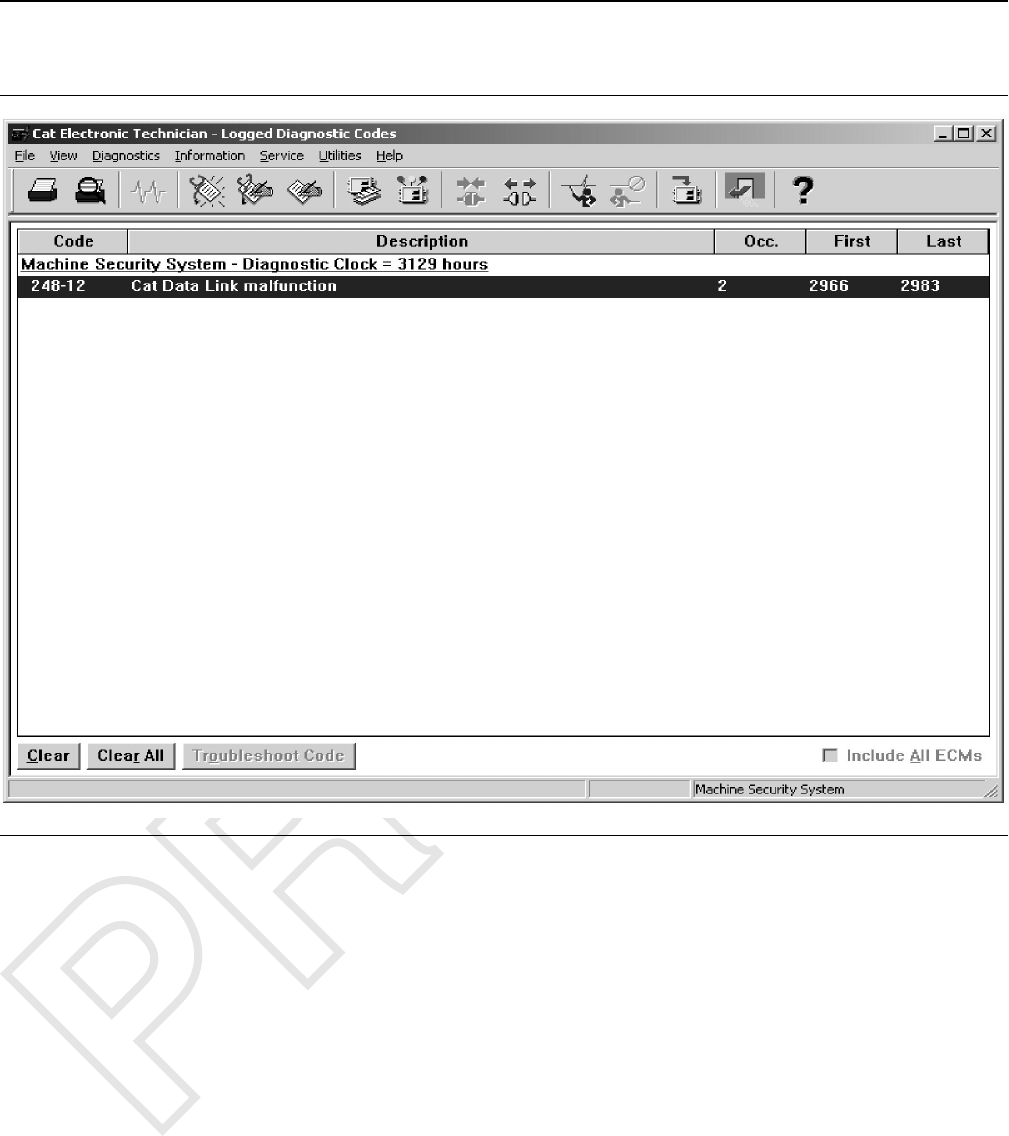
Logged Events
Illustration 3 g01097063
“Logged Event Codes”screen from theCaterpillar ®Electronic Technician for the Machine Security System
Logged events provide a secure list of events that are
critical to the security of the machine. The ECM for
the MSS is used to store information about events.
When an event is detected, the following information
is logged:
• EID for the event
• Number of occurrences
• Time of the first occurrence of the event
• Time of the last occurrence of the event
Note: The ECM will record a maximum of 127
occurrences of the events. The newest event
replaces the oldest event after 127 events have been
stored in the memory of the ECM.
i06222294
Protected Functions
SMCS Code: 7631
There are two levels of protection:
• An electronic key with standard access level and a
non-electronic key
• An electronic key with master access level (factory
password)
The requirements for each level are explained below:
UENR7061 13
Systems Operation Section

An Electronic Key with Standard Access Level
and a Non-electronic Key
• The table of the MSS keys can be viewed but the
table cannot be modified.
• The configuration settings of the MSS can be
viewed but the settings cannot be modified.
Electronic Key with Master Access Level
A factory password or a master access level is
needed to modify any settings through the service
tool.
• The settings for the MSS can be modified.
• The list of valid key IDs can be modified.
• The logged events can be cleared.
i06222298
Service Operation Using
Machine Security System
SMCS Code: 7631
The onboard interface has several purposes. The
interface can provide the following information to the
operator: diagnostic feedback and event feedback.
The system can also be programmed through the
onboard interface.
i06222303
Service Operation Using
Service Tool
SMCS Code: 0785-UE; 7631
The service tool is used to communicate with the
ECM for the following information:
• display and control of code
• programming
• management
• diagnostics
• events
To protect the machine properly, the service tool
requires a factory password or a key with the master
access level. This password or key is required before
any modifications can be made to the MSS.
i06222310
Electronic Control Module
(ECM)
SMCS Code: 7610-MCH
FCC NOTICE
This device complies with Part 15 of the FCC Rules.
Operation is subject to the following two conditions:
1. This device may not cause harmful interference.
2. This device must accept any interference received,
including interference that may cause undesired
operation.
Industry Canada Notice to Users
This device complies with Industry Canada licence-
exempt RSS standard(s). Operation is subject to the
following two conditions:
1. This device may not cause interference.
2. This device must accept any interference,
including interference that may cause undesired
operation of the device.
14 UENR7061
Systems Operation Section
Le présent appareil est conforme aux CNR
d'Industrie Canada applicables aux appareils
radio exempts de licence. L'exploitation est
autorisée aux deux conditions suivantes :
(1) l'appareil ne doit pas produire de brouillage,
et
(2) l'utilisateur de l'appareil doit accepter tout
brouillage radioélectrique subi, même si le
brouillage est susceptible d'en compromettre le
fonctionnemen
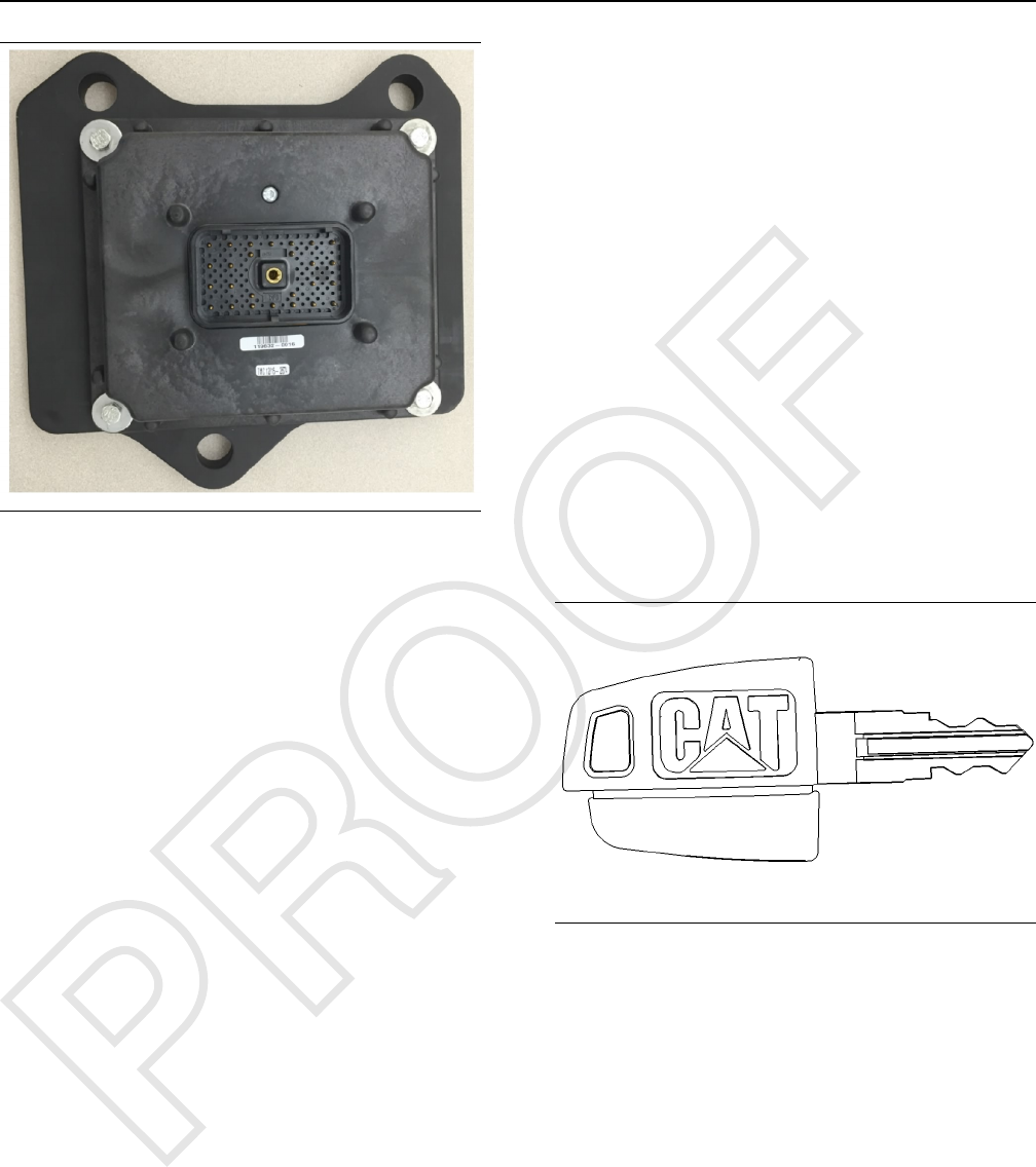
Illustration 4 g06105748
ECM Inputs
Keyswitch
The key start switch is also used as an input signal to
the MSS. The input from the key switch is used to
determine when the machine is on. Battery voltage is
connected to this input through the ON and START
positions of the keyswitch. When the machine is
operating and the alternator is charging, the voltage
on this input will be:
• 14.1 - 15.1V for a 12V system
• 27.6 - 29.6V for a 24V system
When the machine is not running, the voltage on this
input will be approximately 12V for a 12V system and
24V for a 24V system.
Neutral Start Input
When activated, the NEUTRAL START input supplies
power to the neutral start ON/OFF driver 5
(STARTER solenoid driver) using +BATT.
Switch to ground
These inputs allow the ECM to detect closure of
switches to the ECM ground (- BATTERY input).
ECM Outputs
Status Indicator
The status indicator displays status of the system.
The status indicator has three connections. One of
the three connections is for a ground. Another
connection is for the red LED. The third connection is
for the green LED.
Output Drivers
Two output drivers are available to control relays or
solenoids on the machine. Unless a valid “key ID”
has been identified by the system, the drivers will
remain without power. The drivers are rated at 2A.
i06222315
System Components
SMCS Code: 7631
Cat® Electronic Key
Illustration 5 g00793955
The Cat® electronic key
The Cat® key is the universal key for all Caterpillar
machines. The electronic key has an electronic chip
that is embedded inside the head of the key. The
electronic keys are gray or yellow.
Exciter Coil
The exciter coil provides communication between the
electronic key and the control module.
The exciter coil is mounted around the keyswitch.
This position allows the exciter coil to communicate
with the electronic key. Any ferrous metal between
the coil and the electronic key will interfere with the
communications. Mounting the coil in the same plane
as the top of the keyswitch will minimize the
interference.
UENR7061 15
Systems Operation Section
Note: Ensure that you have only one electronic
key near the exciter coil when the machine
security system (MSS) reads the key. If more than
one electronic key near the exciter coil, the
MSS3s ECM will not read the key and the
machine will not start.
The exciter coil is connected to the harness via a 2-
pin connector and a length of wire.
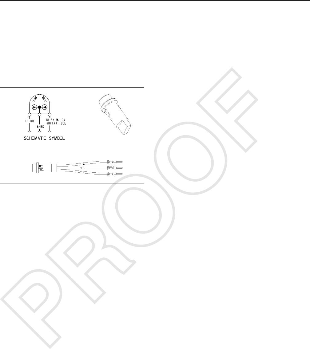
Status Indicator
Illustration 6 g00862013
The state of the MSS is displayed by the status
indicator. The green LED of the status indicator turns
on when the system is disarmed. The machine
should start. The red LED of the status indicator turns
on when the system is armed and an invalid
electronic key has been read by the MSS. The
machine should not start. Both LEDs will turn on,
producing an orange light if the application software
of the MSS has not been programmed into the ECM.
i06752745
Data Links
SMCS Code: 7631
The J1939 and Cat Data Link can connect the ECM
for the MSS to the following items:
• Service tools
• Onboard controls
• Monitoring systems
The service tool can send information to the MSS
through the J1939 and Cat Data Link. The MSS can
provide information over the J1939 and Cat Data Link
to transmission control, engine control, and service
tool. The information can be for diagnostics, or the
information can be used to control other systems on
the machine.
16 UENR7061
Systems Operation Section
Troubleshooting Section
Introduction
i06222327
General Information
SMCS Code: 7000
Failure of an electrical component can cause the
failure of other components. Also, failure of an
electrical component can be caused by the failure of
other components. Always attempt to correct the
cause of an electrical system failure before you
replace a component.
Note: If you suspect that there is a problem with
the Machine Security System, ensure that the
machine starting system is working properly. Use
the electrical system schematic to troubleshoot
the starting circuit.
Note: Electronic control modules seldom fail.
Perform the troubleshooting procedures that are
provided in the Troubleshooting, “Symptom
Procedures” section of this manual, before you
replace an ECM.
Test procedures progress from the most likely points
of failure to the least likely points of failure. The
procedures normally proceed in the following order:
• A component is bad.
• Wiring or connectors are bad.
• An electronic module is bad.
Each procedure assumes the following data:
• No previous troubleshooting has been performed
on the system.
• The system has not been altered.
Assume for repair:
• The batteries are fully charged and the charging
system is operating properly.
• Caterpillar ®Electronic Technician (Cat ®ET) is
available and the technician is trained on the
operation of Cat ET. See Troubleshooting,
“Service Tools”.
During troubleshooting, inspect all connections
before any component is replaced. If the connections
are not clean and tight, permanent electrical
problems or intermittent electrical problems can
result. Check that the wires are pushed into the
connectors completely. Make sure that the
connections are tight before other tests are made.
i06222332
Service Tools
SMCS Code: 0785
Standard Caterpillar ®tools should be adequate for
service. The following tools are needed to
troubleshoot the Machine Security System:
Table 6
Service Tools
Part Number Description
9U-7246 Connector Repair Kit
7X-1710 Multimeter Probe
8T-5318 Wire Removal Tool
6V-7070 Digital Multimeter
4C-4911 Battery Load Tester
In addition to the tools listed in Table 6 , a laptop
computer with the Cat ®Electronic Technician (Cat
ET) and the communication adapter are required.
The Cat ET 2015B or later is required to use the full
security management potential of the Machine
Security System.
i06229345
Connector Locations
SMCS Code: 7553-546-WW
The locations of the components of the MSS will vary
between machines. If the MSS was installed by a
Caterpillar dealer, consult the installation instructions
for component locations. If the MSS was an
attachment that was installed at the factory, consult
the electrical schematic for that machine.
For each output use a twisted wire pair, all the way
between the MSS3s ECM and the load
(recommended).
Note: There is a need to manage shared returns,
connecting the returns together as close to the ECM
as possible. Failure to do so may result in difficulty
reading keys due to electromagnetic interference.
• The 2A drivers share a separate return.
• The 300mA drivers share a separate return.
UENR7061 17
Introduction

• The 20mA LED drivers share a separate return.
• The exciter coil has a dedicated return that is not
to be shared.
Use the Machine Electrical Schematic, Parts Manual,
and Operation and Maintenance Manual to locate
electrical components and connectors.
The following information is a guide to reading the
tables on the back of the Electrical Schematic.
• The “Component Location”table uses a numeric
value for each component on the machine. Cross
reference the machine location number from the
table to the corresponding number in the machine
views graphic.
• The “Harness Connector Location”table uses a
numeric value for each connector on the machine.
Cross reference the connector number from the
table to the corresponding number in the machine
views graphic.
i06245459
Diagnostic Capabilities
SMCS Code: 1400
Diagnostic information for the Machine ECM can be
accessed using the Cat ®Electronic Technician (Cat
ET) Service Tool. Diagnostic information can also be
accessed by using the Operator Monitor Display.
18 UENR7061
Introduction
The Cat®Electronic Technician (Cat
ET) Service Tool
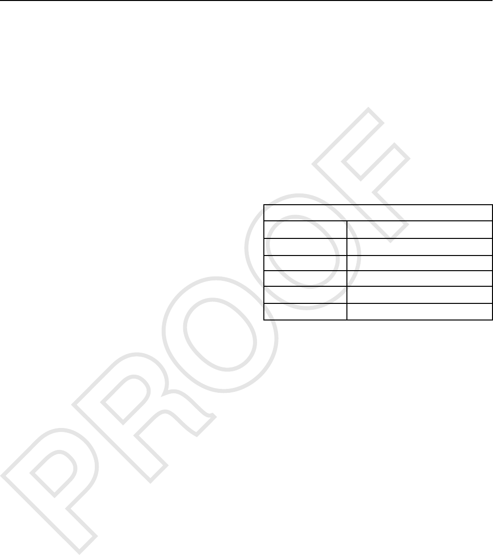
Illustration 7 g03861135
Connections for the Communication Adapter 3 and Cat ®Electronic Technician (Cat ET) Service Tool
The components that are needed to use the Communication Adapter III and Cat ET to determine diagnostic codes
are listed:
(1) Cable
(2) 317-7484 Communication Adapter Gp
(3) 457-6114 CA3 Ethernet FLASH Cable
(4) Current version of Cat ET program
software and an IBM-COMPATIBLE
personal computer
Cat ®Electronic Technician (Cat ET) is a software
program used to access, view, monitor and
sometimes change data that a particular ECM uses
to control a machine system. The service technician
can use the Cat ET to perform maintenance on the
machine. Some of the options that are available with
the Cat ET are listed below:
• View the active diagnostic codes and logged
diagnostic codes. See Troubleshooting, “Using the
Cat®Electronic Technician (Cat ET) Service Tool
to Determine Diagnostic Codes”.
• Viewing the active event codes and logged event
codes.
• View the status of parameters.
• Clear active diagnostic codes and clear logged
diagnostic codes.
• Perform calibrations of machine systems.
• Program the ECM (Flash) with the “WINflash”
program. See Troubleshooting, “Electronic Control
Module (ECM) - Flash Program”.
• Print reports.
The following list contains some of the diagnostic
functions and programming functions that are
performed by the Cat ET service tool.
UENR7061 19
Introduction
• The failures of the ECM system are displayed.
• The status of most of the inputs and the outputs
are displayed.
• The settings for the ECM are displayed.
• Display the status of the input and output
parameters in real time.
• Display the clock hour of the internal diagnostic
clock.
• The number of occurrences and the clock hour of
the first occurrence and the last occurrence is
displayed for each logged diagnostic code.
• The definition for each logged diagnostic code and
each event is displayed.
• Load new FLASH software.
• Active diagnostic codes.
• Logged diagnostic codes.
See Troubleshooting, “Diagnostic Code List” for the
list of diagnostic codes that can be activated by the
Machine ECM.
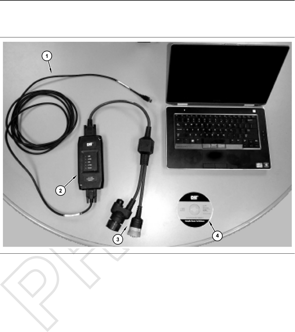
Event Codes
Logged Event Codes
Illustration 8 g02291520
Typical Cat ET screen for logged events
20 UENR7061
Introduction
An indicator for logged events is provided. The
indicator allows the service technician to track event
codes that are intermittent. The data for the logged
event will include the following information:
• An event identifier (EID).
• A text description of the problem.
• The number of occurrences of the problem.
• A time stamp will display the first occurrence of the
problem.
• A time stamp will display the last occurrence of the
problem.
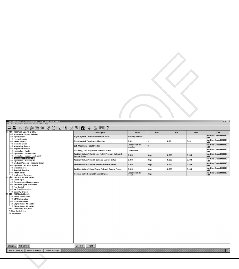
Status Groups For Cat ET
The Status groups list the machine parameters. The
status of the parameters is shown in real time.
Illustration 9 g02734437
Typical Cat ET Status Screen
UENR7061 21
Introduction
i06229353
Machine Preparation for
Troubleshooting
SMCS Code: 7000-035
Warnings
Sudden movement of the machine or release of
oil under pressure can cause injury to persons
on or near the machine.
To prevent possible injury, perform the procedure
that follows before testing and adjusting the
power train.
Hot hydraulic oil under high pressure can remain
in the components of the hydraulic system or the
power train system after the engine has been
stopped. The uncontrolled release of the hydraul-
ic oil can cause sudden machine movement and
can also result in the following conditions:
• Burns
• The penetration of body tissue
• Other personal injury
• Death
If hydraulic oil penetrates body tissue, the injury
must be treated immediately by a doctor who is
familiar with this type of injury. Use a board or a
piece of cardboard to check for a hydraulic oil
leak. Make sure that all of the attachments have
been lowered to the ground and that all trapped
pressure has been released from the hydraulic
system and the power train system. Also, make
sure that the hydraulic oil is cool before the re-
moval of any components or lines. Remove the
hydraulic oil filler cap only when the engine is
stopped and the filler cap is cool enough to touch
with your bare hand.
Personal injury or death can result from not en-
gaging the parking brake.
Transmission engagement alone will not prevent
machine from rolling when the engine is stopped.
Personal injury can result if the machine moves
while testing.
If the machine begins to move during test, reduce
the engine speed immediately and engage the
parking brake.
NOTICE
Care must be taken to ensure that fluids are con-
tained during performance of inspection, mainte-
nance, testing, adjusting, and repair of the product.
Be prepared to collect the fluid with suitable contain-
ers before opening any compartment or disassem-
bling any component containing fluids.
Refer to Special Publication, NENG2500, “Dealer
Service Tool Catalog” for tools and supplies suitable
to collect and contain fluids on Cat ®products.
Dispose of all fluids according to local regulations
and mandates.
General Procedure
1. Know the Machine
Understand the operation and the interaction of
the machine systems. Know if the symptom is a
characteristic of normal operation or if the
symptom is a problem.
Refer to the Systems Operation in your Service
Manual.
2. Identify the Symptom
a. Speak with the operator about the symptom.
• Ask about the performance of the machine
prior to the problem.
• Determine the time that the symptom first
occurred.
• Determine the operating conditions at the
time of the problem.
• Ask the operator about the sequence of
events prior to the failure. Determine the
order of the occurrences.
• Ask the operator about the steps that have
been taken to troubleshoot the machine.
• Check the history of repairs of the machine.
• Ask about the preventive maintenance of
the machine.
22 UENR7061
Introduction

b. Inspect the machine. Look for problems. Notice
any unusual odors in the air. Listen for unusual
noises.
Complete the steps in Troubleshooting,
“Visual Inspection”.
If you complete the visual inspection and the
problem is not identified, perform the
appropriate tests and/or adjustments in
Specifications, Systems Operation/Testing
and Adjusting for your machine.
3. Troubleshoot the faults with the service codes
Determine if the ECM has detected any faults. A
service code is used to specify each detected
fault.
Each of the components such as switches and
sensors are referenced by a unique CID
(component identifier).
In order to read a diagnostic code, refer to
Troubleshooting, “Diagnostic Capabilities” in this
manual.
4. Troubleshoot using the description of the
symptom
If you troubleshoot the service codes and the
problem is not resolved, continue troubleshooting
using the symptom. Identify the component that is
the most probable cause of the symptom.
5. After the problem is resolved, prepare the machine
for operation. Complete a maintenance record for
the machine: problem, symptom, and repairs.
Refer to the instructions in the Operation and
Maintenance Manual for your machine.
i06249215
Visual Inspection
SMCS Code: 7000-035
Check the Electrical System
1. Inspect the wires and check the electrical
connectors to the component that is suspect.
Expected Results
• The wires and the electrical connectors are not
damaged. The electrical connectors are clean.
Results
• OKAY: Proceed with Diagnostic Trouble Codes.
• NOT OKAY: Replace any damaged wires.
Replace any damaged electrical connectors.
Ensure that all the seals are properly in place.
Check the machine for the original problem.
UENR7061 23
Introduction