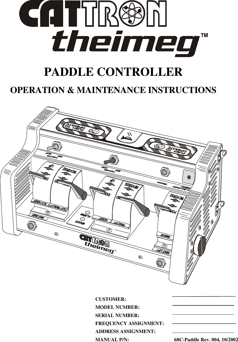
Cattron North America EPH-15 Industrial Remote Controller User Manual 004
Laird Controls North America Inc. Industrial Remote Controller 004
UserManual.wiki
>
Cattron North America
>
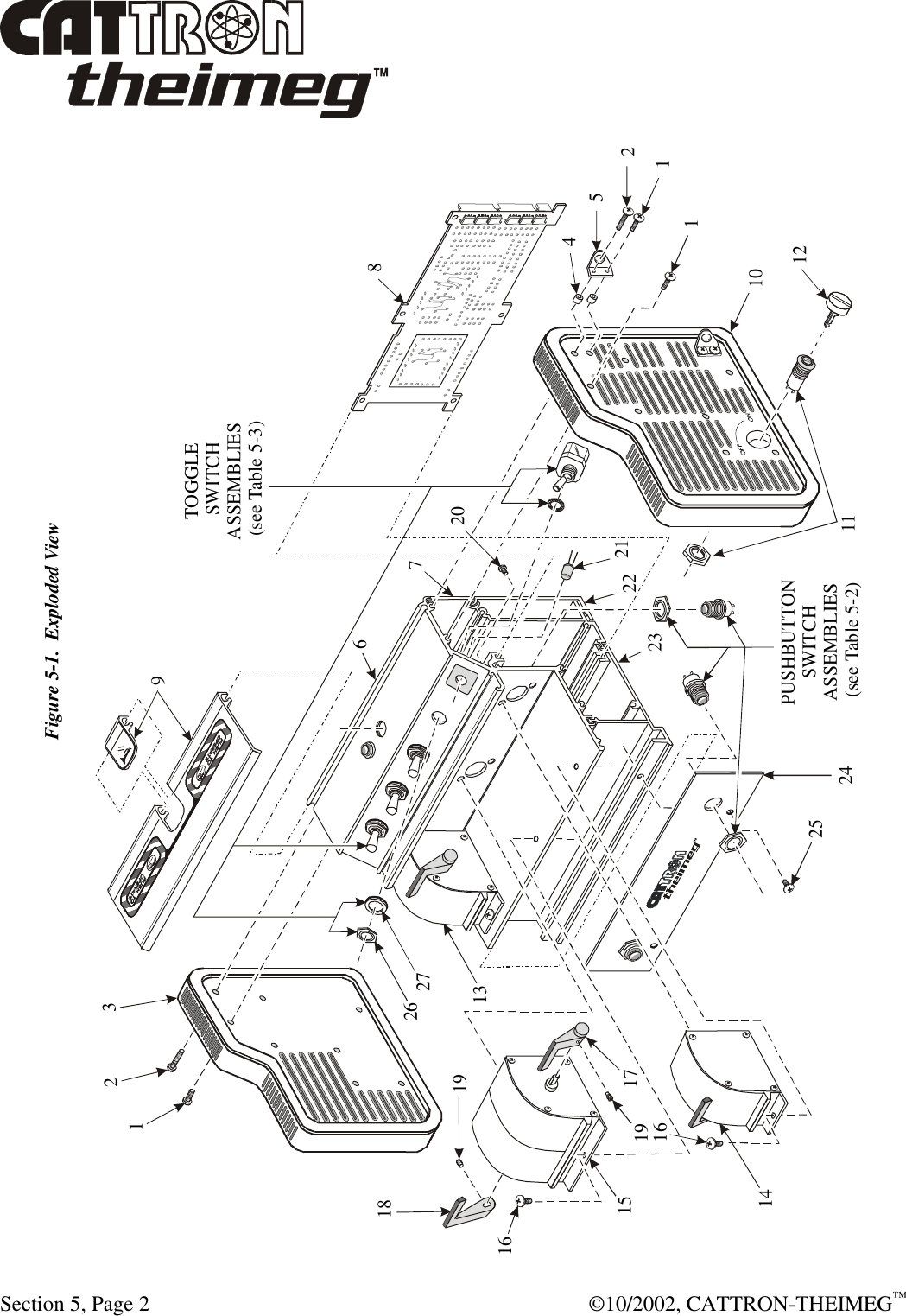
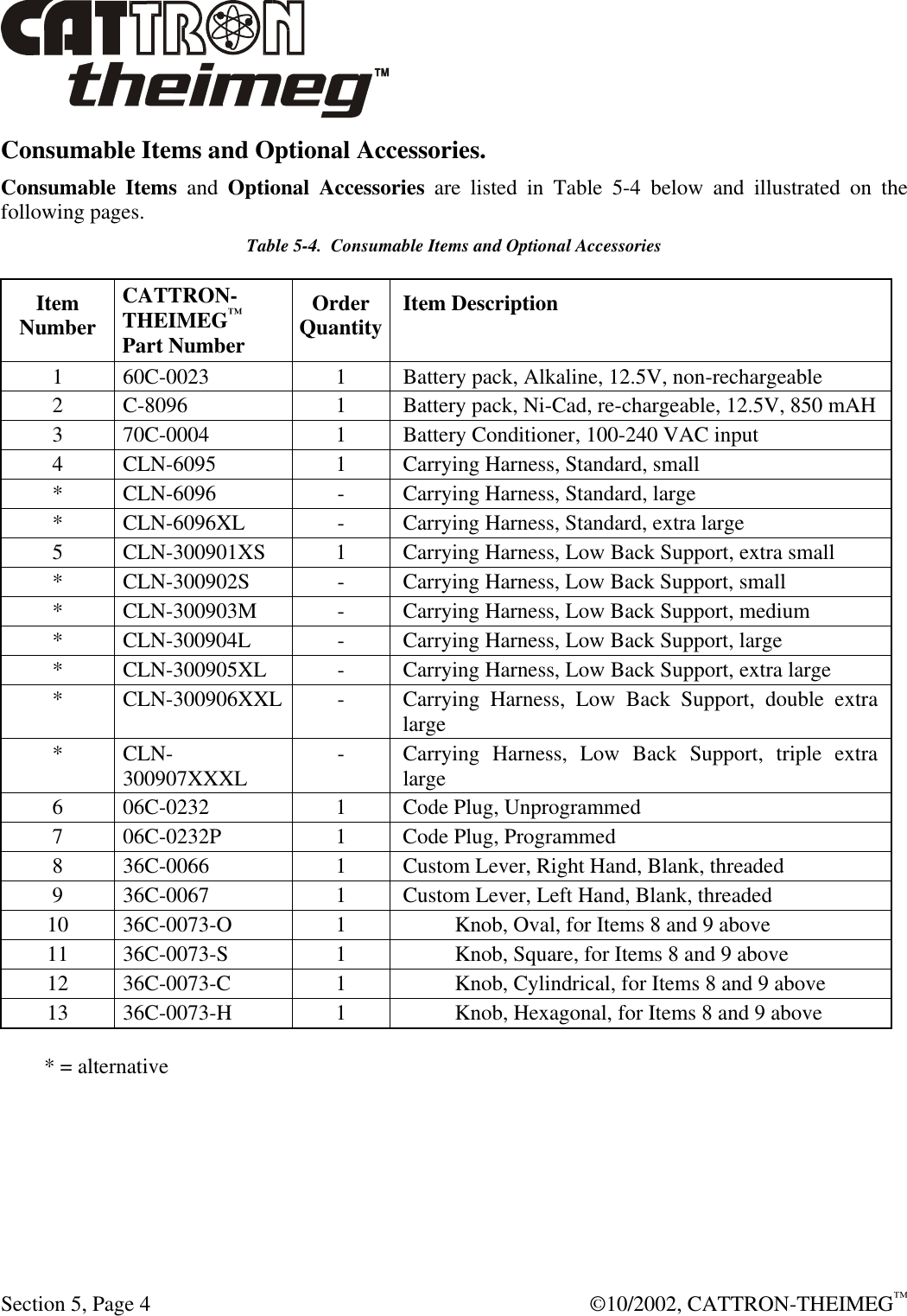
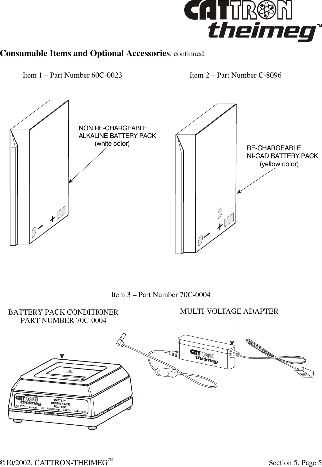
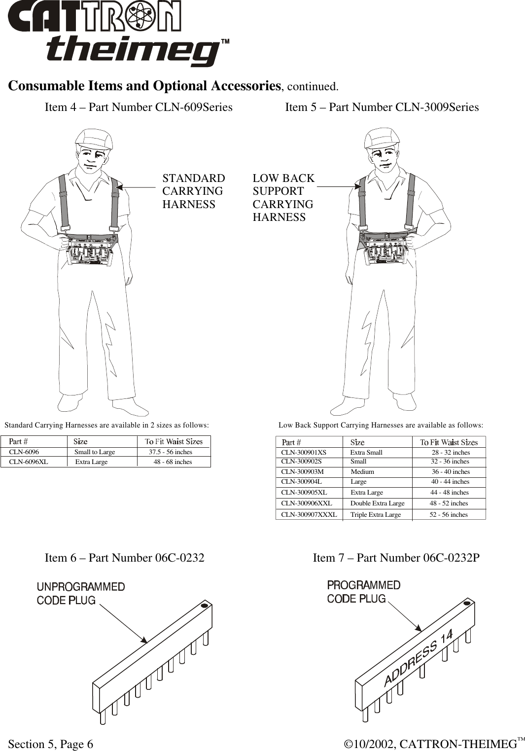
EPH 15 User Manual
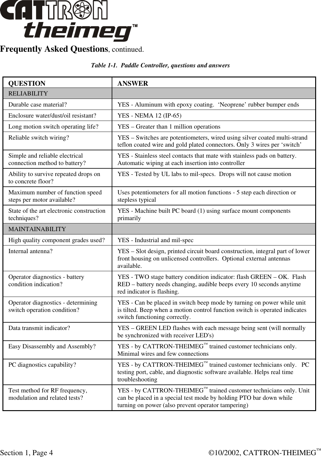
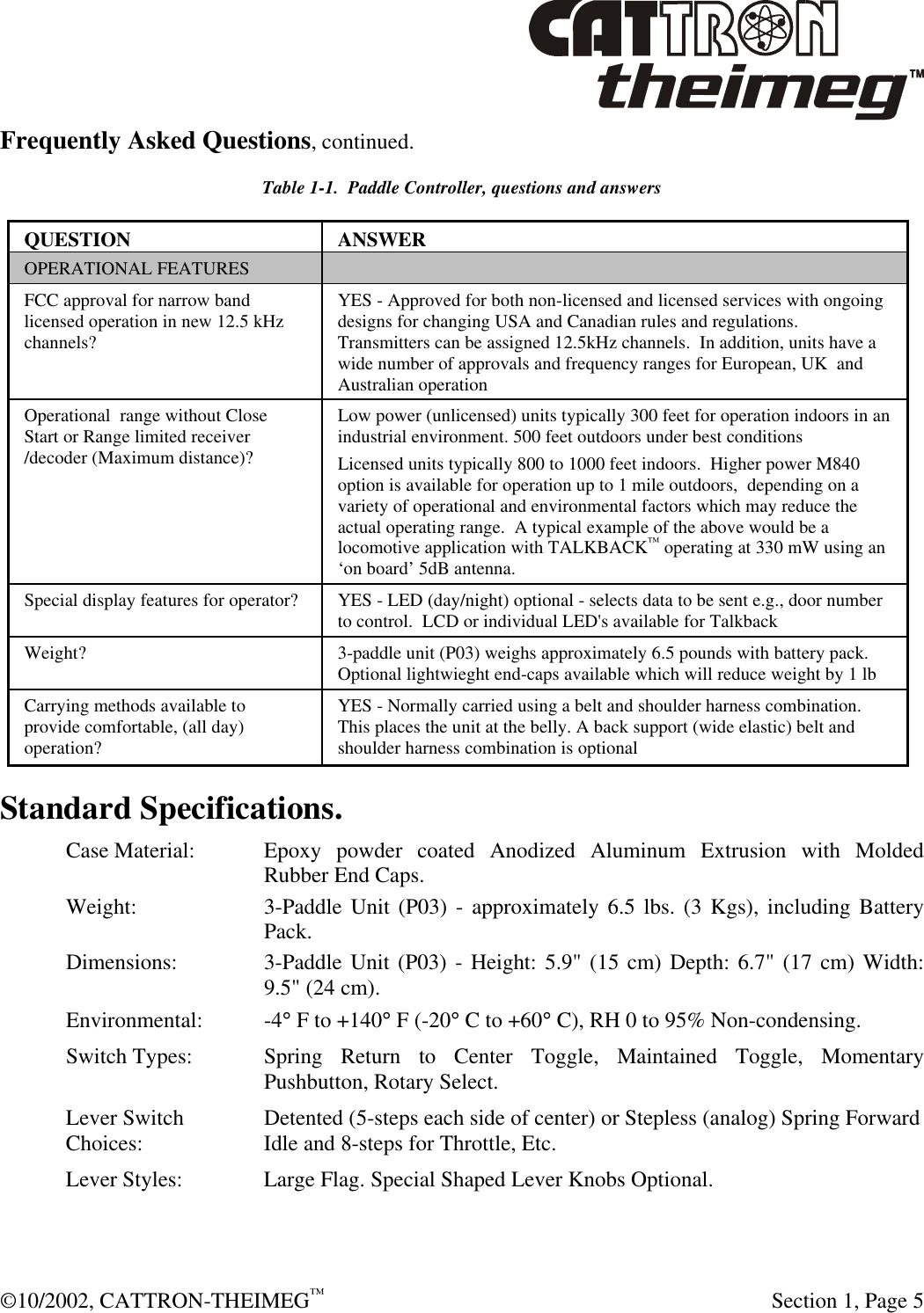
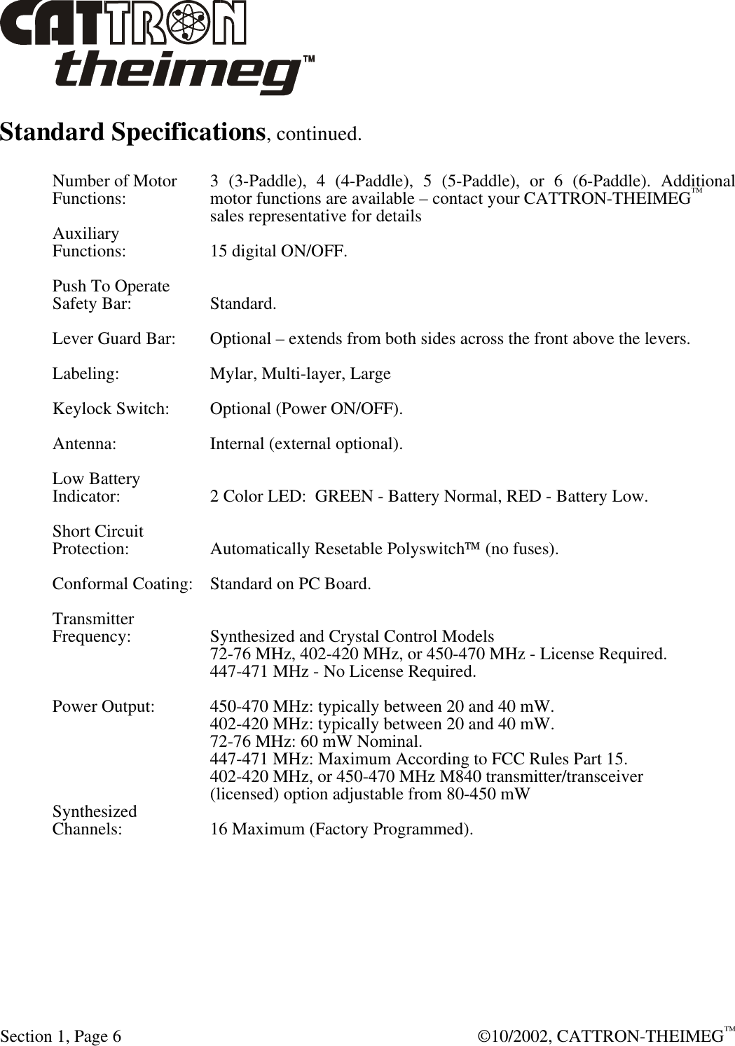
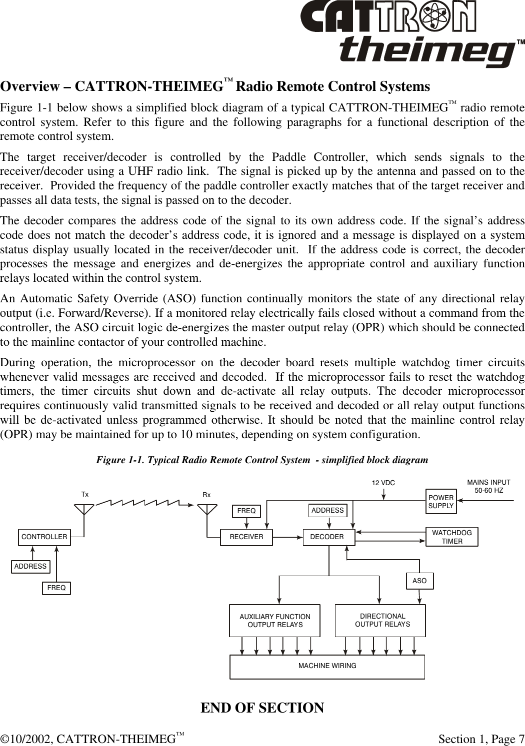
Users Manual
Navigation menu
Upload a User Manual
Namespaces
Wiki Guide
HTML
PDF
Info
Views
User Manual
Discussion / Help
Navigation