Cattron North America EXC9158A Remote Control Transmitter User Manual ct24 Excalibur User Manual eng
Laird Controls North America Inc. Remote Control Transmitter ct24 Excalibur User Manual eng
UserManual.wiki
>
Cattron North America
>
EXC9158A User Manual
Manual
Navigation menu
Upload a User Manual
Namespaces
Wiki Guide
HTML
PDF
Info
Views
User Manual
Discussion / Help
Navigation


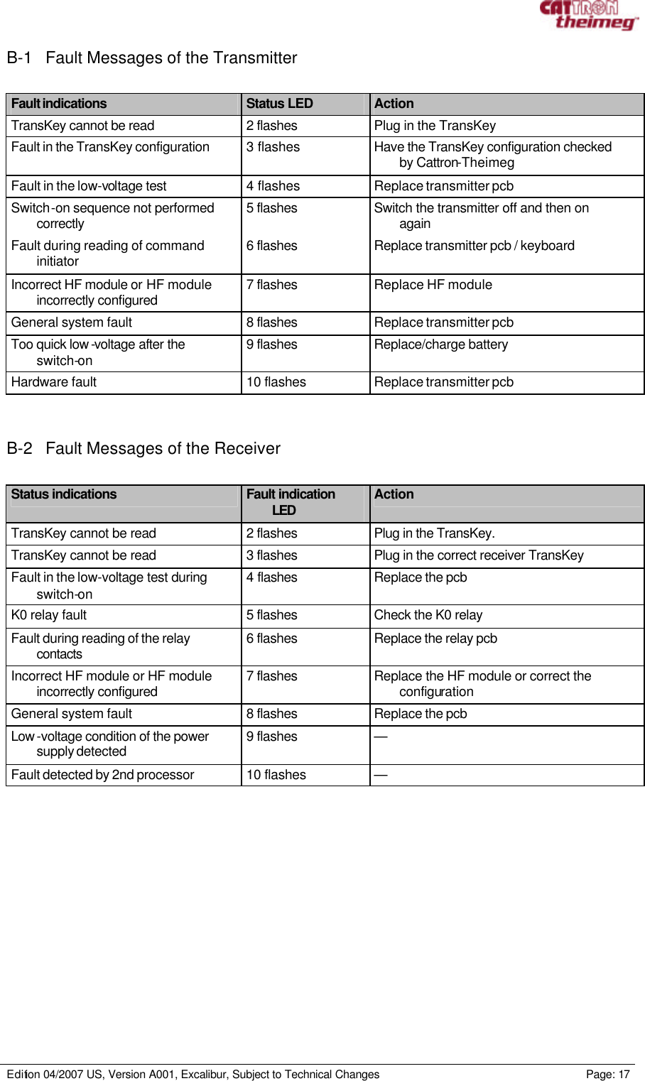
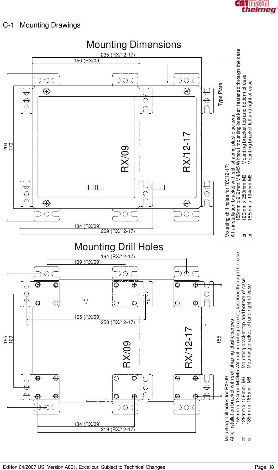
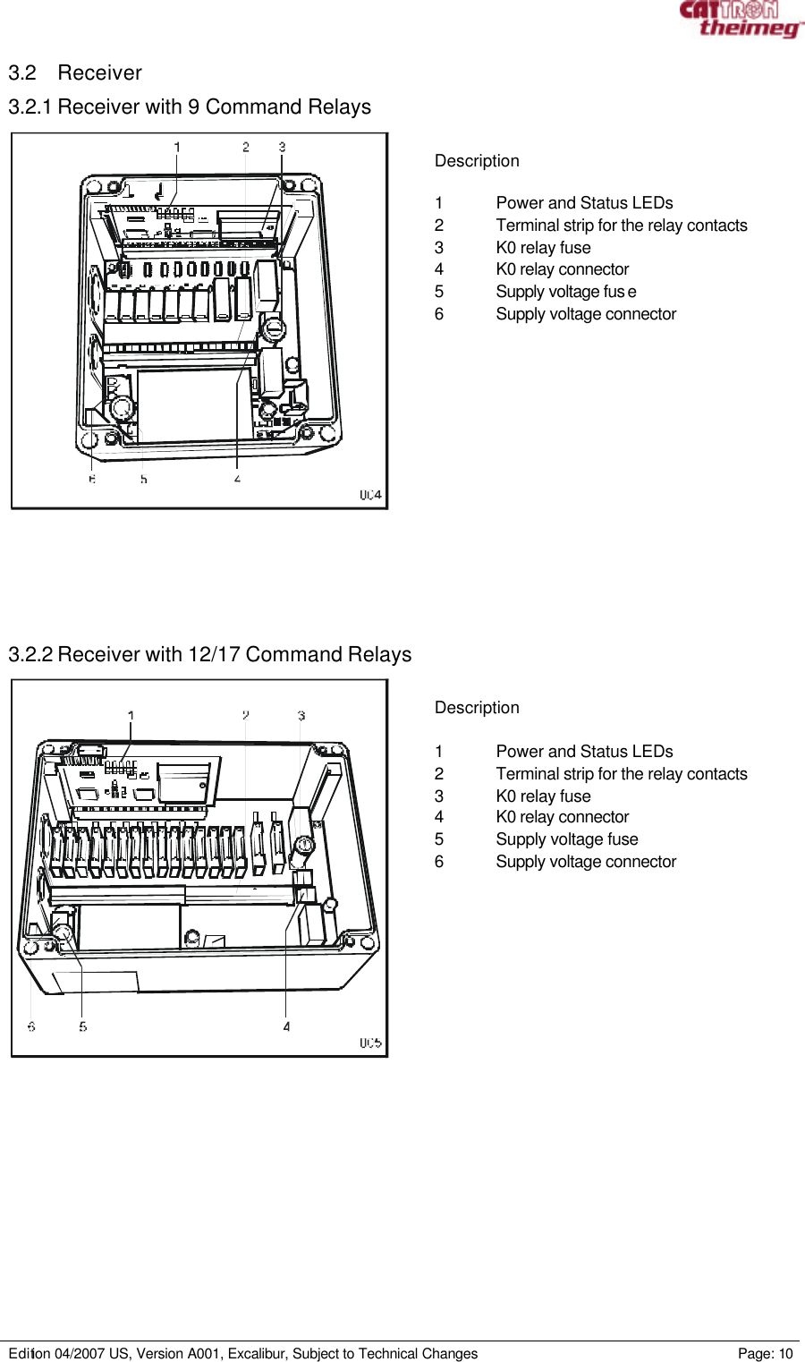
![Edition 04/2007 US, Version A001, Excalibur, Subject to Technical Changes Page: 1 Table of Contents 1. Safety Instructions....................................................................................................................................................3 1.1 General Information on Safety...................................................................................................................................3 1.2 Operation of Radio Remote Control System Components with Identical System Address..................4 1.3 Use for Intended Purpose............................................................................................................................................4 1.4 Improper Use...................................................................................................................................................................4 1.5 Safety Instructions for Assembly/Disassembly....................................................................................................4 2. Installation and Preparation.................................................................................................................................5 2.1 Battery Charger...............................................................................................................................................................5 2.2 Receiver.............................................................................................................................................................................6 2.2.1 Selection of the Place of Installation..................................................................................................................6 2.2.2 Inserting the TransKey in the Receiver............................................................................................................6 2.2.3 Installing the Receiver ............................................................................................................................................7 2.2.4 Electrical Connection of the Receiver...............................................................................................................7 2.3 Transmitter........................................................................................................................................................................7 2.3.1 Inserting the Rechargeable Battery into the Transmitter:...........................................................................7 2.3.2. Transmitter Labelling..............................................................................................................................................7 3. Putting into Operation.............................................................................................................................................8 3.1 Transmitter........................................................................................................................................................................8 3.1.1 Transmitter Variants ................................................................................................................................................8 3.1.2 Switching On the Transmitter:.............................................................................................................................8 3.1.3 Transmitter Blink Sequences [Status Indications] of the Status-LED....................................................9 3.1.4 Switching Off the Transmitter:.............................................................................................................................9 3.1.5 TransKey.....................................................................................................................................................................9 3.2 Receiver...........................................................................................................................................................................10 3.2.1 Receiver with 9 Command Relays ...................................................................................................................10 3.2.2 Receiver with 12/17 Command Relays ..........................................................................................................10 3.2.3 Relay Status Indication.........................................................................................................................................11 3.2.4 Power und Status Indication...............................................................................................................................11 4. Charging the Transmitter Batteries with the Battery Charger ...........................................................12 4.1 Functional Overview ....................................................................................................................................................12 4.2 Indication on the Charger..........................................................................................................................................12 4.3 Charging ..........................................................................................................................................................................13 4.4 Trickle Charging............................................................................................................................................................13 4.5 Discharging.....................................................................................................................................................................13 4.6 Defective Battery..........................................................................................................................................................13 5. Maintenance...............................................................................................................................................................14 5.1 Cleaning the Transmitter............................................................................................................................................14 6. Appendix.....................................................................................................................................................................15 A-1 Technical Data of the Transmitter...........................................................................................................................15 A-2 Technical Data of the Receiver................................................................................................................................16 A-3 Technical Data of the Charger.................................................................................................................................16 B-1 Fault Messages of the Transmitter.........................................................................................................................17 B-2 Fault Messages of the Receiver..............................................................................................................................17 C-1 Mounting Drawings ......................................................................................................................................................18 C-2 Connection Plan for Receiver with 9 Command Relays .................................................................................19 C-3 Connection Plan for Receiver with 12/17 Command Relays ........................................................................20 D-1 Spare Part List](https://usermanual.wiki/Cattron-North-America/EXC9158A/User-Guide-778674-Page-3.png)

![Edition 04/2007 US, Version A001, Excalibur, Subject to Technical Changes Page: 4 1.2 Operation of Radio Remote Control System Components with Identical System Address For a safe operation, the radio control transmitter and the radio control receiver are uniquely paired by way of an unique system address. This system address will only be assigned once by the manufacturer. For further information, refer to the applicable standards and regulations, e.g. for crane control: [BGR 149 respectively DIN EN 60204-32]. It must be ensured that only one transmitter-receiver pair can be operated with a specific system address. An identical system address will not be assigned again by Cattron-Theimeg Europe GmbH & Co.KG unless this is expressly requested by the Customer. In cases where several transmitters and/or receivers for the control of a machine are available, precautions must be taken to ensure that only 1 transmitter, respectively 1 receiver, can be used at any one time. In the case of a supply of radio remote control system components with an identical system address, Cattron-Theimeg Europe GmbH & Co.KG ships components with warning instructions for the user that must be affixed to the devices. The customer undertakes to ensure that no other radio remote control system with the same system address is operated. In the event of a breach of this undertaking, the customer is liable for the resulting damages/loss and he shall indemnify the manufacturer against all third-party liability claims. 1.3 Use for Intended Purpose The product may only be used in a technically perfect condition, by instructed personnel and subject to the compliance with the applicable safety and accident prevention regulations. The product is electrical equipment for use at the rated voltage shown on the type plate. A use for the intended purpose also requires a compliance with the contents of this Operating Manual, particularly the therein described requirements and instructions. 1.4 Improper Use Certain work on/with, and use of, the product is not permitted: • tampering with electrical equipment, • mains supply connection deviating from the voltage/frequency data on the type plate, • work on live components, • incorrect operating, • improper use of the product, • not permitted removal of covers, • insufficient maintenance, • failure to observe the operating temperature range. A failure to observe the above can result in danger for life and limb and/or damage to the product. 1.5 Safety Instructions for Assembly/Disassembly Assembly/disassembly work may only be performed by qualified persons. Warning! Please assure suitable interference protection element of triggered electrical relay or valves. The system must be isolated from the electrical power in accordance with the applicable regulations. User-specific rules must be observed. Only suitable tools may be used. Unauthorised access to the assembly area must be prevented.](https://usermanual.wiki/Cattron-North-America/EXC9158A/User-Guide-778674-Page-6.png)

![Edition 04/2007 US, Version A001, Excalibur, Subject to Technical Changes Page: 1 Description 1 Rechargeable battery 2 Charging tray 3 Charging plug 4 Charger ⇒ Connect the charger to the mains supply ⇒ Connect the charging tray with the charger ⇒ Insert the rechargeable battery into the charging tray The electrical mains adapter [100-240 VAC] and the set of exchangeable plugs that come with the equipment make it possible to use the charger worldwide. ⇒ To change the plug, please shift the unlocking mechanism on the back of the charger in the direction of the arrow. ⇒ Insert the correct exchangeable plug into the charger until it audibly clicks and is locked in place. The ‘Power’ LED will light up and indicate the ready condition as soon as the charger is connected to the mains supply.](https://usermanual.wiki/Cattron-North-America/EXC9158A/User-Guide-778674-Page-8.png)
![Edition 04/2007 US, Version A001, Excalibur, Subject to Technical Changes Page: 6 2.2 Receiver Warning! The machine or system to be controlled must be switched off and secured against an accidental switch-on before the start of the assembly. Only qualified personnel may perform the work. 2.2.1 Selection of the Place of Installation The standard receiver is shipped with an internal antenna. Ideally, the transmitter and receiver should be sited to allow a visual contact between them in order to ensure a perfect communication Screening by metal construction should be avoided. Note! The receiver can be optionally equipped with an external antenna. 2.2.2 Inserting the TransKey in the Receiver If not already inserted in the receiver, insert the receiver TransKey [yellow], [1] in its holder. Warning! The transmitter and receiver TransKeys may not be swapped. The transmitter TransKey is black. The receiver TransKey is yellow. A swapping of the TransKeys results in a fault indication in the transmitter and in the receiver [see LED blink sequences]. The system will not go into operation.](https://usermanual.wiki/Cattron-North-America/EXC9158A/User-Guide-778674-Page-9.png)
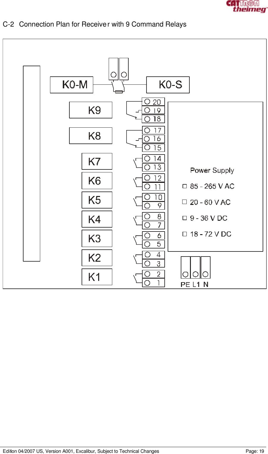
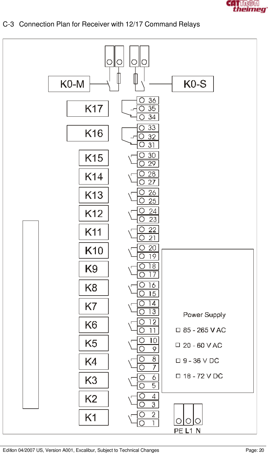
![Edition 04/2007 US, Version A001, Excalibur, Subject to Technical Changes Page: 7 2.2.3 Installing the Receiver To install the receiver, please use the mounting drawings contained in the appendix. 2.2.4 Electrical Connection of the Receiver For the electrical connection to the mains supply and the assignment of the contact terminals please refer to the connection plan in the appendix and the attached interface plan. The system can be put into operation after the completion of all installation work. 2.3 Transmitter 2.3.1 Inserting the Rechargeable Battery into the Transmitter: ⇒ Insert the charged battery [2] into the transmitter [3] (the transmitter should point downwards), ⇒ Lock the battery in place by turning the knob [1]. Warning! The radio rem ote control system is shipped with a discharged battery. The battery must be correctly charged before the system is put into operation. The transmitter is now ready for use. 2.3.2. Transmitter Labelling The transmitter can be given an individual labelling to suit the specific use of the radio remote control system. For this purpose, the system comes with a sheet of self-adhesive labels that can be affixed in the label fields on the transmitter. An optional second labelling sheet is available for specific applications.](https://usermanual.wiki/Cattron-North-America/EXC9158A/User-Guide-778674-Page-10.png)
![Edition 04/2007 US, Version A001, Excalibur, Subject to Technical Changes Page: 8 3. Putting into Operation 3.1 Transmitter 3.1.1 Transmitter Variants Excalibur transmitters come in two housing sizes equipped with 6, 8, 10 or 12 2-step pushbuttons 3.1.2 Switching On the Transmitter: Description 1 Status LEDs 2 Function pushbuttons 3 STOP pushbutton 4 ON pushbutton [1st step], Horn pushbutton [2nd step] 5 Battery compartment [on the rear side of the charger] 6 TransKey ⇒ The black Transkey [6], must be inserted Warning! Do not swap the transmitter/receiver TransKey! Perform the switch-on sequence as follows ⇒ Press the ON pushbutton [4] once – Status LED [1] lights red, ⇒ Press the STOP pushbutton [3] once [1st + 2nd step] – Status LED [1] lights orange, ⇒ Press the ON pushbutton [4] again once – Statu s LED [1] lights green, [The switch-on sequence must be completed within 10 seconds] The Transmitter can now be used to control the system. Note! The function of the pushbutton [2] is dependent on the program stored in the TransKey [6]. The transmitters have two-step pushbuttons. The 1st pressing point [1st step] is followed by a second pressing point (2nd step). See example pushbutton 4: ON [1st step], Horn [2nd step]](https://usermanual.wiki/Cattron-North-America/EXC9158A/User-Guide-778674-Page-11.png)
![Edition 04/2007 US, Version A001, Excalibur, Subject to Technical Changes Page: 9 3.1.3 Transmitter Blink Sequences [Status Indications] of the Status-LED Status Indications Status LED Action Normal operation Blinks green at 1.25 s intervals. — Early warning of low voltage Blinks red at 1.0 s intervals. Insert a charged battery within 10 min. or charge the battery. 3.1.4 Switching Off the Transmitter: ⇒ Press 1st step of STOP pushbutton [1] [OFF] or, ⇒ Press 2nd step of the STOP pushbutton [1] 3.1.5 TransKey The system -specific parameters are activated with the data stored in the TransKey. A label with the ID address is affixed to each TransKey. Warning! Transmitter and receiver TransKeys must not be swapped. The transmitter TransKey is black. The receiver TransKey is yellow. A swapping of the TransKeys results in a fault indication in the transmitter and in the receiver [see LED blink sequences]. The system will not go into operation.](https://usermanual.wiki/Cattron-North-America/EXC9158A/User-Guide-778674-Page-12.png)
![Edition 04/2007 US, Version A001, Excalibur, Subject to Technical Changes Page: 11 3.2.3 Relay Status Indication Each relay has an LED on the pcb for display of the relay status [only visible with removed housing cover]. 3.2.4 Power und Status Indication The receiver has 5 externally visible LEDs that display the current system status. LED Description 1: Power On Lights orange: as soon as the receiver has voltage 2: Without function 3: RF Reception Lights green: if valid data from the transmitter is received and both K0 relays are activated. Lights orange: if valid data from the transmitter is received and the K0 relays are deactivated. Lights red: if data from another transmitter [with invalid address] is received. OFF, if no transmitter is identified. 4: Command Lights green: if commands are received [normal condition] 5: Fault indication Blinks red: This LED flashes a fault code if the receiver detects a fault at any time. Note! A further LED [6], which displays the status of the second processor, is located on the processor pcb. The LED [6] blinks orange if the receiver does not detect a transmitter, and green if valid telegrams are received. If the 2nd processor detects a fault, it will signal this by blinking in red, see appendix for blink sequences.](https://usermanual.wiki/Cattron-North-America/EXC9158A/User-Guide-778674-Page-14.png)
![Edition 04/2007 US, Version A001, Excalibur, Subject to Technical Changes Page: 12 4. Charging the Transmitter Batteries with the Battery Charger 4.1 Functional Overview • Universally usable due to switching power supply technology [100-240 VAC] and primary-side exchangeable plug system, • Test phase at start of charging in order to ascertain the number of cells and to detect and indicate faulty batteries, • Short-circuit detection and electronic reversed polarity protection, • Monitoring of the charge condition during the entire charging time with a microcontroller, • Predischarging of the battery by button pressing possible; thereafter automatic switchover to charging, • Status display by LEDs, • Automatic switchover to pulse trickle charging. • Charging only in the temperature range +5 °C to +45 °C . 4.2 Indication on the Charger POWER UNIT UCC 11 0UCC 11 0N10467Q04574BT 097-00303C USOPENDischargeRea dyChargePowerPRESS[1][2][3] [4] [5]+-Positive insideEUUSAUK Indications Description Red ‘Power’ LED [1]: Permanent light signals that the charger is ready for operation. Lights up as soon as the charger is connected to the mains supply. Red ‘Charge’ LED [2]: Permanent light signals the charging after the contacting of the battery. Green ‘Ready’ LED [3]: Permanent light signals that the battery is charged. The green LED switches to blinking mode after approximately 2 minutes = pulse trickle charge. Yellow ‘Discharge’ LED [4]: Permanent light signals (after pressing of the yellow discharge button), the discharging. Simultaneously, the ‘Ready’ LED blinks for approximately 1 minute to signal the test phase. Discharge button [5]: Pressing the discharge button [for approx. 2 s] starts the discharging of the battery.](https://usermanual.wiki/Cattron-North-America/EXC9158A/User-Guide-778674-Page-15.png)
![Edition 04/2007 US, Version A001, Excalibur, Subject to Technical Changes Page: 13 After contacting the battery, the green ‘Ready [3]’ LED blinks for approx. 1 min simultaneously and signals the test phase. The battery is not contacting correctly if, after battery insertion, the ‘Charge [2]’ LED does not light and the ‘Ready [3]’ blinks simultaneously. Caution! Charge only Nickel / Cadmium [NiCd] or Nickel / Metal Hydride [NiMH] batteries - danger of explosion with other batteries! Warning! Do not open the charger. The charger may only be operated in dry indoor spaces. The charger must be protected against moisture and rain in order to exclude the danger of fire or an electric shock. Do not use the charger if the housing or mains plug is damaged; contact the customer service department of Cattron-Theimeg Europe GmbH & Co. KG. Keep the charger away from children. A failure to observe the safety instructions can result in damage to the charger, damage to the batteries or dangerous injuries to persons! 4.3 Charging The red ‘Charge [2]’ LED lights and signals the charging. The green ‘Ready [3]’ LED blinks simultaneously during the test phase but then goes off again after approx. 1 min. when the test phase is completed. Note! The battery should be discharged before the charging after approx. every 5 charging cycles. See section 4.5 Discharging. 4.4 Trickle Charging The charger automatically switches to pulse trickle charge after the completed charging. The red ‘Charge [2]’ LED goes off and the green ‘Ready [3]’ LED lights up permanently for approx. 2 min. After approx. 2 min., the indication changes to a green flashing light. The battery can then be either removed for use immediately or remain contacted in the charger. 4.5 Discharging The discharging is started by pressing the dis charge button [5] for approximately 2 s. The yellow ‘Discharge’ [4] LED lights and signals the discharging. The green ‘Ready’ [3] LED also blinks during the first minute but then goes off at the end of the test phase. After the completed discharge, which can in some cases take several hours, the charger automatically switches to the charge mode. 4.6 Defective Battery The inserted battery is defective and can no longer be charged if the green ‘Ready [3]’ LED blinks immediately after the contacting of the battery and the red ’Charge [2]’ LED also blinks sporadically after approximately 20 seconds. The battery must then be replaced.](https://usermanual.wiki/Cattron-North-America/EXC9158A/User-Guide-778674-Page-16.png)
![Edition 04/2007 US, Version A001, Excalibur, Subject to Technical Changes Page: 14 5. Maintenance The maintenance of the transmitter and the receiver is limited to a visual check. The charging of the transmitter battery is described in Section 4. 5.1 Cleaning the Transmitter The transmitter conforms to the protection class IP 65. This means that the transmitter can be cleaned with a moist cloth [if necessary, with a little washing-up liquid]. Then wipe dry. Warning! Do not immerse the transmitter in water!](https://usermanual.wiki/Cattron-North-America/EXC9158A/User-Guide-778674-Page-17.png)
![Edition 04/2007 US, Version A001, Excalibur, Subject to Technical Changes Page: 15 6. Appendix A-1 Technical Data of the Transmitter Transmitter Data Description Transmitter series: CT24 Excalibur. Frequency ranges: 402 – 470 MHz [Europe, China] 869 MHz [Europe] 915 MHz [USA] Transmission speed: 4.8 to 20 kBit/s. Power output: < 5 mW, respectively < 10 mW depending on version. Antenna: Internal. System addresses: 24 Bit = 16 million addresses. Power saving mode: Automatic switch-off [configurable: 0 - 30 minutes]. Voltage supply: Quick-swap rechargeable battery, NiMH, 3.6 V / 1600 mAh, operating time >12 hours at 100% ED. Control elements: 6, 8, 10, 12 pushbuttons [2-step]. Display: 5 Multi-LEDs for status and fault display, audible output. Weight: Approx. 290 g for 6 and 8 pushbutton variants, Approx. 350 g for 10 and 12 pushbutton variants. Dimensions: 180 x 64 x 39 mm [L x W x H] for 6 and 8 pushbutton variants, 235 x 64 x 39 mm [L x W x H] for 10 and 12 pushbutton variants. Housing: SB plastic, standard colours: silver/red with integrated drop protection. Operating temperature: -20 ºC to +60 ºC. IP protection class: IP 65 Safety category: EN 954-1 category 3 [Electronics and stop command]](https://usermanual.wiki/Cattron-North-America/EXC9158A/User-Guide-778674-Page-18.png)
![Edition 04/2007 US, Version A001, Excalibur, Subject to Technical Changes Page: 16 A-2 Technical Data of the Receiver Receiver Data Description Receiver series: CT24 Frequency ranges: 402 – 470 MHz, 869 MHz, 915 MHz Transmission speed: 4.8 to 20 kBit/s Receiver sensitivity: -107 dBm Antenna: Internal Typical response time: 70 ms System addresses: 24 Bit, > 16 million addresses Voltage supply: 85 – 265 V AC 50 - 60 Hz [Standard], 20 – 60 V AC [optional], 18 – 72 V DC [optional], 9 – 36 V DC [optional] Outputs 9 output relays, 17 output relays [optional with base], relays u p to 7A / 250 V AC Stop command: 2 monitored safety relays (additional to output relays) Connector: 2 cable glands, optional: Han16, Han24, Han32, Han64 Display: 5 Multi-LEDs for status and fault display Weight: Approx. 1050 g Dimensions: 150 x 170 x 105 mm [L x W x D], 235 x 170 x 105 mm [L x W x D] Case: Styrene butadiene, standard colours: matt silver-grey Operating temperature: -20 ºC to +60 ºC IP protection class: IP 65 Safety category: EN 954-1 category 3 Accessories: Mounting bracket A-3 Technical Data of the Charger Data of the Charger Description Microcontroller plug-type charger TH-ZB -PLG-UCC 110 Order number: BT 097-00303 Version: Processor-controlled charger Housing dimensions: Width: 60 mm Depth: 90 mm Height: 120 mm](https://usermanual.wiki/Cattron-North-America/EXC9158A/User-Guide-778674-Page-19.png)