Cattron North America MKU915A Remote Transmitter User Manual MKU System Manual
Laird Controls North America Inc. Remote Transmitter MKU System Manual
UserManual.wiki
>
Cattron North America
>
MKU915A User Manual
>
manual
Contents
1.
manual
2.
manual 2
manual
Navigation menu
Upload a User Manual
Namespaces
Wiki Guide
HTML
PDF
Info
Views
User Manual
Discussion / Help
Navigation


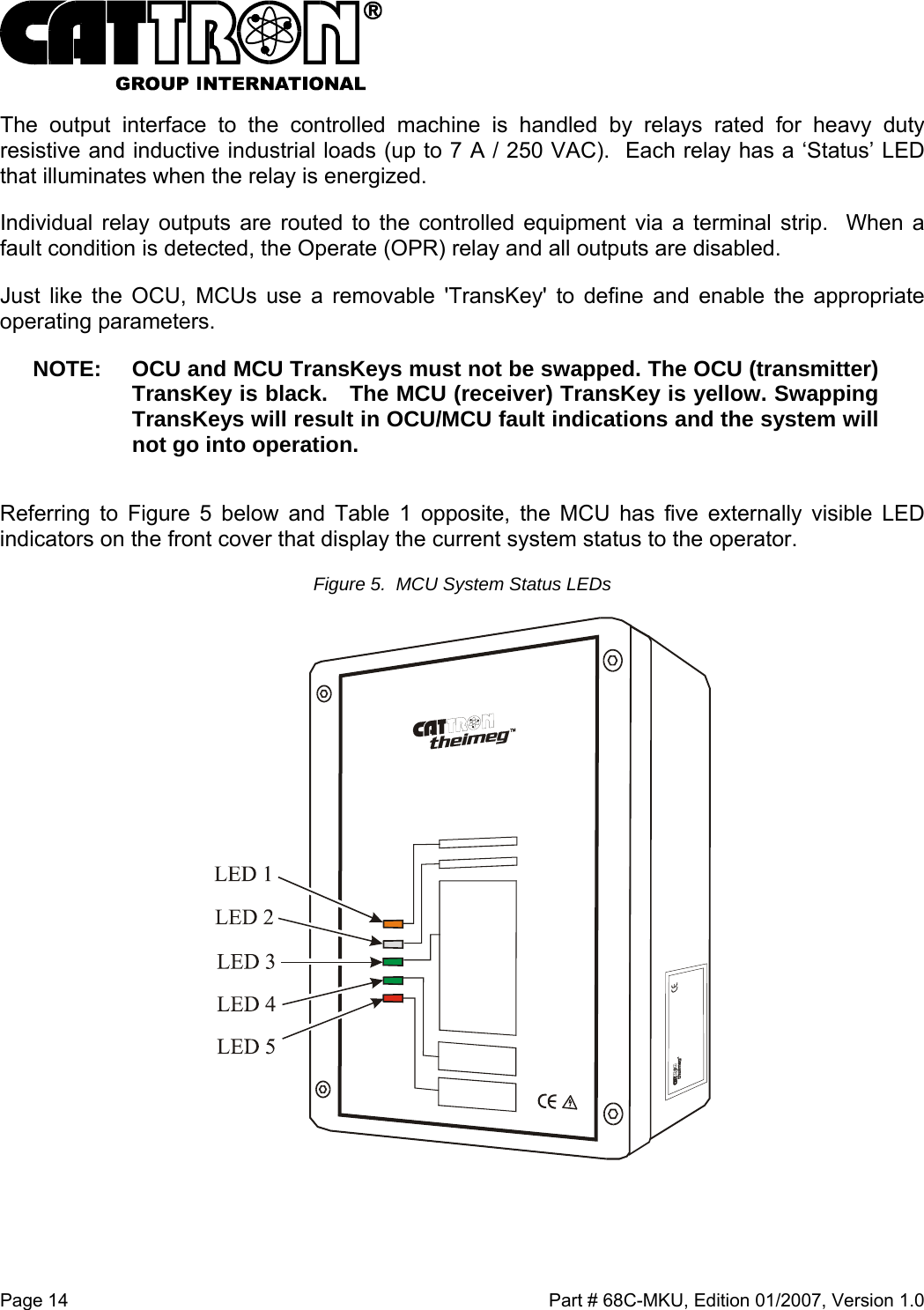
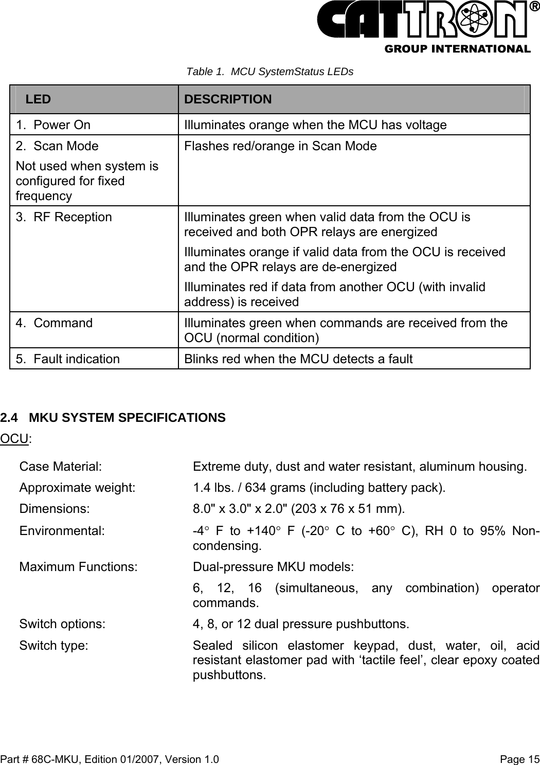
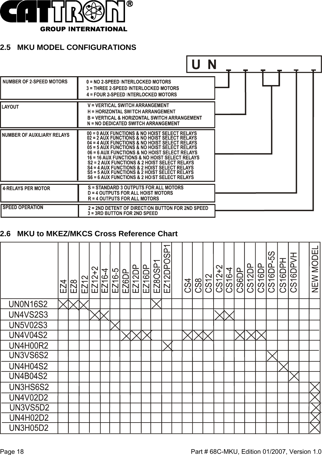
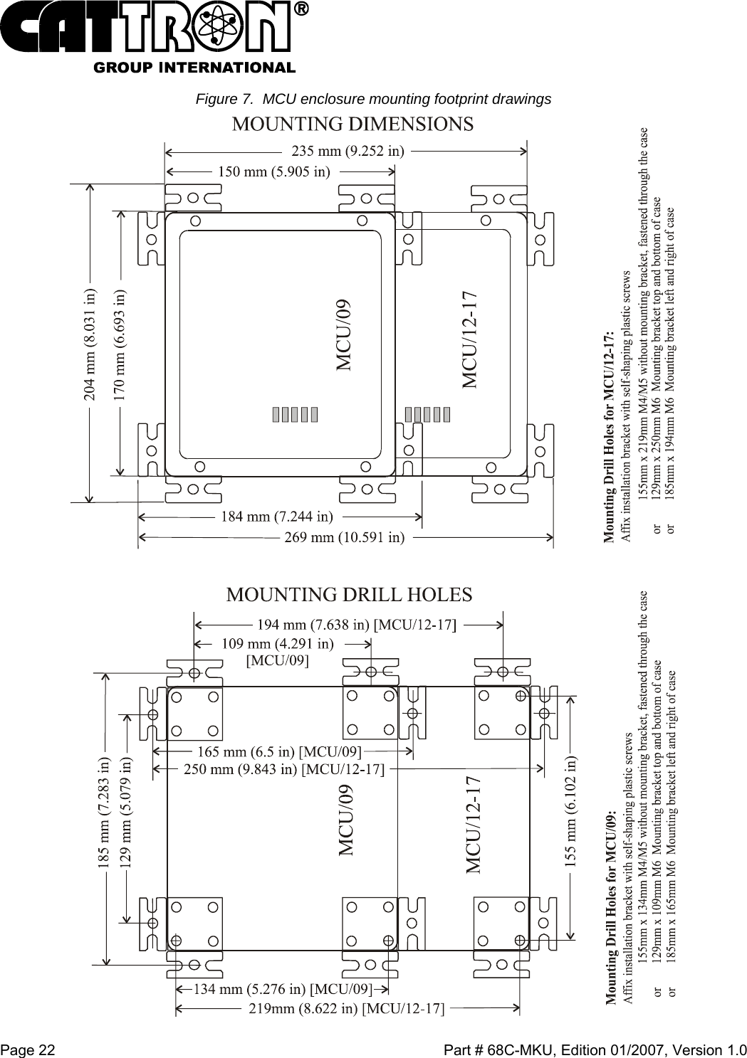
![Part # 68C-MKU, Edition 01/2007, Version 1.0 Page 17 MCU: Receiver series: CT24 Frequency range: 902 to 928 MHz Transmission speed: 4.8 to 20 kBit/s Receiver sensitivity: -107 dBm Antenna: Internal Typical response time: 70 ms System addresses: 24 Bit, > 16 million addresses Voltage supply: 85 – 265 V AC 50 - 60 Hz (Standard), 20 – 60 V AC (optional), 18 – 72 V DC (optional), 9 – 36 V DC (optional) Outputs 17 output relays up to 7 A / 250 VAC 9 output relays (optional), Stop command: 2 monitored safety relays (additional to output relays) Connector: 2 cable glands Display: 5 Multi-LEDs for status and fault display Weight: Approx. 2.4 lbs. / 1050 g Dimensions: 9-relay unit: 6.0" x 6.7" x 4.1" (150 x 170 x 105 mm) [L x W x D] 17-relay unit: 9.25" x 6.7" x 4.1" (235 x 170 x 105 mm) [L x W x D] Case Material: Styrene butadiene, standard colors: matt silver-grey Environmental: -4°F to +140° F (-20º C to +60° C), RH 0 to 95% non-condensing. IP protection class: IP 65](https://usermanual.wiki/Cattron-North-America/MKU915A.manual/User-Guide-768718-Page-19.png)